

Page 1
Troubleshooting Manual
www.hp.com/support/ljM402
www.hp.com/support/ljM403
www.hp.com/support/ljM426MFP
www.hp.com/support/ljM427MFP
For printer theory and troubleshooting
information, see the Repair Manual.
HEWLETT-PAC
KARD
2
1
M402d
M402n
M402dn
M402dw
M403n
M403d
M403dn
M403dw
2
1
M426dw
M426fdn
M426fdw
M427dw
M427fdn
M427fdw
LaserJet Pro MFP M426, M427
LaserJet Pro M402, M403
Page 2

Page 3

HP LaserJet Pro M402, M403 and
HP LaserJet Pro MFP M426, M427
Troubleshooting Manual
Page 4

Copyright and License
Trademark Credits
© Copyright 2015 HP Development Company,
L.P.
Reproduction, adaptation, or translation
without prior written permission is prohibited,
except as allowed under the copyright laws.
The information contained herein is subject to
change without notice.
The only warranties for HP products and
services are set forth in the express warranty
statements accompanying such products and
services. Nothing herein should be construed
as constituting an additional warranty. HP shall
not be liable for technical or editorial errors or
omissions contained herein.
Edition 1, 9/2015
Microsoft®, Windows®, Windows® XP, and
Windows Vista® are U.S. registered trademarks
of Microsoft Corporation.
Page 5

Conventions used in this guide
TIP: Helpful hints or shortcuts.
Reinstallation tip: Reinstallation helpful hints, shortcuts, or considerations.
NOTE: Information that explains a concept or how to complete a task.
IMPORTANT: Information that help the user to avoid potential printer error conditions.
CAUTION: Procedures that the user must follow to avoid losing data or damaging the printer.
WARNING! Procedures that the user must follow to avoid personal injury, catastrophic loss of data, or
extensive damage to the printer.
ENWW iii
Page 6

iv Conventions used in this guide ENWW
Page 7

For additional service and support information
HP service personnel, go to the Service Access Work Bench (SAW) at http://h41302.www4.hp.com/km/saw/
home.do.
Channel partners, go to HP Channel Services Network (CNS) at https://h30125.www3.hp.com/hpcsn.
At these locations, nd information on the following topics:
●
Install and congure
●
Printer specications
●
Up-to-date control panel message (CPMD) troubleshooting
●
Solutions for printer issues and emerging issues
●
Remove and replace part instructions and videos
●
Service advisories
●
Warranty and regulatory information
To access HP PartSurfer information from any mobile device, go to http://partsurfermobile.hp.com/ or scan
the Quick Response (QR) code below.
ENWW v
Page 8

vi For additional service and support information ENWW
Page 9

Table of contents
1 Theory of operation ....................................................................................................................................... 1
Related documentation and software ................................................................................................................... 2
Basic operation ...................................................................................................................................................... 3
Sequence of operation ........................................................................................................................ 4
Engine-control system .......................................................................................................................................... 5
DC controller ........................................................................................................................................ 6
Motor control ..................................................................................................................... 8
Fan control ........................................................................................................................ 8
Low-voltage power supply .................................................................................................................. 9
Over-current/over-voltage protection ........................................................................... 10
Safety ............................................................................................................ 10
Low-voltage power supply functions ........................................................... 10
High-voltage power supply ............................................................................................................... 11
High-voltage power supply circuits ................................................................................ 12
Fuser bias ........................................................................................................................ 12
Fuser control ..................................................................................................................................... 12
Fuser circuits ................................................................................................................... 13
Fuser control functions ................................................................................................... 14
Fuser heater protection .................................................................................................. 15
Engine laser/scanner system .............................................................................................................................. 16
Laser/scanner failure detection ........................................................................................................ 17
Safety ................................................................................................................................................ 17
Image-formation process ................................................................................................................. 18
Step 1: Primary charging ................................................................................................ 21
Step 2: Laser-beam exposure ......................................................................................... 22
Step 3: Development ...................................................................................................... 22
Step 4: Transfer ............................................................................................................... 23
Step 5: Separation ........................................................................................................... 24
Step 6: Fusing .................................................................................................................. 24
Step 7: Drum cleaning ..................................................................................................... 24
Toner cartridges ................................................................................................................................ 25
Design ............................................................................................................................. 25
ENWW vii
Page 10

Memory chip .................................................................................................................... 27
Toner level and cartridge life detection .......................................................................... 27
Pickup, feed, and delivery system ....................................................................................................................... 27
Sensors and switches ........................................................................................................................ 29
Motors, clutches, and solenoids ........................................................................................................ 31
Jam detection/prevention ................................................................................................................. 31
Paper feeder (optional Tray 3) ............................................................................................................................. 35
Basic operation .................................................................................................................................. 35
Paper path ....................................................................................................................... 35
Paper feeder controller ................................................................................................... 35
Motor control .................................................................................................................. 36
Pickup and feed operation ................................................................................................................ 36
Electrical components, pickup and feed ......................................................................... 36
Other functions ............................................................................................................... 37
Jam detection .................................................................................................................. 38
2 Solve problems ............................................................................................................................................ 39
For additional service and support ..................................................................................................................... 40
Solve problems checklist ..................................................................................................................................... 41
Solve problems checklist ................................................................................................................... 41
Print the menu map ........................................................................................................ 42
Print a conguration page .............................................................................................. 42
Print the service page (includes the event log) .............................................................. 43
Print the demo page ....................................................................................................... 43
Troubleshooting process ..................................................................................................................................... 44
Determine the problem source ......................................................................................................... 44
Pre-troubleshooting checklist ........................................................................................ 44
Determine the problem source ....................................................................................... 46
Power subsystem .............................................................................................................................. 47
Power-on checks ............................................................................................................. 47
Control panel checks ......................................................................................................................... 47
Tools for troubleshooting .................................................................................................................................... 49
Component diagnostics .................................................................................................................... 49
LED diagnostics ............................................................................................................... 49
Network LEDs (network models only) ......................................................... 49
Control panel LEDs ....................................................................................... 49
Engine diagnostics .......................................................................................................... 50
Engine test .................................................................................................... 50
Diagrams ........................................................................................................................................... 51
Diagrams: Block diagrams .............................................................................................. 51
Cross-sectional view of printer .................................................................... 51
viii ENWW
Page 11

Cross-sectional view of 550–sheet paper feeder ........................................ 52
Diagrams: Printed circuit assembly (PCA) connector locations ..................................... 53
Diagrams: DC controller connections ........................................................... 53
Paper feeder controller PCA ......................................................................... 54
Diagrams: External plug and port locations ................................................................... 54
Diagrams: Locations of major components ................................................................... 56
Major components (printer base) ................................................................. 56
Motor and fan ............................................................................................... 57
Rollers and pads (printer base) .................................................................... 58
PCAs (printer base) ....................................................................................... 59
Diagrams: Timing chart .................................................................................................. 60
Diagrams: Circuit diagrams ............................................................................................. 61
Advanced conguration with HP Embedded Web Server (EWS) and HP Device Toolbox
(Windows 7) ....................................................................................................................................... 62
Internal print-quality test pages ....................................................................................................... 64
Clean the paper path ....................................................................................................... 64
Clean the paper path (LCD control panel) .................................................... 64
Clean the paper path (touchscreen control panel) ...................................... 65
Print the conguration page ........................................................................................... 65
Print the conguration page from an LCD control panel ............................. 65
Print the conguration page from a touchscreen control panel ................. 65
Print-quality troubleshooting tools .................................................................................................. 66
Repetitive image defect ruler ......................................................................................... 66
Use a ruler to measure between repetitive defects ..................................... 66
Control panel menus ......................................................................................................................... 70
HP Web Services menu ................................................................................................... 70
Reports menu ................................................................................................................. 70
Quick Forms menu .......................................................................................................... 71
USB Flash Drive menu ..................................................................................................... 71
System Setup menu ........................................................................................................ 72
Service menu ................................................................................................................... 74
Network Setup menu ...................................................................................................... 77
Control panel message document (CPMD) ....................................................................................... 79
Control-panel message types ........................................................................................ 79
Control-panel messages and event log entries ............................................................. 79
30.XX Error Messages ................................................................................... 79
49.XX.YY Error Messages ............................................................................. 80
50.XX fuser errors ........................................................................................ 80
51.XX and 52 Laser/Scanner Errors ............................................................. 81
55.XXXX Error Messages .............................................................................. 82
57.XX Error Messages ................................................................................... 83
ENWW ix
Page 12

58.XX Error Messages ................................................................................... 83
59.XX Error Messages ................................................................................... 84
79 Errors ....................................................................................................... 85
Alpha Error Messages ................................................................................... 85
Event-log messages .......................................................................................................................... 96
Print the event log .......................................................................................................... 96
Print the event log (LCD control panel) ........................................................ 96
Print the event log (touchscreen control panel) .......................................... 97
Show an event log ........................................................................................................... 97
Event-log messages ....................................................................................................... 97
Clear paper jams ................................................................................................................................................ 101
Clear paper jams (M402, M403) ...................................................................................................... 101
Introduction .................................................................................................................. 101
Experiencing frequent or recurring paper jams? ......................................................... 101
Jam locations ................................................................................................................ 102
Clear paper jams in Tray 1 ............................................................................................ 103
Clear paper jams in Tray 2 ............................................................................................ 104
Clear paper jams in optional Tray 3 .............................................................................. 108
Clear paper jams in the fuser ........................................................................................ 111
Clear paper jams in the output bin ............................................................................... 115
Clear paper jams in the duplexer .................................................................................. 117
Clear paper jams (M426, M427) ...................................................................................................... 119
Introduction .................................................................................................................. 119
Experiencing frequent or recurring paper jams? ......................................................... 119
Jam locations ................................................................................................................ 120
Clear paper jams in the document feeder .................................................................... 122
Clear paper jams in Tray 1 ............................................................................................ 125
Clear paper jams in Tray 2 ............................................................................................ 126
Clear paper jams in optional Tray 3 .............................................................................. 130
Clear paper jams in the fuser ........................................................................................ 134
Clear paper jams in the output bin ............................................................................... 137
Clear paper jams in the duplexer .................................................................................. 140
Solve paper-handling problems ........................................................................................................................ 142
The printer picks up multiple sheets of paper ................................................................................ 142
The printer does not pick up paper ................................................................................................. 142
Solve image quality problems ........................................................................................................................... 143
Print quality examples .................................................................................................................... 143
Clean the printer ................................................................................................................................................ 150
Clean the pickup and separation rollers ......................................................................................... 150
Clean the paper path ....................................................................................................................... 150
Clean the paper path (LCD control panel) ..................................................................... 150
x ENWW
Page 13

Clean the paper path (touchscreen control panel) ....................................................... 150
Clean the touchscreen ..................................................................................................................... 150
Solve performance problems ............................................................................................................................ 152
Factors aecting print performance ............................................................................................... 152
Print speeds .................................................................................................................. 152
The product does not print or it prints slowly ................................................................................ 153
The product does not print ........................................................................................... 153
The product prints slowly ............................................................................................. 154
Solve connectivity problems ............................................................................................................................. 155
Solve direct-connect problems ....................................................................................................... 155
Solve network problems ................................................................................................................. 155
Poor physical connection .............................................................................................. 155
The computer is using the incorrect IP address for the product .................................. 155
The computer is unable to communicate with the product ......................................... 156
The product is using incorrect link and duplex settings for the network .................... 156
New software programs might be causing compatibility problems ........................... 156
The computer or workstation might be set up incorrectly .......................................... 156
The product is disabled, or other network settings are incorrect ............................... 156
Solve wireless network problems ................................................................................................... 157
Wireless connectivity checklist ..................................................................................... 157
The control panel displays the message: The wireless feature on this product has
been turned o ............................................................................................................. 157
The product does not print after the wireless conguration completes ..................... 158
The product does not print, and the computer has a third-party rewall installed ... 158
The wireless connection does not work after moving the wireless router or
product .......................................................................................................................... 158
Cannot connect more computers to the wireless product ........................................... 158
The wireless product loses communication when connected to a VPN ...................... 159
The network does not appear in the wireless networks list ........................................ 159
The wireless network is not functioning ...................................................................... 159
Service mode functions ..................................................................................................................................... 160
Service menu ................................................................................................................................... 160
Service menu settings .................................................................................................. 160
Restore the factory-set defaults .................................................................................. 160
Restore the factory-set defaults (LCD control panel) ................................ 160
Restore the factory-set defaults (touchscreen control panel) .................. 161
Secondary service menu ................................................................................................................. 161
Open the secondary service menu ............................................................................... 161
Open the secondary service menu (LCD control panel) ............................. 161
Open the secondary service menu (touchscreen control panel) ............... 161
Secondary service menu structure ............................................................................... 162
ENWW xi
Page 14

Developer's menu ............................................................................................................................ 162
Open the Developer's menu (LCD control panel) ......................................................... 162
Open the Developer's menu (touchscreen control panel) ........................................... 163
Product resets ................................................................................................................................. 164
NVRAM initialization ..................................................................................................... 164
Solve fax problems (fax models only) ............................................................................................................... 165
Introduction ..................................................................................................................................... 165
Fax troubleshooting checklist ......................................................................................................... 165
Solve general fax problems ............................................................................................................ 166
Faxes are sending slowly .............................................................................................. 166
Fax quality is poor ......................................................................................................... 167
Fax cuts o or prints on two pages .............................................................................. 168
Solve email problems (M426, M427 printes) .................................................................................................... 169
Cannot connect to the email server ................................................................................................ 169
Validate the SMTP gateway (Windows) .......................................................................................... 169
Validate the LDAP gateway (Windows) ........................................................................................... 169
Manually update the rmware .......................................................................................................................... 170
Manually update the rmware (LCD control panel) ........................................................................ 170
Manually update the rmware (touchscreen control panel) .......................................................... 170
Appendix A Printer specications .................................................................................................................. 171
Printer dimensions M426 and M427 ................................................................................................................. 172
Printer dimensions M402 and M403 ................................................................................................................. 174
Printer space requirements ............................................................................................................................... 176
Power consumption, electrical specications, and acoustic emissions ........................................................... 176
Operating-environment range .......................................................................................................................... 176
Certicate of Volatility ....................................................................................................................................... 177
Index ........................................................................................................................................................... 181
xii ENWW
Page 15

List of tables
Table 1-1 Sequence of operation .......................................................................................................................................... 4
Table 1-2 Motors ................................................................................................................................................................... 8
Table 1-3 Fans ....................................................................................................................................................................... 8
Table 1-4 List of DC voltages ................................................................................................................................................ 9
Table 1-5 Low-voltage power supply functions ................................................................................................................. 10
Table 1-6 High-voltage power supply circuits .................................................................................................................... 12
Table 1-7 Fuser components .............................................................................................................................................. 13
Table 1-8 Fuser control functions ...................................................................................................................................... 14
Table 1-9 Sensors ............................................................................................................................................................... 20
Table 1-10 Image formation process ................................................................................................................................. 21
Table 1-11 Toner cartridge functions ................................................................................................................................. 26
Table 1-12 Pickup, feed, and delivery system functions ................................................................................................... 28
Table 1-13 Photo sensors and switches ............................................................................................................................. 30
Table 1-14 Motors, solenoids, and clutches ....................................................................................................................... 31
Table 1-15 Jams that the printer detects ........................................................................................................................... 32
Table 1-16 Electrical component list, paper feeder ........................................................................................................... 36
Table 1-17 Motors, paper feeder ........................................................................................................................................ 36
Table 1-18 Electrical components, pickup and feed .......................................................................................................... 37
Table 1-19 Other functions, paper feeder .......................................................................................................................... 37
Table 2-1 DC controller connectors .................................................................................................................................... 53
Table 2-2 Paper feeder controller PCA connectors ............................................................................................................ 54
Table 2-3 M402, M403 external plugs and ports ............................................................................................................... 54
Table 2-4 M426, M427 external plugs and ports ............................................................................................................... 55
Table 2-5 Major components (printer base) ....................................................................................................................... 56
Table 2-6 Motor and fan (printer base) .............................................................................................................................. 57
Table 2-7 Rollers and pads (printer base) .......................................................................................................................... 58
Table 2-8 Main PCAs (printer base) ..................................................................................................................................... 59
Table 2-9 Repetitive defects ............................................................................................................................................... 66
Table 2-10 Event-log messages (X=0: black cartridge) ..................................................................................................... 97
Table 2-11 Fax event log codes ........................................................................................................................................ 100
Table 2-12 Print quality examples ................................................................................................................................... 143
Table 2-13 Secondary Service menu ................................................................................................................................ 162
ENWW xiii
Page 16

Table A-1 Operating-environment specications ............................................................................................................ 176
xiv ENWW
Page 17

List of gures
Figure 1-1 Relationship between the main printer systems ............................................................................................... 3
Figure 1-2 Engine-control system ........................................................................................................................................ 5
Figure 1-3 DC controller block diagram ................................................................................................................................ 6
Figure 1-4 Low-voltage power-supply circuit ...................................................................................................................... 9
Figure 1-5 High-voltage power supply circuits .................................................................................................................. 12
Figure 1-6 Fuser components ............................................................................................................................................ 13
Figure 1-7 Fuser control ..................................................................................................................................................... 14
Figure 1-8 Laser/scanner system ....................................................................................................................................... 16
Figure 1-9 Image-formation system .................................................................................................................................. 18
Figure 1-10 Fuser motor (M1) and image formation components .................................................................................... 19
Figure 1-11 Toner-level sensor .......................................................................................................................................... 20
Figure 1-12 Image-formation process ............................................................................................................................... 20
Figure 1-13 Primary charging ............................................................................................................................................. 21
Figure 1-14 Laser-beam exposure ..................................................................................................................................... 22
Figure 1-15 Development ................................................................................................................................................... 22
Figure 1-16 Primary transfer .............................................................................................................................................. 23
Figure 1-17 Separation ....................................................................................................................................................... 24
Figure 1-18 Fusing .............................................................................................................................................................. 24
Figure 1-19 Drum cleaning ................................................................................................................................................. 25
Figure 1-20 Toner cartridge system ................................................................................................................................... 26
Figure 1-21 Pickup, feed, and delivery system .................................................................................................................. 28
Figure 1-22 Sensors and switches for the pickup, feed, and delivery system .................................................................. 29
Figure 1-23 Motors, solenoids, and clutches ..................................................................................................................... 31
Figure 1-24 Jam detection sensors .................................................................................................................................... 32
Figure 1-25 Optional Tray 3 paper path ............................................................................................................................. 35
Figure 1-26 Paper feeder controller ................................................................................................................................... 36
Figure 1-27 Electrical components, pickup and feed ......................................................................................................... 37
Figure 2-1 Cross-sectional view of printer ......................................................................................................................... 51
Figure 2-2 Cross-sectional view of 500–sheet paper feeder ............................................................................................ 52
Figure 2-3 DC controller PCA connectors ........................................................................................................................... 53
Figure 2-4 Paper feeder controller PCA connectors ........................................................................................................... 54
Figure 2-5 M402, M403 external plugs and ports locations .............................................................................................. 54
ENWW xv
Page 18

Figure 2-6 M426, M427 external plug and port locations ................................................................................................. 55
Figure 2-7 Major components (printer base) ..................................................................................................................... 56
Figure 2-8 Motor and fan .................................................................................................................................................... 57
Figure 2-9 Rollers and pads (printer base) ......................................................................................................................... 58
Figure 2-10 Main PCAs (printer base) ................................................................................................................................. 59
Figure 2-11 General timing chart ....................................................................................................................................... 60
Figure 2-12 General circuit diagram (printer base) ............................................................................................................ 61
Figure 2-13 Examples of repetitive defects ....................................................................................................................... 67
Figure 2-14 Place the ruler on the page ............................................................................................................................. 68
Figure 2-15 Locate the next repetitive defect ................................................................................................................... 68
Figure 2-16 Determine the defective assembly ................................................................................................................. 69
Figure A-1 Dimensions for the M426 and M427 models ................................................................................................. 172
Figure A-2 Dimensions for the optional 550-sheet tray .................................................................................................. 172
Figure A-3 Dimensions for the printer with the optional 550-sheet tray ....................................................................... 173
Figure A-4 Dimensions for the M402 and M403 models ................................................................................................. 174
Figure A-5 Dimensions for the optional 550-sheet tray .................................................................................................. 174
Figure A-6 Dimensions for the printer with the optional 550-sheet tray ....................................................................... 175
Figure A-7 Certicate of Volatility M402/M403 (1 of 2) ................................................................................................... 177
Figure A-8 Certicate of Volatility M402/M403 (2 of 2) ................................................................................................... 178
Figure A-9 Certicate of Volatility M426/M427 (1 of 2) ................................................................................................... 179
Figure A-10 Certicate of Volatility M426/M427 (2 of 2) ................................................................................................ 180
xvi ENWW
Page 19

1 Theory of operation
●
Related documentation and software
●
Basic operation
●
Engine-control system
●
Engine laser/scanner system
●
Pickup, feed, and delivery system
●
Paper feeder (optional Tray 3)
ENWW 1
Page 20

Related documentation and software
HP service personnel, go to the Service Access Work Bench (SAW) at http://h41302.www4.hp.com/km/saw/
home.do.
Channel partners, go to HP Channel Services Network (CSN) at https://h30125.www3.hp.com/hpcsn.
2 Chapter 1 Theory of operation ENWW
Page 21

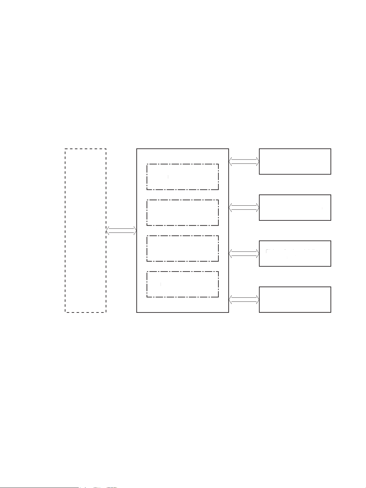
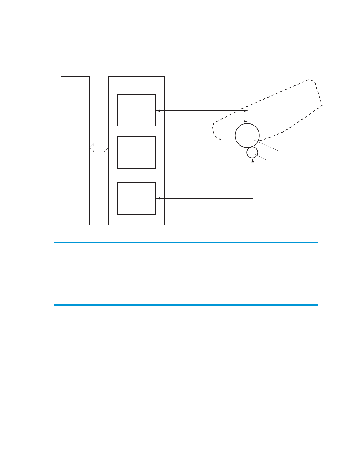
Basic operation
Engine-control system
Laser scanner system
Image-formation system
Pickup, feed, and delivery system
Accessory
Engine-control system
Laser scanner system
Image-formation system
Pickup, feed, and delivery system
Accessor
y
The printer routes all high-level processes through the formatter, which stores font information, processes
the print image, and communicates with the host computer.
The basic printer operation comprises the following systems:
●
Engine-control system
●
Laser/scanner system
●
Image-formation system
●
Pickup, feed, and delivery system
●
Accessory (optional paper feeder)
Figure 1-1 Relationship between the main printer systems
ENWW Basic operation 3
Page 22

Sequence of operation
The DC controller PCA controls the operating sequence, as described in the following table.
Table 1-1 Sequence of operation
Period Duration Description
Waiting From the time the power is turned on, the door is
closed, or when the printer exits Sleep mode until the
printer is ready for printing.
Standby From the end of the waiting sequence or the last
rotation until the formatter receives a print command,
or until the printer is turned o.
Initial rotation From the time the formatter receives a print command
until the paper enters the paper path.
Printing From the time the rst sheet of paper enters the paper
path until the last sheet passes through the fuser.
●
Heats the fuser lm in the fuser
●
Detects the toner cartridge
●
Rotates and stops each motor
●
Rotates and stops each fan
●
Cleans the transfer roller
●
Is in the Ready state
●
Enters Sleep mode if the formatter sends the
sleep command
●
Rotates and stops each fan
●
Rotates each motor
●
Rotates each fan
●
Activates the high-voltage power supply (highvoltage bias)
●
Prepares the laser/scanner unit
●
Warms the fuser to the correct temperature
●
Forms the image on the photosensitive drums
●
Transfers the toner to the paper
Last rotation From the time the last sheet of paper exits the fuser
until the motors stop rotating.
●
Fuses the toner image onto the paper
●
Stops each motor
●
Stops each fan
●
Stops the high-voltage power supply (highvoltage bias)
●
Stops the laser/scanner unit
●
Turns the fuser heater o
●
If another print command is received, the printer
enters the initial rotation period when the last
rotation is complete.
4 Chapter 1 Theory of operation ENWW
Page 23
Engine-control system
Formatter
Engine-control system
DC controller
Low-voltage power supply
Laser scanner system
Image-formation system
Pickup, feed, and delivery
system
Accessory
High-voltage power supplies
Fuser power supply
Formatter
Engine-control system
DC controller
Low-voltage power suppl
y
Laser scanner system
Image-formation system
Pickup, feed, and delivery
sy
stem
Accessor
y
igh-voltage power supplies
Fuser power suppl
y
The engine-control system receives commands from the formatter and interacts with the other main systems
to coordinate all printer functions. The engine-control system consists of the following components:
●
DC controller
●
Low-voltage power supply
●
High-voltage power supplies
●
Fuser power supply
Figure 1-2 Engine-control system
ENWW Engine-control system 5
Page 24
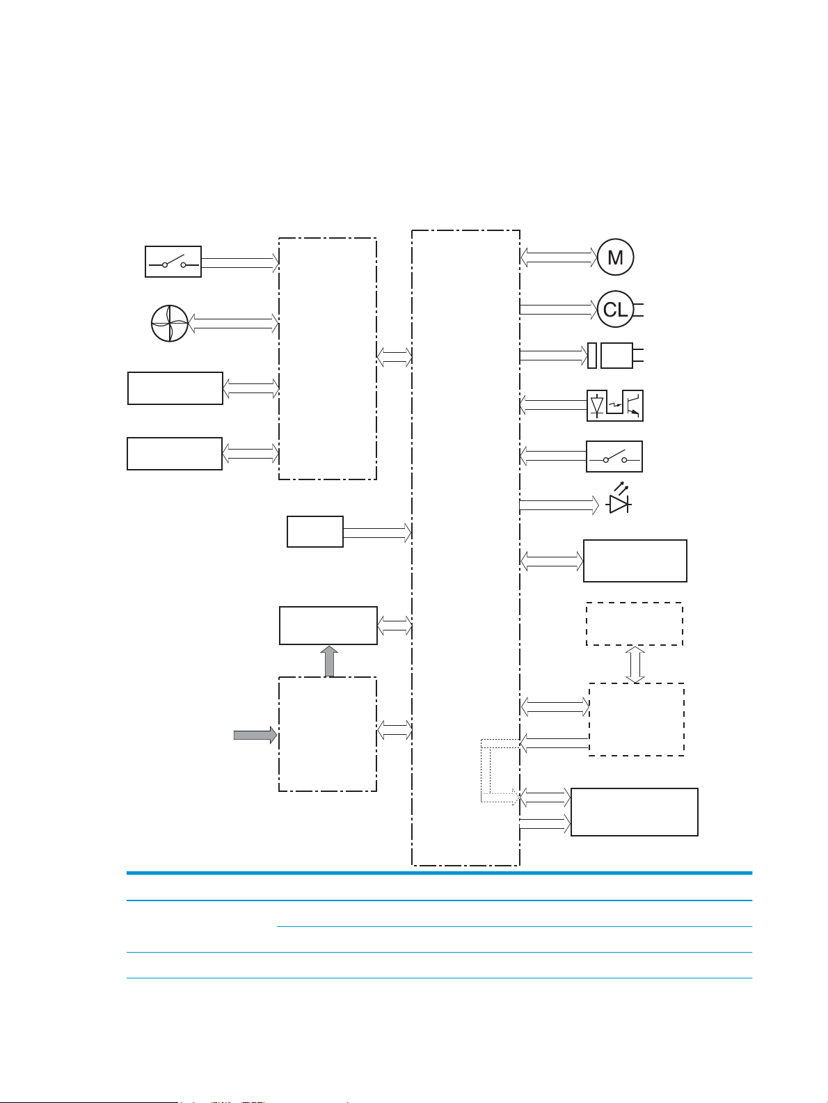
DC controller
Transfer roller
High-voltage
power supply
Fan
Cartridge
LED
Motor
Clutch
Solenoid
Switch
Photointerrupter
Formatter
Control panel
Accessory
Laser scanner ass’y
Fuser
AC input
Low-voltage
power supply
DC controller
Switch
Sensor
The DC controller controls the operation of the printer and its components. The DC controller starts the
printer operation when the printer power is turned on and the power supply sends DC voltage to the DC
controller. After the printer enters the standby period, the DC controller sends out various signals to operate
motors, solenoids, and other printer components based on the print command and image data that the host
computer sends.
Figure 1-3 DC controller block diagram
Component type Abbreviation Description
Motor M1 Fuse motor
M3 Scanner motor
Fan Fm1 Main fan
6 Chapter 1 Theory of operation ENWW
Page 25

Component type Abbreviation Description
Solenoid SL1 Cassette pickup solenoid
SL2 MP tray pickup solenoid
SL3 Duplex switchback solenoid
Clutch CL1 Duplex re-pickup clutch
Switch SW1 Power switch
SW101 Cartridge door switch
Photointerrupter PS1a Media width sensor
PS2b Duplex feed sensor
PS1 Cassette media out sensor
PS2 Top sensor
PS3 MP tray media out sensor
PS4 Output bin media-full sensor
PS13 Fuser output sensor
Sensor TH1 Environment sensor
LED LED1 Power supply LED
1
Duplex models only.
ENWW Engine-control system 7
Page 26

Motor control
The printer has two motors. The motors drive the components in the paper-feed and image-formation
systems.
The DC controller monitors the fuser motor and the scanner motor to determine if a motor has failed. It
noties the formatter when it encounters the following conditions:
●
●
Table 1-2 Motors
Abbreviation Name Purpose Failure detection
Startup failure: the motor does not reach a specied speed within a specied time from when the motor
starts.
Rotational failure: the rotational speed of the motor is not in the specied range for a specied time
after the motor reaches a specied speed.
Fan control
The printer has one fan for preventing the temperature from rising in the printer and for cooling the printed
pages.
The DC controller determines if there is a fan failure and noties the formatter if the fan locks for a specied
time from when the fan starts.
Table
M1 Fuser motor Drives the pressure roller and delivery roller;
the pressurization and release of the pressure
roller; and the engagement and
disengagement of the primary and secondary
transfer rollers
M3 Scanner motor Drives the scanner mirror Yes
1-3 Fans
Abbreviation Name Cooling area Type Speed
FM1 Main fan Inside of printer Intake Full
Yes
8 Chapter 1 Theory of operation ENWW
Page 27
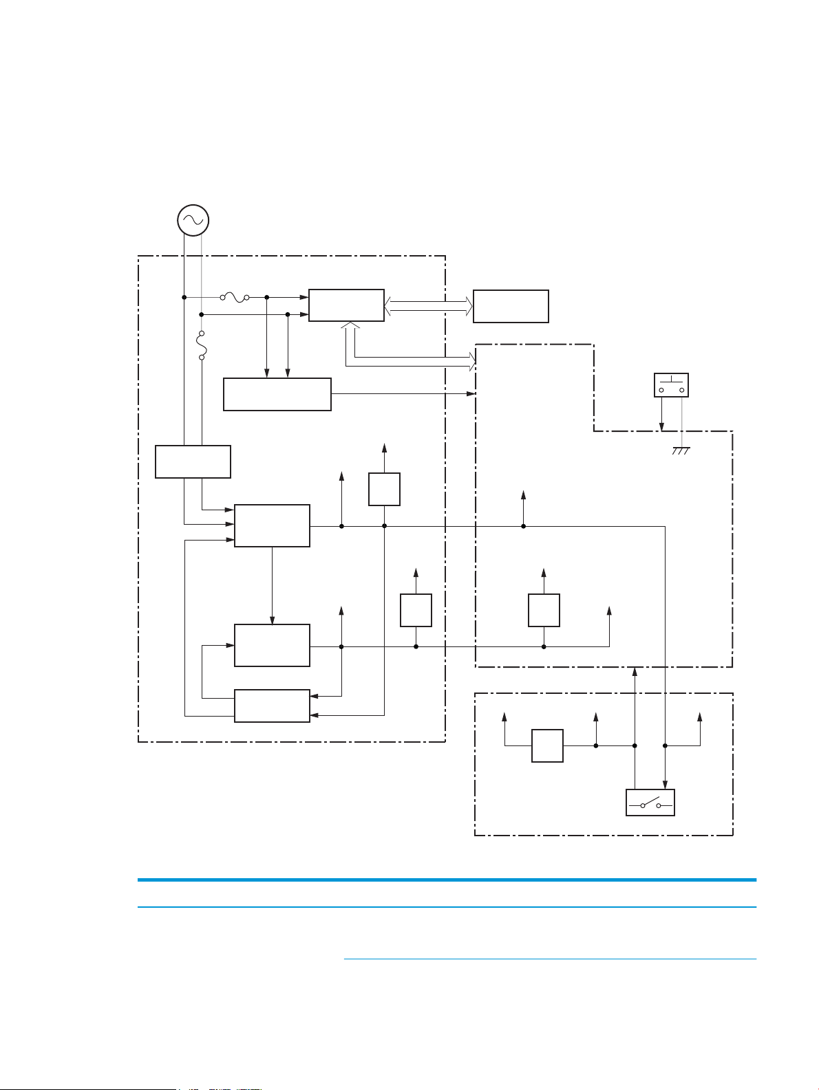
Low-voltage power supply
AC input
+24VA
FET
FET
+24VB
+24VC
+24VD
+24VBSNS
+24VA
FET
PWRSW
+3.3VA
FET
+3.3VC
+3.3VB
+3.3VA
+24VA
Low-voltage power supply
Rectifying
circuit
Protection
circuit
+24V
generation
circuit
Fuse
FU101
Fuse
FU102
+3.3V
generation
circuit
Fuser
Power switch
SW1
DC controller
High-voltage power supply
Interlock switch
SW101
Fuser control
circuit
FREQSNS_LVT
Frequency
detection circuit
The low-voltage power-supply (LVPS) circuit converts the AC power from the wall receptacle into the DC
voltage that the printer components use.
Figure 1-4 Low-voltage power-supply circuit
Table 1-4 List of DC voltages
DC power supply Description
+24V +24VA Constantly supplied
Becomes 4.5V during active OFF or inactive OFF
ENWW Engine-control system 9
Page 28

Table 1-4 List of DC voltages (continued)
DC power supply Description
+3.3V +3.3VA Constantly supplied
Over-current/over-voltage protection
The low-voltage power supply has a protective function against overcurrent and overvoltage conditions to
prevent failures in the power supply circuit. If an overcurrent or overvoltage event occurs, the system
automatically cuts o the output voltage.
+24VB Stopped when cartridge door is opened. (SW101)
Stopped during active OFF or inactive OFF
+24VC Stopped when cartridge door is opened. (SW101)
Stopped during active OFF or inactive OFF
+24VD Constantly supplied
Stopped during active OFF or inactive OFF
+3.3VB Constantly supplied
Stopped during active OFF or inactive OFF
+3.3VC Constantly supplied
Stopped during inactive OFF
If the DC power is not being supplied from the low-voltage power supply, the protective function might have
activated. In this case, turn o the power switch, and then unplug the power cord. Do not plug in the power
cord or turn the power switch on again until the root cause is found.
In addition, two fuses in the low-voltage power supply protect against an overcurrent event. If an overcurrent
event occurs in the AC line, the fuse blows and cuts o the power distribution.
Safety
For personal safety, the printer interrupts +24VB and +24VC power when the cartridge door detection switch
is turned o. This stops DC power supply to the high-voltage power supply (HVPS).
The remote switch control circuit turns on or o the printer power so that the AC power ows even the power
switch is turned o. Unplug the printer power cord before disassembling the printer.
Low-voltage power supply functions
The printer has the following low-voltage power supply functions.
1-5 Low-voltage power supply functions
Table
Failure detective function Applied
Sleep mode NA
Power supply voltage detection NA
Automatic power OFF NA
Automatic power ON/OFF NA
10 Chapter 1 Theory of operation ENWW
Page 29

Table 1-5 Low-voltage power supply functions (continued)
Failure detective function Applied
Active OFF Yes
Inactive OFF Yes
Network mode NA
Power switch illumination Yes
Low-voltage power supply failure detection Yes
Power save mode NA
High-voltage power supply
The DC controller controls the high-voltage power supply (HVPS) to generate biases. The high-voltage power
supply delivers the high-voltage biases to the following components used to transfer toner during the imageformation process:
●
Primary charging roller (in the toner cartridge)
●
Developing roller (in the toner cartridge)
●
Transfer roller
●
Pressure roller
ENWW Engine-control system 11
Page 30
High-voltage power supply circuits
PRI
DEV
TR
DC controller
High-voltage power supply
To primary charge roller
To developing roller
Cartridge
Photosensitive drum
Transfer roller
Primary
charging bias
circuit
Developing
bias circuit
Transfer bias
circuit
The high-voltage power supply contains the following separate circuits.
Figure 1-5 High-voltage power supply circuits
Fuser bias
Fuser control
Table 1-6 High-voltage power supply circuits
Circuit Description
Primary-charging-bias generation The primary charging bias negatively charges the surface of the photosensitive drum to
prepare for image formation.
Developing-bias generation The developing bias adheres toner to an electrostatic latent image formed on the
photosensitive drums.
Transfer-bias generation The primary transfer bias transfers the toner from each photosensitive drum onto the
page.
The printer uses on-demand fusing. The fuser bias is DC positive for improved print quality. The fuser bias
circuit is located in the high-voltage power supply, HVPS (T).
The DC controller and components in the fuser perform the following functions related to fuser operation:
●
Control fuser temperature
●
Detect fuser failures
●
Prevent excessive temperature rise
12 Chapter 1 Theory of operation ENWW
Page 31

●
FUSER TEMPERATURE signal
FUSER HEATER CONTROL signal
DC controller
Low-voltage power supply
Fuser control circuit
TH1
TP1
H1
Pressure roller
Fuser film
Fuser heater
control circuit
Fuser heater
safety circuit
●
Fuser circuits
The fuser heater control circuit and the fuser heater safety circuit control the fuser temperature according to
commands from the DC controller. The fuser consists of the following major components:
Figure 1-6 Fuser components
Detect remaining life in the fuser
Determine if the correct fuser is installed
ENWW Engine-control system 13
Table 1-7 Fuser components
Type of component Abbreviation Name Function
Heaters H1 Fuser main heater Heats the center of the fuser lm
Thermistors
(Contact type)
Thermoswitch
(Contact type)
TH1 Main thermistor Detects the center temperature of
TP1 Thermoswitch Prevents an abnormal temperature
assembly
the fuser heater
rise in the fuser heater
Page 32

Fuser control functions
Fuser heater
safety circuit
FREQSNS
TP1
Fuser heater (H1)
Fuser film ass’y
TP1: Thermal switch
TH1: Thermistor
Fuser
Pressure roller
FSRD
RLYD
FSRTH
+24V
Low-voltage suppry supply
Fuser control
RL101
DC controlle
r
Fuser heater
control circuit
Relay control
circuit
Current detection
circuit
TH1
Figure 1-7 Fuser control
The printer has the following fuser control functions.
1-8 Fuser control functions
Table
Failure detection function Supported feature
Fuser temperature control Yes
14 Chapter 1 Theory of operation ENWW
Page 33

Table 1-8 Fuser control functions (continued)
Failure detection function Supported feature
Fuser failure detection Yes
Frequency detection circuit failure detection Yes
Fuser pressure release mechanism failure detection No
Fuser type discrepancy detection No
Fuser type identication detection Yes
Fuser presence detection No
Fuser life detection No
Relay failure detection No
Pressure roller cleaning Yes
Fuser heater protection
Fuser heater protection is a feature that detects excessive temperatures in the fuser and interrupts the power
supply to the fuser heater.
The following three protective components prevent the fuser heater from excessive rising temperature:
●
DC controller: When a thermistor or sub-thermistor detects a temperature above a certain threshold,
the DC controller interrupts power to the specic heater.
●
Fuser-heater safety circuit: The fuser heater safety circuit monitors the detected temperature of the
sub thermistors.
●
Thermoswitch: If the temperature in the heaters is abnormally high, and the temperature in the
thermoswitch exceeds a specied value, the contact to the thermoswitch breaks.
ENWW Engine-control system 15
Page 34

Engine laser/scanner system
Laser ass’y
BD sensor
Scanner mirror
Scanner motor ass’y
Photosensitive drum
DC controller
The laser/scanner system forms the latent electrostatic image on the photosensitive drums inside each of the
toner cartridges.
The DC controller receives instructions from the formatter regarding the image of the page to be printed. The
DC controller signals the lasers to emit light, and the laser beams pass through lenses and onto the scanner
mirror, which rotates at a constant speed. The mirror reects the beam onto the photosensitive drum in the
pattern required for the image, exposing the surface of the drum so it can receive toner.
The main components of the laser/scanner system, which are controlled by signals sent from the DC
controller, are:
●
Laser assembly
●
Scanner motor assembly
●
Beam detect (BD) sensor
●
Scanner mirror
Figure 1-8 Laser/scanner system
16 Chapter 1 Theory of operation ENWW
Page 35

Laser/scanner failure detection
The DC controller determines an optical unit failure and noties the formatter of the error status for the
following supported conditions:
Failure detection function Supported feature
Safety
Beam detect (BD) failure detection: A specied BD interval is not detected within a
specied period during the scanner motor drive.
Laser/scanner motor startup failure: The scanner motor does not reach a specied
rotation frequency within a specied period of time from when the laser/scanner starts up.
Laser/scanner motor abnormal rotation: The laser/scanner motor does not reach a
specied rotational frequency within a specied period of time during a print operation.
Laser scanner failure detection A specied laser intensity is not detected. No
Yes
Yes
Yes
The laser/scanner assembly has a mechanical laser shutter. For the safety of users and service technicians,
the laser shutter interrupts the optical path of the laser/scanner assembly when the top door is opened
(SW101).
ENWW Engine laser/scanner system 17
Page 36

Image-formation process
The image-formation system creates the printed image on the paper. The system consists of the following
components:
●
Toner cartridge
●
Transfer roller
●
Fuser
●
Laser/scanner
●
High-voltage power supply
The DC Controller controls the internal components of the image formation system (according to commands
received from the formatter) to form the toner image on the photosensitive drum surface. The toner image is
then transferred to the print media and fused.
Figure 1-9 Image-formation system
The fuser motor (M1) drives the following image formation components:
●
Photosensitive drum
●
Developing roller
●
Primary charging roller (follows the photosensitive drum)
●
Transfer roller (follows the photosensitive drum)
●
Pressure roller
●
Fuser lm (follows the pressure roller)
NOTE: The primary charging roller and developer roller are located in the toner cartridge.
18 Chapter 1 Theory of operation ENWW
Page 37

Figure 1-10 Fuser motor (M1) and image formation components
DC controller
M1
Abbreviation Component
M1 Fuser motor
The following gure shows the toner-level sensor for the image-formation system.
ENWW Engine laser/scanner system 19
Page 38

Figure 1-11 Toner-level sensor
DC controller
Toner level
sensor
: Paper path
: Direction of drum rotation
: Functional block
: Step
Pickup
Delivery
Fusing
Transfer
Drum cleaning
Developing
Latent image formation
6. Fusing
5. Separation
7. Drum cleaning
1. Primary charging
2. Laser beam exposure
4. Transfer
3. Developing
Table 1-9 Sensors
Abbreviation Component Replacement part number
The image-formation process consists of ten steps divided into ve functional blocks.
Figure 1-12 Image-formation process
Toner-level sensor
20 Chapter 1 Theory of operation ENWW
Page 39

Table 1-10 Image formation process
Photosensitive drum
Primary charging roller
Primary charging bias
Functional block Steps Description
Latent image formation 1. Primary charging
Development 3. Development Toner adheres to the electrostatic latent image on the
Transfer 4. Transfer
Fusing 6. Fusing The toner fuses to the paper to make a permanent
Drum cleaning 7. Drum cleaning Residual toner is removed from the drum.
Step 1: Primary charging
To prepare for latent image formation, the surface of the photosensitive drum is charged with a uniform
negative charge. The primary charging roller receives the primary charging bias, and then the roller charges
the drum directly.
Figure 1-13 Primary charging
An invisible latent image forms on the surface of the
photosensitive drums.
2. Laser-beam exposure
photosensitive drum.
The toner image transfers to the paper.
5. Separation
image.
ENWW Engine laser/scanner system 21
Page 40

Step 2: Laser-beam exposure
Photosensitive drum
Laser beam
Developer roller
Developing bias
Photosensitive drum
Developer blade
The laser beam scans the photosensitive drum to neutralize the negative charge on portions of the drum
surface. An electrostatic latent image forms where the negative charge was neutralized.
Figure 1-14 Laser-beam exposure
Step 3: Development
Toner acquires a negative charge as a result of the friction from the developing roller rotating against the
developing blade. When the negatively charged toner comes in contact with the drum, it adheres to the
electrostatic latent image. When the toner is on the drum, the image becomes visible. The developing bias is
applied to the developing roller.
Figure 1-15 Development
22 Chapter 1 Theory of operation ENWW
Page 41
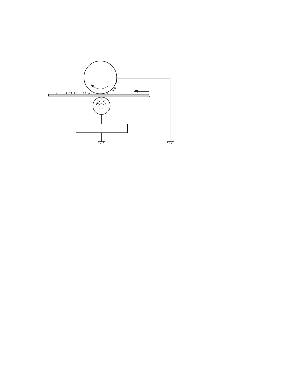
Step 4: Transfer
Transfer roller
Paper
Transfer bias
Photosensitive
drum
The transfer bias is applied to the transfer roller to give the paper a positive charge. The positively charged
paper attracts the negatively charged toner from the photosensitive drum surface.
Figure 1-16 Primary transfer
ENWW Engine laser/scanner system 23
Page 42

Step 5: Separation
Paper
Transfer roller
Static charge eliminator
Photosensitive
drum
Paper
Fuser film
Fuser heater
Pressure roller
The elasticity of the paper and the curvature of the photosensitive drum cause the paper to separate from the
drum surface. The static charge eliminator reduces back side static discharge of the paper for stable paper
feeding and image quality.
Figure 1-17 Separation
Step 6: Fusing
The product uses an on-demand fusing method to fuse the toner image onto the media. The toner image is
permanently aixed to the print media by the heat and pressure. The fusing bias is applied to the pressure
roller to improve image quality.
Figure 1-18 Fusing
Step 7: Drum cleaning
The cleaning blade scrapes the residual toner o the surface of the photosensitive drum and deposits it in the
toner collection box. The drum is now clear and ready for the next image-formation process.
24 Chapter 1 Theory of operation ENWW
Page 43

Figure 1-19 Drum cleaning
Cleaning blade
Residual toner collection box
Photosensitive
drum
Toner cartridges
The printer has one toner cartridge.
Design
The toner cartridge is lled with toner and consists of the following components:
●
Photosensitive drum
●
Developer
●
Primary-charging roller
●
Memory chip
The DC controller rotates the drum motor to drive the photosensitive drum, developing roller, and the
primary-charging roller.
ENWW Engine laser/scanner system 25
Page 44

Figure 1-20 Toner cartridge system
DC controller
Cartridge
E-label
Photosensitive drum
Developer roller
M1
Primary charging
roller
Table 1-11 Toner cartridge functions
Function Supported feature
Toner cartridge presence detection Yes
Toner level detection Yes
Toner cartridge life detection Yes
Toner cartridge mis-installation detection No
Drum discharge No
Transfer cleaning Yes
26 Chapter 1 Theory of operation ENWW
Page 45

Memory chip
The memory chip is non-volatile memory that stores information about the usage of the toner cartridge and
helps protect the customer from counterfeit cartridges. The chip is also used to detect the presence of a
cartridge within the printer or when a cartridge is installed in the wrong slot. The printer reads and writes the
data in the memory chip.
Toner level and cartridge life detection
Toner level detection: The DC controller detects the remaining toner in a cartridge by the optical detection
method and then noties the formatter of the remaining toner level.
Cartridge life detection: The DC controller detects the cartridge life by monitoring the total operating time or
remaining toner level of the toner cartridge. The DC controller determines a cartridge end of life and noties
the formatter when total operating time of the cartridge reaches a specied time or the cartridge runs out of
toner.
Pickup, feed, and delivery system
The DC controller controls the pickup, feed, and delivery system according to commands from the formatter.
The pickup, feed, and delivery system uses a series of rollers to move the paper through the printer.
The pickup, feed, and delivery system consists of the following three functional blocks. The DC controller
controls each block to pick up, feed and deliver the paper.
●
Pickup-and-feed-block: Controls the movement of the paper from each pickup source to the fuser inlet
●
Fuser-and-delivery-block: Controls the movement of the paper from the fuser to the delivery
destination
●
Duplex block: Controls the movement of the paper from the duplex switchback unit to the duplex repickup unit (duplex models only)
ENWW Pickup, feed, and delivery system 27
Page 46

Figure 1-21 Pickup, feed, and delivery system
Duplex paper path
Simplex paper path
Duplex block
Pickup-and-feed block
Fuser-and-delivery block
Table 1-12 Pickup, feed, and delivery system functions
Function Supported feature
Cassette media size detection No
Cassette media presence detection Yes
Cassette media level detection No
28 Chapter 1 Theory of operation ENWW
Page 47

Table 1-12 Pickup, feed, and delivery system functions (continued)
PS1a
PS2a
PS4
PS13
PS2
PS3
PS1
Function Supported feature
Cassette lift-down control No
Cassette multiple-feed prevention mechanism Yes
Multipurpose tray media presence detection Yes
Multipurpose tray media width detection No
Multipurpose tray last-media detection No
Skew-feed prevention mechanism Yes
Loop control No
Media detection No
OHT detection No
Image leading edge positioning Yes
Media length detection Yes
Media width detection Yes
Pressure roller pressure release control No
Output bin media-full detection Yes
Automatic delivery Yes
Duplex switchback control (duplex models only) Yes
Duplex feed control (duplex models only) Yes
Sensors and switches
The following gure shows the sensors and switches for the pickup, feed, and delivery system.
Figure 1-22 Sensors and switches for the pickup, feed, and delivery system
ENWW Pickup, feed, and delivery system 29
Page 48

Table 1-13 Photo sensors and switches
Abbreviation Component
SR1a Media width sensor
SR2b Duplex feed sensor (duplex models only)
SR1 Cassette media out sensor
SR2 TOP sensor
SR3 Multipurpose tray media out sensor
SR4 Output bin media-full sensor
SR13 Fuser output sensor
30 Chapter 1 Theory of operation ENWW
Page 49

Motors, clutches, and solenoids
CL1
SL3
M1
SL2
SL1
The following gure shows the motors, clutches, and solenoids for the pickup, feed, and delivery system.
Figure 1-23 Motors, solenoids, and clutches
Table 1-14 Motors, solenoids, and clutches
Abbreviation Component
M1 Fuser motor
SL1 Cassette pickup solenoid
SL2 Multipurpose tray pickup solenoid
SL3 Duplex switchback solenoid (duplex models only)
CL1 Duplex re-pickup clutch (duplex models only)
Jam detection/prevention
The printer uses the following sensors to detect the paper as it moves through the paper path and to report
to the DC controller if the paper has jammed.
●
Top of page (TOP) sensor (SR2)
●
Media width sensor (SR1a)
●
Fuser output sensor (SR13)
●
Duplex feed sensor (SR2a)
ENWW Pickup, feed, and delivery system 31
Page 50

Figure 1-24 Jam detection sensors
PS432
PS13
PS2a
PS2
PS1a
PS11
Duplex paper path
Simplex paper path
The printer determines that a jam has occurred if one of these sensors detects paper at an inappropriate
time. The DC controller stops the print operation and noties the formatter.
Table
1-15 Jams that the printer detects
Jam Supported feature
No pick jam 1 Yes
No pick jam 2 Yes
No pick jam 3 Yes
No pick jam 4 No
Pickup stay jam 1 Yes
Pickup stay jam 2 No
Pickup stay jam 3 No
Pickup stay jam 4 No
Fuser delivery delay jam 1 Yes
32 Chapter 1 Theory of operation ENWW
Page 51

Table 1-15 Jams that the printer detects (continued)
Jam Supported feature
Fuser delivery delay jam 2 No
Fuser delivery delay jam 3 No
Fuser delivery delay jam 4 No
Fuser delivery stay jam 1 Yes
Fuser delivery stay jam 2 No
Fuser delivery stay jam 3 No
Fuser delivery stay jam 4 No
Residual paper jam 1 Yes
Residual paper jam 2 Yes
Residual paper jam 3 No
Residual paper jam 4 No
Door open jam 1 Yes
Door open jam 2 No
Door open jam 3 No
Door open jam 4 No
Fuser wrap jam1 Yes
Fuser wrap jam2 Yes
Fuser wrap jam3 No
Fuser wrap jam4 No
Duplex switchback jam1 No
Duplex switchback jam2 No
Duplex switchback jam3 No
Duplex switchback jam4 No
Duplex re-pickup jam 1 Yes
Duplex re-pickup jam 2 No
Duplex re-pickup jam 3 No
Duplex re-pickup jam 4 No
Delivery delay jam 1 No
Delivery delay jam 2 No
Delivery delay jam 3 No
Delivery delay jam 4 No
Delivery stay jam 1 No
Delivery stay jam 2 No
ENWW Pickup, feed, and delivery system 33
Page 52

Table 1-15 Jams that the printer detects (continued)
Jam Supported feature
Delivery stay jam 3 No
Delivery stay jam 4 No
Multiple feed jam 1 No
Multiple feed jam 2 No
Multiple feed jam 3 No
Multiple feed jam 4 No
34 Chapter 1 Theory of operation ENWW
Page 53

Paper feeder (optional Tray 3)
This section describes the paper feeder (optional Tray 3).
Basic operation
The paper feeder is optionally installed at bottom of the printer. It picks up the print media and feeds it to the
printer. The paper DC controller controls the operational sequence of the paper feeder.
Paper path
The gure below shows the optional Tray 3 paper path.
Figure 1-25 Optional Tray 3 paper path
Paper feeder controller
The gure below shows the paper feeder controller block diagram. The table in this section describes the
paper feeder electrical components.
ENWW Paper feeder (optional Tray 3) 35
Page 54

Figure 1-26 Paper feeder controller
DC controller
Paper feeder controller
Motor
550-sheet paper feeder
+24VD
+3.3VB
Solenoid
Clutch
Switch
Photointerruptor
Table 1-16 Electrical component list, paper feeder
Component type Abbreviation Component name
Motor M5 Lifter motor
Solenoid SL4 Cassette pickup solenoid
Clutch CL2 Feed clutch (Note)
Switch SW3 Cassette detection switch
Photointerrupter PS460 Media surface sensor
PS461 Cassette media out sensor
Motor control
The paper feeder uses one motor for the cassette lift-up operation.
Table
1-17 Motors, paper feeder
Component name Components driven
M5
1
The paper feeder does not detect lifter motor failures.
Lifter motor
1
Pickup and feed operation
The paper feeder picks up the sheet of paper one by one in the paper feeder cassette and feeds it to the
printer.
Electrical components, pickup and feed
Lifts up the cassette
The gure below shows the paper feeder electrical components. The table in this section describes the
electrical components.
36 Chapter 1 Theory of operation ENWW
Page 55

Figure 1-27 Electrical components, pickup and feed
SL4
M1
M5
SW3
PS461
PS460
Table 1-18 Electrical components, pickup and feed
Abbreviation Component name
M1
Fuser motor
1
M5 Lifter motor
SL4 Cassette pickup solenoid
SW3 Cassette detection switch
PS460 Media surface sensor
PS461 Cassette media out sensor
1
This motor is located in the printer.
Other functions
The paper feeder has the following pickup and feed functions.
Table
1-19 Other functions, paper feeder
Function Supported feature
Cassette lift-up control Yes
Cassette presence detection Yes
Cassette media size detection No
Cassette media stack surface detection Yes
Cassette media out detection Yes
Cassette media level detection No
Multiple-feed prevention Yes
Automatic delivery Yes
ENWW Paper feeder (optional Tray 3) 37
Page 56

Jam detection
The DC controller in the printer detects jams during the paper feeder pickup and feed operation. See Jam
detection/prevention on page 31.
38 Chapter 1 Theory of operation ENWW
Page 57

2 Solve problems
●
For additional service and support
●
Solve problems checklist
●
Troubleshooting process
●
Tools for troubleshooting
●
Clear paper jams
●
Solve paper-handling problems
●
Solve image quality problems
●
Clean the printer
●
Solve performance problems
●
Solve connectivity problems
●
Service mode functions
●
Solve fax problems (fax models only)
●
Solve email problems (M426, M427 printes)
●
Manually update the rmware
ENWW 39
Page 58

For additional service and support
HP service personnel, go to the Service Access Work Bench (SAW) at http://h41302.www4.hp.com/km/saw/
home.do.
Channel partners, go to HP Channel Services Network (CSN) at https://h30125.www3.hp.com/hpcsn.
At these locations, nd information on the following topics:
●
Install and congure
●
Printer specications
●
Up-to-date control panel message (CPMD) troubleshooting
●
Solutions for printer issues and emerging issues
●
Remove and replace part instructions and videos
●
Service advisories
●
Warranty and regulatory information
To access HP PartSurfer information from any mobile device, go to http://partsurfermobile.hp.com/ or scan
the Quick Response (QR) code below.
40 Chapter 2 Solve problems ENWW
Page 59

Solve problems checklist
●
Solve problems checklist
Solve problems checklist
If the printer is not correctly functioning, complete the steps (in the order given) in the following checklist. If
the printer fails a checklist step, follow the corresponding troubleshooting suggestions for that step. If a
checklist step resolves the problem, skip the remaining checklist items.
1. Make sure that the printer is set up correctly.
a. Press the power button to turn on the printer or to deactivate the Auto-O mode.
b. Check the power-cable connections.
c. Make sure that the line voltage is correct for the printer power conguration. See the label that is
on the printer for voltage requirements. If you are using a power strip and its voltage is not within
specications, plug the printer directly into the wall. If it is already plugged into the wall, try a
dierent outlet.
2. Check the cable connections.
a. Check the cable connection between the printer and the computer. Make sure that the connection
is secure.
b. Make sure that the cable itself is not faulty, by using a dierent cable if possible.
c. Check the network connection: Make sure that the network light is lit. The network light is next to
the network port on the back of the printer.
If the printer remains unable to connect to the network, uninstall and then reinstall the printer. If
the error persists, contact a network administrator.
3. Check to see if any messages appear on the control panel.
4. Make sure that the paper you are using meets specications.
5. Make sure that the paper is loaded correctly in the input tray.
6. Make sure that the printer software is installed correctly.
7. Verify that you have installed the printer driver for this printer, and that you are selecting this printer
from the list of available printers.
8. Print a conguration page.
a. 2-line control panels: On the printer control panel, press the OK button.
Touchscreen control panels: From the Home screen on the printer control panel, touch the Setup
button.
b. Open the Reports menu.
c. Select Conguration Report.
ENWW Solve problems checklist 41
Page 60

After printing the conguration page, check the following:
a. If the page does not print, verify that the input tray contains paper and that the paper is properly
loaded.
b. Make sure that the toner cartridge is installed correctly.
c. If the page jams in the printer, clear the jam.
d. If the print quality is unacceptable, complete the following steps:
●
●
9. Print a small document from a dierent program that has printed in the past. If this solution works, then
the problem is with the program you are using. If this solution does not work (the document does not
print), complete these steps:
a. Try printing the job from another computer that has the printer software installed.
b. Check the cable connection. Direct the printer to the correct port, or reinstall the software,
selecting the connection type you are using.
Print the menu map
To more easily navigate individual settings, print a report of the complete printer menus.
Verify that the print settings are correct for the paper you are using.
Solve print-quality problems.
1. 2-line control panels: On the printer control panel, press the OK button.
Touchscreen control panels: From the Home screen on the printer control panel, touch the Setup
button.
2. Open the Reports menu.
3. Select Menu Structure.
Print a conguration page
Print a conguration page to test the printer.
1. 2-line control panels: On the printer control panel, press the OK button.
Touchscreen control panels: From the Home screen on the printer control panel, touch the Setup
button.
2. Open the Reports menu.
3. Select Conguration Report.
42 Chapter 2 Solve problems ENWW
Page 61

Print the service page (includes the event log)
Printing the service page provides a list of printer settings that might be helpful in the troubleshooting
process, as well as the event log, which stores the last 10 error events that the printer experienced.
1. 2-line control panels: On the printer control panel, press the OK button.
Touchscreen control panels: From the Home screen on the printer control panel, touch the Setup
button.
2. Open the Reports menu.
3. Select the Service Page option to print the report.
The event log is located in the lower right-hand corner of the service page.
Print the demo page
Print a product demo page.
2-line control panels
▲
With the printer in the Ready state, press the OK button and the Cancel button at the same time.
Touchscreen control panels
1.
From the Home screen on the printer control panel, touch the Setup button.
2. Open the Reports menu.
3. Select Demo Page.
ENWW Solve problems checklist 43
Page 62

Troubleshooting process
●
Determine the problem source
●
Power subsystem
●
Control panel checks
Determine the problem source
When the printer malfunctions or encounters an unexpected situation, the printer control panel alerts the
user to the situation. This section contains a pre-troubleshooting checklist to
of the problem. Use the troubleshooting owchart to help diagnose the root cause of the problem. The
remainder of this chapter provides steps for correcting problems.
●
Use the troubleshooting owchart to pinpoint the root cause of hardware malfunctions. The owchart
provides guides to the sections of this chapter that contain steps to correct the malfunction.
Before beginning any troubleshooting procedure, check the following issues:
●
Are supply items within their rated life?
●
Does the conguration page reveal any conguration errors?
NOTE: The customer is responsible for checking supplies and for using supplies that are in good condition.
lter out many possible causes
Pre-troubleshooting checklist
The following table includes basic questions to ask the customer to quickly help dene the problem(s).
General topic Questions
Environment
Media
Input trays
●
Is the printer installed on a solid, level surface (+/- 1°)?
●
Is the power-supply voltage within ± 10 volts of the specied power source?
●
Is the power-supply plug inserted in the printer and the outlet?
●
Is the operating environment within the specied parameters?
●
Is the printer exposed to ammonia gas, such as that produced by diazo copiers or
oice cleaning materials?
NOTE: Diazo copiers produce ammonia gas as part of the copying processes.
Ammonia gas (from cleaning supplies or a diazo copier) can have an adverse eect
on some printer components (for example, the toner cartridge OPC).
●
Is the printer exposed to direct sunlight?
●
Does the customer use only supported media?
●
Is the media in good condition (no curls, folds, or distortion)?
●
Is the media stored correctly and within environmental limits?
●
Is the amount of media in the tray within specications?
●
Is the media correctly placed in the tray?
●
Are the paper guides aligned with the stack?
●
Is the tray correctly installed in the printer?
44 Chapter 2 Solve problems ENWW
Page 63

General topic Questions
Toner cartridge
Transfer unit and fuser
Covers
Condensation
Miscellaneous
●
Is the toner cartridge installed correctly?
●
Are the transfer unit and fuser installed correctly?
●
Is the toner cartridge door closed?
●
Does condensation occur following a temperature change (particularly in winter
following cold storage)? If so, wipe aected parts dry or leave the printer on for 10
to 20 minutes.
●
Was a toner cartridge opened soon after being moved from a cold to a warm room?
If so, allow the toner cartridge to sit at room temperature for 1 to 2 hours.
●
Check for and remove any non-HP components (toner cartridges, memory
modules, and EIO cards) from the printer.
●
If the hardware or software conguration has not changed or the problem is not
associated with any specic software, see the complete service manual for this
printer.
●
Remove the printer from the network and ensure that the failure is associated with
the printer before beginning troubleshooting.
●
For any print-quality issues, calibrate the printer.
ENWW Troubleshooting process 45
Page 64

Determine the problem source
The following table includes basic questions to ask the customer to quickly help dene the problem or
problems.
General topic Questions
Environment
Paper
Input tray
Supplies
●
Is the printer installed on a solid, level surface (± 1°)?
●
Is the power-supply voltage within ± 10 volts of the specied power source?
●
Is the power-supply plug inserted in the printer and the outlet?
●
Is the operating environment within the specied parameters?
●
Is the printer exposed to ammonia gas, such as that produced by diazo copiers or
oice cleaning materials?
NOTE: Diazo copiers produce ammonia gas as part of the coping processes.
Ammonia gas (from cleaning supplies or a diazo copier) can have an adverse aect
on some printer components (for example, the toner cartridge imaging drum).
●
Is the printer exposed to direct sunlight?
●
Does the customer use only supported paper?
●
Is the paper in good condition (no curls, folds, or distortion)?
●
Is the paper stored correctly and within environmental limits?
●
Is the amount of paper in the tray within specications?
●
Is the paper correctly placed in the tray?
●
Are the paper guides aligned with the stack?
●
Is the toner cartridge installed correctly and rmly seated?
Transfer roller and fuser
Covers
Condensation
Miscellaneous
●
Has the sealing tape been removed from the toner cartridge?
●
Is the toner cartridge within its estimated life? (Check the supplies status page.)
●
Are the transfer roller and fuser installed correctly?
●
Are the front and rear doors rmly closed?
●
Does condensation occur following a temperature change (particularly in winter
following cold storage)? If so, wipe aected parts dry or leave the printer on for 90
to 120 minutes.
●
Was a toner cartridge opened soon after being moved from a cold to a warm room?
If so, allow the toner cartridge to sit at room temperature for 1 to 2 hours.
●
Check for and remove any non-HP components (for example, a toner cartridge)
from the printer.
●
Remove the printer from the network and make sure that the failure is with the
printer before beginning troubleshooting.
46 Chapter 2 Solve problems ENWW
Page 65

Power subsystem
Power-on checks
When you turn on the printer, if it does not make any sound or if the control-panel display is blank, check the
following items:
●
Verify that the printer is plugged directly into an active electrical outlet that has the correct voltage. Do
not plug the printer into a surge protector or power strip.
●
Verify that the on/o switch is in the on position.
●
Verify that the formatter is seated and operating correctly.
●
Remove any HP Jetdirect accessories or other devices, and then try to turn the printer on again.
●
Make sure that the control-panel display is connected.
●
Check the two fuses on the power supply.
●
If necessary, replace the power supply.
●
If necessary, replace the DC controller.
Control panel checks
The printer includes diagnostic tests for the control panel. This mode allows for troubleshooting issues with
the LEDs (2-line control panels), display, and the buttons.
1. Open the secondary service menu.
2-line control panels
a. From the printer control panel, press the OK button.
b. Press and hold the left arrow button.
c. Press the Cancel button.
d. Press the OK button to reopen the Setup menu.
e. Scroll to the 2ndary Service menu, and then press the OK button.
Touchscreen control panels
a.
From the Home screen on the printer control panel, touch the Setup button.
b.
Touch the space between the Home and Help buttons.
c.
Touch the Back button.
d.
Touch the Setup button.
e. Scroll to and touch the 2ndary Service menu.
2. Select one of the following tests:
ENWW Troubleshooting process 47
Page 66

●
LED test: Test the LED lights on 2-line control panels. The touchscreen control panels do not have
any LEDs.
●
Display Test: Test the control panel display.
●
Button Test: Test the control panel buttons.
48 Chapter 2 Solve problems ENWW
Page 67

Tools for troubleshooting
The section describes the tools that can help solve problems with the printer.
Component diagnostics
LED diagnostics
Network LEDs (network models only)
The onboard network solution has two network port LEDs. When the printer is connected to a properly
working network through a network cable, the yellow LED indicates network activity, and the green LED
indicates the link status. A blinking yellow LED indicates network traic. If the green LED is o, a link has
failed.
For link failures, check all of the network cable connections. In addition, you can try to manually congure the
network card link speed setting by using the printer control-panel.
Change the Link Speed setting on an LCD control panel
1. At the printer control panel, press the OK button to open the menus.
2. Select the Network Setup menu, and then press the OK button.
3. Select the Link Speed item, and then press the OK button.
4. Select the appropriate link speed, and then press the OK button.
Change the Link Speed setting on a touchscreen control panel
1.
From the Home screen on the printer control panel, touch the Setup button.
2. Scroll to, and then touch the Network Setup menu.
3. Scroll to, and then touch Link Speed item.
4. Touch the appropriate link speed.
Control panel LEDs
The state of the Ready light and Attention light on the printer signal the printer status. The following table
outlines the possible control-panel light states.
Printer state Ready light state Attention light state
Initializing Blinking Blinking
Ready On O
Receiving data/processing job or cancelling
job
Error message O Blinking
Fatal error (49 or 79 error)
1
The printer will power o and then power on after one of these errors occurs.
1
Blinking O
On On
ENWW Tools for troubleshooting 49
Page 68

Engine diagnostics
Engine test
When the engine test is performed, a test page with horizontal lines prints if the engine is functioning
correctly.
To perform the test do one of the following (with the printer in the Ready state):
●
Simplex printers: Depress and hold the cartridge door release button, and then open and shut the
cartridge door three times within a three second time period. A single-sided test page prints.
●
Duplex printers: Depress and hold the cartridge door release button, and then open and shut the
cartridge door four times within a three second time period. A double-sided test page prints.
NOTE: A single-sided test page prints if the duplex function is disabled.
50 Chapter 2 Solve problems ENWW
Page 69

Diagrams
13
15
14
21
17
18
20
19
2
1
3
4
5 6 7
8 9
11
12
10
16
Use the diagrams in this section to identify printer components.
Diagrams: Block diagrams
Cross-sectional view of printer
Figure 2-1 Cross-sectional view of printer
Item Description Item Description
1 Fuser output roller 12 Feed roller
2 Duplex apper (duplex models only) 13 Cassette feed roller
3 Output roller 14 Cassette separation roller
4 Fuser lm 15 Cassette pickup roller
5 Fuser 16 Duplex re-pickup roller (duplex models only)
6 Photosensitive drum 17 Registration roller
7 Laser scanner assembly 18 Cassette
8 Toner cartridge 19 Transfer roller
9 Registration shutter 20 Duplex feed roller (duplex models only)
10 Multipurpose tray pickup roller 21 Pressure roller
11 Multipurpose tray separation pad
ENWW Tools for troubleshooting 51
Page 70

Cross-sectional view of 550–sheet paper feeder
2
1
3
4
5
Figure 2-2 Cross-sectional view of 500–sheet paper feeder
Item Description Item Description
1 Cassette 4 Feed roller
2 Cassette pickup roller 5 Cassette separation roller
3 Cassette feed roller
52 Chapter 2 Solve problems ENWW
Page 71

Diagrams: Printed circuit assembly (PCA) connector locations
J4
J7
J6
J8
J1
J9
J2
J10
J5
J3
●
Diagrams: DC controller connections
●
Paper feeder controller PCA
Diagrams: DC controller connections
Each of the connections on the DC controller PCA is indicated in the following gure.
Figure 2-3 DC controller PCA connectors
Table 2-1 DC controller connectors
Item Description Item Description
J1 Low-voltage power supply assembly J7 Media-width sensor
J2 High-voltage power supply PCA Duplex feed sensor (duplex models only)
J3 Formatter TOP sensor
J4 Laser assembly J8 Cassette media out sensor
J5 Connector PCA J9 Multipurpose tray media out sensor
J6 Output bin media-full sensor J10 Memory tag (E-label)
Fuser output sensor Loop sensor
Thermistor
ENWW Tools for troubleshooting 53
Page 72
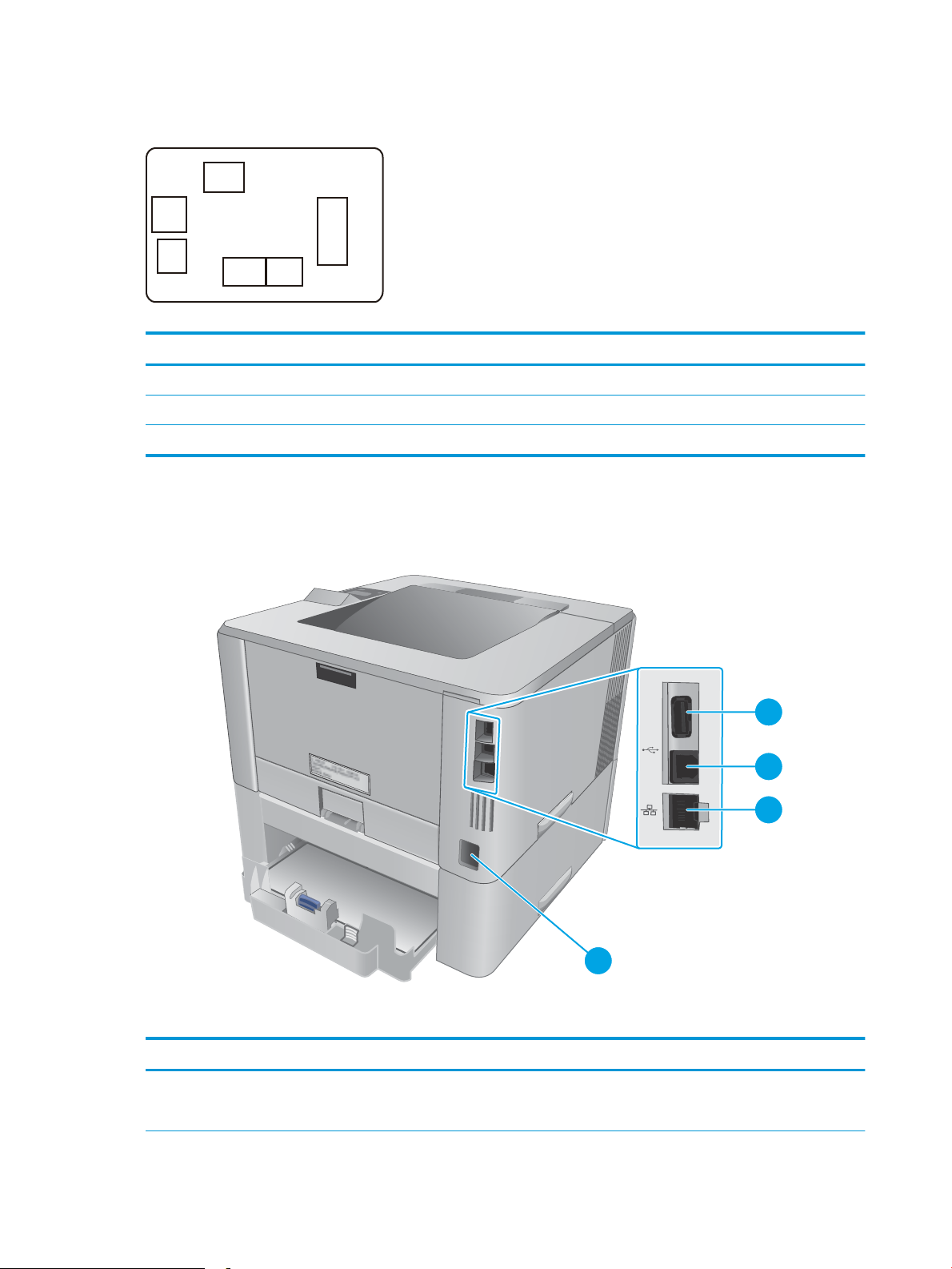
Paper feeder controller PCA
J603
J601
J600
J605
J602
J604
4
1
2
3
Figure 2-4 Paper feeder controller PCA connectors
Table 2-2 Paper feeder controller PCA connectors
Item Description Item Description
J600 Printer J603 Media surface sensor
J601 Cassette detection switch J604 Cassette pickup solenoid
J602 Cassette media out sensor J605 Lifter motor
Diagrams: External plug and port locations
Figure 2-5 M402, M403 external plugs and ports locations
Table
2-3 M402, M403 external plugs and ports
Item Description
1 USB port (for job storage and private printing)
NOTE: This port might be covered
54 Chapter 2 Solve problems ENWW
Page 73

Table 2-3 M402, M403 external plugs and ports (continued)
6
1
2
3
5
4
Item Description
2 USB interface port
3 Ethernet port
4 Power connection
Figure 2-6 M426, M427 external plug and port locations
Table 2-4 M426, M427 external plugs and ports
Item Description
1 USB port (for job storage and private printing)
NOTE: This port might be covered
2 USB interface port
3 Ethernet port
4 Telephone “line out” port (for attaching an extension phone, answering machine, or other device)
5 Fax “line in” port (for attaching the fax phone line to the printer)
6 Power connection
ENWW Tools for troubleshooting 55
Page 74

Diagrams: Locations of major components
1
2
3
Major components (printer base)
Figure 2-7 Major components (printer base)
Table 2-5 Major components (printer base)
Item Description
1 Fuser
2 Registration assembly
3 Laser/scanner assembly
56 Chapter 2 Solve problems ENWW
Page 75

Motor and fan
1
2
Figure 2-8 Motor and fan
Table 2-6 Motor and fan (printer base)
Item Description
1 Fuser motor (M1)
2 Main fan (FM1)
ENWW Tools for troubleshooting 57
Page 76
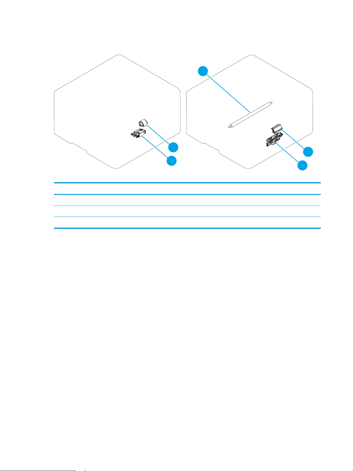
Rollers and pads (printer base)
1
2
3
4
5
Figure 2-9 Rollers and pads (printer base)
Table 2-7 Rollers and pads (printer base)
Item Description Item Description
1 Transfer roller 4 MP tray pickup roller
2 MP tray separation pad 5 Pickup roller assembly
3 Separation roller assembly
58 Chapter 2 Solve problems ENWW
Page 77

PCAs (printer base)
1
2
3
Figure 2-10 Main PCAs (printer base)
Table 2-8 Main PCAs (printer base)
Item Description Item Description
1 High-voltage power supply assembly Not shown Formatter PCA
2 DC controller PCA Not shown Wireless PCA (wireless models only)
3 Low-voltage power supply assembly Not shown Fax PCA (fax models only)
ENWW Tools for troubleshooting 59
Page 78

Diagrams: Timing chart
Timing chart two consecutive prints on LTR paper
12 Developing bias
13 T ransfer bias
14 Main f an (FM1)
9 Fuser motor (M1)
10 Fus er heater
11 Pr imary charging bias
6 BD signal
7 Scanner motor (M3)
4TOP sensor (PS2)
5 Fuser output sensor (PS13)
LSTR
STBY
1 Print command
2 Cassette pick up solenoid (SL1)
PRINT
WAIT
STBY
INTR
Power ON
Figure 2-11 General timing chart
60 Chapter 2 Solve problems ENWW
Page 79

Diagrams: Circuit diagrams
A
6 5 4 3
2
1
B
C
D
M
SL
12345 123
21
TP
123
CL
SL
M
SL
M
SL
CL
123
1
13
4
2
3
5
6
7
8
9
10
11
12
14
15
16
17
18
19
20
21
22
22
21
20
19
18
17
16
15
14
12
11
10
9
13
8
7
6
5
3
2
4
1
SGND
/VDO1
VDO1
SGND
/VDO2
SGND
VDO2
CLEI
/BDO
SGND
CLEO
GND
PRIACCLK
PRIDCPWM
PRIACPWM
TNR
FANON
FANLOCK
TRPWM
DEVDCSNS
DEVACPWM
DEVACCLK
TRCRNT
TRPCLK
TRNCLK
+5.4V
+24VA
SGND
+24VBSNS
24VCON
345612
J1302A
J507
345612
J1302S
345612
345612
USB PCA
J508
J510
22
8
J503
6
J505
WiFi
+5V
/CPRESET
/CPCLK
CPCLK
CPIN
GND
+3.3V
CPOUT
4
1
2
3
5
6
7
8
4
1
2
3
5
6
4
1
2
3
5
6
8
1
2
7
4
3
5
6
8
J504
J44
123745689
987653421
J33
Contorl panel
(Magic frame)
22
J509
6
J506
SGND
SGND
+3.3VC
+3.3VC
J213
21
H1
12
TP1
SGND
LVPSGND
SGND
+3.3VC
+3.3VC
+24VD
AC-N
AC-H
PS13
21
FU2
2
1
FU1
J4203
J4204
J4202
J4201
J410DH
J410L
J410D
TH1
12
21
12
+3.3VB(GY)
NFCS(BL)
SGND
MAINTH
FSROUTSNS(GN)
SGND(BR)
J407J406
121234
PS4
321
Inlet
SOLD210
SOLD211
LVPS_GND
LVPS_GND
+24VD
+24VD
1234
J203
AC-H
AC-N
J210
J211
231
J212
J207A
J206A
J204A
J205A
J209A
J208A
J207S
J206S
J204S
J205S
10
982345617
J201
12
J501
FANON
FANLOCK
GND
123
J301
FM1
321
J341
1234567891011121314151617
18
123456789
101112131415161718
18
J2
412356789
101112
4123567891011
12
12
J3
LVPS_GND
FREQSNS_LVT
/3.3VCON
RLYD
PWRSAVE2
24VDON
24VD
24VA
FSRD
3.3VA
109
82345617
J1
SGND
MAINTH
FSROUTSNS
FULLSNS
+3.3VB
NFCS
1
234
56
J405
1234
56
J6
TOPSNS(BR)
SGND(W)
+3.3VB(BL)
TAG
MPTPSNS(W)
SGND(BR)
+3.3VB(R)
CSTPSNS(W)
SGND(BR)
+3.3VB(Y)
REFEEDSNS(V)
TOPSNS(GY)
SGND(R)
PWSNSAND(W)
+3.3VB(BR)
J7 J9J8
19
J5
SGND
SGND
SGND
+3.3VB
/LDPWM
/BDI
VDO1
VDO2
/VDO2
SGND
/VDO1
LDCTRL1
LDCTRL0
LDCTRL2
678
9
1011121314
41235
987654321
1314121110
14
J4
12
12
J18
J10
VSS(W)
VIN(BL)
123
4
OPTPLVLSNS(SI)
OPTLIFTMT
+3.3VB
OPTSNSAD
DUPSWBKSL
REFEEDCL
OPTPICKSL(SO)
SGND
PWRLED_ON
PWRLED_PWR
BLMFG
PWRSW
AIRTMP
/BLMACC
/SCNACC
/BLMDEC
CSTSL
MPTSL
/SCNDEC
191817161514131211
10
987653241
13121415161718
19
4235678910
11
1
J4011
J4121
J4122
J4012
J4013
J4123
PS1
PS3
PS1a
PS2b
123
J700
PS2
J4031
J4033
J4032
J7014
J7013
J7012
J7011
J7015
High-voltage
power supply
PCA
DC controller
1234
J802
M3
14
J811
Laser/scanner ass’y
+24VD
PGND
/SCNDEC
/SCNACC
LVPS_GND
+24VD
+24VD
LVPS_GND
1
12
J13B
(REFEEDCL)
+24VD
2
J111B
J13A
2
1
CL1
12
SL3
21
21
SW1LED1
1234
5
J701
1234567
J705
7653214
M1
J13DH
J13L
J13D
1
2
1
2
12
SL1
SL2
12
(CSTSL)
+24VD
+24VD
(MPTSL)
PGND
PGND
+24VD
BLMFG
/BLMDEC
+24VD
/BLMACC
(DUPSWBKSL)
+24VD
+24VD
(REFEEDCL)
+24VD
+3.3VB
SGND
OPTSNSAD
OPTLIFTMT
OPTPLVLSNS
OPTPICKSL
SGND
AIRTMP
PWRSW
PWRLED_ON
PWRLED_PWR
1234
J105
12
J104
J102 J110
1234567121212345
J107 J109
J101
121234567
1234
J106
J103
J111A
1234567
1234567
Connector PCA
21
OPTCSTPSNS(GN)
+3.3VB(Y)
SGND
OPTCSTSNS
+24VD(BR)
+24VD
OPTPICKSL
OPTLIFTMT(W)
SGND(BR)
+3.3VB(V)
OPTPLVLSNS(GN)
SGND(BR)
J691LH
J691D
J691DH
J691L
PS461
PS460
SOLD6121
SOLD6122
J4611
J4612
J4613
J4601
J4602
J4603
SL4
J692DH
J692L
J692D
12
12
12
21
M5
1234567
1
231
21
21212
3
J601
J600
J602
J603J605J604
Paper feeder controller PCA
SW3
2
1
CL1
Low-voltage power supply PCA
Formatter
NFC PCA
Contorl panel
LCD PCA
Contorl panel
SW PCA
Laser PCA
Figure 2-12 General circuit diagram (printer base)
ENWW Tools for troubleshooting 61
Page 80

Advanced conguration with HP Embedded Web Server (EWS) and HP Device
Toolbox (Windows 7)
Use the HP Embedded Web Server to manage printing functions from a computer instead of the printer
control panel.
●
View printer status information
●
Determine the remaining life for all supplies and order new ones
●
View and change tray congurations
●
View and change the printer control-panel menu conguration
●
View and print internal pages
●
Receive notication of printer and supplies events
●
View and change network conguration
The HP Embedded Web Server works when the printer is connected to an IP-based network. The HP
Embedded Web Server does not support IPX-based printer connections. Internet access is not needed to open
and use the HP Embedded Web Server.
When the printer is connected to the network, the HP Embedded Web Server is automatically available.
NOTE: HP Device Toolbox is software used to connect to the HP Embedded Web Server when the printer is
connected to a computer via USB. It is available only if a full installation was performed when the printer was
installed on a computer. Depending on how the printer is connected, some features might not be available.
NOTE: The HP Embedded Web Server is not accessible beyond the network rewall.
Method one: Open the HP Embedded Web Server (EWS) from the Start menu
1. Click the Start button, and then click the Programs item.
2. Click the HP printer group, and then click the HP Device Toolbox item.
Method two: Open the HP Embedded Web Server (EWS) from a Web browser
1. Use one of the following methods to obtain the IP address based on your printer model:
M402, M403
●
On the printer control panel, press the OK button. Open the Network Setup menu, and then select
Show IP Address to display the IP address or host name.
M426, M427
●
From the Home screen on the printer control panel, touch the Connection Information
button, and then touch the Network Connected button or the Network Wi-Fi ON button to
display the IP address or host name.
62 Chapter 2 Solve problems ENWW
Page 81

2. Open a Web browser, and in the address line, type the IP address or host name exactly as it displays on
the printer control panel. Press the Enter key on the computer keyboard. The EWS opens.
NOTE: If the Web browser displays a There is a problem with this website’s security certicate
message when attempting to open the EWS, click Continue to this website (not recommended).
Choosing Continue to this website (not recommended) will not harm the computer while navigating
within the EWS for the HP printer.
Tab or section Description
Home tab
Provides printer, status, and
conguration information.
System tab
Provides the ability to congure the
printer from your computer.
●
Device Status: Shows the printer status and shows the approximate percent life
remaining of HP supplies.
●
Supplies Status: Shows the approximate percent life remaining of HP supplies. Actual
supply life remaining can vary. Consider having a replacement supply available to install
when print quality is no longer acceptable. The supply does not need to be replaced
unless the print quality is no longer acceptable.
●
Device Conguration: Shows the information found on the printer conguration page.
●
Network Summary: Shows the information found on the printer network conguration
page.
●
Reports: Print the conguration and supplies status pages that the printer generates.
●
Job Storage Log: Shows a summary of all jobs stored in the printer memory.
●
Event Log: Shows a list of all printer events and errors.
●
Device Information: Provides basic printer and company information.
●
Paper Setup: Change the default paper-handling settings for the printer.
●
Print Quality: Change the default print-quality settings for the printer.
●
Energy Settings: Change the default times for entering Sleep/Auto O mode or
automatic shut down.
●
Job Storage Setup: Congure the job storage settings for the printer.
●
Print Density: Change the print density of contrasts, highlights, midtones, and shadows
●
Paper Types: Congure print modes that correspond to the paper types that the printer
accepts.
●
System Setup: Change the system defaults for the printer.
●
Supply Settings: Change the settings for Cartridge is low alerts and other supplies
information.
●
Service: Perform the cleaning procedure on the printer.
●
Save and Restore: Save the current settings for the printer to a le on the computer. Use
this le to load the same settings onto another printer or to restore these settings to this
printer at a later time.
●
Administration: Set or change the printer password. Enable or disable printer features.
NOTE: The System tab can be password-protected. If this printer is on a network, always
consult with the administrator before changing settings on this tab.
ENWW Tools for troubleshooting 63
Page 82

Tab or section Description
Print tab
Provides the ability to change default
print settings from your computer.
Fax tab
(M426, M427 models only)
Scan tab
(M426, M427 models only)
●
Printing: Change the default printer print settings, such as number of copies and paper
orientation. These are the same options that are available on the control panel.
●
PCL5c: View and change the PCL5c settings.
●
PostScript: Turn o or on the Print PS Errors feature.
●
Receive Options: Congure how the printer handles incoming faxes.
●
Phone Book: Add or delete entries in the fax phone book.
●
Junk Fax List: Set fax numbers to block from sending faxes to the printer.
●
Fax Activity Log: Review recent fax activity for the printer.
Congure the Scan to Network Folder and Scan to E-mail features.
●
Network Folder Setup: Congure folders on the network to which the printer can save a
scanned le.
●
Scan to E-mail Setup: Begin the process to set up the Scan to E-mail feature.
●
Outgoing E-mail Proles: Set an email address that will appear as the “from” address for
all emails sent from the printer.
●
Default SMTP Conguration: Congure the SMTP Server information.
●
E-mail Address Book: Add or delete entries in the email address book.
●
Network Contacts Setup: Congure the printer to connect to a network address book.
●
Networking tab
(Network-connected printers only)
Provides the ability to change
network settings from your
computer.
HP Web Services tab Use this tab to set up and use various Web tools with the printer.
Network administrators can use this tab to control network-related settings for the printer
when it is connected to an IP-based network. It also allows the network administrator to set up
Wi-Fi Direct functionality. This tab does not appear if the printer is directly connected to a
computer.
Internal print-quality test pages
Clean the paper path
During the printing process, paper, toner, and dust particles can accumulate inside the printer. Over time, this
buildup can cause print-quality problems such as toner specks or smearing. This printer has a cleaning mode
that can correct and prevent these types of problems.
Clean the paper path (LCD control panel)
1. On the printer control panel, press the OK button to open the menus.
2. Open the following menus:
E-mail Options: Congure a default subject line and body text. Congure default scan
settings for emails.
64 Chapter 2 Solve problems ENWW
Page 83

●
Service
●
Cleaning Page
3. Load plain paper in Tray 1, and then press the OK button to start the cleaning process.
Wait until the process is complete. Discard the page that prints.
Clean the paper path (touchscreen control panel)
1.
From the Home screen on the printer control panel, touch the Setup button.
2. Touch the Service menu.
3. Touch the Cleaning Page button.
4. Load plain letter or A4 paper when you are prompted.
5. Touch the OK button to begin the cleaning process.
Wait until the process is complete. Discard the page that prints.
Print the conguration page
The conguration page lists current printer settings and properties. This page also contains a status log
report. To print a conguration page, complete one of the following procedures.
Print the conguration page from an LCD control panel
1. On the printer control panel, press the OK button to open the menus.
2. Use the arrow buttons to select the Reports menu, and then press the OK button.
3. Use the arrow buttons to select the Conguration Report item, and then press the OK button to print the
report.
Print the conguration page from a touchscreen control panel
1.
From the Home screen on the printer control panel, touch the Setup button.
2. Touch the Reports menu.
3. Touch the Conguration Report button to print the report.
ENWW Tools for troubleshooting 65
Page 84

Print-quality troubleshooting tools
Repetitive image defect ruler
Defects on printer rollers can cause image defects to appear at regular intervals on the page, corresponding
to the circumference of the roller that is causing the defect. Measure the distance between defects that recur
on a page (See Use a ruler to measure between repetitive defects on page 66). Use the following table or
the repetitive-defect ruler to determine which roller is causing the defect. To resolve the problem, try cleaning
the roller rst. If the roller remains dirty after cleaning or if it is damaged, replace the part that is indicated in
the following table.
CAUTION: Do not use solvents or oils to clean rollers. Instead, rub the roller with a lint-free cloth. If dirt is
diicult to remove, rub the roller with a lint-free cloth that has been dampened with water.
NOTE: The following table replaces the graphical repetitive defect ruler. You can make your own ruler by
using these measurements. For the most accurate results, use a metric ruler.
Table 2-9 Repetitive defects
Component Distance between defects
Primary charging roller
Developer roller
Transfer roller 39 mm (1.54 in)
1
1
28 mm (1.10 in)
31 mm (1.22 in)
Registration roller 43 mm (1.69 in)
Cassette separation roller 44 mm (1.73 in)
Cassette pickup roller
Cassette feed roller
Fuser lm 57 mm (2.24 in)
Pressure roller
Photosensitive drum
1
The primary charging roller, photosensitive drum and developer roller cannot be cleaned as these rollers are located inside the toner
cartridge. If any of these rollers are indicated, replace the toner cartridge.
2
The primary fuser sleeve unit or pressure roller cannot be cleaned because they are internal assemblies in the fuser. If one of these
assemblies is causing the defect, replace the fuser.
2
1
Use a ruler to measure between repetitive defects
The gures in this section shows color repetitive defect pages. However, the process for measuring repetitive
defects is valid for mono pages.
1. Identify a repetitive defect on the page.
TIP: Print a cleaning page to see if that resolves the defect.
50 mm (1.97 in)
63 mm (2.48 in)
75 mm (2.95 in)
66 Chapter 2 Solve problems ENWW
Page 85

The example pages below show the following types of repetitive defects.
1 2
3
NOTE: These are examples only, other types of repetitive defects might appear on a page.
●
Lines (callout 1)
●
Smudges (callout 2)
●
Dots or spots (callout 3)
Figure 2-13 Examples of repetitive defects
ENWW Tools for troubleshooting 67
Page 86

2. Position a metric ruler on the page with the “zero” ruler mark at one occurrence of the defect (callout 1).
1
1
Figure 2-14 Place the ruler on the page
3. Locate the next occurrence of the defect (callout 1).
Figure 2-15 Locate the next repetitive defect
68 Chapter 2 Solve problems ENWW
Page 87

4. Measure the distance (in millimeters) between the two occurrences (callout 1), and then use Table 2-9
1
Repetitive defects on page 66 to determine the defective assembly.
TIP: Always measure from and to the same point on the defects. For example, if the ruler is “zeroed”
at the top edge of a defect, measure to the top edge of the next occurrence of that defect.
Figure 2-16 Determine the defective assembly
ENWW Tools for troubleshooting 69
Page 88

Control panel menus
●
HP Web Services menu
●
Reports menu
●
Quick Forms menu
●
USB Flash Drive menu
●
System Setup menu
●
Service menu
●
Network Setup menu
HP Web Services menu
Use the HP Web Services menu to set up the HP Web Services features.
Menu item Description
Print Information Sheet Prints a report that instructs the user how to set up the HP Web Services features.
Display Address Displays the printer email address.
Turn ePrint On/O Enables or disables the printer HP ePrint functionality.
Turn Apps On/O Enables or disables the printer HP Web Services applications.
Enable Web Services Enables the HP Web Services features.
Remove Services Removes the HP Web Services features from the printer.
Clear Apps History Deletes the stored history of the printer HP Web Services applications.
Proxy Settings Allows you to enter proxy server information for the printer internet connection.
Reports menu
Use the Reports menu to print reports that provide information about the printer.
Menu item Description
Demo Page Prints a sample page that demonstrates print quality.
Menu Structure Prints a map of the control panel-menu layout. The active settings for each menu are
Conguration Report Prints a list of all the printer settings. Includes network information when the printer is
listed.
connected to a network.
70 Chapter 2 Solve problems ENWW
Page 89

Menu item Description
Supplies Status Prints the status for each toner cartridge, including the following information:
●
Estimated percentage of cartridge life remaining
●
Approximate pages remaining
●
Part numbers for HP toner cartridge
●
Number of pages printed
●
Information about ordering new HP toner cartridges and recycling used HP toner
cartridges
Network Summary Prints a list of all printer network settings
Usage Page Prints a page that lists PCL pages, PCL 6 pages, PS pages, pages that were jammed or
mispicked in the printer, and reports the page count
PCL Font List Prints a list of all the PCL fonts that are installed
Prints a list of all the PostScript (PS) fonts that are installed
PCL6 Font List Prints a list of all the PCL6 fonts that are installed
Service Page Provides information on supported paper types, copy settings, and other miscellaneous
settings that are not on the conguration page
Quick Forms menu
Menu item Sub-menu item Description
Notebook Paper Narrow Rule
Graph Paper 1/8 inch
Checklist 1 Column
Music Paper Portrait
USB Flash Drive menu
Print Documents
Prints pages that have preprinted lines
Wide Rule
Child Rule
Prints pages that have preprinted graph lines
5 mm
Prints pages that have preprinted lines with check boxes
2 Column
Prints pages that have preprinted lines for writing music
Landscape
Prints documents stored on the USB drive. Use the arrow buttons
to scroll through the documents. Touch the names of documents
that you want to print.
Touch the summary screen to change settings such as the number
of copies, the paper size, or the paper type.
Touch the Print button when you are ready to print the
documents.
ENWW Tools for troubleshooting 71
Page 90

Easy Photo Print Prints photo les directly from the printer.
Thumbnail Sheet(s) Prints a page or pages of 30 “thumbnail” graphic images.
View and Print Photos Previews photos on the USB drive. Use the arrow buttons to scroll
Scan to USB Drive Scans a document and stores it as a .PDF document or .JPEG
System Setup menu
In the following table, items that have asterisks (*) indicate the factory default setting.
Menu item Sub-menu item Sub-menu item Description
Language Select the language for the control
NOTE: This menu item is available for LCD control panel models
only.
NOTE: This menu item is available for LCD control panel models
only.
through the photos. Touch the preview image for each photo that
you want to print. You can adjust the settings, and you can save
the changes as the new default settings. When you are ready to
print the photos, touch the Print button.
image on the USB ash drive.
panel display messages and the
printer reports.
Paper Setup Def. Paper Size Letter
A4
Legal
Def. Paper Type A list of available
paper types appears.
Tray 1 Paper Type
Paper Size
Tray 2 Paper Type
Paper Size
Sets the size for printing internal
reports or any print job that does
not specify a size.
NOTE: The default setting is
determined by the choice of
location during the initial printer
setup.
Select the paper type for printing
internal reports or any print job
that does not specify a type.
Select the default size and type for
Tray 1 from the list of available
sizes and types.
Select the default size and type for
Tray 2 from the list of available
sizes and types.
72 Chapter 2 Solve problems ENWW
Page 91

Menu item Sub-menu item Sub-menu item Description
Paper Out Action Wait Forever**
Cancel
Override
Energy Settings Sleep Delay O
1 Minute
15 Minutes*
30 Minutes
Select how the printer should react
when a print job requires a size or
type that is not available or when
a specied tray is empty.
Select the Wait Forever option to
make the printer wait until you
load the correct paper and press
the OK button. This is the default
setting.
Select the Override option to print
on a dierent size or type after a
specied delay.
Select the Cancel option to
automatically cancel the print job
after a specied delay.
If you select either the Override or
Cancel options, the control panel
prompts you to specify the
number of seconds to delay. Use
the arrow buttons to increase (up
to 3600 seconds) or decrease the
time.
Sets how long the printer remains
idle before it enters sleep mode.
The printer automatically exits
sleep mode when you send a print
job or press a control panel
button.
1 Hour
2 Hours
Auto Power Down Auto Power Down
Delay
Wake Events USB Job
Never
30 Minutes
1 Hour
2 Hours
4 Hours
8 Hours
24 Hours
LAN Job
Wireless Job (wireless
models only)
Button Press
USB Drive Insert
Sets the period of time that must
elapse before the printer Auto
Power Down feature activates.
Enables or disables certain printer
events (like when a control panel
button is pressed) that will cause
the printer to revert from Auto
Power Down mode to Ready
status.
ENWW Tools for troubleshooting 73
Page 92

Menu item Sub-menu item Sub-menu item Description
Print Density A range of 1 to 5. Select the print density level. The
default setting is 3
Supply Settings Black Cartridge Very Low Setting Stop
Prompt*
Continue
Low Threshold A percentage range of
1 to 100.
Administration Product Security
(touchscreen control
panel models only)
Enable printer security. If turned
Set how the printer behaves when
the black toner cartridge reaches
the very low threshold.
●
Stop: The printer stops
printing until you replace the
toner cartridge.
●
Prompt: The printer stops
printing and prompts you to
replace the toner cartridge.
You can acknowledge the
prompt and continue
printing.
●
Continue: The printer alerts
you that the toner cartridge
is very low, but it continues
printing.
Set the percentage of estimated
life remaining at which the printer
alerts you that the toner cartridge
is low.
on, the printer prompts you to set
a password. After it is set, the
password will be needed to change
printer settings.
USB Flash Drive On*
Display Contrast Medium*
Courier Font Regular*
Quiet Mode Enable or Disable the printer Quiet
Service menu
Use this menu to restore default settings, clean the printer, and activate special modes that aect print
output. Items that have asterisks (*) indicate the factory default setting.
Enable or disable the walkup USB
port.
O
Select the level of contrast for the
display.
Darker
Darkest
Lightest
Lighter
Selects a version of the Courier
font..
Dark
Mode.
74 Chapter 2 Solve problems ENWW
Page 93

Menu item Sub-menu item Sub-menu item Description
Cleaning Page Use this option to clean the printer if
you see toner specks or other marks
on the printed output. The cleaning
process removes dust and excess
toner from the paper path.
When you select this item, the printer
prompts you to load plain paper in
Tray 1 and then press the OK button
to start the cleaning process. Wait
until the process is complete. Discard
the page that prints.
USB Speed High*
Full
Less Paper Curl On
O*
Archive Print On
O*
Firmware Date Displays the current rmware
Restore Defaults Sets all customized copy settings to
Signature Check Cancel if Invalid*
Prompt if Invalid
HP Smart Install On*
O
Sets the USB speed to High or Full.
For the printer to actually operate at
high speed, it must have high speed
enabled and be connected to an EHCI
host controller that is also operating
at high speed. This menu item also
does not reect the current
operating speed of the printer.
If printed pages are consistently
curled, use this option to set the
printer to a mode that reduces curl.
If you are printing pages that will be
stored for a long time, use this option
to set the printer to a mode that
reduces toner smearing and dusting.
datecode.
the factory default values.
Congures how the printer proceeds
when a rmware upgrade le does
not have a valid signature.
Enables or disables the HP Smart
Install functionality.
LaserJet Update Check For Updates Now Prompts the printer to search for a
newer rmware upgrade le and
then upload it.
Manage Updates Allow Downgrade Yes*: Allows the rmware upgrade
functionality to upload an older
rmware version.
No: Prevents the printer from loading
older rmware les.
Check Automatically On*: Allows the printer to
automatically search for new
rmware updates.
O: Prevents the printer from loading
new rmware update les.
ENWW Tools for troubleshooting 75
Page 94

Menu item Sub-menu item Sub-menu item Description
Prompt Before Install Install Automatically: Allows the
printer to automatically load a
rmware update le.
Always Prompt*: Causes the printer
to display a prompt at the control
panel before the printer can load a
rmware update le.
Allow Updates Yes*: Allows the printer to load
rmware update les.
No: Prevents the printer from loading
rmware update les.
76 Chapter 2 Solve problems ENWW
Page 95

Network Setup menu
Use this menu to establish network conguration settings.
Menu item Sub-menu item Description
Wireless Menu (wireless printers
only)
Wireless Setup Wizard
Wi-Fi Protected Setup If your wireless router supports this feature, use this
Run Wireless Test Tests the wireless network and prints a report with the
Turn Wireless On/O Enable or disable the wireless network feature.
TCP/IP Cong Automatic*
IPv4 Cong Method DHCP
Card Sharing On*
Wireless Direct Settings
method to set up the printer on a wireless network. This
is the simplest method.
results.
Select Automatic to automatically congure all the
TCP/IP settings.
Manual
Select Manual manually congure the IP address,
subnet mask, and default gateway.
Set the IPv4 conguration method.
BOOTP
Auto IP
Manual
Enable or disable le sharing of a memory card that has
been inserted into the printer walkup USB port.
O
Auto Crossover On*
O
Network Services IPv4
IPv6
Show IP Address No*
Yes
Link Speed Automatic (Default)
10T Full
10T Half
100TX Full
100TX Half
This item is used when you are connecting the printer
directly to a personal computer using an Ethernet cable
(you might have to set this to On or O depending on
the computer being used).
This item is used by the network administrator to limit
the network services available on this printer.
On
O
The default setting is On.
No: The printer IP address will not appear on the control
panel display.
Yes: The printer IP address will appear on the control
panel display.
Sets the link speed manually if needed.
After setting the link speed, the printer automatically
restarts.
ENWW Tools for troubleshooting 77
Page 96

Menu item Sub-menu item Description
Security Product Security (touchscreen
control panel models only)
HTTPS Enforcement Enable or disable the HTTPS Enforcement setting.
Firewall Enable, disable, or reset the printer rewall.
Access Control List Enable, disable, or reset the network access control list.
802.1x (wireless models only) Enable or disable the 802.1x wireless authentication
Reset All Security Reset the security settings to the factory-set default
Restore Defaults Press the OK button to restore the network
USB Flash Drive On
O
Enable printer security. If turned on, the printer prompts
you to set a password. After it is set, the password will
be needed to change printer settings.
The default setting is On.
protocol.
values.
conguration settings to the default values.
Enable or disable the walkup USB port.
78 Chapter 2 Solve problems ENWW
Page 97

Control panel message document (CPMD)
Control-panel message types
The control-panel messages and event code entries indicate the current printer status or situations that
might require action.
NOTE: Event log errors do not appear on the control-panel display. Open the event log to view or print the
event log errors.
A control-panel message displays temporarily and might require the user to acknowledge the message by
touching the OK button to resume printing or by touching the Cancel button to cancel the job. With certain
messages, the job might not nish printing or the print quality might be aected. If the message is related to
printing and the auto-continue feature is on, the printer will attempt to resume printing after the message
has appeared for 10 seconds without acknowledgement.
For some messages, restarting the printer might x the problem. If a critical error persists, the printer might
require service.
Control-panel messages and event log entries
NOTE: Some of the messages in the following sections only appear in the event log.
TIP: Some control-panel messages and event log entries refer to a specic printer sensor or switch in the
recommended action to solve the problem. See the diagrams in the clear jams section of this manual for
sensor and switch locations.
30.XX Error Messages
30.XXXX Scanner Error
Description
The atbed or ADF scanner is failing to initialize for the following reasons:
●
30.0013 = Scanner failed to nd home
●
30.0016 = Scan sensor communication error
●
30.0017 = Scan motor exceeded max position error
●
30.0023 = ADF scanner calibration error
Recommended action
1. Verify that the product has the most recent rmware from hp.com.
2. Verify that the (at exible cables (FFC’s) are seated correctly on the formatter board.
3. If the error persists, replace the Scanner/ADF Assembly:
Scanner/ADF Ass'y, Duplex ADF
Scanner/ADF Ass'y, Simplex ADF C5F98-60109
C5F98-60110
4. If the error persists, escalate to Level 3 so that Technical Marketing has visibility to the problem.
ENWW Tools for troubleshooting 79
Page 98

49.XX.YY Error Messages
49 Error, Turn o then on
Description
The product has experienced an internal embedded software error. Under most conditions, the product
automatically restarts.
Recommended action
1. Reset the printer:
a. Turn o the power by using the power switch, and then wait at least 30 seconds.
b. Turn on the power and wait for the product to initialize.
2. If you are using a surge protector:
a. Power o the printer.
b. Remove the surge protector.
c. Plug the product directly into the wall socket and turn the product power on.
3. If the error persists, disconnect any network or USB cables and power cycle. If the product returns to
Ready, check the FW version and update if a newer version is available.
4. If the error persists, print a Service Page from the Reports menu. Also, print an Error Report from the
2ndary Service Menu. On the Service Page, look at the xxxx portion of the 49.xxxx errors listed:
●
If the numbers are all or mostly dierent, then power quality is a possible problem; try a dierent
wall socket.
●
If the xxxx portion of 49.xxxx contain repeats of the same numbers or groups of numbers, then
check the 2ndary Service Error Report printed earlier for indications of a failure in a particular area.
The report may indicate whether the error is caused by a network problem or a problem with the
job.
5. If the error persists, replace the product.
NOTE: If the 49 Error is caused by the network or a specic le, do not replace the product; it will not
resolve the issue. Instead, attempt to isolate the issue in a way that demonstrates the error is caused by
something in the environment.
6. If the error persists after product replacement, escalate to Level 3 so that Technical Marketing has
visibility to the problem.
50.XX fuser errors
50.XX Fuser Error, Turn o then on
Description
The product has experienced an internal fuser hardware error:
●
50.00 = Generic Fuser error
●
50.10 = Low Fuser temperature error
80 Chapter 2 Solve problems ENWW
Page 99

●
50.11 = High sub thermistor area 3 fuser error
●
50.12 = Low sub thermistor area 3 fuser error
●
50.20 = Slow fuser error
●
50.30 = High fuser temperature error
●
50.40 = Fuser drive circuit error
●
50.70 = Fuser open error
●
50.80 = Low sub thermistor fuser error
●
50.90 = High sub thermistor fuser error
Recommended action
1. Reset the product:
a. Turn o the power by using the power switch, and then wait at least 30 seconds.
b. Turn on the power and wait for the product to initialize.
2. If you are using a surge protector:
a. Power o the product.
b. Remove the surge protector.
c. Plug the product directly into the wall socket and turn the product power on.
3. If the error persists, replace the Fusing Assembly:
FUSER ASS'Y (110v) RM2-5399-000CN
FUSER ASS'Y (220v) RM2-5425-000CN
4. If the error persists, replace the product.
51.XX and 52 Laser/Scanner Errors
52 Scanner Error, Turn o then on
Description
An error with the laser/scanner assembly has occurred in the product.
Recommended action
1. Reset the printer:
a. Turn o the power by using the power switch, and then wait at least 30 seconds.
b. Turn on the power and wait for the product to initialize.
2. If you are using a surge protector:
ENWW Tools for troubleshooting 81
Page 100

a. Power o the printer.
b. Remove the surge protector.
c. Plug the product directly into the wall socket and turn the product power on.
3. If the error persists, replace the product.
51.XX Laser Error, Turn o then on
Description
An error with the laser/scanner assembly has occurred in the product.
●
51.00 = Laser error
●
51.20 = Black laser scanner error
●
51.30 = Laser error
Recommended action
1. Reset the printer:
a. Turn o the power by using the power switch, and then wait at least 30 seconds.
b. Turn on the power and wait for the product to initialize.
2. If you are using a surge protector:
a. Power o the printer.
b. Remove the surge protector.
c. Plug the product directly into the wall socket and turn the product power on.
3. If the error persists, replace the product.
55.XXXX Error Messages
55.XXXX Error, Turn o then on
Description
The product has experienced an error with one of the internal sensors.
●
55.0 = DC controller communication error
●
55.0601 = DC controller NVRAM data error
●
55.0602 = DC controller NVRAM access error
●
55.1 = DC controller memory error
●
55.3 = Engine communication error
Recommended action
1. Reset the printer:
82 Chapter 2 Solve problems ENWW
 Loading...