

Troubleshooting Manual
LaserJet Pro M201, M202
M201dw
M202dw
M201n
M202n
www.hp.com/support/ljM201
www.hp.com/support/ljM202
www.hp.com/support/ljMFPM225
www.hp.com/support/ljMFPM226
M225dn
M225rdn
M226dn
M225dw
M226dw
LaserJet Pro MFP M225, M226


HP LaserJet Pro MFP M225/M226 and HP
LaserJet Pro M201/M202 Printer series
Troubleshooting Manual

Copyright and License
Trademark Credits
© 2014 Copyright Hewlett-Packard
Development Company, L.P.
Reproduction, adaptation, or translation
without prior written permission is prohibited,
except as allowed under the copyright laws.
The information contained herein is subject to
change without notice.
The only warranties for HP products and
services are set forth in the express warranty
statements accompanying such products and
services. Nothing herein should be construed
as constituting an additional warranty. HP shall
not be liable for technical or editorial errors or
omissions contained herein.
Edition 1, 10/2014
Microsoft®, Windows®, Windows® XP, and
Windows Vista® are U.S. registered trademarks
of Microsoft Corporation.
ENERGY STAR® and the ENERGY STAR® mark are
registered U.S. marks.

Conventions used in this guide
TIP: Tips provide helpful hints or shortcuts.
NOTE: Notes provide important information to explain a concept or to complete a task.
CAUTION: Cautions indicate procedures that you should follow to avoid losing data or damaging the
product.
WARNING! Warnings alert you to specific procedures that you should follow to avoid personal injury,
catastrophic loss of data, or extensive damage to the product.
ENWW iii

iv Conventions used in this guide ENWW

Table of contents
1 Theory of operation ....................................................................................................................................... 1
Basic operation ...................................................................................................................................................... 2
Major product systems ........................................................................................................................ 2
Product block diagram ........................................................................................................................ 2
Sequence of operation ........................................................................................................................ 3
Normal sequence of operation ......................................................................................... 3
Formatter-control system ..................................................................................................................................... 4
Sleep mode .......................................................................................................................................... 4
Input/output ........................................................................................................................................ 4
CPU ....................................................................................................................................................... 4
Memory ................................................................................................................................................ 4
Firmware ........................................................................................................................... 4
Memory use ....................................................................................................................... 5
PJL overview ........................................................................................................................................ 5
PML ...................................................................................................................................................... 5
LEDM overview .................................................................................................................................... 5
ACL overview ....................................................................................................................................... 6
Control panel ....................................................................................................................................... 6
USB flash drive .................................................................................................................................... 6
Engine-control system .......................................................................................................................................... 7
DC controller operations ..................................................................................................................... 8
Motors, fans, clutches, solenoids, switches, and sensors ............................................................... 10
Fuser-control circuit .......................................................................................................................... 14
Fuser failure detection ................................................................................................... 15
Fuser temperature control ............................................................................................. 16
Fuser heater protective function .................................................................................... 17
Pressure roller cleaning .................................................................................................. 17
Low-voltage power supply ............................................................................................................... 18
Overcurrent/overvoltage protection .............................................................................. 20
High-voltage power supply ............................................................................................................... 21
Laser/scanner system ......................................................................................................................................... 22
Laser failure detection ...................................................................................................................... 22
ENWW v

Image-formation system .................................................................................................................................... 24
Electrophotographic process ............................................................................................................ 24
Image formation process .................................................................................................................. 26
Latent-image formation stage ....................................................................................... 27
Primary charging .......................................................................................... 27
Laser beam exposure ................................................................................... 27
Developing stage ............................................................................................................ 28
Print cartridge ............................................................................................... 28
Transfer stage ................................................................................................................. 29
Fusing stage ................................................................................................. 29
Cleaning stage .............................................................................................. 30
Pickup, feed, and delivery system ...................................................................................................................... 31
Photo sensors and switches ............................................................................................................. 32
Multiple-feed prevention .................................................................................................................. 34
Jam detection .................................................................................................................................... 34
Scanning and image capture system .................................................................................................................. 36
Scanner power-on sequence of events ............................................................................................ 36
Copy or scan sequence of events ...................................................................................................... 37
Scanner operation ............................................................................................................................. 38
ADF operation ...................................................................................................................................................... 39
ADF paper path and ADF sensors ...................................................................................................... 39
ADF jam detection ............................................................................................................................. 40
Fax functions and operation ............................................................................................................................... 42
Computer and network security features ........................................................................................ 42
PSTN operation ................................................................................................................................. 42
Receive faxes when you hear fax tones ........................................................................................... 42
Distinctive ring function .................................................................................................................... 43
Fax by using Voice over IP services ................................................................................................... 43
The fax subsystem ............................................................................................................................ 44
Fax card in the fax subsystem .......................................................................................................... 44
Safety isolation ............................................................................................................... 44
Safety-protection circuitry ............................................................................................. 44
Data path ......................................................................................................................... 44
Hook state ....................................................................................................................... 45
Downstream current detection ...................................................................................... 45
Hook switch control ........................................................................................................ 45
Ring detect ...................................................................................................................... 45
Line current control ........................................................................................................ 45
Billing- (metering-) tone filters ...................................................................................... 46
Fax page storage in flash memory ................................................................................................... 46
Stored fax pages ............................................................................................................. 46
vi ENWW

Advantages of flash memory storage ............................................................................ 46
USB flash drive ..................................................................................................................................................... 47
2 Solve problems ........................................................................................................................................... 49
Troubleshooting process .................................................................................................................................... 50
Pre-troubleshooting checklist .......................................................................................................... 50
Determine the problem source ......................................................................................................... 51
Troubleshooting flowchart ............................................................................................. 51
Power subsystem .............................................................................................................................. 52
Power-on checks ............................................................................................................ 52
Control-panel checks ........................................................................................................................ 52
Tools for troubleshooting ................................................................................................................................... 54
Individual component diagnostics .................................................................................................... 54
Engine diagnostics .......................................................................................................... 54
Engine-test button ....................................................................................... 54
Components tests ........................................................................................................... 55
Drum rotation functional check .................................................................. 55
Half self-test functional check ..................................................................... 55
Diagrams ........................................................................................................................................... 55
Location of connectors ................................................................................................... 56
Plug/jack locations ......................................................................................................... 58
Locations of major components ..................................................................................... 60
General timing charts ..................................................................................................... 65
General circuit diagrams ................................................................................................. 66
Advanced configuration with HP Embedded Web Server (EWS) and HP Device Toolbox
(Windows) .......................................................................................................................................... 67
Internal print-quality test pages ...................................................................................................... 70
Cleaning page .................................................................................................................. 70
Configuration page ......................................................................................................... 70
Print-quality troubleshooting tools ................................................................................................. 71
Repetitive defect ruler .................................................................................................... 71
Control panel menus ......................................................................................................................... 71
Print product reports and menu maps ........................................................................... 71
Tools for troubleshooting: Control panel menus .......................................................... 71
Setup menu .................................................................................................. 71
Function-specific menus (MFP products only) ............................................ 83
Interpret control panel messages .................................................................................................... 89
Control panel message types ......................................................................................... 89
Control panel messages ................................................................................................. 89
Event-log messages .......................................................................................................................... 99
Print the event log .......................................................................................................... 99
ENWW vii

Show an event log ........................................................................................................... 99
Event log messages ........................................................................................................ 99
Improve print quality, print-only products ....................................................................................................... 102
Improve print quality ...................................................................................................................... 102
Print from a different software program ..................................................................... 102
Check the paper-type setting for the print job ............................................................ 102
Check the paper type setting (Windows) ................................................... 102
Check the paper type setting (OS X) .......................................................... 102
Check the toner-cartridge status ................................................................................. 103
Print a cleaning page .................................................................................................... 103
Visually inspect the toner cartridge for damage ......................................................... 104
Check paper and the printing environment ................................................................. 104
Step one: Use paper that meets HP specifications .................................... 104
Step two: Check the environment .............................................................. 104
Check other print job settings ...................................................................................... 105
Check the EconoMode settings .................................................................. 105
Try a different print driver ............................................................................................ 106
Improve print quality, MFP products ................................................................................................................ 107
Improve print quality ...................................................................................................................... 107
Print from a different software program ..................................................................... 107
Set the paper-type setting for the print job ................................................................ 107
Check the paper-type setting (Windows) .................................................. 107
Check the paper type setting (OS X) .......................................................... 108
Check the toner-cartridge status ................................................................................. 108
Clean the product ......................................................................................................... 108
Print a cleaning page .................................................................................. 108
Check the scanner glass for dirt and smudges .......................................... 109
Inspect the toner cartridge for damage ....................................................................... 109
Check the paper and printing environment ................................................................. 110
Use paper that meets HP specifications .................................................... 110
Check the product environment ................................................................ 110
Check other print job settings ...................................................................................... 110
Check the EconoMode settings .................................................................. 110
Try a different print driver ............................................................................................ 112
Improve copy and scan quality ......................................................................................................................... 113
Check the scanner glass for dirt and smudges ............................................................................... 113
Check the paper settings ................................................................................................................ 113
Optimize for text or pictures .......................................................................................................... 113
Edge-to-edge copying .................................................................................................................... 114
Clean the pickup rollers and separation pad in the document feeder ........................................... 115
Improve fax image quality ................................................................................................................................ 116
viii ENWW

Check the scanner glass for dirt or smudges ................................................................................. 116
Check the send-fax resolution setting ........................................................................................... 116
Check the lightness/darkness setting ............................................................................................ 116
Check the Error Correction setting ................................................................................................. 117
Check the Fit-to-Page setting ......................................................................................................... 118
Clean the pickup rollers and separation pad in the document feeder ........................................... 118
Send to a different fax machine ..................................................................................................... 119
Check the sender's fax machine ..................................................................................................... 119
Solve Paper Jam or feed problems ................................................................................................................... 120
Product does not pick up paper or misfeeds .................................................................................. 120
The product does not pick up paper ............................................................................. 120
The product picks up multiple sheets of paper ........................................................... 120
The document feeder jams, skews, or picks up multiple sheets of paper .................. 120
Clean the pickup rollers and separation pad in the document feeder ........................ 121
Clear jams (print-only products) ..................................................................................................... 123
Jam locations ................................................................................................................ 123
Experiencing frequent or recurring paper jams? ......................................................... 123
Clear jams in the toner-cartridge area ......................................................................... 124
Clear jams in the output bin ......................................................................................... 125
Clear jams in the duplexer (dw models only) ............................................................... 127
Clear jams (MFP products) .............................................................................................................. 129
Jam locations ................................................................................................................ 129
Experiencing frequent or recurring paper jams? ......................................................... 129
Clear jams in the document feeder .............................................................................. 130
Clear jams in the toner-cartridge area ......................................................................... 124
Clear jams in the output bin ......................................................................................... 125
Clear jams in the duplexer ............................................................................................ 127
Solve performance problems ............................................................................................................................ 139
Factors affecting print performance .............................................................................................. 139
Print speeds .................................................................................................................. 139
The product does not print or it prints slowly ................................................................................ 140
The product does not print ........................................................................................... 140
The product prints slowly ............................................................................................. 141
Solve connectivity problems ............................................................................................................................. 142
Solve direct-connect problems ...................................................................................................... 142
Solve wired network problems ....................................................................................................... 142
Poor physical connection ............................................................................................. 142
The computer is using the incorrect IP address for the product ................................. 142
The computer is unable to communicate with the product ........................................ 143
The product is using incorrect link and duplex settings for the network ................... 143
New software programs might be causing compatibility problems ........................... 143
ENWW ix

The computer or workstation might be set up incorrectly .......................................... 143
The product is disabled, or other network settings are incorrect ............................... 143
Solve wireless network problems .................................................................................................. 143
Wireless connectivity checklist .................................................................................... 144
The product does not print after the wireless configuration completes .................... 144
The product does not print, and the computer has a third-party firewall installed ... 145
The wireless connection does not work after moving the wireless router or
product .......................................................................................................................... 145
Cannot connect more computers to the wireless product .......................................... 145
The wireless product loses communication when connected to a VPN ...................... 145
The network does not appear in the wireless networks list ....................................... 145
The wireless network is not functioning ...................................................................... 145
Perform a wireless network diagnostic test ................................................................ 146
Reduce interference on a wireless network ................................................................ 146
Service mode functions, print-only products ................................................................................................... 147
Restore the factory-set defaults .................................................................................................... 147
Service mode functions, MFP products ............................................................................................................. 148
Restore the factory-set defaults .................................................................................................... 148
Solve fax problems ............................................................................................................................................ 149
Check the hardware setup .............................................................................................................. 149
Faxes are sending slowly ................................................................................................................ 150
Fax quality is poor ........................................................................................................................... 151
Fax cuts off or prints on two pages ................................................................................................ 151
Product updates ................................................................................................................................................ 151
Update the firmware ....................................................................................................................... 151
Method one: Update the firmware using the control panel ........................................ 152
Method two: Update the firmware using the Firmware Update Utility ....................... 152
Appendix A Specifications ............................................................................................................................. 155
Physical specifications ...................................................................................................................................... 156
Power consumption .......................................................................................................................................... 156
Acoustic specifications ...................................................................................................................................... 156
Environmental specifications ............................................................................................................................ 157
Certificate of Volatility ...................................................................................................................................... 158
Index ........................................................................................................................................................... 161
x ENWW

List of tables
Table 1-1 Sequence of operation ......................................................................................................................................... 3
Table 1-2 DC controller controlled components .................................................................................................................. 8
Table 1-3 Motors ................................................................................................................................................................ 10
Table 1-4 Fans .................................................................................................................................................................... 11
Table 1-5 Solenoids and clutches ...................................................................................................................................... 12
Table 1-6 Switches ............................................................................................................................................................. 13
Table 1-7 Sensors ............................................................................................................................................................... 13
Table 1-8 List of DC power supply ...................................................................................................................................... 19
Table 1-9 Photo sensors, motor, and solenoid .................................................................................................................. 32
Table 2-1 Troubleshooting flowchart ................................................................................................................................ 51
Table 2-2 HP Web Services menu ....................................................................................................................................... 72
Table 2-3 Reports menu ..................................................................................................................................................... 72
Table 2-4 Self Diagnostics menu ....................................................................................................................................... 73
Table 2-5 Fax Setup menu .................................................................................................................................................. 73
Table 2-6 System Setup menu ........................................................................................................................................... 76
Table 2-7 Service menu ...................................................................................................................................................... 80
Table 2-8 Network Setup menu ......................................................................................................................................... 82
Table 2-9 Quick Forms Menu .............................................................................................................................................. 83
Table 2-10 Fax Menu .......................................................................................................................................................... 84
Table 2-11 Copy Menu ........................................................................................................................................................ 85
Table 2-12 Event-log messages ........................................................................................................................................ 99
Table 2-13 Event-log-only messages ............................................................................................................................. 100
Table 2-14 Factors affecting print performance ............................................................................................................. 139
Table A-1 Physical specifications1 ................................................................................................................................... 156
Table A-2 HP LaserJet Pro MFP M225/M226 and HP LaserJet Pro M201/M202 Printer series (average in watts)1 2 3 .. 156
Table A-3 HP LaserJet Pro MFP M225/M226 and HP LaserJet Pro M201/M202 Printer series1 ..................................... 156
Table A-4 Environmental specifications .......................................................................................................................... 157
ENWW xi

xii ENWW

List of figures
Figure 1-1 Product block diagram ........................................................................................................................................ 2
Figure 1-2 Engine-control system ........................................................................................................................................ 7
Figure 1-3 DC controller block diagram ............................................................................................................................... 8
Figure 1-4 Motors ............................................................................................................................................................... 10
Figure 1-5 Fans ................................................................................................................................................................... 11
Figure 1-6 Solenoids and clutches ..................................................................................................................................... 12
Figure 1-7 Switches ............................................................................................................................................................ 13
Figure 1-8 Sensors .............................................................................................................................................................. 13
Figure 1-9 Fuser control circuit .......................................................................................................................................... 14
Figure 1-10 Fuser-heater control circuit ............................................................................................................................ 16
Figure 1-11 Low-voltage power supply (LVPS) ................................................................................................................. 18
Figure 1-12 High-voltage power supply ............................................................................................................................ 21
Figure 1-13 Laser/scanner system .................................................................................................................................... 22
Figure 1-14 Electrophotographic process block diagram (1 of 2) ..................................................................................... 24
Figure 1-15 Electrophotographic process block diagram (2 of 2) ..................................................................................... 25
Figure 1-16 Image formation process ............................................................................................................................... 26
Figure 1-17 Primary charging ............................................................................................................................................ 27
Figure 1-18 Laser beam exposure ..................................................................................................................................... 27
Figure 1-19 Print cartridge ................................................................................................................................................. 28
Figure 1-20 Transfer ........................................................................................................................................................... 29
Figure 1-21 Separation ....................................................................................................................................................... 29
Figure 1-22 Fusing .............................................................................................................................................................. 30
Figure 1-23 Drum cleaning ................................................................................................................................................. 30
Figure 1-24 Pickup, feed, and delivery system block diagram ......................................................................................... 31
Figure 1-25 Photo sensors, motor, and solenoid .............................................................................................................. 32
Figure 1-26 Multiple-feed prevention ................................................................................................................................ 34
Figure 1-27 Scanner mechanism ........................................................................................................................................ 38
Figure 1-28 ADF paper path ............................................................................................................................................... 40
Figure 2-1 Control-panel 2ndary Service test access buttons .......................................................................................... 53
Figure 2-2 Sample engine test page .................................................................................................................................. 54
Figure 2-3 Engine controller PCA connectors (M201, M202) ............................................................................................. 56
Figure 2-4 Engine controller PCA connectors (M225, M226) ............................................................................................. 57
ENWW xiii

Figure 2-5 Plug/jack locations (print-only products) ........................................................................................................ 58
Figure 2-6 Plug/jack locations (MFP products) .................................................................................................................. 59
Figure 2-7 Main assemblies ................................................................................................................................................ 60
Figure 2-8 Rollers, solenoids, and fan ............................................................................................................................... 61
Figure 2-9 PCA locations ..................................................................................................................................................... 62
Figure 2-10 Cross section view (M201, M202) ................................................................................................................... 63
Figure 2-11 Cross section view (M225, M226) ................................................................................................................... 64
Figure 2-12 General timing diagram .................................................................................................................................. 65
Figure 2-13 Circuit diagram (M201, M202) ........................................................................................................................ 66
Figure 2-14 Circuit diagram (M225, M226) ........................................................................................................................ 67
Figure A-1 Certificate of Volatility (1 of 2) ....................................................................................................................... 158
Figure A-2 Certificate of Volatility (2 of 2) ....................................................................................................................... 159
xiv ENWW

1 Theory of operation
●
Basic operation
●
Formatter-control system
●
Engine-control system
●
Laser/scanner system
●
Image-formation system
●
Pickup, feed, and delivery system
●
Scanning and image capture system
●
ADF operation
●
Fax functions and operation
●
USB flash drive
ENWW 1
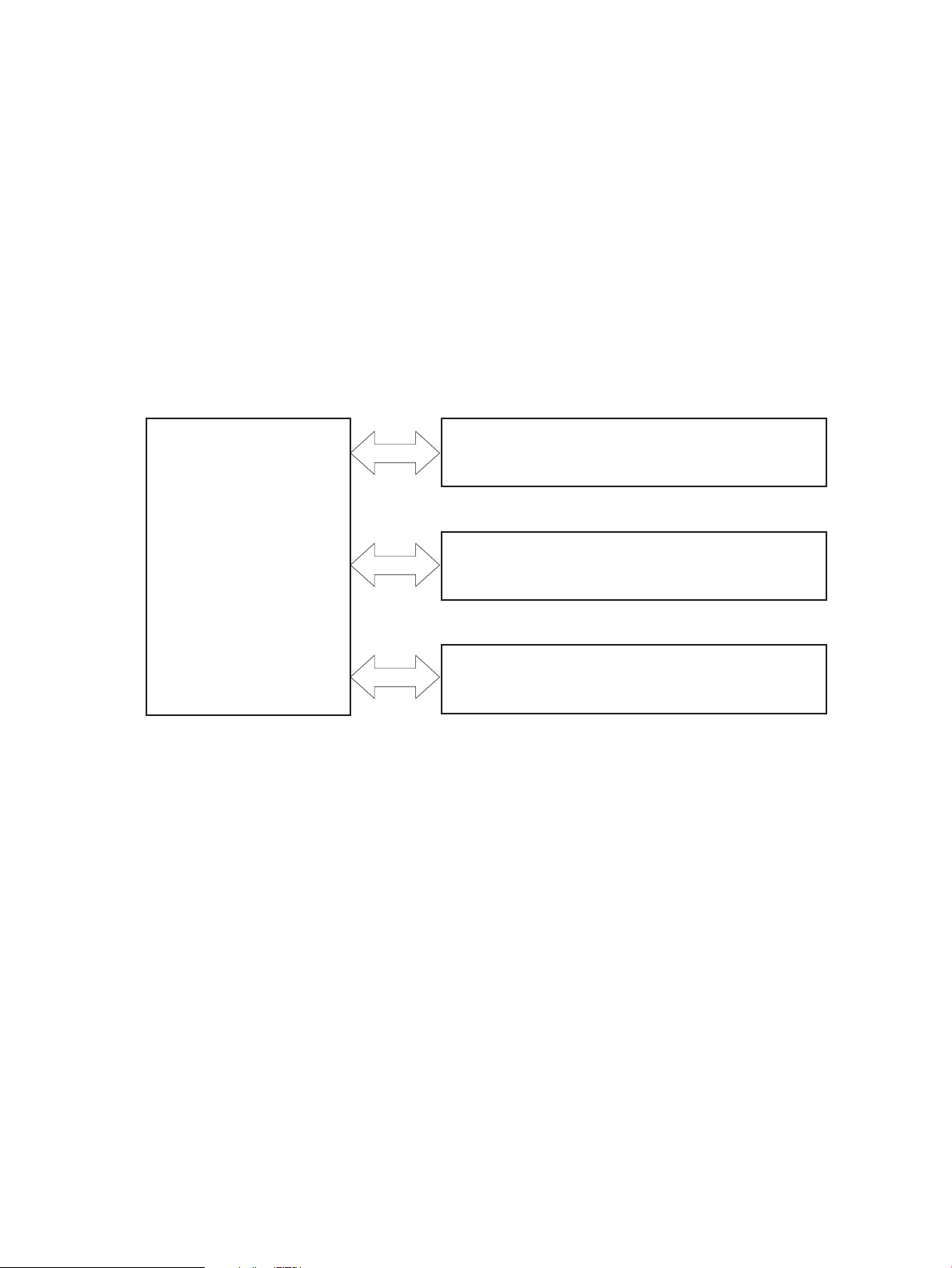
Basic operation
PICKUP-AND-FEED SYSTEM
LASER/SCANNER SYSTEM
ENGINE CONTROL
SYSTEM
IMAGE-FORMATION SYSTEM
Major product systems
The product contains the following major systems:
●
Engine-control system
●
Laser/scanner system
●
Image-formation system
●
Pickup-and-feed system
Product block diagram
Figure 1-1 Product block diagram
2 Chapter 1 Theory of operation ENWW

Sequence of operation
The DC controller in the engine-control system controls the operational sequences of the product. The table
below describes durations and operations for each period of a print operation from when the product is
turned on until the motor stops rotating.
Normal sequence of operation
Table 1-1 Sequence of operation
Name Timing Purpose
WAIT From the time the power switch is turned on, the door is
closed or the product exits Sleep mode until the product
gets ready for a print operation.
STBY (standby) From the end of the WAIT or LSTR period until either a
print command is sent or the power switch is turned off.
INTR (initial
rotation)
PRINT From the end of the INTR period until the last sheet
LSTR (last
rotation)
From the time a print command is received until the
paper is picked up.
completes the fuser operation.
From the end of the PRINT period until the main motor
stops rotating.
Brings the product to ready state. The product
performs the following during the operations:
●
Detects the print cartridge
●
Heats the fuser film in the fuser
●
Rotates, and the stops, the main motor
Maintains the product in printable condition. The
product performs the following during the operation:
●
Enters Auto-Off mode if Auto-Off command is
received
The product performs the following during the
operations:
●
Drives the main motor
●
Activates the high-voltage power supply
●
Activates the laser/scanner
●
Warms the fuser heater
Forms the image on the photosensitive drum based on
the VIDEO signals from the formatter. Transfers and
fuses the toner image to the paper.
Moves the last printed sheet out of the product. The
product performs the following during the operations:
●
Stops the main motor
●
Deactivates the high-voltage power supply
●
Deactivates the laser/scanner
●
Deactivates the fuser heater
The product enters the INTR period as the LSTR period
is completed, if the formatter sends another print
command.
ENWW Basic operation 3

Formatter-control system
The formatter is responsible for the following procedures:
●
Controlling sleep mode
●
Receiving and processing print data from the various product interfaces
●
Monitoring control-panel functions and relaying product-status information (through the control panel
and the network or bidirectional interface)
●
Developing and coordinating data placement and timing with the DC controller PCA
●
Storing font information
●
Communicating with the host computer through the network or the bidirectional interface
The formatter receives a print job from the network or bidirectional interface and separates it into image
information and instructions that control the printing process. The DC controller PCA synchronizes the imageformation system with the paper-input and -output systems, and then signals the formatter to send the
print-image data.
Sleep mode
NOTE: This product uses an Auto-Off feature for sleep mode.
After a user-specified time, the Auto-Off feature automatically conserves electricity by substantially
reducing power consumption when the product is not printing. After a user-specified time, the product
automatically reduces its power consumption (Auto-Off). The product returns to the ready state when a
button is pressed, a print job is received, or a door is opened. When the product is in Auto-Off mode, all of the
control-panel LEDs and the power button backlight LED are off.
NOTE: Although the product lights are off in Auto-Off mode, the product functions normally when it
receives a print job.
Input/output
The product receives print data primarily from the following:
●
Hi-Speed USB 2.0 port
●
802.11b/g/n wireless networking (wireless models only)
CPU
The formatter incorporates a 750 MHz ARM processor.
Memory
The random access memory (RAM) on the formatter PCA contains the page, I/O buffers, and the font storage
area. RAM stores printing and font information received from the host system, and can also serve to
temporarily store a full page of print-image data before the data is sent to the print engine.
Firmware
●
HP LaserJet Pro MFP M225/M226 Printer series
4 Chapter 1 Theory of operation ENWW

◦
●
HP LaserJet Pro M201/M202 Printer series
◦
Memory use
●
HP LaserJet Pro MFP M225/M226 Printer series
◦
●
HP LaserJet Pro M201/M202 Printer series
◦
PJL overview
The printer job language (PJL) is an integral part of configuration, in addition to the standard printer
command language (PCL). With standard cabling, the product can use PJL to perform a variety of functions
such as these:
The product has 256 MB of Synchronous DRAM, which is used for run-time firmware imaging and
specific print job information for the print job.
The product has 128 MB of Synchronous DRAM, which is used for run-time firmware imaging and
specific print job information for the print job.
The product has a 2 KB EEPROM and 256 MB of NAND Flash Memory, which is used for product
configuration information and printer driver firmware.
The product has a 8 KB EEPROM and 64 MB of NAND Flash Memory, which is used for product
configuration information and printer driver firmware.
●
Two-way communication with the host computer through a network connection or a USB connection.
The product can inform the host about such things as the control-panel settings, and the control-panel
settings can be changed from the host.
●
Dynamic I/O switching. The product uses this switching to be configured with a host on each I/O. The
product can receive data from more than one I/O simultaneously, until the I/O buffer is full. This can
occur even when the product is offline.
●
Context-sensitive switching. The product can automatically recognize the personality (PS or PCL) of
each job and configure itself to serve that personality.
●
Isolation of print environment settings from one print job to the next. For example, if a print job is sent
to the product in landscape mode, the subsequent print jobs print in landscape mode only if they are
formatted for landscape printing.
PML
The printer management language (PML) allows remote configuration and status monitoring through the I/O
ports.
LEDM overview
NOTE: HP LaserJet Pro M201/M202 Printer series
The low-end data model (LEDM) provides one consistent data representation method and defines the
dynamic and capabilities tickets shared between clients and devices, as well as the access protocol, event,
security, and discovery methods.
ENWW Formatter-control system 5

ACL overview
The advanced control language (ACL) is a language that supports product control and firmware downloads in
printers that support both PJL/PCL and host-based printing. Each sequence of ACL commands must be
preceded by a unified exit command (UEL) and an @PJL ENTER LANGUAGE=ACL command. The ACL sequence
is always followed by a UEL. Any number of commands can be placed between the UELs. The only exception
to these rules is the download command. If a firmware download is done, the download command must be
the last command in the sequence. It will not be followed by a UEL.
The firmware searches for the UEL sequence when parsing commands. However, while downloading binary
data such as host-based code or NVRAM data the firmware suspends UEL parsing. To handle hosts that
“disappear” during binary sequences, the firmware times out all ACL command sessions. If a timeout occurs
during a non-download command sequence, it is treated as the receipt of a UEL. If a timeout occurs during
firmware download the product resets.
Control panel
The formatter sends and receives product status and command data to and from the control-panel PCA.
USB flash drive
This product features printing from a USB flash drive. This product supports printing the following types of
files from the USB flash drive.
●
PDF
●
RGB JPEG
When a USB flash drive is inserted into the front of the product, the control panel will display the USB Flash
Drive menu. The files present on the USB flash drive can be accessed from the control panel using the touch
screen. Any RGB jpeg or pdf files on the USB flash drive can be printed directly from the product control
panel. Pages also can be scanned and saved to the USB flash drive from the control panel.
6 Chapter 1 Theory of operation ENWW
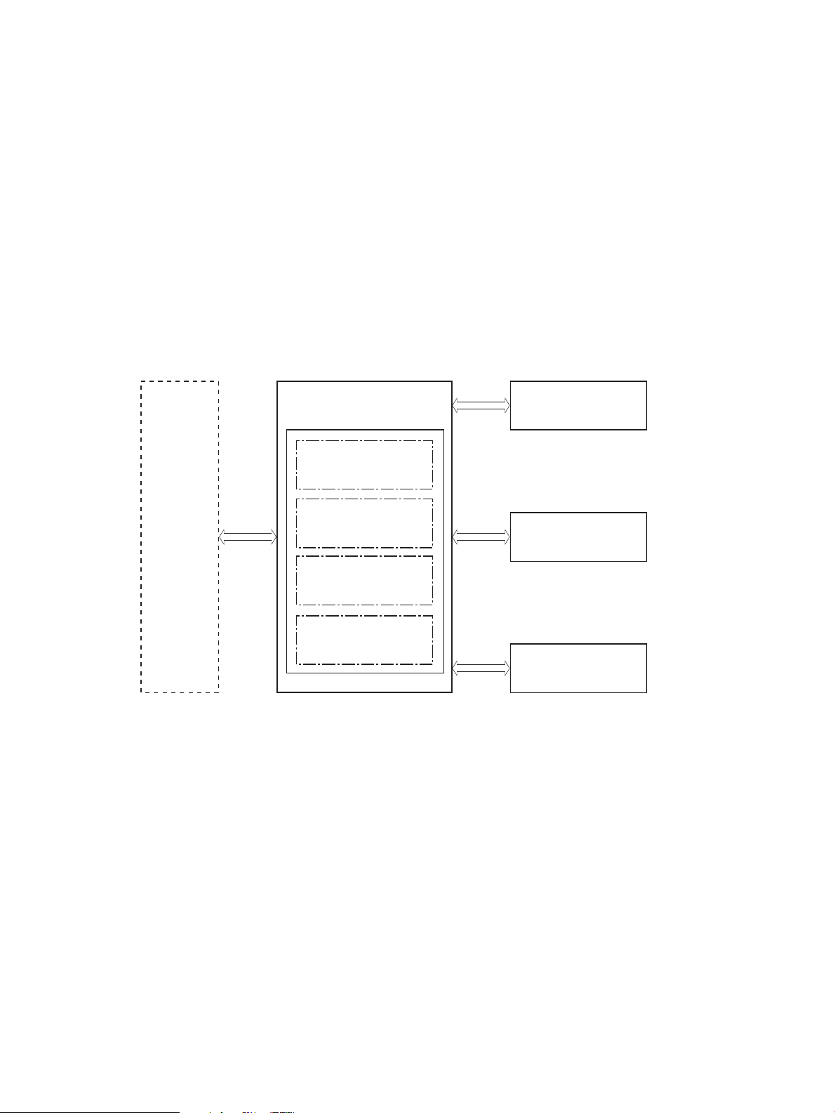
Engine-control system
Formatter
Engine-control system
DC controller
Low-voltage power supply
Laser scanner system
Image-formation system
Pickup, feed and delivery
system
High-voltage power supply
Fuser control
Engine controller
The engine-control system coordinates all product functions, according to commands that the formatter
sends. The engine-control system drives the laser/scanner system, the image-formation system, and the
pickup/feed/delivery system.
The engine control system contains the following major components:
●
Engine-control unit (ECU)
◦
DC controller
◦
Low-voltage power supply
●
High-voltage power supply
●
Fuser control
Figure 1-2 Engine-control system
ENWW Engine-control system 7
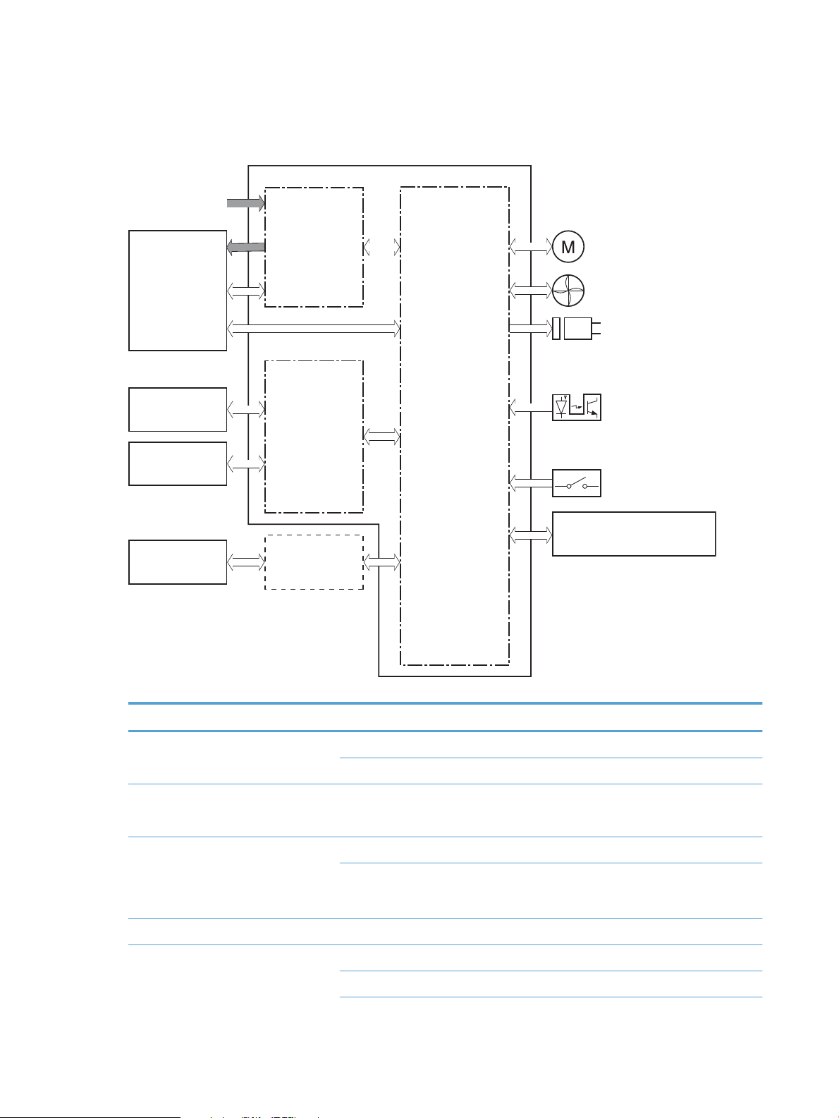
DC controller operations
Fuser
Transfer roller
Cartridge
Control panel
High-voltage
power supply
DC controller
Engine controller
Low-voltage
power supply
Motor
Fan
Solenoid
Photointerrupter
Switch
Laser scanner ass’y
Formatter
AC input
The DC controller controls the operational sequences of the product systems.
Figure 1-3 DC controller block diagram
Table 1-2 DC controller controlled components
Component Designator Description
Motor M1 Main motor
M2 Scanner motor
Fan FM1 Main fan
Solenoid SL1 Pickup solenoid
Switch SW501 Cartridge-door switch
Photointerrupter PS701 Fuser delivery sensor
SL2 Duplex reverse solenoid
PS702 Media-width sensor
Duplex models only.
NOTE: Duplex models only.
8 Chapter 1 Theory of operation ENWW

Table 1-2 DC controller controlled components (continued)
Component Designator Description
PS751 Top-of-Page (TOP) sensor
PS901 Main-motor rotation-number detection sensor
ENWW Engine-control system 9
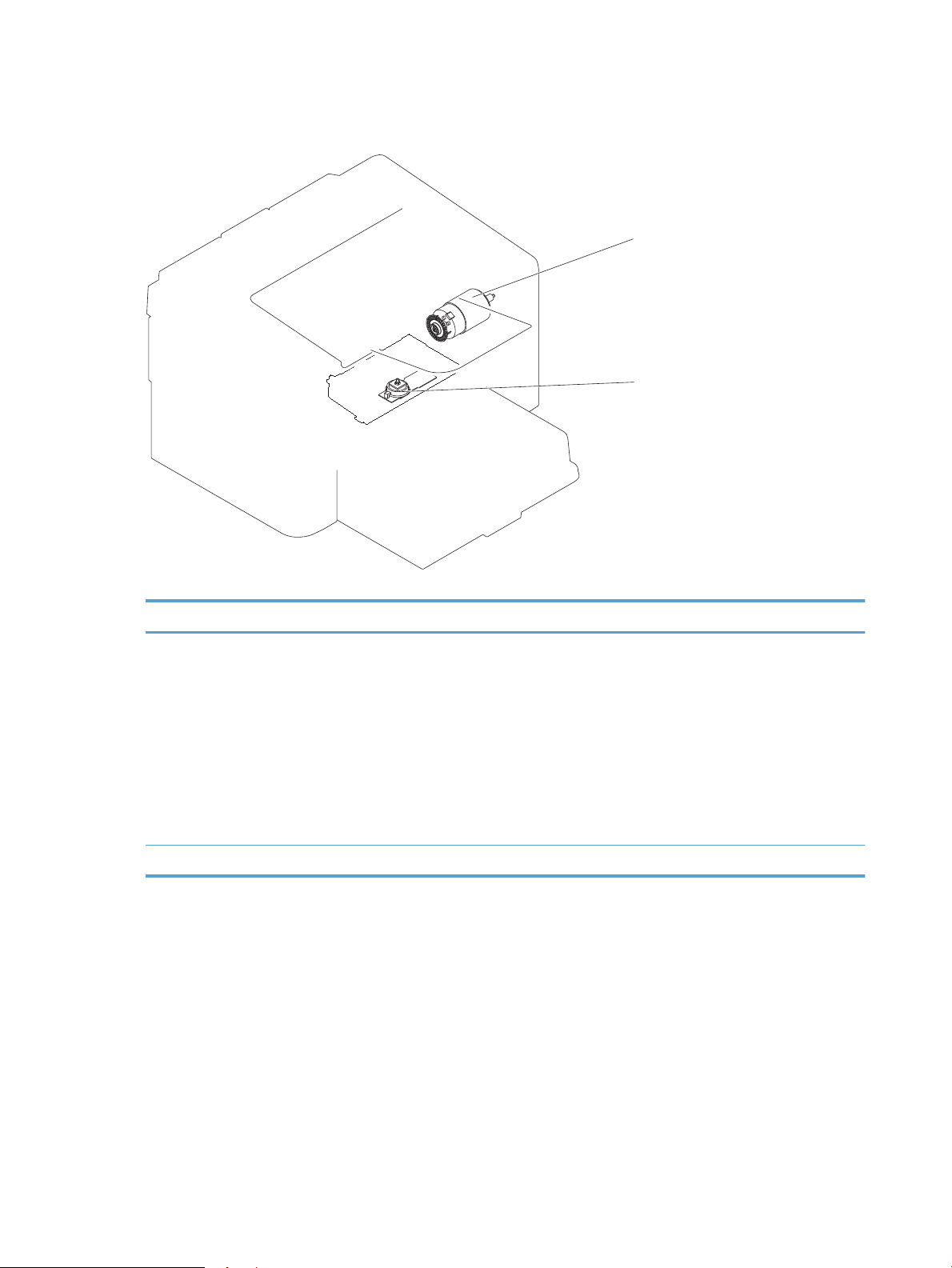
Motors, fans, clutches, solenoids, switches, and sensors
M1
M2
Figure 1-4 Motors
Table 1-3 Motors
Item Description Components driven
M1 Main motor
M2 Scanner motor
●
Pickup roller
●
Feed roller
●
Photosensitive drum
●
Developing roller
●
Pressure roller
●
Delivery roller
●
Duplex feed roller
●
Scanner mirror
10 Chapter 1 Theory of operation ENWW

Figure 1-5 Fans
FM1
Table 1-4 Fans
Item Description
FM1 Main fan
ENWW Engine-control system 11

Figure 1-6 Solenoids and clutches
SL1
SL2
Table 1-5 Solenoids and clutches
Item Description
SL1 Pickup solenoid
SL2 Duplex reverse solenoid
NOTE: Duplex models only.
12 Chapter 1 Theory of operation ENWW

Figure 1-7 Switches
PS751
PS701
PS702
Table 1-6 Switches
Item Description
SW501 Cartridge-door switch
SW502 Power switch; not shown
Figure 1-8 Sensors
Table
1-7 Sensors
Item Description
PS701 Fuser delivery sensor
ENWW Engine-control system 13
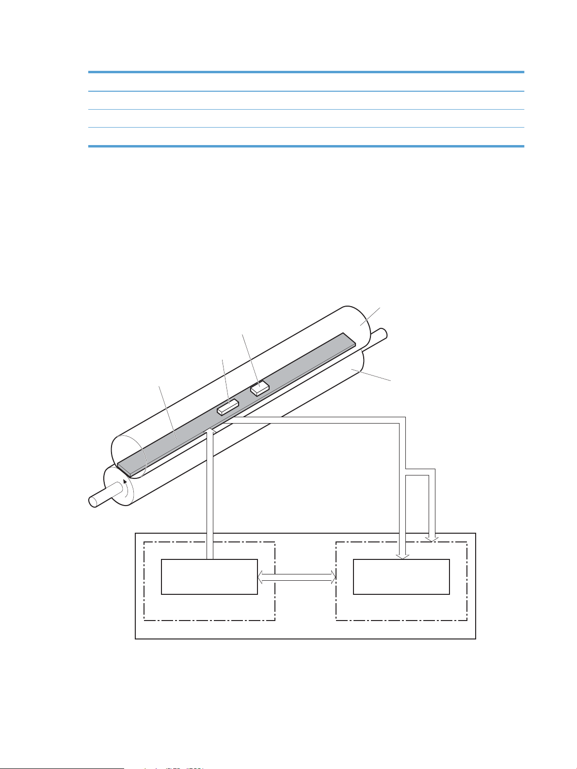
Table 1-7 Sensors (continued)
Fuser heater safety
circuit
H1
FU1
TH1
Fuser film
Pressure roller
FUSER TEMPERATURE signal
Fuser control
FUSER HEATER CONTROL signal
DC controller
Engine controller
Fuser heater control
circuit
Item Description
PS702 Media-width sensor
PS751 Top-of-Page (TOP) sensor
PS901 Main-motor rotation-number sensor; not shown
Fuser-control circuit
The fuser-control circuit monitors and controls the temperature in the fuser. The product uses on-demand
fusing. The fuser-control circuit consists of the following major components:
●
Fuser heater (H1); heats the center area of the fusing film
●
Thermal fuse (FU1): Prevents an abnormal temperature rise of fuser heater (Contact type)
●
Thermistor (TH1); detects the center temperature of the fuser heater (contact type)
Figure 1-9 Fuser control circuit
14 Chapter 1 Theory of operation ENWW

Fuser failure detection
The DC controller determines a fuser unit failure, releases the relay to interrupt power supply to the fuser
heater, and notifies the formatter of a failure state when it encounters the following conditions:
●
Start up failure
◦
If the main thermistor does not detect a specified temperature during the start up process of the
heater in the wait period.
◦
If the main thermistor does not detect a specified temperature during the heater temperature
control in the initial rotation period.
●
Abnormal low temperature
◦
If the main thermistor detects an abnormal low temperature of the fuser unit during the printing
operation.
●
Abnormal high temperature
◦
If the main thermistor detects an abnormal high temperature of the fuser unit.
●
Frequency detection circuit failure
◦
If a specified frequency of the FREQUENCY signal is not detected within a specified period after the
product is turned on.
ENWW Engine-control system 15
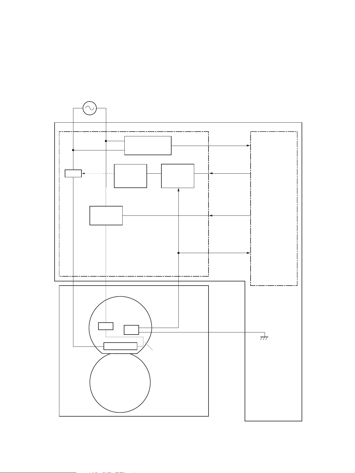
Fuser temperature control
AC power supply
Engine controller
DC controller
Fuser control
Fuser
Pressure roller
Fuser film ass’y
FREQSNS
FSRTH
FSRD
Frequency detection
circuit
(220-240V only)
Fuser heater
control circuit
Fuser heater
safety circuit
Relay control
circuit
RL101
H1
FU1
TH1
RLYD
The fuser temperature control maintains the temperature of the fuser heater at its targeted temperature.
The DC controller monitors the FIXING TEMPERATURE (FSRTH) signals and sends the FIXING HEATER CONTROL
(FSRD) signal according to the detected temperature. The fuser heater control circuit controls the fuser
heater depending on the signal so that the heater remains at the targeted temperature.
Figure 1-10 Fuser-heater control circuit
16 Chapter 1 Theory of operation ENWW

Fuser heater protective function
The fuser heater protective function detects an excessive temperature rise of the fuser unit and interrupts
power supply to the fuser heater.
The following three protective components prevent an abnormal temperature rise of the fuser heater:
●
DC controller
◦
The DC controller monitors the detected temperature of the thermistor. The DC controller
deactivates the FUSER HEATER CONTROL signal and releases the relay (RL101) to interrupt power
supply to the fuser heater when it detects an excessive temperature.
●
Fuser heater safety circuit
◦
The fuser heater safety circuit monitors the detected temperature of the thermistor. The fuser
heater safety circuit releases the relay (RL101) to interrupt power supply to the fuser heater when
it detects an excessive temperature.
●
Thermal fuse
◦
The thermal fuse blows to interrupt power supply to the fuser heater when the temperature of the
fuser heater is abnormally high.
Pressure roller cleaning
The pressure roller cleaning process is initiated by the formatter. The process removes toner that has
accumulated on the pressure roller by transferring it to a sheet of paper.
●
The product feeds a sheet of paper after receiving the cleaning command from the formatter.
●
Main motor rotation is stopped when the trailing edge of the paper passes through the transfer roller.
●
The main motor rotation is repeatedly started and then stopped. The fuser heater is turned on and then
off at the same interval as main motor rotation.
●
Toner adhered to the pressure roller is fused to the paper.
●
The paper is ejected from the product.
ENWW Engine-control system 17

Low-voltage power supply
AC power supply
Low-voltage power supply DC controller
Engine controller
Power supply fuse
FU101
Interlock switch
SW501
Rectifying
circuit
Protection
circuit
Frequency detection
circuit
(220-240V only)
+3.3V
generation
circuit
+24V
generation
circuit
+5V
generation
circuit
Fuser
FREQSNS
+3.3V
+24U
+24V
+24P
+5R
+3.3F
+3.3FON
+3.3UON
+3.3U
BSTSIG
Formatter
+3.3V output
switch circuit
+24V output
switch circuit
High-voltage
power supply
/LVM
The low-voltage power supply (LVPS) converts ac input voltage to dc voltage. The LVPS has two fuses on the
PCA. The LVPS 24 V output is interrupted to the fuser and the high-voltage power supply if the cartridge-door
interlock switch (SW501) is in the off position (cover open).
WARNING! The product power switch only interrupts dc voltage from the LVPS. The ac voltage is present in
the product when the power cord is plugged into a power receptacle and the power switch is in the off
position. You must unplug the product power cord before servicing the product.
Figure 1-11 Low-voltage power supply (LVPS)
18 Chapter 1 Theory of operation ENWW

Table 1-8 List of DC power supply
Main DC voltage Sub-voltage Behavior
+24V +24V
+24P
+24U
+5V +5R
+3.3V +3.3V
+3.3P
+3.3U
●
Constantly supplied
●
Supplied when the power switch is
turned ON
●
Stopped during standby period or
sleep mode
●
Interrupted when the cartridge door
open (SW501)
●
Supplied when the power switch is
turned ON
●
Stopped during standby period or
sleep mode
●
Constantly supplied
●
Supplied when the power switch is
turned ON
●
Stopped during standby period or
sleep mode
●
Supplied when the power switch is
turned ON
ENWW Engine-control system 19

Overcurrent/overvoltage protection
The low-voltage power supply automatically stops supplying the DC voltage to the printer components
whenever it detects excessive current or abnormal voltage.
The low-voltage power supply has a protective function against overcurrent and overvoltage to prevent
failures in the power supply circuit. If an overcurrent or overvoltage condition occurs, the system
automatically cuts off the output voltage.
If DC voltage is not being supplied from the low-voltage power supply, the protective function might be
running. In this case, turn the printer OFF, unplug the power cord. Do not turn the power switch ON until the
root cause is found and corrected.
WARNING! If you believe the overcurrent or overvoltage protection circuits have been activated, do not
plug in the product power cord or turn on the product power until the cause of the failure is found and
corrected.
In addition, the low-voltage power supply has one power supply fuse (FU101) to protect against overcurrent.
If overcurrent flows into the AC line, the fuse blows to stop AC power.
20 Chapter 1 Theory of operation ENWW

High-voltage power supply
Primary
charging bias
circuit
Developing
bias circuit
Transfer bias
circuit
Engine controller
To primary charging roller
To developing roller
Photosensitive drum
Transfer roller
High-voltage power supply
DC controller
Cartridge
The high-voltage power supply (HVPS) applies biases to the following components:
●
Primary charging roller
●
Developing roller
●
Transfer roller
Figure 1-12 High-voltage power supply
ENWW Engine-control system 21
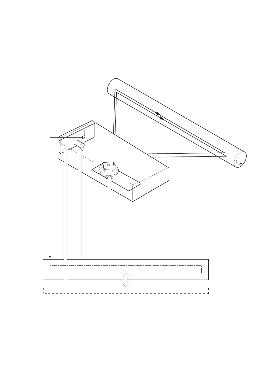
Laser/scanner system
Formatter
DC controlle r
BDI signal
VIDEO signal
LASER CONTROL signal
SCANNER MOTOR CONTROL signal
Engine controller
Photosensitive drum
Scanning mirror
BD sensor
Laser unit
Scanner motor unit
The laser/scanner system receives VIDEO signals from the ECU and formatter and converts the signals into
latent images on the photosensitive drum.
The main components of the laser/scanner are the laser unit and the scanner motor unit. The DC controller
sends signals to the laser/scanner to control the functions of these components.
Figure 1-13 Laser/scanner system
Laser failure detection
The DC controller determines an optical unit failure and notifies the formatter, if the laser/scanner
encounters the following conditions:
22 Chapter 1 Theory of operation ENWW

●
The scanner motor does not reach a specified rotation within a specified period of the scanner motor
start up.
●
The rotation of the scanner motor is out of specified range for a specified period during the scanner
motor drive.
●
The BD interval is out of a specified value during a print operation.
ENWW Laser/scanner system 23

Image-formation system
High-voltage power supply
DC controller
Engine controller
Laser scanner
Cartridge
Transfer roller
Electrophotographic process
The electrophotographic process forms an image on the paper. Following are the major components used in
the process:
●
Print cartridge
●
Transfer roller
●
Fuser
●
Laser/scanner
●
High-voltage power supply
The DC controller uses the laser/scanner and HVPS to form the toner image on the photosensitive drum. The
image is transferred to the paper and then fused onto the paper.
Figure 1-14 Electrophotographic process block diagram (1 of 2)
The DC controller rotates the main motor to drive the following components:
●
Photosensitive drum
●
Developing drum
●
Primary charging roller (follows the rotation of the photosensitive drum)
●
Transfer roller (follows the rotation of the photosensitive drum)
24 Chapter 1 Theory of operation ENWW

Figure 1-15 Electrophotographic process block diagram (2 of 2)
DC controller
Engine controller
Cartridge
Transfer roller
Developing roller
Main motor
Photosensitive drum
Primary charging roller
ENWW Image-formation system 25

Image formation process
Each of the following process function independently and must be coordinated with the other product
processes. Image formation consists of the following processes:
●
Latent-image formation block
◦
Step 1: primary charging
◦
Step 2: laser-beam exposure
●
Developing block
◦
Step 3: developing
●
Transfer block
◦
Step 4: transfer
◦
Step 5: separation
●
Fusing block
◦
Step 6: fusing
●
Drum cleaning block
◦
Step 7: drum cleaning
Figure 1-16 Image formation process
26 Chapter 1 Theory of operation ENWW

Latent-image formation stage
DC bias
Photosensitive drum
Primary charging roller
Laser beam
Unexposed area Exposed area
During the latent-image formation stage, the laser/scanner forms an invisible image on the photosensitive
drum in the print cartridge.
Primary charging
Step 1: DC and AC biases are applied to the primary charging roller, which transfers a uniform negative
potential to the photosensitive drum.
Figure 1-17 Primary charging
Laser beam exposure
Step 2: The laser beam scans the photosensitive drum to neutralize negative charges on parts of the drum
surface. An electrostatic latent image is formed on the drum where negative charges were neutralized.
Figure 1-18 Laser beam exposure
ENWW Image-formation system 27
Developing stage
Blade
Developing cylinder
AC bias
DC bias
Photosensitive drum
Unexposed area
Exposed area
Exposed area
Unexposed area
Print cartridge
Step 3: In the print cartridge, the developing cylinder transfers toner onto the electrostatic latent image on
the photosensitive drum.
Figure 1-19 Print cartridge
Toner acquires a negative charge from the friction that occurs when the developing roller rotates against the
developing blade. The developing bias is applied to the developing roller to make a potential difference
between the developing roller and the photosensitive drum. The negatively charged toner is attracted to the
latent image on the photosensitive drum because the drum surface has a higher potential.
28 Chapter 1 Theory of operation ENWW

Transfer stage
Media
Transfer roller
Photosensitive
drum
DC bias
Media
Transfer roller
Photosensitive
drum
Static charge eliminator
Step 4: The transfer charging roller, to which a DC positive bias is applied, imparts a positive charge on the
paper. When the page comes in contact with the photosensitive drum, the toner is transferred to the paper.
Figure 1-20 Transfer
Step 5: The elasticity of the paper causes its separation from the photosensitive drum. A static charge
eliminator aids separation by weakening any electrostatic adhesion.
Figure 1-21 Separation
Fusing stage
ENWW Image-formation system 29
Step 6: The DC negative bias applied to the fusing film strengthens the holding force of the toner on the
paper and prevents the toner from scattering.
The product uses an on-demand fuser method. The toner image is permanently affixed to the paper by heat
and pressure.

Figure 1-22 Fusing
Fuser film
Toner
Pressure roller
Fuser heater
Media
Waste toner container
Photosensitive
drum
Cleaning blade
Cleaning stage
Step 7: The cleaning blade scrapes the residual toner off of the photosensitive drum and deposits it into the
waste toner case.
Figure 1-23 Drum cleaning
30 Chapter 1 Theory of operation ENWW

Pickup, feed, and delivery system
Duplex media path
Simplex media path
Pickup roller
Feed roller
Duplex
feed roller
Single-sheet-feed slot
Separation pad
Photosensitive drum
Transfer roller
Fuserfilm
Pressure roller
Delivery roller
Duplex feed unit
The media feed system picks up, feeds, and delivers the page.
Figure 1-24 Pickup, feed, and delivery system block diagram
ENWW Pickup, feed, and delivery system 31

Photo sensors and switches
M1
PS751
PS701
PS702
SL2
SL1
NOTE: The illustration in this section also shows the product motor, photo sensors, and solenoid. The
power switch is not shown.
Figure 1-25 Photo sensors, motor, and solenoid
Table 1-9 Photo sensors, motor, and solenoid
Item Description
M1 Main motor
SL1 Pickup solenoid
32 Chapter 1 Theory of operation ENWW

Table 1-9 Photo sensors, motor, and solenoid (continued)
Item Description
SL2 Duplex feed solenoid
NOTE: Duplex models only.
PS701 Fuser delivery sensor
PS702 Media-width sensor
PS751 TOP sensor
ENWW Pickup, feed, and delivery system 33
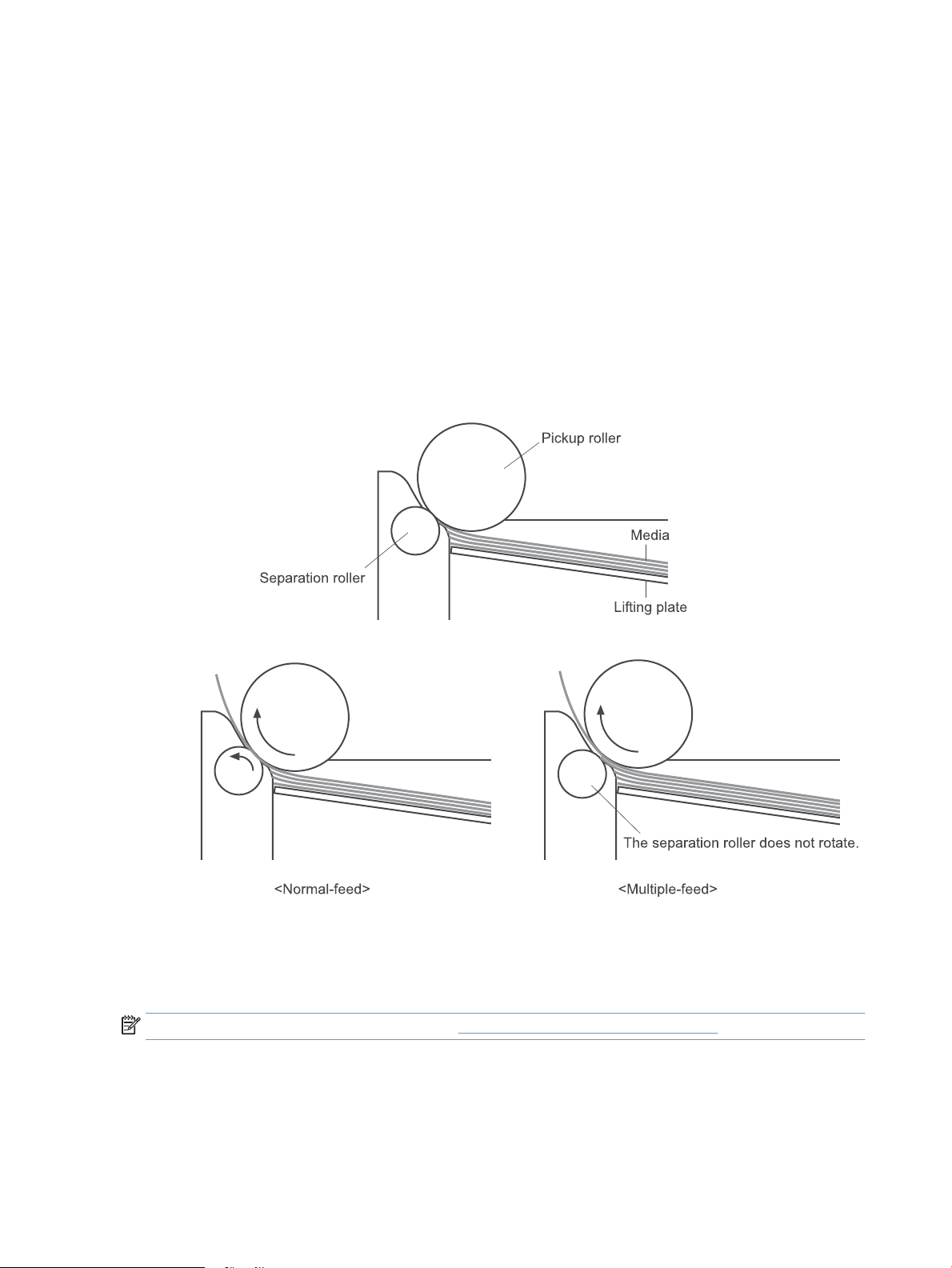
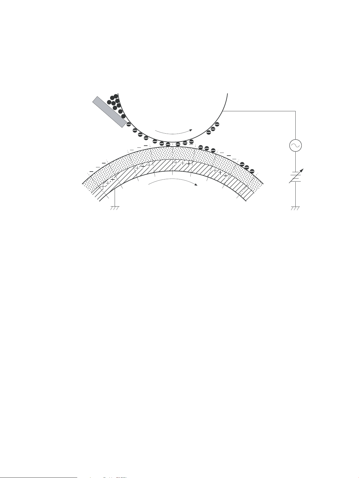
Multiple-feed prevention
The product uses a separation roller to prevent multiple sheets of media from entering the product. The
paper separation roller follows the rotational direction of the pickup roller because it does not have its own
driving force.
●
Normal-feed: The separation roller is driven by the pickup roller through a sheet of print media. That is,
the separation roller rotates in the media feed direction.
●
Multiple-feed: The low friction force between the sheets weakens the rotational force from the pickup
roller. The separation roller is limited in its rotational force and it does not rotate with such a weak
driving force from the pickup roller. Since the separation roller does not rotate, the multiple sheets do
not feed into the product.
The following figure illustrates the mechanism of the multiple-feed prevention.
Figure 1-26 Multiple-feed prevention
Jam detection
The product uses the following sensors to detect the presence of paper and to check for jams. The page must
pass each sensor within a specified time.
NOTE: To find the following components, see Photo sensors and switches on page 32.
●
PS701; fuser delivery sensor
●
PS702; TOP sensor
34 Chapter 1 Theory of operation ENWW

NOTE: The product automatically ejects paper if the TOP sensor detects residual paper within the
product when the power is turned on or the door is closed.
The product detects the following jams:
●
Pickup stationary jam
●
Delivery delay jam
●
Delivery stationary jam
●
Fuser wrapping jam
●
Door open jam
●
Residual media jam
●
Duplex reverse delay jam (duplex models only)
●
Duplex reverse stationary jam (duplex models only)
●
Duplex re-pickup delay jam (duplex models only)
ENWW Pickup, feed, and delivery system 35

Scanning and image capture system
The flatbed image scanner captures an electronic image of the document on the glass. The scanner does this
by illuminating the document with LEDs (red, green, and blue) and capturing the image in the image sensor to
create an electronic format of the document. The flatbed scanner consists of three main elements.
●
CIS scanner
The CIS (contact image sensor) scanner captures an image using the product's optical path. Red, green,
and blue LEDs sequentially illuminate a small strip of the document (often called a raster line), and the
optical system captures each color in a single row of CCD sensors that cover the entire page width.
Because only one color is captured for each line per exposure, the three colors are recombined
electronically to create the full color image. For monochromatic scans or copies, all three LEDs are
illuminated to create a white light for the scan so the raster line can be captured in one exposure.
●
Mechanical drive system
The drive system moves the CIS scanner along the document length to create the image. In this product,
the drive system consists of a small DC motor with an optical encoder, which operates a rack and pinion
mechanism to move the CIS scanner. The speed of the drive system is proportional to the scan
resolution (300 ppi is much faster than 1200 ppi) and also proportional to the type of scan (color scans
are slower than monochromatic scans).
The carriage drive moves the CIS scan head along the document length to create the image. In this
product, a small DC motor with an optical encoder creates this motion. The speed of the carriage drive is
proportional to the scan resolution (300 ppi is much faster than 600 ppi) and also proportional to the
type of scan (color scans are three-times slower than monochromatic scans).
●
Image processing system (formatter)
The formatter processes the scanner data into either a copy or a scan to the computer. For copies, the
image data is sent directly to the product without being transmitted to the computer. Depending on
user selections for the copy settings, the formatter enhances the scanner data significantly before
sending it to the product. Image data is captured at 300 ppi for copies and is user selectable for scans to
the computer. Each pixel is represented by 8 bits for each of the three colors (256 levels for each color),
for a total of 24 bits per pixel (24-bit color).
Scanner power-on sequence of events
When the product is turned on, it performs the following tests:
●
Motor test. The product moves the motor left and right to confirm operation. It reports a scanner error
12 if no motion is detected in the motor encoder system.
●
Wall find. The scan carriage moves slowly to the left while watching an encoder on the carriage motor
to determine when the carriage has found the side wall or stop. This enables the product to identify the
document origin (position of the original). If the document origin cannot be located, a default position is
used instead.
●
LED check. The product moves the carriage to the white calibration label under the left side of the
flatbed image scanner, and it verifies that the minimum and maximum response is acceptable. It
reports a scanner error 14 if the response is unacceptable.
●
Home find. The scan carriage uses the optical scanner to find physical reference features that relate to
the document origin at the left side of the image glass. This process ensures accurate location of the
36 Chapter 1 Theory of operation ENWW

first document pixels so that the user documents will have an accurate placement of the image on
scans and copies. It reports a scanner error 6 message if the reference features are not found.
●
Calibration. This test, also known as scanner color calibration, enables the product to identify the black
and white on every pixel in the CCD. Calibration occurs in two major processes: a broad (analog)
adjustment of all pixels to bring them into the target output range, and a pixel-by-pixel adjustment
(digital) to fine tune the actual black and white response. The calibration process occurs under the left
side of flatbed image scanner where there is a special white calibration label.
Calibration is the most important step in creating a high quality image. Calibration problems can include
color inaccuracies, brightness inaccuracies, and vertical streaks through the image. The calibration
process identifies any bad pixels and enables the image formatter to recreate the lost information from
adjacent pixels. Extreme cases of this problem can appear as large vertical streaks or image smears.
The user has no control over the calibration process itself or this pixel-replacement process.
Copy or scan sequence of events
To create an accurate rendition of a document, the scanner must be calibrated for the requested operation. If
the user selects a scan at 600 ppi color, the flatbed image scanner calibrates for that specific operational
mode. Subsequently, the flatbed image scanner automatically re-calibrates for the next requested
operation. Calibration does not occur for every new copy request.
Normal sequence of operation for a flatbed copy or scan job includes the following.
1. LEDs illuminate.
2. Carriage motion begins moving the CIS scanner toward the right.
3. Image capture continues for the entire page or length requested in a scan operation.
4. Carriage returns to the home position on the left.
ENWW Scanning and image capture system 37

Scanner operation
1 2 3 4
Figure 1-27 Scanner mechanism
Callout Description
1 FFC
2 Calibration strip
3 Rack
4 Carriage
At power-on, the CIS scanner moves slowly to the left. The motor encoder is monitored to determine when
the scanner has found the left side wall. The scanner then moves to the right and identifies the document
origin (position of the original). If the document origin cannot be located, a default position is used.
When a copy/scan is initiated, the product first checks to determine if a document is present in the ADF. If an
ADF document is detected, the scanner moves to the left side of the scan tub and scans the image as the
document is fed through the ADF.
If no document is detected in the ADF, the scanner acquires the image from the flatbed by scanning while
moving from left to right across the flatbed glass.
38 Chapter 1 Theory of operation ENWW

ADF operation
The ADF will not function when the ADF cover is open. The paper path is incomplete if the ADF cover is lifted
from the glass.
The standard operation of the ADF consists of the standby (paper loading) mode, pick, feed, and lift steps:
●
Standby (paper-loading) mode
In standby mode, the lift plate is in the down position. When a document is loaded into the input tray,
the paper-present sensor detects its presence.
When a copy/scan is initiated, the ADF motor engages the gear train and raises the lift plate until the
document makes contact with the pick roller. The ADF then begins the pick, feed, and lower sequence:
●
Pick
The pick roller rotates and moves one or more sheets forward into the ADF where the sheets engage
with the separation roller. The separation roller contacts the ADF separation pad, which separates
multiple sheets into a single sheet.
●
Feed
The single sheet continues through the ADF paper path (aided by the pre-scan rollers) until the leading
edge of the page activates the top-of-form sensor. Activation of this sensor initiates the scan process,
and the scanner acquires the image as the document moves over the ADF glass. The post-scan rollers
then eject the sheet into the output area. The pick and feed steps are repeated as long as paper is
detected by the paper-present sensor.
●
Home
When the form sensor detects the trailing edge of the last page, the last sheet is ejected and the motor
turns on a sequence that rests the separation floor back down in standby mode, which allows it to
detect when more media is loaded.
Note that the ADF will not function when the ADF door is open.
ADF paper path and ADF sensors
The paper-present sensor determines if paper is in the ADF. The form sensor detects the top and bottom
edges of the document.
The following diagram shows the ADF paper path.
ENWW ADF operation 39

Figure 1-28 ADF paper path
1345
67810 9
2
Item Description
1 Separation pad
2 Separation roller
3 Paper present sensor
4 Pre-feed roller
5 Input area
6 Output area
7 Post-scan roller
8 ADF glass
9 Top-of-Form sensor
10 Pre-scan roller
The paper-present sensor determines if paper has been loaded in the ADF. The top-of-form sensor detects
the top and bottom edges of the document.
ADF jam detection
The ADF uses two sensors to determine if a jam has occurred. The paper-present sensor detects the presence
of media in the ADF input tray. The top-of-form sensor detects media moving through the ADF. A jam can be
detected under any of the following conditions:
●
Document feeder mispick
When a document is detected in the ADF input tray and a command to copy/scan is received, the ADF
attempts to pick the page from the input tray. If the page is not picked is not successfully, the ADF will
pulse the motor and cycle the lift plate in an attempt to dislodge the stuck page. Three attempts are
40 Chapter 1 Theory of operation ENWW

made to advance the paper to the form sensor. If the paper does not advance, a Document feeder
mispick message will appear on the control panel display.
●
Long-document jam
If a page is picked and advanced to the top-of-form sensor, but the trailing edge of the page is not
detected within the time allowed for a 381-mm (15-inch) document (the maximum allowable page
length for the ADF), a Document feeder jam message will appear on the control panel display.
●
Stall jam
When a page that is less than 381 mm (15 inches) long has advanced to the top-of-form sensor but has
not left it within the expected period of time, the page has probably stalled or jammed, and a Document
feeder jam message will appear on the control panel display.
When a jam is detected, the ADF stops feeding paper, and displays a jam message on the control-panel
display.
ENWW ADF operation 41

Fax functions and operation
The following sections describe the product fax capabilities.
Computer and network security features
The product can send and receive fax data over telephone lines that conform to public switch telephone
network (PSTN) standards. The secure fax protocols make it impossible for computer viruses to be
transferred from the telephone line to a computer or network.
The following product features prevent virus transmission:
●
No direct connection exists between the fax line and any devices that are connected to the USB or
Ethernet ports.
●
The internal firmware cannot be modified through the fax connection.
●
All fax communications go through the fax subsystem, which does not use Internet data-exchange
protocols.
PSTN operation
The PSTN operates through a central office (CO) that generates a constant voltage on the TIP and RING wires
(48 V, usually). A device goes on-hook by connecting impedance (such as 600 ohms for the U.S.) across the
TIP and RING so that a line current can flow. The CO can detect this current and can send impulses like dial
tones. The product generates more signaling tones, such as dialing digits, to tell the CO how to connect the
call. The product can also detect tones, such as a busy tone from the CO, that tell it how to behave.
When the call is finally connected, the CO behaves like a piece of wire connecting the sender and receiver.
This is the period during which all of the fax signaling and data transfer occurs. When a call is completed, the
circuit opens again and the line-current flow ceases, removing the CO connection from both the sender and
the receiver.
On most phone systems, the TIP and RING wires appear on pins 3 and 4 of the RJ-11 modular jack (the one on
the fax card). These two wires do not have to be polarized because all the equipment works with either TIP or
RING on pin 3 and the other wire on pin 4. This means that cables of either polarity can interconnect and will
still work.
These basic functions of PSTN operation are assumed in the design of the fax subsystem. The product
generates and detects the signaling tones, currents, and data signals that are required to transmit and
receive faxes on the PSTN.
Receive faxes when you hear fax tones
In general, incoming faxes to the product are automatically received. However, if other devices are connected
to the same phone line, the product might not be set to answer automatically.
If the product is connected to a phone line that receives both fax and phone calls, and you hear fax tones
when you answer the extension phone, receive the fax in one of two ways:
●
If you are near the product, press Start Fax on the control panel.
●
Press 1-2-3 in sequence on the extension phone keypad, listen for fax transmission sounds, and then
hang up.
NOTE: In order for the second method to work, the Extension Phone setting must be set to Yes.
42 Chapter 1 Theory of operation ENWW

Distinctive ring function
Ring-pattern or distinctive-ring service is available through some local telephone companies. The service
allows you to have more than one telephone number on a single line. Each telephone number has a unique
ring pattern, so that you can answer voice calls and the product can answer fax calls.
If you subscribe to a ring-pattern service with a telephone company, you must set the product to answer the
correct ring pattern. Not all countries/regions support unique ring patterns. Contact the telephone company
to determine if this service is available in your country/region.
NOTE: If you do not have ring-pattern service and you change the ring-pattern settings to something other
than the default, All Rings, the product might not be able to receive faxes.
The settings are as follows:
●
All Rings: The product answers any calls that come through the telephone line.
●
Single: The product answers any calls that produce a single-ring pattern.
●
Double: The product answers any calls that produce a double-ring pattern.
●
Triple: The product answers any calls that produce a triple-ring pattern.
●
Double and Triple: The product answers any calls that produce a double-ring or triple-ring pattern.
Set up the distinctive ring function
1. From the Home screen, touch the Setup button.
2. Touch the Fax Setup menu.
3. Touch the Basic Setup menu.
4. Touch the Distinctive Ring, and then touch the name of an option.
Fax by using Voice over IP services
Voice over IP (VoIP) services provide normal telephone service, including long distance service through a
broadband Internet connection. These services use packets to break up the voice signal on a telephone line
and transmit it digitally to the receiver, where the packets are reassembled. The VoIP services are often not
compatible with fax machines. The VoIP provider must state the service supports fax over IP services.
Because the installation process varies, the VoIP service provider will have to assist in installing the product
fax component.
Although a fax might work on a VoIP network, it can fail when the following events occur:
●
Internet traffic becomes heavy and packets are lost.
●
Latency (the time it takes for a packet to travel from its point of origin to its point of destination)
becomes excessive.
If you experience problems using the fax feature on a VoIP network, ensure that all of the product cables and
settings are correct. Configuring the Fax Speed setting to Medium(V.17) or Slow(V.29) can also improve your
ability to send a fax over a VoIP network.
If you continue to have problems faxing, contact your VoIP provider.
ENWW Fax functions and operation 43

The fax subsystem
The formatter, fax card, firmware, and software all contribute to the fax functionality. The designs of the
formatter and fax card, along with parameters in the firmware, determine the majority of the regulatory
requirements for telephony on the product.
The fax subsystem is designed to support V.34 fax transmission, lower speeds (such as V.17 fax), and older
fax machines.
Fax card in the fax subsystem
Two versions of the fax card are used in the product. One is used in the North American, South American, and
Asia Pacific countries/regions. The other is used primarily in European countries/regions.
The fax card contains the modem chipset (DSP and CODEC) that controls the basic fax functions of tone
generation and detection, along with channel control for fax transmissions. The CODEC and its associated
circuitry act as the third-generation silicon data access arrangement (DAA) to comply with worldwide
regulatory requirements.
The only difference between the two versions is that each version is compliant with the 2/4-wire phone jack
system from the respective country/region.
Safety isolation
The most important function of the fax card is the safety isolation between the high-voltage, transient-prone
environment of the telephone network (TNV [telephone network voltage]) and the low-voltage analog and
digital circuitry of the formatter (SELV [secondary extra-low voltage]). This safety isolation provides both
customer safety and product reliability in the telecom environment.
Any signals that cross the isolation barrier do so magnetically. The breakdown voltage rating of barriercritical components is greater than 5 kV.
Safety-protection circuitry
In addition to the safety barrier, the fax card protects against over-voltage and over-current events.
Telephone over-voltage events can be either differential mode or common mode. The event can be transient
in nature (a lightning-induced surge or ESD) or continuous (a power line crossed with a phone line). The fax
card protection circuitry provides margin against combinations of over-voltage and over-current events.
Common mode protection is provided by the selection of high-voltage-barrier critical components
(transformer and relay). The safety barrier of the fax card PCB traces and the clearance between the fax card
and surrounding components also contribute to common mode protection.
A voltage suppressor (a crowbar-type SIDACTOR) provides differential protection. This product becomes low
impedance at approximately 300 V differential, and crowbars to a low voltage. A series thermal switch works
in conjunction with the crowbar for continuous telephone line events, such as crossed power lines.
All communications cross the isolation barrier magnetically. The breakdown voltage rating of barrier-critical
components is greater than 5 kV.
Data path
TIP and RING are the two-wire paths for all signals from the telephone network. All signaling and data
information comes across them, including fax tones and fax data.
44 Chapter 1 Theory of operation ENWW

The telephone network uses DC current to determine the hook state of the telephone, so line current must be
present during a call. The silicon DAA provides a DC holding circuit to keep the line current constant during a
fax call.
The silicon DAA converts the analog signal to a digital signal for DSP processing, and also converts the digital
signal to an analog signal for transmitting data through a telephone line.
The magnetically coupled signals that cross the isolation barrier go either through a transformer or a relay.
The DSP in the fax card communicates with the ASIC in the formatter using the high-speed serial interface.
Hook state
Another magnetically coupled signal is the control signal that disconnects the downstream telephone
devices (such as a phone or answering machine). A control signal originating on the DSP can change the relay
state, causing the auxiliary jack (downstream jack) to be disconnected from the telephone circuit.
The product takes control of calls that it recognizes as fax calls. If the product does not directly pick up the
call, it monitors incoming calls for the fax tone or for the user to direct it to receive a fax. This idle mode is
also called eavesdropping. This mode is active when the product is on-hook but current exists in the
downstream phone line because another device is off-hook. During eavesdropping, the receive circuit is
enabled but has a different gain from the current that is generated during normal fax transmissions.
The product does not take control of the line unless it detects a fax tone or the user causes it to connect
manually. This feature allows the user to make voice calls from a phone that is connected to the product
without being cut off if a fax is not being received.
Downstream current detection
The line voltage monitoring module of the silicon DAA can detect the line state as well as the downstream
device. It tells DSP via DIB that an active device (telephone, modem, or answering machine) is connected to
the auxiliary port on the product (the right side of the RJ-11 jack). The DSP uses the signal to ensure that the
product does not go off-hook (and disconnect a downstream call) until it has been authorized to do so (by a
manual fax start or the detection of the appropriate tones).
Hook switch control
In the silicon DAA the CODEC controls the hook switch directly. The CODEC is activated when it receives
commands from the DSP. When the circuit is drawing DC current from the central office it is considered offhook. When no DC current flows the state is considered on-hook.
Ring detect
Ring detect is performed by the line voltage monitoring module of the silicon DAA, and is a combination of
voltage levels and cadence (time on and time off). Both must be present to detect a valid ring. The CODEC
works with DSP as well as the firmware to determine if an incoming signal is an answerable ring.
Line current control
The DC current from the CO needs to have a path to flow from TIP to RING. The DC impedance emulation line
modulator and DC terminations modules in the silicon DAA act as a DC holding circuit, and works with the
firmware to achieve the voltage-current characteristic between TIP and RING. The impedance (the currentvoltage characteristic) changes corresponding to certain special events, such as pulse dialing or when the
product goes on-hook.
ENWW Fax functions and operation 45

Billing- (metering-) tone filters
Switzerland and Germany provide high-frequency AC signals on the phone line in order to bill customers.
A filter in a special fax cable (for certain countries/regions), can filter these signals. Because these billing
signals are not used in the U.S., these filters are not present in the U.S. fax cable.
To obtain a special fax cable, contact your local telephone service provider.
Fax page storage in flash memory
Fax pages are the electronic images of the document page. They can be created in any of three ways:
scanned to be sent to another fax machine, generated to be sent by the computer, or received from a fax
machine to be printed.
The product stores all fax pages in flash memory automatically. After these pages are written into flash
memory, they are stored until the pages are sent to another fax machine, printed on the product, transmitted
to the computer, or erased by the user.
These pages are stored in flash memory, which is the nonvolatile memory that can be repeatedly read from,
written to, and erased. The product has 8 MB of flash memory, of which 7.5 MB is available for fax storage.
The remaining 0.5 MB is used for the file system and reclamation. Adding RAM does not affect the fax page
storage because the product does not use RAM for storing fax pages.
Stored fax pages
The user can reprint stored fax receive pages in case of errors. For a fax send, the product will resend the fax
in case of errors. The product will resend stored fax pages after a busy signal, communication error, no
answer, or power failure. Other fax devices store fax pages in either normal RAM or short-term RAM. Normal
RAM immediately loses its data when power is lost, while short-term RAM loses its data about 60 minutes
after power failure. Flash memory maintains its data for years without any applied power.
Advantages of flash memory storage
Fax pages that are stored in flash memory are persistent. They are not lost as a result of a power failure, no
matter how long the power is off. Users can reprint faxes in case the print cartridge runs out of toner or the
product experiences other errors while printing faxes.
The product also has scan-ahead functionality that makes use of flash memory. Scan-ahead automatically
scans pages into flash memory before a fax job is sent. This allows the sender to pick up the original
document immediately after it is scanned, eliminating the need to wait until the fax is transmission is
complete.
Because fax pages are stored in flash memory rather than RAM, more RAM is available to handle larger and
more complicated copy and print jobs.
46 Chapter 1 Theory of operation ENWW

USB flash drive
This product features printing from a USB flash drive. This product supports printing the following types of
files from the USB flash drive.
●
PDF
●
RGB JPEG
When a USB flash drive is inserted into the front of the product, the control panel will display the USB Flash
Drive menu. The files present on the USB flash drive can be accessed from the control panel using the touch
screen. Any RGB jpeg or pdf files on the USB flash drive can be printed directly from the product control
panel. Pages also can be scanned and saved to the USB flash drive from the control panel.
ENWW USB flash drive 47

48 Chapter 1 Theory of operation ENWW

2 Solve problems
●
Troubleshooting process
●
Tools for troubleshooting
●
Improve print quality, print-only products
●
Improve print quality, MFP products
●
Improve copy and scan quality
●
Improve fax image quality
●
Solve Paper Jam or feed problems
●
Solve performance problems
●
Solve connectivity problems
●
Service mode functions, print-only products
●
Service mode functions, MFP products
●
Solve fax problems
●
Product updates
ENWW 49

Troubleshooting process
Pre-troubleshooting checklist
The following table includes basic questions to ask the customer to quickly help define the problem(s).
General topic Questions
Environment
Media
Input trays
●
Is the product installed on a solid, level surface (+/- 1°)?
●
Is the power-supply voltage within ± 10 volts of the specified power source?
●
Is the power-supply plug inserted in the product and the outlet?
●
Is the operating environment within the specified parameters?
●
Is the product exposed to ammonia gas, such as that produced by diazo copiers or
office cleaning materials?
NOTE: Diazo copiers produce ammonia gas as part of the copying processes.
Ammonia gas (from cleaning supplies or a diazo copier) can have an adverse affect
on some product components (for example, the print-cartridge OPC).
●
Is the product exposed to direct sunlight?
●
Does the customer use only supported media?
●
Is the media in good condition (no curls, folds, or distortion)?
●
Is the media stored correctly and within environmental limits?
●
Is the amount of media in the tray within specifications?
●
Is the media correctly placed in the tray?
●
Are the paper guides aligned with the stack?
●
Is the cassette correctly installed in the product?
Toner cartridges
Transfer unit and fuser
Covers
Condensation
Miscellaneous
●
Is each toner cartridge installed correctly?
●
Are the transfer unit and fuser installed correctly?
●
Is the front cover closed?
●
Does condensation occur following a temperature change (particularly in winter
following cold storage)? If so, wipe affected parts dry or leave the product on for
10 to 20 minutes.
●
Was the toner cartridge opened soon after being moved from a cold to a warm
room? If so, allow the toner cartridge to sit at room temperature for 1 to 2 hours.
●
Check for and remove any non-HP components (toner cartridges, memory
modules, and EIO cards) from the product.
●
If the hardware or software configuration has not changed or the problem is not
associated with any specific software, see the complete service manual for this
product.
●
Remove the product from the network and ensure that the failure is associated
with the product before beginning troubleshooting.
●
For any print-quality issues, calibrate the product.
50 Chapter 2 Solve problems ENWW

Determine the problem source
When the product malfunctions or encounters an unexpected situation, the product control panel alerts the
user to the situation. This section contains a pre-troubleshooting checklist to filter out many possible causes
of the problem. Use the troubleshooting flowchart to help diagnose the root cause of the problem. The
remainder of this chapter provides steps for correcting problems.
●
Use the troubleshooting flowchart to pinpoint the root cause of hardware malfunctions. The flowchart
provides guides to the section of this chapter that contain steps tocorrect the malfunction.
Before beginning any troubleshooting procedure, check the following issues:
●
Are supply items within their rated life?
●
Does the configuration page reveal any configuration errors?
NOTE: The customer is responsible for checking supplies and for using supplies that are in good condition.
Troubleshooting flowchart
This flowchart highlights the general processes to follow to quickly isolate and solve product hardware
problems.
Each row depicts a major troubleshooting step. Follow a “yes” answer to a question to proceed to the next
major step. A “no” answer indicates that more testing is needed. Go to the appropriate section in this chapter,
and follow the instructions there. After completing the instructions, go to the next major step in this
troubleshooting flowchart.
Table
2-1 Troubleshooting flowchart
1
Power on
2
Control panel
messages
3
Event log
4
Information pages
Is the product on and does a readable message
display?
Yes
Does the message Ready display on the control
panel?
Yes
Open the Troubleshooting menu and print an
event log to see the history of errors with this
product.
Does the event log print?
Yes
Open the Reports menu and print the
configuration pages to verify that all the
accessories are installed.
Are all the accessories installed?
Yes
No
No
No
No
Follow the power-on troubleshooting checks. See Power-on checks
on page 52.
After the control panel display is functional, see step 2.
After the errors have been corrected, go to step 3.
If the event log does not print, check for error messages.
If paper jams inside the product, see the jams section of the product
service manual.
If error messages display on the control panel when trying to print an
event log, see the control panel message section of the product
troubleshooting service manual.
After successfully printing and evaluating the event log, see step 4.
If accessories that are installed are not listed on the configuration
page, remove the accessory and reinstall it.
After evaluating the configuration pages, see step 5.
ENWW Troubleshooting process 51

Table 2-1 Troubleshooting flowchart (continued)
5
Print quality
6
Interface
Does the print quality meet the customer's
requirements?
Yes
Can the customer print successfully from the
host computer?
Yes. This is the end of
the troubleshooting
process.
Power subsystem
Power-on checks
Turn on the power. If the control-panel LEDs do not illuminate, perform the power-on checks to find the
cause of the problem.
1. Verify that the product is plugged into an active electrical outlet that delivers the correct voltage.
2. Verify that the power switch is in the on position.
No
No
Compare the images with the sample defects in the image defect
tables. See the images defects table in the product service manual.
After the print quality is acceptable, see step 6.
Verify that all I/O cables are connected correctly and that a valid
IP address is listed on the HP Jetdirect configuration page.
If error messages display on the control panel when trying to print an
event log, see the control-panel message section of the product
troubleshooting service manual.
When the customer can print from the host computer, this is the end of
the troubleshooting process.
3. Make sure that the product makes the expected start-up sounds.
NOTE: The overcurrent/overvoltage protection circuit in the low-voltage power supply unit might be
functioning. Turn the product off, unplug the power cord, and turn the product on. If the product does
not function, the fuse melts, or the power supply is malfunctioning, replace the engine controller unit.
Control-panel checks
Use the product control panel to conduct tests on the control panel LEDs, display, or buttons.
NOTE: When the menus are accessed, some of the touchscreen buttons located along the sides of the
control-panel display are not illuminated. Use the figure below to locate the Cancel button and the left
arrow button to access the control-panel tests.
52 Chapter 2 Solve problems ENWW

Figure 2-1 Control-panel 2ndary Service test access buttons
1. From the Home screen on the product control panel, touch the Setup button.
2. From the Setup Menu screen, simultaneously touch the non-illuminated left arrow button and the
Cancel . This will activate the 2ndary Service Menu.
3. After touching both buttons, the Home screen appears. Touch the Setup Menu icon to access the 2ndary
Service Menu bar.
4. From the Service Menu, touch the 2ndary Service menu bar.
ENWW Troubleshooting process 53

Tools for troubleshooting
Individual component diagnostics
Engine diagnostics
Printing test pages helps you determine whether or not the product engine and the formatter are
functioning. If the formatter is damaged, it might interfere with the engine test. If the engine-test page does
not print, try removing the formatter and then performing the engine test again. If the engine test is then
successful, the problem is almost certainly with the formatter.
NOTE: Information pages also can be used to solve product issues. For information about printing
information pages, see the product user guide.
Engine-test button
NOTE: The product has a firmware engine-test button that is activated by opening and closing the print-
cartridge door in a specific pattern.
HP LaserJet Pro MFP M225/M226 Printer series
1. Make sure that paper is correctly loaded in the tray.
2. Make sure that the output bin tray extension is in the open position.
3. Turn the product on. Wait for the product to reach the ready state.
4. Open, and then close the print-cartridge door six times at an interval of about two seconds to start the
engine-test.
5. If the engine test is successful, an engine-test page prints with a series of vertical lines across the page.
Figure 2-2 Sample engine test page
HP LaserJet Pro M201/M202 Printer series
1. Make sure that paper is correctly loaded in the tray.
2. Make sure that the output bin tray extension is in the open position.
3. Turn the product on. Wait for the product to reach the ready state.
4. Open, and then close the print-cartridge door five times at an interval of about two seconds to activate
the internal engine-test button.
5. If the engine test is successful, an engine-test page prints with a series of vertical lines across the page.
54 Chapter 2 Solve problems ENWW

Components tests
Drum rotation functional check
The photosensitive drum, located in the print cartridge, must rotate for the print process to work. The
photosensitive drum receives its drive from the main drive assembly.
NOTE: This test is especially important if refilled print cartridges have been used.
1. Open the print-cartridge door.
2. Remove the print cartridge.
3. Mark the drive gear on the cartridge with a felt-tipped marker. Note the position of the mark.
4. Replace the print cartridge and close the print-cartridge door. The startup sequence should rotate the
drum enough to move the mark.
5. Open the print-cartridge door and inspect the gear that was marked in step 3. Verify that the mark
moved.
If the mark did not move, inspect the main drive assembly to make sure that it is meshing with the print
cartridge gears. If the drive gears appear functional and the drum does not move, replace the print cartridge.
Half self-test functional check
The half self-test check determines which printing process is malfunctioning.
1. Print a Configuration page.
2. Open the print-cartridge-door after the paper advances halfway through the product (about five
3. Remove the print cartridge.
4. Open the print cartridge drum shield to view the drum surface. If a dark and distinct toner image is
If there is no image on the photosensitive drum, perform these checks:
1. Make sure you removed the entire length of the sealing tape from the print cartridge before you
2. Perform a drum rotation functional check to make sure that the drum is rotating.
3. Make sure that the high-voltage contacts are clean and not damaged.
Diagrams
seconds after the motor begins rotating). The leading edge of the paper should have advanced past the
print cartridge.
present on the drum surface, assume that the first two functions of the electrophotographic process
are functioning (image formation and development). Troubleshoot the failure as a transfer or fusing
problem.
installed the cartridge.
ENWW Tools for troubleshooting 55

Location of connectors
FT3
J304
J571
J542
J501
J562
J552
J551
J101
J104
J581
J532
J531
Figure 2-3 Engine controller PCA connectors (M201, M202)
Item Description Item Description
J101 Fuser J552 Media-width sensor
J104 Power inlet Fuser delivery sensor
J501 Not used Thermistor
J531 Formatter J562 Pickup solenoid
J532 Formatter J571 Motor drive PCA
J542 Laser/scanner assembly J581 E-label
J551 TOP sensor
56 Chapter 2 Solve problems ENWW

Figure 2-4 Engine controller PCA connectors (M225, M226)
FT3
J304
J571
J542
J501
J562
J552
J551
J101
J104
J581
J532
J531
Item Description Item Description
J101 Fuser J552 Media-width sensor
J104 Power inlet Fuser delivery sensor
J501 Not used Thermistor
J531 Formatter J562 Pickup solenoid
J532 Formatter J571 Motor drive PCA
J542 Laser/scanner assembly J581 E-label
J551 TOP sensor
ENWW Tools for troubleshooting 57

Plug/jack locations
1
3
2
M201dw
M202dw
M201n
M202n
1
3
2
Figure 2-5 Plug/jack locations (print-only products)
Item Description
1 High-speed USB 2.0 port
2 Ethernet port
3 Power connection
58 Chapter 2 Solve problems ENWW

Figure 2-6 Plug/jack locations (MFP products)
1
2
3
4
5
M225dw
M226dw
M225dn
M225rdn
M226dn
Item Description
1 Ethernet port
2 Hi-Speed USB 2.0 port
3 Fax "line in" port
4 Telephone "line out" port
NOTE: This port is covered with a rubber cap. Pull the cap down from the top edge to access the port.
5 Power connection
ENWW Tools for troubleshooting 59

Locations of major components
5
4
3
2
1
Figure 2-7 Main assemblies
1 Pickup unit
2 Laser scanner unit
3 Fuser
4 Separation pad
5 Duplex frame unit
NOTE: Duplex models only
60 Chapter 2 Solve problems ENWW

Figure 2-8 Rollers, solenoids, and fan
2
1
3
4
5
6
1 Transfer roller
2 Pickup roller
3 Main motor
4 Pickup solenoid
5 Duplex reverse solenoid
6 Main fan
NOTE: MFP products only
ENWW Tools for troubleshooting 61

Figure 2-9 PCA locations
2
4
5
1
3
6
7
1 Engine controller PCA
2 Motor PCA
3 Duplexing PCA
4 Delivery sensor PCA
5 Paper pickup sensor PCA
6 Formatter PCA
7 Fax card PCA
NOTE: MFP products only
62 Chapter 2 Solve problems ENWW

Figure 2-10 Cross section view (M201, M202)
1
12 11 10 9
2 3 4 5 6 7 8
Item Description Item Description
1 Duplex feed assembly
2 Duplex feed roller
3 Pressure roller 9 Pickup roller
4 Fuser film assembly 10 Separation pad
5 Delivery roller 11 Feed roller
6 Photo sensitive drum 12 Transfer roller
7 Print cartridge
NOTE: Duplex models only.
8 Laser/scanner
NOTE: Duplex models only.
ENWW Tools for troubleshooting 63

Figure 2-11 Cross section view (M225, M226)
1 2 3 4 5 6 7 8
12 11 10 9
Item Description Item Description
1 Duplex feed assembly
NOTE: Duplex models only.
2 Duplex feed roller
NOTE: Duplex models only.
3 Pressure roller 9 Pickup roller
4 Fuser film assembly 10 Separation pad
5 Delivery roller 11 Feed roller
6 Photo sensitive drum 12 Transfer roller
7 Print cartridge
8 Laser/scanner
64 Chapter 2 Solve problems ENWW

General timing charts
Two consecutive prints on LTR paper
3 Print command (EEC12)
Signal WAIT STBY STBY
1
TOP sensor (PS751)
2
Fuser delivery sensor (PS701)
INRT PRINT LSTR
4
Scanner motor (M2)
Power ON
4
Scanner
motor
(M2)
5 Laser
6 BD signal (BDO)
7 Main motor (M1)
8 Primary charging bias
9 Developer bias
10 Transfer bias
11
Fuser heater
12
Pickup solenoid (SL1)
13
14
15
16
17
18
19
20
Figure 2-12 General timing diagram
ENWW Tools for troubleshooting 65

General circuit diagrams
A
6 5 4 3
2
1
B
C
D
SW501
2
1
2
1
2
123
4
567
8
91011
13
12
1
2
12
GREEN
WHITE
12
J3
WHITE
BLACK
231
321
/VDO1
CNT0
CNT1
+3.3U
/BDIR
TAGIN
TAGOUT
GND
GND
GND
/VDO2
VDO2
VDO1
GND
CNT2
J542
FANON
GND
FANLOCK M
12
32
1
J1103
321
SL
12
SL2
SL
3524
+24P2
J1101
PINK
VIOLET
GRAY
WHITE
BLUE
1
J1102
FM1
M
1234512
21
M1
M
+24P2
MTRPWM
1234
M2
1234
10
VDO2
/VDO2
VDO1
/VDO1
GND
/BDIR
GND
GND
GND
CNT0
CNT2
CNT1
+3.3U
131211 9
87654312
J801
GND_24P2F
FANON M
DUPSOL M
FANLOCK M
24P2F
VIOLET
VIOLET
VIOLET
+24P2
ACC
DEC
GND
VIOLET
J904
1234
J903
J902
321
PS901
1112131415
16
123456789
10
J901
16
11 13 15
12
14
123
4
5
6
7
8910
+24P2
+24P2
+24P2
GND
GND
GND
GND
ACC
DEC
/MTRPWM
DUPSOL
MFG
FANLOCK
FANON
+24P2
+3.3U
J571
432
1
GND
SI
SO
TEST
HV
BLACK
FT1
J501
J304
2341
23
41
GND
SC
/VDO1
VDO2
/VDO2
/BDO
SCLK
+3.3F
GND
GND
GND
LED
/SWON
+3.3F
GND
VDO1
J531
J532
1
23456789101112
1234567891011
12
1
231
1
2345
AC H
AC N
SL
+24U
J581
J551
J104
21
J701
J100
J702
J1011
35421
12
12123
J751
321
231
TP
FSRTH
21
321321
21
12
J10
J11
J12
123456789
10
1234567891011
12
123456789
10
12345678 1011129
J1
J98
J97
J99
GND
FSRTH
/PWSNS
/POSNS
AC H
AC N
+3.3U
J562
J101
J552
SL
/PISNS
ORANGE
GND
YELLOW
GRAY
+3.3U
PS751
SL1
RED
BLUE
GRAY
VIOLET
WHITE
H1
TH1
PS702
MT2
M
T1
TP1
PS701
connector
Wireless
Module
Board to Board
CP relay PCA
PWRLED
PWRSW
SDI
+3.3V
GND
SDO
CPCLK
NIRQ
NRESET
+5V
GND
GND
/CPRESET
/CPINT
CPCLK
GND
+5V
+3.3V
CPIN
PWRLED
PWRSW
CPOUT
For duplex model only
Duplex connector PCA
Laser driver PCA
Engine controller PCA
Control panel
Formatter
CNT1
Motor drive PCA
Top sensor PCA
Paper sensor PCA
INL101
TAG
Figure 2-13 Circuit diagram (M201, M202)
66 Chapter 2 Solve problems ENWW

Figure 2-14 Circuit diagram (M225, M226)
A
6 5 4 3
2
1
B
C
D
SW501
2
1
GND
GND
GND
+24F
+3.3F
+3.3F
J532
16
91011 13
15
12
14
12345
6
7
8
432
1
GND
SI
SO
TEST
HV
BLACK
J501
FT1
J304
12345
PINK
VIOLET
GRAY
WHITE
BLUE
SL
SL2
12
12
FM1
321
SL
3
FANON
GND
512 4
J1101
FANLOCK M+24P2
J1102
J1103
321
M
21
M1
GND_24P2F
FANON M
DUPSOL M
FANLOCK M
24P2F
J904
2346789101112131415
1
5
16
J901
+24P2
MTRPWM
12
J902
321
PS901
J903
M
+24P2
ACC
DEC
GND
1234
VIOLET
VIOLET
VIOLET
VIOLET
1234
1234
M2
CNT1
VDO2
/VDO2
VDO1
/VDO1
GND
/BDIR
GND
GND
GND
CNT0
CNT2
CNT1
+3.3U
J801
1312111098765431
2
1
234
5
678
9
10
11
13
12
+24P2
+24P2
+24P2
GND
GND
GND
GND
ACC
DEC
/MTRPWM
DUPSOL
MFG
FANLOCK
FANON
+24P2
+3.3U
J571
VDO2
VDO1
/VDO1
GND
GND
CNT0
GND
GND
CNT1
CNT2
+3.3U
/BDIR
/VDO2
J542
12
1
2
TAG
J3
GREEN
WHITE
231
12
12
TAGIN
TAGOUT
J581
1
2
3
AC H
AC N
J104
WHITE
BLACK
INL101
321
/PISNS
GND
+3.3U
J562
J551
ORANGE
YELLOW
GRAY
231
J751
321
PS751
SL
12
SL1
SL
+24U
12 12
3
4
5
RED
BLUE
GRAY
VIOLET
WHITE
3
J701
542
1
321
PS702
321
PS701
GND
FSRTH
J702
21
21
H1
12
TH1
TP
2
1
MT2
MT1
12
TP1
J1011
231
GND
FSRTH
/PWSNS
/POSNS
AC H
AC N
+3.3U
J101
J552
SCLK
/BDO
GND
GND
GND
VDO1
/VDO1
VDO2
/VDO2
LED
/SWON
SC
J531
1
23456789101112
123
4
5
678
91011
12
345612
345612
J11
J10
Duplex connector PCA
Laser driver PCA
Engine controller PCA
Formatter
Motor drive PCA
Top sensor PCA
Paper sensor PCA
Advanced configuration with HP Embedded Web Server (EWS) and HP Device Toolbox (Windows)
Use the HP Embedded Web Server to manage printing functions from your computer instead of the product
control panel.
●
View product status information
●
Determine the remaining life for all supplies and order new ones
ENWW Tools for troubleshooting 67

●
View and change tray configurations
●
View and change the product control-panel menu configuration
●
View and print internal pages
●
Receive notification of product and supplies events
●
View and change network configuration
The HP Embedded Web Server works when the product is connected to an IP-based network. The HP
Embedded Web Server does not support IPX-based product connections. You do not have to have Internet
access to open and use the HP Embedded Web Server.
When the product is connected to the network, the HP Embedded Web Server is automatically available.
NOTE: HP Device Toolbox is available only if you performed a full installation when you installed the
product. Depending on how the product is connected, some features might not be available.
NOTE: The HP Embedded Web Server is not accessible beyond the network firewall.
Open the HP Embedded Web Server (EWS) from the Start menu
1. Click the Start button, and then click the Programs item.
2. Click your HP product group, and then click the HP Device Toolbox item.
Open the HP Embedded Web Server (EWS) from a Web browser
1. LCD control panels: On the product control panel, press the Setup button. Open the Network Setup
menu and then select Show IP Address to display the IP address or host name.
Touchscreen control panels: From the Home screen on the product control panel, touch the Network
button to display the IP address or host name.
2. Open a Web browser, and in the address line, type the IP address or host name exactly as it displays on
the product control panel. Press the Enter key on the computer keyboard. The EWS opens.
Tab or section Description
Home tab
Provides product, status, and
configuration information.
●
Device Status: Shows the product status and shows the approximate percent life
remaining of HP supplies.
●
Supplies Status: Shows the approximate percent life remaining of HP supplies. Actual
supply life remaining can vary. Consider having a replacement supply available to install
when print quality is no longer acceptable. The supply does not need to be replaced
unless the print quality is no longer acceptable.
●
Device Configuration: Shows the information found on the product configuration page.
●
Network Summary: Shows the information found on the product network configuration
page.
●
Reports: Print the configuration and supplies status pages that the product generates.
●
Event Log: Shows a list of all product events and errors.
68 Chapter 2 Solve problems ENWW

Tab or section Description
System tab
Provides the ability to configure the
product from your computer.
Print tab
Provides the ability to change
default print settings from your
computer.
●
Device Information: Provides basic product and company information.
●
Paper Setup: Change the default paper-handling settings for the product.
●
Print Quality: Change the default print-quality settings for the product.
●
EcoSMART Console: Change the default times for entering Sleep mode or Auto Power
Down mode. Configure which events cause the product to wake.
●
Paper Types: Configure print modes that correspond to the paper types that the product
accepts.
●
System Setup: Change the system defaults for the product.
●
Service: Perform the cleaning procedure on the product.
●
Save and Restore: Save the current settings for the product to a file on the computer.
Use this file to load the same settings onto another product or to restore these settings
to this product at a later time.
●
Administration: Set or change the product password. Enable or disable product features.
NOTE: The System tab can be password-protected. If this product is on a network, always
consult with the administrator before changing settings on this tab.
●
Printing: Change the default product print settings, such as number of copies and paper
orientation. These are the same options that are available on the control panel.
●
PCL5c: View and change the PCL5c settings.
●
PostScript: Turn off or on the Print PS Errors feature.
Fax tab
(Fax products only)
Scan tab
(touchscreen models only)
Networking tab
(Network-connected products only)
Provides the ability to change
network settings from your
computer.
●
Receive Options: Configure how the product handles incoming faxes.
●
Phone Book: Add or delete entries in the fax phone book.
●
Junk Fax List: Set fax numbers to block from sending faxes to the product.
●
Fax Activity Log: Review recent fax activity for the product.
Configure the Scan to Network Folder and Scan to E-mail features.
●
Network Folder Setup: Configure folders on the network to which the product can save a
scanned file.
●
Scan to E-mail Setup: Begin the process to set up the Scan to E-mail feature.
●
Outgoing E-mail Profiles: Set an email address that will appear as the “from” address
for all emails sent from the product. Configure the SMTP Server information.
●
E-mail Address Book: Add or delete entries in the email address book.
●
E-mail Options: Configure a default subject line and body text. Configure default scan
settings for emails.
Network administrators can use this tab to control network-related settings for the product
when it is connected to an IP-based network. It also allows the network administrator to set
up Wireless Direct functionality. This tab does not appear if the product is directly connected
to a computer.
HP Web Services tab Use this tab to set up and use various Web tools with the product.
ENWW Tools for troubleshooting 69

Internal print-quality test pages
Cleaning page
If you are experiencing toner specks or dots on the printouts, clean the paper path. This process uses a
transparency to remove dust and toner from the paper path. Do not use bond or rough paper.
NOTE: For best results use a sheet of transparency. If you do not have any transparencies, you can use
copier-grade paper (60 to 163 g/m2 (16 to 43 lb)) that has a smooth surface.
1. Make sure that the product is idle and the ready light is on.
NOTE: If the product is in the auto-off state, the ready light is off.
2. Load paper in the input tray.
3. Open the product Properties.
4. Click the Device Settings tab.
5. In the Cleaning Page area, click the Start button to process the cleaning page.
NOTE: The cleaning process takes about 2 minutes. The cleaning page stops periodically during the
cleaning process. Do not turn the product off until the cleaning process has finished. You might need to
repeat the cleaning process several times to thoroughly clean the product.
Configuration page
The configuration page lists current product settings and properties. This page also contains a status log
report. To print a configuration page, do one of the following:
●
Press and hold the go button when the ready light is on and no other jobs are printing. Release the
go button when the ready light begins blinking. The configuration page prints.
●
Select Config Page from the Print Information Pages drop-down on the Services tab in the product
Preferences.
●
HP LaserJet Pro M201/M202 Printer series series only: Open the embedded Web server, click the
Information tab, and then select Print Info Pages. Click the Print button next to Print Configuration
Page.
70 Chapter 2 Solve problems ENWW

Print-quality troubleshooting tools
Repetitive defect ruler
If the product output has a consistent, repetitive defect, then use the table in this section to determine which
part needs to be replaced based on the measured distance between the repetitions of the defect.
Component Distance between defects (mm) Type of defects
Primary charging roller About 27 Dirt on page
Photosensitive drum About 75 Dirt on page
Developing roller About 34 Dirt on page
Transfer roller About 39 Dropouts
Fuser film About 57 Dirt on page
Dropouts
Dropouts
Dropouts
Dirt on the back of page
Dropouts
Pressure roller About 56 Dirt on the back of page
Control panel menus
Print product reports and menu maps
To enable you to more easily navigate to individual settings, you can print a report of the complete menu
structure:
1. From the Home screen on the product control panel, touch Service.
2. Touch Reports.
3. Touch Menu Structure. The product prints the menu structure report.
4. To return to the Home screen, touch the Home button.
Tools for troubleshooting: Control panel menus
Setup menu
Loose toner
Loose toner
To open this menu, touch the Setup button. The following sub-menus are available:
●
HP Web Services
●
Reports
ENWW Tools for troubleshooting 71

●
Self Diagnostics
●
Fax Setup
●
System Setup
●
Service
●
Network Setup
●
Quick Forms
HP Web Services menu
NOTE: This menu is also available by touching the Web Services button on the Home screen.
Table 2-2 HP Web Services menu
Menu item Description
Enable Web Services If no wired or wireless network connection is available or if Web Services is disabled, use
Display E-mail Address If Web Services is enabled, this option displays the product ePrint email address.
Print Information Sheet If Web Services is enabled, this option prints the HP ePrint mobile printing report. Use
Enable Web Services to set up Web Services on the product.
NOTE: You must be connected to a network to enable HP Web Services.
this report to setup ePrint in ePrint Center.
Turn ePrint On/Off If Web Services is enabled, use this option to turn the ePrint function on or off.
Turn Apps On/Off If Web Services is enabled, use this option to turn apps on or off.
Remove Web Services If Web Services is enabled, use this option to disable Web Services and remove the ePrint
Proxy Settings The Proxy Settings sub-menu includes the following:
Reports menu
Table
Menu item Description
Demo Page Prints a page that demonstrates print quality.
Fax Reports Prints various fax reports. Report options include the following:
2-3 Reports menu
address.
●
Proxy Server
●
Proxy Port
●
User Name
●
Password
●
Fax Activity Report
●
Phone Book
Menu Structure Prints a map of the control panel-menu layout. The active settings for each menu are
listed.
72 Chapter 2 Solve problems ENWW

Table 2-3 Reports menu (continued)
Menu item Description
Configuration Report Prints a list of all the product settings. Includes basic network information when the
Supplies Status Prints the status for each toner cartridge, including the following information:
Network Summary Prints a list of all product network settings
Usage Page Prints a page that lists PCL pages, PCL 6 pages, PS pages, pages that were jammed or
PCL Font List Prints a list of all the PCL fonts that are installed
PS Font List Prints a list of all the PostScript (PS) fonts that are installed
PCL6 Font List Prints a list of all the PCL6 fonts that are installed
Color Usage Log Prints a report that shows the user name, application name, and color usage information
Service Page Prints the service report
Diagnostics Page Prints the calibration and color diagnostics pages
product is connected to a network.
●
Estimated percentage of cartridge life remaining
●
Approximate pages remaining
●
Part numbers for HP toner cartridges
●
Number of pages printed
mispicked in the product, monochrome (black and white) or color pages; and reports the
page count
on a job-by-job basis
Print Quality Page Prints a page that helps solve problems with print quality
Default Info Page Prints a page that lists the default settings for the product.
Self Diagnostics menu (MFP products only)
Table
2-4 Self Diagnostics menu
Menu item Description
Run Wireless Test Performs a wireless network test and prints the results.
Run Fax test Performs a fax connectivity test and prints the results.
Fax Setup menu (MFP products only)
In the following table, items that have an asterisk (*) indicate the factory default setting.
2-5 Fax Setup menu
Table
Menu item Sub-menu item Sub-menu item Description
Fax Set-Up Utility This is a tool for configuring the fax settings. Follow
the on-screen prompts and select the appropriate
response for each question.
ENWW Tools for troubleshooting 73

Table 2-5 Fax Setup menu (continued)
Menu item Sub-menu item Sub-menu item Description
Basic Setup Time/Date 12 Hour
24 Hour
Fax Header Sets the identifying information that is sent to the
Answer Mode Automatic*
Manual
TAM
Fax/Tel
Sets the time and date setting for the product.
receiving product.
Sets the type of answer mode. The following
options are available:
●
Automatic: The product automatically
answers an incoming call on the configured
number of rings.
●
Manual: The user must touch the Start Fax
button or use an extension phone number to
make the product answer the incoming call.
●
TAM: A telephone answering machine (TAM) is
attached to the Auxiliary phone port of the
product. The product will not pick up any
incoming call, but will listen for fax tones after
the answering machine has picked up the call.
●
Fax/Tel: The product must automatically pick
up the call and determine if the call is a voice
or fax call. If the call is a fax call, the product
handles the call as usual. If the call is a voice
call, an audible synthesized ring is generated
to alert the user of an incoming voice call.
Rings to Answer Sets the number of rings that must occur before the
fax modem answers. The default setting is 5.
Distinctive Ring All Rings*
Single
Double
Triple
Double and Triple
Dial prefix On
Off*
If you have distinctive ring phone service, use this
item to configure how the product responds to
incoming calls.
●
All Rings: The product answers any calls that
come through the telephone line.
●
Single: The product answers any calls that
produce a single-ring pattern.
●
Double: The product answers any calls that
produce a double-ring pattern.
●
Triple: The product answers any calls that
produce a triple-ring pattern.
●
Double and Triple: The product answers any
calls that produce a double-ring or triple-ring
pattern.
Specifies a prefix number that must be dialed when
sending faxes from the product.
74 Chapter 2 Solve problems ENWW

Table 2-5 Fax Setup menu (continued)
Menu item Sub-menu item Sub-menu item Description
Advanced setup Fax Resolution Standard
Fine*
Superfine
Photo
Lighter/Darker Sets the darkness for outgoing faxes.
Fit to Page On*
Off
Glass Size Letter*
A4
Dialing Mode Tone*
Pulse
Redial if Busy On*
Off
Redial if No Answer On
Off*
Sets the resolution for sent documents. Higher
resolution images have more dots per inch (dpi), so
they show more detail. Lower resolution images
have fewer dots per inch and show less detail, but
the file size is smaller and the fax takes less time to
transmit.
Shrinks incoming faxes that are larger than the
paper size set for the tray.
Sets the default paper size for documents being
scanned from the flatbed scanner.
NOTE: The default setting is determined by the
choice of location during the initial product setup.
Sets whether the product should use tone or pulse
dialing.
Sets whether the product should attempt to redial if
the line is busy.
Sets whether the product should attempt to redial if
the recipient fax number does not answer.
Redial if Comm. Error On*
Off
Detect Dial Tone On*
Off
Billing codes On
Off*
Extension Phone On*
Off
Stamp Faxes On
Off*
Private Receive On
Print faxes
Off*
Sets whether the product should attempt to redial
the recipient fax number if a communication error
occurs.
Sets whether the product should check for a dial
tone before sending a fax.
Enables the use of billing codes when set to On. A
prompt appears where you can enter the billing
code for an outgoing fax.
When this feature is enabled, the 1-2-3 buttons on
the extension phone may be pressed to cause the
product to answer an incoming fax call.
Sets the product to print the date, time, sender's
phone number, and page number on each page of
incoming faxes.
Setting Private Receive to On requires you to set a
product password. After setting the password, the
following options are set:
●
Private Receive is turned on.
●
All old faxes are deleted from memory.
●
Fax forwarding is set to Off and is not allowed
to be changed.
●
All incoming faxes are stored in memory.
ENWW Tools for troubleshooting 75

Table 2-5 Fax Setup menu (continued)
Menu item Sub-menu item Sub-menu item Description
Confirm fax number On
Allow Fax Reprint On*
Fax/Tel Ring Time 20*
Print duplex On
Fax Speed Fast(V.34)*
System Setup menu
In the following table, items that have an asterisk (*) indicate the factory default setting.
Off*
Off
30
40
70
Off*
Medium(V.17)
Slow(V.29)
Confirm a fax number by entering it a second time.
Sets whether incoming faxes are stored in memory
for reprinting later.
Sets the time, in seconds, after which the product
should stop sounding the Fax/Tel audible ring to
notify the user of an incoming voice call.
Sets duplex printing as the default for faxes.
NOTE: Duplex models only.
Sets the allowed fax communication speed.
Table
2-6 System Setup menu
Menu item Sub-menu item Sub-menu item Description
Language (Lists available control-
panel display
languages.)
Paper Setup Default Paper Size Letter
Default Paper Type (Lists available paper
Sets the language in which the control panel
displays messages and product reports.
Sets the size for printing internal reports, faxes, or
A4
Legal
types.)
any print job that does not specify a size.
NOTE: The default setting is determined by the
choice of location during the initial product setup.
Sets the type for printing internal reports, faxes, or
any print job that does not specify a type.
76 Chapter 2 Solve problems ENWW

Table 2-6 System Setup menu (continued)
Menu item Sub-menu item Sub-menu item Description
Tray 1 Paper Type
Paper Size
Paper Out Action
Print Quality Adjust Alignment Print Test Page Use this menu to shift the margin alignment to
Adjust Tray 1 Enter the amount to shift the margin alignment to
Paper Type and Paper Size select the default type
and size for Tray 1 from the list of available sizes
and types.
Paper Out Action determines how the product
reacts when a print job requires a paper size or type
that is unavailable or when the tray is empty.
Available options:
●
Wait forever : The product waits until you load
the correct paper.
●
Override : Print on a different size paper after
a specified delay.
●
Cancel : Automatically cancel the print job
after a specified delay.
●
If you select either the Override or Cancel
item, the control panel prompts you for the
number of seconds to delay.
center the image on the page from top to bottom
and from left to right. Before adjusting these
values, print a test page. It provides alignment
guides in the X and Y directions so you can
determine which adjustments are necessary.
center the image on the page. Available options:
Energy Settings Sleep/Auto Off After 5 Minutes
15 Minutes
30 Minutes
60 Minutes
Wake Events Control Panel Touch
USB Job
LAN Job
Wireless Job
Fax
●
X1 Shift : Center the image from side to side
on a single-sided page or for the second side
of a two-sided page.
●
X2 Shift : Center the image from side to side
on the first side of a two-sided page.
●
Y Shift : Center the image from top to bottom
on the page.
Specifies the amount of idle time before the product
enters sleep mode.
Select the events that bring the product out of sleep
mode.
ENWW Tools for troubleshooting 77

Table 2-6 System Setup menu (continued)
Menu item Sub-menu item Sub-menu item Description
Shut Down After Never
2 Hours
4 Hours
8 Hours
Print Density Determines how much toner to apply to thicken
Supply Settings Black Cartridge Very Low Setting
Low Threshold Enter a percentage for the low threshold setting.
Store Usage Data Not on Supplies*
On Supplies
Volume Settings Alarm Volume
Ring Volume
Key-Press Volume
Phone Line Volume
Set the volume levels for the product. The following
Set the amount of elapsed time before the product
turns itself off.
lines and edges.
●
Stop: The product stops printing until you
replace the toner cartridge.
●
Prompt: The product stops printing and
prompts you to replace the toner cartridge.
You can acknowledge the prompt and
continue printing.
●
Continue* The product alerts you that the
toner cartridge is very low, but it continues
printing.
Select where to store the product's usage data,
either on the supplies or not on the supplies.
options are available for each volume setting:
●
Off
●
Soft*
●
Medium
●
Loud
Time/Date 12 Hour
24 Hour
Administration Product Security
USB Flash Drive
Disable Fax
Scan to Network Folder
Scan to email
Sets the time and date setting for the product.
●
On
●
Off*
●
On*
●
Off
●
On
●
Off*
●
On*
●
Off
●
On*
●
Off
Enable or disable the password feature.
Enable or disable the USB Flash Drive feature.
Enable or disable the fax feature.
Enable or disable the Scan to Network Folder
feature.
Enable or disable the Scan to email feature.
78 Chapter 2 Solve problems ENWW

Table 2-6 System Setup menu (continued)
Menu item Sub-menu item Sub-menu item Description
Inactivity Timer Enable or disable the inactivity timer. (If a user is
Courier Font Adjust the display font contrast.
signed in and walks away, the inactivity timer
automatically signs the user out.)
ENWW Tools for troubleshooting 79

Service menu
In the following table, items that have an asterisk (*) indicate the factory default setting.
Table 2-7 Service menu
Menu item Sub-menu item Sub-menu item Description
Fax Service
NOTE: MFP products
only
Run Fax Test Performs a fax test to verify that the phone cord is
Print T.30 Trace Prints or schedules a report that is used to
Error Correction The error correction mode allows the sending
Fax Service Log The fax service log prints out the last 40 entries in
Cleaning Page Cleans the product when specks or other marks
Clear Saved Faxes Clears all faxes in memory.
plugged in the correct outlet and that there is a
signal on the phone line. A fax test report is printed
indicating the results.
troubleshoot fax transmission issues. Schedule
options include the following:
●
Now
●
Never*
●
If Error
●
At End of Call
device to re-transmit data if it detects an error
signal.
the fax log.
appear on printed output. The cleaning process
removes dust and excess toner from the paper
path.
When selected, the product prompts you to load
plain Letter or A4 paper in Tray 1. Touch the OK
button to begin the cleaning process. Wait until the
process completes. Discard the page that prints.
USB Speed High*
Full
Less Paper Curl When printed pages are consistently curled, this
Archive Print When printing pages that will be stored for a long
Firmware Date Code Displays the firmware date code.
Restore Defaults Sets all settings to the factory default values.
Sets the USB speed for the USB connection to the
computer. For the product to actually operate at
high speed, it must have high speed enabled and be
connected to an EHCI host controller that is also
operating at high speed. This menu item does not
reflect the current operating speed of the product.
option sets the product to a mode that reduces curl.
time, this option sets the product to a mode that
reduces toner smearing and dusting.
80 Chapter 2 Solve problems ENWW

Table 2-7 Service menu (continued)
Menu item Sub-menu item Sub-menu item Description
Signature Check Cancel if Invalid
Prompt if Invalid
LaserJet Update Check for Updates Now Checks for new firmware updates using the network
Manage Updates Allow Downgrade Allows installing a lower firmware version than is
Check Automatically Enables or disables the function to periodically
Prompt Before Install When an update is ready, displays a control panel
Validates HP firmware downloads.
(wired or wireless).
currently installed. The following options are
available:
●
Yes
●
No
check for firmware updates. The following options
are available:
●
On
●
Off
message for confirmation before installing. The
following options are available:
●
Install Automatically
●
Always Prompt
Allow Updates Enables or disables firmware updates. The
following options are available:
●
Yes
●
No
SMTP Comm Report Contains the SMTP communication to and from the
device from the last scan-to-email job.
ENWW Tools for troubleshooting 81

Network Setup menu
In the following table, items that have an asterisk (*) indicate the factory default setting.
Table 2-8 Network Setup menu
Menu item Sub-menu item Description
Wireless Menu Wireless Direct Settings Manage the product's wireless direct settings.
Wireless Setup Wizard Guides you through the steps to set up the product on a wireless
Wi-Fi Protected Setup If your wireless router supports this feature, use this method to
Run Wireless Test Tests the wireless network and prints a report with the results.
Turn Wireless On/Off Enables or disables the wireless network feature.
network.
set up the product on a wireless network. This is the simplest
method.
IPv4 Config Method DHCP*
BootP
Auto IP
Manual
Network Services IPv4
IPv6
Link Speed Automatic*
10T Full
10T Half
100TX Full
100TX Half
Security Product Security Set product security options. If enabled, the product prompts you
DHCP: The product automatically configures all the TCP/IP
settings via DHCP.
BootP: The product automatically configures all the TCP/IP
settings via BootP.
Auto IP: The product automatically configures all the TCP/IP
settings via Auto IP.
Manual: You can manually configure the IP address, subnet mask,
and default gateway. The control panel prompts you to specify
values for each address section. As each address is completed,
the product prompts for address confirmation before moving to
the next one. After all three addresses are set, the network
reinitializes.
Enable or disable the IPv4 and IPv6 protocols. By default, each
protocol is enabled.
Sets the link speed manually if needed.
After setting the link speed, the product automatically restarts.
to set a password. After it is set, the password is required to
change product settings. The following options are available:
●
On
●
Off*
HTTPS Enforcement Sets the product so that it communicates only with Web sites that
use hypertext transfer protocol secure (HTTPS). The following
options are available:
●
Yes
●
No*
Firewall Enable, disable, or reset the product firewall.
82 Chapter 2 Solve problems ENWW

Table 2-8 Network Setup menu (continued)
Menu item Sub-menu item Description
Access Control List Enable, disable, or reset the network access control list.
802.1X Enable, disable, or reset the 802.1x wireless authentication
Reset All Security Reset the security settings to the factory-set default values.
Restore Defaults Resets all network configurations to their factory defaults.
Quick Forms menu
Table 2-9 Quick Forms Menu
Menu item Sub-menu item Description
protocol.
Notebook Paper Narrow Rule
Wide Rule
Child Rule
Graph Paper 1/8 inch
5 mm
Checklist 1-Column
2-Column
Music Paper Portrait
Landscape
Function-specific menus (MFP products only)
USB Flash Drive
Menu item Description
Print Documents Prints documents stored on the USB drive. Use the arrow buttons
Prints pages that have preprinted lines.
Prints pages that have preprinted graph lines.
Prints pages that have preprinted lines with check boxes.
Prints pages that have preprinted lines for writing music.
to scroll through the documents. Touch the names of documents
that you want to print.
Touch the summary screen to change settings such as the
number of copies, the paper size, or the paper type.
Touch the Print button when you are ready to print the
documents.
View and Print Photos Previews photos on the USB drive. Use the arrow buttons to scroll
through the photos. Touch the preview image for each photo that
you want to print. You can adjust the settings, and you can save
the changes as the new default settings. When you are ready to
print the photos, touch the Print button.
Scan to USB Drive Scans a document and stores it as a .PDF document or .JPEG
image on the USB flash drive.
ENWW Tools for troubleshooting 83

Fax Menu
In the following table, items that have an asterisk (*) indicate the factory default setting.
Table 2-10 Fax Menu
Menu item Sub-menu item Sub-menu item Description
Fax Reports Fax Confirmation On Every Fax
On Send Fax Only
On Receive Fax Only
Never*
Include First Page On*
Off
Fax Error Report On Every Error*
On Send Error
On Receive Error
Never
Print Last Call Report On*
Off
Fax Activity Log Print Log Now
Auto Log Print
Print Phone Book Prints a list of the speed dials that have been set up
Sets whether the product prints a confirmation
report after a successful fax job.
Sets whether the product includes a thumbnail
image of the first page of the fax on the report.
Sets whether the product prints a report after a
failed fax job.
Prints a detailed report of the last fax operation,
either sent or received.
Print Log Now: Prints a list of the faxes that have
been sent from or received by this product.
Auto Log Print: Automatically prints a report after
every fax job.
for this product.
Print Junk Fax List Prints a list of phone numbers that are blocked
from sending faxes to this product.
Print All Fax Reports Prints all fax-related reports.
Send Options Send Fax Later Send Fax time
Send Fax date
Broadcast Fax Sends a fax to multiple recipients.
Fax Job Status Displays pending fax jobs, and allows you to cancel
Fax Resolution Standard
Fine*
Superfine
Photo
Allows a fax to be sent at a later time and date.
pending fax jobs.
Sets the resolution for sent documents. Higher
resolution images have more dots per inch (dpi), so
they show more detail. Lower resolution images
have fewer dots per inch and show less detail, but
the file size is smaller.
84 Chapter 2 Solve problems ENWW
 Loading...