

HP m101, m106, m129, m134 Troubleshooting Manual
LaserJet Pro M101-M106
LaserJet Pro MFP M129-M134
www.hp.com/support/ljM101
www.hp.com/support/ljM129MFP
Troubleshooting Manual
For printer part removal and part number
information, see the Repair Manual.
M101-M106
M129-M134


HP LaserJet Pro M101, M106 and LaserJet
Pro MFP M129, M134
Troubleshooting Manual

Copyright and License
Trademark Credits
© Copyright 2016 HP Development Company,
L.P.
Reproduction, adaptation, or translation
without prior written permission is prohibited,
except as allowed under the copyright laws.
The information contained herein is subject to
change without notice.
The only warranties for HP products and
services are set forth in the express warranty
statements accompanying such products and
services. Nothing herein should be construed
as constituting an additional warranty. HP shall
not be liable for technical or editorial errors or
omissions contained herein.
Edition 1, 10/2016
Microsoft®, Windows®, Windows® XP, and
Windows Vista® are U.S. registered trademarks
of Microsoft Corporation.

Conventions used in this guide
TIP: Helpful hints or shortcuts.
Reinstallation tip: Reinstallation helpful hints, shortcuts, or considerations.
NOTE: Information that explains a concept or how to complete a task.
IMPORTANT: Information that help the user to avoid potential printer error conditions.
CAUTION: Procedures that the user must follow to avoid losing data or damaging the printer.
WARNING! Procedures that the user must follow to avoid personal injury, catastrophic loss of data, or
extensive damage to the printer.
ENWW iii

iv Conventions used in this guide ENWW

For additional service and support information
HP service personnel, go to the Service Access Work Bench (SAW) at http://h41302.www4.hp.com/km/saw/
home.do.
Channel partners, go to HP Channel Services Network (CNS) at https://h30125.www3.hp.com/hpcsn.
At these locations, find information on the following topics:
●
Install and configure
●
Printer specifications
●
Up-to-date control panel message (CPMD) troubleshooting
●
Solutions for printer issues and emerging issues
●
Remove and replace part instructions and videos
●
Service advisories
●
Warranty and regulatory information
Channel partners, access training materials in the HP University and Partner Learning Center at
https://content.ext.hp.com/sites/LMS/HPU.page.
To access HP PartSurfer information from any mobile device, go to http://partsurfermobile.hp.com/ or scan
the Quick Response (QR) code below.
ENWW v

vi For additional service and support information ENWW

Table of contents
1 Theory of operation ....................................................................................................................................... 1
Related documentation and software .................................................................................................................. 2
Basic operation ...................................................................................................................................................... 3
Sequence of operation ........................................................................................................................ 4
Formatter-control system ..................................................................................................................................... 5
Sleep delay .......................................................................................................................................... 5
Printer job language (PJL) ................................................................................................................... 5
Printer management language (PML) ................................................................................................. 6
Control panel ....................................................................................................................................... 6
Wireless ............................................................................................................................................... 6
Low end data model (LEDM) overview ................................................................................................ 6
Advanced control language (ACL) overview ....................................................................................... 6
CPU ....................................................................................................................................................... 6
Input/output (I/O) ................................................................................................................................ 6
USB .................................................................................................................................... 6
USB hosts .......................................................................................................................... 6
10/100 networking ........................................................................................................... 6
Fax ..................................................................................................................................... 7
Memory ............................................................................................................................. 7
Firmware ......................................................................................................... 7
Nonvolatile random access memory (NVRAM) .............................................. 7
Flash memory ................................................................................................. 7
Random access memory ................................................................................ 7
HP Memory Enhancement technology (MEt) ................................................. 7
Engine-control system .......................................................................................................................................... 8
DC controller ........................................................................................................................................ 9
Motor control .................................................................................................................. 11
Low-voltage power supply ............................................................................................................... 12
Overcurrent/overvoltage protection .............................................................................. 14
Low-voltage power supply failure detection .............................................. 14
High-voltage power supply ............................................................................................................... 14
High-voltage power supply circuits ............................................................................... 15
ENWW vii

Fuser control ..................................................................................................................................... 15
Fuser control functions ................................................................................................... 17
Fuser heater protection .................................................................................................. 18
Engine laser scanner system ............................................................................................................................... 19
Laser scanner failure detection ........................................................................................................ 20
Safety ................................................................................................................................................ 20
Image-formation process ................................................................................................................. 21
Step 1: Pre-exposure ...................................................................................................... 24
Step 2: Primary charging ................................................................................................ 25
Step 3: Laser-beam exposure ........................................................................................ 26
Step 4: Development ...................................................................................................... 26
Step 5: Transfer .............................................................................................................. 27
Step 6: Separation .......................................................................................................... 28
Step 7: Fusing .................................................................................................................. 28
Step 8: Drum cleaning ..................................................................................................... 29
Toner cartridges ................................................................................................................................ 29
Design ............................................................................................................................. 29
Engine pickup, feed, and delivery system ........................................................................................................... 32
Sensors and switches ........................................................................................................................ 34
Motors and solenoids ........................................................................................................................ 35
Jam detection/prevention ................................................................................................................ 35
Scanning and image capture system (MFP printers) .......................................................................................... 38
Motor and sensors ............................................................................................................................. 40
Document feeder system (MFP printers) ............................................................................................................ 41
Document feeder simplex operation ................................................................................................ 41
Fax functions and operation (fax models only) .................................................................................................. 42
Computer and network security features ........................................................................................ 42
PSTN operation ................................................................................................................................. 42
Receive faxes when you hear fax tones ........................................................................................... 42
Distinctive ring function .................................................................................................................... 43
Set up the distinctive ring function ................................................................................ 43
Fax by using voice over IP (VOIP) services ........................................................................................ 43
The fax subsystem ............................................................................................................................ 44
Fax card in the fax subsystem .......................................................................................................... 44
Safety isolation ............................................................................................................... 44
Safety-protection circuitry ............................................................................................. 44
Data path ......................................................................................................................... 44
Hook state ....................................................................................................................... 45
Downstream device detection ........................................................................................ 45
Hook switch control ........................................................................................................ 45
Ring detect ...................................................................................................................... 45
viii ENWW

Line current control ........................................................................................................ 45
Billing or metering tone filters ....................................................................................... 46
Fax page storage in flash memory ................................................................................................... 46
Stored fax pages ............................................................................................................. 46
Advantages of flash memory storage ............................................................................ 46
2 Solve problems ........................................................................................................................................... 47
For additional service and support ..................................................................................................................... 48
Troubleshooting process .................................................................................................................................... 49
Determine the problem source ......................................................................................................... 49
Pre-troubleshooting checklist ........................................................................................ 49
Troubleshooting flowchart ............................................................................................. 50
Power subsystem .............................................................................................................................. 51
Power-on checks ............................................................................................................ 51
Control panel checks ......................................................................................................................... 51
Tools for troubleshooting ................................................................................................................................... 53
Individual component diagnostics .................................................................................................... 53
Tools for troubleshooting: LED diagnostics ................................................................... 53
Network LEDs (network models) ................................................................. 53
Control-panel LEDs ...................................................................................... 53
Change the link speed setting (network models) ........................................ 54
Tools for troubleshooting: Engine diagnostics .............................................................. 54
Engine test .................................................................................................... 54
Drum rotation test check ............................................................................. 55
Diagrams ........................................................................................................................................... 56
Diagrams: Block diagrams .............................................................................................. 56
Sensors and switches (image formation system; printer base) .................. 56
Cross section diagrams ................................................................................ 58
Diagrams: Printed circuit assembly (PCA) connector locations ..................................... 61
Engine controller PCA ................................................................................... 61
Formatter PCA .............................................................................................. 62
Diagrams: External plug and port locations .................................................................. 64
Diagrams: Locations of major components ................................................................... 66
Major components (printer base) ................................................................. 66
Diagrams: Timing chart .................................................................................................. 68
Diagrams: Circuit diagrams ............................................................................................ 69
Use advanced configuration with HP Embedded Web Server (EWS) and HP Device Toolbox
(Windows) .......................................................................................................................................... 70
Internal test and information pages ................................................................................................. 73
Print the configuration report ........................................................................................ 73
Print a configuration report from an LED control panel .............................. 74
ENWW ix

Print the configuration report from a 2-line control panel ......................... 74
Print the configuration report from a touchscreen control panel .............. 74
Finding important information on the configuration report ....................... 74
Control panel menus ......................................................................................................................... 76
Setup menu ..................................................................................................................... 76
HP Web Services menu ................................................................................. 76
Reports menu ............................................................................................... 77
Self Diagnostics menu .................................................................................. 79
Fax Setup menu (fax models) ...................................................................... 79
System Setup menu ..................................................................................... 82
Network Setup menu .................................................................................... 85
Quick Forms menu ........................................................................................ 86
Function specific menus ................................................................................................. 87
Fax Menu (fax models) ................................................................................. 87
Copy menu (MFP models) ............................................................................. 89
Scan menu (MFP models) ............................................................................. 90
Apps .............................................................................................................. 90
Supplies ........................................................................................................ 90
Control panel message document (CPMD) ....................................................................................... 91
Control-panel message types ........................................................................................ 91
Control-panel messages and event log entries ............................................................. 91
Control Panel Error Messages (M102w, M104a/w, M106w models) .......... 92
Control Panel Error Messages (M130a, M132a, M133a, M134a models) ... 97
Control Panel Error Messages (M130nw/fn/fw,
M132nw/snw/fn/fp/fw, M133fn, M134fn models) ................................... 111
Improve print quality ......................................................................................................................................... 127
Print from a different software program ....................................................................................... 127
Check the paper-type setting for the print job ............................................................................... 127
Check the paper type setting (Windows) ..................................................................... 128
Check the paper type setting (OS X) ............................................................................. 128
Check toner-cartridge status (M101/M106) .................................................................................. 128
Check toner-cartridge status (M129/M134) .................................................................................. 128
Clean the printer (M101/M106) ...................................................................................................... 130
Print a cleaning page .................................................................................................... 130
Clean the printer (M129/M134) ...................................................................................................... 130
Print a cleaning page .................................................................................................... 130
Visually inspect the toner cartridge and imaging drum ................................................................. 131
Check paper and the printing environment .................................................................................... 131
Step one: Use paper that meets HP specifications ...................................................... 131
Step two: Check the environment ................................................................................ 132
Check paper and the printing environment .................................................................................... 132
x ENWW

Step one: Use paper that meets HP specifications ...................................................... 132
Step two: Check the environment ................................................................................ 132
Check other print job settings ......................................................................................................... 133
Check the EconoMode settings .................................................................................... 133
Use the HP Embedded Web Server (EWS) to improve print quality ............................................... 133
Print quality troubleshooting guide ............................................................................................... 135
Image defects table ...................................................................................................... 135
Product specific image defects .................................................................................... 142
Repetitive image defect ruler .................................................................... 142
Print quality troubleshooting guide .......................................................... 146
Improve copy and scan image quality (M129/M134) ....................................................................................... 155
Introduction ..................................................................................................................................... 155
Check the scanner glass for dirt and smudges ............................................................................... 155
Check the paper settings ................................................................................................................ 155
Optimize for text or pictures .......................................................................................................... 157
Edge-to-edge copying .................................................................................................................... 158
Clean the printer ................................................................................................................................................ 159
Print a cleaning page (M101/M106) ............................................................................................... 159
Print a cleaning page (M129/M134) ............................................................................................... 159
Clean the pickup roller and separation pad .................................................................................... 160
Clean the pickup rollers and separation pad in the document feeder ........................................... 161
Check the scanner glass and white backing for dirt or smudges ................................................... 162
Clean the ADF replaceable film assembly ...................................................................................... 163
Clean the touchscreen .................................................................................................................... 165
Solve paper-handling problems ....................................................................................................................... 166
Printer feeds incorrect page size .................................................................................................... 166
Printer pulls from incorrect tray ..................................................................................................... 166
Printer will not duplex or duplexes incorrectly .............................................................................. 166
Paper does not feed from the input tray ........................................................................................ 166
Output is curled or wrinkled ........................................................................................................... 167
Printer does not pick up paper or misfeeds ................................................................................... 167
The printer does not pick up paper .............................................................................. 167
The printer picks up multiple sheets of paper ............................................................. 168
The document feeder jams, skews, or picks up multiple sheets of paper (MFP
models) ......................................................................................................................... 168
Paper does not feed automatically .............................................................................. 168
Clear paper jams (M101/M106) ...................................................................................................... 170
Introduction .................................................................................................................. 170
Paper path jam sensor locations (M101/M106) .......................................................... 170
Paper jam locations ...................................................................................................... 171
Experiencing frequent or recurring paper jams? ......................................................... 172
ENWW xi

Clear paper jams in the input tray ................................................................................ 173
Clear paper jams in the toner-cartridge area .............................................................. 176
Clear paper jams in the output bin ............................................................................... 177
Clear paper jams (M129/M134) ...................................................................................................... 180
Introduction .................................................................................................................. 180
Paper path jam sensor locations (M129/M134) .......................................................... 181
Paper jam locations ...................................................................................................... 182
Experiencing frequent or recurring paper jams? ......................................................... 183
Clear paper jams in the input tray ................................................................................ 185
Clear paper jams in the toner-cartridge area .............................................................. 188
Clear paper jams in the output bin ............................................................................... 190
Clear paper jams in the document feeder (document feeder models only) ............... 193
Solve performance problems ............................................................................................................................ 196
Solve connectivity problems ............................................................................................................................. 197
Solve USB connection problems ..................................................................................................... 197
Solve wired network problems ....................................................................................................... 197
Introduction .................................................................................................................. 197
Poor physical connection ............................................................................................. 197
The computer is using the incorrect IP address for the printer ................................... 197
The computer is unable to communicate with the printer .......................................... 198
The printer is using incorrect link speed settings for the network ............................. 198
New software programs might be causing compatibility problems ........................... 198
The computer or workstation might be set up incorrectly .......................................... 198
The printer is disabled, or other network settings are incorrect ................................ 198
Service mode functions ..................................................................................................................................... 199
Service menu (M129/M134) ............................................................................................................ 199
Secondary service menu ................................................................................................................. 200
Printer resets .................................................................................................................................. 202
Restore the factory-set defaults ................................................................................. 202
NVRAM initialization ..................................................................................................... 202
Super NVRAM initialization ........................................................................................... 203
Solve fax problems (fax models only) .............................................................................................................. 205
Checklist for solving fax problems ................................................................................................. 205
Perform a fax diagnostic test ......................................................................................................... 206
Solve general fax problems ............................................................................................................ 206
Faxes are sending slowly ............................................................................................. 206
Print quality of a photo is poor or prints as a gray box. .............................................. 207
Fax quality is poor ........................................................................................................ 207
You touched the Cancel button to cancel a fax, but the fax was still sent ............. 208
No fax address book button displays ........................................................................... 208
Not able to locate the fax settings in HP Web Jetadmin ............................................. 208
xii ENWW

The header is appended to the top of the page when the overlay option is
enabled ......................................................................................................................... 208
A mix of names and numbers is in the recipients box ................................................. 208
A one-page fax prints as two pages ............................................................................. 208
A document stops in the document feeder in the middle of faxing ............................ 209
The volume for sounds coming from the fax accessory is too high or too low .......... 209
Use fax over VoIP networks .......................................................................................... 209
Solve problems receiving faxes ...................................................................................................... 209
Solve problems sending faxes ........................................................................................................ 214
Fax error messages on the control panel ....................................................................................... 215
The No Fax Detected message displays ....................................................................... 215
The Communication error message appears ............................................................... 215
No Dial Tone .................................................................................................................. 216
The Fax is busy message appears ................................................................................ 217
The No fax answer message appears .......................................................................... 217
Document feeder paper jam ......................................................................................... 218
The Fax storage is full message appears ..................................................................... 218
Scanner error ................................................................................................................ 218
The control panel displays a Ready message with no attempt to send the fax ......... 218
The control panel displays the message "Storing page 1" and does not progress
beyond that message ................................................................................................... 218
Faxes can be received, but not sent ............................................................................. 219
Printer is password protected ...................................................................................... 219
Unable to use fax functions from the control panel .................................................... 219
Unable to use speed dials ............................................................................................. 219
Unable to use group dials ............................................................................................. 220
Receive a recorded error message from the phone company when trying to send
a fax .............................................................................................................................. 220
Unable to send a fax when a phone is connected to the printer ................................. 221
Troubleshoot fax codes and trace reports ..................................................................................... 221
View and interpret fax error codes ............................................................................... 221
Fax trace report ............................................................................................................ 222
Fax logs and reports ....................................................................................................................... 222
Print all fax reports ....................................................................................................... 222
Print individual fax reports ........................................................................................... 222
Set the fax error report ................................................................................................ 223
Set the fax-error-correction mode ................................................................................................. 223
Change the fax speed ...................................................................................................................... 223
Use fax on a DSL, PBX, or ISDN system .......................................................................................... 224
DSL ................................................................................................................................ 224
PBX ................................................................................................................................ 224
ENWW xiii

ISDN ............................................................................................................................... 224
Solve email problems (M129/M134) ................................................................................................................. 225
Cannot connect to the email server ................................................................................................ 225
Validate the SMTP gateway (Windows) .......................................................................................... 225
Validate the LDAP gateway (Windows) .......................................................................................... 225
Update the firmware ......................................................................................................................................... 226
Method one: Update the firmware using the control panel ........................................................... 226
Method two: Update the firmware using the Firmware Update Utility ......................................... 227
Appendix A Printer specifications .................................................................................................................. 229
Printer dimensions (M101/M106) ..................................................................................................................... 230
Printer dimensions (M129/M134) ..................................................................................................................... 231
Printer space requirements .............................................................................................................................. 232
Power consumption, electrical specifications, and acoustic emissions .......................................................... 232
Operating-environment range (M101/M106) ................................................................................................... 232
Operating-environment range (M129/M134) ................................................................................................... 232
Certificates of volatility ..................................................................................................................................... 233
Index ........................................................................................................................................................... 239
xiv ENWW

List of tables
Table 1-1 Sequence of operation ......................................................................................................................................... 4
Table 1-2 Motors ................................................................................................................................................................ 11
Table 1-3 List of DC voltages .............................................................................................................................................. 13
Table 1-4 Fuser components ............................................................................................................................................. 16
Table 1-5 Fuser control functions ...................................................................................................................................... 17
Table 1-6 Sensors ............................................................................................................................................................... 23
Table 1-7 Image formation process ................................................................................................................................... 24
Table 1-8 Toner cartridge functions .................................................................................................................................. 30
Table 1-9 Pickup, feed, and delivery system functions ..................................................................................................... 32
Table 1-10 Photo sensors and switches ............................................................................................................................ 34
Table 1-11 Motors and solenoids ....................................................................................................................................... 35
Table 1-12 Jams that the printer detects .......................................................................................................................... 36
Table 1-13 Motor and sensors ........................................................................................................................................... 40
Table 2-1 Troubleshooting flowchart ................................................................................................................................ 50
Table 2-2 Sensors and switches (image formation system; printer base) ....................................................................... 56
Table 2-3 Sensors (pickup, feed, and delivery system; printer base) ............................................................................... 57
Table 2-4 Service parts (cross section; printer base) ........................................................................................................ 58
Table 2-5 Motor (cross section; printer base) .................................................................................................................... 60
Table 2-6 Engine controller PCA connectors ..................................................................................................................... 61
Table 2-7 Formatter PCA (M101/M106) ............................................................................................................................. 62
Table 2-8 Formatter PCA (M129/M134) ............................................................................................................................. 63
Table 2-9 External plug and port locations (M101/M106) ................................................................................................ 64
Table 2-10 External plug and port locations (M126/M134) .............................................................................................. 65
Table 2-11 Main assemblies ............................................................................................................................................... 66
Table 2-12 Main parts (printer base) ................................................................................................................................. 67
Table 2-13 PCAs (printer base) ........................................................................................................................................... 67
Table 2-14 HP Embedded Web Server (EWS) and HP Device Toolbox (Windows) ............................................................ 72
Table 2-15 Sample configuration report ........................................................................................................................... 75
Table 2-16 HP Web Services menu ..................................................................................................................................... 76
Table 2-17 Reports menu ................................................................................................................................................... 77
Table 2-18 Self Diagnostics menu ..................................................................................................................................... 79
Table 2-19 Fax Setup menu ............................................................................................................................................... 79
ENWW xv

Table 2-20 System Setup menu ......................................................................................................................................... 82
Table 2-21 Network Setup menu ....................................................................................................................................... 85
Table 2-22 Quick Forms menu ........................................................................................................................................... 86
Table 2-23 Fax Menu .......................................................................................................................................................... 87
Table 2-24 Copy menu ........................................................................................................................................................ 89
Table 2-25 Scan menu ........................................................................................................................................................ 90
Table 2-26 Status-light legend .......................................................................................................................................... 92
Table 2-27 Primary control-panel light patterns .............................................................................................................. 92
Table 2-28 Secondary control-panel light patterns .......................................................................................................... 93
Table 2-29 Image defects table quick reference ............................................................................................................. 135
Table 2-30 Light print ....................................................................................................................................................... 137
Table 2-31 Gray background or dark print ...................................................................................................................... 137
Table 2-32 Blank page — No print ................................................................................................................................... 138
Table 2-33 Black page ...................................................................................................................................................... 138
Table 2-34 Banding defects ............................................................................................................................................. 139
Table 2-35 Streak defects ................................................................................................................................................ 139
Table 2-36 Fixing/fuser defects ....................................................................................................................................... 140
Table 2-37 Image placement defects .............................................................................................................................. 140
Table 2-38 Color plane registrations defects (color models only) ................................................................................. 141
Table 2-39 Output defects ............................................................................................................................................... 141
Table 2-40 Repetitive defects .......................................................................................................................................... 142
Table 2-41 Printer base jam sensors ............................................................................................................................... 170
Table 2-42 Printer base jam sensors ............................................................................................................................... 181
Table 2-43 Document feeder jam sensors ....................................................................................................................... 182
Table 2-44 Solve performance problems ........................................................................................................................ 196
Table 2-45 Service menu .................................................................................................................................................. 199
Table 2-46 Secondary service menu ................................................................................................................................ 201
Table 2-47 Solve problems receiving faxes ..................................................................................................................... 209
Table 2-48 Solve problems sending faxes ...................................................................................................................... 214
xvi ENWW

List of figures
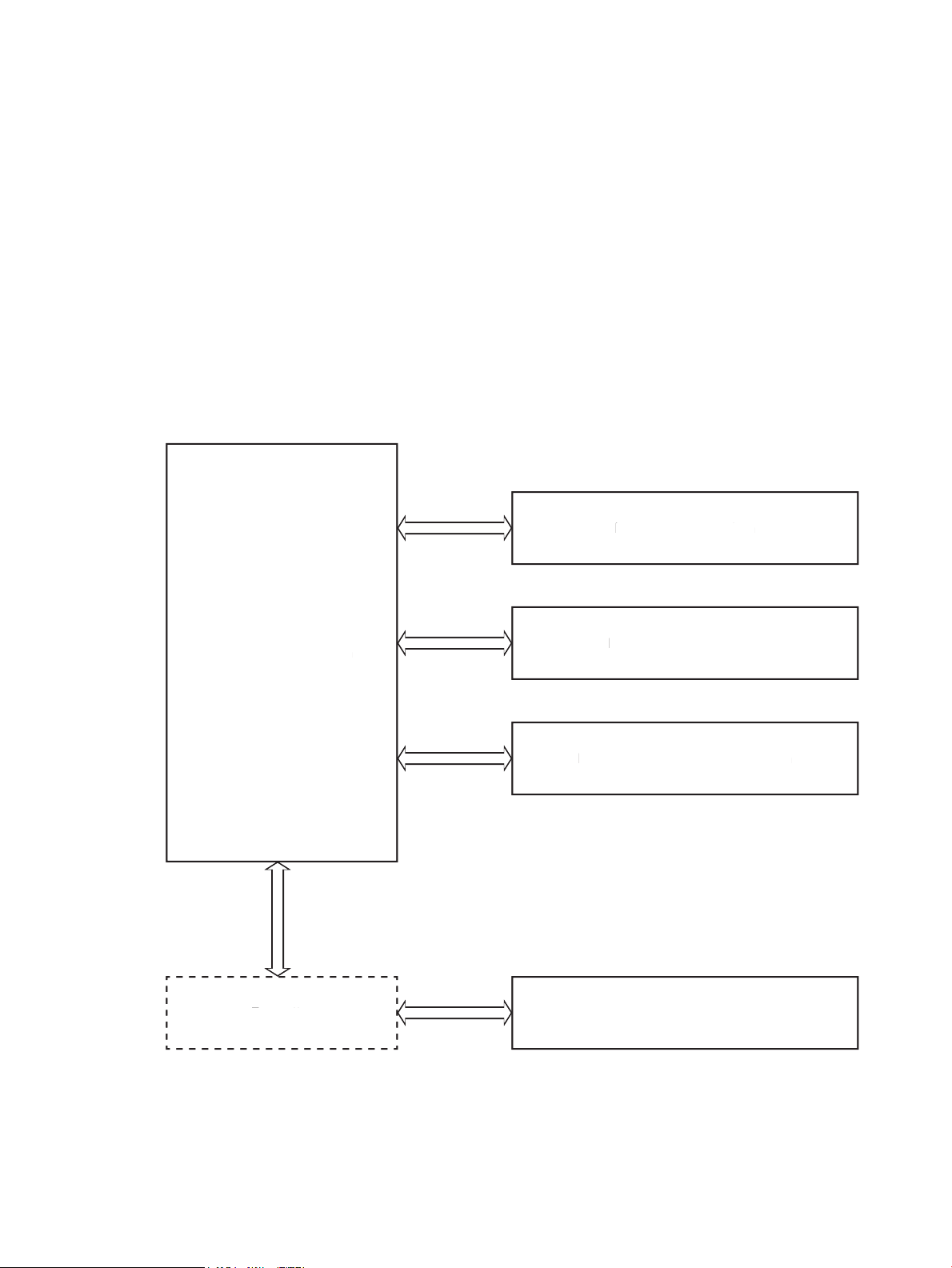
Figure 1-1 Relationship between the main printer systems ............................................................................................... 3
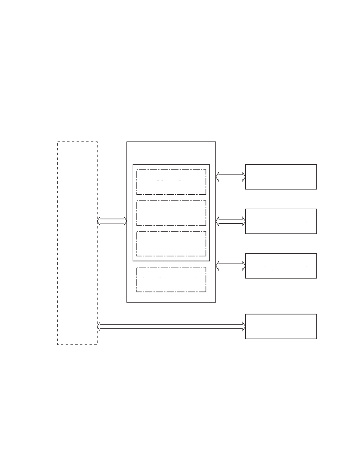
Figure 1-2 Engine-control system ........................................................................................................................................ 8
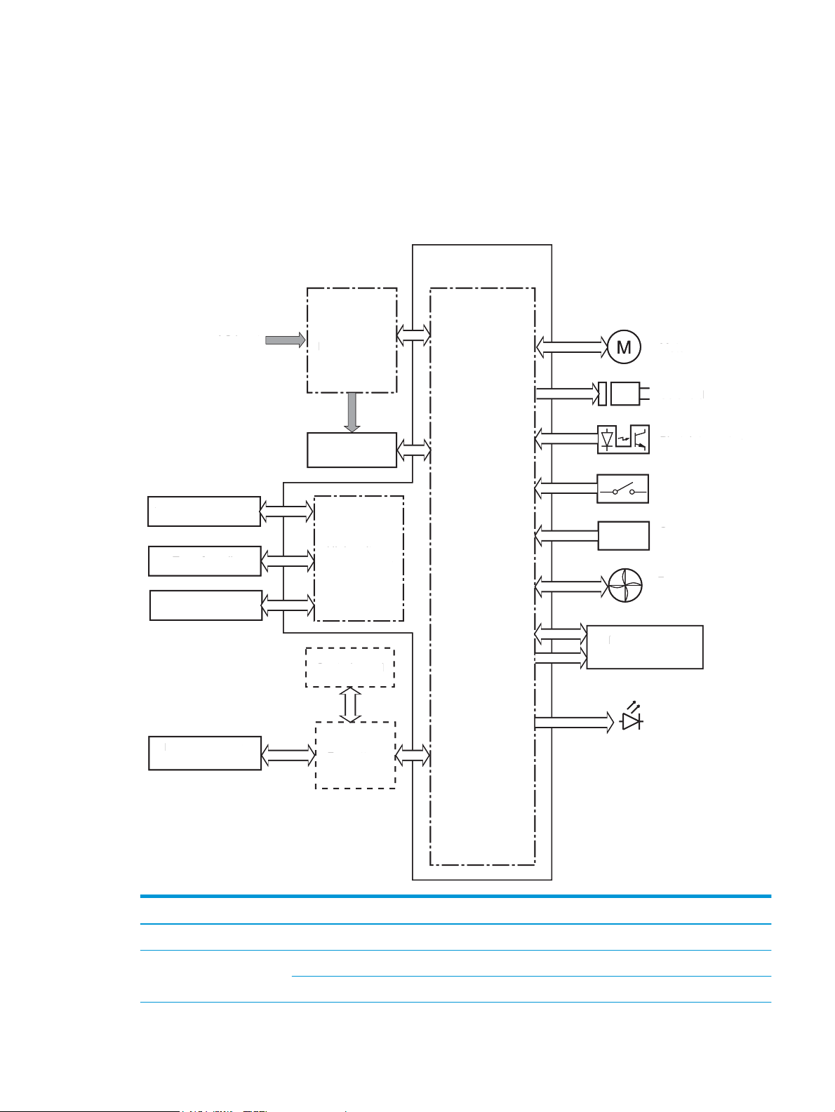
Figure 1-3 DC controller block diagram ............................................................................................................................... 9
Figure 1-4 Low-voltage power-supply circuit ................................................................................................................... 13
Figure 1-5 High-voltage power supply circuits .................................................................................................................. 15
Figure 1-6 Fuser components ............................................................................................................................................ 16
Figure 1-7 Fuser control ..................................................................................................................................................... 17
Figure 1-8 Laser scanner system ....................................................................................................................................... 19
Figure 1-9 Image-formation system .................................................................................................................................. 21
Figure 1-10 Main motor (M1) and image formation components ..................................................................................... 22
Figure 1-11 Sensors ............................................................................................................................................................ 23
Figure 1-12 Image-formation process ............................................................................................................................... 23
Figure 1-13 Pre-exposure .................................................................................................................................................. 24
Figure 1-14 Primary charging ............................................................................................................................................ 25
Figure 1-15 Laser-beam exposure ..................................................................................................................................... 26
Figure 1-16 Development .................................................................................................................................................. 26
Figure 1-17 Primary transfer ............................................................................................................................................. 27
Figure 1-18 Separation ....................................................................................................................................................... 28
Figure 1-19 Fusing .............................................................................................................................................................. 28
Figure 1-20 Drum cleaning ................................................................................................................................................. 29
Figure 1-21 ODT cartridge configuration ........................................................................................................................... 30
Figure 1-22 PT cartridge configuration .............................................................................................................................. 30
Figure 1-23 Pickup, feed, and delivery system .................................................................................................................. 32
Figure 1-24 Sensors and switches for the pickup, feed, and delivery system .................................................................. 34
Figure 1-25 Motors and solenoids ..................................................................................................................................... 35
Figure 1-26 Jam detection sensors .................................................................................................................................... 36
Figure 1-27 Image scanner model block diagram ............................................................................................................. 38
Figure 1-28 Integrated scanner assembly model block diagram ..................................................................................... 39
Figure 1-29 Motor and sensors .......................................................................................................................................... 40
Figure 2-1 Engine test page ............................................................................................................................................... 55
Figure 2-2 Sensors and switches (image formation system; printer base) ...................................................................... 56
Figure 2-3 Sensors (pickup, feed, and delivery system; printer base) .............................................................................. 57
ENWW xvii

Figure 2-4 Service parts (cross section; printer base) ....................................................................................................... 58
Figure 2-5 Image formation (cross section; printer base) ................................................................................................. 59
Figure 2-6 Motor (cross section; printer base) ................................................................................................................... 60
Figure 2-7 Engine controller PCA connectors .................................................................................................................... 61
Figure 2-8 Formatter PCA (M101/M106) ............................................................................................................................ 62
Figure 2-9 Formatter PCA (M129/M134) ............................................................................................................................ 63
Figure 2-10 External plug and port locations (M101/M106) ............................................................................................. 64
Figure 2-11 External plug and port locations (M129/M134) ............................................................................................. 65
Figure 2-12 Main assemblies .............................................................................................................................................. 66
Figure 2-13 Main parts (printer base) ................................................................................................................................ 67
Figure 2-14 PCAs (printer base) ......................................................................................................................................... 67
Figure 2-15 General timing chart ....................................................................................................................................... 68
Figure 2-16 General circuit diagram ................................................................................................................................... 69
Figure 2-17 Sample configuration report .......................................................................................................................... 75
Figure 2-18 Print mode and optimize EWS page ............................................................................................................. 134
Figure 2-19 Repetitive image defect ruler ....................................................................................................................... 142
Figure 2-20 Examples of repetitive defects .................................................................................................................... 144
Figure 2-21 Place the ruler on the page .......................................................................................................................... 145
Figure 2-22 Locate the next repetitive defect ................................................................................................................. 145
Figure 2-23 Determine the defective assembly .............................................................................................................. 146
Figure 2-24 OPC short ...................................................................................................................................................... 147
Figure 2-25 White blotches .............................................................................................................................................. 148
Figure 2-26 OPC drum ghost ............................................................................................................................................ 149
Figure 2-27 Toner block contamination .......................................................................................................................... 150
Figure 2-28 Cartridge coupling (1 of 2) ............................................................................................................................ 151
Figure 2-29 Cartridge coupling (2 of 2) ............................................................................................................................ 152
Figure 2-30 Toner contamination .................................................................................................................................... 153
Figure 2-31 Vertical streaks ............................................................................................................................................. 154
Figure 2-34 Printer base jam sensors .............................................................................................................................. 170
Figure 2-35 Printer base jam sensors .............................................................................................................................. 181
Figure 2-36 Document feeder jam sensors ..................................................................................................................... 182
Figure A-1 Certificate of volatility M102/M103/M104/M106 (1 of 2) ............................................................................. 233
Figure A-2 Certificate of volatility M102/M103/M104/M106 (2 of 2) ............................................................................. 234
Figure A-3 Certificate of volatility M130/M131/M132/M134 base models (1 of 2) ....................................................... 235
Figure A-4 Certificate of volatility M130/M131/M132/M134 base models (2 of 2) ....................................................... 236
Figure A-5 Certificate of volatility M130//M131/M132/M134 models (1 of 2) .............................................................. 237
Figure A-6 Certificate of volatility M130//M131/M132/M134 models (2 of 2) .............................................................. 238
xviii ENWW

1 Theory of operation
●
Related documentation and software
●
Basic operation
●
Formatter-control system
●
Engine-control system
●
Engine laser scanner system
●
Engine pickup, feed, and delivery system
●
Scanning and image capture system (MFP printers)
●
Document feeder system (MFP printers)
●
Fax functions and operation (fax models only)
ENWW 1

Related documentation and software
HP service personnel, go to the Services Access Workbench (SAW) at http://h41302.www4.hp.com/km/saw/
home.do.
Channel partners, go to HP Channel Services Network (CSN) at https://h30125.www3.hp.com/hpcsn.
2 Chapter 1 Theory of operation ENWW
Basic operation
Engine-control system
Formatter
Laser scanner system
Image-formation system
Pickup, feed, and delivery system
Scanning and image capture system (M129-M134)
Engine-control system
Formatter
Laser scanner system
Image-formation system
Pickup, feed, and delivery system
S
canning and image capture system (M129-M134
)
The printer routes all high-level processes through the formatter, which stores font information, processes
the print image, and communicates with the host computer.
The basic printer operation comprises the following systems:
●
Engine-control system
●
Laser scanner system
●
Image-formation system
●
Pickup, feed, and delivery system
●
Scanning and image capture system (M129–M134)
Figure 1-1 Relationship between the main printer systems
ENWW Basic operation 3

Sequence of operation
The DC controller PCA controls the operating sequence, as described in the following table.
Table 1-1 Sequence of operation
Period Duration Description
Waiting From the time the power is turned on, the door is
closed, or when the printer exits sleep mode until the
printer is ready for printing.
Standby From the end of the waiting sequence or the last
rotation until the formatter receives a print command,
or until the printer is turned off.
Initial rotation From the time the formatter receives a print
command until the paper enters the paper path.
Printing From the time the first sheet of paper enters the
paper path until the last sheet passes through the
fuser.
●
Heats the fuser film in the fuser
●
Detects the presence of the toner cartridge
●
Rotates and stops the main motor
●
Cleans the transfer roller
●
Separates the developer roller
●
Remains in the Ready state
●
Enters Active OFF mode if a power control mode
designation command is sent
●
Rotates the main motor
●
Activates the high-voltage power supply (highvoltage bias)
●
Prepares the laser scanner unit
●
Warms the fuser to the correct temperature
●
Engages the developer roller
●
Forms the image on the photosensitive drum
●
Transfers the toner to the paper
●
Fuses the toner image onto the paper
Last rotation From the time the last sheet of paper exits the fuser
until the motors stop rotating.
●
Stops the main motor
●
Stops the high-voltage power supply (highvoltage bias)
●
Stops the laser scanner unit
●
Turns the fuser heater off
●
Separates the developer roller
●
If another print command is received, the printer
enters the initial rotation period when the last
rotation is complete.
4 Chapter 1 Theory of operation ENWW

Formatter-control system
The formatter performs the following functions:
●
Controls the sleep delay function
●
Receives and processes print data from the various printer inputs
●
Monitors control-panel functions and relays printer status information (through the control panel and
the bidirectional input/output)
●
Develops and coordinates data placement and timing with the DC controller
●
Communicates with the host computer through the network or the bidirectional interface
The formatter receives a print job from the network or bidirectional interface and separates it into image
information and instructions that control the printing process. The DC controller synchronizes the image
formation system with the paper input and output systems, and then signals the formatter to send the print
image data.
Sleep delay
When the printer is in sleep delay mode, the control-panel backlight is turned off, but the printer retains all
printer settings, downloaded fonts, and macros. The default setting is a 15-minute idle time. The setting can
be changed or turned off from the control panel menus.
The printer exits sleep delay mode and enters the warm-up cycle when any of the following occurs.
●
A print job, valid data, or a PML or PJL command is received at the serial port.
●
The control panel is touched (button press or touchscreen touch depending on model).
●
A document is loaded in the document feeder or the scanner lid is opened (M129/M134).
●
A tray is opened.
TIP: Error messages override the sleep delay message. The printer enters sleep mode at the appropriate
time, but the error message continues to appear.
Printer job language (PJL)
PJL is an integral part of printer configuration, in addition to the printer control language mobility (PCLM),
printer working group (PWG) raster, and PostScript (PS). With standard cabling, the printer can use PJL to
perform a variety of functions.
●
Dynamic I/O switching: The printer can be configured with a host on each I/O by using dynamic I/O
switching. Even when the printer is offline, it can receive data from more than one I/O simultaneously,
until the I/O buffer is full.
●
Context-sensitive switching: The printer can automatically recognize the personality (PS or PCLM) of
each job and configure itself to serve that personality.
●
Isolation of print environment settings from one print job to the next: For example, if a print job is
sent to the printer in landscape mode, the subsequent print jobs print in landscape only if they are
formatted for landscape printing.
ENWW Formatter-control system 5

Printer management language (PML)
PML allows remote configuration of the printer and status monitoring through the input/output (I/O) ports.
Control panel
The formatter sends and receives printer status and command data to and from the control panel.
Wireless
NOTE: Wireless models only.
Wireless products contain a wireless card to enable 802.11b/g/n wireless communication.
Low end data model (LEDM) overview
The low-end data model (LEDM) provides one consistent data representation method and defines the
dynamic and capabilities tickets shared between clients and devices, as well as the access protocol, event,
security, and discovery methods.
Advanced control language (ACL) overview
The advanced control language (ACL) is a language that supports printer control and firmware downloads in
printers that support both PJL/PCL and host-based printing. Each sequence of ACL commands must be
preceded by a unified exit command (UEL) and an @PJL ENTER LANGUAGE=ACL command. The ACL sequence
is always followed by a UEL. Any number of commands can be placed between the UELs. The only exception
to these rules is the download command. If a firmware download is done, the download command must be
the last command in the sequence. It will not be followed by a UEL.
The firmware searches for the UEL sequence when parsing commands. However, while downloading binary
data such as host-based code or NVRAM data, the firmware suspends UEL parsing. To handle hosts that
“disappear” during binary sequences, the firmware times out all ACL command sessions. If a timeout occurs
during a non-download command sequence, it is treated as the receipt of a UEL. If a timeout occurs during
firmware download, the printer resets.
CPU
The formatter incorporates a 600 MHz processor.
Input/output (I/O)
The following sections discuss the input and output features of the printer.
USB
The printer includes a universal serial bus (USB) 2.0 connection.
USB hosts
The printer includes USB hosts for USB flash drive and wireless communication control.
10/100 networking
The printer includes a 10/100 network (Ethernet) connection.
6 Chapter 1 Theory of operation ENWW

Fax
NOTE: M129-M134 models only.
The printer includes a fax phone line connection.
Memory
If the printer encounters a problem when managing available memory, a clearable warning message appears
on the control panel.
Firmware
The formatter stores the printer firmware. A remote firmware upgrade process is used to overwrite and
upgrade the firmware.
Nonvolatile random access memory (NVRAM)
The printer uses nonvolatile memory (NVRAM) to store I/O and information about the print environment
configuration. The contents of NVRAM are retained when the printer is turned off or disconnected.
Flash memory
DRR: Stores microprocessor control programs.
NAND: Stores fax memory (M129/M134 models only) and driver installation software.
Random access memory
DDR memory
●
128 MB (M101/M129 base model)
●
256 MB (all other models)
Flash memory
●
16 MB NOR (M101/M106 and M129 base model)
●
256 MB NAND flash (all other models)
HP Memory Enhancement technology (MEt)
The HP Memory Enhancement technology (MEt) effectively doubles the standard memory through a variety
of font- and data-compression methods.
NOTE: The MEt is available only in PCL mode; it is not functional when printing in PS mode.
ENWW Formatter-control system 7
Engine-control system
Formatter
Engine-control system
Engine controller
DC controller
High-voltage power supply
Laser scanner system
Image-formation system
Pickup, feed, and delivery
system
Low-voltage power supply
Fuser control
Scanning and image
capture system (M129-M134)
Formatter
Engine-control system
Engine controller
DC controller
igh-voltage power suppl
y
Laser scanner system
Image-formation system
Pickup, feed, and delivery
stem
Low-voltage power suppl
y
F
user co
ntrol
canning and image
apture system (M129-M134
)
The engine-control system receives commands from the formatter and interacts with the other main
systems to coordinate all printer functions. The engine-control system consists of the following components:
●
DC controller
●
Low-voltage power supply
●
High-voltage power supply
●
Fuser power supply
Figure 1-2 Engine-control system
8 Chapter 1 Theory of operation ENWW
DC controller
Transfer front guide
High-voltage
power supply
Fan
Cartridge
LED
Motor
Solenoid
Switch
Photointerrupter
Formatter
Control panel
Laser scanner
assembly
Fuser
AC input
Low-voltage
power supply
DC controller
Sensor
Engine controller
Transfer roller
Image Scanner
(M129–M134)
Transfer front guid
e
igh-volta
ge
ower suppl
y
F
an
artrid
ge
LED
tor
olenoi
d
witc
h
Photointerrupter
Formatter
ontrol panel
L
aser scanne
r
assembl
y
F
use
r
AC inpu
t
Low-volta
ge
ower suppl
y
DC controller
ensor
Engine controller
Transfer roller
Image Scanner
M129–M134
)
The DC controller controls the operation of the printer and its components. The DC controller starts the
printer operation when the printer power is turned on and the power supply sends DC voltage to the DC
controller. After the printer enters the standby period, the DC controller sends out various signals to operate
motors, solenoids, and other printer components based on the print command and image data that the host
computer sends.
Figure 1-3 DC controller block diagram
Component type Abbreviation Description
Motor M1 Main motor
Solenoid SL1 Pickup solenoid
SL2 Developer alienation solenoid
ENWW Engine-control system 9

Component type Abbreviation Description
Switch SW1 Developer alienation switch
SW501 Cartridge door switch
SW740 Power switch
Photointerrupter PS601 Main motor rotation number sensor
SR760 Top of page (TOP) sensor
SR770 Media out sensor
SR771 Pickup media width sensor
SR780 Fuser output sensor
SR781 Fuser media width sensor
Sensor - Environment sensor
- Toner level sensor (M105-M106 and M133-M134 models)
LED LED391 Pre-exposure LED
LED740 Power supply LED
10 Chapter 1 Theory of operation ENWW
 Loading...