

Page 1
HP LaserJet P2010 Series
Service Manual
Page 2

Page 3

HP LaserJet P2010 Series
Service Manual
Page 4

Copyright information
Safety information
Trademark credits
© 2007 Copyright Hewlett-Packard
Development Company, L.P.
Reproduction, adaptation, or translation
without prior written permission is
prohibited, except as allowed under the
copyright laws.
The information contained herein is subject
to change without notice.
The only warranties for HP products and
services are set forth in the express
warranty statements accompanying such
products and services. Nothing herein
should be construed as constituting an
additional warranty. HP shall not be liable
for technical or editorial errors or omissions
contained herein.
Part Number: CB450-90967
Edition 1, 03/2007
WARNING!
Potential Shock Hazard
Always follow basic safety precautions
when using this product to reduce risk of
injury from fire or electric shock.
Read and understand all instructions in the
user guide.
Observe all warnings and instructions
marked on the product.
Use only a grounded electrical outlet when
connecting the printer to a power source. If
you do not know whether the outlet is
grounded, check with a qualified electrician.
Do not touch the contacts on the end of
any of the sockets on the printer. Replace
damaged cords immediately.
Unplug this product from wall outlets
before cleaning.
Do not install or use this product near
water or when you are wet.
Install the product securely on a stable
surface.
PostScript® 3™ is a trademark of Adobe
Systems Incorporated.
Microsoft®, Windows®, and Windows XP®
are U.S. registered trademarks of Microsoft
Corporation.
Energy Star® and the Energy Star logo®
are U.S. registered marks of the United
States Environmental Protection Agency.
Install the product in a protected location
where no one can step on or trip over the
power cord and where the power cord will
not be damaged.
If the product does not operate normally,
see the online user guide.
Refer all servicing questions to qualified
personnel.
Information regarding FCC Class B, Parts
15 and 68 requirements can be found in
the user guide.
Page 5

Table of contents
1 Product basics
Product features .................................................................................................................................... 2
Standard features ................................................................................................................. 2
Network model features ........................................................................................................ 2
Identify product parts ............................................................................................................................. 3
Control panel ......................................................................................................................................... 5
Supported paper and other media ......................................................................................................... 6
Understand paper and print media use ................................................................................ 6
Supported paper and print media sizes ................................................................................ 6
Custom paper sizes .............................................................................................................. 7
Special paper or print media guidelines ............................................................................... 7
Load media ............................................................................................................................................ 9
Tray 1 .................................................................................................................................... 9
Tray 2 and optional tray 3 ..................................................................................................... 9
Straight-through output path ............................................................................................... 10
Manual feed ........................................................................................................................ 10
2 Installation
Site preparation ................................................................................................................................... 12
Package contents ................................................................................................................................ 13
Install tray 3 ......................................................................................................................................... 14
Printer connections .............................................................................................................................. 15
Software for Windows .......................................................................................................................... 17
Software for Macintosh ........................................................................................................................ 19
USB and parallel connections ............................................................................................. 15
Network connections ........................................................................................................... 15
Connect the printer to the network ..................................................................... 16
Install the printer software for the network printer .............................................. 16
Supported operating systems ............................................................................................. 17
Windows printer drivers ...................................................................................................... 17
Windows driver types ......................................................................................... 17
Install Windows software .................................................................................... 17
To install printer software for Windows NT 4.0, Server 2003 (64-
bit), Windows 98SE, Me, and XP (64-bit) .......................................... 17
To install printer software for Windows 2000, XP (32-bit), Server
2003 (32-bit), and Vista (32-bit) ........................................................ 17
Configure the Windows printer driver ................................................................. 17
Macintosh printer drivers .................................................................................................... 19
Install the Macintosh printer driver ..................................................................... 19
ENWW iii
Page 6

PostScript Printer Description files (PPDs) ......................................................................... 20
Printer information pages .................................................................................................................... 21
Demo page ......................................................................................................................... 21
Configuration page .............................................................................................................. 21
Supplies Status page .......................................................................................................... 21
3 Manage the printer
Embedded Web server (network model only) ..................................................................................... 24
Open the embedded Web server ........................................................................................ 24
Information tab .................................................................................................................... 25
Settings tab ......................................................................................................................... 25
Networking tab .................................................................................................................... 25
Links .................................................................................................................................... 25
4 Maintenance
Replace the print cartridge .................................................................................................................. 28
Redistribute toner ................................................................................................................................ 30
Clean the printer .................................................................................................................................. 31
Clean the print-cartridge area ............................................................................................. 31
Clean the printer media path .............................................................................................. 33
Clean the pickup roller (tray 1) ............................................................................................................ 34
Replace the pickup roller (tray 1) ........................................................................................................ 39
Clean the pickup roller (tray 2) ............................................................................................................ 44
Replace the pickup roller (tray 2) ........................................................................................................ 51
EconoMode .......................................................................................................................................... 57
Configure the Macintosh printer driver ............................................................... 19
5 Theory of operation
Introduction .......................................................................................................................................... 60
Internal components ............................................................................................................................ 61
Timing .................................................................................................................................................. 63
Engine control system ......................................................................................................................... 64
Laser/scanner system ..........................................................................................................
Pickup/feed/delivery system ................................................................................................................ 67
Image-formation system ...................................................................................................................... 69
6 Removal and replacement
Introduction .......................................................................................................................................... 74
Removal and replacement strategy .................................................................................... 74
Electrostatic discharge ........................................................................................................ 74
Required tools ..................................................................................................................... 74
Before performing service ................................................................................................................... 75
Pre-service procedures ....................................................................................................... 75
Parts removal order ............................................................................................................ 75
Covers ................................................................................................................................................. 76
Left-side cover .................................................................................................................... 76
Right-side cover .................................................................................................................. 76
Back cover .......................................................................................................................... 77
Top cover ............................................................................................................................ 78
............... 66
iv ENWW
Page 7

Control panel ....................................................................................................................................... 83
Formatter ............................................................................................................................................. 85
Laser/scanner ...................................................................................................................................... 86
Memory-tag-reader assembly .............................................................................................................. 87
Fuser .................................................................................................................................................... 89
Interlock assembly ............................................................................................................................. 100
ECU ................................................................................................................................................... 101
Main motor ......................................................................................................................................... 108
Pickup and feed assemblies .............................................................................................................. 110
Main gear assembly/tray 2 pickup solenoid ...................................................................................... 115
Print-cartridge door ............................................................................................................................ 119
7 Problem solving
Basic problem solving ........................................................................................................................ 122
Status-light patterns ........................................................................................................................... 124
Media problem solving ....................................................................................................................... 135
Printed page is different than what appeared on screen .................................................................. 137
Improve print quality .......................................................................................................................... 139
Clear jams .......................................................................................................................................... 144
Diagnostic resources ......................................................................................................................... 152
Fan ...................................................................................................................................... 89
Fuser ................................................................................................................................... 90
Transfer roller .................................................................................................................... 110
Registration assembly ...................................................................................................... 111
Primary status-light patterns ............................................................................................. 124
Fatal error secondary messages ...................................................................................... 130
Accessory error secondary messages ............................................................................. 134
Garbled, incorrect, or incomplete text ............................................................................... 137
Missing graphics or text, or blank pages .......................................................................... 137
Page format is different than on another HP LaserJet printer .......................................... 138
Graphics quality ................................................................................................................ 138
Light print or faded ............................................................................................................ 139
Toner specks ..................................................................................................................
Dropouts ........................................................................................................................... 139
Vertical lines ...................................................................................................................... 140
Gray background .............................................................................................................. 140
Toner smear ...................................................................................................................... 140
Loose toner ....................................................................................................................... 141
Vertical repetitive defects .................................................................................................. 141
Misformed characters ....................................................................................................... 141
Page skew ........................................................................................................................ 142
Curl or wave ...................................................................................................................... 142
Wrinkles or creases .......................................................................................................... 142
Toner scatter outline ......................................................................................................... 143
Repetitive image defects .................................................................................................. 143
Print-cartridge area ........................................................................................................... 144
Input trays ......................................................................................................................... 146
Output bin ......................................................................................................................... 149
Straight-through output path ............................................................................................. 150
Engine test ........................................................................................................................ 152
.. 139
ENWW v
Page 8

Continuous self-test .......................................................................................................... 152
Half self-test functional check ........................................................................................... 153
Drum rotation functional check ........................................................................................ 153
Heating element check ..................................................................................................... 153
High-voltage contacts check ............................................................................................. 154
Printer software problems .................................................................................................................. 156
Network-setup problem-solving ......................................................................................................... 157
Reset the printer ................................................................................................................................ 158
NVRAM initialization ......................................................................................................... 158
Super NVRAM initialization ............................................................................................... 158
Network reset .................................................................................................................... 159
Cold reset .......................................................................................................................... 159
Troubleshooting tools and reference diagrams ................................................................................. 160
General timing chart ......................................................................................................... 160
Circuit diagram .................................................................................................................. 161
Solenoids .......................................................................................................................... 163
Switches and sensors ....................................................................................................... 164
Rollers and pads ............................................................................................................... 165
8 Parts and diagrams
Assembly locations ............................................................................................................................ 168
Covers ............................................................................................................................................... 172
Internal assemblies ............................................................................................................................ 176
Alphabetical parts list ......................................................................................................................... 202
Numerical parts list ............................................................................................................................ 212
Checking the print cartridge contacts ............................................................ 154
Checking the high-voltage connector assembly ............................................. 155
Appendix A Accessory/Consumable addendum
Order parts and supplies ................................................................................................................... 224
Parts .................................................................................................................................. 224
Related documentation and software ............................................................................... 224
Supplies ............................................................................................................................ 224
Order parts, accessories, and supplies ........................................................................................
Order directly from HP ...................................................................................................... 225
Order through service or support providers ...................................................................... 225
Order directly through the embedded Web server ........................................................... 225
Supplies and accessories table ......................................................................................................... 226
10/100 networking print servers ........................................................................................................ 227
HP print cartridges ............................................................................................................................. 228
HP policy on non-HP print cartridges ............................................................................... 228
Storing print cartridges ...................................................................................................... 228
Print cartridge life expectancy ........................................................................................... 228
Saving toner ...................................................................................................................... 228
Appendix B Service and support
Hewlett-Packard limited warranty statement ..................................................................................... 230
Limited warranty for print cartridges and image drums ..................................................................... 231
Hewlett-Packard software license agreement ................................................................................... 232
..... 225
vi ENWW
Page 9

HP Customer Care ............................................................................................................................ 233
Availability of support and service ..................................................................................................... 235
HP Care Pack™ Services and Service Agreements ........................................................ 235
Guidelines for repacking the printer .................................................................................................. 236
Appendix C Printer specifications
Physical specifications ....................................................................................................................... 238
Electrical specifications ..................................................................................................................... 238
Acoustic emissions ............................................................................................................................ 239
Environmental specifications ............................................................................................................. 240
Printer capacities and ratings ............................................................................................................ 241
Memory specifications ....................................................................................................................... 241
Port availability ................................................................................................................................... 241
Appendix D Regulatory information
FCC compliance ................................................................................................................................ 244
Environmental product stewardship program .................................................................................... 245
Protecting the environment ............................................................................................... 245
Ozone production .............................................................................................................. 245
Power consumption .......................................................................................................... 245
Toner consumption ........................................................................................................... 245
Paper use .......................................................................................................................... 245
Plastics .............................................................................................................................. 245
HP LaserJet print supplies ................................................................................................ 245
Return and recycling instructions ..................................................................................... 246
United States and Puerto Rico ......................................................................... 246
Non-US returns ................................................................................................ 246
Paper ................................................................................................................................. 246
Material restrictions ........................................................................................................... 247
Disposal of waste equipment by users in private households in the European Union .... 247
Material Safety Data Sheet (MSDS) ................................................................................. 247
For more information ........................................................................................................ 247
Declaration of Conformity statements ............................................................................................... 248
Regulatory statements ....................................................................................................................... 249
Laser safety statement ..................................................................................................... 249
Canadian DOC regulations ............................................................................................... 249
Korean EMI statement ...................................................................................................... 249
Laser statement for Finland .............................................................................................. 250
Multiple returns (two to eight cartridges) ......................................... 246
Single returns .................................................................................. 246
Shipping ........................................................................................... 246
Index .................................................................................................................................................................. 251
ENWW vii
Page 10

viii ENWW
Page 11

1 Product basics
This chapter provides information on the following topics:
Product features
●
Identify product parts
●
Control panel
●
Supported paper and other media
●
Load media
●
ENWW 1
Page 12

Product features
The following are the standard features for this product.
Standard features
24 ppm (Letter-size), 23 ppm (A4–size)
●
First page out in as few as 8.5 seconds
●
600 dpi (provides 600 x 600 dpi output with Resolution Enhancement Technology (REt) for
●
improved text)
FastRes 1200 (provides 1200 dpi effective output quality)
●
ProRes 1200 (provides fine line detail at 1200 x 1200 dpi)
●
50-sheet multipurpose tray (tray 1)
●
EconoMode
●
Print watermarks, booklets, multiple pages per sheet (N-up), and first page on different media
●
than the rest of the document
32 MB RAM
●
3,000-page or 7,000-page print cartridge
●
Host-based, PCL 5e
●
Compatible with USB 2.0 specifications
●
Supported by Windows® 98 SE (PCL 5e printer driver only), Millennium Edition (Me) (PCL 5e
●
printer driver only), NT® 4.0 (PCL 5e printer driver only) (Parallel connection only), 2000,
Server 2003 (printer drivers only), XP® 32-bit, XP 64-bit (PCL 5e printer driver only), and Vista
32-bit
Supported by Macintosh OS X v10.2.8, v10.3, v10.4 and later
●
On/off switch
●
Embedded Web server (EWS) with internal pages
●
26 PCL 5e fonts
●
Network model features
Products with the network feature include all of the standard features, except that it has an HP
internal IPv6-compatible network port instead of a parallel port.
2 Chapter 1 Product basics ENWW
Page 13
Identify product parts
The following figures identify the components of the product.
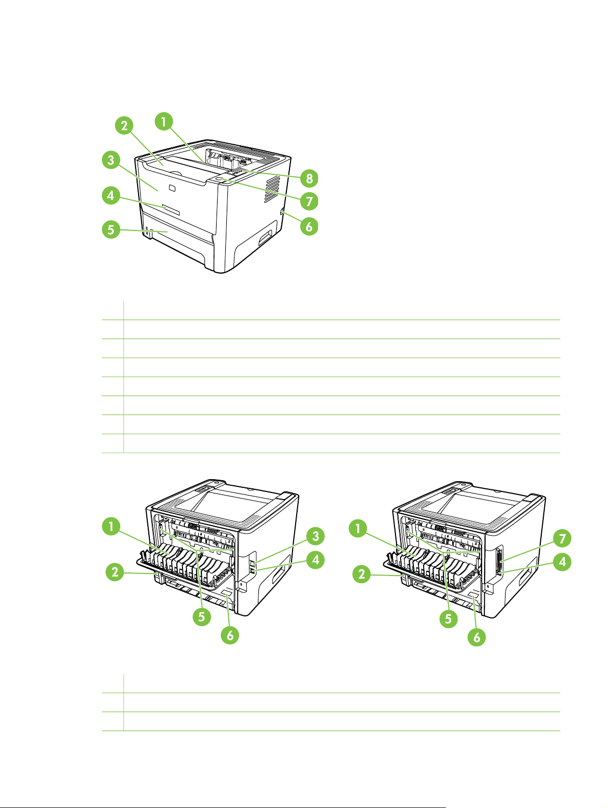
Figure 1-1 Network model, front view
1
Output bin
2
Print-cartridge door
3
Tray 1 (50–sheet multipurpose tray)
4
Model number
5
Tray 2 (250-sheet enclosed input tray)
6
On/off switch
7
Print-cartridge-door button
8
Control panel
Figure 1-2 Network and base models, back view
1
Straight-through output door
2
Power receptacle
3
HP internal network port (network-ready models only)
ENWW Identify product parts 3
Page 14

4
USB port
5 Jam-clearing levers
6
Serial number
7
Parallel port (base model only)
4 Chapter 1 Product basics ENWW
Page 15

Control panel
The printer control panel is comprised of six lights and two buttons. The lights produce patterns that
identify the printer status.
1 Jam light: Indicates a jam in the printer
2 Toner light: When the print cartridge is low, the Toner light illuminates. When the print cartridge is out of the printer,
the Toner light blinks.
3 Paper out light: Indicates the printer is out of paper
4 Attention light: Indicates the print cartridge door is open or other errors exist
5 Ready light: Indicates the printer is ready to print
6 Go button and light
7 Cancel button: To cancel the print job currently printing, press the Cancel button.
NOTE: See Status-light patterns on page 124 for a description of the light patterns.
ENWW Control panel 5
Page 16

Supported paper and other media
Understand paper and print media use
This product supports a variety of paper and other print media in accordance with the guidelines in
this user guide. Paper or print media that does not meet these guidelines might cause the following
problems:
Poor print quality
●
Increased jams
●
Premature wear on the product, requiring repair
●
For best results, use only HP-brand paper and print media designed for laserjets or multiuse. Do not
use paper or print media made for inkjet printers. Hewlett-Packard Company cannot recommend the
use of other brands of media because HP cannot control their quality.
It is possible for paper to meet all of the guidelines in this user guide and still not produce satisfactory
results. This might be the result of improper handling, unacceptable temperature and/or humidity
levels, or other variables over which Hewlett-Packard has no control.
CAUTION: Using paper or print media that does not meet Hewlett-Packard's specifications
might cause problems for the product, requiring repair. This repair is not covered by the
Hewlett-Packard warranty or service agreements.
Supported paper and print media sizes
This product supports a number of paper sizes, and it adapts to various media.
NOTE: To obtain best print results, select the appropriate paper size and type in your print
driver before printing.
Table 1-1 Supported paper and print media sizes
Size Dimensions Tray 1 Tray 2 Optional tray 3
Letter 216 x 279 mm (8.5 x 11 inches)
Legal 216 x 356 mm (8.5 x 14 inches)
A4 210 x 297 mm (8.27 x 11.69 inches)
Executive 184 x 267 mm (7.24 x 10.51 inches)
A5 148 x 210 mm (5.83 x 8.27 inches)
A6 105 x 148 mm (4.13 x 5.83 inches)
B5 (JIS) 182 x 257 mm (7.17 x 10.12 inches)
B5 (ISO) 176 x 250 mm (6.93 x 9.84 inches)
B6 (ISO) 125 x 176 mm (4.92 x 6.93 inches)
16k 197 x 273 mm (7.75 x 10.75 inches)
16k 184 x 260 mm (7.24 x 10.23 inches)
16k 195 x 270 mm (7.68 x 10.63 inches)
6 Chapter 1 Product basics ENWW
Page 17

Table 1-1 Supported paper and print media sizes (continued)
Size Dimensions Tray 1 Tray 2 Optional tray 3
8.5 x 13
(custom)
Custom (76 - 216) x (127 - 356) mm ((3 - 8.5) x (5 -
216 x 330 mm (8.5 x 13 inches)
14) inches)
Table 1-2 Supported envelopes and postcards
Size Dimensions Tray 1 Tray 2 Optional tray 3
Envelope #10 105 x 241 mm (4.13 x 9.49 inches)
Envelope DL 110 x 220 mm (4.33 x 8.66 inches)
Envelope C5 162 x 229 mm (6.93 x 9.84 inches)
Envelope B5 176 x 250 mm (6.7 x 9.8 inches)
Envelope
Monarch
Postcard 100 x 148 mm (3.94 x 5.83 inches)
Double
postcard
98 x 191 mm (3.9 x 7.5 inches)
148 x 200 mm (5.83 x 7.87 inches)
Custom paper sizes
This product supports a variety of custom paper sizes. Supported custom sizes are sizes that are
within the minimum- and maximum-size guidelines for the product but are not listed in the supported
paper sizes table. When using a supported custom size, specify the custom size in the print driver,
and load the paper in a tray that supports custom sizes.
Special paper or print media guidelines
This product supports printing on special media. Use the following guidelines to obtain satisfactory
results. When using special paper or print media, be sure to set the type and size in your print driver
to obtain the best print results.
CAUTION: HP LaserJet printers use fusers to bond dry toner particles to the paper in very
precise dots. HP laser paper is designed to withstand this extreme heat. Using inkjet paper
not designed for this technology could damage your printer.
Media type Do Do not
Envelopes ● Store envelopes flat.
Use envelopes where the seam
●
extends all the way to the corner
of the envelope.
Use peel-off adhesive strips that
●
are approved for use in laser
printers.
● Do not use envelopes that are
wrinkled, nicked, stuck together,
or otherwise damaged.
Do not use envelopes that have
●
clasps, snaps, windows, or coated
linings.
Do not use self-stick adhesives or
●
other synthetic materials.
ENWW Supported paper and other media 7
Page 18

Media type Do Do not
Labels
Transparencies
Letterhead or preprinted forms
Heavy paper ● Use only heavy paper that is
Glossy or coated paper
Use only labels that have no
●
exposed backing between them.
Use Labels that lie flat.
●
Use only full sheets of labels.
●
Use only transparencies that are
●
approved for use in laser printers.
Place transparencies on a flat
●
surface after removing them from
the product.
Use only letterhead or forms
●
approved for use in laser printers.
approved for use in laser printers
and meets the weight
specifications for this product.
Use only glossy or coated paper
●
that is approved for use in laser
printers.
Do not use labels that have
●
wrinkles or bubbles, or are
damaged.
Do not print partial sheets of labels.
●
Do not use transparent print
●
media not approved for laser
printers.
Do not use raised or metallic
●
letterhead.
● Do not use paper that is heavier
than the recommended media
specification for this product
unless it is HP paper that has
been approved for use in this
product.
Do not use glossy or coated paper
●
designed for use in inkjet products.
8 Chapter 1 Product basics ENWW
Page 19
Load media
The following sections describe how to load media into the different input trays.
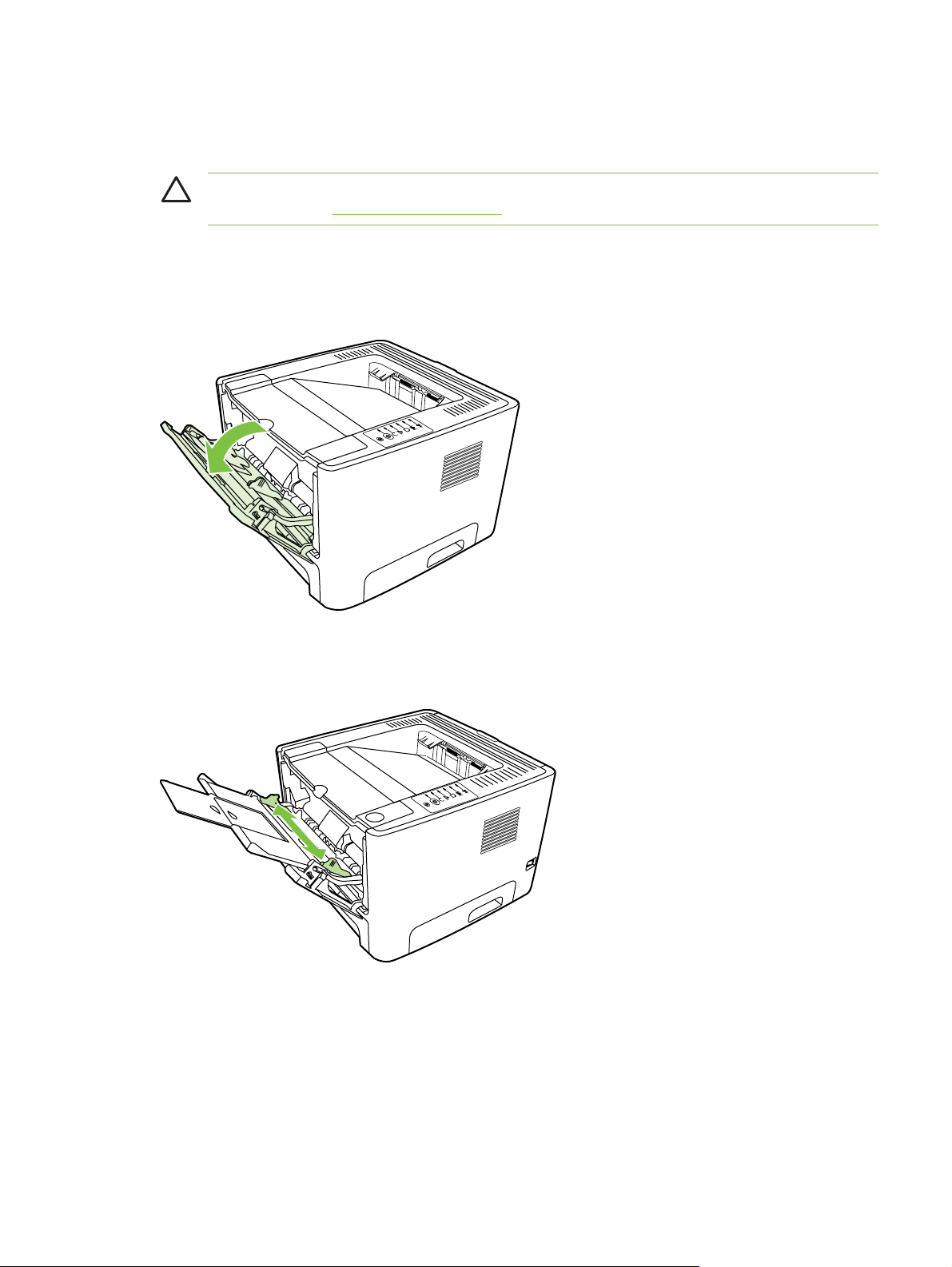
CAUTION: If you try to print on media that is wrinkled, folded, or damaged in any way, a jam
might occur. See
Tray 1
Tray 1 is accessed from the front of the printer. The printer prints from tray 1 before attempting to
print from other trays.
Clear jams on page 144 for more information.
Media guides ensure that the media is correctly fed into the printer and that the print is not skewed
(crooked on the media). When loading media, adjust the media guides to match the width of the
media that you are using.
Tray 2 and optional tray 3
Media guides ensure that the media feeds correctly into the printer and that the print is not skewed.
Tray 2 has side and rear media guides. When loading media, adjust the media guides to match the
length and width of the media that you are using.
ENWW Load media 9
Page 20
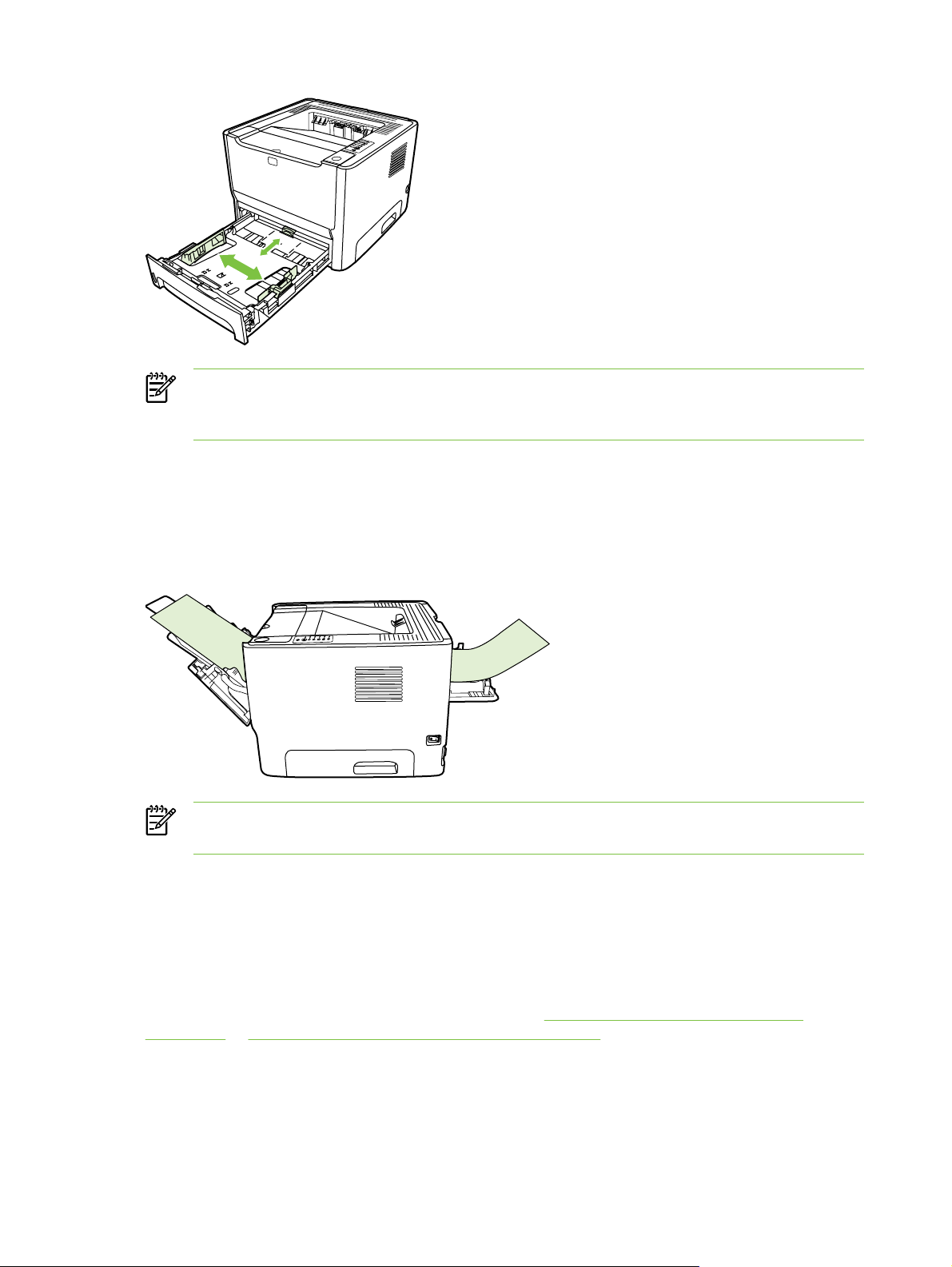
NOTE: When you add new media, make sure that you remove all of the media from the
input tray and straighten the stack of new media. This reduces jams by preventing multiple
sheets of media from feeding through the printer at one time.
Straight-through output path
Use the straight-through output path when printing envelopes, transparencies, heavy media, or any
media that tends to curl when printed. If you open the straight-through output door before printing
media from tray 1, tray 2, or optional tray 3, the media exits the printer through the straight-through
output path.
NOTE: Printed media does not stack when you use the straight-through output path. The
media drops to the surface below unless you remove each sheet as it exits the printer.
Manual feed
You can use manual feed when printing mixed media. For example, you can use manual feed to print
an envelope, then a letter, then an envelope, and so on. Load envelopes in tray 1 and load
letterhead into tray 2.
To print using manual feed, open the printer Properties or Printer Setup, and then select Manual
Feed (tray 1) from the Source Tray drop-down list. See
on page 17 or Configure the Macintosh printer driver on page 19 for instructions. After you have
enabled manual feed, press the Go button to print.
10 Chapter 1 Product basics ENWW
Configure the Windows printer driver
Page 21

2 Installation
Site preparation
●
Package contents
●
Install tray 3
●
Printer connections
●
Software for Windows
●
Software for Macintosh
●
Printer information pages
●
ENWW 11
Page 22

Site preparation
Place the printer on a sturdy, level surface that meets the following environmental requirements:
Temperature: 15°C to 32.5°C (59°F to 90.5°F)
●
Humidity: 10% to 80% relative humidity (no condensation)
●
Exposure: Place away from direct sunlight, open flames, ammonia fumes, and air vents.
●
Clearance: Allow sufficient space around the printer for access.
●
Ventilation: Ensure that the printer is located in a well-ventilated area.
●
12 Chapter 2 Installation ENWW
Page 23
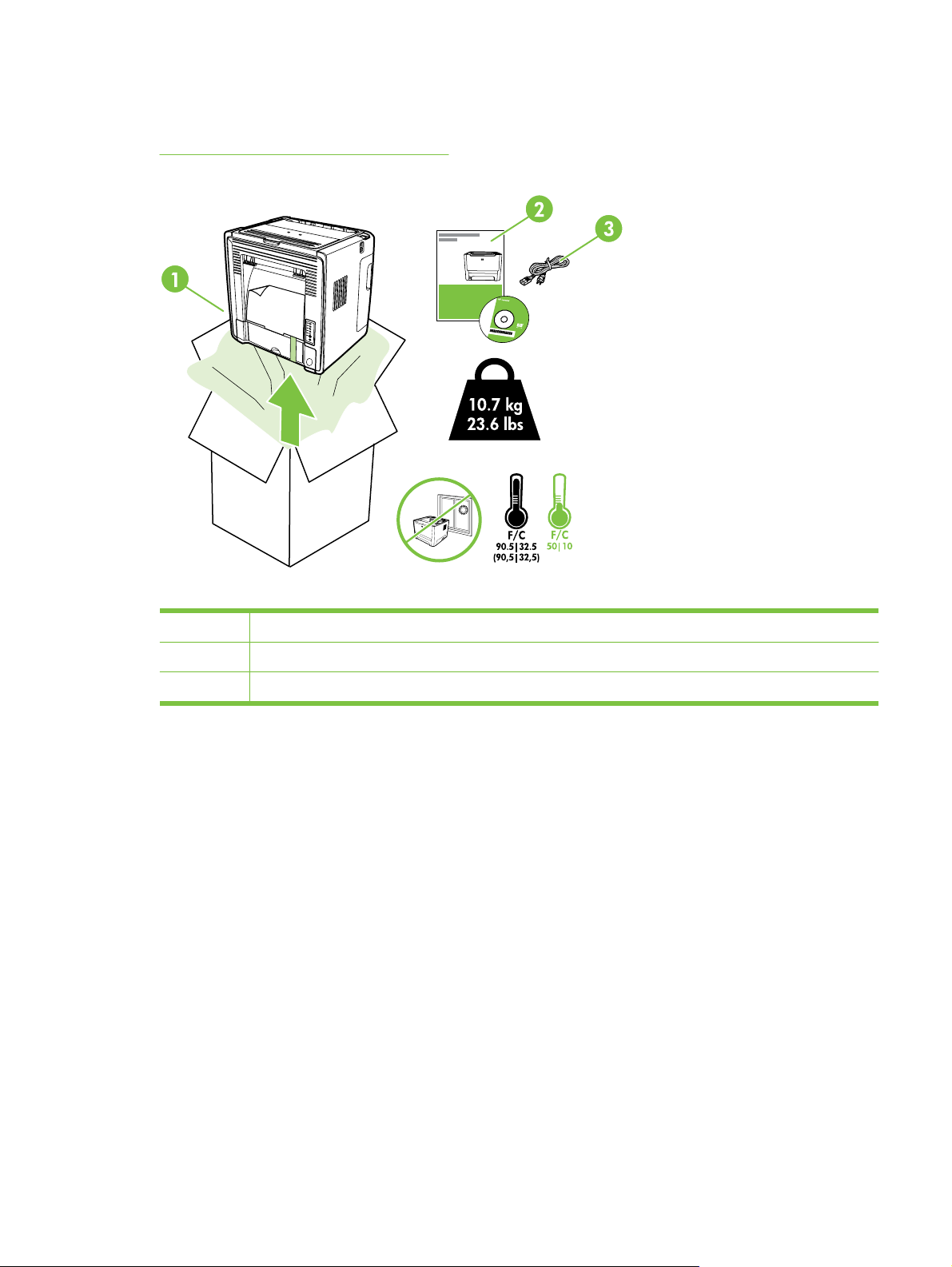
Package contents
Figure 2-1 Package contents on page 13 shows the package contents for the HP LaserJet P2014
Series printer.
Figure 2-1 Package contents
1 HP LaserJet P2015 Series printer
2 Software and user documentation CD-ROM
3 Power cable
ENWW Package contents 13
Page 24
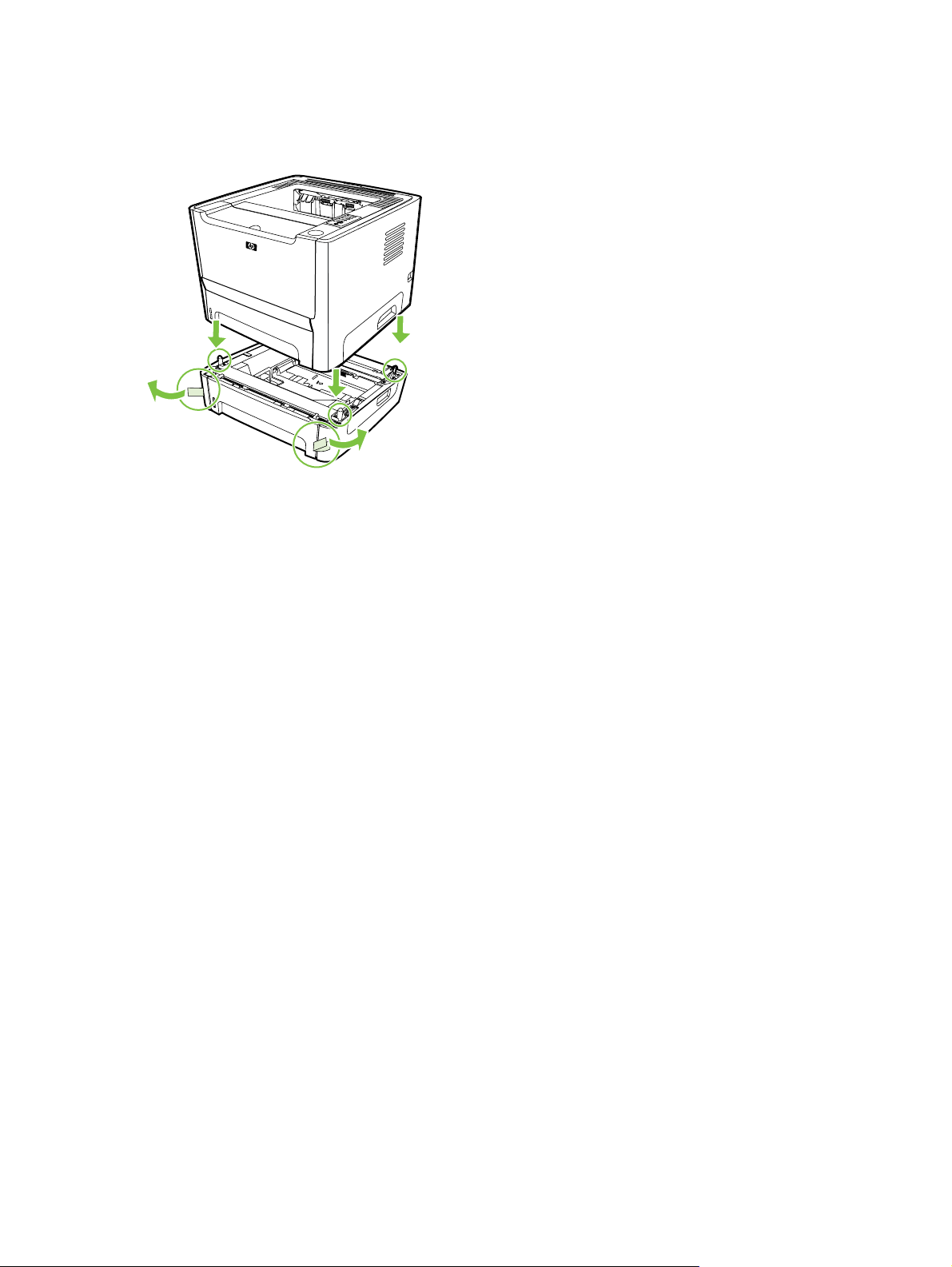
Install tray 3
If you have tray 3, install tray 3 as shown.
Figure 2-2 Installing tray 3
After installing tray 3, configure the printer driver to allow printing from tray 3.
1. On the Windows task bar, click Start, click Settings, and then click Printers.
2. Right-click the HP LaserJet P2014 icon.
3. Click Properties.
4. Click the Device Settings tab.
5. Windows 2000/XP: Under Installable Options, change Tray 3 to Installed.
Windows 98/Me: Click Configure, and then select Tray 3 under Optional Paper Sources.
14 Chapter 2 Installation ENWW
Page 25
Printer connections
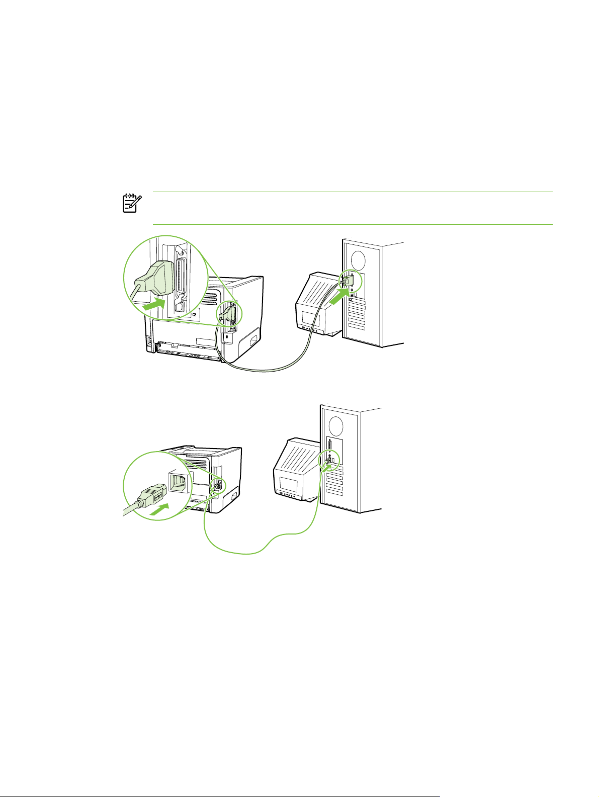
USB and parallel connections
1. Insert the software installation CD into the computer CD-ROM drive.
2. If the installation program does not start automatically, browse the CD contents and run the
SETUP.EXE file.
3. Follow the on-screen instructions.
NOTE: During the installation, there is a prompt to plug in the parallel or USB cable.
Refer to the figures below.
Figure 2-3 Parallel connection
Figure 2-4 USB connection
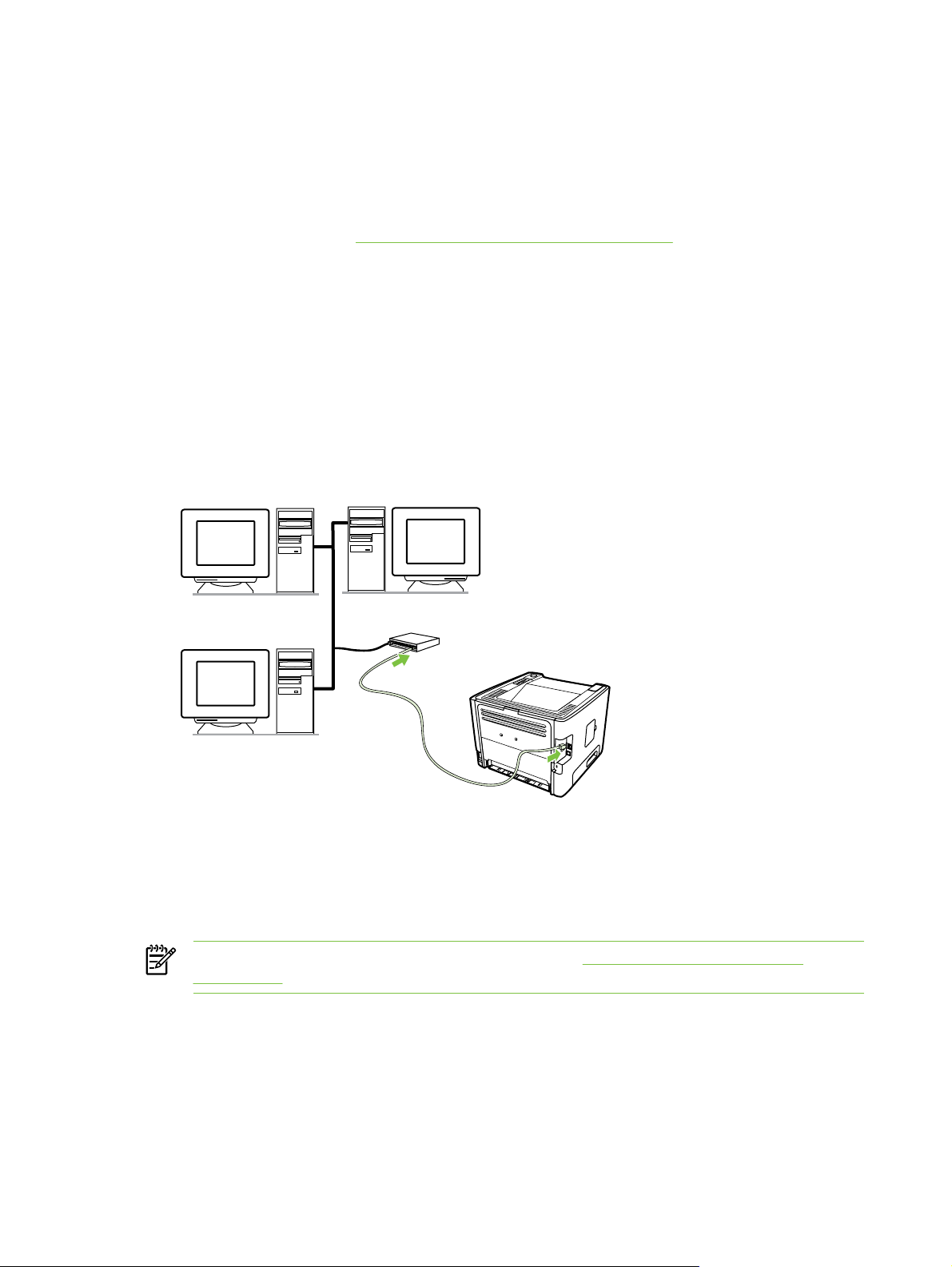
Network connections
The Network model can connect to a network through the HP internal networking port. External
network print servers are available for the non-network product model. The following list identifies
what is required to add networking to any non-network product model.
ENWW Printer connections 15
Page 26
10/100Base-TX Networking options
HP Jetdirect en3700
●
HP Jetdirect 175x
●
HP Jetdirect ew2400
●
To order the print server, see
10/100 networking print servers on page 227.
Connect the printer to the network
To connect a networking-equipped product, you need the following items:
Functional wired network
●
CAT-5 Ethernet cable
●
To connect the printer to your network, perform the following steps:
1. Connect the CAT-5 Ethernet cable to an available port on the Ethernet hub or router.
2. Connect the Ethernet cable to the Ethernet port on the back of the printer.
3. Verify that one of the network lights (10 or 100) is illuminated on the network port located on the
back of the printer.
4. Confirm that the product has been assigned an IP address by printing a Configuration page:
When the printer is in the Ready state, press and hold the Go button for 5 seconds when the
printer Ready light is on and no other jobs are printing.
NOTE: To resolve network connection problems, see Network-setup problem-solving
on page 157.
Install the printer software for the network printer
To use the printer on the network, install the printer software on a computer that is connected to the
network.
16 Chapter 2 Installation ENWW
Page 27

Software for Windows
Supported operating systems
The product comes with software for the following operating systems:
Windows® 98 SE (PCL 5e printer driver only)
●
Windows Me (PCL 5e printer driver only)
●
Windows NT 4.0 (PCL 5e printer driver only)
●
Windows 2000
●
Windows Server 2003 (32-bit)
●
Windows Server 2003 (64-bit) (PCL 5e printer driver only)
●
For more information about upgrading from Windows 2000 Server to Windows Server 2003,
using Windows Server 2003 Point and Print, or using Windows Server 2003 Terminal Services
and Printing, go to
● Windows XP (32-bit)
Windows XP (64-bit) (PCL 5e printer driver only)
●
Windows Vista (32-bit)
●
http://www.microsoft.com/.
Windows printer drivers
A printer driver is the software that provides access to printer features and provides the means for
the computer to print to the printer.
Windows driver types
This product features a host-based driver and a PCL 5e printer driver.
Install Windows software
To install printer software for Windows NT 4.0, Server 2003 (64-bit), Windows 98SE, Me, and XP (64-bit)
See the operating system documentation for instructions on installing a printer driver.
To install printer software for Windows 2000, XP (32-bit), Server 2003 (32-bit), and Vista (32-bit)
Insert the software CD that came with the printer into the computer CD-ROM drive. Follow the onscreen installation instructions.
NOTE: If the Welcome screen does not open, click Start on the Windows task bar and then
click Run. Type Z:\setup (where Z is your CD drive letter), and click OK.
Configure the Windows printer driver
Use one of the following methods to open the Windows printer driver from your computer:
ENWW Software for Windows 17
Page 28

Operating system To change the settings for all
print jobs until the software
program is closed
To change the print job
default settings (for example,
turn on Print on Both Sides
by default)
To change the configuration
settings (for example, add a
tray or enable/disable Manual
duplexing)
Windows 98 SE,
Me, 2000, XP (32–
bit and 64–bit), and
Server 2003
1. On the File menu in the
software program, click
Print.
2. Select the name of the
printer, and then click
Properties or
Preferences.
The steps can vary; this
procedure is most common.
1. Click Start, click Settings,
and then click Printers or
Printers and Faxes.
2. Right-click the printer icon,
and then select Printing
Preferences.
1. Click Start, click Settings,
and then click Printers or
Printers and Faxes.
2. Right-click the printer icon,
and then select Properties.
3. Click the Device Settings
tab.
18 Chapter 2 Installation ENWW
Page 29

Software for Macintosh
Macintosh printer drivers
A printer driver is the software component that provides access to printer features and provides the
means for the computer to communicate with the printer.
Install the Macintosh printer driver
This section explains how to install the printing system software for Macintosh OS X v10.2.8, v10.3,
v10.4 and later.
NOTE: USB queues are created automatically when the printer is attached to the computer.
However, the queue will use a generic PPD if the installer has not been run before the USB
cable is connected. To change the queue PPD, open the Print Center or Printer Setup Utility,
select the correct printer queue, and then click Show Info to open the Printer Info dialog box.
In the pop-up menu, select Printer Model, and then, in the pop-up menu in which Generic is
selected, select the correct PPD for the printer.
Use the following procedure to install the Macintosh printer driver:
1. Insert the printer CD into the CD-ROM drive and run the installer.
2. Double-click the CD icon on the desktop
3. Double-click the Installer icon.
4. Follow the instructions on the computer screen.
5. Print a test page or a page from any software program to make sure that the printer software is
correctly installed.
If installation fails, reinstall the software. If this fails, see the Late-Breaking Information section of the
Install Notes. The Install Notes are located on the printer CD or at the support Web site. (See
HP Customer Care on page 233 for the Web address.)
Configure the Macintosh printer driver
Use one of the following methods to open the Macintosh printer driver from your computer:
Operating System To change the settings for all
print jobs until the software
program is closed
Macintosh OS X
v10.2.8, v10.3,
v10.4 and later
1. On the File menu, click
Print.
2. Change the settings that
you want on the various
pop-up menus.
To change the print job
default settings (for example,
turn on Print on Both Sides
by default)
1. On the File menu, click
Print.
2. Change the settings that
you want on the various
pop-up menus.
3. On the Presets pop-up
menu, click Save as and
type a name for the preset.
To change the configuration
settings (for example, add a
tray or enable/disable Manual
duplexing)
1. Open Printer Setup
Utility by selecting the
hard drive, clicking
Applications, clicking
Utilities, then double-
clicking Printer Setup
Utility.
2. Click the print queue.
ENWW Software for Macintosh 19
Page 30

Operating System To change the settings for all
print jobs until the software
program is closed
To change the print job
default settings (for example,
turn on Print on Both Sides
by default)
To change the configuration
settings (for example, add a
tray or enable/disable Manual
duplexing)
These settings are saved in the
Presets menu. To use the new
settings, you must select the
saved preset option every time
you open a program and print.
PostScript Printer Description files (PPDs)
PPDs, in combination with the HP postscript level 3 emulation driver, provide access to the printer
features and allow the computer to communicate with the printer. An installation program for the
PPDs is provided on the printer CD.
3. On the Printers menu,
click Show Info.
4. Click the Installable
Options menu.
20 Chapter 2 Installation ENWW
Page 31

Printer information pages
You can print the following information pages.
Demo page
The Demo page contains examples of text and graphics. To print a Demo page, do one of the
following:
Press the Go button when the printer Ready light is on and no other jobs are printing.
●
Select it from the Print Information Pages drop-down list on the Services tab in Printer
●
Preferences.
Configuration page
The Configuration page lists current settings and properties of the printer. It also contains a status
log report. To print a configuration page, do one of the following:
Press and hold the Go button for 5 seconds when the printer Ready light is on and no other jobs
●
are printing.
Select it from the Print Information Pages drop-down list on the Services tab in Printer
●
Preferences.
Supplies Status page
You can print the Supplies Status page by selecting it from the Print Information Pages drop-down
list on the Services tab in Printer Preferences. The Supplies Status page provides the following
information:
The estimated number of pages remaining on the print cartridge
●
The number of pages and print jobs that have been processed
●
Ordering and recycling information
●
ENWW Printer information pages 21
Page 32

22 Chapter 2 Installation ENWW
Page 33

3 Manage the printer
This chapter provides information on the following topics:
Embedded Web server (network model only)
●
ENWW 23
Page 34

Embedded Web server (network model only)
The embedded Web server allows you to view printer and network status and to manage printing
functions from your computer instead of from the printer control panel. Below are examples of what
you can do using the embedded Web server:
View device status information
●
Determine the remaining life on all supplies and order new ones
●
Set the size and type of media loaded in each tray
●
View and change tray configurations
●
View and change the printer default configuration settings
●
View and change network configuration
●
You do not need to install any software on the computer. You only need to use one of these
●
supported Web browsers:
Internet Explorer 6.0 (and later)
●
Netscape Navigator 7.0 (and later)
●
Firefox 1.0 (and later)
●
● Mozilla 1.6 (and later)
Opera 7.0 (and later)
●
Safari 1.2 (and later)
●
Konqueror 3.2 (and later)
●
The embedded Web server works when the printer is connected to an TCP/IP-based network. The
embedded Web server does not support IPX-based connections or direct USB connections.
NOTE: You do not have to have Internet access to open and use the embedded Web
server. However, if you click a link on any of the pages, you must have Internet access in
order to go to the site associated with the link.
Open the embedded Web server
To open the embedded Web server, type the IP address or hostname of the printer in the address
field of a supported Web browser. To find the IP address, print a Configuration page at the printer by
pressing and holding the Go button for 5 seconds when the Ready light is on and no other jobs are
printing.
TIP: After you open the URL, bookmark it so that you can return to it quickly in the future.
The embedded Web server has three tabs that contain settings and information about the printer: the
Information tab, the Settings tab, and the Networking tab.
24 Chapter 3 Manage the printer ENWW
Page 35

Information tab
The Status pages group consists of the following pages.
●
Device Status. This page displays the status of the printer and HP supplies.
●
Device Configuration. This page shows the information found on the printer Configuration page.
Supplies Status. This page shows the status of HP supplies and provides supplies part
●
numbers. To order new supplies, click Shop For Supplies in the upper-right part of the window.
Network Summary. This page shows the information found on the printer Network Summary
●
page.
Settings tab
This tab allows you to configure the printer from your computer. You can view and change the
settings for the printer's input tray as well as the default printer job settings. If this printer is
networked, always consult with the printer administrator before changing settings on this tab.
Networking tab
This tab allows the network administrator to control network-related settings for the printer when it is
connected to an IP-based network.
Links
Links are located in the upper-right part of the Status pages. You must have Internet access in order
to use any of these links. If you use a dial-up connection and did not connect when you first opened
the embedded Web server, you must connect before you can visit these Web sites. Connecting
might require that you close the embedded Web server and reopen it.
Shop For Supplies. Click this link to connect to the Sure Supply Web site and order genuine
●
HP supplies from HP or a reseller of your choice.
Support. Connects to the support site for the HP LaserJet P2014 Series printer. You can
●
search for help regarding general topics.
ENWW Embedded Web server (network model only) 25
Page 36

26 Chapter 3 Manage the printer ENWW
Page 37

4 Maintenance
Replace the print cartridge
●
Redistribute toner
●
Clean the printer
●
Clean the pickup roller (tray 1)
●
Replace the pickup roller (tray 1)
●
Clean the pickup roller (tray 2)
●
Replace the pickup roller (tray 2)
●
EconoMode
●
ENWW 27
Page 38

Replace the print cartridge
1. Press the print-cartridge-door button, and then remove the print cartridge from the printer. For
recycling information, see the inside of the print-cartridge box.
2. Remove the new print cartridge from the packaging.
3. Bend the tab on the left side of the cartridge to break it loose.
4. Pull the tab until all the tape is removed from the cartridge. Put the tab in the print-cartridge box
to return for recycling.
28 Chapter 4 Maintenance ENWW
Page 39

5. Gently rock the print cartridge from front to back to distribute the toner evenly inside the cartridge.
CAUTION: If toner gets on your clothing, wipe it off with a dry cloth and wash the
clothing in cold water. Hot water sets toner into the fabric.
6. Insert the print cartridge in the printer and close the print-cartridge door.
CAUTION: If toner gets on your clothing, wipe it off with a dry cloth and wash the
clothing in cold water. Hot water sets toner into the fabric.
ENWW Replace the print cartridge 29
Page 40

Redistribute toner
When toner is low, faded or light areas appear on the printed page. You might be able to temporarily
improve print quality by redistributing the toner.
1. Press the print-cartridge-door button, and then remove the print cartridge from the printer.
2. To redistribute the toner, gently rock the print cartridge from front to back.
CAUTION: If toner gets on your clothing, wipe it off with a dry cloth and wash the
clothing in cold water. Hot water sets toner into the fabric.
3. Reinsert the print cartridge into the printer, and close the print cartridge door.
If the print is still light, install a new print cartridge. See Replace the print cartridge on page 28 for
instructions.
30 Chapter 4 Maintenance ENWW
Page 41

Clean the printer
Clean the outside of the printer with a clean, damp cloth when necessary.
CAUTION: Do not use ammonia-based cleaners on or around the printer.
During the printing process, paper, toner, and dust particles can accumulate inside the printer. Over
time, this buildup can cause print quality problems, such as toner specks or smearing, and paper
jams. To correct and prevent these types of problems, you can clean the print cartridge area and the
printer media path.
Clean the print-cartridge area
You do not need to clean the print-cartridge area often. However, cleaning this area can improve the
quality of your printed sheets.
WARNING! Before cleaning the printer, turn the printer off by unplugging the power cord,
and wait for the printer to cool.
1. Press the print-cartridge-door button, and then remove the print cartridge from the printer.
CAUTION: Do not touch the black sponge-transfer roller inside the printer. Doing so
can damage the printer.
CAUTION: To prevent damage, do not expose the print cartridge to light. Cover it with
a piece of paper.
ENWW Clean the printer 31
Page 42

2. With a dry, lint-free cloth, wipe any residue from the media-path area and the print-cartridge
cavity.
3. Replace the print cartridge, and close the print-cartridge door.
4. Plug the printer in to turn it back on.
5. Verify printer functionality by printing a demo page. To print a demo page, press the Go button
when the Ready light is on and no other jobs are printing.
32 Chapter 4 Maintenance ENWW
Page 43

Clean the printer media path
If you are experiencing toner specks or dots on the printouts, clean the printer media path. This
process uses a transparency to remove dust and toner from the media path. Do not use bond or
rough paper.
NOTE: For best results use a sheet of transparency. If you do not have any transparencies,
you can use copier grade media (70 to 90 g/m
1. Make sure that the printer is idle and the Ready light is on.
2. Load the transparency in tray 1.
3. Print a cleaning page. Open the printer Properties screen, select the Device Settings tab and
click Start.
NOTE: The cleaning process takes approximately 2 minutes. The cleaning page will stop
periodically during the cleaning process. Do not turn the printer off until the cleaning process
has finished. You might need to repeat the cleaning process several times to thoroughly clean
the printer.
2
(18 to 24 lb.)) with a smooth surface.
ENWW Clean the printer 33
Page 44

Clean the pickup roller (tray 1)
If you want to clean the pickup roller for tray 1, follow these instructions:
1. Unplug the power cord from the printer, and allow the printer to cool.
2. Press the print-cartridge-door button, and then remove the print cartridge from the printer.
CAUTION: Do not touch the black sponge-transfer roller inside the printer. Doing so
can damage the printer.
CAUTION: To prevent damage, do not expose the print cartridge to light. Cover it with
a piece of paper.
34 Chapter 4 Maintenance ENWW
Page 45

3. Grasping the pickup-roller cover with thumb and forefinger, squeeze the left side of the pickup-
roller cover to release the left retaining tab, and then slide the cover to the left and up.
CAUTION: Failure to slide the cover to the left when removing it can cause the right
retaining tab to break.
4. Press the two black retaining tabs outward until the pickup roller is released from its seat.
ENWW Clean the pickup roller (tray 1) 35
Page 46

5. Remove the pickup roller from the printer.
6. Dab a lint-free cloth in water, and scrub the roller.
NOTE: Do not touch the surface of the roller with bare fingers.
7. Using a dry, lint-free cloth, wipe the pickup roller to remove loosened dirt.
8. Allow the pickup roller to dry completely.
36 Chapter 4 Maintenance ENWW
Page 47

9. Line up the black retaining tabs in the printer with the grooves in the pickup roller, and then
press the pickup roller into the pickup roller seat until the retaining tabs click.
10. Grasping the pickup-roller cover with thumb and forefinger, insert the pickup-roller cover's right
retaining tab into the retaining slot.
ENWW Clean the pickup roller (tray 1) 37
Page 48

11. Squeeze the left side of the pickup-roller cover and insert the left retaining tab in the retaining
slot.
12. Reinstall the print cartridge, and close the print-cartridge door.
13. Plug the printer in to turn it back on.
14. Verify printer functionality by printing a demo page. To print a demo page, press the Go button
when the Ready light is on and no other jobs are printing.
38 Chapter 4 Maintenance ENWW
Page 49

Replace the pickup roller (tray 1)
1. Unplug the power cord from the printer, and allow the printer to cool.
2. Press the print-cartridge-door button, and then remove the print cartridge from the printer.
CAUTION: Do not touch the black sponge-transfer roller inside the printer. Doing so
can damage the printer.
CAUTION: To prevent damage, do not expose the print cartridge to light. Cover it with
a piece of paper.
ENWW Replace the pickup roller (tray 1) 39
Page 50

3. Grasping the pickup-roller cover with thumb and forefinger, squeeze the left side of the pickup-
roller cover to release the left retaining tab, and then slide the cover to the left and up.
CAUTION: Failure to slide the cover to the left when removing it can cause the right
retaining tab to break.
4. Press the two black retaining tabs outward until the pickup roller is released from its seat.
40 Chapter 4 Maintenance ENWW
Page 51

5. Remove the old pickup roller from the printer.
6. Line up the black retaining tabs in the printer with the grooves in the new pickup roller, and then
press the pickup roller into the pickup-roller seat until the retaining tabs click.
CAUTION: Do not touch the pickup-roller pad.
ENWW Replace the pickup roller (tray 1) 41
Page 52

7. Grasping the pickup-roller cover with thumb and forefinger, insert the pickup-roller cover's right
retaining tab into the retaining slot.
8. Squeeze the left side of the pickup-roller cover and insert the left retaining tab in the retaining
slot.
42 Chapter 4 Maintenance ENWW
Page 53

9. Reinstall the print cartridge, and close the print-cartridge door.
10. Plug the printer in to turn it back on.
ENWW Replace the pickup roller (tray 1) 43
Page 54

Clean the pickup roller (tray 2)
If you want to clean the pickup roller for tray 2, follow these instructions:
1. Unplug the power cord from the printer, and allow the printer to cool.
2. Press the print-cartridge-door button, and then remove the print cartridge from the printer.
CAUTION: Do not touch the black sponge-transfer roller inside the printer. Doing so
can damage the printer.
CAUTION: To prevent damage, do not expose the print cartridge to light. Cover it with
a piece of paper.
44 Chapter 4 Maintenance ENWW
Page 55

3. Remove tray 2.
4. Place the printer on the work surface with the front of the printer facing up.
ENWW Clean the pickup roller (tray 2) 45
Page 56

5. Pull the white tabs outward, and rotate the tabs up.
6. Slide the right tab to the right, and leave the tab in this position throughout the procedure.
46 Chapter 4 Maintenance ENWW
Page 57

7. Slide the pickup roller assembly to the left, and remove the left end cap.
8. Remove the pickup roller.
ENWW Clean the pickup roller (tray 2) 47
Page 58

9. Dab a lint-free cloth in water, and scrub the roller.
NOTE: Do not touch the surface of the roller with bare fingers.
10. Using a dry, lint-free cloth, wipe the pickup roller to remove loosened dirt.
11. Allow the pickup roller to dry completely.
12. Insert the left side of the pickup roller into the left slot (1), and insert the right side (the side that
has the notches in the shaft) into the right slot (2).
48 Chapter 4 Maintenance ENWW
Page 59

13. Place the end cap over the shaft on the left side, push the end cap to the right, and rotate the
tab downward into position.
14. Rotate the shaft until the notches engage and the shaft clicks into place.
15. Push the right tab to the left, and rotate the tab downward into position.
16. Place the printer on the work surface with the top of the printer facing up.
17. Reinstall the print cartridge, and close the print-cartridge door.
ENWW Clean the pickup roller (tray 2) 49
Page 60

18. Plug the printer in to turn it back on.
19. Verify printer functionality by printing a demo page. To print a demo page, press the Go button
when the Ready light is on and no other jobs are printing.
50 Chapter 4 Maintenance ENWW
Page 61

Replace the pickup roller (tray 2)
1. Unplug the power cord from the printer, and allow the printer to cool.
2. Press the print-cartridge-door button, and then remove the print cartridge from the printer.
CAUTION: After removing the print cartridge, only handle it on the ends.
3. Remove tray 2.
ENWW Replace the pickup roller (tray 2) 51
Page 62

4. Place the printer on the work surface with the front of the printer facing up.
5. Pull the white tabs outward, and rotate the tabs up.
52 Chapter 4 Maintenance ENWW
Page 63

6. Slide the right tab to the right, and leave the tab in this position throughout the procedure.
7. Slide the pickup roller assembly to the left, and remove the left end cap.
ENWW Replace the pickup roller (tray 2) 53
Page 64

8. Remove the old pickup roller.
CAUTION: Do not touch the pickup-roller pad.
9. Insert the left side of the new pickup roller into the left slot (1), and insert the right side (the side
that has the notches in the shaft) into the right slot (2).
54 Chapter 4 Maintenance ENWW
Page 65

10. Place the end cap over the shaft on the left side, push the end cap to the right, and rotate the
tab downward into position.
11. Rotate the shaft until the notches engage and the shaft clicks into place.
12. Push the right tab to the left, and rotate the tab downward into position.
13. Place the printer on the work surface with the top of the printer facing up.
14. Reinstall the print cartridge, and close the print-cartridge door.
ENWW Replace the pickup roller (tray 2) 55
Page 66

15. Plug the printer in to turn it back on.
56 Chapter 4 Maintenance ENWW
Page 67

EconoMode
EconoMode is a feature that allows the printer to use less toner per page. Selecting this option may
extend the life of the print cartridge and reduce your cost per page. However, it will also reduce print
quality. The printed image is lighter, but it is adequate for printing drafts or proofs.
HP does not recommend the full-time use of EconoMode. If EconoMode is used full-time, it is
possible that the toner supply will outlast the mechanical parts in the print cartridge. If print quality
begins to degrade under these circumstances, you must install a new print cartridge, even if toner
supply remains in the cartridge.
1. To use EconoMode, open the printer Properties (or Printing Preferences in Windows 2000
and XP). See
printer driver on page 19 for instructions.
2. On the Paper/Quality tab or the Finishing tab (the Paper Type/Quality tab for some Mac
drivers), select the EconoMode checkbox.
NOTE: Not all printer features are available in all drivers or operating systems. See the
printer Properties (driver) online Help for information about availability of features for that driver.
Configure the Windows printer driver on page 17 or Configure the Macintosh
ENWW EconoMode 57
Page 68

58 Chapter 4 Maintenance ENWW
Page 69

5 Theory of operation
Introduction
●
Internal components
●
Timing
●
Engine control system
●
Laser/scanner system
●
Pickup/feed/delivery system
●
Image-formation system
●
ENWW 59
Page 70

Introduction
This chapter presents an overview of the relationships between major components in the printer, and
includes a detailed discussion of the image-formation system. The following systems are discussed:
Engine control system
●
Laser/scanner system
●
Pickup/feed/delivery system
●
Image-formation system
●
Figure 5-1 Block diagram on page 60 illustrates the relationships among the four systems.
Figure 5-1 Block diagram
60 Chapter 5 Theory of operation ENWW
Page 71

Internal components
Figure 5-2 Cross-section of printer on page 61 highlights the major internal components.
Figure 5-2 Cross-section of printer
1 Top output bin delivery roller
2 Fuser film
3 Laser/scanner
4 Primary charging roller
5 Developer roller
6 Print cartridge
7 Feed roller
8 Multipurpose pickup roller
9 Multipurpose separation pad
10 Separation pad
ENWW Internal components 61
Page 72

11 Pickup roller
12 Registration roller
13 Registration shutter
14 Transfer roller
15 Photosensitive drum
16 Pressure roller
17 Rear output bin delivery roller
62 Chapter 5 Theory of operation ENWW
Page 73

Timing
Sequence of operation
Operation sequences are controlled by the microprocessor on the DC controller.
Table 5-1 Sequence
of operation on page 63 describes engine operations for each period of a print operation.
Table 5-1 Sequence of operation
Name Timing Purpose
WAIT From power-on until the end of the main motor
STBY (standby) From the end of the WAIT or LSTR period until
INTR (initial
rotation)
PRINT From the end of the INTR period until the primary
LSTR (last
rotation)
initial drive
either a print command is sent from the formatter or
the power is turned off.
From the time of the print command until the pickup
solenoid is turned on.
high-voltage is turned off.
From the end of the PRINT period (when highvoltage is turned off) until the main motor stops
rotating.
Detects presence of a print cartridge. Clears
potential from the drum surface and cleans the
transfer roller.
Prepares the printer to receive print commands
Prepares the photosensitive drum for printing.
Forms the image on the photosensitive drum and
transfers the toner image to the media.
Delivers the last page of a print job.
After LSTR, the printer either returns to STBY or, if
another print command was sent from the
formatter, enters INTR.
Power-on sequence
Table 5-2 Power-on sequence
Step Acti on
1 Power-on
2 CPU initialization
3 Video interface communication start
4 Check sensors for residual media
5 Main motor initial drive
6 Fuser heater initial drive. The fuser heater reaches a surface temperature of 100°C.
7 Laser/scanner motor initial drive
8 High-voltage control
Detect presence of a print cartridge
Clean the transfer roller after the primary charging ac bias is turned on
9 Failure/abnormality check: detect laser/scanner failure, fuser failure, and open covers
10 Communication with the memory tag
ENWW Timing 63
Page 74

Engine control system
The engine control system coordinates all printer functions, according to commands sent from the
formatter. It drives the laser/scanner system, the image-formation system, and the pickup/feed/
delivery system.
The engine control system contains the following components:
DC controller
●
High-voltage PCA
●
Figure 5-3 Engine control system
64 Chapter 5 Theory of operation ENWW
Page 75

Engine controller PCB
Main motor
Fixing unit
AC input
Fan
Transfer
charging roller
Pressure roller
Cartridge
Memory tag
Fixing control
circuit
Low-voltage power
supply circuit
Fan motor drive
circuit
Reset Circuit
High-voltage
power supply
circuit
Memory tag circuit
IC201
CPU
Solenoids
Sensors
Duplex driver
PCB
(Duplex model
only)
Option
Scanner motor
Video controller PCB
Figure 5-4 Engine control system circuit diagram
Laser driver
BD sensor
ENWW Engine control system 65
Page 76

Laser/scanner system
The laser/scanner system receives video signals from the dc controller and the formatter and
converts the signals into latent images on the photosensitive drum.
Figure 5-5 Laser/scanner system
66 Chapter 5 Theory of operation ENWW
Page 77

Pickup/feed/delivery system
The pickup/feed/delivery system consists of several types of feed rollers and sensors. The dc
controller uses two motors and two solenoids to drive the rollers. Three media-detection sensors
detect media as it passes through the printer. If media does not reach or pass each sensor within a
specified time period, the dc controller determines that a jam has occurred and alerts the formatter.
The following components are identified in
M1, main motor
●
SL1, tray 2 pickup solenoid
●
SL2, tray 1 pickup solenoid
●
PS911, width-detection sensor
●
PS912, top-of-page sensor
●
PS913, width-detection sensor
●
PS914, tray 2 media sensor
●
PS915, fuser delivery sensor
●
Figure 5-6 Pickup/feed/delivery system on page 68:
ENWW Pickup/feed/delivery system 67
Page 78

Figure 5-6 Pickup/feed/delivery system
68 Chapter 5 Theory of operation ENWW
Page 79

Image-formation system
Laser printing requires the interaction of several different technologies, including electronics, optics,
and electrophotographics, to provide a printed page. Each process functions independently and must
be coordinated with the other printer processes. Image formation consists of the following five
processes:
electrostatic latent-image formation
●
developing
●
transfer
●
fusing
●
drum cleaning
●
The five processes contain eight steps.
Figure 5-7 Image-formation system
Step 1: Primary charging
DC and AC biases are applied to the primary charging roller, which transfers a uniform negative
potential to the photosensitive drum.
Figure 5-8 Primary charging
Step 2: Laser beam exposure
ENWW Image-formation system 69
Page 80

The laser beam scans the photosensitive drum to neutralize negative charges on parts of the drum.
An electrostatic latent image is formed on the drum where negative charges were neutralized.
Step 3: Developing
The developing cylinder comes in contact with the photosensitive drum to deposit toner onto the
electrostatic latent image.
NOTE: The charges on the exposed area of the drum are shown as positive in Figure 5-9
Developing on page 70. The charges are actually negative, but they are more positive than
the charges on the developing cylinder.
Figure 5-9 Developing
Toner acquires a negative charge through friction from the developing cylinder and the blade. When
the negatively charged toner comes in contact with the drum, the toner adheres to the electrostatic
latent image. The image on the drum becomes visible because of the toner.
Step 4: Transfer
The transfer charging roller, to which a dc positive bias is applied, imparts a positive charge on the
print media. When the print media comes in contact with the photosensitive drum, the toner is
transferred to the print media.
70 Chapter 5 Theory of operation ENWW
Page 81

Figure 5-10 Transfer
Step 5: Separation
The elasticity of the print media causes its separation from the photosensitive drum. A static charge
eliminator aids separation by weakening any electrostatic adhesion.
Figure 5-11 Separation
Step 6: Fusing
The dc negative bias applied to the fusing film strengthens the holding force of the toner on the print
media and prevents the toner from scattering.
ENWW Image-formation system 71
Page 82

Figure 5-12 Fusing
Step 7: Drum cleaning
The cleaning blade scrapes the residual toner off the photosensitive drum and deposits it into the
waste toner case.
Figure 5-13 Drum cleaning
72 Chapter 5 Theory of operation ENWW
Page 83

6 Removal and replacement
Introduction
●
Before performing service
●
Covers
●
Control panel
●
Formatter
●
Laser/scanner
●
Memory-tag-reader assembly
●
Fuser
●
Interlock assembly
●
ECU
●
Main motor
●
Pickup and feed assemblies
●
Main gear assembly/tray 2 pickup solenoid
●
Print-cartridge door
●
ENWW 73
Page 84

Introduction
This chapter documents removal and replacement of field replaceable units (FRUs) only.
Removal and replacement strategy
Replace parts in the reverse order of their removal. Directions for difficult or critical replacement
procedures are included.
WARNING! The sheet-metal edges of the product can be sharp. Use caution when working
on the product.
NOTE: Note the length, diameter, color, type, and location of each screw. Be sure to return
each screw to its original location during reassembly.
Incorrectly routed or loose wire harnesses can interfere with other internal components and
can become damaged or broken. Frayed or pinched harness wires can be difficult to locate.
When replacing wire harnesses, always use the provided wire loops, lance points, or wireharness guides.
Electrostatic discharge
CAUTION: The product contains parts that are sensitive to electrostatic discharge (ESD).
Always service the product at an ESD-protected workstation, or use an ESD mat.
Watch for the ESD symbol to identify the parts that are sensitive to ESD. Protect these parts by using
an ESD wrist strap and by placing ESD-sensitive parts into protective ESD pouches.
Required tools
The following tools are needed to service this product:
#2 Phillips screwdriver with magnetic tip
●
Small flat-blade screwdriver
●
Small needle-nose pliers
●
ESD mat
●
Penlight
●
CAUTION: A pozidrive screwdriver can damage the screw heads on the product. Use a #2
Phillips screwdriver.
If you use a multispeed screwdriver, use a torque limiter.
74 Chapter 6 Removal and replacement ENWW
Page 85

Before performing service
Follow the pre-service procedures before you perform service.
Pre-service procedures
1. Remove all media from the product.
2. Place the product on an ESD mat. If an ESD mat or an ESD-protected workstation is not
available, discharge body static and ground the product chassis before servicing the product.
3. Remove the print cartridge.
4. Unplug the power cord and the interface cable.
5. Lift the printer off optional tray 3 (if tray 3 is installed).
Parts removal order
Use the following diagram to determine which parts must be removed before removing other parts.
ENWW Before performing service 75
Page 86

Covers
Left-side cover
1. Open the print-cartridge door.
2. At the back of the printer, use a flat-blade screwdriver to release two tabs (1).
Figure 6-1 Removing the left-side cover (1 of 2)
3. Lift the cover away from the printer.
Right-side cover
1. Open the print-cartridge door.
2. Remove tray 2.
76 Chapter 6 Removal and replacement ENWW
Page 87

3. At the front of the printer, pop the front edge of the right-side cover over the two retaining tabs.
4. Lift the cover away from the printer.
Back cover
1. Remove tray 2.
2. Remove the left-side cover and the right-side cover.
Figure 6-2 Removing the right-side cover
ENWW Covers 77
Page 88

3. Remove four screws (1).
4. Tip the printer so that it rests on its front.
5. Release the tab (2) at the back of the printer on the right side.
6. Lift the cover straight up and away from the printer.
Top cover
1. Remove the left-side cover, the right-side cover, and the back cover.
Figure 6-3 Removing the back cover (1 of 2)
78 Chapter 6 Removal and replacement ENWW
Page 89

2. Remove two screws (1) at the back of the printer.
Figure 6-4 Removing the top cover (1 of 4)
ENWW Covers 79
Page 90

3. Remove one screw (1) on the left side of the printer, and remove one screw (2) on the right side
of the printer.
Figure 6-5 Removing the top cover (2 of 4)
80 Chapter 6 Removal and replacement ENWW
Page 91

4. Release the control-panel cable (1) on the left side of the printer.
Figure 6-6 Removing the top cover (3 of 4)
ENWW Covers 81
Page 92

5. Lift the top cover off the printer.
Figure 6-7 Removing the top cover (4 of 4)
82 Chapter 6 Removal and replacement ENWW
Page 93

Control panel
1. Remove all covers.
2. On the bottom of the top cover, remove two screws (1).
Figure 6-8 Removing the control panel (1 of 2)
ENWW Control panel 83
Page 94

3. Remove the control-panel wires from the wire guides.
Figure 6-9 Removing the control panel (2 of 2)
84 Chapter 6 Removal and replacement ENWW
Page 95

Formatter
1. Remove the left-side cover.
2. Disconnect one cable (1) at the top of the formatter.
3. Disconnect one flat, flexible cable (2) at the top of the formatter.
4. Disconnect one flat, flexible cable (3) at the bottom of the formatter.
5. Disconnect one cable (4) at the bottom of the formatter.
6. Remove four screws (5).
CAUTION: Do not fold flat, flexible cables. Also, do not straighten pre-folds in flat,
flexible cables.
Figure 6-10 Removing the formatter
7. Remove the formatter.
ENWW Formatter 85
Page 96

Laser/scanner
1. Remove all covers.
2. Disconnect one flat, flexible cable (1) from the laser/scanner PCA.
3. Disconnect one cable (2) from the top of the laser/scanner.
4. Unthread all cables (3) from the laser/scanner cable guides.
NOTE: Examine the cable routing as you unthread the cables.
5. Remove four screws (4).
Figure 6-11 Removing the laser/scanner
6. Lift the laser/scanner out of the printer.
NOTE: Examine the shutter switch as you lift the laser/scanner out of the printer.
86 Chapter 6 Removal and replacement ENWW
Page 97

Memory-tag-reader assembly
1. Remove all covers.
2. Remove the fan from the printer chassis.
3. Remove one cable (1) from the top of the memory-tag-reader cover.
4. Disconnect one cable (2) from the formatter.
Figure 6-12 Removing the memory-tag-reader assembly (1 of 2)
ENWW Memory-tag-reader assembly 87
Page 98

5. Remove one screw (1).
Figure 6-13 Removing the memory-tag-reader assembly (2 of 2)
6. Lift the back of the memory-tag-reader assembly slightly, and then slide the assembly toward
the back of the printer to release it from the laser/scanner plate.
88 Chapter 6 Removal and replacement ENWW
Page 99

Fuser
Fan
Several parts must be removed before you can remove the fuser. The following parts are included in
this section about removing the fuser:
Fan
●
● face-down gears
Fuser
●
1. Remove all covers.
2. Disconnect the fan cable (1) at the ECU.
Figure 6-14 Removing the fan (1 of 2)
3. Unthread the fan wires from the retaining clips.
4. Remove two screws (1).
ENWW Fuser 89
Page 100

5. Unhook the fan clip (2) and then lift the fan off the printer.
Fuser
Figure 6-15 Removing the fan (2 of 2)
1. Remove all covers.
2. Remove the fan.
3. Remove the face-down gears.
4. Remove the formatter.
5. On the right side of the printer, press the tabs on two gears (1) to release the gears, and then
slide the gears off the shafts.
90 Chapter 6 Removal and replacement ENWW
 Loading...