

Page 1
hp LaserJet 3300mfp
series
service
Page 2

Page 3

hp LaserJet 3300mfp series
Service
Page 4

Copyright Information
©
2002 Hewlett-Packard
Company
All Rights Reserved.
Reproduction, adaptations, or
translation without prior written
permission is prohibited except
as allowed under copyright
laws.
Part number C9124-90948
Second edition, February 2002
Warranty
The information contained in
this document is subject to
change without notice.
Hewlett-Packard makes no
warranty of any kind with
respect to thi s informati o n .
HEWLETT-PACKARD
SPECIFICALLY DISCLAIMS
THE IMPLIED WARRANTY OF
MERCHANTABILITY AND
FITNESS FOR A PARTICULAR
PURPOSE.
Hewlett-Packard shall not be
liable for any direct, indirect,
incidental, consequential, or
other damage alleged in
connection with the furnishing or
use of this information.
NOTICE TO U.S.
GOVERNMENT USERS:
RESTRICTED RIGHTS
COMMERCIAL COMPUTER
SOFTWARE: “Use, duplication,
or disclosure by the
Government is subject to
restrictions as set forth in
subparagraph (c) (1)(ii) of the
Rights in Technical Data Clause
at DFARS 52.227-7013.”
Trademark Credits
Microsoft, Windows, and MSDOS are U.S. registered
trademarks of Microsoft
Corporation.
TrueType is a U.S. trademark of
Apple Computer, Inc.
All other products mentioned
herein may be trademarks of
their respective companies.
Safety Information
WARNING!
Potential Shock Hazard
Always follow basic safety
precautions when using this
product to reduce risk of injury
from fire or electric shock.
1 Read and understand all
instructions in the user
guide.
2 Observe all warnings and
instructions marked on the
product.
3 Use only a grounded
electrical outlet when
connecting the
HP LaserJet 3300mfp
product to a power source.
If you don’t know whether
the outlet is grounded,
check with a qualified
electrician.
4 Do not touch the contacts
on the end of any of the
sockets on the
HP LaserJet 3300mfp.
Replace damaged cords
immediately.
5 Unplug this product from
wall outlets before
cleaning.
6 Do not install or use this
product near water or
when you are wet.
7 Install the product securely
on a stable surface.
8 Install the product in a
protected location where
no one can step on or trip
over the power cord and
the power cord will not be
damaged.
9 If the product does not
operate normally, see the
online user guide.
10 Refer all servicing
questions to qualified
personnel.
Information regarding FCC
Class B, Parts 15 and 68
requirements can be found in
the user guide.:
Hewlett-Packard Company
11311 Chinden Boulevard
Boise, Idaho 83714 U.S.A.
Page 5

Contents
1 Product information
Chapter contents. . . . . . . . . . . . . . . . . . . . . . . . . . . . . . . . . . . . . . . . . . . . . . . . . . . . 15
Introduction . . . . . . . . . . . . . . . . . . . . . . . . . . . . . . . . . . . . . . . . . . . . . . . . . . . . . . . . 16
Overview of product . . . . . . . . . . . . . . . . . . . . . . . . . . . . . . . . . . . . . . . . . . . . . . . . . 16
Front and side view. . . . . . . . . . . . . . . . . . . . . . . . . . . . . . . . . . . . . . . . . . . . . . . 16
Back and side view. . . . . . . . . . . . . . . . . . . . . . . . . . . . . . . . . . . . . . . . . . . . . . . 17
Hardware description . . . . . . . . . . . . . . . . . . . . . . . . . . . . . . . . . . . . . . . . . . . . . 18
Firmware description . . . . . . . . . . . . . . . . . . . . . . . . . . . . . . . . . . . . . . . . . . . . . 19
Product Specifications. . . . . . . . . . . . . . . . . . . . . . . . . . . . . . . . . . . . . . . . . . . . . . . . 19
Model and serial numbers. . . . . . . . . . . . . . . . . . . . . . . . . . . . . . . . . . . . . . . . . . . . . 22
Warranty statement. . . . . . . . . . . . . . . . . . . . . . . . . . . . . . . . . . . . . . . . . . . . . . . . . . 23
Extended warranty . . . . . . . . . . . . . . . . . . . . . . . . . . . . . . . . . . . . . . . . . . . . . . . 24
Print cartridge information . . . . . . . . . . . . . . . . . . . . . . . . . . . . . . . . . . . . . . . . . . . . 25
Refilled print cartridges . . . . . . . . . . . . . . . . . . . . . . . . . . . . . . . . . . . . . . . . . . . 25
Recycling print cartridges . . . . . . . . . . . . . . . . . . . . . . . . . . . . . . . . . . . . . . . . . . 25
FCC Part 68 Requirements (US). . . . . . . . . . . . . . . . . . . . . . . . . . . . . . . . . . . . . . . . 26
Telephone Consumer Protection Act (US) . . . . . . . . . . . . . . . . . . . . . . . . . . . . . 27
IC CS-03 requirements. . . . . . . . . . . . . . . . . . . . . . . . . . . . . . . . . . . . . . . . . . . . 27
Regulatory information for EU countries. . . . . . . . . . . . . . . . . . . . . . . . . . . . . . . 28
2 Operation
Chapter contents. . . . . . . . . . . . . . . . . . . . . . . . . . . . . . . . . . . . . . . . . . . . . . . . . . . . 29
Operating environment . . . . . . . . . . . . . . . . . . . . . . . . . . . . . . . . . . . . . . . . . . . . . . . 30
Identifying the control panel components . . . . . . . . . . . . . . . . . . . . . . . . . . . . . . . . . 31
Fax controls . . . . . . . . . . . . . . . . . . . . . . . . . . . . . . . . . . . . . . . . . . . . . . . . . . . . 31
To send a fax to one recipient . . . . . . . . . . . . . . . . . . . . . . . . . . . . . . . . . . . . . . 31
To receive faxes when you hear fax tones . . . . . . . . . . . . . . . . . . . . . . . . . . . . . 32
Alphanumeric buttons. . . . . . . . . . . . . . . . . . . . . . . . . . . . . . . . . . . . . . . . . . . . . 33
Menu and cancel controls. . . . . . . . . . . . . . . . . . . . . . . . . . . . . . . . . . . . . . . . . . 34
Copy, scan, and start controls . . . . . . . . . . . . . . . . . . . . . . . . . . . . . . . . . . . . . . 34
Control panel menu structure . . . . . . . . . . . . . . . . . . . . . . . . . . . . . . . . . . . . . . . . . . 35
To print the control panel menu structure. . . . . . . . . . . . . . . . . . . . . . . . . . . . . . 35
To use the control panel keys. . . . . . . . . . . . . . . . . . . . . . . . . . . . . . . . . . . . . . . 35
Control panel error messages. . . . . . . . . . . . . . . . . . . . . . . . . . . . . . . . . . . . . . . . . . 38
Product media specifications. . . . . . . . . . . . . . . . . . . . . . . . . . . . . . . . . . . . . . . . . . . 45
Supported media sizes (printer) . . . . . . . . . . . . . . . . . . . . . . . . . . . . . . . . . . . . . 45
Guidelines for using media . . . . . . . . . . . . . . . . . . . . . . . . . . . . . . . . . . . . . . . . . . . . 46
Paper and Transparencies . . . . . . . . . . . . . . . . . . . . . . . . . . . . . . . . . . . . . . . . . 46
Common media problems table . . . . . . . . . . . . . . . . . . . . . . . . . . . . . . . . . . . . . 46
Labels . . . . . . . . . . . . . . . . . . . . . . . . . . . . . . . . . . . . . . . . . . . . . . . . . . . . . . . . . 47
EN Contents 3
Page 6

Envelopes. . . . . . . . . . . . . . . . . . . . . . . . . . . . . . . . . . . . . . . . . . . . . . . . . . . . . . 47
Card stock and heavy media . . . . . . . . . . . . . . . . . . . . . . . . . . . . . . . . . . . . . . . 48
Loading media. . . . . . . . . . . . . . . . . . . . . . . . . . . . . . . . . . . . . . . . . . . . . . . . . . . . . . 49
Loading media to print . . . . . . . . . . . . . . . . . . . . . . . . . . . . . . . . . . . . . . . . . . . . 49
Selecting originals for the ADF . . . . . . . . . . . . . . . . . . . . . . . . . . . . . . . . . . . . . . . . . 50
Media information for the flatbed. . . . . . . . . . . . . . . . . . . . . . . . . . . . . . . . . . . . . . . . 51
Loading originals to copy or scan . . . . . . . . . . . . . . . . . . . . . . . . . . . . . . . . . . . . . . . 51
To load originals onto the flatbed scanner . . . . . . . . . . . . . . . . . . . . . . . . . . . . . 51
To load originals into the ADF input tray. . . . . . . . . . . . . . . . . . . . . . . . . . . . . . . 52
Printer output paths . . . . . . . . . . . . . . . . . . . . . . . . . . . . . . . . . . . . . . . . . . . . . . 54
3 Maintenance
Chapter contents. . . . . . . . . . . . . . . . . . . . . . . . . . . . . . . . . . . . . . . . . . . . . . . . . . . . 55
Life expectancies of parts that wear . . . . . . . . . . . . . . . . . . . . . . . . . . . . . . . . . . . . . 56
Scanner calibration . . . . . . . . . . . . . . . . . . . . . . . . . . . . . . . . . . . . . . . . . . . . . . . . . . 56
Cleaning the product . . . . . . . . . . . . . . . . . . . . . . . . . . . . . . . . . . . . . . . . . . . . . . . . . 57
Cleaning the exterior. . . . . . . . . . . . . . . . . . . . . . . . . . . . . . . . . . . . . . . . . . . . . . 57
Cleaning the glass . . . . . . . . . . . . . . . . . . . . . . . . . . . . . . . . . . . . . . . . . . . . . . . 57
Cleaning the lid backing . . . . . . . . . . . . . . . . . . . . . . . . . . . . . . . . . . . . . . . . . . . 58
Cleaning the print path . . . . . . . . . . . . . . . . . . . . . . . . . . . . . . . . . . . . . . . . . . . . 59
Cleaning the print cartridge area . . . . . . . . . . . . . . . . . . . . . . . . . . . . . . . . . . . . 60
Cleaning the printer pickup roller . . . . . . . . . . . . . . . . . . . . . . . . . . . . . . . . . . . . 61
Cleaning the printer separation pad . . . . . . . . . . . . . . . . . . . . . . . . . . . . . . . . . . 62
User-replaceable parts . . . . . . . . . . . . . . . . . . . . . . . . . . . . . . . . . . . . . . . . . . . . . . . 63
Replacing the printer pickup roller . . . . . . . . . . . . . . . . . . . . . . . . . . . . . . . . . . . 63
Replacing the printer separation pad . . . . . . . . . . . . . . . . . . . . . . . . . . . . . . . . . 65
Installing a new ADF . . . . . . . . . . . . . . . . . . . . . . . . . . . . . . . . . . . . . . . . . . . . . . . . . 67
To install a new or replacement ADF . . . . . . . . . . . . . . . . . . . . . . . . . . . . . . . . . 67
Changing an ADF pick roller assembly. . . . . . . . . . . . . . . . . . . . . . . . . . . . . . . . . . . 69
Removing and replacing the control panel bezel . . . . . . . . . . . . . . . . . . . . . . . . . . . 71
4 Operational overview
Chapter contents. . . . . . . . . . . . . . . . . . . . . . . . . . . . . . . . . . . . . . . . . . . . . . . . . . . . 73
Basic functions . . . . . . . . . . . . . . . . . . . . . . . . . . . . . . . . . . . . . . . . . . . . . . . . . . . . . 74
Formatter system . . . . . . . . . . . . . . . . . . . . . . . . . . . . . . . . . . . . . . . . . . . . . . . . . . . 76
Central processing unit . . . . . . . . . . . . . . . . . . . . . . . . . . . . . . . . . . . . . . . . . . . 76
Line Interface Unit (LIU) . . . . . . . . . . . . . . . . . . . . . . . . . . . . . . . . . . . . . . . . . . . 76
Scanner formatter PCA. . . . . . . . . . . . . . . . . . . . . . . . . . . . . . . . . . . . . . . . . . . . 76
Flash memory or ROM . . . . . . . . . . . . . . . . . . . . . . . . . . . . . . . . . . . . . . . . . . . . 77
Standard Boot Process. . . . . . . . . . . . . . . . . . . . . . . . . . . . . . . . . . . . . . . . . . . . 77
RAM . . . . . . . . . . . . . . . . . . . . . . . . . . . . . . . . . . . . . . . . . . . . . . . . . . . . . . . . . . 78
Parallel interface or Universal Serial Bus interface. . . . . . . . . . . . . . . . . . . . . . . 78
Control panel . . . . . . . . . . . . . . . . . . . . . . . . . . . . . . . . . . . . . . . . . . . . . . . . . . . 78
Draft mode . . . . . . . . . . . . . . . . . . . . . . . . . . . . . . . . . . . . . . . . . . . . . . . . . . . . . 78
MEt . . . . . . . . . . . . . . . . . . . . . . . . . . . . . . . . . . . . . . . . . . . . . . . . . . . . . . . . . . . 78
Enhanced I/O . . . . . . . . . . . . . . . . . . . . . . . . . . . . . . . . . . . . . . . . . . . . . . . . . . . 79
4 Contents EN
Page 7

PJL overview . . . . . . . . . . . . . . . . . . . . . . . . . . . . . . . . . . . . . . . . . . . . . . . . . . . 79
Scanner and ADF functions and operation . . . . . . . . . . . . . . . . . . . . . . . . . . . . . . . . 80
Scanner Functions . . . . . . . . . . . . . . . . . . . . . . . . . . . . . . . . . . . . . . . . . . . . . . . 80
Scanner Operation . . . . . . . . . . . . . . . . . . . . . . . . . . . . . . . . . . . . . . . . . . . . . . . 81
ADF Operation . . . . . . . . . . . . . . . . . . . . . . . . . . . . . . . . . . . . . . . . . . . . . . . . . . 81
ADF paper path and ADF sensors . . . . . . . . . . . . . . . . . . . . . . . . . . . . . . . . . . . 82
ADF Jam Detection. . . . . . . . . . . . . . . . . . . . . . . . . . . . . . . . . . . . . . . . . . . . . . . 83
Printer functions and operation . . . . . . . . . . . . . . . . . . . . . . . . . . . . . . . . . . . . . . . . . 84
Engine control unit/power system. . . . . . . . . . . . . . . . . . . . . . . . . . . . . . . . . . . . 85
Image formation system . . . . . . . . . . . . . . . . . . . . . . . . . . . . . . . . . . . . . . . . . . . 91
Printer paper-feed system . . . . . . . . . . . . . . . . . . . . . . . . . . . . . . . . . . . . . . . . . 94
Jam detection . . . . . . . . . . . . . . . . . . . . . . . . . . . . . . . . . . . . . . . . . . . . . . . . . . . 96
Basic sequence of operation (formatter-to-printer). . . . . . . . . . . . . . . . . . . . . . . 98
LIU (fax) functions and operation . . . . . . . . . . . . . . . . . . . . . . . . . . . . . . . . . . . . . . 100
PSTN operation . . . . . . . . . . . . . . . . . . . . . . . . . . . . . . . . . . . . . . . . . . . . . . . . 100
The fax subsystem . . . . . . . . . . . . . . . . . . . . . . . . . . . . . . . . . . . . . . . . . . . . . . 100
Formatter in the fax subsystem . . . . . . . . . . . . . . . . . . . . . . . . . . . . . . . . . . . . 101
LIU in the fax subsystem . . . . . . . . . . . . . . . . . . . . . . . . . . . . . . . . . . . . . . . . . 101
Fax page storage in flash memory . . . . . . . . . . . . . . . . . . . . . . . . . . . . . . . . . . 105
5 Removal and replacement
Chapter contents. . . . . . . . . . . . . . . . . . . . . . . . . . . . . . . . . . . . . . . . . . . . . . . . . . . 107
Removal and replacement strategy. . . . . . . . . . . . . . . . . . . . . . . . . . . . . . . . . . . . . 109
Required tools. . . . . . . . . . . . . . . . . . . . . . . . . . . . . . . . . . . . . . . . . . . . . . . . . . 109
Before performing service. . . . . . . . . . . . . . . . . . . . . . . . . . . . . . . . . . . . . . . . . 110
Print cartridge . . . . . . . . . . . . . . . . . . . . . . . . . . . . . . . . . . . . . . . . . . . . . . . . . . 110
Parts removal order . . . . . . . . . . . . . . . . . . . . . . . . . . . . . . . . . . . . . . . . . . . . . 111
Separation of scanner from printer . . . . . . . . . . . . . . . . . . . . . . . . . . . . . . . . . . . . . 113
Right side cover . . . . . . . . . . . . . . . . . . . . . . . . . . . . . . . . . . . . . . . . . . . . . . . . 113
Scanner side covers . . . . . . . . . . . . . . . . . . . . . . . . . . . . . . . . . . . . . . . . . . . . . 115
Scanner assemblies . . . . . . . . . . . . . . . . . . . . . . . . . . . . . . . . . . . . . . . . . . . . . . . . 119
Flat lid or ADF assembly. . . . . . . . . . . . . . . . . . . . . . . . . . . . . . . . . . . . . . . . . . 119
The ADF pick roller assembly. . . . . . . . . . . . . . . . . . . . . . . . . . . . . . . . . . . . . . 120
ADF document feed guide . . . . . . . . . . . . . . . . . . . . . . . . . . . . . . . . . . . . . . . . 122
ADF separation pad . . . . . . . . . . . . . . . . . . . . . . . . . . . . . . . . . . . . . . . . . . . . . 123
Control panel bezel. . . . . . . . . . . . . . . . . . . . . . . . . . . . . . . . . . . . . . . . . . . . . . 124
Control panel . . . . . . . . . . . . . . . . . . . . . . . . . . . . . . . . . . . . . . . . . . . . . . . . . . 125
Control panel chassis . . . . . . . . . . . . . . . . . . . . . . . . . . . . . . . . . . . . . . . . . . . . 126
Scanner formatter. . . . . . . . . . . . . . . . . . . . . . . . . . . . . . . . . . . . . . . . . . . . . . . 127
ADF scanner glass . . . . . . . . . . . . . . . . . . . . . . . . . . . . . . . . . . . . . . . . . . . . . . 128
Printer covers . . . . . . . . . . . . . . . . . . . . . . . . . . . . . . . . . . . . . . . . . . . . . . . . . . . . . 129
Left side door . . . . . . . . . . . . . . . . . . . . . . . . . . . . . . . . . . . . . . . . . . . . . . . . . . 129
Back cover . . . . . . . . . . . . . . . . . . . . . . . . . . . . . . . . . . . . . . . . . . . . . . . . . . . . 130
Printer top cover . . . . . . . . . . . . . . . . . . . . . . . . . . . . . . . . . . . . . . . . . . . . . . . . 132
Front cover assembly . . . . . . . . . . . . . . . . . . . . . . . . . . . . . . . . . . . . . . . . . . . . 133
Printer assemblies. . . . . . . . . . . . . . . . . . . . . . . . . . . . . . . . . . . . . . . . . . . . . . . . . . 137
EN Contents 5
Page 8

Transfer roller . . . . . . . . . . . . . . . . . . . . . . . . . . . . . . . . . . . . . . . . . . . . . . . . . . 140
Line Interface Unit (LIU) . . . . . . . . . . . . . . . . . . . . . . . . . . . . . . . . . . . . . . . . . . 141
Formatter . . . . . . . . . . . . . . . . . . . . . . . . . . . . . . . . . . . . . . . . . . . . . . . . . . . . . 142
Fuser assembly . . . . . . . . . . . . . . . . . . . . . . . . . . . . . . . . . . . . . . . . . . . . . . . . 144
Output rollers . . . . . . . . . . . . . . . . . . . . . . . . . . . . . . . . . . . . . . . . . . . . . . . . . . 148
Motor. . . . . . . . . . . . . . . . . . . . . . . . . . . . . . . . . . . . . . . . . . . . . . . . . . . . . . . . . 150
Solenoid . . . . . . . . . . . . . . . . . . . . . . . . . . . . . . . . . . . . . . . . . . . . . . . . . . . . . . 151
Fan assembly . . . . . . . . . . . . . . . . . . . . . . . . . . . . . . . . . . . . . . . . . . . . . . . . . . 153
Pickup assembly. . . . . . . . . . . . . . . . . . . . . . . . . . . . . . . . . . . . . . . . . . . . . . . . 155
Paper lift-plate assembly and pickup roller shaft . . . . . . . . . . . . . . . . . . . . . . . 157
Right plate assembly . . . . . . . . . . . . . . . . . . . . . . . . . . . . . . . . . . . . . . . . . . . . 160
Left plate assembly. . . . . . . . . . . . . . . . . . . . . . . . . . . . . . . . . . . . . . . . . . . . . . 162
Bottom assemblies . . . . . . . . . . . . . . . . . . . . . . . . . . . . . . . . . . . . . . . . . . . . . . . . . 163
Left bottom frame support. . . . . . . . . . . . . . . . . . . . . . . . . . . . . . . . . . . . . . . . . 163
ECU fuses and ECU pan . . . . . . . . . . . . . . . . . . . . . . . . . . . . . . . . . . . . . . . . . 164
Paper-feed assembly . . . . . . . . . . . . . . . . . . . . . . . . . . . . . . . . . . . . . . . . . . . . 168
6 Troubleshooting
Chapter contents. . . . . . . . . . . . . . . . . . . . . . . . . . . . . . . . . . . . . . . . . . . . . . . . . . . 173
Basic troubleshooting . . . . . . . . . . . . . . . . . . . . . . . . . . . . . . . . . . . . . . . . . . . . . . . 174
Errors. . . . . . . . . . . . . . . . . . . . . . . . . . . . . . . . . . . . . . . . . . . . . . . . . . . . . . . . . . . . 178
Control panel messages . . . . . . . . . . . . . . . . . . . . . . . . . . . . . . . . . . . . . . . . . 178
Critical error messages. . . . . . . . . . . . . . . . . . . . . . . . . . . . . . . . . . . . . . . . . . . 185
Checking the print cartridge . . . . . . . . . . . . . . . . . . . . . . . . . . . . . . . . . . . . . . . 187
Solving image-quality problems . . . . . . . . . . . . . . . . . . . . . . . . . . . . . . . . . . . . 188
Solving paper-feed problems . . . . . . . . . . . . . . . . . . . . . . . . . . . . . . . . . . . . . . . . . 197
Solving print paper-feed problems . . . . . . . . . . . . . . . . . . . . . . . . . . . . . . . . . . 197
Solving scanner (copier) paper-feed problems . . . . . . . . . . . . . . . . . . . . . . . . 199
Functional checks . . . . . . . . . . . . . . . . . . . . . . . . . . . . . . . . . . . . . . . . . . . . . . . . . . 200
Engine test . . . . . . . . . . . . . . . . . . . . . . . . . . . . . . . . . . . . . . . . . . . . . . . . . . . . 200
Half self-test functional check . . . . . . . . . . . . . . . . . . . . . . . . . . . . . . . . . . . . . 201
Drum rotation functional check . . . . . . . . . . . . . . . . . . . . . . . . . . . . . . . . . . . . 202
Heating element check . . . . . . . . . . . . . . . . . . . . . . . . . . . . . . . . . . . . . . . . . . 203
High-voltage power supply check. . . . . . . . . . . . . . . . . . . . . . . . . . . . . . . . . . . 204
Paper path check . . . . . . . . . . . . . . . . . . . . . . . . . . . . . . . . . . . . . . . . . . . . . . . 206
Updating or recovering the firmware code . . . . . . . . . . . . . . . . . . . . . . . . . . . . . . . 207
Firmware update via flash executable . . . . . . . . . . . . . . . . . . . . . . . . . . . . . . . 207
Firmware recovery DIMM . . . . . . . . . . . . . . . . . . . . . . . . . . . . . . . . . . . . . . . . . 207
Troubleshooting tools . . . . . . . . . . . . . . . . . . . . . . . . . . . . . . . . . . . . . . . . . . . . . . . 209
Internal reports . . . . . . . . . . . . . . . . . . . . . . . . . . . . . . . . . . . . . . . . . . . . . . . . . 209
Printing all fax reports at once . . . . . . . . . . . . . . . . . . . . . . . . . . . . . . . . . . . . . 209
T.30 protocol trace . . . . . . . . . . . . . . . . . . . . . . . . . . . . . . . . . . . . . . . . . . . . . . 210
Service mode functions. . . . . . . . . . . . . . . . . . . . . . . . . . . . . . . . . . . . . . . . . . . . . . 229
Secondary service menu . . . . . . . . . . . . . . . . . . . . . . . . . . . . . . . . . . . . . . . . . 229
Developer’s menu. . . . . . . . . . . . . . . . . . . . . . . . . . . . . . . . . . . . . . . . . . . . . . . 230
NVRAM init . . . . . . . . . . . . . . . . . . . . . . . . . . . . . . . . . . . . . . . . . . . . . . . . . . . . 233
6 Contents EN
Page 9

PJL software commands . . . . . . . . . . . . . . . . . . . . . . . . . . . . . . . . . . . . . . . . . 233
Repetitive image defect ruler . . . . . . . . . . . . . . . . . . . . . . . . . . . . . . . . . . . . . . . . . 236
Main wiring . . . . . . . . . . . . . . . . . . . . . . . . . . . . . . . . . . . . . . . . . . . . . . . . . . . . . . . 237
Locations of connectors . . . . . . . . . . . . . . . . . . . . . . . . . . . . . . . . . . . . . . . . . . . . . 239
Locations of connectors and switches. . . . . . . . . . . . . . . . . . . . . . . . . . . . . . . . . . . 240
7 Parts and diagrams
Chapter contents. . . . . . . . . . . . . . . . . . . . . . . . . . . . . . . . . . . . . . . . . . . . . . . . . . . 241
Ordering parts and supplies . . . . . . . . . . . . . . . . . . . . . . . . . . . . . . . . . . . . . . . . . . 242
Parts . . . . . . . . . . . . . . . . . . . . . . . . . . . . . . . . . . . . . . . . . . . . . . . . . . . . . . . . . 242
Related documentation and software . . . . . . . . . . . . . . . . . . . . . . . . . . . . . . . . 242
Parts that wear . . . . . . . . . . . . . . . . . . . . . . . . . . . . . . . . . . . . . . . . . . . . . . . . . 242
Accessories . . . . . . . . . . . . . . . . . . . . . . . . . . . . . . . . . . . . . . . . . . . . . . . . . . . 243
Common hardware . . . . . . . . . . . . . . . . . . . . . . . . . . . . . . . . . . . . . . . . . . . . . . . . . 244
How to use the parts lists and diagrams . . . . . . . . . . . . . . . . . . . . . . . . . . . . . . . . . 245
Scanner assemblies . . . . . . . . . . . . . . . . . . . . . . . . . . . . . . . . . . . . . . . . . . . . . . . . 246
Scanner and ADF . . . . . . . . . . . . . . . . . . . . . . . . . . . . . . . . . . . . . . . . . . . . . . . 246
ADF rollers and separation pad . . . . . . . . . . . . . . . . . . . . . . . . . . . . . . . . . . . . 248
Control panel assembly . . . . . . . . . . . . . . . . . . . . . . . . . . . . . . . . . . . . . . . . . . 249
Printer assemblies. . . . . . . . . . . . . . . . . . . . . . . . . . . . . . . . . . . . . . . . . . . . . . . . . . 252
Printer covers . . . . . . . . . . . . . . . . . . . . . . . . . . . . . . . . . . . . . . . . . . . . . . . . . . 252
Paper tray . . . . . . . . . . . . . . . . . . . . . . . . . . . . . . . . . . . . . . . . . . . . . . . . . . . . 253
Internal assemblies . . . . . . . . . . . . . . . . . . . . . . . . . . . . . . . . . . . . . . . . . . . . . . . . . 254
Internal components (1 of 2). . . . . . . . . . . . . . . . . . . . . . . . . . . . . . . . . . . . . . . 254
Internal components (2 of 2). . . . . . . . . . . . . . . . . . . . . . . . . . . . . . . . . . . . . . . 256
Electrical components. . . . . . . . . . . . . . . . . . . . . . . . . . . . . . . . . . . . . . . . . . . . 258
Paper pickup assembly (1 of 2) . . . . . . . . . . . . . . . . . . . . . . . . . . . . . . . . . . . . 260
Paper pickup assembly (2 of 2) . . . . . . . . . . . . . . . . . . . . . . . . . . . . . . . . . . . . 262
Fuser assembly . . . . . . . . . . . . . . . . . . . . . . . . . . . . . . . . . . . . . . . . . . . . . . . . 264
Alphabetical parts list . . . . . . . . . . . . . . . . . . . . . . . . . . . . . . . . . . . . . . . . . . . . . . . 266
Numerical parts list . . . . . . . . . . . . . . . . . . . . . . . . . . . . . . . . . . . . . . . . . . . . . . . . . 271
Index
EN Contents 7
Page 10

8 Contents EN
Page 11

Figures
Figure 1. Front and side view . . . . . . . . . . . . . . . . . . . . . . . . . . . . . . . . . . . . . . . 16
Figure 2. Back and side view. . . . . . . . . . . . . . . . . . . . . . . . . . . . . . . . . . . . . . . . 17
Figure 3. Model and serial number labels . . . . . . . . . . . . . . . . . . . . . . . . . . . . . . 22
Figure 4. Dimensions of product . . . . . . . . . . . . . . . . . . . . . . . . . . . . . . . . . . . . . 30
Figure 5. Fax controls . . . . . . . . . . . . . . . . . . . . . . . . . . . . . . . . . . . . . . . . . . . . . 31
Figure 6. Alphanumeric controls . . . . . . . . . . . . . . . . . . . . . . . . . . . . . . . . . . . . . 33
Figure 7. Menu and cancel buttons . . . . . . . . . . . . . . . . . . . . . . . . . . . . . . . . . . . 34
Figure 8. Copy, scan, and start controls . . . . . . . . . . . . . . . . . . . . . . . . . . . . . . . 34
Figure 9. Output bin and straight-through output path. . . . . . . . . . . . . . . . . . . . . 54
Figure 10. Product configuration . . . . . . . . . . . . . . . . . . . . . . . . . . . . . . . . . . . . . . 75
Figure 11. Optical diagram of scanner. . . . . . . . . . . . . . . . . . . . . . . . . . . . . . . . . . 80
Figure 12. Document scanner path . . . . . . . . . . . . . . . . . . . . . . . . . . . . . . . . . . . 82
Figure 13. Printer unit functional block diagram . . . . . . . . . . . . . . . . . . . . . . . . . . 84
Figure 14. ECU loads . . . . . . . . . . . . . . . . . . . . . . . . . . . . . . . . . . . . . . . . . . . . . . 86
Figure 15. Overview of laser/scanner operation . . . . . . . . . . . . . . . . . . . . . . . . . . 87
Figure 16. High-voltage power supply circuit. . . . . . . . . . . . . . . . . . . . . . . . . . . . . 90
Figure 17. Image formation block diagram . . . . . . . . . . . . . . . . . . . . . . . . . . . . . . 91
Figure 18. Printer paper path. . . . . . . . . . . . . . . . . . . . . . . . . . . . . . . . . . . . . . . . . 95
Figure 19. Solenoid, photosensors, and switches . . . . . . . . . . . . . . . . . . . . . . . . . 97
Figure 20. Printer timing diagram . . . . . . . . . . . . . . . . . . . . . . . . . . . . . . . . . . . . 99
Figure 21. Removing the print cartridge . . . . . . . . . . . . . . . . . . . . . . . . . . . . . . . 110
Figure 22. Removing the right side cover (1 of 3) . . . . . . . . . . . . . . . . . . . . . . . . 113
Figure 23. Removing the right side cover (2 of 3) . . . . . . . . . . . . . . . . . . . . . . . . 114
Figure 24. Removing the right side cover (3 of 3) . . . . . . . . . . . . . . . . . . . . . . . . 115
Figure 25. Removing the right scanner cover . . . . . . . . . . . . . . . . . . . . . . . . . . . 115
Figure 26. Removing the left scanner cover . . . . . . . . . . . . . . . . . . . . . . . . . . . . 116
Figure 27. Separating the scanner from the printer (1 of 4). . . . . . . . . . . . . . . . . 116
Figure 28. Separating the scanner from the printer (2 of 4). . . . . . . . . . . . . . . . . 117
Figure 29. Separating the scanner from the printer (3 of 4). . . . . . . . . . . . . . . . . 117
Figure 30. Separating the scanner from the printer (4 of 4). . . . . . . . . . . . . . . . . 118
Figure 31. Removing the ADF assembly. . . . . . . . . . . . . . . . . . . . . . . . . . . . . . . 119
Figure 32. Removing the document feed guide (1 of 2) . . . . . . . . . . . . . . . . . . . 122
Figure 33. Removing the document feed guide (2 of 2) . . . . . . . . . . . . . . . . . . . 122
Figure 34. Removing the ADF separation pad . . . . . . . . . . . . . . . . . . . . . . . . . . 123
Figure 35. Removing the control panel bezel . . . . . . . . . . . . . . . . . . . . . . . . . . . 124
Figure 36. Reinstalling the control panel bezel (1 of 2) . . . . . . . . . . . . . . . . . . . . 124
Figure 37. Reinstalling the control panel bezel (2 of 2) . . . . . . . . . . . . . . . . . . . . 124
Figure 38. Removing the control panel . . . . . . . . . . . . . . . . . . . . . . . . . . . . . . . . 125
Figure 39. Removing the control panel chassis (1 of 2) . . . . . . . . . . . . . . . . . . . 126
Figure 40. Removing the control panel chassis (2 of 2) . . . . . . . . . . . . . . . . . . . 126
Figure 41. Removing the scanner formatter . . . . . . . . . . . . . . . . . . . . . . . . . . . . 127
EN Figures 9
Page 12

Figure 42. Removing the ADF scanner glass . . . . . . . . . . . . . . . . . . . . . . . . . . . 128
Figure 43. Installing the ADF scanner glass . . . . . . . . . . . . . . . . . . . . . . . . . . . . 128
Figure 44. Removing the left side door . . . . . . . . . . . . . . . . . . . . . . . . . . . . . . . . 129
Figure 45. Removing the back cover (1 of 2). . . . . . . . . . . . . . . . . . . . . . . . . . . . 130
Figure 46. Removing the back cover (2 of 2). . . . . . . . . . . . . . . . . . . . . . . . . . . . 131
Figure 47. Removing the printer top cover . . . . . . . . . . . . . . . . . . . . . . . . . . . . . 132
Figure 48. Removing the print cartridge door (1 of 2) . . . . . . . . . . . . . . . . . . . . . 133
Figure 49. Removing the print cartridge door (2 of 2) . . . . . . . . . . . . . . . . . . . . . 134
Figure 50. Removing the front cover (1 of 2). . . . . . . . . . . . . . . . . . . . . . . . . . . . 135
Figure 51. Front cover removed . . . . . . . . . . . . . . . . . . . . . . . . . . . . . . . . . . . . . 135
Figure 52. Removing the front cover (2 of 2). . . . . . . . . . . . . . . . . . . . . . . . . . . . 136
Figure 53. Removing the front guide assembly (1 of 3). . . . . . . . . . . . . . . . . . . . 137
Figure 54. Removing the front guide assembly (2 of 3). . . . . . . . . . . . . . . . . . . . 138
Figure 55. Removing the front guide assembly (3 of 3). . . . . . . . . . . . . . . . . . . . 138
Figure 56. Removing the left and right support covers . . . . . . . . . . . . . . . . . . . . 139
Figure 57. Removing the transfer roller. . . . . . . . . . . . . . . . . . . . . . . . . . . . . . . . 140
Figure 58. Removing the LIU. . . . . . . . . . . . . . . . . . . . . . . . . . . . . . . . . . . . . . . . 141
Figure 59. Removing the formatter (1 of 3) . . . . . . . . . . . . . . . . . . . . . . . . . . . . . 142
Figure 60. Removing the formatter (2 of 3) . . . . . . . . . . . . . . . . . . . . . . . . . . . . . 143
Figure 61. Removing the formatter (3 of 3) . . . . . . . . . . . . . . . . . . . . . . . . . . . . . 143
Figure 62. Removing the fuser assembly (1 of 4) . . . . . . . . . . . . . . . . . . . . . . . . 144
Figure 63. Removing the fuser assembly (2 of 4) . . . . . . . . . . . . . . . . . . . . . . . . 145
Figure 64. Removing the fuser assembly (3 of 4) . . . . . . . . . . . . . . . . . . . . . . . . 146
Figure 65. Removing the fuser assembly (4 of 4) . . . . . . . . . . . . . . . . . . . . . . . . 147
Figure 66. Removing the output rollers (1 of 2) . . . . . . . . . . . . . . . . . . . . . . . . . . 148
Figure 67. Removing the output rollers (2 of 2) . . . . . . . . . . . . . . . . . . . . . . . . . . 149
Figure 68. Removing the motor . . . . . . . . . . . . . . . . . . . . . . . . . . . . . . . . . . . . . . 150
Figure 69. Removing the solenoid (1 of 2). . . . . . . . . . . . . . . . . . . . . . . . . . . . . . 151
Figure 70. Removing the solenoid (2 of 2). . . . . . . . . . . . . . . . . . . . . . . . . . . . . . 152
Figure 71. Removing the fan (1 of 2). . . . . . . . . . . . . . . . . . . . . . . . . . . . . . . . . . 153
Figure 72. Removing the fan (2 of 2). . . . . . . . . . . . . . . . . . . . . . . . . . . . . . . . . . 154
Figure 73. Removing the pickup assembly plate (1 of 3). . . . . . . . . . . . . . . . . . . 155
Figure 74. Removing the pickup assembly plate (2 of 3). . . . . . . . . . . . . . . . . . . 156
Figure 75. Removing the pickup assembly plate (3 of 3). . . . . . . . . . . . . . . . . . . 156
Figure 76. Removing the paper lift-plate assembly (1 of 3). . . . . . . . . . . . . . . . . 157
Figure 77. Removing the paper lift-plate assembly (2 of 3). . . . . . . . . . . . . . . . . 158
Figure 78. Removing the paper lift-plate assembly (3 of 3). . . . . . . . . . . . . . . . . 158
Figure 79. Paper lift-plate springs . . . . . . . . . . . . . . . . . . . . . . . . . . . . . . . . . . . . 159
Figure 80. Removing the pickup roller shaft . . . . . . . . . . . . . . . . . . . . . . . . . . . . 159
Figure 81. Removing the right plate assembly (1 of 2) . . . . . . . . . . . . . . . . . . . . 160
Figure 82. Removing the right plate assembly (2 of 2) . . . . . . . . . . . . . . . . . . . . 161
Figure 83. Removing the left plate assembly. . . . . . . . . . . . . . . . . . . . . . . . . . . . 162
Figure 84. Removing the left bottom frame support . . . . . . . . . . . . . . . . . . . . . . 163
Figure 85. Removing the ECU pan (1 of 5) . . . . . . . . . . . . . . . . . . . . . . . . . . . . . 164
Figure 86. Removing the ECU pan (2 of 5) . . . . . . . . . . . . . . . . . . . . . . . . . . . . . 165
Figure 87. Removing the ECU pan (3 of 5) . . . . . . . . . . . . . . . . . . . . . . . . . . . . . 165
Figure 88. Removing the ECU pan (4 of 5) . . . . . . . . . . . . . . . . . . . . . . . . . . . . . 166
10 Figures EN
Page 13

Figure 89. Removing the ECU pan (5 of 5) . . . . . . . . . . . . . . . . . . . . . . . . . . . . . 167
Figure 90. Removing the paper-feed assembly (1 of 4) . . . . . . . . . . . . . . . . . . . 168
Figure 91. Removing the paper-feed assembly (2 of 4) . . . . . . . . . . . . . . . . . . . 169
Figure 92. Removing the paper-feed mechanism (3 of 4) . . . . . . . . . . . . . . . . . . 170
Figure 93. Removing the paper-feed mechanism (4 of 4) . . . . . . . . . . . . . . . . . . 171
Figure 94. Engine test switch. . . . . . . . . . . . . . . . . . . . . . . . . . . . . . . . . . . . . . . . 200
Figure 95. Locating connectors for the heating element check. . . . . . . . . . . . . . 203
Figure 96. Print cartridge high-voltage connection points (right side) . . . . . . . . . 204
Figure 97. Print cartridge high-voltage connection points (left side) . . . . . . . . . . 204
Figure 98. High-voltage connector assembly (right side) . . . . . . . . . . . . . . . . . . 205
Figure 99. High-voltage connector assembly (left side). . . . . . . . . . . . . . . . . . . . 205
Figure 100. Overriding SW301 . . . . . . . . . . . . . . . . . . . . . . . . . . . . . . . . . . . . . . . 206
Figure 101. Using the firmware recovery DIMM . . . . . . . . . . . . . . . . . . . . . . . . . . 208
Figure 102. Example of a T.30 trace of a successfully sent fax . . . . . . . . . . . . . . 227
Figure 103. Example of a T.30 trace of a successfully received fax . . . . . . . . . . . 228
Figure 104. NVRAM PJL factory variables . . . . . . . . . . . . . . . . . . . . . . . . . . . . . . 234
Figure 105. Repetitive image defect ruler . . . . . . . . . . . . . . . . . . . . . . . . . . . . . . . 236
Figure 106. Main wiring (1 of 2). . . . . . . . . . . . . . . . . . . . . . . . . . . . . . . . . . . . . . . 237
Figure 107. Main wiring (2 of 2). . . . . . . . . . . . . . . . . . . . . . . . . . . . . . . . . . . . . . . 238
Figure 108. Locations of printer connectors . . . . . . . . . . . . . . . . . . . . . . . . . . . . . 239
Figure 109. Locations of connectors and switches . . . . . . . . . . . . . . . . . . . . . . . . 240
Figure 110. Scanner covers and ADF . . . . . . . . . . . . . . . . . . . . . . . . . . . . . . . . . . 246
Figure 111. ADF rollers and separation pad . . . . . . . . . . . . . . . . . . . . . . . . . . . . . 248
Figure 112. Control panel assembly . . . . . . . . . . . . . . . . . . . . . . . . . . . . . . . . . . . 249
Figure 113. Printer covers . . . . . . . . . . . . . . . . . . . . . . . . . . . . . . . . . . . . . . . . . . . 252
Figure 114. Paper tray. . . . . . . . . . . . . . . . . . . . . . . . . . . . . . . . . . . . . . . . . . . . . . 253
Figure 115. Internal components (1 of 2). . . . . . . . . . . . . . . . . . . . . . . . . . . . . . . . 254
Figure 116. Internal components (2 of 2). . . . . . . . . . . . . . . . . . . . . . . . . . . . . . . . 256
Figure 117. Electrical components . . . . . . . . . . . . . . . . . . . . . . . . . . . . . . . . . . . . 258
Figure 118. Paper pickup assembly (1 of 2) . . . . . . . . . . . . . . . . . . . . . . . . . . . . . 260
Figure 119. Paper pickup assembly (2 of 2) . . . . . . . . . . . . . . . . . . . . . . . . . . . . . 262
Figure 120. Fuser assembly . . . . . . . . . . . . . . . . . . . . . . . . . . . . . . . . . . . . . . . . . 264
EN Figures 11
Page 14

12 Figures EN
Page 15

Tables
Table 1. Physical specifications . . . . . . . . . . . . . . . . . . . . . . . . . . . . . . . . . . . . . 19
Table 2. Environmental specifications . . . . . . . . . . . . . . . . . . . . . . . . . . . . . . . 19
Table 3. Performance of HP LaserJet 3300mfp series. . . . . . . . . . . . . . . . . . . . 19
Table 4. Performance of ADF for copying/scanning. . . . . . . . . . . . . . . . . . . . . . 20
Table 5. Electrical specifications . . . . . . . . . . . . . . . . . . . . . . . . . . . . . . . . . . . . 20
Table 6. Acoustic emissions (HP LaserJet 3300mfp series) . . . . . . . . . . . . . . . 20
Table 7. Skew specifications . . . . . . . . . . . . . . . . . . . . . . . . . . . . . . . . . . . . . . . 21
Table 8. HP LaserJet 3330 fax specifications . . . . . . . . . . . . . . . . . . . . . . . . . . 21
Table 9. Control panel menu structure. . . . . . . . . . . . . . . . . . . . . . . . . . . . . . . . 36
Table 10. Control panel error messages . . . . . . . . . . . . . . . . . . . . . . . . . . . . . . . 38
Table 11. Media types . . . . . . . . . . . . . . . . . . . . . . . . . . . . . . . . . . . . . . . . . . . . . 45
Table 12. Life expectancies of parts that wear. . . . . . . . . . . . . . . . . . . . . . . . . . . 56
Table 13. Product startup messages . . . . . . . . . . . . . . . . . . . . . . . . . . . . . . . . . . 77
Table 14. Basic sequence of operation . . . . . . . . . . . . . . . . . . . . . . . . . . . . . . . . 98
Table 15. Basic troubleshooting . . . . . . . . . . . . . . . . . . . . . . . . . . . . . . . . . . . . 174
Table 16. Alert and warning messages . . . . . . . . . . . . . . . . . . . . . . . . . . . . . . . 178
Table 17. Critical error messages. . . . . . . . . . . . . . . . . . . . . . . . . . . . . . . . . . . . 185
Table 18. Solving print image-quality problems . . . . . . . . . . . . . . . . . . . . . . . . . 188
Table 19. Solving scanning (copying) image-quality problems . . . . . . . . . . . . . 194
Table 20. Solving print paper-feed problems . . . . . . . . . . . . . . . . . . . . . . . . . . . 197
Table 21. Solving scanner paper-feed problems . . . . . . . . . . . . . . . . . . . . . . . . 199
Table 22. Fax receive error codes . . . . . . . . . . . . . . . . . . . . . . . . . . . . . . . . . . . 211
Table 23. Fax send error codes . . . . . . . . . . . . . . . . . . . . . . . . . . . . . . . . . . . . . 216
Table 24. Fax phase sequence . . . . . . . . . . . . . . . . . . . . . . . . . . . . . . . . . . . . . 223
Table 25. Appropriate responses . . . . . . . . . . . . . . . . . . . . . . . . . . . . . . . . . . . . 224
Table 26. Fax abbreviations . . . . . . . . . . . . . . . . . . . . . . . . . . . . . . . . . . . . . . . . 225
Table 27. Country/region codes . . . . . . . . . . . . . . . . . . . . . . . . . . . . . . . . . . . . 231
Table 28. Switch functions . . . . . . . . . . . . . . . . . . . . . . . . . . . . . . . . . . . . . . . . . 240
Table 29. Technical support websites . . . . . . . . . . . . . . . . . . . . . . . . . . . . . . . . 242
Table 30. Accessories . . . . . . . . . . . . . . . . . . . . . . . . . . . . . . . . . . . . . . . . . . . . 243
Table 31. Common fasteners . . . . . . . . . . . . . . . . . . . . . . . . . . . . . . . . . . . . . . . 244
Table 32. Scanner and ADF. . . . . . . . . . . . . . . . . . . . . . . . . . . . . . . . . . . . . . . . 247
Table 33. ADF rollers and separation pad . . . . . . . . . . . . . . . . . . . . . . . . . . . . . 248
Table 34. Control panel assembly . . . . . . . . . . . . . . . . . . . . . . . . . . . . . . . . . . . 249
Table 35. Printer covers . . . . . . . . . . . . . . . . . . . . . . . . . . . . . . . . . . . . . . . . . . . 252
Table 36. Paper tray. . . . . . . . . . . . . . . . . . . . . . . . . . . . . . . . . . . . . . . . . . . . . . 253
Table 37. Internal components (1 of 2). . . . . . . . . . . . . . . . . . . . . . . . . . . . . . . . 255
Table 38. Internal components (2 of 2). . . . . . . . . . . . . . . . . . . . . . . . . . . . . . . . 257
Table 39. Electrical components . . . . . . . . . . . . . . . . . . . . . . . . . . . . . . . . . . . . 259
Table 40. Paper pickup assembly (1 of 2) . . . . . . . . . . . . . . . . . . . . . . . . . . . . . 261
Table 41. Paper pickup assembly (2 of 2) . . . . . . . . . . . . . . . . . . . . . . . . . . . . . 263
EN Tables 13
Page 16

Table 42. Fuser assembly . . . . . . . . . . . . . . . . . . . . . . . . . . . . . . . . . . . . . . . . . 265
Table 43. Alphabetical parts list . . . . . . . . . . . . . . . . . . . . . . . . . . . . . . . . . . . . . 266
Table 44. Numerical parts list. . . . . . . . . . . . . . . . . . . . . . . . . . . . . . . . . . . . . . . 271
14 Chapter - Tables EN
Page 17

1Product information
Chapter contents
Introduction . . . . . . . . . . . . . . . . . . . . . . . . . . . . . . . . . . . . . . . 16
Overview of product . . . . . . . . . . . . . . . . . . . . . . . . . . . . . . . . . 16
Front and side view . . . . . . . . . . . . . . . . . . . . . . . . . . . . . . 16
Back and side view . . . . . . . . . . . . . . . . . . . . . . . . . . . . . . 17
Hardware description. . . . . . . . . . . . . . . . . . . . . . . . . . . . . 18
Firmware description . . . . . . . . . . . . . . . . . . . . . . . . . . . . 19
Product Specifications . . . . . . . . . . . . . . . . . . . . . . . . . . . . . . . 19
Model and serial numbers . . . . . . . . . . . . . . . . . . . . . . . . . . . . 22
Warranty statement . . . . . . . . . . . . . . . . . . . . . . . . . . . . . . . . . 23
Extended warranty. . . . . . . . . . . . . . . . . . . . . . . . . . . . . . . 24
Print cartridge information . . . . . . . . . . . . . . . . . . . . . . . . . . . . 25
Refilled print cartridges . . . . . . . . . . . . . . . . . . . . . . . . . . 25
Recycling print cartridges . . . . . . . . . . . . . . . . . . . . . . . . . 26
FCC Part 68 Requirements (US) . . . . . . . . . . . . . . . . . . . . . . . 26
Telephone Consumer Protection Act (US) . . . . . . . . . . . . 27
IC CS-03 requirements . . . . . . . . . . . . . . . . . . . . . . . . . . . 27
Regulatory information for EU countries . . . . . . . . . . . . . . 28
EN Chapter contents 15
Page 18
Introduction
The HP LaserJet 3300mfp series is designed to:
Print: Print documents easily with the laser-quality you have
come to expect from an HP LaserJet product.
Copy: Make superior laser-quality copies. With the software, you
can make up to 99 copies of a 50-page original. You can also
enlarge, reduce, adjust contrast, and collate.
Scan: Scan documents to create electronic text or graphics files.
Fax: On the HP 3330, send and receive documents via standard
fax communications.
Overview of product
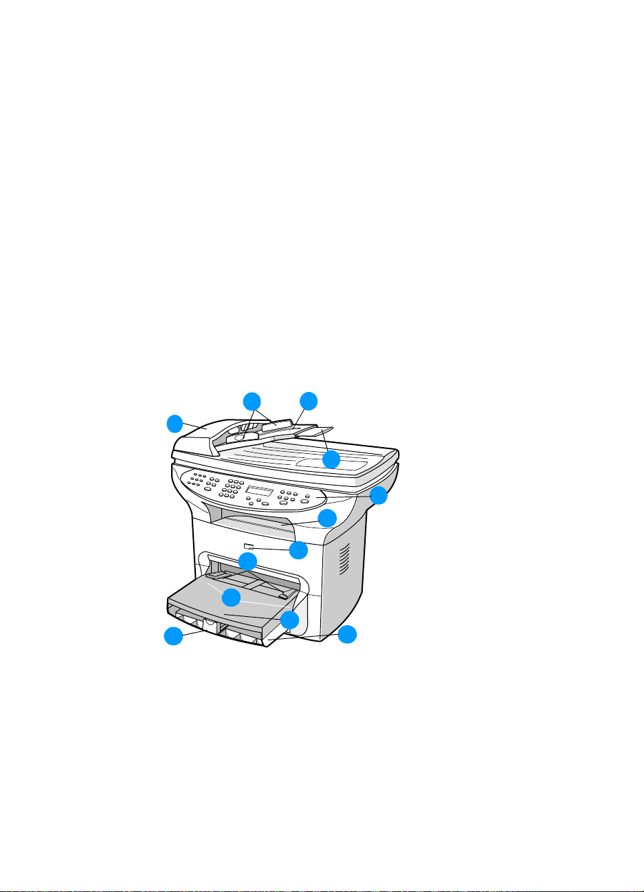
Front and side view
3
1
9
12
10
Figure 1. Front and side view
1
Automatic document feeder (ADF)
2 ADF media input tray
3 Side media guides for the ADF
4 Long media extension for the ADF
5 Control panel
2
4
5
6
7
8
11
6 Output bin
16 Chapter 1 - Product information EN
Page 19
Print cartridge door
7
8 Priority input tray
9 Side media guides for the priority input tray
10 Media support for the main input tray
11 Main input tray
12 Side media guides for the main input tray (inside cover, not
shown)
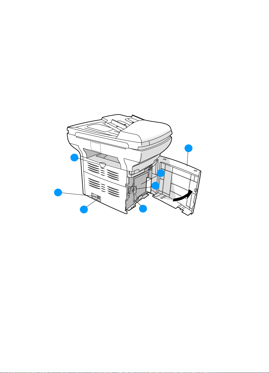
Back and side view
1
2
7
3
6
5
Figure 2. Back and side view
1
Left side panel
2 Straight-through output door
3 USB port
4 Parall el port
5 Power receptacle
6 Power switch (220-240 volt units)
7 LIU (hp LaserJet 3330mfp only...not shown in graphic)
EN Overview of product 17
4
Page 20

Hardware description
The product provides 1200 dot-per-inch (dpi) printing. The flatbed
scanner scans at 600 pixels-per-inch (ppi) with 24-bits per pixel (bpp)
and most models contain an automatic document feeder (ADF) that
holds up to 50 pages. On the HP LaserJet 3330mfp, the formatter
and LIU provide Group-3-compatible faxing capabilities.
The product prints 15 pages per minute (ppm) on letter-size paper or
14 ppm on A4. With 1200 dpi printing resolution, the product has
exceptional text and graphics print quality. The simple control panel
and improved paper handling make this product very easy to use.
The main input tray has a 250-sheet capacity for continuous, multiplepage printing. The priority input tray allows for manual feed of up to
ten sheets. Both trays are center-justified for all supported paper
sizes. The output bin holds up to 125 sheets.
The product has a very fast first-page-out, at less than ten seconds.
The formatter board contains 4 MB of ROM, 32 MB of RAM, and an
embedded 32-bit Coldfire V3 processor. There is one DIMM slot
available for font or memory expansion (supporting an 8 MB, 16 MB,
32 MB, or 64 MB DIMM).
The print engine has a 1,000 average (10,000 peak) page-per-month
duty cycle. The standard toner life is 2,500 pages, and the highcapacity toner life is 3,500 pages with 5% toner coverage.
18 Chapter 1 - Product information EN
Page 21

Firmware description
The firmware in the product includes:
Enhanced PCL 6 with status readback
80 PCL and 80 Postscript™ fonts
Pixel placement, mosaic characters
Memory Enhancement technology (MEt) with hardware
compression and decompression
The firmware also has REt and EconoMode functionality.
Product Specifications
Table 1. Physical specifications
Category Specification
Height 496 mm (19.5 inches)
Depth 520.7 mm (20.5 inches)
Width 546.1 mm (21.5 inches)
Weight (cartridge
installed)
15.9 kg (35.0 lbs) (models with ADF)
14.1 kg (31.1 lbs) (models without ADF)
Table 2. Environmental specifications
Category Specification
Operating
environment (unit
plugged into an AC
outlet)
Storage environment
(unit not plugged
into an AC outlet)
Temperature: 15° to 32.5° C (59° to 90.5° F)
Humidity: 10% to 80% relative humidity
(no condensation)
Temperature: -20° to 40° C (-4° to 104° F)
Humidity: Less than 95% relative humidity
(no condensation)
Table 3. Performance of HP LaserJet 3300mfp series
Category Specification
Print resolution 1200 dpi
Print speed 15 ppm (Letter)
14 ppm (A4)
EN Product Specifications 19
Page 22

Table 4. Performance of ADF for copying/scanning
Category Specification
Scan resolution 600 PPI (24-bit pixels per inch) optical, with 256
levels of gray and 24-bit color
Copy speed Up to 15 ppm
Table 5. Electrical specifications
110-V Models 220-V Models
Power requirements
Note: Power sources are not
interchangeable.
Minimum recommended
circuit capacity
Power consumption Copying (maximum): 330 W
Values subject to change. See http://www.hp.com/support/lj3300 for current information
110 to 127 volts +/-10%
50 to 60 Hz +/-2 Hz
4.5 A at 115 V 2.3 A at 230 V
Printing (maximum): 300 W
Standby: 14 Watts
Power save: 14 Watts
Table 6. Acoustic emissions (HP LaserJet 3300mfp series)
220 to 240V +/-10%,
50 to 60 Hz +/-2 Hz
Copying (maximum): 330 W
Printing (maximum): 300 W
Standby: 14 Watts
Power save: 14 Watts
Off: 0 Watts
Sound Power Level Declared per ISO 9296
Printing (maximum)
Copying (maximum)
Standby/PowerSave
L
= 6.1 Bels (A)
WAd
= 6.6 Bels (A)
L
WAd
Essentially inaudible
SPL Bystander Position Declared per ISO 9296
Printing (maximum)
Copying (maximum)
Standby/PowerSave
Values subject to change. See http://www.hp.com/support/lj3300 for current information. During
other operations, acoustic emissions may vary.
L
= 48 dB (A)
pAm
L
= 50 dB (A)
pAm
Essentially inaudible
20 Chapter 1 - Product information EN
Page 23

Table 7. Skew specifications
Category Specification
Print skew 0.87% (1.65 mm over 190 mm in width) for
cut-sheet media (leading edge)
0.80% (2.0 mm over 250 mm in length) for
cut-sheet media except A5 size
1.50% (3.3 mm over 220 mm in length) for
envelopes, postcards, and A5-size media
The media registration defines how a sheet of media is positioned relative to the
electrophotographic image on the drum. The specified tolerances do not include variation in the
media dimensions from nominal. All vertical lines will be parallel to the reference, or left edge of the
media, within the specifications.
Table 8. HP LaserJet 3330 fax specifications
Category Specification
Fax transmission speed 3 seconds/page (ITU-T Test Image #1 )
Right/left margins for printed
pages
Top/bottom margins for printed
pages
Fax compatibility ITU Group 3; ECM
Fax coding schemes MH, MR, and MMR
Modem speed Up to 33,600 bits per second (bps)
Speed dialing Yes
Distinctive ring detect Yes
Fax resolution (standard) 203 by 98 dots per inch (dpi)
Fax resolution (fine) 203 by 196 dpi
Fax resolution (superfine) 300 by 300 dpi (no halftone)
Fax resolution (photo) 300 by 300 dpi (halftone enabled)
6.3 mm (0.25 inch)
5.08 mm (0.2 inch)
EN Product Specifications 21
Page 24

Model and serial numbers
The model number and serial number are listed on an identification
label located on the inside of the print cartridge door.
The serial number contains information about the country/region of
origin, revision level, production code, and production number of
the product.
The label also contains power rating and regulatory information.
Figure 3. Model and serial number labels
22 Chapter 1 - Product information EN
Page 25

Warranty statement
DURATION OF WARRANTY: One year from date of purchase.
1 HP warrants to you, the end-user customer, that HP hardware, accessories, and
supplies, will be free from defects in materials and workmanship after the date of
purchase, for the period specified above. If HP receives notice of such defects
during the warranty period, HP will, at its option, either repair or replace products
which prove to be defective. Replacement products may be either new or like
new.
2 HP warrants to you that HP software will not fail to execute its programming
instructions after the date of purchase, for the period specified above, due to
defects in material and workmanship when properly installed and used. If
HP receives notice of such defects during the warranty period, HP will replace
software media which does not execute its programming instructions due to such
defects.
3 HP does not warrant that the operation of HP products will be uninterrupted or
error-free. If HP is unable, within a reasonable time, to repair or replace any
product to a condition as warranted, you will be entitled to a refund of the
purchase price upon prompt return of the product.
4 HP products may contain remanufactured parts equivalent to new in performance
or may have been subject to incidental use.
5 Warranty does not apply to defects resulting from (a) improper or inadequate
maintenance or calibration, (b) software, interfacing, parts, or supplies not
supplied by HP, (c) unauthorized modification or misuse, (d) operation outside of
the published environmental specifications for the product, or (d) improper site
preparation or maintenance.
6 HP MAKES NO OTHER EXPRESS WARRANTY OR CONDITION WHETHER
WRITTEN OR ORAL. TO THE EXTENT ALLOWED BY LOCAL LAW, ANY
IMPLIED WARRANTY OR CONDITION OF MERCHANTABILITY,
SATISFACTORY QUALITY, OR FITNESS FOR A PARTICULAR PURPOSE IS
LIMITED TO THE DURATION OF THE EXPRESS WARRANTY SET FORTH
ABOVE. Some countries, states, or provinces do not allow limitations on the
duration of an implied warranty, so the above limitation or exclusion might not
apply to you. This warranty gives you specific legal rights and you might also have
other rights that vary from country to country, state to state, or province to
province.
EN Warranty statement 23
Page 26

7 TO THE EXTENT ALLOWED BY LOCAL LAW, THE REMEDIES IN THIS
WARRANTY STATEMENT ARE YOUR SOLE AND EXCLUSIVE REMEDIES.
EXCEPT AS INDICATED ABOVE, IN NO EVENT WILL HP OR ITS SUPPLIERS
BE LIABLE FOR LOSS OF DATA OR FOR DIRECT, SPECIAL, INCIDENTAL,
CONSEQUENTIAL (INCLUDING LOST PROFIT OR DATA), OR OTHER
DAMAGE, WHETHER BASED IN CONTRACT, TORT, OR OTHERWISE. Some
countries, states, or provinces do not allow the exclusion or limitation of incidental
or consequential damages, so the above limitation or exclusion may not apply to
you.
FOR CONSUMER TRANSACTIONS IN AUSTRALIA AND NEW ZEALAND, THE
WARRANTY TERMS CONTAINED IN THIS STATEMENT, EXCEPT TO THE
EXTENT LAWFULLY PERMITTED, DO NOT EXCLUDE, RESTRICT OR
MODIFY AND ARE IN ADDITION TO THE MANDATORY STATUTORY RIGHTS
APPLICABLE TO THE SALE OF THIS PRODUCT TO YOU.
Extended warranty
HP SupportPack provides coverage for the HP hardware product and
all HP-supplied internal components. The hardware maintenance
warranty covers a three-year period from the date of the HP product
purchase. The customer must purchase the HP SupportPack within
90 days of the HP product purchase. Customers can contact the
nearest HP-authorized dealer about this service.
24 Chapter 1 - Product information EN
Page 27

Print cartridge information
The print cartridge is designed to simplify replacement of the major
consumable parts. The print cartridge contains the printing
mechanism and a supply of toner.
At five percent page coverage, a standard print cartridge will print
approximately 2,500 pages. However, a cartridge should print more
pages if it regularly prints pages with less coverage, such as short
memos. The cartridge might print fewer pages if heavy or bold print is
used.
For best results, always use a print cartridge before the expiration
date stamped on the cartridge box.
Refilled print cartridges
While Hewlett-Packard does not prohibit the use of refilled print
cartridges during the warranty period or while the product is under a
maintenance contract, it is not recommended for the following
reasons:
Repairs resulting from the use of refilled cartridges are not
covered under Hewlett-Packard warranty or maintenance
contracts.
Hewlett-Packard has no control or process to ensure that a
refilled cartridge functions at the high level of reliability of a new
HP LaserJet toner cartridge. Hewlett-Packard also cannot predict
the long-term reliability effect on the product from using different
toner formulations found in refilled cartridges.
The print quality of HP LaserJet print cartridges influences the
customer’s perception of the product. Hewlett-Packard has no
control over the actual print quality of a refilled cartridge.
Parts that are critical to print quality may not be replaced when
the cartridge is refilled with toner.
Recycling print cartridges
In order to reduce waste, Hewlett-Packard offers a recycling program.
Cartridge components that do not wear out are recycled. Plastics and
other materials are recycled. Hewlett-Packard pays the shipping
EN Print cartridge information 25
Page 28

costs from the user to the recycling plant (within the United States).
To join this recycling effort, follow the instructions inside the print
cartridge box.
FCC Part 68 Requirements (US)
This equipment complies with FCC rules, Part 68. On the back of this
equipment is a label that contains, among other information, the FCC
registration number and ringer equivalence number (REN) for this
equipment. If requested, this information must be provided to the
telephone company. The REN is used to determine the quantity of
devices which may be connected to the telephone line. Excessive
RENs on the telephone line may result in the devices not ringing in
response to an incoming call. In most, but not all, areas, the sum of
the RENs should not exceed five (5.0). To be certain of the number of
devices that may be connected to the line, as determined by the total
RENs, contact the telephone company to determine the maximum
REN for the calling area.
This equipment uses the following USOC jacks: RJ11C.
An FCC-compliant telephone cord and modular plug is provided with
this equipment. This equipment is designed to be connected to the
telephone network or premises wiring using a compatible modular
jack which is Part 68-compliant. This equipment cannot be used on
telephone company-provided coin service. Connection to Party Line
Service is subject to state tariffs. If this equipment causes harm to the
telephone network, the telephone company will notify you in advance
that temporary discontinuance of service may be required. If advance
notice isn't practical, the telephone company will notify you as soon
as possible. Also, you will be advised of your right to file a complaint
with the FCC if you believe it is necessary. The telephone company
may make changes in its facilities, equipment, operations, or
procedures that could affect the operation of the equipment. If this
happens, the telephone company will provide advance notice in order
for you to make the necessary modifications in order to maintain
uninterrupted service. If trouble is experienced with this equipment,
please contact HP for repair and (or) warranty information. If the
trouble is causing harm to the telephone network, the telephone
company may request that you remove the equipment from the
network until the problem is resolved. The following repairs can be
done by the customer: replace any original equipment that came with
the product. This includes the print cartridge, the paper trays, the
ADF, the control panel bezel, the ADF pick roller assembly, the power
cord, and the telephone cord. It is recommended that the customer
26 Chapter 1 - Product information EN
Page 29

install an AC surge arrestor in the AC outlet to which this device is
connected. This is to avoid damage to the equipment caused by local
lightning strikes and other ele ctr i c al sur g es.
Telephone Consumer Protection Act (US)
The Telephone Consumer Protection Act of 1991 makes it unlawful
for any person to use a computer or other electronic device, including
fax machines, to send any message unless such message clearly
contains, in a margin at the top or bottom of each transmitted page or
on the first page of the transmission, the date and time it is sent and
an identification of the business, other entity , or individual sending the
message and the telephone number of the sending machine or such
business, other entity, or individual. (The telephone number provided
cannot be a 900 number or any other number for which charges
exceed local or long-distance transmission charges.) In order to
program this information into your facsimile, please see the HP
3300mfp User Guide.
IC CS-03 requirements
NOTICE: The Industry Canada label identifies certified equipment.
This certification means the equipment meets certain
telecommunications network protective, operational, and safety
requirements as prescribed in the appropriate Terminal Equipment
Technical Requirement document(s). The Department does not
guarantee the equipment will operate to the user’s satisfac tion. Bef ore
installing this equipment, users should ensure that it is permissible for
the equipment to be connected to the facilities of the local
telecommunications company. The equipment must also be installed
using an acceptable method of connection. The customer should be
aware that compliance with the above conditions may not prevent
degradation of service in some situations. Repairs to certified
equipment should be coordinated by a representative designated by
the supplier. Any repairs or alterations made by the user to this
equipment, or equipment malfunctions, may give the
telecommunications company cause to request the user to
disconnect the equipment. Users should ensure for their own
protection that the electrical ground connections of the power utility,
telephone lines, and internal metallic water pipe system, if present,
are connected together. This precaution can be particularly important
in rural areas.
Caution: Users should not attempt to make such connections
themselves, but should contact the appropriate electric inspection
authority, or electrician, as appropriate. The Ringer Equivalence
Number (REN) of this device is 0.7.
EN FCC Part 68 Requirements (US) 27
Page 30

Notice: The Ringer Equivalence Number (REN) assigned to each
terminal device provides an indication of the maximum number of
terminals allowed to be connected to a telephone interface. The
termination on an interface may consist of any combination of devices
subject only to the requirement that the sum of the Ringer
Equivalence Number of all the devices does not exceed five (5.0).
The standard connecting arrangement code (telephone jack type) for
equipment with direct connections to the telephone network is
CA11A.
Regulatory information for EU countries
This equipment has been designed to work in all of the countries of
the European Economic Area (Public Switched Telephone Networks)
only . Network compatibility is dependent on internal software settings.
Contact your equipment supplier if it is necessary to use the
equipment on a different telephone network. For further product
support, contact Hewlett-Packard at the phone numbers provided in
the support flyer that came with the product.
28 Chapter 1 - Product information EN
Page 31

2Operation
Chapter contents
Operating environment . . . . . . . . . . . . . . . . . . . . . . . . . . . . . . 30
Identifying the control panel components. . . . . . . . . . . . . . . . . 31
Fax controls . . . . . . . . . . . . . . . . . . . . . . . . . . . . . . . . . . . . 31
To send a fax to one recipient . . . . . . . . . . . . . . . . . . . . . . 31
To receive faxes when you hear fax tones . . . . . . . . . . . . 32
Alphanumeric buttons . . . . . . . . . . . . . . . . . . . . . . . . . . . . 33
Menu and cancel controls . . . . . . . . . . . . . . . . . . . . . . . . . 34
Copy, scan, and start controls. . . . . . . . . . . . . . . . . . . . . . 34
Control panel menu structure. . . . . . . . . . . . . . . . . . . . . . . . . . 35
To print the control panel menu structure . . . . . . . . . . . . . 35
To use the control panel keys . . . . . . . . . . . . . . . . . . . . . . 35
Control panel error messages . . . . . . . . . . . . . . . . . . . . . . . . . 38
Product media specifications . . . . . . . . . . . . . . . . . . . . . . . . . . 45
Supported media sizes (printer). . . . . . . . . . . . . . . . . . . . . 45
Guidelines for using media. . . . . . . . . . . . . . . . . . . . . . . . . . . . 46
Paper and Transparencies . . . . . . . . . . . . . . . . . . . . . . . . 46
Common media problems table. . . . . . . . . . . . . . . . . . . . . 46
Labels . . . . . . . . . . . . . . . . . . . . . . . . . . . . . . . . . . . . . . . . 47
Envelopes . . . . . . . . . . . . . . . . . . . . . . . . . . . . . . . . . . . . . 47
Card stock and heavy media. . . . . . . . . . . . . . . . . . . . . . . 48
Loading media . . . . . . . . . . . . . . . . . . . . . . . . . . . . . . . . . . . . . 49
Loading media to print. . . . . . . . . . . . . . . . . . . . . . . . . . . . 49
Selecting originals for the ADF. . . . . . . . . . . . . . . . . . . . . . . . . 50
Media information for the flatbed . . . . . . . . . . . . . . . . . . . . . . . 51
Loading originals to copy or scan. . . . . . . . . . . . . . . . . . . . . . . 51
To load originals onto the flatbed scanner. . . . . . . . . . . . . 51
To load originals into the ADF input tray . . . . . . . . . . . . . . 52
Printer output paths . . . . . . . . . . . . . . . . . . . . . . . . . . . . . . 54
EN Chapter contents 29
Page 32

Operating environment
Place the product on a sturdy, level surface in a well-ventilated area
that meets the following environmental requirements:
temperature: 15° to 32.5° C (59° to 90.5° F)
humidity: 10% to 80% relative humidity (no condensation)
away from direct sunlight, open flames, and ammonia fumes
sufficient space around the product to allow for proper access
and ventilation
74 cm (29 in)
53 cm (21 i n)
81 cm (32 in)
Figure 4. Dimensions of product
30 Chapter 2 - Operation EN
Page 33

Identifying the control panel components
Fax controls
Fax capability is available on the HP LaserJet 3330 product only. Use
the fax controls to send and receive faxes. These controls and the fax
menu or software are used to change commonly used fax settings.
Figure 5. Fax controls
The HP 3330 has extensive faxing capabilities. This manual
describes only sending a fax to one recipient and receiving a fax. For
a full description of the fax capabilities, see “Faxing” in the User
Guide on the product CD.
To send a fax to one recipient
1 Dial the fax number using one of the following methods:
• Use the alphanumeric buttons on the product’s control panel.
• If the fax number you are calling has been assigned to a one-
touch key, press that key.
• If the fax number you are calling has a speed-dial code, press
speed dial, enter the speed-dial code using the alphanumeric
buttons, and press
Note When dialing with the alphanumeric buttons, include any pauses
or other needed numbers, such as an area code, an access code
for numbers outside a PBX system (usually a 9 or 0), or a longdistance prefix. For more information, see “Using dialing
characters” in the User Guide on the product CD.
EN Identifying the control panel components 31
menu/enter.
Page 34

2 Load the document into the ADF input tray.
3 Press fax/send.
When the last page of the fax has exited the product, you can start
sending another fax, copying, or scanning.
To fax to numbers you use regularly, you can assign a one-touch key
or speed-dial code as described in the User Guide on the product CD.
If you have electronic phone books available, you may be able to use
them for selecting recipients. Electronic phone books are generated
with third-party applications.
Note If y ou want to improve the quality of a paper document before faxing
it, scan the document, straighten or clean the image, and send it
as a fax from the software. For more information, see the product
software Help.
To receive faxes when you hear fax tones
In general, incoming faxes to the product are automatically received.
However, if other devices are connected to the same phone line, the
product may not be set to answer automatically.
If the product is connected to a phone line that receives both fax and
phone calls, and you hear fax tones when you answer the extension
phone, receive the fax in one of two ways:
If you are near the product, press fax/send on the control panel.
Press 1-2-3 in sequence on the extension phone keypad, listen
for fax transmission sounds, then hang up.
Note F or the 1-2-3 sequence to work, the extension phone setting must
be set to Yes in the fax menu.
32 Chapter 2 - Operation EN
Page 35

Alphanumeric buttons
On the HP 3330, use the alphanumeric buttons to enter fax data into
the product’s display screen and dial phone numbers for faxing. For a
full description on using alphanumeric key characters, see “Using
Dialing Characters” in the User Guide on the product CD.
Figure 6. Alphanumeric controls
Note K eypad buttons are numeric on non-fax models and alphanumeric
on the HP LaserJet 3330mfp.
EN Identifying the control panel components 33
Page 36

Menu and cancel controls
Use these controls to choose menu options, determine the product’s
status, and cancel the current job.
Figure 7. Menu and cancel buttons
Copy, scan, and start controls
Use these controls to change commonly used default settings, to start
scanning, and to start copying. For instructions on copying, see
“Copying” in the User Guide. For instructions on scanning, see
“Scanning” in the User Guide. The User Guide is located on the
product CD.
Figure 8. Copy, scan, and start controls
34 Chapter 2 - Operation EN
Page 37

Control panel menu structure
A hierarchical diagram of the control panel menu structure follows.
Refer to this menu structure to make changes to settings and
features.
To print the control panel menu structure
1 Press menu/enter.
2 Use the < or > key to select Reports and then press menu/
enter
.
3 Use the < or > key to select Menu Structure and then press
menu/enter. The product exits the Menu settings and prints the
report.
To see which settings are currently selected, print a configuration
report.
To use the control panel keys
1 Press menu/enter to begin.
2 Use the < or > key to select one of the choices from the main
Menu, and then press
menu/enter.
3 Use the < or > key to select one of the choices from the submenu
and press
4 If applicable, use the < or > key to select one of the choices from
the second submenu and press
EN Control panel menu structure 35
menu/enter.
menu/enter.
Page 38

Table 9. Control panel menu structure
Main Menu Submenu Submenu
Fax Job Status
Fax Functions.............. Send Fax Later
Time/Date, Header...... Time/Date
Copy Setup..... ............. Default Qual i ty
Reports........................ Demo Page
Stop Recv To PC
Reprint Last
Polling Receive
Clear Saved Faxes
Fax Header
Def. Light/Dark
Def. Collation
Def. # Of Copies
Def. Redu/Enlrg
Fax Activity Log....................
Fax Call Report....................
PhoneBook Report
Menu Structure
Config Report
Block Fax List
PCL Font List
PS Font List
All Fax Reports
Print Log Now
Auto Log Print
Print Report Now
Print Report
Include 1st Page
36 Chapter 2 - Operation EN
Page 39

Table 9. Control panel menu structure
Main Menu Submenu Submenu
Fax Setup.................... Phone Book .........................
Fax Send Setup ...................
Fax Recv. Setup..................
All Faxes..............................
Common Settings........ Language
Def. Paper Size
Print Density
Volume Settings................... Alarm Volume
Service......... ................ Print T.30 Trace
Restore Defaults
Cleaning Mode
Power Save T ime
Less Paper Curl
Individual Setup
Add
Delete
Group Setup
Add Group
Delete Group
Del. # In Group
Delete All
Def. Resolution
Def. Light/Dark
Dialing Mode
Redial On Busy
Redial-No Answer
Dial Prefix
Detect Dial Tone
Billing Codes
Answer Mode
Rings To Answer
Answer Ring Type
Extension Phone
Silence Detection
Fit To Page
Stamp Faxes
Forward Fax
Block Faxes
Add Entry
Delete Entry
Clear All
Error Correction
V. 34
Ring Volume
Key Press Volume
EN Control panel menu structure 37
Page 40

Control panel error messages
These control panel error messages are listed alphabetically.
Messages are accompanied by the cau se of the messa ge and us erlevel steps to resolve the problem.
Table 10. Control panel error messages
Message Cause Solution
Cleaning Mode.
Wait 1-3 Min.
Fax Busy.
Canceled Send
### Is Empty
[Enter] To Add
###: [Group Name]
Phbook/SpeedDial
50 Fuser Error
The product is running an internal
cleaning cycle.
The fax line to which you were
sending a fax was busy. The
product has cancelled sending
the fax.
The one-touch key or speed-dial
code has not been programmed
and therefore cannot be added to
a group.
The product is waiting for you to
press a programmed one-touch
key or enter a speed-dial code to
a group-dial code.
The product has experienced an
internal hardware error.
Wait for the product to finish the
cleaning cycle. The message will
clear when the cycle is finished.
Call the recipient to ensure that
the fax machine is on and ready.
Check that you are dialing the
correct fax number.
Check that the redial on busy
option is enabled.
Unplug the product telephone
cord from the wall, plug in a
telephone, and try making a call.
Plug the product phone cord into
a jack for another phone line.
See chapter 6, “Troubleshooting.
”
Press
the one-touch or speed-dial. If
you want to program a groupdial, press
control panel menu to create a
new group. Press
do not want to program the onetouch or speed-dial.
Begin adding fax numbers to the
group-dial code. See
“Programming group-dial codes”
in the User Guide on the product
CD.
Disconnect the power cable from
the product, wait at least 20
minutes, then reconnect the
power cable and wait for the
product to initialize. Try another
power source. If the message
does not clear, see chapter 6,
“Troubleshooting.”
menu/enter to program
cancel and use the
cancel if you
38 Chapter 2 - Operation EN
Page 41

Table 10. Control panel error messages (continued)
Message Cause Solution
51 Laser Error
52 Scanner Error
79 Error
PowerOff>PowerOn
ADF Door Open
Canceled Copy.
Clear Document
Canceled Scan.
Clear Document
The product has experienced an
internal hardware error.
The product has experienced an
internal code error.
The product has experienced an
internal hardware error.
The ADF door is open or a
sensor is malfunctioning.
The cancel key was pressed to
cancel the current job while
pages were feeding from the
document feeder. The cancel
process will not automatically
clear the document feeder.
The cancel key was pressed to
cancel the current job while
pages were feeding from the
document feeder. The cancel
process will not automatically
clear the document feeder.
Disconnect the power cable from
the product, wait at least 30
seconds, then reconnect the
power cable and wait for the
product to initialize. Try another
power source. If the message
does not clear, see chapter 6,
“Troubleshooting.”
Disconnect the power cable from
the product, wait at least 30
seconds, then reconnect the
power cable and wait for the
product to initialize. Try another
power source. If the message
does not clear, see chapter 6,
“Troubleshooting.”
Disconnect the power cable from
the product, wait at least 30
seconds, then reconnect the
power cable and wait for the
product to initialize. If the
message does not clear, see
chapter 6, “Troubleshooting.”
Make sure the ADF door is
closed. If the message persists,
disconnect the power cable from
the product, wait at least 30
seconds, then reconnect the
power cable and wait for the
product to initialize. Try another
power source. If the message
does not clear, see chapter 6,
“Troubleshooting.”
Pull the document release door
open, remove the jammed item,
and close the door. Then, clear
the items in the document feeder
tray and start over.
Pull the document release door
open, remove the jammed item,
and close the door. Then, clear
the items in the document feeder
tray and start over.
EN Control panel error messages 39
Page 42

Table 10. Control panel error messages (continued)
Message Cause Solution
Canceled Send.
Clear Document
CCD Scanner Error
Comm. Error
Device Busy.
Try Again Later
Device Error.
[Enter] To Cont.
Doc Feeder Jam
Document Feeder
Mispick. Reload
Door Open Or No
Print Cartridge
Engine Comm. Error
The cancel key was pressed to
cancel the current job while
pages were feeding from the
document feeder. The cancel
process will not automatically
clear the document feeder.
The scanner assembly
experienced an internal error.
Fax communication error
occurred between the product
and the sender or receiver.
The product is currently in use. Wait for the product to finish the
There was an internal error in the
product.
A piece of media is jammed in
the document feeder tray.
Media in the document feeder
tray was not picked up.
The print cartridge door is open
or the print cartridge is not
installed properly.
The product experienced an
internal communication error.
Pull the document release door
open, remove the jammed item,
and close the door. Then, clear
the items in the document feeder
tray and start over.
Disconnect the power cable from
the product, wait at least 30
seconds, then reconnect the
power cable and wait for the
product to initialize. Try another
power source. If the message
does not clear, see chapter 6,
“Troubleshooting.”
Allow the product to retry sending
the fax.
Unplug the product telephone
cord from the wall, plug in a
telephone, and try making a call.
Plug the product phone cord into
a jack for another phone line.
See chapter 6,
“Troubleshooting.”
current job.
Press menu/enter to resume the
job.
Open the document release
door, clear the jam, close the
document release door, and
reload the paper into the
document feeder tray.
Remove and reload the media
into the document feeder tray.
Make sure the print cartridge
door is closed. Check the print
cartridge for proper installation.
Warning message only. Job
output may be affected.
40 Chapter 2 - Operation EN
Page 43

Table 10. Control panel error messages (continued)
Message Cause Solution
Fax Busy.
Redial Pending
Fax Memory Full
Canceling Recv
Fax Memory Full
Canceling Send
Fax Recv Error
The fax line to which you were
sending a fax was busy. The
product automatically redials the
busy number. (See “Changing
how the product redials” in the
User Guide on the product CD.)
During the fax transmission, the
product ran out of memory. Only
the pages that fit into memory will
be printed.
During the fax job, the memory
filled. All pages of the fax have to
be in memory for a fax job to
work correctly. Only the pages
that fit into me mory were se n t .
An error occurred while trying to
receive a fax.
Allow the product to retry sending
the fax.
Call the recipient to ensure that
the fax machine is on and ready.
Check that you are dialing the
correct fax number.
Unplug the product telephone
cord from the wall, plug in a
telephone, and try making a call.
Plug the product phone cord into
a jack for another phone line.
See chapter 6,
“Troubleshooting.”
Print all of the faxes and have the
sender resend the fax. Cancel all
fax jobs or clear the faxes from
memory (see “Clearing faxes
from memory” in the User Guide
on the product CD).
Print all received faxes or wait
until all pending faxes are sent.
Cancel all fax jobs or clear the
faxes from memory (see
“Clearing faxes from memory” in
the User Guide on the product
CD).
Ask the sender to resend the fax.
Try faxing back to sender or
another fax machine.
Check that the telephone cord is
securely connected by
unplugging and replugging the
cord.
Check for a dial tone on the
phone line by pressing
Make sure the phone is working
by disconnecting the product,
plugging in a telephone to the
phone line, and making a voice
call.
Connect the product to a different
phone line.
fax/send.
EN Control panel error messages 41
Page 44

Table 10. Control panel error messages (continued)
Message Cause Solution
Fax Send Error
Fit to Page on
Flatbed Only
Group Dial Not
Allowed In Group
Group Is Full.
[Fax] To Start
Invalid Date
Invalid Entry
Memory Low.
Press [Cancel]
Memory Low.1 Copy.
Press [Cancel]
Memory Low
Only 1 Copy Made
An error occurred while trying to
send a fax.
Fit to Page does not work when
the ADF is being used.
The speed-dial code you entered
is programmed for a group.
Adding a group-dial to another
group-dial is not allowed.
The maximum number of fax
numbers that can be added to an
ad hoc group is 20.
An invalid date was entered,
such as June 35.
Invalid data or response. Correct the entry.
The product memory has been
almost completely filled.
The product completed making
one copy. The remaining copies
have been canceled because of
low product memory.
The product does not have
enough memory to complete the
collated copy job.
Try resending the fax.
Try faxing to another fax number.
Check that the telephone cord is
securely connected by
unplugging and replugging the
cord.
Check for a dial tone on the
phone line by pressing
Make sure the phone is working
by disconnecting the product,
plugging in a telephone to the
phone line, and making a voice
call.
Connect the product to a different
phone line.
Use the flatbed or choose
another reduction/enlargement
setting.
Enter one-touch keys
(programmed as an individual
speed dial) or speed-dial codes
to a group-dial
Resend to the ad hoc group
using less fax numbers.
Reenter the date.
Allow the product to finish the job
or press
Press
Use the HP LaserJet Director to
make multiple copies of large
documents, or break the job into
smaller jobs containing fewer
pages.
Reduce job size or copy one at a
time.
fax/send.
cancel to cancel the job.
cancel to clear the error.
42 Chapter 2 - Operation EN
Page 45

Table 10. Control panel error messages (continued)
Message Cause Solution
No Dial Tone.
No Document Sent
No Fax Answer.
Canceled Send
No Fax Answer.
Redial Pending
The product could not detect a
dial tone.
The fax forwarding setting is on
and the product was
unsuccessful at receiving a fax
because of low memory or some
other reason. The product
deleted the partially received fax
data and did not attempt to
forward it.
Attempts to redial a fax number
failed or the “Redial on no
answer” option was turned off.
You tried to send a fax, but the
receiving fax line did not answer.
The product attempts to redial
after a few minutes.
Unplug the telephone cord from
both the product and the wall and
replug the cord.
Unplug the product telephone
cord from the wall, plug in a
telephone, and try making a call.
Plug the product phone cord into
a jack for another phone line.
See “Changing the detect dial
tone setting” in the User Guide
on the product CD. Also see
chapter 6, “Troubleshooting.”
Print the faxes in memory and
have the sender resend the
missing page(s) of the document.
Call the recipient to ensure that
the fax machine is on and ready.
Check that you are dialing the
correct fax number. Check that
the redial option is enabled.
Unplug the telephone cord from
both the product and the wall and
replug the cord. Unplug the
product telephone cord from the
wall, plug in a telephone, and try
making a call. Plug the product
phone cord into a jack for another
phone line. See chapter 6,
“Troubleshooting.”
Allow the product to retry sending
the fax.
Call the recipient to ensure that
the fax machine is on and ready.
Check that you are dialing the
correct fax number.
Check that the redial on no
answer option is enabled.
Unplug the product telephone
cord from the wall, plug in a
telephone, and try making a call.
Plug the product phone cord into
a jack for another phone line.
See chapter 6,
“Troubleshooting.”
EN Control panel error messages 43
Page 46

Table 10. Control panel error messages (continued)
Message Cause Solution
No Fax Detected
No Fax Pages
To Reprint
Not Enough
Memory.Try Later
Out of Range
Printer Jam.
Clear Paper Path
Printer Mispick
[Enter]To Resume
Printer Tray Is
Empty.Add Paper
Scanner Bulb Failure
Scanner Reserved
For PC Scan
Scanning Error.
Cannot Connect
Settings Cleared
Time/Date is in Past.
Try Again
The product answered the
incoming call but did not detect
that a fax machine was calling.
The product attempted to
execute “Reprint Last Fax” when
nothing was in memory.
There is not enough memory to
start a new job.
An invalid number was entered. Correct the entry.
The product has detected that a
jam has occurred.
The print engine has failed to
pick up a piece of media.
The paper input tray is empty. Load media. If media is already
The scanner assembly
experienced an error in scanner
bulb functionality.
The product is being used to
create a scan by a computer.
The product cannot transmit scan
information to a computer.
The product has cleared job
settings.
Invalid date or time entry. Enter the correct time or date.
Allow the product to retry
receiving the fax.
Unplug the product telephone
cord from the wall, plug in a
telephone, and try making a call.
Plug the product phone cord into
a jack for another phone line.
See chapter 6,
“Troubleshooting.”
Receive a fax before attempting
to use this option.
Wait until the current job is
finished before starting a new
job.
Clear the jam. The job should
continue to print. If it does not, try
reprinting the job.
Reload the paper in the paper
input tray and press
to continue the job.
loaded, remove it. Check for and
remove any jam, and then reload
the stack of media in the paper
input tray.
Disconnect the power cable from
the product, wait at least 30
seconds, then reconnect the
power cable and wait for the
product to initialize. Try another
power source. If the message
does not clear, see chapter 6,
“Troubleshooting.”
Wait until the PC scan has
finished, or cancel the scan from
the computer software, or press
cancel.
Check the connection cable and
try the scan again.
Reenter any desired job settings.
menu/enter
44 Chapter 2 - Operation EN
Page 47

Product media specifications
The product accepts a variety of media. Properties such as weight,
grain, and moisture content are important factors affecting printer
performance and output quality. Media should conform to the
guidelines in the User Guide located on the product CD. Media that
does not meet HP guidelines might cause poor print quality,
increased media jams, or premature wear on the product. This may
require repair.
CAUTION Damage caused by media that does not meet HP’s specifications
is not covered by the HP warranty or service agreements.
Supported media sizes (printer)
The printer supports media within these sizes:
Minimum: 76 x 127 mm (3 x 5 in)
Maximum: 216 x 356 mm (8.5 x 14 in)
Table 11. Media types
Paper type Metric English
Letter 216 by 279 mm 8.5 by 11 in
Legal 216 by 356 mm 8.5 by 14 in
Executive 184 by 267 mm 7.25 by 10.5 in
A4 210 by 297 mm 8.25 by 11.75 in
COM10 Envelopes 105 by 241 mm 4.13 by 9.5 in
DL Envelopes 110 by 220 mm 4.33 by 8.67 in
C5 Envelopes 162 by 229 mm 6.4 by 9 in
B5 Envelopes 176 by 250 mm 6.9 by 9.85 in
Monarch Envelopes 98.5 by 191 mm 3.88 by 7.5 in
Custom size media custom custom
Note Narrow and heavy media can cause the printer to print slower.
EN Product media specifications 45
Page 48

Guidelines for using media
Paper and Transparencies
Paper must be of good quality and free of cuts, nicks, tears, spots,
loose particles, dust, wrinkles, holes, and curled or bent edges.
Check the label on the paper package for details about the type of
paper (such as bond or recycled).
Some paper causes print quality problems, jamming, or damage to
the printer.
Note Do not use letterhead that is printed with low-temperature inks,
such as those used in some types of thermography, raised
letterhead, or colored paper or preprinted forms that use inks
incompatible with the printer temperature (200° C or 392° F for
0.1 second).
Transparencies must be able to withstand 200° C (392° F), the
printer’s maximum temperature.
Common media problems table
Symptom Problem with paper Solution
Poor print quality or toner
adhesion, or problems with
feeding.
Dropouts, jamming, or curl. Stored improperly. Store paper flat in its
Increased gray background
shading.
Excessive curl, or problems
with feeding.
Jamming, or damage to
printer.
Problems with feeding. Ragged edges. Use good quality paper.
Too moist, too rough, too
smooth, or embossed.
Faulty paper lot.
Might be too heavy. Use lighter paper.
Too moist, wrong grain
direction, or short-grain
construction.
Cutouts or perforation s. Do not use paper with cuto uts
Try another kind of paper
between 100 and 250
Sheffield and 4 to 6%
moisture content.
moisture-proof wrapping.
Use long-grain paper.
Print using the straight-
through output path.
or perforations.
46 Chapter 2 - Operation EN
Page 49

Labels
When selecting labels, consider the quality of the following factors:
Adhesives: The adhesive material should be stable at 200° C
(392° F), the printer’s maximum temperature.
Arrangement: Only use labels with no exposed backing between
them. Labels can peel off sheets that have spaces between the
labels, causing serious jams.
Curl: Prior to printing, labels must lie flat with no more than
13 mm (0.5 in) of curl in any direction.
Condition: Do not use labels with wrinkles, bubbles, or other
indications of separation. Never use a sheet of labels that has
already been run through the printer.
Envelopes
Envelope construction is critical. Envelope fold lines can vary
considerably, not only between manufacturers, but also within a box
from the same manufacturer. Successful printing on envelopes
depends on the quality of the envelopes. When selecting envelopes,
consider the following factors:
Weight: The weight of the envelope paper should not exceed 105
Construction: Prior to printing, envelopes should lie flat with less
2
(28 lb), or jamming might result.
g/m
than 6 mm (0.25 in) curl and should not contain air. Envelopes
that trap air may cause problems.
Condition: Make sure that the envelopes are not wrinkled,
nicked, or otherwise damaged.
Sizes: From 90 x 160 mm (3.5 x 6.3 in) to 178 x 254 mm
(7 x 10
in).
Store envelopes flat. If air is trapped in an envelope, creating an air
bubble, the envelope might wrinkle during printing.
EN Guidelines for using media 47
Page 50

Envelopes with double-side seams
An envelope with double-side-seam construction (vertical seams at
both ends of the envelope rather than diagonal seams) is more likely
to wrinkle. Make sure the seam extends all the way to the corner of
the envelope as shown in the following illustration:
Acceptable
Unacceptable
Envelopes with adhesive strips or flaps
Envelopes with a peel-off adhesive strip or with more than one flap
that folds over to seal must use adhesives compatible with the heat
and pressure in the printer: 200° C (392° F). The extra flaps and
strips might cause wrinkling, creasing, or jams.
Card stock and heavy media
For optimum performance, do not use paper heavier than 157 g/m2
(42-pound). Paper that is too heavy might cause misfeeds, stacking
problems, paper jams, poor toner fusing, poor print quality, or
excessive mechanical wear.
Note You might be able to print on heavier paper if you do not fill the
input tray to capacity and if you use paper with a smoothness rating
of 100 to 180 Sheffield.
48 Chapter 2 - Operation EN
Page 51

Card stock construction
Smoothness: 135-157 g/m
have a smoothness rating of 100 to 180 Sheffield. 60-135 g/m
(16- to 36-pound) card stock should have a smoothness rating of
100 to 250 Sheffield.
Construction: Card stock should lie flat with less than 5 mm
(0.2 in) of curl.
Condition: Make sure that the card stock is not wrinkled, nicked,
or otherwise damaged.
Sizes: Only use card stock within the following size ranges:
Minimum: 76 x 127 mm (3 x 5 in)
•
•
Maximum: 216 x 356 mm (8.5 x 14 in)
Card stock guidelines
If the card stock curls or jams, print using the straight-through
output path.
Set margins at least 2 mm (0.08 in) away from the edges.
Loading media
2
(36-to 42-pound) card stock should
2
Loading media to print
Main input tray
The main input tray holds up to 250 sheets of 75 g/m2 (20 lb) paper or
a 25 mm (0.98
forward and the side to be printed facing up. To prevent jams and
skew, always adjust the side media guides.
Priority input tray
The priority input tray holds up to ten pages of 75 g/m2 (20 lb) paper
or one envelope, transparency, or card. Load media with the top
forward and the side to be printed facing up. To prevent jams and
skew, always adjust the side media guides.
CAUTION If you try to print on media that is wrinkled, folded, or damaged in
any way, a jam might occur. See the User Guide located on the
product CD for more information.
EN Loading media 49
in) stack of heavier media. Load media with the top
Page 52

Note When you add new media, make sure that you remove all of the
media from the input tray and straighten the stack of new media.
This helps prevent multiple sheets of media from feeding through
the printer at one time, reducing paper jams.
Specific types of media
Transparencies and labels: Load transparencies and labels
with the top forward and the side to be printed facing up. See the
User Guide located on the product CD for more information.
Envelopes: Load envelopes with the narrow, stamp side forward
and the side to be printed facing up. See the User Guide located
on the product CD for more information.
Letterhead or preprinted forms: Load with the top forward and
the side to be printed facing up. See the User Guide for more
information.
Cards and custom-sized media: Load with the narrow side
forward and the side to be printed facing up. See the User Guide
located on the product CD for more information.
Selecting originals for the ADF
The ADF is recommended for plain paper copying, scanning, and
faxing (faxing can be done only from the ADF).
Note If you w ant to fax an original that is not appropriate for the ADF,
make a copy of it first on the flatbed, then fax the copy.
ADF originals specifications
Input capacity: The ADF holds up to 50 sheets of flat 60 to
90g/m (16- to 24-pound) plain paper.
Media size: Only use plain paper within the following size ranges:
•
Minimum: 127 mm x 127 mm (5 x 5 in)
• Maximum: 215.9 mm x 381 mm (8.5 x 15 in)
Note You must use the flatbed to scan or copy small or delicate originals
(such as newsprints, business cards, and photos), or documents
with tears, perforations, or punch holes. If you want to fax such
items, make a copy first on the flatbed and then fax the copy.
50 Chapter 2 - Operation EN
Page 53

Perform the following actions to minimize the possibility of jams:
Remove self-stick notes.
Remove staples and paper clips.
Straighten any curls, folds, or wrinkles in documents before
putting them into the document feeder tray.
Do not insert any document with glue, correction fluid, or wet ink
on it.
Do not insert gum-backed paper or labels.
Avoid multiple-copy forms.
Do not scan originals that are larger or smaller than supported
size limitations. See the User Guide for more information.
Note To obtain good results, it is important that you use the correct
resolution and color settings for your job. See the User Guide
located on the product CD for more information.
Media information for the flatbed
Use the flatbed scanner for copying and scanning if the media is
fragile, thin, thick, or damaged (folded, wrinkled). The flatbed scanner
provides the best copy and scan quality.
The flatbed has no minimum size and a maximum size of legal. In
order to make a copy of a legal-size document, the paper size must
be changed using the
paper size button. Otherwis e, the co py wil l be
cropped to the default paper size.
Loading originals to copy or scan
Use these instructions to load originals into your HP LaserJet
3300mfp series for copying or scanning. For the best-quality scans
and copies, use the flatbed scanner. See "Selecting originals for the
ADF" for guidelines on choosing original documents for scanning and
copying.
If you purchased an HP LaserJet 3300mfp and want to purchase an
ADF, see the User Guide located on the product CD for more
information.
To load originals onto the flatbed scanner
1 Make sure the ADF is free of media.
EN Media information for the flatbed 51
Page 54

2 Lift the flatbed scanner cover.
3 Place the original document facedown on the flatbed scanner
with the top left corner of the document located in the lower right
corner of the glass.
4 Gently close the lid.
5 The document is ready to be copied or scanned.
CAUTION To prevent damage to the product, do not allow the scanner lid to
fall onto the flatbed scanner surface. Always close the scanner lid
when the product is not in use.
To load originals into the ADF input tray
ADF capacity is up to 50 sheets of 75 g/m2 (20-pound) media
(depending on the thickness of the media), or until the ADF input tray
is full.
The minimum size for media in the ADF is 127 x 127 mm (5 x 5
For smaller sizes use the flatbed scanner. The maximum size for
media in the ADF is 215.9 mm wide by 381 mm long (8.5 x 15
1 Make sure the flatbed scanner is free of media.
2 Close the flatbed scanner cover and put the top end of the
original media stack into the ADF input tray, with the media stack
faceup and the first page to be scanned, copied, or faxed on top
of the stack.
52 Chapter 2 - Operation EN
in).
in).
Page 55

Slide the media stack into the ADF until the media does not move
3
any farther.
4 Adjust the media guides until they are snug.
5 The document is now ready to be copied or scanned.
6 After scanning, the document will be delivered to the output tray
in the correct order.
EN Loading originals to copy or scan 53
Page 56

Printer output paths
Output bin and straight-through output path
The output bin is located between the scanner and the printer. Printed
media is collected here in the correct sequence when the straightthrough output door is closed. Use the output bin when printing
normal and large collated documents.
The straight-through output path is useful when you are printing
envelopes, transparencies, heavy media, or any media that tends to
curl when printed. Printed media exits in reverse order when the
straight-through output door is open.
Figure 9. Output bin and straight-through output path
Note Printed media does not stack when you use the straight-through
output path. The media drops to the surface below unless you
remove each sheet as it exits the printer.
54 Chapter 2 - Operation EN
Page 57

3Maintenance
Chapter contents
Life expectancies of parts that wear . . . . . . . . . . . . . . . . . . . . . . . . 56
Scanner calibration . . . . . . . . . . . . . . . . . . . . . . . . . . . . . . . . . . . . . 56
Cleaning the product . . . . . . . . . . . . . . . . . . . . . . . . . . . . . . . . . . . . 57
Cleaning the exterior. . . . . . . . . . . . . . . . . . . . . . . . . . . . . . . . . 57
Cleaning the glass . . . . . . . . . . . . . . . . . . . . . . . . . . . . . . . . . . 57
Cleaning the lid backing . . . . . . . . . . . . . . . . . . . . . . . . . . . . . . 58
Cleaning the print path . . . . . . . . . . . . . . . . . . . . . . . . . . . . . . . 59
Cleaning the print cartridge area. . . . . . . . . . . . . . . . . . . . . . . . 60
Cleaning the printer pickup roller . . . . . . . . . . . . . . . . . . . . . . . 61
Cleaning the printer separation pad . . . . . . . . . . . . . . . . . . . . . 62
User-replaceable parts . . . . . . . . . . . . . . . . . . . . . . . . . . . . . . . . . . 63
Replacing the printer pickup roller . . . . . . . . . . . . . . . . . . . . . . 63
Replacing the printer separation pad . . . . . . . . . . . . . . . . . . . . 65
Installing a new ADF . . . . . . . . . . . . . . . . . . . . . . . . . . . . . . . . . . . . 67
To install a new or replacement ADF . . . . . . . . . . . . . . . . . . . . 67
Changing an ADF pick roller assembly . . . . . . . . . . . . . . . . . . . . . . 69
Removing and replacing the control panel bezel . . . . . . . . . . . . . . 71
EN Chapter contents 55
Page 58

Life expectancies of parts that wear
Inspect any parts that wear when servicing the product. Replace
them as needed, based on failure or wear, rather than on usage.
The following table lists approximate schedules for replacing
consumables.
Table 12. Life expectancies of parts that wear
Description Part number Life (est.) Remarks
Print cartridge* (userreplaceable)
Printer transfer roller RG9-1483-000CN 25,000
Printer pickup roller RF0-1008-000CN 25,000
Printer separation pad RF0-1014-020CN 25,000
Fuser assembly
(100-127 V)
Fuser assembly
(220-240 V)
ADF separation pad C7309-60009 25,000
ADF C9143-60101 25,000
ADF pick roller assembly C7309-60016 25,000
* The estimated print cartridge life is based on letter- or A4-sized paper with an average of five percent
toner coverage and a medium density setting. Print cartridge life can be extended further by conserving
toner using draft mode settings.
C7115A 2,500 pages When print becomes faint,
C7115X 3,500 pages
pages
pages
pages
RG9-1493-030CN 25,000
pages
RG9-1494-030CN 25,000
pages
pages
pages
pages
redistribute toner in the cartridge
by gently shaking the cartridge
from side to side.
Can affect print quality and/or
paper movement.
Look for glazing and/or cracks.
Can affect paper movement.
Can affect print quality and paper
movement.
Can affect print quality and paper
movement.
Can affect movement of
documents to be scanned or
copied.
Can affect movement of
documents to be scanned or
copied.
Can affect movement of
documents to be scanned or
copied.
Scanner calibration
The scanner calibrates itself automatically at the start of scan of copy
jobs. Normally, you don’t need to initiate the calibration, but you can
initiate the calibration through the secondary service menu and
produce a report that shows the calibration results (page 229).
56 Chapter 3 - Maintenance EN
Page 59

Cleaning the product
WARNING! Before you perform these steps, unplug the product to avoid shock
hazard.
To maintain quality, thoroughly clean the product:
Any time a new print cartridge is installed.
After printing approximately 2,500 pages.
Whenever print quality pr obl ems appea r.
Clean the outside of the product with a water-dampened cloth. Clean
the inside with only a dry, lint-free cloth (such as a lens tissue).
To avoid permanent damage to the print cartridge, do not use
ammonia-based or ethyl alcohol-based cleaners on or around the
product.
WARNING! Avoid touching the heating element in the fuser. It might be very hot
and can cause burns.
CAUTION Do not touch the surface of the black sponge transfer roller.
Contaminants on the roller can cause print quality problems.
Cleaning the exterior
Use a soft, damp, lint-free cloth to wipe dust, smudges, and stains off
the exterior of the product.
Cleaning the glass
Dirty glass (from fingerprints, smudges, hair, and so on) reduces
quality, slows down performance, and affects the accuracy of special
features such as fit to page and copy.
1 Turn off the product, unplug the power cord from the electrical
socket, and raise the lid.
Note If you have a 220V product, turn off the power switch.
2 Clean the glass with a soft cloth or sponge slightly moistened with
nonabrasive glass cleaner.
EN Cleaning the product 57
Page 60

CAUTION Do not use abrasives, acetone, benzene, ethyl alcohol, or carbon
tetrachloride on the glass; these can damage it. Do not place
liquids directly on the glass. They may seep under it and damage
the product.
3 Dry the glass with a chamois or cellulose sponge to prevent
spotting.
Note Dust might appear on the underside of the glass, but this cannot
be cleaned and it has no effect on the copy or scan quality.
Cleaning the lid backing
Minor debris can accumulate on the white document lid backing
located underneath the product’s lid.
1 Turn off the product, unplug the power cord from the electrical
socket, and raise the lid.
Note If you have a 220V product, turn off the power switch.
2 Clean the white document lid backing with a soft cloth or sponge
slightly moistened with a mild soap and warm water.
3 Wash the backing gently to loosen debris; do not scrub the
backing.
4 Dry the backing with a chamois or soft cloth.
CAUTION Do not use paper-based wipes as these may scratch the backing.
5 If this does not clean the backing well enough, repeat the
previous steps using isopropyl alcohol, and then wipe the backing
thoroughly with a damp cloth to remove any residual alcohol.
58 Chapter 3 - Maintenance EN
Page 61

Cleaning the print path
The HP LaserJet 3300mfp series features a special cleaning mode to
clean the paper path.
Note This process requires a transparency to remove dust and toner
from the print paper path. Do not use bond or rough paper.
Make sure the transparency used in this cleaning process meets
the media requirements for the printer.
If transparency film is unavailable, you can use paper. If you must
use paper, perform the procedure two or three times to ensure
proper cleaning.
1 Load a transparency in the priority input tray.
2 Make sure that the product is in the Ready state.
3 Press menu/enter then scroll to Service and press menu/enter
4
Scroll to Cleaning Mode and press menu/enter.
5 The transparency feeds through the printer slowly. Discard the
transparency.
Note The fax/send and cancel lights blink until the cleaning process is
complete.
EN Cleaning the product 59
Page 62

1
Cleaning the print cartridge area
Cleaning the print cartridge area can
improve the quality of your printed
sheets.
2
3
4
WARNING!
Before cleaning the product, disconnect
it from the power source and wait for the
product to cool.
1 Open the print cartridge door, and
remove the print cartridge.
CAUTION
To prevent damage, do not expose the
print cartridge to light. Cover the print
cartridge if necessary. Also, do not touch
the black sponge transfer roller inside
the printer. Touching it can reduce the
print quality.
2 Wipe the media path area and the
print cartridge cavity with a dry, lintfree cloth.
Note
Use only a dry, lint-free cloth to remove
dust and toner. Using a vacuum or other
device to clean inside the product can
damage it.
3 Replace the print ca rtridge, and
close the print cartridge door.
4 Plug the power cord back into the
product.
60 Chapter 3 - Maintenance EN
Page 63

1
Cleaning the printer pickup roller
If you want to clean the pickup roller
rather than replace it, follow the
instructions below:
Remove the pickup roller as described in
2
3
steps 1 through 5 of “Replacing the
printer pickup roller” on page 63.
1 Dampen a lint-free cloth in isopropyl
alcohol and scrub the roller.
WARNING!
Alcohol is flammable. Keep the alcohol
and cloth away from an open flame.
Before you close the product and plug in
the power cord, allow the alcohol to dry
completely.
2 Using a dry, lint-free cl oth, wipe the
pickup roller to remove loosened
dirt.
3 Allow the pickup roller to dry
completely before you reinstall it in
the printer. To reinstall the pickup
roller, see steps 6 through 9 of
"Replacing the printer pickup roller"
on page 64 .
EN Cleaning the product 61
Page 64

1
Cleaning the printer separation pad
If you want to clean the separation pad
rather than replace it, follow the
instructions below:
1 Remove the separation pad as
2
3
described in steps 1 through 5 of
“Replacing the printer separation
pad” on page 65.
2 Dab a lint-free cloth in isopropyl
alcohol, and scrub the pad.
WARNING!
Alcohol is flammable. Keep the alcohol
and cloth away from an open flame.
Before you close the product and plug in
the power cord, allow the alcohol to dry
completely.
3 Using a dry, lint-free cl oth, wipe the
pad to remove loosened dirt.
4
62 Chapter 3 - Maintenance EN
4 Allow the pad to dry completely
before you reinstall it in the printer.
To reinstall the pad, see steps 6
through 8 of “Replacing the printer
separation pad” on page 65.
Page 65

User-replaceable parts
1
Replacing the printer pickup roller
If the printer regularly misfeeds (no
media feeds through) and cleaning the
pickup roller does not fix it, replace the
pickup roller.
2
3
CAUTION
Failure to complete all the steps in this
procedure might damage the product.
1 Unplug the power cord from the
product, and allow the product to
cool.
2 Open the print cartridge door, and
remove the print cartridge.
3 Locate the pickup roller.
4
5
EN User-replaceable parts 63
4 Release the small, white tabs on
each side of the pickup roller by
pushing them away from the roller,
and then rotate the pickup roller
toward the front.
5 Gently pull the pickup roller up and
out.
Page 66

6
6 Position the new pickup roller in the
slot of the previous pickup roller.
Note
Circular and rectangular pegs on each
side prevent you from incorrectly
positioning the pickup roller.
7
8
9
7 Rotate the top of the new pickup
roller into position until the white
tabs on each side of the roller snap
the roller into place.
8 Reinstall the print cartridge and
close the print cartridge door.
9 Plug the product in to turn it back on.
64 Chapter 3 - Maintenance EN
Page 67

1
Replacing the printer separation pad
Note
Before you change the separation pad,
clean the pickup roller. See “Cleaning
2
the printer pickup roller” on page 61 for
instructions.
If the input tray feeds more than one
page at a time, you might have to
replace the printer separation pad.
Recurring feed problems indicate that
the printer separation pad is worn.
3
4
5
1 Unplug the power cord from the
product and allow the product to
cool.
2 Remove the input trays.
3 Locate the blue separation pad.
4 To pry the separation pad up from
the spring-loaded base, insert a flatedged screwdriver in the slot under
the separation pad and twist until the
tabs are free.
5 Reach in through the input tray
opening, push the spring-loaded
base down with one hand, and pull
the separation pad up with the other
hand.
EN User-replaceable parts 65
Page 68

6
6 With one hand, reach through the
input tray opening, and push the
spring-loaded base down. With the
other hand, position the new
separation pad in the slot of the
previous separation pad.
Note
7
The tab on the right is larger to help you
position the separation pad correctly.
7 Snap both sides of the separation
pad firmly into place.
CAUTION
Make sure that the separation pad is
straight and that there is no space
between the separation pad and the
spring-loaded base. If the separation
pad is not straight or you see space on
one side, remove the separation pad,
make sure that the larger tab is on the
right, reinsert the separation pad, and
snap both sides into place.
8
8 Reinstall the input trays, and then
plug the product in to turn it back on.
66 Chapter 3 - Maintenance EN
Page 69

Installing a new ADF
If the HP LaserJet 3300mfp came without an ADF, an ADF can be
added. An ADF may need to be replaced if it has abnormal media
jams.
To install a new or
1
2
3
replacement ADF
1 Remove the flatbed scanner lid by
opening it and gently lifting straight
up.
Note
If you are replacing an existing ADF, you
must first pull up both hinge tabs before
lifting the ADF up out of the product.
2 On the new ADF, unfold the hinges
and pull up the tab on each hinge.
3 Install the new ADF by inserting the
hinges straight down into the
product.
4 Push down both tabs until they click.
4
EN Installing a new ADF 67
Page 70

5
5 Gently close the ADF lid.
WARNING!
To avoid damaging the product, do not
allow the ADF lid to fall onto the flatbed
scanner. Always close the ADF lid when
the product is not in use.
6
6 Install the ADF input tray by aligning
the two tabs on the input tray with
the two grooves in the ADF lid and
sliding the tray into the grooves until
it snaps into place.
68 Chapter 3 - Maintenance EN
Page 71

Changing an ADF pick roller assembly
If the ADF has trouble picking paper, the ADF pick roller assembly
may need to be replaced:
1
2
3
1 Unplug the power cord from the
product. If you have a 220V product,
turn off the power switch.
2 Remove the input tray and open the
ADF cover.
3 Press the round green button while
lifting the green lever. Rotate the
green lever until it stops in the open
position. The old pickup roller
assembly should remain on the
black surface.
4
5
EN Changing an ADF pick roller assembly 69
4 Remove the old assembly and put
the new one in exactly the same
place. The largest roller goes in
back, and the gear side will face
away from you.
5 Lower the green lever with the flat
green part fitting in between the
rollers. Press down on the green
lever until it snaps in place.
Page 72

6
6 To check for proper installation, lift
the green lever until it remains open.
The new pickup roller assembly
should be secured to the lever
assembly and should not fall out.
7
8
7 Make sure that both sides of the
assembly are secured by the green
hooks.
8 Lower the green lever assembly and
close the ADF lid. Reinstall the input
tray.
If you are experiencing abnormal jams in
the ADF, you may wan t to order a new
ADF, or upgrade the ADF copy lid. See
"User-replaceable parts".
70 Chapter 3 - Maintenance EN
Page 73

Removing and replacing the control panel bezel
1
2
3
1 Unplug the power cord from the
product. If you have a 220V product,
turn off the power switch.
2 Remove the existing control panel
bezel by lifting up on both sides of
the bezel edges until all the snaps
are disengaged. Set the old bezel
aside.
CAUTION
Be careful not to touch any components
or buttons inside the exposed control
panel area.
3 Align the new bezel at the lower
notch. The bezel notch should align
to the inside of the product.
4 Press down until all the snaps are
4
EN Removing and replacing the control panel bezel 71
engaged, and then press outward
until the bezel is secured.
5 Plug the product in to turn it back on.
If you have a 220V product, turn on
the power switch.
Page 74

72 Chapter 3 - Maintenance EN
Page 75

4Operational overview
Chapter contents
Basic functions. . . . . . . . . . . . . . . . . . . . . . . . . . . . . . . . . . . . . 74
Formatter system . . . . . . . . . . . . . . . . . . . . . . . . . . . . . . . . . . . 76
Central processing unit . . . . . . . . . . . . . . . . . . . . . . . . . . . 76
Line Interface Unit (LIU). . . . . . . . . . . . . . . . . . . . . . . . . . . 76
Scanner formatter PCA . . . . . . . . . . . . . . . . . . . . . . . . . . . 76
Flash memory or ROM . . . . . . . . . . . . . . . . . . . . . . . . . . . 77
Standard Boot Process . . . . . . . . . . . . . . . . . . . . . . . . . . . 77
RAM. . . . . . . . . . . . . . . . . . . . . . . . . . . . . . . . . . . . . . . . . . 78
Parallel interface or Universal Serial Bus interface . . . . . . 78
Control panel . . . . . . . . . . . . . . . . . . . . . . . . . . . . . . . . . . . 78
Draft mode. . . . . . . . . . . . . . . . . . . . . . . . . . . . . . . . . . . . . 78
MEt . . . . . . . . . . . . . . . . . . . . . . . . . . . . . . . . . . . . . . . . . . 78
Enhanced I/O. . . . . . . . . . . . . . . . . . . . . . . . . . . . . . . . . . . 79
PJL overview . . . . . . . . . . . . . . . . . . . . . . . . . . . . . . . . . . 79
Scanner and ADF functions and operation . . . . . . . . . . . . . . . 80
Scanner Functions . . . . . . . . . . . . . . . . . . . . . . . . . . . . . . 80
Scanner Operation. . . . . . . . . . . . . . . . . . . . . . . . . . . . . . . 81
ADF Operation. . . . . . . . . . . . . . . . . . . . . . . . . . . . . . . . . . 81
ADF paper path and ADF sensors. . . . . . . . . . . . . . . . . . . 82
ADF Jam Detection . . . . . . . . . . . . . . . . . . . . . . . . . . . . . . 83
Printer functions and operation . . . . . . . . . . . . . . . . . . . . . . . . 84
Engine control unit/power system . . . . . . . . . . . . . . . . . . . 85
Image formation system . . . . . . . . . . . . . . . . . . . . . . . . . . 91
Printer paper-feed system . . . . . . . . . . . . . . . . . . . . . . . . . 94
Jam detection . . . . . . . . . . . . . . . . . . . . . . . . . . . . . . . . . . 96
Basic sequence of operation (formatter-to-printer) . . . . . . 98
LIU (fax) functions and operation. . . . . . . . . . . . . . . . . . . . . . 100
PSTN operation . . . . . . . . . . . . . . . . . . . . . . . . . . . . . . . . 100
The fax subsystem. . . . . . . . . . . . . . . . . . . . . . . . . . . . . . 100
Formatter in the fax subsystem . . . . . . . . . . . . . . . . . . . . 101
LIU in the fax subsystem . . . . . . . . . . . . . . . . . . . . . . . . . 101
Fax page storage in flash memory . . . . . . . . . . . . . . . . . 105
EN Chapter contents 73
Page 76

Basic functions
This chapter presents a functional overview of the HP LaserJet
3300mfp series. The following systems are discussed:
formatter functions
scanner and ADF functions and operation
printer functions and operation
• ECU (engine controller unit) system/power system
• image formation system
• paper-feed system (printer) and document-feed system
(document scanner)
LIU (fax) functions and operation
The full product consists of:
the scanner (flatbed/ADF)
the printer
the line interface unit (LIU).
Each of these three systems brings its own characteristic functionality
to the product: scanning, printing, and telecommunications
respectively. In addition, these systems combine forces to complete
the functionality offering of the product.
The scanner and printer work together to make copies.
The scanner and LIU work together to send faxes.
The LIU and printer work together to receive faxes.
Operation sequences of the printer are controlled by the ECU.
Operation sequences of the LIU and document scanner are
controlled by the formatter.
74 Chapter 4 - Operational overview EN
Page 77

Scanner
HP 3300 Product
ADF
Scanner Formatter
Fax
LIU
Printer Engine
Figure 10. Product configuration
Printer
Formatter
Computer
ECU
EN Basic functions 75
Page 78

Formatter system
The formatter coordinates the major systems. It is responsible for the
following:
controlling the scanner formatter
formatting and controlling copies
receiving and processing print data from the printer interface
monitoring the control panel and relaying printer status
information
developing and coordinating data placement and timing with the
print engine
communicating with the host computer through the bidirectional
interface
communicating document data to and from the LIU
The formatter receives print data from the bidirectional Extended
Capabilities Port (ECP) mode interface or Universal Serial Bus (USB)
interface and converts it into a dot image. The ECU synchronizes the
image formation system with the paper-feed system and signals the
formatter to send the print image data. The formatter sends the print
image data (dots) in the form of a video signal, and the printing
process begins.
Central processing unit
The formatter incorporates an embedded Coldfire V3 microprocessor
operating at 90 MHz.
Line Interface Unit (LIU)
The LIU provides the required safety isolation, signal coupling, and
impedance matching between the telephone line and the modem
chipset.
Scanner formatter PCA
The scanner formatter manages the functions of the control panel,
and controls audio, scanning, and the ADF. It relays scanning data,
control panel data, and other control data to the main formatter PCA.
76 Chapter 4 - Operational overview EN
Page 79

Flash memory or ROM
The formatter system includes firmware code that controls the
product stored in either flash memory or ROM, depending on when
the product was manufactured. Initially the formatters in all
manufactured units are built with flash memory. As the product
manufacturing matures, the code is stored in standard read-onlymemory (ROM).
Units with firmware code in flash memory allow the firmware code to
be recovered or updated. The firmware update/recovery process is
described in Chapter 6. Units with firmware code in ROM will not
require firmware code recovery or updating.
Standard Boot Process
When the product is unplugged or the power is off, the firmware code
is stored on the formatter in two blocks. The first block of code is an
executable boot block (about 64K of code). The second block of code
is a compressed version of the product control code.
When the product is powered up, the boot block decompresses the
product control code and stores it in RAM. Then the product performs
a full startup with the control code running from RAM.
Product startup messages
The LED display contains different messages depending upon the
progress of the boot process:
Table 13. Product startup messages
Message Cause Solution
(Blank display for many
seconds after power
on). Boot block failure.
Contact Service
Hewlett Packard
<<<
Ready.........
EN Formatter system 77
Control code failure. The flash memory
Moving cursor HP
display. The product is
starting up.
Product startup is
complete and the
product is ready for
action.
The flash memory
requires a DIMM
recovery of the
firmware code (see
Chapter 6).
requires a DIMM
recovery of the
firmware code (see
Chapter 6).
Wait until Ready
display.
Begin using product.
Page 80

RAM
One bank of Non-Volatile RAM (NVRAM) stores parameters.
Dynamic random access memory (DRAM) provides temporary
storage of the product program code plus copy, scan, and print
data.
Parallel interface or Universal Serial Bus interface
The formatter receives incoming data through its bidirectional ECP or
USB interface. These interfaces provide high-speed, two-way
communication between the product and the host, allowing you to
change product settings and monitor product status from the host
computer.
Control panel
The control panel configuration varies by model in the HP LaserJet
3300mfp series. For example, only the HP LaserJet 3330mfp has the
fax buttons.
The HP LaserJet 3300mfp series control panel consists of:
up to six groups of buttons to control fax, copy, scan, and
configuration functionality (with all six on the HP LaserJet 3330).
a 2 x 16 LCD display for display of status, menus, and messages.
up to two front panel status lights (one by the cancel button and
one by the
fax/send button on the HP LaserJet 3330).
Draft mode
Depending on which driver is used, selecting draft or EconoMode
from the driver allows the product to use approximately fifty percent
less toner, extending the life of the print cartridge.
MEt
HP MEt effectively doubles the standard memory through a variety of
font and data-compression methods.
78 Chapter 4 - Operational overview EN
Page 81

Enhanced I/O
The Enhanced I/O feature allows product memory to be used for
storing dat a rece iv ed fr om the ho st co mp u ter . Wh en En ha n ce d I/O is
enabled, you can send more data to the product in shorter amounts of
time, which allows you to return to your application sooner. Enhanced
I/O has the following options:
Auto—allows the product to use Enhanced I/O memory
allocation to increase the speed of data transfer from the host
computer to the product, if necessary. The default setting is Auto.
Off—uses the minimum amount of product memory for storing
data sent from the host computer.
Page Protect—allows the formatter to create the entire page
image in page buffer memory before physically moving the media
through the printer. This process ensures that the entire page will
be printed.
Page complexity (ruling lines, complex graphics, or dense text)
can exceed the printer’s ability to create the page image fast
enough to keep pace with the image formation process. If Page
Protect is disabled and a page is too complex, the page might
print in parts (for example, the top half on one page and the
bottom half on the next page). Some print-data loss is likely in
these instances, and the product will display an error message.
PJL overview
Printer Job Language (PJL) is an integral part of configuration, in
addition to the standard Printer Command Language (PCL). With
standard ECP cabling, PJL allows the product to perform functions
such as:
Two-way communication with the host computer through a
bidirectional parallel or USB connection. The product can
communicate information to the host (such as the control panel
status).
Isolation of print environment settings from one print job to the
next. For example, if a print job is sent to the printer in landscape
mode, the subsequent print jobs print in landscape only if they
are formatted for landscape printing.
EN Formatter system 79
Page 82

Scanner and ADF functions and operation
Scanner Functions
The scanner uses a light source, a color-separation method, and a
Charge Coupled Device array (CCD) to collect optical information
about the document and transform that into an image file. The
scanner consists of:
a lamp (cold fluorescent bulb)
five mirrors and a lens
a CCD
Scanner Glass
CCFL Lamp
600 ppi CCD
Lens
Figure 11. Optical diagram of scanner
The scanner lamp illuminates a small strip of the document (called
raster line). The light is directed via the mirrors through the lens to
the
the CCD. The CCD senses and records the light, creating an analog
representation of the raster line. If using the ADF, the document then
advances in the ADF to the next raster line. If using the flatbed, the
scanner module advances to the next raster line. This advancing and
collection process continues up to the end of the sheet.
80 Chapter 4 - Operational overview EN
Page 83

The image data is collected in the scanner formatter where it is
processed and sent to the formatter. The formatter then handles the
image data, outputting it as a copy, sending it through the LIU as a
fax, or directing it to the computer as scanner output.
The image data collected is 600 pixels per inch. Each pixel has 8 bits
for each of the three colors (256 “grey” levels for each color) or a t ota l
of 24 bits per pixel (24-bit color).
Scanner Operation
Upon power-up and periodically at other times, the scanner assembly
moves systematically to locate its home position. It then calibrates
itself to a white label located under the glass at the right end of the
scan tub.
If a document is detected in the ADF when a copy or scan is initiated
(from software or control panel), the scan module moves to the left
side of the scan tub and stops. The image is acquired as the paper is
fed through the ADF past the scanner module.
If no document is detected in the ADF, or if the model does not have
an ADF, the scan module acquires the image from the flatbed glass
while slowly moving within the scan tub.
ADF Operation
Standby (paper loading) mode: In standby mode, the pickup roller
is up and the stack stop is down, preventing the user from inserting
the document original in too far. When a document is inserted
properly, it is detected by the paper-present sensor.
The standard operation of the ADF consists of the pick, feed, and lift
steps.
Pick: Upon receipt of a copy or scan command, the ADF motor
engages the gear train to lower the pick roller assembly and raise the
stack-stop. The first roller is called the pre-pick roller and serves to
move the top few sheets forward into the ADF. The next roller is the
pick roller. This roller contacts the ADF separation pad which
separates multiple pages into single sheets.
Feed: The single sheet continues through the path. Along the way, it
is detected by the form sensor a set distance from the ADF glass.
This alerts the scanner to start when the page reaches the glass. The
scanner acquires the image, one raster line at a time, until the end of
the page is detected and the page is ejected. The pick and feed steps
are repeated as long as paper is detected in the ADF input tray.
EN Scanner and ADF functions and operation 81
Page 84

Lift: When no more paper is detected in the ADF input tray and the
trailing edge of the last page is detected by the form sensor, the last
sheet is ejected and the motor turns in a sequence which lifts the pick
roller assembly to standby or “paper loading” mode again.
The ADF will not function with the ADF door open. The paper path is
incomplete if the ADF lid is lifted from the glass.
ADF paper path and ADF sensors
The following figure shows the ADF paper path.
Pick roller
Stack stop
ADF door
open sensor
Separation pad
Cleanout
Form sensor
Prescan rollers
ADF glass
Figure 12. Document scanner path
The paper present sensor determines if paper is in the ADF. The form
sensor detects the top and bottom edges of the document. One other
sensor detects an open ADF door.
Paper present sensor
Pre-pick roller
Picks top sheet
INPUT TRAY
PAGE EJECTS FULLY
OUTPUT AREA
Postscan
rollers
82 Chapter 4 - Operational overview EN
Page 85

ADF Jam Detection
The ADF has two sensors that detect paper. The paper present
sensor detects the presence of media in the ADF input tray. The form
sensor detects media moving through the ADF. If a jam is detected,
the ADF immediately stops the paper feeding and the control panel
displays a jam message.
A jam can be detected under any of the following conditions:
Document feeder jam—When documents are detected as
present in the ADF input tray, and a command to copy, scan or
fax is received, the scan module travels to the left side of the
scan assembly and stops beneath the ADF scanner glass. The
ADF then attempts three times, or for about ten seconds, to
advance the paper to the form sensor. If the paper does not
advance, the scan module travels back to the home position on
the right side of the scanner assembly. The control panel displays
the message Doc. Feed Mispick. Reload.
Long document jam—If the paper has advanced to trigger the
form sensor, but the trailing edge is not detected within the time
allowed for a 15 in document (the maximum allowable page
length for the ADF), the scanner returns to the home position at
the right side of the scanner assembly. The control panel displays
the message Doc. Feed Jam.
Stall jam—When a page that is less than 15 in long has
advanced to the form sensor but has not left it within the expected
time, the paper has probably stalled or jammed. The scanner
returns to the home position at the right side of the scanner
assembly. The control pan el disp lay s the mes sa ge Doc. Feed
Jam.
Other—If the paper stops in the ADF and the scan module
remains under the ADF scanner glass, an internal firmware error
has probably occurred. This is usually remedied by cycling the
power.
EN Scanner and ADF functions and operation 83
Page 86

Printer functions and operation
Printer functions are divided into five groups:
engine control
formatter
image formation
laser/scanner
pickup and feed
The following figure is a block diagram of the printer and its
relationship to the ADF/scanner and LIU:
ADF
Scanner System
Figure 13. Printer unit functional block diagram
LIU
Formatter System
Computer
84 Chapter 4 - Operational overview EN
Page 87

Engine control unit/power system
The engine control unit (ECU) coordinates all print engine activities,
drives the laser, and coordinates print data from the formatter with the
image formation process. The ECU also includes power supply and
distribution circuitry.
Note In several other HP LaserJet products, the ECU is also known as
the controller PCA or the DC controller PCA.
The ECU controls the following systems and functions:
Printer engine control
• paper motion monitoring and control (printing)
• motor
Printer laser/scanner
Power system
• AC power distribution
• DC power distribution
• overcurrent/overvoltage protection
• high-voltage power distrib ution
EN Printer functions and operation 85
Page 88

The following figure shows the various ECU loads:
Figure 14. ECU loads
86 Chapter 4 - Operational overview EN
Page 89

Printer engine control system
Paper motion monitoring and control
The ECU controls paper motion in the printer by continuously
monitoring the various paper sensors and coordinating the timing with
the other print processes.
For a detailed explanation of paper movement and the interaction of
the photo sensors and solenoid with the paper movement process,
see “Printer paper-feed system” on page 94.
Motor
The motor is controlled by the ECU. The motor provides all of the
printer paper movement.
Printer laser/scanner drive
The ECU sends signals to the laser/scanner assembly to modulate
the lase r diode “on” and “off” and to drive the laser/scanner motor.
Figure 15. Overview of laser/scanner operation
EN Printer functions and operation 87
Page 90

Power system on ECU
The AC, DC, and high-voltage power supply circuits are all contained
within the ECU.
AC power distribution
The AC power circuitry supplies AC voltage whenever the power cord
is connected to the AC power source. AC voltage is distributed to the
DC power supply circuitry and to the AC driver circuitry, which
controls AC voltage to the fuser assembly heating element.
DC power distribution
The DC power distribution circuitry, located on the ECU, distributes
+3.3 Vdc, +5 Vdc, +24 Vdc, and +32 Vdc as follows:
+3.3 Vdc: Formatter
Laser/beam detect circuitry ECU
Photo sensors
ADF sensors
Control Panel
+5 Vdc: Formatter
ECU
Laser/beam detect circuitry
+24 Vdc: Printer paper path motor
Exhaust fan
Laser/scanner motor
Solenoid
Formatter (routing only)
High-voltage power s upply
Fuser safety circuit
CCD
+32 Vdc: ADF motor
Scanner motor
Formatter (routing only)
88 Chapter 4 - Operational overview EN
Page 91

Overcurrent/overvoltage
There are two overvoltage devices in this product:
Fuse F101 provides overcurrent protection for the fusing system
circuitry.
Fuse F102 provides overcurrent protection to the printer DC
power supply circuitry.
You can check or replace the fuses by removing the back cover
(page 164).
In addition, the +24 Vdc and +3.3 Vdc power circuitry contains an
overcurrent protection circuit that automatically shuts off the output
voltage when an overcurrent condition occurs as a result of a short or
an abnormal voltage on the load side. These circuits automatically
reset.
High-voltage power distribution
The high-voltage power supply applies an overlap of DC and AC
voltage to the primary charging roller and the developing roller. This
circuit also applies a positive or negative DC voltage to the transfer
roller according to the instructions from the engine control unit.
This circuit also controls the image density by changing the primary
AC voltage and the developing AC bias according to the print density
setting.
EN Printer functions and operation 89
Page 92

High voltage is disabled when the print cartridge door is open. When
the left-side door is opened, the print cartridge door also opens,
disabling high voltage .
Figure 16. High-voltage power supply circuit
90 Chapter 4 - Operational overview EN
Page 93

Image formation system
Laser printing requires the interaction of several different
technologies including electronics, optics, and electrophotographics
to provide a printed page. Each process functions independently and
must be coordinated with the other printer processes. Image
formation consists of seven processes:
Conditioning stage
Figure 17. Image formation block diagram
Writing stage
Print cartridge
As the focal point of the image formation system, the print cartridge
contains toner and houses the cleaning, conditioning, and developing
stages of the process. The print cartridge contains the photosensitive
drum, primary charging roller, developing station, toner cavity, and
cleaning station. By including these components (which wear,
degrade, or are consumed) in the replaceable print cartridge, the
need for many service calls is eliminated. The special photosensitive
properties of the drum form an image on the drum surface and then
transfer the image to media.
CAUTION The print cartridge does not include a light-blocking shutter. Do not
expose the drum to light, which can permanently damage the drum.
Protect the print cartridge whenever you remove it.
EN Printer functions and operation 91
Page 94

The seven image-formation processes
1 Conditioning stage (primary charging)—This process applies
a uniform negative charge to the surface of the drum with the
primary charging roller, which is located in the print cartridge. The
primary charging roller is coated with conductive rubber. An AC
bias is applied to the roller to erase any residual charges from
any previous image. In addition, the primary charging roller
applies a negative DC bias to create a uniform negative potential
on the drum surface. The print density setting modifies the DC
voltage.
2 Writing stage (scanning exposure)—During this process, a
modulated laser diode projects the beam onto a rotating scanning
mirror. As the mirror rotates, the beam reflects off the mirror, first
through a set of focusing lenses, then off a mirror, and finally
through a slot in the top of the print cartridge, and onto the
photosensitive drum. The beam sweeps the drum from left to
right, discharging the negative potential wherever the beam
strikes the surface. This creates a latent electrostatic image,
which later is developed into a visible image.
Because the beam sweeps the entire length of the drum while the
drum rotates, the entire surface area of the drum can be covered.
At the end of each sweep, the beam strikes the beam-detect lens,
generating the beam-detect signal (BD signal). The BD signal is
sent to the ECU where it is converted to an electrical signal used
to synchronize the output of the next scan line of data.
3 Developing stage—During this process, the latent electrostatic
image is present on the drum. The toner particles obtain a
negative surface charge by rubbing against the developing
cylinder, which is connected to a negative DC supply. The
negatively charged toner is attracted to the discharged (exposed,
grounded) areas of the drum, and it is repelled from the
negatively charged (unexposed) areas.
4 Transfer stage—During this process, the toner image on the
drum surface is transferred to the media. The transfer roller
applies a positive charge to the back of the media, which attracts
the negatively charged toner on the drum surface to the media.
After separation, the drum is cleaned and conditioned for the next
image.
92 Chapter 4 - Operational overview EN
Page 95

5 Separation stage—
During this process, the media separates
from the drum. To stabilize the feed system and prevent toner
dropouts on the printed image at low temperature and humidity,
the static eliminator reduces the charge on the back of the media.
6 Fusing stage—During this process, the heat and pressure fuse
the toner into the media to produce a permanent image. The
media passes between a heated fusing element and a soft
pressure roller, which melt the toner and press it into the media.
7 Drum-cleaning stage—During this process, the cleaning blade
is in contact with the surface of the drum at all times. As the drum
rotates during printing, the cleaning blade wipes excess toner off
the drum and stores it in the waste toner receptacle.
EN Printer functions and operation 93
Page 96

Printer paper-feed system
The main input tray and the priority input tray merge into one main
input area. Media placed in any of these areas activates the paperout sensor (PS201), which informs the ECU that media is present.
The following steps occur when the product receives a print job:
Step 1 The ECU activates the laser/scanner assembly and the
motor. Paper motion begins when the ECU energizes the
solenoid (SL001).
Step 2 The paper pickup roller rotates once. The paper lift plate
pushes the media against the pickup roller.
Step 3 The pickup roller grabs the top sheet and advances it to the
feed assembly drive rollers. To ensure that only one sheet is
fed, a main separation pad and two subpads hold the
remainder of the stack in place.
Step 4 The feed assembly drive rollers advance the media to the
top-of-page sensor (PS402). This sensor informs the ECU of
the exact location of the leading edge of media, so that the
image being written on the photosensitive drum can be
precisely positioned on the page.
Step 5 The feed assembly drive rollers then advance the media to
the transfer area where the toner image on the
photosensitive drum is transferred to the media.
Step 6 After the image is transferred, the media enters the fuser
assembly where heat from the fuser and pressure from the
pressure roller permanently bond the toner image to media.
The paper delivery sensor (PS401) determines that the
media has successfully moved out of the fusing area.
Step 7 The fuser assembly exit rollers deliver media to either the
paper output bin or the straight-through output path,
depending upon the position of the straight-through output
path door.
94 Chapter 4 - Operational overview EN
Page 97

Straight-through
output door
Figure 18. Printer paper path
EN Printer functions and operation 95
Page 98

Jam detection
The paper-out sensor (PS201) detects the presence of media in
either the priority input tray or the main input tray. The top-of-page
sensor (PS402) and the paper delivery sensor (PS401) detect media
moving through the printer. If a jam is detected, the ECU immediately
stops the printing process and displays a jam message on the control
panel.
A jam can be detected under any of the following conditions:
Pickup delay jam—Media does not reach the top-of-page
sensor (PS402) after the pickup solenoid (SL001) has been
turned on twice (the original pickup plus a retry) within 2.8
seconds.
Pickup stationary jam—The top-of-page sensor (PS402) does
not detect the trailing edge of media within 4.6 seconds of
detecting the leading edge.
Delivery-delay jam—The paper delivery sensor (PS401) does
not detect the leading edge of media within 2.1 seconds after the
top-of-page sensor (PS402) detects the leading edge.
Wrapping jam—The paper delivery sensor (PS401) does not
detect the trailing edge of the media within 1.5 seconds after the
top-of-page sensor (PS402) detects the leading edge and within
ten seconds after the paper delivery sensor (PS401) detects the
leading edge.
Delivery-stationary jam—The paper delivery sensor (PS401)
does not detect the leading edge of media within 2.2 seconds
after the top-of-page sensor (PS402) detects the trailing edge.
Residual paper jam—The top-of-page sensor (PS402 ) or the
paper delivery sensor (PS401) detect media in the initial rotation
period.
96 Chapter 4 - Operational overview EN
Page 99

2
Solenoid, photosensors, and switches
The following figure shows the locations of the solenoid,
photosensors, and switches.
1
6
3
4
7
5
Figure 19. Solenoid, photosensors, and switches
1
Paper delivery sensor (PS401) senses when paper has
successfully moved out of the fusing area.
2 Power switch.
Note Products sold in North America and all of the 100-110V units do
not have power switc he s.
3 Top-of-page sensor (PS402) detects the leading and trailing
edges of the paper. It synchronizes the photosensitive drum and
the top of the paper.
4 Engine test switch (SW201), see “Engine test” on page 200 for an
explanation of the switch.
5 Door-open switch (SW301) detects whether or not the print
cartridge door is closed and the print cartridge is installed
properly. Printing cannot continue until the print cartridge door is
closed and the print cartridge is in its correct position.
6 Solenoid (SL001) activates the pickup roller.
7 Paper-out sensor (PS201) senses when paper is in the main
input tray or the priority input tray.
EN Printer functions and operation 97
Page 100

Basic sequence of operation (formatter-toprinter)
The operation sequence of the printer is controlled by the
microprocessor (CPU) on the ECU. The following events take place
during normal printer operation:
Table 14. Basic sequence of operation
Period Purpose Remarks
WAIT
After the product is turned on
until the end of the initial
rotation of the main motor.
STBY (Standby)
From the end of the WAIT
period or the LSTR per iod
until the pickup command is
sent from the formatter. Or,
from the end of the LSTR
period unt i l the product is
turned off.
INTR (Initial Rotation Period)
After the pickup command
has been sent from the
formatter until the media
reaches the top-of-page
sensor (PS402).
PRINT (Print)
From the end of the initial
rotation until the primary
voltage goes OFF.
LSTR (Last Rotation Period)
After the primary voltage
goes OFF until the main
motor stops rotating.
To clear the drum surface of
potential and to clean the
primary charging roller.
To pause until the product is
ready to print.
To stabilize the
photosensitive drum
sensitivity in preparation for
printing. Also to clean the
primary charging roller.
To form images on the
photosensitive drum base d
on the VIDEO signals (/VDO,
VDO) sent from the formatter
and to transfer the toner
image onto the media.
To deliver the last page. Also
to clean the primary charging
roller.
Detects whether or not the
cartridge is installed.
When the pickup com mand is
sent from the video co ntroller,
the printer enters the INTR
period immediately after the
end of the LSTR period.
98 Chapter 4 - Operational overview EN
 Loading...