

Page 1
E xit roller
Remove all covers, the RFI shield, and the printer door.
1
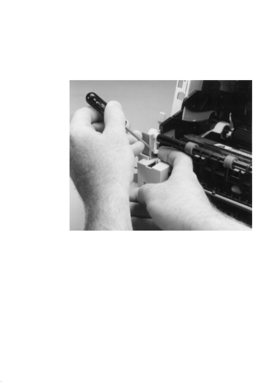
Pry in the tab at the lower end of the left exit roller bushing and
2
pull it inward.
Release the exit roller by rotating the tab up.
3
EN
www.GovTechMedia.com
Figure 39. Exit roller removal
Remove the exit roller by lifting up the left end; the right end
4
follows easily.
Internal assemblies
111
Page 2
D elive ry a ssembly
2
2
1
2
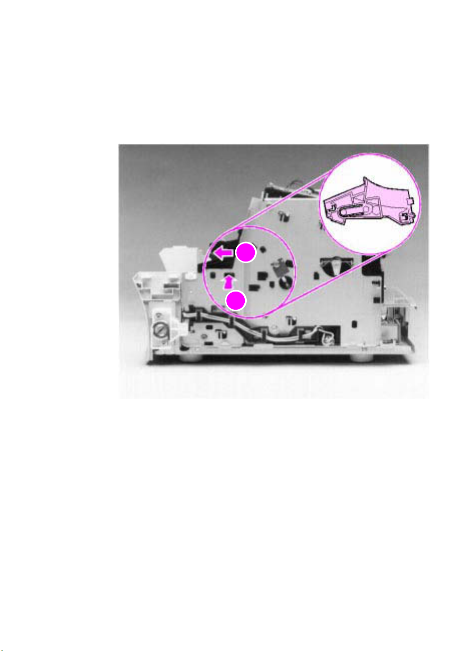
1 Remove all covers, the RFI shield, the printer door, and the exit
roller.
2 Remove the cartridge guide by pressing in the tab (callout 1) and
sliding the guide toward the front of the HP LaserJet 3100/3150
product (callout 2).
112 Removal and replacement
www.GovTechMedia.com
Figure 40. Delivery assembly removal (1 of 2)
EN
Page 3
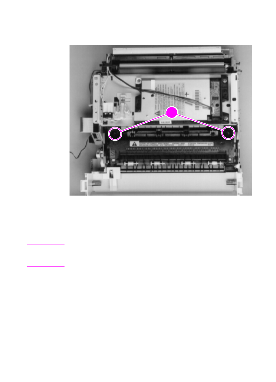
Use the magnetic screwdriver to remove the two (2) screws
2
1
3
(callout 1).
Note
EN
www.GovTechMedia.com
Figure 41. Delivery assembly removal (2 of 2)
Rotate the rear of the delivery assembly up and forward and lift it
4
out of the printer.
Upon reinstallation, the tabs on the front end of the delivery assembly
must fit under the sheet metal fuser plate below to correctly reseat the
delivery assembly.
Internal assemblies
113
Page 4
F user pre ssure pla te
2
2
3
2
1
2
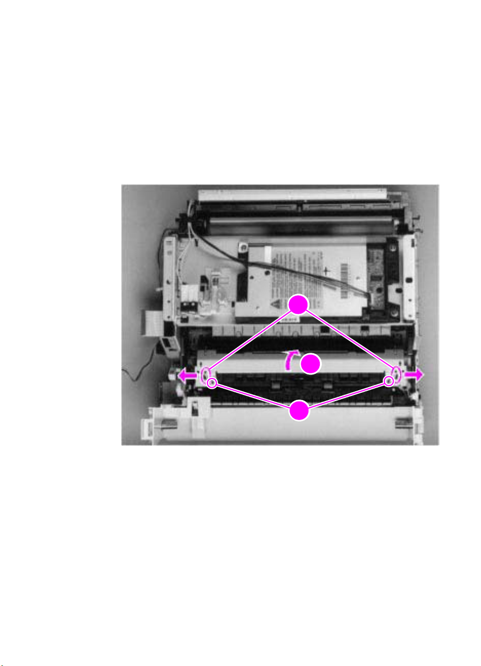
1 Remove all covers, the RFI shield, the printer door, the exit roller,
and the delivery assembly.
2 Remove the two (2) screws (callout 1).
3 Press the fuser plate retainer clips out (callout 2) to release the
pressure plate.
4 Rotate the plate around and toward the back (callout 3) and lift up
to remove it.
114 Removal and replacement
www.GovTechMedia.com
Figure 42. Fuser pressure plate removal
EN
Page 5

To r ei nstal l
The fuser pressure plate is held in place by four locking mechanisms
in each corner. Place the rear slits in the plate over the rear brackets
that hold the fusing assembly (callout 1). Lower the plate over the
retaining clips, pressing on both sides of the fuser pressure plate
(callout 2). It is important that the spring is placed over the positioning
pin (callout 3) because inadequate pressure will cause fusing
problems. Replace the screws.
EN
www.GovTechMedia.com
Figure 43. Fuser pressure plate replacement
Internal assemblies
115
Page 6

Front casing
2
1
1 Remove all covers, the RFI shield, and the printer door.
2 Remove the two (2) scre ws (callout 1) from the right hinge holder.
Note The lower screw on each of the hinge holders secures a small metal
grounding plate. Upon reinstallation, make sure the grounding plates
are in the correct position.
116 Removal and replacement
www.GovTechMedia.com
Figure 44. F ront casing removal
3 Lift the right hinge holder from the frame.
4 Repeat the procedure to remove the left hinge holder.
5 Lift the front of the product up slightly and press the tabs at the
bottom of the product to release the front casing.
6 Lift the front casing away from the product.
To r ei nstal l
Make sure that the paper path lev er hooks into the f ace-up/f ace-do wn
lever correctly.
EN
Page 7

Heating element
2
1
2
2
Remove all covers, the RFI shield, the printer door, the exit roller,
1
the delivery assembly, the fuser pressure plate, and the front
casing.
Disconnect the AC voltage to the heating element by releasing
2
the connector located on the ECU. Press down on the connector
release with the small flatblade screwdriver (callout 1). (Because
this is a small space, it is much easier to reach the connector with
a screwdriver.) Pull the connector straight out (callout 2).
EN
www.GovTechMedia.com
Figure 45. Heating element removal (1 of 2)
Remove the wire from the wire guides along the right side of the
3
printer.
Internal assemblies
117
Page 8

4 Disconnect the thermistor feedback connector (callout 1) in the
2
1
left, front side of the fusing assembly.
118 Removal and replacement
www.GovTechMedia.com
Figure 46. Heating element removal (2 of 2)
5 Lift the heating element out.
To r ei nstal l
Make sure the connectors are properly reattached and that the
thermistor feedback cable is routed behind the face-up/face-down
lever.
EN
Page 9

P ressure roller
2
2
2
1
Remove all covers, the RFI shield, the printer door, the exit roller,
1
the delivery assembly, the fuser pressure plate, the front casing,
and the heating element.
Remove the pressure roller guide by lifting the edge (callout 1)
2
and then rolling it gently backward (callout 2).
Note
Note
EN
www.GovTechMedia.com
Figure 47. Pressure roller guide removal
Lift the right end of the pressure roller up and out of the printer
3
chassis.
The right end of the pressure roller is greased.
The left side will follow easily with the pressure roller gear still
4
attached.
When reinstalling the pressure roller, apply a drop of pressure roller
grease to the grounding plate on the right end of the shaft. See Chapter
7, “Parts and diagrams,” for inf ormation about ordering pressure roller
grease.
Internal assemblies
119
Page 10

Face -up/ face -down le ver
1 Remove all covers, the RFI shield, the printer door, the exit roller,
the delivery assembly, the fuser pressure plate, the front casing,
the heating element, and the pressure roller.
2 Rotate the lever forward 90 degrees (past the spring) and pull it
straight out the front of the printer.
To r ei nstal l
1 Make sure the lever arm is on the left and is initially pointing
downward.
2 Pull the spring forward using needlenose pliers.
3 Slide the short, round tabs into the grooves on the separation
guide assembly. The machined ridges on the lever will face you.
4 Release the spring so it falls in place in front of the square tab.
Note You can tell when the lever is in place because there are two plastic
120 Removal and replacement
www.GovTechMedia.com
Figure 48. Face-up/face-down lever replacement
grooves that fit precisely in front of the exit rollers, and you should be
able to feel the spring’s release mechanism.
EN
Page 11

F user e xit roller a ssembly
2
2
2
1
Remove all covers, the RFI shield, the printer door, the exit roller,
1
the delivery assembly, the fuser pressure plate, the front casing,
the heating element, the pressure roller, and the face-up/facedown lever.
Remove the gear from the left end of the roller shaft by pressing
2
down on the catching mechanism with the small flatblade
screwdriver and pulling the gear away.
Remove the exit roller assembly by pressing the small, white tab
3
upward (callout 1) and rotating it around (callout 2).
Slide the exit roller assembly forward and out to the right of the
4
printer.
EN
www.GovTechMedia.com
Figure 49. Fuser exit roller assembly removal
Internal assemblies
121
 Loading...