

Page 1

HP LaserJet 1200 Printer
Service manual
Page 2

Copyright Information
© 2001 Hewlett-Packard
Company
All Rights Reserved.
Reproduction, adaptations, or
translation without prior written
permission is prohibited except
as allowed under copyright
laws.
Part number C7044-90906
First edition, March 2001
Printed in USA
Warranty
The information contained in
this document is subject to
change without notice.
Hewlett-Packard makes no
warranty of any kind with
respect to this information.
HEWLETT-PACKARD
SPECIFICALLY DISCLAIMS
THE IMPLIED WARRANTY OF
MERCHANTABILITY AND
FITNESS FOR A PARTICULAR
PURPOSE.
Hewlett-Packard shall not be
liable for any direct, indirect,
incidental, consequential, or
other damage alleged in
connection with the furnishing or
use of this information.
NOTICE TO U.S.
GOVERNMENT USERS:
RESTRICTED RIGHTS
COMMERCIAL COMPUTER
SOFTWARE: “Use, duplication,
or disclosure by the
Government is subject to
restrictions as set forth in
subparagraph (c) (1)(ii) of the
Rights in Technical Data Clause
at DFARS 52.227-7013.”
Trademark Credits
Microsoft, Windows, and MSDOS are U.S. registered
trademarks of Microsoft
Corporation.
TrueType is a U.S. trademark of
Apple Computer, Inc.
All other products mentioned
herein may be trademarks of
their respective companies.
Safety Information
WARNING!
Potential Shock Hazard
Always follow basic safety
precautions when using this
product to reduce risk of injury
from fire or electric shock.
1 Read and understand all
instructions in the user
guide.
2 Observe all warnings and
instructions marked on the
product.
3 Use only a grounded
electrical outlet when
connecting the
HP LaserJet 1200 printer
to a power source. If you
don’t know whether the
outlet is grounded, check
with a qualified electrician.
4 Do not touch the contacts
on the end of any of the
sockets on the
HP LaserJet 1200 printer.
Replace damaged cords
immediately.
5 Unplug this product from
wall outlets before
cleaning.
6 Do not install or use this
product near water or
when you are wet.
7 Install the product securely
on a stable surface.
8 Install the product in a
protected location where
no one can step on or trip
over the power cord and
the power cord will not be
damaged.
9 If the product does not
operate normally, see the
online user guide.
10 Refer all servicing
questions to qualified
personnel.
Information regarding FCC
Class B, Parts 15 and 68
requirements can be found in
the user guide.
Hewlett-Packard Company
11311 Chinden Boulevard
Boise, Idaho 83714 U.S.A.
Page 3

Contents
1 Product information
Chapter contents. . . . . . . . . . . . . . . . . . . . . . . . . . . . . . . . . . . . . . . . . . . . . . . . . 13
Introduction . . . . . . . . . . . . . . . . . . . . . . . . . . . . . . . . . . . . . . . . . . . . . . . . . . . . . 14
Hardware description . . . . . . . . . . . . . . . . . . . . . . . . . . . . . . . . . . . . . . . . . . 14
Firmware description . . . . . . . . . . . . . . . . . . . . . . . . . . . . . . . . . . . . . . . . . . 15
Product specifications. . . . . . . . . . . . . . . . . . . . . . . . . . . . . . . . . . . . . . . . . . 16
Model and serial numbers. . . . . . . . . . . . . . . . . . . . . . . . . . . . . . . . . . . . . . . . . . 19
Overview of printer . . . . . . . . . . . . . . . . . . . . . . . . . . . . . . . . . . . . . . . . . . . . . . . 20
Front and side view. . . . . . . . . . . . . . . . . . . . . . . . . . . . . . . . . . . . . . . . . . . . 20
Back and side view. . . . . . . . . . . . . . . . . . . . . . . . . . . . . . . . . . . . . . . . . . . . 21
Overview of optional copier/scanner. . . . . . . . . . . . . . . . . . . . . . . . . . . . . . . . . . 22
Top view . . . . . . . . . . . . . . . . . . . . . . . . . . . . . . . . . . . . . . . . . . . . . . . . . . . . 22
Warranty statement. . . . . . . . . . . . . . . . . . . . . . . . . . . . . . . . . . . . . . . . . . . . . . . 23
Extended warranty . . . . . . . . . . . . . . . . . . . . . . . . . . . . . . . . . . . . . . . . . . . . 24
Toner cartridge information . . . . . . . . . . . . . . . . . . . . . . . . . . . . . . . . . . . . . . . . 25
Refilled toner cartridges . . . . . . . . . . . . . . . . . . . . . . . . . . . . . . . . . . . . . . . 25
Recycling toner cartridges . . . . . . . . . . . . . . . . . . . . . . . . . . . . . . . . . . . . . . 25
2 Installation and operation
Chapter contents. . . . . . . . . . . . . . . . . . . . . . . . . . . . . . . . . . . . . . . . . . . . . . . . . 27
Operating environment . . . . . . . . . . . . . . . . . . . . . . . . . . . . . . . . . . . . . . . . . . . . 28
Identifying printer components . . . . . . . . . . . . . . . . . . . . . . . . . . . . . . . . . . . . . . 29
Printer control panel . . . . . . . . . . . . . . . . . . . . . . . . . . . . . . . . . . . . . . . . . . . 29
Control panel light patterns. . . . . . . . . . . . . . . . . . . . . . . . . . . . . . . . . . . . . . 30
Copier/scanner control panel . . . . . . . . . . . . . . . . . . . . . . . . . . . . . . . . . . . . 33
Selecting media. . . . . . . . . . . . . . . . . . . . . . . . . . . . . . . . . . . . . . . . . . . . . . . . . . 34
Selecting media to print . . . . . . . . . . . . . . . . . . . . . . . . . . . . . . . . . . . . . . . . 34
Selecting media to copy or scan . . . . . . . . . . . . . . . . . . . . . . . . . . . . . . . . 35
Loading media. . . . . . . . . . . . . . . . . . . . . . . . . . . . . . . . . . . . . . . . . . . . . . . . . . . 36
Loading media to print . . . . . . . . . . . . . . . . . . . . . . . . . . . . . . . . . . . . . . . . . 36
Loading media to copy or scan . . . . . . . . . . . . . . . . . . . . . . . . . . . . . . . . . . 37
Printer output paths . . . . . . . . . . . . . . . . . . . . . . . . . . . . . . . . . . . . . . . . . . . 38
3 Maintenance
Chapter contents. . . . . . . . . . . . . . . . . . . . . . . . . . . . . . . . . . . . . . . . . . . . . . . . . 39
Life expectancies of consumables . . . . . . . . . . . . . . . . . . . . . . . . . . . . . . . . . . . 40
EN Contents 3
Page 4

User-replaceable parts . . . . . . . . . . . . . . . . . . . . . . . . . . . . . . . . . . . . . . . . . . . . 40
Replacing the printer pickup roller . . . . . . . . . . . . . . . . . . . . . . . . . . . . . . . . 41
Replacing the printer separation pad . . . . . . . . . . . . . . . . . . . . . . . . . . . . . . 43
Replacing the copier/scanner separation pad . . . . . . . . . . . . . . . . . . . . . . . 45
Cleaning the equipment . . . . . . . . . . . . . . . . . . . . . . . . . . . . . . . . . . . . . . . . . . . 46
Cleaning the print path . . . . . . . . . . . . . . . . . . . . . . . . . . . . . . . . . . . . . . . . . 47
Cleaning the toner cartridge area. . . . . . . . . . . . . . . . . . . . . . . . . . . . . . . . . 48
Cleaning the printer pickup roller . . . . . . . . . . . . . . . . . . . . . . . . . . . . . . . . . 49
Cleaning the printer separation pad . . . . . . . . . . . . . . . . . . . . . . . . . . . . . . . 50
Copier/scanner recalibration. . . . . . . . . . . . . . . . . . . . . . . . . . . . . . . . . . . . . 51
Cleaning the scanner path . . . . . . . . . . . . . . . . . . . . . . . . . . . . . . . . . . . . . . 51
4 Operational overview
Chapter contents. . . . . . . . . . . . . . . . . . . . . . . . . . . . . . . . . . . . . . . . . . . . . . . . . 53
Basic functions . . . . . . . . . . . . . . . . . . . . . . . . . . . . . . . . . . . . . . . . . . . . . . . . . . 54
Formatter system . . . . . . . . . . . . . . . . . . . . . . . . . . . . . . . . . . . . . . . . . . . . . . . . 55
Control panel . . . . . . . . . . . . . . . . . . . . . . . . . . . . . . . . . . . . . . . . . . . . . . . . 56
Draft mode . . . . . . . . . . . . . . . . . . . . . . . . . . . . . . . . . . . . . . . . . . . . . . . . . . 56
MEt . . . . . . . . . . . . . . . . . . . . . . . . . . . . . . . . . . . . . . . . . . . . . . . . . . . . . . . . 56
Enhanced I/O . . . . . . . . . . . . . . . . . . . . . . . . . . . . . . . . . . . . . . . . . . . . . . . . 56
PJL overview . . . . . . . . . . . . . . . . . . . . . . . . . . . . . . . . . . . . . . . . . . . . . . . . 57
Printer functions . . . . . . . . . . . . . . . . . . . . . . . . . . . . . . . . . . . . . . . . . . . . . . . . . 58
Engine control unit/power system. . . . . . . . . . . . . . . . . . . . . . . . . . . . . . . . . 59
Image formation system . . . . . . . . . . . . . . . . . . . . . . . . . . . . . . . . . . . . . . . . 64
Printer paper-feed system . . . . . . . . . . . . . . . . . . . . . . . . . . . . . . . . . . . . . . 67
Jam detection . . . . . . . . . . . . . . . . . . . . . . . . . . . . . . . . . . . . . . . . . . . . . . . . 69
Optional copier/scanner . . . . . . . . . . . . . . . . . . . . . . . . . . . . . . . . . . . . . . . . . . . 71
Optical system . . . . . . . . . . . . . . . . . . . . . . . . . . . . . . . . . . . . . . . . . . . . . . . 71
Document pickup and feed systems. . . . . . . . . . . . . . . . . . . . . . . . . . . . . . . 71
Basic sequence of operation (formatter-to-printer). . . . . . . . . . . . . . . . . . . . 73
5 Removal and replacement
Chapter contents. . . . . . . . . . . . . . . . . . . . . . . . . . . . . . . . . . . . . . . . . . . . . . . . . 75
Removal and replacement strategy. . . . . . . . . . . . . . . . . . . . . . . . . . . . . . . . . . . 77
Required tools. . . . . . . . . . . . . . . . . . . . . . . . . . . . . . . . . . . . . . . . . . . . . . . . 77
Before performing service. . . . . . . . . . . . . . . . . . . . . . . . . . . . . . . . . . . . . . . 78
Toner cartridge . . . . . . . . . . . . . . . . . . . . . . . . . . . . . . . . . . . . . . . . . . . . . . . 78
Parts removal order . . . . . . . . . . . . . . . . . . . . . . . . . . . . . . . . . . . . . . . . . . . 79
Covers. . . . . . . . . . . . . . . . . . . . . . . . . . . . . . . . . . . . . . . . . . . . . . . . . . . . . . . . . 80
Left side cover . . . . . . . . . . . . . . . . . . . . . . . . . . . . . . . . . . . . . . . . . . . . . . . 80
Optional copier/scanner . . . . . . . . . . . . . . . . . . . . . . . . . . . . . . . . . . . . . . . . 81
Back cover . . . . . . . . . . . . . . . . . . . . . . . . . . . . . . . . . . . . . . . . . . . . . . . . . . 82
Right side cover . . . . . . . . . . . . . . . . . . . . . . . . . . . . . . . . . . . . . . . . . . . . . . 84
Top cover . . . . . . . . . . . . . . . . . . . . . . . . . . . . . . . . . . . . . . . . . . . . . . . . . . . 87
Control panel assembly . . . . . . . . . . . . . . . . . . . . . . . . . . . . . . . . . . . . . . . . 88
Front cover assembly . . . . . . . . . . . . . . . . . . . . . . . . . . . . . . . . . . . . . . . . . . 89
4 Contents EN
Page 5

Internal assemblies . . . . . . . . . . . . . . . . . . . . . . . . . . . . . . . . . . . . . . . . . . . . . . . 96
Transfer roller . . . . . . . . . . . . . . . . . . . . . . . . . . . . . . . . . . . . . . . . . . . . . . . . 96
Formatter . . . . . . . . . . . . . . . . . . . . . . . . . . . . . . . . . . . . . . . . . . . . . . . . . . . 97
Laser/scanner assembly. . . . . . . . . . . . . . . . . . . . . . . . . . . . . . . . . . . . . . . . 99
Fuser assembly . . . . . . . . . . . . . . . . . . . . . . . . . . . . . . . . . . . . . . . . . . . . . 101
Output rollers . . . . . . . . . . . . . . . . . . . . . . . . . . . . . . . . . . . . . . . . . . . . . . . 105
Motor. . . . . . . . . . . . . . . . . . . . . . . . . . . . . . . . . . . . . . . . . . . . . . . . . . . . . . 107
Solenoid . . . . . . . . . . . . . . . . . . . . . . . . . . . . . . . . . . . . . . . . . . . . . . . . . . . 108
Fan assembly . . . . . . . . . . . . . . . . . . . . . . . . . . . . . . . . . . . . . . . . . . . . . . . 110
Right plate assembly . . . . . . . . . . . . . . . . . . . . . . . . . . . . . . . . . . . . . . . . . 112
Pickup assembly. . . . . . . . . . . . . . . . . . . . . . . . . . . . . . . . . . . . . . . . . . . . . 114
Pickup roller shaft . . . . . . . . . . . . . . . . . . . . . . . . . . . . . . . . . . . . . . . . . . . . 117
Paper lift plate assembly. . . . . . . . . . . . . . . . . . . . . . . . . . . . . . . . . . . . . . . 119
Left plate assembly. . . . . . . . . . . . . . . . . . . . . . . . . . . . . . . . . . . . . . . . . . . 120
Bottom assemblies . . . . . . . . . . . . . . . . . . . . . . . . . . . . . . . . . . . . . . . . . . . . . . 121
ECU pan . . . . . . . . . . . . . . . . . . . . . . . . . . . . . . . . . . . . . . . . . . . . . . . . . . . 121
Paper-feed assembly . . . . . . . . . . . . . . . . . . . . . . . . . . . . . . . . . . . . . . . . . 125
6 Troubleshooting
Chapter contents. . . . . . . . . . . . . . . . . . . . . . . . . . . . . . . . . . . . . . . . . . . . . . . . 129
Basic troubleshooting . . . . . . . . . . . . . . . . . . . . . . . . . . . . . . . . . . . . . . . . . . . . 130
Errors. . . . . . . . . . . . . . . . . . . . . . . . . . . . . . . . . . . . . . . . . . . . . . . . . . . . . . . . . 132
Control panel light messages . . . . . . . . . . . . . . . . . . . . . . . . . . . . . . . . . . 132
Checking the toner cartridge . . . . . . . . . . . . . . . . . . . . . . . . . . . . . . . . . . . 137
Solving image-quality problems . . . . . . . . . . . . . . . . . . . . . . . . . . . . . . . . . 138
Solving paper feed problems. . . . . . . . . . . . . . . . . . . . . . . . . . . . . . . . . . . . . . . 146
Solving print paper feed problems . . . . . . . . . . . . . . . . . . . . . . . . . . . . . . . 146
Solving copying and scanning paper feed problems . . . . . . . . . . . . . . . . . 148
Functional checks . . . . . . . . . . . . . . . . . . . . . . . . . . . . . . . . . . . . . . . . . . . . . . . 149
Engine test . . . . . . . . . . . . . . . . . . . . . . . . . . . . . . . . . . . . . . . . . . . . . . . . . 149
Half-self-test functional check . . . . . . . . . . . . . . . . . . . . . . . . . . . . . . . . . . 150
Drum rotation functional check . . . . . . . . . . . . . . . . . . . . . . . . . . . . . . . . . 151
Heating element check . . . . . . . . . . . . . . . . . . . . . . . . . . . . . . . . . . . . . . . 152
High-voltage power supply check. . . . . . . . . . . . . . . . . . . . . . . . . . . . . . . . 153
Paper path check . . . . . . . . . . . . . . . . . . . . . . . . . . . . . . . . . . . . . . . . . . . . 155
Service mode functions. . . . . . . . . . . . . . . . . . . . . . . . . . . . . . . . . . . . . . . . . . . 156
NVRAM initialization . . . . . . . . . . . . . . . . . . . . . . . . . . . . . . . . . . . . . . . . . 156
PJL software commands . . . . . . . . . . . . . . . . . . . . . . . . . . . . . . . . . . . . . . 156
Troubleshooting tools . . . . . . . . . . . . . . . . . . . . . . . . . . . . . . . . . . . . . . . . . . . . 159
Internal reports . . . . . . . . . . . . . . . . . . . . . . . . . . . . . . . . . . . . . . . . . . . . . . 159
Repetitive image defect ruler . . . . . . . . . . . . . . . . . . . . . . . . . . . . . . . . . . . 161
Main wiring . . . . . . . . . . . . . . . . . . . . . . . . . . . . . . . . . . . . . . . . . . . . . . . . . 162
Locations of connectors . . . . . . . . . . . . . . . . . . . . . . . . . . . . . . . . . . . . . . . 164
Locations of LEDs, jumpers, and switches. . . . . . . . . . . . . . . . . . . . . . . . . 165
EN Contents 5
Page 6

7 Parts and diagrams
Chapter contents. . . . . . . . . . . . . . . . . . . . . . . . . . . . . . . . . . . . . . . . . . . . . . . . 167
Ordering parts and supplies . . . . . . . . . . . . . . . . . . . . . . . . . . . . . . . . . . . . . . . 168
Parts . . . . . . . . . . . . . . . . . . . . . . . . . . . . . . . . . . . . . . . . . . . . . . . . . . . . . . 168
Related documentation and software . . . . . . . . . . . . . . . . . . . . . . . . . . . . . 168
Consumables . . . . . . . . . . . . . . . . . . . . . . . . . . . . . . . . . . . . . . . . . . . . . . . 168
Accessories . . . . . . . . . . . . . . . . . . . . . . . . . . . . . . . . . . . . . . . . . . . . . . . . 169
How to use the parts lists and diagrams . . . . . . . . . . . . . . . . . . . . . . . . . . . . . . 170
Common hardware . . . . . . . . . . . . . . . . . . . . . . . . . . . . . . . . . . . . . . . . . . . . . . 170
Assembly locations . . . . . . . . . . . . . . . . . . . . . . . . . . . . . . . . . . . . . . . . . . . . . . 171
Printer trays & optional copier/scanner . . . . . . . . . . . . . . . . . . . . . . . . . . . 171
Covers. . . . . . . . . . . . . . . . . . . . . . . . . . . . . . . . . . . . . . . . . . . . . . . . . . . . . . . . 173
Internal assemblies . . . . . . . . . . . . . . . . . . . . . . . . . . . . . . . . . . . . . . . . . . . . . . 175
Internal components (1 of 2). . . . . . . . . . . . . . . . . . . . . . . . . . . . . . . . . . . . 175
Internal components (2 of 2). . . . . . . . . . . . . . . . . . . . . . . . . . . . . . . . . . . . 177
Electrical components. . . . . . . . . . . . . . . . . . . . . . . . . . . . . . . . . . . . . . . . . 179
Paper pickup assembly (1 of 2) . . . . . . . . . . . . . . . . . . . . . . . . . . . . . . . . . 181
Paper pickup assembly (2 of 2) . . . . . . . . . . . . . . . . . . . . . . . . . . . . . . . . . 183
Fuser assembly . . . . . . . . . . . . . . . . . . . . . . . . . . . . . . . . . . . . . . . . . . . . . 185
Alphabetical parts list . . . . . . . . . . . . . . . . . . . . . . . . . . . . . . . . . . . . . . . . . . . . 187
Numerical parts list . . . . . . . . . . . . . . . . . . . . . . . . . . . . . . . . . . . . . . . . . . . . . . 191
6 Contents EN
Page 7

Figures
Figure 1. Model and serial number labels . . . . . . . . . . . . . . . . . . . . . . . . . . . . . . 19
Figure 2. Front and side view . . . . . . . . . . . . . . . . . . . . . . . . . . . . . . . . . . . . . . . 20
Figure 3. Back and side view. . . . . . . . . . . . . . . . . . . . . . . . . . . . . . . . . . . . . . . . 21
Figure 4. Top view. . . . . . . . . . . . . . . . . . . . . . . . . . . . . . . . . . . . . . . . . . . . . . . . 22
Figure 5. Dimensions of printer . . . . . . . . . . . . . . . . . . . . . . . . . . . . . . . . . . . . . . 28
Figure 6. Dimensions of printer with optional copier/scanner . . . . . . . . . . . . . . . 28
Figure 7. Printer control panel . . . . . . . . . . . . . . . . . . . . . . . . . . . . . . . . . . . . . . . 29
Figure 8. Light status legend . . . . . . . . . . . . . . . . . . . . . . . . . . . . . . . . . . . . . . . . 30
Figure 9. Copier/scanner control panel . . . . . . . . . . . . . . . . . . . . . . . . . . . . . . . . 33
Figure 10. Scanning a business card . . . . . . . . . . . . . . . . . . . . . . . . . . . . . . . . . . 37
Figure 11. Output bin. . . . . . . . . . . . . . . . . . . . . . . . . . . . . . . . . . . . . . . . . . . . . . . 38
Figure 12. Straight-through output door. . . . . . . . . . . . . . . . . . . . . . . . . . . . . . . . . 38
Figure 13. Basic configuration . . . . . . . . . . . . . . . . . . . . . . . . . . . . . . . . . . . . . . . . 54
Figure 14. Printer unit functional block diagram . . . . . . . . . . . . . . . . . . . . . . . . . . 58
Figure 15. ECU loads . . . . . . . . . . . . . . . . . . . . . . . . . . . . . . . . . . . . . . . . . . . . . . 60
Figure 16. Overview of laser/scanner operation . . . . . . . . . . . . . . . . . . . . . . . . . . 61
Figure 17. High-voltage power supply circuit. . . . . . . . . . . . . . . . . . . . . . . . . . . . . 63
Figure 18. Image formation block diagram . . . . . . . . . . . . . . . . . . . . . . . . . . . . . . 64
Figure 19. Printer path. . . . . . . . . . . . . . . . . . . . . . . . . . . . . . . . . . . . . . . . . . . . . . 68
Figure 20. Solenoid, photosensors, and switches . . . . . . . . . . . . . . . . . . . . . . . . . 70
Figure 21. Copier/scanner path . . . . . . . . . . . . . . . . . . . . . . . . . . . . . . . . . . . . . . 72
Figure 22. General timing diagram . . . . . . . . . . . . . . . . . . . . . . . . . . . . . . . . . . . 74
Figure 23. Removing the toner cartridge. . . . . . . . . . . . . . . . . . . . . . . . . . . . . . . . 78
Figure 24. Removing the left side cover . . . . . . . . . . . . . . . . . . . . . . . . . . . . . . . . 80
Figure 25. Removing the optional copier/scanner. . . . . . . . . . . . . . . . . . . . . . . . . 81
Figure 26. Removing the back cover (1 of 2). . . . . . . . . . . . . . . . . . . . . . . . . . . . . 82
Figure 27. Removing the back cover (2 of 2). . . . . . . . . . . . . . . . . . . . . . . . . . . . . 83
Figure 28. Removing the right side cover (1 of 3) . . . . . . . . . . . . . . . . . . . . . . . . . 84
Figure 29. Removing the right side cover (2 of 3) . . . . . . . . . . . . . . . . . . . . . . . . . 85
Figure 30. Removing the right side cover (3 of 3) . . . . . . . . . . . . . . . . . . . . . . . . . 86
Figure 31. Removing the top cover . . . . . . . . . . . . . . . . . . . . . . . . . . . . . . . . . . . . 87
Figure 32. Removing the control panel . . . . . . . . . . . . . . . . . . . . . . . . . . . . . . . . . 88
Figure 33. Removing the front cover (1 of 2). . . . . . . . . . . . . . . . . . . . . . . . . . . . . 89
Figure 34. Removing the front cover (2 of 2). . . . . . . . . . . . . . . . . . . . . . . . . . . . . 90
Figure 35. Removing the toner cartridge door (1 of 2). . . . . . . . . . . . . . . . . . . . . . 91
Figure 36. Removing the toner cartridge door (2 of 2). . . . . . . . . . . . . . . . . . . . . . 92
Figure 37. Removing the front guide assembly (1 of 3). . . . . . . . . . . . . . . . . . . . . 93
Figure 38. Removing the front guide assembly (2 of 3). . . . . . . . . . . . . . . . . . . . . 94
Figure 39. Removing the front guide assembly (3 of 3). . . . . . . . . . . . . . . . . . . . . 95
Figure 40. Removing the transfer roller . . . . . . . . . . . . . . . . . . . . . . . . . . . . . . . . . 96
Figure 41. Removing the formatter (1 of 2) . . . . . . . . . . . . . . . . . . . . . . . . . . . . . . 97
EN Figures 7
Page 8

Figure 42. Removing the formatter (2 of 2) . . . . . . . . . . . . . . . . . . . . . . . . . . . . . . 98
Figure 43. Removing the laser/scanner (1 of 2) . . . . . . . . . . . . . . . . . . . . . . . . . . 99
Figure 44. Removing the laser/scanner (2 of 2) . . . . . . . . . . . . . . . . . . . . . . . . . 100
Figure 45. Removing the fuser assembly (1 of 4) . . . . . . . . . . . . . . . . . . . . . . . . 101
Figure 46. Removing the fuser assembly (2 of 4) . . . . . . . . . . . . . . . . . . . . . . . . 102
Figure 47. Removing the fuser assembly (3 of 4) . . . . . . . . . . . . . . . . . . . . . . . . 103
Figure 48. Removing the fuser assembly (4 of 4) . . . . . . . . . . . . . . . . . . . . . . . . 104
Figure 49. Removing the output rollers (1 of 2). . . . . . . . . . . . . . . . . . . . . . . . . . 105
Figure 50. Removing the output rollers (2 of 2). . . . . . . . . . . . . . . . . . . . . . . . . . 106
Figure 51. Removing the motor . . . . . . . . . . . . . . . . . . . . . . . . . . . . . . . . . . . . . . 107
Figure 52. Removing the solenoid (1 of 2). . . . . . . . . . . . . . . . . . . . . . . . . . . . . . 108
Figure 53. Removing the solenoid (2 of 2). . . . . . . . . . . . . . . . . . . . . . . . . . . . . . 109
Figure 54. Removing the fan (1 of 2). . . . . . . . . . . . . . . . . . . . . . . . . . . . . . . . . . 110
Figure 55. Removing the fan (2 of 2). . . . . . . . . . . . . . . . . . . . . . . . . . . . . . . . . . 111
Figure 56. Removing the right plate assembly (1 of 2) . . . . . . . . . . . . . . . . . . . . 112
Figure 57. Removing the right plate assembly (2 of 2) . . . . . . . . . . . . . . . . . . . . 113
Figure 58. Removing the pickup assembly (1 of 3) . . . . . . . . . . . . . . . . . . . . . . . 114
Figure 59. Removing the pickup assembly (2 of 3) . . . . . . . . . . . . . . . . . . . . . . . 115
Figure 60. Removing the pickup assembly (3 of 3) . . . . . . . . . . . . . . . . . . . . . . . 116
Figure 61. Removing the pickup roller shaft (1 of 2) . . . . . . . . . . . . . . . . . . . . . . 117
Figure 62. Removing the pickup roller shaft (2 of 2) . . . . . . . . . . . . . . . . . . . . . . 118
Figure 63. Removing the paper lift plate assembly . . . . . . . . . . . . . . . . . . . . . . . 119
Figure 64. Removing the left plate assembly. . . . . . . . . . . . . . . . . . . . . . . . . . . . 120
Figure 65. Removing the ECU pan (1 of 4) . . . . . . . . . . . . . . . . . . . . . . . . . . . . . 121
Figure 66. Removing the ECU pan (2 of 4) . . . . . . . . . . . . . . . . . . . . . . . . . . . . . 122
Figure 67. Removing the ECU pan (3 of 4) . . . . . . . . . . . . . . . . . . . . . . . . . . . . . 123
Figure 68. Removing the ECU pan (4 of 4) . . . . . . . . . . . . . . . . . . . . . . . . . . . . . 124
Figure 69. Removing the paper-feed assembly (1 of 4) . . . . . . . . . . . . . . . . . . . 125
Figure 70. Removing the paper-feed assembly (2 of 4) . . . . . . . . . . . . . . . . . . . 126
Figure 71. Removing the paper-feed mechanism (3 of 4) . . . . . . . . . . . . . . . . . . 127
Figure 72. Removing the paper-feed mechanism (4 of 4) . . . . . . . . . . . . . . . . . . 128
Figure 73. Control panel location. . . . . . . . . . . . . . . . . . . . . . . . . . . . . . . . . . . . . 132
Figure 74. Engine test switch. . . . . . . . . . . . . . . . . . . . . . . . . . . . . . . . . . . . . . . . 149
Figure 75. Locating connectors for the heating element check . . . . . . . . . . . . . . 152
Figure 76. Toner cartridge high-voltage connection points (right side) . . . . . . . . 153
Figure 77. Toner cartridge high-voltage connection points (left side) . . . . . . . . . 153
Figure 78. High-voltage connector assembly (right side) . . . . . . . . . . . . . . . . . . 154
Figure 79. High-voltage connector assembly (left side). . . . . . . . . . . . . . . . . . . . 154
Figure 80. Overriding SW301 . . . . . . . . . . . . . . . . . . . . . . . . . . . . . . . . . . . . . . . 155
Figure 81. Self-test page . . . . . . . . . . . . . . . . . . . . . . . . . . . . . . . . . . . . . . . . . . . 160
Figure 82. Repetitive image defect ruler . . . . . . . . . . . . . . . . . . . . . . . . . . . . . . . 161
Figure 83. Main wiring (1 of 2). . . . . . . . . . . . . . . . . . . . . . . . . . . . . . . . . . . . . . . 162
Figure 84. Main wiring (2 of 2). . . . . . . . . . . . . . . . . . . . . . . . . . . . . . . . . . . . . . . 163
Figure 85. Locations of printer connectors . . . . . . . . . . . . . . . . . . . . . . . . . . . . . 164
Figure 86. Locations of copier/scanner connectors. . . . . . . . . . . . . . . . . . . . . . . 164
Figure 87. Locations of LEDs, jumpers, and switches. . . . . . . . . . . . . . . . . . . . . 165
Figure 88. Assembly locations. . . . . . . . . . . . . . . . . . . . . . . . . . . . . . . . . . . . . . . 171
8 Figures EN
Page 9

Figure 89. Covers . . . . . . . . . . . . . . . . . . . . . . . . . . . . . . . . . . . . . . . . . . . . . . . . 173
Figure 90. Internal components (1 of 2). . . . . . . . . . . . . . . . . . . . . . . . . . . . . . . . 175
Figure 91. Internal components (2 of 2). . . . . . . . . . . . . . . . . . . . . . . . . . . . . . . . 177
Figure 92. Electrical components . . . . . . . . . . . . . . . . . . . . . . . . . . . . . . . . . . . . 179
Figure 93. Paper pickup assembly (1 of 2) . . . . . . . . . . . . . . . . . . . . . . . . . . . . . 181
Figure 94. Paper pickup assembly (2 of 2) . . . . . . . . . . . . . . . . . . . . . . . . . . . . . 183
Figure 95. Fuser assembly . . . . . . . . . . . . . . . . . . . . . . . . . . . . . . . . . . . . . . . . . 185
EN Figures 9
Page 10

10 Figures EN
Page 11

Tables
Table 1. Physical specifications . . . . . . . . . . . . . . . . . . . . . . . . . . . . . . . . . . . . . 16
Table 2. Environmental specifications . . . . . . . . . . . . . . . . . . . . . . . . . . . . . . . 16
Table 3. Power specifications . . . . . . . . . . . . . . . . . . . . . . . . . . . . . . . . . . . . . . 17
Table 4. Performance of HP LaserJet 1200 printer . . . . . . . . . . . . . . . . . . . . . . 17
Table 5. Performance of optional copier/scanner. . . . . . . . . . . . . . . . . . . . . . . . 17
Table 6. Print operating acoustical emissions specifications . . . . . . . . . . . . . . . 18
Table 7. Copy operating acoustical emissions specifications. . . . . . . . . . . . . . . 18
Table 8. Skew specifications . . . . . . . . . . . . . . . . . . . . . . . . . . . . . . . . . . . . . . . 18
Table 9. Control panel light messages . . . . . . . . . . . . . . . . . . . . . . . . . . . . . . . . 30
Table 10. Media types . . . . . . . . . . . . . . . . . . . . . . . . . . . . . . . . . . . . . . . . . . . . . 34
Table 11. Life expectancies of consumables . . . . . . . . . . . . . . . . . . . . . . . . . . . . 40
Table 12. Basic sequence of operation . . . . . . . . . . . . . . . . . . . . . . . . . . . . . . . . 73
Table 13. Basic troubleshooting . . . . . . . . . . . . . . . . . . . . . . . . . . . . . . . . . . . . 130
Table 14. Control panel lights legend. . . . . . . . . . . . . . . . . . . . . . . . . . . . . . . . . 132
Table 15. Control panel light messages . . . . . . . . . . . . . . . . . . . . . . . . . . . . . . . 133
Table 16. Fatal error secondary messages . . . . . . . . . . . . . . . . . . . . . . . . . . . . 134
Table 17. Solving print image-quality problems . . . . . . . . . . . . . . . . . . . . . . . . . 138
Table 18. Solving copying and scanning image-quality problems . . . . . . . . . . . 143
Table 19. Solving print paper feed problems . . . . . . . . . . . . . . . . . . . . . . . . . . . 146
Table 20. Solving copying and scanning paper feed problems . . . . . . . . . . . . . 148
Table 21. NVRAM PJL factory variables . . . . . . . . . . . . . . . . . . . . . . . . . . . . . . 157
Table 22. Switch functions . . . . . . . . . . . . . . . . . . . . . . . . . . . . . . . . . . . . . . . . . 165
Table 23. Technical support websites . . . . . . . . . . . . . . . . . . . . . . . . . . . . . . . . 168
Table 24. Accessories . . . . . . . . . . . . . . . . . . . . . . . . . . . . . . . . . . . . . . . . . . . . 169
Table 25. Common fasteners . . . . . . . . . . . . . . . . . . . . . . . . . . . . . . . . . . . . . . . 170
Table 26. Printer trays and optional copier/scanner. . . . . . . . . . . . . . . . . . . . . . 172
Table 27. External covers. . . . . . . . . . . . . . . . . . . . . . . . . . . . . . . . . . . . . . . . . . 174
Table 28. Internal components (1 of 2). . . . . . . . . . . . . . . . . . . . . . . . . . . . . . . . 176
Table 29. Internal components (2 of 2). . . . . . . . . . . . . . . . . . . . . . . . . . . . . . . . 178
Table 30. Electrical components . . . . . . . . . . . . . . . . . . . . . . . . . . . . . . . . . . . . 180
Table 31. Paper pickup assembly (1 of 2) . . . . . . . . . . . . . . . . . . . . . . . . . . . . . 182
Table 32. Paper pickup assembly (2 of 2) . . . . . . . . . . . . . . . . . . . . . . . . . . . . . 184
Table 33. Fuser assembly . . . . . . . . . . . . . . . . . . . . . . . . . . . . . . . . . . . . . . . . . 186
Table 34. Alphabetical parts list . . . . . . . . . . . . . . . . . . . . . . . . . . . . . . . . . . . . . 187
Table 35. Numerical parts list. . . . . . . . . . . . . . . . . . . . . . . . . . . . . . . . . . . . . . . 191
EN Tables 11
Page 12

12 Chapter - Tables EN
Page 13

1Product information
Chapter contents
Introduction . . . . . . . . . . . . . . . . . . . . . . . . . . . . . . . . . . . . . . 14
Hardware description . . . . . . . . . . . . . . . . . . . . . . . . . .14
Firmware description . . . . . . . . . . . . . . . . . . . . . . . . . .15
Product specifications . . . . . . . . . . . . . . . . . . . . . . . . . . . . . .16
Model and serial numbers . . . . . . . . . . . . . . . . . . . . . . . . . . . 19
Overview of printer. . . . . . . . . . . . . . . . . . . . . . . . . . . . . . . . . 20
Front and side view . . . . . . . . . . . . . . . . . . . . . . . . . . .20
Back and side view. . . . . . . . . . . . . . . . . . . . . . . . . . . . 21
Overview of optional copier/scanner . . . . . . . . . . . . . . . . . . .22
Top view. . . . . . . . . . . . . . . . . . . . . . . . . . . . . . . . . . . . 22
Warranty statement . . . . . . . . . . . . . . . . . . . . . . . . . . . . . . . . 23
Extended warranty . . . . . . . . . . . . . . . . . . . . . . . . . . . .24
Toner cartridge information . . . . . . . . . . . . . . . . . . . . . . . . . .25
Refilled toner cartridges . . . . . . . . . . . . . . . . . . . . . . . .25
Recycling toner cartridges . . . . . . . . . . . . . . . . . . . . . . 25
EN Chapter contents 13
Page 14

Introduction
The HP LaserJet 1200 printer is designed to:
l Print—Print documents easily with the laser-quality you have
With the optional copier/scanner, you can:
l Copy—Make superior laser-quality copies. With the software,
l Scan—Scan important documents to create electronic files.
Hardware description
The printer provides 1200 dot-per-inch (dpi) printing. The optional
copier/scanner scans at 600 dpi/ 24-bits per pixel (bpp) and contains
a document feeder that holds up to 30 pages.
The printer prints 15 pages per minute (ppm) on letter-size paper or
14 ppm on A4. With 1200 dpi printing resolution, the printer has
exceptional text and graphics print quality. The sim p le co nt ro l panel
and improved paper handling make this pr od u ct ver y ea sy to use.
The printer’s main input tray has a 250-sheet capacity for continu ous,
multiple-page printing. Manual, single-sheet printing is possible
through the priority input tray. Both trays are center-justified for all
supported paper sizes. The printer output bin holds up to 125 sheets.
come to expect from an HP LaserJet printer.
you can make up to 99 copies of a 30-p age original. You can also
enlarge, reduce, adjust contrast, and collate.
The printer has a very fast first-page-out, at less than 10 seconds.
The formatter board contains 8 MB of ROM, 8 MB of RAM, and an
embedded 32-bit Coldfire V3 processor. There is one DIMM slot
available for DIMM expansion (supporting an 8 MB, 16 MB, 32 MB, or
64 MB DIMM).
The printer engine has a 1,000 average (10,000 peak) page-permonth duty cycle. For the printer, the standard to ner life is 2,500
pages, and the high capacity toner life is 3,500 pages.
14 Chapter 1 - Product information EN
Page 15

Firmware description
The firmware in the printer includes:
l Enhanced PCL 6 with status readback
l 80 TrueType™ fonts, plus Cyrillic, Greek, Hebrew, and Arabic
l Pixel placement, mosaic characters
l Memory Enhancement technology (MEt) with hardware
compression/decompression
The printer firmware also has REt and EconoMode functi onality. Scan
capability includes 600 dpi and 24-bit color.
EN Introduction 15
Page 16

Product specifications
Table 1. Physical specifications
Category Specification
Height 253 mm (10.0 inches) without optional copier/
scanner
416 mm (16.4 inches) with optional copier/
scanner
Depth 486 mm (19.1 inches)
Width 415 mm (16.3 inches)
Weight (cartridge
installed)
Table 2. Environmental specifications
Category Specification
Operating
environment (printer
plugged into an AC
outlet)
Storage environment
(printer not plugged
into an AC outlet)
7.3 kg (16.1 lb) without optional copier/scanner
8.7 kg (19.2 lb) with optional copier/scanner
l Temperature: 15° to 32.5° C (59° to 90.5° F)
l Humidity: 20% to 80% relative humidity
(no condensation)
l Temperature: 0° to 40° C (32° to 104° F)
l Humidity: 10% to 90% relative humidity
(no condensation)
16 Chapter 1 - Product information EN
Page 17

Table 3. Power specifications
Category Specification
Power
requirements
l 110 Vac (± 12%), 60 (± 3) Hz; 127 Vac
(± 12%), 60 (± 3) Hz
-Or-
l 220 Vac (± 12%), 50/60 (± 3) Hz
l 240 Vac (± 12%), 50 (± 3) Hz
Note Power sources are not
interchangeable.
Power consumption
(in continuous copy
mode)
Power consumption
(idle)
Power consumption
(off)
Minimum
recommended circuit
capacity
285 W
7 W
0 W
4.5 A at 115 V
2.3 A at 230 V
Table 4. Performance of HP LaserJet 1200 printer
Category Specification
Print resolution 1200 dpi
Print speed 15 ppm (Letter)
14 ppm (A4)
Table 5. Performance of optional copier/scanner
Category Specification
Scan resolution 600 dpi optical, with 256 levels of gray and 24-bit
color
Copy speed 12 ppm
EN Introduction 17
Page 18

Table 6. Print operating acoustical emissi ons specifications
Category Specification
Sound Power Level,
L
(1 bel = 10 decibels)
WAd
Sound Pressure Level,
(operator position)
L
pAm
Sound Pressure Level,
L
(bystander position)
pAm
6.1 B
56 dB
48 dB
Table 7. Copy operating acoustical emissions specifications
Category Specification
Sound Power Level,
(1 bel = 10 decibels)
L
WAd
Sound Pressure Level,
L
(operator position)
pAm
Sound Pressure Level,
L
(bystander position)
pAm
6.4 B
60 dB
50 dB
Table 8. Skew specifications
Category Specification
Print skew—left
0.8% (2 mm over 250 mm in length) for
cut-sheet media)
1.5% (3.3 mm over 220 mm in length) for
cut-sheet media
0.87 (1.65 mm ov er 190 mm in width) for
cut-sheet media
Print skew—right
1.5% (3.3 mm over 220 mm in width) for
envelopes, postcards, A5, and cut-sheet
media
Cut-sheet leading
edge skew
Scan skew
0.87% (1.6 mm over 190 mm in width)
1.2%
18 Chapter 1 - Product information EN
Page 19
Model and serial numbers
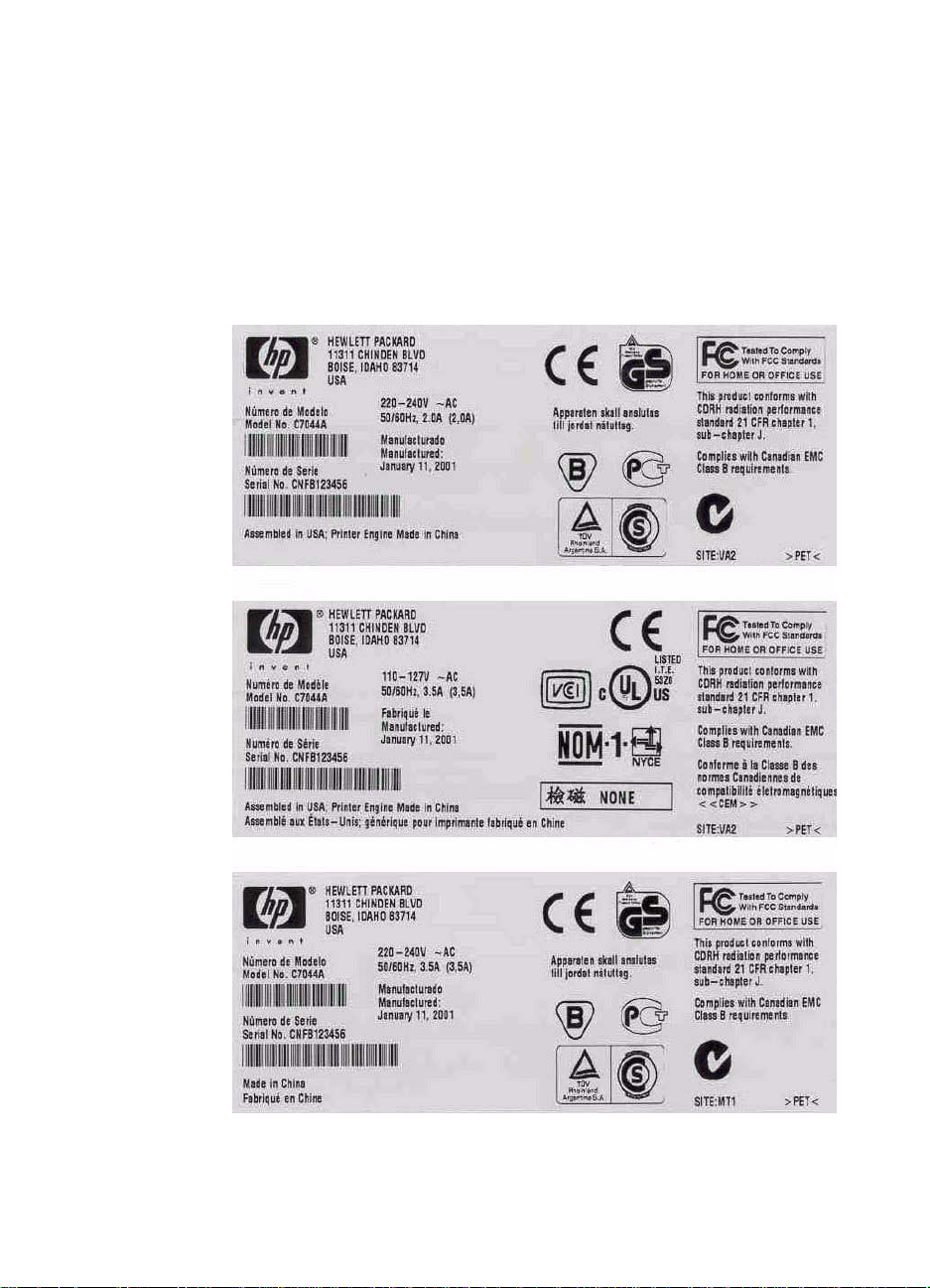
The model number and serial number are listed on an identi fication
label located on the inside of the toner cartridge door.
The serial number contains inf ormation about the country of origin,
revision level, production code, and production number of the printer.
The label also contains power rating and regulatory information.
Figure 1. Model and serial number labels
EN Model and serial numbers 19
Page 20
Overview of printer
Front and side view
1
8
7
6
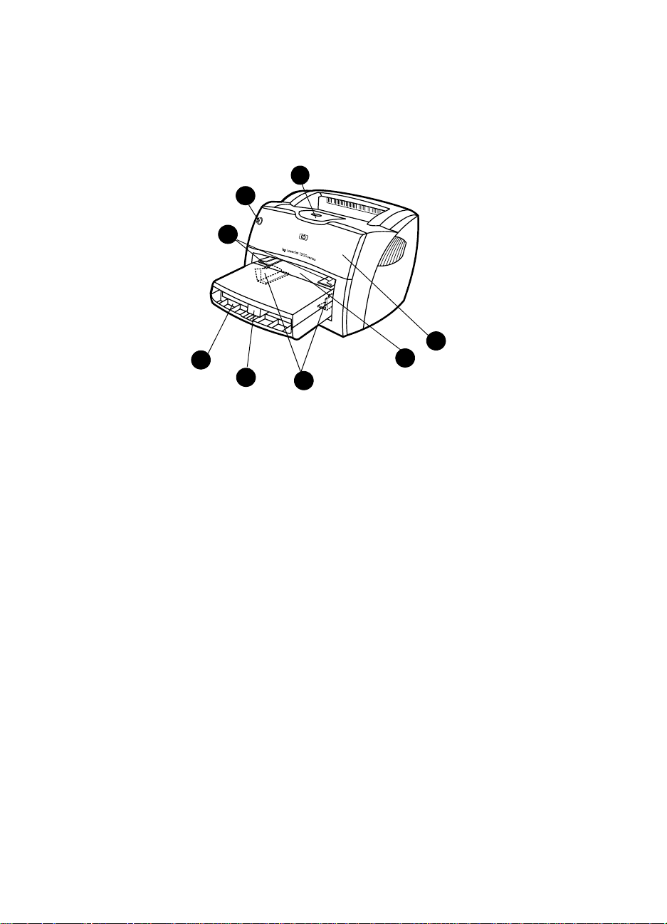
Figure 2. Front and side view
1 Printer control pan el
2
3
4
5
2 Long media extension (output bin)
3 Toner cartridge door
4 Priority input tray
5 Side media guides for the main input tray
6 Long media support for the main input tray
7 Main input tray
8 Side media guides for the priority input tray
20 Chapter 1 - Product information EN
Page 21
Back and side view
16
15
14
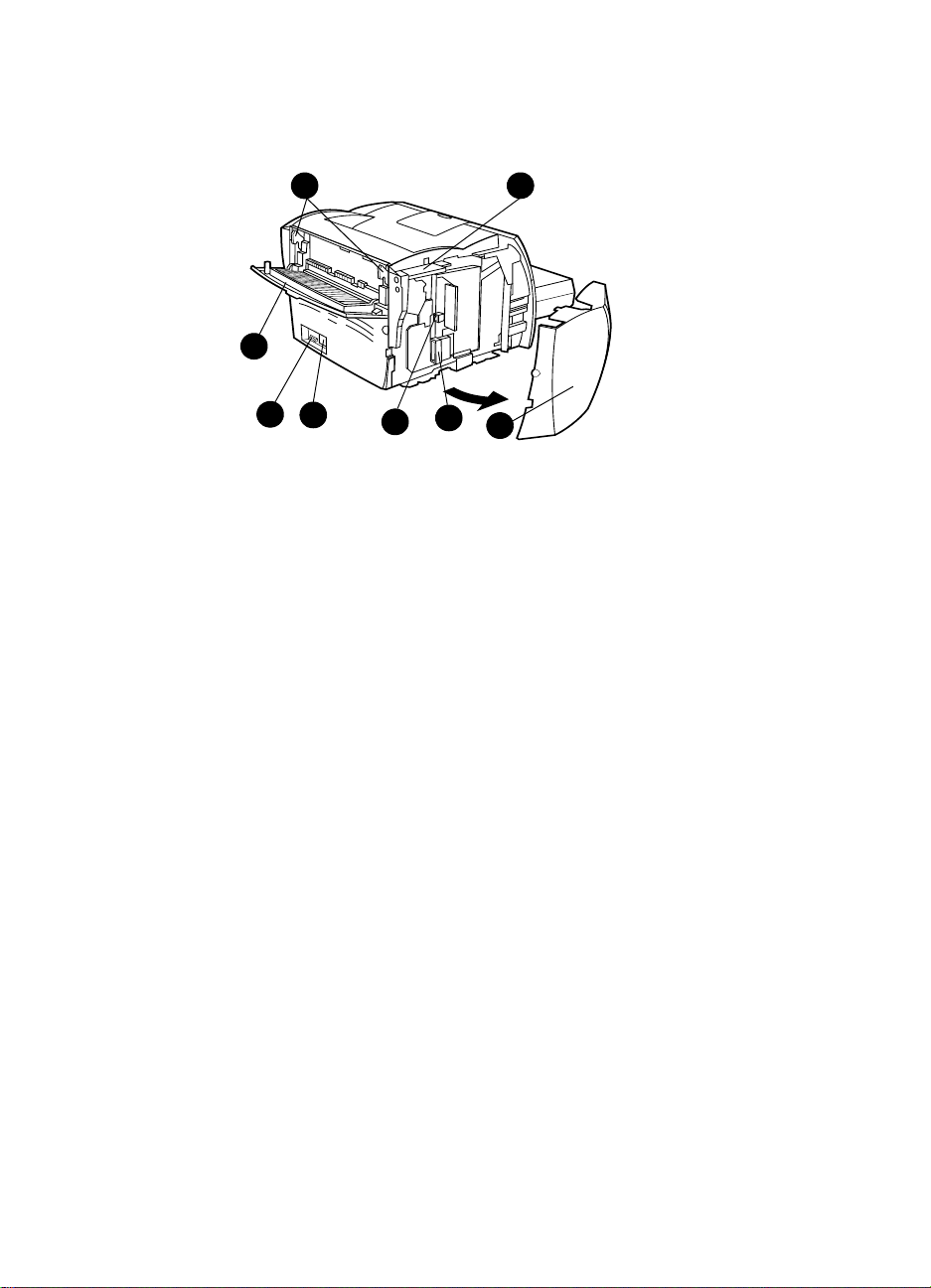
Figure 3. Back and side view
9 Fuser release levers
10 Connection to optional copier/scanner
11 Left side cover
13
12
109
11
12 Parallel port
13 USB port
14 Power receptacle
15 Power switch (220-240 volt printers)
16 Straight-through output door
EN Overview of printer 21
Page 22
Overview of optional copier/scanner
Top view
1
2
8
7
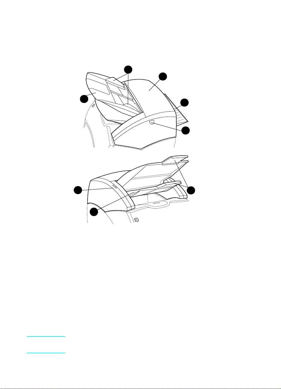
Figure 4. Top view
1 Media input tray guides
2 Copier/scanner door
3 Straight-through output door
3
4
5
6
4 Copier/scanne r do or rele a se bu tt on
5 Long media extensions
6 Media output bin
7 Copier/scanner control panel
8 Media input tray
Note See “Optional copier/scanner” on page 81 for more information about
removing the optional copier/scanner from the printer.
22 Chapter 1 - Product information EN
Page 23

Warranty statement
DURATION OF WARRANTY: One year from date of purchase.
1. HP warrants to you, the end-user customer, that HP hardware, accessories, and
supplies, will be free from defects in materials and workmanship after the date of
purchase, for the period specified above. If HP receives notice of such defects
during the warranty period, HP will, at its option, either repair or replace products
which prove to be defective . Replace ment products ma y be ei ther ne w or li k e-ne w.
2. HP warrants to you that HP software will not fail to execute its programming
instructions after the date of purchase, for the period specified above, due to
defects in material and workmanship when properly installed and used. If
HP receives notice of such defects during the warranty period, HP will replace
software media which does not execute its programming instructions due to such
defects.
3. HP does not warrant that the operation of HP products will be uninterrupted or
error free. If HP is unable, within a reasonable time, to repair or replace any
product to a condition as warranted, you will be entitled to a refund of the
purchase price upon prompt return of the product.
4. HP products may contain remanufactured parts equivalent to new in performance
or may have been subject to incidental use.
5. Warranty does not apply to defects resulting from (a) improper or inadequate
maintenance or calibration, (b) software, interfacing, parts, or supplies not
supplied by HP, (c) unauthorized modification or misuse, (d) operation outside of
the published environmental specifications for the product, or (d) improper site
preparation or maintenance.
6. HP MAKES NO OTHER EXPRESS WARRANTY OR CONDITION WHETHER
WRITTEN OR ORAL. TO THE EXTENT ALLOWED BY LOCAL LAW, ANY
IMPLIED WARRANTY OR CONDITION OR MERCHANTABILITY,
SATISFACTORY QUALITY, OR FITNESS FOR A PARTICULAR PURPOSE IS
LIMITED TO THE DURATION OF THE EXPRESS WARRANTY SET FORTH
ABOVE. Some countries, states, or provinces do not allow limitations on the
duration of an implied warranty, so the above limitation or exclusion might not
apply to you. This warranty gives you specific legal rights and you might also have
other rights that vary from country to country, state to state, or province to
province.
EN Warranty statement 23
Page 24

7. TO THE EXTENT ALLOWED BY LOCAL LAW, THE REMEDIES IN THIS
WARRANTY STATEMENT ARE YOUR SOLE AND EXCLUSIVE REMEDIES.
EXCEPT AS INDICATED ABOVE, IN NO EVENT WILL HP OR ITS SUPPLIERS
BE LIABLE FOR LOSS OF DATA OR FOR DIRECT, SPECIAL, INCIDENTAL,
CONSEQUENTIAL (INCLUDING LOST PROFIT OR DATA), OR OTHER
DAMAGE, WHETHER BASED IN CONTRACT, TORT, OR OTHERWISE. Some
countries, states, or provinces do not allow the exclusion or limitation of inciden tal
or consequential damages, so the above limitation or exclusion may not apply to
you.
FOR CONSUMER TRANSACTIONS IN AUSTRALIA AND NEW ZEALAND, THE
WARRANTY TERMS CONTAINED IN THIS STATEMENT, EXCEPT TO THE
EXTENT LAWFULLY PERMITTED, DO NOT EXCLUDE, RESTRICT OR
MODIFY AND ARE IN ADDITION TO THE MANDATORY STATUTORY RIGHTS
APPLICABLE TO THE SALE OF THIS PRODUCT TO YOU.
Extended warranty
HP SupportPack provides coverage for the HP hardware product and
all HP-supplied internal components. The hardware maintenance
warranty covers a three-year period from the date of the HP product
purchase. The customer must purchase the HP SupportPack within
90 days of the HP product purchase. The document number is 9036.
Customers can contact the nearest HP-authorized dealer about this
service.
24 Chapter 1 - Product information EN
Page 25

Toner cartridge information
The toner cartridge is designed to simplify replacement of the major
consumable parts. The toner cartridge contains the printing
mechanism and a supply of toner.
At 5% page coverage, a toner cartridge will print approximately 2,500
pages. However, a toner cartridge should print more pages if it
regularly prints pages with less coverage, such as short memos. The
cartridge might print fewer pages if heavy or bold print is used.
For best results, always use a toner cartridge before the expiration
date stamped on the toner cartridg e box.
Refilled toner cartridges
While Hewlett-Packard does not prohibit the use of refilled toner
cartridges during the warranty period or while the printer is under a
maintenance contract, it is not recommended for the following
reasons:
l Repairs resulting from the use of refilled toner cartridges are not
covered under Hewlett-Packard warranty or maintenance
contracts.
l Hewlett-Packard has no control or process to ensure that a
refilled toner cartridge functions at the high level of reliability of a
new HP LaserJet toner cartridge. Hewlett-Packard also cannot
predict the long term reliability effect on the printer from using
different toner formulations found in refilled cartridges.
l The print quality of HP LaserJet toner cartridges influences the
customer’s perception of the printer. Hewlett-Packard has no
control over the actual print quality of a refilled toner cartridge.
Recycling toner cartridges
In order to reduce waste, Hewlett-Packard offers a recycling program.
Cartridge components that do not wear out are r ecycled. Plastics and
other materials are recycled. Hewlet t-Packard pays the shipping
costs from the user to the recycling plant (within the United States).
To join this recycling effort, follow the instructions inside the toner
cartridge box.
EN Toner cartridge information 25
Page 26

26 Chapter 1 - Product information EN
Page 27

Installation and
2
operation
Chapter contents
Operating environment. . . . . . . . . . . . . . . . . . . . . . . . . . . . . . 28
Identifying printer components . . . . . . . . . . . . . . . . . . . . . . . .29
Printer control panel . . . . . . . . . . . . . . . . . . . . . . . . . . .29
Control panel light patterns. . . . . . . . . . . . . . . . . . . . . .30
Copier/scanner control panel . . . . . . . . . . . . . . . . . . . .33
Selecting media . . . . . . . . . . . . . . . . . . . . . . . . . . . . . . . . . . . 34
Selecting media to print . . . . . . . . . . . . . . . . . . . . . . . . 34
Selecting media to copy or scan. . . . . . . . . . . . . . . . . .35
Loading media to copy or scan. . . . . . . . . . . . . . . . . . .37
Loading media . . . . . . . . . . . . . . . . . . . . . . . . . . . . . . . . . . . . 36
Loading media to print . . . . . . . . . . . . . . . . . . . . . . . . . 36
Printer output paths . . . . . . . . . . . . . . . . . . . . . . . . . . . 38
EN Chapter contents 27
Page 28

Operating environment
Place the printer on a sturdy, level surface in a well-ventilated area
that meets the following environmental requirements:
l temperature: 10° to 32.5° C (50° to 90.5° F)
l humidity: 20% to 80% relative humidity (no condensation)
l away from direct sunlight, open flames, and ammonia fumes
l sufficient space around the printer to allow fo r prop er access an d
ventilation
643 mm (25.3 inches)
253 mm (10.0 inches)
Figure 5. Dimensions of printer
416 mm (16.4 inches)
643 mm (25.3 inches)
Figure 6. Dimensions of printer with optional copier/scanner
28 Chapter 2 - Installation and operation EN
Page 29
Identifying printer components
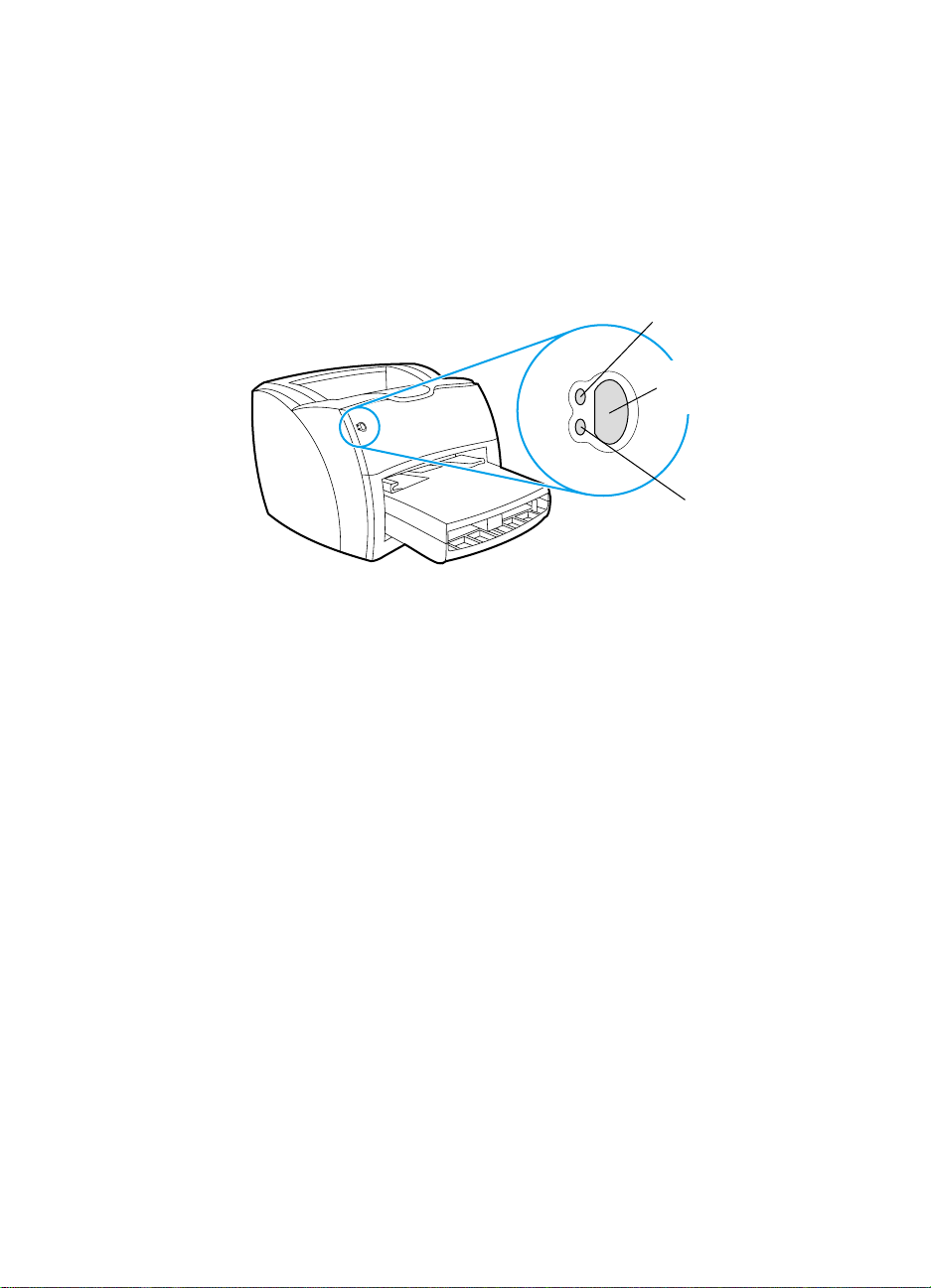
Printer control panel
The printer control panel has two lights and one lighted button. These
lights produce patterns that identify the printer status.
Figure 7. Printer control panel
l GO button and light—To print a self-test page or to continue
printing while in manual feed mode, press and release the G
button.
l Ready light—Indicates that the printer is ready to print.
l Attention light—Indicates that the main input tra y is empty, toner
cartridge door is open, toner cartridge is missing, or other errors.
Ready light (green)
Go button and light
Go button and light
(green)
(green)
Attention light (amber)
O
EN Identifying printer components 29
Page 30

Control panel light patterns
Light status legend
Symbol for “light off”
Symbol for “light on”
Symbol for “light blinking”
Figure 8. Light status legend
Table 9. Control panel light messages
Light status Condition of the printer Action
Ready
The printer is ready to print.
Processing
The printer is receiving or
processing data.
No action is necessary. To print a self-test
page, press and release the
the printer control panel.
Wait for the job to print.
GO button on
30 Chapter 2 - Installation and operation EN
Page 31

Table 9. Control panel light messages (continued)
Light status Condition of the printer Action
Manual feed or out of memory
The printer is in manual feed
mode or out of memory. You
can continue printing.
Door open, media out, no toner
cartridge, or paper jam
The printer is in an error state
that requires operator
intervention or help.
Make sure that you have loaded the correct
media. To continue printing, press and
release the
GO button.
The software controls manual feed. If you do
not want the printer to be in manual feed
mode, change the setting from the printer
properties. See the printer software for more
information.
The page being printed might be too complex
for the printer memory capacity.
l To continue printing, press and release
GO button.
the
l Reduce the resolution. See the user
guide for more information.
l Add more memory. See the user guide
for more information.
l Make sure that the toner cartridge door
is completely closed.
l Make sure that the media is loaded
correctly. See the user guide for
instructions.
l Make sure that the toner cartridge is
correctly installed in the printer. See the
user guide for instructions.
l If the printer still has an error, there is a
paper jam. See the user guide for
instructions.
Printer initialization/Cancel Job/
No action is necessary.
Cleaning Mode
A printer initialization is taking
place. If all lights blink for half of
a second or longer in a
sequence:
l the printer is initializing
l all previously sent print jobs
are being purged
l a cleaning page is being
printed
EN Identifying printer components 31
Page 32

Table 9. Control panel light messages (continued)
Light status Condition of the printer Action
Fatal error
All lights are on.
Accessory error
All lights are blinking.
l Turn the printer off and then back on.
l Unplug the printer for 5 minutes, and
then plug it back in.
l If the printer still has an error, see
chapter 6, “Troubleshooting.”
l Remove the DIMMs and reseat. See the
user guide for instructions.
l If the printer still has an error, replace the
DIMMs.
32 Chapter 2 - Installation and operation EN
Page 33

Copier/scanner control panel
The control panel on the optional copier/scanner has two buttons,
C
OPY and SCAN.
Figure 9. Copier/scanner control panel
l Copy—To perform Quick Copies, even if your computer is
powered off, press C
l Scan—To launch HP LaserJet Director, press SCAN. If
HP LaserJet Director is configured correctly, you can perform the
following tasks:
• Scan to Email
• Store documents electronically
• Edit text with Optical Character Recognition (OCR)
• Make multiple, customized, and color copies
OPY.
COPY button and
light (clear)
CAN button and
S
light (clear)
Note To cancel a scan or copy job from the control panel, simultaneously
press both buttons.
EN Identifying printer components 33
Page 34

Selecting media
Selecting media to print
You can use paper with up to 100% recycled fiber content if it meets
specifications. To order HP paper or the Print Media Guide for the
HP LaserJet printer family, see the user guide.
Highly textured stock might not print evenly. Very glossy paper might
jam or repel toner. Multipart forms can wrinkle or get jammed in the
printer. And paper in poor condition, such as paper with tears,
wrinkles, or bent edges, can jam.
Avoid envelopes that have a very slick finish, ones that have self-stick
adhesives, or those with clasps or windows. Also avoid envelopes
with thick, irregular, or curled edges, or areas that are wrinkled, torn,
or otherwise damaged.
Use a sturdy envelope of approximately 60 to 90 g/ m
weight. Use tightly constructed envelopes, and make sure that the
folds are sharply creased.
The main input tray can hold up to 250 sheets of 75 g/m
media. The priority input tray can hold up t o 10 sheets, one e nvelope,
or one piece of heavy media. Both can be adjusted to hold media
measuring from 76.2 by 127 mm (3 by 5 inches) to 216 by 356 mm
(8.5 by 14 inches). This includes, but is not limited to, the following
paper and envelope sizes:
2
(16 to 24 lb)
2
(20 lb) print
Table 10. Media types
Paper type Metric English
Letter 216 by 279 mm 8.5 by 11 in
Legal 216 by 356 mm 8.5 by 14 inches
Executive 184 by 267 mm 7.25 by 10.5 inches
A4 210 by 297 mm 8.25 by 11.75 inches
COM10 Envelopes 105 by 241 mm 4.13 by 9.5 inches
DL Envelopes 110 by 220 mm 4.33 by 8.67 inches
C5 Envelopes 162 by 229 mm 6.4 by 9 inches
B5 Envelopes 176 by 250 mm 6.9 by 9.85 inches
Monarch Envelopes 98.5 by 191 mm 3.88 by 7.5 inches
Custom size media custom custom
34 Chapter 2 - Installation and operation EN
Page 35

Selecting media to copy or scan
The copier/scanner for the printer can handle a broader range of
media sizes and types than the printer itself can. The follo wing are the
supported media sizes:
l Minimum: 45 by 89 mm (1.7 by 3.5 inches)
l Maximum: 216 by 356 mm (8.5 by 14 inches)
In addition, you can scan and cop y man y different types of media that
are typically not used for printing, such as newsprint, photographs,
business receipts, and business cards.
Note You must use a carrier sheet to feed small or delicate originals, such
as newsprint, through the copier/scanner without causing a jam. To
make a carrier sheet, use a piece of paper and a transpa re nc y, tape
the leading edges together , and load y our original between the sh eets.
Note You must feed business cards and any media that is smaller than
76.2 by 127 mm (3 by 5 inches) through the straight-through output
path. Y ou can also tape them to the leading edge of a carrier sheet and
feed them to the straight-through output bin.
Perform the following actions to minimize the possibility of jams:
l Remove self-stick notes.
l Remove staples and paper clips.
l Straighten any curls or wrinkles in documents before put ting them
into the document feeder tray.
l Do not insert any document with glue, correction fluid, or wet ink
on it.
l Do not insert gum-backed paper or labels.
l Place documents with tears, perforations, or punch ho les in a
carrier sheet, which you can buy or make. (See the user guide.)
l Avoid multiple-copy forms.
l Do not scan originals that are larger or smaller than supported
size limitations. See the user guide for more information.
Note T o obtain good results , it is important that you use the correct resolution
and color settings for your job . See the user guide for more information.
EN Selecting media 35
Page 36

Loading media
Loading media to print
Main input tray
The main input tray holds up to 250 sheets of 75 g/m2 (20 lb) paper or
a 25 mm (0.98 inches) stack of heavier media. Load media with the
top forward and the side to be printed facing up. To prevent jams and
skew, always adjust the side media guides.
Priority input tray
The priority input tray holds u p to 10 pages of 75 g/m2 (20 lb) paper or
one envelop e, tr ansparency, or card. Load media with the top f orw ard
and the side to be printed facing up. To prevent jams and skew,
always adjust the side medi a guides.
CAUTION If you try to print on media that is wrinkled, folded, or damaged in any
way, a jam might occur. See the user guide for more information.
Note When you add new media, mak e sure that you remo ve all of the media
from the input tray and straighten the stack of new media. This helps
preve nt multiple sheets of media from feeding through the printer at
one time, reducing paper jams.
Specific types of media
l Transparencies and labels: Load transparencies and labels
with the top forward and the side to be printed facing up. See the
user guide for more information.
l Envelopes: Load envelopes with the narrow, stamp side forward
and the side to be printed facing up. See the user guide for more
information.
l Letterhead or preprinted forms: Load with the top forward and
the side to be printed facing up. See the user guide for more
information.
l Cards and custom-sized media: Load with the narrow side
forward and the side to be printed facing up. See the user guide
for more information.
36 Chapter 2 - Installation and operation EN
Page 37

Loading media to copy or scan
To load originals in the optional copier/scanner:
1 Load the original with the side to be scanned facing up.
If you scan a business card:
a Loa d it wit h th e lon g sid e (callo ut 1) facing forward and the
text facing up.
b Use the straight-through output path. See the user guide for
more information.
2 Adjust the media guides.
3 Press S
Note When you add new originals , always remove the originals from the input
tray and straighten the stack.
CAUTION Small originals will cause a jam if they are not loaded correctly.
Figure 10. Scanning a business card
Note If you are editing text (OCR), ma ke sure that the top edge of the original
is the leading edge, and make sure that t he text is facing up. For more
information, see the user guide.
CAN to scan or press COPY for a copy.
2
1
EN Loading media 37
Page 38

Printer output paths
Output bin
The output bin is located on the top of the printer. Printed media is
collected here in the correct sequence when the straight-through
output door is closed. Use the output bin when printing nor mal and
large, collated documents.
Figure 11. Output bin
Straight-through output path
The straight-through output path is useful when you are printing
envelopes, transparencies, heavy media, or any media that tends to
curl when printed. Printed media exits in reverse order when the
straight-through output door is open .
Pull out for
long media.
Figure 12. Straight-through output door
Note Printed media does not stack wh en you use the straight-t hrough output
path. The media drops to the surface below unless you remove each
sheet as it exits the printer.
38 Chapter 2 - Installation and operation EN
Page 39

3Maintenance
Chapter contents
Life expectancies of consumables . . . . . . . . . . . . . . . . . . . . .40
User-replaceable parts. . . . . . . . . . . . . . . . . . . . . . . . . . . . . . 40
Replacing the printer pickup roller . . . . . . . . . . . . . . . . 41
Replacing the printer separation pad . . . . . . . . . . . . . .43
Replacing the copier/scanner separation pad . . . . . . . 45
Cleaning the equipment . . . . . . . . . . . . . . . . . . . . . . . . . . . . .46
Cleaning the print path . . . . . . . . . . . . . . . . . . . . . . . . .47
Cleaning the toner cartridge area. . . . . . . . . . . . . . . . . 48
Cleaning the printer pickup roller . . . . . . . . . . . . . . . . . 49
Cleaning the printer separation pad . . . . . . . . . . . . . . .50
Copier/scanner recalibration. . . . . . . . . . . . . . . . . . . . .51
Cleaning the scanner path . . . . . . . . . . . . . . . . . . . . . .51
EN Chapter contents 39
Page 40

Life expectancies of consumables
Inspect consumables when servicing the printer. Replace
consumables as needed, based on failure or wear, rather than on
usage.
The following table lists approximate schedules for replacing
consumables.
Table 11. Life expectancies of consumables
Estimated
Description Part number
Toner cartridge (user
replaceable)
Printer transfer roller RG9-1483-000CN 25,000 Can affect print quality and/or
Printer pickup roller RFO-1008-000CN 25,000 Look for glazing and/or cracks.
Printer separation pad RFO-1014-000CN 25,000 Can affect paper movement.
Printer subpads RAO-1065-000CN 25,000 Can affect paper movement.
Fuser assembly
(100-127 V)
Fuser assembly
(220-240 V)
Copier/scanner separation
pad kit
Copier/scanner R37-5020-000CN 10,000 Can affect document movement.
* The estimated toner cartridge life is based on letter- or A4-sized paper with an average of 5% toner
coverage and a medium density setting. Toner cartridge life can be extended further by conserving toner
using draft mode settings.
C7115A 2,500 When print becomes faint,
C7115X 3,500
RG9-1493-000CN 25,000 Can affect print quality and paper
RG9-1494-000CN 25,000 Can affect print quality and paper
RY7-5055-000CN 10,000 Can affect document movement.
life (pages) Remarks
redistribute toner in the cartridge
by gently shaking the cartridge
from side to side.
paper movement.
movement.
movement.
User-replaceable parts
Replace the copier/scanner separation pad, the printer pickup roller,
and the printer separation pad when the parts are near the end of
their life expectancies or if media frequently misfeeds.
40 Chapter 3 - Maintenance EN
Page 41

Replacing the printer pickup roller
1
2
3
If the printer regularly misfeeds (no
media feeds through), you might have to
replace or clean the pickup roller.
CAUTION
Failure to complete this procedure might
damage the printer.
1 Unplug the power cord from the
printer, and allow the printer to cool.
2 Open the toner cartridge door, and
remove the toner cartridge.
3 Locate the pickup roller.
4 Release the small, white tabs on
each side of the pickup roller by
pushing them away from the roller,
and then rotate the pickup roller
toward the front.
5 Gently pull the pickup roller up and
out.
4
5
EN User-replaceable parts 41
Page 42

6
6 Position the new pickup roller in the
slot of the previous pickup roller.
Note
Circular and rectangular pegs on each
side prevent you from incorrectly
positioning the pickup roller.
7
7 Rotate the top of the new pickup
roller into position until the white
tabs on each side of the roller snap
the roller into place.
8 Reinstall the toner cartridge, and
close the toner cartridge door.
9 Plug the printer in to turn it back on.
8
9
42 Chapter 3 - Maintenance EN
Page 43

Replacing the printer separation pad
1
2
3
4
Note
Before you change the separation pad,
clean the pickup roller. See “Cleaning
the printer pickup roller” on page 49 for
instructions.
If the input tray feeds more than one
page at a time, you might have to
replace the printer separation pad.
Recurring feed problems indicate that
the printer separation pad is worn.
1 Unplug the power cord from the
printer, and allow the printer to cool.
2 Remove the input trays.
3 Locate the blue separation pad.
4 To pry the separation pad up from
the spring-loaded base, insert a flatedged screwdriver in the slot under
the separation pad and twist until the
tabs are free.
5 Reach in throug h th e inp ut tray
opening, push the spring-loaded
base down with one hand, and pull
the separation pad up with the other
hand.
5
EN User-replaceable parts 43
Page 44

6
7
8
6 With one hand, re ac h th ro ug h th e
input tray opening, and push the
spring-loaded base down. With the
other hand, position the new
separation pad in the slot of the
previous separation pad.
Note
The tab on the right is larger to help you
position the separation pad correctly.
7 Snap both sides of the separation
pad firmly into place.
CAUTION
Make sure that the separation pad is
straight and that there is no space
between the separation pad and the
spring-loaded base. If the separation
pad is not straight or you see space on
one side, remove the separation pad,
make sure that the larger tab is on the
right, reinsert the separation pad, and
snap both sides into place.
8 Reinstall the input trays, and then
plug the printer in to turn it back on.
44 Chapter 3 - Maintenance EN
Page 45

Replacing the copier/scanner separation pad
1
2
2
3
If the optional copier/scanner feeds mor e
than one page at a time , you might have
to replace the copier/scanner separation
pad. Recurring feed problems indicate
that the pad is worn.
1 Press the copier/scanner door
release button and open the copier/
scanner door.
2 Locate the copier/scanner
separation pad and lift it straight up.
3 Press the new pad into place.
4 Close the copier/scanner door.
4
EN User-replaceable parts 45
Page 46

Cleaning the equipment
WARNING! Before you perform these steps, unplug the printer to avoid shock
hazard.
To maintain quality, thoroughly clean the printer:
l Any time a new toner cartridge is installed.
l After printing approximately 2,500 pag es.
l Whenever print quality problems appear.
Clean the outside of the printer with a water-dampened cloth. Clean
the inside with only a dry, lint-free cloth (such as a lens tissue).
To avoid permanent damage to the toner cartridge, do not use
ammonia-based cleaners on or around the printer.
WARNING! Avoid tou ching the heating element in the fuser. It might be very hot
and can cause burns.
CAUTION Do not touch the surface of the black sponge transfer roller.
Contaminants on the roller can cause print quality problems.
46 Chapter 3 - Maintenance EN
Page 47

Cleaning the print path
Use this process if you discover toner specks or dots on printouts.
This process produces a transparency with toner debris, which
should be discarded.
Note This process requires a transparency to remove dust and toner from
the print paper path. Do not use bond or rough paper.
Make sure the transparency you use meets media requirements for the
printer.
If transparency film is una v ailab le, you can use paper. If you must use
paper , perform the procedure two or three times to ensure proper
cleaning.
1 Load a transparency in the priority input tray.
2 Make sure that the printer is in the Ready state.
3 Press and hold the G
feeds through the printer slowly. Discard the transparency.
Note After you press and hold th e GO button, the three printer lights blink
until the cleaning process is complete.
O button for 10 seconds. The transparency
EN Cleaning the equipment 47
Page 48

Cleaning the toner cartridge area
1
2
3
Cleaning the toner cartridge area can
improve the quality of your printed
sheets.
WARNING!
Before cleaning the printer, disconnect it
from the power source and wait for the
printer to cool.
1 Open the toner cartridge door, and
remove the toner cartridge.
CAUTION
To prevent damage, do not expose the
toner cartridge to light. Cover the toner
cartridge if necessary. Also, do not touch
the black sponge transfer roller inside
the printer. Touching it can reduce the
print quality of output.
2 Wipe the media path area and the
toner cartridge cavity with a dry, lintfree cloth.
4
48 Chapter 3 - Maintenance EN
Note
Use only a dry, lint-free cloth to remove
dust and toner. Using a vacuum or other
device to clean inside the product can
damage it.
3 Replace the toner cartridge, and
close the toner cartridge door.
4 Plug the power cord back into the
printer.
Page 49

Cleaning the printer pickup roller
1
2
3
If you want to clean the pickup roller
rather than replace it, follow the
instructions below:
Remove the pic kup roller as de scribed in
steps 1 through 5 of “Replacing the
printer pickup roller” on page 41.
1 Dampen a lint-free cloth in isopropyl
alcohol, and scrub the roller.
WARNING!
Alcohol is flammable. Keep the alcohol
and cloth away from an open flame.
Before you close the printer and plug in
the power cord, allow the alcohol to dry
completely.
2 Using a dry, lint-free cloth, wipe the
pickup roller to remove loosened
dirt.
3 Allow the pickup roller to dry
completely before you reinstall it in
the printer. To reinstall the pickup
roller, see steps 6 through 9 of
"Replacing the printer pickup roller"
on page 42.
EN Cleaning the equipment 49
Page 50

Cleaning the printer separation pad
1
4
1
2
3
11
If you want to clean the sep aration pad
rather than replacing it, follow the
instructions below:
1 Remove the separat ion pad as
described in steps 1 through 5 of
“Replacing the printer separation
pad” on page 43.
2 Dab a lint-free cloth in isopropyl
alcohol, and scrub the pad.
WARNING!
Alcohol is flammable. Keep the alcohol
and cloth away from an open flame.
Before you close the printer and plug in
the power cord, allow the alcohol to dry
completely.
3 Using a dry, lint-free cloth, wipe the
pad to remove loosened dirt.
4 Allow the pad to dry completely
before you reinstall it in the printer.
To reinstall the pad, see steps 6
through 8 of “Replacing the printer
separation pad” on page 43.
50 Chapter 3 - Maintenance EN
Page 51

Copier/scanner recalibration
The optional copier/scanner automatically calibrates to the white
sheet opposite the image sensor at the beginning of each scan or
copy job.
Keep the white sheet clean to make sure the optional copier/scanner
calibrates correctly. See “Cleaning the scanner path” on page 51 for
information about cleaning the white sheet.
Cleaning the scanner path
1
2
3
You might have to clean the copier/
scanner if you can smudge the ink on
documents you scan, if the documents
have excessive amounts of dust or dirt
on them, or if there are smudges or other
marks on documents or scans of
documents.
Note
Be careful not to touch the glass surface
of the image sensor. If you inadvertently
touch the glass, clean it according to th e
instructions below.
1 Unplug the printer to turn the power
off, and wait for the scanner to cool.
2 Open the scanner door.
3 Dampen a clean cotton cloth with
isopropyl alcohol (pH7 or
neutral pH). With the damp cloth,
gently rub back and forth on the
white sheet. Also, use the damp
cloth to gently rub the rollers.
WARNING!
Alcohol is flammable. Keep the alcohol
and cloth away from an open flame.
Allow the alcohol to dry completely
before you plug in the power cord.
EN Cleaning the equipment 51
Page 52

4
4 Spray glass cleaner on another
piece of clean cotton cloth, and
carefully clean the glass on the
image sensor.
WARNING!
Make sure that the scanner is completely
dry before you plug in the printer power
5
cord.
5 Plug the printer in to turn it back on.
52 Chapter 3 - Maintenance EN
Page 53

4Operational overview
Chapter contents
Basic functions. . . . . . . . . . . . . . . . . . . . . . . . . . . . . . . . . . . .54
Formatter system . . . . . . . . . . . . . . . . . . . . . . . . . . . . . . . . . .55
Control panel . . . . . . . . . . . . . . . . . . . . . . . . . . . . . . . . 56
Draft mode . . . . . . . . . . . . . . . . . . . . . . . . . . . . . . . . . .56
MEt. . . . . . . . . . . . . . . . . . . . . . . . . . . . . . . . . . . . . . . . 56
Enhanced I/O . . . . . . . . . . . . . . . . . . . . . . . . . . . . . . . .56
PJL overview . . . . . . . . . . . . . . . . . . . . . . . . . . . . . . . .57
Printer functions . . . . . . . . . . . . . . . . . . . . . . . . . . . . . . . . . . .58
Engine control unit/power system. . . . . . . . . . . . . . . . .59
Image formation system . . . . . . . . . . . . . . . . . . . . . . . .64
Printer paper-feed system . . . . . . . . . . . . . . . . . . . . . .67
Jam detection . . . . . . . . . . . . . . . . . . . . . . . . . . . . . . . . 69
Optional copier/scanner . . . . . . . . . . . . . . . . . . . . . . . . . . . . .71
Optical system . . . . . . . . . . . . . . . . . . . . . . . . . . . . . . . 71
Document pickup and feed systems. . . . . . . . . . . . . . .71
Basic sequence of operation (formatter-to-printer). . . . 73
EN Chapter contents 53
Page 54

Basic functions
This chapter presents a functional ove rvie w of th e pr int er’s
processes. The following systems are discussed:
l formatter
l printer functions
• engine control unit (ECU) system/power system
• image formation system
• paper-feed system (printer) and
l optical system (optional copier/scanner)
The printer has an optional copier/scanner. Operat ion sequences of
the printer are controlled by the ECU. Operation se qu en ce s of the
optional copier/scanner are controlled by the formatter.
Figure 13. Basic configuration
54 Chapter 4 - Operational overview EN
Page 55

Formatter system
The formatter is responsible for the following:
l controlling the optional copier/scanner
l formatting and controlling copies
l receiving and processing print data from the printer interface
l monitoring the control panel and relaying printer status
information
l developing and coordinating data placement and ti ming with the
print engine
l communicating with the host computer through the bidirectional
interface
The formatter receives print data from the bidirectional Extended
Capabilities Port (ECP) mode interface or Universal Serial Bus (USB)
interface and converts it into a dot image . The ECU synch ronizes t he
image formation system with the paper-feed system and signals the
formatter to send the print image data. The formatter sends the print
image data (dots) in the form of a video signal, and the printing
process begins.
Central processing unit
The formatter incorporates an embed ded Coldfire V3 microprocessor
operating at 90 MHz.
RAM
l One bank of Non-Volatile RAM (NVRAM) stores parameters.
l Dynamic random access memory (DRAM) provides temporary
storage of copy, scan, and print data.
Parallel interface or Universal Serial Bus interface
The formatter receives incoming data through it s bidirectional ECP or
USB interface. This interface provides high-speed, two-way
communication between the printer and the host, allowing you to
change printer settings and monitor printer status from the host
computer.
EN Formatter system 55
Page 56

Control panel
l three front panel status lights (one contained in the GO button)
l GO button
Draft mode
Depending on which printer driver is used, selecting draft or
EconoMode from the printer driver allows the printer to use
approximately 50% less toner, extending the life of the toner
cartridge.
MEt
The Hewlett-Packard Memory Enhancement technology (MEt )
effectively doubles the standard memory through a varie ty of font and
data-compression methods.
Enhanced I/O
The Enhanced I/O feature allows printer memory to be used for
storing data received from the host computer. When Enha nced I/ O is
enabled, you can send more data to the print e r in sh or ter amo unt s of
time, which allows you to return to your application sooner. Enhan ced
I/O has the following options:
l Auto—allows the printer to use Enhanced I/O memory allocation
to increase the speed of data transfer from the host computer to
the printer, if necessary.
l Off—uses the minimum amount of printer memory for storing
data sent from the host computer.
l Page Protect—allows the formatter to create the entire page
image in page buffer memory before physically moving the media
through the printer. This process ensures that the entire page will
be printed. The default setting is Auto.
Page complexity (ruling lines, complex graphics, or dense text)
can exceed the printer’s ability to create the page image fast
enough to keep pace with the image formation process. If Page
Protect is disabled and a page is too complex, the page might
56 Chapter 4 - Operational overview EN
Page 57

print in parts (for example, the top half on one page and the
bottom half on the next page). Some print-data loss is likely in
these instances, and the printer will display an error message.
PJL overview
Printer Job Language (PJL) is an integral part of configuration, in
addition to the standard Printer Command Language (PCL). With
standard ECP cabling, PJL allows the printer to perform functions
such as:
l Two-way communication with the host computer through a
bidirectional parallel or USB connection. The printer can tell the
host such things as the control panel status.
l Isolation of print envir onment settings from on e print job to the
next. For example, if a print job is sent to t he print er in lan dscape
mode, the subsequent print jobs print in landscape only if they
are formatted for landscape printing.
EN Formatter system 57
Page 58

Printer functions
Printer functions are divided into five groups:
l engine control
l formatter
l image formation
l laser/scanner
l pickup and feed
The following figure is a block diagram of the printer unit:
Figure 14. Printer unit functional block diagram
58 Chapter 4 - Operational overview EN
Page 59

Engine control unit/power system
The engine control unit (ECU) coordinates all print engine activities,
drives the laser, and coordinates print data from the for matter with the
image formation process. The ECU also includes power supply and
distribution circuitry.
Note In several other HP LaserJet products, the ECU is also known as the
controller PCA or the DC controller PCA.
The ECU controls the following systems and functions:
l Printer engine control
• paper motion monitoring and control (printing)
• motor
l Printer laser/scanner
l Power sy stem
• AC power distribution
• DC power distribution
• overcurrent/overvoltage protection
• high-voltage power distribution
EN Printer functions 59
Page 60

The following figure shows the various ECU loads:
Figure 15. ECU loads
60 Chapter 4 - Operational overview EN
Page 61

Printer engine control system
Paper motion monitoring and control
The ECU controls paper motion in the printer by continuously
monitoring the various paper sensors and coordina ting the timing with
the other print processes.
For a detailed explanation of paper movement and the interaction of
the photosensors and solenoid with the paper movement pr ocess,
see “Printer paper-feed system” on page 67.
Motor
The motor is controlled by the ECU. The motor provides all of the
printer paper movement.
Printer laser/scanner drive
The ECU sends signals to the laser/scanner assembly to modulate
the laser diode “on” and “off” and to drive the laser/scanner motor.
Figure 16. Overview of laser/scanner operatio n
EN Printer functions 61
Page 62

Power system on ECU
The AC, DC, and high-voltage power su pply circuit s ar e all contai ned
within the ECU.
AC power distribution
The AC power circuitry supplies AC voltage whenever the power cord
is connected to the AC power source. AC voltage is distr ibut ed t o the
DC power supply circuitry and to the AC driver circuitry, which
controls AC voltage to the fuser assembly heating element.
DC power distribution
The DC power distribution circuitry, located on the ECU, distributes
+3.3 Vdc, +5 Vdc, and +24 Vdc as follows:
l +3.3 Vdc: Formatter
Laser/beam detect circuitry ECU
Photosensors
l +5 Vdc: Formatter
ECU
Laser/beam detect circuitry
l +24 Vdc: Motor
Exhaust fan
Laser/scanner motor
Document scanner motor
Solenoid
Formatter (routing only)
High voltage power supply
Fuser safety circuit
Overcurrent/overvoltage
There are two overvoltage devices in this printer:
l Fuse F101 provides overcurrent protection for the fusing system
circuitry. Checking or replacing the fuse requires the removal of
the ECU. Fuse F102 provides overcurrent protection to the
printer DC power supply circuitry.
l In addition, the +24 Vdc and +3.3 Vdc power circuitr y contains an
overcurrent protection circuit th at au tomatically shuts off the
output voltage when an overcurrent condition occurs as a result
of a short or an abnormal voltage on the load side.
62 Chapter 4 - Operational overview EN
Page 63

High-voltage power distribution
The high-voltage power supply applies an overlap of DC and AC
voltage to the primary charging roller and the developing roller. This
circuit also applies a positive or negative DC voltage to the transfer
roller according to the instructions from the engine control unit.
This circuit also controls the image density by changing the primary
AC voltage and the developing AC bias acco rding to t he pr int densit y
setting.
High voltage is disabled when the printer door is open.
Figure 17. High-voltage power supply circuit
EN Printer functions 63
Page 64

Image formation system
Laser printing requires the interaction of several different
technologies including electronics, optics, and electrophotographics
to provide a printed page. Each process functions inde pen dently an d
must be coordinated with the other printer processes. Image
formation consists of seven processes:
Figure 18. Image formation block diagram
Toner cartridge
As the focal point of the image formation system, the toner cartridge
houses the cleaning, conditioning, and developing stages of the
process. The toner cartridge contains the photosensitive primary
charging roller, developing station, toner cavity, and cleaning station.
By including these components (which wear, degrade, or are
consumed) in the replaceable toner cartridge, the need for many
service calls is eliminated. The special photos en sitive properties of
the drum form an image on the drum surface and then transfer the
image to media.
CAUTION The printer toner car tridge does not include a light-blocking shut ter. Do
not expose the drum to light, which can permanently da mage the drum.
Protect the toner cartridge whenever removing it from the printer.
64 Chapter 4 - Operational overview EN
Page 65

Breakdown of the seven image formation processes
1 Conditioning stage (primary charging)—This process applies
a uniform negative charge to the surface of the drum with the
primary charging roller, which is located in the toner cartridge.
The primary charging roller is coated with conductive rubber. An
AC bias is applied to the roller to erase any residual char ges from
any previous image. In addition, the primary charging roller
applies a negative DC bias to create a uniform negati ve pot en ti al
on the drum surface. The print density setting modifies the DC
voltage.
2 Writing stage (scanning exposure)—During this process, a
modulated laser diode projects the beam onto a rotat ing scanning
mirror. As the mirror rotates, the beam reflects off the mirror, first
through a set of focusing lenses, then off a mirror, and finally
through a slot in the top of the toner cartridge, and onto the
photosensitive drum. The beam sweeps the drum from lef t to
right, discharging the negative potential wherever the beam
strikes the surface. This creates a latent electrostatic image,
which later is developed into a visible image.
Because the beam sweeps the entire length of the drum while the
drum rotates, the entire surface area of the dr um can be covered.
At the end of each sweep, the beam strikes the beam dete ct lens,
generating the beam detect signal (BD signal). The BD signal is
sent to the ECU where it is converted to an electrical signal used
to synchronize the output of the next scan line of data.
3 Developing stage—During this process, the latent electrosta tic
image is present on the drum. The toner particles obtain a
negative surface charge by rubbing against the developing
cylinder, which is connected to a negative DC supply. The
negatively charged toner is attracted t o the d ischarged ( exposed,
grounded) areas of the drum, and it is repelled from the
negatively charged (unexposed) areas.
4 Transf e r stage—During this process, the toner image on the
drum surface is transferred to the media. The transfer roller
applies a positive charge to the back of the media, which attracts
the negatively charged toner on the drum surface to the media.
After separation, the drum is cleaned and con ditioned for the next
image.
EN Printer functions 65
Page 66

5 Separation stage—During this process, the media separates
from the drum. To stabilize the feed system and prevent toner
dropouts on the printed image at low temperature and humidity,
the static eliminator reduces the charge on the back of the media.
6 Fusing stage—During this process, the heat and pressure fuse
the toner into the media to produce a permanent image. The
media passes between a heated fusing element and a soft
pressure roller, which melt the toner and press it into the media.
7 Drum cleaning stage—During this process, the cleaning blade
is in contact with the surface of the drum at all times. As the drum
rotates during printing, it wipes excess toner off of the drum and
stores it in the waste toner receptacle.
66 Chapter 4 - Operational overview EN
Page 67

Printer paper-feed system
Step 1 The main input tray and the priority input tray merge into one,
main input area. Media placed in any of these areas enables
the paper-out sensor (PS201), which informs the ECU that
media is present. The following steps occur when the printer
receives a print job:
Step 2 The ECU enables the laser/scanner assembly and the motor.
Paper motion begins when the ECU energizes the solenoid
(SL001).
Step 3 The paper pickup roller rotates once. The paper lift plate
pushes the media against the pickup roller.
Step 4 The pickup roller grabs the top sheet and advances it to the
feed assembly drive rollers. To ensure that only one sheet is
fed, a main separation pad and two subpads hold the
remainder of the stack in place.
Step 5 The feed assembly drive rollers advance the media to the
paper top sensor (PS402). This sensor informs the ECU of
the exact location of the leading edge of media, so that the
image being written on the photosensitive drum can be
precisely positioned on the page.
Step 6 The feed assembly drive rollers then advance the media to
the transfer area where the toner image on the
photosensitive drum is transferred to media.
Step 7 After the image is transferred, the media enters the fuser
assembly where heat from the fuser and pressure from the
pressure roller permanently bond the toner image to media.
The paper delivery sensor (PS401) determines that media
has successfully moved out of the fusing area.
Step 8 The fuser assembly exit rollers deliver media to either the
paper output bin or the straight-through output path,
depending upon the position of the straight-through output
path door.
EN Printer functions 67
Page 68

Figure 19. Printer path
68 Chapter 4 - Operational overview EN
Page 69

Jam detection
The paper-out sensor (PS201) detects the presence of media in
either the priority input tray or the main input tray. The paper top
sensor (PS402) and the paper delivery sensor (PS401) detect media
moving through the printer. If a jam is detected, the ECU immediat ely
stops the printing process and displays a jam message on the control
panel.
A jam can be detected under any of the following conditions:
l Pickup delay jam—Media does not reach the paper top sensor
(PS402) after the pickup solenoid (SL 001) has been turned on
twice (the original pickup plus a retry) within 2.8 seconds.
l Pickup stationary jam—The paper top sensor (PS402) does not
detect the trailing edge of media within 4.6 seconds of detecting
the leading edge.
l Delivery-delay jam—The paper delivery sensor (PS401) does
not detect the leading edge of media within 2.1 seco nds aft er th e
paper top sensor (PS402) detects the leading edge.
l Wrapping jam—The paper delivery sensor (PS401) does not
detect the trailing edge of the media within 1.5 seconds after the
paper top sensor (PS402) detects the leading edge and withi n 10
seconds after the paper delivery sensor (PS401) detects the
leading edge.
l Delivery-stationary jam—The paper delivery sensor (PS401)
does not detect the leading edge of medi a within 2.2 seconds
after the paper top sensor (PS402) detects the trailing edge.
l Residual paper jam—The paper top sensor (PS402) or the
paper delivery sensor (PS401) detect media in the initial rotation
period.
EN Printer functions 69
Page 70

2
Solenoid, photosensors, and switches
The following figure shows the locations of the solenoid,
photosensors, and switches.
1
6
3
4
7
5
Figure 20. Solenoid, photosensors, and switches
1 Paper delivery sensor (PS401) senses when paper has
successfully moved out of the fusing area.
2 Power switch
Note Products sold in North America do not have power switches.
3 Paper top sensor (PS402) detects the leading and trailing edges
of the paper. It synchronizes the photos enstive drum and the top
of the paper.
4 Engine test switch (SW201); see “Engine test” on page 149 for an
explanation of the switch.
5 Door-open switch (SW301) detects whether or not the printer
door is closed and the toner cartridge is present. Printing cannot
continue until the printer door is closed and the toner cartridge is
in its correct position.
6 Solenoid (SL001) enables the pickup roller.
7 Paper-out sensor (PS201) senses when paper is in the main
input tray or the priority input tray.
70 Chapter 4 - Operational overview EN
Page 71

Optional copier/scanner
The optional copier/scanner consists of the optical system and the
document pickup and feed systems.
Optical system
The optical system, also known as the contact image sensor,
contains the following:
l light-emitting diode (LED) array
l contact glass
l rod lens array
l sensor array
The light source has three LEDs and is controlled by the formatter.
Light reflected from documents pa sses through the rod lens array and
focuses on the sensor array.
The sensor array consists of 5,160 photo transistors: 1 5 driver circuits
amplify the light reception output in units of 344 phototransisto rs. The
image data is converted and sent from the driv er circu i ts to th e
formatter.
Document pickup and feed systems
The document pickup and feed systems contain a pickup roller, feed
roller, and delivery roller, all of which are driven b y the copier/scanner
motor (M1).
The document top sensor (U20) detects th e top and bottom edges of
the document.
EN Optional copier/scanner 71
Page 72

Copier/scanner path
The following figure shows the copier/scanner path.
Figure 21. Copier/scanner path
72 Chapter 4 - Operational overview EN
Page 73

Basic sequence of operation (formatter-toprinter)
The operation sequence of the printer is controlled by the
microprocessor (CPU) on the ECU. The following events take place
during normal printer operation:
Table 12. Basic sequence of operation
Period Purpose Remarks
WAIT
After the printer is turned on
until the end of the initial
rotation of the main motor.
STBY (Standby)
From the end of the WAIT
period or the LSTR period
until the pickup command is
input from the formatter. Or,
from the end of the LSTR
period until the printer is
turned off.
INTR (Initial Rotation Period)
After the pickup command
has been input from the
formatter until the media
reaches the paper top sensor
(PS402).
PRINT (Print)
From the end of the initial
rotation until the primary
voltage goes OFF.
LSTR (Last Rotation Period)
After the primary voltage
goes OFF until the main
motor stops rotating.
To clear the drum surface of
potential and to clean the
primary charging roller.
To keep the printer ready to
print.
To stabilize the
photosensitive drum
sensitivity in preparation for
printing. Also to clean the
primary charging roller.
To form images on the
photosensitive drum based
on the VIDEO signals (/VDO,
VDO) input from the formatter
and to transfer the toner
image onto the media.
To deliver the last page. Also
to clean the primary charging
roller.
Detects whether or not the
cartridge is installed.
When the pickup command is
input from the video
controller, the printer enters
the INTR period immediately
after the end of the LSTR
period.
EN Optional copier/scanner 73
Page 74

Figure 22. General timing diagram
74 Chapter 4 - Operational overview EN
Page 75

Removal and
5
replacement
Chapter contents
Removal and replacement strategy . . . . . . . . . . . . . . . . . . . . 77
Required tools . . . . . . . . . . . . . . . . . . . . . . . . . . . . . . .77
Before performing service . . . . . . . . . . . . . . . . . . . . . .78
Toner cartridge . . . . . . . . . . . . . . . . . . . . . . . . . . . . . . . 78
Parts removal order . . . . . . . . . . . . . . . . . . . . . . . . . . . 79
Covers . . . . . . . . . . . . . . . . . . . . . . . . . . . . . . . . . . . . . . . . . . 80
Left side cover . . . . . . . . . . . . . . . . . . . . . . . . . . . . . . . 80
Optional copier/scanner . . . . . . . . . . . . . . . . . . . . . . . .81
Back cover . . . . . . . . . . . . . . . . . . . . . . . . . . . . . . . . . .82
Right side cover . . . . . . . . . . . . . . . . . . . . . . . . . . . . . . 84
Top cover . . . . . . . . . . . . . . . . . . . . . . . . . . . . . . . . . . .87
Control panel assembly . . . . . . . . . . . . . . . . . . . . . . . . 88
Front cover assembly . . . . . . . . . . . . . . . . . . . . . . . . . .89
Internal assemblies . . . . . . . . . . . . . . . . . . . . . . . . . . . . . . . .96
Transfer roller. . . . . . . . . . . . . . . . . . . . . . . . . . . . . . . .96
Formatter . . . . . . . . . . . . . . . . . . . . . . . . . . . . . . . . . . . 97
Laser/scanner assembly. . . . . . . . . . . . . . . . . . . . . . . .99
Fuser assembly . . . . . . . . . . . . . . . . . . . . . . . . . . . . .101
Output rollers . . . . . . . . . . . . . . . . . . . . . . . . . . . . . . . 105
Motor . . . . . . . . . . . . . . . . . . . . . . . . . . . . . . . . . . . . .107
Solenoid . . . . . . . . . . . . . . . . . . . . . . . . . . . . . . . . . . .108
Fan assembly. . . . . . . . . . . . . . . . . . . . . . . . . . . . . . .110
Right plate assembly . . . . . . . . . . . . . . . . . . . . . . . . .112
Pickup assembly. . . . . . . . . . . . . . . . . . . . . . . . . . . . .114
EN Chapter contents 75
Page 76

Pickup roller shaft . . . . . . . . . . . . . . . . . . . . . . . . . . . 117
Paper lift plate assembly . . . . . . . . . . . . . . . . . . . . . . 119
Left plate assembly . . . . . . . . . . . . . . . . . . . . . . . . . . 120
Bottom assemblies . . . . . . . . . . . . . . . . . . . . . . . . . . . . . . . 121
ECU pan . . . . . . . . . . . . . . . . . . . . . . . . . . . . . . . . . . 121
Paper-feed assembly. . . . . . . . . . . . . . . . . . . . . . . . . 125
76 Chapter 5 - Removal and replacement EN
Page 77

Removal and replacement strategy
This chapter documents the removal and replacement of field
replaceable units (FRUs) only.
Replacement is generally the reverse of removal. Occasionally, notes
are included to provide directions for difficult or critical replacement
procedures.
WARNING! Unplug the power cord from the power outlet before attempting
to service the HP LaserJet 1200 printer. If this warning is not followed,
severe injury can result. Certain functional checks during
troubleshooting must be performed with power supplied to the printer.
However, the power supply should be disconnected during removal.
Never operate or service the printer with the pro tective cover removed
from the laser/scanner assembly. The reflected b eam, although
invisible, can damage your eyes.
The sheet metal edges of the printer can be sharp. Use caution wh en
working on the printer.
CAUTION Some printer parts are electrostatic discharge (ESD) sensitive. Always
perform service work at an ESD-protected workstation.
To install a self-tapping screw, first turn it counterclockwise to align it
with the existing thread pattern, then carefully turn it clockwise to
tighten. Do not overtighten. If a self-tapping screw-hole becomes
stripped, repair the screw-hole or replace the affected assembly.
Always remove the toner cartridge before removing or r eplacing parts.
See “Toner cartridge” on page 78.
Required tools
l #2 Phillips-head screwdriver with magnetic tip
l Small flatblade screwdriver
l Needle nose pliers
l ESD mat
l Penlight
CAUTION A PoziDriv screwdriver will damage screw heads on the printer. Use a
#2 Phillips-head screwdriver.
EN Removal and replacement strategy 77
Page 78

Before performing service
l Remove all media from the printer.
l Unplug the power cable.
l Place the printer on an ESD mat.
l Remove the main input tray.
l If the optional copier/scanner is attached, remove the copier/
scanner media input tray and the copier/scanner output bin.
l Remove the toner cartridge (see page 78).
Toner cartridge
Note You will feel resistance when you open the toner cartridge door.
1 Open the toner cartridge door, which lifts the toner cartridge
toward you.
2 Remove the toner cartridge.
CAUTION To prevent damage, do not expose the toner cartridge to light. Cover
it with a piece of paper.
Figure 23. Removing the toner cartridge
78 Chapter 5 - Removal and replacement EN
Page 79

Pickup roller
Separation pad
Transfer roller
Left side cover
Optional copier/scanner
Back cover
Formatter ECU Solenoid
Parts removal order
Use the following diagram to determine which parts must be remove d
before removing other parts:
Right side cover
Top cover
Fan assembly
Control panel
Front cover assembly
Right plate assembly
Pickup assembly
Pickup roller shaft
Paper lift plate
(ECU)
Paper-feed assembly
(Formatter)
Left plate assembly
Laser/scanner
Fuser assembly
Output rollers
assembly
Motor
Note The ECU and the formatter are listed twice.
The ECU must be removed to gain access to the paper-feed assembly.
To remove the ECU only, remove the right side cover.
The formatter must be removed to gain access to the left plate assembly.
To remove the formatter only, remove the left side cover.
EN Removal and replacement strategy 79
Page 80

Covers
Left side cover
1 Open the toner cartridge door.
2 Pull out on the notch (callout 1) on the back of the cover.
3 Rotate the cover away from the printer.
2
1
Figure 24. Removing the left side cover
80 Chapter 5 - Removal and replacement EN
Page 81

Optional copier/scanner
CAUTION You must unplug the printer before removing or reinstalling the optional
copier/scanner, or you might damage bo th the printer and the optional
copier/scanner.
1 Remove the left side cover (see page 80).
2 Pull up on the flat flexible cable to disconnect it from the
connector (callout 1) on the formatter.
Note The optional copier/scanner has two tabs that hook into the underside
of the printer output bin. Another tab and a pin stabilize the optional
copier/scanner in the back. Use care so that you do not bend or break
the three tabs or the pin.
3 Lift the rear of the optional copier/scanner up (callout 2) and pull it
forward (callout 3) to remove it.
2
3
2
2
2
1
Figure 25. Removing the optional copier/sca n ne r
EN Covers 81
Page 82

Back cover
1 Remove the left side cover (see page 80).
2 Open the straight-through output door.
3 Remove two screws (callout 1) from the back of the printer.
2
1
Figure 26. Removing the back cover (1 of 2)
82 Chapter 5 - Removal and replacement EN
Page 83

4 Press down and hold the two release levers (callout 1) and pull
the back cover off of the printer.
2
1
Figure 27. Removing the back cover (2 of 2)
EN Covers 83
Page 84

Right side cover
1 Open the toner cartridge door.
2 Remove the back cover (see page 82).
3 Remove one screw (callout 1) on the back of the printer.
2
1
Figure 28. Removing the right side cover (1 of 3)
84 Chapter 5 - Removal and replacement EN
Page 85

4 Lift the right side of the printer and release the tab (callout 1) on
the bottom of the cover.
2
1
Figure 29. Removing the right side cover (2 of 3)
EN Covers 85
Page 86

5 While continuing to press the release tab, grasp the top of the
cover and rotate it away from the printer.
Figure 30. Removing the right side cover (3 of 3)
86 Chapter 5 - Removal and replacement EN
Page 87

Top cover
1 If the printer has the optional copier/scanner attached, remove it
(see page 81).
2 Remove the left side, back, and right side covers (see pages 80
through 86) and open the toner cartridge door.
3 Loosen two screws (callout 1) on the back of the printer.
4 Remove two screws (callout 2) on the top of the printer.
5 Lift the cover off of the printer.
2
2
2
1
Figure 31. Removing the top cover
EN Covers 87
Page 88

Control panel assembly
1 Remove the left side, back, right side, and top covers (see pages
80 through 87).
2 Disconnect the control panel cable (callout 1) from the formatter.
3 Remove two screws (callout 2 and callout 3) from the top of the
control panel assembly.
Note The first screw (callout 2) secures the control panel casing, and the
second screw (callout 3) secures the inte rnal bracke t. Be su re to h old
the assembly together as you remove it.
Rotate the control panel assembly toward the fro n t of the printe r to
release the tab (callout 4).
4 Remove the control panel assembly.
2
2
2
3
2
1
2
4
Figure 32. Removing the control panel
88 Chapter 5 - Removal and replacement EN
Page 89

Front cover assembly
The front cover assembly is composed of three pieces:
l front cover (the frame that surrounds the main input tray)
l toner cartridge door
l front guide assembly (the internal shelf that attaches the front
cover and the toner cartridge door to the printer)
Front cover
1 Remove the left side, right side, and top covers (see pages 80
through 87).
2 Close the toner cartridge door.
3 Loosen two screws (one shown, callout 1), one on each side of
the cover.
2
1
Figure 33. Removing the front cover (1 of 2)
EN Covers 89
Page 90

4 Pull the top of the front cover away from the printer to release the
three tabs (callout 1).
5 Lift the front of the printer to release the tab s on th e bottom of the
front cover.
6 Remove the front cover.
2
1
Figure 34. Removing the front cover (2 of 2)
90 Chapter 5 - Removal and replacement EN
Page 91

Toner cartridge door
1 Remove the left side, back, right side, and top covers (see pages
80 through 87).
1 Remove the control panel assembly (see page 88).
2 Remove the front cover (see page 89).
3 Open the toner cartridge door.
4 Remove one screw (callout 1) from the bracket on the right side
of the printer, and remove the bracket.
5 At the right side, press the two small tabs (callout 2) on the inside
of the toner cartridge door arm to release it.
6 Repeat on the left side.
2
1
2
2
Figure 35. Removing the toner cartridge door (1 of 2)
EN Covers 91
Page 92

7 Unhook the toner cartridge door hinge on the right side, and slide
the toner cartridge door toward the left to remove it.
2
1
Figure 36. Removing the toner cartridge door (2 of 2)
To reinstall
Lift the toner cartridge door hinge above the stop (callout 1).
Otherwise, the toner cartridge door will not close.
92 Chapter 5 - Removal and replacement EN
Page 93

Front guide assembly
1 From the front of the printer, remove two screws (callout 1).
2
1
Figure 37. Removing the front guide assembly (1 of 3)
EN Covers 93
Page 94

2 On the right side, release the lower tab (callout 1) and the upper
tab (callout 2).
2
1
2
2
Figure 38. Removing the front guide assembly (2 of 3)
94 Chapter 5 - Removal and replacement EN
Page 95

3 On the left side, release the upper tab (callout 1) and the lower
tab (callout 2).
4 Remove the front guide assembly.
2
1
2
2
Figure 39. Removing the front guide assembly (3 of 3)
EN Covers 95
Page 96

Internal assemblies
Transfer roller
1 Open the toner cartridge door and remove the toner cartridge
(see page 78).
2 Use needle nose pliers to gently squeeze the two small tabs on
the transfer roller.
3 Lift the transfer roller up, slide it to the right, and lift it out of the
printer.
Figure 40. Removing the transfer roller
Note Do not misplace the small grounding spring that is underneath t he right
side of the transfer roller.
CAUTION Do not touch the black sponge portion of the transfer roller.
96 Chapter 5 - Removal and replacement EN
Page 97

Formatter
1 Remove the left side cover (see page 80).
2 If the optional copier/scanner assembly is attached to the printer,
disconnect the copier/scanner cable (callout 1) from the
formatter.
3 Disconnect the two flat flexible cables (callout 2) from the zero
insertion force (ZIF) connectors on the formatter.
4 Unplug the laser/scanner cable (callout 3) and the control panel
cable (callout 4) from the formatter.
2
1
2
3
2
4
2
2
Figure 41. Removing the formatter (1 of 2)
EN Internal assemblies 97
Page 98

5 Remove five screws (callout 1).
6 Rotate the formatter up and off of the hooks on the chassis and
remove it from the printer.
7 Disconnect and remove the formatter shield.
2
1
Figure 42. Removing the formatter (2 of 2)
To reinstall
When you reconnect the cable, make sure you lock the ZIF
connectors back into place.
98 Chapter 5 - Removal and replacement EN
Page 99

Laser/scanner assembly
1 Remove the left side, back, right side, and top covers (see pages
80 through 87).
2 Disconnect the flat flexible cable from its socket (callout 1) on the
laser/scanner.
3 Disconnect the cable connector (callout 2) from the formatter.
2
1
2
2
Figure 43. Removing the laser/scanner (1 of 2)
EN Internal assemblies 99
Page 100

4 Release the two tab s (ca llo ut 1), on e on ea ch sid e of the sh ut ter
lever, and lift the shutter lever straight up to remove it.
Note Make sure you do not misplace the small spring that is under the shutter
lever.
5 Remove four screws (callout 2) and then lift the assembly off of
the printer.
6
2
2
2
1
Figure 44. Removing the laser/scanner (2 of 2)
To reinstall
Insert the spring into the hole on the laser/scanner before you snap
the shutter lever back into place.
100 Chapter 5 - Removal and replacement EN
 Loading...