

Page 1

User’s Guide
/LQH-HW™
Printers
Page 2

Page 3

LineJet™ Printers
User’s Guide
Page 4

READ THIS SOF TWARE LICENSE AGREEMENT BEFORE
USING THIS PRINTE R
Software License Agreement
CAREFULLY READ THE FOLLOWING TERMS AND CONDITIONS
BEFORE USING THIS PRINTER. USING THIS PRINTER INDICATES
YOUR ACCEPTANCE OF THESE TERMS AND CONDITIONS. IF YOU DO
NOT AGREE TO THESE TERMS AND CONDITIONS, PROMPTLY RETURN
THE PRINTER AND ALL ACCOMPANYING HARDWARE AND WRI TTEN
MATERIALS TO THE PLACE YOU OBTAINED THEM, AND YOUR MONEY
WILL BE REFUNDED.
Definitions.
“Software” shall mean the digitally encoded, machine-readable data and
program. The term “Software Product” includes the Software resident in the
printer and its documentation. The Software Product is licensed (not sold) to
you, and Hewlett-Packard either owns or licenses from other vendors who
own, all copyright, trade secret, patent and other proprietary rights in the
Software Product.
License.
1. Authorized Use. You agree to accept a non-exclusive license to use the
Software resident in the printer solely for your own customary business or
personal purposes.
2. Restrictions.
a. To protect the proprietary rights of Hewlett-Packard, you agree to
maintain the Software Product and other proprietary information
concerning the typefaces in strict confidence.
b. You agree not to duplicate or copy the Software Product.
c. You shall not sublicense, sell, lease, or otherwise transfer all or any
portion of the Software Product separate from the printer, without the
prior written consent of Hewlett-Packard.
d. You may not modify or prepare derivative works of the Software
Product.
e. You may not transmit the Software Product over a network, by
telephone, or electronically using any means; or reverse engineer,
decompile or disassemble the Software.
f. You agree to keep confidential and use your best efforts to prevent
and protect the contents of the Software Product from unauthorized
disclosure or use.
3. Transfer. You may transfer the Software Product with the printer, but only
if the recipient agrees to accept the terms and conditions of this
Agreement. Your license is automatically terminated if you transfer the
Software Product and printer.
Page 5

Limited Software Product Warranty
Hewlett-Packard warrants that for ninety (90) days after delivery, the Software
will perform in accordance with specifications published by Hewlett-Packard.
Hewlett-Packard does not warrant that the Software is free from all bugs,
errors and omissions.
Remedy
Your exclusive remedy and the sole liability of Hewlett-Packard in connection
with the Software is replacement of defective software with a copy of the
same version and revision level.
Disclaimer of Warranties and Limitation of Remedies
1. THE PARTIES AGREE THAT ALL OTHER WARRANTIES, EXPRESS
OR IMPLIED, INCLUDING WARRANTIES OF FITNESS FOR A
PARTICULAR PURPOSE AND MERCHANTABILITY ARE EXCLUDED.
Hewlett-Packard does not warrant that the functions contained in the
Software will meet your requirements or that the operation of the Software
will be uninterrupted or error free.
Hewlett-Packard reserves the right to make changes and/or
improvements in the Software without notice at any time.
2. IN NO EVENT WILL HEWLETT-PACKARD BE LIABLE FOR LOST
PROFITS, LOST DATA, BUSINESS INTERRUPTIONS, OR ANY
OTHER DIRECT, INDIRECT, INCIDENTAL OR CONSEQUENTIAL
DAMAGES ARISING OUT OF THE USE OF OR INAB IL ITY TO USE
THIS PRODUCT, EVEN IF HEWLETT-PACKARD HAS BEEN ADVISED
OF THE POSSIBILITY OF SUCH DAMAGES, OR ANY DAMAGES
CAUSED BY THE ABUSE OR MANIPULATION OF THE SOFTWARE.
SOME STATES DO NOT ALLOW THE EXCLUSION OR LIMITATION
OF LIABILITY FOR CONSEQUENTIAL OR INCIDENTAL DAMAGES,
SO THE ABOVE LIMITATION MAY NOT APPLY TO YOU.
3. Hewlett-Packard will not be liable for any loss or damage caused by delay
in furnishing a Software Product or any other performance under this
Agreement.
4. Our entire liability and your exclusive remedies for our liability of any kind
(including liability for negligence except liability for personal injury caused
solely by our negligence) for the Software Product covered by this
Agreement and all other performance or nonperformance by us under or
related to this Agreement are limited to the remedies specified by this
Agreement.
5. California law governs this Agreement.
Termination of License Agreement
This License shall continue until terminated. This license may be terminated
by agreement between you and Hewlett-Packard or by Hewlett-Packard. If
you fail to comply with the terms of this License and such failure is not
corrected within thirty (30) days after notice. When this License is terminated,
you shall return to the place you obtained them, the printer and all copies of
the Software and documentation.
Page 6

U.S. Government Restricted Rights
Use, duplication or disclosure by the Government is subject to restrictions as
set forth in the Rights in Technical Data and Computer Software clause at
FAR 242.227-7013, subdivision (b) (3) (ii) or subparagraph (c) (1) (ii), as
appropriate. Further use, duplication or disclosure is subject to restrictions
applicable to restricted rights software as set forth in FAR 52.227-19 (c) (2).
Acknowledgment of Terms and Conditions
YOU ACKNOWLEDGE TH AT YOU HAVE READ THIS AGREEMENT,
UNDERSTAND IT, AND AGREE TO BE BOUND BY ITS TERMS AND
CONDITIONS. NEITHER PARTY SHALL BE BOUND BY ANY STATEMENT
OR REPRESENTATION NOT CONTAINED IN THIS AGREEMENT. NO
CHANGE IN THIS AGREEMENT IS EFFECTIVE UNLESS WRITTEN AND
SIGNED BY PROPERLY AUTHORIZED REPRESENTATIVES OF EACH
PARTY. BY USING THIS PRINTER, YOU AGREE TO ACCEPT THE TERMS
AND CONDITIONS OF THIS AGREEMENT.
Hewlett-Packard makes no representations or warranties of any kind
regarding this material, including, but not limited to, implied warranties of
merchantability and fitness for a particular purpose. Hewlett-Packard shall not
be held responsible for errors contained herein or any omissions from this
material or for any damages, whether direct, indirect, incidental or
consequential, in connection with the furnishing, distribution, performance or
use of this material. The information in this manual is subject to change
without notice.
This document contains proprietary information protected by copyright. No
part of this document may be reproduced, copied, translated or incorporated
in any other material in any form or by any means, whether manual, graphic,
electronic, mechanical or otherwise, without the prior written consent of
Hewlett-Packard.
COPYRIGHT 2000, HEWLETT-PACKARD CO.
All rights reserved.
Hewlett-Packard W ar ranty Statem ent
1. HP warrants HP hardware, accessories and supplies against defects in
materials and workmanship for the period specified above. If HP receives
notice of such defects during the warranty period, HP will, at its option,
either repair or replace products which prove to be defective.
Replacement products may be either new or like-new.
2. HP warrants that HP software will not fail to execute its programming
instructions, for the period specified above, due to defects in material and
workmanship when properly installed and used. If HP receives notice of
such defects during the warranty period, HP will replace software media
which does not execute its programming instructions due to such defects.
Page 7

3. HP does not warrant that the operation of HP products will be
uninterrupted or error free. If HP is unable, within a reasonable time, to
repair or replace any product to a condition as warranted, customer will
be entitled to a refund of the purchase price upon prompt return of the
product.
4. HP products may contain manufactured parts equivalent to new in
performance or may have been subject to incidental use.
5. The warranty period begins on the date of delivery or on the date of
installation if installed by HP. If customer schedules or delays HP
installation more than 30 days after delivery, warranty begins on the 31st
day from delivery.
6. Warranty does not apply to defects resulting from (a) improper or
inadequate maintenance or calibration, (b) software, interfacing, parts or
supplies not supplied by HP, (c) unauthorized modification or misuse, (d)
operation outside of the published environmental specifications for the
product, or (e) improper site preparation or maintenance.
7. TO THE EXTENT ALL O WED BY LOCAL LAW, THE ABOVE
WARRANTIES ARE EXCLUSIVE AND NO OTHER WARRANTY OR
CONDITION, WHETHER WRITTEN OR ORAL, IS EXPRESSED OR
IMPLIED AND HP SPECIFICALLY DISCLAIMS ANY IMPL IED
WARRANTIES OR CONDITIONS OF MERCHANTABILITY,
SATISFACTORY QUALITY, AND FITNESS FOR A PARTICULAR
PURPOSE.
8. HP will be liable for damage to tangible property per incident up to the
greater of $300,000 or the actual amount paid for the product that is the
subject of the claim, and for damages for bodily injury or death, to the
extent that all such damages are determined by a court of competent
jurisdiction to have been directly caused by a defective HP product.
9. TO THE EXTENT ALLOWED BY LOCAL LAW, THE REMEDIES IN THIS
WARRANTY STATEMENT ARE CUSTOMER’S SOLE AND EXCLUSIVE
REMEDIES. EXCEPT AS INDICATED ABOVE, IN NO EVENT WILL HP
OR ITS SUPPLIERS BE LIABLE FOR LOSS OF DATA OR FOR
DIRECT, SPECIAL, INCIDENTAL, CONSEQUENTIAL (INCLUDING
LOST PROFIT OR DATA), OR OTHER DAMAGE, WHETHER BASED IN
CONTRACT, TORT, OR OTHERWISE.
FOR CONSUMER TRANSACTIONS IN AUSTRALIA AND NEW
ZEALAND: THE WARRANTY TERMS CONTAINED IN THIS
STATEMENT, EXCE PT TO THE EXTE NT LAWF ULLY PERM ITTED, DO
NOT EXCLUDE, RESTRICT OR MODIFY AND ARE IN ADDITION TO
THE MANDATORY STATUTORY RIGHTS APPLICABLE TO THE SALE
OF THIS PRODUCT TO YOU.
Page 8

T rademark Acknowledgments
IBM and Proprinter are registered trademarks, and PC-DOS is a trademark of
International Business Machines Corporation.
Centronics is a registered trademark of Genicom Corporation.
ANSI is a registered trademark of American National Standards Institute, Inc.
EIA is a registered trademark of the Electronic Industries Association.
ENERGY STAR is a registered trademark of the United States
Environmental Protection Agency. As an
Packard has determined that this product meets the
guidelines for energy efficiency.
Epson is a registered trademark of Seiko Epson Corporation.
Ethernet is a trademark of Xerox Corporation.
Hewlett-Packard, HP, HP-UX, Bi-Tronics, HP in a circle, Hewlett Packard,
PCL and HP rounded rectangle are registered trademarks, and LineJet is a
trademark of Hewlett-Packard Company.
IGP, PGL, LinePrinter Plus, PrintNet and Printronix are registered
trademarks, and RibbonMinder is a trademark of Printronix, Inc.
Magnum and QMS are registered trademarks, and Code V is a trademark of
Quality Micro Systems, Inc.
Microsoft, MS and MS-DOS are registered trademarks of Microsoft
Corporation.
PKZIP is a registered trademark of PKWARE, Inc.
This product uses Intellifont Scalable typefaces and Intellifont technology.
Intellifont is a registered trademark of Agfa Division, Miles Incorporated
(Agfa).
CG, Garth Graphic, Intellifont, and Type Director are registered trademarks,
and Shannon and CG Triumvirate are trademarks of Agfa Division, Miles
Incorporated (Agfa). CG Bodoni, CG Century Schoolbook, CG Goudy Old
Style, CG Melliza, Microstyle, CG Omega, and CG Palacio are products of
Agfa Corporation. CG Times, based on Times New Roman under license
from The Monotype Corporation Plc is a product of Agfa.
ENERGY STAR
®
Partner, Hewlett-
ENERGY STAR
®
Univers is a registered trademark of Linotype AG and/or its subsidiaries.
Letraset is a registered trademark, and Aachen, Revue and University Roman
are trademarks of Esselte Pendaflex Corporation.
Futura is a registered trademark of Fundición Tipográfica Neufville, S.A.
ITC Avant Garde Gothic, ITC Benguiat, ITC Bookman, ITC Century, ITC
Cheltenham, ITC Clearface, ITC Galliard, ITC Korinna, ITC Lubalin Graph,
ITC Souvenir, ITC Tiepolo, ITC Zapf Chancery, and ITC Zapf Dingbats are
registered trademarks of International Typeface Corporation.
Albertus, Gill Sans, and Times New Roman are registered trademarks, and
Monotype Baskerville is a trademark of The Monotype Corporation Plc,
registered in the U.S. Pat. and TM office and elsewhere.
Hiroshige and Marigold are trademarks of AlphaOmega Typography, Inc.
Page 9

Table of Contents
1 Introduction...................... .....................................13
About This Guide... .................................................................................13
Warnings and Special Information ...................................................13
Related Documents..........................................................................14
Printing Conventions in This Guide..................................................14
Printer Overview .....................................................................................15
The LineJet Printer Family ...............................................................15
Taking Care of Your Printer..............................................................17
Standard Features ...........................................................................17
Graphics Options .............................................................................19
Protocols and Emulations ................................................................19
Line Matrix Printing ..........................................................................20
Printing Speed..................................................................................21
2 Configuring the Printer.......................................... 23
Overview.................................................................................................23
Operating Modes..............................................................................26
The Configurations...........................................................................26
Locking and Unlocking the ENTER Key...........................................26
Changing and Saving Parameter Settings.......................................27
Factory Default Configuration Values...............................................28
Changing Parameters.............................................................................30
Example ...........................................................................................30
Saving Your New Configuration.......................................................32
Printing the Current Configuration....................................................34
Loading Configuration Values..........................................................36
The Power-Up Configuration............................................................38
Deleting Configurations....................................................................40
Protecting Your Configurations ........................................................42
3 The Configuration Menus.............. ....................... 43
Overview.................................................................................................43
Configuration Main Menu .................................................................46
CONFIG. CONTROL ..............................................................................47
Menu ................................................................................................47
ACTIVE EMULATION.............................................................................49
Page 10

Table of Contents
EMULATION...........................................................................................50
PCL-II Submenu...............................................................................51
LinePrinter+......................................................................................55
P-Series Emulation ..........................................................................59
Proprinter XL Emulation ..................................................................62
Epson FX Emulation ........................................................................64
IGP/PGL Emulation..........................................................................66
IGP/VGL Emulation..........................................................................71
MAINT / MISC.........................................................................................78
Menu ................................................................................................78
HOST INTERFACE ................................................................................79
Bi-Tronics Submenu.........................................................................80
Centronics (Parallel) Submenu........................................................81
Serial Submenu................................................................................83
Ethernet Submenu ...........................................................................86
ETHERNET PARAMETERS...................................................................87
Menu ................................................................................................87
PRINTER CONTROL ......................................... ...... ....... ...... ....... ...... ....88
Menu .. ...... ....... .................................................................................8 8
DIAGNOSTICS...................................... ...... ....... ...... ....... .......................90
RIBBONMINDER............................. ...... ...... ....... ...... ....... ...... .................93
4 Interfaces..............................................................97
Overview.................................................................................................97
Centronics Parallel Interface...................................................................98
Centronics Interface Signals............................................................98
Centronics Parallel Interface Configuration......................................99
Bi-Tronics Parallel Interface..................................................................100
Operating Modes............................................................................100
The Negotiation Phase...................................................................101
Signals ...........................................................................................101
RS-232 and RS-422 Serial Interfaces ..................................................104
RS-232 and RS-422 Serial Interface Signals.................................105
RS-232 and RS-422 Serial Interface Protocol ...............................105
RS-232 and RS-422 Serial Interface Error Handling .....................106
RS-232 and RS-422 Serial Interface Configuration .......................106
5 Routine Service and Diagnostics........................107
Routine Service ....................................................................................107
Exterior Cleaning............................................................................107
Interior Cleaning.............................................................................108
Diagnosing Problems... ....... ...... ....... ...... ...... ....... ...... ....... ...... ...............111
Printer Self-Tests ...........................................................................111
Page 11

Table of Contents
Printing a Hex Dump ......................................................................113
Fault Messages..............................................................................115
A Printer Specifications ......................................... 123
Ribbon Specifications ...........................................................................123
Paper Specifications.............................................................................124
Printer Dimensions ...............................................................................125
Environmental Characteristics..............................................................126
Electrical Characteristics ......................................................................127
Interfaces..............................................................................................128
Communication Notices............ ...... ....... ...... .........................................128
Printing Rates .......................................................................................130
B Standard ASCII Character Set........................... 131
C Host Configurations and Drivers........................ 133
HP3000 / MPE-V ..................................................................................133
HP3000 / MPE-XL / MPE / iX ...............................................................134
HP9000 / HP-UX®................................................................................135
D Paper Specifications.......... ....................... ......... 137
Introduction...........................................................................................137
Dot-Matrix Versus Full Font Printers.....................................................137
General Paper Requirements...............................................................139
Paper Specifications.............................................................................139
Standard Forms Specifications ......................................................139
Specialty Forms Specifications ......................................................140
Conclusion............................................................................................144
Paper Storage and Handling..........................................................144
E Downloading Firmware ...................................... 145
Loading Flash Memory .........................................................................145
F Glossary ............................................................. 151
Page 12

Table of Contents
Page 13
1 Introduction
About This Guide
This manual explains how to set up, configure, and perform service on the
printer so that it works properly and efficiently.
Warning
Caution
User’s Guide
The
need to install and configure your Hewlett-Packard
is designed so you can quickly find the information you
®
LineJet™ printer.
Warnings and Special Information
Read and comply with all information highlighted under special headings:
Warning messages call attention to situations that could hurt you or
damage the equipment.
Caution messages indicate procedures which, if not observed, could result
in damage to equipment.
Note
Notes give you helpful hints about printer operation and maintenance.
13
Page 14

Chapter 1 About This Guide
Related Documents
Following is a list of related documentation shipped with every LineJet printer.
• This manual, the
provides configuration instructions and descriptions and troubleshooting
guidelines.
•
LineJet Printers: Installation Instructions, Cabinet and Pedestal Models
(P/N 171253-001PX) — Explains in a step-by-step process how to set up
the printer for operation.
•
LineJet Printers: Quick Reference Guide
Describes the keys on the control panel and provides quick reference
information on daily printer operations such as loading paper and
replacing ribbons. Italian, French, German, and Spanish are included.
•
LineJet Printers: PCL-II/LinePrinter Plus Technical Reference Manual
(P/N 171249-001PX) — Describes the host control codes and character
sets for the LinePrinter Plus
• The
•
•
LineJet Printers: Maintenance Manual
shipped with the printer, but can be ordered. It explains how to maintain
and repair the LineJet printer at the field service level of maintenance.
This manual covers alignments and adjustments, preventive and
corrective maintenance, troubleshooting, and basic principles of
operation.
QMS Code V Technical Reference Manual
Explains how to write graphics programs using the optional QMS
V™ Printronix
the user to create and store forms; generate logos, bar codes, and
expanded characters; create other graphics, and merge graphics with
alphanumeric data as a document is printed.
LineJet Print Server User’s Guide
to set up and use the LineJet’s Ethernet™ network interface card for
several host computer platforms.
LineJet Printers: User’s Guide
®
and PCL®-II emulations.
®
emulation. This graphics programming language allows
(P/N 170989-001PX) — Explain s how
(P/N 171252-001PX)
(P/N 171248-001PX) —
(P/N 171179-001PX) is not
(P/N 171251-001PX) —
®
Code
14
Printing Conventions in This Guide
UPPERCASE print indicates control panel keys.
Example: Press the CLEAR key, then press the ON LINE key.
Quotation marks (“ ”) indicate messages you see on the Liquid Crystal Display
(LCD).
Example: Press the ON LINE key. “OFFLINE” appears on the LCD.
The + (plus) symbol represents key comb ina tio ns .
Example: “Press
at the same time.
= + >” means press the = (UP) key and the > (DOWN) key
Page 15
Printer Overview
The LineJet Printer Family
The LineJet series of line matrix printers consists of 500, 1000, and 1500 lines
per minute (lpm) models packaged in various configurations. All of the models
offer software versatility and the latest refinements in line matrix printing
technology. The model numbers indicate printing speed and physical
configuration:
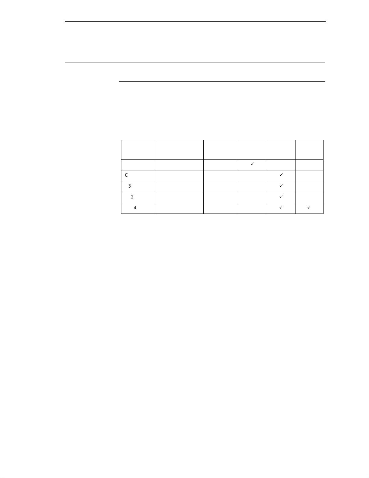
The LineJet Printer Family
Table 1. The LineJet Printer Family
Model
Number
C3201D LineJet 500P 500 lpm
C3202D LineJet 500Q 500 lpm
C3204D LineJet 1000Q 1000 lpm
C3205D LineJet 1500Q 1500 lpm
C5640D LineJet 1500Q 1500 lpm
Nameplate Print Speed Pedestal Cabinet
ä
ä
ä
ä
ää
Power
Stacker
Most line matrix printers have specialized architectures, which enable the
printer to emulate, or behave like, another printer. These specialized
architectures are restricted. The LineJet printer, however, introduces an open
architecture concept that is not available on any other line matrix printer.
The LineJet printer offers the standard emulation of Hewlett-Packard’s Printer
Control Language, PCL Level II, to allow easy online programming
capabilities and compatibility with Hewlett-Packard systems.
Additionally, the LineJet printer offers the following three emulations as part of
®
its LinePrinter Plus grouping: the Proprinter
III XL, Epson® FX-1050, and PSeries emulations. No matter what emulation is configured, your printer is
very easy to use. The message display and indicator on the control panel
communicate with you directly and clearly. You can select every function on
your printer at the control panel, or you can send commands from the host
computer.
15
Page 16
Chapter 1 Printer Overview
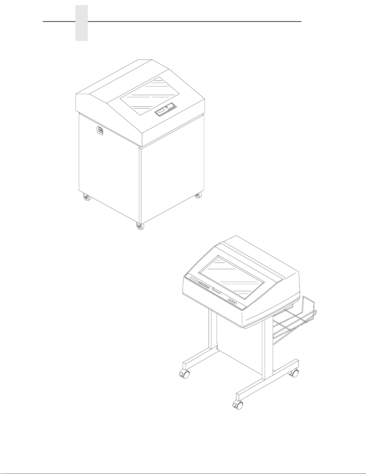
C3202D
C3204D
C3205D
C5640D
16
C3201D
Figure 1. The LineJet Printers
Page 17

Taking Care of Your Printer
Taking Care of Your Printer
Your printer will produce high quality print jobs if it is well taken care of.
Periodic cleaning, handling the printer properly, and using the correct printer
supplies, such as paper and ribbons, will ensure optimum performance.
Chapter 5 explains how to clean the printer, and printer supplies are listed in
Appendix A.
Whenever it is necessary to service the printer, remember these important
maintenance concepts:
• Use only the ribbons specified in Appendix A. Use of incorrect ribbons
can lead to ink migration problems, degraded print quality, and expensive
damage to the printer.
• Incorrect closure of the forms thickness lever can lead to smearing,
degraded print quality, paper jams, and damage to the platen and shuttle
assembly. Never close the forms thickness lever too tightly.
• Excessive printing outside of the boundaries of the paper will degrade
print quality and cause hammer bank damage. Never print outside of the
paper width.
Standard Features
All of the printers offer a wide range of horizontal and vertical dot densities,
operate quietly, and can load an emulation very easily. Other features are
specified in the following se ctions.
Host Computer Interfaces
The following host computer interface choices are available:
• Centronics
• RS-232 serial interface
• RS-422 serial interface
• Bi-Tronics
• Ethernet (optional)
Printer Emulations
The following printer emulations (or protocols) are selectable at the control
panel:
• HP
• LP Plus, which consists of:
®
Printronix P-Series
Epson FX-1050
IBM
®
®
PCL-II (the default)
®
Proprinter III XL
• Code V (optional)
Each emulation provides a different set of configuration menus, control codes,
and character sets.
17
Page 18

Chapter 1 Printer Overview
Output Control
Depending on the active emulation, the printers have the following output
control features:
• Four modes for printing text:
1. Correspondence (High Density)
2. Data Processing (DP) (Standard Density)
3. Sparse (high speed) (Sparse Density)
4. OCR A and OCR B
• Selectable forms length and width
• Character attribute specification:
1. Selectable pitch: normal, expanded, and compressed
2. Emphasized (shadow) printing
3. Automatic underlining and overscoring
4. Superscript and subscript printing
5. Double high and wide printing
• Resident multinationa l cha racte r se ts and bar codes
Graphics and V ertical Formatting
Several graphics and vertical formatting features are available:
• Built-in graphics generator s :
1. IBM Proprinter III XL bit-image graphics
2. Epson FX-1050 dot graphics mode
3. P-Series Plot
4. PCL raster graphics
• Programmable electronic vertical formatting provides rapid vertical paper
movement to specified lines for printing repetitive and continuous forms.
You can choose from the following methods:
1. Vertical tabbing in Proprinter III XL and Epson FX emulation modes
2. Electronic Vertical Format Unit (EVFU) in P-Series emulation mode
3. PCL vertical forms control (VFC)
Built-in Diagnostic Tools
The following diagnostic tools are provided with the printer:
• Comprehensive diagnostic self-tests permanently stored in the printer
• Configuration printout
18
• Data stream hex code printout
• Symbol set printout
Page 19

Graphics Options
Graphics Options
The Code V emulation allows you to create and store forms, generate logos,
bar codes, expanded characters, and create other graphics. Alphanumerics
and bar code data are added as the form is printed.
This emulation is available as a customer-installed option. For more
information, contact your authorized Hewlett-Packard representative.
Protocols and Emulations
A
protocol
printer and its host computer. These rules consist of codes which manipulate
and print data and allow for machine-to-machine communication. A printer
and its host computer must use the same protocol.
Most impact printers use single ASCII character codes to print text, numbers,
and punctuation marks. Some characters, both singularly and in groups of two
or more, are defined as control codes. Control codes instruct the printer to
perform specific functions, such as underlining text, printing subscripts,
setting page margins, etc. The main difference between most printer
protocols is in the characters used to create control codes and the ways in
which these characters are formatted.
is a set of rules governing the exchange of information between the
When the printer executes the character and control codes of a particular
printer protocol, it is “emulating” that printer. If the printer uses the Proprinter
III XL protocol, for example, it is emulating an IBM Proprinter III XL printer. If
the printer is using the Epson FX-1050 printer protocol, for example, we can
also say it is in Epson FX-1050 emulation mode. As used in this manual,
protocol
and
emulation
mean the same thing.
19
Page 20
Chapter 1 Printer Overview
Line Matrix Printing
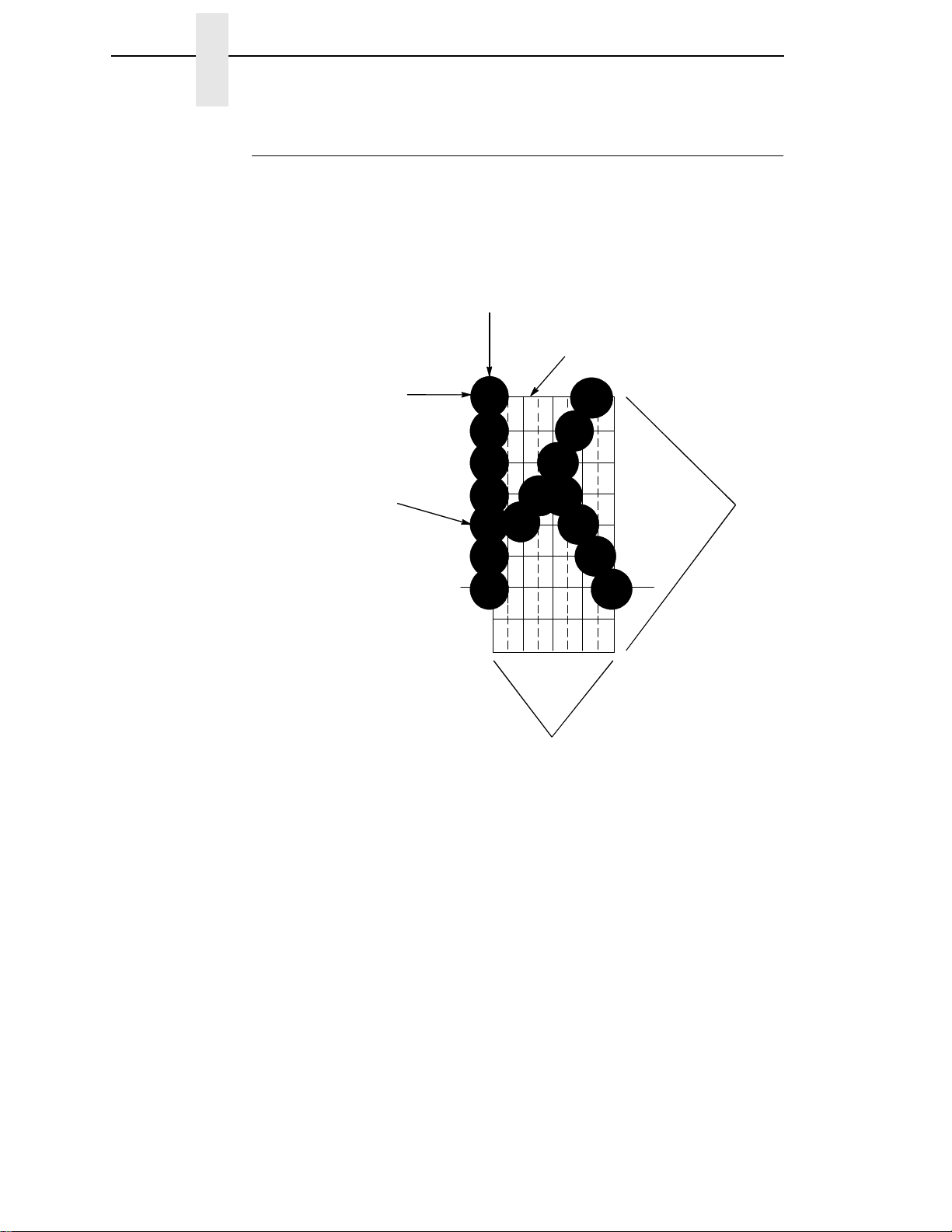
Your printer is an impact printer; it creates characters by printing ink dots on
paper. The dots are printed on an invisible matrix mapped in printer memory.
(See Figure 2.) Dot impressions are made by an array of steel hammers
mounted on a rapidly oscillating shuttle. The hammers strike the paper
through a moving ink ribbon.
Dot Row
Ink dots formed by
hammer tips.
Dot Column
Matrix visible only to
the printer
Character Row
20
Character Column
Figure 2. Dot Matrix Character Formation
Serial matrix printers use a moving printhead with pins to form single
characters sequentially along the printed line. Unlike serial matrix printers, the
LineJet printer is a
line matrix
printer. Line matrix printers divide every
printable line into horizontal dot rows, then print a dot row of the entire line at
every lateral sweep of the shutt le.
During each sweep of the shuttle, hammers are activated to print dots at the
required positions in the dot row. When the shuttle reaches the end of a
sweep, it reverses direction, the paper advances one dot row, and the
hammers print the next row of dots as the shuttle sweeps in the opposite
direction, as shown in Figure 3.
Page 21
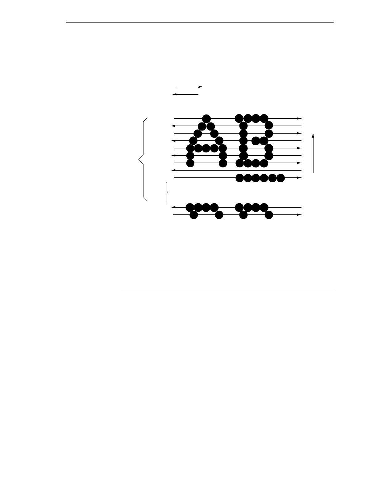
Printing Speed
After a line of characters is printed, the paper advances to the first dot row of
the next print line. This creates a number of blank rows between lines of
characters, depending on the print mode and line spacing you selected.
Direction of Shuttle Movement
Dot
Row Start
1
2
3
One
Text
Line
4
5
6
7
8
9
*
**
Paper
Feed
Direction
10
11
Number of rows is determined by line spacing.
n
1
2
This row is used only for lowercase descenders.
*
This row is used for underlining and lowercase descenders.
**
Figure 3. Dot Matrix Line Printing
Printing Speed
The speed at which text prints is measured in lines per minute (lpm). This
speed is directly proportional to the number of dot rows required to produce a
character line, regardless of the number of characters in the line. More dot
rows are required to print lowercase characters with descenders;
consequently, those character lines print at a fractionally lower rate.
The printer also prints dot-addressable graphic images. The speed at which
graphics are plotted is measured in inches per minute (ipm). Unidirectional
plotting produces slightly better print quality and takes about twice as long as
bidirectional plotting. You can select either plotting mode from the control
panel.
Printing and plotting rates also vary according to the print mode you select.
Print mode refers to the way you instruct the printer to create characters. If,
for example, you select standard quality (data processing) mode, the printer
uses more dot rows to form characters than if you choose Sparse (high
speed) mode. Character formation and print speed are faster in Sparse mode
because the printer prints fewer dot rows to form characters. Vertical dot
density is a factor in printing speed.
Nominal printing rates are charted in Appendix A.
21
Page 22

Chapter 1 Printer Overview
22
Page 23

2 Configuring the Printer
Overview
Note
Configuration directly affects printer operation. Do not change the
configuration of your printer until you are thoroughly familiar with the
procedures in this chapter.
This chapter is a tutorial that explains how to configure the LineJet printer.
In order to print data, the printer must respond correctly to signals and
commands received from the host computer. Configuration is the process of
matching the printer’s operating characteristics to those of the host computer
and to specific tasks, such as printing labels, or printing on different sizes of
paper.
The characteristics that define the printer’s response to signals and
commands received from the host computer are called configuration
parameters.
A configuration consists of all the parameters under the Active Emulation,
Emulation, Maint/Misc., Host Interface, Printer Control and Diagnostics
menus. Chapter 3 describes the configuration submenus and their
parameters in more detail.
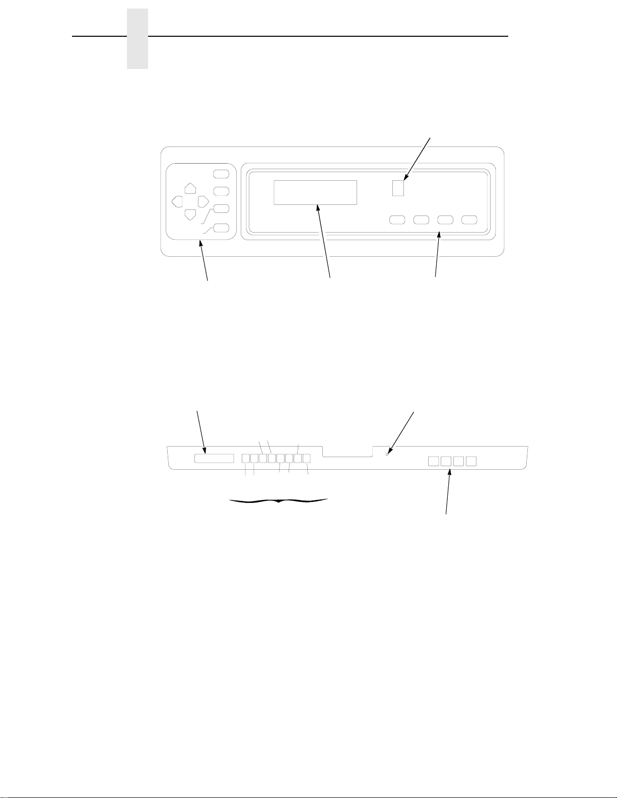
You configure the printer by pressing keys on the control panel (Figure 4) or
by sending control codes from the host computer. This chapter explains how
to change parameters and save, print, and load configurations with the control
panel. All of the keys are described in detail in the
Reference Guide
, shipped with each printer .
LineJet Printers: Quick
To configure the printer with control codes, refer to the appropriate
Reference Manual
.
Technical
23
Page 24
Chapter 2 Overview
UP
DOWN
L.P.I. ADJ
PAGE L. ADJ.
NEXTPREV
Cabinet Model
Status Indicator
CLEAR
SHIFT
SET TOF
ON LINE FF VIEWLF
ENTER
Secondary Keys
Message Display
Message Display
Pedestal Model
SET TOF
DOWNUP
LPI ADJ
CLEAR
SHIFT
NEXTPREV
ENTER
PAGE L. Adj
Secondary Keys
Figure 4. The Control Panels
Primary Keys
Status Indicator
ON LINE FF VIEWLF
Primary Keys
24
Page 25
OFFLINE
CONFIG.
CONTROL
page 47
Load Config.
Save Config.
Print Config.
Delete Config.
Power-up Config.
Protect Configs.
ETHERNET
PARAMS
page 87
IP Address
Gateway Address
Subnet Mask
MAC Address
Novell Protocol
NetBIOS Protocol
Novell Frame
PPM Port Number
PPM Port Timeout
ACTIVE
EMULATION
page 49
PCL-II*
LP PLUS
IGP/PGL & LP+
IGP/VGL & LP+
PRINTER
CONTROL
page 88
Unidirectional
PMD Fault
Slow Paper Slew
Power Saver Time
1
EMULATION
page 50
PCL-II*
LP PLUS
IGP/PGL & LP+
IGP/VGL & LP+
Printer Tests
Test Width
Paper Out Dots
System Memory
Print Statistics
2
DIAGNOS-
TICS
page 90
MAINT/MISC
page 78
Hex Dump Mode
Power-up State
3
Display Language
3
Power Stacker
RIBBON
MINDER
page 93
New Ribbon
Ribbon Action
Ribbon Size
Ribbon Adjust
Fault Action
4
HOST
INTERFACE
page 79
Bi-Tronics*
Centronics
Serial
Ethernet
1
Choices available are limited to the emulations installed
on the printer.
2
Appears only if LP Plus is the active emulation.
3
Appears only if the option is installed.
4
Appears only if installe d.
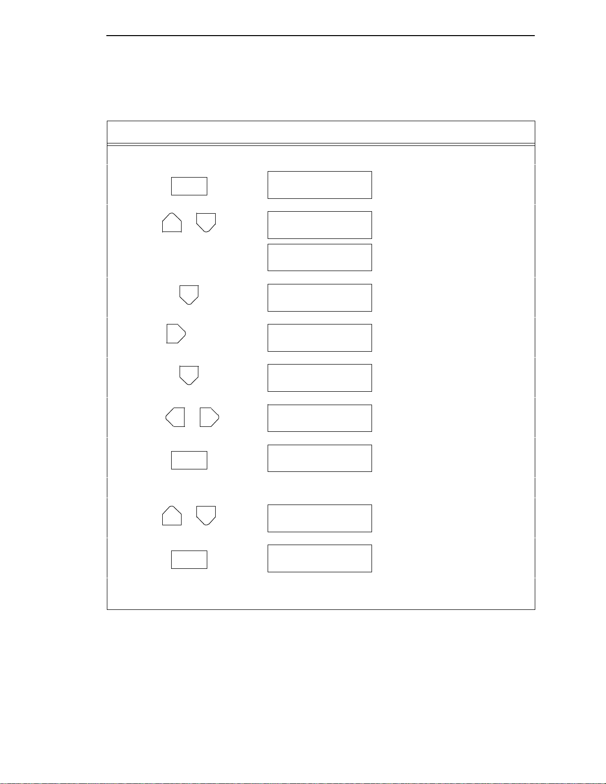
Figure 5. Configuration Menu Overview
To view options, press: > Down
= Up
< Next
; Prev
To select an option, press ENTER.
To return to main menu, press
CLEAR.
To exit menu, press ON LINE.
* = Default Setting
25
Page 26

Chapter 2 Overview
Operating Modes
The printer has two operating modes: online and offline. When the printer is
online, it is controlled by the host computer and prints data sent by the host
computer. If the printer is offline, communication with the host is interrupted
so you can load paper, change ribbons, or test and configure the printer.
You activate configuration settings with the ENTER key, which “enters” your
new setting into printer memory. An asterisk (*) after a displayed setting
shows it is entered into memory.
If pressing ENTER to select a parameter produces no result, press DOWN to
move to the next lower level. For example, if you press ENTER while
“CONFIG. CONTROL/ Print Config.” displays, nothing will happen because
another level exists below this selection. Press DOWN and the “Current”
option displays. To cycle through the choices (Current, Factory, Power-up,
etc.), press the NEXT or PREV keys. Press ENTER and the selected
configuration will print .
The Configurations
A configuration consists of a group of parameters, such as line spacing, forms
length, etc. Your printer contains the following configurations:
• The factory default configuration. It can be loaded, but it cannot be
altered. All of the parameters and their values are listed on page 28.
• Eight configurations that you can customize for unique print job
requirements. Creating customized configurations is explained on page
30.
Locking and Unlocking the ENTER Key
To make configuration changes, you must unlock the ENTER key. With the
printer offline, raise the printer cover and press the UP and DOWN keys
simultaneously. The message display will show this message for about a
second:
ENTER SWITCH
UNLOCKED
When you lock the ENTER key, your configuration settings are fixed and
cannot be altered. Locking secures your settings.
With the printer offline, raise the printer cover and press the UP and DOWN
keys simultaneously to lock the ENTER key. The message display will show
this message briefly:
26
ENTER SWITCH
LOCKED
Page 27

Changing and Saving Parameter Settings
Changing and Saving Parameter Settings
You can change a parameter setting, such as line spacing or forms length, by
pressing keys on the control panel or by sending emulation control codes in
the host data stream. The
about control codes.
When you change a parameter, it is active as long as the printer is on. This is
true whether you used the control panel or sent a control code from the host.
If you use the control panel, you can save the parameters as a customized
configuration. A configuration consists of a group of parameters. A saved
configuration will not be lost if you turn off the printer.
You can change a parameter with a control code, but to save the parameter
setting you must use the control panel.
Control codes override control panel parameters. For example, if you set the
line spacing to 6 lpi with the control panel, and application software later
changed this to 8 lpi with a control code, the control code setting overrides the
control panel setting.
Technical Reference Manuals
provide information
The 8 lpi parameter is effective as long as the printer is on. If you turn off the
printer, the 8 lpi parameter will be erased. To save the parameter, you must
use the control panel and save it as a configuration.
You can save up to eight configurations.
Changing parameters is discussed on page 30, saving configurations is
discussed on page 32.
27
Page 28

Chapter 2 Overview
Factory Default Configuration Values
The factory default values are permanently stored in memory as a
configuration. They cannot be modified or erased.
ACTIVE EMULATION PCL-II
PCL-II
LP PLUS
Primary Char. set
ID 0
Symbol Set Roman-8(8U)
Pitch 10.00
Density Data Processing
Second Char. set
ID 0
Symbol Set Roman-8(8U)
Pitch 10.00
Density Data Processing
Page Length Rep. Inches/Page
Max. Line Width 13.2 inches
Graphics Density 60 DPI
Perforation Skip Disable
Display Functns Disable
Line Terminator
LF After CR Disable
CR After LF Disable
CR after FF Disable
CR After VT Enable
PTX Linefeed Disable
LPI Adjust 6 LPI
Page L./Lines 66 Lines
Page L./Inches 11.0 Inches
Config. Print
Symbol Set Print
Reset Cmd CFG Ld Power Up Config
Printer Protocol
P-Series
Control Code 06 8.0 LPI
Control Code 08 Elongated
Define CR Code CR = CR
Auto LF Disable
Overstrike Enable
Define LF code LF = CR + LF
Select SFCC 1
EVFU Select Enable
Alt. Set 80-9F Control Code
Character Set
IBM PC
Primary Subset ASCII (USA)
Extended Subset Code Page 437
SFCC d command Even dot plot
CPI/LPI Select
Select CPI 10.0 CPI
Select LPI 6.0 LPI
Font Attributes
Typeface Data Processing
Prop. Spacing Disable
Bold Print Disable
Italic Print Disable
Slashed Zero Disable
Page Format
Form Length
Abs. Length IN 11.0 inches
28
Page 29

Factory Default Configuration Values
Abs. Length MM 279.4 mm
Funct. of lines 66 lines
Form Width
Abs. Width IN 13.6 inches
Abs. Width MM 345.4 mm
Function of CPI 136 characters
Margins
Left Margin 0 columns
Right Margin 0 columns
Bottom Margin 0 lines
Perforation Skip Disable
MAINT / MISC
Hex Dump Mode Disable
Power-up State Online
Display Language English
Power Stacker Enable
HOST INTERFACE
Bi-Tronics
Prime Signal Disable
TOF Action Reset
Buffer Size in K 1
ETHERNET PARAMS
IP Address xxx.xxx.xxx.xxx
Gateway Address xxx.xxx.xxx.xxx
Subnet Mask xxx.xxx.xxx.xxx
MAC Address hhhhhhhhhhhh
Novell Protocol Enable
NetBIOS Protocol Enable
Novell Frame Auto Sensing
PPM Port Number 3001
PPM Port Timeout 32 seconds
PRINTER CONTROL
Unidirectional Disable
PMD Fault Enable
Slow Paper Slew Disable
Power Saver Time 15 min
DIAGNOSTICS
Printer Tests Shift Recycle
Test Width Full Width
Paper Out Dots 40 dots
System Memory 4 Megabytes
Print Statistics
On: x.x Hrs
Print: x.x Hrs
Print Strokes x
Print Lines x
11 inch Pages X
RIBBONMINDER
New Ribbon
Ribbon Action Disable
Ribbon Size 60 yards
Ribbon Adjust 0
Fault Action New Ribbon
1
Default Ribbon Size for pedestal models is 60 yards.
Default Ribbon Size for cabinet models is 100 yards.
1
29
Page 30
Chapter 2 Changing Parameters
ON LINE
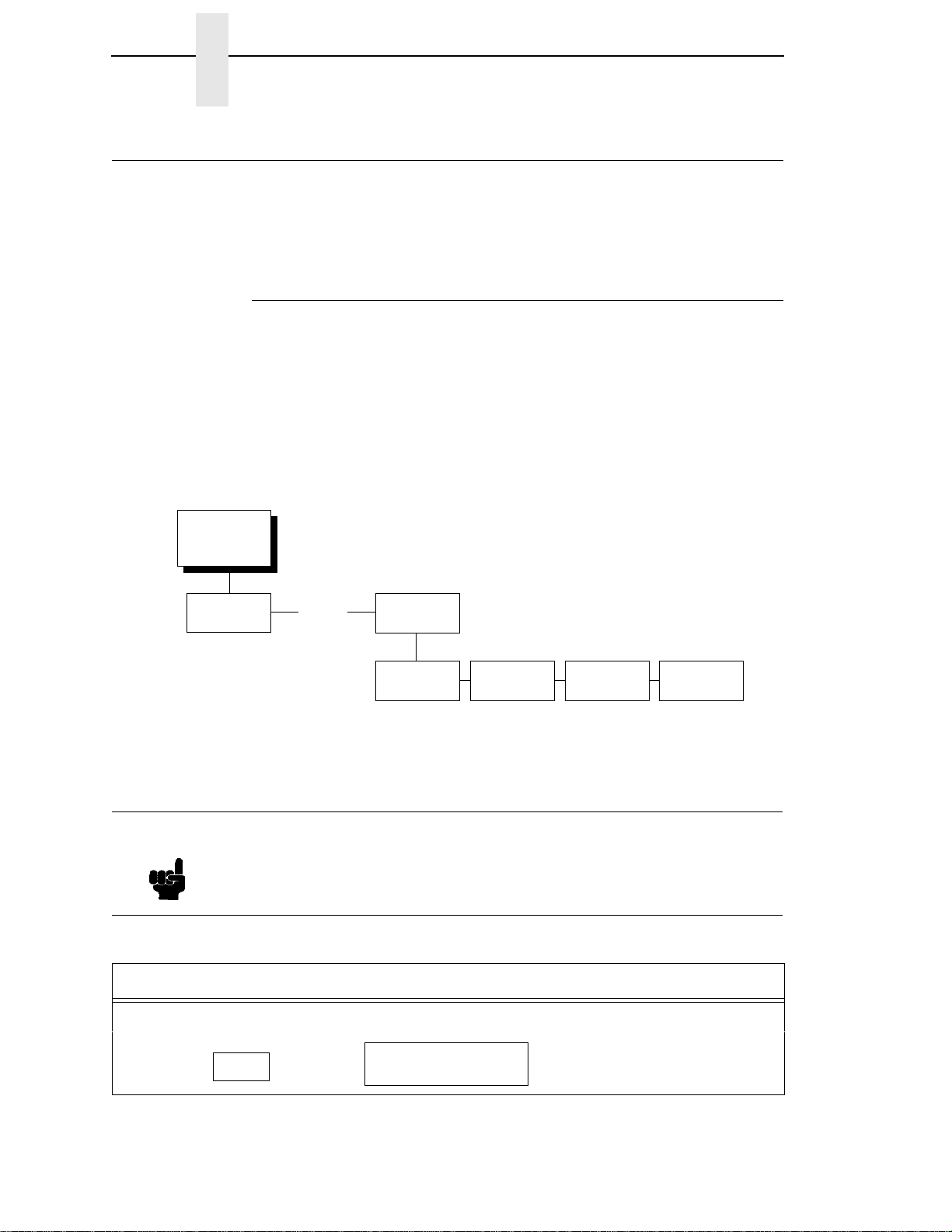
Changing Parameters
A configuration consists of several parameters. The factory configuration is
PCL-II emulation using the Bi-tronics interface. You can keep this
configuration to print your jobs, or if your print job requires a different setting,
such as a serial interface, follow the steps on the next page.
Example
Setting Unidirectional is provided as an example. Use this example as a basic
guideline to move throughout the configuration menu and change other
parameters.
Figure 5 on page 25 shows the top level of the configuration menu. The
submenus are shown in Chapter 3.
If the configuration has already been changed and you do not know what the
current configuration is, print a copy (page 34). Then decide if you must
change any parameters.
Note
OFFLINE
CONFIG.
CONTROL
* = Factory Default
. . .
PRINTER
CONTROL
Unidirectional
Disable*
Enable
PMD Fault
Enable*
Disable
Slow Paper
Slew
Disable*
Enable
Power Saver
Time
15* - 60 Min.
Instant
Once you change active emulations, any changes to the previously
selected emulation will be gone unless they have been saved.
Table 2. Parameter Change Example Procedure
Step Key Result Notes
1. Make sure the printer is on. Raise the printer cover.
2.
OFFLINE
CONFIG. CONTROL
30
Page 31

Table 2. Parameter Change Example Procedure (continued)
+
UNTIL
OR
ENTER
UNTIL
UNTIL
+
ON LINE
Step Key Result Notes
Example
3. Allows you to make configuration
ENTER SWITCH
UNLOCKED
changes.
OFFLINE
CONFIG. CONTROL
4.
OFFLINE
PRINTER CONTROL
5.
PRINTER CONTROL
Unidirectional
6.
Unidirectional
Disable*
7. Cycle through the choices.
Unidirectional
Enable
8. An asterisk (*) indicates this
Unidirectional
Enable*
choice is active.
TO SAVE YOUR CHANGES AS A CONFIGURATION THAT IS STORED IN MEMORY:
1.
OFFLINE
PRINTER CONTROL
2.
OFFLINE
CONFIG. CONTROL
3. Go to the CONFIG. CONTROL submenu Save Config. option, as described on page
33, step 4.
TO USE THE CURRENT CONFIGURATION WITHOUT SAVING:
1.
2.
ENTER SWITCH
LOCKED
ONLINE
3. On cabinet models, close the printer cover. The printer is ready for operation. All
parameters are effective as long as the printer is on. When you turn off the printer, the
parameters will be erased from memory.
31
Page 32

Chapter 2 Changing Parameters
Saving Your New Configuration
CONFIG.
CONTROL
* = Factory Default
Load Config.
Save Config. Print Config.
1
2
3
4
5
6
7
8
Delete Config.
Power-Up
Config.
Protect
Configs.
A configuration must be saved in order to load it later. You can save up to
eight configurations to meet different print job requirements. For example:
Config 1: Selects Standard density, 10 CPI, 6 LPI, 11-inch forms
Config 2: Selects Sparse density, 10 CPI, 8 LPI, 8-inch forms
The configurations are saved and stored in memory; they will not be lost if you
power off the printer. Later, you can load one of the configurations for a
specific print job. This eliminates the need to change settings (LPI, forms
length etc.) for each new job. See page 36 about loading configurations. You
may want to print your configurations (page 34) and store them in a safe
place, such as inside the printer cabinet.
If you are going to change and save parameters for both the PCL-II and
LinePrinter Plus emulations, remember to save the changes for the PCL-II
emulation before you select LP Plus as the active emulation (page 49) or vice
versa. Once you change active emulations, any changes to the previously
selected emulation will be erased unless they have been saved.
32
If you do not save your configuration before you turn off the printer, all of the
new parameters will be erased. When you turn the printer on again, the
power-up configuration will load. If no configurations have been designated as
the power-up configuration, the factory configuration will load.
If the Protect Configs. parameter is enabled, the new configuration will not be
saved unless the existing configuration has been deleted. See page 42 for
details.
Page 33

Saving Your New Configuration
ON LINE
+
UNTIL
OR
ENTER
UNTIL
+
ON LINE
Table 3. Saving Configurations
Step Key Result Notes
1. If you are already in the configuration menu, go to step 5.
2.
OFFLINE
CONFIG. CONTROL
3. Allows you to make configuration
ENTER SWITCH
UNLOCKED
changes.
OFFLINE
CONFIG. CONTROL
4.
CONFIG. CONTROL
Load Config.
5.
CONFIG. CONTROL
Save Config.
6.
Save Config.
1*
7. Press until the desired number
Save Config.
2
(1-8) displays.
NOTE: Do not turn off the printer while save is in progress because you might lose your
configuration.
8. The configuration is now saved in
9.
Save Config.
2*
CONFIG. CONTROL
memory. (In this case, config. 2.)
Save Config.
NOTE: It is recommended you print the configuration. Go to page 35, step 5. If you decide not
to print the configuration, then continue with the following steps.
10. Locks the ENT ER key.
11.
ENTER SWITCH
LOCKED
ONLINE
12. Close the printer cover. The printer is ready for operation.
33
Page 34

Chapter 2 Changing Parameters
Printing the Current Configuration
CONFIG.
CONTROL
* = Factory Default
Note
Load Config.
Save Config. Print Config.
Current*
Factory
Power-Up
All
1
2
3
4
5
6
7
8
Delete Config.
Power-Up
Config.
Protect
Configs.
The configuration printout lists the stored parameters. You can print any or all
of the configurations shown above. Configurations 1-8 are the customized
configurations.
To print a configuration, follow the procedure in Table 4.
It is recommended you print all of the configurations and store them in a
safe place, such as inside the printer cabinet, for future reference.
34
Page 35
Printing the Current Configuration
ON LINE
+
UNTIL
OR
ENTER
+
ON LINE
Table 4. Printing Configurations
Step Key Result Notes
1. Make sure the printer is on. Raise the printer cover.
2.
OFFLINE
CONFIG. CONTROL
3. Allows you to make configuration
ENTER SWITCH
UNLOCKED
changes.
OFFLINE
CONFIG. CONTROL
4.
CONFIG. CONTROL
Load Config.
5.
CONFIG. CONTROL
Print Config.
6.
Print Config.
Current*
7. Press until the desired option
8. The configuration listing begins
Print Config.
All
OFFLINE
CONFIG. CONTROL
displays.
printing.
9. Carefully tear off the configuration printout.
10. Locks the ENT ER key.
11.
ENTER SWITCH
LOCKED
ONLINE
12. Close the printer cover. Store the printout in a safe place. The printer is ready for
operation.
35
Page 36

Chapter 2 Changing Parameters
Loading Configuration Values
CONFIG.
CONTROL
* = Factory Default
Note
Load Config.
0*
1
2
3
4
5
6
7
8
Save Config. Print Config.
Delete Config.
Power-Up
Config.
Protect
Configs.
You can load any of the eight customized configurations or the factory default
configuration, Configuration 0. Its list of parameters begins on page 28.
The loaded configuration remains active as long as the printer is on. If you
power off the printer, the power-up configuration will load when power is
turned back on. Any of the eight customized configurations can be designated
as the power-up configuration.
The procedure in Table 6 on explains how to select the power-up
configuration. If you do not set a power-up configuration, the factory default
configuration will load if you power the printer off and then back on.
A configuration must be saved first in order to load it.
36
Page 37

Loading Configuration Values
ON LINE
+
OR
ENTER
+
ON LINE
Table 5. Loading Configurations
Step Key Result Notes
1. Make sure the printer is on. Raise the printer cover.
2.
OFFLINE
CONFIG. CONTROL
3. Allows you to make configuration
ENTER SWITCH
UNLOCKED
changes.
OFFLINE
CONFIG. CONTROL
4.
CONFIG. CONTROL
Load Config.
5.
Load Config.
1*
6. Press until the desired number
7. Displays for about a second.
Load Config.
4
Loading Saved
(1-8) displays.
Configuration
Load Config.
4*
The printer has loaded the
configuration.
8. Locks the ENTER key.
ENTER SWITCH
LOCKED
9.
ONLINE
10. Close the printer cover. The printer is ready for operation.
37
Page 38

Chapter 2 Changing Parameters
The Power-Up Configuration
CONFIG.
CONTROL
* = Factory Default
Load Config.
When you power on the printer for the first time, it loads configuration 0, the
factory default configuration.
If you save a configuration, such as configuration 1, and turn the power off
and then back on, the printer will load the designated power-up configuration,
not the last saved configuration.
For your convenience, you can specify which configuration (0-8) should be
the power-up configuration.
Save Config. Print Config.
Delete Config.
Power-Up
Config.
0*
1
2
3
4
5
6
7
8
Protect
Configs.
38
Page 39

The Power-Up Configuration
ON LINE
+
UNTIL
OR
ENTER
+
ON LINE
Table 6. Setting The Power-Up Configuration
Step Key Result Notes
1. Make sure the printer is on. Raise the printer cover.
2.
OFFLINE
CONFIG. CONTROL
3. Allows you to make configuration
ENTER SWITCH
UNLOCKED
changes.
OFFLINE
CONFIG. CONTROL
4.
CONFIG. CONTROL
Load Config.
5.
CONFIG. CONTROL
Power-Up Config.
6.
Power-Up Config.
0*
7. Press until the desired number
8. The printer has selected the
Power-Up Config.
6
Power-Up Config.
6*
(1-8) displays.
desired configuration.
9. Locks the ENTER key.
ENTER SWITCH
LOCKED
10.
ONLINE
11. Close the printer cover. The printer is ready for operation.
39
Page 40

Chapter 2 Changing Parameters
Deleting Configurations
CONFIG.
CONTROL
* = Factory Default
Load Config.
Save Config. Print Config.
Delete Config.
1*
2
3
4
5
6
7
8
Power-Up
Config.
Protect
Configs.
You can delete any of your customized configurations. You cannot, however,
delete the configuration 0, which is the factory preset configuration.
The Protect Configs. parameter must be set to disable before you may delete
a configuration (see page 42). Once you delete a configuration the Protect
Configs. parameter automatically returns to enable.
40
Page 41

Deleting Configurations
ON LINE
+
UNTIL
OR
ENTER
+
ON LINE
Table 7. Deleting Configurations
Step Key Result Notes
1. Make sure the printer is on. Raise the printer cover.
2.
OFFLINE
CONFIG. CONTROL
3. Allows you to make configuration
ENTER SWITCH
UNLOCKED
changes.
OFFLINE
CONFIG. CONTROL
4.
CONFIG. CONTROL
Load Config.
5.
CONFIG. CONTROL
Delete Config.
6.
Delete Config.
1*
7. Press until the desired number
8. The printer has de leted the
Delete Config.
3
Deleting Configuration
(1-8) displays.
selected configuration.
Delete Config.
3*
9. Locks the ENTER key.
ENTER SWITCH
LOCKED
10.
ONLINE
11. Close the printer cover. The printer is ready for operation.
41
Page 42

Chapter 2 Changing Parameters
Protecting Your Configurations
CONFIG.
CONTROL
* = Factory Default
Load Config.
Save Config. Print Config.
Delete Config.
Power-Up
Config.
Protect
Configs.
Disable*
Enable
In order to save or delete a configuration you must set the Protect Configs.
option to disable. The Protect Configs. selection will automatically return to
enable once a configuration is saved or deleted.
42
Page 43

3 The Configuration Menus
Overview
Once you have familiarized yourself with the configuration process using the
tutorial information in Chapter 2, you are ready to complete your configuration
of the printer.
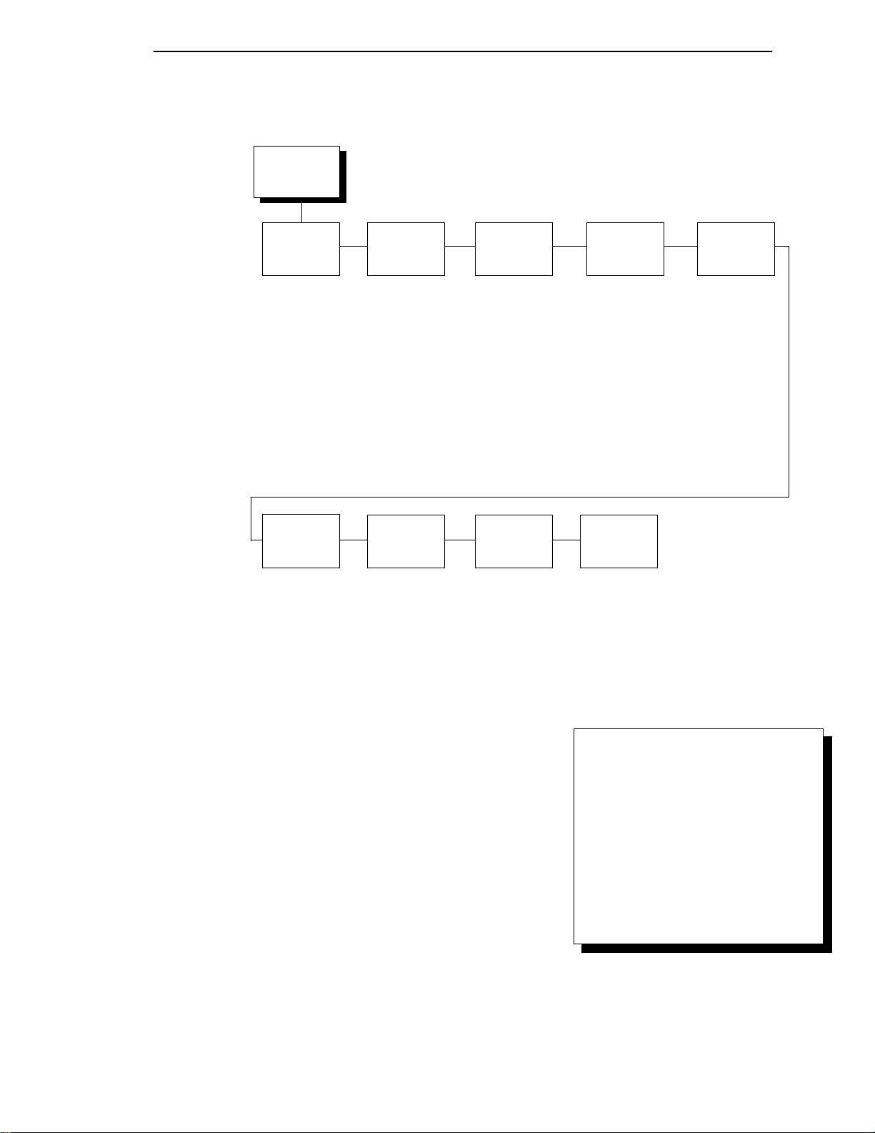
This chapter provides descriptions for each parameter provided by the
configuration menus. Figure 6 shows the configuration main menu and its first
level parameters. The remainder of this chapter includes illustrations of many
additional submenus and parameters nested beneath each of the main menu
options.
43
Page 44

Chapter 3 Overview
OFFLINE
CONFIG.
CONTROL
(see page 47)
Load Config.
0* - 8
Save Config.
1* - 8
Print Config.
Current*
Factory
Power-Up
All
1 - 8
Delete Config.
1* - 8
Power-Up Config.
0* - 8
Protect Configs.
Disable*
Enable
ACTIVE
EMULATION
(see page 49)
PCL-II*
LP PLUS
IGP/PGL & LP+
IGP/VGL & LP+
1
EMULATION
(see page 50)
PCL-II*
LP PLUS
IGP/PGL & LP+
IGP/VGL & LP+
MAINT/MISC
(see page 78)
Hex Dump Mode
Disable*/Enable
Power-Up State
Online*/Offline
Display Language
English*
German
French
Italian
Spanish
Power Stacker
Enable*/Disable
2
Continued on
the next page
NOTES:
1
Choices available are limited to the emulations
configured with the printer.
2
Appears only if the power stacker option is installed.
Figure 6. Configuration Menu Overview
44
To view options, press: > Down
= Up
< Next
; Prev
To select an option, press ENTER.
To return to main menu, press
CLEAR.
To exit menu, press ON LINE.
* = Default Setting
Page 45

HOST
INTERFACE
(see page 79)
Bi-Tronics*
Prime Signal
Disable*/Enable
TOF Action
Reset*/Do Nothing
Buffer Size i n K
1* (1-16)
Centronics
Data Bit 8
Enable*/Disable
PI Ignored
Enable*/Disable
Data Polarity
Standard*/Inverted
Resp. Polarity
Standard*/Inverted
Busy On Strobe
Enable*/Disable
Latch Data On
Leading*/Trailing
Prime Signal
Disable*/Enable
Buffer Size i n K
1* (1-16)
Serial
Interface Type
RS-232*/RS-422
Data Protocol
XON/XOFF*
ETX/ACK
ACK/NAK
DTR
Baud Rate
600, 1200, 2400
4800, 9600*,
19200, 38400
Word Length
8* or 7
Stop Bits
1* or 2
Parity
None*, Odd
Even, Mark
Sense
Data Term Ready
True*
On-Line and BNF
Off-Line or BF
False
Request to Send
On-Line and BNF*
Off-Line or BF
False
True
Buffer Size in K
1* (1-16)
Ethernet
Buffer Size in K
1* (1-16)
ETHERNET
PARAMS
(see page 87)
IP Address
xxx.xxx.xxx.xxx
Gateway Address
xxx.xxx.xxx.xxx
Subnet Mask
xxx.xxx.xxx.xxx
MAC Address
hhhhhhhhhhhh
Novell Protocol
Enable*/Disable
NetBIOS Protocol
Enable*/Disable
Novell Frame
Auto Sensing*
Ethernet II
Ethernet 802.2
Ethernet 802.3
802.2 Snap
PPM Port Number
3001*
(0-65535)
PPM Port Timeout
32 Seconds*
(1-255)
PRINTER
CONTROL
(see page 88)
Unidirectional
Disable*
Enable
PMD Fault
Enable*
Disable
Slow Paper Slew
Disable*
Enable
Power Saver Time
15 min.*
(0-60 min.)
DIAGNOSTICS
(see page 90)
Printer Tests
Shift Recycle*
All E’s
E’s + TOF
All H’s
All Underlines
All Black
Shuttle Slow
Shuttle Fast
Shuttle Only
Phase Printer
Paperout Adj.
Burnin Test
Print Error Log
Clear Error Log
E-Net Test Page
Test Width
Full Width*
80 col.
Paper Out Dots
40 dots*
(4-76 dots)
System Memory
x Megabytes
Print Statistics
On xx Hrs.
Print xx Hrs.
Print Strokes
Print Lines
11 Inch Pages
To view options, press: > Down
RIBBON
MINDER
(see page 93)
New Ribbon
Ribbon Action
Disable*
Display
Fault
Ribbon Size
60 yards*
(1-255)
Ribbon Adjust
0%*
(-99% to 99%)
Fault Action
New Ribbon*
Do Nothing
= Up
< Next
To select an option, press ENTER.
To return to main menu, press
CLEAR.
To exit menu, press ON LINE.
* = Default Setting
Figure 6. Configuration Menu Overview (continued)
; Prev
45
Page 46

Chapter 3 Overview
Configuration Main Menu
Brief descriptions follow for the first-level configuration menu options:
• CONFIG. CONTROL. These options allow you to save, print, load, and
delete entire sets of configuration parameters. These options are
described briefly in this chapter, and covered in detail in Chapter 2.
• ACTIVE EMULATION. You can select either Hewlett-Packard’s Printer
Control Language (PCL-II) or LP Plus.
If you select PCL-II, you can select the optional IGP
(Code V) emulations, if installed.
If you select LP Plus, you can select Epson FX, Proprinter XL, or PSeries.
• EMULATION. If PCL-II is the active emulation, PCL-II will display and you
can select its parameters for configuration.
If the optional IGP/PGL or Code V emulations are installed, you can
access their configuration parameters.
If LP Plus is the active emulation, Epson FX, Proprinter XL, and P-Series
configuration parameters are available.
• MAINT / MISC. These options provide miscellaneous functions, such as
printing a hex dump, selecting a display language, and choosing whether
the printer will power up offline or online.
®
/PGL® or IGP/VGL
• HOST INTERFACE. These options allow you to select the printer
interface depending on what type of interface cabling you installed while
setting up your printer. In addition to selecting an active interface, this
menu also allows you to configure several parameters for each interface.
• ETHERNET PARAMS. This option allows you to view and change the IP
Address, Gateway Address, and Subnet Mask. The MAC Address may
also be viewed. In addition, Novell and Printer Manager options can be
set.
• PRINTER CONTROL. These options allow you to select several
operating parameters for the printer, such as the speed at which paper
will advance when FF (Form Feed) is pressed.
• DIAGNOSTICS. These options include the printer’s diagnostic tests,
system memory, and print statistics.
• RIBBONMINDER. The options in this submenu allow you to enable the
™
RibbonMinder
feature and set its parameters.
46
Page 47

CONFIG. CONTROL
Menu
CONFIG.
CONTROL
Menu
Load Config.
0*
1
2
3
4
5
6
7
8
Save Config. Print Config.
1*
2
3
4
5
6
7
8
Current*
Factory
Power-Up
All
1
2
3
4
5
6
7
8
Delete Config.
1*
2
3
4
5
6
7
8
Power-Up
Config.
0*
1
2
3
4
5
6
7
8
Disable*
Enable
To view options, press: > Down
= Up
< Next
; Prev
To select an option, press ENTER.
To return to main menu, press
CLEAR.
To exit menu, press ON LINE.
Protect
Configs.
* = Default Setting
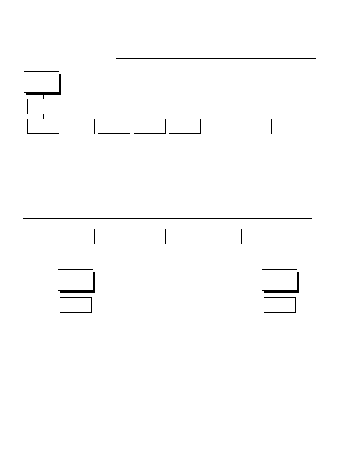
The CONFIG. CONTROL menu manages configurations, which are
groupings of parameter values that can be stored in printer memory. Brief
descriptions follow for each option.
Load Config.
The printer can store up to eight unique configurations in memory. This
parameter allows you to select and load a specific configuration.
Configuration 0 is the factory default; its parameters cannot be changed. It is
always available for loading. A fuller description and sample procedure for
using this option appears on page 36.
47
Page 48

Chapter 3 CONFIG. CONTROL
Save Config.
This option allows you to save up to eight unique configurations to meet
different print job requirements. This eliminates the need to change the
parameter settings for each new job.
The configurations are stored in memory. They will not be lost if you turn off
the printer. Configuration 0 is a factory-preset configuration, which can not be
changed or saved. See page 32 for a fuller description and sample procedure.
Note
If the Protect Configs. parameter is enabled, the new configuration will not
be saved unless the existing configuration has been deleted.
Print Config.
This option is used to print a listing of stored printer configurations. It is
recommended you store the configurations in a safe place for quick referral,
such as inside the printer if you have a cabinet model. A fuller description and
sample procedure is provided on page 34.
Delete Config.
You can delete one or all of your eight customized configurations.
Configuration 0 is a factory-preset configuration and cannot be changed or
deleted.
Power-Up Config.
You can specify which of the nine configurations (0-8) will be the power-up
configuration. The factory default for power-up is configuration 0. See page 38
for a fuller description and sample procedure.
48
Protect Configs.
You can specify whether or not a new configuration should overwrite an
existing configuration when you activate the Save Config. parameter.
• Disable. The default. The new configuration will overwrite the existing
configuration.
• Enable. The new configuration will not overwrite the existing
configuration, and the message “CONFIG. EXISTS / Delete First”
displays. You must delete the existing configuration (1-8) before trying to
save the new configuration.
Page 49

ACTIVE EMULATION
ACTIVE
EMULATION
Menu
PCL-II*
LP PLUS
IGP/PGL &
1
LP+
IGP/VGL &
1
LP+
To view options, press: > Down
= Up
< Next
; Prev
To select an option, press ENTER.
To return to main menu, press
CLEAR.
To exit menu, press ON LINE.
1
= if installed
* = Default Setting
The ACTIVE EMULATION menu determines what emulations are available.
• PCL-II. The default. The PCL-II emulation is active.
• LP PLUS. This option selects LinePrinter Plus as the active emulation. If
LP PLUS is the active emulation, you can select Epson, Proprinter III XL,
or P-Series as the printer protocol (see page 55).
• IGP/PGL & LP+ and IGP/VGL & LP+. The ACTIVE EMULATION
function also allows you to activate either the PGL or the Code V
emulation. There are two methods for selecting the desired emulation.
The first is by selecting the emulation directly from the printer menu. The
second is by sending a host command which will switch the emulation
automatically. See the appropriate
Technical Reference Manual
information on these command codes.
for more
Note
When changing from one IGP emulation to the other, the printer will load
the power-up configuration. Thus, any setting performed before selecting
those interfaces and not saved in flash memory will be lost.
For more information on IGP/PGL and Code V, see the appropriate
Technical Reference Manual.
In order to configure an IGP emulation, the IGP emulation must be
selected in the ACTIVE EMULATION menu. The IGP emulation that is not
selected will not appear in the EMULATION menu.
49
Page 50

Chapter 3 EMULATION
EMULATION
EMULATION
PCL-II*
(see page 51)
LP PLUS
(see page 55) (see page 66) (see page 71)
IGP/PGL &
1
LP+
IGP/VGL &
1
LP+
To view options, press: > Down
= Up
< Next
; Prev
To select an option, press ENTER.
To return to main menu, press
CLEAR.
To exit menu, press ON LINE.
1
= if installed
The EMULATION menu is the gateway to configure the emulations available
with the LineJet printer. The control codes for each of these emulations are
described in their respective
Technical Reference Manuals
* = Default Setting
.
PCL-II Emulation
50
Hewlett-Packard’s Printer Control Language that is compatible with HewlettPackard systems.
LP PLUS Emulations
• Epson FX. This LP Plus emulation is provided for compatibility with the
Epson FX-1050 printer control language.
• Proprinter XL. This LP Plus emulation is provided for compatibility with
the IBM Proprinter III XL printer control language.
• P-Series. This is the Printronix P-Series printer control language,
provided as part of LP Plus.
Optional Emulations
IGP/VGL (Code V) and IGP/PGL are optional graphics emulations. They can
be selected and configured only if you have purchased these options. PCL-II
must be the active emulation for Code V or IGP/PGL to operate.
Page 51
EMULATION
(from page 50)
PCL-II
PCL-II Submenu
PCL-II Submenu
* = Factory Default
Primary Char
Set
ID
0* - 109, xx
Symbol Set
(see below)
Pitch
10*, 12, 13.3
15, 16.67, 20
Density
Data Proc.*
NLQ
OCR-A
OCR-B
High Speed
PTX Linefeed
Disable*
Enable
Secondary
Char Set
ID
0* - 109, xx
Symbol Set
(see below)
Pitch
10*, 12, 13.3
15, 16.67, 20
Density
Data Proc.*
NLQ
OCR-A
OCR-B
High Speed
LPI Adjust
6 lpi*
8 lpi
Primary Char
Set
(from above)
Page Length
Rep.
Inches/Page*
Lines/Page
Page L. Lines
66*
(1-128)
Max. Line
Width
13.2 inches*
13.6 inches
Page L. Inches
11 inches*
(2-16 inches)
Graphics
Density
60 dpi*
70 dpi
Config. Print
Perforation
Skip
Disable*
Enable
Symbol Set
Print
Display
Functns
Disable*
Enable
Reset Cmd
CFG Ld
Disable*
Power-Up Config
Current Config
Factory Config
Secondary
(from above)
Line
Terminator
LF after CR
Disable*
Enable
CR after LF
Disable*
Enable
CR after FF
Disable*
Enable
CR after VT
Enable*
Disable
Char Set
Symbol Set
Roman-8(8U)*
Turkish-8(8T)
Arabic-8(8V)
Cyrillic(8R)
PC858 MtLi (13U)
MCText (12J)
Roman-9 (4U)
Latin 9 (9N)
Win 3.0 Latin-1 (9U)
Japan Postnet
Katakana Post
ASCII(0U)
Math Sym(0A/0M)
LineDraw(0B/0L)
IS0 Den/Nor(0D)
Roman Ext.(0E)
IS0UK(1E)
IS0 France(0F)
IS0 German(0G)
Hebrew(0H)
Japan ASCII(0K)
Katakana(1K)
Block Char(1L)
OCR-A(0O)
OCR-B(1O)
ISO Swe/Fin(0S)
ISO Spain(1S)
ISO Italian(0I)
ISO Portugu(4S)
Latin-1(0N)
Latin-2(2N)
Latin-5(5N)
Latin-6(6N)
Baltic(19L)
PC8 DanNor(11U)
PC8 Cd437(10U)
PC850 MtLi(12U)
PC851 LtGk(12G)
PC852 Lat2(17U)
PC Turkish(9T)
PC Hebrew(15H)
PC Lat/Ara(10V)
PC Cyrillic(3R)
Win3.1 Lat1(19U)
Win3.1 Lat-2(9E)
Win3.1 Lat-5(5T)
Math-8(8M)
PS Math(5M)
Greek 7(12N)
Postnet 4(15Y)
Postnet 11.25
Greek-8(8G)
Hebrew-8(8H)
Katakana-8(8K)
DEC 256 Greek
ELOT 928 Greek
Greek 3
ABY Greek
ABG Greek
ELOT 927 Greek
Greek 437
Greek 8859-7
Symbol Set
(identical to Primary
Character Set)
51
Page 52

Chapter 3 EMULATION
Primary Character Set
You can select one of 92 pre-defined character sets by ID (although character
sets range from 0 - 109, not all sets are available on the LineJet printer), or
you can select pitch, symbol set, and typeface individually. If the combination
you choose matches one of the 92 predefined sets, the ID submenu will
reflect that selection. If not, the ID menu will display “xx” to indicate that the
current character set does not match a pre-defined set. Set 0 is the default
and its attributes are 10 cpi, Data Processing typeface, and Roman 8 symbol
set.
Secondary Character Set
Your printer can store an additional character set. To toggle between them,
send the Shift In (Decimal 15, to select the Primary character set) or Shift Out
(Decimal 14, to select the Secondary character set).
Page Length Representation
• Inches/Page. All page length calculations are based on the inches
displayed on the panel.
• Lines/Page. All changes in LPI or density will be changed accordingly.
The length of the page is the number of lines per inch, or lpi.
For example, if the form in use is 82 lines at 6 lpi, the page is physically
13.67 inches. Since 13.67 inches is not selectable from the Length in
Inches menu, change the representation to lines, then set the number of
lines to 82. The inches menu will display 13.6 inches although the printer
internally keeps the exact form length of 13.67 inches.
Max. Line Width
Set the maximum line width at 13.2 inches (the default) or 13.6 inches.
Graphics Density
Graphics can be printed in 60 DPI (the default) or 70 DPI.
Perforation Skip
• Disable. Allows printing on page perforation.
• Enable. You may set up a skip-over margin. For example, a skip-over
margin of 1 inch allows a 1 inch margin at the bottom of the page.
Display Functions
• Disable. The default. Control characters are not printed.
52
• Enable. Control characters are printed before they get executed. This is a
useful debugging tool.
Page 53

PCL-II Submenu
Line Terminator
You can specify what will be used to indicate the end of a line. Four options
are available: LF after CR, CR after LF, CR after FF, and CR after VT. Each of
these options may be Enabled or Disabled independent of one another.
PTX Linefeed
• Disable. The default. Linefeed is to be performed as calculated from the
bottom of the graphics or barcode, thereby disrupting the vertical text
alignment.
• Enable. The Linefeed moves to the next line as calculated from the Top
of Form position, thereby retaining vertical text alignment. When printing
graphics or bar codes, you may want to set the PTX Linefeed parameter
to Enable to maintain text alignment.
PTX Linefeed Enabled PTX Linefeed Disabled
Note
LINE 1
LINE 2
LINE 3
Linefeed
LINE 1
LINE 2
LINE 3
Linefeed
LPI Adjust
This parameter lets you specify the lines per inch (lpi) values, 6 LPI (the
default) or 8 LPI.
Page Length Adjust/Lines
This parameter lets you set physical page length from 12 to 96 at 6 lpi, or 16
to 128 at 8 cpi. The default is 66 lines at 6 lpi.
If 6 lpi is selected, you will be able to scroll the menu to 128 (an invalid
length). However, when you press Enter to select this value, the menu will
return with the maximum lines for 6 lpi (i.e. 96 lines). Similarly, selecting
too few lines for 8 lpi will cause the menu to return with 16 lines.
Page Length Adjust/Inc hes
This parameter lets you set physical page length from 2 to 16 inches, in
increments of half an inch. The default is 11 inches.
Config. Print
This option prints the emulation’s parameters and the currently selected
values.
53
Page 54

Chapter 3 EMULATION
Symbol Set Print
This option prints a list of all the available sets. The character set number
prints to the left of the character set sample.
Reset Cmd CFG Ld
When the printer receives a host data stream reset command (ESC @ or
ESC[K) in addition to resetting printer variables, the selected configuration will
be loaded.
• Disable. The factory configuration is loaded when the reset command is
executed.
• Power-Up Config. The power-up configuration is loaded when the reset
command is executed.
• Current Config. The currently selected configuration is loaded when the
reset command is executed.
• Factory Config. The factory installed configuration is loaded when the
reset command is executed.
54
Page 55

EMULATION
(from page 50)
LP PLUS
LinePrinter+
LinePrinter+
Printer
Protocol
P-Series*
(see page 59) (see page 62) (see page 64)
Print Char. Set Font Attributes
Proprinter XL Epson FX
CPI/LPI Select
Select CPI
10.0 CPI*
12.0 CPI
13.3 CPI
15.0 CPI
17.1 CPI
20.0 CPI
Select LPI
6.0 LPI*
8.0 LPI
10.3 LPI
Typeface
Data Proc.*
NLQ
OCR-A
OCR-B
High Speed
NLQ Sans Serif
Prop. Spacing
Disable*/Enable
Bold Print
Disable*/Enable
Italic Print
Disable*
Forward Slant
Backward Slant
Slashed Zero
Disable*/Enable
Page Format
Form Length Form Width
Abs. Length IN
11.0* inches
(0.1-24)
Abs. Length MM
279.4* mm.
(0.1-609.6)
Funct. of Lines
66* lines
(1-192)
Reset Cmd
CFG Ld
Disable*
Power-Up Config
Current Config
Factory Config
Abs. Width IN
13.6* inches
(0.1-13.6)
Abs. Width MM
345.4* mm.
(0.1-345.4)
Funct. of CPI
136* Characters
(1-272)
Margins
Left Margin
0* columns
(0-369)
Right Margin
0* columns
(0-369)
Bottom Margin
0* lines
(0-451)
Perforation
Skip
Disable*
1/2 inch
2/3 inch
5/6 inch
1 inch
To view options, press: > Down
= Up
< Next
; Prev
To select an option, press ENTER.
To return to main menu, press
CLEAR.
To exit menu, press ON LINE.
* = Default Setting
55
Page 56

Chapter 3 EMULATION
Printer Protocol
Select the LinePrinter+ protocol you wish to use. Refer to the
LinePrinter Plus Technical Reference Manual
for more information.
PCL-II/
Print Char Set
When this selection is displayed and the ENTER key is pressed, the current
character set is printed.
CPI/LPI Select
This parameter lets you specify the characters per inch (cpi) and lines per
inch (lpi) values.
Font Attributes
Typefaces
• Data Processing. A general purpose font printing out at 120 dpi
horizontally and 72 dpi vertically. The width of the font will vary with each
cpi.
• NLQ. A high quality font printing at 180 dpi horizontally and 96 dpi
vertically. This font has serifs and the width of the font varies with the cpi.
• OCR-A / OCR-B. Optical character recognition fonts printing at 120 dpi
horizontally and 144 dpi vertically. Both fonts print only at 10 cpi.
• High Speed. A draft quality font printing at 120 dpi horizontally and 48 dpi
vertically. The width of the font varies with the cpi.
• NLQ Sans Serif. A high quality font printing at 180 dpi horizontally and 96
dpi vertically. This font prints without serifs. The width of the font varies
with the cpi.
Proportional Spacing
Each printed character is contained inside a character cell. The width of the
character cell includes the character and the space around the character.
• Disable. Each character cell is printed with the same width. Each column
in the printed text will line up.
• Enable. The width of each character cell varies with the width of the
character. For example, [i] takes less space to print than [m]. Using
proportional fonts generally increases the readability of printed
documents, giving text a typeset appearance.
56
Page 57

LinePrinter+
Bold Print
• Disable. Text is printed normally.
• Enable. Text is printed with a heavy line thickness.
Italic Print
• Disable. Text is printed normally.
• Forward Slant. Text is printed with a forward slant.
• Backward Slant. Text is printed with a backward slant.
Slashed Zero
This parameter allows you to print the numeral “0” with or without the slash.
This option applies to all character sets except OCR-A and OCR-B.
• Disable. Zero is printed without a slash.
• Enable. Zero is printed with a slash.
Page Format
Forms Length
Forms length is the number of lines that can be printed on a page. You can set
forms length in inches, millimeters (mm) or as a function of the current LPI
(lines per inch).
Forms Width
The forms width can be specified in inches, millimeters, or as a function of the
current CPI (characters per inch). The forms width set should not exceed the
actual paper width.
Margins
• Right Margin. Set in columns. Column zero is defined as the far right
edge of the page, and column numbering increments from right to left.
• Left Margin. Set in columns. Column zero is defined as the far left edge
of the page, and column numbering increments from left to right.
• Bottom Margin. Defined in lines, starting from line zero at the bottom of
the page and incrementing from the bottom up.
Perforation Skip
• Disable. Allows printing on page perforation.
• You may set up a skip-over margin of 1/2 inch, 2/3 inch, 5/6 inch, or 1
inch. For example, a skip-over margin of 1 inch allows a 1 inch margin at
the bottom of the page.
57
Page 58

Chapter 3 EMULATION
Reset Cmd CFG Ld
When the printer receives a host data stream reset command (ESC @ or
ESC[K) in addition to resetting printer variables, the selected configuration will
be loaded.
• Disable. The factory configuration is loaded when the reset command is
executed.
• Power-Up Config. The power-up configuration is loaded when the reset
command is executed.
• Current Config. The currently selected configuration is loaded when the
reset command is executed.
• Factory Config. The factory installed configuration is loaded when the
reset command is executed.
58
Page 59

Printer
Protocol
(from page 55)
P-Series
P-Series Emulation
P-Series Emulation
* = Factory Default
Character Set
(from above)
IBM PC*
Primary Subset
ASCII (USA)*
French
German
English
Danish
Swedish
Italian
Spanish
Japanese
French Canadian
Latin American
Norwegian
Danish II
Spanish II
Latin Am II
Extended Subset
Code Page 437*
Code Page 850
Control Code
Control Code 08Define CR
06
6.0 LPI
8.0 LPI*
Elongated*
Backspace
10.3 LPI
Select SFCC
1*
(0-7F hex)
EVFU Select Alt. Set 80-9F
Enable*
Disable
Multinational ECMA Latin 1
ASCII (USA)*
EBCDIC
Primary Subset
ASCII (USA)*
German
Swedish
Danish
Norwegian
Finnish
English
Dutch
French
Spanish
Italian
Turkish
Japanese
Extended Subset
Multinational*
Barcode 10 CPI
Mult. DP 10 CPI
Mult. DP 12 CPI
Mult. LQ 10 CPI
Greek DP 10 CPI
Greek DP 12 CPI
Greek LQ 10 CPI
Grap. DP 10 CPI
Grap. LQ 10 CPI
Sci. DP 10 CPI
Sci. DP 12 CPI
Sci. LQ 10 CPI
Code
CR = CR*
CR = CR + LF
Control Code*
Printable
DEC
Multinational
ASCII (USA)*
French
German
English
Norweg./Danish
Swedish
Italian
Spanish
Japanese
French Ca nadian
Dutch
Finnish
Swiss
Auto LF
Disable*
Enable
Character Set
(see below)
OCR-A
Latin 2 8859-2
DEC 256
Greek
ABG Greek
Overstrike Define LF
Code
Enable*
Disable
LF = CR + LF*
LF = LF
SFCC d
Command
Even dot plot*
Double High
OCR-B
Latin 2 852 Bulgarian
ELOT 928
Greek 3 ABY Greek
Greek
ELOT 927
Greek 437 Greek 8859-7
Greek
Polish POL1
PC 851 LtGk
Greek 7
Greek 8
59
Page 60

Chapter 3 EMULATION
Control Code 06
Control Code 06 defines the function of ASCII code hex 06 (ACK). You can
select an alternate line spacing of 6, 8 or 10.3 LPI.
Control Code 08
Control Code 08 defines the function of ASCII code hex 08 (BS). You can
define the code to output an elongated character or a backspace.
Define CR Code
This option controls the action of the printer when it receives a Carriage
Return code (hex 0D) from the host computer. If this feature is enabled, each
time the printer receives a Carriage Return, it inserts an additional Line Feed
code (hex 0A) into the data stream. Do not use this feature if the host
computer sends Line Feeds to the printer.
• CR = CR. Does not insert an extra Line Feed after each Carriage Return.
• CR = CR + LF. Inserts an extra Line Feed after each Carriage Return.
The next print position will be print position 1 of the next line.
Auto LF
This option defines the printer action when print data is received past the
forms width setting.
• Disable. Discards any data past the forms width.
• Enable. Performs an automatic carriage return and line feed when data is
received past the forms width.
Overstrike
• Enable. Common dots appear darker in characters printed over each
other, as shown below. The print position moves one-half dot to the right.
Overstrike printing occurs at a decreased speed.
• Disable. If you are using a control code for overstrike, but it is disabled in
the printer control panel, no bolding will occur.
60
Define LF Code
• LF = CR + LF. Forces an automatic carriage return with each line feed
command. The next print position is print position 1 of the next line.
• LF = LF. Does not perform an automatic carriage return. The next print
position will be the current print position of the next line.
Page 61

P-Series Emulation
Select SFCC
This parameter allows you to select which ASCII codes will function as the
Special Function Control Code (SFCC) command delimiter.
P-Series codes can use hex 00 through hex 7F. Options include the following:
• ESC (hex 1B)
• SOH (hex 01)
• ETX (hex 03)
• CIRCUMFLEX (hex 5E)—also called caret (^)
• TILDE (hex 7E)—(~)
Note
SOH, ETX and ESC are non-printables. The characters (^) and (~) are
printable; however, do not use them as printables in the host data stream if
either is chosen as a delimiter, or print errors will occur.
EVFU Select
Controls how the printer handles vertical formatting.
• Enable. Enables the VFU and selects P-Series compatible Electronic
Vertical Format Unit (EVFU).
• Disable. Disables VFU processing.
Alt. Set 80-9F
Determines whether the printer processes ASCII codes hex 80 through hex
9F as control codes or as printable characters.
Character Set
Specifies a character set as shown in the character set menu. To use one of
these sets, choose the desired group heading (such as Multinational) and
press ENTER. Then choose the desired set within that group (such as
EBCDIC) and press ENTER. Both the group and the desired set will be
starred to indicate your selection.
SFCC d Command
• Even dot plot. This option interprets SFCC d Command as even dot plot.
• Double high. This option interprets SFCC d Command as double high.
Select this option for backward compatibility.
61
Page 62

Chapter 3 EMULATION
Proprinter XL Emulation
Printer
Protocol
(from page 55)
Proprinter XL
* = Factory Default
Define CR
Code
CR = CR*
CR = CR + LF
Auto LF Define LF
Enable*
Disable
LF = LF*
LF = CR + LF
Code
FF Valid at
TOF
Enable*
Disable
Character Set Alt. Char Set 20 CPI
Code Page 437*
Code Page 850
OCR-A
OCR-B
Latin 2 8859-2
Latin 2 852
Bulgarian
Latin 9 8859-15
Polish POL 1
DEC 256 Greek
ELOT 928 Greek
Greek 3
ABY Greek
ABG Greek
ELOT 927 Greek
Greek 437
Greek 8859-7
PC 851 LtGk
Greek 7
Greek 8
Set 1*
Set 2
Define CR Code
This option controls the action of the printer when it receives a Carriage
Return code (hex 0D) from the host computer. If this feature is enabled, each
time the printer receives a Carriage Return, it inserts an additional Line Feed
code (hex 0A) into the data stream. Do not use this feature if the host
computer sends Line Feeds to the printer.
Condensed
Enable*
Disable
62
• CR = CR. Does not insert an extra Line Feed after each Carriage Return.
• CR = CR + LF. Inserts an extra Line Feed after each Carriage Return.
Auto LF
This option defines the printer actions when print data is received past the
forms width setting.
• Enable. Performs an automatic carriage return and line feed when data is
received past the forms width.
• Disable. Discards any data past the forms width.
Page 63

Proprinter XL Emulation
Define LF Code
• LF = LF. Does not perform an automatic carriage return when a line feed
command is received. The next print position will be the current print
position of the next line.
• LF = CR + LF. Forces an automatic carriage return with each line feed
command received. The next print position is print position 1 of the next
line.
FF Valid at TOF
• Enable. Performs a form feed when the host sends a Form Feed
command and the printer is at the top of form.
• Disable. Will not perform a form feed when the host sends a Form Feed
command and the printer is at the top of form.
Character Set
Specifies a character set as shown in the menu. To use one of these sets,
choose the desired character set and press ENTER. The desired set will be
starred to indicate your selection.
Alternate Char Set
This option determines if data in the range of hex 80 through hex 9F should
be interpreted as a control code or as a printable character.
• Set 1. Interprets data in the range of hex 80 through hex 9F as a control
code.
• Set 2. Prints data for the characters at hex locations 03, 04, 05, 06, 15
and 80 through 9F.
20 CPI Condensed
Compressed print characters are narrower than the normal character set.
This is helpful for applications where you need to print the maximum amount
of information on a page.
• Enable. Prints characters about 60 percent the width of normal
characters when compressed print is chosen by the host computer.
• Disable. Does not compress print widths, even if condensed print is
chosen by the host.
63
Page 64

Chapter 3 EMULATION
Epson FX Emulation
Printer
Protocol
(from page 55)
Epson FX
* = Factory Default
Define CR
Code
CR = CR*
CR = CR + LF
Auto LF Define LF
Enable*
Disable
Code
LF = LF*
LF = CR + LF
Define CR Code
Printer Select
Disable*
Enable
Character Set 20 CPI
Epson Set*
ASCII (USA)*
French
German
English
Danish I
Swedish
Italian
Spanish I
Japanese
Norwegian
Danish II
Spanish II
Latin Am I
Fr. Canadian
Latin Am II
OCR-A
OCR-B
Latin 2 8859-2
Latin 2 852
Cyrillic 866
Bulgarian
Latin 9 8859-15
Condensed
Enable*
Disable
Polish POL1
IBM PC
DEC 256 Greek
ELOT 928 Greek
Greek 3
ABY Greek
ABG Greek
ELOT 927 Greek
Greek 437
Greek 8859-7
PC 851 LtGk
Greek 7
Greek 8
Alt. Set 80-9F
Control Code*
Printable
64
The Define CR Code option controls the action of the printer when it receives
a Carriage Return code (hex 0D) from the host computer. If this feature is
enabled, each time the printer receives a Carriage Return, it inserts an
additional Line Feed code (hex 0A) into the data stream. Do not use this
feature if the host computer sends Line Feeds to the printer.
• CR = CR. Does not insert an extra Line Feed after each Carriage Return.
• CR = CR + LF. Inserts an extra Line Feed after each Carriage Return.
Auto LF
This option defines the printer actions when print data is received past the
forms width setting.
• Enable. Performs an automatic carriage return and line feed when data is
received past the forms width.
• Disable. Discards any data past the forms width.
Page 65

Epson FX Emulation
Define LF Code
The Define LF Code option controls the action of the printer when it receives a
Line Feed code (hex 0A) from the host computer. If this feature is enabled,
each time the printer receives a Line Feed, it inserts an additional Carriage
Return code (hex 0D) into the data stream. This feature is required if the host
computer does not send Carriage Returns to the printer.
• LF = LF. Does not add a Carriage Return with a Line Feed.
• LF = CR + LF. Adds an extra Carriage Return with each Line Feed.
Printer Select
• Disable. Ignores the ASCII DC1 and DC3 control codes.
• Enable. Disables the printer when a DC1 control code is received, and
enables the printer when a DC3 control code is received.
Character Set
This parameter selects a character set for the Epson emulation, as shown in
the Character Set menu. Note that when OCR-A or OCR-B is selected as the
print language, the Font Attribute Typeface option under the LinePrinter Plus
menu (page 55) is changed to OCR-A or OCR-B, respectively.
20 CPI Condensed
Compressed print characters are narrower than the normal character set.
This is helpful for applications where you need to print the maximum amount
of information on a page.
• Enable. Prints about 60 percent of the width of normal characters when
compressed print is chosen by the host computer. For example, a 12 CPI
Draft font will compress to 20 CPI.
• Disable. Does not compress print widths, even if condensed print is
chosen by the host.
Alternate Set 80-9F
• Control Code. Interprets data in the range of hex 80 through hex 9F as a
control code.
• Printable. Prints data in the range of hex 80 through hex 9F .
65
Page 66

Chapter 3 EMULATION
IGP/PGL Emulation
The IGP/PGL emulation can be configured either through the printer’s front
panel or from the host computer with control codes. For a detailed description
of configuration with control codes, see the
Manual.
front panel, see the submenu below and the parameter descriptions that
follow.
EMULATION
(from page 50)
For information on configuring the emulation through the printer’s
IGP/PGL &
LP+
IGP/PGL Technical Reference
* = Factory Default
Define CR
Code
CR = CR*
CR = CR + LF
Select Font
0*
(1-31)
UPC
Descenders
Enable*
Disable
Define LF
Code
LF = LF*
LF = CR + LF
Select LPI
6*
8, 9, 10
Compressed
CPI
Disable*
Enable
Autowrap
Disable*
Enable
Auto
Uppercase
Disable*
Enable
Ignore Char
Ignore Mode
Disable*
Enable
Select Char
0*
(0-255)
Select SFCC
126*
(1-255)
Skip Cmd
Prefix
Enable*
Disable
IGP100
Compatbl.
Disable*
Enable
PI Slew Range CR Edit
16*
15
Power On
IGP/PGL
Enable*
Disable
Optimized
Ratio
Disable*
Enable
Disable*
Enable
Ext Execute
Copy
Disable*
Enable
Error Report
On*
Debug Mode
Fault
Off
66
Define CR Code (Carriage Return)
This parameter forces the printer to insert an automatic Line Feed code into
the data stream whenever a Carriage Return code occurs. This is to be used
only if the host computer does not send Line Feeds to the printer.
• CR = CR. Does not perform a line feed. The next print position will be
print position 1 of the current line.
• CR = CR + LF. Performs an automatic line feed. The next print position
will be print position 1 of the next line.
Page 67

IGP/PGL Emulation
Define LF Code (Line Feed)
This parameter forces the printer to insert an automatic Carriage Return code
into the data stream whenever a Line Feed code occurs. This can be used in
most installations, but it is required if the host computer does not send
Carriage Returns to the printer.
• LF = LF. Does not perform an automatic carriage return. The next print
position will be the current print position of the next line.
• LF = CR + LF. Performs an automatic carriage return. The next print
position will be print position 1 of the next line.
Autowrap
This parameter determines if text will wrap to the next line when the line of
text exceeds the right margin.
• Disable. Truncates the text beyond the right margin until a CR or CR + LF
is received.
• Enable. Automatically inserts a CR + LF after a full print line.
Select SFCC
You can specify which decimal code (1-255) will be used as the Special
Function Control Code (SFCC). The factory default setting is 126. The SFCC
denotes that the following data is a PGL command.
PI Slew Range
You can specify how many lines the paper will feed.
• 16. A paper slew of 0-15 will move 1-16 lines.
• 15. A paper slew of 1-15 will move 1-15 lines. A paper slew of 0 will move
1 line.
CR Edit
This parameter determines if a carriage return will be followed by a line feed.
• Disable. The printer ignores all carriage returns that are not followed by
line feeds.
• Enable. The printer processes all carriage returns, even for those that are
not followed by line feeds.
67
Page 68

Chapter 3 EMULATION
Select Font
This parameter allows you to select a font for the IGP/PGL feature. The
default is 0, which is U.S. ASCII. The following values are valid choices:
0 U.S. ASCII
1 German
2 Swedish
3Danish
4 Norwegian
5Finnish
6English
7Dutch
8French
9 Spanish
10 Italian
11 Turkish
Values 12-23 are undefined and will default to 0. You can set values 24-31 to
specific fonts; refer to the USET command in the
Reference Manual
IGP/PGL Technical
.
Select LPI
This is the nu mber of lines to be pr inted per inc h. Fo r example, at 6 lpi there is
1/6 inch from the top of one print line to the top of the next print line.
Auto Uppercase
This parameter enables the printer to print text in all uppercase when using
the ALPHA command.
• Disable. The printer will print text in upper and lowercase.
• Enable. The printer will print text in uppercase only.
Skip Command Prefix
This parameter determines if the printer will print any data before a PGL
command is received.
• Enable. The printer ignores all data on the current line before an IGP
command.
• Disable. The printer will print all data on the current line before an IGP
command.
Power On IGP/PGL
68
You can set the IGP feature so that it is enabled or disabled when the printer
is powered on.
• Enable. The PGL is enabled when the printer is powered on. (The PGL
feature is initialized in the Normal mode.)
• Disable. The PGL is disabled when the printer is powered on. (The PGL
feature is initialized to the Quiet mode.)
Page 69

IGP/PGL Emulation
Extended Execute Copy
• Disable. Dynamic data, overlay data, etc. are not allowed if the optional
Form Count parameter (number of forms to print) is specified as part of
the Execute command. (This setting is IGP-100 compatible.)
• Enable. Dynamic data, overlay data, etc. are allowed within a form in
which the Form Count parameter is specified in the Execute command. In
this case, the exact same form (with identical dynamic data) is printed for
whatever the Form Count is. However, incremental data is not
incremented since the page that is printing is exactly the same, the
overlay data is only printed with the first form, and not on subsequent
forms, and each form is printed on a separate page.
UPC Descenders
This parameter allows you to print bar code descenders when human
readable data is not presented in the UPC/EAN bar codes.
• Enable. UPC/EAN bar codes are printed with descenders, even if there is
no human readable data.
• Disable. UPC/EAN bar codes are printed without descenders if there is
no human readable data.
Compressed CPI
This parameter allows you to choose a compressed character (60% shorter)
for 17 or 20 CPI instead of the normal height character.
• Disable. The PGL does not use compressed 17 or 20 CPI font.
• Enable. Uses the standard compressed 17 or 20 CPI font.
Ignore Character
Ignore Mode
This parameter instructs the PGL to ignore the character selected under the
Select Character menu.
• Disable. The PGL does not ignore any characters.
• Enable. The PGL ignores th e charac ters spec ified in t he Select Characte r
menu.
Select Character
Instructs the PGL which decimal character (0-255) to ignore from the host.
69
Page 70

Chapter 3 EMULATION
IGP100 Compatbl.
This option instructs the IGP/PGL to behave similar to the IGP-100 with
respect to certain commands. All new users with new applications should
select the “Disable” option. Selecting this mode insures the printer will behave
as described in this manual.
• Disable. The IGP does not emulate the IGP-100 mode.
• Enable. The IGP emulates the IGP-100 version.
Optimized Ratio
This option selects different bar code ratios for certain bar codes including
Code 39 and Interleaved 2 of 5. It is included for compatibility with the IGPX00 printers.
• Disable. Use standard bar code ratios.
• Enable. Select the alternate bar code ratios.
Error Report
Sets the error reporting capability for IGP/PGL forms.
• On. Full error boundary checking reported. Any element which falls off the
current page is reported as an error.
• Debug Mode. The printer is put in debug mode whenever a form is
defined in Create Form Mode. Each line of the Create Form is printed
along with an error if one occurred. This is the same functionality as if
there were a slash (/) entered before the Create Form Name.
• Fault. When an error occurs, the error is printed, and the message “IGP/
PGL ERROR” appears on the printer front panel. The printer then stops
printing and goes offline. The error must be cleared before the printer can
resume normal operation.
• Off. No form boundary checking. Graphic elements appear clipped if they
are beyond the page boundaries.
70
Page 71

IGP/VGL Emulation
The IGP/VGL (Code V) emulation can be configured either through the
printer’s front panel or from the host computer with control codes. For a
detailed description of configuration with control codes, see the
Technical Reference Manual.
through the printer’s front panel, see the submenu below and the parameter
descriptions that follow.
EMULATION
(from page 50)
IGP/VGL &
LP+
IGP/VGL Emulation
QMS Code V
For information on configuring the emulation
* = Factory Default
SFCC & Pwrup
Control Char
94* (17-255)
Ignore Mode
Disable*
Enable
Free Format
Disable*
Enable
Mgnum Conversion
Disable*
Enable
ISO Char Set
0*
(0-10)
LPI Graphics
6*
7, 8, 9, 10
PI Control
Printer PI
Disable*
Enable
Host PI
Disable*
Enable
Max PI 16
Enable*
Disable
Options
(see next page)
Error Handling
Error Msgs
Enable*
Disable
Error Markers
Enable*
Disable
Offpage Errors
Disable*
Enable
Barcode Errors
Enable*
Disable
Ignore/DB8
Setup
Ignore Nulls
Disable*
Enable
Data Bit 8
Enable*
Disable
71
Page 72

Chapter 3 EMULATION
Graphics
Options
(from page 71)
* = Factory Default
Slash 0
Enable*
Disable
UPC
Descenders
Disable*
Enable
IGP 110
Compatbl.
Disable*
Enable
Ignore Dots Append
Disable*
Enable
Rot. Char Size Ignore Spaces
Adjusted*
Not Adjusted
Rotated
Disable*
Enable
Disable*
Enable
Truncate Alpha
Enable*
Disable
Midline PY
Disable*
Enable
True Vert 1/10 Absor b After
Disable*
Enable
Convert to U/C
Disable*
Enable
Absorb Motion*
Absorb All
Disable
Absorb After
Disable*
Enable
SFCC & Pwrup
This option has several suboptions which define the SFCC and power-up
configuration used with Code V.
^PY
^PN
72
SFCC
This option selects the Special Function Control Code. The default value is
the caret ^ (decimal 94). Valid values are 17 through 255. Throughout this
section, the ^ is used as the SFCC. Run a configuration printout to determine
the currently selected SFCC.
Ignore Mode
• Disable. The default.
• Enable. Selects the ignore mode as the power-up default, and selects the
graphics mode ^PY as the power-up default. All characters are ignored
until a ^A command is received.
Page 73

IGP/VGL Emulation
Free Format
• Disable. The default.
• Enable. Selects free format mode as the power-up default, and selects
the graphics mode ^PY as the power-up default. Free format causes the
Code V to ignore carriage returns, line feeds and all characters below hex
20 sent from the host.
Mgnum Conversion
• Disable. The default.
• Enable. Selects the graphics mode ^PY as the power-up default.
LPI
The number of lines to be printed per inch. For example, at 6 lpi there is 1/6
inch from the top of one print line to the top of the next print line.
Graphics Options
Following are several options which configure printing output.
Slash 0
This parameter allows you to print the numeral “0” with or without the slash.
This option applies to all character sets except OCR-A and OCR-B.
• Enable. Zero is printed with a slash.
• Disable. Zero is printed without a slash.
Ignore Dots
• Disable. The default.
• Enable. Causes the Code V to expect position values to be specified in
only 1/10ths of an inch. If the dot position is also given, it is treated as
text.
Append Rotated
• Disable. Logos and alphanumeric strings are treated as separate
elements.
• Enable. Appends logos to an alphanumeric string rotated in a clockwise,
counterclockwise, or inverted orientation.
Truncate Alpha
When enabled, this parameter prevents the printing of Error 48 (Element Off
Page Error) if alphanumeric data, including spaces, extends beyond the right
side of the form.
73
Page 74

Chapter 3 EMULATION
True Vert 1/10
• Disable. A vertical 1/10 of an inch parameter is used as 7/72 of an inch.
The absolute move is slightly smaller than expected. For example, a one
inch move would be 70/72 of an inch. Vertical moves that have the same
value will be identical in length.
• Enable. A vertical 1/10 of an inch parameter is used as 1/10 of an inch.
Rounding occurs to the nearest 1/72 of an inch. This can cause vertical
moves that have the same value to differ by
Absorb after ^PY
• Absorb Motion. Prevents paper motion following a system terminator in
a graphics ^PY command.
• Absorb All. The system ignores all the data and terminator until a host
generated terminator is detected.
• Disable. System terminators following a graphics command are sent to
the printer and result in paper motion.
± 1/72 of an inch.
UPC Descenders
• Disable. UPC/EAN bar codes are printed without descenders if there is
no human readable data.
• Enable. UPC/EAN bar codes are printed with descenders, even if there is
no human readable data.
Rot. Char Size
• Adjusted. Rotated (clockwise/counterclockwise), expanded characters
have a different size than an unrotated character with the same size
parameters.
• Not Adjusted. Rotated, expanded characters will be the same size as
unrotated characters with the same size parameters.
Ignore Spaces
• Disable. Trailing spaces are not deleted from alphanumeric elements in a
graphics pass.
• Enable. Trailing spaces are deleted from alphanumeric elements in a
graphics pass.
Midline PY (includes ^PN)
74
• Disable. The Graphics mode Enable command, ^PY, must be the first
three characters of a line.
• Enable. The ^PY or ^PN can occur anywhere in a line.
Page 75

IGP/VGL Emulation
Convert to U/C
• Disable. Lowercase characters are printed normally.
• Enable. All lowercase alphabetic characters are converted to uppercase.
Absorb After ^PN
• Disable. All line terminators that immediately follow the ^PN command
are sent to the printer and processed.
• Enable. All line terminators that immediately follow the ^PN command are
ignored.
IGP 110 Compatbl.
This option instructs the Code V to behave similar to the IGP-1 10 with respect
to certain commands. All new users with new applications should select the
“Disable” option. Selecting this mode insures the printer will behave as
described in this manual.
• Disable. The IGP does not emulate the IGP-110 mode.
• Enable. The IGP emulates the IGP-110 version.
Error Handling
Following are several options which define how errors are reported.
Error msgs
• Enable. Command syntax is checked and error messages printed when
command parameters are incorrect.
• Disable. Error checking and error messages are suppressed.
Error markers
• Enable. Prints the following error markers for those elements that print
beyond the page boundaries:
>> for elements that begin off the right side of the page;
<< for elements that begin at the indicated position but end off the page;
♦ for elements where the starting position of the command contains an
error other than an off-page error.
Offpage Errors
• Disable. Does not report errors for elements that start or end beyond the
right edge of the page.
• Enable. Reports errors for elements that start or end beyond the right
edge of the page.
75
Page 76

Chapter 3 EMULATION
Barcode Errors
• Enable. An error message will print when invalid bar code data is
encountered.
• Disable. Code V will not print an error for illegal bar code data; the bar
code will be skipped.
Note
When Barcode Errors is disabled, the Code V emulation will try to make
the best use of invalid data by either truncating extra digits or adding zeros
to the end of bar code data to meet minimum data length requirements for
some bar codes. Not all errors will be corrected.
Ignore / DB8 Setup
Following are several options which define character filtering and data bit 8.
Ignore Nulls
• Disable. None of the null characters (hex 00 or 80) are ignored.
• Enable. Null characters are filtered out of the data stream.
Data Bit 8
• Enable. The PI line is not passed directly from host to printer; all 8 bits
are used for data bits, and characters in the hex 80-FF range can be
accessed.
• Disable. When the host PI line is enabled, data bit 8 internally indicates
PI line status. T o use the PI line, disable data bit 8, and enable the Host PI
configuration option (under the PI Control option, below).
76
Note
Data bit 8 is interpreted as either data bit 8 or the PI signal, but never both.
When enabled as data bit 8, data bit 8 has priority over the PI signal, and
all data above hex 7F is used to access character data and not to interpret
PI line data.
Conversely, when data bit 8 is disabled and the PI signal is used, data bit 8
of the data is reserved for use as the PI function, and you cannot access
characters in the hex 80-FF range. Therefore, to access characters in the
hex 80-FF range, data bit 8 must be enabled.
Page 77

IGP/VGL Emulation
ISO Char Set
This parameter allows you to select a font for the IGP/VGL feature. The
default is 0, which is U.S. ASCII. The following values are valid choices:
0 U.S. ASCII
1 United Kingdom
2 Swedish/Finnish
3 Norwegian/Danish
4 Japanese
5 German
6French
7 Italian
8 Spanish
9 PC Subset
10 Code V Version I
PI Control
Printer PI
• Disable. The ASCII emulation is configured with the PI line disabled.
• Enable. The ASCII emulation is configured with the PI line enabled.
Host PI
• Disable. The host does not send PI signals.
• Enable. The host sends PI signals. The Data Bit 8 configuration option
must be disabled to transmit the PI line to the printer.
Max PI 16
• Enable. A paper slew of 0-15 will move 1-16 lines.
• Disable. A paper slew of 1-15 will move 1-15 lines. A paper slew of 0 will
always move 1 line.
77
Page 78

Chapter 3 MAINT / MISC
MAINT / MISC
Menu
MAINT/MISC
Hex Dump
Mode
Disable*
Enable
Power-up
State
Online*
Offline
Display
Language
English*
German
French
Italian
Spanish
Power
Stacker
Enable*
Disable
1
To view options, press: > Down
= Up
< Next
; Prev
To select an option, press ENTER.
To return to main menu, press
CLEAR.
To exit menu, press ON LINE.
1
If installed
* = Default Setting
Hex Dump Mode
A hex code printout (or hex dump) translates all incoming data to hexadecimal
equivalents. A hex dump lists each ASCII data character received from the
host computer, together with its corresponding two-digit hexadecimal code.
Hex dumps can be used to troubleshoot some types of printer data reception
problems. Figure 9 on page 113 shows a hex dump sample.
78
Power-Up State
This parameter allows you to configure the printer to power-up in the offline or
online state. Online is the default.
Display Language
This parameter chooses the language that will appear on the message
display: English, Italian, French, German, or Spanish.
Power Stacker
This parameter, which is only presented with the LineJet 1500Q model, allows
you to enable (the default) or disable power stacker operation.
Page 79

HOST INTERF ACE
HOST
INTERFACE
Menu
Bi-Tronics*
(see page 80)
Centronics Serial
(see page 81) (see page 83)
Ethernet
(see page 86)
To view options, press: > Down
= Up
< Next
; Prev
To select an option, press ENTER.
To return to main menu, press
CLEAR.
To exit menu, press ON LINE.
* = Default Setting
The Host Interface Menu Diagram enables you to select and configure an
interface between the printer and your host computer:
• Bi-Tronics (factory default)
• Serial
Note
• Centronics
• Ethernet
The printer will not work online unless the type of interface selected from
the HOST INTERFACE menu matches the type of interface in your host
computer. The interface in your host computer is the one that connects to
the data cable of the printer. For example, if the interface in your computer
is a serial interface, then the serial interface must be selected from the
HOST INTERFACE menu in the printer.
The currently selected interface is indicated with an asterisk on the control
panel message display. Each interface has its own submenu, with the set of
associated interface parameters that you may configure. The host interface
and its associated parameters control the interface between the printer and
your host computer. Descriptions follow for each of the host interface
submenus.
79
Page 80

Chapter 3 HOST INTERFACE
Bi-T ronics Submen u
Note
The Bi-Tronics parameters in the printer must be set the same as the
interface in the host computer (at the other end of the data cable of the
printer). Otherwise, the printer might not work online, and data characters
from the computer might not print or might print as “garbled” text.
* = Factory Default
Bi-Tronics
(from page 79)
Prime Signal
Disable*
Enable
TOF Action
Reset*
Do Nothing
Buffer Size in
K
1*
(1-16)
Prime Signal
• Disable. The parallel port does not perform a warm start (reboot) if the
host asserts the prime signal.
• Enable. The parallel port performs a warm start (reboot) if the host
asserts the prime signal.
TOF Action
• Reset. A form feed is performed before a warm start when the prime
signal is asserted from the host. This setting is used only if the Prime
Signal parameter is enabled.
• Do Nothing. No form feed is performed on reset.
Buffer Size in K
This option configures the amount of memory allocated for the Bi-Tronics port
buffer. You can designate the size of the printer buffer from 1 through 16
Kbytes.
80
Page 81

Centronics (Parallel) Submenu
Centronics (Parallel) Submenu
Note
(from page 79)
Centronics
Data Bit 8
Enable*
Disable
Prime Signal
Enable*
Disable
The Centronics parameters in the printer must be set the same as the
interface in the host computer (at the other end of the data cable of the
printer). Otherwise, the printer might not work online, and data characters
from the computer might not print or might print as “garbled” text.
* = Factory Default
PI Ignored
Enable*
Disable
TOF Action Buffer Size in
Reset*
Do Nothing
Data Polarity
Standard*
Inverted
K
1*
(1-16)
Resp. Polarity
Standard*
Inverted
Busy On
Strobe
Enable*
Disable
Latch Data On
Leading*
Trailing
The Centronics submenu provides the options and settings available to
configure the interface as required for your application. These options and
available settings are outlined in the following paragraphs.
Data Bit 8
• Enable. Allows access to the extended ASCII character set.
• Disable. The printer interprets bit 8 of each incoming data character as a
zero, regardless of its actual setting.
PI Ignored
The PI (Paper Instruction) signal is used to control vertical paper motion.
• Enable. Ignores the PI signal and treats the data as characters or control
codes.
• Disable. Causes the printer to interpret the eight data lines as VFU
commands when the PI signal is true.
81
Page 82

Chapter 3 HOST INTERFACE
Data Polarity
The Data Polarity parameter must be set to match the data polarity of your
host computer.
• Standard. Does not expect the host computer to invert the data.
• Inverted. Expects the data received on the data lines from the host
computer to be inverted. Ones become zeros, and vice-versa.
Response Polarity
The Response Polarity parameter must be set to match the response polarity
of your host computer. This option sets the polarity of the Acknowledge,
Online, Fault, Paper Empty, and Busy signals.
• Standard. Does not invert the response signals.
• Inverted. Inverts the response signals sent to the host computer.
Busy on Strobe
• Enable. Asserts a busy signal after each character is received.
• Disable. Asserts a busy signal only when the print buffers are full.
Latch Data On
The Latch Data On parameter specifies whether the data is read on the
leading or trailing edge of the data strobe signal.
Prime Signal
• Disable. The parallel port does not perform a warm start (reboot) if the
host asserts the prime signal.
• Enable. The parallel port performs a warm start (reboot) if the host
asserts the prime signal.
TOF Action
• Reset. A form feed is performed before a warm start when the prime
signal is asserted from the host. This setting is used only if the Prime
Signal parameter is enabled.
• Do Nothing. No form feed is performed on reset.
Buffer Size in K
Configures the amount of memory allocated for the Centronics parallel port
buffer. The default is 1 Kbytes, but you can specify between 1 and 16 Kbytes,
in 1-Kbyte increments.
82
Page 83

Serial Submenu
Serial Submenu
Note
The serial parameters in the printer must be set the same as the interface
in the host computer (at the other end of the data cable of the printer).
Otherwise, the printer might not work online, and data characters from the
computer might not print or might print as “garbled” text.
Serial
(from page 79)
Interface Type
RS-232*
RS-422
Data Protocol Baud Rate
XON/XOFF*
ETX/ACK
ACK/NAK
DTR
600
1200
2400
4800
9600*
19200
38400
Word Length
8*
7
Stop Bits
1*
2
* = Factory Default
Parity
None*
Odd
Even
Mark
Sense
Data Term
Ready
True*
Online and BNF
Offline or BF
False
The serial submenu allows you to choose the configuration of the Serial host
interface type, as shown above. Several other serial parameters are included
on this menu, as shown below and described in the following pages.
Interface Type
Allows you to select either the RS-232 (the default) or RS-422 serial port
interface.
Request To
Send
Online and BNF*
Offline or BF
False
True
Buffer Size in
K
1*
(1-16)
83
Page 84

Chapter 3 HOST INTERFACE
Data Protocol
You can select one of the following serial interface protocols to meet the host
interface requirements.
• XON / XOFF. The default. The printer controls the flow of communication
from the host by turning the transmission on and off.
In some situations, such as when the buffer is full or the timing of signals
is too slow or too fast, the printer will tell the host to stop transmission by
sending an XOFF character.
An XOFF character is sent when the number of empty bytes in the buffer
is less than or equal to 25 percent of the buffer size.
If the host keeps sending data after an XOFF is sent, the printer firmware
will continue to send an XOFF for every 16 characters received.
When cleared, the printer will resume receiving data (XON). The data
does not have any End of Text codes; XON / XOFF is a non-block
protocol.
• ETX / ACK. End of Text / Acknowledge. The host controls the flow of
communication to the printer by sending a block of data and ending the
block with an End of Text (ETX) signal. When the printer receives the
ETX signal, it will acknowledge the ETX, thereby acknowledging it has
received the entire block of data.
Note
• ACK / NAK. ACK means acknowledge; the device acknowledges it has
accepted a transmission. NAK means a negative acknowledge; the
device did not receive the transmission.
• DTR. Data Terminal Ready. The printer controls the data flow by sending
this hardware signal to the host. If there is enough room in the printer
buffer, the printer will send a high signal; if the buffer is full the printer will
send a low signal. DTR tells the host if it is safe to send more data. If the
host sends data during an unsafe condition, data will be lost.
Baud Rate
Sets the baud rate of the serial interface in the printer. Baud rate is the speed
at which serial data is transferred between the host computer and the printer.
The choices for the RS-232 and RS-422 interfaces are 600, 1200, 2400,
4800, 9600, 19200, and 38400. The default is 9600 baud.
If you select a baud rate that is 19200 or greater, you may need to increase
the Buffer Size in K parameter from the default (1 Kbyte), to improve
performance.
Word Length
84
Sets the length of the serial data word. The length of the data word can be set
to 7 or 8 bits, and must match the corresponding data bits setting in the host
computer. The default is 8 bits.
Page 85

Serial Submenu
Stop Bits
Sets the number of stop bits in the serial data word. Either one or two stop bits
can be selected. The setting must match the corresponding stop bit setting in
the host computer. The default is 1 bit.
Parity
Set for odd parity, even parity, mark, sense, or no parity. The setting must
match the corresponding parity setting in the host computer. The default is
None.
Data T erm inal Ready
This configuration is part of hardware flow control and determines when the
Data Terminal Ready (DTR) signal is generated. This signal indicates
whether or not the printer is ready to receive data.
• True. Continuously asserts the DTR signal (the default).
• On-Line and BNF (buffer not full). Asserts the DTR signal when the
printer is online and the internal serial buffer is not full.
• Off-Line or BF (buffer full). Asserts the DTR signal when the printer is
offline or the internal serial buffer is full.
• False. Never asserts the DTR signal.
Request to Send
This configuration is part of hardware flow control and determines when the
Request to Send (RTS) signal is generated. This signal indicates whether or
not the printer is ready to receive data.
• On-Line and BNF. Asserts the RTS signal when the printer is online and
the internal serial buffer is not full (the default).
• Off-Line or BF. Asserts the RTS signal when the printer is offline or the
internal serial buffer is full.
• False. Never asserts the RTS signal.
• True. Continuously asserts the RTS signal.
Buffer Size in K
Configures the amount of memory allocated for the serial port buffer. The
default is 1 Kbytes, but you may specify between 1 and 16 Kbytes, in 1-Kbyte
increments.
85
Page 86

Chapter 3 HOST INTERFACE
Ethernet Submenu
Ethernet
(from page 79)
Buffer Size in
K
1*
(1-16)
The Ethernet interface allows you to locate the printer on a LAN rather than
attach the host directly into the printer. The detailed configuration of this
option is given in the
Buffer Size in K
LineJet Print Server User’s Guide
* = Factory Default
.
This option configures the amount of memory allocated for the Ethernet
buffer. You can specify between 1 and 16 Kbytes, in 1-Kbyte increments.
86
Page 87

ETHERNET PARAMETERS
Menu
ETHERNET
PARAMS
Menu
* = Factory Default
IP Address
xxx.xxx.xxx.xxx
Novell Frame
Auto Sensing*
Ethernet II
Ethernet 802.2
Ethernet 802.3
802.2 Snap
Gateway
Address
xxx.xxx.xxx.xxx xxx.xxx.xxx.xxx hhhhhhhhhhhh Enable*
PPM Port
Number
3001*
(0-65535)
Subnet Mask
PPM Port
Timeout
32 secs.*
(1-255)
MAC Address
Novell
Protocol
Disable
The ETHERNET PARAMS menu helps your printer communicate on a
network.
For information on assigning the IP Address, Gateway Address, Subnet Mask
and MAC Address, refer to the
LineJet Print Server User’s Guide
You may also enable or disable the Novell or NetBIOS Protocols within this
menu, as well as selecting which Novell Frame scheme is used in processing
Novell signals. See the Novell chapter in the
for more details.
Guide
NetBIOS
Protocol
Enable*
Disable
.
LineJet Print Server User’s
If the printer is connected to the LineJet Printer Manager utility, the PPM Port
number and PPM Port Timeout settings must match the settings in the LineJet
Printer Manager program. See the LineJet Printer Manager manual for
details.
87
Page 88

Chapter 3 PRINTER CONTROL
PRINTER CONTROL
The printer control menu allows you to choose the printer’s behavior. Options
on this menu, as shown below, are described in the following pages.
Menu
PRINTER
CONTROL
Unidirectional
Disable*
Enable
PMD Fault Slow Paper
Enable*
Disable
Slew
Disable*
Enable
Power Saver
Time
15 mins.*
(5 sec.-60 min.)
Instant
Disable
To view options, press: > Down
= Up
< Next
; Prev
To select an option, press ENTER.
To return to main menu, press
CLEAR.
To exit menu, press ON LINE.
* = Default Setting
Unidirectio n a l
The Unidirectional feature affects both print quality and printing speed. By
setting this feature, you can configure the printer to print in both directions of
the shuttle sweep (bidirectional), or to print in one direction only
(unidirectional).
88
You might want to enable this feature when printing bar codes, high quality
text and graphics, or other printing that requires precise vertical alignment.
Although enabling this feature reduces print speed, it enhances the vertical
alignment of dots and produces cleaner, sharper bar codes and text. Choices
include the following:
• Disable. The printer will print all data in both directions of the shuttle
sweep (bidirectional printing). This choice produces higher printing speed.
The default.
• Enable. The printer will print all data in only one direction of the shuttle
sweep (unidirectional printing). This choice produces higher print quality.
Page 89

Menu
PMD (Paper Motion Detection) Fault
• Enable. If a paper jam occurs, an audible alarm beeps, “CLEAR PAPER
JAM” appears on the message display, and the printer stops printing.
• Disable. You should disable PMD only if special paper requires it.
Caution
Once PMD is disabled, paper motion is not monitored. If a paper jam
occurs, the printer ignores the condition and continues to print, possibly
causing severe damage to the printer.
Slow Paper Slew
This parameter affects the speed at which paper advances into the stacking
area of the printer. The speed may be slowed down by enabling this feature.
• Disable. The default. The printer will slew and stack paper at maximum
speed.
• Enable. Causes the paper to stack at a slower pace. This ensures that
certain forms will stack more neatly.
Power Saver Time
Power Saver is also referred to as the ENERGY STAR® Office Equipment
Program. The Power Saver feature places the printer in “sleep mode” when
the printer has not been used for a specified number of minutes. In sleep
mode the printer is in low-energy idle state, all fans and higher voltages are
off, and only +5Vdc logical circuits are active.
You can designate the number of minutes after which the printer will go into
sleep mode. The range of time is 0 to 60 minutes. Fifteen minutes is the
default.
Pressing any key on the control panel or sending a print job to the printer will
turn off sleep mode.
89
Page 90

Chapter 3 DIAGNOSTICS
DIAGNOSTICS
The diagnostics menu allows you to choose the diagnostics tests to be run
and provides you with important system information. Options on this menu, as
shown below, are described in the following pages.
DIAGNOSTICS
1
If Ethernet adapter is present
Printer Tests
Shift Recycle*
All E’s
E’s + TOF
All H’s
All Underlines
All Black
Shuttle Slow
Shuttle Fast
Shuttle Only
Phase Printer
217* (500 lpm)
123* (1000 lpm)
62* (1500 lpm)
(1 to 2000)
Paperout Adj.
Burnin Test
Print Error Log
Clear Error Log
E-Net Test Page
Test Width
Full Width*
80 columns
1
Paper Out
Dots
40 dots*
(4-76)
System
Memory
X Megabytes On: X.X hrs.
Print Statistics
Print: X.X hrs.
Print Strokes
Print Lines
11 inch Pages
To view options, press: > Down
To select an option, press ENTER.
To return to main menu, press
CLEAR.
To exit menu, press ON LINE.
* = Default Setting
= Up
< Next
; Prev
90
Note
Printer Tests
The printer tests are used to check the print quality and printer operation.
Your Customer Service Engineer typically runs these tests. They are
described in more detail in the
LineJet Printers: Maintenance Manual
A procedure for running the tests appears on page 111. They are briefly
described below:
• Shift Recycle. A sliding alphanumeric pattern that identifies missing or
malformed characters, improper vertical alignment, or vertical
compression.
.
Page 91

Menu
• All E’s. A pattern of all uppercase E’s that identifies missing characters,
misplaced dots, smeared characters, improper phasing problems, or light/
dark character variations.
• E’s plus TOF. A pattern of all E’s followed by a form feed to the next page
top of form, that identifies paper motion or feeding problems.
• All H’s. A pattern of all uppercase H’s used to detect missing characters,
misplaced dots, smeared characters, or improper phasing.
• All Underlines. An underline pattern useful for identifying hammer bank
misalignment.
• All Black. A condition where all dot positions are printed, creating a solid
black band.
• Shuttle Slow. Verifies proper operation by exercising shuttle and ribbon
motion at low speed.
• Shuttle Fast. Verifies proper operation by exercising shuttle and ribbon
motion at fast speed.
• Shuttle Only. Exercises only the shuttle at fast speed.
Note
• Phase Printer. Checks for wavy pr int . The init ial ph ase valu e is set in the
factory. Run the test and check the quality. (The phase value prints on the
left margin.) If the print looks too wavy, change the Phase Value
parameter while the test is running. While the phase printer test runs,
press the
value, press the
press ENTER. Only Customer Service Engineers should run this test.
The printer must be printing the phase pattern of “H’s” when the Phasing
Value is changed or the new phasing value will not be written into nonvolatile RAM (NVRAM). If the value is changed when not printing, the
printer will return to its default phasing value when powered off and then
back on.
> key. A value between 1 and 2000 displays. To change the
; or < key until the desired value displays and then
• Paperout Adjust. This allows you to set where the last line of text will
print when there is a paper out condition. Setting this parameter correctly
prevents printing on the platen from occurring. The
Maintenance Manual
Hewlett-Packard Customer Service Engineer should run this test.
describes in detail how to run this test. Only a
LineJet Printers:
• Burnin Test. Running this test is not recommended.
• Print Error Log. Prints a log of the last 50 errors that have occurred in
the printer.
• Clear Error Log. Clears the error log.
• E-Net Test Page. Prints the Ethernet statistics stored on the Ethernet
adapter (if present).
91
Page 92

Chapter 3 DIAGNOSTICS
Test Width
This parameter permits you to run the self-tests at full width or 80 columns.
Caution
This parameter must match paper width used. If full width is selected for
use with 80-column or 8.5-inch wide paper, damage to the hammer tips
and platen may result.
Paper Out Dots
This parameter is used to adjust the paper out distance from the perforation;
you can specify where the last line on the page will print when there is a paper
out condition. Setting this parameter correctly prevents printing on the platen.
Only Customer Service Engineers should set this parameter.
System Memory
This parameter displays the amount of RAM installed.
Print Statistics
You can view various printer statistics, such as hours of usage, and refer to
these figures for preventive maintenance purposes. Printer statistics
accumulate continuously; they do not reset when you turn off the printer.
All of the printer statistics are set to zero at the factory after burn-in testing.
• On. The cumulative time in hours the printer has been powered on. The
range is 0 to 30,000 hours.
• Print. The cumulative time in hours the printer has actually been printing.
The range is 0 to 30,000 hours.
• Print Strokes. The cumulative number of back-and-forth shuttle strokes
the printer has printed during normal printer operation. The range is 0 to
2,147,483,648 shuttle strokes.
• Print Lines. The cumulative number of lines the printer has printed. The
range is 0 to 2,147,483,648 print lines.
• 11 inch Pages. The cumulative number of pages the printer has printed.
The range in print pages is 0 to 2,147,483,648 total inches of paper
movement divided by 11.
92
Page 93

RIBBONMINDER
RibbonMinder is a user-definable software feature which notifies the user
when a ribbon should be changed. It does this by monitoring ink consumption
and alerts you when the print quality falls below a level you designate. This is
especially important if you are printing bar codes to be scanned.
ON LINE 100%
<printer emulation>
As printing continues, the percentage of usable ink in the ribbon decreases.
Menu
ON LINE 74%
<printer emulation>
ON LINE 8%
<printer emulation>
Ribbon ink being consumed
Ribbon life approaching end
When 0% usable ink appears, the printer is typically configured to stop
printing and display the following message:
RIBBON INK OUT
CHANGE RIBBON
NOTE: Once you have set up options for RibbonMinder, it works without
attention. When you begin printing with RibbonMinder enabled, the
message display shows a ribbon life value of 100%. The ribbon life
decreases as the ink is consumed.
* = Factory Default
RIBBON
MINDER
New Ribbon
Press ENTER
to reset ribbon
life to 100%. A
new ribbon
must be
installed after
setting the
ribbon life to
100%.
Ribbon Action Ribbon Size
Disable*
Display
Fault
60 yards*
(1-255)
Ribbon Adjust
0%*
(-99% to 99%)
Fault Action
New Ribbon*
Do Nothing
93
Page 94

Chapter 3 RIBBONMINDER
New Ribbon
Whenever you install a new ribbon, you must reset the ribbon life to 100%.
Once you install the new ribbon, work your way through the configuration
menus until “New Ribbon” appears on the LCD. Press the ENTER key to
reset the ribbon life to 100%.
Ribbon Action
• Disable. Removes the ink consumption display. RibbonMinder will
continue to monitor how much ink is left in the ribbon.
• Display. Activates the RibbonMinder ink consumption display. Allows you
to continually monitor the percentage of ink left in the ribbon.
• Fault. Activates a fault message when the display reaches 0%.
Ribbon Size
The standard ribbon size is 60 yards for the pedestal model and 100 yards for
the cabinet model. These are the factory default settings. You can use the
Ribbon Size option to specify the ribbon length in one-yard increments, with a
maximum of 255 yards.
Ribbon Adjust
Adjust the number of pages printed before the display reaches 0%. If the
ribbon normally prints 1000 pages before reaching 0%, configuring the
Ribbon Adjust to 20% will print 200 more pages than normal before reaching
0%. A Ribbon Adjust setting of -20% will cause the display to reach 0% after
200 fewer pages than normal. The setting can range from -99% through 99%.
Fault Action
• New Ribbon. Changing the ribbon while in the RIBBON INK OUT /
CHANGE RIBBON fault mode will reset the ribbon life to 100%, just as if
the New Ribbon menu option was executed.
• Do Nothing. The ribbon life may only be reset through the New Ribbon
menu option.
94
Page 95

Menu
RibbonMinder F ault
When the RIBBON INK OUT / CHANGE RIBBON fault message appears on
the LCD, press the CLEAR key to remove the fault message, then replace the
ribbon (see your
print job before replacing the ribbon, press ON LINE. This allows the printer to
continue printing for an additional two minutes. After the two-minute period
has elapsed, the fault will reoccur if the Ribbon Action parameter remains set
on Fault. If Ribbon Action is changed to Disable or Display within the twominute period, the fault will not recur; disable RibbonMinder if you do not want
to change the ribbon at this time. The fault message will reappear once the
function is enabled again, and the printer status indicator will flash until the
ribbon is changed.
Quick Reference Guide
). If you need to complete a current
95
Page 96

Chapter 3 RIBBONMINDER
96
Page 97

4 Interfaces
Overview
The printer interface is the point where the data line from the host computer
plugs into the printer. The interface processes all communications signals and
data to and from the host computer. It consists of a printed circuit board
assembly (PCBA) and a connector for the data cable from the host computer.
Communication signals and data may be sent over parallel or serial lines.
When data is sent through multiple interface, the Autoport Switching feature
forces the printer to automatically switch between the serial and parallel port
and between the Ethernet adapter and the serial port when the LineJet Print
Server is installed.
This chapter describes the following interfaces provided with the printer.
• Centronics
• Bi-Tronics
• RS-232 serial
• RS-422 serial
97
Page 98

Chapter 4 Centronics Parallel Interface
Centronics Parallel Interface
The Centronics interface enables the printer to operate with controllers
designed for buffered Centronics printers. The length of the data cable from
the host computer to the printer must not exceed 15 feet (5 meters).
Table 8. Centronics Interface Connector Pin Assignments
Input Signals Output Signals Miscellaneous
Signal Pin Signal Pin Signal Pin
DATA LINE 1
Return
DATA LINE 2
Return
DATA LINE 3
Return
DATA LINE 4
Return
DATA LINE 5
Return
DATA LINE 6
Return
DATA LINE 7
Return
DATA LINE 8
Return
DATA STROBE
Return
PAPER INSTRUCTION
Return
PRIME
Return
2
20
3
21
4
22
5
23
6
24
7
25
8
26
9
27
1
19
15
29
31
30
ACKNOWLEDGE
Return
ONLINE
Return
FAULT
Return
PAPER EMPTY
Return
BUSY
Return
10
28
13
28
32
29
12
28
11
29
CHASSIS GROUND 17
GROUND 30
Spares 14
No Connection 34,35,
36
+5 Volts 18
98
Centronics Interface Signals
The Centronics interface signals between the host computer and the printer
are defined as follows:
Data Lines 1 through 8. Provide eight standard or inverted levels from the
host that specify a character or function code. Data Line 8 allows access to
the extended ASCII character set. You may enable or disable this line via the
Data Bit 8 parameter on the Centronics submenu.
Data Strobe. Carries a low true, 100 ns min. pulse from the host that clocks
data into the printer.
Paper Instruction (PI). Carries a VFU control signal from the host with the
same timing as the data lines.
Page 99

Centronics Parallel Interface Configuration
Acknowledge. A low true pulse from the printer indicating the character or
function code has been received and the printer is ready for the next data
transfer.
Online. A high true level from the printer to indicate the printer is ready for
data transfer and the ON LINE key on the operator panel has been activated.
When the printer is in Online mode, it may accept data from the host.
Paper Empty (PE). A high true level from the printer to indicate the printer is
in a fault condition.
Busy. A high true level from the printer to indicate the printer cannot receive
data.
Centronics Parallel Interface Configuration
Your printer is configured at the factory to match the interface you specified.
By using the operator panel, you may verify and change several interface
parameters in order to meet specific application requirements.
Refer to “Centronics (Parallel) Submenu” on page 81 for Centronics
parameter descriptions and information on selecting values for the following
parameters:
• Data Bit 8 (enable or disable)
• Data Polarity (standard or inverted)
• Strobe Polarity (standard or inverted)
• Response Polarity (standard or inverted)
• Busy on Strobe (enable or disable)
• Latch Data On Leading or Trailing Edge of Strobe
• Prime Signal (enable or disable)
• TOF Action at Prime Signal (do nothing or form feed)
• I/O Buffer Size (1-6)
Some application programs require a unique configuration. If the printer is not
working properly in the configuration you have selected, contact a HewlettPackard service representative.
99
Page 100

Chapter 4 Bi-Tronics Parallel Interface
Bi-T ronics Parallel Interface
Bi-Tronics is a parallel interface with bidirectional capabilities. Features
include the following:
• Timing of the signals has been reduced, therefore speeding data
transmission.
• Bidirectional communication. Both the host and the printer can send data.
• Versatility. If a device can not send data along particular lines, the Bi-
Tronics interface can send data via other operating modes, such as
Nibble Mode which is discussed later.
• Less user interaction. The host can ask the printer about printing status
and supported features, such as fonts and internal errors. For example,
instead of having to physically check if the printer has run out of paper,
you can create a program to query this from the host. The printer will
respond and a message will display on the host.
Operating Modes
The Bi-Tronics interface supports three operating modes, which are
determined by negotiation between the printer and the host.
Compatibility Mode
This mode provides compatibility with Centronics-like host I/O. Data is
transferred from the host to the printer in 8-bit bytes over the data lines.
Compatibility Mode can be combined with Nibble and Byte Modes to provide
bidirectional communication.
Nibble Mode
Eight bits equals one byte. When a byte of data is sent to the printer, the eight
bits are sent over eight data lines.
Some devices cannot send data over their eight data lines. To bypass this,
the Bi-Tronics interface permits data to be sent as half a byte over four status
lines. (Half a byte equals one nibble.) Two sequential four-bit nibbles are sent
over the lines.
Data is transferred from printer to host in four-bit nibbles over the status lines,
and the host controls the transmission.
Byte Mode
The printer and host send data to each other along eight data lines (one bit
per line).
100
If bidirectional communication is supported by the printer and the host, the
host will take control of the data transfer.
 Loading...