

Page 1

Cabinet and Pedestal Model
Installation Instructions
/LQH-HW™
Printers
Page 2

Page 3

Table of Contents
English
Introduction...............................................................................................9
Warnings and Special Information...............................................9
Section 1: Selecting a Site......................................................................10
Section 2: Location of Printer Components ............................................15
Section 3: Unpacking the Printer............................................................19
CABINET MODEL .....................................................................19
PEDESTAL MODEL ..................................................................26
Section 4: Connecting the Cables ..........................................................30
CABINET CABLES....................................................................30
PEDESTAL CABLES.................................................................34
Section 5: Loading the Paper .................................................................38
CABINET MODEL .....................................................................38
PEDESTAL MODEL ..................................................................44
Section 6: Setting the Top-of-Form.........................................................50
Section 7: Installing the Ribbon ..............................................................52
Section 8: Testing the Printer .................................................................56
Congratulations!......................................................................................58
Italiano
Introduzione............................................................................................61
Attenzione, Avvertenza, e Nota .................................................61
Sezione 1: Scelta del luogo di installazione ...........................................62
Sezione 2: Ubicazione dei componen ti del la stampa nte .............. ...... ....67
Sezione 3: Disimballaggio della stampante............................................71
MODELLO CABINET.................................................................71
MODELLO A PIEDISTALLO......................................................78
Sezione 4: Connessione dei cavi............................................................82
CAVI PER MODELLI CABINET.................................................82
CAVI PER MODELLI A PIEDISTALLO......................................86
Sezione 5: Caricamento della carta........................................................90
MODELLO CABINET.................................................................90
MODELLO A PIEDISTALLO......................................................96
Sezione 6: Impostazione dell’inizio modulo ..........................................102
Sezione 7: Installazione del nastro..................... ...... ....... .....................104
Sezione 8: Test della stampante ..........................................................108
Congratulazioni!....................................................................................110
Page 4

Table of Contents
Français
Introduction...........................................................................................113
Avertissements, mises en garde et remarques .......................113
Chapitre 1: Choix de l’emplacement ....................................................114
Chapitre 2: Emplacement des composants de l’imprimante.................119
Chapitre 3: Déballage de l'imprimante..................................................123
MODELE ARMOIRE................................................................123
MODELE CONSOLE...............................................................130
Chapitre 4: Connexion des câbles........................................................134
CABLES DE L’ARMOIRE............................ ....... ...... ....... ...... ..134
CABLES DE LA CONSOLE.....................................................138
Chapitre 5: Chargement du papier .......................................................142
MODELE ARMOIRE................................................................142
MODELE CONSOLE...............................................................148
Chapitre 6: Définition du haut de page.................................................154
Chapitre 7: Installation du ruban ..........................................................156
Chapitre 8: Test de l’imprimante...........................................................160
Félicitations!..........................................................................................162
Deutsch
Einführung ............................................................................................165
Vorsicht, Achtung and Hinweis................................................165
Kapitel 1: Standort auswählen..............................................................166
Kapitel 2: Bestandteile des Druckers....................................................171
Kapitel 3: Drucker auspacken...............................................................175
SCHRANKMODELL ................................................................175
STANDMODELL......................................................................182
Kapitel 4: Kabel anschließen................................................................186
KABEL BEIM SCHRANKMODELL..................... ...... ....... ...... ..186
KABEL BEIM STANDMODELL ....................................... ...... ..190
Kapitel 5: Papier einlegen.....................................................................194
SCHRANKMODELL ................................................................194
STANDMODELL......................................................................200
Kapitel 6: Seitenanfang einstellen ........................................................206
Kapitel 7: Farbband einsetzen..............................................................208
Kapitel 8: Drucker Testen .....................................................................212
Herzlichen Glückwunsch! .....................................................................214
Page 5

Table of Contents
Español
Introducción ..........................................................................................217
Precauciones, Avisos y Notas .................................................217
Capítulo 1: Selección de una ubicación................................................218
Capítulo 2: Ubicación de los componentes de la impresora.................223
Capítulo 3: Desembalaje de la impresora.............................................227
MODELO DE ARMARIO .........................................................227
MODELO DE PEDESTAL .......................................................234
Capítulo 4: Conexión de los cables ......................................................238
CABLES DEL MODELO DE ARMARIO ..................................238
CABLES DEL MODELO DE PEDESTAL ................................242
Capítulo 5: Carga del papel..................................................................246
MODELO DE ARMARIO .........................................................246
MODELO DE PEDESTAL .......................................................252
Capítulo 6: Ajuste del borde superior de impresión..............................258
Capítulo 7: Instalación de la cinta ........................................................260
Capítulo 8: Prueba de la impresora .....................................................264
¡Enhorabuena!......................................................................................266
Page 6

Table of Contents
Page 7

LineJet™ Printers
Cabinet and Pedestal Model
Installation Instructions
Page 8

Hewlett-Packard makes no representations or warranties of any kind
regarding this material, including, but not limited to, implied warranties of
merchantability and fitness for a particular purpose. Hewlett-Packard shall not
be held responsible for errors contained herein or any omissions from this
material or for any damages, whether direct, indirect, incidental or
consequential, in connection with the furnishing, distribution, performance or
use of this material. The information in this manual is subject to change
without notice.
This document contains proprietary information protected by copyright. No
part of this document may be reproduced, copied, translated or incorporated
in any other material in any form or by any means, whether manual, graphic,
electronic, mechanical or otherwise, without the prior written consent of
Hewlett-Packard.
COPYRIGHT 2000, HEWLETT-PACKARD CO.
All rights reserved.
Tr ademark Ac knowledgements
IBM is a registered trademark of the International Business Machines Corp.
Printronix and LinePrinter Plus are registered trademarks of Printronix, Inc.
Code V is a trademark of Quality Micro Systems, Inc.
Hewlett-Packard, HP and PCL are registered trademarks, and LineJet is a
trademark of Hewlett-Packard Company.
Page 9
Introduction
Introduction
These
Installation Instructions
Turn to the appropriate language and continue. This document is used for installation of both
cabinet and pedestal model print er s. Sep arate secti on s are used wher e proc edures diffe r for
cabinet and pedestal models. There is also a separate section, where appropriate, for cabinet
models with the optional Power Paper Stacker attached.
Warn ings and Sp ecial Information
Read and comply with all information highlighted under special headings:
have five sections (English, Italian, French, German, and Spanish).
Warning
Caution
Note
Warning messages call attention to situations that could hurt you or damage
the equipment.
Caution messages indicate procedures which, if not observed, could result in
damage to equipment.
Notes gives you helpful hints about printer operation and maintenance.
9
Page 10
English
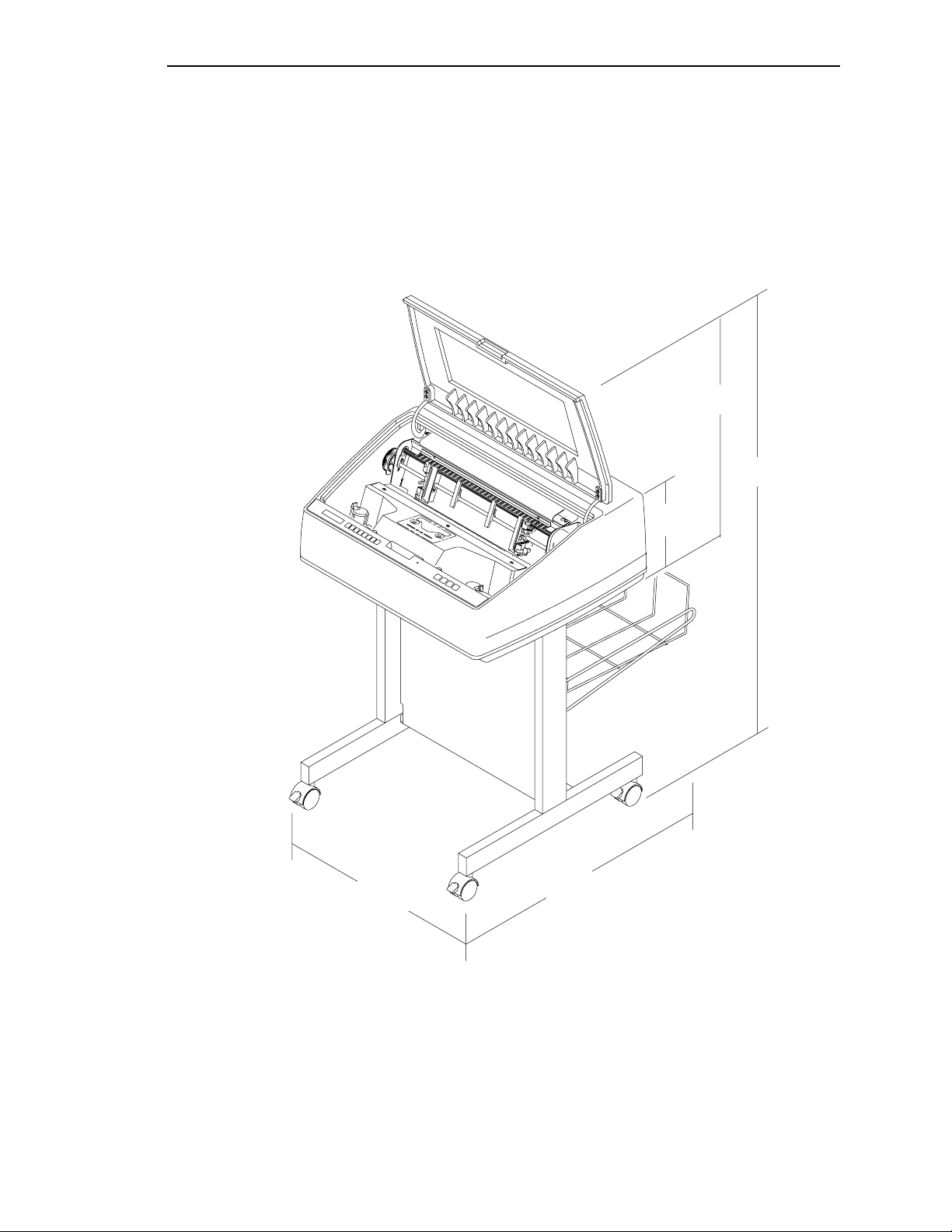
Section 1: Selecting a Site
1
Cabinet Model
Pedestal Model
10
Page 11
Section 1: Selecting a Site
Perform all the procedures in this set of instructions in the order presented for your printer model.
Note
Select a site that meets the following requirements:
Your printer purchase may include installation by a trained service representative.
If installation was included, contact your service representative.
If you are unsure whether installation was included, contact your sales
representative.
• Permits complete opening of the printer cover, and both doors, as appropriate for your model.
• Has a power outlet that supplies 100 to 120 Volts AC + 10%; 50 or 60 Hz or 200 to 240 Volts
10%; 50 or 60 Hz. The printer automatically senses and adjusts itself to conform to the
AC +
correct voltage range.
• Hewlett-Packard recommends that the printer be powered from a separate, dedicated AC
branch circuit. See power specifications.
Note
All electrical work must conform to local electrical codes, which take precedence
over HP specifications.
• Is relatively dust-free.
• Has a temperature range of 10° C to 40° C (50° F to 104° F), and relative humidity from 15%
to 80% non-condensing.
• Is located within the maximum allowable distance to the host computer. This distance
depends on the type of interface you use. Refer to the table at the end of this section.
• Allows at least 27 inches of clearance behind the printer. This permits air to circulate freely
around the printer and provides access to the paper stacking area.
11
Page 12
English
Cabinet Model
27 in.
(68.8 cm)
MINIMUM SPACE REQUIREMENTS
(146.1 cm)
41.0 in.
(104.1 cm)
57.5 in.
83.0 in.
(210.8 cm)
Cabinet Model
with Power Paper Stacker
27.0 in
(68.6 cm)
32.5 in
(82.6 cm)
86.5 in
(219.7 cm)
29.0 in.
(73.7 cm)
27.0 in.
(68.6 cm)
27.0 in
(68.6 cm)
27.0 in.
(68.6 cm)
27.0 in
(68.6 cm)
41.0 in
(104 cm)
32.0 in
(81.3 cm)
57.5 in
(146.1 cm)
12
Page 13
Section 1: Selecting a Site
Pedestal Model
25.0 in
63.5 cm
48.0 in
121.9 cm
10.5 in
26.7 cm
24.6 in
62.5 cm
30 in
76.2 cm
13
Page 14
English
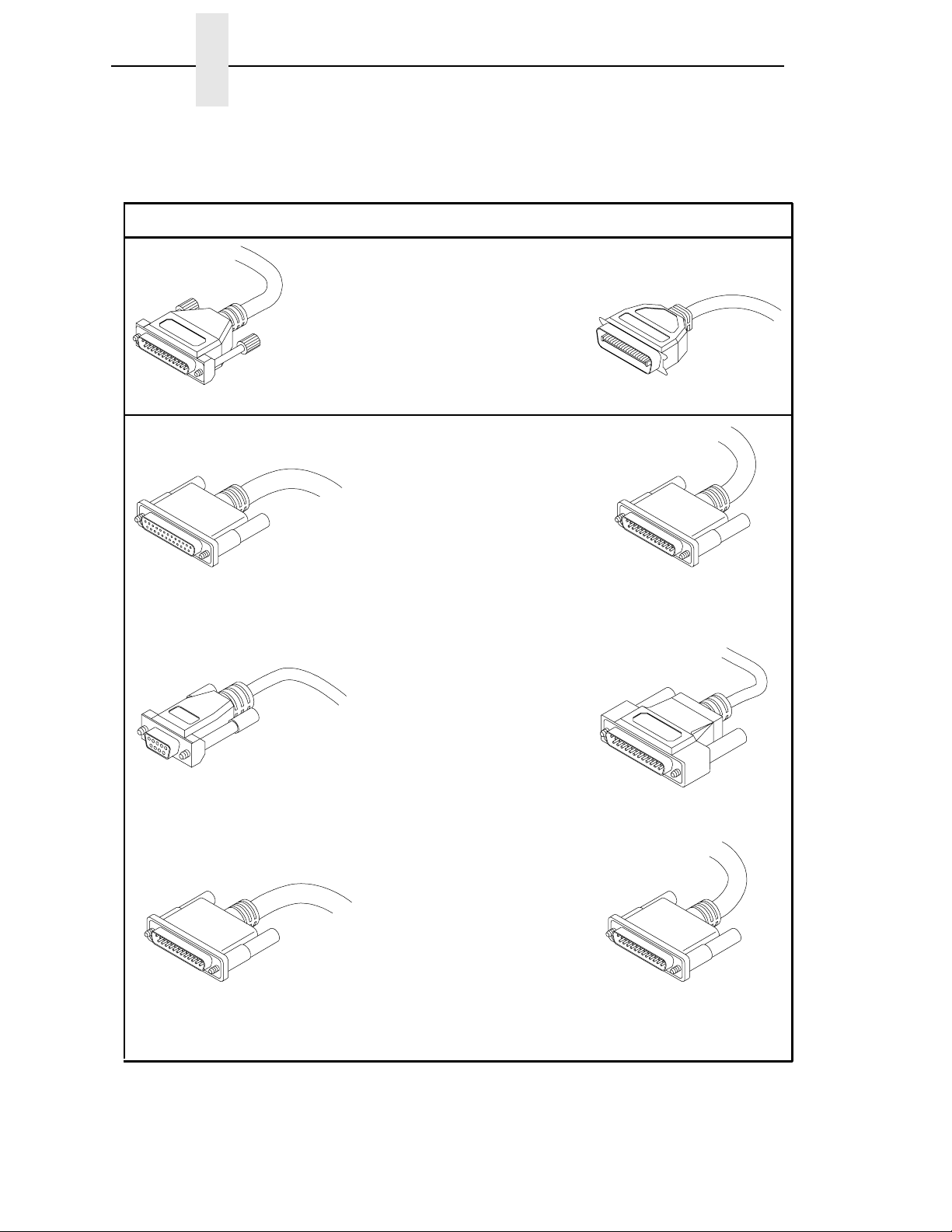
TYPES OF INTERFACES
Computer End
Maximum Length of Cable Printer End
Parallel: 6 feet (2 m)
25 Pin Male 36 Pin Male
RS232: 50 feet (15 m)
RS422: 4000 feet (1220 m)*
25 Pin
25 Pin Male
Female
RS232: 50 feet (15 m)
RS422: 4000 feet (1220 m)*
9 Pin
Female
RS232: 50 feet (15 m)
RS422: 4000 feet (1220 m)*
25 Pin Male
*A copper conductor, twisted-pair telephone cable with a shunt capacitance of 16 pF/foot (52.5 pF/meter)
terminated in a 100 ohm resistive load must be used.
14
25 Pin Male
25 Pin Male
Page 15
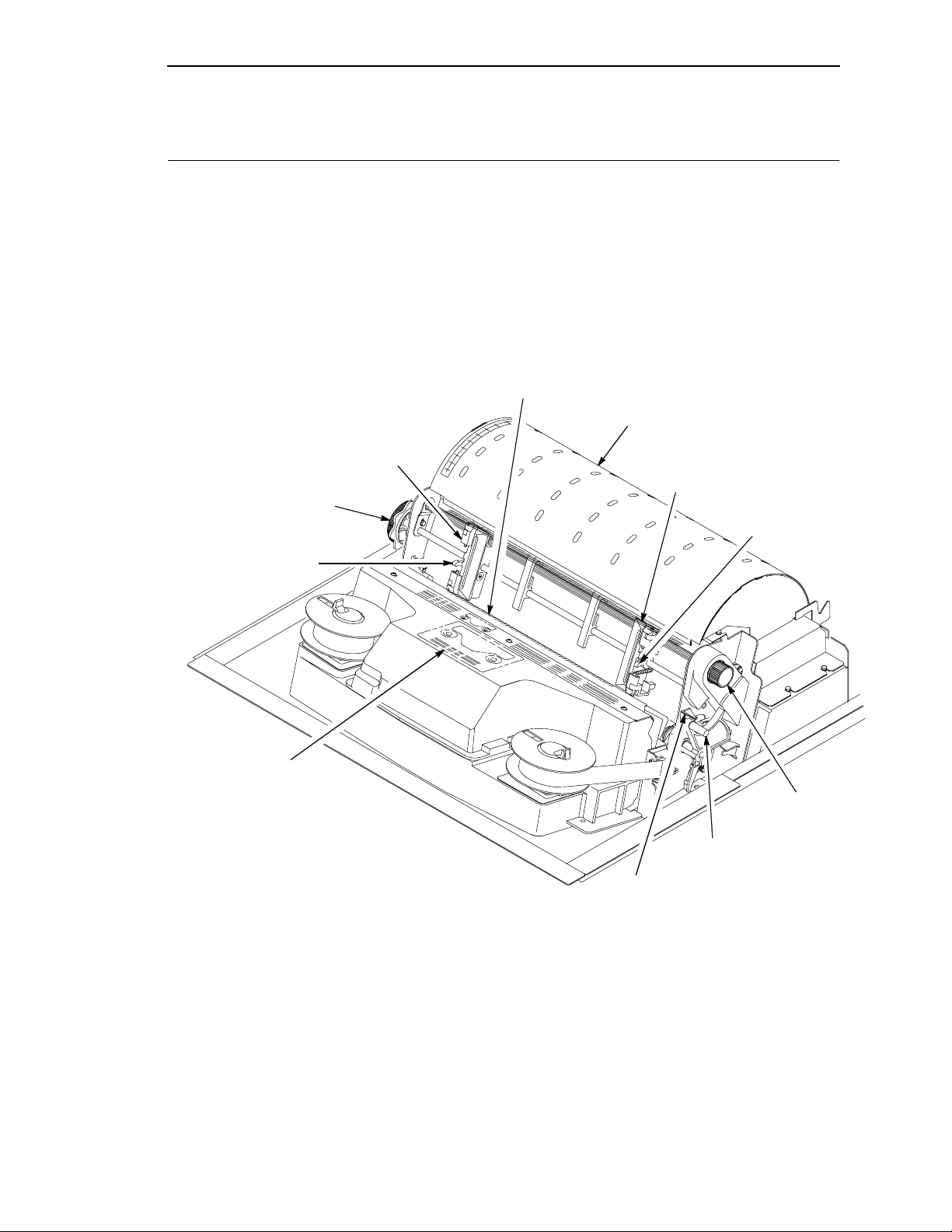
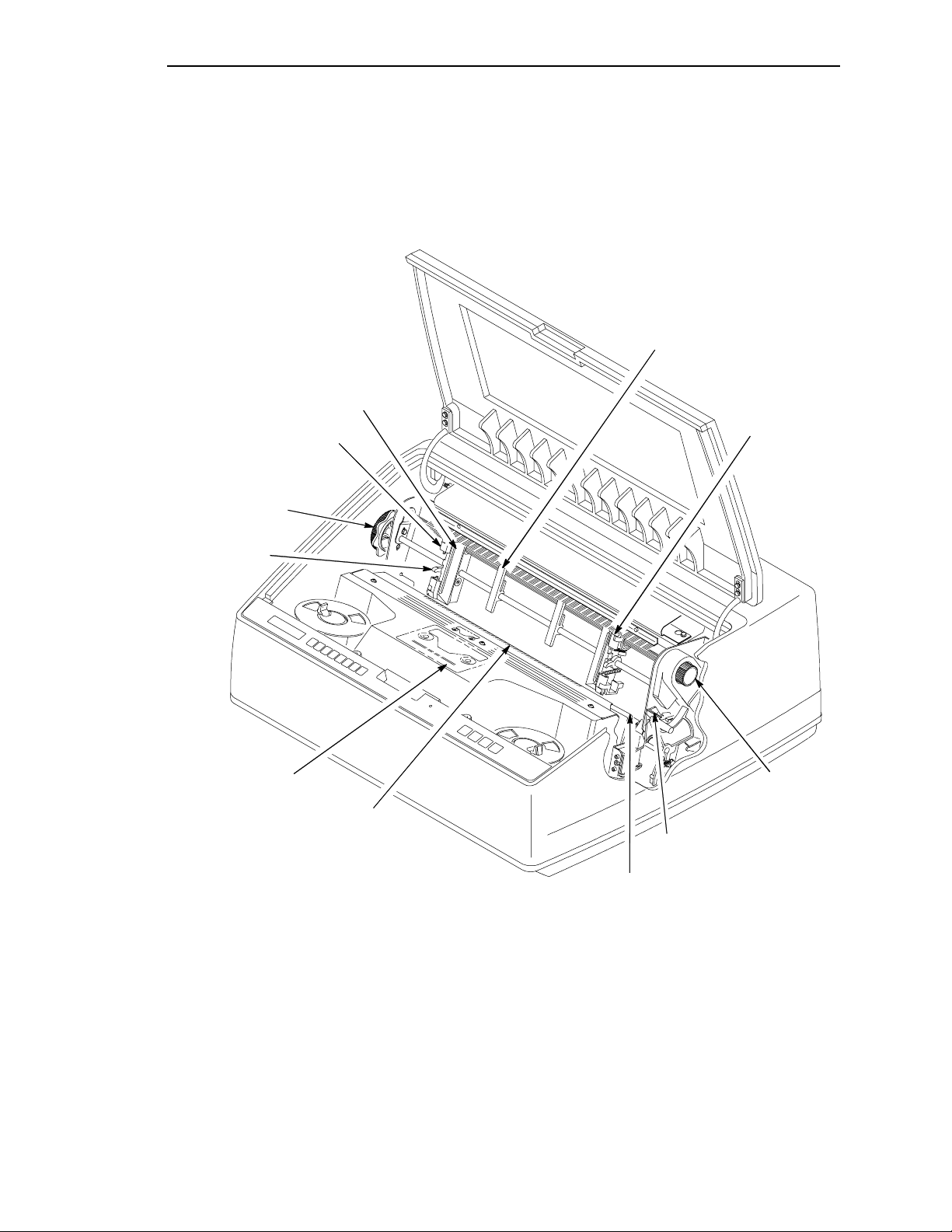
Section 2: Location of Printer Components
Section 2: Location of Printer Components
Familiarize yourself with the names and
locations of the printer components shown in
this section
before
continuing with the rest of
the installation procedure.
CABINET MODEL COMPONENTS
Left Tractor
Horizontal
Adjustment
Knob
Tractor Lock
The procedure to install the ribbon is described
in Section 7 (page 52) of these
Installation
Instructions.
Paper Scale
Lower Paper Guide
Right Tractor
Tractor Lock
Ribbon Loading Path
Diagram
Vertical Position
Knob
Forms Thickness
Lever
Forms Thickness
Pointer
15
Page 16
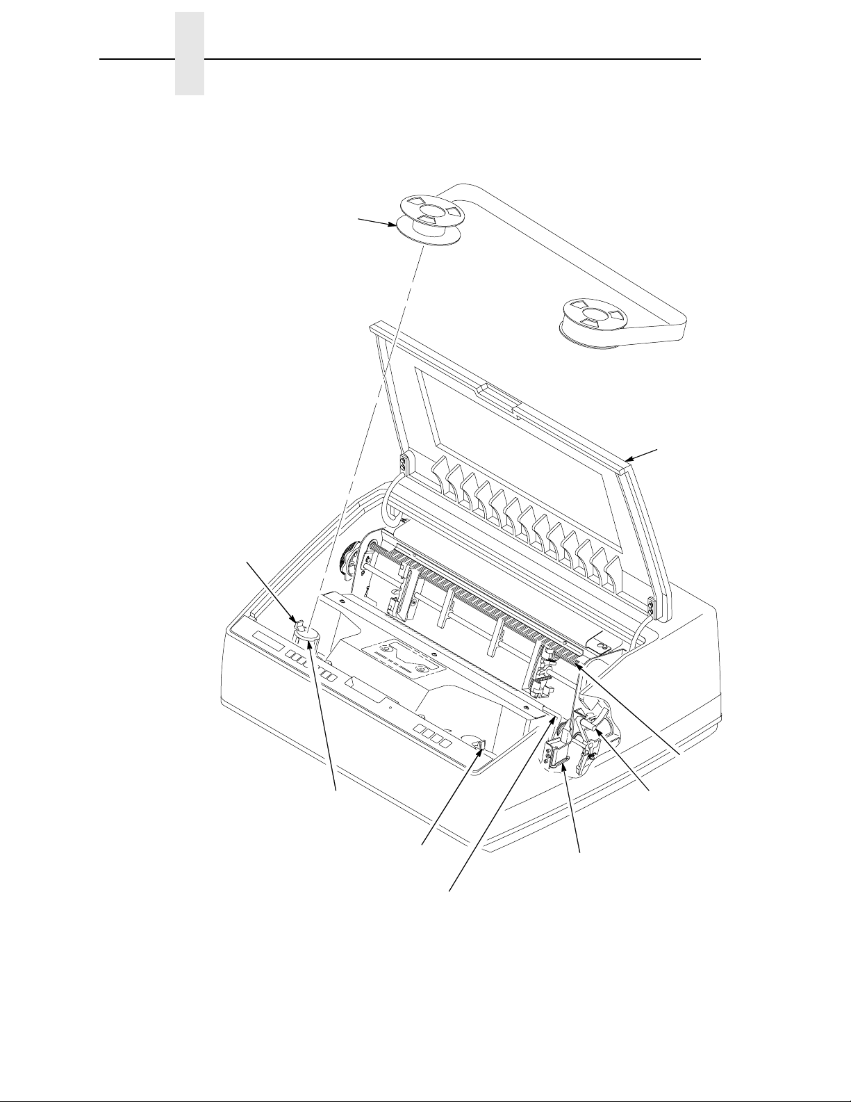
English
Ribbon Spool
CABINET MODEL COMPONENTS
Splined
Shaft
Platen
(hidden)
Base
Casting
Shuttle Cover
Assembly
Paper Support
Ribbon
Guide (2)
16
Ribbon
Mask
Hammer
Bank Cover
Page 17
Tractor Door
Section 2: Location of Printer Components
PEDESTAL MODEL COMPONENTS
Paper Support
Horizontal
Adjustment
Knob
Tractor Lock
Ribbon
Loading Path
Diagram
Left Tractor
Paper Scale
Right Tractor
Vertical Position
Knob
Forms Thickness
Pointer
Ribbon Mask
17
Page 18
English
PEDESTAL MODEL COMPONENTS
Ribbon Spool
Locking Latch
Ribbon Hub
Printer Cover
Splined
Shaft
Forms
Thickness
Lever
18
Locking Latch
Hammer
Bank Cover
Ribbon Guide (2)
Page 19
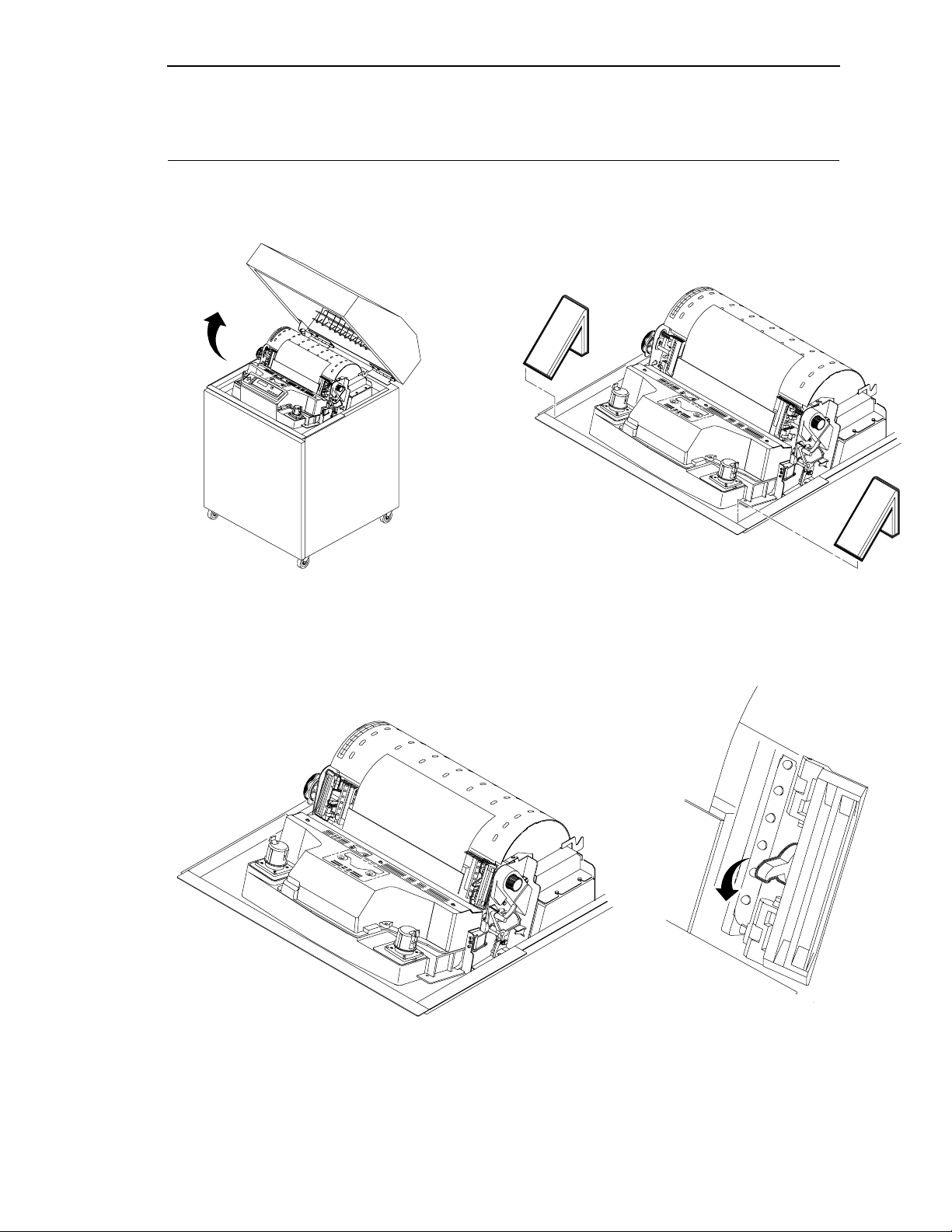
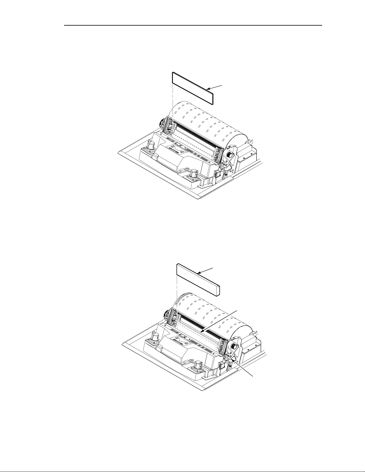
Section 3: Unpacking the Printer
Section 3: Unpacking the Printer
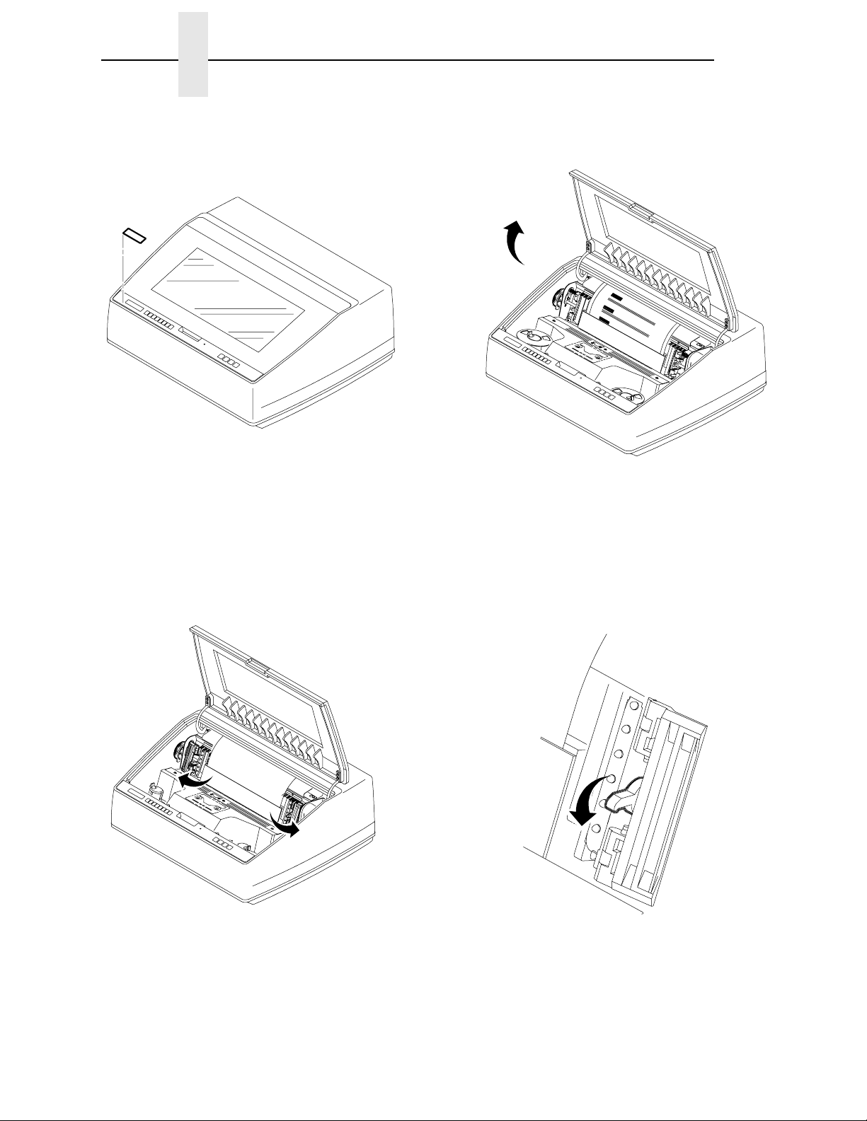
CABINET MODEL
12
Raise the printer cover. Remove the cardboard packing.
34
Open the tractor doors. Push the tractor locks down.
19
Page 20
English
5
The lever is all the way UP
for the fully opened position.
The lever is all the way
DOWN for the closed
position.
Forms Thickness
Lever
Make sure the forms thickness lever is in the
fully opened position (lever is all the way up).
6
The forms thickness lever cannot be moved to
the closed position (lever is down) until the
hammer bank protective foam is removed.
Remove the envelope that contains the sample configuration printout. Store this in the pouch
inside the cabinet for future reference.
20
Page 21
Section 3: Unpacking the Printer
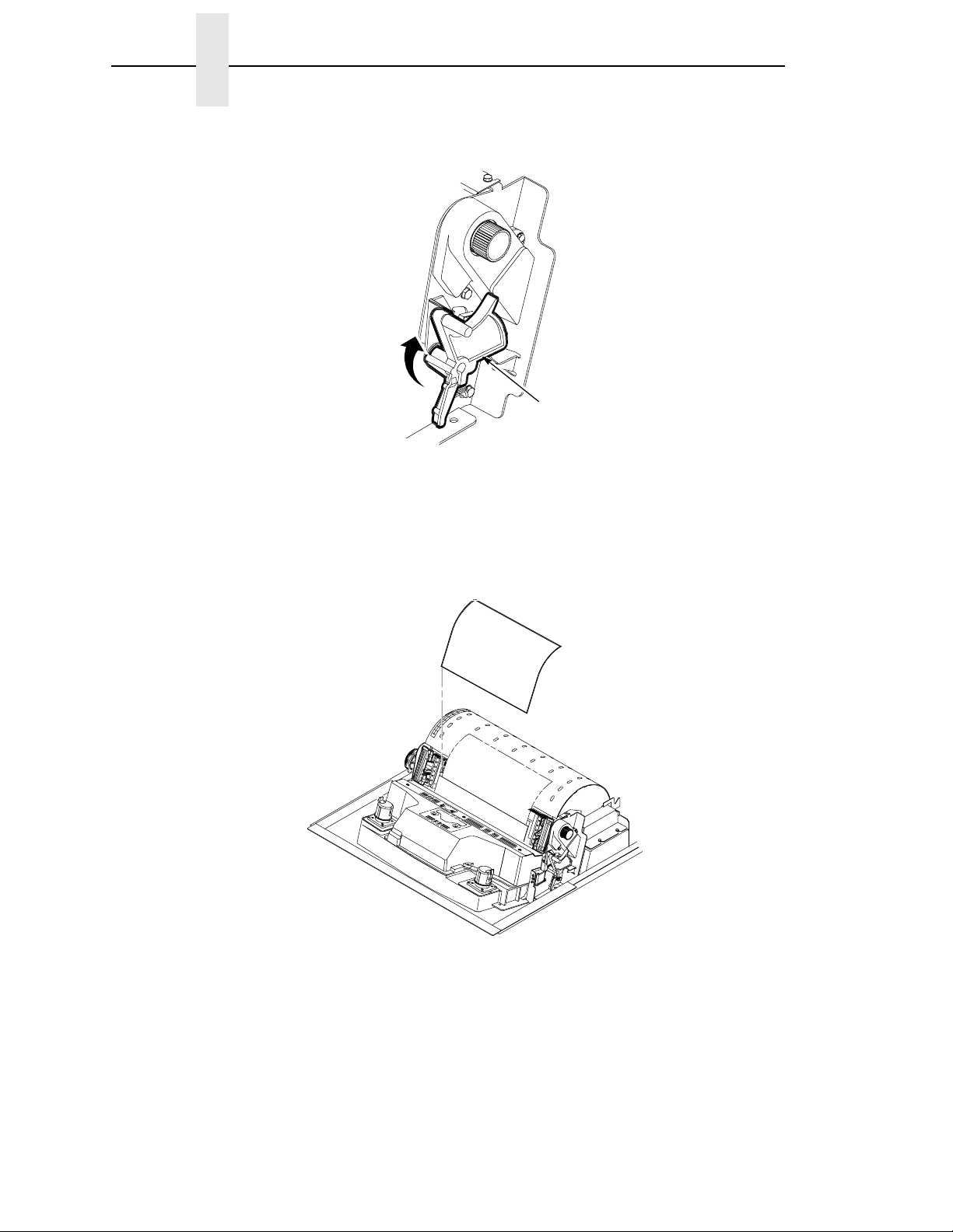
7
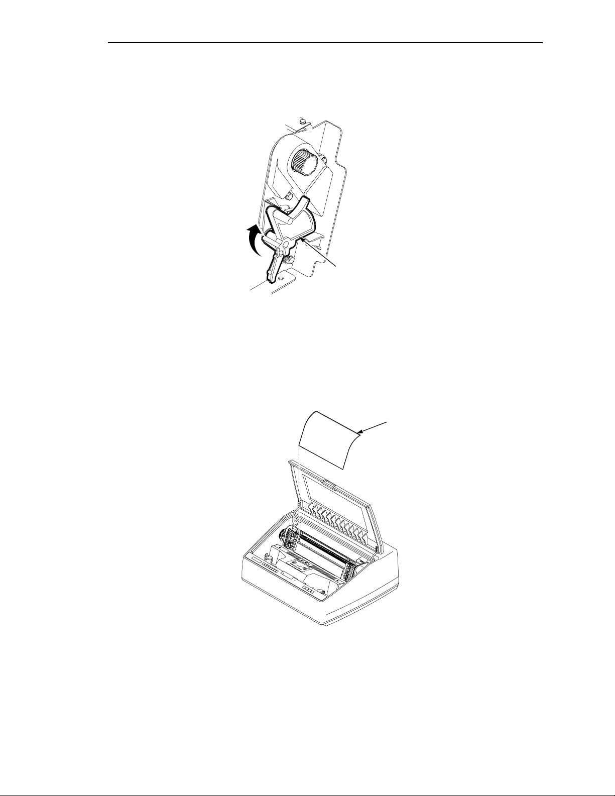
Rotate the hammer bank protective foam toward the front of the printer and remove it from
between the ribbon mask and the platen.
Hammer Bank
Protective Foam
8
Rotate forms thickness lever down to the closed position. Rotate the platen protective foam toward
the front of the printer and out from under the support shaft.
Platen Protective Foam
Support Shaft
Forms Thickness
Lever
21
Page 22
English
9
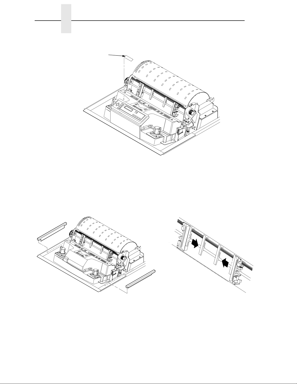
Carefully remove the protective film off liquid crystal display (LCD).
Protective Film
10 11
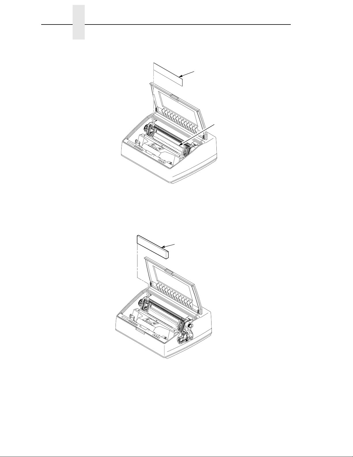
Making sure the tape securing the foam strips
is removed entirely, remove the foam strips.
Slide paper supports inward until they are
approximately four inches from the tractor
door.
22
Page 23
12
Section 3: Unpacking the Printer
Open the cabinet front door and cut the strap that secures the box, which contains the power
cable, printer ribbon, control panel overlay labels, and documentation.
13 14
Open the cabinet rear door. Cut the tie wraps and release the paper chains
from the bags at the top rear of the printer
frame. Remove the tie wraps and plastic bags.
Make sure each chain hangs freely, with no
kinks or knots. Close the cabinet rear door.
23
Page 24
15
English
Tie Wrap
Note
Passive
Tag
Paper
Stacker
If the printer is equipped with a power paper stacker, the paper fence will be
installed. The tie wrap and red tag will need to be removed from the front of the
Tie
Wrap
Tag
printer.
Remove the tie wrap attached to the passive paper stacker or the paper fence. It is marked with a
large, red tag.
Close the cabinet front and rear doors.
Note
If the printer is equipped with a power paper stacker, continue with step 16. If the
stacker is not installed, unpacking is complete.
Fence
24
Page 25
16
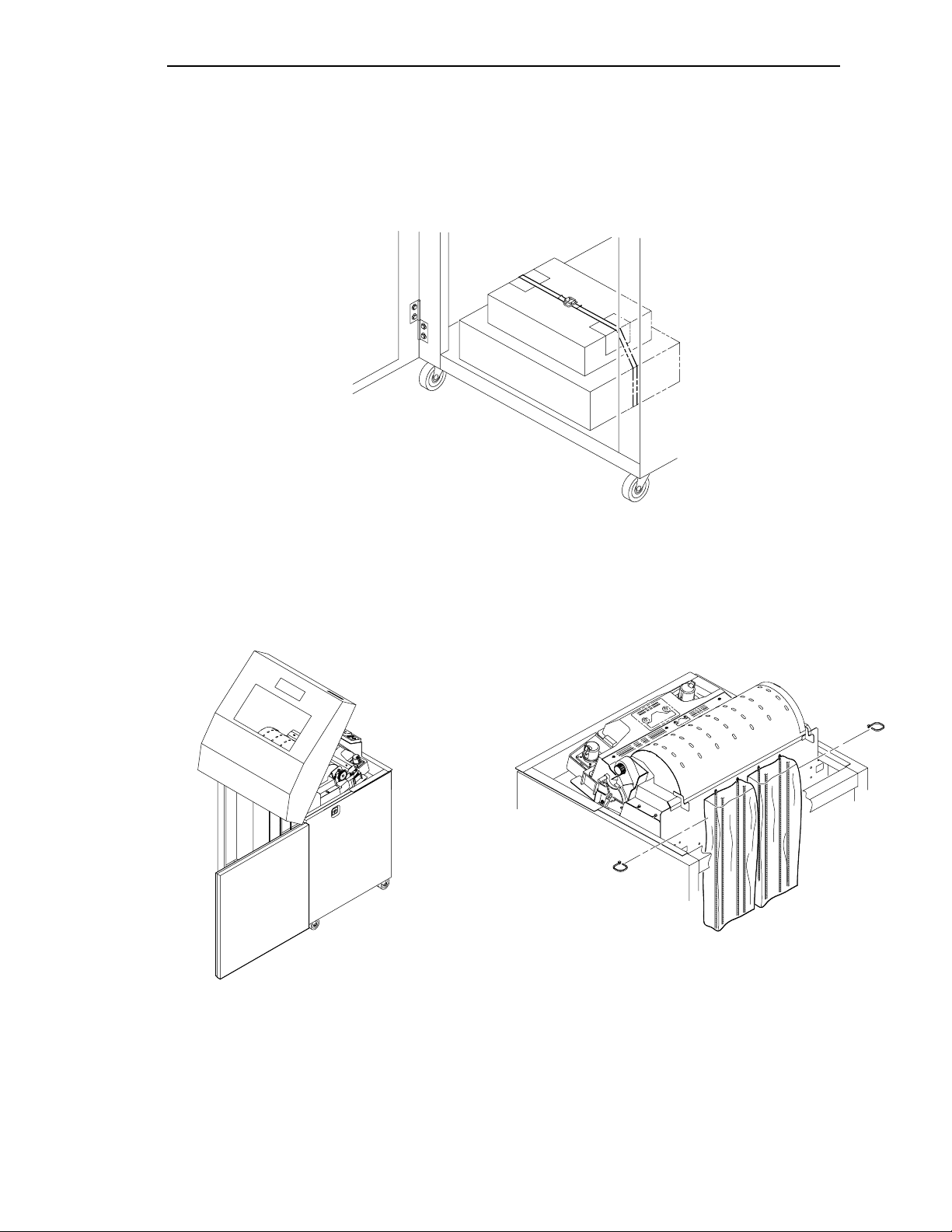
Section 3: Unpacking the Printer
Tie Wrap
Bubble Wrap
Tie Wrap
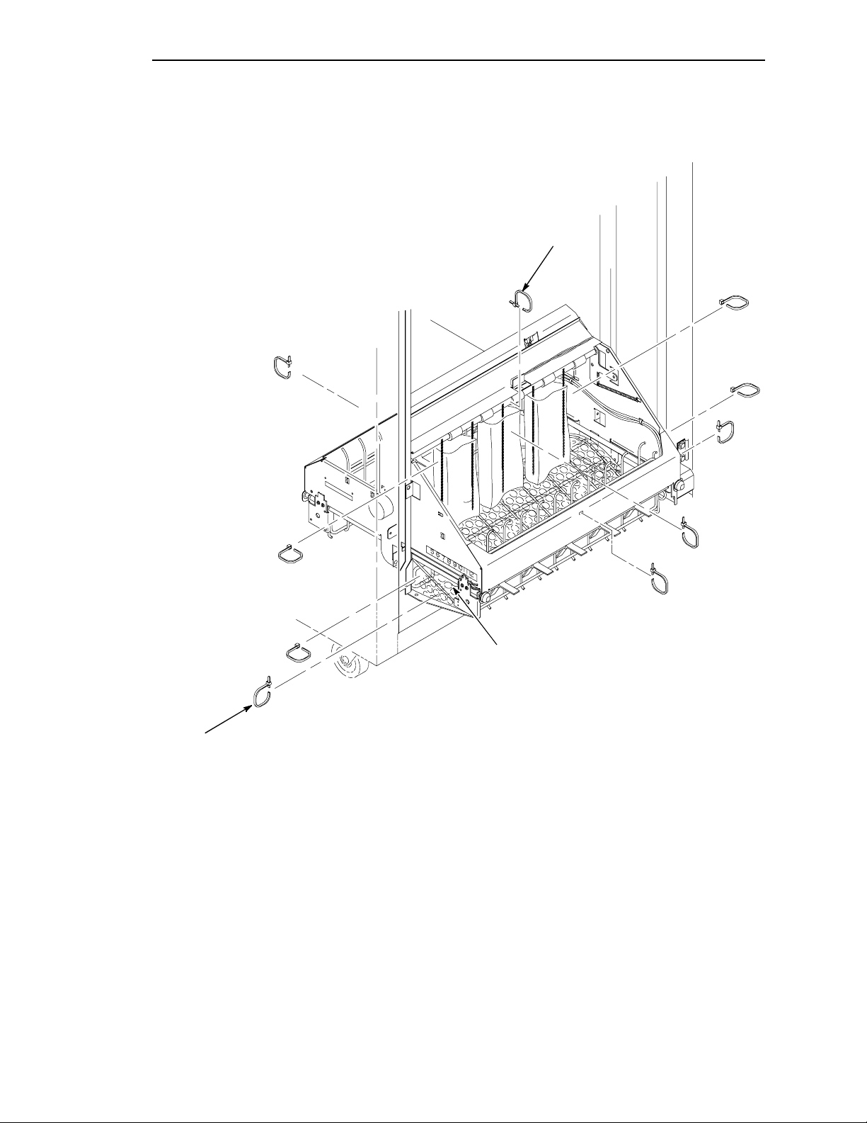
Remove tie wraps. There is one on each side holding the paper guide to the base.
Raise the paper guide to its highest position by hand.
Remove box restraint .
Make sure the static chains hang freely.
25
Page 26
English
PEDEST AL MODEL
12
Remove the film from the LCD. Raise the printer cover.
34
Open the tractor doors. Push the tractor locks down.
26
Page 27
5
Section 3: Unpacking the Printer
The lever is all the way UP
for the fully opened
position.
The lever is all the way
DOWN for the closed
position.
Forms Thickness
Lever
Make sure the forms thickness lever is in the
fully opened position (lever is all the way up).
6
The forms thickness lever cannot be moved to
the closed position (lever is down) until the
hammer bank protective foam is removed.
Envelope
Remove the envelope that contains the sample configuration printout. Store this in your
Printers: User’s Guide
.
LineJet
27
Page 28
English
7
Lift the hammer bank protective foam and remove it from between the ribbon mask and the platen.
Hammer Bank Protective Foam
Support Shaft
8
Rotate forms thickness lever down to the closed position. Rotate the platen protective foam toward
the front of the printer and out from under the support shaft.
Platen
Protective Foam
28
Page 29
Section 3: Unpacking the Printer
910
Clamp
Tag
Slide paper supports inward until they are
approximately four inches from the tractor
door. Close the printer cover.
11
12
$
Remove the tie wrap attached to the wireform
paper path. It is marked with a large, red tag.
$
Fast-On Flag
Ground Wire
Ground Tab
Screw
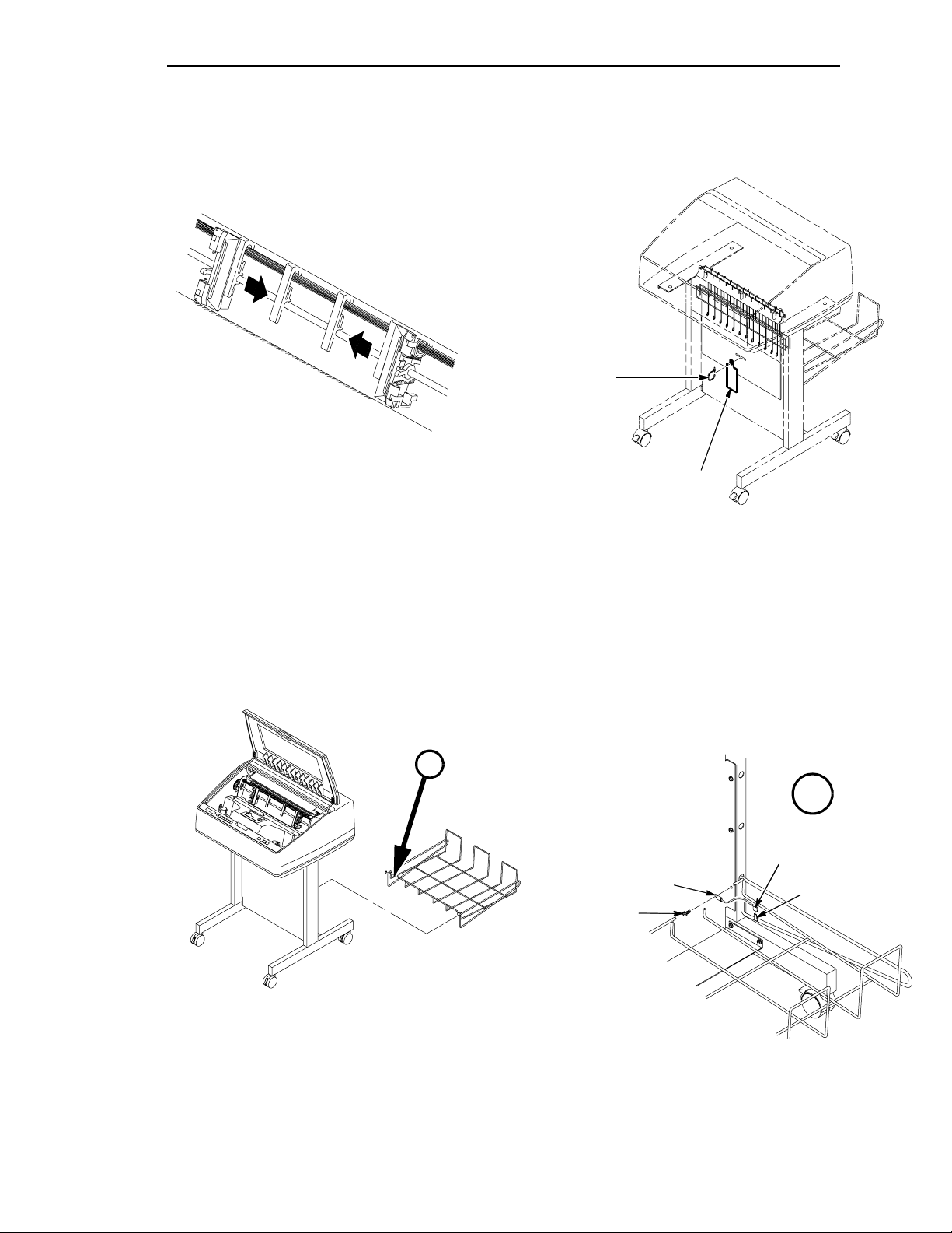
Place the output basket in the holes on the back of the printer. Screw the ground wire attached to
the output basket to the printer pedestal.
29
Page 30
English
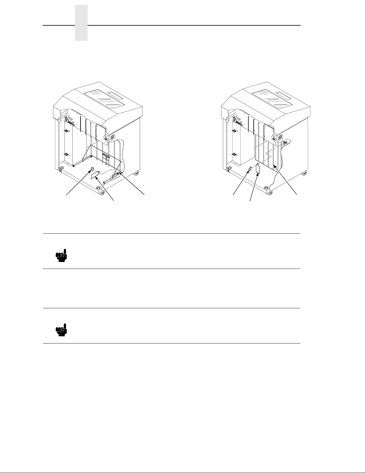
Section 4: Connecting the Cables
CABINET CABLES
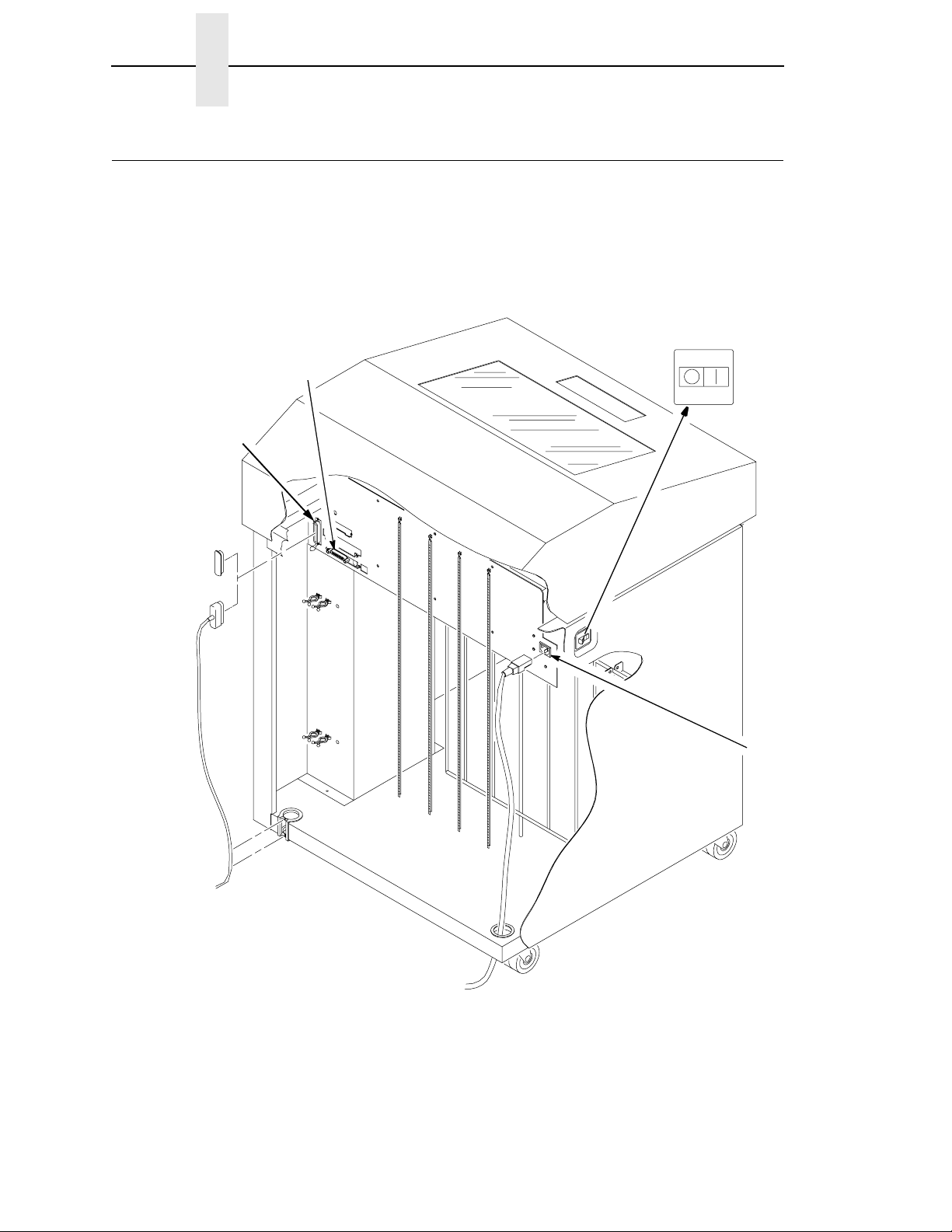
1
Parallel Connector
Serial
Power Switch
Connector
Power Cord
Receptacle
30
Page 31

Section 4: Connecting the Cables
2 3
Description
Label
Check the product description label inside the
rear of the cabinet to verify that the voltage
source at the printer site conforms to the
requirements specified on page 11.
Make sure the printer power switch is set to
OFF.
31
Page 32

English
45
Parallel Connector
Serial Connector
I/O Connector Cover
Connect the (customer-supplied) interface
cable from the host computer to the
appropriate printer interface connector. Refer
to Chapter 4, “Interfaces”, in the
Printers: User’s Guide
connectors and their pin assignments.
Note
Use of shielded cables is
required to comply with
government RFI regulations.
for descriptions of the
LineJet
Rubber
Grommet
Connect the I/O connector to the printer
connector. Secure the connector with the two
wire connector clips (Centronics). Route the
cable down and into the plastic cable
standoffs.
Push the I/O cable into the rubber grommet at
the lower left rear of the cabinet.
Open the cabinet rear door, and remove the
cover from the I/O connector you have
selected.
32
Page 33

Section 4: Connecting the Cables
6 7
If multiple power cords are included in your
shipment, choose the correct one for your
outlet type and discard any others.
Guide the power cable connector up through
the hole in the lower right back corner of the
cabinet. Thread the power cable inside the
bracket and connect as shown.
33
Page 34

English
PEDEST AL CABLES
1
Parallel Connector
Serial Connector
Power Switch
34
Page 35

Section 4: Connecting the Cables
2 3
Label
Check the product description label to verify
that the voltage source at the printer site
conforms to the requirements specified on
page 11.
Make sure the printer power switch is set to
OFF.
35
Page 36

English
Note
4 5
I/O Connection
Cover
Remove the covers from the I/O connector you
have selected.
Connect the (customer-supplied) interface
cable from the host computer to the
appropriate printer interface connector. Secure
the Centronics connector with the two wire
connector clips. Refer to Chapter 4,
“Interfaces,” in the
descriptions of the connectors and their pin
assignments.
User’s Guide
Use of shielded cables is
required to comply with
government RFI regulations.
for
36
Page 37

6
Section 4: Connecting the Cables
Power Cord
AC Power Connector
If multiple power cords are included in your shipment, choose the correct one for your outlet type
and discard any others.
Plug the power cord into the printer AC power connector, then into the AC power outlet.
37
Page 38

English
Section 5: Loading the Paper
CABINET MODEL
12
Open the printer top cover. Raise the forms thickness lever as far as it will
go to the fully opened position.
Note
If the optional power paper
stacker is installed, do all steps
for loading paper. If no power
paper stacker is installed, do
steps 1 through 11 and 15
through 17.
38
Page 39

Section 5: Loading the Paper
34
EDGE
OF
PAPER
BOX
Open both tractor doors.
Open the front door.
Align the paper supply with the label on the
floor. Ensure that the paper pulls freely from
the box.
56
Ribbon Mask
Paper Slot
Feed the paper up through the paper slot
inside the cabinet. Hold the paper in place with
one hand (to prevent it from slipping down
through the paper slot) while pulling it through
from above with your other hand.
Pull the paper above and behind the ribbon
mask, which is a silver metal strip with a clear
plastic edge protector. (Refer to the ribbon
path diagram on the shuttle cover.)
39
Page 40

English
78
Horizontal
Adjustment
Knob
Load the paper on the left tractor sprockets
and close the tractor door.
For a new installation, the left tractor will not be
in position and must be aligned with the first
column. (See the
User’s Guide
for details.)
Unlock the right tractor.
Load the paper onto the sprockets and close
the tractor door. Make sure the leading edge of
the first sheet of paper is perfectly parallel to
the tractor splined shaft (paper is not crooked).
If paper is crooked, reload it onto the tractor
sprockets until its edge is parallel to the splined
shaft.
Slide the right tractor to remove paper slack or
to adjust for various paper widths. Lock the
tractor.
After both tractors are locked, use the
horizontal adjustment knob to make fine
horizontal paper adjustments. These
adjustments are explained in the next step.
40
Page 41

Section 5: Loading the Paper
910
Horizontal Adjustment
Knob
Set the printer power switch to | (on). The
printer initializes. This takes approximately 20
seconds.
Caution
To avoid damage to the printer
caused by printing on the
platen, always position the
inner edge of the closed left
tractor door directly to the left
of the number “1” on the paper
scale.
Align the paper according to the paper scale
on the shuttle cover by turning the horizontal
adjustment knob until the left inner edge of the
closed left tractor door is directly to the left of
the number “1” on the paper scale. Horizontal
adjustment moves both tractors left or right.
(You can also use the paper scale to count
columns.)
41
Page 42

English
11 12
Lower the forms thickness lever. Using the rear control panel, press the
STACKER UP button and wait for the paper
guide to reach the top of its travel.
13 14
Using the rear control panel, press the PAPER
ADVANCE key and hand feed the paper until
paper reaches the wire tent and there is an
excess of 3-5 pages. Be certain the paper
passes through the paper stacker throat.
Stack the 3-5 sheets of paper on top of the
wire paper tent, making sure the paper lies
with the natural folds.
42
Page 43

15 16
OFFLINE
Config. Control
Section 5: Loading the Paper
The printer displays “OFFLINE”.
If a message other than “OFFLINE” displays,
refer to Chapter 5, “Routine Service and
Diagnostics” in the
User’s Guide
.
17
Press the FF (Form Feed) key five times.
Make sure the paper feeds properly beyond
the tractors and over the lower paper guide.
Open the rear door. Feed enough paper to
ensure that the paper stacks correctly.
Press the ON LINE key on the control panel or
the rear control panel. “ONLINE” displays on
the LCD.
The stacker frame returns to its proper position
for printing.
Close the cabinet front and rear doors.
Continue on to the next section to set the top-
of-form.
43
Page 44

English
PEDEST AL MODEL
12
Forms Thickness
Lever
Open the printer top cover. Raise the forms thickness lever as far as it will
go (fully opened position).
3
Swing open both tractor doors.
44
Page 45

Section 5: Loading the Paper
45
Ribbon Mask
Paper Slot is 8 inches
below printer base
Feed the paper up through the paper slot. Hold
the paper in place with one hand (to prevent it
from slipping down through the paper slot)
while pulling it through from above with your
other hand.
Pull the paper above and behind the ribbon
mask, which is a silver metal strip with a clear
plastic edge protector. (Refer to the ribbon
path diagram on the shuttle cover.)
45
Page 46

English
67
Horizontal
Adjustment
Knob
Load the paper on the left tractor sprockets
and close the tractor door.
For a new installation, the left tractor will not be
in position and must be aligned with the first
column. (See the
User’s Guide
for details.)
Unlock the right tractor.
Load the paper onto the sprockets and close
the tractor door. Make sure the leading edge of
the first sheet of paper is perfectly parallel to
the tractor splined shaft (paper is not crooked).
If paper is crooked, reload it onto the tractor
sprockets until its edge is parallel to the splined
shaft.
Slide the right tractor to remove paper slack or
to adjust for various paper widths. Then, lock
the tractor.
After both tractors are locked, use the
horizontal adjustment knob to make fine
horizontal paper adjustments. These
adjustments are explained in the next step.
46
Page 47

Section 5: Loading the Paper
89
Horizontal Adjustment
Knob
Caution
Align the paper according to the paper scale
on the shuttle cover by turning the horizontal
adjustment knob until the left inner edge of the
closed left tractor door is directly to the left of
the number “1” on the paper scale. Horizontal
adjustment moves both tractors left or right.
(You can also use the paper scale to count
columns.)
To avoid damage to the printer
caused by printing on the
platen, always position the
inner edge of the closed left
tractor door directly to the left
of the number “1” on the paper
scale.
Set the printer power switch to | (on). The
printer initializes, which takes approximately 20
seconds.
47
Page 48

English
Note
10 11
OFFLINE
Config. Control
Lower the forms thickness lever. The printer displays “OFFLINE”.
If a message other than “OFFLINE” displays,
refer to Chapter 5, “Routine Service and
Diagnostics” in the
User’s Guide.
If English will be your display
primary language, disc ar d
foreign language overlays at
this point.
12
Press the ON LINE key on the control panel. “ONLINE” displays on the LCD.
The printer can be put offline by pressing the ON LINE key a second time. This key toggles the
printer online and offline.
48
Page 49

13 14
Lower Paper
Guide
Section 5: Loading the Paper
Guide the paper over the lower paper guide
and through the slot in the top cover.
Press the FF (Form Feed) key four times.
Make sure the paper feeds properly beyond
the tractors and over the lower paper guide.
Feed enough paper to ensure that the paper
stacks correctly.
Continue on to the next section to set the top-
of-form.
49
Page 50

English
Section 6: Setting the T op-of-Form
12
Vertical Position
Knob
TOF Indicator
Paper
Perforation
First Print Line
Verify the printer is offline and the printer cover
is open.
Raise the forms thickness lever as far as it will
go. “CLOSE PLATEN” displays.
Turn the vertical position knob to align the top
of the first print line with the TOF indicator.
The first print line on the form should be 1/2
inch or more from the perforation for best print
quality.
50
Page 51

3
Section 6: Setting the Top-of-Form
Thin (1 part)
Medium (3 parts)
Thick (6 parts)
Lower the forms thickness lever. Set it to match the paper thickness. See scale above.
Note
Do not set the forms thickness lever too tightly; too much friction can cause paper
jams, ribbon jams, smeared ink, or wavy print. The A-B-C scale corresponds
approximately to 1-, 3-, and 6-part paper thickness of 20 lb paper. Adjust until you
have the desired print quality.
A
B
C
4
Cabinet Model
Pedestal Model
Press the SET TOF key on the control panel. The paper moves down to the print position and
aligns to the top-of-form.
Note
The forms thickness lever must be closed; otherwise there will be no paper
movement when you press SET TOF.
51
Page 52

English
Section 7: Installing the Ribbon
12
Refer to the ribbon path diagram molded onto
the shuttle cover.
Note
Placing the printer online
without a ribbon installed will
result in loss of data.
Verify that the printer is offline and the printer
cover is open.
52
Page 53

Section 7: Installing the Ribbon
34
Hub
Latch
Raise the forms thickness lever as far as it will
go. “CLOSE PLATEN” displays.
Note
Printer includes a box of six 60yard bar code/OCR ribbons.
Use only the ribbons listed
below:
C3207A Box of 6, 60-yard
text ribbons
C3208A Box of 6, 100-yard
text ribbons
C3209A Box of 6, 60-yard bar
code/OCR ribbons
C3210A Box of 6, 100-yard
bar code/OCR
ribbons
Squeeze the right hub latch and place the full
spool on the right hub. Press the spool down
until the hub latch snaps into place. (Make sure
the ribbon is to the outside of the spool).
53
Page 54

5
English
Hammer Bank Cover
Ribbon Mask
Ribbon Guide
Paper
Ribbon Mask
Hammer Bank Cover
Platen
Ribbon
Hammer
Tip
Thread the ribbon around the ribbon guide and along the ribbon path. (Refer to the ribbon path
diagram on the shuttle cover.) Be sure to thread the ribbon between the hammer bank cover and
the ribbon mask.
54
Page 55

6
Section 7: Installing the Ribbon
Cabinet Model Shown
Caution
The ribbon must not be
twisted. A twisted ribbon can
lower print quality, shorten
ribbon life, or cause paper
jams.
7
Thin (1 part)
Medium (3 parts)
Thick (6 parts)
Squeeze the left hub latch and place the empty
spool on the left hub. Press the spool down
until the hub latch snaps into place. Turn the
empty spool by hand to make sure the ribbon
tracks correctly in the path and around the
ribbon guides.
A
B
C
Lower the forms thickness lever. Set it to match the paper thickness.
Note
Do not set the forms thickness lever too tightly; too much friction can cause paper
jams, ribbon jams, smeared ink, or wavy print. The A-B-C scale corresponds
approximately to 1-, 3-, and 6-part paper thickness of 20 lb paper. Adjust until you
have the desired print quality.
55
Page 56

English
ON LINE
+
UNTIL
UNTIL
OR
ENTER
UNTIL
UNTIL
ENTER
Section 8: Testing the Printer
Step Key Result Notes
1. Make sure that the printer top cover is open and the forms thickness lever is lowered.
2. The printer must be offline for
3. Allows you to make configuration
4.
5.
6.
7.
8. Cycle through the choices.
OFFLINE
CONFIG. CONTROL
ENTER SWITCH
UNLOCKED
OFFLINE
CONFIG. CONTROL
OFFLINE
DIAGNOSTICS
DIAGNOSTICS
Printer Tests
DIAGNOSTICS
Test Width
Test Width
Full Width*
Test Width
X
testing.
changes.
X = Full Width or 80 columns.
9. To select paper size.
10.
11.
12.
13. Starts the test.
Test Width
X*
DIAGNOSTICS
Test Width
DIAGNOSTICS
Printer Tests
Printer Tests
Shift Recycle*
Printer Tests
Shift Recycle*
56
Page 57

Section 8: Testing the Printer
ENTER
+
CLEAR
Step Key Result Notes
14. Stops the test.
15. Locks the ENTER key.
16.
Printer Tests
Shift Recycle*
ENTER SWITCH
LOCKED
OFFLINE
CONFIG. CONTROL
17. Examine the print quality. The characters should be fully formed and of uniform
density. If the test does not run or characters appear malformed, check the forms
thickness lever. It should be set to the form in use (A = single-part; B = three-part; C =
six-part). Check the ribbon. It should not be twisted, and it should be tracking correctly.
If there is nothing wrong with the forms thickness lever or the ribbon, contact your
Hewlett-Packard Customer Service Engineer.
18. If the print quality is good, close the printer cover; set the top-of-form, then press
ON LINE to enable printing. To select an emulation and configure the printer with the
control panel, refer to the
LineJet Ser ies Printers: User’s Guide
.
57
Page 58

English
Congratulations!
You have successfully installed of your new HP LineJet printer.
To ensure continuous availability of your printer, you may want to order additional ribbons at this
time:
Ribbons for LineJet printers can be ordered in the U.S.A. by calling Hewlett-Packard at
1-800-538-8787. Customers outside the U.S.A. should contact their local Hewlett-Packard sales
and support office for ordering information.
Refer now to the
to familiarize yourself with its operation.
Other manuals included in this shipment:
•
LineJet Printers: Quick Reference Guide
perform the day-to-day printer operations and describes the functions of the control panel
keys.
•
LineJet Printers: PCL®-II/LinePrinter Plus® Technical Reference Manual
This book is for programmers who are using HP’s Printer Control Language (PCL) II to access
LineJet printer features.
LineJet Printers: User’s Guide
(p/n 171252-001PX) to configure your printer and
(p/n 171248-001PX). This book explains how to
(p/n 171249-001PX).
58
Page 59

Stampanti LineJet™
Modello cabinet e a piedistallo
Instruzioni d’installazione
Page 60

Page 61

Introduzione
A
Introduzione
Queste
tedesco e spagnolo). Scegliere la lingua desiderata e continuare. Questo documento descrive
l’installazione delle stampanti modello cabinet e a piedistallo. Le procedure che differiscono per i
modelli cabinet e per quelli a piedistallo vengono descritte in sezioni separate. In certi casi esiste
inoltre una sezione separata per i modelli cabinet con installato il raccoglitore automatico della
carta.
Istruzioni d’installazione
sono costituite de cinque sezioni (inglese, italiano, francese,
Attenzione, Avvertenza, e Nota
ttenzione
Avvertenza
Gli avvisi Attenzione descrivono condizioni che possono mettere in pericolo
l’utente e danneggiare la stampante.
Gli avvisi Avvertenza forniscono informazioni su condizioni che potrebbero
danneggiare la stampante o altre apparecchiature correlate.
Nota
Le note forniscono utili suggerimenti sul funzionamento e la manutenzione della
stampante.
61
Page 62

Italiano
Sezione 1: Scelta del luogo di installazione
1
Modello cabinet
62
Modello a piedistallo
Page 63

Sezione 1: Scelta del luogo di installazione
Seguire tutte le procedure di questo manuale nell’ordine in cui vengono presentate per il modello
di cui si dispone.
Nota
Scegliere un’ubicazione che soddisfi i seguenti requisiti:
Il modello di stampante acquistato potrebbe includere l’installazione da parte di un
tecnico specializzato. Se l'installazione è inclusa, rivolgersi al servizio di
assistenza. Se non si è certi che l'installazione è inclusa, rivolgersi al servizio di
vendita.
• Permetta l’apertura completa del coperchio della stampante e di entrambi gli sportelli, a
seconda del modello.
• Abbia una presa di rete da 100 a 120 Volt c.a. + 10%; 50 o 60 Hz o 200 a 240 Volt c.a. + 10%;
50 or 60 Hz. La stampante rileva automaticamente la corretta tensione e vi si adatta.
• La Hewlett-Packard consiglia di alimentare la stampante da un circuito c.a. separato e
dedicato. Vedere le specifiche di alimentazione.
Nota
Tutti i componenti elettrici devono essere conformi alle normative elettriche locali,
che hanno la priorità sulle specifiche HP.
• Sia per quanto possibile priva di polvere.
• Abbia un'escursione termica compresa tra 10° C e 40° C (tra 50° F e 104° F), con un'umidità
relativa dal 15% all'80% senza condensa.
• Si trovi entro i limiti della massima distanza consentita dal computer host. Questa distanza
dipende dal tipo di interfaccia utilizzata. Consultare la tabella alla fine di questa sezione.
• Vi siano almeno 70 cm di spazio libero dietro la stampante. Questo garantisce una buona
ventilazione intorno alla stampante e permette di accedere alla zona in cui viene raccolta la
carta.
63
Page 64

Italiano
Modello cabinet
27 in.
(68.8 cm)
REQUISITI DI SPAZIO MINIMO
(146.1 cm)
41.0 in.
(104.1 cm)
57.5 in.
(73.7 cm)
83.0 in.
(210.8 cm)
Modello cabinet
con raccoglitore automatico
della carta
27.0 in
(68.6 cm)
32.5 in
(82.6 cm)
86.5 in
(219.7 cm)
29.0 in.
27.0 in.
(68.6 cm)
27.0 in
(68.6 cm)
27.0 in.
(68.6 cm)
27.0 in
(68.6 cm)
41.0 in
(104 cm)
32.0 in
(81.3 cm)
57.5 in
(146.1 cm)
64
Page 65

Sezione 1: Scelta del luogo di installazione
Modello a piedistallo
25.0 in
63.5 cm
48.0 in
121.9 cm
10.5 in
26.7 cm
24.6 in
62.5 cm
30 in
76.2 cm
65
Page 66

Italiano
TIPI DI INTERFACCIA
Lato computer
Lunghezza massima del cavo Lato stampante
Parallela: 2 m
Maschio a 25 pin Maschio a 36 pin
RS232: 15 m
RS422: 1220 m*
Femmina a 25 pin
Maschio a 25 pin
RS232: 15 m
RS422: 1220 m*
Femmina a 9 pin
Maschio a 25 pin
RS232: 15 m
RS422: 1220 m*
Maschio a 25 pin
*Usare un doppino telefonico di rame con capacità in parallelo di 16 pF/piede (52,5 pF/metro),
terminato con un carico resistivo di 100 ohm.
Maschio a 25 pin
66
Page 67

Sezione 2: Ubicazione dei componenti della stampante
Sezione 2: Ubicazione dei componenti della stampante
Prendere familiarità con i nomi e l'ubicazione
dei componenti della stampante indicati in
prima
questa sezione
di proseguire la
procedura di installazione.
COMPONENTI DEL MODELLO CABINET
Sportello del
trascinamoduli di sinistra
Manopola di
regolazione
orizzontale
Blocco del
trascinamoduli
La procedura per installare il nastro è descritta
nella sezione 7 (pagina 104) di queste
Istruzioni di installazione.
Scala della carta
Guida inferiore della carta
Trascinamoduli di destra
Blocco del trascinamoduli
Diagramma del percorso
del nastro
Manopola
posizionamento
verticale
Leva spessore
moduli
Puntatore dello
spessore moduli
67
Page 68

Italiano
Bobina del nastro
COMPONENTI DEL MODELLO CABINET
Albero
scanalato
Rullo
(non
visibile)
Basamento
Mascherina
del nastro
(non visibile)
Unità martelli
(non visibile)
Supporto carta
Trascinamoduli
Leva spessore
moduli
Guida
del nastro (2)
Gruppo coperchio
navetta
68
Page 69

COMPONENTI DEL MODELLO A PIEDISTALLO
Sportello del trascinamoduli
Trascinamoduli di sinistra
Sezione 2: Ubicazione dei componenti della stampante
Supporto carta
Trascinamoduli
di destra
Manopola di
regolazione
orizzontale
Blocco del
trascinamoduli
Diagramma del
percorso di caricamento
del nastro
Scala della carta
Manopola
posizionamento
verticale
Leva spessore
moduli
Puntatore dello
spessore moduli
Mascherina del nastro
69
Page 70

Italiano
Bobina del nastro
COMPONENTI DEL MODELLO A PIEDISTALLO
Coperchio della stampante
Fermo
Perno della bobina di nastro
Fermo
Mascherina
del nastro
Albero
scanalato
Leva spessore
moduli
Guida
del nastro (2)
70
Page 71

Sezione 3: Disimballaggio della stampante
Sezione 3: Disimballaggio della stampante
MODELLO CABINET
12
Sollevare il coperchio della stampante. Rimuovere il cartone di imballaggio.
34
Aprire gli sportelli del trascinamoduli. Abbassare i blocchi del trascinamoduli.
71
Page 72

Italiano
5
La leva è sollevata al
massimo per la posizione
completamente aperta.
La leva è abbassata al
massimo per la posizione
completamente chiusa.
Leva spessore
moduli
Assicurarsi che la leva spessore moduli sia
completamente aperta (sollevata al massimo).
6
La leva spessore moduli non si può spostare in
posizione chiusa (abbassata) finché non si
rimuove il materiale espanso di protezione del
rullo.
Togliere la busta che contiene lo stampato della configurazione tipo. Conservare questo stampato
nella tasca interna del cabinet per futura consultazione.
Rimuovere il materiale espanso di protezione del rullo.
72
Page 73

Sezione 3: Disimballaggio della stampante
7
Ruotare il materiale espanso di protezione dell'unità a martelli verso la parte anteriore della
stampante e toglierlo dalla mascherina del nastro e dal rullo che lo racchiudono.
Materiale espanso a
protezione dei martelli
8
Ruotare il materiale espanso di protezione del rullo verso la parte anteriore della stampante
facendolo passare sotto l'albero di supporto.
Materiale espanso a protezione del rullo
Albero di supporto
73
Page 74

Pellicola protettiva
9
Italiano
Togliere delicatamente la pellicola protettiva dal display LCD a cristalli liquidi.
10 11
Dopo aver rimosso completamente il nastro
che bloccava il materiale espanso, togliere le
strisce di materiale espa nso.
Far scorrere all’interno le guide della carta
finché non vengono a trovarsi a circa 6 cm
dallo sportello del trascinamoduli.
74
Page 75

12
Sezione 3: Disimballaggio della stampante
Aprire lo sportello frontale del cabinet e tagliare il nastro che sigilla la scatola contenente il cavo di
alimentazione, il nastro della stampante, le etichette per il pannello di controllo e la
documentazione.
13 14
Aprire lo sportello posteriore del cabinet. Tagliare le fascette avvolgenti e liberare le
catene della carta dai sacchetti sul retro del
telaio della stampante. Togliere le fascette
avvolgenti e i sacchetti di plastica. Controllare
che ogni catena sia liberamente sospesa
senza formare nodi o gomiti. Chiudere lo
sportello posteriore del cabinet.
75
Page 76

15
Italiano
Fascetta
Nota
Raccoglitore
Etichetta
passivo
Se la stampante dispone di un raccoglitore automatico, avrà installata la griglia per
la carta. Rimuovere la fascetta e l'etichetta rossa dalla parte anteriore della
Anello
Etichetta
stampante.
Rimuovere la fascetta applicata al raccoglitore passivo o alla griglia della carta. Essa è
contrassegnata con una grande etichetta rossa.
Chiudere lo sportello frontale e quello posteriore.
Nota
Se la stampante dispone di un raccoglitore automatico, passare al punto 16. Se il
raccoglitore non è installato, il disimballaggio a questo punto è terminato.
Griglia
76
Page 77

16
Sezione 3: Disimballaggio della stampante
Fascetta
Foglio di plastica a bolle
Fascetta
Rimuovere le fascette. Ne esiste una per lato che fissa la guida della carta alla base.
Sollevare manualmente la guida della carta nella posizione più alta.
Togliere il fermo della scatola.
Assicurarsi che le catene statiche pendano liberamente.
77
Page 78

Italiano
MODELLO A PIEDISTALLO
12
Togliere la pellicola dal display LCD a cristalli
liquidi.
Sollevare il coperchio della stampante.
34
Aprire gli sportelli del trascinam oduli. Abbassare i blocchi del trascinamoduli.
78
Page 79

5
Sezione 3: Disimballaggio della stampante
La leva è sollevata al
massimo per la posizione
completamente aperta.
La leva è abbassata al
massimo per la posizione
completamente chiusa.
Leva spessore
moduli
Assicurarsi che la leva spessore moduli sia
completamente aperta (sollevata al massimo).
6
La leva spessore moduli non si può spostare in
posizione chiusa (abbassata) finché non si
rimuove il materiale espanso di protezione del
rullo.
Busta
Togliere la busta che contiene lo stampato della configurazione tipo. Conservarlo nel manuale
Stampanti LineJet: Manuale utente.
79
Page 80

Italiano
7
Sollevare il materiale espanso di protezione del banco martelli e sfilarlo tra la mascherina del
nastro e il rullo.
Materiale espanso a protezione dei martelli
Albero di supporto
8
Rimuovere il materiale espanso di protezione del rullo. Ruotare in basso la leva spessore moduli
in posizione chiusa. Ruotare il materiale espanso di protezione del rullo verso la parte anteriore
della stampante facendolo passare sotto l’albero di supporto.
Materiale espanso a
protezione del rullo
80
Page 81

Sezione 3: Disimballaggio della stampante
910
Anello
Etichetta
Far scorrere all’interno le guide della carta
finché non vengono a trovarsi a circa 6 cm
dallo sportello del trascinamoduli. Chiudere il
coperchio della stampante.
11
$
Rimuovere la fascetta applicata al raccoglitore
passivo o alla griglia della carta. Esso è
contrassegnato con una grande etichetta
rossa.
$
Etichetta
Cavo di messa a terra
Morsetto di terra
Vite
Inserire il cestino di uscita nei fori che si trovano sul retro della stampante.
81
Page 82

Italiano
Sezione 4: Connessione dei cavi
CAVI PER MODELLI CABINET
1
Connettore
seriale
Connettore parallelo
Interruttore di alimentazione
82
Presa del
cavo di
alimentazione
Page 83

Sezione 4: Connessione dei cavi
2 3
Etichetta
descrittiva
Controllare l’etichetta descrittiva dentro la
parte posteriore del cabinet per verificare che
la tensione di rete del locale in cui si trova la
stampante sia conforme ai requisiti specificati
a pagina 63.
Controllare che l’interruttore di alimentazione
della stampante sia su OFF.
83
Page 84

Italiano
45
Connettore parallelo
Connettore seriale
Collegare il cavo di interfaccia (fornito dal
cliente) dal computer host al cavo di interfaccia
della stampante. Consultare il capitolo 4,
Interfacce, in
per le descrizioni dei connettori e delle
utente
relative piedinature.
Nota
Stampanti LineJet: Manuale
Utilizzare cavi schermati per
conformità alle norme
governative RFI.
Anello di
tenuta
in gomma
Collegare il connettore di I/O al connettore
della stampante. Bloccare il connettore con i
due appositi fermagli (Centronics). Guidare il
cavo verso il basso facendolo passare nel
distanziatore di plastica.
Premere il cavo di I/O nell’anello di tenuta in
gomma in basso a sinistra sul retro del cabinet.
(Vedere la figura al passo 5.)
Aprire lo sportello posteriore del cabinet e
togliere la protezione del connettore di I/O
selezionato.
84
Page 85

Sezione 4: Connessione dei cavi
6 7
Se nella confezi o ne so no in clus i di ve rs i ca vi di
alimentazione, scegliere quello adatto al tipo di
presa e mettere da parte gli altri cavi.
Guidare il connettore del cavo di alimentazione
attraverso l’angolo inferiore destro del cabinet.
Far scorrere il cavo di alimentazione dentro il
supporto e collegarlo come indicato.
85
Page 86

Italiano
CA VI PER MODELLI A PIEDIST ALLO
1
Connettore parallelo
Connettore seriale
Interruttore di alimentazione
86
Page 87

Sezione 4: Connessione dei cavi
2 3
Etichetta
Accertarsi che la tensione di rete del locale in
cui è installata la stampante sia conforme ai
requisiti specificati a pagina 63.
Controllare l'etichetta descrittiva del prodotto.
Controllare che l'interruttore di alimentazione
della stampante sia su OFF.
87
Page 88

Italiano
4 5
Coperchietto della
connessione I/O
Togliere il coperchietto dal connettore di I/O
selezionato.
Collegare il cavo di interfac cia (for n ito dal
cliente) dal computer host al corrispondente
connettore di interfaccia della stampante.
Bloccare il connettore con i due appositi
fermagli (Centronics). Consultare il capitolo 4,
-Interfacce, nel
descrizioni dei connettori e delle relative
piedinature.
Nota
Manuale utente
Utilizzare cavi schermati per
conformità alle norme
governative RFI.
per le
88
Page 89

Sezione 4: Connessione dei cavi
6
Cavo di alimentazione
Connettore di alimentazione c.a.
Se nella confezione sono inclusi diversi cavi di alimentazione, scegliere quello adatto al tipo di
presa e mettere da parte gli altri cavi.
Collegare il cavo di alimentazione prima al connettore di alimentazione c.a. della stampante e poi
alla presa di rete.
89
Page 90

Italiano
Sezione 5: Caricamento della carta
MODELLO CABINET
12
Aprire il coperchio della stampante. Sollevare completamente la leva spessore
moduli nella posizione completamente aperta.
Nota
Per le stampanti modello
C32XX valgono i passi da 1 a
11 e da 15a 17 per il
caricamento della carta . Per le
stampanti modello C5640C
valgono tutti i passi della
procedura descritta.
90
Page 91

Sezione 5: Caricamento della carta
34
BORDO
DELLA
CARTA
SCATOLA
Aprire entrambi gli sportelli del trascinamoduli.
Aprire lo sportello anteriore.
Allineare l’alimentatore carta con l’etichetta
posta sulla base della stampante. Assicurarsi
che la carta venga estratta facilmente dal suo
contenitore.
56
Mascherina del nastro
Fessura della carta
Inserire la carta attraverso l’apposita fessura
all'interno dell'unità. Trattenere la carta per
evitare che scivoli in basso nella fessura e
tirarla da sopra con l'altra mano.
Far scorrere la carta al di sopra e oltre la
mascherina del nastro, costituita da una
piastrina metallica argent ata co n una
protezione in plastica del bordo. (Fare
riferimento al diagramma del percorso del
nastro riportato sul coperchio della navetta.)
91
Page 92

Italiano
78
Manopola di
regolazione
orizzontale
Caricare la carta sul trascin amo dul i di si nist ra
e chiudere il relativo sportello.
Nel caso di una nuova installazione, il
trascinamoduli di sinistra non sarà in posizione
e lo si dovrà allineare con la prima colonna.
(Vedere il
Manuale utente
per i dettagli.)
Sbloccare il trascinamoduli di destra.
Caricare la carta sul trascinamoduli e chiudere
il relativo sportello. Assicurarsi che il margine
iniziale del primo foglio di carta sia
perfettamente parallelo all'albero scanalato (la
carta non deve essere piegata). Se la carta è
piegata, ricaricarla sul trascinamoduli finché il
margine non risulta parallelo all'albero
scanalato.
Far scorrere il trattore di destra per eliminare
l'allentamento della carta o per regolare le
differenti larghezze della carta. Bloccare il
trascinamoduli.
Dopo aver bloccato i trascinamoduli, usare la
manopola di regolazione orizzontale per
effettuare le regolazioni di precisione in senso
orizzontale. Queste regolazioni sono descritte
nel prossimo paragrafo.
92
Page 93

Sezione 5: Caricamento della carta
910
Manopola di
regolazione
orizzontale
Avvertenza
Allineare la carta facendo riferimento alla scala
numerata sul coperchio della navetta ruotando
la manopola di regolazione orizzontale fino ad
allineare il margine interno sinistro dello
sportello chiuso di sinistra del trascinamoduli
con il numero “1” sulla scala numerata della
carta. La regolazione orizzontale sposta
entrambi i trascinamoduli a sinistra o a
destra.(La scala numerata si può anche
utilizzare per contare le colonne.)
Per non danneggiare la
stampante stampando sul rullo,
posizionare sempre il margine
interno dello sportello del
trascinamoduli chiuso di
sinistra direttamente alla
sinistra del numero “1” sulla
scala numerata della carta.
Impostare l'interruttore di alimentazione della
stampante su | (on). La stampa viene
inizializzata. Questo processo richiede circa 20
secondi.
93
Page 94

Italiano
11 12
Abbassare la leva spessore moduli. Premere il tasto RACCOGL. SU e attendere
che la guida della carta raggiunga il punto di
corsa più alto.
13 14
Dal pannello di controllo posteriore, premere il
tasto AVANZ. CARTA e alimentare
manualmente la carta fino a farle raggiungere
la griglia per la carta e fino a creare un
eccesso di 3-5 pagine. Accertarsi che la carta
passi attraverso la gola del raccoglitore.
Impilare i 3-5 fogli di carta sulla griglia per la
carta in modo da assecondarne le pieghe
naturali.
94
Page 95

Sezione 5: Caricamento della carta
15 16
FUORI LINEA
Control. Config.
Sulla stampante compare “FUORI LINEA”.
Se compare un messaggio diverso da “FUORI
LINEA”, consultare il capitolo 5,
nel
e diagnostica
Manuale utente.
Manutenzione
17
Premere per cinque volte il tasto AM
(avanzamento modulo).
Controllare che la carta venga correttamente
alimentata sui trascinamoduli e sulla guida
inferiore della carta.
Premere il tasto IN LINEA sul pannello di
controllo. Sul display compare “IN LINEA”.
Il telaio del raccoglitore ritorna quindi nella
posizione normale per la stampa.
Aprire lo sportello posteriore. Alimentare la
carta per fare in modo che venga
correttamente impilata.
Chiudere lo sportello frontale e quello
posteriore del cabinet.
Passare alla prossima sezione per impostare
l'inizio del modulo.
95
Page 96

Italiano
MODELLO A PIEDISTALLO
12
Leva spessore
moduli
Aprire il coperchio della stampante. Sollevare completamente la leva spessore
moduli (posizione completamente aperta).
3
Aprire entrambi gli sportelli del trascinamoduli.
96
Page 97

Sezione 5: Caricamento della carta
45
Mascherina
del nastro
La fessura della carta
si trova 20 cm sotto la
base della stampante
Inserire la carta attraverso l’apposita fessura.
Trattenere la carta per evitare che scivoli in
basso nella fessura e tirarla da sopra con l’altra
mano.
Far scorrere la carta al di sopra e oltre la
mascherina del nastro, costituita da una
piastrina metallica argent ata co n una
protezione in plastica del bordo. (Fare
riferimento al diagramma del percorso del
nastro riportato sul coperchio della navetta.)
97
Page 98

Italiano
67
Manopola di
regolazione
orizzontale
Caricare la carta sul trascin amo dul i di si nist ra
e chiudere il relativo sportello. (Di solito, non è
necessario regolare la posizione del
trascinamoduli di sinistra.)
Sbloccare il trascinamoduli di destra.
Caricare la carta sul trascinamoduli e chiudere
il relativo sportello. Assicurarsi che il margine
iniziale del primo foglio di carta sia
perfettamente parallelo all'albero scanalato (la
carta non deve essere piegata). Se la carta è
piegata, ricaricarla sul trascinamoduli finché il
margine non risulta parallelo all'albero
scanalato.
Far scorrere il trascinamoduli di destra per
eliminare l'allentamento della carta o per
regolare le differenti larghezze della carta.
Bloccare quindi il trascinamoduli.
Dopo aver bloccato i trascinamoduli, usare la
manopola di regolazione orizzontale per
effettuare le regolazioni di precisione in senso
orizzontale. Queste regolazioni sono descritte
nel prossimo paragrafo.
98
Page 99

Sezione 5: Caricamento della carta
89
Manopola di
regolazione
orizzontale
Avvertenza
Allineare la carta facendo riferimento alla scala
numerata sul coperchio della navetta ruotando
la manopola di regolazione orizzontale fino ad
allineare il margine interno sinistro dello
sportello chiuso di sinistra del trascinamoduli
con il numero “1” sulla scala numerata della
carta. La regolazione orizzontale sposta
entrambi i trascinamoduli a sinistra o a destra.
(La scala numerata si può anche utilizzare per
contare le colonne.)
Per non danneggiare la
stampante stampando sul rullo,
posizionare sempre il margine
interno dello sportello del
trascinamoduli chiuso di
sinistra direttamente alla
sinistra del numero “1” sulla
scala numerata della carta.
Impostare l'interruttore di alimentazione della
stampante su | (on). La stampante viene
inizializzata; questo processo richiede circa 20
secondi.
99
Page 100

Italiano
10 11
FUORI LINEA
Control. Config.
Abbassare la leva spessore moduli. La stampante passa nella condizione “FUORI
LINEA”.
Se compare un messaggio diverso da “FUORI
LINEA”, consultare il capitolo 5,
nel
e diagnostica
Nota
Manuale utente.
Se l'inglese è la lingua di
visualizzazione, a questo punto
si possono eliminare le
mascherine in altre lingue per il
pannello di controllo.
Manutenzione
12
Premere il tasto IN LINEA sul pannello di controllo. Sul display compare “IN LINEA”.
La stampante si può riportare fuori linea premendo una seconda volta il tasto IN LINEA. Premendo
questo tasto si pone ciclicamente la stampante in linea e fuori linea.
100
 Loading...