

Page 1

HP Linear Barcode Scanner II
User Guide
Page 2

© Copyright 2016 HP Development Company,
L.P.
The information contained herein is subject to
change without notice. The only warranties for
HP products and services are set forth in the
express warranty statements accompanying
such products and services. Nothing herein
should be construed as constituting an
additional warranty. HP shall not be liable for
technical or editorial errors or omissions
contained herein.
First Edition: December 2016
Document Part Number: 915238-001
Page 3

About This Guide
This guide provides information on setting up and using the HP Linear Barcode Scanner II.
WARNING! Indicates a hazardous situation that, if not avoided, could result in death or serious injury.
CAUTION: Indicates a hazardous situation that, if not avoided, could result in minor or moderate injury.
IMPORTANT: Indicates information considered important but not hazard-related (for example, messages
related to property damage). A notice alerts the user that failure to follow a procedure exactly as described
could result in loss of data or in damage to hardware or software. Also contains essential information to
explain a concept or to complete a task.
NOTE: Contains additional information to emphasize or supplement important points of the main text.
TIP: Provides helpful hints for completing a task.
iii
Page 4

iv About This Guide
Page 5

Table of contents
1 Setting up the scanner ................................................................................................................................... 1
Connecting the cable ............................................................................................................................................. 1
2 Using the scanner .......................................................................................................................................... 2
Reading barcodes ................................................................................................................................................... 2
3 Safety and maintenance ................................................................................................................................ 3
Ergonomic recommendations ............................................................................................................................... 3
Cleaning .................................................................................................................................................................. 4
4 Programming the scanner .............................................................................................................................. 5
Using programming barcodes ............................................................................................................................... 5
Conguring other setting ...................................................................................................................................... 5
Resetting the defaults ........................................................................................................................................... 5
5 Selecting the interface type ........................................................................................................................... 6
Conguring the interface ....................................................................................................................................... 6
Keyboard interface ................................................................................................................................................. 7
Scancode tables ..................................................................................................................................................... 7
Country mode ........................................................................................................................................................ 8
Caps lock state ..................................................................................................................................................... 11
6 Reading parameters ..................................................................................................................................... 12
Good read green spot duration ............................................................................................................................ 12
7 Scan modes ................................................................................................................................................. 13
Appendix A Technical specications ................................................................................................................. 15
Appendix B LED and beeper indications ............................................................................................................ 17
Error codes ........................................................................................................................................................... 18
Appendix C Technical support .......................................................................................................................... 19
Contacting support .............................................................................................................................................. 19
Preparing to call technical support ..................................................................................................................... 19
v
Page 6

vi
Page 7
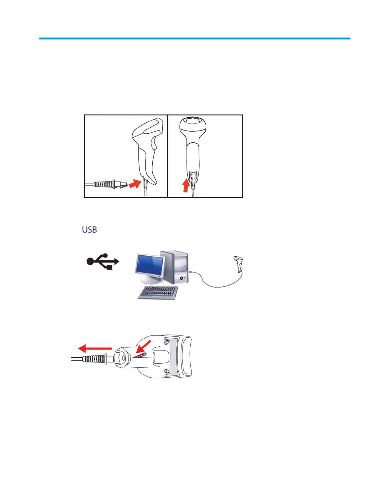
1 Setting up the scanner
Connecting the cable
1. Connect the interface cable to the bottom of the scanner.
2. Connect the other end of the interface cable to a USB connector on the host device.
To disconnect the cable from the scanner, insert a paper clip into the hole in the front of scanner and remove
the cable from the scanner as shown below.
Connecting the cable 1
Page 8
2 Using the scanner
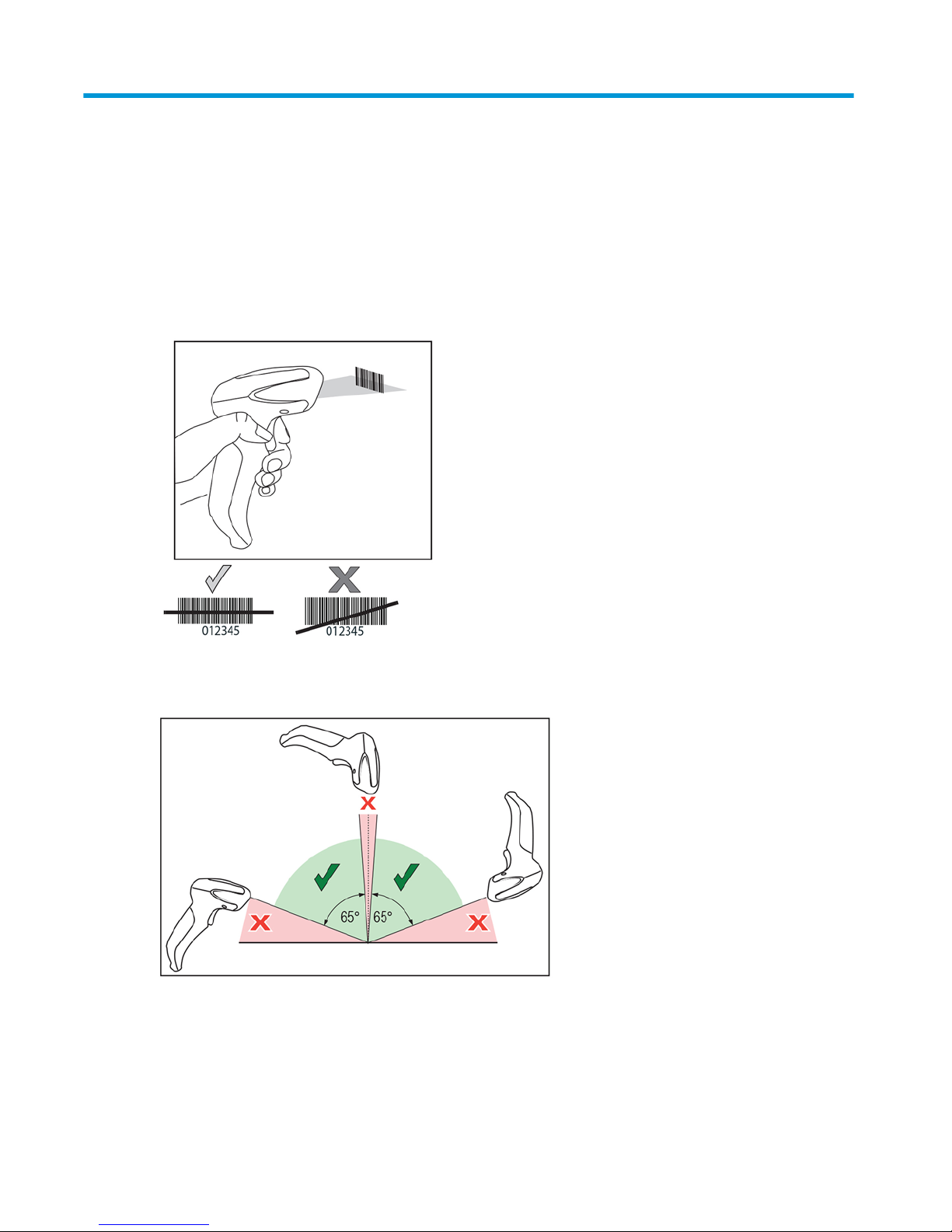
Reading barcodes
Point the scanner at the target and pull the trigger to enable the illuminator (red beam) to decode the barcode
label. The illuminator will remain on until the trigger is released, or a label is read, or the "maximum scan on
time" is reached. When scanning a barcode label, you can adjust the distance or angle to the label to help
facilitate reading. Make sure that the scan line crosses every bar and space of the barcode.
Do not hold the scanner directly over the barcode. Light reecting directly back into the scanner from the
barcode is known as specular reection. This specular reection can make decoding diicult. You can tilt the
scanner up to 65° forward or back and achieve a successful decode.
2 Chapter 2 Using the scanner
Page 9

3 Safety and maintenance
Ergonomic recommendations
WARNING! In order to avoid or minimize the potential risk of ergonomic injury, follow the recommendations
below. Consult with your local Health & Safety Manager to ensure that you are adhering to your company’s
safety programs to prevent employee injury.
●
Reduce or eliminate repetitive motion
●
Maintain a natural position
●
Reduce or eliminate excessive force
●
Keep objects that are used frequently within easy reach
●
Perform tasks at correct heights
●
Reduce or eliminate vibration
●
Reduce or eliminate direct pressure
●
Provide adjustable workstations
●
Provide adequate clearance
●
Provide a suitable working environment
●
Improve work procedures
Ergonomic recommendations 3
Page 10

Cleaning
Exterior surfaces and scan windows exposed to spills, smudges, or debris require periodic cleaning to ensure
best performance during scanning.
Use a soft, dry cloth to clean the product. If the product is very soiled, clean it with a soft cloth moistened with
a diluted non-aggressive cleaning solution or diluted ethyl alcohol.
IMPORTANT: Do not use abrasive or aggressive cleansing agents or abrasive pads to clean scan windows or
plastics.
Do not spray or pour liquids directly onto the unit.
4 Chapter 3 Safety and maintenance
Page 11

4 Programming the scanner
The scanner is factory-congured with a set of standard default features. After scanning the interface
barcode from the “Interfaces” section, select other options and customize your scanner using the
programming barcodes available in the HP Retail Linear Barcode Scanner Programming Reference Guide (PRG).
Check the corresponding features section for your interface, and the Data Editing and Symbologies chapters
of the PRG.
Using programming barcodes
This guide contains barcodes that allow you to recongure your scanner. Some programming barcode labels,
like the Reset Default Settings barcode, require only the scan of that single label to enact the change.
Other barcodes require the scanner to be placed in Programming Mode prior to scanning them. Scan an
ENTER/EXIT barcode once to enter Programming Mode, scan the desired parameter settings, and then scan
the ENTER/EXIT barcode again to accept your changes. The scanner exits Programming Mode and returns to
normal operation.
Conguring other setting
Additional programming barcodes are available in the PRG that allow you to customize programming
features. If your installation requires dierent programming than the standard factory default settings, refer
to the PRG.
Resetting the defaults
If you aren’t sure what programming options are in your scanner, or you’ve changed some options and want
your custom factory settings restored, scan the barcode below to reset the scanner to its initial conguration.
Refer to the PRG for other options and a listing of standard factory settings.
NOTE: Factory defaults are based on the interface type. Be sure your scanner is congured for the correct
interface before scanning this label. See Selecting the interface type on page 6 for more information.
Reset Default Settings
Using programming barcodes 5
Page 12

5 Selecting the interface type
Upon completing the physical connection between the scanner and its host, scan the appropriate barcode to
select your system’s correct interface type. Information and programming options for each interface type are
provided in this chapter. For defaults and additional information, refer to the PRG.
Conguring the interface
Scan the appropriate programming barcode to select the interface type for your system.
NOTE: Unlike some other programming features and options, interface selections require that you scan only
one programming barcode label. DO NOT scan an ENTER/EXIT barcode prior to scanning an interface selection
barcode.
Some interfaces require the scanner to start in the disabled state when powered up. If additional scanner
conguration is desired while in this state, pull the trigger and hold for ve seconds. The scanner will change
to a state that allows programming with barcodes.
USB-COM
USB COM to simulate RS-232 standard interface
Select USB-COM-STD
Download the correct USB Com driver from http://www.hp.com/support.
USB-OEM
USB-OEM
(can be used for OPOS/UPOS/JavaPOS)
Select USB-OEM
6 Chapter 5 Selecting the interface type
Page 13

Keyboard interface
Use the programming barcodes below to select options for a USB keyboard.
Keyboard
USB keyboard with alternate key encoding
Select USB Alternate Keyboard
USB keyboard with standard key encoding
Select USB Keyboard
Scancode tables
Refer to the PRG for information about control character emulation for keyboard interfaces.
Keyboard interface 7
Page 14

Country mode
This feature species the country/language supported by the keyboard. Only USB Keyboard (without alternate
key encoding) supports all country modes.
All other interfaces support ONLY the following country modes: U.S., Belgium, Britain, France, Germany, Italy,
Spain, and Sweden.
Country mode
ENTER/EXIT PROGRAMMING MODE
Country Mode = U.S.
Country Mode = Belgium
Country Mode = Britain
Country Mode = Croatia*
Country Mode = Czech Republic*
Country Mode = Denmark*
8 Chapter 5 Selecting the interface type
Page 15

Country mode
Country Mode = France
Country Mode = French Canadian
Country Mode = Germany
Country Mode = Hungarian
Country Mode = Italy
Country Mode = Japanese 106-key*
Country Mode = Lithuanian
Country Mode = Norway*
Country mode 9
Page 16

Country mode
Country Mode = Poland*
Country Mode = Portugal*
Country Mode = Romania*
Country Mode = Slovakia*
Country Mode = Spain
Country Mode = Sweden
Country Mode = Switzerland*
*Supports only the interfaces listed in the Country Mode feature
description.
10 Chapter 5 Selecting the interface type
Page 17

Caps lock state
This option species the format in which the reader sends character data. This is used by USB keyboard
interfaces.
00 = Caps lock o, send character data in normal format.
01 = Caps lock on, send character data in reverse case.
02 = Auto Caps lock.
Caps lock state
ENTER/EXIT PROGRAMMING MODE
Caps Lock State = Caps Lock OFF
Caps Lock State = Caps Lock ON
Caps Lock State = AUTO Caps Lock Enable
Caps lock state 11
Page 18

6 Reading parameters
Move the scanner toward the target and center the aiming pattern and illumination system to capture and
decode the image. See Using the scanner on page 2 for more information.
The aiming system will briey switch o after the acquisition time, and if no code is decoded will switch on
again before the next acquisition. The illuminator will remain on until the symbol is decoded.
As you read code symbols, adjust the distance at which you are holding the scanner.
Good read green spot duration
Successful reading can be signaled by a good read green spot. Use the barcodes that follow to specify the
duration of the good read pointer beam after a good read.
Good read green spot duration
ENTER/EXIT PROGRAMMING MODE
Green Spot Duration = Disable (Green Spot is O)
Green Spot Duration = Short (300 msec)
Green Spot Duration = Medium (500 msec)
Green Spot Duration = Long (800 msec)
12 Chapter 6 Reading parameters
Page 19

7 Scan modes
The scanner can operate in one of several scanning modes.
Trigger Single: When the trigger is pulled, scanning begins until one of the following occurs:
●
A programmable duration has elapsed
●
A label has been read
●
The trigger is released
●
"Maximum scan on time" is reached
This mode is associated with typical handheld scanner operation.
Trigger Hold Multiple: When the trigger is pulled, scanning begins and the product scans until the trigger is
released, a programmable duration has elapsed, or the "maximum scan on time" is reached. Reading a label
does not disable scanning. "Double read" time-out prevents undesired multiple reads while in this mode.
Trigger Pulse Multiple: Scanning begins when the trigger is pulled and continues after the trigger is released
until the trigger is pulled again or until the "maximum scan on time" is reached or a programmable duration
has elapsed. Reading a label does not disable scanning. "Double read" time-out prevents undesired multiple
reads.
Flashing: The reader ashes on and o regardless of the trigger status. Code reading takes place only during
the ash on time. "Double read" time-out prevents undesired multiple reads.
Always On: The illuminator is always on regardless of the trigger status and the reader is always ready for
code reading. "Double read" time-out prevents undesired multiple reads.
Object Detection: In this mode the scanner looks for scene changes within its eld of view to initiate read
attempts. To help the user nd the position of the reading line, the green spot can be congured to be on.
When an object’s presence is detected in the scene, the illuminator turns on and turns o the green spot.
Scanning continues until the Object Gone Timeout expires after last read. "Double read" time-out prevents
undesired multiple reads while the scanner is in this mode.
Trigger Object Sense: This is similar to Object Detection. A trigger pull is required to activate the decoder.
NOTE: See the Product Reference Guide (PRG) for more information.
Scan mode
Scan Mode = Trigger Single
Scan Mode = Trigger Hold Multiple
13
Page 20

Scan mode
Scan Mode = Trigger Pulse Multiple
Scan Mode = Flashing
Scan Mode = Always On
Scan Mode = Object Detection
Scan Mode = Trigger Object Sense
14 Chapter 7 Scan modes
Page 21

A Technical specications
The following table contains physical and performance characteristics, user environment, and regulatory
information.
Item Description
Physical characteristics
Color Black
Dimensions Height 6.4"/163 mm
Length 3.6"/91 mm
Width 1.6"/41 mm
Weight (without cable) Approximately 5.3 ounces/150 g
Electrical characteristics
Voltage and current
1
Input voltage: 4.5 - 14.0 VDC
Operating (typical): 140 mA
Operating (max): 380 mA
Idle/standby (typical): 50 mA
Performance characteristics
Light source LEDs
Roll (tilt) tolerance
2
Up to ± 45°
Pitch tolerance
2
± 65°
Skew (yaw) tolerance
2
± 70°
Field of view 56 ± 2°
Print contrast minimum 25% minimum reectance
1
Typical input current measured @5V under factory default conguration.
2
Based on ISO 15423 specications.
Depth of eld (guaranteed)
1
Symbology
Code 39 5 mil: 0.8" - 7" (2 cm - 18 cm)
7.5 mil: 0.8"- 12" (2 cm - 30 cm)
10 mil: 0.8" - 17" (2 cm - 44 cm)
20 mil: up to 29.5" (75 cm)
EAN 13 mil: 0.8" - 23" (2 cm - 58 cm)
15
Page 22

Depth of eld (guaranteed)
1
Minimum element width Max Resolution = 4 mil
1
13 mils DOF based on EAN. All other 1D codes are Code 39. All labels grade A, typical environmental
light, 20°C, label inclination 10°
Decode capability
1D barcodes
UPC/EAN/JAN (A, E, 13, 8); UPC/EAN/JAN (including P2 /P5); UPC/EAN/JAN (including ISBN / Bookland &
ISSN); UPC/EAN Coupons; Code 39 (including full ASCII); Code 39 Trioptic; Code39 CIP (French
Pharmaceutical); LOGMARS (Code 39 w/ standard check digit enabled); Code 32 (Italian Pharmacode 39);
Code 128; Code 128 ISBT; Interleaved 2 of 5; Standard 2 of 5; Interleaved 2 of 5 CIP (HR); Industrial 2 of
5; IATA 2 of 5 Air cargo code; Datalogic 2 of 5, Code 4, Code 5, Follet 2 of 5, BC412, Code 11; Codabar;
Codabar (NW7); ABC Codabar; EAN 128; Code 93 ; MSI; PZN; Plessey; Anker Plessey; GS1 DataBar
Omnidirectional; GS1 DataBar Limited; GS1 DataBar Expanded; GS1 DataBar Truncated; DATABAR
Expanded Coupon.
Interfaces supported Keyboard Wedge, USB Com Std., USB Keyboard, USB OEM
User environment
Operating temperature 0°C to 50°C (32°F to 122°F)
Storage temperature -40°C to 70°C (-40°F to 158°F)
Humidity Operating: 0% to 95% relative humidity, non-condensing
Drop specications Scanner withstands 18 drops from 1.5 meters (5.0 feet) to
concrete
Ambient light immunity Up to 120,000 Lux
Contaminants spray/rain/dust/particulates IEC 529-IP42
16 Appendix A Technical specications
Page 23

B LED and beeper indications
The scanner’s beeper sounds and its top multi-color LED illuminates to indicate various functions or errors. An
optional “green spot” also performs useful functions. The following tables list these indications. One
exception to the behaviors listed in the tables is that the scanner’s functions are programmable, and so may
or may not be turned on. For example, certain indications such as the power-up beep can be disabled using
programming barcode labels.
Indicator Description LED Beeper
Power-up beep The scanner is in the process of
powering up.
N/A Scanner beeps four times at
highest frequency and volume
upon power up.
Good read beep A label has been successfully
scanned.
LED behavior for this indication
is congurable via the feature
“Good Read: When to Indicate”
(see the PRG for information).
The scanner will beep once at
current frequency, volume,
mono/bitonal setting and
duration upon a successful
label scan.
ROM failure There is an error in the
scanner’s software/
programming.
Flashes. Scanner sounds one error beep
at highest volume.
Limited scanning label read Indicates that a host
connection is not established.
N/A Scanner “chirps” six times at
the highest frequency and
current volume.
Scanner active mode The scanner is active and ready
to scan.
The LED is steadily lit1.
N/A
Scanner disabled The scanner has been disabled
by the host.
The LED blinks continuously. N/A
Green spot1 ashes
momentarily
Upon successful read of a label,
the software turns the green
spot on for the time specied
by the congured value.
N/A N/A
1
Except when in sleep mode or when a Good Read LED Duration other than 00 is selected.
Programming mode - The following indications ONLY occur when the scanner is in programming mode.
Indication Description LED Beeper
Label programming mode entry A valid programming label has
been scanned.
LED blinks continuously. Scanner sounds four low-
frequency beeps.
Label programming mode
rejection of label
A label has been rejected. N/A Scanner sounds three times at
lowest frequency and current
volume.
Label programming mode
acceptance of partial label
In cases where multiple labels
must be scanned to program
one feature, this indication
acknowledges each portion as
it is successfully scanned.
N/A Scanner sounds one short beep
at highest frequency and
current volume.
17
Page 24

Indication Description LED Beeper
Label programming mode
acceptance of programming
Conguration option(s) have
been successfully programmed
via labels and the scanner has
exited programming mode.
N/A Scanner sounds one high-
frequency beep and four lowfrequency beeps followed by
reset beeps.
Label programming mode
cancel item entry
Cancel label has been scanned. N/A Scanner sounds two times at
low frequency and current
volume.
Error codes
Upon startup, if the scanner sounds a long tone, this means the scanner has not passed its automatic Selftest
and has entered FRU (Field Replaceable Unit) isolation mode. If the scanner is reset, the sequence will be
repeated. Press and release the trigger to hear the FRU indication code.
The following table describes the LED ashes/beep codes associated with an error found.
Number of LED ashes/beeps Error Corrective action
1 Conguration Contact Helpdesk for assistance.
2 Interface PCB Contact Helpdesk for assistance.
6 Digital PCB Contact Helpdesk for assistance.
11 Imager Contact Helpdesk for assistance.
18 Appendix B LED and beeper indications
Page 25

C Technical support
Contacting support
To resolve a hardware or software problem, go to http://www.hp.com/support. Use this site to get more
information about your product, including links to discussion forums and instructions on troubleshooting. You
can also
nd information on how to contact HP and open a support case.
Preparing to call technical support
If you can not solve a problem, you may need to call technical support. Have the following information
available when you call:
●
If the product is connected to an HP POS computer, provide the serial number of the POS computer
●
Purchase date on invoice
●
The spares part number located on the product
●
Condition under which the problem occurred
●
Error messages received
●
Hardware conguration
●
Name and version of the hardware and software you are using
Contacting support 19
 Loading...