

Page 1

HP Library and Tape Tools v4.17 User Guide
Abstract
HP Library and Tape Tools (L&TT) is a comprehensive application that provides functions for identifying, testing, updating, and
troubleshooting a wide variety of data storage hardware and media.
HP Part Number: EH957-90960
Published: July 2014
Edition: 1
Page 2

© Copyright 2002, 2014 Hewlett-Packard Development Company, L.P.
Hewlett-Packard Company makes no warranty of any kind with regard to this material, including, but not limited to, the implied warranties of
merchantability and fitness for a particular purpose. Hewlett-Packard shall not be liable for errors contained herein or for incidental or consequential
damages in connection with the furnishing, performance, or use of this material.
This document contains proprietary information, which is protected by copyright. No part of this document may be photocopied, reproduced, or
translated into another language without the prior written consent of Hewlett-Packard. The information contained in this document is subject to
change without notice.
Compaq Computer Corporation is a wholly-owned subsidiary of Hewlett-Packard Company.
Microsoft®, MS-DOS®, MS Windows®, Windows®, and Windows NT® are U.S. registered trademarks of Microsoft Corporation.
UNIX® is a registered trademark of The Group.
Hewlett-Packard Company shall not be liable for technical or editorial errors or omissions contained herein. The information is provided “as is”
without warranty of any kind and is subject to change without notice. The warranties for Hewlett-Packard Company products are set forth in the
express limited warranty statements for such products. Nothing herein should be construed as constituting an additional warranty.
Page 3

Contents
1 Introduction...............................................................................................9
Software features......................................................................................................................9
What's new...........................................................................................................................10
Known issues and limitations in L&TT 4.17..................................................................................11
Supported products and operating systems................................................................................13
Finding additional information..................................................................................................13
2 Using L&TT on Windows...........................................................................14
Installing L&TT........................................................................................................................14
Windows installation prerequisites.......................................................................................14
Installation procedure.........................................................................................................14
Using the graphical user interface.............................................................................................15
Starting L&TT.....................................................................................................................16
Scan Mode..................................................................................................................16
Hardware Scan........................................................................................................16
Saved/Manual scan.................................................................................................17
Additional device scan considerations.........................................................................18
I/O mode....................................................................................................................18
Skip this dialog in the future...........................................................................................19
Check for backup applications and services......................................................................19
Application window layout..................................................................................................20
Using the Device Information screen ....................................................................................21
Standalone devices.......................................................................................................21
Library and autoloader products.....................................................................................23
Using the firmware management screen ...............................................................................24
Get files from web functionality............................................................................................25
Checking firmware versions............................................................................................25
Viewing firmware revision history....................................................................................25
Managing firmware ...............................................................................................................25
Acquiring firmware files......................................................................................................25
Selecting and downloading updated firmware files.................................................................26
Uploading firmware to devices............................................................................................27
Advanced options..............................................................................................................28
Using test screen................................................................................................................29
Running tests and device-specific utilities..........................................................................29
Viewing results.........................................................................................................30
Aborting a test.........................................................................................................31
Using the utility screen........................................................................................................32
Using the support ticket screen.............................................................................................33
Extracting a support ticket..............................................................................................34
Saving a report or support ticket.....................................................................................34
Viewing a report or support ticket....................................................................................34
Sending a report or support ticket by email......................................................................35
Prerequisites............................................................................................................36
3 Using L&TT on non-Windows systems..........................................................38
Installation.............................................................................................................................38
Installing L&TT for Linux.......................................................................................................38
Installing L&TT for HP-UX.....................................................................................................39
Installing L&TT for HP VMS..................................................................................................40
Installing L&TT for Solaris....................................................................................................40
Installing L&TT for Mac.......................................................................................................41
Contents 3
Page 4

Using the command screen interface (CSI).................................................................................41
Starting L&TT.....................................................................................................................42
Navigating the screens ......................................................................................................42
Using the scan mode selection screen...................................................................................43
Using the saved and manual scan screen..............................................................................44
Using the device information screen ....................................................................................45
Managing firmware................................................................................................................47
Accessing details for local firmware files...............................................................................48
Acquiring firmware files......................................................................................................48
Using the get files from web functionality..........................................................................49
Uploading firmware to devices............................................................................................49
Advanced options..............................................................................................................50
Running the tests and utilities....................................................................................................50
Viewing test results.............................................................................................................52
Aborting a test..................................................................................................................53
Using reports and support tickets..............................................................................................54
Generating and viewing a support ticket...............................................................................54
Support ticket compression.............................................................................................55
Sending a support ticket by email (CSI)............................................................................55
Loading or opening support tickets..................................................................................56
Generating an XML support ticket....................................................................................56
Using the SCSI script utilities...........................................................................................57
Generating an event log................................................................................................58
Viewing an event log.....................................................................................................58
4 Command line functionality.......................................................................59
Overview..............................................................................................................................59
Running multiple instances of L&TT.......................................................................................59
Running L&TT commands from removable media....................................................................60
Command line functions..........................................................................................................60
Configuring L&TT ..............................................................................................................61
Scanning the bus ..............................................................................................................62
Listing supported tests (CLF).................................................................................................63
Running tests (CLF).............................................................................................................64
Performing a firmware update..............................................................................................66
Generating a report or support ticket (CLF)............................................................................67
Converting a support ticket to XML (CLF)...............................................................................69
Return values..........................................................................................................................70
Using the trace file.............................................................................................................70
5 Tests.......................................................................................................71
Diagnostic tests......................................................................................................................71
Drive Specific tests.............................................................................................................72
Drive Assessment test.....................................................................................................72
Device Analysis test.......................................................................................................73
Media Specific tests...........................................................................................................74
Media Analysis test.......................................................................................................74
LTO Media Assessment Full Tape test................................................................................75
Media Validation test.....................................................................................................76
MO Media Validation test..............................................................................................77
LTO Stuck Tape test........................................................................................................77
LTO Media Assessment test.............................................................................................78
LTO Data Assessment test...............................................................................................78
Library Specific tests support ticket........................................................................................79
Library Exerciser test......................................................................................................79
Using the Library Exerciser test...................................................................................80
4 Contents
Page 5

Library Read Write test...................................................................................................82
ESL Vendor ID test.........................................................................................................85
Other tests........................................................................................................................85
Installation Check test....................................................................................................86
Connectivity test............................................................................................................86
LTO Cooling Check test..................................................................................................87
Data Compression test...................................................................................................87
LTO Encryption test........................................................................................................88
Device Configuration test................................................................................................88
Device Self-test..............................................................................................................89
Move test.....................................................................................................................90
Read/Write Stress test...................................................................................................90
Full Sweep test..............................................................................................................91
Read/Write test............................................................................................................91
Initialize Element Status test............................................................................................92
Restore Factory Default Settings test.................................................................................93
Performance tests....................................................................................................................94
Using the Drive Performance test..........................................................................................94
Running on non-Windows..............................................................................................97
Using the System Performance test........................................................................................99
Performing the System Performance Restore Performance test (GUI).......................................99
Performing the System Performance Backup Performance test.............................................101
Performing the System Performance tests (CSI) running in non-Windows..............................103
DDS Assessment test...............................................................................................104
DAT320 Encryption test...........................................................................................106
SDLT Tape Edge Damage (TED) test..........................................................................106
Full Sweep test.......................................................................................................107
DLT SRAM Check test (short and long versions)...........................................................107
DDS Media Assessment test.....................................................................................108
DDS Cooling test....................................................................................................109
Autoloader Exerciser test.........................................................................................110
Utility functions.....................................................................................................................110
Device Specific utility descriptions......................................................................................110
Compare Statistics utility..............................................................................................111
Device Configuration test..............................................................................................111
Firmware Tape Creator (FUP tape) utility.........................................................................112
Force Tape Eject utility.................................................................................................112
LTO6 EEPROM download utility....................................................................................112
LTO Firmware to Data Tape Creator...............................................................................113
Read Media IDs..........................................................................................................113
Tape Erase utility.........................................................................................................113
Re-initialize LTFS tape...................................................................................................114
DAT Autoloader Firmware Tape Creator.........................................................................114
6 Reports and support tickets......................................................................115
Common information reported for all products..........................................................................116
Understanding LTO support tickets...........................................................................................116
System information...........................................................................................................117
Reading LTO drive support tickets.......................................................................................118
Drive identity...................................................................................................................119
STTF support ticket...........................................................................................................119
Understanding STTF support ticket.................................................................................120
7 Additional functionality...........................................................................122
Setting software preferences...................................................................................................122
Available options.............................................................................................................124
Contents 5
Page 6

Using the Internet update functionality.....................................................................................126
Finding customer advisories and notifications...........................................................................126
Using passwords..................................................................................................................128
Setting passwords............................................................................................................128
Using the Front Panel function.................................................................................................128
Using the Move Media function..............................................................................................129
Possible Move Media error situations..................................................................................130
Performing manual product identification.................................................................................131
Running the device independent utilities...................................................................................131
System Config utility.........................................................................................................133
Running plugins....................................................................................................................133
Using the quiet mode feature.................................................................................................134
Using the installation check feature.........................................................................................134
Managing the TapeAssure service..........................................................................................136
Using L&TT in restricted mode.................................................................................................137
Using the Tool Status Report...................................................................................................137
8 Advanced installation topics....................................................................140
Other changes to the system (GUI)..........................................................................................140
Reboot criteria......................................................................................................................140
Running L&TT from computers without L&TT installed..................................................................140
Running L&TT from a CD or USB flash drive.........................................................................140
Running L&TT from a shared directory.................................................................................141
Files installed on the system....................................................................................................142
Other changes to the system (CSI)......................................................................................143
9 Accessing HP library LTO-5 and LTO-6 drives over Ethernet..........................144
Supported operating systems, devices, and operations..............................................................144
Connecting to the Ethernet port..............................................................................................144
Known issues and limitations..................................................................................................146
10 Frequently asked questions.....................................................................147
General questions.................................................................................................................147
Where can I find LTT?.......................................................................................................147
How do I install L&TT?......................................................................................................147
What is the impact of my server if I install LTT?....................................................................147
Why should I use LTT?......................................................................................................147
Why should I use latest version of LTT?................................................................................148
How do I get to know the latest version of LTT?....................................................................148
What Operating Systems & drive generation LTT supports?....................................................148
If I have any problems in using LTT how I can contact?..........................................................148
What information I should provide when contacting HP support?...........................................148
Where can I find information about media compatibility with my hardware?...........................148
Where can I find information about hardware and software compatibility?..............................149
Drive & Firmware Questions...................................................................................................149
Why I should use LTT for firmware upgrade?........................................................................149
How do I verify that my drive's firmware is up to date?.........................................................149
Where can I find information about drive cleaning requirements?...........................................149
How do I use L&TT to find my drive serial number?...............................................................150
How do I check if my drive is OK?.....................................................................................150
How do I know if drive is degrading?.................................................................................150
When the drive should be replaced?..................................................................................150
Support ticket questions.........................................................................................................150
Why HP support ask for support ticket?...............................................................................150
How do I generate support ticket in Windows?....................................................................150
How do I generate support ticket in Non Windows?.............................................................150
6 Contents
Page 7

How do I send a support ticket?.........................................................................................151
Tests questions......................................................................................................................151
Why should I run L&TT tests?.............................................................................................151
Why should I stop the backup/restore activity when running LTT tests?....................................151
Does all tests required to stop the backup & restore activities?................................................151
How do I know which test to run?......................................................................................151
Why is the Assessment test recommended?..............................................................................151
Backup and restore questions.................................................................................................151
Was my backup successful (LTO only)?...............................................................................152
How fast will my backups be?...........................................................................................152
How fast will my restores be?............................................................................................152
How do I send an L&TT event log?.....................................................................................152
If backup/restore fails what I should do?.............................................................................152
How LTT can help to identify the problems during backup/restore?.........................................152
Media questions...................................................................................................................152
Is my LTO tape OK?.........................................................................................................153
Is my non-LTO tape OK?...................................................................................................153
How do I verify the capacity of a tape?..............................................................................153
How many more uses are left in this cleaning cartridge (LTO only)?........................................153
How do I send an L&TT event log?.....................................................................................153
Windows questions ..............................................................................................................154
Why can't I uninstall L&TT or install a new version?..............................................................154
How do I run L&TT from a CD or USB flash drive?................................................................154
How do I shut down the application in the taskbar?..............................................................154
When installing L&TT for Windows, should I uninstall my previous version first?........................155
How do I erase an LTO FUP tape?......................................................................................155
How do I configure email to send support tickets?................................................................155
Does L&TT use any system resources in the background?.......................................................155
I am using an authenticated proxy at my site. How do I configure L&TT to connect to the HP website
to download firmware updates?.........................................................................................155
L&TT starts in restricted mode and most functionality is unavailable. What is happening?..........156
Why doesn't L&TT for Windows see devices that are connected to a computer running HP-UX?...156
Why doesn't L&TT for Windows see my USB drives?.............................................................156
CSI questions ......................................................................................................................156
How do I set the password?..............................................................................................157
Why does my display not show any text or only a single line of text on my HP-UX system?.........157
Why is there a segmentation fault when L&TT is initiated in HP-UX?........................................157
Why doesn't L&TT for HP-UX see some of my devices?..........................................................157
Why doesn't L&TT for HP-UX see all the devices connected to a SAN environment?...................158
Why am I unable to download firmware/script files using the download option in the CSI (HP-UX,
Linux)?............................................................................................................................158
Why doesn't L&TT for Tru64 see some of my devices?...........................................................158
Why doesn't L&TT for Linux see some of my devices?............................................................158
Why doesn't L&TT for Windows see devices that are connected to a computer running HP-UX?...159
How do I connect/disconnect a SCSI device in Linux without rebooting?.................................159
Why doesn't L&TT for VMS see my media changer?.............................................................159
Why am I getting Error activating image PTHREAD$RTL while running L&TT on VMS 7.3-1?.......159
11 Troubleshooting....................................................................................160
Troubleshooting L&TT............................................................................................................160
Troubleshooting devices.........................................................................................................160
Using L&TT to troubleshoot tape devices..............................................................................160
Are you performing regular maintenance?......................................................................161
Is the drive connected properly?....................................................................................161
Is the drive working as expected?..................................................................................162
Contents 7
Page 8

Is the drive firmware up to date?...................................................................................162
Is the drive working as expected?..................................................................................162
Is the media in good condition?....................................................................................162
Additional interactive device troubleshooting content............................................................163
Troubleshooting third-party software........................................................................................163
12 Support and other resources...................................................................164
Getting support....................................................................................................................164
Contacting HP......................................................................................................................164
Other HP websites................................................................................................................164
A Operating system support........................................................................165
B Discontinued products.............................................................................166
C Using a firmware update (FUP) tape.........................................................167
Performing the update...........................................................................................................167
SDLT..............................................................................................................................167
DLT VS80/DLT1...............................................................................................................168
DLT 4000/7000/8000....................................................................................................169
Ultrium...........................................................................................................................170
HP DDS/DAT..................................................................................................................170
Compaq/Sony AIT & DDS................................................................................................171
Converting a firmware update tape to a data tape....................................................................171
D Support ticket fields................................................................................172
Drive health.........................................................................................................................172
Drive configuration...............................................................................................................173
Drive environment.................................................................................................................173
Drive performance................................................................................................................174
Drive usage.........................................................................................................................174
Drive history.........................................................................................................................175
Cartridge identity.................................................................................................................176
Cartridge health...................................................................................................................176
Cartridge configuration.........................................................................................................176
Cartridge environment...........................................................................................................177
Cartridge performance..........................................................................................................177
Cartridge usage...................................................................................................................177
Cartridge history..................................................................................................................178
Classic support ticket.............................................................................................................178
Index.......................................................................................................179
8 Contents
Page 9

1 Introduction
HP Library and Tape Tools (L&TT) is a collection of storage hardware management and diagnostic
tools for HP tape mechanisms, tape automation, magneto-optical and archival products. L&TT
assembles these tools into a single and convenient program.
• “Software features” (page 9)
• “What's new” (page 10)
• “Known issues and limitations in L&TT 4.17” (page 11)
• “Supported products and operating systems” (page 13)
• “Finding additional information” (page 13)
Software features
L&TT offers the following features:
• Installation check—L&TT guides you through a basic installation check of your product. The
software assists the user in choosing an appropriate HBA and SCSI IDs, ensuring that the
device is detected by the system, and verifying the key device functionality.
• Device identification—L&TT clearly identifies the storage products connected to the system,
along with the key information on the product configuration and status.
• Troubleshooting tests—L&TT provides various tests to verify product functionality or to isolate
product issues. The tests include device self-tests, read/write tests on drives, exerciser tests for
autoloaders and libraries, and specific device utilities.
• Firmware upgrades—L&TT provides a convenient way of updating product firmware, enabling
users with an internet connection to take advantage of ongoing enhancements. The software
is configured to check the web automatically for firmware updates for connected devices, or
users can manually check the web for updates, if the automatic update feature is not desired.
If updated firmware is available, the program notifies the user, and the updates are easily
copied to the system. With libraries, users can upgrade the library and the embedded drive
firmware in the same operation.
• Reports and support tickets—If you experience a problem with a storage product, L&TT can
generate a support ticket or report that includes essential information for troubleshooting the
problem.
◦ Support tickets—The support tickets contain log data and other information that is primarily
intended for HP support personnel and developers.
◦ Reports—The use of reports and support tickets is essentially the same. The main difference
is that reports have an enhanced format that presents more useful information to the user.
As an alternative to phone support, you can email the support ticket to a support center
for assistance. This information streamlines the support process and enables the support
staff to serve you better. When a support ticket for a device is generated, L&TT performs
a Device Analysis test on the device. The support ticket contains generic information about
a device, as well as the results of the Device Analysis test. The Device Analysis test is
easy to perform, but HP recommends generating a support ticket, because the resulting
Software features 9
Page 10

• Automatic notification of web updates—If a connection to the Internet is present and web
updates are enabled in the tool preferences, L&TT automatically informs customer of the
following updates, if available, each time the program is started:
◦ New versions of L&TT.
◦ New firmware files for connected devices.
◦ New device-specific functionality for connected devices.
What's new
What's new in L&TT 4.17
L&TT 4.17 is an incremental release that targets:
• STTF (save trace to flash) support ticket for LTO-6 drive. See “STTF support ticket” (page 119).
• Improved data assessment test. See “LTO Data Assessment test” (page 78).
• Support for the latest ESL G3 and MSL6480 firmware versions.
Enhancements and fixes in L&TT 4.17
data is presented in a more useful format. Reports and support tickets are generated on
all operating systems supported by L&TT.
• Tape Libraries
Updated ESL G3 RAS repair pages.◦
◦ Added more information for ESL G3 and MSL6480 library support ticket decoding.
• Tape Drives
Included latest version of RDX utility.◦
◦ Improved screening for over-temp readings.
◦ Included the part number for drives to help identify correct spare.
◦ Updated the Identity screen to show the full or half height drives.
◦ Added ERT auto boost phase for all ERT based tests.
◦ Improved device analysis rule.
◦ EOD pages displayed for all partitions in the support ticket.
◦ Support ticket displays FVE (full volume equivalent) under cartridge usage.
◦ Updated temperature margin calculation.
10 Introduction
Page 11

• Operating system specific
Support for Windows 2012 R2◦
◦ Support for Windows 8.1
◦ Support for Mac OSX 10.9
• Generic to tool
Added message to inform users about the result log.◦
◦ Added more clarity for representation of time in event logs.
◦ Added a warning message for shutting down backup applications at the start of the
application.
Known issues and limitations in L&TT 4.17
Virtual libraries and D2D
• L&TT supports the most recent releases of D2D emulated drives is broken for all emulated LTO
drive types, due to a change within the drive emulation behavior and therefore cannot be
worked around with previous versions of L&TT.
• L&TT support is limited to what can be done with emulated devices. Use the relevant Command
View GUI to access the support information for the physical device.
Tape libraries
• The MSL6480 currently does not support the Device Self-test.
• Ethernet access specifics:
Minimum firmware versions for LTO-5 drives: I58W, Y58W, Z58W◦
◦ Minimum firmware versions for LTO-6 drives: J27W, J2AS, 22CW, 32AW
◦ Firmware update over Ethernet, updates the firmware but the drives are not rediscovered
by the library on completion. HP recommended to use Command View TL or the MSL
RMI for updating the drive firmware in the libraries.
◦ Drive and L&TT behavior is unpredictable (and not fully tested) when the drive is being
used at the same time that L&TT is talking to it. It is recommended that the library is inactive
when using L&TT over Ethernet, as is recommended for the host access.
• In the front panel window, the ESL G3 library shows LTO-6 drives as LTO-5 drives. This is a
library firmware issue and will be fixed in a future library firmware release.
• The ESL G3 tape library does not offer diagnostic access over its host interface, which limits
L&TT to standard functionality. This still allows most of the library tests to be run, but pulling
tickets and updating firmware is not supported. To pull tickets and update library firmware
use Command View TL. Access to the drives is unchanged and full functionality is available.
• When using L&TT on a Linux operating system, firmware downloads to an MSL2024 Library
may fail. If this happens, the firmware does get downloaded to the unit, but L&TT fails to reflect
the status of the unit when the download completes.
Known issues and limitations in L&TT 4.17 11
Page 12

• In a library with mixed drive technologies, drive firmware cannot be downloaded from the
library firmware download screen. Each drive must be selected individually for download
(Future enhancement).
• If a device is in a 'Not Ready' state, L&TT may not be able to perform all diagnostic functions.
Most devices are only very briefly in this state, but some libraries can take a significant amount
of time after power-up or after a firmware download before becoming ready. If this problem
is encountered, wait until the device is in a ready state and then use L&TT. (Future enhancement)
Autoloaders
• DAT72x6—After using the L&TT front panel and then closing L&TT, the autoloader is left
‘locked'. This is expected product behavior. The work around is to eject the magazine to
unlock.
• DDS2/3/4 autoloaders do not function in L&TT with the option switch value set to return the
standalone drive ID. This causes an ‘unsupport product' response. L&TT works fine with the
switch in the default position. This is an expected product behavior.
Tape drives
• USB devices—Hot plugging a device (such as a USB memory stick) on the same USB bus as
a Tape Drive causes a bus reset. Any test in progress on the drive may fail.
• DLT 8000—Firmware upgrade appears to fail with LSI U320 HBA. It does actually upgrade
OK. Using firmware upgrade tape works fine.
• LTO-6 drive—Part number is not displayed in the support ticket.
Operating system specific
• Windows—Device scan fails intermittently with 'Unexpected Win32 error encountered during
I/O scanning: 2' error message. To work around this problem, perform a full rescan.
• Windows Vista, Windows 2007 and Windows 2008—L&TT at times APPCRASH on exit.
• Windows—If installing with Microsoft Installer package 4.5, manually uninstall the previous
version else the installation remains incomplete.
• HP-UX—Running the LTO Drive Assessment test on multiple drives concurrently can cause a
core dump. The exact number is not known but is in the region of 8 or more.
• Linux in CLF (command line) mode—LTO Drive Assessment test output scrolls off the screen at
the end of the test. Test results are found in the ResultLog.ltt files.
• Mac—Device performance tests are limited to approximately 220 MB/s. L&TT fails to check
the availability of the latest firmware as the Get files from web feature is not supported.
• OpenVMS—L&TT fails to check the availability of the latest firmware as the Get files from web
feature is not supported.
• VMware—L&TT has limited testing and support for standalone SAS drives and all libraries.
The install check and system performance tests are not supported and therefore, no known
issues can be found.
Generic to tool
• There is some inconsistency between the reporting of data capacity and volume between tests.
• If L&TT fails to automatically verify successful completion of a firmware update and is re-selected
12 Introduction
Some tests report data are based on the power of 10, whereas the other report data based
on the power of 2. L&TT is transitioning to the power of 10–based reporting to match industry
specifications.
from the previous scan, L&TT may exit with an exception. The possible cause is that the
Page 13

operating system has performed its own rescan and logically moved the device after the
update. If this happens, use L&TT rescan to locate the device. In these cases the firmware
update is successful.
Supported products and operating systems
For a complete listing of compatible products, see the specifications page: http://www.hp.com/
support/lttcompatibility
The level of functionality that L&TT offers for each device varies, depending on the features of the
device, and the degree of device integration into L&TT.
For a list of supported operating systems, “Operating system support” (page 165).
Finding additional information
The HP website provides the current version of L&TT for download, and general information about
the tool. For more information, see
http://www.hp.com/support/tapetools
Supported products and operating systems 13
Page 14

2 Using L&TT on Windows
• “Installing L&TT” (page 14)
• “Using the graphical user interface” (page 15)
• “Managing firmware ” (page 25)
Installing L&TT
The Windows version of L&TT uses the InstallShield application. InstallShield allows you to choose
the installation directory and select other options. It also sets up shortcuts to launch the application
in the Start menu and on the desktop. The Start menu shortcuts provide access to the online help,
the readme file, the report viewer, and the L&TT installation check features.
Windows installation prerequisites
Device drivers for the connected tape devices or libraries or default device driver must be present.
Reboot requirements A reboot is required only if your system requires ASPI or an upgrade
to the currently installed version. On systems that require ASPI, if
the installer detects a previously installed version of ASPI older than
v4.57, it will install a more recent version of ASPI, that requires a
reboot.
On Windows NT and 2000, ASPI is not installed as part of the
operating system. If a reboot is unacceptable, do not select the
checkbox for this option in the installation process. If you choose
not to install ASPI, you must use the Miniport driver (Miniport I/O
mode) to scan for devices.
You may identify issues, when using the Miniport I/O mode with
devices that use non-standard OS drivers, or are part of the other
applications or the OS. When using the Miniport I/O mode when
a device is claimed, it may be necessary to shut down any running
backup or storage application services to make the device
accessible to L&TT. Alternatively, using the ASPI I/O mode may
make the device accessible without requiring any further action.
Installation procedure
To install the current Windows version of L&TT:
1. Download or copy the self-extracting executable file to a temporary location.
IMPORTANT: Do not rename this file. Renaming the file prevents L&TT from installing.
2. Double-click the self-extracting executable file to launch the installer. The InstallShield Wizard
screen appears.
14 Using L&TT on Windows
IMPORTANT:
• When downloading the L&TT application from the web to your
local system, make sure to rename the download folder. The
installation will fail if you try to install from the Library and Tape
Tools folder. The error indicates that a different instance of the
installer is running.
• Do not rename the L&TT installation file. This prevents L&TT
from installing.
Page 15
3. Click Next. Read the program license agreement and click Yes to accept the terms of the
license agreement.
4. Read the readme file for any last-minute changes to the documentation, then click Next. The
Select Features screen is displayed.
5. Select the desired components to install and click Next.
6. Select a destination location to install the program. You can accept the default location or
click Browse to install to a different location. After choosing the destination location, click
Next.
7. Indicate the program directory in which you want the setup program to create program icons
and click Next. The program directory is created in the Programs directory of the Start menu.
8. On the Ready to start installation process screen, click Next. If you need to review or change
installation settings, click Back.
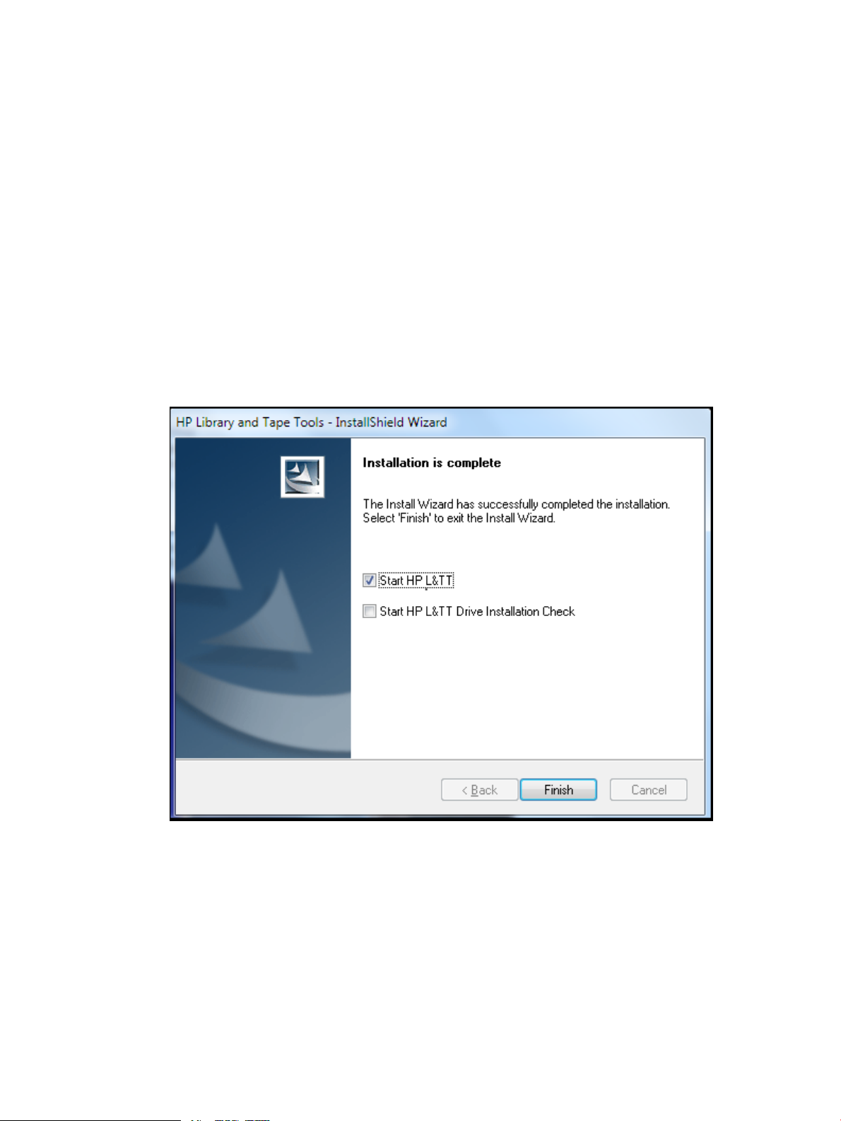
9. When installation is complete, the InstallShield wizard appears. Select Start HP L&TT or Run
LTT InstallCheck if you would like the wizard to start L&TT. For more information on installation,
see “Installation Check test” (page 86).
10. Click Finish to close the InstallShield Wizard as shown in Figure 1 (page 15).
Figure 1 HP Library and Tape Tools InstallShield Wizard
Using the graphical user interface
• “Starting L&TT” (page 16)
• “Application window layout” (page 20)
• “Using the Device Information screen ” (page 21)
• “Using the firmware management screen ” (page 24)
• “Get files from web functionality” (page 25)
Using the graphical user interface 15
Page 16
Starting L&TT
1. Launch the HP L&TT by double-clicking the L&TT shortcut icon on the desktop or click Start >
Programs > HP Library and Tape Tools > HP L&TT.
2. Login with the UserName and Password.
NOTE: The default username and password is administrator and administrator respectively.
3. Click Sign In. The HP L&TT Startup screen is displayed.
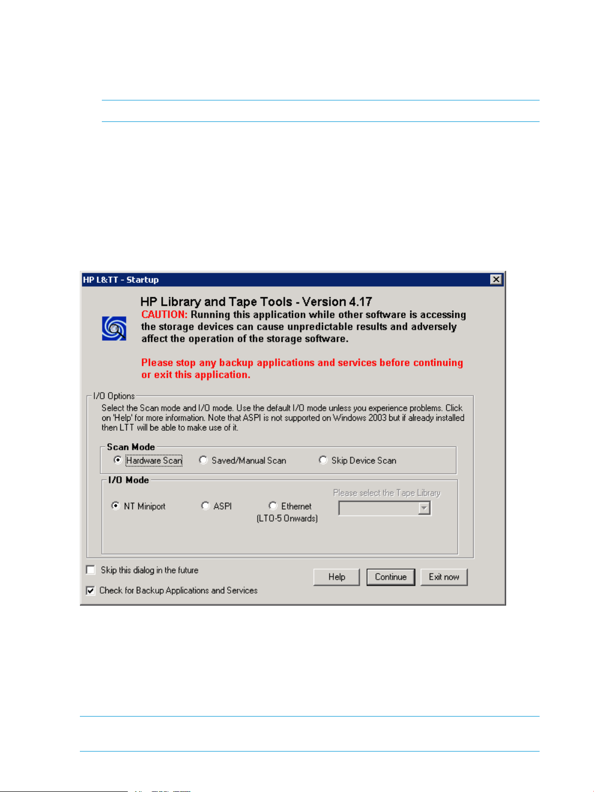
The Startup screen gives you the opportunity to exit the application if it was started unintentionally
and before any SCSI bus activity occurs. This prevents the program from interfering with any backup
or other storage applications that is currently running as shown in Figure 2 (page 16). The Startup
screen allows you to select the initial scan mode and the SCSI I/O mode (if more than one option
is available).
LTT displays a warning message to shut down any backup applications and services at the start
of the application.
Figure 2 HP L&TT Startup screen with warning message
Scan Mode
Hardware Scan
When your application starts for the first time it performs a device scan to identify all the devices
connected to the computer, either directly or through a SAN. The first time L&TT is run, it performs
a full hardware scan (Hardware Scan option) and the results of the scan are automatically
saved. When starting L&TT next time, the Saved/Manual Scan option can be used.
NOTE: If the Saved/Manual Scan option is selected before a hardware scan is done, the list
of available devices will be empty.
16 Using L&TT on Windows
Page 17
SelectingSkip Device Scan, will skip the hardware scan and the I/O Mode buttons are
disabled. With this mode, no devices will be listed on the main screen. Click the Rescan button in
the main screen to scan the connected devices.
NOTE: Selecting the Skip this dialog in the future checkbox on the Startup screen will perform
a full hardware scan. To re-enable the Startup screen and change the scan option, select Preferences
from the Options menu. Check the Display initial dialog at startup option and restart L&TT. Select
multiple devices to be scanned from the Saved/Manual Scan screen. In addition, you can
automatically save device selections and reuse them in a later session. To access the Saved/Manual
Scan screen, select the Saved/Manual Scan option and click Continue on the Startupscreen. If
I/O mode is Ethernet, saved/manual scan is not available.
In large SAN environments, a full scan takes a long time.
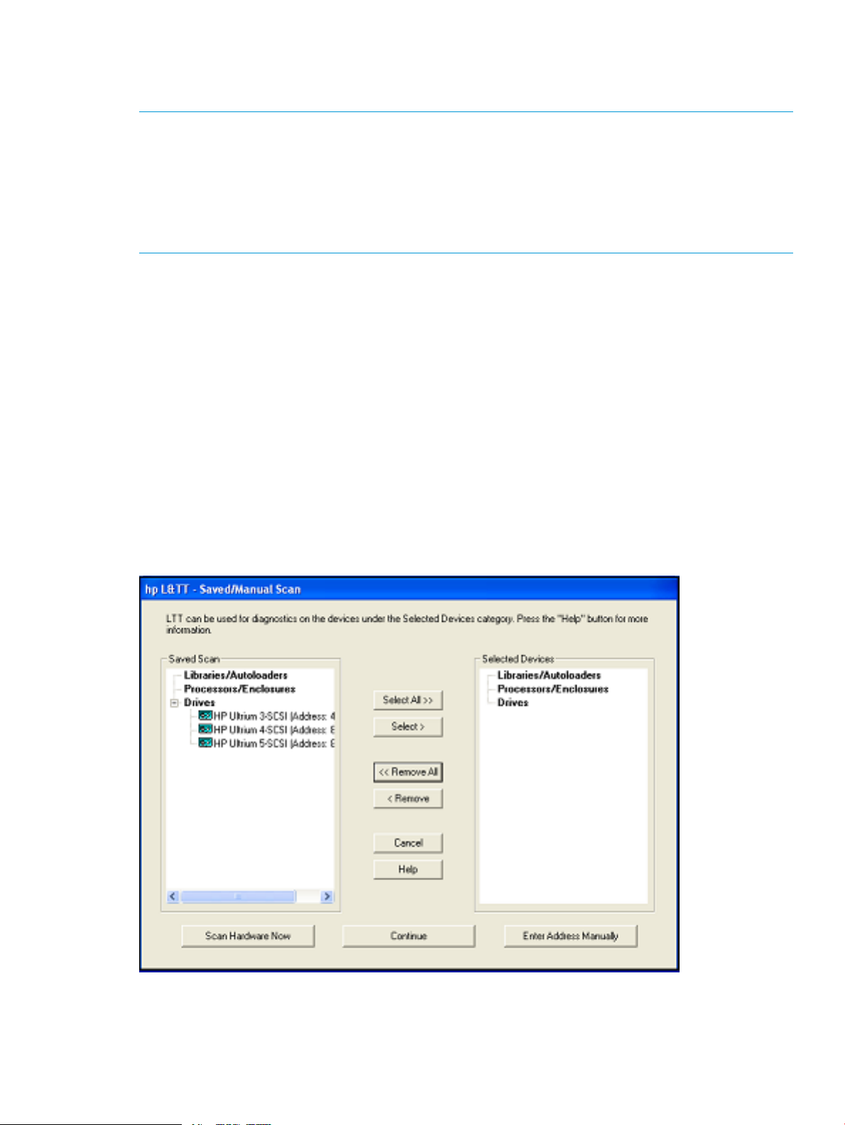
Saved/Manual scan
The left panel of the Saved/Manual Scan screen displays the devices detected in the last saved
scan. If this list is incomplete (for example, if new hardware has been added since the last scan),
click Scan Hardware Now to rescan the system for new devices. If you want to manually add a
device to the list of devices to be scanned without performing a full hardware scan, click Enter
Address Manually.
Use the Select All, Remove All, Select, and Remove buttons to select the devices. Selected devices
are displayed in the right panel of the screen. These devices are scanned and identified by L&TT.
Click Continue to perform the scan and proceed to the L&TT main screen. L&TT saves the list of
selected devices so the next time you start L&TT and display the Saved/Manual Scan screen. L&TT
displays all of the previously selected devices in the right panel as shown in Figure 3 (page 17).
Skipped devices will not be displayed in the device list on the L&TT main screen.
Figure 3 Saved/Manual Scan screen
Using the graphical user interface 17
Page 18

Additional device scan considerations
After the initial scan is complete and saved, future full system hardware scans become unnecessary
in most cases. You must perform a hardware scan after any of these actions have occurred
(Windows in NT Miniport I/O mode of operation):
• After the hardware configuration is changed.
• After power cycling more than one of the tape drives on the system.
• After updating firmware in more than one of the tape drives on the system.
To perform a hardware scan, exit and restart L&TT. On the Startup screen, select the Hardware
Scan option.
NOTE: If the Hardware Scan option is not selected, the Windows operating system might get
out of sync with the L&TT saved scan because Windows device rediscovery assigns new logical
device names to the devices.
Also, if you power cycle or update firmware in a device while using a saved scan, the device may
not be accessible until it is rediscovered by Windows. If you select the device before it is
rediscovered, L&TT generates an error. After Windows has rediscovered the device, the device
can be selected without causing an error.
If you are running in saved scan mode and want to rescan the bus for devices, clicking Rescan
button on the Scan tab of L&TT will not initiate a hardware scan. You must exit and restart L&TT,
and then choose the Hardware Scan option on the Startup screen to execute a hardware scan.
I/O mode
L&TT selects the I/O mode that is most appropriate for the system it is running on. However, this
initial screen allows for manual selection of the I/O mode in certain cases. L&TT currently operates
in the following I/O modes:
• NT Miniport —Uses an interface that is native to Windows NT 4.0, 2000, XP, and Windows
• ASPI—Uses an optional I/O programming interface that is available on all versions of
Server 2003. This is the preferred I/O mode on systems where it is available because it does
not require the installation of the ASPI interface. However, there are some limitations to the
Windows NT Miniport I/O mode related to using devices that are “claimed” by other
applications, or that are used with non-standard OS drivers. In those cases, selecting the ASPI
I/O mode can make a device accessible.
L&TT supports Microsoft Storport technology. Storport is a new storage driver model created
by Microsoft for Windows Server 2003 and future Windows® operating systems. Storport
offers a higher performance architecture and better Fibre Channel compatibility in Windows
systems. If Storport drivers are installed, L&TT automatically uses Storport when you select NT
Miniport.
Windows. This I/O mode can be used with any Windows operating system. It may require
the installation or update of additional OS components, possibly requiring a reboot of the
system during installation.
NOTE: ASPI is not officially supported by Windows Server 2003. However, in most cases,
it will function properly. If ASPI is installed with Windows Server 2003, L&TT can make use
of it if the ASPI I/O mode is selected. However, HP recommends that you to use the default
NT MiniPort I/O option with Windows Server 2003.
• Ethernet—Uses the Ethernet interface. After selecting this option, you can choose from the
available set of libraries (MSL G3, ESL G3, ESL-e, and EML-e).
18 Using L&TT on Windows
Page 19
Skip this dialog in the future
If this checkbox is selected when you click Continue, the Startup screen is not displayed on
subsequent uses of L&TT. The program will continue to use the settings that you selected the last
time the Startup screen was viewed.
To re-enable the Startup screen, select Preferences from the Options menu. Check the Display initial
dialog at startup option and restart L&TT.
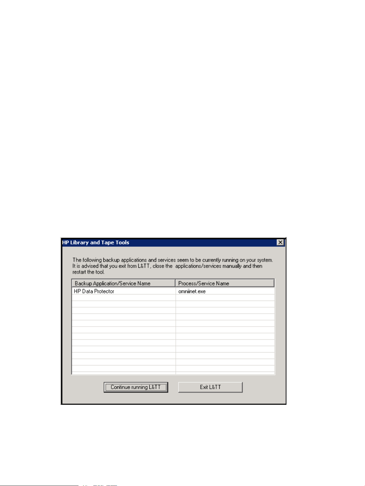
Check for backup applications and services
L&TT cannot access tape devices that are exclusively locked by another application. Select Check
for Backup Applications and Services and click Continue. L&TT displays a list of currently-running
backup applications and services. Based on this information, you can decide whether to stop the
backup application and service or continue running L&TT, knowing that it will not have access to
the tape devices in use, or exit L&TT. This option is enabled by default.
L&TT can detect if any of these backup or storage applications are running as shown in Figure 4
(page 19).
• Symantec Backup Exec
• VERITAS Netbackup
• EMC Networker
• CA-Arc Serve
• Data Protector Express
• HP Data Protector
Figure 4 List of Backup Applications/Service Name
Using the graphical user interface 19
Page 20
Application window layout
After the I/O mode is selected, click Continue on the Startup screen. The L&TT main screen is shown
as in Figure 5 (page 20). The main screen is divided into three sections:
• Taskbar
• Device list
• Device information
Figure 5 L&TT main screen
The three sections of the L&TT main screen are:
1. Taskbar—This section contains buttons that provide quick access to the main functions of L&TT
and to the online help system as shown in Figure 6 (page 20).
NOTE: Above the Taskbar is the Standard Windows menu bar that provides alternate
navigation to tool functions, as well as access to other features.
Figure 6 L&TT main screen buttons
2. Device list—This is a multi-function window that offers several options on the following tabs:
• Scan—This option either provides a summary status or detailed information (depending
on whether Show Details or Hide Details is selected) about the bus scanning
process. If a problem is encountered during the scan, this information may help in
20 Using L&TT on Windows
Page 21

determining the cause. When the scan completes successfully, the device list automatically
switches to the By Product tab.
The Scan tab allows you to rescan the bus. If any devices are hot-swapped or powered
on after the OS has booted, in most cases, the rescan feature can discover those devices
without rebooting the system.
CAUTION: Swapping SCSI devices, including either connecting and disconnecting
cables or terminators or both can hang or crash the system.
• By Product—This option lists all products connected to the system. The list is grouped
into the following four categories:
◦ Libraries and autoloaders
◦ Drives
◦ Enclosures and processors
◦ Other devices
The three number fields listed after the device represent the device address. Each field in
the address is separated by a period: the first field represents the HBA channel, the second
field represents the SCSI ID, and the third field represents the LUN.
NOTE: When using the Miniport I/O mode, the HBA channel field is shown as “A/B,”
where A is the channel and B is the subchannel.
• By Connection—This option lists all products connected to the system, grouped by the
HBA they are connected to. This makes it easier to see which devices are connected to
the same bus as the device in question, and helps in understanding the system I/O
performance issues.
• Instructions—This option contains brief instructions on how to use the selected screen.
This view can be disabled in the software preferences.
3. Device information window—All the main functions of the program are displayed in this
window. The content of this window depends on the device and the tool function selected.
Using the Device Information screen
When you select a product from the device list, the device information screen displays information
relevant to the device. The device list displays the instructions on the page (if the instructions
preference is enabled). Click Identity on the toolbar, if another tool function is currently active. The
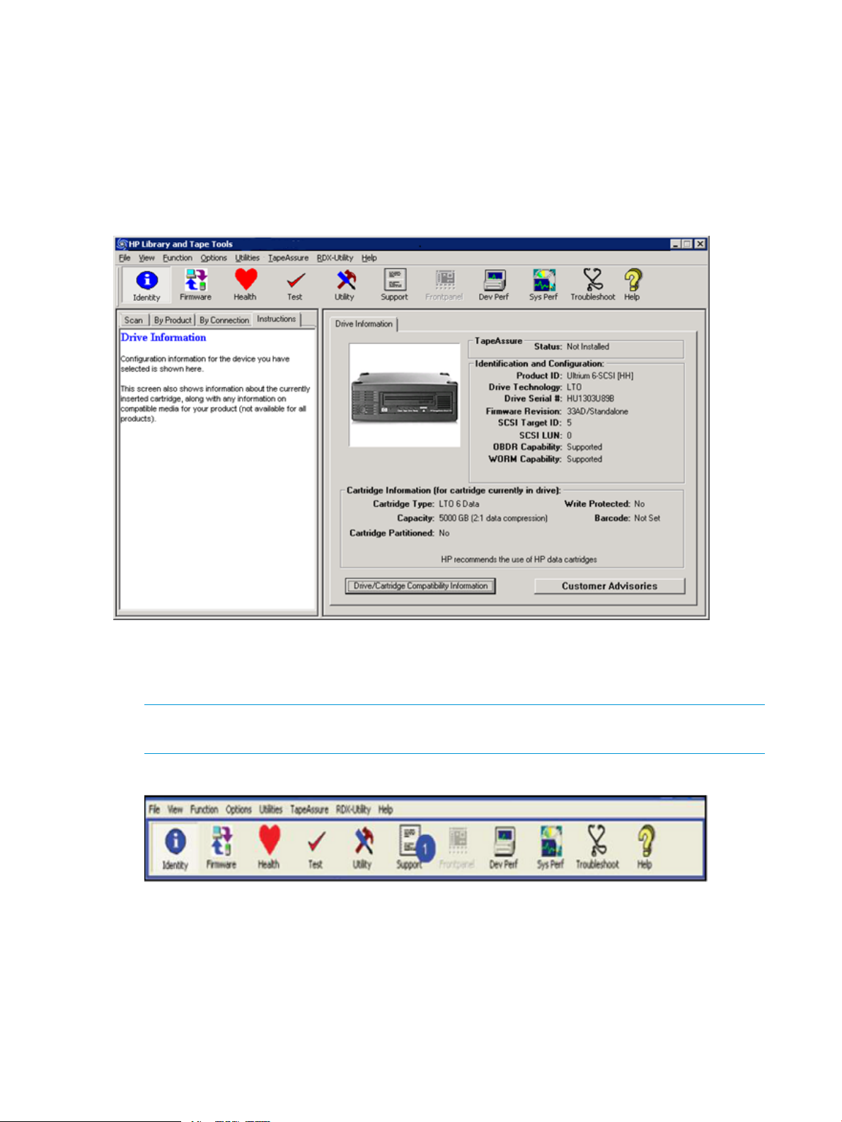
Device Information screen appears.
The Device Information screen provides an overview of the selected hardware device and its current
configuration and status.
Standalone devices
The Device Information screen, showing a standalone device, contains a single tab labeled Drive
Information. The screen has four main sections, as shown in Figure 7 (page 22).
Using the graphical user interface 21
Page 22
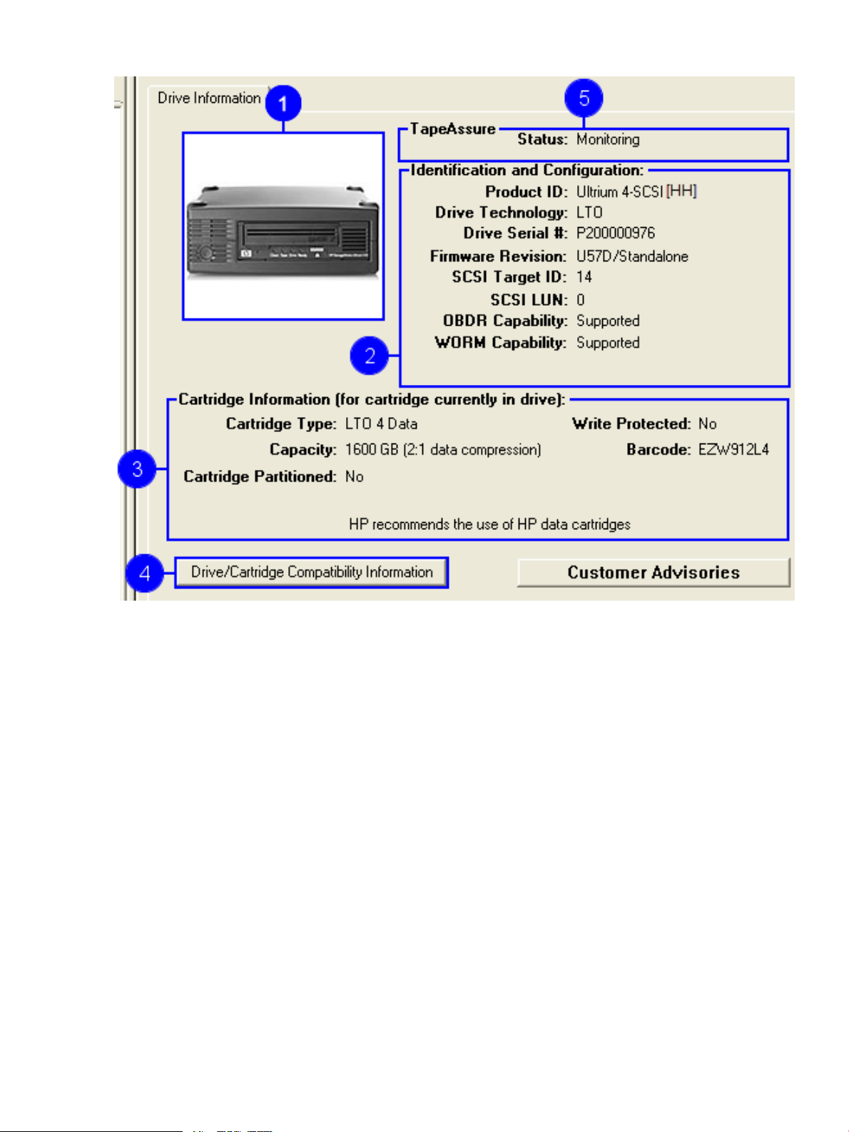
Figure 7 Device information screen
1. A visual representation of the selected product (the images are in grayscale).
2. Provides the following general information on the product:
• Product ID (Inquiry String)
• Drive Technology (DDS/DLT/SDLT/VS/LTO)
• Mech Serial # (Drive serial number)
• Firmware Revision
• SCSI Target ID
• SCSI LUN
• HH (half height) or FH (full height)
3. If a data cartridge is inserted in the drive when the identity tool is selected (or when the current
screen is refreshed), information regarding cartridge type, capacity, barcode, partitioning
status, and write protect status is shown. If the cartridge is formatted using LTFS, the information
is displayed with the cartridge type.
4. Click this button to display a list of media that is compatible with the product, as shown in
Figure 8 (page 23). The information provided for each type of media is:
• Cartridge characteristics.
• Capabilities of this drive to handle the cartridge.
• HP part number for the cartridge.
22 Using L&TT on Windows
Page 23
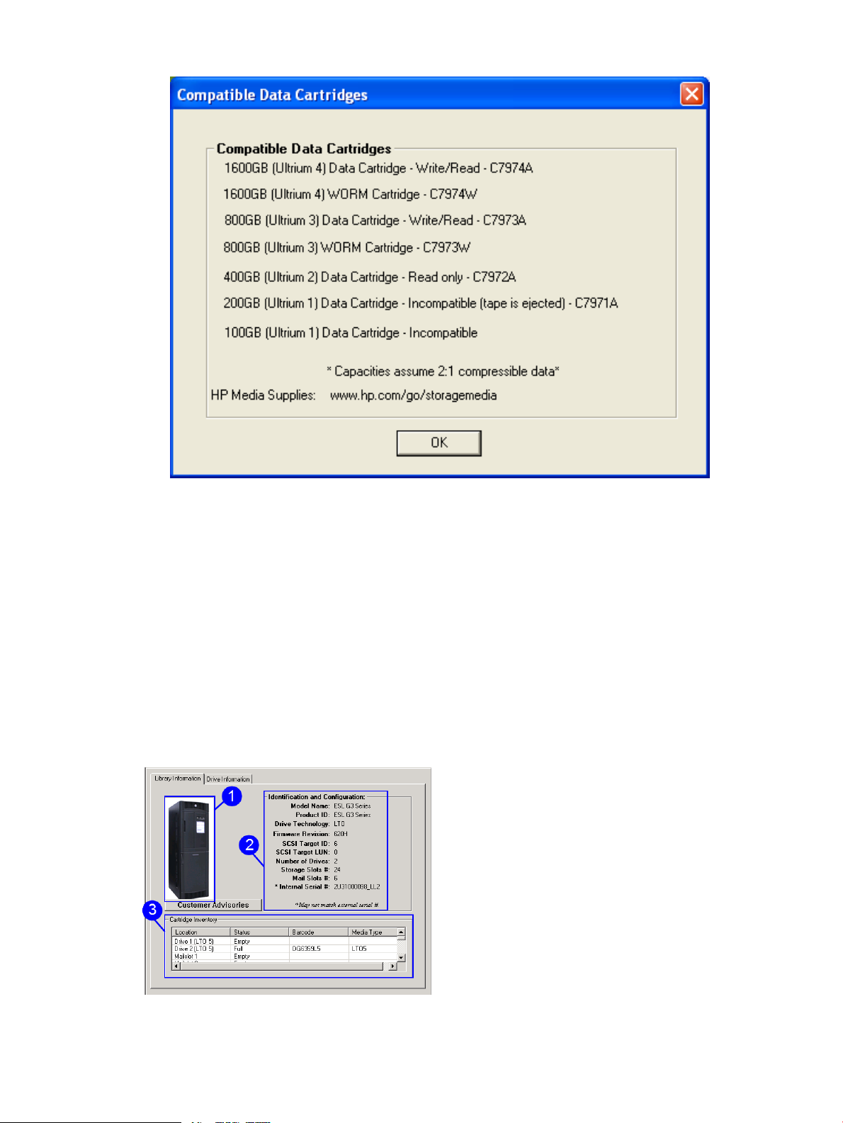
Figure 8 Compatible data cartridges screen
5. TapeAssure service status for the selected drive. TapeAssure is supported for LTO-3 and later
generation LTO tape drives.
6. Click this button to find any customer advisories for the product. When a recent advisory is
available, the button will have blue highlights, as shown in Figure 7 (page 22). For reliable
operation, HP recommends users to read product advisories.
Library and autoloader products
When a library or autoloader is selected in the device list, the Device Information screen displays
two tabs as shown in Figure 9 (page 23).
• Library Information
• Drive Information
Figure 9 Library information and drive information
Using the graphical user interface 23
Page 24
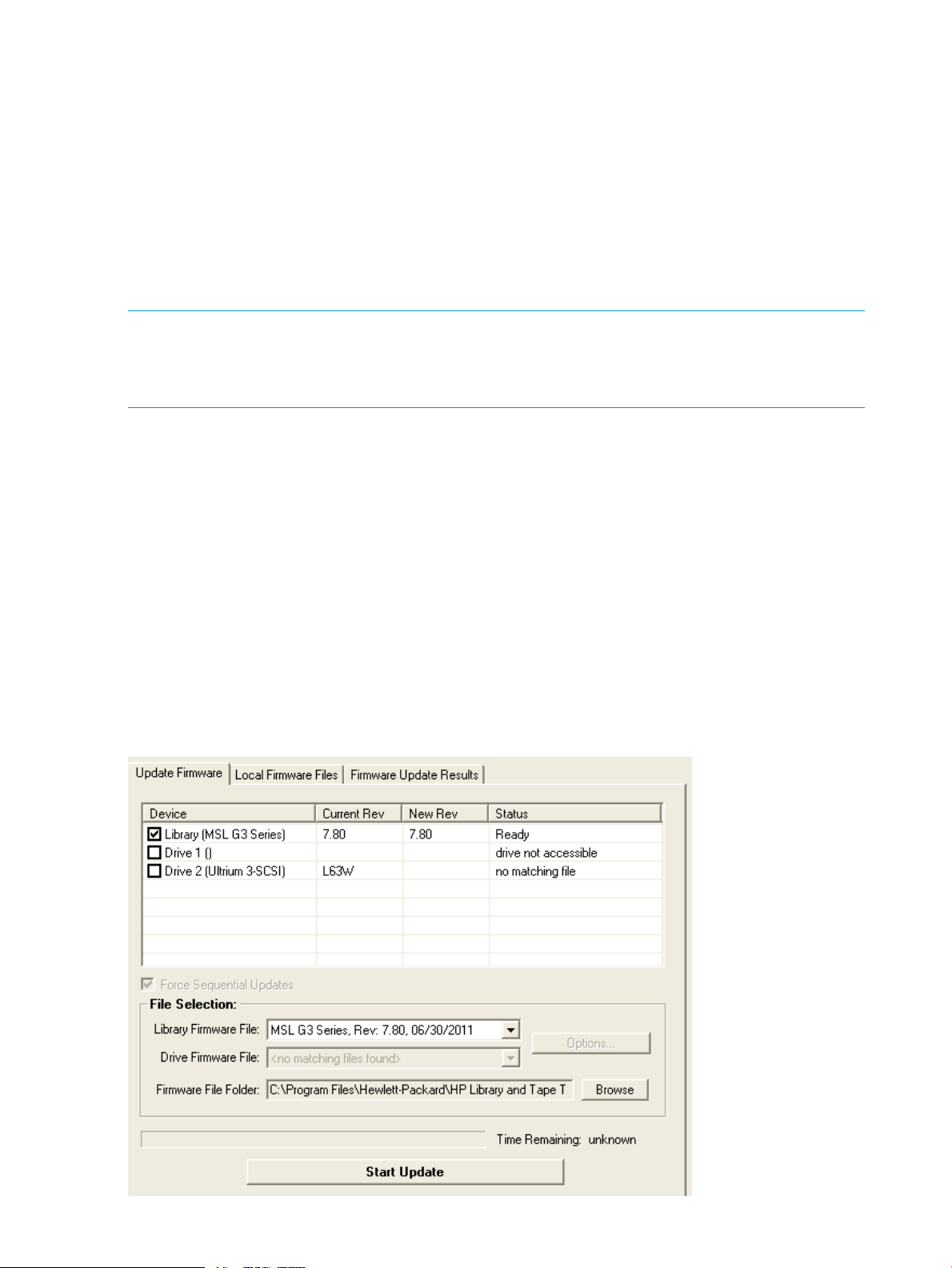
1. A visual representation of the selected product (the images are in grayscale).
2. As with a standalone drive, this area provides the relevant information on the selected library
product.
3. This provides a cartridge (media) inventory for all the drives and slots. The current status (full
or empty) of all the storage elements, bar code number (if bar code reading is available), and
media type are displayed here.
For more information on the drives within the library, select the Drive Information tab. This tab
displays a screen very similar to the one for standalone products, with the addition of the Selected
Drive menu.
All of the drives in the library are available in the Selected Drive menu. You can select and view
information for each drive using the menu.
NOTE: Selecting individual drives within a library from the By Product or By Connection device
list displays the drive as though it were a standalone product. The recommended method of
diagnosing embedded drives is to first select the library they belong to, and then select the specific
drive within each tool window.
Using the firmware management screen
The firmware management functionality of L&TT allows easy upgrade to the firmware of the storage
product and the connected devices. L&TT uses special firmware files that associate the firmware
with a particular product. This feature prevents the user from downloading the wrong image and
ensures that the downloaded firmware is the same as, or a newer revision of the current device
firmware.
In order to upgrade the firmware for the devices, follow the below steps:
1. Check the firmware versions.
2. Acquire the firmware files.
3. Upload firmware files to the devices.
To access the Firmware Management screen, select the devices you want to update in the device
list, then select the device listed on Update Firmware tab as shown in Figure 10 (page 24).
Figure 10 Firmware management screen
24 Using L&TT on Windows
Page 25

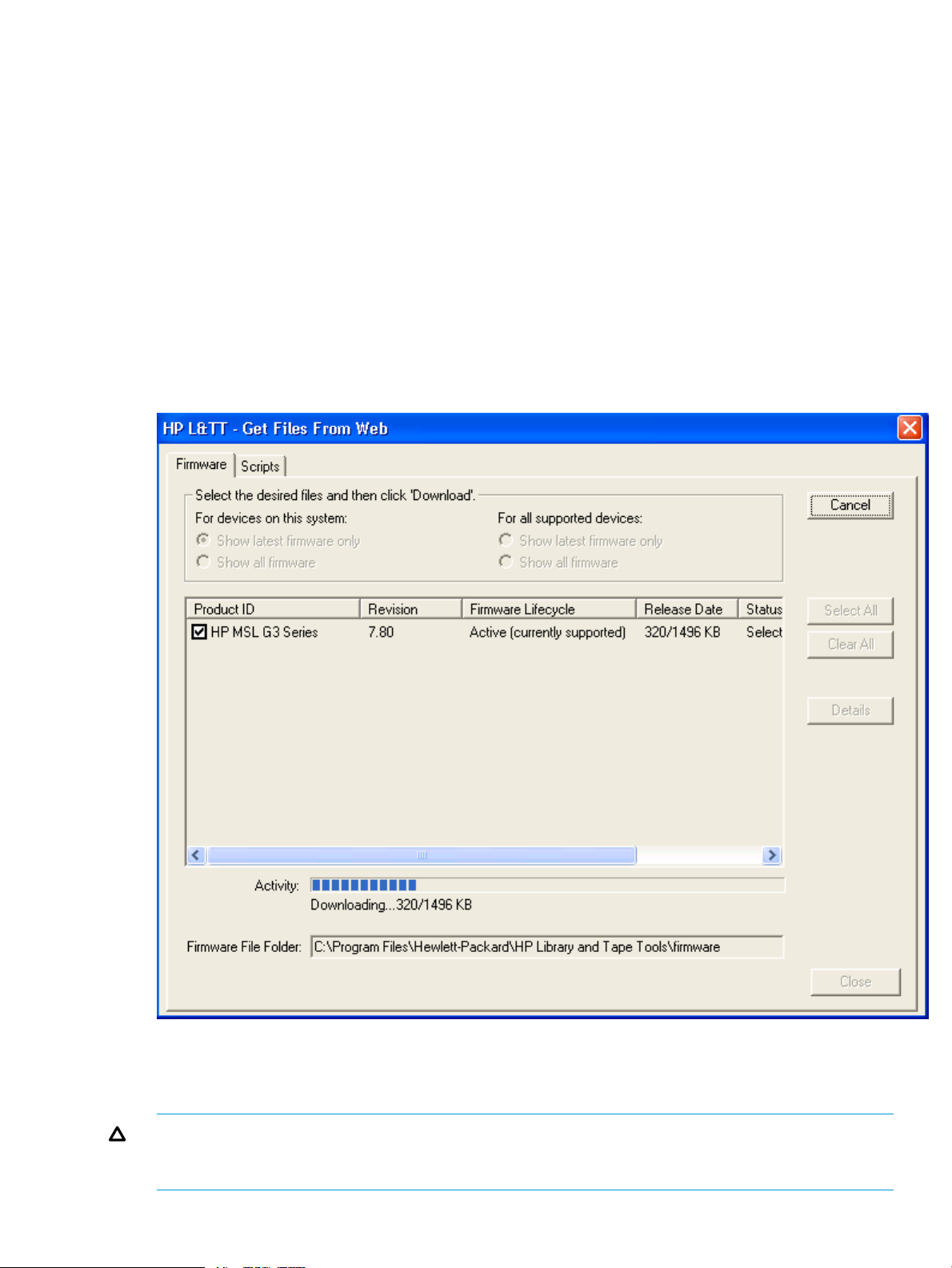
Get files from web functionality
The Windows version of L&TT offers comprehensive firmware management functionality that finds
and downloads firmware from the HP website. This functionality obtains the most up-to-date
information about all available firmware files directly from the HP website. It then compares this
data set against the list of devices connected to the system and the current firmware revisions
present in those devices. Depending on the selected filter options on the top of the screen, different
subsets of firmware files are presented. Firmware files that are needed to bring the connected
devices up to the latest firmware revisions are automatically selected.
You can access the Get Files from Web dialog box in two ways:
• Select Get Files from Web from the File menu.
• Click Get Firmware on the Firmware Update screen.
The Get Files from Web dialog box is displayed. Click Firmware (New Files Available) tab if it is
not already selected. The Activity bar shows progress during two phases:
• While L&TT is gathering and analyzing information about the available firmware files.
• While downloading the selected firmware files, the Activity bar will slide from the start to the
finish for each file downloaded.
Checking firmware versions
To verify the latest firmware revision for a device, or to learn about the changes between the current
revision and the latest revision, use the Get Files from Web feature of L&TT.
To access firmware revision and release note information from the L&TT application:
• In the L&TT main screen, click File > Get Files From Web, or click Firmware on the menu bar,
select the Local Firmware Files tab, and then click Get Firmware From Web. The Get Files From
Web window s.
• To view the latest firmware revisions for devices on your system, or for all devices, click
Firmware tab, and then select the appropriate option.
• To view release note information, click Product ID of the firmware file whose information you
want to view, and then click Details. The release notes are displayed in the File Details window.
To view the firmware release notes for the firmware files in the local firmware folder, in the
Local Firmware Files tab select one of the firmware files and click Release Notes.
Viewing firmware revision history
In addition to downloading firmware files, the Get Files from Web dialog box provides revision
history detail for firmware files. To view the firmware revision history of a device, select a Device
and click Details.
Managing firmware
• “Acquiring firmware files” (page 25)
• “Selecting and downloading updated firmware files” (page 26)
• “Uploading firmware to devices” (page 27)
• “Advanced options” (page 28)
• “Using test screen” (page 29)
Acquiring firmware files
L&TT firmware files are stored in the Firmware directory. This directory is a subdirectory of the HP
Library & Tape Tools installation directory. Before upgrading any firmware, you must first acquire
the firmware image file or files and copy them to the Firmware directory.
Managing firmware 25
Page 26

Firmware files can be obtained in three ways:
1. Select the device in the device listing and click Firmware on the main toolbar. On the Firmware
screen, click Local Files tab, and then click Get Files from Web button at the bottom of the tab.
The downloaded files are automatically placed in the Firmware directory.
2. From the L&TT menu, select Get Files From Web from the File menu. The software links to the
L&TT firmware FTP site and allows the selected firmware files to be copied to your system.
Downloaded files are automatically placed in the Firmware directory. This option is explained
in detail in the following section.
3. Go to “http://www.hp.com/support”, choose the product family, and click Software Updates
and Drivers. The latest firmware file is available in L&TT format. For some products (such as
standalone drives), firmware is available as a single file. For other products (such as tape
libraries), the firmware is available in a self-extracting bundle that includes library and drive
firmware.
CAUTION: Do not use the Get Files From Web functionality within L&TT without an internet
connection. This can lock the system until it has timed out in the operating system. This timeout
value is operating system-specific.
NOTE: If Check for Updates on Web is enabled in the tool preferences, L&TT automatically
informs the user when new firmware is available for any of the connected storage products. L&TT
performs this check each time it is started (but not more than once per 24-hour period).
Selecting and downloading updated firmware files
The Get Files from Web dialog box has four filter options:
• For devices on this system—The below options show firmware files matching devices that are
currently connected to the system.
◦ Show latest firmware only—This shows the most recent firmware revision for
each device.
◦ Show all firmware—This shows all firmware revisions for each of these firmware
files.
• For all supported devices—The below options show firmware files for all devices supported
by L&TT, even if not currently connected to the system.
◦ Show latest firmware only—This shows the most recent firmware revision for
each device.
◦ Show all firmware—This shows all firmware revisions for each of these firmware
files.
The entry for each firmware file includes the Firmware lifecycle that describes the support
status of the firmware file. The three states are:
• Active (currently supported)
• Inactive (obsolete and not supported)
• Controlled (Hotsite)
Select the appropriate option and verify the correct firmware files. To download the selected files,
click Download. The files are automatically downloaded to the current firmware directory on the
local system. You can use the firmware update functionality of L&TT to upload the latest firmware
to your devices.
26 Using L&TT on Windows
Page 27
Uploading firmware to devices
Before updating any firmware files, you must acquire the latest firmware files and ensure that they
are placed in the Firmware directory.
To upload firmware to a device:
1. Click the device to update in the device list.
2. Click Firmware on the main toolbar.
3. On the Update Firmware tab, select the device to update firmware. If firmware is currently
available for that device, it is shown in Firmware File in the File Selection section of the screen
as shown in Figure 11 (page 27).
4. Click Start Update at the bottom of the screen to begin the update.
Click OK in the Firmware Update status dialog. The Firmware Update Results tab is displayed,
showing a log of the firmware upload activity. Set the Current Detail Level to the appropriate level.
The default is Normal. If you want to clear the log, click Clear Log button.
Figure 11 Update firmware screen
On completion of firmware update, the Firmware Update status dialog box is displayed, explaining
what happens to the Windows plug-and-play implementation. It also explains how to make the
drive visible to L&TT and the Windows operating system, so that it will operate properly.
CAUTION: Make sure that no other programs attempt to access the device while the firmware
is being updated. Do not interrupt the firmware update. If the firmware update is interrupted, the
device may not operate and may require physical repair.
Managing firmware 27
Page 28
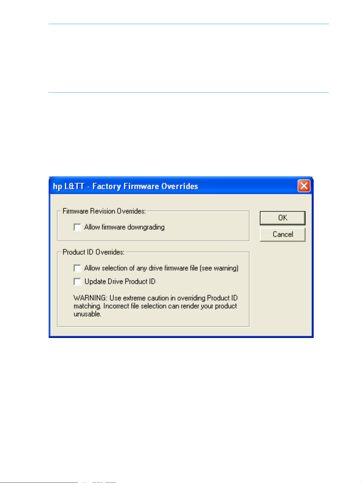
NOTE: With several products, after the firmware file is selected, a message is displayed to inform
the certain requirements such as important prerequisites for updating with the new firmware, or
noteworthy functional changes (such as a new LED sequence). Be sure to read any such messages
and take appropriate actions. If the device is either not visible to L&TT and operating system or
both after the firmware is updated successfully, follow the process indicated in the Firmware Update
window to ensure the updated device is fully visible and usable by the system. Make sure you
follow this entire procedure before calling HP customer support. In case the device is still not
accessible, call HP customer support for assistance.
Advanced options
It is sometimes necessary to disable L&TT safeguards to perform more advanced operations. These
operations (options) are only available after entering the necessary password. To obtain the
password, contact HP support. After you have entered the password, the Options button on the
Update Firmware tab becomes available. Click Options the Factory Firmware Overrides dialog
box appears as shown in Figure 12 (page 28) (this dialog box varies slightly between drives and
libraries).
Figure 12 Factory firmware overrides dialog box
The Factory Firmware Overrides dialog box appears with the following three options:
• Allow firmware downgrading—By default, L&TT does not show files with older revision levels
as selectable. On the Local Firmware Files tab, the comment field displays the message
“downgrade password required.” In most cases, you must use the latest firmware. However,
if software incompatibilities or other customer limitations require the use of older firmware
revisions, select the check box to downgrade to the older firmware revisions.
• Allow selection of any [drive or library] firmware file—This option allows mapping of the
device firmware to a product, irrespective of the device's product ID. There are few cases in
28 Using L&TT on Windows
Page 29
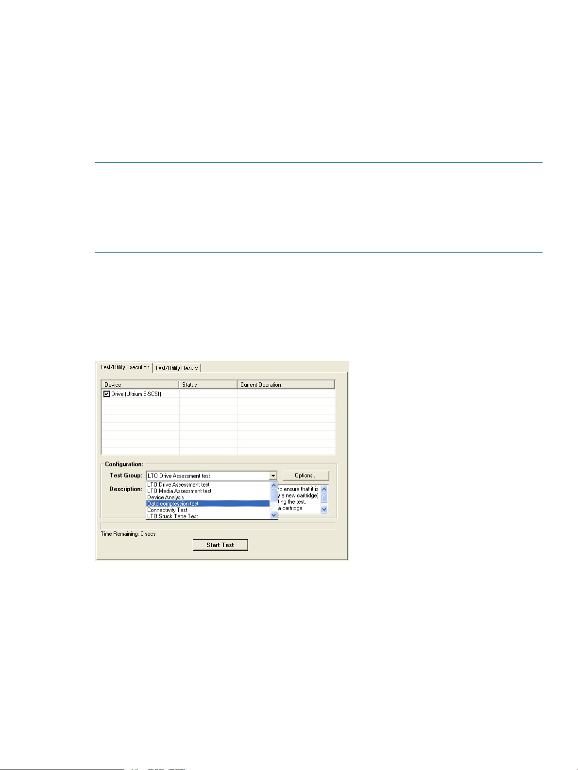
which the product ID does not match the desired firmware file (and the ID may also need to
be updated):
◦ When a library is being updated from one drive technology to another.
◦ when the device has a firmware revision string format that differs from that in the firmware
file, and the tool cannot determine whether it is newer or older. If incompatible firmware
is sent to a device, an error message is displayed.
• Update [Drive or Library] Product ID—This writes the product ID from the firmware file to the
drive.
NOTE: A number of products may not support updating the product ID, so use this feature only
when you know the device supports it. The most common use of this feature is for updating drive
technologies in optical libraries.
NOTE: After setting any of the advanced options, if firmware file selected for download is different
in any way from the firmware files needed by the library or tape drive, the Status column of the
Update Firmware tab will show a warning message.
Using test screen
L&TT provides several standard and advanced tests that can be used to check the performance of,
or to diagnose issues with storage hardware. To access the tests screen, click the device you want
to test in the device list, then click Tests on the main toolbar. The Test screen is displayed, as shown
in Figure 13 (page 29).
Figure 13 Test screen
Running tests and device-specific utilities
To select and run a test or device-specific utility manually:
1. In the device listing (the By Product or By Connection tab), click Device to test.
2. Click Test (to execute a test) or Utility (to run a utility) on the main toolbar. The test and utility
screen s with the Test/Utility Execution tab selected.
3. Click the checkbox to the left of the name of the devices to test. The Test Group menu lists all
the tests available for the selected device.
4. In the Test Group menu, select the test to perform. The Description text box describes the
selected test.
Managing firmware 29
Page 30
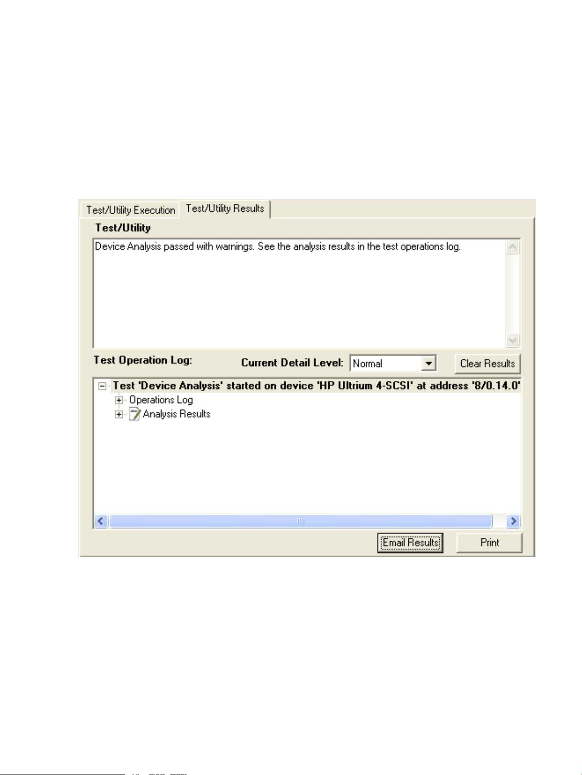
5. If any options are available for the selected test, the Options button is enabled. Click Options
button to review and set the desired options. When you click an option the description of the
option is shown. To return all of the options to their default values, click Defaults.
6. Click Start Test button to start the test.
Viewing results
When the test or utility is complete, L&TT shows preliminary results of the test. When you click OK
in the dialog, the test results are displayed in the Test/Utility Results tab. The Test/Utility box shows
the results of the test. A more detailed test operation log is displayed in the bottom section of the
screen. Click the “+” or “–” signs to expand or collapse a section of the report. Select an option
in Current Detail Level to display more or less information in the Test Operation Log.
Figure 14 Test/Utility results
To email the results to a support provider, click Email Results as shown in Figure 14 (page 30).
Fill in the information fields in the Email Test Results dialog and click Send.
30 Using L&TT on Windows
Page 31

Figure 15 Email Test/Utility results
Aborting a test
The selected L&TT tests can be stopped before they complete. Check the test description to see
whether the test can be terminated.
NOTE: Some tests can take several minutes to stop after they are terminated.
Managing firmware 31
Page 32

For tests that can be terminated, the Start Test button changes to Abort Test as shown in Figure 16
(page 32).
Figure 16 Aborting Test button
Click Abort Test. The L&TT will attempt to abort the test, which can take 10 – 20 seconds or more.
Once the Abort button is clicked, the button is greyed out and cannot be clicked again.
NOTE:
• If multiple drives are selected, the tests will run in parallel.
• Some tests can take several minutes to stop after they are aborted.
Using the utility screen
L&TT provides several basic utilities to perform functions on a storage device or media in the device.
To access the utilities screen, select the device you want to test in the device list and click Utility
on the main toolbar as shown in Figure 17 (page 33).
32 Using L&TT on Windows
Page 33

Figure 17 Utility screen
For detailed information about the utilities screen, as well as information about how to run the
utilities, see “Tests”.
Using the support ticket screen
A prime feature of L&TT is the ability to generate reports and support tickets. L&TT can automatically
generate a support ticket based on information that the program determines about the system. In
the event of a hardware problem, a report or support ticket can provide vital information to help
diagnose and resolve the problem. The information in this support ticket can then be used to
diagnose storage hardware issues. L&TT automatically emails the support ticket to the HP help
desk. The help desk technician assist in resolving the issues.
The reports and support tickets are generated in two ways:
• Generate reports and support tickets from the support screen. The support screen gives you
the option of viewing, saving, or emailing the report or support ticket. To access the support
screen:
1. Select a device in the device list (By product or by connection tab).
2. Click Support on the main toolbar.
• Click Health to generate reports. This is the preferred method for quickly generating and
displaying a report.
1. Select a device in the device list (By product or by connection tab).
2. Click Health on the main toolbar. The report is generated and automatically displayed
in the report viewer using the Normal detail level as shown in Figure 18 (page 34).
Managing firmware 33
Page 34

Figure 18 Support ticket generation screen
NOTE: In addition to the above options, the bottom section of the support screen provides
resources for finding support on the web. Click any of the buttons in the Support Resources on the
web section of the screen to a browser window and view the corresponding website.
The following steps allow user to extract and send the support ticket by email:
• “Extracting a support ticket” (page 34)
• “Saving a report or support ticket” (page 34)
• “Viewing a report or support ticket” (page 34)
• “Sending a report or support ticket by email” (page 35)
Extracting a support ticket
Click Extract Device Data to generate the report or support ticket.
After extracting the device data for the first time, the Extract Device Data button text changes to
Refresh Device Data. You should refresh the device data whenever a change is made to the device
that can affect the support ticket, such as running a test or loading/unloading a cartridge.
Saving a report or support ticket
Click Save Support Ticket to save the report or support ticket.
When you save a support ticket, L&TT generates a single, tarred, zipped support ticket with the.lzt
file type in the logs directory. The support ticket is named st_<date>_<time>_<serial
number>.lzt by default. The support ticket is a compressed, tarred file containing the master
ticket file, sticket_header<time>.ltt, and one or more VidPid_UID.ltd data files for
each device.
Viewing a report or support ticket
Click View Support Ticket to view the report or support ticket in the report viewer. The report or
support ticket can be saved or sent by email.
After a report or support ticket is generated, it is displayed in the report viewer. Click the “+” and
“–” signs to expand and collapse sections of the support ticket. Use the standard navigation keys
34 Using L&TT on Windows
Page 35

(Home, End, Page Up, Page Down, and the arrow keys), the Windows scroll bars, and the mouse
to navigate through the document.
To print the report or support ticket, select File > Print from the menu bar within the report viewer.
To view the saved support ticket, the .lzt file using Windows Explorer, or use the Load command
on the L&TT File menu.
NOTE: To view or email the individual files, rename the .lzt file so it has a .tar file extension
and use WinZip to extract the files to a single directory. The master ticket file will have a .ltt.lzo
extension, and the data files will have.ltd.lzoextensions. You can the master ticket file with
Windows Explorer or with the Load command on the L&TT File menu.
Sending a report or support ticket by email
Click Send Support Ticket by Email to send the report or support ticket immediately by an email to
an HP support center (or other destination) as shown in Figure 19 (page 36).
Managing firmware 35
Page 36

Figure 19 Email Support Ticket dialog box
Prerequisites
Before L&TT can email a report or support ticket, you must either have a MAPIcompliant email
program (such as Microsoft Outlook or Outlook Express), or you must set up an email account
through the Windows Control Panel or Internet Explorer. For more information about setting up an
email account, see “How do I configure e-mail to send support tickets?” (page 155).
36 Using L&TT on Windows
Page 37

From the Support screen, click Send Support Ticket by Email to send the report or support ticket by
email to an HP support center (or other destination). Clicking this button s a form that allows you
to provide all the necessary information. Complete the form and click Send.
NOTE: Using this option does not save a copy of the support ticket locally, so you are advised
to click Save Support Ticket to save a copy for future reference.
In addition to the above options, the bottom section of the support screen provides resources for
finding support on the web. Click any of the buttons in the Support Resources on the web section
of the screen to a browser window and view the corresponding website.
The Email Support Ticket dialog box is divided into three steps:
1. Indicate whether this is a new support request or an existing case.
• If this is a new support request, select Send to support provider to request support by
email. Enter the product number and product serial number in the appropriate fields.
• If this is an ongoing support case, select Send to support provider in reference to an case
and enter the case reference number in the appropriate field.
2. Enter the destination email address. Use the drop-down box to select from a list of HP support
providers, or enter the email address manually.
NOTE: Customer support personnel typically provides an email address to the users who
email a support ticket as a result of a support call request. In this case, the user must enter the
email address exactly as provided by the support person.
3. Specify the following additional information:
• Contact information—Enter your company name, contact name, contact phone, and
contact email address.
• Attach result Log—Attach the support ticket to the email for analysis by HP service
personnel.
• Attach additional event Log (only if requested)—Send the event log if requested by HP
service personnel.
• Problem description—Enter a detailed description of the problem.
When you have completed the form, click Send.
NOTE: L&TT defaults to 10 MB for maximum size for any email. If your email setup will not permit
email files as large as 10 MB, click L&TT Options > Preferences, click the check box for maximum
email size, and then enter a smaller number. If you attempt to email a support ticket using L&TT
that is larger than the maximum email size, L&TT will not send an email. In this case, you can save
the .lzt support to your disk. Rename the file to have a .tar file extension, and then use WinZip
to expand the support ticket into a single .ltt.lzo file and one or more .ltd.lzo files. You
can email these files individually.
When you save or email a support ticket, L&TT generates a single, compressed support ticket file.
The support ticket includes the master support ticket file,sticket_header<time>.ltt, and one
or more VidPid_UID.ltd data files.
If the report format is not yet available for the device selected in step 1, the Health button will be
grayed out. In this case, use the support screen to generate a support ticket.
Reports and support tickets are generated from the support screen. If the report format is available
for the selected device, a report will be generated. Otherwise, a support ticket will be generated.
For legacy 3.x large libraries, including SureStore 2/20, SureStore 4/40, SureStore 6/60,
SureStore 6/140, SureStore 10/100, SureStore 1/9, and the MSL5000 and MSL6000 series
libraries, the tarred support ticket contains a single compressed .dat file.
Managing firmware 37
Page 38

3 Using L&TT on non-Windows systems
• “Installation” (page 38)
• “Using the command screen interface (CSI)” (page 41)
• “Managing firmware” (page 47)
• “Running the tests (CSI)” (page 50)
• “Using reports and support tickets” (page 54)
Installation
• “Installing L&TT for Linux” (page 38)
• “Installing L&TT for HP-UX” (page 39)
• “Installing L&TT for HP VMS” (page 40)
• “Installing L&TT for Solaris” (page 40)
• “Installing L&TT for Mac” (page 41)
Installing L&TT for Linux
Linux installation prerequisities
Software dependencies/prerequisites
Device must be recognized by proc/SCSI subsystem.•
• Device drivers for the connected tape devices/libraries
or default device driver must be present.
• To install L&TT, you must first uninstall any previous
versions.
Unistalling previous versions
Before installing L&TT on Linux, you must first uninstall any previous versions. To determine if L&TT
is already installed, use the following command:
rpm -qa | grep ltt
To remove a previous version of L&TT, use the following command:
rpm -e ltt
38 Using L&TT on non-Windows systems
Page 39

Installing L&TT for HP-UX
HP-UX installation prerequisites
Software dependencies/prerequisites
Devices do not need to be claimed by the operating
•
system with ioscan for L&TT to access them.
• The sctl driver must be installed for L&TT to access the
device you want to test. L&TT builds its own
pass-through SCSI device files using the sctl driver, so
that driver must be installed; however, L&TT does not
need the operating system to list any of the devices as
"CLAIMED." They may be listed that way (if the
appropriate driver is installed), but they don't need to
be for L&TT to fully access them (beginning with L&TT
v3.3).
• Devices must NOT be listed as "NO HARDWARE" in
ioscan. If the device you want to test with L&TT is listed
as "NO HARDWARE" in ioscan, the communication
path between the host and the device is not working
and must be fixed before L&TT will be able to
communicate with the device.
Installation procedure for HP-UX and Linux
To install L&TT for HP-UX and Linux:
1. Log in as root.
2. Navigate to the temporary directory: cd /tmp
3. Download or copy the L&TT tar file, hp_ltt<xx>.tar (where <xx> is the version number)
to this directory. If you are copying the file from a different location, enter the following
(substitute the directory in which the file currently resides for<directory name>):cp /
<directory name>/hp_ltt<xx>.tar /tmp
4. Un-tar the L&TT tar file: tar -xvf hp_ltt<xx>.tar
5. Run the install script in the /tmp directory: ./install_hpltt
NOTE: For Linux, the L&TT installer verifies that the operating system you are installing on
is supported. If the Linux distribution or release is unsupported, the install script displays a
message indicating an installation failure and lists the supported operating systems.
6. After the software is successfully installed, enter the following commands to remove the /tmp/
ltt directory and its contents:
cd /tmp
rm -rf ltt
rm -rf install_hpltt
Installation 39
Page 40

Installing L&TT for HP VMS
HP VMS installation prerequisites
Software dependencies/prerequisites L&TT requires the following patches or higher to run
Unistalling previous versions
To determine whether L&TT is already installed on the system, use the following command:
$ Product show product ltt
To remove a previous version of L&TT, use the following command:
$ product remove ltt
Installation procedure for HP VMS
successfully:
• V7.3–2 Alpha
VMS732_FIBRE_SCSI-V0800VMS732_UPDATE-V0500
• V8.2 Alpha VMS82A_FIBRE_SCSI-V0100
VMS82A_UPDATE-V0200
• V8.2 Itanium VMS821_FIBRE_SCSI-V0100
VMS821_UPDATE-V0200
NOTE: L&TT is supported from VMS v7.3-2 onwards and is supported on both ODS-3 and ODS-5
file systems.
1. Download or copy the L&TT .zipexe file to a temporary directory.
2. Navigate to the directory you copied the install file to and enter the following commands to
install L&TT:
$ run hp-axpvms-ltt-v<xx>-1.zipexe (where <xx> is the version number) (alpha
platforms) $ product install ltt. The installation procedure creates the directory structure
opt.ltt in sys$sysdevice:[vms$common] and installs all the required files for L&TT.
Passing an alternate installation location via the /destination parameter will override the
default installation location, allowing installation on a non-system disk. $ product install
ltt /destination=<yyy> (where <yyy> is the preferred installation directory). To run
L&TT, use: $ @sys$startup:ltt$startup.com
Installing L&TT for Solaris
Solaris installation prerequisites
• The device must be shown in the cfgadm –al and prtconf –v command output.
• The device driver for connected tape drives and libraries or the default device driver must be
present.
Installation and uninstallation
To install the L&TT package:
1. Login as root.
2. Navigate to the temporary directory:
cd /tmp
40 Using L&TT on non-Windows systems
Page 41

3. Download or copy the L&TT tar file, hp_ltt<xx>.tar (where <xx> is the version number)
to this directory.
If you are copying the file from a different directory, enter the following command, substituting
the directory in which the file currently resides for <directory name>:
cp /<directory name>/hp_ltt<xx>.tar /tmp
4. Un-tar the L&TT tar file:
tar –xvf hp_ltt<xx>.tar
5. Run the installation script in the /tmp directory:
./install_hpltt
6. After the software is successfully installed, enter the following commands to remove the
temporary files from the installation process:
cd /tmp
rm –rf install_hpltt
rm –rf HPLTT<xx> (where <xx> is the version number)
To determine whether L&TT is already installed on the system, use the following command:
/usr/bin/pkginfo | grep LTT
To remove a previous version of L&TT, use the following command:
/usr/sbin/pkgrm HPLTT<xx> (where <xx> is the version number)
Installing L&TT for Mac
Mac installation prerequisites
Install time (typical) Less than 4 minutes
Reboot requirements None
Software prerequisites Mac OS 10.4 or higher
Installation and uninstallation
To install L&TT on Mac:
1. Log in to the Mac GUI using root or full system privileges.
2. Download or copy the install file to a temporary location. The install file is
hpltt_<xx>_mac.dmg (where <xx> is the version number).
3. Double-click the downloaded file. This action will mount the image.
4. Double-click the hp_ltt<xx>.mpkg icon.
5. Follow the screen instructions.
6. On completion, click Finish.
To remove L&TT from Mac:
• Remove the directory /usr/local/HP/LTT.
Using the command screen interface (CSI)
• “Starting L&TT” (page 42)
• “Navigating the screens ” (page 42)
• “Using the scan mode selection screen” (page 43)
• “Using the saved and manual scan screen” (page 44)
• “Using the device information screen ” (page 45)
Using the command screen interface (CSI) 41
Page 42

Starting L&TT
To start L&TT:
• For HP-UX (pre-11i v3), Tru64, and Linux:
Log on as root and execute the following commands:
cd /opt/ltt
./hp_ltt
• For HP-UX 11i v3:
HP-UX 11i v3 provides a new agile addressing format, which can be seen by executing
ioscan -fN and supports both persistent (new) and legacy Device Special Files (DSFs). Start
L&TT with the -N option to use the new agile addressing format.
Log on as root and execute the following commands:
cd /opt/ltt
For the agile addressing format and persistent DSFs: ./hp_ltt -N
For the legacy addressing format and legacy DSFs: ./hp_ltt
• For HP VMS:
Log on as system or an ALL privileged user and execute the command
@LTT$ROOT:[000000]start_ltt.com
• For Mac OS:
Bring up the terminal. Change the working directory to /usr/local/HP/LTT and initialize
L&TT by running the command ./hp_ltt.
Alternatively running the command hp_ltt would also initialize L&TT from any working
directory.
Navigating the screens
• The top line of each screen displays the current screen name in hierarchical format.
• Each level of screens is separated by the “>” character.
• On each screen, some of the available commands take you to a lower level in the hierarchy.
To move back to the previous level, use the up command.
• To exit L&TT, use the exit command.
• On most of the screens, entering a blank command (pressing Enter without typing any other
text) displays a Command Help screen. This screen contains a list of valid commands that can
be executed on the screen from which the Command Help screen was accessed.
• You can enter a command directly from the Command Help screen. To do this, type either the
number of the command or the name of the command and press Enter. Entering the number
of the command only works on the Command Help screen. From any other screen, you must
type the full name of the command. To exit the Command Help screen, enter a blank command
(press Enter).
• Some commands require an argument. For example, the select command requires a number
that corresponds to the device you want to select in the device list. To select the first device
in the list, the syntax is: select 1
• If you enter a command with an invalid or missing argument, an error message is displayed.
The Command Help screen is displayed, as shown in Figure 20 (page 43).
42 Using L&TT on non-Windows systems
Page 43

Figure 20 Command Help screen
Using the scan mode selection screen
When the CSI version of L&TT is started, the Scan Mode Selection screen is displayed, as shown
in Figure 21 (page 43).
Figure 21 Scan Mode selection screen
Using the command screen interface (CSI) 43
Page 44

When L&TT starts, it performs a device scan to identify all the devices connected to the computer,
either directly or through a SAN. In large SAN environments, this scan can take a long time.
The first time L&TT is run, it must perform a full hardware scan (Hardware Scan option). After
that is done, the results of the scan are automatically saved so that the next time L&TT is started,
the Saved/Manual Scan option can be used. If the Saved/Manual Scan option is selected
before a hardware scan is done, the list of available devices will be empty.
If you select Saved/Manual Scan, the Saved/Manual Scan screen is displayed, as shown in
Figure 22 (page 44) .
Figure 22 Saved/Manual scan screen
To have L&TT rescan the system for new hardware devices, use the rescan command.
Using the saved and manual scan screen
Use the Saved/Manual Scan screen to select the devices that you want L&TT to scan and identify.
This can save time in a large SAN environment if you are using L&TT to test a single device.
Unselected devices are not scanned and displayed in the device list on the L&TT Main screen.
The following command options are available:
• select—The indicated device or devices are scanned.
• selectAll—All devices are scanned.
• clear—The indicated device or devices are not scanned.
• unselectAll—Clears all devices. No devices are scanned.
• enterHWAddrManual—Manually enter the hardware address of a device to be scanned.
• hardwarescan—Performs a full hardware scan. Use this option to update the list of available
devices on the Saved/Manual Scan screen.
• continue—Starts the indicated scan and proceeds to the main screen.
• up—Exits the current command level.
• exit—Exits L&TT.
When the scan is complete, the Main screen is displayed, as shown in Figure 23 (page 45).
44 Using L&TT on non-Windows systems
Page 45

Figure 23 CSI Main screen
Using the device information screen
When you first select a product from the Main screen, the device information screen appears,
showing information relevant to the device.
The main purpose of the device information screen is to provide an overview of the configuration
and status of the selected hardware device.
From the Main screen, type the following command to access the device information screen:
select <n> (where <n> is the number of the device to be examined)
NOTE: Alternatively, you can omit the select command and enter only the device number.
Standalone devices
The following general information is displayed:
• Product ID (inquiry string)
• Drive technology
• Mech. serial # (drive serial number)
• Firmware revision
• SCSI target ID
• SCSI LUN
• OBDR capability (if present)
If a data cartridge was inserted in the drive when the device information screen was displayed,
information regarding cartridge type, capacity, and write-protect status is shown.
To see a list of compatible media that can be used with this device, use the cartridge command.
The device information screen for a standalone device is displayed, as shown in Figure 24
(page 46).
Using the command screen interface (CSI) 45
Page 46

Figure 24 Device information screen for a standalone device
Library and autoloader products
From the device information screen for a library device, use the cartridge command to display
the slot inventory of the library. The cartridge command shows which slots and drives currently
have cartridges loaded, and the cartridge bar code if available and applicable.
46 Using L&TT on non-Windows systems
Page 47

NOTE: Selecting individual drives within a library from the device list displays the drive as though
it were a standalone product. Embedded drives are best diagnosed by selecting the library they
belong to, and then selecting the specific drive within each tool window.
Figure 25 Device information screen for a library
Managing firmware
The firmware management functionality of L&TT provides a convenient way to easily upgrade the
firmware of connected devices. Library firmware and firmware of drives within the libraries can
be upgraded as well.
L&TT uses special firmware files that associate the firmware with a particular product. This feature
prevents the user from downloading the wrong image and ensures that the downloaded firmware
is the same as, or a newer revision of, the current device firmware.
CAUTION: Do not use L&TT to update firmware on a tape library or devices within a tape library
that is managed with HP StorageWorks Command View for Tape Libraries Software (Command
View TL). Firmware update operations for these devices must be performed using Command View
TL, as documented in the HP StorageWorks Interface Manager and Command View for Tape
Libraries Software user guide. If L&TT is used to update firmware on a managed library, the
management station will be out of sync with the actual firmware revision number and will report
a firmware mismatch. Furthermore, if you attempt to use L&TT to update firmware on a partitioned
library, L&TT reports an invalid command error.
To access firmware revision and release note information from the L&TT application (HP-UX and
Linux) follow the steps:
NOTE: The download function is not supported with VMS.
Managing firmware 47
Page 48

1. On the L&TT main screen, enter Download. A required file from the HP FTP site is downloaded,
and the Download Tool screen is displayed. The status area at the bottom of the screen displays
the progress of the download.
2. In the Download Tool area, enter 5 at the command prompt. The Selector screen displays the
various firmware files. Review the list and note the latest firmware revision for your product.
3. To review release note information, enter the number of the file whose release note information
you want to view. Use the ^U or ^D commands to page up or down through the screens to
find the desired product and firmware file. Not all firmware files have release note information
available.
Accessing details for local firmware files
To view firmware details, use the localfrmlist command, which will list the firmware files in
the local firmware directory.
To view the details of a firmware file, use the details command with the number of the firmware
file from the Local firmware list. For example details 2, will list the details for the DAT160
firmware file in Figure 26 (page 48).
Figure 26 Local firmware list produced by the localfrmlist command
Acquiring firmware files
L&TT firmware files are stored in the firmware directory, which is a subdirectory of the HP Library
& Tape Tools installation directory. Before upgrading any firmware, you must first acquire the
firmware image file or files and copy them to the firmware directory.
To download the latest firmware files:
1. Go to http://www.hp.com/support, choose your region, and then select storage for the
product category.
2. Select the product family, and then the particular product.
3. In the I would like to box, click download drivers and software.
48 Using L&TT on non-Windows systems
Page 49

4. Select the product and operating system, and then click the Download button in the firmware
section. The download file may be a single file (standalone drives) or a self-extracting bundle
that includes both automation and standalone drive firmware.
5. Download the file or files to the firmware directory. If it is a self-extracting bundle, extract
the contents to the firmware directory.
Using the get files from web functionality
NOTE: Downloading firmware files from the Web using the L&TT application is not supported
with NetWare, Mac, VMS, or Tru64 UNIX.
The CSI version (HP-UX and Linux) of L&TT can also find and download firmware from the HP
website. This functionality obtains the most up-to-date information about all available firmware files
directly from the HP website. It then compares this data set against the list of devices connected
to the system and the current firmware revisions present in those devices.
To use the Get files from web functionality:
1. From the Main screen, enter the download command. The Download Tool screen displays a
list of download options.
2. Enter the number of the desired option. If a download option is selected, the Selector screen
displays a list of available firmware files to download.
3. Enter the number of the desired firmware file to download. The file is downloaded to the
firmware directory.
Uploading firmware to devices
To upload firmware to one or more devices:
1. From the Main screen, type the number corresponding to the device to be updated and press
Enter to display the device information screen.
2. From the Device Information screen, enter the firmware command to display the Firmware
Update screen. Devices that are available for update are listed on this screen.
3. Type the corresponding number of the device you want to update and press Enter to mark the
device selected. If there are multiple devices, repeat this step for each device that you want
to update.
4. When all the required devices are selected, enter the start command to begin the update
process.
In L&TT 4.3 and later releases on Linux and HP-UX, if a library is selected along with one or more
of its tape drives, L&TT will upload firmware to the library first and then to all of the selected tape
drives in parallel. The firmware is only uploaded to the drives if the firmware upload to the library
was successful. If multiple tape drives are selected without their library, the firmware is uploaded
in parallel to all of the selected drives.
In L&TT 4.2 and earlier releases, and in L&TT 4.3 on operating systems other than Linux and HP-UX,
if multiple devices are selected, the firmware is uploaded sequentially on each of the devices.
Once the firmware upload is complete, a dialog box appears with the result of the firmware upload.
When you click OK, the Firmware Update Viewer is displayed, showing the log of the firmware
update.
CAUTION: Make sure that no other programs attempt to access the device while the firmware
is being updated. Do not interrupt the firmware update. If the firmware update is interrupted, the
device may not operate and may require physical repair.
L&TT creates a log of all firmware update activity. To view this log, enter the review command
from the Firmware Update screen.
Managing firmware 49
Page 50

Advanced options
Sometimes it is necessary to disable L&TT safeguards to perform more advanced operations. These
operations (options) are only available after you enter the necessary password. To obtain this
password, contact HP support. To view the Options screen, from the Firmware Update screen,
enter the options command.
Before any of the options can be changed, the current password must be set. To set the password:
1. Type the number that corresponds to the password option and press Enter. L&TT prompts you
to enter a value for Current password entered.
2. Type the password and press Enter. If the correct password is entered, the remaining options
on this screen become available.
NOTE: All of the options are visible regardless of whether a proper password is entered or not.
However, the options are not available for selection without the proper password. After a proper
password has been entered, it is not required to re-enter it later.
The following options are available:
• Allow firmware downgrading — By default, L&TT does not allow firmware downgrading.
In most cases, you should use the latest firmware. However, if software incompatibilities or
other customer limitations require the use of older firmware revisions, this option lets you
downgrade to older firmware revisions.
• Allow any firmware file for [drives or libraries] — This option allows
mapping of the device firmware to a product irrespective of the device's product ID. There
are a few cases in which the product ID does not match the desired firmware file (and the ID
may also need to be updated): when a library is being updated from one drive technology
to another; when the device has a firmware revision string format that differs from that in the
firmware file, and the tool cannot determine whether it is newer or older. If incompatible
firmware is sent to a device, an error message is displayed.
• Allow Product ID updates on [drives or libraries] — This writes the product
ID from the firmware file to the drive.
• Current password entered — This option lets you enter the factory password. The
currently entered password is displayed to the right of the option. If no password has been
entered, Not Set is displayed.
NOTE: A number of products may not support updating the product ID, so use this feature only
when you know the device supports it. The most common use of this feature is when updating drive
technologies in optical libraries.
NOTE: After setting any of the advanced options, if the firmware file selected for download is
different in any way from the firmware files needed by the library or tape drive, the Status column
in the Firmware Update screen will show the appropriate warning messages.
Running the tests and utilities
To select and run a test or utility:
1. On the Main screen, enter the number corresponding to the device that you want to test. The
Device Information screen appears.
2. On the Device Information screen, enter the test command. The Test selector screen displays
a list of tests supported for the selected drive as shown in Figure 27 (page 51).
50 Using L&TT on non-Windows systems
Page 51

Figure 27 Test selector screen
• To select a test, enter the number associated with the test. The Test screen appears.
• To select a different device, enter the up command. The drive information screen appears.
NOTE: On Mac, to go to the previous screen, enter the back command instead of the
up command.
3. The Test screen displays the currently selected test with a description, and lists the available
devices to be tested, as shown in Figure 28 (page 52).
Running the tests and utilities 51
Page 52

Figure 28 Information screen for the currently selected test
• To select a different device, enter the corresponding device number to toggle the selected
status of the device. To deselect all devices, enter the clear command.
• To select a different test, enter the up command. On the Selector screen, enter the number
of the test you want to perform. The Test screen appears and updates the currently selected
test.
4. To set test options, enter the number associated with the Change Test Options command.
5. Enter the start command or number associated with the Start command to start the test.
The same flow is also applicable to utilities.
NOTE: On HP-UX and Linux, if multiple drives are selected, the tests will run in parallel.
Viewing test results
When the test is complete, a dialog shows preliminary results of the test. Press any key to go to
the test results viewer screen. Test results are displayed in a tree format for each tape drive.
Use the detail command without any arguments to view the current detail level of the report.
Use the detail command with a numeric argument to set the detail level. The available detail
level arguments are as follows:
• 1—highlights only
• 2—normal
• 3—more details
• 4—everything
• 5—factory only (Requires a factory password. To enter a password, use the options
command.)
If necessary, use Ctrl+U and Ctrl+D to scroll up and down through the results. Use the find and
page commands to quickly locate information in the report.
52 Using L&TT on non-Windows systems
Page 53

Aborting a test
Selected L&TT tests can be stopped with Ctrl-A before they complete. Check the test description to
see whether the test can be aborted.
When running a test that can be aborted, the status line displays the message Press 'Ctrl-A'
to abort the test, as shown in Figure 29 (page 53)
Figure 29 Command line for a test that can be aborted
After you press Ctrl-A, L&TT displays a message that the abort command has been received and
that it is trying to abort the test. It can take some time for the message to be displayed and ultimately
to abort the test, as shown in Figure 30 (page 54).
Running the tests and utilities 53
Page 54

Figure 30 Command line when L&TT is aborting a test
Using reports and support tickets
A major feature of L&TT is the ability to generate reports and support tickets. In the event of a
hardware problem, a report or support ticket can provide vital information to help diagnose and
resolve the problem. Reports and support tickets can be generated on all operating systems
supported by L&TT. For more information about reports and support tickets, see Figure 18 (page 34).
To extract and send the support ticket by email follow the below steps:
• Extract the support ticket
• Save the support ticket
• View the support ticket
• Send the support ticket by email
Generating and viewing a support ticket
To generate and view a report or support ticket in the CSI environment:
1. From the Main screen, select the device for which to create a report or support ticket. The
device information screen appears.
2. Enter the support command to access the Support screen. Alternatively, if the report format
is available for the selected device, then you can use the health command to access the
Support screen.
NOTE: The functionality of the Support screen is the same, regardless of which command
you used to access it.
3. From the Support screen, enter the extract command (or the refresh command).
After extracting a report or support ticket for a device for the first time, the extract command
is replaced with the refresh command. Refresh the device data whenever a change is made
54 Using L&TT on non-Windows systems
Page 55

to the device that can affect the support ticket, such as running a test or loading/unloading
a cartridge.
4. After extracting (or refreshing) a report or support ticket, do one of the following:
• Enter the view command to view the support ticket.
• Enter the save [<arg>] command to save the report or support ticket.
L&TT generates a support ticket in the logs directory. The report or support ticket can
later be viewed (using the load command from the Main screen) or sent by email.
◦ If no argument is specified, L&TT generates a single, compressed file in the logs
directory. By default, the name of this file is st_<date>_<time>_<serial
number>.lzt, although you can specify another name on a subsequent screen if
desired. The support ticket is a compressed, tarred version of the following files:
– sticket_header<time>.ltt
– One or more VidPid_UID.ltd
◦ If you specify an argument with a path and filename, as in this example:
/opt/temp/abc.lzt
L&TT creates the support ticket abc.lzt in the /opt/temp directory.
◦ If you specify an argument with only a filename, as in this example:
abc.lzt
L&TT creates the tarred support ticket abc.lzt inside the /opt/ltt/logs directory.
L&TT will add the .lzt extension if it is not included in the filename.
• Enter the send command to send the report or support ticket by email. See “Sending a
support ticket by email (CSI)” (page 55) for more information.
When viewing the support ticket, use Ctrl+U and Ctrl+D to scroll up and down through the results.
You can also use the find and page commands to quickly locate information.
Support ticket compression
When you save or email a support ticket, L&TT generates a single and compressed support ticket
file. The support ticket includes the master support ticket file, sticket_header<time>.ltt,
and one or more VidPid_UID.ltd data files.
NOTE: L&TT defaults to 10 MB for maximum size for any email. If your email setup does not
permit email files as large as 10 MB, click L&TT Options > Preferences, click the checkbox for
maximum email size, and then enter a smaller number. If you attempt to email a support ticket
using L&TT that is larger than the maximum email size, L&TT fails to send the email. In this case,
you can save the .lzt support to your disk. Rename the file to have a .tar file extension, and
then use WinZip to expand the support ticket into a single .ltt.lzo file and one or more
.ltd.lzo files. You can email these files individually.
Sending a support ticket by email (CSI)
To generate a support ticket and send it via email:
1. From the Main screen, select the device for which a support ticket is created . The device
information screen appears.
2. Enter the support command to access the Support screen.
3. From the Support screen, enter the send command. The Send Support Ticket screen appears.
The Send Support Ticket screen displays a list of several parameters that must be entered
before the support ticket is sent. The screen displays the current values for each parameter.
Using reports and support tickets 55
Page 56

4. Enter the number of the first parameter, and then enter the parameter data at the prompt.
5. Repeat step 4 for each remaining parameter and option.
NOTE: Customer support personnel provide an email address to the users who email a
support ticket as a result of a support call request. In this case, the user must enter the email
address exactly as provided by the support person. In the European region this will usually
be provided in the form: "<xxx>@cases.brussels.hp.com" where xxx is the actual assigned
case number. This associates the support case number with the support ticket, making resolution
and tracking more manageable.
6. When all the required parameters and options are specified, enter the send command to
generate and send the support ticket.
Loading or opening support tickets
L&TT versions 4.2 and later supporting the following support ticket file types:
• .lzt—tarred support ticket
• .ltt—master ticket file (Windows only)
• .ltd—data files
• .lzo—compressed files, including .lzt.lzo, .ltt.lzo, .ltd.lzo
• .dat—L&TT 4.0/4.1 and L&TT 3.x data files (Windows only)
To load a support ticket from the CSI:
• In the main screen, enter load <path and filename>.
Support tickets generated in Command View for MSL Libraries (CV-MSL) do not contain device
analysis data. When L&TT s a support ticket generated in CV-MSL, it runs the device analysis and
displays the results.
When L&TT s a support ticket generated in an older version of L&TT, L&TT 4.3 and later versions
apply the current set of analysis rules to the existing device analysis data and display the new
output on the ticket.
Generating an XML support ticket
L&TT can generate a support ticket in XML format. The XML-format support ticket includes additional
properties that do not appear in the report viewer view, but are helpful when comparing multiple
support tickets for a device.
To generate an XML support ticket, extract the report or support ticket and then do the following:
1. Enter the View command to view the support ticket.
2. If you want to change the Current detail level, enter detail <level>.
56 Using L&TT on non-Windows systems
Page 57

3. Enter savexml [<arg>] to save the support ticket in XML format. The screen is displayed,
as shown in Figure 31 (page 57).
• If no argument is specified, L&TT saves the XML ticket with the default filename
SupportTicket.xml in the /opt/ltt/logs directory.
• If you specify an argument with a path and filename, as in this example,
nl
/opt/temp/abc.xml
nl
L&TT saves the XML ticket with the name abc.xml in the /opt/temp directory.
• If you specify an argument with the filename only, as in this example,
nl
abc.xml
nl
L&TT saves abc.xml in the /opt/ltt/logs directory.
Figure 31 Saving an XML support ticket
Using the SCSI script utilities
L&TT includes SCSI utility scripts, which can be accessed from the Utilities > Run Script menu. These
scripts send various SCSI commands to the selected device, but they generally do not return any
results.
Many of the utility functions are device-specific and intended only to remedy specific problems
that may occur with a particular device. The SCSI utility scripts (files with a .scc extension) are
stored in the scripts directory. For detailed descriptions of available scripts, see Hardware
Considerations.
CAUTION:
Using a script improperly or when it is not required can cause harm—possibly rendering a device
inoperable. Do not attempt to use these utility functions unless you are very familiar with SCSI
operation, or you are advised to do so by a technical support representative or a Device Analysis
script.
To use a utility function from the CSI:
Using reports and support tickets 57
Page 58

1. On the Main screen, enter the number corresponding to the device that you want to test. The
device information screen s.
2. Enter the runscript command to display the Run Script screen.
3. Enter 1 to specify the script path.
4. Enter the path, including the filename of the script. The utility scripts are located in the scripts
directory and have an .scc extension.
5. Enter the start command to execute the script.
6. Enter any additional information required by the script.
7. Use the up or exit commands to exit the tool when the test is complete.
Generating an event log
L&TT can generate a detailed event log that captures all L&TT diagnostic interaction, all SCSI
commands sent and received by the program, and any software interactions or issues. The
information it contains is intended for use by L&TT programmers as a tool for debugging software
issues within the program itself.
To generate an event log:
1. From the Main screen, enter preferences.
2. Enter 4 at the command prompt, and select the check box.
3. Enter 5 at the command prompt, and then enter the value 128.
4. Exit and restart L&TT.
5. Replicate the problem encountered.
6. Navigate to the logs directory in the L&TT installation directory. Locate the Eventlog.ltt
file.
7. Attach the Eventlog.ltt file to an email and send it to the L&TT team for diagnosis.
CAUTION: This option must not be left enabled because it can potentially use hundreds of
megabytes of disk space.
NOTE: In the log directory you may also see other event log entries such as
EventLog_backup1.ltt, EventLog_backup2.ltt, EventLog_backup3.ltt, and so on.
The versions of the event log are numbered in historical order.
NOTE: The event log can only capture I/O traffic from L&TT. It cannot be used to analyze traffic
from other applications or the OS.
Viewing an event log
To view an event log:
1. From the Main screen, enter 7 at the command prompt.
2. Enter the absolute path to the log file (for example, /opt/ltt/logs/EventLog.ltt).
When viewing the support ticket, use Ctrl+U and Ctrl+D to scroll up and down through the results.
You can also use the find and page commands to quickly locate information.
58 Using L&TT on non-Windows systems
Page 59

4 Command line functionality
• “Overview” (page 59)
• “Command line functions” (page 60)
• “Return values” (page 70)
Overview
Certain key functions of L&TT are available through the command line, allowing you to sequence
operations using scripts. Command line functionality (CLF) is different from the command line user
interface (CSI version) in that it has no user interface, and therefore no user interaction.
The CLF offers the following possibilities:
• Simultaneous management of multiple remote devices
Firmware upgrades can be performed on multiple devices located anywhere in the world.
◦
A script is created on the local management machine. L&TT is installed on each remote
server along with a separate script file. The local script simultaneously initiates the remote
scripts to perform the upgrades concurrently. The status of each operation is reported
back to the management machine.
◦ Device health can be monitored on multiple devices using a local script that initiates
remote scripts. The scripts execute a support ticket/report on each device and then parse
the device analysis output to check for any problems.
• Automated testing
Tests can be run on devices. Each test has no user interaction, but pass/fail output is
◦
reported back for each device.
◦ Device Analysis test can be run on devices. Each Device Analysis ticket is available in a
directory on the remote machine. These tickets can be parsed and the output compared
against a previous successful run.
◦ Unattended repeated testing (regression or stress tests) can be performed to expose any
intermittent issues or memory leaks. The test itself might take only 10 minutes, but by
running it repeatedly in a loop, intermittent problems can be detected. One strategy could
be to run the test until a failure is encountered, at which point the testing is stopped and
a support ticket or report can be generated automatically.
◦ A combination of tests can be run unattended.
Running multiple instances of L&TT
You can run multiple instances of L&TT at the same time to test different elements of a device. For
example,
• One instance of L&TT can run a system performance test while another can run a device
performance test on a selected device.
• In an autoloader, one instance of L&TT can run a device analysis test on the media changer
while another runs a Read-Write test on the tape drive.
• In a library with 24 tape drives, 24 instances of L&TT can test each of the tape drives in
parallel.
To run multiple instances of L&TT, use the optional instname option to specify a name for the
second and subsequent instances of L&TT. L&TT uses the instname to create a folder for the L&TT
Overview 59
Page 60

runtime files. For more information, see the definition of the instname option in the command
line functions.
L&TT displays a warning dialog when you start the second and subsequent instances of L&TT. If
you are running multiple instances of L&TT on purpose, continue the new instance.
Running L&TT commands from removable media
You can run L&TT commands from removable media, such as a USB flash drive or CD. See Running
L&TT from computers without L&TT installed (page 140) for instructions to install L&TT on the removable
media. Use the dirpath option in the commands to specify a directory for the L&TT runtime files.
Command line functions
This section lists the basic functions that can be performed using the CLF. The following conventions
apply to all functions:
• All parameter values that contain white spaces must be entered in double-quotes. For example,
if the file firmware.frm exists in the C:\LTT Firmware Files directory, then the file
parameter must be specified as follows:
file=”C:\LTT Firmware Files\firmware.frm”
• If a test option name contains white spaces, then the whole option name/value pair must be
entered in double quotes as follows:
testopt=”Looping Value:3”
The test options, test progress, and test results are displayed in the terminal window, as shown in
Figure 32 (page 60).
Figure 32 Example CLF output
NOTE: When executing command line functions in VMS, replace the hp_ltt string with
@start_ltt. The rest of the command syntax is the same.
60 Command line functionality
Page 61

The following functions are available through the command line:
• “Configuring L&TT ” (page 61)
• “Scanning the bus ” (page 62)
• “Listing supported tests (CLF)” (page 63)
• “Running tests (CLF)” (page 64)
• “Performing a firmware update” (page 66)
• “Generating a report or support ticket (CLF)” (page 67)
• “Converting a support ticket to XML (CLF)” (page 69)
Configuring L&TT
You can set the L&TT password and configure I/O history and I/O mode settings
from the command line. Any one parameter or a combination of parameters
can be entered. This information is device independent.Description
Syntax
hp_ltt -f settings [password=<password>]
[iohistory=enable|disable] [iomode=NTMP|ASPI]
[instname=<instance name>] [dirpath=<directory path>]
passwordParameters
iohistory
iomode
Optional. Specify a password.
Passwords in L&TT are used to unlock
certain functionality of the program. The
password can be entered alone, or in
combination with other parameters. See
“Using passwords” (page 128) for more
information about passwords. If the
password is invalid, L&TT resets the
password to an empty string.
Optional. Specify enabled or
disabled. When enabled, L&TT
generates a detailed event log that
captures all L&TT diagnostic interaction,
all SCSI commands sent and received
by the program, and any software
interactions or issues. If an invalid value
is provided, L&TT retains the existing
setting.
Optional. Specify NTMP or ASPI for the
I/O mode. This parameter is valid for
the Windows version of L&TT only. For
more information about I/O mode, see
“I/O mode” (page 18). If an invalid
value is provided, L&TT retains the
existing setting.
instname
dirpath
Specify a name for this instance of
L&TT. This parameter is optional for the
first instance of L&TT and required for
all other instances of L&TT. If this
parameter is supplied, the log files from
this instance will be created in a
logs_<instance name> folder in
the logs folder of the L&TT installation
directory or directory specified by
dirpath.
Specify the absolute path for the
temporary directory used by L&TT for
its runtime files. This parameter is
optional when L&TT is run from the
Command line functions 61
Page 62

system installation directory and
required when L&TT is run from
removable media, such as a USB flash
drive or CD.
When running L&TT from the system
installation directory, if dirpath is
specified and instname is not
specified, the L&TT runtime files will be
created in the dirpath directory.
Otherwise, if dirpath is specified, the
L&TT runtime files will be created in
<dirpath>/logs_<instance
name>.
Example
Scanning the bus
Description
Syntax
hp_ltt -f password=”my password” iohistory=disable
iomode=NTMP
L&TT can be launched from the command line to scan the bus. Output of the
scan is written to the saved_scan.txt file in the L&TT root directory. In L&TT
4.12 and newer versions the scan results are also displayed to the terminal.
This file is overwritten each time a scan is performed. The output is written in
the following format:
<device path>:<vendor ID>:<product ID>:<firmware version>
The device path varies depending on the operating system. The device path is
specified with the p= parameter when running a ticket, test, or firmware upload.
The password and iohistory parameters are optional. I/O mode cannot
be set while doing the scan; it must be set before performing the scan.
hp_ltt -f scan [iohistory=enable|disable]
[instname=<instance name>] [dirpath=<directory path>]
iohistoryParameters
Optional. Specify enabled or
disabled. When enabled, L&TT
generates a detailed event log that
captures all L&TT diagnostic interaction,
all SCSI commands sent and received
by the program, and any software
interactions or issues. If an invalid value
is provided, L&TT retains the existing
setting.
62 Command line functionality
instname
dirpath
Specify a name for this instance of
L&TT. This parameter is optional for the
first instance of L&TT and required for
all other instances of L&TT. If this
parameter is supplied, the log files from
this instance will be created in a
logs_<instance name> folder in
the logs folder of the L&TT installation
directory or directory specified by
dirpath.
Specify the absolute path for the
temporary directory used by L&TT for
its runtime files. This parameter is
optional when L&TT is run from the
system installation directory and
required when L&TT is run from
removable media, such as a USB flash
drive or CD.
When running L&TT from the system
installation directory, if dirpath is
Page 63

Listing supported tests (CLF)
specified and instname is not
specified, the L&TT runtime files will be
created in the dirpath directory.
Otherwise, if dirpath is specified, the
L&TT runtime files will be created in
<dirpath>/logs_<instance
name>
hp_ltt -f scanExample
This command produces the following output in a file named saved_scan.txt
in the current folder:
2/0.4.0:HP:Ultrium 3-SCSI:G54D
From this output, the device hardware path is:
2/0.4.0
For each device L&TT finds during the scan there will be a corresponding entry
in this file.
Run this command to see a list of tests supported for a device. The list is
displayed on the terminal.Description
Syntax
Example
hp_ltt -f listtest p=<device path>
pParameters
hp_ltt -f listtest p=2.3.0[2-4/0/4/1/0.3.0]
Results in the following:
Enter the device path. The format for
the device path is specific to the
operating system. To determine the
format for your operating system and
device, scan the bus. For more
information, see “Scanning the bus ”
(page 62). The output of the scan is
written to the saved_scan.txt file
in the L&TT root directory. The output is
in the proper format for use in this
command. This parameter is required.
Command line functions 63
Page 64

Running tests (CLF)
Description
L&TT can be launched from the command line to perform various tests. L&TT
runs the test specified by the testname parameter on the device specified by
the device path (p) parameter. These two parameters are required; all other
parameters are optional.
The following tests are currently supported from the command line:
• “Connectivity test” (page 86)
• “Device Analysis test” (page 73)
• “Device Self-test” (page 89)
• “Drive Assessment test” (page 72)
• “LTO Media Assessment Full Tape test” (page 75)
• “DDS Media Assessment test” (page 108)
Syntax
hp_ltt -f test p=<device path> testname=<test name>
[password=<password>] [iohistory=<enable|disable>]
[testopt=<option1 name:option1 value>] [testopt=<option2
name:option2 value>][instname=<instance name>]
[dirpath=<directory path>]
pParameters
testname
Enter the device path. The format for
the device path varies depending on
the operating system. To determine the
proper format for your device, first
perform a scan of the bus. For more
information, see “Scanning the bus ”
(page 62). Output of the scan is written
to the saved_scan.txt file in the
L&TT root directory. Examine this file to
determine the proper format. This
parameter is required.
Enter the test name to perform. The test
names for the supported tests are:
• Connectivity test
• Device Analysis
• Device Self-test
• LTO Drive Assessment test
• SDLT Drive Assessment test
• DDS Drive Assessment test
• LTO Media Assessment test
• DDS Media Assessment test
For the proper syntax, see the
Command line syntax entry for the
desired command in “Diagnostic tests”
(page 71). This parameter is required.
64 Command line functionality
iohistory
testopt
Optional. Specify enabled or
disabled. When enabled, L&TT
generates a detailed event log that
captures all L&TT diagnostic interaction,
all SCSI commands sent and received
by the program, and any software
interactions or issues. If an invalid value
is provided, L&TT retains the existing
setting.
Optional. A test may have one or more
options, or no options. The Allow
Overwrite test option must be set to
Page 65

True for any test that writes data to a
tape and is executed through the
command line.
For each option that you want to
specify, enter the option name/value
pair in the following format:
testopt=<option1_name:option1
value>
testopt=<option2_name:option2
value> etc...
For more information about available
options, valid values, and command
line syntax, see the desired command
in “Diagnostic tests” (page 71).
instname
dirpath
Specify a name for this instance of
L&TT. This parameter is optional for the
first instance of L&TT and required for
all other instances of L&TT. If this
parameter is supplied, the log files from
this instance will be created in a
logs_<instance name> folder in
the logs folder of the L&TT installation
directory or directory specified by
dirpath.
Specify the absolute path for the
temporary directory used by L&TT for
its runtime files. This parameter is
optional when L&TT is run from the
system installation directory and
required when L&TT is run from
removable media, such as a USB flash
drive or CD.
When running L&TT from the system
installation directory, if dirpath is
specified and instname is not
specified, the L&TT runtime files will be
created in the dirpath directory.
Otherwise, if dirpath is specified, the
L&TT runtime files will be created in
<dirpath>/logs_<instance
name>.
To run the Connectivity Test on a drive at device path 2/0.4.0 on Windows:Examples
hp_ltt -f test p=2/0.4.0 testname="Connectivity Test"
To run the previous test with I/O history enabled:
hp_ltt -f test p=2/0.4.0 testname="Connectivity Test"
iohistory=enable
To run the previous test with a test option that causes the test to be run three
times:
hp_ltt -f test p=2/0.4.0 testname="Connectivity Test"
testopt=”Looping Value:3”
To run the LTO Drive Assessment Test on a drive at path 2/0.4.0 on Windows:
hp_ltt -f test p=2/0.4.0 testname="LTO Drive Assessment
Test" testopt="Allow Overwrite:True"
To run the LTO Drive Assessment Test on a drive at path 2/0.4.0 on Windows,
with I/O history enabled:
hp_ltt -f test p=2/0.4.0 testname="LTO Drive Assessment
Test" testopt="Allow Overwrite:True" iohistory=enabled
Command line functions 65
Page 66

Performing a firmware update
Description
To run the DDS Drive Assessment Test on a drive at path 236/0.3.0 on
Windows:
hp_ltt -f test p=2/0.4.0 testname="DDS Drive Assessment
Test" testopt="Allow Overwrite:True"
L&TT can be launched from the command line to update firmware on a device.
L&TT updates the firmware on the device specified by the device path (p)
parameter using the firmware file specified in the file parameter. These two
parameters are required; all other parameters are optional.
Syntax
hp_ltt -f firmware p=<device path> file=<firmware file>
password=<password> iohistory=<enable|disable>
downgrade=<yes|no> overrideproductid=<yes|no>
[instname=<instance name>] [dirpath=<directory path>]
pParameters
file
password
Enter the device path. The format for
the device path varies depending on
operating system. To determine the
proper format for your device, first
perform a scan of the bus. For more
information, see “Scanning the bus ”
(page 62). Output of the scan is written
to the saved_scan.txt file in the
L&TT root directory. Examine this file to
determine the proper format. This
parameter is required.
Enter the full path, including the
filename, of the firmware file to be used
to update the device. If there are any
white spaces in the path or filename,
use quotation marks around the path,
as follows:
file=”C:\LTT Firmware
Files\firmware.frm”
This parameter is required.
Optional. Specify a password.
Passwords in L&TT are used to unlock
certain functionality of the program. See
“Using passwords” (page 128) for more
information about passwords. In the
case of a firmware upload, a factory
password is required only if the
downgrade or overrideproductid
parameters are set to yes. If the
password is invalid, L&TT resets the
password to an empty string and the
firmware downgrade or product ID
override is not allowed.
66 Command line functionality
iohistory
downgrade
Optional. Specify enabled or
disabled. When enabled, L&TT
generates a detailed event log that
captures all L&TT diagnostic interaction,
all SCSI commands sent and received
by the program, and any software
interactions or issues. If an invalid value
is provided, L&TT retains the existing
setting.
Optional. Specify yes or no. The
default value is no. When set to yes,
Page 67

a firmware downgrade is permitted.
You must also enter a valid factory
password using the password
parameter to enable firmware
downgrades. For more information, see
“Advanced options” (page 28).
overrideproductid
instname
dirpath
Optional. Specify yes or no. The
default value is no. When set to yes,
this option allows mapping of the
device firmware to a product
irrespective of the device's product ID.
You must also enter a valid factory
password using the password
parameter to enable firmware
downgrades. For more information, see
“Advanced options” (page 28).
Specify a name for this instance of
L&TT. This parameter is optional for the
first instance of L&TT and required for
all other instances of L&TT. If this
parameter is supplied, the log files from
this instance will be created in a
logs_<instance name> folder in
the logs folder of the L&TT installation
directory or directory specified by
dirpath.
Specify the absolute path for the
temporary directory used by L&TT for
its runtime files. This parameter is
optional when L&TT is run from the
system installation directory and
required when L&TT is run from
removable media, such as a USB flash
drive or CD.
When running L&TT from the system
installation directory, if dirpath is
specified and instname is not
specified, the L&TT runtime files will be
created in the dirpath directory.
Otherwise, if dirpath is specified, the
L&TT runtime files will be created in
<dirpath>/logs_<instance
name>.
To update firmware on a device at path 2/0.4.0 on Windows:Examples
hp_ltt -f firmware p=2/0.4.0 file="C:\LTT firmware files\
nl
LTT_Ultrium_3-SCSI_G54D_STANDALONE.frm"
Generating a report or support ticket (CLF)
L&TT can be run from the command line to generate a report or support ticket
on a device. For more information about using reports and support tickets, see
Reports and support tickets (page 115).Description
Syntax
hp_ltt -f ticket p=<device path> [directory=<output
directory>] [-format <XML>][instname=<instance name>]
[dirpath=<absolute path directory>]
pParameters
Enter the device path. The format for
the device path varies depending on
operating system. To determine the
Command line functions 67
Page 68

proper format for your device, first
perform a scan of the bus. For more
information, see “Scanning the bus ”
(page 62). Output of the scan is written
to the saved_scan.txt file in the
L&TT root directory. Examine this file to
determine the proper format. This
parameter is required.
directory
format
instname
dirpath
Optional. Specify the directory name if
you want to override the default
location in which L&TT saves the report
or support ticket. For more information
about how and where a report or
support ticket is saved, see “Saving a
report or support ticket”.
Specify XML to save the report/ticket in
XML format. Use Internet Explorer or
any XML browser to view the report or
support ticket.
This parameter is optional. If no format
is specified, the L&TT format support
ticket will be generated.
Specify a name for this instance of
L&TT. This parameter is optional for the
first instance of L&TT and required for
all other instances of L&TT. If this
parameter is supplied, the log files from
this instance will be created in a
logs_<instance name> folder in
the logs folder of the L&TT installation
directory or directory specified by
dirpath.
Specify the absolute path for the
temporary directory used by L&TT for
its runtime files. This parameter is
optional when L&TT is run from the
system installation directory and
required when L&TT is run from
removable media, such as a USB flash
drive or CD.
When running L&TT from the system
installation directory, if dirpath is
specified and instname is not
specified, the L&TT runtime files will be
created in the dirpath directory.
Otherwise, if dirpath is specified, the
L&TT runtime files will be created in
<dirpath>/logs_<instance
name>.
68 Command line functionality
To generate a support ticket under the logs folder:Examples
./hp_ltt -f ticket p=2/0.4.0
To generate a support ticket in XML format:
hp_ltt -f ticket p=2/0.4.0 -format XML
To generate a support ticket in XML format and with I/O history enabled in the
eventlog:
hp_ltt -f ticket p=2/0.4.0 -format XML iohistory=enabled
Page 69

Converting a support ticket to XML (CLF)
L&TT can be run from the command line to convert a support ticket to XML
format. For more information about using reports and support tickets, see Reports
and support tickets (page 115). The converted support ticket is the same as if it
Description
was originally created in XML format.
Syntax
hp_ltt -f xmlticket file=<ticket
filename>[instname=<instance name>] [dirpath=<absolute
path directory>] filename=<xml filename>
fileParameters
instname
dirpath
Specify the path and name of the
support ticket to be converted. The
support ticket can have either a .lzt
or .ltd file extension. L&TT will
automatically extract the .ltd files out
of the .lzt file, and create .xml files
with the same names as the .ltd files.
The detail level will be everything.
Specify a name for this instance of
L&TT. This parameter is optional for the
first instance of L&TT and required for
all other instances of L&TT. If this
parameter is supplied, the log files from
this instance will be created in a
logs_<instance name> folder in
the logs folder of the L&TT installation
directory or directory specified by
dirpath.
Specify the absolute path for the
temporary directory used by L&TT for
its runtime files. This parameter is
optional when L&TT is run from the
system installation directory and
required when L&TT is run from
removable media, such as a USB flash
drive or CD.
When running L&TT from the system
installation directory, if dirpath is
specified and instname is not
specified, the L&TT runtime files will be
created in the dirpath directory.
Otherwise, if dirpath is specified, the
L&TT runtime files will be created in
<dirpath>/logs_<instance
name>.
Examples
filename
In Windows, to convert a support ticket
"st_HPUltrium_5-SCSI_20110304_100315_HU10028CWM.lzt" to a XML
support ticket:
hp_ltt -f xmlticket file="C:\Program
Files\Hewlett-Packard\HP Library and Tape
Tools\logs\st_HPUltrium_5-SCSI_20110304_100315_HU10028CWM.lzt"
dirpath="C:\temp" filename="sticket.xml"
In UNIX , to convert a support ticket
"st_HPUltrium_5-SCSI_20110304_100315_HU10028CWM.lzt" to a XML
support ticket:
./hp_ltt -f xmlticket
file=/opt/ltt/logs/st_HPUltrium_5-SCSI_20110304_100315_HU10028CWM.lzt
filename=sticket.xml
Specify the name of the XML file that is
created after conversion.
Command line functions 69
Page 70

Return values
When an operation is performed from the command line, L&TT returns a value indicating success
or failure. Depending on the operation performed, the value returned has different meanings.
When L&TT is run from a script, a return value greater than 0 indicates an error condition.
Return values are as follows:
Generic
Tests
Firmware
Success0
Abnormal exit/operation failure1
Success0
Abnormal exit/operation failure1
Invalid test name specified2
Passed with warnings3
Failed4
Success0
Report/support ticket
Using the trace file
When an operation is performed using the command line, L&TT creates a trace file,
toolactivity.log, in the logs directory. This file contains details of the options entered, status
of the operation, and other decoding messages. The trace file is not overwritten on subsequent
runs of L&TT; the file is ed in append mode. Script developers should parse this file, in addition to
the event log, to find the status of the attempted operation.
Abnormal exit/operation failure1
Firmware file corrupt or missing2
Product ID mismatch, config code mismatch, permission mismatch3
Update finished with check condition4
Update complete; manual intervention required5
Generic firmware update failure6
Success0
Abnormal exit/operation failure1
Invalid target directory; unable to create directory2
Ticket generation failure (data acquisition/parse/decode problem)3
File permission issue; unable to write to file4
70 Command line functionality
Page 71

5 Tests
L&TT provides numerous tests for analyzing storage hardware. These tests are grouped into two
categories: Diagnostic tests and Performance tests. The performance tests are built into the program,
but several of the diagnostic tests are SCSI script-based. A SCSI script is a sequence of SCSI
commands sent to a device, usually for the purpose of testing the device's functionality. SCSI scripts
can also be used to perform non-diagnostic utility functions, such as rewinding a tape, recalibrating
a tape head, or exercising a tape-moving robot arm.
NOTE:
• L&TT uses the following types of SCSI scripts:
• Each script file contains information that tells L&TT which devices it is designed to support.
• All scripts have a digital signature and cannot be altered. If they are altered in a text editor,
◦ Script-based tests and utilities are based on scripts that are stored in the scripts directory
in the L&TT installation directory. The script-based test and utility files can have the *.tst,
*.plg, *.pmg *.smd, or *.rul extension.
◦ SCSI utility scripts provide access to generic SCSI operations. These scripts have the
*.scc or *.cps extension.
When a device is selected, the Tests screen displays only tests that are applicable to that
particular device.
L&TT displays an error message stating that the digital signature is not correct.
• Only following tests are supported in Ethernet I/O mode:
◦ LTO Drive Assessment test
◦ LTO Media Assessment test
◦ Device Analysis
◦ Device Self-test
If the drive has firmware is older than 015.313 you will not be able to run any test except Device
Analysis in Ethernet I/O mode.
Diagnostic tests
CAUTION:
• Some tests are destructive to data on the media. When a test is destructive to data, this is
indicated in the test description. To prevent data loss, use media that is either new or that
contains unimportant data that can be erased.
• Do not attempt to perform a test unless you are thoroughly familiar with its usage, or have
been instructed to do so by HP support personnel.
NOTE: For more information on tests description, see the following below:
• “Drive Specific tests” (page 72)
• “Media Specific tests” (page 74)
• “Library Specific tests support ticket” (page 79)
• “Other tests” (page 85)
Diagnostic tests 71
Page 72

Drive Specific tests
• “Drive Assessment test” (page 72)
• “Device Analysis test” (page 73)
Drive Assessment test
Table 1 Drive Assessment test details
Drive Assessment testDetails/Device specific test
Description
The LTO drive assessment test is the most important test in the L&TT diagnostics suite.
The test is used to assess the health of a tape drive, providing a clear pass or fail result
in about 15 minutes and determines if the drive or autoloader is Fit for Purpose (FFP).
CAUTION: This test is destructive and will overwrite data on the media that is present
in your product. For additional information about the LTO drive assessment test, see
NOTE:
• Requires a good tape that is overwritten as part of test.
• L&TT offers the test applicable to your tape drive. The test fails to run with a tape
is partitioned.
• In the L&TT test menu, the Assessment test may be prefixed with the device type.
For example: SDLT Assessment test.
• The Drive Assessment test can be stopped before it completes. To abort the test
from the GUI, click Abort Test. To abort the test from the CSI, use the Ctrl-A key
combination.
• The textual output of the test will give the ultimate summary — PASS or FAIL. The
test results can be emailed to HP support for confirmation. For instructions on how
to perform this test, see “Running tests and device-specific utilities” (page 29) or
“Running the tests (CSI)” (page 50) or “Running tests (CLF)” (page 64).
• Library specific:
◦ If the test is being run on an autoloader or library and the device is configured
in circular or stacker mode (dependent on the particular autoloader), when an
unload command is received from the host (such as is issued with the Assessment
test), the autoloader or library moves the next available cartridge into the drive.
If the magazine is not loaded with data cartridges and cleaning cartridges in
the correct order to meet the needs of the test, the test will fail. HP recommends
using the single cartridge process when running the Assessment test on an
autoloader or library.
• If the drive to be tested in part of an autoloader or library, the autoloader or library
should be in random mode prior to running the test.
• If there is an issue with the backup or restore process and the assessment test passes
the drive, further diagnostics are needed to find the root cause of the issue elsewhere
in the system.
The test contains four main sections:
• Analyze the drive logs—The test pulls over 60 logs from the drives and analyzes
them with about 20 rules and 130 sub-rules. Any issues considered critical in a
support ticket, which uses the same rules, will cause the test to fail the drive at this
point. Other issues, such as cleaning requests or the detection of host polling, will
be noted in the test output for informational purposes.
• Test the load and unload mechanism—The cartridge is unloaded, partially ejected,
and reloaded. Any potential mechanical failures are flagged.
72 Tests
Page 73

Table 1 Drive Assessment test details (continued)
Drive Assessment testDetails/Device specific test
• Run error rate tests—The test runs a series of internal error rate tests at different
speeds and different tape directions. This the core of the assessment test.
• Clean up—The error rate tests leave the cartridge in an 'invalid' state, which is
reset with a short erase process.
Test performed
When to run
Duration
Requires that a cartridge be already loaded or in the process of loading when the test
is started.
• Looks at drive history (runs device analysis and looks at LTO reports information).
• Checks the test cartridge history to insure it is suitable for running the test.
• Checks whether the drive is requesting cleaning.
• Performs an unload/load cycle, checking for any mechanical issues.
• Writes two wraps of data using varying tape speeds in both directions measuring
write and read-while-write margin.
• Run this test if you suspect a drive has failed.
• You should run the Media Test option if directed to do so by an HP tool or support.
• Test times vary greatly depending on drive type, media quality, and options selected.
Average time for a healthy drive with good tape can range from 10 to 20 minutes.
• A marginal drive (or drive with marginal tape) may take substantially longer.
For the LTO test, the following options are available:Options
• Allow Overwrite (defaults to FALSE)—set to TRUE to avoid the interactive warning
about erasing data on the test tape.
• Test Coverage (defaults to DEFAULT, which is two wraps)—A wrap is one full length
of the tape in one direction. ‘2X' test coverage is twice the default (4 wraps) and
‘4X' test coverage is four times the default (8 wraps). Typical test times for
'Default'/2X/4X test coverage options are 15/30/60 minutes.
Results
Available for
Device Analysis test
Table 2 Device Analysis test details
Description
• If the test reports that the drive is good, the user can be confident that the drive is
working as advertised and is not the cause of any backup or restore issues in the
drive. A device that is determined to be FFP performs according to its specification.
• If the test fails, HP support will accept that assessment without further diagnostics,
making this a key test for both end users and HP support. If a device fails the
Assessment test, it should be replaced. If it passes, the problem is likely not with
the health of that device.
• DLT 4000/7000/8000
• DLT1/VS80/VS160
• SDLT 220/320/600
• LTO-1 (Ultrium 215 and 230), LTO-2 (Ultrium 448 and 460) drives, and LTO-3
drives (Ultrium 920 and 960)
• LTO-4(Ultrium 1760 and 1840), LTO-5 (Ultrium 3000 and 3280), LTO-6(Ultrium
6000 and Ultrium 6250)
• DDS3, DDS4, DAT72, DAT160, and DAT320 (pre and post-merger HP drives
only)—Newer test
Device Analysis testDetails/Device specific test
The Device Analysis test runs a device-specific script that carries out a detailed
examination of the device. The test examines all available logs from the device to look
Diagnostic tests 73
Page 74

Table 2 Device Analysis test details (continued)
Device Analysis testDetails/Device specific test
for any known issues, customer use issues, and common error patterns. The test also
provides summary information and presents suggestions as to the cause of certain
errors and any remedial actions to be taken by the user . This option is particularly
useful if you suspect a problem with the device.
The Device Analysis test is executed manually through the tests screen or automatically
whenever a support ticket is generated. The Device Analysis test is unique among all
the tests offered by L&TT. In addition to performing SCSI operations directly on a
device, the Device Analysis test uses a set of predefined, device-specific rules to analyze
device logs and configurations. If any known issues are discovered during the analysis,
the user is notified of the problem and the program suggests an appropriate course
of action.
The Device Analysis test automates failure analysis of a device by determining:
• Whether a known or unknown problem with a device exists.
• If the problem can be resolved in the field through maintenance or simple.
• Whether a device needs to be returned or serviced.
NOTE:
• Test does not change the configuration of the drive or media.
• Command line syntax The Device Analysis test is available from
the command line. For more information, see “Running tests (CLF)” (page 64).
When to run
Media Specific tests
• “Media Analysis test” (page 74)
• “LTO Media Assessment Full Tape test” (page 75)
• “Media Validation test” (page 76)
• “MO Media Validation test” (page 77)
• “LTO Stuck Tape test” (page 77)
• “LTO Media Assessment test” (page 78)
• “LTO Data Assessment test” (page 78)
Media Analysis test
Table 3 Media Analysis test details
Run this test when you want to verify that basic functions of the device are operating
properly, not logged any critical errors, and to verify that firmware is up to date.
<1 minuteDuration
NoneOptions
All the devices supported by L&TT.Available for
74 Tests
Description
Media Analysis testDetails/Media specific test
This test determines if the drive can read the data on any media currently in the drive.
The test is helpful in determining the quality of the media. However, the results are
also dependent on the drive's ability to read the media, and therefore the error rate
measured is a combination of the drive's ability to read and the quality of the media.
If the drive's health is not known, the Read/Write Test (used with known, good media)
can be used first.
Page 75

Table 3 Media Analysis test details (continued)
Media Analysis testDetails/Media specific test
NOTE: The Media Analysis test reads data from the media and calculates the error
rate. If the error rate exceeds the maximum allowable threshold, the test will require
a cleaning cartridge and a second tape to determine if the problem is with the drive
or the tape. Test is non-destructive and will not overwrite any data on the media.
For instructions on how to perform this test, see “Running tests and device-specific
utilities” (page 29) or “Running the tests (CSI)” (page 50).
When to run
Options
Other notes
Run this test when you want to verify the integrity of the data on a particular piece of
media, as read by a particular drive.
< 5 minutes, using default test options.Duration
• Test Time Limit—Specify the time limit in minutes. Enter 0 for no time limit.
• Data Limit Type—Specify one of the following options to limit the amount of data
read in each phase:
◦ Time—Limits the amount of data read based on the time specified in Data Time
Limit.
◦ Size—Limits the amount of data read based on the size specified in Data Size
Limit.
◦ Whole tape—Limits the amount of data read based on the size of the tape.
• Amount of data read in each phase—Specify the size limit in megabytes of data
to be read in each phase.
• Time allowed for each data test phase—Specify the time limit, in minutes, for each
phase of the test.
• Transfer Size Limit—Specify the maximum data transfer limit, in kilobytes, per
command.
The Media Analysis test reads data from the media and calculates the error rate. If
the error rate exceeds the maximum allowable threshold, the test will require a cleaning
cartridge and a second tape to determine if the problem is with the drive or the tape.
Test is non-destructive and will not overwrite any data on the media.
Available for
This test is available for all tape drives except for LTO. For LTO tape drives, see “LTO
Media Assessment Full Tape test” (page 75).
LTO Media Assessment Full Tape test
Table 4 LTO Media Assessment Full Tape test details
LTO Media Assessment Full Tape testDetails/Media specific test
Description
When to run
The LTO Media Assessment test evaluates two aspects of the LTO media — the data
stored on the media and the tape cartridge itself. The default is to perform a Read
Only test, which analyzes the backup currently on the LTO data cartridge to check
whether the backup is fit for purpose (FFP). The other test type is an Overwrite test,
which overwrites the existing data on the LTO data cartridge. The Overwrite test ensures
that the media can be successfully written to, which will check whether the Media is
FFP.
CAUTION: This test is destructive if you set the Allow Overwrite test option as TRUE.
The test overwrites the data on the media present in your device.
Run this test with the Allow Overwrite option set to TRUE when you want to check
whether a backup is fit for purpose. Run this test with the Allow Overwrite option set
to False when you want to check that a tape cartridge is fit for purpose.
Approximately 20 minutes using the default test options, depending on the drive type.Duration
Diagnostic tests 75
Page 76

Table 4 LTO Media Assessment Full Tape test details (continued)
LTO Media Assessment Full Tape testDetails/Media specific test
Options
HP recommends using the default options, which will perform a Read Only (Backup
Assessment) test and attempt to read two wraps of data from the tape. Use the Allow
Overwrite and Amount of Media to Test options to modify the default behavior of the
test.
• Allow Overwrite (default False) — To run the Read Only (Backup Assessment) test,
set the Allow Overwrite option to False, or leave it unset. To run the Overwrite
(Media Assessment) test, set the Allow Overwrite option to True.
• Amount of Media to Test — The actual amount of data read varies by LTO
drive/tape generation, but is enough for a valid Read Margin calculation to be
performed. Unless EOD (End of Data) is reached during the read of the default
amount of data, the test will be unable to report that the Backup is FFP, but it will
be a very good indication of the health of the backup. To fully test the Backup
fitness, set the Amount of Media to Test option to Entire Tape, which will ensure
that the data is read from the tape until EOD is reached.
The other test options allow the test to be run outside of the standard operation
parameters, which are not recommended:
◦ Enable passive test (default True)—When this option is set to True, the passive
stage of the test is run. When this option is set to False, the passive stage of the
test is not run. There is not benefit to disabling the passive stage of the test
because it runs very quickly and gives useful feedback on the history of the tape.
◦ Check WORM integrity (default True)—When this option is set to True, the Read
Only test is run on a WORM cartridge, which will check the integrity of the
WORM media and that the WORM cartridge has not been tampered with. This
test does not allow writing to a WORM cartridge.
◦ Ignore cleaning requests(default False)—If the tape drive to be tested is requesting
cleaning, the drive should be cleaned before running the test. However, if a
cleaning cartridge is not available, you can bypass this check by setting this
option to True. In that case, the test will report that non-standard test options
were used so the results of the test cannot be guaranteed.
NOTE: For instructions on how to perform this test, see “Running tests and
device-specific utilities” (page 29), “Running the tests (CSI)” (page 50) or
“Running tests (CLF)” (page 64).Test will overwrite all data on the media if the
Allow Overwrite option is True. If the drive to be tested in part of an autoloader
or library, the autoloader or library should be in random mode prior to running
the test. The test will not run with a tape that has been partitioned.
LTO drivesAvailable for
HP recommends using the LTO Data Assessment test, instead of the LTO Media
Assessment Read Only test.
If the Read Only (Backup Assessment) test fails, the backup needs to be run again, but
you should run the Overwrite test first to check that the media is suitable to continue
using for Backup operations. If the Overwrite (Media Assessment) test fails, the media
should be retired and no longer used for Backup operations (i.e. it is no longer FFP).
The test makes no attempt to determine the reason for the problem with the media; it
is intended only to determine whether it is FFP. The test also does a passive analysis
of the tape history. In this part of the test, the LTO Cartridge Memory is analyzed
looking for signs of health and usage problems. The historical information-based status
of the tape is reported at the end of the test.
Media Validation test
Table 5 Media Validation test details
Description
76 Tests
Media Validation testDetails/Media specific test
This test reads data on the tape cartridge, magneto-optical (MO), or ultra-density
optical (UDO) media in your storage device. No writes are performed, so data contents
Page 77

Table 5 Media Validation test details (continued)
Media Validation testDetails/Media specific test
of the media are not changed in any way. Supports several test options for MO and
UDO media (data limit options, starting block, block size, failure threshold, and so
on), but none for tape. The test also runs a self test and cleaning check, and prompts
for cleaning cartridge if it deems necessary (tape only).
NOTE: Test requires that a minimum amount of data is already written on the media,
otherwise the test will fail. The amount of data varies depending on drive technologies
and options (in the case of MO media). For some devices, the Media Validation test
has been superseded with the Media Analysis test. For instructions on how to perform
this test, see “Running tests and device-specific utilities” (page 29) or “Running the
tests (CSI)” (page 50).
Run this test when you suspect a problem with your media.When to run
Duration
Available for
MO Media Validation test
Table 6 MO Media Validation test details
Description
Duration
< 5 minutes using default test options, but dependent on the amount of data on the
media. Can take longer if media is full.
AIT, DDS, DLT, SDLT, VS80/160 or DLT1, LTO, and STK 9840 tape drives, MO and
UDO optical drives.
MO Media Validation testDetails/Media specific test
This test validates magneto-optical (MO) or ultra-density optical (UDO) media and
reports any errors or blank spaces present in the media, if any. This is a nondestructive
test and is available for all MO and UDO devices.
NOTE: Test requires that a minimum amount of data is already written on the media,
otherwise the test will fail. The amount of data varies depending on drive technologies
and options. For instructions on how to perform this test, see “Running tests and
device-specific utilities” (page 29) or “Running the tests (CSI)” (page 50).
Run this test when you suspect a problem with your MO or UDO media.When to run
< 5 minutes using default test options, but dependent on the amount of data on the
media. Can take longer if media is full.
MO and UDO optical drivesAvailable for
LTO Stuck Tape test
Table 7 LTO Stuck Tape test details
Description
LTO Stuck Tape testDetails/Media specific test
This test tries to determine if the cartridge in the drive is physically stuck, or if it can
be unloaded and recovered.
NOTE: For instructions on how to perform this test, see “Running tests and
device-specific utilities” (page 29) or “Running the tests (CSI)” (page 50).
Run this test when you suspect that the cartridge is stuck.When to run
NoneDuration
Standalone only for LTO drives.Available for
Diagnostic tests 77
Page 78

LTO Media Assessment test
Table 8 LTO Media Assessment test
LTO Media Assessment testDetails/Media specific test
Description
When to run
LTO Data Assessment test
Table 9 LTO Data Assessment test
Description
This test checks the functionality of your LTO Data Cartridge and ensures that it is working
correctly. Load the required cartridge before starting the test. Before running this test,
ensure that the drives operation is checked using the LTO Drive Assessment Test (the
test must be passed recently with sufficient margin for the results of this test to be valid).
Set the Allow Overwrite test option to TRUE before starting the test.
WARNING! This test erases the data already existing on your data cartridge. Ensure
that the data cartridge is not write protected.
CAUTION: This test is destructive if you set the Allow Overwrite test option as TRUE.
The test overwrites the data on the media present in your device.
Run this test with the Allow Overwrite option set to TRUE when you want to check
whether a backup is fit for the purpose. Run this test with the Allow Overwrite option
set to False when you want to check that a tape cartridge is fit for the purpose.
Approximately 20 minutes using the default test options, depending on the drive type.Duration
All LTO drivesAvailable for
LTO Data Assessment testDetails/Media specific test
Data Assessment test checks the quality of the data currently on tape. Load the required
cartridge before starting the test. Before running this test, ensure that the drives operation
has been checked using the LTO Drive Assessment Test (the test will need to have
passed recently with sufficient margin for the results of this test to be valid). HP
recommends using the default options, which will perform a full tape test.
The following test options are available:
• Full—To test the entire tape.
• Quick—To test two wraps of data.
• Moderate—To test 20 percent of the total data.
78 Tests
Run this test on the archived tape if you suspect a problem with the data.When to run
Page 79

Table 9 LTO Data Assessment test (continued)
LTO Data Assessment testDetails/Media specific test
Duration
Time taken (Avg)Data VerifiedTest OptionTape Generation
5 Minutes39 GBQuickLTO-6
55 Minutes500 GBModerateLTO-6
5 Hours2.5 TBFullLTO-6
5 Minutes38 GBQuickLTO-5
45 Minutes300 GBModerateLTO-5
4 Hours 30 Minutes1.5 TBFullLTO-5
5 Minutes30 GBQuickLTO-4
26 Minutes160 GBModerateLTO-4
2 Hours 20 Minutes800 GBFullLTO-4
4 Minutes19 GBQuickLTO-3
18 Minutes80 GBModerateLTO-3
1Hour 30 Minutes400 GBFullLTO-3
All LTO drivesAvailable for
Library Specific tests support ticket
• “Library Exerciser test” (page 79)
• “Autoloader Exerciser test” (page 110)
• “Library Read Write test” (page 82)
• “ESL Vendor ID test” (page 85)
Library Exerciser test
Table 10 Library Exerciser test details
Library Exerciser testDetails/Library specific test
Description
This is a general-purpose test of the library. The test exercises the library robotics by
moving media to and from all of the selected elements in the library. There are two
versions of this test, depending on the library model. This test can be stopped before
it completes. To abort the test from the GUI, click Abort Test. To abort the test from the
CSI, use the Ctrl-A key combination.
CAUTION: When run on the MSL, ESL, and EML series libraries, this test does NOT
overwrite data. However, on other libraries, this test may overwrite data depending
on how the test options are configured.
Run this test to verify that the library is functioning properly.When to run
Highly dependent on the library being tested and the options selected.Duration
The following options are available for this test:Options
• Perform inventory at start of test— By default, this option is set to False because the
inventory operation can take a long time on large libraries. If the inventory
Diagnostic tests 79
Page 80

Table 10 Library Exerciser test details (continued)
Library Exerciser testDetails/Library specific test
information needs to be updated, setting this option to True causes an Initialize
Element Status command to be issued to the library at the start of the test
• Test loop count (all operations except inventory)— Allows multiple loops of the test
to be run. The inventory operation (if selected) only runs prior to the first loop. The
default value is 1.
• Test drive range (all, x-y, or none)— Specify the range of drives to be tested. Specify
all to test all drive elements. Specify none to skip all drive elements. Specify a single
number (5, for example) or a range (2-5, for example) to test specific drive elements
(numbering starts at 1).
• Test Import/Export range (all, x-y, or none)— Specify the range of import/export
(mail slot) elements to be tested. Specify all to test all import/export elements.
Specify none to skip all import/export elements. Specify a single number (5, for
example) or a range (2-5, for example) to test specific import/export elements
(numbering starts at 1).
• Test slot range (all, x-y, or none)— Specify the range of slot (storage) elements to
be tested. Specify all to test all storage elements. Specify none to skip all storage
elements. Specify a single number (5, for example) or a range (2-5, for example)
to test specific storage elements (numbering starts at 1).
• Ignore barcode labels and media types when selecting tapes— To ensure that
attempted moves are made only to elements that are compatible with the selected
media, the test attempts to use bar code label and/or Read Element Status
information from the library to determine media types by default. If bar code labels
are missing or incorrect, it may be necessary for this option to be set to True to
allow the test to run. This option should only be set to True if all of the media in the
selected range is compatible with all of the elements in the selected range. If this
option is set to True and more than one drive type is detected in the selected range,
the test will exit without moving media. The range options can be used to select
ranges of elements that are known to be compatible.
Available for
Not all libraries are supported by the Library Exerciser test. If the test is not displayed
in the list of tests, then the selected device is not supported.
Using the Library Exerciser test
There are two versions of the Library Exerciser test depending on the model of the library or
autoloader being tested. The latest version of the Library Exerciser test is used on the MSL2024,
MSL4048, MSL8048, MSL8096, EML, ESL 9000, and MSL 5000/6000 libraries, and the 1/8
G2 tape autoloader. Other library models use a previous version of the Library Exerciser test (see
Using the original version (page 118)).
Using the new version
By default, the new version of the Library Exerciser test verifies that the device robotics can access
every drive, storage, and mail slot element in the library or autoloader by physically performing
media moves to each location. Optionally, a subset of elements can be selected to focus the test
on a specific area of the library or autoloader.
The test requires at least one piece of media in the storage and mail slot elements that are selected
for test. By default, the test attempts to verify media compatibility, so if multiple tape technologies
or generations are present in the library, one cartridge of each applicable type should be present.
The MSL2024 and MSL4048 libraries, and 1/8 G2 tape autoloader also require at least one
empty element in the selected storage and mail slot range.
80 Tests
Page 81

NOTE:
• Depending on the library model and test options selected, this test may overwrite data. The
test will not overwrite data on MSL, ESL, and EML series libraries. For more information, see
“Using the original version” (page 81).
• For instructions on how to perform this test, see “Using the Library Exerciser test”
(page 80).“Running tests and device-specific utilities” (page 29) or “Running the tests
(CSI)” (page 50).
• This test can take a long time on very large libraries. If a shorter test is desired, use the test
options to select a subset of elements to test.
Using the original version
The Library Exerciser test takes a test cartridge from a mail slot and performs random slot-to-slot
moves. The test then moves the test cartridge into every available drive and performs a short drive
test. This test is intended to exercise the robotics and robot drive hardware.
NOTE: Not all libraries are supported by the Library Exerciser test. If the test is not displayed in
the list of tests, then the selected device is not supported.
The following options are available for this test:
• Test Time Limit—Specify the time limit in minutes. Enter 0 for no time limit. The default
setting is 0.
• Move Command Timeout—Specify the maximum time allotted, in seconds, for each move
command before failure. The default is 600 seconds.
• Active Slot Range—Specify a range of slots to be tested. Enter a range of slot numbers
separated with a dash (for example: 2-5), or enter all to specify all slots. The default is all.
• Active Drive Range—Specify a range of drives to be tested. Enter a range of drives
separated with a dash (for example: 2-5), or enter all to specify all drives. The default is all.
• Drive Type Option—Specify the type of drives to be tested (in libraries that have mixed
drive types). Enter the type of drive (for example: LTO or DLT), or enter all to test all drive
types. The default is all.
• Check Inventory Mode—Specify whether to perform an active inventory check at beginning
of the test. The active inventory check can take a long time to perform. The default is on.
• Barcode Mode—Specify how bar codes are handled. Choose one of the following options:
Show all—Shows all bar codes.◦
◦ Show suspect—Shows only suspect bar codes (default).
◦ Off—Does not show bar codes.
• Slot-to-Slot Moves—Select one of the following options for the slot-to-slot test:
All—Moves all cartridges◦
◦ Random—Moves randomly selected cartridges (default)
◦ Off—No cartridges are moved
• Random Coverage—When Slot-to-Slot Moves is set to Random, specify the percentage of
units covered during random test. The default is 20%.
• Drive Load Mode—Specify whether or not to perform the Drive Load test. The default setting
is on.
Diagnostic tests 81
Page 82

• Drive Test Option—If the Drive Load test is enabled, specify one of the following options:
Off◦
◦ Data loop back (default)
◦ Read-only
◦ Read/write
• Cartridge Load Test—Specify one of the following options for the Cartridge Load test:
Off (default)◦
◦ Single drive
◦ Multiple drives
◦ All drives
• CM Integrity Mode—Specify whether to enable the CM integrity check option for LTO
drives. The default setting is on.
Library Read Write test
Table 11 Library Read Write test details
Description
Library Read Write testDetails/Library specific test
The Library Read Write test automates the testing of the drives and tapes in a tape
library. This test assumes that the library robotics are working properly. To test the
library robotics, use “Library Exerciser test” (page 79) or “Move test” (page 90).
For instructions on how to perform this test, “Running tests and device-specific utilities”
(page 29) or “Running the tests (CSI)” (page 50).
Run this test to verify that the tapes and drives are functioning properly.When to run
Highly dependent on the library being tested and the options selected.Duration
82 Tests
Page 83

Table 11 Library Read Write test details (continued)
Library Read Write testDetails/Library specific test
Options
• Allow overwrite (default: FALSE) — Set to TRUE to enable test options which
write to the tape. Specifically, if MB to write is greater than 0 or Run LTO
drive assessment test is TRUE, the test will only run if Allow overwrite
is also true.
• Starting slot (defaults to 1) — Specifies the number of the slot where the test
will start checking for compatible tapes.
• Number of test tapes (default: 1) — Specifies the maximum number of test
tapes to be written during the test. If tapes will be written (see Allow overwrite),
the number of test tapes is limited to the maximum of the number of drives selected
with Drive type and Drive range, or 10 tapes, whichever number is larger.
For example, if six drives are selected in a 32-drive library and the test is configured
to write tapes, then the test will limit the number of test tapes to 10. If there are 16
drives in the chosen library, the test will limit the number of test tapes to 16.
If all is selected, the test tapes will be selected from the Starting slot to the
end of the library slot range. If tapes will not be written, the maximum does not
apply.
• Drive range (default: all) — Specifies the range of tape drives to be considered
for the test. Drive numbering starts at one. This range of drives is checked against
the specified Drive type to determine which drives will be used. For example,
1–3 selects drives 1, 2 and 3, 2 selects drive 2, and all selects all drives in the
library.
• Drive type (default: same as drive 1) — Specifies the types of drives to include
in the test. The test will exit if the library does not a drive of the selected type.
• MB to write (default: 0) — Specifies the amount of data to write to each tape
using a random data pattern, 64K block size, and data compression enabled. If
all is specified, the tape will be fully written to EOM (end of media) and the
locations for early warning EOM and EOM will be published in the test results.
These locations are published as both a block number and a capacity point.
• Run LTO drive assessment test (default FALSE) — Set to TRUE to run the
assessment test. The Enable passive test, Ignore cleaning request,
and Test coverage options configure the LTO drive assessment portion of
the Library Read Write test.
◦ Enable passive test (default: TRUE) — Specifies whether device analysis
will be run from within the drive assessment test.
◦ Ignore cleaning request (default: FALSE) — Specifies whether cleaning
requests will be checked and used as part of the test criteria.
◦ Test coverage (default: Default) — Specifies how much of the test tape will
be written during the assessment test. The choices are Default and Entire tape.
NOTE: If Run LTO drive assessment test is TRUE and Drive type is
not LTO, the test will exit.
• Continue on drive errors (default: TRUE) — Specifies whether the test should
continue when an unexpected drive error occurs. This check does not include some
expected drive errors, such as when a drive reaches EOD before reading the
specified amount of data.
NOTE: Robotics errors will always cause the test to fail immediately.
• Test all drive/tape combinations (default: FALSE) — Determines which
tape/drive combinations to test. For example, with four selected drives and four
selected tapes, if Test all drive/tape combinations is FALSE, four
tape/drive combinations will be tested, but if Test all drive/tape
combinations is TRUE, 16 tape/drive combinations will be tested.
If Number of test tapes is set to 1, the test will use all tape/drive combinations,
regardless of how the Test all drive/tape combinations test option is
set so that each of the selected tape drives will be tested.
• Number of iterations (default: 1) — Specifies the number of times the test
Diagnostic tests 83
Page 84

Table 11 Library Read Write test details (continued)
Library Read Write testDetails/Library specific test
sequence will be repeated for each tape/drive combination.
• Ignore barcode labels (default: FALSE) — Specifies whether the test should
use barcode labels to determine which tapes are compatible with a tape drive.
• Skip previously inventoried tapes (default FALSE) — Specifies whether
previously inventoried tapes will be skipped when the test selects the tapes to use
for the test run. The information about previously inventoried tapes is kept in the
log file.
Depending on the library model and test options selected, this test may overwrite data.Other notes
This test can be stopped before it completes. To abort the test from the GUI, click Abort
Test. To abort the test from the CSI, use the Ctrl-A key combination.
In L&TT 4.5 and later, the test keeps a log file that lists of all tapes in the library that
have bar code labels.
The test will not run with a tape that has been partitioned.
The Library Read Write test has several requirements, some of which can be overridden
with test options:
• Library robotics are working. The test assumes that the library robotics are working
well enough to move tapes, read barcode Diagnostic tests 123 labels, and keep
correct inventory. The test will fail immediately upon the first robotics error.
• No tapes in the selected drives. If there are tapes in any of the selected drives, the
test will move the tapes back to their source slots at the beginning of the test. A
working library should know the source slots for each tape, as long as the library
has not been rebooted or power-cycled since the tape was loaded into the drive.
If the source slot information is not available in the library, the test will exit with an
error message requesting that the user use the front panel to replace the tapes in
their storage slots.
• Bar code labels are correct. The test uses the bar code labels to determine whether
a tape may be used in a specific drive. The sixth and seventh characters in the bar
code label designate the type of tape. In addition, cleaning tape bar code labels
start with “CLN”, which is used to exclude any cleaning tapes from the test. The
test chooses which tapes to include based on the bar code labels of the tapes in
the library, along with the option settings for Drive type, Starting slot,
and Number of test tapes.
The requirement for correct bar code labels may be overridden by setting the
[Ignore barcode labels] test option to TRUE.
NOTE: The test will not run with the Ignore barcode labels test option set
to TRUE if the library has mixed drive types because when the library contains
mixed drive types it is more likely that some of the tapes in the library are not
compatible with the chosen drive type.
• Library is configured to show at least seven bar code characters. The library must
show at least seven bar code characters for the test to check the bar code labels.
The number of bar code characters shown is a configuration setting that differs
between libraries. If the library is set to show fewer characters, the test will behave
as though none of the tapes in the library are compatible with the chosen tape
drive.
Starting with L&TT 4.5, the Library Read Write test keeps a log file containing a list of
all tapes in the library that were identified during previous test runs. This information
is used within the test if the Skip previously inventoried tapes test option
is set. The log files are named LTTRootDirectory\logs\
ProductID_ProductSN_librw.csv. The list has one entry for each tape, and
each entry includes the bar code, slot, and media ID for SDLT tapes or cartridge SN
for LTO tapes. The bar code and slot information will always be present; the media
ID or cartridge SN will only be present if the tape was loaded during any run of the
Library Read Write test. The log file may be viewed in Excel.
When the Library Read Write test runs, the media ID or cartridge SN from the log file
is combined with any new media information from that run. The log file is then updated
to reflect the new media ID or cartridge SN information, as well as the current library
84 Tests
Page 85

Table 11 Library Read Write test details (continued)
Library Read Write testDetails/Library specific test
configuration of tape locations. If the Library Read Write test is run after a tape is
removed from the library, the information about that tape is discarded from the log
file.
TIP: To keep log information about a tape that has been discarded from the library,
copy or rename the log file before running the Library Read Write test.
The test determines which tapes to use based on the test option settings for Starting
slot, Number of test tapes, Drive type, Ignore barcode labels,
and whether or not the tapes will be written (see Allow overwrite). For example,
LTO-1 tapes will not be included in an LTO-3 drive test where tapes are written because
LTO-1 tape is not write-compatible with LTO-3 drives.
The test determines which drives to use based on the test option settings for Drive
type and Drive range.
The other test options determine the testing sequence for the selected tapes and drives.
This testing sequence is always the same for each of the selected drives and tapes.
This test can be stopped before it completes. To abort the test from the GUI, click Abort
Test. To abort the test from the CSI, use the Ctrl-A key combination.
Slot and drive numbering is one-based (the first slot is 1), which is consistent with L&TT.
Some supported libraries use zero-based numbering on the library front panel. In this
case, the test numbering will be off by one from the front panel.
DDS autoloadersAvailable for
ESL Vendor ID test
Table 12 ESL Vendor ID test details
When to run
Other tests
• “Installation Check test” (page 86)
• “Connectivity test” (page 86)
• “LTO Cooling Check test” (page 87)
• “Data Compression test” (page 87)
• “LTO Encryption test” (page 88)
ESL Vendor ID testDetails/Library specific test
Toggles the Vendor ID in an ESL library between HP and Compaq.Description
NOTE: For instructions on how to perform this test, see “Running tests and
device-specific utilities” (page 29) or “Running the tests (CSI)” (page 50). The test
requires firmware version 3.40 or later.
Run this test to change the vendor ID, which may be required for some applications
to work properly.
< 1 minuteDuration
ESL librariesAvailable for
• “Device Configuration test” (page 88)
• “Device Self-test” (page 89)
• “Move test” (page 90)
• “Read/Write Stress test” (page 90)
• “Full Sweep test” (page 91)
Diagnostic tests 85
Page 86

• “Read/Write test” (page 91)
• “Initialize Element Status test” (page 92)
• “Restore Factory Default Settings test” (page 93)
Installation Check test
Table 13 Installation Check test details
Installation Check testDetails/Other test
Description
When to run
The Installation Check is not executed in the same way as other L&TT. tests. Rather, it
is run automatically when L&TT starts in Installcheck mode. Installcheck mode is a
feature of the Windows version of L&TT.
When run in Installcheck mode, L&TT checks the installation of selected devices. L&TT
performs several tests on each selected device to determine if the device is configured
optimally. In addition, L&TT performs connectivity and configuration tests on all
supported devices that are configured on the system. These tests cannot be overridden.
All of the tests performed during the installation check can also be run manually with
L&TT. L&TT displays the results of each test and any recommendations.
NOTE: When L&TT is run in Installcheck mode, the Installation Check wizard appears.
After the selected tests are complete and the results are displayed, the wizard closes,
which also closes L&TT. If you want to restart L&TT, launch it as you normally would
(without the mode=installcheck argument if you are starting it from the command line).
For instructions on how to perform this test, see “Running tests and device-specific
utilities” (page 29)or “Running the tests (CSI)” (page 50).
For information on starting L&TT in Installcheck mode, see Using the Installation Check
feature (page 172).
Run L&TT in Installcheck mode when you want to verify the correct configuration of
supported devices.
NoneDuration
The installation check feature is currently supported on the following devices:Available for
• HP Ultrium drive
• HP SDLT 320 drive
• HP VS80 drive
• DDS tape drives
Connectivity test
Table 14 Connectivity test details
Description
When to run
86 Tests
Connectivity testDetails/Other test
Writes data to the internal buffers in your product to verify that the physical connection
between your host and the storage device is operational. No media is required.
NOTE:
• If no options are specified, by default L&TT runs the test with looping options set to
Count based loop with a looping value of 1.
• Test will not overwrite any data on media present in the drive.
• For instructions on how to perform this test, see “Running tests and device-specific
utilities” (page 29) or “Running the tests (CSI)” (page 50).
• The Connectivity test is available from the command line syntax. For more
information, see “Running tests (CLF)” (page 64).
When there is a question about the integrity of the bus connection from the device to
the host computer.
< 1 minuteDuration
Page 87

Table 14 Connectivity test details (continued)
Connectivity testDetails/Other test
Options
LTO Cooling Check test
Table 15 Cooling Check test details
• Looping options
Specify Count based loop or Time based loop(min). In either case, the actual value
is entered separately using the Looping value parameter.
Example 1 To set a time-based loop of 10 minutes:
testopt=”Looping Options:Time based loop(min)”
testopt=”Looping value:10”
• Looping value
Specify an integer greater than zero.
Example 2 To set a count-based loop to iterate five times:
testopt=”Looping Options:Count based loop”
testopt=”Looping value:5”
AIT, DDS, DLT, LTO, VS80/VS160, MO, STK 9840 drives, and MSL librariesAvailable for
Cooling Check testDetails/Other test
Description
Other notes
Data Compression test
CAUTION: This test is destructive and will overwrite data on the media that is present in your
product.
Table 16 Data Compression test details
Description
This test monitors the temperature sensors of an LTO drive while writing data to ensure
that the drive is cooling properly when installed in a server.
NOTE: For instructions on how to perform this test, see “Running tests and
device-specific utilities” (page 29) or “Running the tests (CSI)” (page 50).
Run this test if you suspect thermal problems with your LTO drive.When to run
NoneDuration
This test can be stopped before it completes. To abort the test from the GUI, click Abort
Test. To abort the test from the CSI, use the Ctrl-A key combination.
LTO drivesAvailable for
Data Compression testDetails/Other test
Tests the hardware compression capability of your tape drive. The test writes a data
pattern of known compressibility to tape. The test then rewinds the tape and reads the
file just written. The read and write hardware compression ratios are calculated to
ascertain that the hardware compression is working. The compression ratios are
displayed and should be approximately 2:1. Anything less than 2:1 means that
hardware compression is not working. This test is useful if tape capacity or hardware
compression is in doubt.
Diagnostic tests 87
Page 88

Table 16 Data Compression test details (continued)
LTO Encryption test
Table 17 LTO Encryption test details
Data Compression testDetails/Other test
NOTE: The data compression test will overwrite all data on the media. For instructions
on how to perform this test, see “Running tests and device-specific utilities” (page 29)
or “Running the tests (CSI)” (page 50).
Run this test when you want to verify that data compression is working properly.When to run
< 10 minutesDuration
Test will overwrite all data on the media.Other notes
All tape products (drive and automation) supported by L&TT.Available for
LTO Encryption testDetails/Other test
Description
When to run
Device Configuration test
Table 18 Device Configuration test details
Description
This test checks that the encryption capabilities of the LTO-4 or LTO-5 drive is working
correctly. Data is written and read using different combinations of encryption mode,
decryption mode, and using both invalid and valid keys, checking for the correct
response from the drive in each case. The tape is checked at the beginning of the test
to insure that it will correctly support encryption and may therefore be used as a test
tape.
NOTE: This test will overwrite all data on the media. For instructions on how to
perform this test, see “Running tests and device-specific utilities” (page 29) or “Running
the tests (CSI)” (page 50).
Run this test if you want to insure that encryption is working correctly for the LTO-4 or
LTO-5 drive.
2–3 minutesDuration
This test will overwrite all data on the media.Other notes
LTO-4 and LTO-5 tape drives, both standalone and within libraries.Available for
Device Configuration testDetails/Other test
This utility lets you configure the drive to enable or disable data compression and to
prevent or allow media removal.
NOTE: For instructions on how to perform this test, see “Running tests and
device-specific utilities” (page 29)or “Running the tests (CSI)” (page 50).
88 Tests
When to run
Run this utility when you want to configure the drive to enable/disable data compression
and to prevent/allow media removal.
< 1 minuteDuration
Page 89

Table 18 Device Configuration test details (continued)
Device Configuration testDetails/Other test
Options
Device Self-test
Table 19 Device Self-test details
Description
• Enable/Disable Data Compression—Specify enabled or disabled to enable or
disable data compression on the drive. Specify leave unchanged to retain the
current data compression setting.
• Prevent/Allow Media Removal—Specify prevent or allow to prevent or allow media
removal from the drive. Specify leave unchanged to retain the current setting.
• Enable ODBR—This option is only available for some DDS drives. For DDS, device
analysis will indicate whether or not there is a need to enable OBDR using the
Device Configuration test.
All drives supported by L&TT.Available for
Device Self-testDetails/Other test
This test executes the internal self-test of the device and reports any failures. This test
is useful in confirming that the device itself is operating properly. Not all devices
support an internal self-test.
NOTE:
• If no options are specified, L&TT runs the test with looping options set to Count
based loop with a looping value of 1.
• Test will not overwrite any data on media present in the drive.
• For instructions on how to perform this test, see “Running tests and device-specific
utilities” (page 29) or “Running the tests (CSI)” (page 50).
• Command line syntax—The Device Self-test is available from the command line.
For more information, see “Running tests (CLF)” (page 64).
Options
Available for
Run this test as a quick check of the integrity of the device.When to run
< 1 minuteDuration
• Looping options—Specify Count based loop or Time based loop(min). In either
case, the actual value is entered separately using the Looping value parameter.
Example 3 To set a time-based loop of 10 minutes:
testopt=”Looping Options:Time based loop(min)”
testopt=”Looping value:10”
• Looping value—Specify an integer greater than zero.
Example 4 To set a count-based loop to iterate five times:
testopt=”Looping Options:Count based loop”
testopt=”Looping value:5”
AIT, DDS, DLT, SDLT, VS80/VS160 or DLT1, LTO autoloaders and drives, ESL, MSL,
C7200, C7145, C5177, C1194F, C5151, C5173, C6280, SSL 1016 and STK
libraries, STK 9840 drives, MO drives & libraries, and A6356A Fibre Channel
management card.
Diagnostic tests 89
Page 90

Move test
Table 20 Move test details
Move testDetails/Other test
Description
When to run
Duration
Options
This test performs a move command in a library or autoloader using source and
destination elements specified in the test options. When the move command is finished,
a second move command returns the cartridge to its original location. This sequence
can be repeated using an optional loop count.
NOTE: For instructions on how to perform this test, see “Running tests and
device-specific utilities” (page 29) or “Running the tests (CSI)” (page 50).
This test is used to verify that the library or autoloader can perform moves to and from
specific elements. Use this test if a problem is suspected with a particular element in
the device or to verify operation after the device is serviced.
The duration of this test will vary depending on the library or autoloader under test
and the specified loop count. A single loop can take from 30 seconds to three minutes
depending on the device. It will take longer if errors and recovery steps occur.
• Loop count—Specify the number of times the test sequence should be repeated.
Each test sequence consists of two moves one from the specified source to the
specified destination followed by a second move back to the original source
location.
• Source address type—Specify one of the following source element address types:
◦ Storage slot—The source address is a storage slot number (starting at 1).
◦ Drive—The source address is a drive number (starting at 1).
◦ Mail slot—The source address is a mail slot number (starting at 1).
Available for
Read/Write Stress test
Table 21 Read/Write Stress test details
Description
◦ SCSI element address—The source address is a SCSI element number.
• Source address—A number indicating the source address. The meaning of this
number depends on the specified Source address type.
◦ Destination address type—Specify one of the following destination element
address types:
– Storage slot—The destination address is a storage slot number (starting at
1).
– Drive—The destination address is a drive number (starting at 1).
– Mail slot—The destination address is a mail slot number (starting at 1).
– SCSI element address—The destination address is a SCSI element number.
◦ Destination address—A number indicating the destination address. The meaning
of this number depends on the specified Destination address type.
This test supports many of the libraries and some of the autoloaders supported by
L&TT. Check the test list presented by L&TT for the specific device to verify availability.
Read/Write Stress testDetails/Other test
In L&TT version 4.2 and later, the Read/Write Stress test is replaced with the “LTO
Media Assessment Full Tape test” (page 75).
90 Tests
Page 91

Full Sweep test
Table 22 Full Sweep test details
Full Sweep testDetails/Other test
Description
When to run
Other notes
Read/Write test
CAUTION: This test is destructive and will overwrite data on the media that is present in your
product.
Table 23 Read/Write test details
Description
This test script moves the robotics through the full range of motion to help prevent
reliability issues with the brush tracks. This test is available for the C7200 and C7145
library models.
NOTE: For instructions on how to perform this test, see “Running tests and
device-specific utilities” (page 29) or “Running the tests (CSI)” (page 50).
Run this test if the results of a Device Analysis test recommend that you run this test.
This recommendation is based on reviewing library log data for certain critical errors,
including those related to issues with the brush tracks.
Up to 2.5 hours, depending on whether the long or short test is selected.Duration
Test will not overwrite any data on the media. Data from this test is logged into the
library for future use by support personnel.
C7145 and C7200 libraries.Available for
Read/Write testDetails/Other test
This test performs a self-test on the drive device, then a write-read media test to verify
the ability to read and write data to and from the removable media in your storage
device. This test also checks error rates and fails if allowable limits are exceeded. Test
options allow the user to select the amount of data or length of test time, the amount
of data transferred per command, and the data pattern. The Write/Read test includes
the same parameters as the existing Device Performance test but it should not be used
for performance measurements as it does not use the tape driver and runs more slowly.
Please use the Device Performance test for accurate performance measurements.
NOTE: For instructions on how to perform this test, see “Running tests and
device-specific utilities” (page 29) or “Running the tests (CSI)” (page 50).
When to run
Run this test to verify the integrity of a particular piece of media, as written and read
by a particular drive, and to verify the ability of the drive to read and write data
independent of the storage application.
< 10 minutes, using default test options.Duration
Diagnostic tests 91
Page 92

Table 23 Read/Write test details (continued)
Read/Write testDetails/Other test
Options
• Test Time Limit—Specify the time limit in minutes. Enter 0 for no time limit.
• Data Limit Type—Specify one of the following options to limit the amount of data
written/read in each phase:
◦ Time—Limits the amount of data tested based on the time specified in Data Time
Limit.
◦ Size—Limits the amount of data tested based on the size specified in Data Size
Limit.
◦ Whole tape—Limits the amount of data tested based on the size of the tape.
• Data Size Limit—Specify the size limit in megabytes of data to be written/read in
each phase.
• Data Time Limit—Specify the time limit, in minutes, for each phase of the test.
• Block Size—Specify the block size, in kilobytes, to be used in the test. The default
is 64 KB.
• Transfer Size Limit—Specify the maximum data transfer limit, in kilobytes, per
command. The default is 64 KB.
• Block Transfer Type—Specify whether to use a fixed or variable block length.
• Read and compare after the write operation—Set this option to true to enable the
read phase after the write phase completes. This option is optional and is set to
false by default. The read phase also compares the buffers written during the write
operation to ensure data integrity on the tape.
• Retry on read failure—When on, the test will prompt the user for a cleaning cartridge
and a new test cartridge in the case of repeated read failures.
• Compression Ratio—Specify the compression ratio for the test. The test will use a
buffer pattern in a pre-specified format to achieve the specified compression ratio.
• Write filemarks after every—Specify whether the test should write a filemark on the
tape after every specified amount of data.
Other notes
Initialize Element Status test
Table 24 Initialize Element Status test details
Description
When to run
The test will overwrite all data on the media. This test can be stopped before it
completes. To abort the test from the GUI, click Abort Test. To abort the test from the
CSI, use the Ctrl-A key combination.
Available for all devices supported by L&TT.Available for
Initialize Element Status testDetails/Other test
This test script executes an initialize element status command on the library, which
instructs the library to perform an inventory of all its elements.
NOTE: For instructions on how to perform this test, see “Running tests and
device-specific utilities” (page 29) or “Running the tests (CSI)” (page 50).
Run this test when cartridges have been manually removed, use this test script to
initialize the library.
Depending on the library, this test may take over 30 minutes.Duration
Test will not overwrite any data on the media.Other notes
All libraries supported by L&TTAvailable for
92 Tests
Page 93

Restore Factory Default Settings test
Table 25 Restore Factory Default Settings test details
Restore Factory Default Settings testDetails/Other test
Description
When to run
Checks current configuration parameters of an MO drive and identifies any that differ
from factory defaults. If any differences are detected, the test can reset to factory
defaults.
NOTE: For instructions on how to perform this test, see “Restore Factory Default
Settings test” (page 93) or “Running the tests (CSI)” (page 50).
Device Analysis test results will recommend running this test if abnormal (not default)
settings are detected. Abnormal settings do not necessarily mean there is a need to
set them to default values. For example, the user may want certain drive settings to be
different from the default values; in that case it is better not to run this test. However,
you may also want to try restoring defaults when you suspect configuration parameters
that could be adversely impacting operation may have been changed.
Average duration < 1 minute.Duration
4X, 8X, and 14X MO drives.Available for
After the test or utility completion, the result log file location is displayed in the test/utility results
tab as shown in Figure 33 (page 93) (Windows system) and Figure 34 (page 94) (non-Windows
system).
Figure 33 Result log file location in Windows system
Diagnostic tests 93
Page 94

Figure 34 Result log file location in non-Windows system
Performance tests
• Drive Performance Test writes data to a tape drive and calculates the performance of that
drive independently from the disk file system. Use this test in conjunction with the System
Performance Test to identify any system bottlenecks. Use a blank tape when performing this
test because this test is destructive to data on the tape. The test can also measure tape drive
read performance. This test is available for all tape drives. For more information, see Using
the Drive Performance test (page 94).
Using the Drive Performance test
The Drive Performance test writes and reads data to/from the specified tape drive and calculates
performance data for that drive. The results of the test are shown on the Drive Performance Results
tab and also written to the event log.
CAUTION: This test is destructive to data on the tape. To avoid loss of data, use a blank tape
when performing this test.
To start the Drive Performance test (Windows version):
1. In the device listing (the By Product or By Connection tab), select the library or drive to test.
2. Click Dev Perf on the main toolbar. The Drive Performance screen s with the Tape Drive
Performance tab selected. For libraries, the Drive Performance Test tab shows the library and
its associated drives. For a stand alone drive, only a single drive will be shown.
94 Tests
Page 95

Figure 35 Drive Performance screen
3. Select the tape drives for the Drive Performance test. All of the drives will be tested in parallel.
4. Click the Options button to configure the test data in the Drive Performance Test dialog. To
return all of the options to their default values, click Defaults.
In the Test Logic section of the dialog, use the drop down menus to select a data type for each
of the four tests. The Drive Performance test is actually a series of four write/read subtests
(labeled Step 1-4 on the Drive Performance screen) that measure performance using different
types of data that you can specify.
The following data types can be selected:
• Zeros
• 1.6:1 Compression
• 2:1 Compression (suggested starting value)
• 3:1 Compression
• 4:1 Compression
You must specify a data type for Step 1, but you can choose not to perform Steps 2 through
4 by selecting No Test (suggested starting value for steps 2 through 4 is No Test).
5. Specify the following additional parameters:
• Block Mode—Choose one of the following (suggested starting value is Fixed):
Fixed—The test uses a fixed block size (length) that can be specified in the Block
◦
Size menu.
◦ Variable—The test uses a different mode of data transfer. When this option is
selected, the Block Size menu is disabled.
• Block Size—If Block Mode is set to Fixed, specify the size of the data blocks used in
the test. Data blocks can be from 16K to 256K (suggested starting value is 64K). This
menu is disabled if Block Mode is set to Variable.
• I/O Size—The maximum amount of data to be transferred by a single read/write
operation. This length is typically a multiple of the Block Size and ranges from the specified
Block Size to 1MB (suggested starting value is 1MB).
Performance tests 95
Page 96

• Test Size—The maximum amount of data written/read by the test. Valid choices are
1GB, 2GB, 4GB, 8GB, 16GB, 32GB, 64GB, 128GB, and Full Tape. Larger values
increase the time required to perform the test, but they produce more accurate test results
(suggested starting value is 4GB).
• File Mark Mode—Instructs the test to write a filemark at the specified interval (1MB
to 1GB). You can also instruct the test not to write any filemarks (suggested starting value
is No filemarks).
• Read After Write—The test evaluates two sets of metrics when enabled, and one
set when disabled (suggested starting value is disabled). When enabled, data is written
to the tape and then the tape is read back. When disabled, only write performance is
measured.
• Rate Limiting—If rate limiting is enabled, the I/O rate is limited to the specified value
(suggested starting value is disabled).
• Compare after Read — This option checks the integrity of the data but will reduce
the transfer rate of the test. Performance is not reported when this option is selected. To
measure true performance, run the test with this option unselected. You can enable this
option only when Read After Write and Fixed Block Mode are selected.
6. Click Start to perform the test. Progress of the test is displayed under the Progress column for
the corresponding drives. The numbers indicate the percentage of test completion. A dialog
box will appear to inform you when the test is complete.
7. Click the Drive Performance Results tab to view the results of the test. In the Drive Performance
Results tab, all the operations corresponding to each of the individual drives are displayed
under the corresponding tree nodes.
96 Tests
Page 97

Figure 36 Drive Performance Results tab
Running on non-Windows
For Linux, HP-UX, Solaris, VMS, and MAC OS X, the devperf command is available for libraries
and tape drives. In the case of a library, the test can only be run on the drives associated with the
selected library. If multiple drives are selected, the test will be run in parallel on all of the drives.
For Tru64, the devperf command is only available for tape drives and the test can only be run
on one drive at a time.
To start the Drive Performance test (CSI version):
1. Use the select command to select the device to be tested.
select <n> (where <n> is the number of the device to be examined)
2. The Device Performance Tool screen shows the drives on which test can be run. For a library,
only the drives associated with the library are selectable.
Performance tests 97
Page 98

Figure 37 Device performance tool screen
3. To see the test options for devperf, use the command testoptions in the Device
Performance Tool screen. The testoptions are applicable to all devices selected for the
test.
Figure 38 Test options screen
98 Tests
Page 99

4. Change the settings for one or more options. To change the settings, enter the number that
corresponds with the option that you want to change. Enter the new value at the prompt. The
five available options for this test are:
• Blocksize—Specify the blocksize, in bytes, to be written to the tape. Typical values
are 32768 (32KB), 65536 (64KB). The default is 65536.
• Repetitions—Specify how many write/read operations to perform. The default is
4096.
• Readback—Specify whether to enable the readback test after writing data to the device.
This option measures read performance in addition to write performance in MB/sec. This
option is disabled by default.
• Count—Specify how many blocks to write to the tape device per write operation. The
default is 16.
• Pattern—Specify the data pattern to be written to tape. Enter 2 for 2:1 compression
ratio or 3 for 3.1:1 compression ratio. The default is 2.
• Compare after Read — This option checks the integrity of the data but will reduce
the transfer rate of the test. Performance is not reported when this option is selected. To
measure true performance, run the test with this option unselected. This option is only
valid when the readback option is enabled in the test.
5. Use the start command to start the test.
6. After the test is complete, use the review command to view the Drive Performance Test results.
NOTE:
• The devperf command is not available until you select a device.
• You cannot select the library because the test only runs on tape drives.
• Writing filemarks at a frequent interval will reduce the performance of the test.
• The Drive Performance test is not supported for NetWare.
• In the following procedure, a suggested starting value is given for most parameters. These are
not necessarily default values, but they are general values that will result in a simple,
representative test. Use them as a starting point and modify them according to your needs.
• The Drive Performance test uses the tape driver rather than the NT Miniport (or ASPI) to model
the backup application, so the appropriate tape driver must be loaded for this test. To download
the latest driver, go to “http://www.hp.com” and click Download drivers and software.
Using the System Performance test
The System Performance test has two modes:
• Backup Performance test—The test measures the read performance of the disk file system
(simulating a backup).
• Restore Performance test—The test measures the write performance of the disk file system
(simulating a restore).
Use these tests in conjunction with the Drive Performance Test to identify any system bottlenecks.
The backup performance test is read-only and is safe to run on any part of your file system. The
restore performance test creates data in the specified directory and can also be used to create test
data for general backup testing.
Performing the System Performance Restore Performance test (GUI)
NOTE: In the following procedure, a suggested starting value is given for most parameters. These
are not necessarily default values, but they are general values that will result in a simple,
representative test. Use them as a starting point, and modify them according to your needs.
Performance tests 99
Page 100

1. Click Sys Perf on the main toolbar. The System Performance screen appears.
2. Click the Restore Performance Test tab.
Figure 39 Restore Performance Test tab of the System Performance screen
100 Tests
3. Specify the following parameters:
• Test Path— Enter the destination directory to which the test will write data. This should
be a directory on the backup server being tested. Make sure that the path is on the restore
destination disk to measure the real data rate. Use a directory name that you can find
easily such as C:\Test so that you can easily delete the data later.
• Test Data Type— Select the type of data pattern to be written. Choose from the
following options:
◦ Fixed Byte
◦ Incrementing
◦ Random
◦ Uncompressible Data
◦ 2:1 Compression Ratio (suggested starting value)
◦ 3:1 Compression Ratio
◦ 4:1 Compression Ratio
 Loading...