

Page 1

Latex 300 Printer Series
Service Manual
Publication Date: April 2014
Edition: Edition 1
Page 2

© 2014 Hewlett-Packard Development
Company, L.P.
Legal notices
This document contains proprietary
information that is protected by copyright. All
rights are reserved. No part of this document
may be photocopied, reproduced, or translated
to another language without the prior written
consent of Hewlett-Packard Company.
Warranty
The information contained in this document is
subject to change without notice.
Hewlett-Packard makes no warranty of any
kind with regard to this material, including,
but not limited to, the implied warranties of
merchantability and fitness for a particular
purpose.
Hewlett-Packard shall not be liable for errors
contained herein or for incidental or
consequential damages in connection with the
furnishing, performance, or use of this
material.
Page 3

Safety
The procedures described in this manual are to
be performed by HP-qualified service
personnel only.
Electrical shock hazard
• Ensure that the AC power outlet (mains) has a
protective earth (ground) terminal.
• Disconnect the printer (both power cords)
from the power source performing any
maintenance or servicing operation. The rear
switch is not the disconnecting device, unplug
all power cords before servicing the printer.
• Prevent water or any other liquids from
running onto electrical components or circuits,
or through openings in the enclosure.
Electrostatic discharge
See the beginning of Chapter 4 of this manual
for precautions you should take to prevent
damage to the printer circuits from
electrostatic discharge.
Safety symbols
Serious hazards leading to death, injury, or
damage may result if you do not take the
following precautions:
• The Warning symbol calls attention to a
procedure, practice, or the like, which, if not
correctly performed or adhered to, could result
in personal injury. Do not proceed beyond a
Warning symbol until the indicated conditions
are fully understood and met.
• The Caution symbol calls attention to an
operating procedure, practice, or the like,
which, if not correctly performed or adhered
to, could result in damage to or destruction of
part or all of the printer. Do not proceed
beyond a Caution symbol until the indicated
conditions are fully understood and met.
Page 4

Using this manual
Purpose
This service manual contains information necessary to test, calibrate, and service the HP Latex 300 printer
series.
For information about using the printer, see the user’s guide.
Chapters
1 Printer systems
Use this chapter as a reference for technical information about the subsystems, components, and how they
work together.
Of particular importance are the diagrams included for each subsystem of the printer. They can be useful for
both troubleshooting and disassembly.
2 Troubleshooting
Whenever a printer is not functioning correctly due to a fault, use this chapter for step-by-step diagnosis
until you arrive at the solution, which may include replacing a part.
Troubleshooting always begins with a problem; so, when you enter the chapter, navigate to the proper
section and find the troubleshooting steps for your problem.
This chapter does not cover the procedures for the diagnostic tests you must perform while troubleshooting,
nor the replacement procedures you must complete to fix the problem.
3 System error codes
This chapter contains the system error codes which are displayed on the front panel and by the Embedded
Web Server. Each system error code shown in the chapter has a brief description and the steps required to
solve the error.
Most of the troubleshooting steps involve performing a test or a calibration, which can be found in the
following chapter. Before replacing any part that you suspect of causing the system error code, always
perform the test or calibration.
4 Tests, utilities, and calibrations
Use this chapter whenever you need to perform a diagnostic test, service utility, or service calibration. This
chapter is meant to provide procedures and relevant information, not troubleshooting information. For
troubleshooting information, see the Troubleshooting chapter.
These procedures are described in full, so that you know any relevant values for the test, as well as
information about what the printer is actually doing during the test.
The goal of diagnostic tests is to locate the root cause of the problem and the corresponding system error
code or message that will provide you with logical steps to resolution.
Some diagnostic tests or calibrations must be performed after removing a component.
5 Print quality
This chapter describes the print-quality diagnostic procedures. Further troubleshooting advice can be found
in the user’s guide.
6 Ink supplies
This chapter describes and discusses the components of the ink supply system.
ENWW v
Page 5

7 Parts and diagrams
The purpose of this chapter is to detail all of the available service parts of the printer. This information is
presented in tables, organized by subsystem, and includes the following:
●
Official service part names
●
Part numbers
●
Illustrations of the service parts
Use this chapter whenever you need to order a service part.
8 Removal and installation
The purpose of this chapter is to provide procedures for removing and installing service parts. Each service
part has a removal procedure detailed in this chapter, and installation procedures and notes are included as
needed.
Useful information such as access notes and screw types (head sizes) are provided to help you work
efficiently.
9 Preventive maintenance
Maintenance alerts are displayed by the front panel and Embedded Web Server whenever maintenance is
required. While most of these alerts can be resolved by the customer, some require a service engineer.
Use the preventive maintenance chapter whenever you need to perform a preventive maintenance procedure
due to an alert the customer receives from the front panel or Embedded Web Server, or to get reference
information on life counters and maintenance that must be performed by the customer.
10 Move, store, or repack the printer
This chapter gives advice on moving, storing, and repacking the printer.
11 Safety precautions
This is an industrial printer that uses high voltages: service operations can be hazardous. The safety chapter
covers all the guidelines and checks you need to perform in order to service the printer.
You are expected to have appropriate technical training and experience necessary to be aware of hazards to
which you may be exposed in performing a task, and take appropriate measures to minimize the risks to
yourself and to other people.
Readership
The primary readers of this service manual are HP service engineers, although secondary readership may
include resellers. All procedures must be performed by HP service engineers or authorized service-delivery
partners, except for those procedures clearly marked otherwise.
vi Using this manual ENWW
Page 6

Table of contents
1 Printer systems ............................................................................................................................................. 1
Electrical system .................................................................................................................................................... 2
Substrate path ..................................................................................................................................................... 22
Ink Delivery System (IDS) .................................................................................................................................... 29
Scan axis and carriage ......................................................................................................................................... 32
Service station and waste management ............................................................................................................ 36
Heating system .................................................................................................................................................... 39
Front panel ........................................................................................................................................................... 42
2 Troubleshooting .......................................................................................................................................... 43
Troubleshooting the printer ................................................................................................................................ 44
Troubleshooting system error codes .................................................................................................................. 44
Performing a service test on a failed assembly .................................................................................................. 45
Performing the necessary service calibrations .................................................................................................. 45
The printer does not power on ............................................................................................................................ 45
How to read the power switch LEDs .................................................................................................................... 46
How to read the Formatter LEDs ......................................................................................................................... 46
How to read other LEDs ....................................................................................................................................... 48
Voltage check at installation ............................................................................................................................... 50
Troubleshooting substrate jams or printhead crashes ...................................................................................... 50
The printer continuously rejects printheads ...................................................................................................... 51
The cutter does not function (Latex 360 only) ................................................................................................... 52
Troubleshooting the printer heaters .................................................................................................................. 52
How to interpret the service information pages ................................................................................................. 55
How to obtain the printer log and the diagnostics package ............................................................................... 63
3 System error codes ...................................................................................................................................... 65
Introduction ......................................................................................................................................................... 66
System error codes and warnings—explanation ............................................................................................... 67
Continuable and non-continuable error codes ................................................................................................... 70
4 Service Tests, Utilities, and Calibrations ...................................................................................................... 142
Introduction ....................................................................................................................................................... 143
Initialization Self Test ....................................................................................................................................... 143
ENWW vii
Page 7

Diagnostic Menu ................................................................................................................................................ 143
Service Menu ...................................................................................................................................................... 164
5 Print quality .............................................................................................................................................. 188
Initial print-quality troubleshooting actions .................................................................................................... 189
RIP and front panel settings .............................................................................................................................. 189
How to use the print-quality plots .................................................................................................................... 189
Printhead alignment status plot ....................................................................................................................... 190
Printhead health test plot ................................................................................................................................. 190
Optimizer health test plot ................................................................................................................................. 191
Substrate-advance test plot ............................................................................................................................. 191
Advanced printhead health test plot ................................................................................................................ 193
Advanced alignment diagnostic print ............................................................................................................... 194
Plot for escalation only ..................................................................................................................................... 196
Geometry check ................................................................................................................................................. 196
Scan-axis check ................................................................................................................................................. 197
Misregistration check ........................................................................................................................................ 198
Force drop detection ......................................................................................................................................... 199
Troubleshooting non-uniform curing ............................................................................................................... 199
Substrate advance issues .................................................................................................................................. 201
6 Ink supplies ............................................................................................................................................... 203
What are ink supplies? ...................................................................................................................................... 204
Waste management system ............................................................................................................................. 206
General information about the ink supplies ..................................................................................................... 207
General precautions when handling ink supplies ............................................................................................. 207
Priming the ink system ...................................................................................................................................... 207
When should you replace the ink supplies? ...................................................................................................... 208
Obtaining ink cartridge and printhead information .......................................................................................... 208
Troubleshoot ink cartridge and printhead issues ............................................................................................. 208
The front panel recommends replacing or reseating a printhead ................................................................... 209
Warranty information for ink supplies .............................................................................................................. 210
7 Parts and Diagrams .................................................................................................................................... 212
Printer Support .................................................................................................................................................. 213
Left Cover .......................................................................................................................................................... 214
Right cover ......................................................................................................................................................... 215
Front Covers ...................................................................................................................................................... 216
Top and Rear Covers .......................................................................................................................................... 217
Left Side Assemblies ......................................................................................................................................... 218
Right Side Assemblies ....................................................................................................................................... 219
Scan Axis Assemblies ........................................................................................................................................ 220
Carriage Assemblies .......................................................................................................................................... 221
viii ENWW
Page 8

Electronics ......................................................................................................................................................... 222
Drive Roller and Substrate Axis motor ............................................................................................................. 223
Substrate path ................................................................................................................................................... 224
Center Guide and Pinchwheels .......................................................................................................................... 225
Substrate Input Assemblies .............................................................................................................................. 226
Curing Assemblies ............................................................................................................................................. 227
Curing Fans Assemblies ..................................................................................................................................... 228
Printzone and Ink Collector ............................................................................................................................... 229
Take-Up Reel ..................................................................................................................................................... 230
Miscellaneous Parts .......................................................................................................................................... 231
8 Removal and installation ........................................................................................................................... 232
Introduction ....................................................................................................................................................... 236
Customer Self Repair parts ............................................................................................................................... 237
Service calibration guide to removal and installation ...................................................................................... 238
Drive roller ......................................................................................................................................................... 240
Front panel ........................................................................................................................................................ 244
Right cover ......................................................................................................................................................... 246
Left cover ........................................................................................................................................................... 249
Left impinging module cover ............................................................................................................................ 251
Right impinging module cover .......................................................................................................................... 252
Rear cover .......................................................................................................................................................... 253
Top cover ........................................................................................................................................................... 254
Right connector cover ....................................................................................................................................... 258
E-box extension ................................................................................................................................................. 260
Window sensor .................................................................................................................................................. 261
Belt assembly .................................................................................................................................................... 262
E-box .................................................................................................................................................................. 262
Impinging pressure sensor ................................................................................................................................ 264
Impinging recirculation cover ........................................................................................................................... 266
Impinging heater module .................................................................................................................................. 268
Impinging air curtain ......................................................................................................................................... 270
Impinging air curtain thermal switch ................................................................................................................ 272
Impinging air curtain resistors .......................................................................................................................... 273
Impinging air curtain fans ................................................................................................................................. 276
Room-temperature sensor ............................................................................................................................... 277
Impinging holding brackets ............................................................................................................................... 280
Impinging heater-controller enclosure ............................................................................................................ 284
Window trims ..................................................................................................................................................... 285
Output platen .................................................................................................................................................... 288
Input roller ......................................................................................................................................................... 290
Maintenance-cartridge door ............................................................................................................................. 291
Maintenance-cartridge door sensor ................................................................................................................. 292
Substrate sensor ............................................................................................................................................... 293
ENWW ix
Page 9

Right rollfeed module assembly ....................................................................................................................... 294
Left rollfeed module assembly ......................................................................................................................... 295
Take-up reel motor ........................................................................................................................................... 296
Take-up reel left module .................................................................................................................................. 298
Take-up reel deflector supports ....................................................................................................................... 299
Tension bar ........................................................................................................................................................ 301
Take-up reel sensors ......................................................................................................................................... 303
Line sensor assembly ........................................................................................................................................ 304
Color sensor assembly ...................................................................................................................................... 307
Color sensor actuator assembly ....................................................................................................................... 310
Cartridge tray ..................................................................................................................................................... 312
Opening the window .......................................................................................................................................... 313
Window .............................................................................................................................................................. 314
Top cover fans ................................................................................................................................................... 316
Rear fans ............................................................................................................................................................ 317
Scan-axis motor ................................................................................................................................................ 319
Oiler assembly ................................................................................................................................................... 322
Lubrication felts ................................................................................................................................................ 325
Floater and PIP assembly .................................................................................................................................. 326
Under-carriage protector assembly ................................................................................................................. 330
Front tube shelf ................................................................................................................................................. 331
Rear tube shelf .................................................................................................................................................. 332
Aerosol fan assembly ........................................................................................................................................ 334
Spit roller motor ................................................................................................................................................ 335
Cleaning roll motor assembly ........................................................................................................................... 336
Rewinder ............................................................................................................................................................ 337
Primer assembly ................................................................................................................................................ 341
Primer valves ..................................................................................................................................................... 343
Primer valves cable ........................................................................................................................................... 346
Service station ................................................................................................................................................... 348
Drop detector .................................................................................................................................................... 352
Cutter assembly ................................................................................................................................................ 354
Ink Supply Station (ISS) ..................................................................................................................................... 355
APS assembly .................................................................................................................................................... 359
Encoder strip and encoder sensor .................................................................................................................... 362
Carriage PCA ...................................................................................................................................................... 365
Carriage flex cables ........................................................................................................................................... 368
Carriage assembly ............................................................................................................................................. 370
Ink supply tubes and trailing cable ................................................................................................................... 375
Static front platens (360) .................................................................................................................................. 380
Static front platens (330) .................................................................................................................................. 381
Static front platens (310) .................................................................................................................................. 382
Substrate-axis motor ........................................................................................................................................ 383
Encoder disc and sensor .................................................................................................................................... 385
x ENWW
Page 10

Substrate lever assembly ................................................................................................................................. 387
Substrate lever sensor ...................................................................................................................................... 390
Ink Collector sensor ........................................................................................................................................... 391
Ink Collector sensor cable ................................................................................................................................. 393
Vacuum rubbers ................................................................................................................................................ 394
Roller gear protector ......................................................................................................................................... 396
Print-zone lockers ............................................................................................................................................. 397
OMAS .................................................................................................................................................................. 399
OMAS cable ........................................................................................................................................................ 401
Pinchwheel assembly ........................................................................................................................................ 403
Individual pinchwheel rollers ............................................................................................................................ 411
Vacuum fan ........................................................................................................................................................ 415
Vacuum fan cable .............................................................................................................................................. 417
Carriage bushings .............................................................................................................................................. 419
Formatter battery .............................................................................................................................................. 419
Solid State Drive (SSD) ...................................................................................................................................... 420
Heater control assembly fan ............................................................................................................................. 422
Heater control assembly ................................................................................................................................... 424
Ink supply station PCAs ..................................................................................................................................... 427
Interconnect PCA ............................................................................................................................................... 429
Formatter PCA ................................................................................................................................................... 430
OMAS controller PCA ......................................................................................................................................... 431
Power Supply Unit (PSU) ................................................................................................................................... 432
PrintMech PCA ................................................................................................................................................... 433
Engine PCA ......................................................................................................................................................... 433
Printer ID PCA ..................................................................................................................................................... 434
Air curtain and print-zone heater control PCA .................................................................................................. 435
Curing Control PCA ............................................................................................................................................. 435
Curing power interconnect PCA ......................................................................................................................... 437
LAN PCA .............................................................................................................................................................. 439
Inner light PCA ................................................................................................................................................... 439
Entry Mylar ........................................................................................................................................................ 441
Heater Control ................................................................................................................................................... 442
9 Preventive maintenance ............................................................................................................................ 444
Moisture on the printer ..................................................................................................................................... 445
Belt swelling ...................................................................................................................................................... 445
Clean the printer ................................................................................................................................................ 445
Clean and lubricate the carriage rail ................................................................................................................. 445
Clean the encoder strip ..................................................................................................................................... 445
Scheduled maintenance .................................................................................................................................... 446
Level of printer usage ....................................................................................................................................... 446
ENWW xi
Page 11

10 Repackaging instructions ......................................................................................................................... 448
Reuse packaging material ................................................................................................................................. 448
Removing consumables .................................................................................................................................... 448
Reinstalling retention parts .............................................................................................................................. 450
Securing with adhesive tape ............................................................................................................................. 452
Covering the printer .......................................................................................................................................... 454
Special checks before turning on the printer .................................................................................................... 459
11 Safety precautions ................................................................................................................................... 460
General safety guidelines .................................................................................................................................. 461
Electrical shock hazard ..................................................................................................................................... 461
Heat hazard ....................................................................................................................................................... 461
Fire hazard ......................................................................................................................................................... 461
Mechanical hazard ............................................................................................................................................. 462
Scan-axis encoder strip hazard ......................................................................................................................... 462
Lifting and handling ........................................................................................................................................... 462
Warning labels ................................................................................................................................................... 462
Index ........................................................................................................................................................... 465
xii ENWW
Page 12

1 Printer systems
●
Electrical system
●
Substrate path
●
Ink Delivery System (IDS)
●
Scan axis and carriage
●
Service station and waste management
●
Heating system
●
Front panel
ENWW 1
Page 13

Electrical system
Description
The electrical system controls all the printing systems and the heating systems inside the printer. Most parts
of the control electronics are placed inside the ’E-box’.
Components
The electronics can be divided into different functional subsystems and will be described accordingly.
●
Front Panel: The Front Panel includes a display, touchscreen, magic frame buttons, a power button, and
a speaker. It is connected to the Formatter PCA.
◦
HP Latex 310/330: The front panel has a 4.3” LCD display.
◦
HP Latex 360: front panel has a 8” LCD display.
●
Substrate Path: Controls the substrate movement; Drive Roller and Rewinder motors, Take-Up Reel,
two Vacuum Fans (controlled by an Eola PCA), Pinch Lever Sensor, Media Sensor.
◦
In the HP Latex 360 it also controls the OMAS sensor and Ink Collector/Platen Sensors.
●
Scan Axis: Printhead firing control and sensors for color and substrate detection (Carriage PCA,
encoder, Tetris and SOL (in HP Latex 360) sensors, and Carriage movement control using the scan
motor).
●
Service Station: Printhead maintenance. It controls the monocassette, web wipe, and spit on roll
motors, a drop detector, the primer system, an aerosol fan and some sensors.
●
Ink Supply: Control of ink through two ISS PCAs.
●
Curing Impinging System: Control of the impinging fans, pressure sensor, ambient temperature sensor
(310/330 only), and heater control that supplies the power to the impinging resistors.
●
Air Curtain and print-zone heaters: Provides the power and control for the air curtain resistors and
fans, and print zone resistors and fans. Also supplies the Air Curtain and Printzone Heaters Control box
cooling fan and ambient temperature sensor (HP360 only).
●
Inner Lights: Composed of three equal boards that illuminate the print zone.
2 Chapter 1 Printer systems ENWW
Page 14
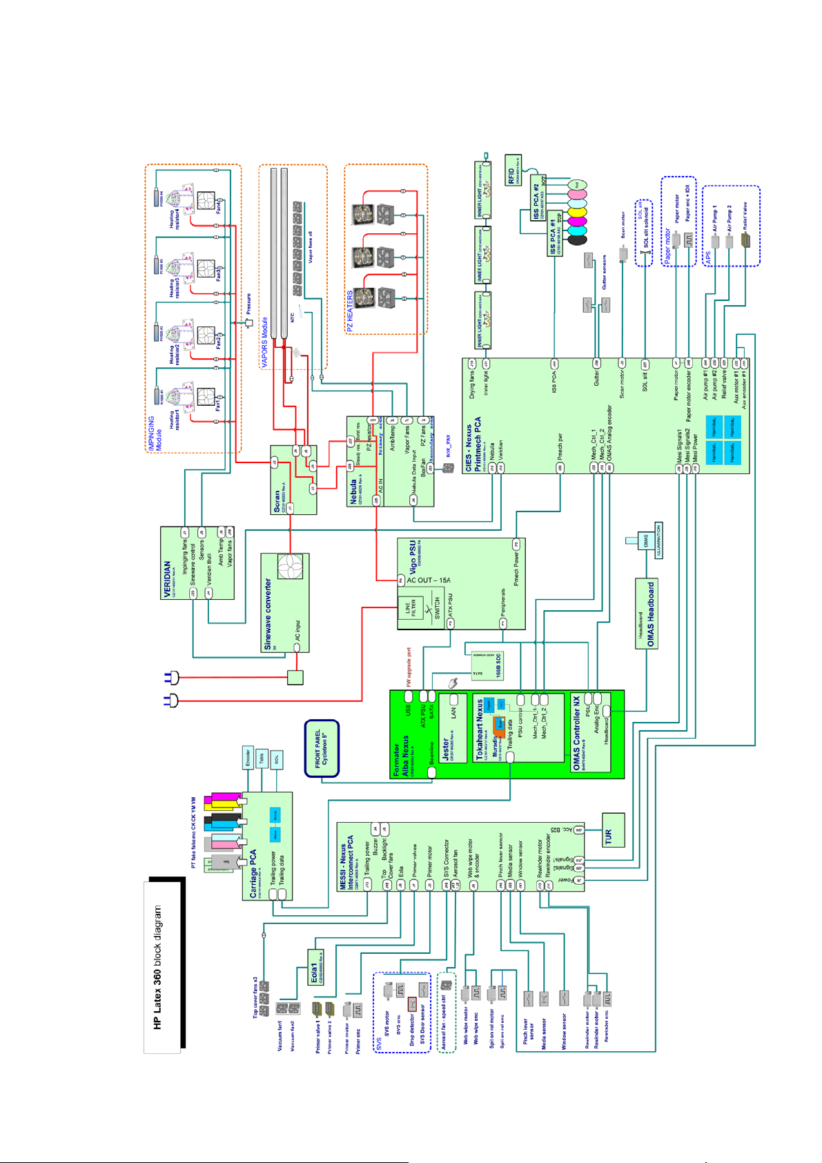
Block diagrams
HP Latex 360
ENWW Electrical system 3
Page 15
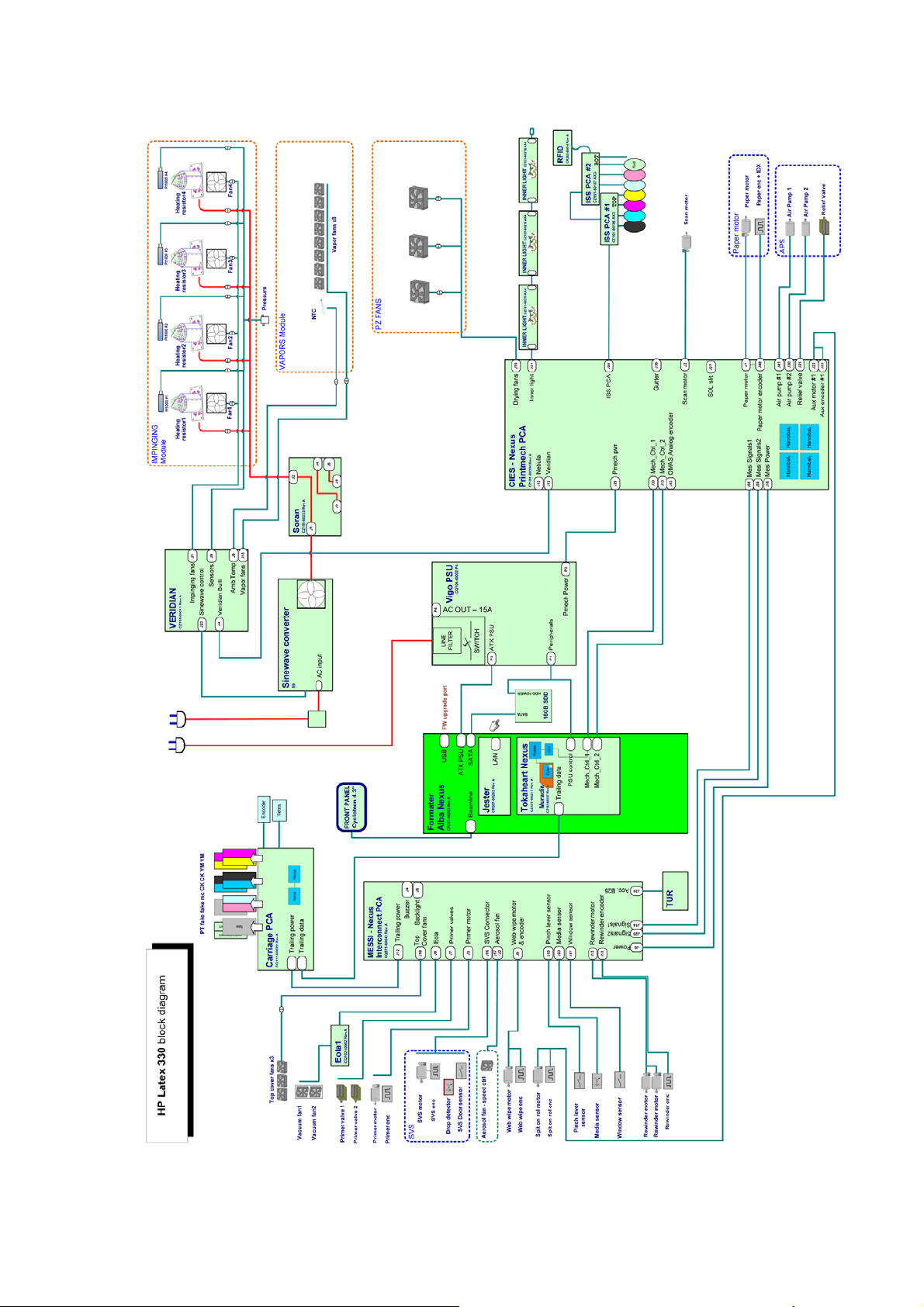
HP Latex 330
4 Chapter 1 Printer systems ENWW
Page 16
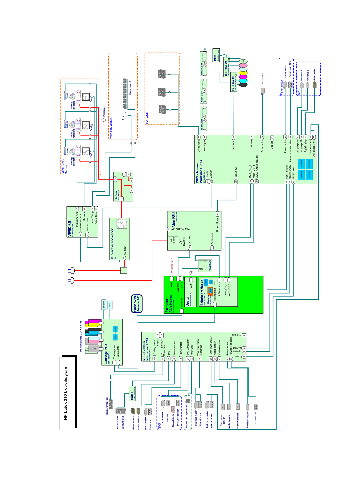
HP Latex 310
ENWW Electrical system 5
Page 17
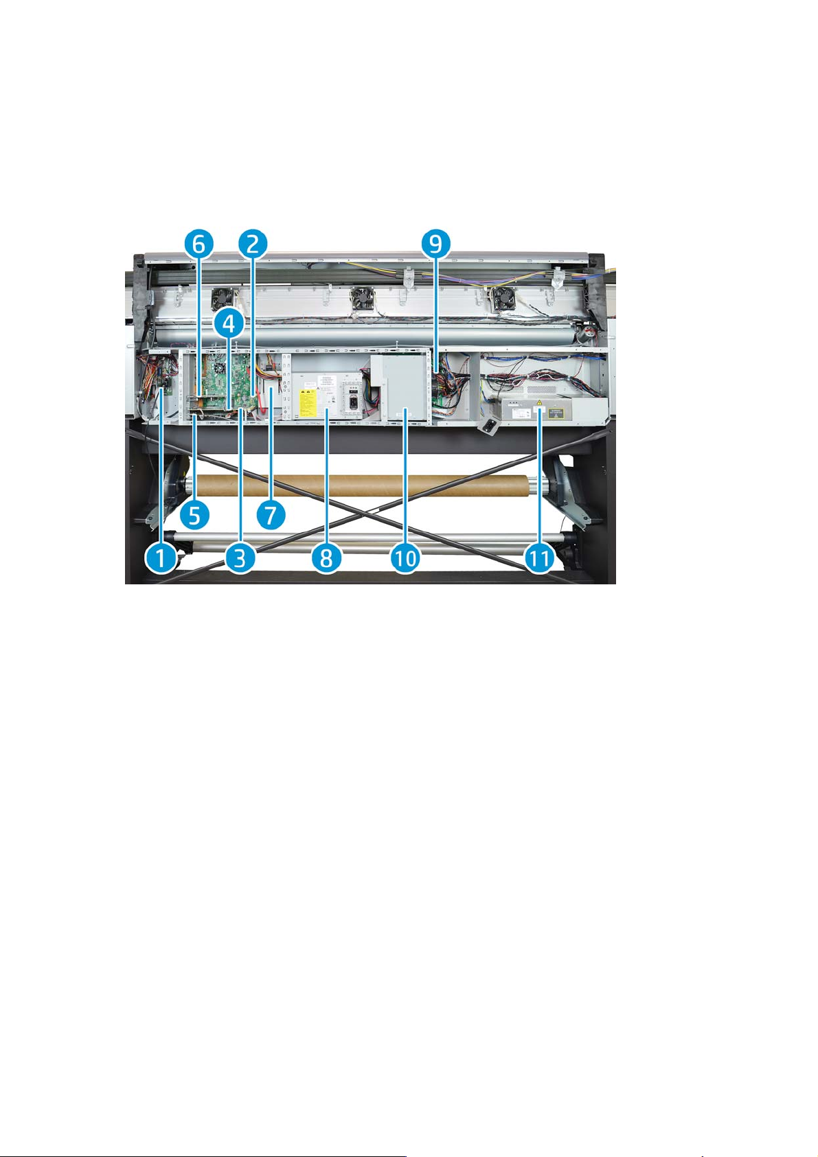
E-Box Components
Description
The E-box contains most of the electronics of the printer.
Components
1. Interconnect PCA
2. Formatter PCA
3. Engine PCA
4. Printer ID PCA
5. OMAS PCA
6. LAN PCA
7. Solid State Disk Drive (SSD)
8. Power Supply Unit (Main PSU)
9. Printmech PCA
10. Air Curtain and Printzone Heaters control PCA
11. Heater Control
Functionality
Interconnect PCA
The Interconnect PCA is an interconnect board with connectors that helps distribute power, and control
signals from the Printmech board, to all the elements connected to the right side of the machine, including
the following:
6 Chapter 1 Printer systems ENWW
Page 18

●
Take-Up Reel
●
Vacuum Fans (passes through; the actual control is inside Eola)
●
Valves and Motors for Primer, Rack Engage, SVS, and Aerosol Fan
●
Top Cover Fans
●
Rewinder Motor
●
Pinch Lever, Media and Window Sensors
Formatter PCA
The motherboard of the printer. It is the same type of board as found in a standard computer.
Engine PCA
The main controller of the printer. It is responsible for all the processes performed in real-time, and is the
ultimate controller of all electromechanical systems. The Engine PCA controls all substrate path components
(Drive Roller, Spindle Motors, OMAS, etc.), and all non-substrate path components (Carriage, Scan Axis Motor,
Print Head Cleaning Assembly, Service Station, etc). Attached to this board, is the Printer ID PCA.
Printer ID PCA
Contains printer identification. When replacing the Engine PCA, take care not to lose it.
OMAS PCA (360 only)
Controls the Optical Media Advance Sensor, used to measure substrate advance.
LAN Communication Card
Provides LAN communication.
Solid State Disk Drive (SSD)
Contains:
●
The printer firmware
●
The operating system
●
All calibration values, product number, serial number, and so on. In order to avoid loss in the case of
SSD failure, a backup is made in the ISS top board.
IMPORTANT: In order to prevent any loss of calibration values, do not replace the following at the same
time:
●
The Hard Disk Drive and the ISS Top Board.
Power Supply Unit (Main PSU)
This PSU delivers power to all the parts of the printer except heater elements. The internal rails are: 5V_sb;
3V3, 5V, 12V, 24V, and 42V.
PrintMech PCA
The PrintMech PCA is mainly used to control the mechatronics of the printer. For routing reasons, only the
parts connected to the left side of the printer are connected to this board:
●
Scan-Axis Motor
●
Substrate-Axis Motor
●
Ink Pressurizing Pumps and Valve
ENWW Electrical system 7
Page 19
●
Ink Collector Sensors
●
Ink Supply PCAs Connection
●
Inner Light PCAs Connection
●
Spit-on-Roll Motor (routed to the right side of the printer)
The remaining functionality implemented in the PrintMech PCA is sent to the right side of the printer through
the Mini Interconnect PCA and its three cables (power + data).
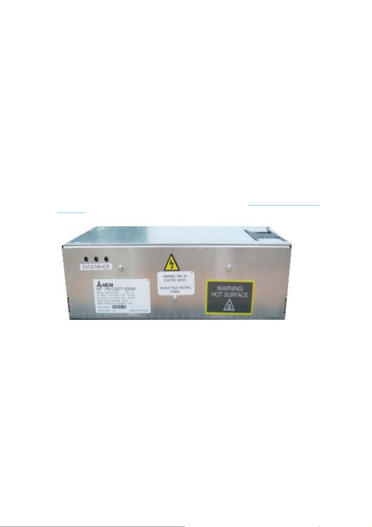
Heater Control
Converts the input voltage from the mains to a voltage in the output that is controlled by the Curing Control
PCA, and depends on the quantity of power required for impinging.
The converter has three cables: one power cable for the input, one for output, and finally the control cable.
The control part of the converter that interfaces with the Curing Control PCA is powered at 24 V.
There are three LEDs: Status (off or fault), PWM (if power is being delivered to the output), and ACOK (if Vin is
in range).
Air Curtain and Printzone Heaters control PCA
Controls the Air curtain and Printzone Heaters. For further details refer to:
on page 11.
Carriage Electronics
Description
The carriage contains electronics for controlling and firing printheads. It also contains electronics for
controlling the external sensors (SOL and Tetris) and the scan-axis encoder.
Heating-System Electronics
The electronics of the carriage receive power and data from the trailing cables, which include both power
(+42V) and data (LVDS) cables. The power cable connects the carriage with the Mini interconnect board, and
the data cable connects the carriage with the engine PCA.
Components
Carriage PCA
The carriage PCA contains electronics that control how and when the ink is dropped from each printhead. It
receives information from the sensors.
8 Chapter 1 Printer systems ENWW
Page 20
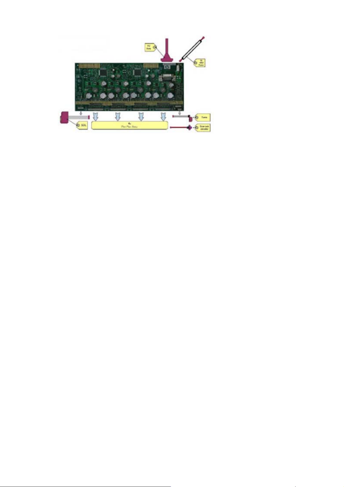
SOL Spectrophotometer (HP Latex 360)
The SOL is a color sensor located on the left side of the carriage. The main function of the SOL is to measure
color samples printed on the loaded substrate, and then placed in the print platen zone.
Before taking any color measurement, the SOL must be initialized. The SOL initialization process takes
approximately 7 minutes. This process consists of three steps:
●
Sensor switch on
●
Sensor warm up
●
Sensor calibration
When the initialization process has finished, the shutter opens automatically and the carriage is moved along
the scan axis to place the SOL on top of each sample and take a color measurement. After the
measurements, the shutter is closed, and the sensor is switched off.
Tetris
The Tetris is used to align the printheads, and to locate the edges of the substrate and measure its size. The
alignment procedure consists of a series of patterns first printed, then scanned using the Tetris, and finally
an internal process is used to correct the timing of when and where the nozzles of the printheads fire, and
detect any possible nozzle-out issues.
Scan-axis encoder
The line encoder is located on the carriage; it measures and counts the movements of the scan axis. An
optical, infrared wavelength encoder is used: the same type of encoder used in most of the HP large-format
printers. The encoder signal is converted to LVDS logic levels, and directly routed through the data TC.
Printhead flex
To connect the carriage to the printheads, a delicate flexible circuit with small golden dimples is used.
Printheads are inserted into unique slots and a spring-loaded mechanism pushes the electrical contacts of
the printheads into the printhead flex, which subsequently connects the printhead to the carriage electronics.
Printhead flexes are the most delicate and sensitive part of the carriage. If the printheads are inserted with
too much force, or they are misaligned, they can easily be damaged.
Ink Supply Station (ISS) Electronics
Description
There are two ISS PCAs (as in the DJ L25500/L26500 printers).
ENWW Electrical system 9
Page 21
Components
Top and bottom ISS PCAs
The ISS electronics are powered from a +12 V line coming from the PrintMech, and a linear regulator on the
ISS PCAs generates the +5 V used to power all the devices on the board.
The ISS PCAs are two electronic PCAs located at the rear of the Ink Supply Station. The ISS PCAs provide the
following:
●
●
●
●
●
●
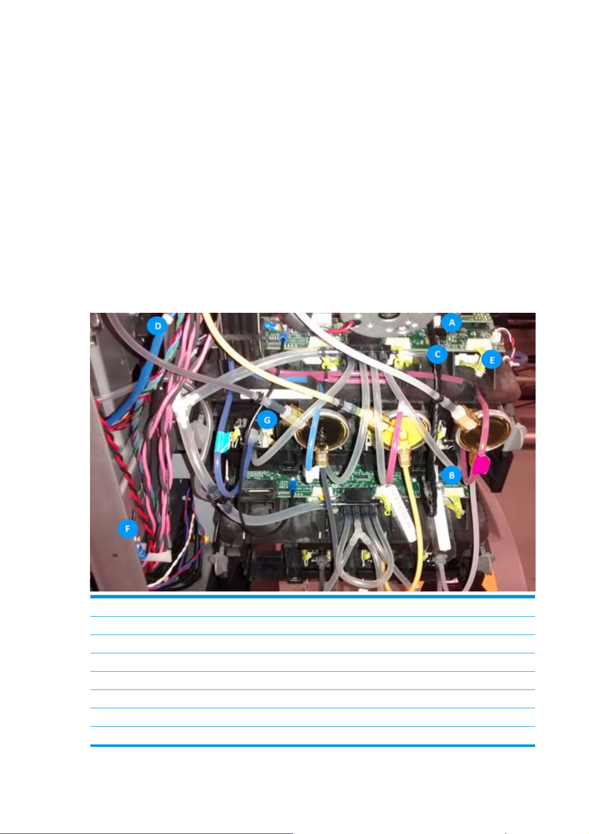
Below is a picture showing the connections and components located at the rear of the ISS.
Ink-Supply presence detection
Ink-Cartridge broken-bag detection
Ink-Supply smart-chip interface
Air-Pressure measurement and air-pump shutdown
Humidity and temperature measurements
System back-up EEPROM
Marking Description
AISS Top PCA
BISS Lower PCA
C Cable: ISS Top PCA to ISS Lower PCA
D Cable: ISS Top PCA to PrintMech PCA (blue)
E Cables (6): ISS PCAs (Top and Lower) to Ink Cartridge and PIP
F ISS grounding cable
GPIP sensor (6)
10 Chapter 1 Printer systems ENWW
Page 22
Both top and bottom ISS PCAs share the same PCB; the only difference between them is that the bottom PCA
is a simplification of the top PCA. The top PCA contains these additional parts:
●
EEPROM
●
Connection from the PrintMech PCA
●
Air pressure sensor
●
Temperature and humidity sensors
Both PCAs are connected through an 8-pin connector. The second ISS connector is connected to the
PrintMech PCA in a daisy-chained connection, the first ISS board by means of this 8-pin connector.
Vacuum-Fan Electronics
Description
There is one EOLA PCA to control two different brushless blowers generating the required vacuum to hold the
substrate. This PCA is connected to the Mini interconnect PCA (right side).
Heating-System Electronics
Description
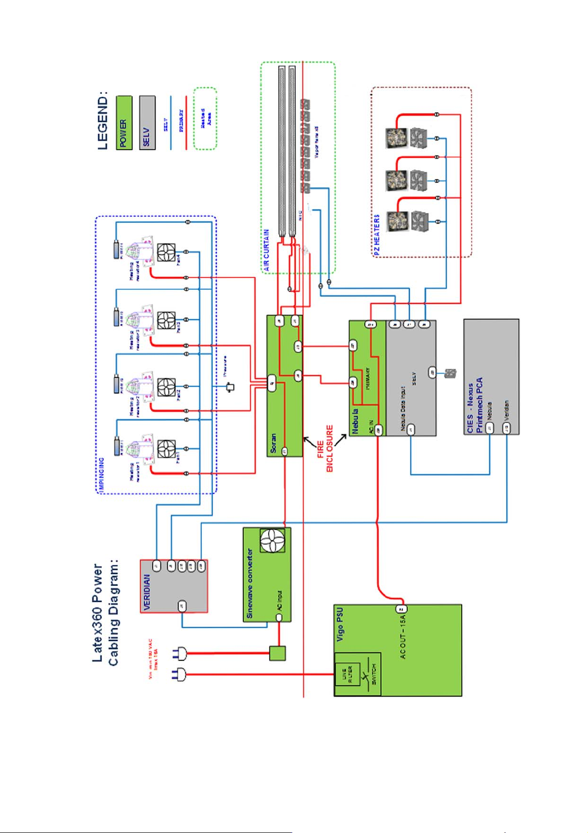
In the Latex 360 Power, power is delivered to 3 subsystems:
●
Impinging (Drying and curing): Controlled through Curing Control PCA
●
Air curtain: Controlled through Air Curtain and Printzone Heaters Control PCA
●
Print zone heating: Controlled through Air Curtain and Printzone Heaters Control PCA
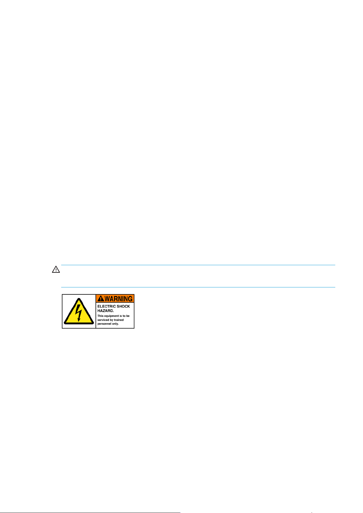
WARNING! The PRI (POWER) area is not isolated, and there is an electrical shock hazard. The PCA is
connected directly to the AC mains input. The power cords should be disconnected before manipulating the
power elements.
The following diagrams show configuration, the Primary area, and its connection:
ENWW Electrical system 11
Page 23
Components
Air Curtain and Printzone Heaters Control PCA:
12 Chapter 1 Printer systems ENWW
Page 24
The Air Curtain and Printzone Heaters Control PCA is only present in Latex 360 printers, and is placed inside
the EEbox. The Air Curtain and Printzone Heaters Control is the PCA that controls the power delivered to the
air curtain resistors and the printzone heaters. The AC power input comes from the Main PSU, but there is a
pass through from the input power plug to the PCA AC input. The PCA has a primary non-isolated area, and a
SELV isolated area. The power available is balanced between both subsystems based on burst control, the
control is provided from the same PCA. The Air Curtain and Printzone Heaters Control also controls both
subsystems' fans; the ambient temperature sensor, and the box fan installed for cooling the PCA.
Curing Control PCA:
The Curing Control PCA is placed at the impinging bracket on its left side and executes the servo that applies
the power to the impinging module. The Curing Control PCA is present in all three SKUs; In the Latex 360
printer it controls the impinging sensors (Temperature and pressure) and the Heater Control, and in the Latex
330 & Latex 310 printers, it controls the air curtain fans, and reads the ambient temperature sensor. The
Curing Control PCA has no power (PRI) lines.
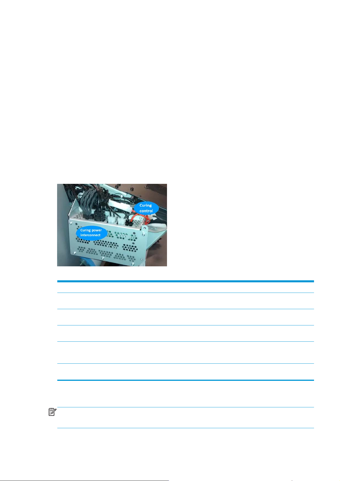
Curing Power Interconnect:
The Curing Power Interconnect PCA is placed just above the Curing Control PCA. Both PCAs are housed in the
same fire proof box. The Curing Power Interconnect PCA is connected to power lines and provides the
interconnection interface for the curing module, and for the air curtain resistors (Latex 360 only). The Curing
Power Interconnect PCA is present in all three SKUs.
Table 1-1 Connection differences between SKUs in the Heating System:
Ambient temp. sensor Air Curtain and Printzone
Printzone fans Air Curtain and Printzone
Air curtain fans Air Curtain and Printzone
Air curtain resistors Air Curtain and Printzone
Printzone resistors Air Curtain and Printzone
Electrical configuration
NOTE: An electrician is required for the setup and configuration of the electrical system used to power the
printer. Make sure that your electrician is appropriately certified according to local regulations, and supplied
with all the information regarding the electrical configuration.
HP Latex 360 HP Latex 330 HP Latex 310
Curing Control Curing Control
Heaters Control
Printmech Printmech
Heaters Control
Curing Control Curing Control
Heaters Control
xx
Heaters Control/Curing Power
Interconnect
xx
Heaters Control
ENWW Electrical system 13
Page 25

Your printer requires the following electrical components to be supplied and installed by the customer,
according to the Electrical Code requirements of the local jurisdiction of the country where the equipment is
installed.
Single-phase power
Table 1-2 Single-phase line specifications:
HP Latex 360 HP Latex 330 HP Latex 310
Printer Curing Printer Curing Printer Curing
Number of
power cords
Input voltage ~200-240 V +-10% (two wires and protective earth)
Input frequency 50 / 60 Hz
Maximum load
current (per
power cord)
Power
consumption per
power cord in
printing mode
Power
consumption in
ready mode
Circuit breakers
NOTE: The circuit breakers must meet the requirements of the printer and be in accordance with the
Electrical Code requirements of the local jurisdiction of the country where the equipment is installed.
The printer requires two power cords that meet the following requirements.
Table 1-3 Dedicated lines per SKU:
222
16 A 16 A 3 A 16 A 3 A 13 A
2.5 kW 2.1 kW 200 W 2.4 kW 200 W 2.0 kW
85 W 72 W 70 W
HP Latex 360 HP Latex 330 HP Latex 310
Printer Curing Printer Curing Printer Curing
Dedicated line Yes Yes Not required. Do
Branch circuit
breaker
Residual current
circuit breaker
(1)
2 poles, 16 A/20 A according to local laws and printer maximum load current
Required Recommended Recommended
not overload
lines. See Table
2-3
2 poles, 30 mA residual, at least 20 A capacity
Yes Not required. Do
not overload
lines. See Table
2-3
Not required. Do
not overload
lines. See Table
2-3
(1) Also known as Ground Fault Circuit Interrupter (GFCI)
14 Chapter 1 Printer systems ENWW
Page 26
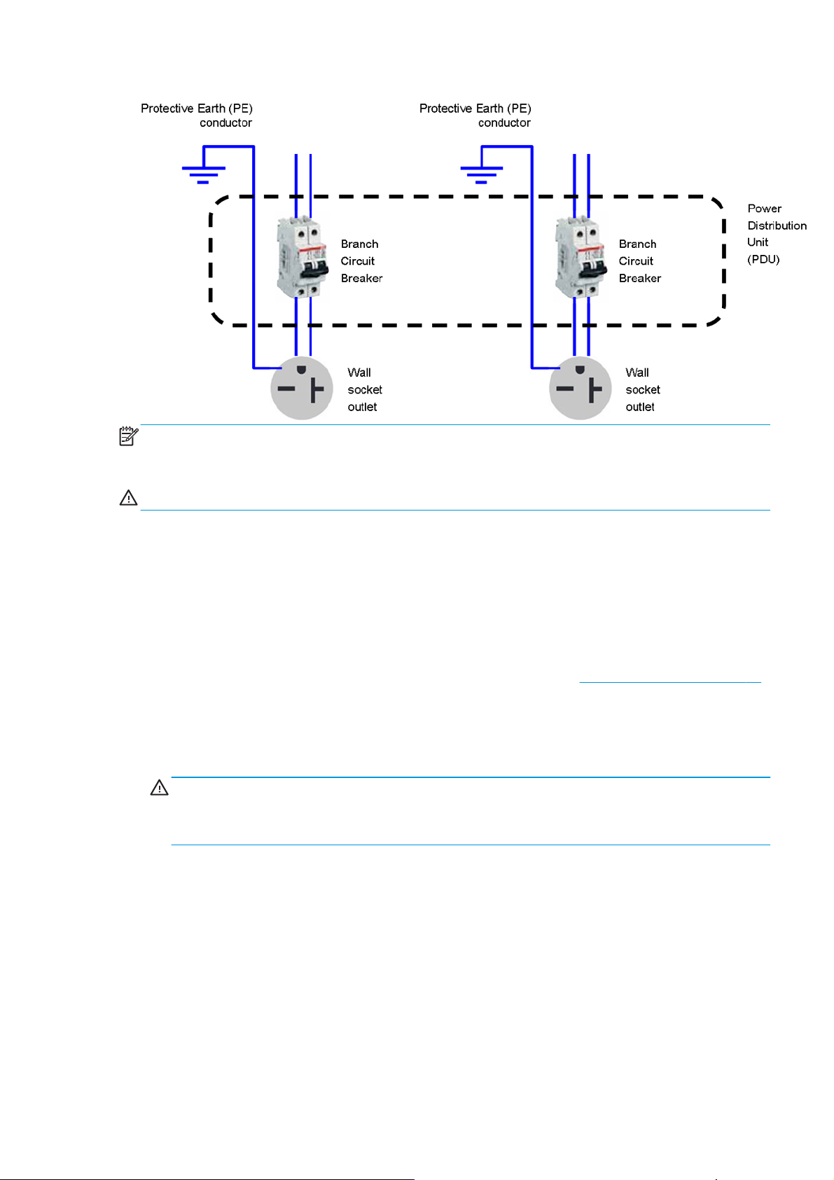
Figure 1-1 Electrical configuration diagram (for reference only)
NOTE: The Power Distribution Unit (PDU) must be rated to meet the power requirements of the printer, and
be in accordance with the Electrical Code requirements of the local jurisdiction of the country where the
equipment is installed.
WARNING! Do not use a power strip (relocatable power tap) to connect both power cords.
Wall receptacles and power cords
Two power cords are provided with your printer, according to the printer's electrical specifications. If those
cords do not reach your PDU and/or UPS, a certified electrician must install suitable extension cables on the
day of installation.
To make sure you have the right wall socket outlets (wall receptacles) ready for installation, check the
following:
1. The wall socket outlets must be suitable for printer input ratings. See
2. The wall socket outlets must be suitable for the power cord plug type used in the country of
installation. The list shows examples of the power cords and the plugs provided with the printer
according to the country. To make sure you have the right wall receptacle, find your country in the
appropriate table and check the plug type.
WARNING! Only use the power cord supplied by HP with the printer. Do not use a power strip
(relocatable power tap) to connect both power cords. Do not damage, cut, or repair the power cord. With
a damaged power cord, there is risk of fire and electric shock. Always replace a damaged power cord
with an HP-approved power cord.
Table 1-4 HP Latex 330/360 Printers— Printer power cord specifications:
Single-phase power on page 14.
ENWW Electrical system 15
Page 27
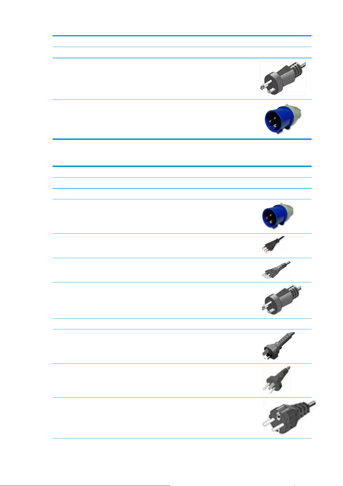
NOTE: For HP Latex 330/360 Printers— Use two power cords from below
Country HP Part Number * Length Plug type Plug
USA, Canada, Mexico,
Japan, Philippines, Thailand
International 8120-6897 4.5 m IEC 60309, 240 V, 16 A, 2L
8120-6893 4.5 m NEMA 6-20P, 240 V, 20 A,
non-locking
+PE
Table 1-5 HP Latex 310 Pinter — Power cord specifications per region:
NOTE: For HP Latex 310 Printers — Use two power cords from below
Country HP Part Number * Length Plug type Plug
America Region
Argentina 8120-6897 4.5 m IEC 60309, 240V, 16A,
2L+PE
Brazil 8121-110 2.5 m NBR 14136
Chile, Uruguay 8121-0923 2.5 m CEI 23-50
USA, Canada, Mexico 8120-6360 2.5 m NEMA 6-20P, 240 V, 20
A, non-locking
Asia Pacific and Japan Region
Australia/New Zealand 8120-6351 2.5 m AS/NZS 3112-3 (15A)
China 8121-0924 2.5 m GB 1002 (16A)
Korea, Indonesia 8120-6352 2.5 m CEE 7-VII
16 Chapter 1 Printer systems ENWW
Page 28
NOTE: For HP Latex 310 Printers — Use two power cords from below
Country HP Part Number * Length Plug type Plug
India 8121-1074 2.5 m IS 1293
Taiwan 8121-1033 4.5 m CNS 690
Hong Kong, Singapore 8120-6898 4.5 m BS 1363/A (13A fused)
Japan, Philippines,
Thailand
Europe, Middle East and Africa Region
Europe Russia 8120-6352 2.5 m CEE 7-VII
Denmark 8121-1077 2.5 m DK 2-5A
Israel 8121-1010 2.5 m SI 32
South Africa 8121-0915 2.5 m SABS 164
8120-6360 2.5 m NEMA 6-20P, 240 V, 20
A, non-locking
Switzerland,
Liechtenstein
8120-6897 4.5 m IEC 60309, 240 V, 16 A,
2L+PE
ENWW Electrical system 17
Page 29
NOTE: For HP Latex 310 Printers — Use two power cords from below
Country HP Part Number * Length Plug type Plug
U.K. 8120-6898 4.5 m BS 1363/A (13A fused)
Middle East 8120-6360 2.5 m NEMA 6-20P, 240 V, 20
A, non-locking
Table 1-6 Appliance coupler (printer connection):
Country Appliance coupler (power cable) Appliance coupler inlet (printer)
All Detachable terminal as per IEC60320-1 C19
(squared type)
NOTE: Place the wall receptacle close enough to the printer so the plug can be plugged and unplugged
easily.
Electronic Cables Routing
This section can be used as a reference section, to check the original routing of the cables
Detachable inlet as per IEC60320-1 C20 (squared
type)
18 Chapter 1 Printer systems ENWW
Page 30
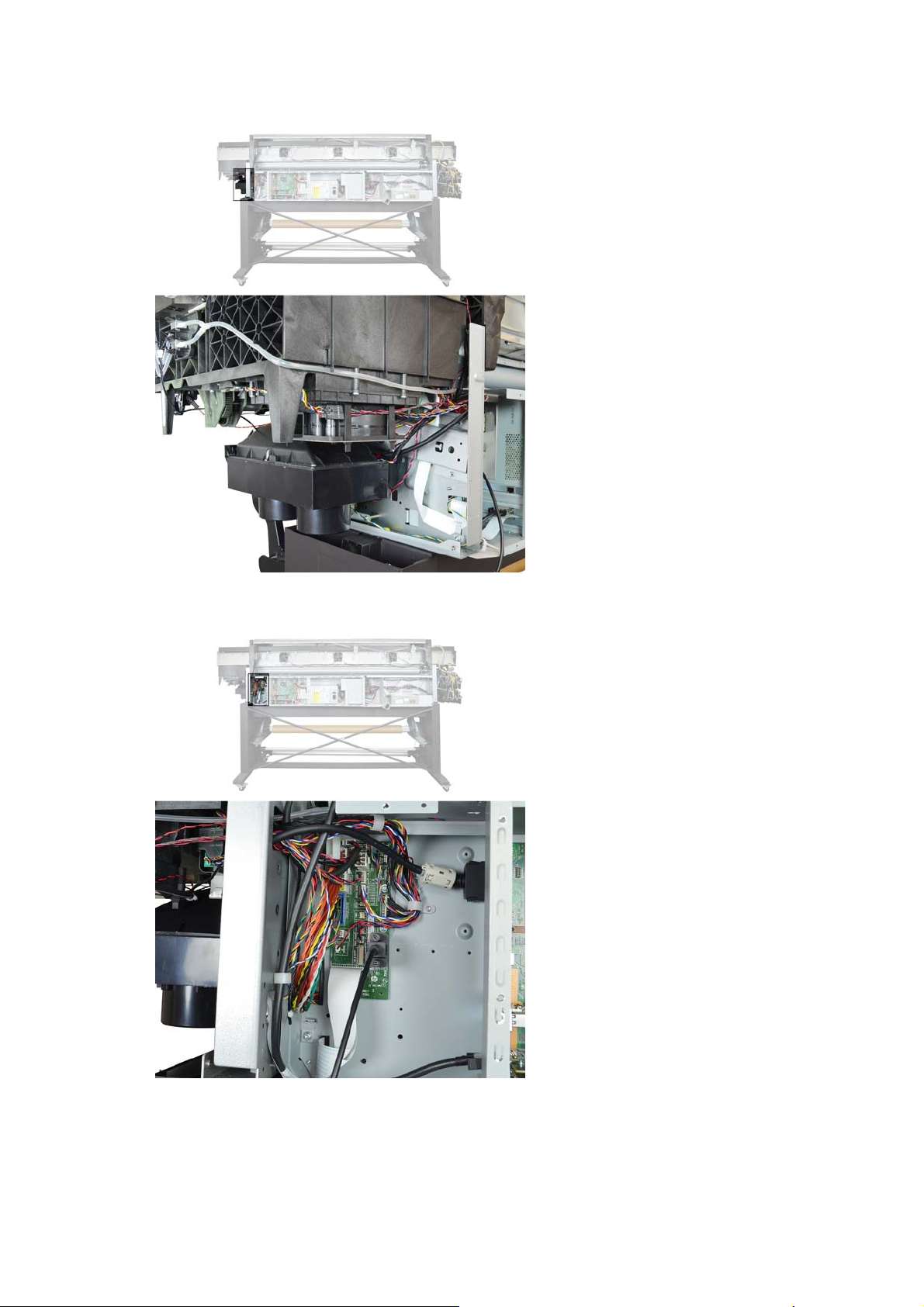
Rear Service Station Cables Routing
Interconnect PCA Cables Routing
ENWW Electrical system 19
Page 31

Electronics Main PCA Cavity Cables Routing
Printmech PCA Cables Routing (behind Heaters Control Assembly)
20 Chapter 1 Printer systems ENWW
Page 32

Left Interconnect Cables Routing
Left End Rear Chassis Cables Routing
ENWW Electrical system 21
Page 33

Rear ISS Cables Routing
Substrate path
Description
The substrate path moves the substrate from the input spindle to the take-up reel, through the print path,
while the carriage prints on the substrate. The objectives of the substrate path while advancing the substrate
are:
●
Maintain an accurate advance
●
Maintain a constant advance
●
Keep the substrate flat
●
Advance the substrate straight along the substrate axis
Substrate path workflow overview
The following steps describe the substrate path workflow.
22 Chapter 1 Printer systems ENWW
Page 34

1. The substrate is loaded onto the input spindle (1), which is driven by the rewinder mechanism to
provide back tension to the substrate. The substrate is fed through the input platen where an optical
sensor detects substrate presence, around the drive roller (2), under the pinchwheels (3), over the
print zone (4) and the overdrive platen (5), and finally it is either left free or looped through the
diverter (6) through the tension bar (7) to be collected on the take-up reel (8).
2. The rewinder has a motor that primarily acts as a brake to maintain tension on the substrate. The
rewinder may turn in either direction, depending on which is the printable side of the input substrate roll
and its winding direction.
3. The drive roller also has a motor, and is the primary component that advances the substrate. The
substrate is pressed to the drive roller by the pinchwheels, ensuring a smooth substrate advance. The
motor receives feedback from an encoder located at the left side of the roller, inside a protected
enclosure on the left of the left sideplate.
4. The surface of the substrate path where the substrate is printed is called the print platen. The print
platen is designed to give minimal resistance to the substrate advance, and includes suction holes that
apply vacuum to the substrate.
5. The printer detects and controls the substrate advance. The OMAS sensor, located on a special cut-out
section of the print platen, is a sensor that is able to detect very small errors in the advance of the
substrate. These errors are communicated to the motors on the drive roller, and small correctional
adjustments are applied to the movement of the substrate.
NOTE: The OMAS sensor cannot see the fibers on some substrates, such as transparent substrate or
very dark or very reflective substrates. In these cases, the OMAS sensor can be disabled. To disable the
OMAS sensor, see
1.3.3 Enable/Disable OMAS on page 167.
6. The vacuum pressure is adjusted depending on the substrate type and print options used. It draws the
substrate to the print platen, making sure that the substrate is flat.
7. After the platen, the substrate goes through the curing zone and finally leaves the printer, either to be
collected on the take-up reel or to be cut.
8. When the take-up reel is in use, the substrate must be threaded, first passing in front of the loading
table used as a diverter, then under the tension bar and rerouted to the output roll loaded in the takeup reel. This system creates tension on the outgoing substrate for proper winding. The take-up reel can
operate in both directions with the rewinder, winding with the printed face outside or inside.
Startup, substrate load, substrate selection
During startup, the printer checks that the substrate path components are functioning correctly. When
shutting down, if a substrate is loaded, the printer remembers the substrate definition. This may be modified
through the front panel with the option ’Change loaded substrate’ from the substrate menu list.
ENWW Substrate path 23
Page 35

During substrate loading the printer may ask the user two interactions:
1. To rewind manually the substrate: The printer automatically checks the direction of the loaded
2. To align the substrate in order to avoid skew: the printer measures skew. If the skew is too large the
Components
Spindle
substrate (printed face outwards or printed face inwards). If the ’curve’ of substrate is too large the
printer cannot detect it and the printer asks the user to rewind manually. Once the substrate is rewound
the printer can detect automatically
printer will ask the user to lift the pinchwheels (big blue lever on right hand side), and align the
substrate. The substrate must be aligned against itself (substrate edge must be aligned with input roll
edge).
The aluminum spindle of the 360 printer can load 3-inch core rolls. The 2-inch spindle of the 310 and 330
printers has an adaptor for 3-inch cores.
The spindle holds the core of the roll when its rubber bands are nipped between the core of the roll and the
aluminum extrusion.
On the 3-inch spindle, the hub on the left side has two possible fixed positions: the end position allows
loading maximum width rolls, but there is a second position at 2.6 inches (65 mm) from the end that can be
selected.
The right hub can be set along any length of the spindle so any length of roll can be loaded.
The right end of the spindle contains a gear which is used to transmit the movement from the rewinder to the
roll.
24 Chapter 1 Printer systems ENWW
Page 36

Spindle latch
The spindle latch prevents the substrate roll from slipping from its position when printing. It is not necessary
to close it when inserting the spindle, it closes automatically. But the user must lift the small blue lever in
order to release the spindle and extract the roll of substrate.
Rewinder
The rewinder motor keeps constant tension on the input substrate to prevent skew problems. There is a
motor and a transmission that gives torque to the spindle in order to provide the necessary back tension.
Substrate sensor
The Input Platen has an optical sensor that detects substrate presence. When the substrate is inserted into
the entry area, the sensor is activated and the drive roller starts turning to help the loading process. The
substrate load process has been triggered and the printer will provide instructions through the front panel.
When the substrate roll is exhausted and the bottom edge clears the substrate sensor, printing is
interrupted.
ENWW Substrate path 25
Page 37

OMAS sensor (substrate advance sensor)
OMAS is located under the third front platen slab from the right only the top window can be seen:
OMAS is composed of two parts: the sensor and its optics located under the platen and a PCI control board on
the main electronics box. Both are connected through a ribbon cable that runs through the vacuum beam, by
the right sideplate, and into the electronics box.
The optical sensor detects the surface of the back of the substrate as it moves across the platen. The sensor
is able to evaluate the exact movement of the substrate, and communicate any small adjustments required
by the system to move the substrate accurately.
The window of the OMAS sensor must be cleaned of dust and ink to work correctly. The cleaning procedure is
described in the user’s guide, in the section ‘Clean the substrate-advance sensor window’.
During the substrate load, the printer detects that the substrate has reached the print platen when the OMAS
captures its image.
NOTE: The OMAS sensor cannot detect the surface of some substrates, such as plastic or very dark ones. In
these cases, the OMAS sensor must be disabled, and instead the printer uses feedback from the Driver Roller
encoder to calculate the substrate advance. To disable the OMAS sensor, locate the OMAS Sensor selector
from the print options menu of the RIP and set it to OFF. This can also be done from the Service menu
Enable/Disable OMAS on page 167.
Drive roller and motor
1.3.3
The drive roller and motor advance the substrate through the substrate path. The motor requires 42 V, and is
controlled by the Printmech PCA.
The drive roller receives the torque from the motor through a worm as in the Z6100 and other Designjets.
Drive roller encoder disc and encoder PCA
The Drive Roller Encoder Disc and Encoder PCA provide the feedback system for the Drive Roller.
26 Chapter 1 Printer systems ENWW
Page 38

●
The Encoder disc is a round disc mounted to the left end of the Drive Roller.
●
The Encoder PCA is mounted with a sensor that reads the encoder movements of the disc (the disc turns
with the drive roller).
Pinchwheels
The pinchwheels press the substrate against the Drive Roller to make sure that the Drive Roller can advance
the substrate correctly.
●
The pinchwheels are activated with the blue lever at the right side of the substrate roll and usually do
not have to be lifted unless to correct skew during substrate load or to clear jams.
●
The pinchwheel system has a sensor that detects if the system is up or down.
Vacuum pump, vacuum tube assembly, vacuum beam
The print zone is the area of the substrate path where the transmission of ink to the substrate occurs. The
main function of the system can be defined as providing the surface where the substrate is printed, keeping it
controlled during the process, playing a main roll on the final IQ of the plots and on the operational reliability
of the printer. The subsystem is composed of the print platen assembly, which is the physical interface with
the substrate, and the vacuum system which is the mechanical system where the vacuum pressure used to
control the substrate is generated and conduced.
The platen gives a convenient shape to the wet substrate, avoiding uncontrolled expansion of the substrate.
The main components are:
●
Platen assembly
◦
Front platens, rear platens, OMAS platen
◦
Linear blade 64-inch + springs (same as DJ Z6100 or L26500)
◦
Foams, foam fillings, and foam wall
●
Right vacuum fan assembly with EOLA control board (as with the HP Designjet Z6200 or T7100)
Related tests, utilities, and calibrations
●
Rewinder test
●
Drive Roller test
●
Substrate Path sensor test
●
Vacuum Test
●
OMAS Test
●
Rewinder Motor polarity test
●
Substrate path menu
2.1 Rewinder System on page 147
2.2 Drive Roller on page 147
2.3 Substrate Path Sensors on page 148
2.4 OMAS Module on page 148
1.3 Substrate Path Menu on page 166
●
Substrate advance adjustment
2.3 Substrate Advance Menu on page 175
Service parts
●
Drive Roller
●
Substrate Path Assemblies
●
Center guide Pinchwheels Assemblies
ENWW Substrate path 27
Page 39

●
Substrate Entry Assemblies
●
Take-up reel Assemblies
Removal and installation
●
Rewinder
●
Vacuum Fan
●
OMAS
●
Output Platen
●
Print Platen
●
Input Roller
●
Output Roller
●
Substrate Sensor
●
Pinchwheel Assembly
●
Center Guide
●
Driver Roller
●
Rollfeed Modules
●
Take-up reel
28 Chapter 1 Printer systems ENWW
Page 40

Ink Delivery System (IDS)
Ink Delivery System
The ink deliver system (IDS) is located in the left enclosure of the printer (inside the left covers) and delivers a
continuous supply of ink to the printheads. It can detect an ink leakage anywhere in the system, including
inside an Ink Cartridge. It also tracks and determines when an Ink cartridge needs replacing.
Rear of the Ink Supply Station
ENWW Ink Delivery System (IDS) 29
Page 41

Ink tubes
There are 6 ink tubes that deliver the inks to the printheads in the carriage and two additional tubes which
are used as a support structure. They are bundled together in a carrier and held on a shelf on the inside of the
top cover with clips.
Insulation sleeve
The ink tubes are protected from the high temperatures of the Dryer Assembly by a heat resistant insulation
sleeve, which protects the main body of the tubes that are static.
Upper and lower Ink Supply Station (ISS)
The Ink Supply Station (ISS) is divided into the upper and lower sections. They have six slots for holding the
ink cartridges. Each slot has a unique shape (or lock out) which matches with an equal shape at the end of the
applicable ink cartridge. this arrangement avoids the incorrect insertion of an ink cartridge, which would
cause major damage to the ink system.
There are two places for additional slots but these are covered over.
The upper and lower ISS both contain PCAs, although the top PCA contains more functionality, such as the
pressure sensor, see
Ink Supply Station (ISS) Electronics on page 9.
Non-return valves
The two non-return valves are only for the inks on the lower IDS. This is to ensure that when the pump stops
and the cartridges are nearly empty, that the ink does not flow back to the cartridge.
Ink seals
If a cartridge is nearly empty, with no pressure from the pump, the cartridge bag might increase, and air
might enter the printhead.
With a valve, the ink can go only from the cartridge to the printhead, and not the reverse.
Ink seals interface each ink cartridge with the air and ink tubes. They also contain leakage and end-of-ink
sensors.
30 Chapter 1 Printer systems ENWW
Page 42

Air Pressure System (APS)
The APS contains two air pumps which are used to force the ink through the tubes to the carriage assembly.
In the event of a broken bag in one of the Ink Cartridges, these tubes must be checked in case any of the
leaked ink has been forced into the air tubes.
Related tests, utilities, and calibrations
●
Ink delivery system tests:
Service parts
●
Left-hand assembly
Removal and installation
●
Ink supply tubes and trailing cable
●
ISS to cartridge cables
●
Ink supply station
●
Ink supply station PCAs
●
APS assembly
3. Ink System Menu on page 149s
ENWW Ink Delivery System (IDS) 31
Page 43

Scan axis and carriage
Scan axis
The scan-axis system is the part of the scan-axis subsystem designed to move the carriage backwards and
forwards for printing and servicing. This subsystem moves the carriage with a motor, belt, and pulley system.
Furthermore, the scan axis has features to open and close the spectrophotometer shutter (SOL) and to
enable/disable the cutter.
Scan-axis components
Scan beam:
It is an extruded aluminum part. Its main function is to guide the carriage along the scan axis via two rods,
and it sets its limits of movement. Apart from this it positions and holds the service station, the scan-axis
motor, the two brackets, and the pinchwheels assembly. It also works as an air container to be blown to the
print zone coming from the rear and leaving through several pipes located over the substrate and holds the
rear fans.
PPS system
The PPS consists of some screws and pockets, it locates the scan beam in reference to the side plates in
order to have a correct distance between the printheads and the substrate. This distance is supposed to be
constant during the life of the machine and it is set to be as small as possible without taking the risk of
having the printheads touching the substrate.
Left bracket
The left bracket is an injected plastic part, and its main function is to set an end for the carriage movement. It
also closes the scan beam to avoid the air blown to the print zone leaking. It has several features to enable/
disable the cutter and the SOL shutter. The left bracket also houses the substrate jam sensor, which works
with the reflector panel on the carriage assembly to detect substrate crashes. It also has some parts to
ensure that the encoder strip is held with tension.
Encoder strip
The encoder strip contains positional data that the encoder sensor (located in the carriage) can read and
detect the position of the carriage. Since it is made of thin metal it is sharp and extreme caution is needed
when handling it.
Right bracket
This part is the same in the left bracket, this metallic part closes the right hole of the scan beam extrusion. It
also holds the pulley assembly and the encoder strip.
Motor, pulley assembly, and belt
Their function is to transmit the position/speed to the carriage assembly.
Flat right bump
This plastic part defines the right end of the carriage movement. It is positioned and held by the scan beam.
Carriage
The carriage is the subsystem of the printer that performs the printing on the substrate. It is moved across
the print path by the scan axis impelling system and with it the 6 printheads and several sensors, the
Spectrophotometer (SOL), the line sensor (Tetris), the scan axis sensor. The carriage houses an on-board
32 Chapter 1 Printer systems ENWW
Page 44

electronics system to send information to the 6 printheads though each of the interconnects, and it receives
information from the sensors. Some parts aid the ink to arrive at the printheads. It also holds in position the
cutter, used to cut some types of substrate.
Carriage components
SOL Spectrophotometer (360 only)
SOL is a color sensor and it is placed in the left side of the carriage, covered by a metal sheet that protects it
from the heater’s high temperatures. The main function of SOL is to measure color samples that have been
printed on the loaded substrate and are placed on the print platen zone.
Before taking any color measurement, SOL must be initialized. The SOL initialization process lasts for about
7min. This process consists on 3 steps: sensor switch on, sensor warm up, and sensor calibration. When the
initialization has been completed, the shutter is opened automatically and the carriage is moved along the
scan axis to place SOL on top of each sample to take a color measurement. After the measurements, the
shutter is closed again and the sensor is switched off.
SOL is used to make the linearization from the RIP.
Carriage base
The main function of this plastic part is to located the printheads. Its position is enforced by the two rods and
the belt. It serves as a base where other parts are attached and it has some features to located other
components (capping station and all the next parts).
Oiler
The Oiler is a small system at the right-hand side of the carriage base that provides continuous lubrication to
the Slider Rod.
Latch assembly
This assembly holds down the printheads and helps to ensure that they do not move during operation. Once
the handle is opened it can rotate to allow the user to remove the printheads. It has some features (holes) to
ENWW Scan axis and carriage 33
Page 45

allow the primer to pass through it and make contact with the printheads. Some parts help to transmit force
to the printheads holding them in position and transmitting information of when the ink should be dropped.
Under-carriage protector
This part covers the bottom area of the carriage in order to keep it clean. It also protects the printheads from
encounters with the substrate.
Sensors
The SOL, the Tetris, and the encoder sensor send information to the PCA board and is passed to the
printmech though the trailing cable. The SOL performs a color calibration, the line sensor calibrates the
printhead alignment and detects other features (e.g. the substrate), and the encoder sensor detects the
movement of the carriage in relation to the Encoder strip.
Carriage PCA
This part contains the electronics to control how and when ink is dropped into each printhead, and receives
information from the sensors.
PCA Cover
This part covers the PCA to avoid aerosol contamination and acts as an electronic enclosure.
X-bias springs
The X-bias springs are sheet metal parts that hold the printhead in position in the X axis.
Covering sheet and metal parts
Bushings are bronze parts that are attached to the carriage base and slide over the rod.
Felts help to lubricate the rod and they also stop dirt going in between the carriage. They block four degrees
of freedom (Z and Y translation and rotation over the primary rod)
SOL protectors help to avoid the SOL shutter breaking after a substrate jam.
Plastic rear bushing blocks one degree of freedom (the X rotation over the primary rod). The dam protector,
are Mylar and stainless steel, and they stop the aerosol.
The plastic non-functioning printhead, is a plastic part which helps keep the carriage’s integrity when the
latch is applied over them. Also from a usability point of view, they avoid possible mistakes when inserting
the printheads, and have a cosmetic function too.
The airflow deflector partially stops the air entering into the print zone, it is used to avoid vapor
concentration over the substrate that also causes “dpe” (drop placement error).
Related tests, utilities, and calibrations
●
Scan Axis Menu service tests:
●
Carriage service tests
5. Carriage Menu on page 157
4. Scan Axis Menu on page 156
●
Open/close SOL
●
Carriage Calibrations
4.3.3 Color-Sensor Shutter Calibration on page 186
4.3 Carriage Menu on page 182
Service parts
●
Right hand Assemblies
●
Left hand Assemblies
34 Chapter 1 Printer systems ENWW
Page 46

●
Carriage Assembly
●
Scan Axis Assemblies
Removal and installation
●
Cutter Assembly
●
Encoder Strip and Encoder sensor
●
Carriage Assembly.
●
Belt Assembly
●
Scan Axis Motor
●
Line Sensor
●
Color Sensor Assembly (SOL)
●
Color Sensor Actuator
ENWW Scan axis and carriage 35
Page 47

Service station and waste management
The main function of the service station is to maintain the printheads in the carriage assembly and to manage
the waste ink. The service station and waste management can be split into two subsystems:
●
PHC servicing, comprising cap, wiping, spitting, and priming functions
●
Waste management, which contains ink spit/aerosol ink collection and the aerosol filter
Components
SVS mechanics
The SVS mechanics provide the movement for the maintenance cartridge, which integrates the capping,
spitting, and wiping functions, and the cleaning roll assembly, which provides the means with which to
advance the cleaning roll accurately.
36 Chapter 1 Printer systems ENWW
Page 48

Primer
The primer executes the blow-primer functionality for the printheads. Air pressure to perform the prime
operation is drawn from the ink supplies, and the prime pulse is controlled by solenoid valves.
Maintenance cartridge
The maintenance cartridge is a customer consumable that holds the main components for wiping and
capping, and collecting ink from servicing operations.
Drop detector
The drop detector is a sensor that analyzes the nozzle health of all the printheads. The drop detector has a
window where it is placed; there, nozzles are fired to check their status. Nozzles that are out are detected
and compensated for by using other nozzles in order to maintain high print quality.
The drop detector has an infrared LED and a photodiode aligned in a beam light. This beam light can be
blocked if it is not placed correctly.
ENWW Service station and waste management 37
Page 49

Cleaning roll advance
The cleaning roll advance mechanism engages/disengages the advance gear of the maintenance cartridge.
The actual advance is achieved by moving the maintenance cartridge once the gear has been engaged by this
mechanism.
Spit roller turn
The spit roller turn mechanism engages, disengages, and turns the spit roller gear of the maintenance
cartridge.
Related tests, utilities, and calibrations
●
Service station service tests: see
●
Force drop detector: see
●
Drop detection calibration: see
●
Service station calibration: see
Service parts
●
Right-hand assemblies
Removal and installation
●
Primer assembly
●
Primer valves
●
Service station
●
Spit roller motor assembly
●
Cleaning roll motor assembly
●
Drop detector
●
Primer assembly
6. Service Station on page 158.
1.5.1 Force drop detection on page 168
4.2 Scan Axis on page 182
1.7 Service Station Menu on page 171
38 Chapter 1 Printer systems ENWW
Page 50

Heating system
The type of ink used in this printer (latex) requires heating for the ink to be cured. The heating system applies
heat through the Curing Assembly. The full SKU has additional heaters in the print zone and outlet.
Temperatures are kept at a target level depending on the type of substrate and amount of ink fired via
temperature sensors, which feed back information to the Heater Control assembly located at the rear of the
printer, and to the left of Curing Assembly.
Components
Heater control
For details, see
The following cross section shows the heating subsystems:
Heating-System Electronics on page 11.
Print Zone heating
The Print Zone heaters are installed in the scan beam in the full SKU only. They heat up the print zone to
25-35°C while printing. The main objective is to evaporate some of the ink, and raise the temperature for
satisfactory print quality.
The three resistors in the scan beam provide up to 1050W during warm-up.
Print Zone Fans
The Print Zone fans provide an airflow parallel to the substrate to reach a higher evaporation rate and push
the vapor out under the Curing Module to prevent condensation forming inside the printer.
ENWW Heating system 39
Page 51

Top Cover Fans
The Top Cover fans blow air from outside the printer along the inside of the window to avoid condensation
forming.
Curing Module
The Curing Module fixes the latex ink (cures) at around 80–116°C for satisfactory durability depending on the
substrate.
The four heaters (three in the 54” model) provide a total of 3090 W (2540 W). Each heater has a fan to build
up a chamber of hot air inside the Curing Module. This hot air, quite homogenous, is expelled onto the media
through an array of small holes.
For thermal efficiency, some air is redirected to the inlet of the heaters and passed through the pressure
chamber, before being expelled below the Air-curtain.
Air-Curtain
At the front of the Curing module is a row of fans that mixes the used air, full of vapor, with fresh ambient air.
This prevents the moisture in the air from forming droplets, which can cause condensation under certain
circumstances. It also lowers the air temperature that the operator is exposed to when standing in front of
the printer.
In the full SKU, with the higher throughput, heaters are included to heat up the ambient air before mixing it
with the air from the printer. These two resistors provide up to 2480 W during warm-up, reaching a working
temperature of 60°C while printing.
Pressure and thermal sensors
Each curing heater and fan has a thermal sensor. A pressure sensor, common for the entire curing module
and placed in a dedicated housing to assure adequate working temperature, is used to measure the pressure
inside the Curing Module. The sensor sends feedback to a servo in the Heater Control Assembly, and the
heater power and fan speed supplied to each module is adjusted according to target levels.
Thermal Switches
Each heater has a thermal switch. In the event of too high temperature, these will physically disconnect the
current from the heaters. These switches are integral parts of Print Zone and Curing heaters, while separate
in the air-curtain.
Impinging Deflector
At the inlet of each Curing Module heater, is a metal deflector. It prevents media jams, and also controls how
air is drawn in to assure media is exposed to uniform temperature.
Media Output Platen
The Media Output Platen is the part of the substrate path that is directly underneath the Curing Module. This
is a large sheet metal assembly that guides the media at optimal distance to assure complete curing. The
angle of the platen relative the Curing Module is important, as it affects how much air is leaving the printer,
and how much is being recirculated.
40 Chapter 1 Printer systems ENWW
Page 52

Related tests, utilities, and calibrations
●
Heating and Curing service tests:
●
Heating and Curing Temperature:
Service parts
●
Front Covers
●
Dyer and Curing Modules
Removal and installation
●
Heating Control Assembly
●
Dryer (IR) Heater Sensor
●
Dryer Heater Assembly
●
Curing Temperature Sensor
●
Curing Fans
●
Curing Heaters
●
Curing Module
Troubleshooting the printer heaters on page 52
Troubleshooting the printer heaters on page 52
ENWW Heating system 41
Page 53

Front panel
See the user’s guide for a description of the front panel and how to use it.
42 Chapter 1 Printer systems ENWW
Page 54

2 Troubleshooting
●
Troubleshooting the printer
●
Troubleshooting system error codes
●
Performing a service test on a failed assembly
●
Performing the necessary service calibrations
●
The printer does not power on
●
How to read the power switch LEDs
●
How to read the Formatter LEDs
●
How to read other LEDs
●
Voltage check at installation
●
Troubleshooting substrate jams or printhead crashes
●
The printer continuously rejects printheads
●
The cutter does not function (Latex 360 only)
●
Troubleshooting the printer heaters
●
How to interpret the service information pages
●
How to obtain the printer log and the diagnostics package
ENWW 43
Page 55

Troubleshooting the printer
Printer education and training
Before any attempt is made to troubleshoot the printer, it is critical that you have the relevant training on the
HP Latex 300 Printer series. If you are not trained on this printer, contact HP Education or HP Training to
enquire about becoming ‘HP Service Qualified’ for this printer.
Firmware update
The first step to take when trying to clear an error with the printer is to check that the firmware installed in
the printer is the latest available. Firmware updates often include fixes for common problems, and simply
updating the firmware can often resolve the problem. New firmware can be downloaded here:
http://www.hp.com/go/latex300/support/.
USB firmware update
If it is not possible to perform a firmware update using the Embedded Web Server (for instance, if the printer
has a System Error and the Embedded Web Server is inaccessible), it is still possible to do it using a USB flash
drive.
1. Turn off the printer.
2. Ensure that your USB flash drive contains a valid FMW firmware file and no other files.
3. Connect the USB flash drive to the USB host port on the Formatter.
4. Turn on the printer and follow the instructions on the front panel.
Troubleshooting system error codes
The System Error Codes chapter contains a list of system error codes, their respective descriptions, and
recommended corrective actions:
and check whether the error code has disappeared.
If you have an error code which is not documented in this Service Manual or you have an error which you
cannot resolve, then report the error to the HP Response Center or the nearest HP Support Office. When
reporting the error, have the following information ready:
●
Model and Serial Number of the printer.
●
Which firmware revision the printer is using (see note below).
●
The complete error number
NOTE: When reporting the System Error Code, make sure that you supply the full Error Code and the
firmware version. Without this information, HP Support Personnel cannot help you.
●
The Printer Information Pages. Select the "all pages" tab. See videos at:
http://www.hp.com/supportvideos
System error codes on page 65. Try one recommended action at a time
and
http://www.youtube.com/HPSupportAdvanced
●
Which RIP the customer is using (name, version, driver version, etc.).
44 Chapter 2 Troubleshooting ENWW
Page 56

Performing a service test on a failed assembly
If possible, always perform a Service Test on the component/assembly that you are about to replace, just to
make sure that is the component/assembly that has failed.
NOTE: If the test on that component/assembly passes, you should NOT replace it
For information on the Service Tests and how to use them see Service Tests, Utilities, and Calibrations
on page 142.
Performing the necessary service calibrations
Is the printer calibrated correctly after replacing a component? For information on the Service Calibrations
and how to use them refer to
NOTE: Remember that certain Calibrations are required even if an Assembly has been disassembled to gain
access to another Assembly or Component.
Service Tests, Utilities, and Calibrations on page 142
The printer does not power on
To resolve printer power-up problems, try the following:
1. Check that the Power Switch on the BACK of the printer is in the ON position.
2. Check to see if any of the LEDs on the Power Switch are On. If any of the LEDs are On, then see “
read the power switch LEDs on page 46” for more information. If none of the LEDs are on, check that
the plug is well connected.
How to
3. Check if the Circuit Breaker (Ground fault Interrupter) of the customer electrical installation has not
blown.
4. Check the status of the Formatter PCA’s troubleshooting LEDs. See “How to read the Formatter LEDs”
How to read the Formatter LEDs on page 46 ) for more information.
(
ENWW Performing a service test on a failed assembly 45
Page 57

5. Check that the Front-Panel Cable is correctly connected to the Electronics Module. Also make sure that
the Front-Panel cable is not damaged.
6. Replace the Power Supply Unit page 457.
How to read the power switch LEDs
The LEDs located above the power switch (at the rear of the printer) indicate the status of power supply to
the printer.
1. When only the Amber LED is On:
●
The printer has been switched off using the Power button beside the front panel.
●
The Power Supply Unit delivers only 5 V standby power, which is needed to restart the printer after
the Power button is pressed (the Formatter starts the printer).
2. When the Blue LED is On: The Power Supply Unit delivers standard “ATX” power for the Electronics
Module PCAs (+12 V, +5 V, -5 V, -12 V, and so on). All the functions of the Electronics Module, such as
the Embedded Web Server, are fully operational.
3. When the Green LED is On: The Power Supply Unit delivers “analog” 24 V and 42 V power to enable
printing.
If you turn on the printer at the front panel, and the Blue LED does not come on, there is a problem. Turn off
the printer using the switch at the rear, then turn it on again using the same switch. If the Blue LED still does
not come on, replace the Power Supply Unit.
If Blue LED is ON but Green is OFF, you will probably see an error reported on the front panel as the printer
starts up. If no error is reported, but you continue to have problems when turning on the printer from the
front panel, see ‘How to read the Formatter LEDs’ below.
How to read the Formatter LEDs
The LEDs located on the Formatter can help to troubleshoot the printer. The LEDs can either be on or off;
different combinations can indicate different problems.
The following image shows the three Formatter LEDs, which are numbered from the outer part: number I at
the most external part, number II in the middle, number III at the most internal part.
46 Chapter 2 Troubleshooting ENWW
Page 58

Use the following table to interpret the LEDs and find the source of the problem. Remember that you should
read these LEDs when you press the Power button.
Some combinations may require you to replace two or more components. In this case, always replace one
component at a time. Test the printer to see if the problem has disappeared (check the LEDs again). If the
same LED sequence continues, replace the next component indicated in the table.
Power
amber
LED
Off Off Off Off Off Off Off The printer is not receiving electrical power. See
On Off Off Off Off Off Off The Power key fails to turn on the printer.
Off On Off Off Off Off Off There is a power failure in the Formatter.
Power
blue LED
Power
green
LED
Most
external
Formatt
er O I
LED
Formatt
er II LED
Most
internal
Formatt
er III LED
Front
panel
status
Problem and recommendations
“The printer does not power on” on
does not power on on page 45
1. Turn off the printer using the power switch
at the back of the printer. Wait for 5 seconds
and turn the printer back on using the same
switch.
2. If the problem persists, replace the front
panel.
1. Reseat the power connector in the
Formatter.
2. Turn the printer on again.
3. If the problem persists, replace the PSU.
4. If the problem persists, or if the boot
process starts, replace the Formatter.
The printer
Off On Off On Off Off Off The Formatter BIOS is unable to start. Replace the
formatter.
Off On Off Flashing Off Off Off The Formatter BIOS cannot detect the Hard Disk
Drive.
1. Reseat the Hard Disk Drive connectors.
2. Replace the Hard Disk Drive.
Off On Off On Flashing Off Off The operating system has experienced a fatal
error. Replace the Hard Disk Drive.
ENWW How to read the Formatter LEDs 47
Page 59

Off On Off On On Off Off There is a communication failure in the
Formatter.
1. Reseat the Formatter connections to all
other components.
2. Replace the Formatter.
Off On Off On On Flashing Off There is an initialization failure in the Formatter.
Off On Off On On On Off There is an initialization failure in the front panel.
How to read other LEDs
The printer electronics allow for many self-checks that will result in a definite system error when something
goes wrong. Therefore, it is not so important to know what the LEDs in other parts of the electronics mean.
However, they are explained here for reference.
PrintMech PCA
The LEDs in the PrintMech PCA are the following.
Replace the Formatter.
1. Reseat the front panel cable.
2. Replace the front panel.
In normal operation all LEDs will be on.
If any of them are off, power from the corresponding voltage line is not reaching the PrintMech PCA. There
could be a problem with the cable connections from the other electronic boards to the PrintMech PCA, in the
Power Supply Unit, or in the PrintMech PCA itself. If none of these resolves the problem, you can also replace
the cables.
48 Chapter 2 Troubleshooting ENWW
Page 60

Heater control modules (sine-wave converters)
State explanation
0 = OFF state
●
Status = Off
●
PWM LED = Off
●
AC OK LED = Off
1 = ON state: input voltage within range
●
Status = Off
●
PWM LED = On
●
AC OK LED = On
2 = Input voltage > 60 V AC and < 135 V AC (approximately)
●
Status = Off
●
PWM LED = On
●
AC OK LED = Off
3 = Input voltage < 60 V AC (approximately)
●
Status = Off
●
PWM LED = Off
●
AC OK LED = Off
4 = Over Temperature Protection (OTP) state
●
Status = Off
●
PWM LED = Off
●
AC OK LED = On
5 = Latched protection state
ENWW How to read other LEDs 49
Page 61

●
Status = Off
●
PWM LED = Off
●
AC OK LED = Off
Voltage check at installation
This chapter describes how to check that the voltages are appropriate to operate the printer.
Always refer to the site preparation guide and power voltage configuration information.
WARNING! Risk of electrical hazard! The procedures described below must be performed only by a certified
electrician and always according to local regulations.
Correct voltage
Nominal input voltage range: 200–240 V plus/minus 10% tolerance (as described in the site preparation
guide). Voltage measurement must be carried out while the printer is printing at full power.
Incorrect voltages
High voltages
Voltages higher than 264 V will severely damage the printer components.
Lower voltages
Voltages lower than 180 V may produce system errors in the printer. The printer will not be able to work.
Voltage range (real) System error
60 - 140 V 14.74:01
< 60 V 14.73:01
Troubleshooting substrate jams or printhead crashes
The failure modes “substrate jam” and “head crash” are grouped together because in many cases a substrate
jam causes the substrate to lift up into the Carriage path and cause a Printhead crash, thus causing many
substrate jam failures to be detected as head crashes.
See the user’s guide for instructions on how to respond to a substrate jam. Here are some additional tips.
●
Let the printer cool down before touching the internal enclosures of the printer's curing modules.
●
Always clear substrate jams from the front of the printer.
●
Before loading, check the leading edge of the substrate for damage or excessive curling, and that the
edge holders are in the parking possition.
●
If the substrate is self-adhesive, check that the backing (the liner) has not become detached. This is
quite common in Cast Self-Adhesive Vinyl printing materials.
●
Check that the substrate preset selected during the loading process is the correct one for the substrate
in use.
●
Try loading the substrate manually.
●
Try using the edge holders provided with the printer.
50 Chapter 2 Troubleshooting ENWW
Page 62

●
Before printing, confirm that the front panel option "settings> Substrate handling options > Bypass job
start safely" is OFF.
●
Check that the material is loaded with the printing surface facing up.
Take-up reel usage tips
Correct usage of the Take-up Reel is very important to avoid substrate jams. In some cases, setting it up
wrongly can produce it to wind in the opposite direction than expected or even cause substrate jams at the
end of a job, while curing the final part of the printed image.
To avoid these issues, it is always recommended to follow all steps described in the user’s guide chapter
“Handle the substrate” (under the heading “The take-up reel”) with the addition of the tips described in this
chapter.
Before selecting the winding direction (user's guide, step19)
Maintain the winding-direction switch in the off position
Make sure to maintain the winding-direction switch in the off position until the substrate has been attached
to the take-up reel core and the tension bar has been inserted.
Selecting the winding direction (user’s guide, step 19)
To ensure correct winding, the correct winding direction must be selected according to how the substrate has
been attached to the take-up reel core. See the illustrations below.
The printer continuously rejects printheads
To resolve printhead rejection problems, do the following:
1. Clean the flex contacts on the Printhead and in the Carriage Assembly using the Carriage Interconnect
Wiper (see the user’s guide) and try again.
2. If the conflictive Printhead is a Cyan/Black or a Yellow/Magenta, then swap the failed Printhead with a
Printhead that is known to be working, and check if the error follows the printhead:
ENWW The printer continuously rejects printheads 51
Page 63

●
If the error follows the Printhead try to recover the Printhead by cleaning the contact again, if that
failed, replace the Printhead.
●
If the error does not follow the Printhead, clean again the Carriage Interconnect and check for
damage, check the Carriage Interconnect if appropriate.
3. If all the Printheads are rejected (the status message on the front panel does not show “OK” for all the
Printheads), perform the
1. Electrical System Menu on page 143.
The cutter does not function (Latex 360 only)
Under certain circumstances the cutter will not cut the substrate. This is mainly when the take-up reel is
enabled, but there are other circumstances when the cutter will not cut.
●
If the settings for the RIP have disabled the Cutter, but the customer has set the front panel settings to
cut, the customer could expect it to cut at the end of the job.
●
If the customer presses the ‘Scissors’ icon, but the Cutter is disabled on the front panel.
●
If the substrate being printed on cannot be physically cut because it is too thick.
The customer can enable and disable the cutter from the front panel (but remember this will be overridden
by the RIP). To enable the cutter from the front panel; select the settings icon, then substrate, then substrate
handling options > Enable/Disable.
Troubleshooting the printer heaters
Use this procedure if the resistors have failed. For this procedure you need a voltage-current tester like the
one shown in the pictures to measure resistances. If the printer has been printing, allow enough time (about
an hour) to cool down so that the resistance values will be correct when they are measured.
Important safety notice: Heating coils operate at hazardous voltages capable of causing death or serious
personal injury. Disconnect both power cords before servicing the printer.
Measuring Print Zone Heaters (Latex 360 only)
The resistive value of a print zone heater must be between 107.8 and 114.4 Ohms. If the value is not in this
range the heater must be changed.
The resistive value of the 3 printzone heaters can be measured from one of the cables connected to the Air
Curtain and Print Zone Heaters PCA (it is necessary to remove the E-Box extension cover to access the cable):
When the cable connector is in the position shown in the below picture:
●
The 2 pins on the left allow you to measure the value of the heater closest to the service station.
●
The 2 pins in the center allow you to measure the value of the heater in the center.
●
The 2 pins on the right allow you to measure the value of the heater closest to the ink delivery station.
52 Chapter 2 Troubleshooting ENWW
Page 64

If any of the resistive values is out of range, check that the problem is not caused by the cable measuring the
value directly at the heater connector (it’s necessary to remove the right cover, left cover, and rear cover to
access to the connectors):
Measuring Curing Modules Heaters
The resistive value of a curing module heater must be between 34.33 and 36.45 Ohms. If the value is not in
this range the heater must be changed.
All the curing modules heaters can be measured from the connector of one of the cables connected to the
Curing Power interconnect PCA (to have access to the connector, the left curing module cover must be
disassembled):
When the connector of cable below is in the position shown, the pins of the connector match with the position
of the heaters in the curing module:
ENWW Troubleshooting the printer heaters 53
Page 65

If any of the resistive values is out of range, check that the problem is not caused by the cable. Measure the
value directly at the heater connector (it’s necessary to remove the curing left and right covers, and the
curing recirculation cover to access the connectors):
Measuring Air Curtain Heaters (Latex 360 only)
The resistive value of a curing module heater must be between 36,41 and 40,25 Ohms. If the value is not in
this range the heater must be changed.
Both air curtain heaters can be measured from the connectors of two cables connected to the Curing Power
interconnect PCA highlighted connectors (to have access to the connector, the left curing module cover must
be disassembled):
One of the connectors has 2 pins, one is the “ground” pin, and is shared between both resistors. The other
connector has only one connected pin. The following picture shows how to measure the value of the two
resistors:
54 Chapter 2 Troubleshooting ENWW
Page 66

If any of the resistive values is out of range, check that the problem is not caused by the thermal switch, or
the “connections” to the thermal switch (in order to do so, you must disassemble the air curtain module).
How to interpret the service information pages
The service information pages contain the following information:
●
Current information
●
Usage information
●
Event logs
●
Calibration status
●
Connectivity configuration
●
All pages
It is possible to print the service information pages through the Embedded Web Server:
●
Support tab > Service Support > Printer Information.
Main characteristics
●
Available in English only (except the current information page).
●
Each page can be printed from the Web browser.
●
Each page can be sent by email from the Web browser.
Current information (1 of 2)
The first section is generic information and is available in every tab. It displays information such as the
current level of firmware installed, the serial number of the printer, and so on.
This page is in two parts: The first part displays information on the following:
ENWW How to interpret the service information pages 55
Page 67

●
Current printer configuration
●
Substrate loaded information
●
Current printhead kit information
Current information (2 of 2)
The second part displays information on the following:
●
Current ink cartridge information
●
Maintenance cartridge
Printer usage information (1 of 4)
This page contains the following information:
56 Chapter 2 Troubleshooting ENWW
Page 68

●
Printer usage
●
Usage per printhead slot
●
Usage per cartridge slot
●
Substrate usage per substrate type
NOTE: The sum of the substrate used for each substrate type may be lower than the total amount of
substrate used by the printer. This is because the latter figure is saved in the backup EEROM in the ISS PCA. If
the Solid State Disk is replaced, the substrate used per substrate type is reset to zero, but the total substrate
used is recovered from the EEROM.
Printer usage information (2 of 4)
●
Component usage
●
Maintenance Usage
●
Job accounting I
●
Job accounting II
ENWW How to interpret the service information pages 57
Page 69

Printer usage information (3 of 4)
●
Job accounting III
●
Job accounting IV
●
Job accounting V
●
Job accounting VI
Printer usage information (4 of 4)
●
Machine historical performance
58 Chapter 2 Troubleshooting ENWW
Page 70

Event logs
This page contains the following information:
●
●
●
●
●
●
In this section the printer reports the current status of the printer: Is the window open? Are all the printheads
installed? And so on.
This also helps you to understand whether the sensors are working. For example, you could receive
information with loaded substrate, check the status of the “Substrate Presence Sensor”, remove the
substrate from the substrate path, or retrieve the service plot information again to check if the status has
changed.
This may help in several circumstances for advanced troubleshooting. For example, to see the pressure
sensor millivolts when receiving the service plot (without measuring it directly). This can help R&D engineers
understand the real status of the pressurization system (same for the sensors inside the ink cartridges).
Last 20 System Error Codes (which prevented the printer from booting)
Last 20 System Warnings (which did not prevent the printer from booting, but which required the user
to acknowledge the problem)
Printhead Error log
Cartridge Error log
GPIO Sensor Status
Current alerts
ENWW How to interpret the service information pages 59
Page 71

System warnings
●
The Line and Internal Code do not provide much information, but are useful in the case of escalating a
problem to the division (different internal error codes can point to the same error code (e.g. 01.10:10)).
●
Substrate Usage (in square meters) and Date (from the printer’s internal clock (RTC)) help you to
understand if the printer has been used (substrate usage) and how much time has passed since the last
error.
Printhead and cartridge error logs
●
Printheads ago: History of the last printheads used (’0’ represents the current printhead used).
●
Status: ’0’ = Working, ’1’ = No printhead detected, ’2’ = Replace, ’4’ = Reseat, ’8’ = Remove.
●
%Ink Used: Percentage of the warranty life (1000cc).
●
Error Code: Specific error code generated by the printer when the printhead has been replaced.
●
Max Recovery:
60 Chapter 2 Troubleshooting ENWW
Page 72

◦
0: No manual printhead recovery has been performed on the printhead.
◦
1 or higher: At least one printhead recovery has been performed.
GPIO log and current alerts
Calibrations status
This page contains the following information:
●
General calibrations (performed by service engineers)
●
Diagnostic log
General calibrations
●
Printhead Alignment relates to the printhead alignment, which changes to ‘pending’ when a printhead
is replaced and the printhead alignment has not been performed.
ENWW How to interpret the service information pages 61
Page 73

NOTE: When a component is replaced, the corresponding calibration is NOT automatically set to ‘NOT
DONE‘. This is because the printer does not know that there is a new part installed.
●
Drop Detector relates to the drop-detector or service-station calibration
●
Line Sensor relates to the line-sensor calibration
●
Line Sensor calibration X axis
●
Line Sensor calibration Y axis
Diagnostic log
This section displays the details of the calibrations that have been performed on the printer, it also contains
useful information, such as whether the particular calibration was successful or not.
Connectivity configuration
This page contains full details of the current configuration of the printer.
62 Chapter 2 Troubleshooting ENWW
Page 74

How to obtain the printer log and the diagnostics package
The printer keeps an internal log of its own actions. When a system error occurs, the product log may help
you to find the cause and the solution. By default, whenever it restarts, the printer deletes the current log
and starts a new one to avoid using a lot of hard disk space.
You can obtain the printer log through the diagnostics package. There are two types of diagnostic package:
●
Diagnostic package (reduced level)
●
Extended diagnostic package (full level)
And there are two ways of retrieving the information:
●
From the front panel with a USB flash drive
●
From the Embedded Web Server
NOTE: If the extended diagnostic package is available, it will be the only one visible from the Embedded
Web Server. In order to use the reduced diagnostic package from the Embedded Web Server, you must
disable the extended diagnostic package.
When you have obtained the information, it should be attached to the customer case.
Front Panel Method
This method works only if you have a standard USB flash drive. If you do not have a flash drive, use the
Embedded Web Server method. You are also recommended to use the Embedded Web Server if you need the
extended diagnostics package to solve a particularly difficult problem.
1. Create a USB Stick Memory file with the name: pdipu_enable.log.
XP or Vista: inside a pre-created or newly created folder, right mouse click and scroll down to NEW,
right click to create a new: folder, shortcut, bitmap, rich text, text document, etc.
Windows 7: the only option is to make a FOLDER, within this newly created folder, proceed to make a txt
document or any other option available.
NOTE: Be sure that the name of the file created is pdipu_enable.log NOT pdipu_enable.log.txt. See :
Tool > : Folder Options > View (tab): Uncheck box “Hide extensions for known file types”.
2. Press and release the Power key to switch on the printer.
3. Connect the USB Stick to the printer, and the printer will guide you by voice. Now start the process to
download the Diagnostic Package. It may take up to 10 min.
ENWW How to obtain the printer log and the diagnostics package 63
Page 75

4. When the package has been downloaded, the printer will tell you by voice that the diagnostic package
has been downloaded.
5. After, Inside of the USB Stick you can see the Diagnostic Package. Each Diagnostic Package is a file
containing the date in his name.
Embedded Web Server method
1. You can access the Embedded Web Server by typing the IP address of the product in a Web browser. In
the Support tab, click Service support.
2. If the problem persists and is difficult to debug, try the extended diagnostics package. To enable the
extended diagnostics package, click Enable the extended diagnostics package. The printer should be
restarted after enabling or disabling the extended diagnostics package.
3. At any time after enabling the extended diagnostics package, you can download the package and the
printer log by clicking Download the extended diagnostics package.
4. When you have finishing using the extended diagnostics package, remember to disable it; otherwise it
could affect product performance or even cause undesirable side-effects.
Support > Services
64 Chapter 2 Troubleshooting ENWW
Page 76

3 System error codes
●
Introduction
●
System error codes and warnings—explanation
●
Continuable and non-continuable error codes
ENWW 65
Page 77

Introduction
Firmware upgrade
The first step to take when trying to clear an error with the printer is to check that the firmware installed in
the printer is the latest available. Firmware updates often include fixes for some of the problems that are
found in the following pages, simply updating the firmware can often resolve the problem. The latest
firmware can be downloaded from the following url:
If the error with the printer does not allow you to upgrade the firmware using the normal process, try
upgrading the firmware using the emergency .plt file procedure.
What are system error codes?
System error codes are hexa-decimal based numbers generally caused by internal system errors. The
following pages contain a list of system error codes and their respective descriptions and recommended
corrective actions. Only try one recommended action at a time and check if the issue causing the error code
has been solved.
If you have an error code which is not documented in this Service Manual or you have an error which you
cannot resolve, then report the error to the HP Response Center or the nearest HP Support Office. When
reporting the error, have the following information ready:
●
Model and serial number of the printer.
.
●
Which firmware revision the printer is using (see note below). Check firmware in Setup Menu /
Information Menu / Show Printer Information.
●
The complete error number (see note below).
●
The Service Configuration Print.
●
The Current configuration sheet.
●
Which software application the customer is using (name, version, etc).
NOTE: When reporting the System Error Code, make sure that you supply the full Internal Error Code and
the firmware version. Without this information, HP Support Personnel cannot help you. To view the Internal
Error Code, hold the DOWN key and press the CANCEL key at the same when the System Error Code is
displayed on the front panel.
66 Chapter 3 System error codes ENWW
Page 78

System error codes and warnings—explanation
System Error Codes explain which component/system is failing and what action should be taken to resolve
the problem.
System Error Codes are displayed directly on the front panel (but can also be seen on the Information Page)
and have been defined in the format XX.YZ. or XX.n:YZ.m.
●
XX: Service Part (2 digits).
●
n: Service Part Index (if more than one used in the product) – Optional.
◦
e.g. Identify the Ink Supply (color and number).
●
Y: Who should perform the action (1 digit) – (User or Service Engineer).
●
Z: Action to perform (1 digit).
●
m: additional actions/information to consider (1 digit) – Optional.
◦
e.g. Non-authorized ink was detected, PM was triggered or printhead in/out of Warranty.
The following table explains the XX part of the System Error Code or Warning:
Code Component/System
01.0 Engine PCA
01.1 PrintMech PCA
01.2 ISS Top PCA
01.3 ISS Bottom PCA
01.10 PrintMech PCA sine-wave management
01.11 PrintMech PCA sine-wave management
02.1 Carriage PCA
03 Power Supply Unit
03.10 Extra 24 V PSU
05 Formatter
05.1 Formatter Fan
05.3 Formatter Memory
06 Hard Disk Drive
08 Front Panel
09 Vacuum
11 Trailing Cable
14.3, 14.4 Heater Control Dryer Pinches
14,5, 14.6 Heater Control Dryer Overdrive
14.7, 14.8 Heater Control Curing
15 Drying System
16 Curing System
17 Other cables
21 Service Station
ENWW System error codes and warnings—explanation 67
Page 79

23 Pressure System (APS)
24 Ink Delivery Tubes
26.n Ink cartridge (color n)
27.n Printhead (color n)
29 Printhead Cleaning Cartridge
31 Cutter
32 Take-Up Reel
41 Substrate-Axis Motor
42 Scan-Axis Motor
43 Vacuum Fan
44 Aerosol Fan
45 Rewinder
46 Primer
50 OMAS
51 Window Sensor
51.1 PHC Access Door Sensor
52 Drop Detector
53 Substrate Sensor
54 Substrate Lever Sensor
55 Line Sensor
56 Drive Roller Encoder Sensor
58 Color Sensor
61 Language Interpreting
63 Input/Output through LAN Card
65 Input/Output (port unknown)
66 Print Job Configuration
71 Memory Management
74 Firmware Upgrade
77 Embedded Web Server
78 Substrate Settings
79 Assertion (Uncontrollable Firmware Error)
81 Substrate Advance
82 Substrate Jam Sensor
85 Substrate-Axis Encoder Reading
86 Carriage Movement
93 Ink Pumping
97 Automatic Substrate Advance Calibration
68 Chapter 3 System error codes ENWW
Page 80

The following table explains the YZ part of the System Error Code or Warning:
Code Recovery action Response
00 Replace Possible for customer to perform action
01 Reseat/Reconnect/Clean/Adjust
02 Calibrate/Adjust (using automatic process)
03 Power off and restart the printer
04 Upgrade system firmware
05 Upgrade driver or computer software
06 Add accessory
07 Escalate
08 Send plot again
09 Wrong part installed
10 Replace HP qualified personnel assistance required
11 Reseat/Reconnect/Clean/Adjust
12 Calibrate/Adjust (using automatic process)
13 Power off
14 Upgrade system firmware
15 Upgrade driver or computer software
(manually)
(manually)
16 Add accessory
17 Escalate
18 Send plot again
19 Wrong part installed
ENWW System error codes and warnings—explanation 69
Page 81

Continuable and non-continuable error codes
Some of the error codes are continuable, which means you can press Enter on the front panel and continue
working with the printer. Non-continuable error codes do not allow you to continue working with the printer,
in this case power the printer off and on again and see whether the system error disappears. If the error code
reappears, then the printer requires an on-site visit in order to resolve the problem.
IMPORTANT: If the solution calls for a replacement part, replace one component at a time and check if the
error has been cleared before replacing another component. Using this procedure you will be able to
determine exactly which component has failed.
SE Code: 01.0:10 – Engine PCA electronics error. The main Engine PCA component is
not responding
Problem description:
Engine PCA damaged or wrongly connected. Connector on the formatter damaged (very low probability).
Corrective action:
Call agent:
▲
Restart the printer.
Service engineer:
1. Replace the engine PCA board (95% probabilities). See
2. If the problem persist, replace the formatter PCA board (very low probability). See
on page 430.
SE Code: 01.1:10 – Printmech electronics error
Problem description:
Printmech PCA.
Corrective action:
Call agent:
▲
Restart the printer.
Service engineer:
1. Reseat/Replace Printmech to Formater PCA Cables.
2. Replace the Printmech PCA. See
3. Replace the Formatter PCA board (very low probability). See
PrintMech PCA on page 433.
SE Code: 01.2:10 – ISS1 PCA problem
Engine PCA on page 433.
Formatter PCA
Formatter PCA on page 430.
Problem description:
Printmech to ISS1 PCA cable Main PSU to Printmech PCA cable ISS PCA Printmech PCA.
Corrective action:
Call agent:
70 Chapter 3 System error codes ENWW
Page 82

1. Remove/Replace Ink Cartridges.
2. Restart the printer.
Service engineer:
1. Reseat/Replace Printmech to ISS1 PCA cable.
2. Reseat/Replace Main PSU to Printmech cable.
3. Replace ISS PCA. See
4. Replace PrintMech PCA.. See
Ink supply station PCAs on page 427.
PrintMech PCA on page 433.
SE Code: 01.3:10 – IISS2 PCA problem
Problem description:
ISS1 to ISS2 Cable ISS PCA.
Corrective action:
Call agent:
1. Remove/Replace Ink Cartridges.
2. Restart the printer.
Service engineer:
1. Reseat/Replace ISS1 to ISS2 PCA cable.
2. Replace ISS PCA. See
Ink supply station PCAs on page 427
SE Code: 01.12:10 – Curing Control PCA failure
Problem description:
Curing Control to Printmech PCA Cable Curing Control PCA Printmech PCA .
Corrective action:
Call agent:
▲
Restart the printer.
Service engineer:
1. Reseat/Replace Curing Control to Printmech PCA Cable.
2. Replace Curing Control PCA.
3. Replace Printmech PCA (very low probability). See
PrintMech PCA on page 433.
SE Code: 01.13:10 – Air Curtain and Printzone Heaters Control PCA failure
Problem description:
Printmech to Air Curtain and Printzone Heaters Control PCA Cable.
Corrective action:
Call agent:
▲
Restart the printer.
ENWW Continuable and non-continuable error codes 71
Page 83

Service engineer:
1. Reseat/Replace Printmech to Air Curtain and Printzone Heaters Control PCA Cable.
2. Replace Air Curtain and Printzone Heaters Control PCA.
3. Replace Printmech PCA (very low probability). See
PrintMech PCA on page 433.
SE Code: 02.1:10 – Carriage PCA electronics error. The main components in the
carriage PCA are not responding
Problem description:
Carriage PCA damaged. Power not reaching the carriage PCA. Tariling cable (data) damaged.
Corrective action:
Call agent:
▲
Restart the printer.
Service engineer:
1. Change the Carriage PCA (80% probability). We recommend to change ONLY this part on the 1st visit,
and if it doesn't work follow the troubleshooting below. See
2. If the issue is not fixed:
2.1. Check that the trailing cable is well connected and not damaged.
2.2. If the power LED (add picture) is ON, the power is reaching the carriage PCA --> the power trailing
cable is OK.
Carriage PCA on page 365.
2.1.1. Change the Engine PCA. See
2.1.2. If the Engine PCA does not fix the issue, change the trailing cable.
2.3. If the power LED is OFF, the power is not reaching the carriage:
2.3.1. Check that the POWER trailing cable is not damaged and is well connected to the Carriage and the
Interconnect PCA.
2.3.2. Disconnect the trailing cable from the Interconnect PCA and check with a multimeter at the
interconnect PCA that there is power in the connector.
2.3.2.1. If there is power at the interconnect PCA connector, then, change the trailing cable.
2.3.2.2. If there is no power at the interconnect PCA connector, then, change the interconnect PCA. See
Interconnect PCA on page 429.
Engine PCA on page 433.
SE Code: 03.10 – Power Supply error. A problem has been detected in the Power
Supply
Problem description:
Power supply damaged. The 24/42V tensions are switched off. The "digital rails" fan has stopped. The
"analog rails" fan has stopped. The voltage supplied to the carriage is out of specs. Problems with 5V line.
Problems with 12V lin.e Problems with 42V line.
Corrective action:
Call agent:
72 Chapter 3 System error codes ENWW
Page 84

1. Restart the printer.
2. Check the power supply LEDs status. If the blue LED is on (Digital rails OK but Analog rails not OK).
Service engineer:
1. If the Power Supply Unit's blue LED is on, replace the PrintMech PCA. See
2. Otherwise, replace the Power Supply Unit. See
Power Supply Unit (PSU) on page 432.
PrintMech PCA on page 433.
SE Code: 03.20:01 – Air Curtain and Printzone Heaters Control PCA with no voltage
detected
Problem description:
Main PSU to Air Curtain and Printzone Heaters Control PCA.
Corrective action:
Call agent:
▲
Restart the printer.
Service engineer:
1. Reseat/Replace Main PSU to Air Curtain and Printzone Heaters Control PCA Cable.
2. Replace Air Curtain and Printzone Heaters Control PCA.
3. Replace Main PSU (very low probability).
SE Code: 03.21:01 – Air Curtain and Printzone Heaters Control PCA undervoltage
detected
Problem description:
Air Curtain and Printzone Heaters Control PCA undervoltage.
Corrective action:
Call agent:
▲
Reseat both Power Cords and ensure that input voltage is within specifications (180-264Vac).
SE Code: 03.22:01 – Air Curtain and Printzone Heaters Control PCA overvoltage
detected
Problem description:
Air Curtain and Printzone Heaters Control PCA overvoltage.
Corrective action:
Call agent:
▲
Reseat both Power Cords and ensure that input voltage is within specifications (180-264Vac).
SE Code: 05.1:10 – CPU fan stopped or burnt
Problem description:
CPU fan is stopped or damaged.
ENWW Continuable and non-continuable error codes 73
Page 85

Corrective action:
Call agent:
▲
Switch the power off at the rear of the printer, wait briefly, then switch it back on again.
Service engineer:
▲
Replace Formatter. See
Formatter PCA on page 430.
SE Code: 05.5:10 – BIOS should be updated (advisory)
Problem description:
HDD replacement with FW requiring newer Formatter BIOS.
Corrective action:
Service engineer:
▲
Perform a Formatter BIOS update via the diagnostics menu.
SE Code: 06:03 – NVM file has bad CRC
Problem description:
NVM file has bad CRC.
Corrective action:
Call agent:
▲
Restart the printer.
Service engineer:
1. Switch the power off at the rear of the printer, wait briefly, then switch it back on again.
2. Use the Hard disk recovery in Diagnostic test.
3. Replace the Hard Disk Drive.
SE Code: 06:10 – Main NVM failure: not detected, read/write failed or readback
error
Problem description:
Main NVM not detected, read/write failed or readback error.
Corrective action:
Call agent:
▲
Restart the printer.
Service engineer:
1. Switch the power off at the rear of the printer, wait briefly, then switch it back on again.
2. Use the Hard disk recovery in Diagnostic test.
3. Replace the Hard Disk Drive.
74 Chapter 3 System error codes ENWW
Page 86

SE Code: 08.04:1 – ASERT in front panel code
Problem description:
It appears when there is a firmware error and front panel is not able to communicate with the rest of the
printer.
Corrective action:
Call agent:
1. Press Enter and continue.
2. Update the firmware.
SE Code: 08.08 – Application crash in the front panel side
Problem description:
Application crash in the front panel side.
Corrective action:
Call agent:
1. Press Enter and continue. Try the last operation again.
2. Switch the power off at the rear of the printer, wait briefly, then switch it back on again.
3. Update the firmware.
SE Code: 08.10 – Front Panel not connected or damaged. It appears when the there
is a communication error with the device. It might be a hardware error or front
panel unplugged
Problem description:
Front Panel not connected or damaged.
Corrective action:
Call agent:
▲
Restart the printer.
Service engineer:
1. Ensure the front panel is properly connected.
2. Ensure the front panel cable is properly fitted in the Formatter.
3. Replace the Formatter. See
4. Replace the front panel. See
Formatter PCA on page 430.
Front panel on page 244.
SE Code: 11.10 – Trailing Cable does not seem to be connected
Problem description:
Trailing cable not correctly connected or damaged.
Corrective action:
Call agent:
ENWW Continuable and non-continuable error codes 75
Page 87

▲
Restart the printer.
Service engineer:
1. Check that the Trailing Cable is not damaged.
2. Check that the Trailing Cable is correctly connected to the Carriage PCA, Interconnect PCA, and Engine
PCA.
3. Replace the Trailing Cable.
SE Code: 12.1:10 – The 12V provided from Printmech to Curing module PCA are out
of range (10,8V to 13,2V)
Problem description:
One or more of the components powered by the 12V at the Curing Control PCA are causing a short circuit. The
12V cable from Printmech to the Curing Control PCA has a problem.
Corrective action:
Call agent:
▲
Restart the printer.
Service engineer:
1. Check the Printmech cable to the Curing module PCA.
2. Check the Printmech PCA.
SE Code: 12.2:10 – Printmech 24V_BULLI_1 to Curing module PCA out of range
Problem description:
The 24V cable from Printmech to Curing Control PCA has a problem. Printmech PCA is damaged.
Corrective action:
Call agent:
▲
Restart the printer.
Service engineer:
1. Check the Printmech cable to the Curing module PCA.
2. Check the Printmech PCA.
SE Code: 12.3:10 – Printmech 12V_BULLI_2 to Vapor Removal PCA out of range
Problem description:
The 12V cable from Printmech to Vapor Removal PCA has a problem Printmech PCA is damaged.
Corrective action:
Call agent:
▲
Restart the printer.
Service engineer:
76 Chapter 3 System error codes ENWW
Page 88

1. Check cable Printmech to Vapor Removal PCA .
2. Check the Printmech PCA. .
SE Code: 12.4:10 – Printmech 24V_BULLI_1 to Vapor Removal PCA out of range
Problem description:
The 24V cable from Printmech to Vapor Removal PCA has a problem Printmech PCA is damaged.
Corrective action:
Call agent:
▲
Restart the printer.
Service engineer:
1. Check the Printmech cable to Vapor Removal PCA.
2. Check the Printmech PCA.
SE Code: 12.5:10 – Printmech: 12V to ISS, DD, 42Vdc motor drivers, Top cover fans
and PZ fans failure
Problem description:
The 12V cable from Printmech to ISS, Interconnect and PZ fans has a problem Printmech PCA is damaged.
Corrective action:
Call agent:
▲
Restart the printer.
Service engineer:
1. Check the Printmech cables to the ISS, Interconnect and PZ fans.
2. Check the Printmech PCA.
SE Code: 12.6:10 – Printmech: 42V to Carriage PCA failure
Problem description:
The 42V cable from Printmech to Carriage PCA has a problem Printmech PCA is damaged
Corrective action:
Call agent:
▲
Restart the printer.
Service engineer:
1. Check the Printmech cable to Carriage PCA.
2. Check the Printmech PCA.
SE Code: 12.7:10 – Printmech: Hannibal1 24V failure. Check APS relief valve, SVS
motor and Rack engage motor
Problem description:
ENWW Continuable and non-continuable error codes 77
Page 89

The 24V cable from Printmech to Interconnect has a problem Printmech PCA is damaged.
Corrective action:
Call agent:
▲
Restart the printer.
Service engineer:
1. Check the APS relief valve, SVS motor and Rack engage motor.
2. Check the Printmech PCA.
SE Code: 12.8:10 – Printmech: Hannibal2 24V failure. Check Spit-on roller motor
and Primer motor
Problem description:
The 24V cable from Printmech to Interconnect has a problem Printmech PCA is damaged.
Corrective action:
Call agent:
▲
Restart the printer.
Service engineer:
1. Check the Spit-on roller motor and Primer motor.
2. Check the Printmech PCA.
SE Code: 12.9:10 – Printmech: Hannibal3 24V failure. Check Inner lights array 1
Problem description:
The 24V cable from Printmech to Inner lights array 1 has a problem Printmech PCA is damaged.
Corrective action:
Call agent:
▲
Restart the printer.
Service engineer:
1. Check the Inner lights array 1.
2. Check the Printmech PCA.
SE Code: 12.10:10 – Printmech: Hannibal4 24V failure. Check Inner lights array 2
Problem description:
The 24V cable from Printmech to Inner lights array 2 has a problem Printmech PCA is damaged.
Corrective action:
Call agent:
▲
Restart the printer.
Service engineer:
78 Chapter 3 System error codes ENWW
Page 90

1. Check the Inner lights array 2.
2. Check the Printmech PCA.
SE Code: 12.11:10 – Printmech: 24V to Interconnect failure. Check TUR, Right
aerosol fan and Primer valves
Problem description:
The 24V cable from Printmech to Interconnect PCA has a problem Printmech PCA is damaged.
Corrective action:
Call agent:
▲
Restart the printer.
Service engineer:
1. Check the Printmech to Interconnect cable.
2. Check TUR, Right aerosol fan and Primer valves.
3. Check the Printmech PCA.
SE Code: 12.12:10 – Printmech: 24V Misc failure. Check Air pumps and Primer
valves switch
Problem description:
The 24V cable from Printmech to Air Pumps and Interconnect PCA has a problem Printmech PCA is damaged.
Corrective action:
Call agent:
▲
Restart the printer.
Service engineer:
1. Check the Printmech to Air Pumps cable ,and to the primer valves switch.
2. Check the Air Pumps.
3. Check Primer valves switch.
4. Check the Printmech PCA.
SE Code: 12.13:10 – Printmech: 24V to Printzone fans failure
Problem description:
The 24V cable from Printmech to Printzone fans has a problem Printmech PCA is damaged.
Corrective action:
Call agent:
▲
Restart the printer.
Service engineer:
ENWW Continuable and non-continuable error codes 79
Page 91

1. Check the Printmech to Printzone fans cable.
2. Check the Printzone fans.
3. Check the Printmech PCA.
SE Code: 12.14:10 – Printmech: 24V to Vacuum fans failure
Problem description:
The 24V cable from Printmech to Vacuum fans has a problem Printmech PCA is damaged.
Corrective action:
Call agent:
▲
Restart the printer.
Service engineer:
1. Check the Printmech to Vacuum fans cable.
2. Check the Vacuum fans.
3. Check the Printmech PCA.
SE Code: 12.15:10 – Printmech: 42V to Paper motor failure
Problem description:
The 42V cable from Printmech to Paper motor has a problem Printmech PCA is damaged.
Corrective action:
Call agent:
▲
Restart the printer.
Service engineer:
1. Check the Printmech to paper motor cable.
2. Check the paper motor.
3. Check the Printmech PCA.
SE Code: 12.16:10 – Printmech: 42V to Rewinder failure
Problem description:
The 42V cable from Printmech to Rewinder has a problem Printmech PCA is damaged.
Corrective action:
Call agent:
▲
Restart the printer.
Service engineer:
1. Check the Printmech to Rewinder cable.
2. Check the Rewinder.
3. Check the Printmech PCA.
80 Chapter 3 System error codes ENWW
Page 92

SE Code: 12.17:10 – Printmech: 42V to Scan motor failure
Problem description:
The 42V cable from Printmech to Scan motor has a problem Printmech PCA is damaged.
Corrective action:
Call agent:
▲
Restart the printer.
Service engineer:
1. Check the Printmech to Scan motor cable.
2. Check the Scan motor.
3. Check the Printmech PCA.
SE Code: 12.18:10 – Printmech: 42V to SOL slit solenoid failure
Problem description:
The 42V cable from Printmech to SOL slit solenoid has a problem Printmech PCA is damaged.
Corrective action:
Call agent:
▲
Restart the printer.
Service engineer:
1. Check the Printmech to SOL slit solenoid cable.
2. Check the slit solenoid.
3. Check the Printmech PCA.
SE Code: 12.19:10 – Printmech: 5V line failure
Problem description:
The 5V cable from Printmech to PSU has a problem Printmech PCA is damaged PSU is damaged.
Call agent:
▲
Restart the printer.
SE Code: 12.20:10 – Printmech: 12V to Curing module PCA open circuit
Problem description:
The 12V cable from Printmech to Curing Control PCA has a problem Printmech PCA is damaged.
Corrective action:
Call agent:
▲
Restart the printer.
Service engineer:
ENWW Continuable and non-continuable error codes 81
Page 93

1. Check cable the Printmech to Curing module cable.
2. Check the Printmech PCA.
SE Code: 12.21:10 – Printmech: 24V to Curing module PCA open circuit
Problem description:
The 24V cable from Printmech to Curing Control PCA has a problem Printmech PCA is damaged.
Corrective action:
Call agent:
▲
Restart the printer.
Service engineer:
1. Check the Printmech to Curing module PCA cable.
2. Check the Printmech PCA.
SE Code: 12.22:10 – Printmech: 12V to Vapor Removal PCA open circuit
Problem description:
The 12V cable from Printmech to Vapor Removal PCA has a problem Printmech PCA is damaged.
Corrective action:
Call agent:
▲
Restart the printer.
Service engineer:
1. Check the Printmech to Vapor Removal PCA cable.
2. Check the Printmech PCA.
SE Code: 12.23:10 – Printmech: 24V to Vapor Removal PCA open circuit
Problem description:
The 24V cable from Printmech to Vapor Removal PCA has a problem Printmech PCA is damaged.
Corrective action:
Call agent:
▲
Restart the printer.
Service engineer:
1. Check the Printmech to Vapor Removal PCA cable.
2. Check the Printmech PCA.
SE Code: 12.24:10 – Printmech: 12V to ISS, DD, 42Vdc motor drivers, Top cover fans
and PZ fans open circuit
Problem description:
The 12V cable from Printmech to ISS, Interconnect and PZ fans has a problem Printmech PCA is damaged.
82 Chapter 3 System error codes ENWW
Page 94

Corrective action:
Call agent:
▲
Restart the printer.
Service engineer:
1. Check the Printmech to ISS, Interconnect, and PZ fans cables.
2. Check the Printmech PCA.
SE Code: 12.25:10 – Printmech: 42V to Carriage PCA open circuit
Problem description:
The 42V cable from Printmech to Carriage PCA has a problem Printmech PCA is damaged.
Corrective action:
Call agent:
▲
Restart the printer.
Service engineer:
1. Check the Printmech to Carriage PCA cable.
2. Check the Printmech PCA.
SE Code: 12.26:10 – Printmech: Hannibal1 24V open circuit. Check APS relief valve,
SVS motor and Rack engage motor
Problem description:
The 24V cable from Printmech to Interconnect has a problem Printmech PCA is damaged.
Corrective action:
Call agent:
▲
Restart the printer.
Service engineer:
1. Check the APS relief valve, SVS motor and Rack engage motor.
2. Check the Printmech PCA.
SE Code: 12.27:10 – Printmech: Hannibal2 24V open circuit. Check Spit-on roller
motor and Primer motor
Problem description:
The 24V cable from Printmech to Interconnect has a problem Printmech PCA is damaged.
Corrective action:
Call agent:
▲
Restart the printer.
Service engineer:
ENWW Continuable and non-continuable error codes 83
Page 95

1. Check the Spit-on roller motor and Primer motor.
2. Check the Printmech PCA.
SE Code: 12.28:10 – Printmech: Hannibal3 24V open circuit. Check Inner lights
array 1
Problem description:
The 24V cable from Printmech to Inner lights array 1 has a problem Printmech PCA is damaged.
Corrective action:
Call agent:
▲
Restart the printer.
Service engineer:
1. Check the Inner lights array 1.
2. Check the Printmech PCA.
SE Code: 12.29:10 – Printmech: Hannibal4 24V open circuit. Check Inner lights
array 2
Problem description:
The 24V cable from Printmech to Inner lights array 2 has a problem Printmech PCA is damaged.
Corrective action:
Call agent:
▲
Restart the printer.
Service engineer:
1. Check the Inner lights array 2.
2. Check the Printmech PCA.
SE Code: 12.30:10 – Printmech: 24V to Interconnect open circuit. Check TUR, Right
aerosol fan and Primer valves
Problem description:
The 24V cable from Printmech to Interconnect PCA has a problem Printmech PCA is damaged.
Corrective action:
Call agent:
▲
Restart the printer.
Service engineer:
1. Check the Printmech to Interconnect cable.
2. Check the TUR, Right aerosol fan, and Primer valves.
3. Check the Printmech PCA.
84 Chapter 3 System error codes ENWW
Page 96

SE Code: 12.31:10 – Printmech: 24V Misc open circuit. Check Air pumps and Primer
valves switch
Problem description:
The 24V cable from Printmech to Air Pumps and Interconnect PCA has a problem Printmech PCA is damaged.
Corrective action:
Call agent:
▲
Restart the printer.
Service engineer:
1. Check the Printmech to Air Pumps and to primer valves switch cable.
2. Check the Air Pumps.
3. Check the Primer valves switch.
4. Check the Printmech PCA.
SE Code: 12.32:10 – Printmech: 24V to Printzone fans open circuit
Problem description:
The 24V cable from Printmech to Printzone fans has a problem Printmech PCA is damaged.
Corrective action:
Call agent:
▲
Restart the printer.
Service engineer:
1. Check the Printmech to Printzone fans cable.
2. Check the Printzone fans.
3. Check the Printmech PCA.
SE Code: 12.33:10 – Printmech: 24V to Vacuum fans open circuit
Problem description:
The 24V cable from Printmech to Vacuum fans has a problem Printmech PCA is damaged.
Corrective action:
Call agent:
▲
Restart the printer.
Service engineer:
1. Check the Printmech to Vacuum fans cable.
2. Check the Vacuum fans.
3. Check the Printmech PCA.
ENWW Continuable and non-continuable error codes 85
Page 97

SE Code: 12.34:10 – Printmech: 42V to Paper motor open circuit
Problem description:
The 42V cable from Printmech to Paper motor has a problem Printmech PCA is damaged.
Corrective action:
Call agent:
▲
Restart the printer.
Service engineer:
1. Check the Printmech to Paper motor cable.
2. Check the paper motor.
3. Check the Printmech PCA.
SE Code: 12.35:10 – Printmech: 42V to Rewinder open circuit
Problem description:
The 42V cable from Printmech to Rewinder has a problem Printmech PCA is damaged.
Corrective action:
Call agent:
▲
Restart the printer.
Service engineer:
1. Check the Printmech to Rewinder cable.
2. Check the Rewinder.
3. Check the Printmech PCA.
SE Code: 12.36:10 – Printmech: 42V to Scan motor open circuit
Problem description:
The 42V cable from Printmech to Scan motor has a problem Printmech PCA is damaged.
Corrective action:
Call agent:
▲
Restart the printer.
Service engineer:
1. Check the Printmech to Scan motor cable.
2. Check the Scan motor.
3. Check the Printmech PCA.
SE Code: 12.37:10 – Printmech: 42V to SOL slit solenoid open circuit
Problem description:
The 42V cable from Printmech to SOL slit solenoid has a problem Printmech PCA is damaged.
86 Chapter 3 System error codes ENWW
Page 98

Corrective action:
Call agent:
▲
Restart the printer.
Service engineer:
1. Check the Printmech to SOL slit solenoid cable.
2. Check the slit solenoid.
3. Check the Printmech PCA.
SE Code: 12.38:10 – Printmech: 5V line open circuit
Problem description:
The 5V cable from Printmech to PSU has a problem Printmech PCA is damaged PSU is damaged.
Corrective action:
Call agent:
▲
Restart the printer.
Service engineer:
1. Check that DS7 Printmech LED is turned on. If it is not the case, replace the Printmech PCA.
2. If the problem persist, replace the PSU.
SE Code: 13.3:10 – Printmech 12V_BULLI_2 to Vapor Removal PCA out of range
Problem description:
The Printmech 12V_BULLI_2 to Vapor Removal PCA is out of range.
Corrective action:
Call agent:
▲
Restart the printer.
Service engineer:
1. Check the Printmech cable to Vapor Removal PCA.
2. Check the Printmech PCA.
SE Code: 14.73:01 – Curing power regulator V lower than 60: V lower than 60
Problem description:
Heater Control AC Input (RCCB, AC Voltage Outlet, AC Power Cord) Heater Control.
Corrective action:
Call agent:
1. Check that both Residual Circuit Breakers (RCCBs) are Powered and ON.
2. Check/Reseat both Power Cords.
Service engineer:
ENWW Continuable and non-continuable error codes 87
Page 99

1. Check AC Voltage at customer's site (180-264Vac).
2. Reseat/Replace cables to Heater Control's AC input.
3. Replace the Heater Control.
SE Code: 14.74:01 – Curing power regulator V lower than 140
Problem description:
V lower than 140
Corrective action:
Service engineer:
1. Run Service "Curing system monitor".
2. Check the input voltage.
SE Code: 14.75:01 – Curing power regulator V bigger than Vmax
Problem description:
V bigger than Vmax
Corrective action:
Service engineer:
1. Check the input voltage.
2. Run Service "Curing system monitor".
SE Code: 14.76:11 – Curing power regulator V could not be read
Problem description:
Curing Control PCA Cable to Heater Control.
Corrective action:
Service engineer:
1. Run Service "Curing system monitor".
2. Reseat/Replace Curing Control PCA Cable to Heater Control.
SE Code: 14.77:10 – Curing power regulator control signal failure
Problem description:
Control signal failure
Corrective action:
Service engineer:
▲
Replace the Control PCA to Heater Control and Control PCA cables.
SE Code: 14.80:10 – Curing power regulator current not null
Problem description:
88 Chapter 3 System error codes ENWW
Page 100

Heater Control.
Corrective action:
Service engineer:
1. Run Service "Curing system monitor".
2. Replace the Heater Control.
SE Code: 14.81:10 – Curing power regulator current too high
Problem description:
Heaters, Heater Control.
Corrective action:
Service engineer:
1. Run Service "Curing system monitor".
2. Check heaters with a tester and replace heaters if necessary (shortcut).
3. Replace the Heater Control.
SE Code: 14.82:10 – Curing power regulator shortcut
Problem description:
Heaters, Heater Control.
Corrective action:
Service engineer:
1. Run Service "Curing system monitor".
2. Check heaters with a tester and replace heaters if necessary (shortcut).
3. Replace the Heater Control.
SE Code: 14.83:11 – Curing power regulator open circuit
Problem description:
Heater Control to Curing Power Interconnect PCA Cable. Curing Power Interconnect PCA Curing Cable. Curing
Resistor.
Corrective action:
Service engineer:
1. Run Service "Curing system monitor".
2. Reseat/Replace the Heater Control to Curing Power Interconnect PCA Cables.
3. Reseat/Replace Curing Power Interconnect PCA Curing Cable.
4. Reseat/Replace all Curing Resistors connectors.
SE Code: 14.87:10 – Curing power regulator OverTemp
Problem description:
ENWW Continuable and non-continuable error codes 89
 Loading...