

Page 1
HP LaserJet Pro Color MFP M476
Repair Manual
M476dn
M476dw
M476nw
www.hp.com/support/colorljMFPM476
www.hp.com/support
Page 2

HP Color LaserJet Pro MFP M476
Replace and Repair Manual
Page 3

Copyright and License
Trademark Credits
© 2014 Copyright Hewlett-Packard
Development Company, L.P.
Reproduction, adaptation, or translation
without prior written permission is prohibited,
except as allowed under the copyright laws.
The information contained herein is subject to
change without notice.
The only warranties for HP products and
services are set forth in the express warranty
statements accompanying such products and
services. Nothing herein should be construed
as constituting an additional warranty. HP shall
not be liable for technical or editorial errors or
omissions contained herein.
Edition 1, 04/2014
Microsoft®, Windows®, Windows® XP, Windows
Vista®, Windows® 7, Windows® 8, and
Windows® 8.1 are U.S. registered trademarks
of Microsoft Corporation.
ENERGY STAR and the ENERGY STAR mark are
registered U.S. marks.
Page 4

Conventions used in this guide
TIP: Tips provide helpful hints or shortcuts.
NOTE: Notes provide important information to explain a concept or to complete a task.
CAUTION: Cautions indicate procedures that you should follow to avoid losing data or damaging the
product.
WARNING! Warnings alert you to specific procedures that you should follow to avoid personal injury,
catastrophic loss of data, or extensive damage to the product.
ENWW iii
Page 5

Table of contents
1 Removal and replacement .............................................................................................................................. 1
Removal and replacement strategy ...................................................................................................................... 2
Introduction ......................................................................................................................................... 2
Considerations during removal and replacement .............................................................................. 2
Electrostatic discharge ........................................................................................................................ 2
Required tools ..................................................................................................................................... 3
Accessing the 2ndary service menu .................................................................................................... 4
Fasteners used in this product ............................................................................................................ 5
Service approach ................................................................................................................................................... 6
Before performing service .................................................................................................................. 6
After performing service ..................................................................................................................... 6
Post-service tests ............................................................................................................................... 7
Print-quality test .............................................................................................................. 7
Copy quality test ............................................................................................................... 7
Fax quality test (fax models only) .................................................................................... 7
Removal and replacement procedures ................................................................................................................. 8
Rollers and pads .................................................................................................................................. 8
Transfer roller ................................................................................................................... 8
Pickup roller (Tray 2 or Tray 3) ......................................................................................... 9
Separation roller (Trays 2 or 3) ...................................................................................... 11
Reinstall the separation roller ..................................................................... 12
Document feeder pickup roller assembly ...................................................................... 13
Pickup roller and separation pad (Tray 1) ...................................................................... 14
Scanner and document feeder .......................................................................................................... 17
Scanner assembly ........................................................................................................... 17
Document feeder ............................................................................................................ 18
Remove the scanner cable cover ................................................................. 18
Remove the document feeder ..................................................................... 21
Reinstall the document feeder .................................................................... 22
Covers and doors ............................................................................................................................... 22
Print-cartridge drawer .................................................................................................... 22
Right cover ...................................................................................................................... 25
ENWW v
Page 6

Right-front cover and power button .............................................................................. 26
Rear-upper cover ............................................................................................................ 28
Paper-feed guide assembly ............................................................................................ 29
Rear door ......................................................................................................................... 30
Rear-lower cover and rear-door links ............................................................................ 32
Remove the rear-lower cover and rear-door links ...................................... 32
Rear-door rib assembly .................................................................................................. 36
Remove the rear-door rib assembly ............................................................ 36
Control panel and right-arm mount ............................................................................... 39
Reinstall the control panel and right-arm mount ....................................... 40
Upper-cover assembly .................................................................................................... 42
Remove the upper-cover assembly ............................................................. 42
Reinstall the upper-cover assembly ............................................................ 43
Left cover ........................................................................................................................ 45
Remove the left cover .................................................................................. 45
Reinstall the left cover ................................................................................. 47
Front-door assembly ...................................................................................................... 48
Remove the front-door assembly ................................................................ 48
Internal assemblies ........................................................................................................................... 54
Intermediate transfer belt (ITB) ..................................................................................... 54
Reinstall the ITB ........................................................................................... 57
Drum motor (M1) and developer motor (M2) ................................................................. 58
Reinstall the drum motor (M1) and developer motor (M2) ......................... 63
Intermediate PCA ............................................................................................................ 64
Formatter PCA ................................................................................................................. 65
Remove the formatter PCA .......................................................................... 65
Fax PCA ............................................................................................................................ 66
Wireless PCA ................................................................................................................... 68
DC controller PCA ............................................................................................................ 69
Remove the DC controller PCA ..................................................................... 69
Fuser-motor assembly ................................................................................................... 71
Remove the fuser-motor assembly ............................................................. 71
Reinstall the fuser-motor assembly ............................................................ 74
High-voltage power-supply PCA .................................................................................... 75
Remove the high-voltage power-supply PCA .............................................. 75
Color-misregistration sensor assembly ......................................................................... 78
Remove the color-misregistration sensor assembly .................................. 78
Reinstall the color-misregistration sensor assembly ................................. 80
Fan (FM1) ......................................................................................................................... 82
USB PCA (fax/memory-card models) ............................................................................. 83
Remove the USB PCA .................................................................................... 83
vi ENWW
Page 7

Duplex-reverse drive assembly ..................................................................................... 84
Remove the duplex-reverse drive assembly ............................................... 84
Fuser ............................................................................................................................... 87
Remove the fuser ......................................................................................... 87
Reinstall the fuser ........................................................................................ 92
Paper-delivery assembly ................................................................................................ 93
Remove the paper-delivery assembly ......................................................... 93
Low voltage power supply .............................................................................................. 95
Trays ................................................................................................................................................ 104
Tray cassettes and optional Tray 3 assembly ............................................................. 105
2 Parts and diagrams .................................................................................................................................... 107
Order parts, accessories, and supplies ............................................................................................................. 108
Orderable parts ................................................................................................................................................. 109
Accessories ...................................................................................................................................... 109
Toner cartridges .............................................................................................................................. 109
Customer self repair (CSR) and service kits .................................................................................... 109
Whole unit replacement (WUR) ......................................................................................................................... 110
Service parts ...................................................................................................................................................... 111
Related documentation and software .............................................................................................................. 111
How to use the parts lists and diagrams .......................................................................................................... 112
Scanner and document feeder main assembly ................................................................................................ 114
Covers ................................................................................................................................................................ 116
Internal assemblies ........................................................................................................................................... 118
Internal assemblies (1 of 7) ............................................................................................................ 118
Internal assemblies (2 of 7) ............................................................................................................ 120
Internal assemblies (3 of 7) ............................................................................................................ 122
Internal assemblies (4 of 7) ............................................................................................................ 124
Internal assemblies (5 of 7) ............................................................................................................ 126
Internal assemblies (6 of 7) ............................................................................................................ 128
Internal assemblies (7 of 7) ............................................................................................................ 130
PCAs ................................................................................................................................................. 132
Accessories ........................................................................................................................................................ 134
250-sheet paper feeder accessory kit (optional Tray 3) ............................................................... 134
Alphabetical parts list ....................................................................................................................................... 136
Numerical parts list ........................................................................................................................................... 139
Index ........................................................................................................................................................... 143
ENWW vii
Page 8

List of tables
Table 1-1 Common fasteners .............................................................................................................................................. 5
Table 2-1 Accessories ....................................................................................................................................................... 109
Table 2-2 Toner cartridges ............................................................................................................................................... 109
Table 2-3 Customer self repair (CSR) and service kits ..................................................................................................... 109
Table 2-4 Pro 400 Color MFP M476 nw ............................................................................................................................ 110
Table 2-5 Pro 400 Color MFP M476 dn ............................................................................................................................. 110
Table 2-6 Pro 400 Color MFP M476 dw ............................................................................................................................ 110
Table 2-7 Service parts .................................................................................................................................................... 111
Table 2-8 Related documentation and software ............................................................................................................. 111
Table 2-9 Scanner and document feeder main assembly ............................................................................................... 115
Table 2-10 Covers ............................................................................................................................................................. 117
Table 2-11 Internal assemblies (1 of 7) ........................................................................................................................... 119
Table 2-12 Internal assemblies (2 of 7) ........................................................................................................................... 121
Table 2-13 Internal assemblies (3 of 7) ........................................................................................................................... 123
Table 2-14 Internal assemblies (4 of 7) ........................................................................................................................... 125
Table 2-15 Internal assemblies (5 of 7) ........................................................................................................................... 127
Table 2-16 Internal assemblies (6 of 7) ........................................................................................................................... 129
Table 2-17 Internal assemblies (7 of 7) ........................................................................................................................... 131
Table 2-18 PCAs ................................................................................................................................................................ 133
Table 2-19 250-sheet paper feeder accessory kit (optional Tray 3) .............................................................................. 135
Table 2-20 Alphabetical parts list .................................................................................................................................... 136
Table 2-21 Numerical parts list ........................................................................................................................................ 139
ENWW ix
Page 9

List of figures
Figure 1-1 Phillips and pozidrive screwdriver comparison .................................................................................................. 3
Figure 1-2 Raise the front of the product .......................................................................................................................... 10
Figure 1-3 Remove the pickup roller .................................................................................................................................. 10
Figure 1-4 Remove the pickup roller (1 of 3) ..................................................................................................................... 11
Figure 1-5 Remove the separation roller (2 of 3) .............................................................................................................. 11
Figure 1-6 Remove the separation roller (3 of 3) .............................................................................................................. 12
Figure 1-7 Reinstall the separation roller .......................................................................................................................... 12
Figure 1-8 Open the jam-access cover ............................................................................................................................... 13
Figure 1-9 Remove the document feeder pickup roller assembly .................................................................................... 13
Figure 1-10 Remove the Tray 1 pickup roller (1 of 3) ........................................................................................................ 14
Figure 1-11 Raise the front of the product ........................................................................................................................ 15
Figure 1-12 Remove the Tray 1 pickup roller (3 of 3) ........................................................................................................ 15
Figure 1-13 Remove the Tray 1 separation pad ................................................................................................................ 16
Figure 1-14 Disconnect the ground cable, connector, and FFCs ....................................................................................... 17
Figure 1-15 Remove four screws ....................................................................................................................................... 17
Figure 1-16 Lift and slide the scanner assembly ............................................................................................................... 18
Figure 1-17 Lift the scanner up and off the product ......................................................................................................... 18
Figure 1-18 Turn the scanner assembly over .................................................................................................................... 19
Figure 1-19 Remove three screws, then remove the cable cover ..................................................................................... 20
Figure 1-20 Remove three screws, then remove the cable cover ..................................................................................... 20
Figure 1-21 Release the cables .......................................................................................................................................... 21
Figure 1-22 Remove the document feeder assembly ....................................................................................................... 21
Figure 1-23 Remove the print-cartridge drawer (1 of 3) ................................................................................................... 23
Figure 1-24 Remove the print-cartridge drawer (2 of 3) ................................................................................................... 23
Figure 1-25 Remove the print-cartridge drawer (3 of 3) ................................................................................................... 24
Figure 1-26 Remove the right cover (1 of 2) ...................................................................................................................... 25
Figure 1-27 Remove the right cover (2 of 2) ...................................................................................................................... 25
Figure 1-28 Remove the rear-upper cover (1 of 2) ............................................................................................................ 28
Figure 1-29 Remove the rear-upper cover (2 of 2) ............................................................................................................ 28
Figure 1-30 Remove the feed assembly (1 of 2) ................................................................................................................ 29
Figure 1-31 Remove the feed assembly (2 of 2) ................................................................................................................ 29
Figure 1-32 Close the duplex-feed assembly .................................................................................................................... 30
ENWW xi
Page 10

Figure 1-33 Remove two screws ........................................................................................................................................ 30
Figure 1-34 Remove the rear door ..................................................................................................................................... 31
Figure 1-35 Remove the rear- lower cover and rear-door links (1 of 6) ........................................................................... 32
Figure 1-36 Remove the rear-lower cover and rear-door links (2 of 6) ............................................................................ 33
Figure 1-37 Remove the rear-lower cover and rear-door links (3 of 6) ............................................................................ 33
Figure 1-38 Remove the rear-lower cover and link-guides (4 of 6) .................................................................................. 34
Figure 1-39 Remove the rear-lower cover and link-guides (5 of 6) .................................................................................. 34
Figure 1-40 Remove the rear-lower cover and rear-door links (6 of 6) ............................................................................ 35
Figure 1-41 Remove the rear-door rib assembly (1 of 3) .................................................................................................. 36
Figure 1-42 Remove the rear-door rib assembly (2 of 3) .................................................................................................. 37
Figure 1-43 Remove the rear-door rib assembly (2 of 3) .................................................................................................. 37
Figure 1-44 Remove the rear-door rib assembly (3 of 3) .................................................................................................. 38
Figure 1-45 Disconnect FFCs and connectors and loosen ferrite ...................................................................................... 39
Figure 1-46 Remove four screws and disconnect the ground wire ................................................................................... 39
Figure 1-47 Remove the right-arm mount ........................................................................................................................ 40
Figure 1-48 Install four screws and connect the ground wire ........................................................................................... 40
Figure 1-49 Connect FFCs and connectors and replace ferrite ......................................................................................... 41
Figure 1-50 Remove four screws ....................................................................................................................................... 42
Figure 1-51 Raise the back of the cover up and off the product ....................................................................................... 42
Figure 1-52 Remove the upper-cover assembly ............................................................................................................... 43
Figure 1-53 Reinstall the upper-cover assembly (1 of 3) .................................................................................................. 43
Figure 1-54 Reinstall the upper-cover assembly (2 of 3) .................................................................................................. 44
Figure 1-55 Reinstall the upper-cover assembly (3 of 3) .................................................................................................. 44
Figure 1-56 Remove the left cover (1 of 3) ........................................................................................................................ 45
Figure 1-57 Remove the left cover (2 of 3) ........................................................................................................................ 46
Figure 1-58 Remove the left cover (3 of 3) ........................................................................................................................ 46
Figure 1-59 Reinstall the left cover (1 of 2) ....................................................................................................................... 47
Figure 1-60 Reinstall the left cover (2 of 2) ....................................................................................................................... 47
Figure 1-61 Remove the front-door assembly (1 of 10) ................................................................................................... 48
Figure 1-62 Remove the front-door assembly (2 of 10) ................................................................................................... 49
Figure 1-63 Remove the front-door assembly (3 of 10) ................................................................................................... 49
Figure 1-64 Remove the front-door assembly (4 of 10) ................................................................................................... 50
Figure 1-65 Remove the front-door assembly (5 of 10) ................................................................................................... 50
Figure 1-66 Remove the front-door assembly (6 of 10) ................................................................................................... 51
Figure 1-67 Remove the front-door assembly (7 of 10) ................................................................................................... 51
Figure 1-68 Remove the front-door assembly (8 of 10) ................................................................................................... 52
Figure 1-69 Remove the front-door assembly (9 of 10) ................................................................................................... 52
Figure 1-70 Remove the front-door assembly (10 of 10) ................................................................................................. 53
Figure 1-71 Remove the ITB (1 of 6) .................................................................................................................................. 54
Figure 1-72 Remove the ITB (2 of 6) .................................................................................................................................. 54
Figure 1-73 Remove the ITB (3 of 6) .................................................................................................................................. 55
xii ENWW
Page 11

Figure 1-74 Remove the ITB (4 of 6) .................................................................................................................................. 55
Figure 1-75 Remove the ITB (5 of 6) .................................................................................................................................. 56
Figure 1-76 Remove the ITB (6 of 6) .................................................................................................................................. 56
Figure 1-77 Diagnostic page .............................................................................................................................................. 57
Figure 1-78 Remove motor M1 and motor M2 (1 of 6) ...................................................................................................... 58
Figure 1-79 Remove motor M1 and motor M2 (2 of 6) ...................................................................................................... 59
Figure 1-80 Remove motor M1 and motor M2 (3 of 6) ...................................................................................................... 60
Figure 1-81 Remove motor M1 and motor M2 (4 of 6) ...................................................................................................... 61
Figure 1-82 Remove motor M1 and motor M2 (5 of 6) ...................................................................................................... 61
Figure 1-83 Remove motor M1 and motor M2 (6 of 6) ...................................................................................................... 62
Figure 1-84 Reinstall the motor M1 and motor M2 wire-harness retainer ....................................................................... 63
Figure 1-85 Remove the Intermediate PCA (1 of 2) ........................................................................................................... 64
Figure 1-86 Remove the Intermediate PCA (2 of 2) ........................................................................................................... 64
Figure 1-87 Remove the formatter PCA (1 of 2) ................................................................................................................ 66
Figure 1-88 Remove the formatter PCA (2 of 2) ................................................................................................................ 66
Figure 1-89 Remove the fax PCA ........................................................................................................................................ 67
Figure 1-90 Remove the wireless PCA ............................................................................................................................... 68
Figure 1-91 Remove the DC controller PCA (1 of 2) ........................................................................................................... 70
Figure 1-92 Remove the DC controller PCA (2 of 2) ........................................................................................................... 70
Figure 1-93 Remove the fuser-motor assembly (1 of 6) ................................................................................................... 71
Figure 1-94 Remove the fuser-motor assembly (2 of 6) ................................................................................................... 72
Figure 1-95 Remove the fuser-motor assembly (3 of 6) ................................................................................................... 72
Figure 1-96 Remove the fuser-motor assembly (4 of 6) ................................................................................................... 73
Figure 1-97 Remove the fuser-motor assembly (5 of 6) ................................................................................................... 73
Figure 1-98 Remove the fuser-motor assembly (6 of 6) ................................................................................................... 74
Figure 1-99 Reinstall the fuser-motor assembly .............................................................................................................. 74
Figure 1-100 Remove the high-voltage power-supply PCA (1 of 5) ................................................................................. 75
Figure 1-101 Remove the high-voltage power-supply PCA (2 of 5) ................................................................................. 76
Figure 1-102 Remove the high-voltage power-supply PCA (3 of 5) ................................................................................. 76
Figure 1-103 Remove the high-voltage power-supply PCA (4 of 5) ................................................................................. 77
Figure 1-104 Remove the high-voltage power-supply PCA (5 of 5) ................................................................................. 77
Figure 1-105 Remove the color-misregistration sensor assembly PCA (1 of 4) .............................................................. 78
Figure 1-106 Remove the color-misregistration sensor assembly PCA (2 of 4) .............................................................. 79
Figure 1-107 Remove the color-misregistration sensor assembly PCA (3 of 4) .............................................................. 79
Figure 1-108 Remove the color-misregistration sensor assembly PCA (4 of 4) .............................................................. 80
Figure 1-109 Reinstall the color-misregistration sensor assembly PCA (1 of 2) ............................................................. 80
Figure 1-110 Reinstall the color-misregistration sensor assembly PCA (2 of 2) ............................................................. 81
Figure 1-111 Remove the fan (FM1) (1 of 2) ...................................................................................................................... 82
Figure 1-112 Remove the fan (FM1) (2 of 2) ...................................................................................................................... 82
Figure 1-113 Remove the USB PCA (fax/memory-card models) ....................................................................................... 83
Figure 1-114 Remove the duplex-reverse drive assembly (1 of 4) ................................................................................... 84
ENWW xiii
Page 12

Figure 1-115 Remove the duplex-reverse drive assembly (2 of 4) ................................................................................... 85
Figure 1-116 Remove the duplex-reverse drive assembly (3 of 4) ................................................................................... 85
Figure 1-117 Remove the duplex-reverse drive assembly (4 of 4) ................................................................................... 86
Figure 1-118 Remove the fuser (1 of 8) ............................................................................................................................. 87
Figure 1-119 Remove the fuser (2 of 8) ............................................................................................................................. 88
Figure 1-120 Remove the fuser (3 of 8) ............................................................................................................................. 88
Figure 1-121 Remove the fuser (4 of 8) ............................................................................................................................. 89
Figure 1-122 Remove the fuser (5 of 8) ............................................................................................................................. 89
Figure 1-123 Remove the fuser (6 of 8) ............................................................................................................................. 90
Figure 1-124 Remove the fuser (7 of 8) ............................................................................................................................. 90
Figure 1-125 Remove the fuser (8 of 8) ............................................................................................................................. 91
Figure 1-126 Reinstall the fuser ........................................................................................................................................ 92
Figure 1-127 Remove the paper-delivery assembly (1 of 4) ............................................................................................ 93
Figure 1-128 Remove the paper-delivery assembly (2 of 4) ............................................................................................ 94
Figure 1-129 Remove the paper-delivery assembly (3 of 4) ............................................................................................ 94
Figure 1-130 Remove the paper-delivery assembly (4 of 4) ............................................................................................ 95
Figure 1-131 Remove three screws ................................................................................................................................... 96
Figure 1-132 Original routing of wires to be removed ...................................................................................................... 97
Figure 1-133 DCC plugs disconnected ................................................................................................................................ 97
Figure 1-134 Unplugged wires have been removed from the wire guides and plugs from the Driver PCA have
been disconnected ................................................................................................................................................................. 98
Figure 1-135 Disconnect the plug on the formatter board ............................................................................................... 98
Figure 1-136 Plastic wire frame ......................................................................................................................................... 99
Figure 1-137 Tabs to release ............................................................................................................................................. 99
Figure 1-138 Remove one screw ..................................................................................................................................... 100
Figure 1-139 Remove one screw above and left of the power switch ............................................................................ 100
Figure 1-140 Remove the screw holding the tray 3 harness in place ............................................................................. 101
Figure 1-141 Remove the tray 3 harness and pin guide ................................................................................................. 101
Figure 1-142 Remove the screws securing the low voltage power supply .................................................................... 102
Figure 1-143 Remove the screw securing the top of the low voltage power supply ..................................................... 102
Figure 1-144 Lift the low voltage power supply ............................................................................................................. 103
Figure 1-145 Disconnect two plugs ................................................................................................................................. 103
Figure 1-146 Remove the ground strap ........................................................................................................................... 104
Figure 1-147 Remove the low voltage power supply ...................................................................................................... 104
Figure 1-148 Remove the tray cassettes and optional Tray 3 assembly (1 of 2) ........................................................... 105
Figure 1-149 Remove the tray cassettes and optional Tray 3 assembly (2 of 2) ........................................................... 105
Figure 2-1 Scanner and document feeder main assembly .............................................................................................. 114
Figure 2-2 External panels and covers ............................................................................................................................ 116
Figure 2-3 Internal assemblies (1 of 7) ............................................................................................................................ 118
Figure 2-4 Internal assemblies (2 of 7) ............................................................................................................................ 120
Figure 2-5 Internal assemblies (3 of 7) ............................................................................................................................ 122
xiv ENWW
Page 13

Figure 2-6 Internal assemblies (4 of 7) ............................................................................................................................ 124
Figure 2-7 Internal assemblies (5 of 7) ............................................................................................................................ 126
Figure 2-8 Internal assemblies (6 of 7) ............................................................................................................................ 128
Figure 2-9 Internal assemblies (7 of 7) ............................................................................................................................ 130
Figure 2-10 PCAs .............................................................................................................................................................. 132
Figure 2-11 250-sheet paper feeder (optional Tray 3) ................................................................................................... 134
ENWW xv
Page 14

1 Removal and replacement
●
Removal and replacement strategy
●
Service approach
●
Removal and replacement procedures
ENWW 1
Page 15

Removal and replacement strategy
Use this section to find procedures for the removal and replacement of field replaceable units (FRUs).
Introduction
This chapter describes the removal and replacement of field-replaceable units (FRUs) only.
Replacing FRUs is generally the reverse of removal. Occasionally, notes and tips are included to provide
directions for difficult or critical replacement procedures.
HP does not support repairing individual subassemblies or troubleshooting to the component level.
Note the length, diameter, color, type, and location of each screw. Be sure to return each screw to its original
location during reassembly.
Incorrectly routed or loose wire harnesses can interfere with other internal components and can become
damaged or broken. Frayed or pinched harness wires can be difficult to find. When replacing wire harnesses,
always use the provided wire loops, lance points, or wire-harness guides and retainers.
Considerations during removal and replacement
WARNING! Turn the product off, wait 5 seconds, and then remove the power cord before attempting to
service the product. If this warning is not followed, severe injury can result, in addition to damage to the
product. The power must be on for certain functional checks during troubleshooting. However, disconnect
the power supply during parts removal.
Never operate or service the product with the protective cover removed from the laser/scanner assembly.
The reflected beam, although invisible, can damage your eyes.
The sheet-metal parts might have sharp edges. Be careful when handling sheet-metal parts.
CAUTION: Do not bend or fold the flat flexible cables (FFCs) during removal or installation. Also, do not
straighten pre-folds in the FFCs. You must fully seat all FFCs in their connectors. Failure to fully seat an FFC
into a connector can cause a short circuit in a PCA.
NOTE: To install a self-tapping screw, first turn it counterclockwise to align it with the existing thread
pattern, and then carefully turn it clockwise to tighten. Do not overtighten. If a self-tapping screw-hole
becomes stripped, repair the screw-hole or replace the affected assembly.
TIP: For clarity, some photos in this chapter show components removed that would not be removed to
service the product. If necessary, remove the components listed at the beginning of a procedure before
proceeding to service the product.
Electrostatic discharge
CAUTION:
removing product parts. Always perform service work at an ESD-protected workstation or mat, or use an ESD
strap. If an ESD workstation, mat, or strap is not available, ground yourself by touching the sheet-metal
chassis before touching an ESD-sensitive part.
Protect the ESD-sensitive parts by placing them in ESD pouches when they are out of the product.
Some parts are sensitive to electrostatic discharge (ESD). Look for the ESD reminder when
2 Chapter 1 Removal and replacement ENWW
Page 16
Required tools
●
Number 2 Phillips screwdriver with a magnetic tip and a 152-mm (6-inch) shaft length
●
Precision slotted (flat head) screwdriver with a 1 mm (0.04 in) blade width
NOTE: This fine-point tool is required to release the front door pins. The width of the blade must be
2 mm (0.08 in) or less to be able to drive the door pins out of the mounting holes.
●
Small, slotted (flat head) screwdriver
●
Needle-nose pliers
●
Snap-ring pliers
●
ESD mat (if one is available)
●
Penlight (optional)
CAUTION: Always use a Phillips screwdriver (callout 1). Do not use a pozidrive screwdriver (callout 2) or any
motorized screwdriver. These can damage screws or screw threads.
Figure 1-1 Phillips and pozidrive screwdriver comparison
ENWW Removal and replacement strategy 3
Page 17
Accessing the 2ndary service menu
NOTE: If the 2ndary Service menu bar does not appear, repeat steps 2 and 3.
1. On the Home screen of the touch display, touch Setup Menu to open the Setup menu.
2. On the Setup Menu screen of the touch display, simultaneously touch the hidden Left Arrow and
Cancel icons.
NOTE: The Left Arrow and Cancel icons might not be illuminated. Use the following image to make
sure that you touch the correct areas of the touchscreen.
3. After pressing both symbols, the Home screen should reappear. Touch the Setup Menu icon to access
the 2ndary Service Menu bar.
4. From the Service Menu, touch the 2ndary Service Menu bar.
4 Chapter 1 Removal and replacement ENWW
Page 18
Fasteners used in this product
12 mm12 mm
WARNING! Make sure that components are replaced with the correct screw type. Using the incorrect screw
(for example, substituting a long screw for the correct shorter screw) can cause damage to the product or
interfere with product operation. Do not intermix screws that are removed from one component by using the
screws that are removed from another component.
NOTE: The screw illustrations in the following table are for reference only. Screws might vary in size and
appearance from those shown in this table.
Table 1-1 Common fasteners
Example Description Size Part Number
Screw, with washer M3X8
M4X6
M4X12
Screw, tapping, truss head M4X10
M4X15
Screw, TP M3X4
M3X6
Screw, D M3X6
M3X8
Screw, machine
Screw, machine, flat head
Screw, machine, flanged pan
head
M3X4
M3X4
M3X6
XA9-1420-000CN
XB2-7400-605CN
XA9-1422-000CN
XB4-7401-005CN
XB4-7401-609CN
XB6-7300-405CN
XB6-7300-605CN
XA9-1670-000CN
XA9-1671-000CN
XB6-7300-409CN
XA9-0679-000CN
XB6-7300-805CN
ENWW Removal and replacement strategy 5
Page 19

Service approach
Before performing service
●
Remove all media from the product.
●
Turn off the power using the power switch.
●
Unplug the power cable and interface cable(s).
●
Place the product on an ESD mat (if one is available). If an ESD workstation or mat is not available,
ground yourself by touching the sheet-metal chassis
●
Remove the toner cartridges.
●
Remove the tray 2 cassette.
After performing service
●
Connect the power cable.
●
Reinstall the toner cartridges.
●
Reinstall the tray 2 cassette.
before touching an ESD-sensitive part.
6 Chapter 1 Removal and replacement ENWW
Page 20

Post-service tests
After service has been completed, perform the following tests to verify that the repair or replacement was
successful.
Print-quality test
1. Verify that you have completed the necessary reassembly steps.
2. Make sure that the input tray contains clean, unmarked paper.
3. Attach the power cable and interface cable, and then turn on the product.
4. Verify that the expected start-up sounds occur.
5. Print a configuration page, and then verify that the expected printing sounds occur.
6. Print a demo page, and then verify that the print quality is as expected.
7. Send a print job from the host computer, and then verify that the output meets expectations.
8. If necessary, restore any customer-specified settings.
9. Clean the outside of the product by using a damp cloth.
Copy quality test
1. Verify that you have completed the necessary reassembly steps.
2. Perform steps 1-8 in test 1 to check basic print quality.
3. Place the configuration page in the document feeder.
4. Print a copy job, and then verify the results.
5. Clean the outside of the product by using a damp cloth.
Fax quality test (fax models only)
1. Place the configuration page in the document feeder.
2. Type a valid fax number and send the fax job.
3. Verify that the send quality and receive quality meet expectations.
ENWW Service approach 7
Page 21

Removal and replacement procedures
Rollers and pads
Transfer roller
The transfer roller is a component of the paper-feed assembly and not available as an individual FRU. To
remove and replace the transfer roller, install a replacement paper-feed guide assembly. See Paper-feed
guide assembly on page 29.
8 Chapter 1 Removal and replacement ENWW
Page 22

Pickup roller (Tray 2 or Tray 3)
The roller must be rotated into the service position to remove it.
CAUTION: Avoid touching the spongy roller surface unless you are going to replace the roller. Skin oils on
the roller can cause paper pickup problems.
1. Turn the product on, and wait for it to reach the Ready state. Perform the following steps to rotate the
roller to the service position.
NOTE: If you have removed Tray 2 to service the product, reinstall the tray before turning the power
on.
TIP: The following steps rotate the engine pickup roller and the Tray 1 pickup roller into the service
position.
a. Open the 2ndary service menu. See Accessing the 2ndary service menu on page 4
b. Scroll down, then touch the Pick Roller item.
Touch the OK button to confirm that you want the roller to rotate.
c. Listen for the roller to rotate. When the roller is done rotating, unplug the power cable and then
place the power button in the off position.
CAUTION: It is important to place the power button in the off position after unplugging the
power cable so that the product power does not come on immediately when the power cable is
plugged in again.
d. Remove Tray 2.
e. Perform the remaining steps in this procedure to remove the roller. After replacing the roller, plug
the power cable into the product, and then use the power button to turn the power on.
ENWW Removal and replacement procedures 9
Page 23
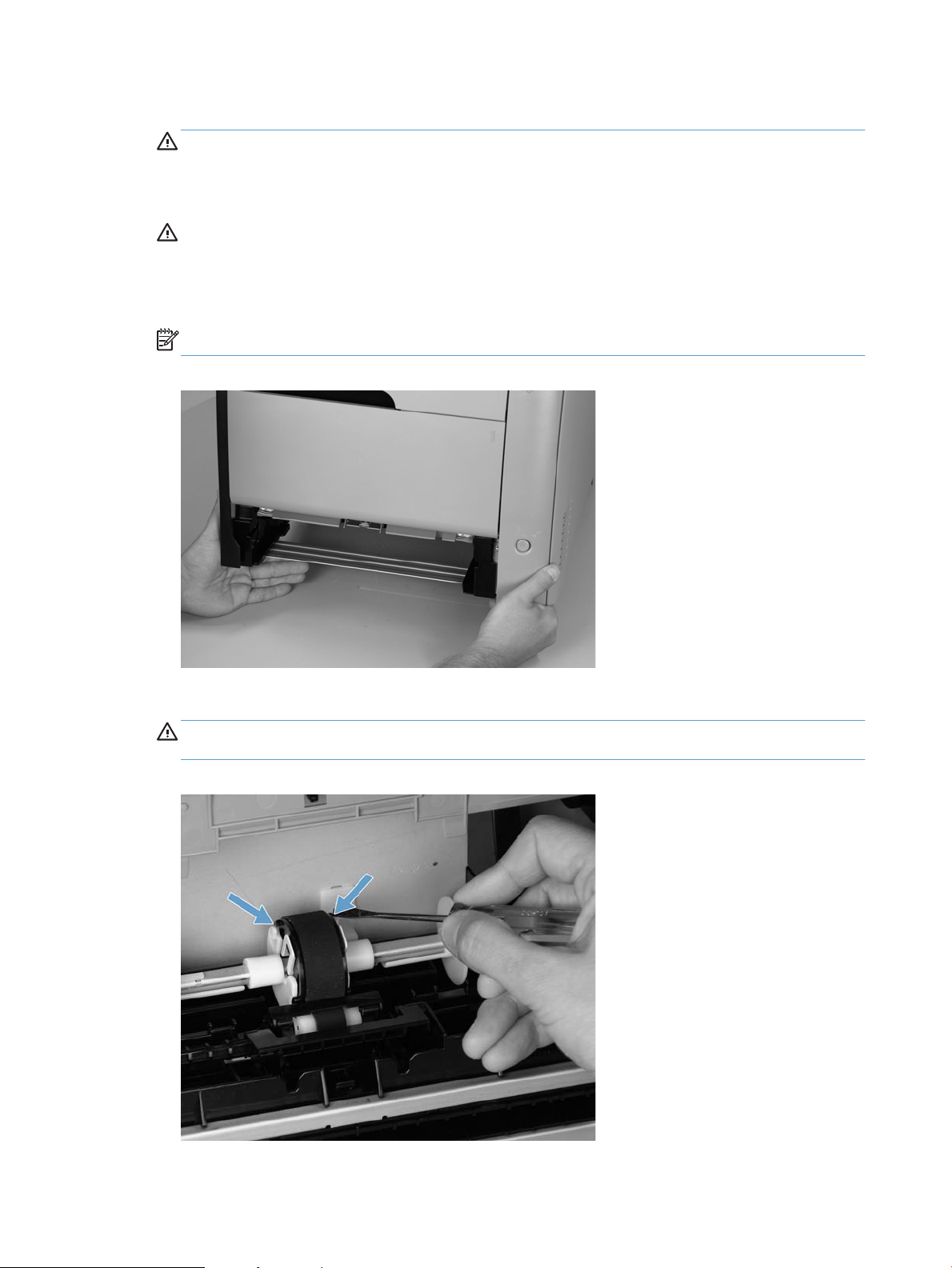
2. Carefully raise the front of the product.
WARNING! Do not place the product face-up resting on the rear cover and rear door unless you have
removed all toner cartridges. Excess toner might enter the laser/scanner assembly and contaminate
the mirrors, causing print-quality problems. The laser/scanner is not a FRU. If the laser/scanner mirrors
are contaminated, the entire product must be replaced.
CAUTION: The document feeder and scanner cover are not captive and can open suddenly when the
product is placed front-side face up. Always support the document feeder and scanner cover before
placing the product front-side face up.
Do not lift the product grasping the front door and Tray 2 cavity.
NOTE: The roller is located inside the tray cavity.
Figure 1-2 Raise the front of the product
3. Use a precision slotted (flat head) screwdriver to release two locking tabs and remove the pickup roller.
CAUTION: Do not touch the spongy roller surface unless you are going to replace the roller. Skin oils
on the roller can cause paper pickup problems.
Figure 1-3 Remove the pickup roller
10 Chapter 1 Removal and replacement ENWW
Page 24
Separation roller (Trays 2 or 3)
CAUTION: Avoid touching the spongy roller surface unless you are going to replace the roller. Skin oils on
the roller can cause paper pickup problems.
1. Remove Tray 2 (if installed), and then carefully raise the front of the product.
WARNING! Do not place the product face-up resting on the rear cover and rear door. Excess toner
might enter the laser/scanner assembly and contaminate the mirrors, causing print-quality problems.
The laser/scanner is not a FRU. If the laser/scanner mirrors are contaminated, the entire product must
be replaced.
CAUTION: Do not lift the product grasping the front door and Tray 2 cavity.
NOTE: The roller is located inside the tray cavity.
Figure 1-4 Remove the pickup roller (1 of 3)
2. Shift the cover to one side and pull it over the shaft, then slide the cover the other way to slide it off the
shaft and remove it.
Figure 1-5 Remove the separation roller (2 of 3)
ENWW Removal and replacement procedures 11
Page 25
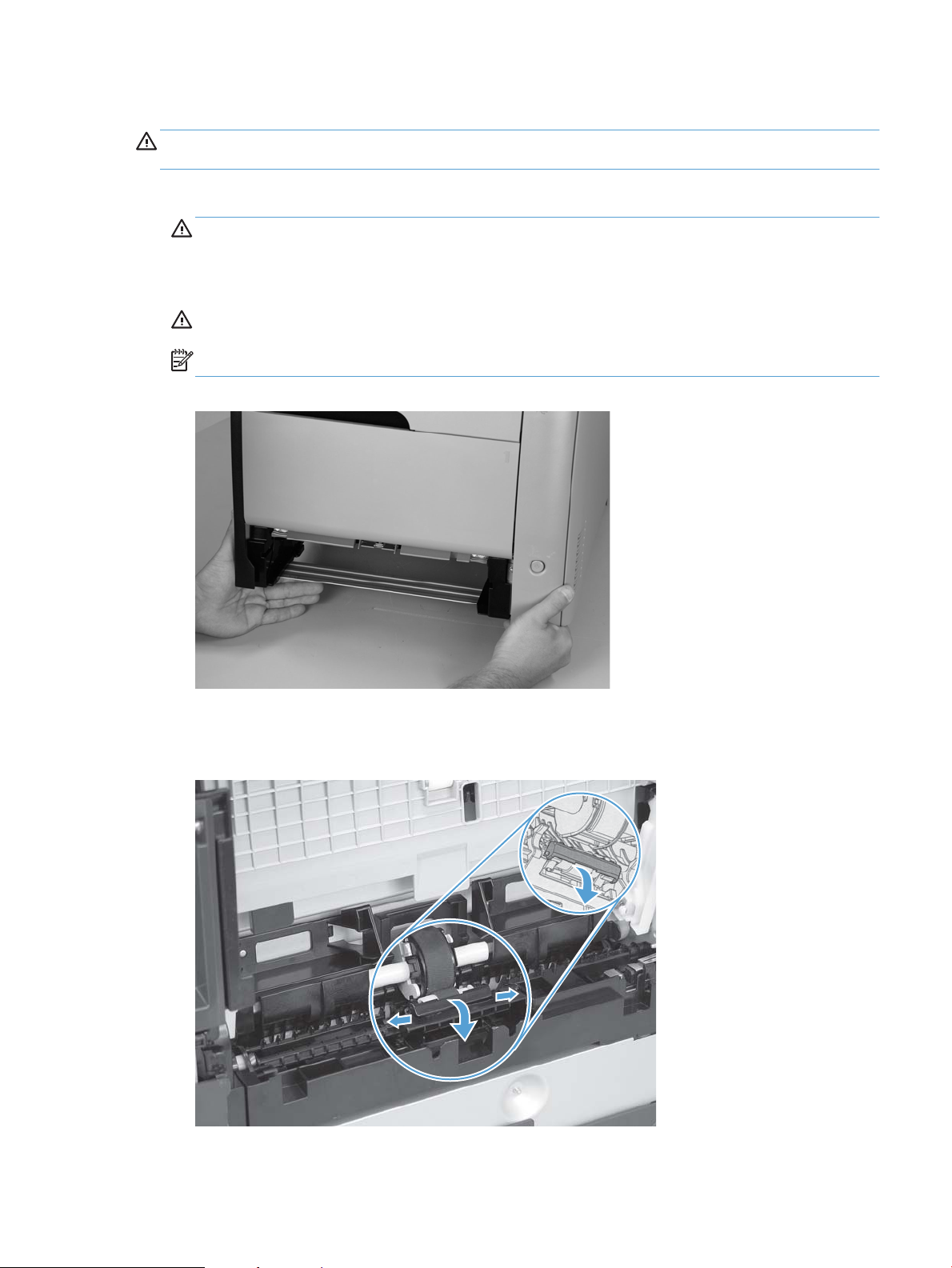
3. Wedge a small precision slotted (flat head) screwdriver under the left side of the roller holder to release
and remove the separation roller.
Figure 1-6 Remove the separation roller (3 of 3)
Reinstall the separation roller
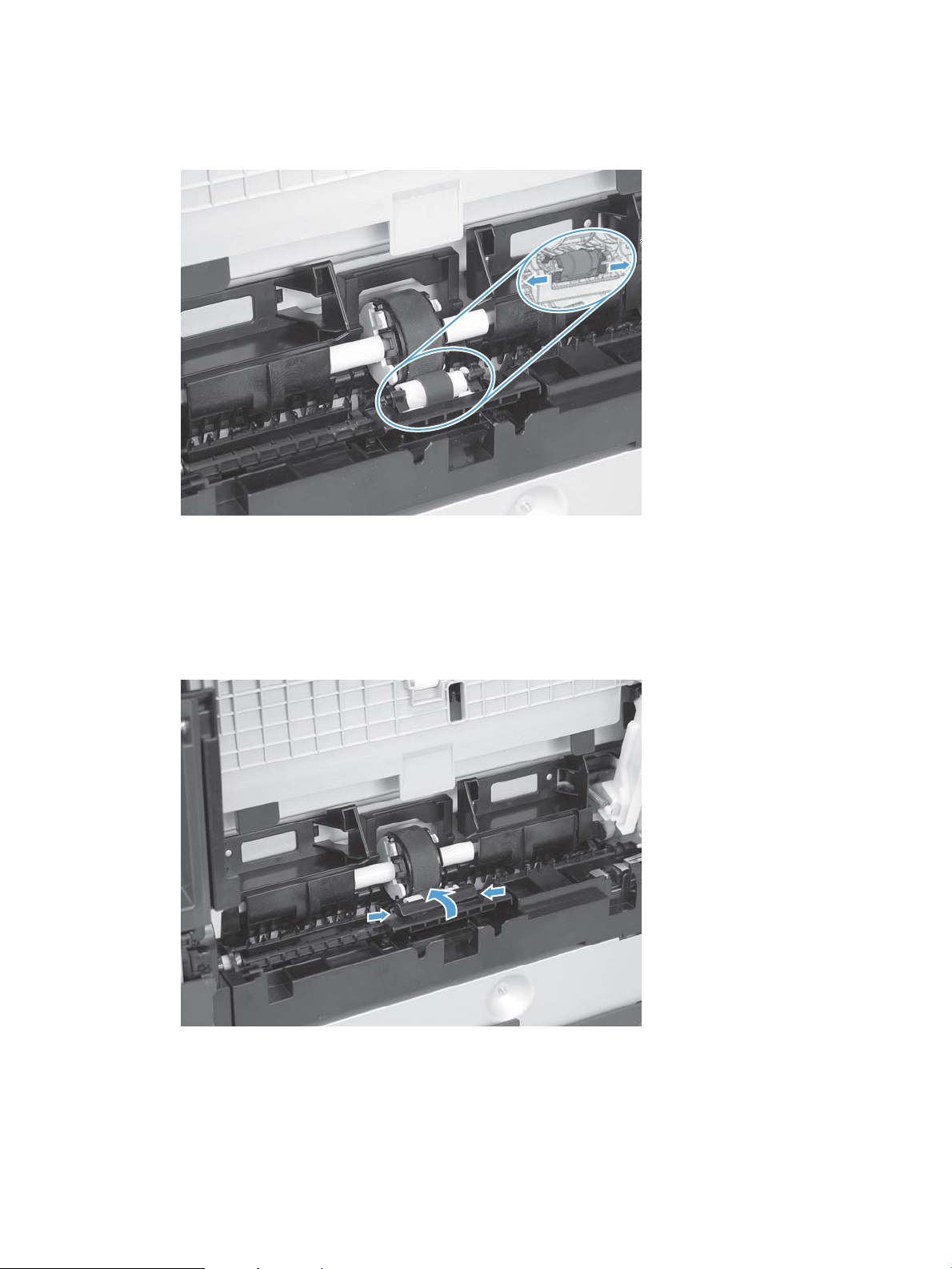
1. Install the replacement separation roller.
2. Reinstall the separation roller cover on the locking pins, and then rotate it toward the roller until you
hear it snap into place.
Figure 1-7 Reinstall the separation roller
12 Chapter 1 Removal and replacement ENWW
Page 26
Document feeder pickup roller assembly
CAUTION: Skin oils on the roller can cause paper pickup problems. Wash your hands before handling the
assembly.
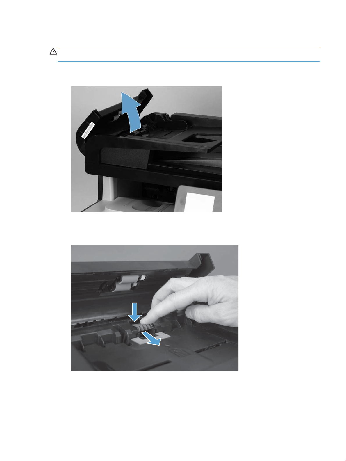
1. Open the jam-access cover.
Figure 1-8 Open the jam-access cover
2. Locate the separation pad at the end of the document feeder input tray, press down on the pad, and
then slide the pad toward the input tray to remove it from the assembly.
Figure 1-9 Remove the document feeder pickup roller assembly
ENWW Removal and replacement procedures 13
Page 27
Pickup roller and separation pad (Tray 1)
The roller must be rotated into the service position to remove it.
CAUTION: Avoid touching the spongy roller surface unless you are going to replace the roller. Skin oils on
the roller can cause paper pickup problems.
NOTE: Always replace the separation pad when replacing the pickup roller.
1. Turn the product on, and wait for it to reach the Ready state. Perform the following steps to rotate the
roller to the service position.
NOTE: If you have removed Tray 2 to service the product, reinstall the tray before turning the power
on.
TIP: The following steps rotate the engine pickup roller and the Tray 1 pickup roller into the service
position.
a. Open the 2ndary service menu. See Accessing the 2ndary service menu on page 4
b. Use the arrow buttons to select Pick Roller, and then press the OK button.
Touch the OK button again to confirm that you want the roller to rotate.
c. Listen for the roller to rotate. When the roller is done rotating, unplug the power cable.
NOTE: Failure to unplug the product at this point will result in the roller being in the incorrect
position for the repair procedure.
d. Remove Tray 2.
e. Perform the remaining steps in this procedure to remove the roller. After replacing the roller, plug
the power cable into the product, and then use the power button to turn the power on.
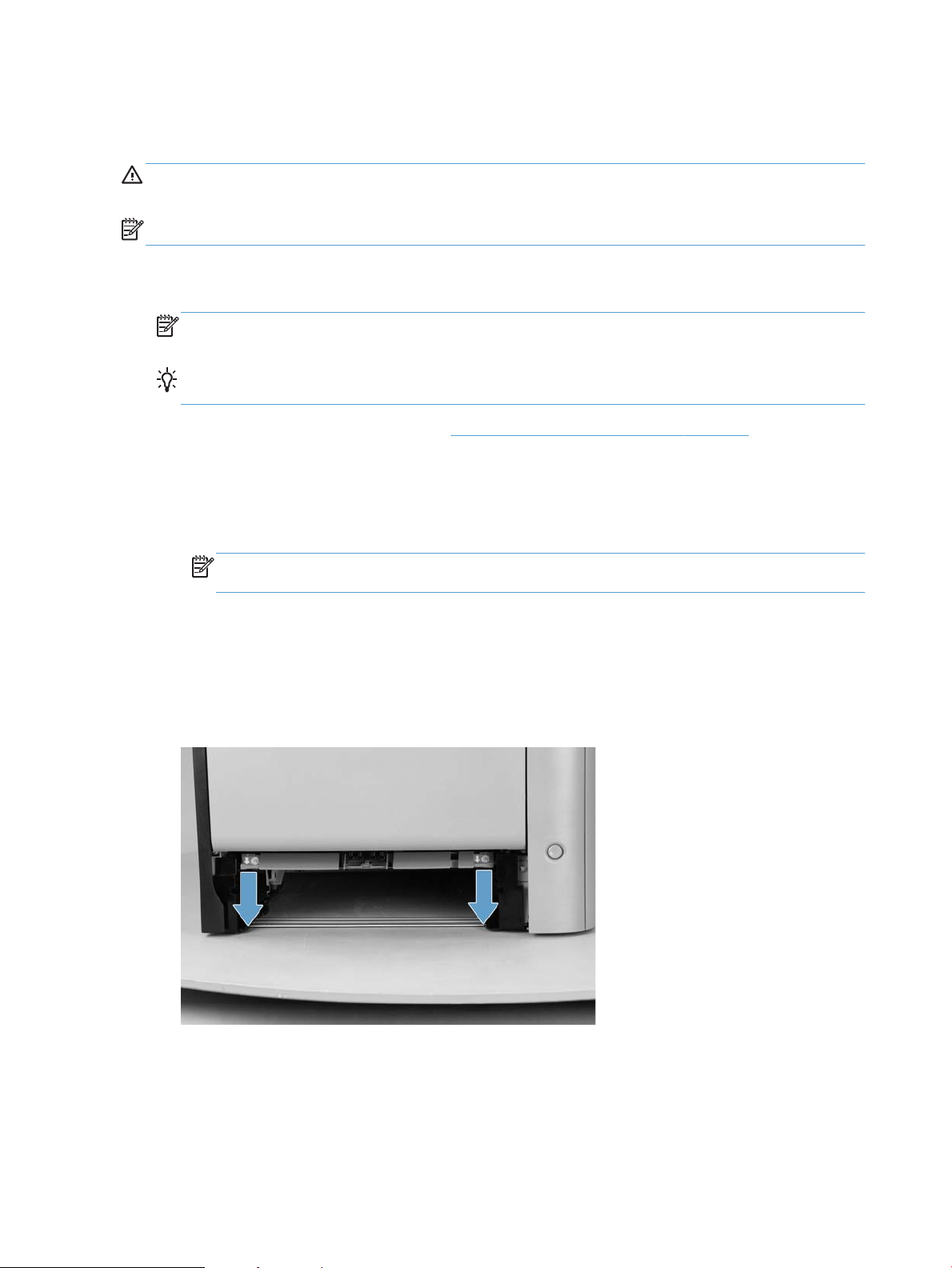
2. Lower the Tray 1 paper pickup assembly by pushing down on the edges of the assembly.
Figure 1-10 Remove the Tray 1 pickup roller (1 of 3)
14 Chapter 1 Removal and replacement ENWW
Page 28
3. Carefully raise the front of the product.
WARNING! Do not place the product face-up resting on the rear cover and rear door. Excess toner
might enter the laser/scanner assembly and contaminate the mirrors, causing print-quality problems.
The laser/scanner is not a FRU. If the laser/scanner mirrors are contaminated, the entire product must
be replaced.
CAUTION: The document feeder and scanner cover are not captive and can open suddenly when the
product is placed front-side face up. Always support the document feeder and scanner cover before
placing the product front-side face up.
CAUTION: Do not lift the product grasping the front door and Tray 2 cavity.
Figure 1-11 Raise the front of the product
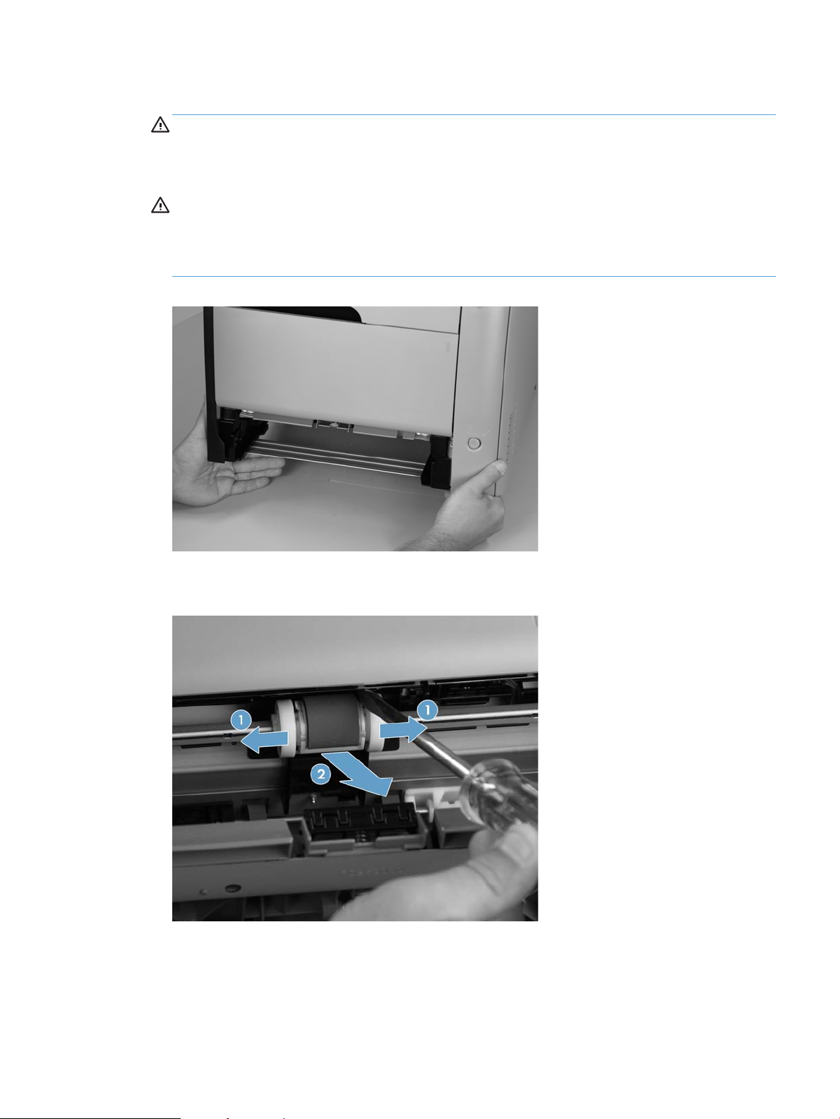
4. Release two tabs, and then rotate the roller away from the product to remove it.
Figure 1-12 Remove the Tray 1 pickup roller (3 of 3)
ENWW Removal and replacement procedures 15
Page 29
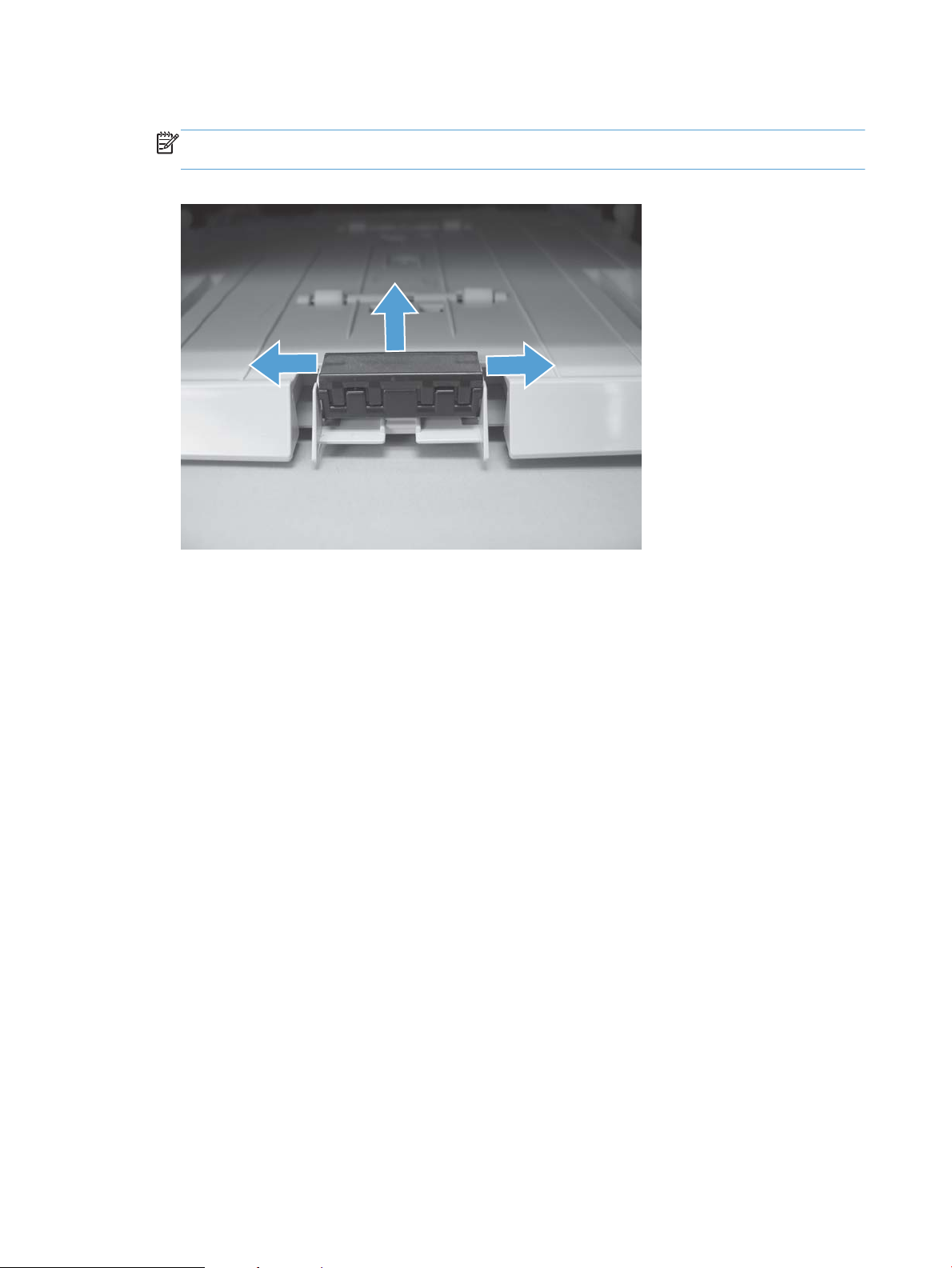
5. Release the retainer tabs, and then remove the separation pad from the base.
NOTE: The separation pad base can easily be dislodged when the pad is removed. If the base is
dislodged, do not loose the spring under the base (it is not captive).
Figure 1-13 Remove the Tray 1 separation pad
16 Chapter 1 Removal and replacement ENWW
Page 30
Scanner and document feeder
Scanner assembly
1. Remove the right cover. See Right cover on page 25.
2. Disconnect one ground cable (callout 1), one connector (callout 2), and three FFCs (callout 3).
NOTE: Use a small slotted (flat head) screwdriver to release the ferrite and expose the FFC.
WARNING! The ferrite and cable are fragile. Take care to not damage them when releasing the ferrite.
Figure 1-14 Disconnect the ground cable, connector, and FFCs
3. Remove four screws (callout 1).
Figure 1-15 Remove four screws
ENWW Removal and replacement procedures 17
Page 31

4. Slightly lift up the back of the scanner, and then slide it toward the front of the product.
Figure 1-16 Lift and slide the scanner assembly
5. Lift the scanner straight up and off of the product.
Figure 1-17 Lift the scanner up and off the product
Document feeder
Remove the scanner cable cover
Before proceeding, remove the following:
●
Right cover.
●
Scanner assembly/ADF.
18 Chapter 1 Removal and replacement ENWW
Page 32

1. Turn the scanner assembly/ADF over.
Figure 1-18 Turn the scanner assembly over
ENWW Removal and replacement procedures 19
Page 33

2. Use a small slotted (flat head) screw driver to remove three screws, then remove the cable cover.
Figure 1-19 Remove three screws, then remove the cable cover
Figure 1-20 Remove three screws, then remove the cable cover
20 Chapter 1 Removal and replacement ENWW
Page 34

3. Release the cables from the cable guides.
Figure 1-21 Release the cables
Remove the document feeder
NOTE: After removing the document feeder assembly, place it on a clean, dry, and smooth surface. Use a
T10 screwdriver to remove the screws.
▲
Use a small slotted (flat head) screwdriver to release two tabs (callout 1) on the hinges, and then pull
the document feeder straight up and off (callout 2) to remove it.
TIP: Push the screwdriver down into the hinge wells to release the tabs.
Figure 1-22 Remove the document feeder assembly
ENWW Removal and replacement procedures 21
Page 35

Reinstall the document feeder
After replacing the document feeder, perform E-duplex calibration to make sure that the formatter and ADF
are calibrated correctly.
1. To reinstall the document feeder, perform the steps in Remove the document feeder in reverse.
NOTE: The cables connecting the document feeder to the scanner assembly are fragile. Be careful to
not damage the cables while reinstalling the document feeder.
2. Power off the device, then turn it back on.
3. Cut down two plain sheets of white paper to measure 220 mm by 140 mm (8.65 in x 5.5 in) and place
them in the ADF, long edge first.
NOTE: The required sheet dimensions can be achieved by turning a sheet of Letter or A4 size paper on
its side.
4. Open the 2ndary service menu. See Accessing the 2ndary service menu on page 4
5. Scroll down until eDuplexCalibration displays on the touchscreen, touch to select it, then touch OK .
6. The ADF pulls the paper into the product and the calibration begins. Although the process appears to be
complete, continue to wait for 70 seconds after the sheets have been scanned before proceeding.
7. To exit the 2ndary Service menu, go to the Home screen, then simultaneously touch the hidden Left
Arrow Left Arrow and Cancel Cancel icons.
8. Print a 2-sided copy and confirm that the output is acceptable.
Covers and doors
Print-cartridge drawer
1. Open the front door.
22 Chapter 1 Removal and replacement ENWW
Page 36

2. Partially pull out the print-cartridge drawer, and then use a small flat blade screwdriver to release one
1
tab (callout 1) on the left side of the product.
Figure 1-23 Remove the print-cartridge drawer (1 of 3)
3. Carefully rotate the print-cartridge drawer toward the right side of the product to release it.
Figure 1-24 Remove the print-cartridge drawer (2 of 3)
ENWW Removal and replacement procedures 23
Page 37

4. Pull the print-cartridge drawer out of the product to remove it.
Figure 1-25 Remove the print-cartridge drawer (3 of 3)
24 Chapter 1 Removal and replacement ENWW
Page 38

Right cover
1
1. Open the rear door.
2. Remove three screws (callout 1).
Figure 1-26 Remove the right cover (1 of 2)
3. Slide the right cover toward the back of the product and remove the cover.
Figure 1-27 Remove the right cover (2 of 2)
ENWW Removal and replacement procedures 25
Page 39

Right-front cover and power button
1
1. Remove the right cover. See Right cover on page 25.
2. Disconnect the USB PCA connector from the formatter PCA (callout 1), and then release the wire from
the retainer (callout 2).
3. Open the front door, and then remove three screws (callout 1).
26 Chapter 1 Removal and replacement ENWW
Page 40

4. Remove one screw and retainer (callout 1), and then remove two screws (callout 2).
5. Slide the cover slightly toward the right to release three tabs (callout 1), and then remove the cover.
ENWW Removal and replacement procedures 27
Page 41

Rear-upper cover
1
1. Open the rear door.
2. Remove two screws (callout 1).
Figure 1-28 Remove the rear-upper cover (1 of 2)
3. Slightly separate the cover from the product, and then rotate the cover down and then away from the
product to remove it.
Figure 1-29 Remove the rear-upper cover (2 of 2)
28 Chapter 1 Removal and replacement ENWW
Page 42

Paper-feed guide assembly
1
1. Release one screw (callout 1).
Figure 1-30 Remove the feed assembly (1 of 2)
2. Remove the feed assembly.
TIP: When the feed assembly is correctly reinstalled, the assembly will be able to move in relation to
the door. It should not be secured firmly to the door.
Figure 1-31 Remove the feed assembly (2 of 2)
ENWW Removal and replacement procedures 29
Page 43

Rear door
1. Open the rear door.
2. Use the green handle to close the duplex-feed assembly.
Figure 1-32 Close the duplex-feed assembly
3. Remove two screws (callout 1).
NOTE: Before you remove the rear door, take note of the mounting tabs on the door (callout 2).
Figure 1-33 Remove two screws
30 Chapter 1 Removal and replacement ENWW
Page 44

4. Slide the door away from the product to release two tabs, and then remove the door.
Figure 1-34 Remove the rear door
ENWW Removal and replacement procedures 31
Page 45

Rear-lower cover and rear-door links
Before proceeding, remove the following components:
●
Right cover. See Right cover on page 25.
●
Rear door. See Rear door on page 30.
●
Rear upper cover. See Rear-upper cover on page 28.
Remove the rear-lower cover and rear-door links
1. Use a pair of needle-nose pliers to release two tabs, and then remove the rear-door link cap. Repeat
this step for the remaining rear-door link cap.
Figure 1-35 Remove the rear- lower cover and rear-door links (1 of 6)
32 Chapter 1 Removal and replacement ENWW
Page 46

2. Open the duplex-feed assembly, release one tab (callout 1), and then slightly separate the cover from
1
1
the product.
Figure 1-36 Remove the rear-lower cover and rear-door links (2 of 6)
3. Release one tab (callout 1) and slightly separate the cover from the product.
Figure 1-37 Remove the rear-lower cover and rear-door links (3 of 6)
ENWW Removal and replacement procedures 33
Page 47

4. Close the duplex assembly, and then lift up on one side of the cover, and then the other side of the
cover to release it.
Figure 1-38 Remove the rear-lower cover and link-guides (4 of 6)
5. Slightly lift up the rear-door rib assembly, and then carefully slide the cover away from the product to
remove it.
Figure 1-39 Remove the rear-lower cover and link-guides (5 of 6)
34 Chapter 1 Removal and replacement ENWW
Page 48

6. Rotate the rear-door link until the slot in the link aligns with the tap on the link-hinge pin, and then
remove the rear-door link. Repeat this step for the remaining rear-door link.
NOTE: If you are installing a replacement rear-lower cover, remove the rear-door links from the
discarded cover, and then install them on the replacement cover.
Figure 1-40 Remove the rear-lower cover and rear-door links (6 of 6)
ENWW Removal and replacement procedures 35
Page 49

Rear-door rib assembly
Before proceeding, remove the following components:
●
Right cover. See Right cover on page 25.
●
Rear door. See Rear door on page 30.
●
Rear upper cover. See Rear-upper cover on page 28.
●
Rear-lower cover. See Rear-lower cover and rear-door links on page 32.
Remove the rear-door rib assembly
NOTE: The duplex fan (FM2) is a component of the rear-door rib assembly.
1. Slide the rear rib assembly to the left, lift the door gently, and then rotate it away from the product
slightly.
Figure 1-41 Remove the rear-door rib assembly (1 of 3)
36 Chapter 1 Removal and replacement ENWW
Page 50

2. Slide the PCA loose, then remove the third connector from the right with red, yellow, and black wires.
TIP: The PCA can be dislodged when disconnecting the connector. To secure the PCA, carefully push it
towards the inside of the product to clear the mounting tabs near the rib assembly (callout 2 shows the
PCA correctly positioned under the tabs). Slide the PCA towards the rib assembly to position the edge of
the PCA under the mounting tabs.
Figure 1-42 Remove the rear-door rib assembly (2 of 3)
3. Slide the assembly toward the power cable side of the product to release the hinge pin.
Figure 1-43 Remove the rear-door rib assembly (2 of 3)
ENWW Removal and replacement procedures 37
Page 51

4. Remove the assembly.
Figure 1-44 Remove the rear-door rib assembly (3 of 3)
38 Chapter 1 Removal and replacement ENWW
Page 52

Control panel and right-arm mount
1. Remove the Right cover. See Right cover on page 25.
2. Remove the wireless PCA.
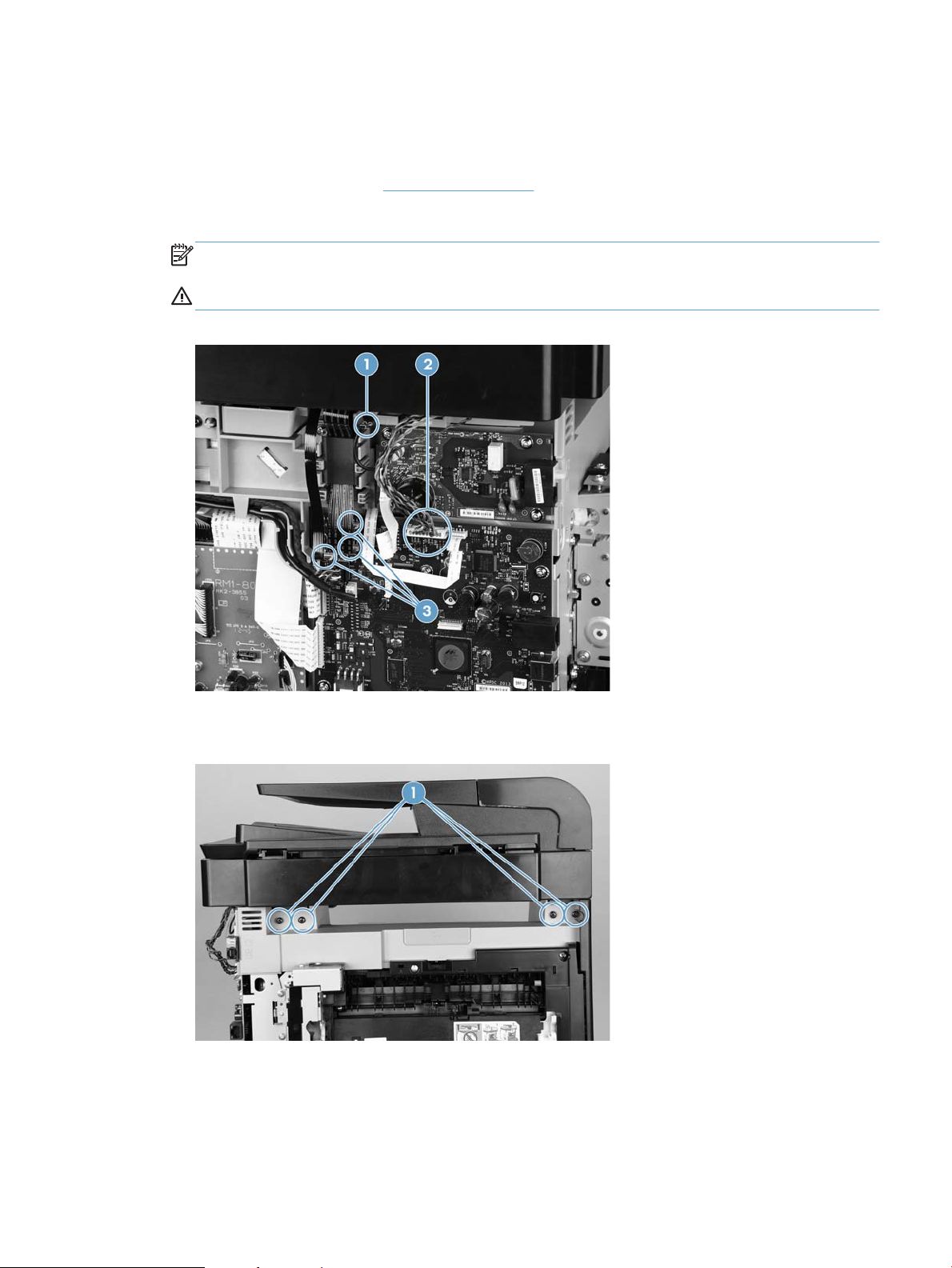
3. Disconnect two FFCs (callout 2) and two connectors, detach the USB PCA connector in the retainer, then
loosen the ferrite from the control panel mount (callout 1).
Figure 1-45 Disconnect FFCs and connectors and loosen ferrite
4. Remove four screws (callout 1) and disconnect the ground wire (callout 2).
Figure 1-46 Remove four screws and disconnect the ground wire
ENWW Removal and replacement procedures 39
Page 53

5. Slide the control panel right-arm mount to the right to remove it from the scanner chassis.
Figure 1-47 Remove the right-arm mount
Reinstall the control panel and right-arm mount
1. Install the wireless card into the new control panel.
2. Slide the control panel right-arm mount assembly into the mounting points on the scanner chassis.
3. Install four screws (callout 1) and attach the grounding wire (callout 2).
Figure 1-48 Install four screws and connect the ground wire
40 Chapter 1 Removal and replacement ENWW
Page 54

4. Replace two FFCs (callout 2), two connectors, and the PCA connector, then replace the ferrite (callout 1).
Figure 1-49 Connect FFCs and connectors and replace ferrite
ENWW Removal and replacement procedures 41
Page 55

Upper-cover assembly
Before proceeding, remove the following components:
●
Right cover. See Right cover on page 25.
●
Scanner assembly. See Scanner assembly on page 17.
●
Rear upper cover. See Rear-upper cover on page 28.
●
Control panel and right-arm mount. See Control panel and right-arm mount on page 39.
●
Right-front cover and power button. See Right-front cover and power button on page 26.
Remove the upper-cover assembly
1. Remove four screws (callout 1).
Figure 1-50 Remove four screws
2. Slightly raise the back of the cover up and off of the product.
Figure 1-51 Raise the back of the cover up and off the product
42 Chapter 1 Removal and replacement ENWW
Page 56

3. Slide the cover toward the back of the product to remove it.
1
Figure 1-52 Remove the upper-cover assembly
Reinstall the upper-cover assembly
1. Position the upper-cover so that the front-left corner of the upper cover engages the left-side cover
(callout 1).
Figure 1-53 Reinstall the upper-cover assembly (1 of 3)
ENWW Removal and replacement procedures 43
Page 57

2. Slightly push the cover toward the front of the product to engage the front-locking tabs (callout 1) with
1
the holes in the chassis.
NOTE: Make sure that the right-front edge of the upper cover (where the product right-front cover will
be installed) is correctly positioned on the chassis.
Figure 1-54 Reinstall the upper-cover assembly (2 of 3)
3. Carefully pry the right-rear corner of the upper cover away from the product until the cover fits over the
chassis.
Lower the cover onto the product.
Figure 1-55 Reinstall the upper-cover assembly (3 of 3)
44 Chapter 1 Removal and replacement ENWW
Page 58

Left cover
1
Before proceeding, remove the following components:
●
Right cover. See Right cover on page 25.
●
Scanner assembly. See Scanner assembly on page 17.
●
Rear-lower cover. See Rear-lower cover and rear-door links on page 32.
●
Upper-cover assembly. See Upper-cover assembly on page 42.
Remove the left cover
1. Remove one screw (callout 1).
Figure 1-56 Remove the left cover (1 of 3)
ENWW Removal and replacement procedures 45
Page 59

2. Slightly lift up on the cover, and then rotate the top of the cover away from the product.
Figure 1-57 Remove the left cover (2 of 3)
3. Remove the cover.
Figure 1-58 Remove the left cover (3 of 3)
46 Chapter 1 Removal and replacement ENWW
Page 60

Reinstall the left cover
1
2
1
2
1. When you reinstall the left cover, make sure that the slot in the cover (callout 1) aligns with the tab
(callout 2) on the product.
Figure 1-59 Reinstall the left cover (1 of 2)
2. When you reinstall the left cover, make sure that the pin on the cover (callout 1) aligns with the slot
(callout 2) in the product.
Figure 1-60 Reinstall the left cover (2 of 2)
ENWW Removal and replacement procedures 47
Page 61

Front-door assembly
Before proceeding, remove the following components:
●
Print-cartridge drawer. See Print-cartridge drawer on page 22.
●
Right cover. See Right cover on page 25.
●
Scanner assembly. See Scanner assembly on page 17.
●
Rear-upper cover. See Rear-upper cover on page 28.
●
Rear door. See Rear door on page 30.
●
Rear-lower cover. See Rear-lower cover and rear-door links on page 32.
●
Upper-cover assembly. See Upper-cover assembly on page 42.
●
Left cover. See Left cover on page 45.
●
Right-front cover. See Right-front cover and power button on page 26.
Remove the front-door assembly
1. Locate the front-door pin on the left-side door link.
Figure 1-61 Remove the front-door assembly (1 of 10)
48 Chapter 1 Removal and replacement ENWW
Page 62

2. Use a precision point (flat head) screwdriver to push the left-side metallic door pin out of the link.
NOTE: A precision point screwdriver is required to release the front door pins. The width of the blade
must be 2 mm (0.08 in) or less to be able to push the door pins out of the mounting holes.
Figure 1-62 Remove the front-door assembly (2 of 10)
3. Use a precision point (flat head) screwdriver to push the right-side metallic door pin out of the link.
NOTE: A precision point screwdriver is required to release the front door pins. The width of the blade
must be 2 mm (0.08 in) or less to be able to push the door pins out of the mounting holes.
Figure 1-63 Remove the front-door assembly (3 of 10)
ENWW Removal and replacement procedures 49
Page 63

4. Remove two screws (callout 1) and then separate the door bushing (callout 2) from the chassis.
Figure 1-64 Remove the front-door assembly (4 of 10)
5. Release the bushing from the door-retainer link (callout 1).
Figure 1-65 Remove the front-door assembly (5 of 10)
50 Chapter 1 Removal and replacement ENWW
Page 64

6. Support the door assembly, and carefully release the pin on the right-side link.
Figure 1-66 Remove the front-door assembly (6 of 10)
7. Support the door assembly, and carefully release the upper pin on the left-side link.
Figure 1-67 Remove the front-door assembly (7 of 10)
ENWW Removal and replacement procedures 51
Page 65

8. Push the black-plastic arm into the product.
Figure 1-68 Remove the front-door assembly (8 of 10)
9. Support the door assembly, and carefully release the lower pin on the left-side link.
Figure 1-69 Remove the front-door assembly (9 of 10)
52 Chapter 1 Removal and replacement ENWW
Page 66

10. Remove the front-door assembly.
Figure 1-70 Remove the front-door assembly (10 of 10)
ENWW Removal and replacement procedures 53
Page 67

Internal assemblies
1
Intermediate transfer belt (ITB)
1. Remove the print-cartridge drawer. See Print-cartridge drawer on page 22.
2. Open the front door, and then remove two screws (callout 1).
Figure 1-71 Remove the ITB (1 of 6)
3. Carefully rotate the color-misregistration sensor away from the ITB.
CAUTION: The sensor is still attached to the product and cannot be completely removed.
Figure 1-72 Remove the ITB (2 of 6)
54 Chapter 1 Removal and replacement ENWW
Page 68

4. Disconnect one connector (callout 1).
1
Figure 1-73 Remove the ITB (3 of 6)
5. Carefully lift up on the front of the ITB to release it.
CAUTION: Wear gloves when handling the ITB, and avoid touching the black plastic transfer belt. Skin
oils on the belt might cause print-quality problems. Lift the ITB as shown below, by using the hardplastic edges of the ITB.
Figure 1-74 Remove the ITB (4 of 6)
ENWW Removal and replacement procedures 55
Page 69

6. Open the rear door, and carefully lift up on the sheet-metal portion (callout 1) of the ITB to release it.
1
CAUTION: Avoid touching the black plastic transfer belt. Skin oils on the belt might cause print-quality
problems.
NOTE: You might need to reach in through the front door and support the front portion of the ITB to
keep it from falling back into place as you perform this step.
Figure 1-75 Remove the ITB (5 of 6)
7. Carefully pull the ITB straight out of the product to remove it.
CAUTION: Wear gloves when handling the ITB, and avoid touching the black plastic transfer belt. Skin
oils on the belt might cause print-quality problems. Handle the ITB as shown below.
Figure 1-76 Remove the ITB (6 of 6)
56 Chapter 1 Removal and replacement ENWW
Page 70

Reinstall the ITB
Use this procedure to reinstall the ITB and then verify that the ITB is correctly reinstalled.
1. Press the ITB back on the springs to fully seat it into position. To seat the ITB correctly, push in the
2. Use the control panel to print the diagnostics pages.
3. Verify that rows one through four, columns A through I (callout 1) contain hexadecimal numbers.
spring-loaded gear on the engine side.
If these rows and columns are all zero, ensure that the calibration sensor was correctly reinstalled. The
sensor must be correctly positioned and fit securely against the chassis before the mounting screws are
installed. See
Figure 1-77 Diagnostic page
1 and 2.
ENWW Removal and replacement procedures 57
Page 71

Drum motor (M1) and developer motor (M2)
1
2
3
This procedure can be used to remove the drum motor (M1) or the developer motor (M2). HP does not
recommend removing both of the motors at the same time.
1. Remove the right cover. See Right cover on page 25.
2. Disconnect one connector (callout 1) for motor M1 or motor M2.
NOTE: The drum motor (callout 2) is motor M1. The developer motor (callout 3) is motor M2.
Figure 1-78 Remove motor M1 and motor M2 (1 of 6)
58 Chapter 1 Removal and replacement ENWW
Page 72

3. Remove one screw (callout 1), and then remove the black-plastic retainer (callout 2).
1
2
NOTE: There is a small clip—the clip is used to activate the engine test button—attached to the
retainer that can be easily dislodged when the retainer is removed. Do not lose this clip when handling
the retainer.
Figure 1-79 Remove motor M1 and motor M2 (2 of 6)
ENWW Removal and replacement procedures 59
Page 73

4. Release the wire harnesses from the retainer (callout 1).
1
NOTE: One of the wire harnesses—behind the drum motor wire harness—is difficult to release from
the retainer. Be careful to not damage this wire harness when releasing it.
TIP: Additional connectors might need to be disconnected to release the wire harnesses from the
retainer.
Figure 1-80 Remove motor M1 and motor M2 (3 of 6)
60 Chapter 1 Removal and replacement ENWW
Page 74

5. Release one tab (callout 1).
1
Figure 1-81 Remove motor M1 and motor M2 (4 of 6)
6. Rotate the top of the retainer away from the chassis, and then lift it up to remove it.
Figure 1-82 Remove motor M1 and motor M2 (5 of 6)
ENWW Removal and replacement procedures 61
Page 75

7. Remove three screws (callout 1) to remove motor M1, or remove three screws (callout 2) to remove
1
2
motor M2.
Figure 1-83 Remove motor M1 and motor M2 (6 of 6)
62 Chapter 1 Removal and replacement ENWW
Page 76

Reinstall the drum motor (M1) and developer motor (M2)
When the motor wire harness retainer is reinstalled, the two tabs at the bottom of the retainer must be
positioned behind the retainer on the low-voltage power supply. The tab at the side of motor wire harness
retainer must be positioned behind the PCA next to motor M2.
Figure 1-84 Reinstall the motor M1 and motor M2 wire-harness retainer
ENWW Removal and replacement procedures 63
Page 77

Intermediate PCA
1
1
1. Remove the right cover. See Right cover on page 25.
2. Disconnect all of the connectors and one FFC (callout 1) on the PCA.
Figure 1-85 Remove the Intermediate PCA (1 of 2)
3. Remove three screws (callout 1) , and then remove the intermediate PCA.
Figure 1-86 Remove the Intermediate PCA (2 of 2)
64 Chapter 1 Removal and replacement ENWW
Page 78

Formatter PCA
WARNING! Do not install a replacement formatter PCA and DC controller PCA at the same time.
The formatter PCA and the DC controller PCA store important product configuration information (NVRAM
data) that is lost if both PCAs are replaced at the same time. When the product power is turned on, the DC
controller restores the NVRAM data on the replacement formatter.
Replacing both the formatter and the DC controller at the same time will result in severe print-quality
problems.
NOTE: The base model does not have a fax card installed.
Replacing the formatter PCA before the DC controller PCA
Use the following procedure if you need to install a replacement formatter PCA and a replacement DC
controller.
NOTE: If you are only installing a replacement formatter PCA, go to Remove the formatter PCA
on page 65.
1. Install a replacement formatter PCA.
2. Turn the product on, and wait for the print-cartridge volume indicators to appear on the control-panel
display.
NOTE: This allows important product information to be written to the replacement formatter PCA.
3. Turn the product off.
4. Install a replacement DC controller. See DC controller PCA on page 69.
5. Turn the product on.
Remove the formatter PCA
CAUTION: Do not bend or fold the flat flexible cables (FFCs) during removal or installation. Also, do not
straighten pre-folds in the FFCs. You must make sure that all FFCs are fully seated in their connectors. Failure
to fully seat an FFC into a connector can cause a short circuit in a PCA.
Some parts are sensitive to electrostatic discharge (ESD). Always perform service work at an ESD-
protected workstation or mat. If an ESD workstation or mat is not available, ground yourself by touching the
sheet-metal chassis before touching an ESD-sensitive part.
NOTE: The base model does not have a fax PCA.
1. Remove the right cover. See Right cover on page 25.
ENWW Removal and replacement procedures 65
Page 79

2. Disconnect 11 connectors.
Figure 1-87 Remove the formatter PCA (1 of 2)
3. Remove four screws, and then remove the formatter PCA.
Figure 1-88 Remove the formatter PCA (2 of 2)
Fax PCA
1. Remove the right cover. See Right cover on page 25
66 Chapter 1 Removal and replacement ENWW
Page 80

2. Remove four screws (callout 1) and one connector (callout 2).
NOTE: The base model does not have a fax PCA.
Figure 1-89 Remove the fax PCA
3. Remove the fax PCA.
ENWW Removal and replacement procedures 67
Page 81

Wireless PCA
1. Remove the right cover. See Right cover on page 25
2. Remove one screw (callout 1). Disconnect one connector (callout 2) at the formatter PCA.
Figure 1-90 Remove the wireless PCA
3. Remove the wireless PCA.
68 Chapter 1 Removal and replacement ENWW
Page 82

DC controller PCA
WARNING! Do not install a replacement formatter PCA and a replacement DC controller PCA at the same
time.
The formatter PCA and the DC controller PCA store important product configuration information (NVRAM
data) that is lost if both PCAs are replaced at the same time. When the product power is turned on, the
formatter restores the NVRAM data to a replacement DC controller.
Replacing both the DC controller and the formatter at the same time will result in severe print-quality
problems.
Replacing the DC controller PCA before the formatter PCA
Use the following procedure if you need to install a replacement DC controller and a replacement formatter
PCA.
1. Install a replacement DC controller PCA.
2. Turn the product on, and wait for the print-cartridge volume indicators to appear on the control-panel
display.
NOTE: This allows important product information to be written to the replacement DC controller PCA.
3. Turn the product off.
4. Install a replacement formatter PCA. See Formatter PCA on page 65.
5. Turn the product on.
Before you proceed, remove the following components:
●
Right cover. See Right cover on page 25.
●
Scanner assembly. See Scanner assembly on page 17.
●
Upper cover. See Upper-cover assembly on page 42.
Remove the DC controller PCA
CAUTION: Do not bend or fold the flat flexible cables (FFCs) during removal or installation. Also, do not
straighten pre-folds in the FFCs. You must make sure that all FFCs are fully seated in their connectors. Failure
to fully seat an FFC into a connector can cause a short circuit in a PCA.
Some parts are sensitive to electrostatic discharge (ESD). Always perform service work at an ESD-
protected workstation or mat. If an ESD workstation or mat is not available, ground yourself by touching the
sheet-metal chassis before touching an ESD-sensitive part.
1. Disconnect all of the connectors.
NOTE: The DC controller is located along the top right of the product.
ENWW Removal and replacement procedures 69
Page 83

Figure 1-91 Remove the DC controller PCA (1 of 2)
2. Remove four screws (callout 1) and then remove the DC controller PCA.
Figure 1-92 Remove the DC controller PCA (2 of 2)
70 Chapter 1 Removal and replacement ENWW
Page 84

Fuser-motor assembly
2
1
Before proceeding, remove the following components:
●
Right cover. See Right cover on page 25.
●
Control panel and right-arm mount. See Control panel and right-arm mount on page 39.
●
Formatter and fax PCAs. See Formatter PCA on page 65.
●
Rear-upper cover. See Rear-upper cover on page 28.
Remove the fuser-motor assembly
1. Remove 5 screws (callout 1) and 3 screws (callout 2).
Figure 1-93 Remove the fuser-motor assembly (1 of 6)
ENWW Removal and replacement procedures 71
Page 85

2. Remove three screws (callout 1) and release the wire harness from the retainer. Remove the fan
1
1
assembly.
NOTE: The fan assembly is still attached to the product. Move the fan assembly off to one side.
Figure 1-94 Remove the fuser-motor assembly (2 of 6)
3. Release three tabs (callout 1), and then remove the retainer.
Figure 1-95 Remove the fuser-motor assembly (3 of 6)
72 Chapter 1 Removal and replacement ENWW
Page 86

4. Disconnect one connector (callout 1) and remove the wire harness from the retainer (callout 2).
2
1
13
Figure 1-96 Remove the fuser-motor assembly (4 of 6)
5. Remove three screws (callout 1), and then remove the fuser-motor assembly.
Figure 1-97 Remove the fuser-motor assembly (5 of 6)
ENWW Removal and replacement procedures 73
Page 87

6. Before you proceed, take note that the spring and the gears behind the fuser-motor assembly are not
2
1
captive.
CAUTION: Do not lose the spring or gears when you remove the fuser-motor assembly.
Figure 1-98 Remove the fuser-motor assembly (6 of 6)
Reinstall the fuser-motor assembly
Make sure that the fuser-motor assembly spring (callout 1) and gear pin (callout 2) are correctly positioned in
the hole and slot provided in the assembly mounting bracket. The assembly mounting bracket will fit flat
against the product chassis when the fuser-motor assembly is correctly installed.
Figure 1-99 Reinstall the fuser-motor assembly
74 Chapter 1 Removal and replacement ENWW
Page 88

High-voltage power-supply PCA
2
1
Before proceeding, remove the following components:
●
Right cover. See Right cover on page 25.
●
Scanner assembly. See Scanner assembly on page 17.
●
Rear door. See Rear door on page 30.
●
Rear-lower cover. See Rear-lower cover and rear-door links on page 32.
●
Upper-cover assembly. See Upper-cover assembly on page 42.
●
Left cover. See Left cover on page 45.
Remove the high-voltage power-supply PCA
1. Remove two screws (callout 1), and then remove the sheet-metal plate (callout 2).
Figure 1-100 Remove the high-voltage power-supply PCA (1 of 5)
ENWW Removal and replacement procedures 75
Page 89

2. Release six tabs (callout 1), and then remove the black-plastic cover.
1
1
Figure 1-101 Remove the high-voltage power-supply PCA (2 of 5)
3. Disconnect one FFC (callout 1) on the DC controller.
Figure 1-102 Remove the high-voltage power-supply PCA (3 of 5)
76 Chapter 1 Removal and replacement ENWW
Page 90

4. Disconnect one connector (callout 1), and then remove six screws (callout 2).
1
2
1
Figure 1-103 Remove the high-voltage power-supply PCA (4 of 5)
5. Release ten tabs (callout 1), and then remove the high-voltage power-supply PCA.
Figure 1-104 Remove the high-voltage power-supply PCA (5 of 5)
ENWW Removal and replacement procedures 77
Page 91

Color-misregistration sensor assembly
1
2
Before proceeding, remove the following components:
●
Print-cartridge drawer. See Print-cartridge drawer on page 22.
●
Right cover. See Right cover on page 25.
●
Scanner assembly. See Scanner assembly on page 17.
●
Rear-lower cover. See Rear-lower cover and rear-door links on page 32.
●
Upper-cover assembly. See Upper-cover assembly on page 42.
●
Left cover. See Left cover on page 45.
●
High-voltage power-supply PCA. See High-voltage power-supply PCA on page 75.
Remove the color-misregistration sensor assembly
1. Disconnect one connector (callout 1), and then release the wire harness from the guide (callout 2).
Figure 1-105 Remove the color-misregistration sensor assembly PCA (1 of 4)
78 Chapter 1 Removal and replacement ENWW
Page 92

2. Release the wire harness from the guide (callout 1).
1
2
1
NOTE: When you remove the sensor assembly later in this procedure, pass the connector and wire
harness through the hole in the chassis (callout 2).
Figure 1-106 Remove the color-misregistration sensor assembly PCA (2 of 4)
3. Remove two screws (callout 1).
Figure 1-107 Remove the color-misregistration sensor assembly PCA (3 of 4)
ENWW Removal and replacement procedures 79
Page 93

4. Carefully separate the sensor assembly (callout 1) from the product, pass the wire harness through the
hole in the chassis, and then remove the assembly.
NOTE: Pass the connector and wire harness through the hole in the chassis. See Figure 1-106 Remove
the color-misregistration sensor assembly PCA (2 of 4) on page 79.
Figure 1-108 Remove the color-misregistration sensor assembly PCA (4 of 4)
Reinstall the color-misregistration sensor assembly
TIP: You might have to attempt this reinstall procedure several times before you successfully pass the
connector through the hole in the chassis.
1. Push the sensor assembly wire-harness connector into the hole in the chassis from the ITB side of the
product.
Figure 1-109 Reinstall the color-misregistration sensor assembly PCA (1 of 2)
80 Chapter 1 Removal and replacement ENWW
Page 94

2. Use a small flat blade screwdriver to guide the connector through the hole.
Figure 1-110 Reinstall the color-misregistration sensor assembly PCA (2 of 2)
ENWW Removal and replacement procedures 81
Page 95

Fan (FM1)
1
2
CAUTION: When the fan is reinstalled, it must pull air into the product. The air-flow indicator arrow
embossed on the fan chassis point into the fan duct when the fan is correctly installed.
1. Remove the right cover. See Right cover on page 25.
2. Disconnect one connector (callout 1; J206)
Figure 1-111 Remove the fan (FM1) (1 of 2)
3. Release three tabs (callout 1), and then remove the fan.
NOTE: As the fan is removed, you must feed the wire harness through an opening behind the fan duct.
TIP: Use a small flat blade screwdriver to release the upper to tabs on the fan duct a second time
when the fan is about half way out of the duct.
Figure 1-112 Remove the fan (FM1) (2 of 2)
82 Chapter 1 Removal and replacement ENWW
Page 96

USB PCA (fax/memory-card models)
1
Before proceeding, remove the following components:
●
Right cover. See Right cover on page 25.
●
Right-front cover and power button. See Right-front cover and power button on page 26.
Remove the USB PCA
Release one tab (callout 1), and then remove the USB PCA.
Figure 1-113 Remove the USB PCA (fax/memory-card models)
ENWW Removal and replacement procedures 83
Page 97

Duplex-reverse drive assembly
Before proceeding, remove the following components:
●
Right cover. See Right cover on page 25.
●
Scanner assembly. See Scanner assembly on page 17.
●
Rear-upper cover. See Rear-upper cover on page 28.
●
Rear door. See Rear door on page 30.
●
Rear-lower cover. See Rear-lower cover and rear-door links on page 32.
●
Upper-cover assembly. See Upper-cover assembly on page 42.
Remove the duplex-reverse drive assembly
1. Disconnect two connectors (callout 1), and then pass the connectors under the rear-door rib assembly.
Figure 1-114 Remove the duplex-reverse drive assembly (1 of 4)
84 Chapter 1 Removal and replacement ENWW
Page 98

2. Release the wire harnesses from the retainer (callout 1).
1
1
Figure 1-115 Remove the duplex-reverse drive assembly (2 of 4)
3. Remove three screws (callout 1).
Figure 1-116 Remove the duplex-reverse drive assembly (3 of 4)
ENWW Removal and replacement procedures 85
Page 99

4. Remove the duplex-reverse drive assembly.
Figure 1-117 Remove the duplex-reverse drive assembly (4 of 4)
86 Chapter 1 Removal and replacement ENWW
Page 100

Fuser
1
NOTE: The fuser can be removed without removing the scanner assembly and the upper-cover assembly.
However, it might be easier to access some of the connectors with these components removed.
Before proceeding, remove the following components:
●
Right cover. See Right cover on page 25.
●
Scanner assembly. See Scanner assembly on page 17.
●
Rear-upper cover. See Rear-upper cover on page 28.
●
Rear door. See Rear door on page 30.
●
Rear-lower cover. See Rear-lower cover and rear-door links on page 32.
●
Upper-cover assembly. See Upper-cover assembly on page 42.
●
Left cover. See Left cover on page 45.
Remove the fuser
WARNING! The fuser might be very hot. After turning off the product power, allow the fuser to cool for at
least 5 minutes before removing it.
1. Remove three screws (callout 1) and separate the duplex-reverse drive assembly from the product.
CAUTION: The duplex-reverse drive assembly is still attached to the product. Carefully set the
assembly out of the way.
Figure 1-118 Remove the fuser (1 of 8)
ENWW Removal and replacement procedures 87
 Loading...