

Page 1

ISS Technology Update
Volume 7, Number 5
Keeping you informed of the latest ISS technology
When to use Brocade SAN switches or Virtual Connect-Fibre Channel modules ........................................1
Delivering energy-efficient solutions for the IT power and cooling chain ..................................................4
Meet the Expert—Michael Chan ...............................................................................................................6
Deploying HPSUM firmware and software updates .................................................................................7
Implementing a scalable, highly available Oracle® Database for SMBs..................................................13
Recently published industry standard server technology communications ..............................................17
Contact us .............................................................................................................................................17
When to use Brocade SAN switches or Virtual Connect-Fibre Channel modules
The latest HP c-Class BladeSystem supports multiple interconnect options based on N_Port ID Virtualization (NPIV) technology,
two of which are the HP 4Gb Virtual Connect Fibre Channel module and the HP StorageWorks Brocade 4Gb SAN Switch
using Access Gateway Mode. NPIV is an industry-standard Fibre Channel (FC) protocol that makes a single FC port appear as
multiple virtual ports, each having its own N_Port ID and virtual world wide name (WWN). NPIV enables several solutions such
as HBA and server virtualization and gateway connectivity for multiple servers without adding an additional FC domain to an
existing FC fabric.
HP Virtual Connect Fibre Channel Modules
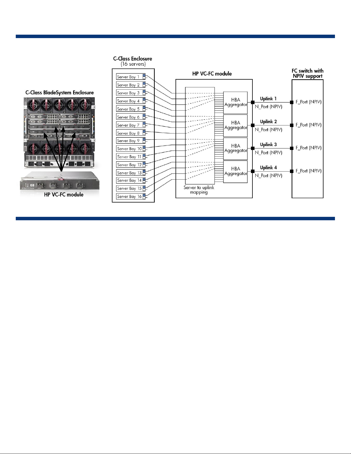
Two HP Virtual Connect Fibre Channel (VC-FC) modules are inserted in the lower interconnect bays of the c-Class BladeSystem
enclosure (see Figure 1-1).
connect to an external FC SAN fabric. The VC-FC modules allow administrators to organize and manage up to 16 servers in
the enclosure as a pool of servers in a SAN. The built-in VC Manager software allows administrators to assign a connection
profile to each server bay in the enclosure, not to physical servers, so that SAN connections remain constant even if a server is
added or replaced. Furthermore, a server profile can be moved from bay to bay in the enclosure.
Each of the HP VC-FC modules can aggregate up to 16 FC HBA ports through the enclosure mid-plane—together the modules
provide connectivity to redundant SANs. By default, each of the four uplinks is configured to aggregate up to 4 FC HBAs.
Additionally, each uplink can be configured to aggregate up to 8 or 16 FC HBAs. In essence, each VC-FC Module acts as a
pass-through device to the network. Any change to a server is transparent to its associated network. This separates the servers
from the SAN, relieving SAN administrators from server maintenance.
1
When installing the HP VC-FC Module in the c-Class enclosure, the HP 1/10Gb VC-Enet Module is also required because it contains the
processor that runs the VC Manager firmware.
1
The VC-FC modules connect to the enclosure mid-plane and feature four uplinks, or N_Ports, which
Page 2
ISS Technology Update Volume 7, Number 5
Figure 1-1. Port mapping for each VC-FC module installed in the ProLiant c7000 BladeSystem enclosure
The HP VC-FC module provides the following benefits:
• Server management is separated from LAN and SAN management. The SAN needs to be managed at the core switch only,
separate from BladeSystem enclosure management.
• Changing servers takes minutes instead of days, and servers can be added, replaced, and recovered without affecting SANs
or LANs.
• It is interoperable with multiple vendor fabrics (Brocade, McDATA, and Cisco).
• It does not consume a domain, thereby avoiding switch count scalability limit issues in a fabric and eliminating an additional
hop between switches.
• It reduces the number of cables and small form factor plug-ins (SFPs).
HP StorageWorks Brocade 4Gb SAN Switch using Access Gateway Mode
Access Gateway (AG) Mode is a software feature for p-Class and c-Class enclosures that can be enabled in Brocade
embedded switches. This feature is introduced in Brocade Fabric Operating System (FOS) v5.2.1b, and it does not require the
purchase of additional hardware or software beyond the Brocade-embedded switches themselves. After the AG Mode is
software-enabled, these switches act as simple port aggregators using NPIV technology. They use N_Port protocol to connect to
any vendor’s NPIV-compliant FC switch, and provide similar features as the VC-FC Module, except for the unique VC support
and manageability provided by the HP VC Manager software. Figure 1-2 shows the Brocade 4Gb SAN Switches for the cClass BladeSystem for a better comparison with the HP VC-FC Module, which works only in the c-Class enclosure.
The Brocade 4Gb SAN Switch for the c-Class enclosure in AG Mode offers a maximum of 24 ports, with a maximum of 16
ports that connect to the blade server HBAs and a maximum of eight external ports that can be used as uplink N_Ports. In AG
Mode, all eight external ports act as N_Ports supporting NPIV protocol and can connect to any standard FC switch that
supports NPIV-compliant F_Ports. AG Mode, like HP VC-FC, does not consume a domain and, therefore, helps to avoid
exceeding domain count limits in large fabrics with multiple blade enclosures.
2
Page 3

ISS Technology Update Volume 7, Number 5
Figure 1-2. Brocade 4GB SAN Switches installed in a ProLiant c7000 BladeSystem enclosure
The main benefits of the Brocade 4Gb SAN Switch using AG Mode are as follows:
• It is the only NPIV solution for HP p-Class enclosures.
• It provides a 2:1 server-to-uplink ratio for a fully populated enclosure with 16 servers.
• It has a flexible licensing option (12 or 24 ports, with a 12-port upgrade option for the 12-port model)
• It can be repurposed as either Switch Mode or AG Mode, but not in both modes simultaneously.
• It is interoperable with multiple vendor fabrics (Brocade, McDATA, and Cisco).
• It does not consume a domain, thereby avoiding switch count scalability limit issues in a fabric and eliminating an additional
hop between switches.
• It reduces the number of cables and small form factor plug-ins (SFPs).
• It eliminates the need for SAN management inside the enclosure after the initial connections have been configured.
Conclusion
HP VC-FC Module solutions are best suited in customer environments where the ability to manage servers without impacting
SANs is a high priority. The Brocade 4Gb SAN Switch using AG Mode may be a better choice for customers with different
requirements:
•need more than four FC uplinks.*
• use multiple WWNs on each HBA port (NPIV) on a server running ESX 3.5.*
• are not ready to adopt VC-Enet modules.
• have standardized on a non-HP Virtual Connect LAN environment.
• need Brocade proprietary subtle performance features such as multiple levels of priority.
* This will not be an issue for future HP VC-FC models
3
Page 4

ISS Technology Update Volume 7, Number 5
Additional resources
For additional information on the topics discussed in this article, visit:
Resource URL
Why Choose HP Virtual Connect
Enterprise Manager?
NPIV and Fibre Channel
interconnect options for HP
BladeSystem c Class white paper
What is NPIV? Web page
http://h20000.www2.hp.com/bc/docs/support/SupportMa
nual/c01373909/c01373909.pdf
http://h71028.www7.hp.com/ERC/downloads/4AA12234ENW.pdf
http://h71028.www7.hp.com/eNewsletter/cache/5845430-0-224-121.html
Delivering energy-efficient solutions for the IT power and cooling chain
According to DOE power consumption estimates, U.S. data centers consumed 61 billion kilowatt-hours in 2006. This represents
only 1.5 percent of the total U.S. power consumption. However, this power use is nearly doubling every year due the
increasing number of new and planned data centers.
Impending environmental regulation is creating a sense of urgency among businesses to improve overall efficiency of existing
and planned data centers before legislative action is taken to curb energy consumption.
One of the greatest challenges for HP is also one of its greatest opportunities—helping customers adopt next-generation, highdensity platforms in aging and/or crowded data centers while trying to improve the overall energy efficiency of these facilities.
Businesses are beginning to buy energy-efficient server and storage platforms; however, the best way for them to improve
overall data center efficiency is to change their day-to-day operating behavior. For example, a few years ago, the paradigm
shift from centralized computing to distributed computing infrastructures benefited businesses as well as the entire server
industry. However, this shift drove a great deal of processor “underutilization” resulting in considerable energy inefficiency.
Today, with average processor utilization hovering around 15 percent, virtualization is the most effective strategy to reduce
data center energy use. It can save up to 70 percent of the energy required to power servers. Storage consolidation—spindle
reduction—is also key to reducing energy use. If businesses change their operating behaviors to use these strategies, they can
achieve their business goals with fewer machines while improving their facilitie’s overall energy efficiency. These behavioral
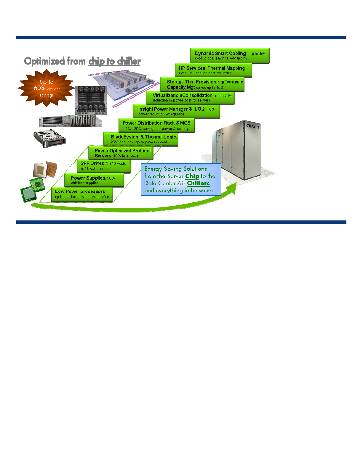
changes (Figure 2-1) are among a list of other steps that can be taken from the “chip to the chiller” to reduce energy use.
4
Page 5
ISS Technology Update Volume 7, Number 5
Figure 2-1. Behavioral changes
Businesses can take some immediate steps to reduce energy use:
• Low-power processors – The somewhat higher cost of low-power processors has discouraged some customers from requesting
them in their servers. However, customers who understand that the operating cost over the lifetime of a server is much higher
than its acquisition cost tend to use low-power processors to improve overall return on investment.
• Energy-efficient power supplies – Recently, there has been dramatic improvement in power supply efficiency. Only 3 years
ago, power supply efficiency was between 65 to 75 percent efficient, depending on the load. Today, HP power supplies can
be more than 90% efficient at 50 percent load.
• Power distribution racks – A power distribution rack is a rack-mounted breaker panel that does not use a transformer to step
down the voltage—it’s 208VAC in and 208VAC out. In contrast, transformer-based power distribution devices that step
down the voltage from 480VAC to 208VAC have energy losses. Changing to non-transformer-based power distribution can
reduce energy losses around 5 to 7 percent.
More importantly, businesses need to understand the HP holistic strategy. This strategy goes beyond the technologies inside
server or storage platforms. It involves factors that are centric to the room, for example, the air. First, air is a fluid, which means
that we can characterize its behavior in the room using computational fluid dynamics (CFD) modeling. Then, CFD enables us to
find ways to control the air to get the most cooling from it. By controlling the air, businesses can begin to adopt next-generation,
high-density platforms to get more equipment in the room. This may not reduce energy use; however, it can reduce the rate of
increase in energy use as customers adopt new platforms.
In summary, if businesses holistically change their operating behaviors to reduce energy use—or reduce the rate of increase in
energy use—they can extend the life of their facilities. These behaviors include virtualization, consolidation, and automation.
Factoring in the lead time and cost required to build a new data center, businesses can save millions of dollars for every year
they extend the life of their existing facility.
5
Page 6
ISS Technology Update Volume 7, Number 5
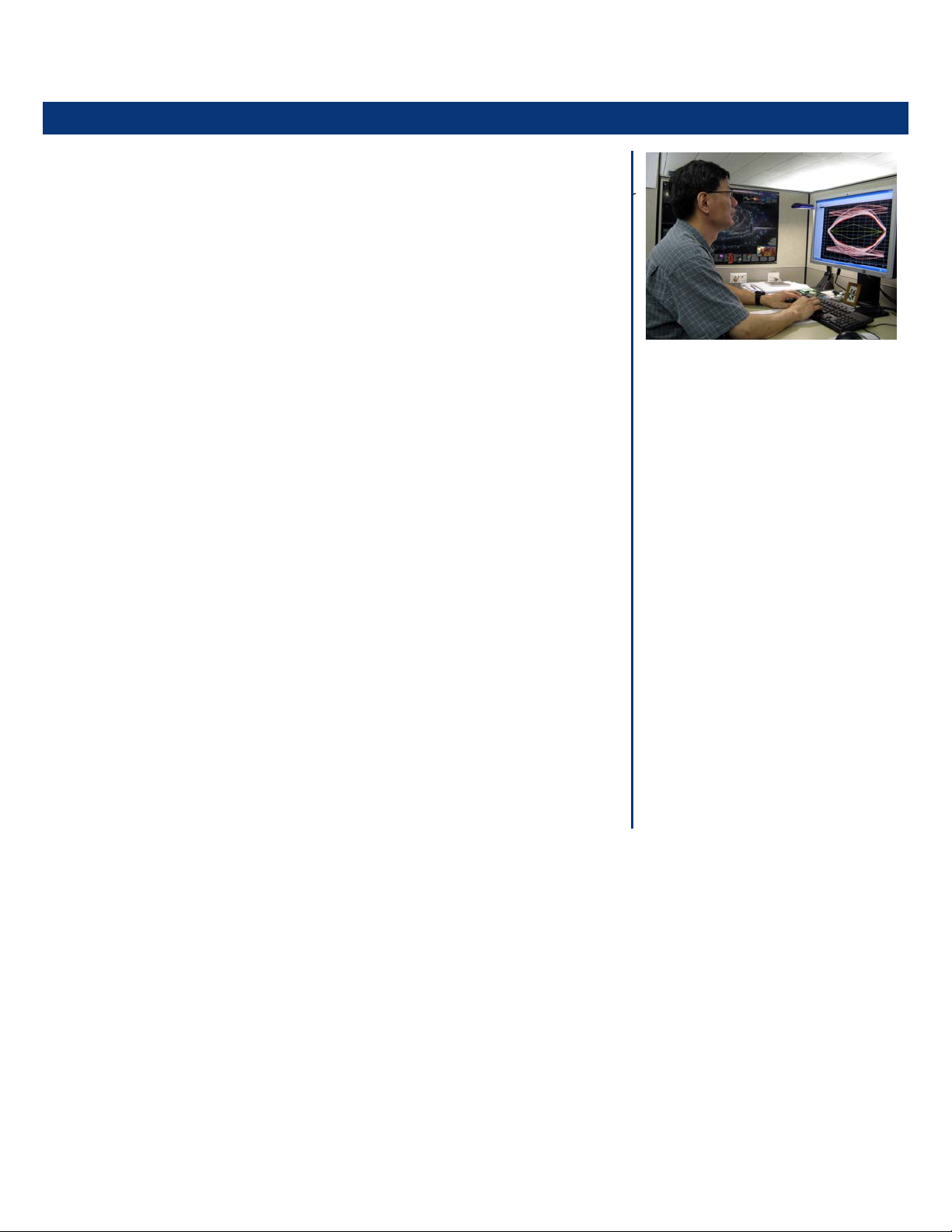
Meet the Expert—Michael Chan
Michael Chan’s 18-year career with Compaq/HP is proof that “timing is everything.” Michael has excelled in signal integrity
(SI) engineering due to his discipline and attention to detail. SI, which addresses signal timing and quality, is a critical
technology that impacts all levels of server platform design. SI analysis is performed using computer simulation because
signaling problems are extremely difficult to diagnose and solve after a system is built. If signaling problems are not understood
and solved prior to PCB fabrication, they can cause delays that increase the project cycle and development cost.
Michael began his career creating Spice models and working on Simultaneous
Switching Noise Analysis for ASIC package designs. Then he worked on
electromagnetic interference (EMI) design for various desktops, portables, servers,
array controller cards, and printers. After that he worked on device and system
level SI in the portable division. Since then, he has made significant contributions
to ISS platform designs, including the first Itanium servers, AMD servers, and now
BladeSystem servers. According to Michael’s manager, Mike Pelonero, “The SI
aspect of these designs has become more critical as processor, memory, and
overall system frequencies have increased as have design densities, especially
with regard to blade servers”
Michael’s expertise seems to spill over into some of his hobbies, and vice versa.
He enjoys audio amplifier construction, cassette deck repairs, plastic model
construction, and stamp collecting. He is the father of three—twins (a girl and boy)
age 11 and a boy age 8.
Below are excerpts from an interview with Michael Chan.
Why did you decide to become an engineer?
Ever since I was a kid, I’ve liked to build and repair stuff. In order to build things,
one needs to know how to meet the design specifications. At the same time,
repairing something requires one to understand how it works and why it broke. It
seems like engineering was my destiny.
What has been one of your most interesting research projects?
One of my most interesting research projects was analyzing the effect of highfrequency decoupling capacitors on laptop computers. We used to put a lot of
high-frequency decoupling capacitors with many different capacitance values into
Name: Michael Chan
Title: Hardware Design Engineer (ISSG)
Years at HP: 18
Patents:
• Chan, Michael Y., Leigh, Kevin B.
“Apparatus For Controlling The
Impedance of High-Speed Signals
on A Printed Circuit Board.” U. S
Patent 5764489. June 9, 1998.
• Chan, Michael Y., Leigh, Kevin B.
“Apparatus For Controlling The
Impedance of High-Speed Signals
on A Printed Circuit Board.” U. S
Patent 5986893. November 11,
1999.
• Chan, Michael Y., Riley, Dwight D.
“Point-To-Point Electrical Loading For
a Multi-Drop Bus.” U. S. Patent
7099966. August 29, 2006.
University/Degree
• University of Arizona at Tucson:
Bachelor of Science Geosciences
• University of Arizona at Tucson:
Master of Science Electrical
Engineering”
our laptop products. The decision to use that many capacitors was based on rules
of thumb. This practice increased both the cost of the product as well as component inventory costs.
We made some emission measurements on one laptop and found out that there was very little difference in terms of emission
level detected between a laptop that is fully populated with high-frequency decoupling capacitors and one with no capacitors.
At that moment, we still did not know if the capacitors were ineffective or whether something caused those capacitors to
become ineffective.
We then performed some computer simulations and found out that the capacitor mounting structure had so much inductance
that it rendered all the capacitors ineffective. We modified the design of the mounting structure and repeated the simulation.
We also reduced number of capacitors, and the emission level improved significantly. We finally decided to reduce the number
of high-frequency capacitors as well as the capacitance values of those being used. This significantly reduced the component
cost in our future laptop products.
6
Page 7

ISS Technology Update Volume 7, Number 5
What changes do you think are necessary for HP to remain the leader in industry-standard servers?
First, we need to continue to differentiate our products from those of our competitors. We cannot rely on the strategy to have
what our competitors also have. We need to continue to develop products with features our customers want but our competitors
cannot provide.
Second, the industry-standard server business model has worked in the past for high-volume and low-cost products, but this
business model may not suit customer requirements for the future. High-performance and high-reliability may be the model for
the future. I think HP should continue to invest in Research and Development for future server products in areas such as highspeed interconnects, efficient power management, parallel processing, and system reliability.
Deploying HPSUM firmware and software updates
HP Smart Update Manager (HPSUM) is a utility for updating firmware and software smart components on HP ProLiant servers,
options, and enclosures. HPSUM supports firmware and software update deployment to target servers running Microsoft®
Windows® Server 2003 (x86 and x64 Editions), Microsoft® Windows® Server 2008 (x86 and x64 Editions), Red Hat
Enterprise Linux (RHEL) 3, 4, and 5, and SUSE Linux Enterprise Server (SLES) 9 and 10. Upgrades can be deployed from
Windows® XP and Windows Vista® workstations to remote targets.
HPSUM includes many features:
• Support for local and remote (one-to-many) deployments
• Support for local deployment to bare metal through boot from USB Key or Firmware Maintenance CD
• Support for remote deployment to bare metal targets when used in conjunction with the SmartStart Scripting Toolkit (SSSTK),
iLO Virtual Media Support, or BladeSystem Firmware Deployment Tool
• Available on the ProLiant Essentials Firmware Maintenance CD
• The deployment engine for Version Control in Windows
• Integrated with the Remote Deployment Program (RDP) as of Version 3.10 release
HPSUM provides the following firmware flash support:
• System ROM
• RILOE II/iLO/iLO2
• Smart Array controllers
• SAS hard drives
• SATA hard drives (offline only)
• SCSI hard drives (offline only)
• MSA 20, 500, 500 G2, 60 and 70 enclosures
• BladeSystem c-Class Onboard Administrators (OA)
NIC Firmware
• QLogic Fibre Channel Host Bus Adapters (offline only)
• Emulex Fibre Channel Host Bus Adapters (offline only)
• Tape firmware
Consider the following best practices when using HPSUM:
• No more than 16 servers or OAs should be grouped together for an installation
• Start with the latest Firmware Maintenance CD to ensure that you have the latest version of HPSUM for firmware updates
• Always download the latest firmware from the
www.hp.com website to use with HPSUM
7
Page 8

ISS Technology Update Volume 7, Number 5
For more information, refer to the HPSUM User Guide located in the \compaq\docs directory on the Firmware Maintenance
CD or on the web:
http://h20000.www2.hp.com/bc/docs/support/SupportManual/c00679482/c00679482.pdf?jumpid=reg_R1002_USEN.
Software management life cycle
The lifecycle of server software management
includes three phases: active notification and
acquisition, version control, and distribution and
installation.
• Active notification and acquisition is the phase
where administrators learn that new software is
available and acquire it.
• Version control is the phase where administrators
determine whether the updated software is
applicable to their environments and what issues
they need to understand before deciding to
install a software update.
• Distribution and installation is the phase that
involves installing the software on the desired
systems within the customer’s environment.
HPSUM deployment scenarios
Figure 4-1. Software management life cycle
Scenario 1 – Remote deployment of firmware to c-Class server blades with installed operating systems and Onboard Administrators
This deployment scenario has certain requirements:
• The target servers have a hosted OS that is a supported version of Windows or Linux, which is already installed and running
• OA must be on a network accessible from the HPSUM Management Console (where HPSUM is running)
Use these steps to deploy firmware to c-Class server blades with installed operating systems and Onboard Administrators:
1. Download the latest ProLiant Essentials Firmware Maintenance CD and create a CD from the ISO image.
2. Create a USB key (2GB recommended) using the HP USB Key Utility for Windows.
3. Copy updated ROMs from the web and add them to the \compaq\swpackages directory on the USB key.
4. Run autorun from the USB key:
• Windows \autorun\autorun_win.exe
• Linux ./autorun
5. Click on Firmware tab.
6. Click on Install Firmware link to start HPSUM or start HPSUM manually by running \compaq\swpackages\hpsum.
8
Page 9

ISS Technology Update Volume 7, Number 5
Scenario 2 – Using HPSUM through command-line in an existing customer deployment solution
NOTE
The OA must be updated using Scenario 1 or the OA web interface. OA component can be
scripted by itself by using the smart component with command-line parameters.
Use these steps to deploy firmware to c-Class server blades with installed operating systems and Onboard Administrators:
1. Download the latest ProLiant Essentials Firmware Maintenance CD and create a CD from the ISO image.
2. Create a USB key (2GB recommended) using the HP USB Key Utility for Windows.
3. Copy updated ROMs from the web and add them to the \compaq\swpackages directory on the USB key.
4. Execute HPSUM manually by running \compaq\swpackages\hpsum /silent.
NOTE
The /silent option must be used to suppress the GUI.
Other useful command-line options are listed in Table 4-1.
Table 4-1. HPSUM command-line options
Command Description
/force Force the installation of all components even if the same version or an older version is installed.
/reboot Reboot the server if a successful installation occurred.
/dryrun Simulate an installation but do not actually install.
/g Downgrade multi-target firmware for all targets.
/e Rewrite multi-target firmware if the installed version is the same as the deployed version.
Scenario 3 – Using PXE to remotely deploy firmware to c-Class server blades without operating systems
NOTE
The OA must be updated using Scenario 1 or the OA web interface. OA component can be
scripted by itself by using the smart component with command-line parameters.
1. Download the SmartStart Scripting Toolkit at www.hp.com/servers/sstoolkit.
2. Download the latest ProLiant Essentials Firmware Maintenance CD and create a CD from the ISO image.
3. Obtain a version of Windows PE 2005, which is required to create the image for remote deployment.
4. Create a USB key (2GB recommended) using the HP USB Key Utility for Windows.
5. Copy updated ROMs from the web and add them to the \compaq\swpackages directory on the USB key.
6. Create a network share off the common server as illustrated in Figure 4-2.
9
Page 10
ISS Technology Update Volume 7, Number 5
Figure 4-2. Create network share
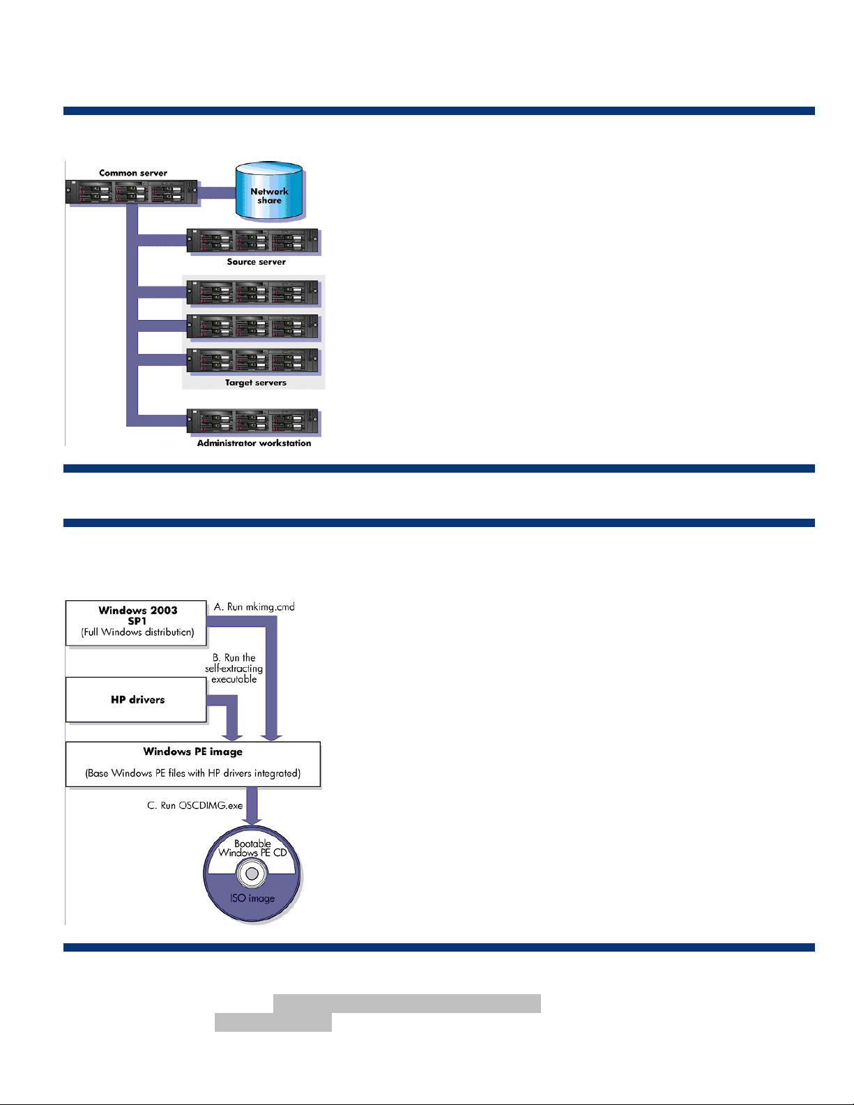
7. Prepare the boot media as indicated in Figure 4-3.
Figure 4-3. Create boot media
8. To flash firmware, create a script file to perform the following tasks:
a. Run the HPSUM in silent mode \compaq\swpackages\hpsum /silent.
b. Check the error level \if errorlevel ….
10
Page 11

ISS Technology Update Volume 7, Number 5
NOTE
The following script is provided as an example only and must be modified for your
lar environment. Additional checks can be added as needed. The capitalized text
particu
(SUCCESS, REBOOTREQUIRED, and NOTREQUIRED) must be modified to customiz
script.
REM This section performs the firmware update. Online Flash
components
REM and HPSUM are kept in a directory called Roms
REM ---- RUN HPSUM in SILENT MODE using /s or /silent switch
\Roms\HPSUM /s
REM ---REM Check the error code returned to determine Success or Failure
REM ---if errorlevel 0 goto SUCCESS
if errorlevel 2 goto REBOOTREQUIRED
if errorlevel 3 goto NOTREQUIRED
REM --REM Reboot the server
REM --\system\reboot c:
e the
The PXE image location i
ecified by the PXE Bootloader either pxelinux or Microsoft ADS. sp
s specified as part of the DHCP server configuration and further
9. Boot the remote target servers and start PXE (normally by pressing the F12 key) during startup. Allow the scripts to run and
the server to reboot.
11
Page 12

ISS Technology Update Volume 7, Number 5
Scenario 4 – Using the Firmware Deployment Tool to remotely deploy firmware to c-Class server blades without operating systems
NOTE
The OA must be updated using Scenario 1 or the OA web interface. OA component can be
scripted by itself by using the smart component with command-line parameters.
1. Download the BladeSystem Firmware Deployment Tool at http://h18004.www1.hp.com/products/blades/components/c-
class-compmatrix.html and choose the Server Blade Firmware & Drivers link, which is located under the “Firmware and
management tool upgrades” section of the Web page.
2. Download the latest HP BladeSystem Firmware Deployment Tool CD and create a CD from the ISO image.
3. Using the ISO image or the physical CD, use one of the following methods to deploy the firmware to target servers:
• Deploy through Onboard Administrator and then connect through the server's iLO remote console
• Boot from mounted ISO image on server blade
• Boot from mounted physical CD image on server blade
• Boot from mounted USB image on blade
• Deploy using the Onboard Administrator enclosure DVD driveUse the Onboard Administrator Insight Display to start
CD on each enclosure
• Use the Onboard Administrator console to start CD on each server in the enclosure
• Deploy using PXE boot service
• Deploy using the server's iLO Virtual Media applet by completing the following:
– Boot from mounted ISO image
– Boot from mounted physical CD image
– Boot from mounted USB image
NOTE
The HP BladeSystem Firmware Deployment Tool CD is an automated ISO image that is meant to
be used to deploy firmware to target servers in a hands-off manner. It is effective in updating
firmware on blade servers prior to deploying an operating system (bare-metal). The ISO image
will boot, update all the firmware on the server on which it has been booted, and then reboot
the server. There is no user interface provided with the HP BladeSystem Firmware Deployment
Tool. However, iLO’s Remote Console functionality can be used to watch the progress of the
update on the target server.
In the event of a failure, the FWDT will turn on the UID light and load the installation log in an editor. A user must use the iLO
Remote Console to view the data on the failing server.
12
Page 13

ISS Technology Update Volume 7, Number 5
Implementing a scalable, highly available Oracle® Database for SMBs
Most small to mid-size businesses (SMBs) do not have the resources to deploy highly available servers that are needed for 24x7
access to critical applications. Instead, SMBs usually rely on single server systems, causing them to experience periods of down
time that negatively impact revenue and customer service, and ultimately, customer satisfaction. Even upgrading their server can
cause major disruptions.
Larger corporations with dedicated IT staff and bigger budgets have been able to deploy highly scalable and available
solutions using clustering technologies like Oracle® Real Application Clusters (RAC). Until recently, the cost and the complexity
of setting up this type of infrastructure have limited the ability of SMBs to provide similar levels of service for their customers.
Oracle has made great advances in reducing the complexity and cost of clustering by introducing Oracle® Database Standard
Edition (SE), which includes RAC at no additional charge (for up to four sockets in a cluster). RAC functionality allows customers
to implement a high availability environment at a much lower cost than was previously possible. In addition, the management
of clustered environments has been dramatically improved by complementary Oracle technologies such as clustered file systems
and Oracle® Enterprise Manager. However, the complexity of the hardware configuration and operating system set-up can
still stifle the decision to implement such a cluster environment.
This article describes a scalable and highly available solution using HP BladeSystem hardware with Oracle Database SE
including RAC, which reduces the cost and complexity for SMBs to deploy 24x7 solutions.
Traditional clustering implementations for 24x7 Operations
Prior to the HP/Oracle RAC solution, SMBs had to choose between two traditional clustering options: an active/passive cluster
or an active/active cluster.
Active/passive clusters
Many cluster implementations use an active/passive approach in which the servers and storage are physically connected
together (Figure 5-1), but only one server at a time can run the database and access storage. In the event of a failure, the
database is started on the second server, which requires users to reconnect. This results in downtime and performance issues
that can last several minutes. This may be acceptable in some cases, but there are situations where loss of data access can
have a significant negative impact on business. Examples of active/passive clusters include Microsoft® Cluster Server and HP
Serviceguard. Table 5-1 summarizes the strengths and weaknesses of active/passive clusters.
Figure 5-1. Active/passive cluster example
13
Page 14

ISS Technology Update Volume 7, Number 5
Table 5-1. Strengths and weaknesses of active/passive clusters
Strengths Weaknesses
• High availability with less down time than single systems.
• Secondary node can be used for separate applications during
passive mode.
• Relatively small failover time (< 30 minutes).
• Failover can be automated with cluster management tools
such as HP Serviceguard and Oracle Data Guard.
• Application licensing is often only required for a single server.
• Databases and applications have to be restarted impacting
availability and performance.
• Multiple systems have to be managed.
• Complex configuration issues occur.
• Users must reconnect or be reconnected to the second node in the
event of a failover.
• Can result in underutilized server resources.
• No instantaneous or transparent application failover.
Active/Active Clusters
In an active/active (Figure 5-2), both servers are physically connected to the storage and both can access the storage
simultaneously. This is a valuable solution for database environments. In this environment, the database vendor has to provide a
distributed lock management capability to prevent data corruption that could arise from simultaneous access from two separate
systems. Examples of this type of clustering are Oracle Real Application Clusters (RAC), RedHat GFS cluster file system, and HP
PolyServe cluster file gateway.
Figure 5-2. Active/Active Cluster Example
Table 5-2. Strengths and weaknesses of active/active clusters
Strengths Weaknesses
• High availability with less down time than single systems.
• Both nodes are active participants in the cluster.
• Very short failover time (< 90 seconds).
• Failover can be automated with cluster management tools
such as HP Serviceguard and Oracle Enterprise Manager.
• The investment of each server in the cluster is used.
• With Oracle RAC, the cluster can be dynamically expanded.
• Complex infrastructure combining many separate components
• Multiple systems to manage
• Complex configuration issues for setup and maintenance
• Licensing for both servers can result in higher application costs
14
Page 15

ISS Technology Update Volume 7, Number 5
The HP/Oracle “RAC in a box” solution
The issue that is common to active/passive and active/active clusters is the complexity of the hardware infrastructure. System
installation, deployment, and management can be complicated and expensive, especially for an SMB customer. The solution is
to use a combination of HP c-Class BladeSystem technology, Linux OS, and Oracle RAC (Figure 5-3). The major advantages of
the HP/Oracle RAC in a box solution are summarized in Table 3.
Figure 5-3. HP/Oracle RAC in a box
c3000 Tower
Enclosure
BL460c Server
Node #1
BL260c Server
Quorum/App
BL460c Server
Node #2
AiO SB600c
Storage Blade
AiO SB600c
Storage Blade
Table 5-3. HP/Oracle RAC in a box
Advantages
Easy to deploy
Easy to manage • Storage can be set up easily using the AiO SB600c intuitive interface. It
Highly available • There is no single point of failure in the hardware because the blade
Lower cost
• Everything is in one chassis (HP BladeSystem c3000 or c7000 enclosure)
• Configuration and best practices are provided.
allows simple setup of LUNs, which can be served to the clients using iSCSI,
NFS or a combination of both.
• All of the components are stored within the enclosure, reducing wiring
complexity and costs.
• The only external cables are Ethernet for connectivity and power.
enclosure has a totally passive backplane.
• Dual power supplies and fans ensure availability.
• Two Real Application Cluster nodes provide compute availability.
• The BL260c provides application server and cluster quorum capability.
• ASM is used to mirror database files across AiO SB600c storage devices.
• Internal NAS storage is less expensive than an external SAN.
Easily expandable
• Additional external NAS can be added.
• Additional SAN capacity can be added.
• Additional server nodes can be added.
15
Page 16

ISS Technology Update Volume 7, Number 5
Additional resources
For additional information on the topics discussed in this article, visit:
Resource URL
HP
StorageWorks
All-in-One
SB600c Storage
Blade
HP BladeSystem c3000 Enclosure http://h18004.www1.hp.com/products/blades/components/enclosures/c-
HP/Oracle
storage solutions
HP ProLiant BL460c server http://h18004.www1.hp.com/products/servers/proliant-bl/c-
Open Source and Linux from HP http://h71028.www7.hp.com/enterprise/cache/309906-0-0-0-
AiO Storage
Systems
AiO SB600c data
sheet
AiO SB600c
product page
AiO whitepapers
HP & Oracle
Alliance
HP Storage for
Oracle – Solution
Demos
Oracle validated
configurations
Storage Solutions
for Oracle
www.hp.com/go/aiostorage
www.hp.com/sbso/serverstorage/proliant_business_advantage/storageworkssb600c.pdf
http://h18006.www1.hp.com/products/storageworks/sb600c/index.html
http://h18006.www1.hp.com/storage/aiowhitepapers.html
class/c3000/
http://h71028.www7.hp.com/enterprise/cache/4281-0-0-0-121.html
http://h20324.www2.hp.com/hpsdp/index.jsp?auto=1&ib=5009160&categ
ory_id=5021586&demo_id
www.oracle.com/technology/tech/linux/validated-configurations/index.html
http://h71028.www7.hp.com/enterprise/cache/548605-0-0-0-121.aspx
class/460c/index.html
121.html?jumpid=go/linux
16
Page 17

ISS Technology Update Volume 7, Number 5
Recently published industry standard server technology communications
Title URL
Implementing Microsoft Windows Essential Business
Server 2008 Release Candidate 0 on HP ProLiant servers
− Integration Note
Performance factors for HP ProLiant Serial Attached
Storage (SAS) − Technology Brief
Server virtualization technologies for x86-based HP
BladeSystem and HP ProLiant servers, 2
Technology Brief
nd
edition −
http://h20000.www2.hp.com/bc/docs/support/SupportManual/c01467
895/c01467895.pdf
http://h20000.www2.hp.com/bc/docs/support/SupportManual/c01460
725/c01460725.pdf
http://h20000.www2.hp.com/bc/docs/support/SupportManual/c01067
846/c01067846.pdf
Industry standard server technical communications can be found at www.hp.com/servers/technology.
Contact us
Send comments about this newsletter to TechCom@HP.com.
Legal Notices
© Copyright 2008 Hewlett-Packard Development Company, L.P. The information contained herein is subject to
change without notice. The only warranties for HP products and services are set forth in the express warranty
statements accompanying such products and services. Nothing herein should be construed as constituting an
additional warranty. HP shall not be liable for technical or editorial errors or omissions contained herein.
AMD and AMD Opteron are trademarks of Advanced Micro Devices, Inc.
Microsoft, Windows, Windows XP, and Windows Vista are US registered trademarks of Microsoft Corporation.
Oracle is a registered trademark of Oracle Corporation and/or its affiliates.
TC080506NL
May 2008
 Loading...