

Page 1

Irvine Motherboard
User’s Manual
Page 2

Statement:
This manual is the intellectual property of HP, Inc. Although the
information in this manual may be changed or modied at any time,
Foxconn does not obligate itself to inform the user of these changes.
Trademark:
All trademarks are the property of their respective owners.
Version:
User's Manual V1.0 for Irvine motherboard.
Symbol description:
Caution : refers to important information that can help you to use
motherboard better, and tells you how to avoid problems.
Warning: indicating a potential risk of hardware damage or physical
injury may exist.
WEEE: The use of this symbol indicates that this product may not
be treated as household waste. By ensuring this product is
disposed of correctly, you will help prevent potential negative
consequences for the environment and human health, which
could otherwise be caused by inappropriate waste handling
of this product. For more detailed information about recycling
of this product, please contact your local city ofce, your
household waste disposal service or the shop where you
purchased this product.
W
A
R
N
I
N
G
!
C
A
U
T
I
O
N
!
© All rights reserved.
All trade names are registered trademarks of respective manufacturers listed.
All images are for reference only, please refer to the physical motherboard for specic features.
Page 3

Table of ConTenTs
Chapter 1 Product Introduction
Product Specications ................................................................ 2
Layout ......................................................................................... 4
Back Panel Connectors .............................................................. 5
Chapter 2 Hardware Install
Install the CPU ........................................................................... 7
Install the Memory ...................................................................... 9
Install an Expansion Card..........................................................11
Install other Internal Connectors .............................................. 12
Jumpers .................................................................................... 14
Chapter 3 BIOS Setup
Enter BIOS Setup ..................................................................... 17
Main Menu ................................................................................ 18
Advanced Menu ....................................................................... 19
Power Menu ............................................................................. 21
Boot Menu ................................................................................ 22
Exit Menu.................................................................................. 24
Page 4
Installation Precautions
■ Electrostatic discharge (ESD) is the sudden and momentary electric
current that ows between two objects at different electrical potentials.
Normally it comes out as a spark which will quickly damage your electron-
ic equipment. Please wear an electrostatic discharge (ESD) wrist strap
when handling components such as a motherboard, CPU or memory.
■ Ensure that the DC power supply is turned off before installing or
removing CPU, memory, expansion cards or other peripherals. It is
recommended to unplug the AC power cord from the power supply outlet.
Failure to unplug the power supply cord may result in serious damage to
your system.
Please carefully read the following procedures to install your computer :
■ It is suggested to select high-quality, certied fans in order to avoid
damage to the motherboard and CPU due to high temperature. Never
turn on the computer if the CPU fan is not properly installed.
■ We cannot guarantee that your system can operate normally when
your CPU is over-clocked. Normal operation depends on the over-clock
capacity of your device.
■ When connecting hardware components to the internal connectors on the
motherboard, make sure they are connected tightly and securely.
■ When handling the motherboard, avoid touching any metal leads or
connectors.
■ Before turning on the power, please make sure the power supply A/C
input voltage setting has been congured to the local standard.
■ To prevent damage to the motherboard, do not allow screws to come
in contact with the motherboard circuit or its components. Also, make
sure there are no leftover screws or metal components placed on the
motherboard or within the computer casing.
■ If you are uncertain about any installation steps or have a problem related
to the use of the product, please consult a certied computer technician.
W
A
R
N
I
N
G
!
C
A
U
T
I
O
N
!
Page 5

Thank you for buying HP’s Irvine motherboard. This motherboard
is one of our new products, and offers superior performance,
reliability and quality, at a reasonable price. This motherboard
adopts the advanced NVIDIA GeForce 7100 / nForce 630i
chipset, providing users a computer platform with a high
integration-compatibility-performance price ratio.
This chapter includes the following information:
■ Product Specications
■ Layout
■ Back Panel Connectors
Page 6

2
1-1 Product Specications
CPU Support for Intel® CoreTM 2 Duo E6x50, E6x20, E6x00, E4x00 (Conroe)
processors / Intel® Pentium® Dual Core E2xx0 (Conroe1M) processor /
Intel® Celeron® 4xx (Conroe-L) processor in the LGA 775 package
Support for Intel® Hyper-Threading Technology
Front Side Bus 1333/1066/800 MHz (FSB)
Chipset NVIDIA GeForce 7100 / nForce 630i
Memory 2 x 240-pin DDR2 DIMM sockets
Support up to 4GB of system memory
Single channel DDR2 800/667/533MHz architecture
Onboard Graphics Integrated in the GeForce 7100 / nForce 630i Chipset
Audio Realtek ALC888S-GR codec
High Denition Audio
2/4/5.1-channel
Support for S/PDIF Out
Support Jack-Sensing function
LAN RTL 8201 10/100Mb/s Ethernet PHY
Expansion Slots 1 x PCI Express x16 slot
1 x PCI Express x1 slot
Onboard Serial ATA II 2 x SATA II connectors
300MB/s data transfer rate
Support hot plug and NCQ (Native Command Queuing )
USB Support hot plug
Support up to 10 USB 2.0 ports (4 rear panel ports, 3 onboard USB
headers providing 6 extra ports)
Supports USB 2.0 protocol up to 480Mb/s
Internal Connectors 1 x 24-pin ATX main power connector
2 x SATA connectors
3 x USB 2.0 headers (supporting 6 x USB devices)
1 x CPU fan header (4-pin)
1 x Front panel header
1 x Front audio header
1 x S/PDIF_OUT header
Back Panel 1 x PS/2 keyboard port
Connectors 1 x PS/2 mouse port
1 x Coaxial S/PDIF Out connector
1 x VGA port
4 x USB 2.0/1.1 ports
1 x RJ-45 port
1 x 1394a port
1 x DVI port
6 x audio jacks (Center/Subwoofer Speaker Out/Rear Speaker Out/Side
Speaker Out/Line In/Line Out/Microphone)
Page 7

3
Hardware Monitor CPU temperature detection
CPU fan speed detection
CPU fan speed control
Onboard 1394a Support hot plug
400 Mb/s transmission rate
Support 1 independent 1394 unit synchronously
PCI Express x1 Support 250MB/s (500MB/s concurrent) bandwidth
Low power consumption and power management features
PCI Express x16 Support 4GB/s (8GB/s concurrent) bandwidth
Low power consumption and power management features
Green Function Support ACPI (Advanced Conguration and Power Interface)
Support S0 (normal), S1 (power on suspend), S3 (suspend to RAM), S4
(Suspend to disk), and S5 (soft - off)
Operating System Support for Microsoft® Windows® Vista 32 bit and 64 bit/Linux/Free Dos
Form Factor Mini ITX Form Factor, 193mm x 173mm
Page 8
4
12
14
7
8
9
10
11
13
6
1
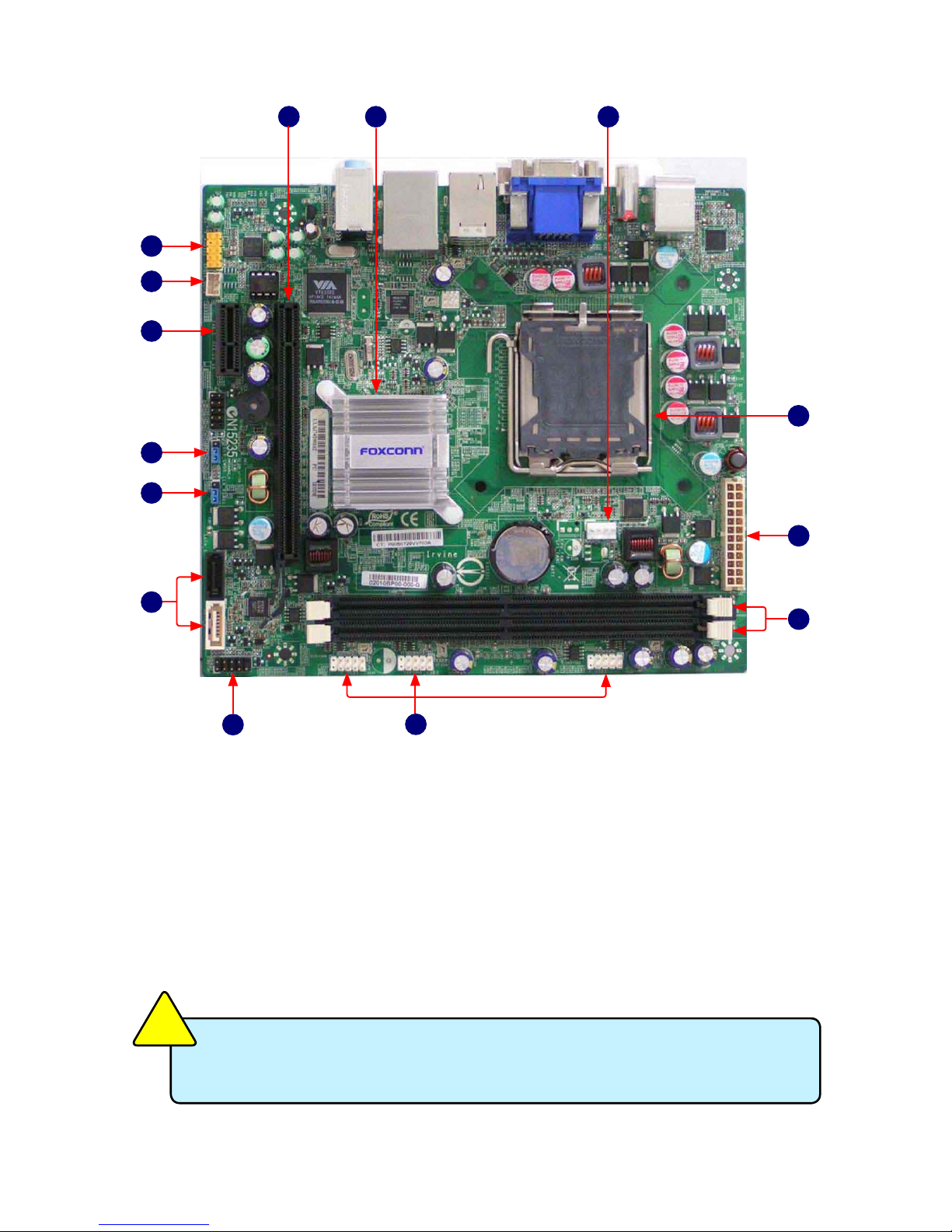
1. Front Audio Connector
2. SPDIF_OUT2 header
3. PCI Express x1 Slot
4. Clear CMOS Jumper
5. CLR_PSWD1 Jumper
6. SATA II Connectors
7. Front Panel Connector
8. Front USB Connectors
1-2 Layout
2
3
4
5
8. Front USB Connectors
9. DDR2 DIMM Slots
10. 24-pin ATX Power Connector : PWR1
11. LGA 775 CPU Socket
12. CPU_Fan Connector
13. Chipset: NVIDIA GeForce 7100 /
nForce 630i
14. PCI Express x16 Slot
The above motherboard layout is provided for reference only;
please refer to the physical motherboard.
C
A
U
T
I
O
N
!
Page 9
5
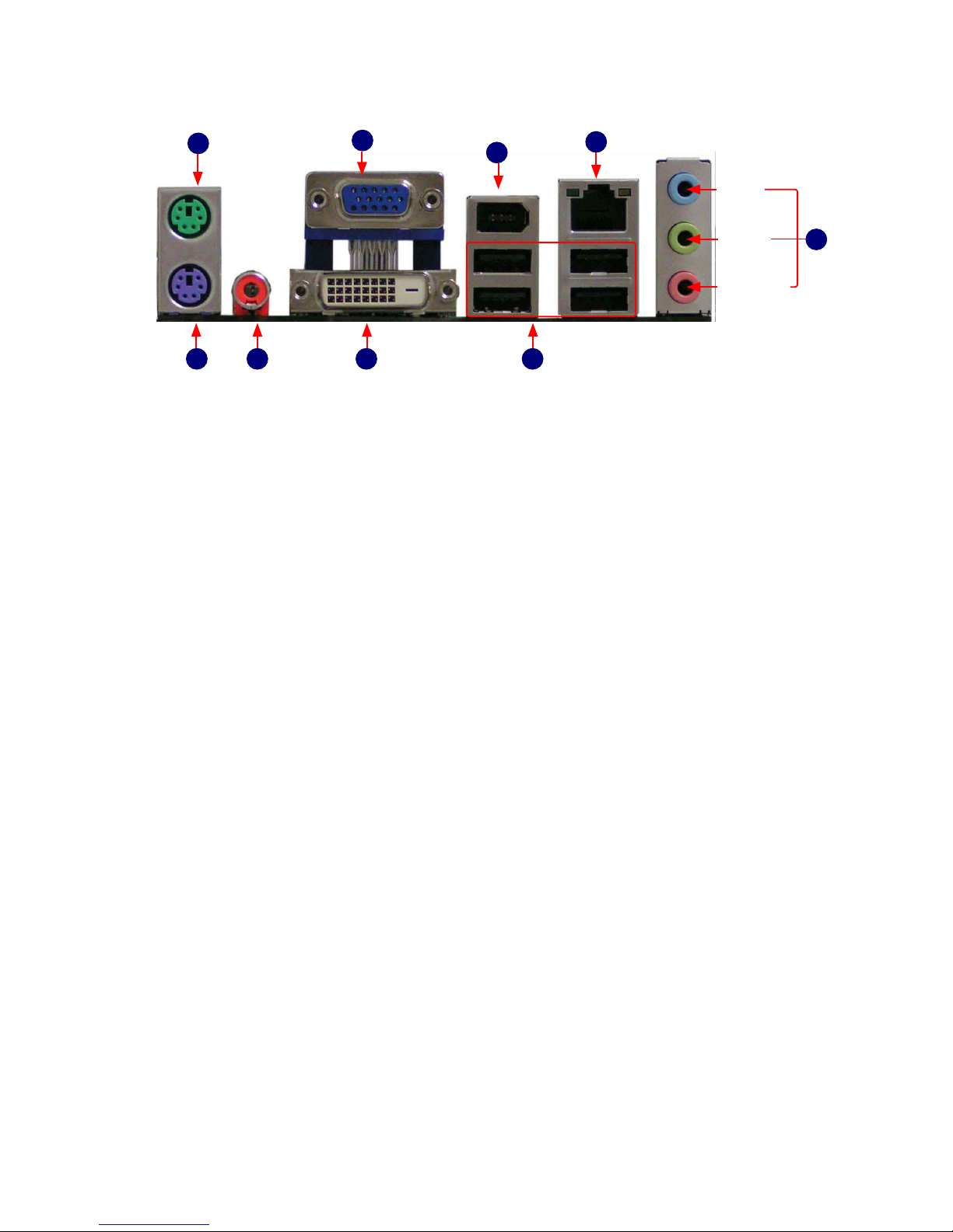
1-3 Back Panel Connectors
1. PS/2 Mouse Port
Use the upper port (green) to connect a PS/2 mouse
2. PS/2 Keyboard Port
Use the lower port (purple) to connect a PS/2 keyboard.
3. Coaxial S/PDIF Out Connector
This connector provides digital audio out to an external audio system that supports
digital coaxial audio. Before using this feature, ensure that your audio system
provides a coaxial digital audio in connector.
4. DVI Port
DVI stands for Digital Visual Interface, and is a standard for connecting computers
to digital monitors. The DVI port provides a pure digital video signal to a digital at-
panel display or projector.
5. USB Port
The USB port supports the USB 2.0/1.1 specication. Use this port for USB devices
such as an USB keyboard/mouse, USB printer, USB ash drive and etc.
6. Line in, Line out, Mic In Jacks
Line In Jack (Blue)
The default line in jack. Use this jack to connect with line out port from devices
such as an Audio CD player, PC line out...etc.
Line Out Jack (Green)
The default line out jack. Use this audio jack for a headphone or 2-channel
speaker.
Mic In Jack (Pink)
The default Mic in jack. Microphone must be connected to this jack.
7. RJ-45 LAN Port
The LAN port provides Internet connection at up to 10/100Mb/s data rate.
8. 1394a Port
Use this port to connect with your 1394a supported video recorder device or any
1394 peripheral.
9.VGA Port
Use this port to to connect with your display monitor.
DVI Port
VGA Port
USB 2.0 Ports
LAN Port
S/PDIF
Coax Port
PS/2
Keyboard Port
PS/2 Mouse Port
Line-out
Microphone
Line-in
5
7
9
1
2
3 4
1394a Port
8
6
Page 10

This chapter introduces the hardware installation process,
including the installation of the CPU, memory, power supply,
slots, and pin headers, and the mounting of jumpers. Caution
should be exercised during the installation of these modules.
Please refer to the motherboard layout prior to any installation
and read the contents in this chapter carefully.
This chapter includes the following information:
■ Install the CPU
■ Install the Memory
■ Install an Expansion Card
■ Install other Internal Connectors
■ Jumpers
Page 11

7
Read the following guidelines before you begin to install the CPU:
■ Make sure that the motherboard supports the CPU.
■ Always turn off the computer and unplug the power cord from the
power supply before installing the CPU to prevent hardware damage.
■ Locate the pin one of the CPU. The CPU cannot be inserted if oriented
incorrectly. (Or you may locate the notches on both sides of the CPU
and alignment keys on the CPU socket.)
■ Apply an even and thin layer of thermal grease on the surface of the
CPU.
■ Do not turn on the computer if the CPU cooler is not installed,
otherwise overheating and damage of the CPU may occur.
■ Set the CPU host frequency in accordance with the CPU
specications. It is not recommended that the system bus frequency be
set beyond hardware specications since it does not meet the standard
requirements for the peripherals. If you wish to set the frequency
beyond the standard specications, please do so according to your
hardware specications including the CPU, graphics card, memory,
hard drive, etc.
Hyper-Threading Technology System Requirements:
(Go to Intel's website for more information about the Hyper-
Threading Technology)
■ An Intel® CPU that supports HT Technology
■ A chipset that supports HT Technology
■ An operating system that is optimized for HT Technology
■ A BIOS that supports HT Technology and has it enabled
C
A
U
T
I
O
N
!
2-1 Install the CPU
Install the CPU
A. Locate the alignment keys on the motherboard CPU socket and the
notches on the CPU.
Pin one triangle marking of CPU
LGA775 CPU
Notch
LGA775 CPU Socket
Alignment Key
Pin One Corner of the CPU Socket
Page 12

8
Before installing the CPU, make sure to turn off the computer and
unplug the power cord from the power outlet to prevent damage to
the CPU.
C
A
U
T
I
O
N
!
1. Release the CPU socket
level
2. Remove protective socket
cover
3. Lift the metal cover on the
CPU socket
5. When CPU is properly
seated, replace the metal
cover and push the CPU
socket level back to its locked
position.
4. Check pin one marking
(triangle) with the pin one
corner of the CPU socket,
align the CPU notches with
the socket alignment keys and
gently put the CPU onto the
socket.
B. Follow the steps to install the CPU onto the CPU socket.
Page 13

9
2-2 Install the Memory
If you take a look at front side of memory module, it has asymmetric pin
counts on both sides separated by a notch in the middle, so it can only t in
one direction. Follow the steps below to correctly install your memory modules
into the sockets.
Notch
Read the following guidelines before you begin to install the Memory:
■ Make sure that the motherboard supports the memory. It is
recommended that memory of the same capacity, brand, speed, and
chips be used.
■ Always turn off the computer and unplug the power cord from the
power outlet before installing the memory to prevent hardware damage.
■ Memory modules have a foolproof design. A memory module can be
installed in only one direction. If you are unable to insert the memory,
switch the direction.
■ DDR2 DIMMs are not compatible to DDR DIMMs. Be sure to install
DDR2 DIMMs on this motherboard.
C
A
U
T
I
O
N
!
Memory Conguration
This motherboard provides two DDR2 memory sockets. After the memory is
installed, the BIOS will automatically detect the specications and capacity of
the memory.
112-Pin128-Pin
Page 14

10
Step 1:
Spread the clips at both ends of the memory socket. Place the memory
module onto the socket, then put your ngers on top edge of the module, and
push it down rmly and seat it vertically into the memory socket.
Step 2:
The clips at both ends of the socket will snap into place when the memory
module is securely inserted.
Page 15

11
C
A
U
T
I
O
N
!
Make sure the motherboard supports the expansion card. Carefully
read the manual that comes with your expansion card.
Always turn off the computer and unplug the power cord from the
power outlet before installing an expansion card to prevent hardware
damage.
PCI Express x16
PCI Express x1
2-3 Install an Expansion Card
Follow the steps below to correctly install your expansion card in the
expansion slot.
1. Locate an expansion slot that supports your card. Remove the metal slot
cover from the chassis back panel.
2. Align the card with the slot, and press down on the card until it is fully
seated in the slot.
3. Make sure the metal contacts on the card are completely inserted into the
slot.
4. Secure the card's metal bracket to the chassis back panel with a screw.
5. After installing all expansion cards, replace the chassis cover(s).
6. Turn on your computer. If necessary, go to BIOS Setup to make any
required BIOS changes for your expansion card(s).
7. Install the driver provided with the expansion card in your operating system.
Page 16

12
2-4 Install other Internal Connectors
This motherboard uses an ATX power supply. In order not to damage any
device, make sure all the devices have been installed properly before
applying the power supply.
24-pin ATX power connector : PWR1
PWR1 is the ATX power supply connector. Make sure that the power supply
cable and pins are properly aligned with the connector on the motherboard.
Firmly plug the power supply cable into the connector and make sure it is
secure.
Pin No. Denition Pin No. Denition
1 3.3V 13 3.3V
2 3.3V 14 -12V
3 GND 15 GND
4 +5V 16 P S_ O N (s o f t
On/Off)
5 GND 17 GND
6 +5V 18 GND
7 GND 19 GND
8 Power Good 20 -5V
9 5V SB(stand by
+5V)
21 +5V
10 +12V 22 +5V
11 +12V (Only for
24-pin ATX)
23 +5 V (O nly for
24-pin ATX)
12 3.3V (On ly for
24-pin ATX)
24 GND ( Only for
24-pin ATX)
ATX PWR1
1
12
13 24
Front Panel Connector : FP1
This motherboard includes one connector for connecting the front panel
switch and LED Indicators.
Hard Disk LED Connector (HDD_LED)
Connect to the chassis front panel IDE indicator LED. It indicates the active status of the hard
disks. This 2-pin connector is directional with +/- sign.
Reset Switch (RESET)
Attach the connector to the Reset switch on the front panel of the case; the system will restart
when the switch is pressed.
Power LED Connector (PWR_LED)
Connect to the power LED indicator on the front panel of the chassis. The Power LED
indicates the system’s status. When the system is in operation (S0 status), the LED is on.
When the system gets into sleep mode (S1) , the LED is blinking; When the system is in
S3/S4 sleep state or power off mode (S5), the LED is off. This 2-pin connector is directional
with +/- sign.
Power Switch Connector (PWRSW)
Connect to the power button on the front panel of the chassis. Push this switch allows the
system to be turned on and off rather than using the power supply button.
HDD_LED
RESET
NC
+
-
PWRSW
+
-
PWR_LED
EMPTY
1
2
10
9
FP1
Page 17

13
Audio Connector : F_AUDIO1
The connector is for a chassis-mounted front
panel I/O module that supports High Dinition
Audio standard (HD Audio). Connect one end
of the front panel audio I/O module cable to this
connector.
USB Connectors : F_USB1/2/3
In addition to the four USB ports on the rear
panel, this product also provides three 10-pin
USB headers on its motherboard. By connecting
through USB cables with them, user can quickly
build another six USB ports on the front panel
.Serial ATA II Connectors : SATA_1/2
The Serial ATA II connector is used to connect
with relevant Hard Disk or CD devices which
supporting this feature. The current Serial ATA
II interface allows up to 300MB/s data transfer
rate.
Fan Connectors : CPU_FAN
The CPU fan speed can be detected and viewed
in the BIOS Setup. The fan will be automatically
turned off after the system enters S3, S4 and S5
modes.
PORT1_L
PORT1_R
PORT2_L
PORT2_R
SENSE_SEND
S E N S E 1 _ R E T U RN
PRES E N C E _J
EMPTY
S E N S E 2 _ R E T U RN
AUD_GND
1 2
10
9
F_AUDIO1
SATA_2
RX-
GND
GND
TX-
TX+
GND
RX+
1
SATA_1
RX-
GND
GND
TX-
TX+
GND
RX+
1
1
CONTROLPOWER
GND SENSE
CPU_FAN
NC
GND
D+
D-
D+
GND
D-
VCC
EMPTY
1 2
109
F_USB 1/2/3
VCC
Page 18

14
+5V
GND
SPDIF_OUT
SPDIF_OUT2
SPDIF_OUT Connector : SPDIF_OUT2
Short for Sony/Philips Digital InterFace, a standard audio le transfer format.
Jointly developed by the Sony and Phillips corporations, S/PDIF allows the
transfer of digital audio signals from one device to another without having to
be converted rst to an analog. format. Maintaining the viability of a digital
signal prevents the quality of the signal from degrading when it is converted to
analog.
2-5 Jumpers
For some features needed, users can change the jumper settings on this
motherboard to modify them. This section explains how to use the various
functions of this motherboard by changing the jumper settings. Users should
read the following content carefully prior to modifying any jumper setting.
Description of Jumpers
1. For any jumper on this motherboard, pin 1 can be identied by the bold
silkscreen next to it. However, in this manual, pin 1 is simply labeled as “1”.
2. The following table explains different types of the jumper settings. "Closed"
means placing a jumper cap on the two pins to temporarily short them. The
shorting can also be done by touching two pins by a screwdriver for a few
seconds, but using jumper cap is recommended. It can prevent any ESD
(Electrical Static Discharge) problem.
Jumper Diagram Denition Description
1-2 Set Pin1 and Pin 2 closed
2-3 Set Pin1 and Pin 2 closed
Closed Set two pins closed
Opened Set two pins opened
1
1
1
1
1
1
Page 19

15
Clear CMOS Jumper: CLR_CMOS
The motherboard uses CMOS RAM to store the basic hardware information
(such as BIOS data, date, time information, hardware password...etc.). Clear
CMOS data is the fast way to go back to factory default when the BIOS
settings were mistakenly modied.
The steps to clear CMOS data are :
1. Turn off the computer, unplug the power cord from the power outlet.
2. Remove jumper cap from pins 2 and 3, put it onto pins 1 and 2 to short
them. This will clear CMOS data.
3. Return the setting to its original with pins 2 and 3 closed.
4. Plug in the power cord to your computer and turn it on.
5. Go to BIOS Setup to congure new system as described in next chapter.
Clear
1
2
3
Normal (Default)
1
2
3
CLR_CMOS
Clear Password Jumper: CLR_PSWD1
Connecting pin2 and pin3 with jumper is the default setting, and connecting
pin1 and pin2 with jumper will clear both supervior and user passwords in
BIOS.
Clear
1
2
3
Normal (Default)
1
2
3
CLR_PSWD1
Page 20

This chapter tells how to change system settings through
the BIOS Setup menus. Detailed descriptions of the BIOS
parameters are also provided.
You have to run the Setup Program when the following cases
occur :
1. An error message appears on the screen during the system
Power On System Test (POST) process.
2. You want to change the default CMOS settings.
This chapter includes the following information:
■ Main Menu
■ Advanced Menu
■ Power Menu
■ Boot Menu
■ Exit Menu
Page 21

17
Enter BIOS Setup
The BIOS is the communication bridge between hardware and software, correctly setting up the
BIOS parameters is critical to maintain optimal system performance. Power on the computer, you
can press <F10> key to go to the BIOS Setup.
A message will be displayed on the screen before you press <F10>. There are other applications
available and you can go through them by pressing individual key to review their functions.
<F10=Setup> <F11=System Recovery>
<ESC=Boot Menu> <F9=Diagnostics>
Menu
► Main Menu
It displays the basic system conguration, such as system time and date, language supports
(English, French, Spanish, Portugal and Japanese), and Hard disk drive information.
► Advanced Menu
The advanced system features can be set up through this menu. Primary Video Card, PS/2
mouse, SATA controller and devices, USB Legacy Support, LAN, 1394 and onboard audio
device, they all can be set up through this menu.
Hardware monitoring even tell you about the CPU temperature; how to enable smart fan
feature and keep the system running at a stable state.
► Power Menu
This section tell you to congure the power management settings of this sytem.
Settings are After AC Power Failure, Suspend to RAM, Execute Disable Bit, C1E (Enhanced
Halt State), Enhanced Intel SpeedStep® technology (EIST) and Virtualization Technology. (i.e.
Intel® Vanderpool Technology)
► Boot Menu
This menu allows you to select the boot sequence from different hardware groups. There are
Floppy, CD-ROM, HDD and network groups. Priority of boot sequence among devices inside
each group is also dened here.
► Exit Menu
This menu allows you to save the changes or exit without any modication.
We do not suggest that you change the default values in the BIOS Setup, and we
shall not be responsible for any damage which resulted from the change you made.
C
A
U
T
I
O
N
!
Page 22

18
Main Menu
► System Time
This item allows you to congure the desired time. Use [TAB] or <Enter> key to select a eld.
Directly key in number for the value.
The three elds of the setting are <hour> : <minute> : <second> respectively. Hour ranges
from 0 to 23.
► System Date
<weekday><month><date> <year> format.
Day—weekday from Sun. to Sat., a Read Only message.
Month—month from 1 to 12.
Date—date from 1st to 31st.
Year—year, set up by users.
Use [ENTER], [TAB] to select a eld. Directly key in number for the value.
► Language
Five languages supported by BIOS - English, French, Spanish, Portugal and Japanese.
► 1st Drive / 2nd Drive
These categories identify the SATA devices such as hard disk or CD/DVD drives installed
in your system. It informs you about the drives information, their capacities, transfer modes
(UDMA 5, PIO, SATA) and S.M.A.R.T. technology support. S.M.A.R.T is a technology which
monitoring your HDD. It is useful when something goes wrong. If hard disk detects any
problem then you are informed.
System Time 10 : 18 : 59 Item Help
System Date Wed, 10 17 2007
Menu Level ►
Language [English] <Tab> or <Enter>
selects eld.
► 1st Drive [SAMSUNG HD081GJ]
► 2nd Drive [None]
Installed Memory 1024MB/PC2-5300 Single
Memory Bank 1 1024MB DDR2 SDRAM
Memory Bank 2 Not Installed
Core Version 6.00
BIOS Revision 0.65 10/12/07
Model Number
Product Number
Build ID
F1:Help F5:Setup Defaults F10:Save and Exit ESC:Exit
Main Advanced Power Boot Exit
Phoenix - AwardBIOS CMOS Setup Utility
10
Main
F1:Help F5:Setup Defaults F10:Save and Exit ESC:Exit
Page 23

19
Advanced Menu
► Primary Video Adapter
This option is used to select the source of primary display card. [PCI] is defaultly selected as
the rst source, other choices are onboard display or PCI-Express graphics card.
► PS/2 Mouse
[Disable] disables the PS/2 mouse function and free up IRQ12. [Enabled] supports PS/2
mouse function. While [Auto] enables the PS/2 mouse only if it is detected, disables otherwise.
► SATA Controller
This item is used to enable or disable the SATA controller.
► SATA Controller Mode
This item is used to set the Serial ATA Mode.Setting options: [IDE]; [AHCI]; and [Linux AHCI].
[IDE] - This congures the device to support legacy Parallel ATA mode (slower speed), or
SATA which runs at a higher speed.
[AHCI] - The Advanced Host Controller Interface (AHCI) specication describes the register
level interface for a Host Controller for Serial ATA. The specication includes a description of
the hardware/software interface between system software and the host controller hardware.
AHCI provides more advanced features including SATA funtionalities, but some SATA drives
may not support AHCI, unless they are labeled with AHCI support in its specication.
If your motherboard supporting AHCI, and you also have a SATA device which supporting
AHCI, then you can congure this BIOS setting as a normal IDE device to have a fair
performance (only PATA, SATA level), or you can congure it as AHCI to get its best
performance.
Setup Warning Item Help
Setting items on this menu to incorrect values
values may cause your system to malfunction. Menu Level ►
<Enter> to select.
CPU Type Intel(R) Core(TM)2
CPU Speed 2.40GHz /1066MHz
Cache RAM 4096KB
Primary Video Adapter [PCI]
PS/2 Mouse [Auto Detect]
SATA Controller [Enabled]
SATA Controller Mode [IDE]
USB Legacy Mode Support [Enabled]
Onboard Lan [Enabled]
Onboard Lan Boot ROM [Disabled]
Onboard 1394 [Enabled]
Supervisor Password Disabled
User Password Disabled
Onboard Audio [Auto]
F1:Help F5:Setup Defaults F10:Save and Exit ESC:Exit
Main Advanced Power Boot Exit
Phoenix - AwardBIOS CMOS Setup Utility
Advanced
PCI
F1:Help F5:Setup Defaults F10:Save and Exit ESC:Exit
Page 24

20
[Linux AHCI] - If your Linux system is supporting AHCI, then select this item. Otherwise,
select IDE.
► USB LEGACY Mode Support
When disabled, USB keyboard and mouse will not work during boot phases. If a USB
keyboard or mouse is plugged into the system for the rst time while the system is off, or if the
USB keyboard or mouse is moved to a new USB port while the system is off, the device will
not work at the logon screen. At this point, the operating system has already taken the hand-off
from the BIOS, so the user may be stuck with no primary input device.
You must enable this setting so the BIOS can trap events from the USB keyboard and mouse
and presents them to the system as PS/2-compatible devices. Also some USB ash drives
may need this setting enabled to boot the system.
► Onboard Lan
This item is used to set whether the onboard LAN controller is enabled.
► Onboard Lan Boot ROM
This item is used to enable or disable the onboard LAN boot optional ROM. A LAN boot ROM
lets you set up a diskless workstation on the network. By installing a boot ROM in the network
board, you can enable a client PC system on the network to be booted remotely.
► Onboard 1394
This item is used to set whether the onboard 1394 controller is enabled.
► Supervisor Password
The supervisor password can be set up through this menu.
Press <Enter>, and key in a password, save the change and exit. The next time, when you
get into the BIOS again, it will ask you to conrm the password to maintain your access right.
After you have the right to access the BIOS, you then can select this setting again, and press
<Enter> to disable this function or to change it to another password.
► User Password
The user password can be set up through this menu. Only when there exists a Supervisor
password, then this setting can be active.
► Onboard Audio
This item is used to set whether the Audio controller is enabled.
With your motherboard and SATA hard disk both supporting AHCI, you better select
AHCI to install your Operating System (such as Windows XP). Later, if you ever
change this BIOS setting to IDE, OS still can run.
But if you at the rst time set this setting to IDE, then install the Operating System.
Later, if you change this BIOS setting to AHCI, this operating system can not run.
W
A
R
N
I
N
G
!
Page 25

21
Power Menu
► After AC Power Feature
Set the operation mode when an AC power loss occurs.
[Power On] : Restore power as soon as AC is applied.
[Stay Off] : Keep the power off until the power button is pressed.
[Auto] : Restart computer if it was on before the power failed, stay off otherwise.
► XD (Execute Disable)
This item is used to enable/disable the Execute Disable Bit feature.
Intel's Execute Disable Bit functionality can help prevent certain classes of malicious buffer
overow attacks when combined with a supporting operating system.
Execute Disable Bit allows the processor to classify areas in memory by where application
code can execute and where it cannot. When a malicious worm attempts to insert code in the
buffer, the processor disables code execution, preventing damage and worm propagation.
Replacing older computers with Execute Disable Bit-enabled systems can halt worm attacks,
reducing the need for virus-related repairs. By combining Execute Disable Bit with anti-virus,
rewall, spyware removal, e-mail ltering software, and other network security measures, IT
managers can free IT resources for other initiatives.
► Virtualization Technology
Virtualization (i.e. Intel® Vanderpool Technology) allows a platform to run multiple operating
systems and applications in independent partitions or “containers.” One physical compute
system can function as multiple “virtual” systems. Vanderpool Technology can help improve
future virtualization solutions.
This item is used to enable/disable Intel® Vanderpool Technology.
After AC Power Failure [Stay Off ] Item Help
XD [Enabled]
Virtualization Technology [Disabled] Menu Level ►
Sets the mode of
Operation if an AC
Power Loss occurs.[Stay
Off] keeps the power
off until the power
button is pressed.
[Power On] restores
power as soon as AC is
applied.[Auto] restarts
computer if it was on
before power failure,
stays off otherwise.
F1:Help F5:Setup Defaults F10:Save and Exit ESC:Exit
Main Advanced Power Boot Exit
Phoenix - AwardBIOS CMOS Setup Utility
Power
Stay Off
F1:Help F5:Setup Defaults F10:Save and Exit ESC:Exit
Page 26

22
Boot Menu
► Boot-time Diagnostic Screen
When enabled, the Power On System Test (POST) routine will show its testing results line by
line on the screen.
When disabled, only HP LOGO screen will be displayed.
► Boot Device Priority
Press <Enter> to go to the sub-menu. The priority table allows you to set the boot sequence
from different devices.
Boot-time Diagnostic Screen [Disabled] Item Help
► Boot Device Priority
Menu Level ►
Display the diagnostic
screen during boot.
F1:Help F5:Setup Defaults F10:Save and Exit ESC:Exit
Main Advanced Power Boot Exit
Phoenix - AwardBIOS CMOS Setup Utility
Boot
Disabled
F1:Help F5:Setup Defaults F10:Save and Exit ESC:Exit
Page 27

23
Boot Device Priority
► 1st Boot Device
In the display above, it indicates the Floppy drive is the rst boot device by default. You can
press <Enter> to go to its sub-menu, then select another device to replace it. The device
groups in the list are Floppy, CD-ROM, HDD and Network groups.
► 2nd Boot Device
► 3rd Boot Device
► 4th Boot Device
Same denitions as the 1st Boot device.
► Floppy Group Boot Priority
Within a device group, there could be more than one device (such as two hard disks) installed
in your system. This priority setting allows you to arrange the boot sequence of different drives
within a device group.
► CD-ROM Group Boot Priority
► HDD Group Boot Priority
► Network Group Boot Priority
Same denitions as the Floppy Group Boot Priority.
Boot Device Priority Item Help
1st Boot Device [Floppy Group]
Menu Level ►
2nd Boot Device [CD-ROM Group] <Enter> to select
3rd Boot Device [HDD Group] device.Up or down
4th Boot Device [Network Boot Group] : Move Enter: Accept
Esc: Abort
► Floppy Group Boot Priority [MITSUMI]
► CD-ROM Group Boot Priority [Not Installed]
► HDD Group Boot Priority [SAMSUNG HD081]
► Network Group Boot Priority [Not Installed]
F1:Help F5:Setup Defaults F10:Save and Exit ESC:Exit
Phoenix - AwardBIOS CMOS Setup Utility
Boot
Floppy Group
F1:Help F5:Setup Defaults F10:Save and Exit ESC:Exit
Page 28

24
Exit Menu
► Exit Saving Changes
When you select this option and press <Enter>, the following message will be displayed in the
center of the screen:
Save congration changes and exit now ?
[YES] [NO]
Select [YES] to save your changes to CMOS and exit the BIOS Setup program;
Select [NO] or <ESC> to return to the Exit menu.
► Exit Discarding Changes
If you select this option and press <Enter>, the following message will be displayed in the center
of the screen:
Quit Without Saving?
[YES] [NO]
Select [Yes] to exit BIOS Setup program without saving your modications;
Select [NO] or <ESC> to return to the Exit menu.
► Load Setup Defaults
If you encounter any system unstable problem, you may try to load Setup defaults, which are the
safest and most stable BIOS settings for the motherboard.
The BIOS have set the basic and safest default functions to ensure the stability of your system. If
your computer fails to run properly, then you may load this default to recover the system back to
normal, and carry out failure analysis in next step.
If you select this option and press <Enter>, the following message will be displayed in the center
of the screen:
Load Setup Defaults?
[YES] [NO]
Select [Yes] to load setup defaults and return to Exit menu.
Exit Saving Changes Item Help
Exit Discarding Changes
Load Setup Defaults Menu Level ►
Discard Changes Exit Setup utility and
Save Changes save your changes to
CMOS.
F1:Help F5:Setup Defaults F10:Save and Exit ESC:Exit
Main Advanced Power Boot Exit
Phoenix - AwardBIOS CMOS Setup Utility
Exit
F1:Help F5:Setup Defaults F10:Save and Exit ESC:Exit
Page 29

25
Select [NO] or <ESC> to return to the Exit menu.
► Discard Changes
If you select this option and press <Enter>, the following message will be displayed in the center
of the screen:
Load Previous Values?
[YES] [NO]
Select [Yes] to load previous setting values without any change and return to Exit menu.
Select [NO] or <ESC> to return to the Exit menu.
► Save Changes
If you select this option and press <Enter>, the following message will be displayed in the center
of the screen:
Save to CMOS?
[YES] [NO]
Select [Yes] to save changes and return to Exit menu.
Select [NO] or <ESC> to return to the Exit menu.
 Loading...