

Page 1

HP IP Distance Gateway User Guide
Abstract
This guide provides information about installing, configuring, restoring, and managing the HP IP Distance Gateway (mpx110).
It is intended for system administrators responsible for installing, managing, and servicing the mpx110 and the SAN to which
it is attached.
HP Part Number: 5697-2060
Published: June 2012
Edition: 9
Page 2

© Copyright 2008, 2012 Hewlett-Packard Development Company, L.P.
The information contained herein is subject to change without notice. The only warranties for HP products and services are set forth in the express
warranty statements accompanying such products and services. Nothing herein should be construed as constituting an additional warranty. HP shall
not be liable for technical or editorial errors or omissions contained herein.
Microsoft and Windows are U.S. registered trademarks of Microsoft Corporation.
Java is a U.S. trademark of Sun Microsystems, Inc.
Page 3

Contents
1 Overview..................................................................................................8
mpx110 product description.......................................................................................................8
Optional equipment..................................................................................................................8
FCIP overview..........................................................................................................................9
Using FCIP to encapsulate FC packets.........................................................................................9
Redundant FCIP network structure example.................................................................................10
2 Configuration rules and guidelines..............................................................11
Supported configurations.........................................................................................................11
HP Continuous Access P6000/EVA 3-site configurations..............................................................17
3-site configuration with four mpx110 gateways......................................................................17
3-site configuration with six mpx110 gateways.......................................................................17
3-site configuration with eight mpx110 gateways....................................................................19
3-site configuration with six gateways and full inter-site connectivity..........................................20
Configuration rules and guidelines............................................................................................21
General configuration rules.................................................................................................21
Operating system and multipath support...............................................................................21
P6000/EVA storage system rules and guidelines....................................................................21
P6000/EVA storage system software...............................................................................22
P9000/XP storage system rules and guidelines......................................................................22
P9000/XP storage system software..................................................................................22
Fibre Channel switch and firmware support...........................................................................22
FC switch requirements..................................................................................................22
IP network requirements......................................................................................................23
IP performance tuning.............................................................................................................25
Distance...........................................................................................................................25
Bandwidth per route...........................................................................................................25
Latency.............................................................................................................................25
MTU/Jumbo frames............................................................................................................25
Compression.....................................................................................................................26
TCP window size/scaling performance tuning........................................................................26
Modifying the window size and scaling factor..................................................................26
TCP window size recommendations.................................................................................28
3 Installation and upgrades..........................................................................33
Verifying mpx110 requirements ................................................................................................33
Pre-installation checklist...........................................................................................................34
Rack mounting the mpx110......................................................................................................34
Installing the SFPs...................................................................................................................35
Management.........................................................................................................................35
Installing the management application..................................................................................36
HP mpx Manager for Windows...........................................................................................37
HP mpx Manager for Linux .................................................................................................37
Setting mpx110 management port parameters........................................................................37
Configuring Fibre Channel switch settings for the mpx110.............................................................39
B-series Fibre Channel switch parameters..............................................................................39
C-series Fibre Channel switch parameters..............................................................................40
H-series Fibre Channel switch parameters..............................................................................40
Configuring the mpx110 for connecting remote SANs..................................................................40
Configuring FCIP routes...........................................................................................................41
Cabling the mpx110 Fibre Channel, GE, and management ports...................................................44
Verifying FCIP links and firmware version...................................................................................44
Contents 3
Page 4

Firmware upgrades.................................................................................................................44
Using the mpx Manager GUI to upgrade firmware.................................................................44
Using the CLI to upgrade firmware.......................................................................................44
Recovery process...............................................................................................................46
Removal and replacement........................................................................................................46
Removing an mpx110.........................................................................................................46
Replacing an mpx110.........................................................................................................46
Services................................................................................................................................47
Security.................................................................................................................................47
Diagnostics and troubleshooting...............................................................................................48
POST diagnostics...............................................................................................................48
Heartbeat LED (green)........................................................................................................48
Input Power LED (green)......................................................................................................49
System Fault LED (amber)....................................................................................................49
Fibre Channel Port LEDs......................................................................................................49
4 Using the HP mpx Manager utility..............................................................50
Overview..............................................................................................................................50
Menu bar.........................................................................................................................52
File menu..........................................................................................................................52
View menu........................................................................................................................52
Settings menu....................................................................................................................53
Wizards menu...................................................................................................................53
Help menu........................................................................................................................54
Tool bar...........................................................................................................................54
Action menu......................................................................................................................54
System tree window...........................................................................................................56
mpx110 gateway...............................................................................................................58
Information tab.............................................................................................................58
Security tab..................................................................................................................62
SNMP Management tab................................................................................................63
FCIP routes........................................................................................................................64
FCIP Route Info tab settings.............................................................................................64
Starting the mpx110 Manager GUI...........................................................................................67
Using wizards........................................................................................................................68
Firmware Update Wizard....................................................................................................69
FCIP Route Add Wizard......................................................................................................71
FCIP Route Remove............................................................................................................75
5 Support and other resources......................................................................77
Related documentation............................................................................................................77
Conventions...........................................................................................................................77
Document conventions and symbols......................................................................................77
HP technical support...............................................................................................................78
Subscription service................................................................................................................78
Other HP websites..................................................................................................................78
A Command-line interface............................................................................80
Logging on to the mpx110........................................................................................................80
User accounts........................................................................................................................80
Working with SAN mpx110 configurations.................................................................................80
Modifying a configuration...................................................................................................80
Saving and restoring mpx110 configurations..........................................................................80
Saving mpx110 configuration and persistence........................................................................80
Restoring mpx110 configuration and persistence.....................................................................82
Commands............................................................................................................................83
4 Contents
Page 5

Admin command...............................................................................................................84
Beacon command..............................................................................................................85
Clear command.................................................................................................................85
Date command..................................................................................................................85
FcipRoute command...........................................................................................................85
FRU command...................................................................................................................88
Help command..................................................................................................................89
History command...............................................................................................................90
Image command................................................................................................................91
Logout command...............................................................................................................91
Password command...........................................................................................................91
Ping command..................................................................................................................92
Quit command..................................................................................................................92
Reboot command...............................................................................................................92
Reset factory command.......................................................................................................93
Save command..................................................................................................................94
Set command....................................................................................................................94
Set FC command...............................................................................................................95
Set MGMT command.........................................................................................................96
Set NTP command.............................................................................................................97
Set Properties command.....................................................................................................97
Set SNMP command..........................................................................................................98
Set System command..........................................................................................................98
Show command...............................................................................................................100
Show FcipRoutes command...............................................................................................101
Show Logs command.......................................................................................................102
Show Memory command..................................................................................................102
Show MGMT command....................................................................................................103
Show NTP command........................................................................................................103
Show Performance command............................................................................................104
Show Properties command................................................................................................104
Show SNMP command.....................................................................................................105
Show Stats command.......................................................................................................106
Show System command....................................................................................................109
Show Targets command....................................................................................................110
Show VLAN command.....................................................................................................111
Shutdown command.........................................................................................................111
Target command..............................................................................................................111
Traceroute command........................................................................................................112
B Log data...............................................................................................113
Informational log messages....................................................................................................113
Application modules........................................................................................................113
iSCSI driver.....................................................................................................................114
Fibre Channel driver.........................................................................................................116
User modules..................................................................................................................117
FCIP...............................................................................................................................118
TOE driver......................................................................................................................119
System............................................................................................................................119
Error log messages...............................................................................................................119
Application modules........................................................................................................119
iSCSI driver.....................................................................................................................124
Fibre Channel driver.........................................................................................................125
Error log messages in user modules....................................................................................127
System............................................................................................................................128
Contents 5
Page 6

Fatal log messages...............................................................................................................128
iSCSI driver.....................................................................................................................128
Fibre Channel driver.........................................................................................................130
TOE driver......................................................................................................................131
System............................................................................................................................131
C Simple Network Management Protocol.....................................................132
SNMP properties..................................................................................................................132
SNMP trap configuration.......................................................................................................132
Management Information Base ..............................................................................................132
System information...........................................................................................................133
qsrSerialNumber.........................................................................................................133
qsrHwVersion.............................................................................................................133
qsrSwVersion..............................................................................................................133
qsrNoOfFcPorts..........................................................................................................133
qsrNoOfGbEPorts.......................................................................................................133
qsrAgentVersion..........................................................................................................133
Network port table...........................................................................................................133
qsrNwPorttable...........................................................................................................133
qsrNwPortEntry...........................................................................................................134
QsrNwPortEntry.....................................................................................................134
qsrNwPortRole............................................................................................................134
qsrNwPortIndex..........................................................................................................134
qsrNwPortAddressMode..............................................................................................134
qsrIPAddressType.........................................................................................................134
qsrIPAddress...............................................................................................................135
qsrNetMask...............................................................................................................135
qsrGateway...............................................................................................................135
qsrMacAddress...........................................................................................................135
qstNwLinkStatus..........................................................................................................135
qsrNwLinkRate............................................................................................................135
Fibre Channel port table...................................................................................................135
qsrFcPortTable............................................................................................................135
qsrFcPortEntry.............................................................................................................136
QsrFcPortEntry.......................................................................................................137
qsrFcPortRole..............................................................................................................137
qsrFcPortIndex............................................................................................................137
qsrFcPortNodeWwn....................................................................................................137
qsrFcPortWwn............................................................................................................137
qsrFcPortId.................................................................................................................137
qsrFcPortType.............................................................................................................137
qsrFcLinkStatus............................................................................................................138
qsrFcLinkRate..............................................................................................................138
Sensor table....................................................................................................................138
qsrSensorTable............................................................................................................138
qsrSensorEntry............................................................................................................138
QsrSensorEntry......................................................................................................139
qsrSensorType.............................................................................................................139
qsrSensorIndex...........................................................................................................139
qsrSensorUnits............................................................................................................139
qsrSensorValue...........................................................................................................139
qsrUpperThreshold......................................................................................................139
qsrLowerThreshold.......................................................................................................139
qsrSensorState............................................................................................................140
Notifications........................................................................................................................140
6 Contents
Page 7

Notification objects..........................................................................................................140
qsrEventSeverity..........................................................................................................140
qsrEventDescription.....................................................................................................140
qsrEventTimeStamp......................................................................................................140
Agent startup notification..................................................................................................140
Agent shutdown notification..............................................................................................140
Network port-down notification..........................................................................................140
Fibre Channel port-down notification..................................................................................141
Sensor notification...........................................................................................................142
Generic notification..........................................................................................................142
D Saving and restoring the mpx110 configuration..........................................143
Saving the mpx110 configuration............................................................................................143
Saving the configuration using the mpx110 GUI...................................................................143
Saving the configuration using the mpx110 CLI.....................................................................143
Restoring the mpx110 configuration.........................................................................................144
Restoring the configuration using the mpx110 GUI................................................................144
Restoring the configuration using the mpx110 CLI.................................................................144
E Regulatory compliance and safety............................................................145
Regulatory compliance..........................................................................................................145
Federal Communications Commission notice for Class A equipment........................................145
Declaration of conformity for products marked with the FCC logo, United States only...........145
Modifications.............................................................................................................145
Cables.......................................................................................................................145
Regulatory compliance identification numbers......................................................................145
Laser device....................................................................................................................145
Laser safety warning....................................................................................................146
Laser product label......................................................................................................146
International notices and statements....................................................................................146
Canadian notice (avis Canadien)..................................................................................146
Class A equipment......................................................................................................146
European Union notice................................................................................................146
BSMI notice................................................................................................................147
Japanese notice..........................................................................................................147
Korean notice.............................................................................................................147
Safety.................................................................................................................................147
Battery replacement notice................................................................................................147
Taiwan battery recycling notice..........................................................................................148
Power cords....................................................................................................................148
Japanese power cord statement.........................................................................................148
Glossary..................................................................................................149
Index.......................................................................................................152
Contents 7
Page 8

1 Overview
This chapter provides a description of the mpx110 and an overview of FCIP.
mpx110 product description
The HP IP Distance Gateway (referred to as the mpx110) provides FC SAN extension over an IP
network. Used in conjunction with the P10000/3PAR, P6000/EVA, and P9000/XP storage system
families, HP Continuous Access P6000/EVA, P9000/XP, and P10000/3PAR Remote Copy
software, the mpx110 provides long-distance remote replication for disaster tolerance.
A base FCIP configuration consists of a minimum of two mpx110 gateways—one for the local site
and one for the remote site. A single mpx110 gateway is HP part number AG680A—HP IP Distance
Gateway. One mpx110 per site is required. See “FCIP overview” (page 9).
Optional equipment
HP part number AG681A—HP IP Distance Gateway Upgrade (single mpx110 gateway for
redundancy, one per site required) is available for hardware redundancy.
The following configurations implement redundant pairs of gateways:
• FCIP fully redundant, high-availability configuration (page 10)
• Redundant pairs of gateways, one long-distance link (page 12)
• Redundant pairs of gateways, two long-distance links (page 13)
• Redundant pairs of gateways, fully redundant long-distance links (page 13)
NOTE: See Configuration rules and guidelines (page 11) for additional required and optional
equipment for your configuration.
8 Overview
Page 9
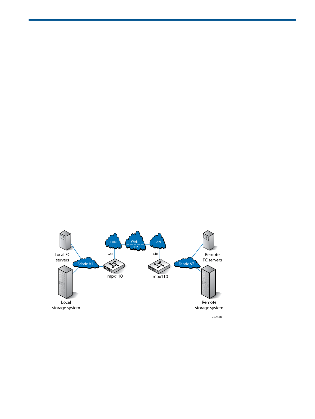
FCIP overview
FCIP enables connectivity between geographically dispersed FC devices over an IP network. To
deploy FCIP, two mpx110 gateways are required. Each gateway is configured for FCIP and
connected to a fabric. The gateways are connected to each other through an IP network
(LAN/WAN). For more information, see Figure 1 (page 9).
Local FC devices need no additional hardware or software to access remote FC devices using the
mpx110 deployed for FCIP.
Figure 1 FCIP overview
Using FCIP to encapsulate FC packets
With FCIP, gateways transport FC frames over an IP network. From the perspective of the local
and remote fabrics, the FC devices accessed through the gateways appear to be part of one unified
fabric. This effect is possible because FC traffic is carried over the IP network in such a way that
the FC fabric and all FC devices on the fabric are unaware of the presence of the IP network.
Once configured, FCIP instances on each gateway become active and establish their connectivity
through the IP network. The FC devices in the local fabric access the FC devices in the remote
fabric using FC frames. The FC frames are encapsulated in IP packets by the local gateway and
then transmitted to the remote gateway. The remote gateway strips the IP packet data and passes
only the FC frames to the remote FC devices.
The gateways deployed for FCIP are configured to use TCP, which uses standard TCP flow control
and error recovery algorithms.
FCIP overview 9
Page 10
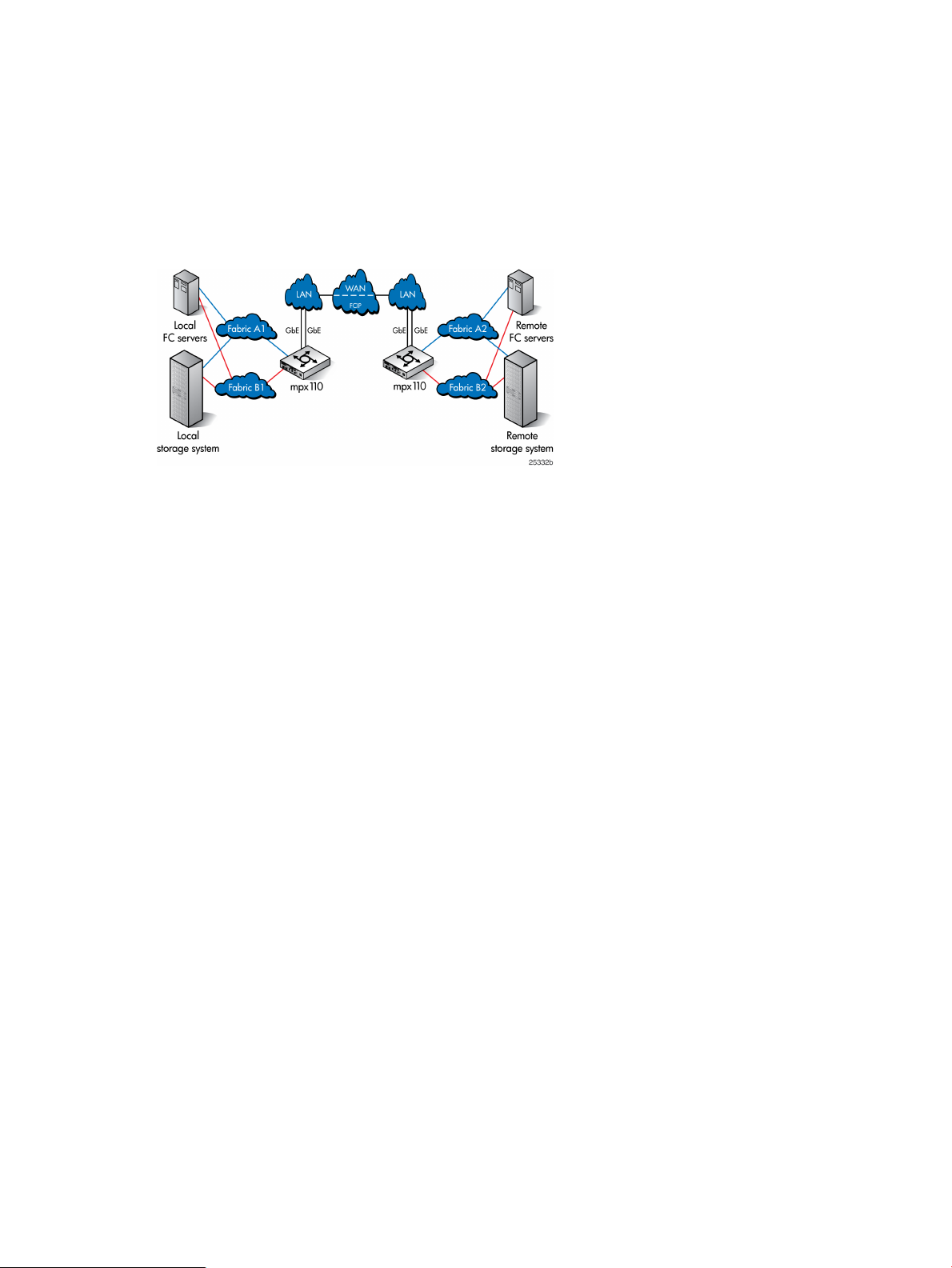
Redundant FCIP network structure example
In a high-availability FCIP configuration, such as between pairs of mpx110 gateways and two
independent IP networks that provide full redundancy, a loss of connectivity that occurs through
one of the IP networks does not result in a loss of connectivity between the fabrics. See FCIP fully
redundant, high-availability configuration.
Figure 2 FCIP fully redundant, high-availability configuration
10 Overview
Page 11
2 Configuration rules and guidelines
This chapter includes mpx110 supported configurations, rules and guidelines for the configurations,
and IP performance information.
Supported configurations
The mpx110 supports the following configurations:
• One pair of gateways with single-path connectivity (page 11)
• One pair of gateways with redundant fabrics (page 12)
• One pair of gateways, two long-distance links (page 12)
• Redundant pairs of gateways, one long-distance link (page 12)
• Redundant pairs of gateways, two long-distance links (page 13)
• Redundant pairs of gateways, fully redundant long-distance links (page 13)
• Highly redundant pairs of gateways, two long distance links (page 13)
• Highly redundant pairs of gateways, fully redundant long-distance links (page 14)
• Basic configuration, MPX200 FCIP with remote IP Distance Gateway (mpx110) (page 14)
• mpx110 FCIP with B-series Integrated Routing (page 15)
• mpx110 IP Distance Gateway FCIP with C-series IVR (page 16)
• HP Continuous Access EVA 3-site configuration with four gateways (page 17)
• HP Continuous Access EVA 3-site configuration with six gateways (page 17)
• HP Continuous Access EVA 3-site configuration with eight gateways (page 19)
Figure 3 One pair of gateways with single-path connectivity
Supported configurations 11
Page 12
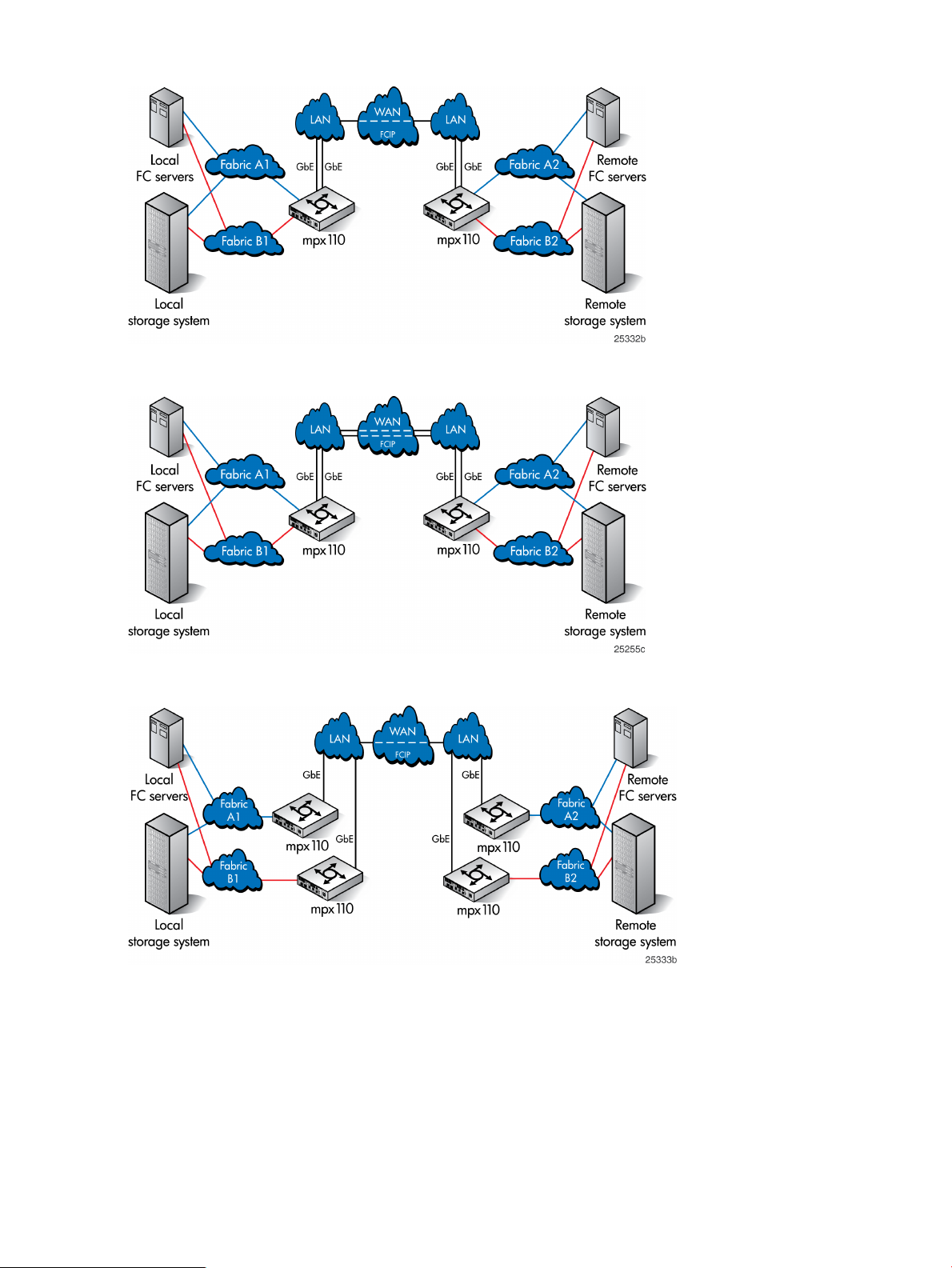
Figure 4 One pair of gateways with redundant fabrics
Figure 5 One pair of gateways, two long-distance links
Figure 6 Redundant pairs of gateways, one long-distance link
12 Configuration rules and guidelines
Page 13
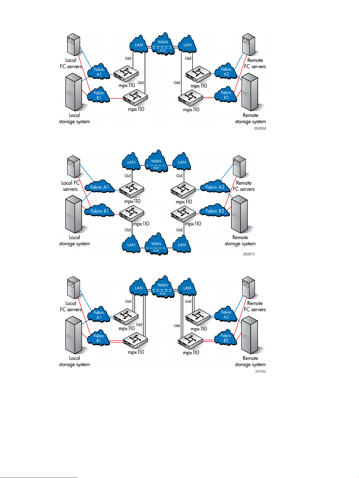
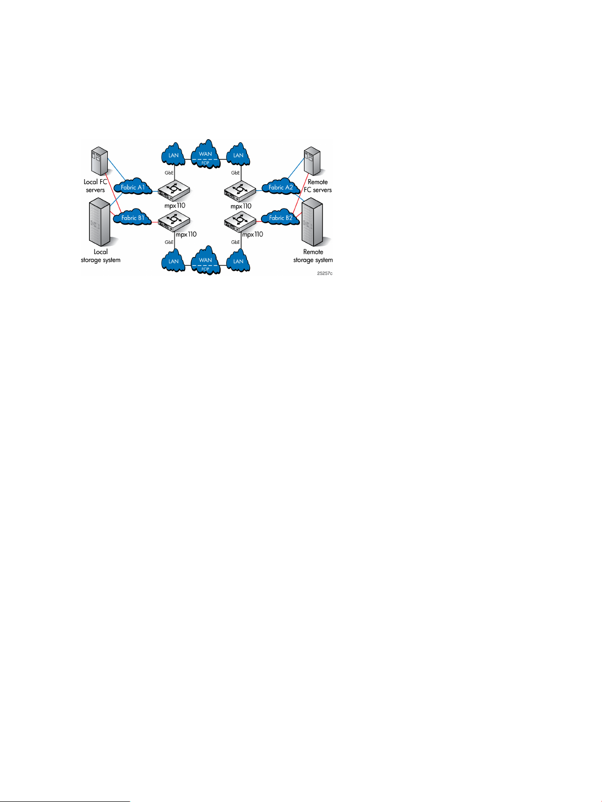
Figure 7 Redundant pairs of gateways, two long-distance links
Figure 8 Redundant pairs of gateways, fully redundant long-distance links
Figure 9 Highly redundant pairs of gateways, two long-distance links
Supported configurations 13
Page 14
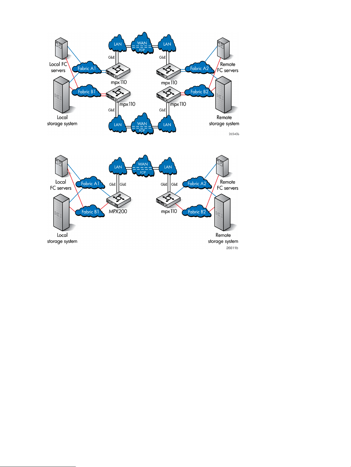
Figure 10 Highly redundant pairs of gateways, fully redundant long-distance links
Figure 11 Basic configuration, MPX200 FCIP with remote IP Distance Gateway (mpx110)
14 Configuration rules and guidelines
Page 15
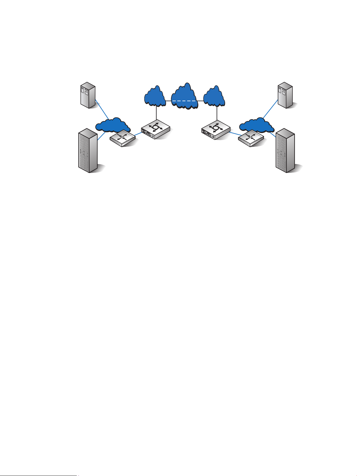
Figure 12 shows a configuration using the mpx110 with FCIP and B-series switches with Integrated
WAN
FCIP
LAN LAN
GbE GbE
26626a
Fabric A2
Fabric A1
Local
storage system
Remote
storage system
Local FC
servers
Remote
FC servers
FC1
FC2
GE1
GE2
MGMT
IOIOI
!
HP StorageWorks
mpx100
mpx110
FC1
FC2
GE1
GE2
MGMT
IOIOI
!
HP StorageWorks
mpx100
mpx110
EX
E
Routing. This provides fabric isolation between the local and remote fabrics, enabling device access
without merging the fabrics. This can be implemented in all supported mpx110 FCIP configurations
using B-series Fibre Channel switches with Integrated Routing or B-series routers configured for
Fibre Channel routing.
Figure 12 mpx110 FCIP with B-series Integrated Routing
Supported configurations 15
Page 16
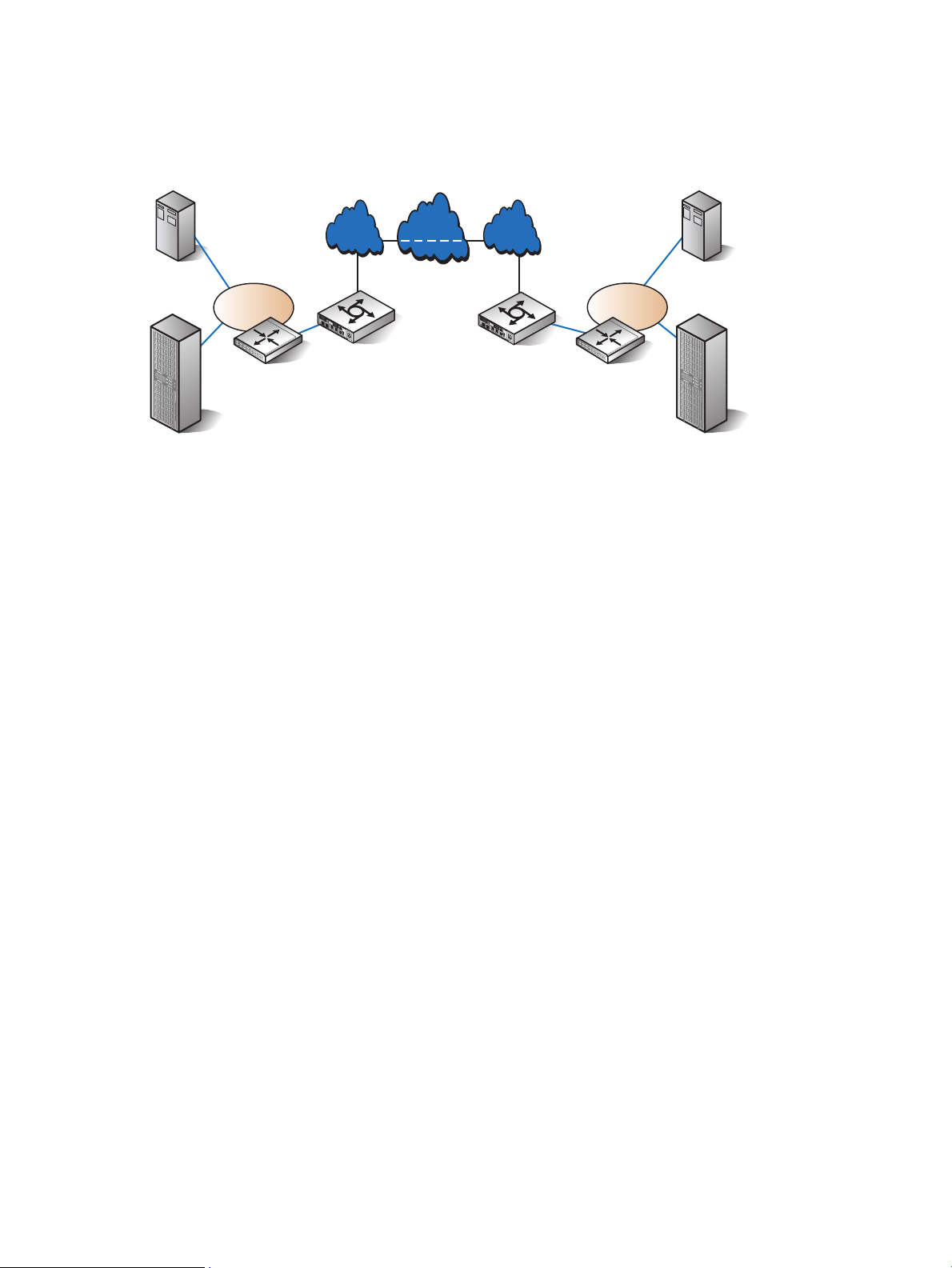
Figure 13 shows a configuration using the mpx110 with FCIP and C-series switches with IVR. This
VSAN A1
WAN
FCIP
LAN LAN
GbE GbE
26637a
Local
storage system
Remote
storage system
Local FC
servers
Remote
FC servers
FC1
FC2
GE1
GE2
MGMT
IOIOI
!
HP StorageWorks
mpx100
m p x 11 0
FC1
FC2
GE1
GE2
MGMT
IOIOI
!
HP StorageWorks
mpx100
m p x 11 0
E
E
VSAN A2
provides fabric isolation between the local and remote fabrics, allowing device access without
merging the fabrics. This can be implemented in all supported mpx110 FCIP configurations using
C-series Fibre Channel switches with IVR.
Figure 13 mpx110 IP Distance Gateway FCIP with C-series IVR
16 Configuration rules and guidelines
Page 17
HP Continuous Access P6000/EVA 3-site configurations
This section describes the following HP Continuous Access P6000/EVA 3-site configurations:
• HP Continuous Access EVA 3-site configuration with four gateways (page 17)
• HP Continuous Access EVA 3-site configuration with six gateways (page 17)
• HP Continuous Access EVA 3-site configuration with eight gateways (page 19)
• (page 20)
The first three configurations provide a fan-in or fan-out relationship between the sites. The fourth
configuration provides a peer-to-peer relationship between all sites.
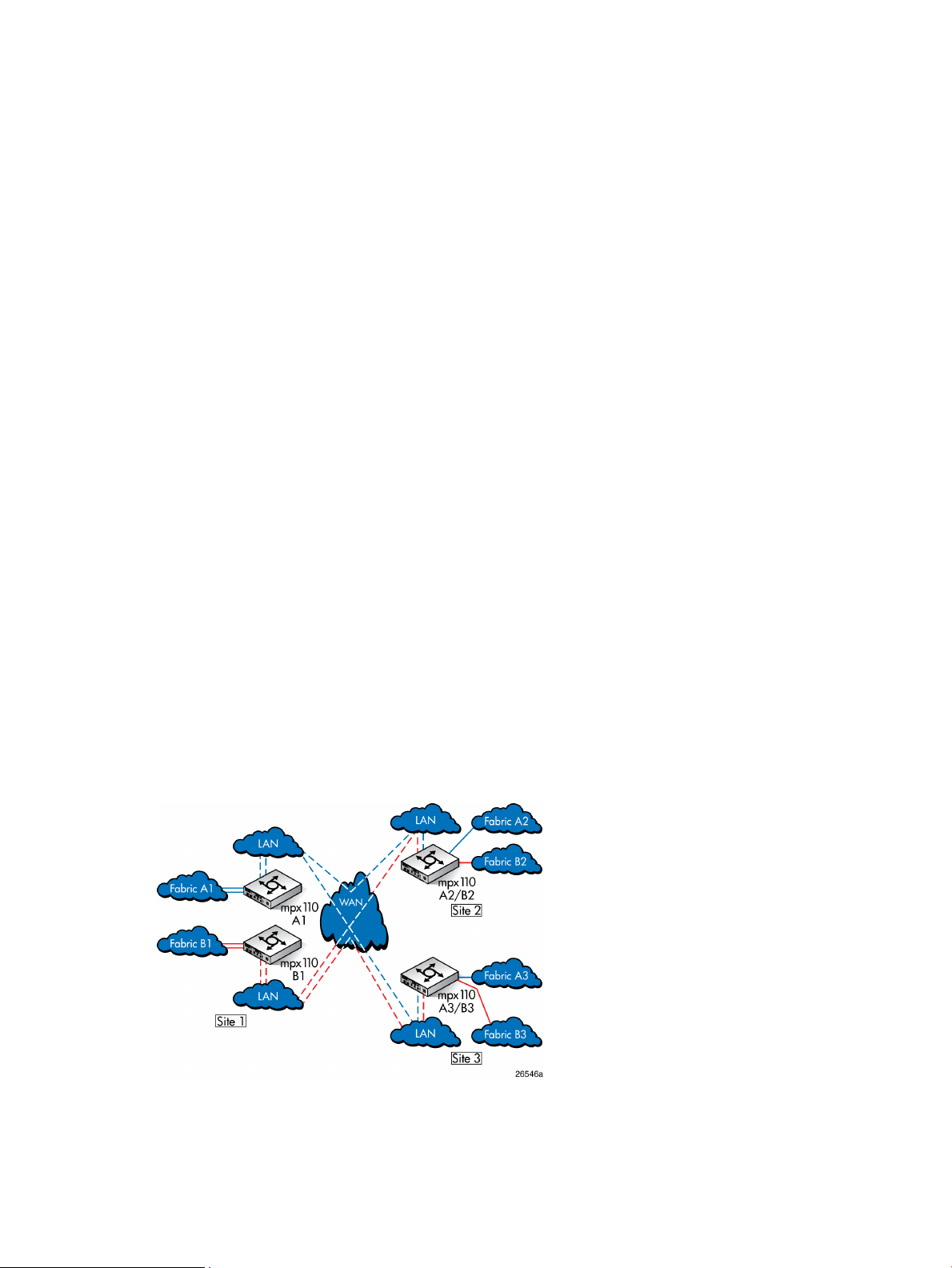
Figure 14 (page 17) shows connectivity for three sites using four mpx110 gateways, which
implements the minimum-level and lowest-cost connectivity for a 3-site configuration. Figure 15 (page
18) shows additional connectivity and redundancy using six mpx110 gateways. Figure 16 (page
19) shows the highest level of 3-site connectivity using eight mpx110 gateways.
Figure 17 (page 20) is similar to Figure 15 (page 18), with additional connectivity to allow for
replication between Site 2 and Site 3.
The following configuration rules apply to Figure 14 (page 17) through Figure 16 (page 19)
(fan-in/fan-out relationships):
• For Site 1, Site 2 or Site 3 can function as the remote site.
• For Site 2 or Site 3, Site 1 can function as the remote site.
• Replication between Site 2 and Site 3 is not supported.
The following configuration rules apply to Figure 17 (page 20) (peer-to-peer relationship):
• For Site 1, Site 2 or Site 3 can function as the remote site.
• For Site 2, Site 1 or Site 3 can function as the remote site.
• For Site 3, Site 1 or Site 2 can function as the remote site.
3-site configuration with four mpx110 gateways
The configuration shown in Figure 14 (page 17) provides long-distance link redundancy between
all three sites.
Figure 14 HP Continuous Access P6000/EVA 3-site configuration with four mpx110 gateways
3-site configuration with six mpx110 gateways
The configuration shown in Figure 15 (page 18) provides the same long-distance link redundancy
as the configuration shown in Figure 14 (page 17), with the addition of redundant mpx110
gateways at sites 2 and 3.
HP Continuous Access P6000/EVA 3-site configurations 17
Page 18
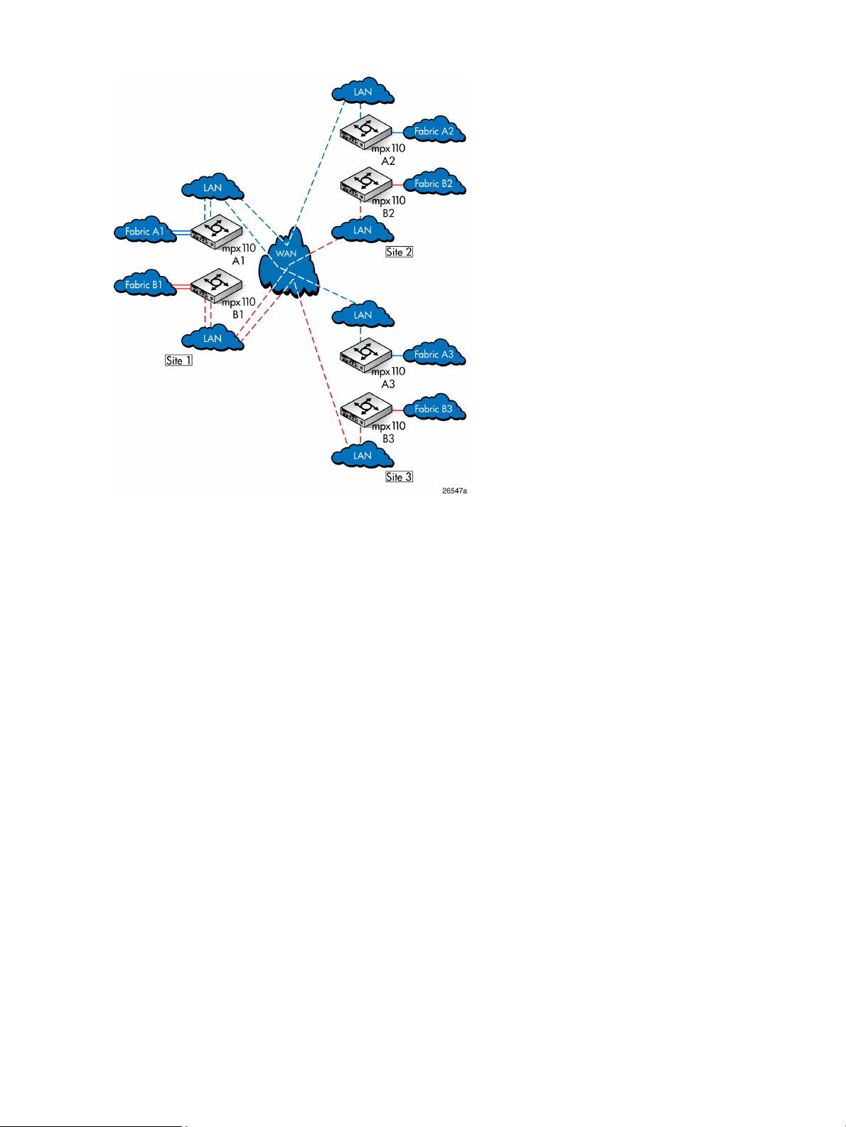
Figure 15 HP Continuous Access P6000/EVA 3-site configuration with six mpx110 gateways
18 Configuration rules and guidelines
Page 19
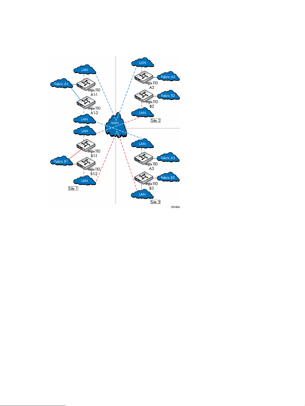
3-site configuration with eight mpx110 gateways
The configuration shown in Figure 16 (page 19) provides the highest 3-site redundancy, with a
dedicated mpx110 pair for all long-distance links to all three sites.
Figure 16 HP Continuous Access P6000/EVA 3-site configuration with eight mpx110 gateways
HP Continuous Access P6000/EVA 3-site configurations 19
Page 20
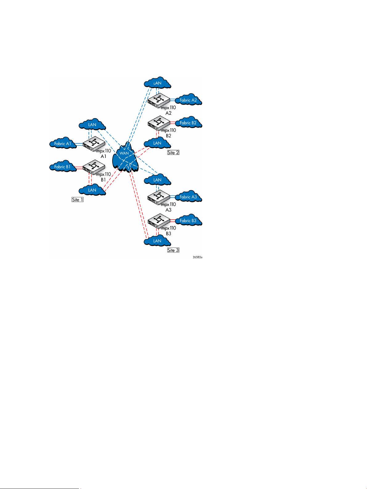
3-site configuration with six gateways and full inter-site connectivity
Figure 17 (page 20) provides long-distance link redundancy and full connectivity between all three
sites.
Figure 17 HP Continuous Access P6000/EVA 3-site configuration with six gateways, full peer-to-peer
connectivity
20 Configuration rules and guidelines
Page 21

Configuration rules and guidelines
The following sections define the configuration rules for using the mpx110 gateways for FCIP.
General configuration rules
The following general configuration rules apply:
• All mpx110 configurations require a minimum of two mpx110 gateways, or one mpx110
and one MPX200 Multifunction Router with an FCIP license, one local and one remote,
connected through an IP network.
• The mpx110 gateway must connect to another mpx110 or an mpx200 Multifunction Router
with an FCIP license. HP does not support FCIP connectivity between other gateway models.
• The mpx110 gateway is supported for FCIP extension with HP P9000 and P6000 Continuous
Access (see EVA storage system rules and guidelines (page 21) and XP storage system rules
and guidelines (page 22)), and P10000/3PAR Remote Copy software.
NOTE: For current support, see SPOCK at http://www.hp.com/storage/spock. You must sign
up for an HP Passport to enable access.
Operating system and multipath support
The mpx110 gateway is supported using FCIP with all operating systems and multipath software
supported by HP. For more information, see the HP SAN Design Reference Guide, available at
http://www.hp.com/go/SDGManuals.
P6000/EVA storage system rules and guidelines
Observe the following P6000/EVA storage system rules and guidelines:
• P6350/P6300/P6550/P6500
• The mpx110 gateway configured for FCIP is supported for use with the following HP Continuous
Access P6000/EVA storage systems:
◦ EVA4400/4400 with embedded switch
◦ EVA4000/4100/6000/6100/8000/8100
◦ EVA6400/8400
• The mpx110 gateway is supported for use in all HP-supported P6000 Continuous Access
configurations, including the standard two-fabric, five-fabric, and six-fabric configurations.
• HP P6000 Continuous Access supports RCS and non-RCS LUNs with FCIP extension.
• HP mpx110 gateway supports the minimum IP bandwidth/maximum DR groups.
Table 1 (page 22) defines the minimum IP bandwidth and maximum EVA DR groups for EVA XCS
and VCS.
Configuration rules and guidelines 21
Page 22

Table 1 Minimum IP bandwidth and maximum DR groups
Gateway pair
Minimum IP bandwidth and maximum DR groups
1
Single or shared IP link latency (0 to 100 ms one-way)Dual fabric latency (0 to 100 ms one-way)
IP Distance
Gateway
(mpx110)
1
1 Gb/s IP bandwidth can have up to 128 DR groups with VCS 4.x, and up to 256 DR groups with XCS.
Minimum: At least 2 Mb/s for 1 DR group
Recommended: At least 5 Mb/s for 1 to 5 DR groups
Minimum: At least 4 Mb/s for 1 DR group
Recommended: At least 10 Mb/s for 1 to 5 DR groups
P6000/EVA storage system software
The mpx110 gateway is supported with current P6000/EVA storage software applications such
as HP P6000 Continuous Access, Command View EVA, Business Copy, SSSU, and Replication
Solutions Manager.
P9000/XP storage system rules and guidelines
Observe the following P9000/XP storage system rules and guidelines:
• Supported P9000/XP models are P9500/XP24000/20000 and XP12000/10000, with
supported firmware levels. For more information, see SPOCK at http://www.hp.com/storage/
spock.
• The mpx110 gateway configured for FCIP is supported for use with P9000/XP Continuous
Access Sync, Async, and Journal.
• The mpx110 gateway is supported for use in all HP-supported P9000/XP Continuous Access
FCIP configurations. For more information, see the P9000/XP Continuous Access documentation
and the HP SAN Design Reference Guide, available at http://www.hp.com/go/SDGManuals.
• A P9000/XP storage system requires a minimum IP bandwidth of 16 Mb/s per path. The
maximum latency is 100 ms round-trip.
P9000/XP storage system software
The mpx110 gateway is supported with current versions of P9000/XP storage software applications,
such as XP Continuous Access, Command View XP, Continuous Access Journal XP, Business Copy
XP, and XP Array Manager.
Fibre Channel switch and firmware support
The mpx110 is compatible with the following Fibre Channel switches:
• B-series 8 Gb/s, 4 Gb/s, and 2 Gb/s Fibre Channel switches
• C-series 8 Gb/s, 4 Gb/s, and 2 Gb/s Fibre Channel switches
• H-series 8 Gb/s Fibre Channel switches
NOTE: For current support, see SPOCK at http://www.hp.com/storage/spock. You must
sign up for an HP Passport to enable access.
FC switch requirements
The following additional B-series, C-series, and H-series FC switch requirements must be observed:
• Local and remote mpx110 gateway pairs must be connected to the same Fibre Channel switch
product line series.
• The maximum distance between an mpx110 and a Fibre Channel switch is 300 meters at 2
Gb/s.
NOTE: The mpx110 Fibre Channel ports operate at 2 Gb/s.
22 Configuration rules and guidelines
Page 23

IP network requirements
HP requires that the following standards be met for the IP network:
• Supported network protocols are TCP/IP IPv4 and IPv6 Ethernet 1,000 Mb/s.
See EVA storage system rules and guidelines (page 21) and XP storage system rules and
guidelines (page 22) for minimum IP bandwidth requirements.
• For mpx110 IP data—Local and remote pairs are supported for up to 100 ms of IP network
delay one-way, or 200 ms round-trip for HP Continuous Access P6000. HP requires dedicated
IP bandwidth (see Table 2 (page 24)). For P9000 Continuous Access, the maximum distance
and delay is based on the replication mode. See “P9000/XP and VA storage system rules”
in the HP SAN Design Reference Guide.
• For mpx110 IP management—LAN and WAN are supported.
Configuration rules and guidelines 23
Page 24

Table 2 Network requirements for the mpx110 with XCS and VCS
DescriptionSpecification
Bandwidth
1
Must be dedicated to the HP Continuous Access storage replication function.
There is no support for dynamic pacing of the gateway.
Maximum number of DR groups
See Table 1 (page 22) for minimum supported bandwidth based on the
average packet-loss ratio and one-way intersite latencies.
1,500 bytesMTU of the IP network
Maximum latency
1
P6000/EVA: 100 ms one-way or 200 ms round-tripP9000/XP: 50 ms one-way
or 100 ms round-trip
Average packet-loss ratio
2
Low-loss network: 0.0012% average over 24 hoursHigh-loss network: 0.2%
average over 24 hours; must not exceed 0.5% for more than 5 minutes in a
2-hour window
3
1
Pre-existing restriction
2
A high packet-loss ratio indicates the need to retransmit data across the intersite link. Each retransmission delays
Must not exceed 10 ms over 24 hoursLatency jitter
transmissions queued behind the current packet, thus increasing the time to complete pending transactions.
3
Latency jitter is the difference between the minimum and maximum values, and indicates how stable or predictable the
network delay. The greater the jitter, the greater the variance in the delay, which lowers the performance predictability.
24 Configuration rules and guidelines
Page 25

IP performance tuning
The mpx110 supports Fibre Channel service at transmission rates of 1 Gb/s or 2 Gb/s with a
maximum frame size of 2,148 bytes. It supports Ethernet service at transmission rates of 1,000 or
100 Mb/s with an MTU size between 1,000 and 9,000 bytes (jumbo frames). Related performance
characteristics include the following:
• Distance (page 25)
• Bandwidth per route (page 25)
• Latency (page 25)
• MTU/Jumbo frames (page 25)
• Compression (page 26)
• TCP Window size/scaling performance tuning (page 26)
Distance
Consider the physical distance between the mpx110 gateways. This is usually measured in RTT.
The RTT can be anywhere from less than 1 millisecond to as great as 200 milliseconds.
Bandwidth per route
Bandwidth is a measure of the volume of data that can be transmitted at a given transmission rate.
WAN data rates range from 1.5 Mb/s (T1) to greater than 600 Mb/s (OC-12). The proper
mpx110 bandwidth setting is determined based on the bandwidth available for each FCIP route,
irrespective of the total bandwidth and physical speed of the link.
To determine the proper mpx110 bandwidth setting, start with the total bandwidth of the WAN
link. Adjust this number based on the guaranteed allocated FCIP bandwidth, then further adjust
this number if the number of FCIP routes configured is greater than one. For example, if the WAN
link is 45 Mb/s, and 15 Mb/s is allocated to network traffic, the remaining 30 Mb/s is available
for FCIP. If in this example the mpx110 is configured for two routes, based on the 30 Mb/s total
bandwidth available for FCIP, you would set the mpx110 bandwidth parameter to 15, the available
bandwidth for each FCIP route.
HP P9000 and P6000 Continuous Access replication solutions require dedicated bandwidth for
the intersite link. If other applications share the intersite link, some method of QoS must be used
to ensure that the replication application has uncontested access to the allocated bandwidth.
NOTE: Setting the bandwidth per route parameter higher than the actual bandwidth available
for each route results in a decrease in performance; the optimal setting matches the bandwidth
per route setting to the actual bandwidth available to each FCIP route.
Latency
Latency is the amount of time a packet takes to traverse the network from source to destination.
MTU/Jumbo frames
For MTU size there are 3 settings, Normal (1500 bytes), Jumbo (9000 bytes) and Other, where
you are then prompted for a value between 1000 and 9000.
• Normal: Typically MTU should be set to the default of 1500; rarely do WAN networks support
MTU sizes greater than 1500.
• Jumbo - Jumbo frames can enhance the IP performance of the mpx110. Before enabling jumbo
frames, ensure that all switches in the IP path are configured for jumbo frames.
IP performance tuning 25
Page 26

NOTE: Jumbo frames are not supported for use with HP P9000 or P6000 Continuous Access.
• Other: Allows you to configure the MTU size to a value between 1000 and 9000 bytes.
Encryption products on the WAN link often add some number of additional bytes to each
packet, so it may be necessary to decrease the mpx110 MTU size setting to between 1450
and 1200. This accommodates the additional bytes, while maintaining a total MTU size of
1500 or less. Keeping the total MTU size to a maximum of 1500 ensures a single Fibre
Channel frame (2112 bytes) will fit within two Ethernet packets, resulting in optimal
performance.
Compression
The mpx110 integrates a software compression option. Enable compression for IP fabrics with an
RTT greater than or equal to 50 ms, or guaranteed WAN bandwidth of less than or equal to 45
Mb/s. See TCP window size recommendations (page 28) for compression options for specific
network rates and RTT.
TCP window size/scaling performance tuning
The mpx110 performance is maximized when properly configured. Knowing the RTT (distance)
between mpx110 gateways and the WAN effective data rate (connection type) allows the gateways
to be tuned for optimal performance. See (page 26).
Modifying the window size and scaling factor
The mpx110 window size can be set to a maximum of 32 KB. The scaling factor is used as a
multiplier to increase the window size above 32 KB. Modify the window size and scaling factor
in the mpx110 gateway pairs based on the WAN RTT and link speed. To determine the appropriate
window size setting, use the pre-populated tables or a formula.
If the recommended TCP window size scale factor for a given RTT and WAN link speed is not
shown in Table 4 (page 28) through Table 10 (page 31), use the following formula:
(RTT (ms) x link rate (Kb/s) x (1 byte/8 bits) = minimum window size (MWS)
Then, convert the MWS to a recommended scale factor by dividing it by the default window size
(32,768 bytes). Use Table 3 (page 27) to determine the scale factor.
26 Configuration rules and guidelines
Page 27

Table 3 TCP window size scale factors
Scale factorMWS scale result
00 to 2
12 to 4
24 to 8
38 to 16
416 to 32
532 to 64
664 to 128
7128 or greater
IP performance tuning 27
Page 28

TCP window size recommendations
Table 4 (page 28) through Table 10 (page 31) provide TCP window scaling factor and window
size settings for specific WAN environments.
NOTE: The TCP window size recommendations listed in Table 4 (page 28) through Table 10 (page
31) are based on low-loss networks (0.0012% average packet-loss ratio over 24 hours). For
higher-loss, longer-latency networks, you should reduce the recommended window size and scaling
factor by one setting to compensate for the increased number of packet retransmissions.
Table 4 T1 / DS-1: 1.554 Mb/s
Round-trip time
size (bytes)
Scaling factorTotal window
Compression
recommendations
ON164 K200
ON032 K100
ON032 K50
ON032 K25
ON032 K20
ON032 K15
ON032 K10
ON032 K5
ON032 K2.5
ON032 K1 or less
28 Configuration rules and guidelines
Page 29

Table 5 T3 / DS-3: 45 Mb/s
Round-trip time
size (bytes)
Table 6 DS-5: 400 Mb/s
Round-trip time
size (bytes)
Scaling factorTotal window
Scaling factorTotal window
Compression
recommendations
ON62 MB200
ON51 MB100
ON3256 K50
ON2128 K25
ON2128 K20
ON164 K15
ON164 K10
ON032 K5
ON032 K2.5
ON032 K1 or less
Compression
recommendations
ON74 MB200
ON74 MB100
ON74 MB50
OFF62 MB25
OFF51 MB20
OFF51 MB15
OFF4512 K10
OFF3256 K5
OFF2128 K2.5
OFF164 K1 or less
IP performance tuning 29
Page 30

Table 7 OC-1: 50 Mb/s
Round-trip time
size (bytes)
Table 8 100-BASE T: 100 Mb/s
Round-trip time
size (bytes)
Scaling factorTotal window
Scaling factorTotal window
Compression
recommendations
ON62 MB200
ON51 MB100
ON4512 K50
ON2128 K25
ON2128 K20
ON or OFF2128 K15
OFF164 K10
OFF032 K5
OFF032 K2.5
OFF032 K1 or less
Compression
recommendations
ON74 MB200
ON62 MB100
ON51 MB50
ON4512 K25
ON3256 K20
ON or OFF3256 K15
OFF2128 K10
OFF164 K5
OFF032 K2.5
OFF032 K1 or less
30 Configuration rules and guidelines
Page 31

Table 9 OC-3: 150 Mb/s
Round-trip time
size (bytes)
Table 10 OC-6: 311 Mb/s
Round-trip time
size (bytes)
Scaling factorTotal window
Scaling factorTotal window
Compression
recommendations
ON74 MB200
ON62 MB100
ON51 MB50
ON or OFF4512 K25
ON or OFF4512 K20
OFF3256 K15
OFF3256 K10
OFF2128 K5
OFF164 K2.5
OFF032 K1 or less
Compression
recommendations
ON74 MB200
ON74 MB100
ON62 MB50
OFF51 MB25
OFF51 MB20
OFF51 MB15
OFF4512 K10
OFF3256 K5
OFF2128 K2.5
OFF164 K1 or less
IP performance tuning 31
Page 32

Table 11 OC-12 and above: 621 Mb/s
Round-trip time
size (bytes)
Scaling factorTotal window
Compression
recommendations
ON74 MB200
ON74 MB100
ON74 MB50
OFF62 MB25
OFF62 MB20
OFF52 MB15
OFF51 MB10
OFF4512 K5
OFF3256 K2.5
OFF164 K1 or less
32 Configuration rules and guidelines
Page 33

3 Installation and upgrades
This chapter contains the information needed to install, configure, and upgrade the mpx110.
Verifying mpx110 requirements
Obtain the following (one of each, unless otherwise noted) for the local and remote site:
• HP IP Distance Gateway (mpx110), Part Number: AG680A
• HP P9000 or P6000 Continuous Access software or P10000/3PAR Remote Copy software
EVA4400/4400 with embedded switch, EVA4000/4100/6000/6100/8000/8100,
EVA6400/8400, P6350/P6300/P6550/P6500, or
P9500/XP24000/20000/12000/10000 storage system or P10000/3PAR V-Class, F-Class,
T-Class storage systems
• FC fabrics consisting of HP B-series, C-series, or H-series switches
• Cat 5e network cable, two per site
• Optical SFPs and FC cables, two per site
Additional optional equipment (one of each, unless otherwise noted) for the local and remote site:
• HP IP Distance Gateway Upgrade (mpx110 for redundancy), Part Number: AG681A
• Optical SFPs and FC cables, two per site
NOTE: For the latest information about the minimum system requirements, see the HP IP Distance
Gateway release notes, available at http://www.hp.com/support/manuals. Under Storage, select
Storage Networking, and then under Routers/Gateways/Multiplexers, select HP IP Distance
Gateway.
Verifying mpx110 requirements 33
Page 34

Pre-installation checklist
Before starting the configuration process, contact your System Administrator for the following
mpx110 parameters:
• Symbolic Name of the mpx110
• IP address, subnet mask and gateway for the mpx110 management port (if not using DHCP)
• IP address, subnet mask and gateway for the GE1 port
• IP address of the remote mpx110 that connects to the GE1 port
• IP address, subnet mask and gateway for the GE2 port (if applicable)
• IP address of the remote mpx110 that connects to the GE2 port (if applicable)
• FCIP link parameters (specifically, Guaranteed Bandwidth, Round-Trip-Delay, Quality Of
Service, and VLAN/Priority)
For more information, see (page 41).
• mpx110 serial console cable adapter
• HP mpx Manager software (optional)
• The default TCP port used by the mpx110 is 3225. To ensure that the FCIP link is formed
correctly, make sure that any firewalls have port 3225 unblocked before connecting the
mpx110s.
Rack mounting the mpx110
WARNING! Mount the mpx100/100b in the rack so that the weight is evenly distributed. An
unevenly loaded rack can become unstable possibly resulting in equipment damage or personal
injury.
This product is supplied with a three-wire cable and plug for the user's safety. Use this power cable
in a properly grounded outlet to avoid electrical shock. An electrical outlet that is not correctly
wired could place hazardous voltage on metal parts of the switch chassis. It is the responsibility
of the customer to ensure the outlet is correctly wired and grounded to prevent electrical shock.
If the chassis is installed in a closed or multi-rack assembly, the operating temperature of the rack
environment may be greater than the ambient temperature, Be sure to install the chassis in an
environment that is compatible with the maximum ambient rated temperature.
You need a Phillips head screwdriver to rack mount the mpx110. You also need to make sure that
the operating temperature inside the rack enclosure does not exceed the maximum rated ambient
temperature (70° C), especially if the mpx110 is mounted in a closed or multi-unit rack assembly.
1. Assemble two slide brackets (right and left) on the back ends of the C-Shelf, using the four
hole nut plates:
NOTE: The rear of the C-Shelf is the end without the knurled thumbscrews.
a. Mount the C-Shelf with the open side up.
b. Fit the slide bracket along the 1U side at the back of the C-Shelf with its screw hole tab
pointing outboard and its lip supporting the C-Shelf. Mount both right-hand and left-hand
slide brackets.
c. Attach the nut plate outside the slide bracket with the dimpled threaded holes pointing
outboard.
34 Installation and upgrades
Page 35

d. Place two screws (10-32 Pan 0.625 XRCS) through the two holes at the back of the
C-Shelf, through the slide plate slots and loosely into the front two threaded holes of the
nut plate.
e. Repeat steps a through d with the opposite hand slide bracket.
2. Install the C-Shelf assembly into the rack:
a. Locate a clear 1U area space within the rack.
NOTE: The 1U space in a rack includes three rail mounting holes; however, the rack
holes are not evenly spaced. For best installation the C-Shelf can be centered in a 1U
space. To locate the center, find a hole that is 5/8" on center from the hole immediately
above and below. The two holes above and below this center are only 1/2" on center
from their adjacent holes.
b. At the front of the rack, in the center mounting holes, install two nuts (KEPs 10-32, 0.375AF
CSZ EXT).
c. Carefully supporting the C-Shelf assembly, loosely thread the knurled thumbscrews through
the rack into the two nuts just installed.
d. Go to the back of the rack and position a slide bracket next to the corresponding holes
at the back of the rack. Slide the bracket to the rear until the threaded screw hole tabs
are flush with the inside of the rack rail.
e. Insert two screws (10-32 Pan 0.325 XRCS screws) through the rack rail into the threaded
screw hole tab and tighten loosely.
f. Repeat step e with the other side of the C-Shelf assembly.
g. Tighten all four screws (10-32 Pan 0.625 XRCS screws) at the rear of the C-Shelf assembly.
h. Tighten the front two knurled thumbscrews.
i. Tighten the two screws (10-32 Pan 0.625 XRCS screws) at each side of the back of the
C-Shelf assembly.
3. Install the mpx110 into one of the two available positions in the C-Shelf:
a. As the mpx110 slides in there are two tabs at the front and rear that catch and ensure
that the mpx110 is firmly seated to the C-Shelf assembly. Take care to ensure that the
mpx110 is engaged in all four tabs. To ensure that all four of the tabs engage, you may
need to hold both the mpx110 and the C-Shelf assembly as you slide it in the last inch.
NOTE: The front of the mpx110 is the end with the connections and faces the rear of
the equipment rack. The mpx110 slides in from the front of the equipment rack.
b. Once the rear of the mpx110 is flush with the front of the C-Shelf assembly and all four
clips are engaged, the bezel can be snapped on the front.
Installing the SFPs
You will need an SFP transceiver for each of the FC ports that connect to an FC switch.
To install the SFPs:
1. Align the SFP transceiver so that the key is oriented correctly to the port. Transceivers are
keyed so that they can only be inserted one way.
2. Insert the transceiver into the port.
3. Press gently until the transceiver snaps into place.
Management
The GUI application and CLI execute on a management workstation that provides for the
configuration, control, and maintenance of the mpx110. Supported platforms include Microsoft
Windows, Solaris, and Linux. The GUI application is installed and executed on the workstation.
Installing the SFPs 35
Page 36

The mpx110 supports the following management interfaces:
• mpx Manager GUI—Executes on a management workstation
• CLI—Executes on the mpx110 and is accessed using Telnet or the serial port (see Command-line
interface (page 80))
• SNMP—Provides mpx110 status, traps, and alerts (see Simple Network Management
Protocol (page 132))
Installing the management application
You can manage the mpx110 using the HP mpx Manager as a standalone application. The mpx
Manager software is available in the HP IP Distance Gateway software kit. The Linux kit is provided
in .tar format; the Windows kit is provided as a .zip file. The kits are available at http://
h18006.www1.hp.com/storage/networking/index.html.
Table 12 (page 36) lists the requirements for the management servers running the HP mpx Manager.
Table 12 mpx Manager server requirements
RequirementComponent
Windows 2003, 2008 or XPOperating system
MAC OS X
Linux
• SUSE LINUX Enterprise Server 10 (x86)
• SUSE LINUX Enterprise Server 9 (x86)
• SUSE LINUX Enterprise Server 8 (x86)
• Red Hat Enterprise Linux 3 Update 5 (x86) minimum
• Red Hat Enterprise Linux 4 (x86)
• Red Hat Enterprise Linux 5 (x86)
Internet browser
256 MB or moreMemory
150 MB per installationDisk space
500 MHz or fasterProcessor
CD-ROM drive, RJ-45 Ethernet port, RS-232 serial port (optional)Hardware
• Microsoft Internet Explorer 5.0 and later
• Netscape Navigator 4.72 and later
• Mozilla 1.02 and later
• Safari Java 2 Runtime Environment to support web applet
36 Installation and upgrades
Page 37

HP mpx Manager for Windows
You can install HP mpx Manager on a Windows server. To install the HP mpx Manager application
from the HP IP Distance Gateway installation file:
1. Close all programs currently running, and then unzip the executable file to the system.
2. Double-click the executable to start the installation.
HP mpx Manager for Linux
This section describes how to install HP mpx Manager on a Linux server.
NOTE: In the following procedure, replace n.n.nn and n.n.nnbnnn with a file name (for
example, 2.0.30 and 2.0.30b112).
1. Download the hpmpx_n.n.nn_linux_install.tar file from http://
h18006.www1.hp.com/storage/networking/index.html. The .tar file contains the .bin
file and a GUI install README file.
2. Unpack the file to a temporary directory. For example:
tar -zxvf hpmpx_n.n.nn_linux_install.tar
3. Enter the following to start the install:
./hpmpxn.n.nnbnn_linux_install.bin.
A chmod may be necessary prior to execution.
4. Follow the installation instructions on the screen and note the installation location. The default
directory is /opt/Hewlett-Packard/mpxManager.
Setting mpx110 management port parameters
NOTE: If you are using Telnet to configure the mpx110 for the first time, your workstation IP
address must be 10.0.0.x, where x is a number other than 1, and the subnet mask is 255.0.0.0.
To set the initial mpx110 configuration parameters:
1. Connect the mpx110 management port to a workstation to configure the initial mpx110
parameters. You can connect the mpx110 management port to an IP switch or hub, directly
to the workstation with an Ethernet crossover cable to the management port, or to the RS-232
port with a serial cable.
NOTE: If connecting to the mpx110 serial port, the terminal settings are 115200 baud, 8
bit, 1 stop bit, no parity, and no flow control.
2. Attach one end of the AC power cord to the mpx110 and the other end to the PDU.
3. Verify that the Heartbeat LED is flashing (once per second) and that the System Fault LED does
not illuminate. Figure 18 (page 37) shows the location of the ports and LEDs on the mpx110.
Figure 18 mpx110 ports and LEDs
Management 37
Page 38

See Diagnostics and troubleshooting (page 48) for a description of the LED fault indications.
4. Telnet to the mpx110 using IP address 1.0.0.1, or use a terminal emulation program (serial
cable) from your workstation (see Figure 19 (page 38)):
a. Enter guest at the login prompt.
b. Enter password at the password prompt.
NOTE: HP recommends changing the mpx110 guest password after logging in.
Figure 19 Setting IP addressing using Telnet
5. Enter admin start at the mpx110 prompt.
6. Enter the default password, config.
NOTE: HP recommends that you change the mpx110 Admin password after logging in.
7. Enter the command set mgmt to set initial parameters.
8. Follow the on-screen prompts to define the following parameters (or press Enter to accept
default parameters):
• Mode (HP highly recommends using static address, Option 0)
• IPv4/IPv6 address (Because the FCIP ports require dedicated bandwidth, HP recommends
that the IP address for the management port be in a different subnet than the FCIP ports.)
• Subnet mask
• Default gateway or router
The management port is now configured with the appropriate IP address and network
parameters.
IMPORTANT: At this point, the Telnet session terminates. To restart the Telnet session, use
the IP address you just assigned to the management port.
38 Installation and upgrades
Page 39

Configuring Fibre Channel switch settings for the mpx110
This section provides HP Fibre Channel switch parameters. Modify the switch settings listed below
based on the switch product line used. All settings apply to HP P9000 and P6000 Continuous
Access unless noted otherwise.
B-series Fibre Channel switch parameters
Execute the commands in Table 13 (page 39) for all switches that will use the FCIP link.
Table 13 Settings for B-series switches
HP storage systemCommand
B-Switch# switchdisable
B-Switch# iodset
B-Switch# aptpolicy [1 or 3] (See NOTE below.)
B-Switch# portcfgislmode [slot/port],1
(Set for all mpx110 connected switch ports, regardless of the storage type)
B-Switch# portcfggport [slot/port],1
(Set for all mpx110 switch ports)
B-Switch# switchenable
P6000/EVA
P9000/XP
P10000/3PAR
Configuring Fibre Channel switch settings for the mpx110 39
Page 40

C-series Fibre Channel switch parameters
Execute the commands in Table 14 (page 40) for each VSAN that will use the FCIP link. Enter
configuration commands based on the storage system, one per line in the order listed below.
Table 14 Settings for C-series switches
HP storage systemCommand
C-Switch# config
C-Switch(config)# in-order-guarantee VSAN #(where # stands for all
VSANs that use the FCIP link)
C-Switch(config)# vsan database
C-Switch(config-vsan-db)# vsan # loadbalancing [src-dst-id]
or [src-dst-ox-id](See NOTE below.)(where # stands for all VSANs that use
the FCIP link)
C-Switch(config-vsan-db)# exit
C-Switch(config)# exit
C-Switch# copy run start
P6000/EVA
P9000/XP
P10000/3PAR
NOTE: For P6000 Continuous Access:
• For B-series, specify 1 for port-based routing (all XCS versions) or 3 for exchange-based routing
(XCS 09534000 or later).
• For C-series, specify src-dst-id for port-based routing (all XCS versions) or src-dst-ox-id for
exchange-based routing (XCS 09534000 or later).
• For port-based routing, set the P6000 Continuous Access data replication protocol to HP FC
Data Replication Protocol.
• For exchange-based routing, use HP SCSI FC Compliant Data Replication Protocol.
H-series Fibre Channel switch parameters
Use the default H-series switch settings. The H-series switches employ exchange-based routing;
therefore P6000 Continuous Access support with H-series switches requires XCS 09534000 or
later and HP SCSI FC Compliant Data Replication Protocol.
Configuring the mpx110 for connecting remote SANs
Verify the SAN configuration requirements:
• At least one FC port of each mpx110 should be connected to an FC SAN.
• Use FC WWPN-based zoning.
40 Installation and upgrades
Page 41

Configuring FCIP routes
Follow these steps to configure the mpx tuning parameters and FCIP routes using the CLI or the
mpx Manager GUI.
Configuring mpx IP tuning parameters using the CLI or GUI
See IP performance tuning (page 25) for information on the required configuration settings.
For each mpx110 FCIP route, configure the following tuning parameters:
• Bandwidth per route setting
• Software compression
• TCP window size/scaling
NOTE: The mpx110 integrates a software compression option. Enable compression for IP fabrics
with an RTT greater than or equal to 50 ms, or guaranteed WAN bandwidth of less than or equal
to 45 Mb/s. See IP performance tuning (page 25) for link speed and delay information.
NOTE: With the exception of the tuning parameters listed above, HP strongly recommends that
you use the default mpx110 settings shown in Figure 20 (page 41).
Configuring the FCIP routes using the CLI
For each mpx110, configure the FCIP route information as shown in Figure 20 (page 41).
Figure 20 Setting FCIP route using the CLI
Configuring FCIP routes 41
Page 42

Configuring the FCIP routes using the mpx Manager GUI
1. Invoke the mpx Manager previously installed on the computer (Figure 21 (page 42)).
Figure 21 Connection to mpx Manager
2. Click the Connect icon in the top left corner of the screen.
3. Enter the mpx110 IP address, and then click the Connect button.
4. Select the Wizard menu to run the FCIP Route Add wizard (Figure 22 (page 42)).
A warning message appears.
Figure 22 FCIP Route Add wizard
5. Click Yes to continue.
The FC & GigE Port Selection screen appears.
6. Select the FC/GE ports to configure. As an option, you may enter the GE port speed and flow
control parameters. Click Next to continue.
The Local & Remote IP Address screen appears.
42 Installation and upgrades
Page 43

7. Enter the local GE port IP address, subnet mask, gateway and the IP address of the remote
mpx110. Click Next to continue.
The TCP/IP Options screen appears.
8. Select the appropriate options for your configuration and ensure that the same options are
selected on the remote port as well. Click Next to continue.
The FCIP Option screen appears.
9. Select the appropriate options for your configuration and ensure that the same options are
selected on the remote port as well. Click Finish to continue.
The Security Check screen appears.
10. Enter the Admin password (default password is config). Click OK to continue.
A message appears, indicating that the process for adding FCIP routes is now complete.
Configuring FCIP routes 43
Page 44

Cabling the mpx110 Fibre Channel, GE, and management ports
To cable the mpx110:
1. Connect the management port cable to the Ethernet network that is accessible from the
management server running the mpx Manager GUI.
2. Connect cables to Fabric A1, Fabric B1, Fabric A2 and Fabric B2, as shown in the examples
in Supported configurations (page 11).
NOTE: Use a standard Cat 5e straight network cable to connect mpx110 GE ports to an IP switch
port. Use a Cat 5e crossover network cable when directly connecting two mpx110s through their
respective GE ports without an IP switch.
Verifying FCIP links and firmware version
To verify the FCIP links and firmware version:
1. To determine if a firmware upgrade is necessary, see the HP website:
http://www.hp.com/go/san
If applicable, see Firmware upgrades (page 44).
2. Use the CLI or the GUI ping command to verify FCIP Link connectivity.
3. Verify if FC switches have established an ISL over FCIP link.
Firmware upgrades
Use the mpx Manager GUI or the CLI to install firmware upgrades.
CAUTION: Installing new firmware is disruptive because the mpx110 must be rebooted to activate
the new firmware. The reboot may result in incorrect data being transferred between devices
connected to the mpx110. HP recommends suspending activity on the interfaces before activating
the new firmware.
Using the mpx Manager GUI to upgrade firmware
To upgrade firmware:
1. Double-click the mpx110 in the topology display.
2. In the Firmware Upload window, click the Select button to browse and select the firmware file
to be uploaded.
3. Click the Start button to begin the firmware load process. A message appears warning you
that the mpx110 will be reset to activate the firmware.
4. Click the OK to continue firmware installation, or click the Cancel button to cancel the firmware
installation.
Using the CLI to upgrade firmware
Using the CLI involves transferring the firmware image file from a workstation to the mpx110, and
then issuing image unpack to install the new firmware image, as described in the following
steps:
1. At the workstation prompt, use the ftp command to go to the location on the mpx110 where
you want to transfer the firmware image. For example:
C:\fwImage>ftp 172.17.137.190
Connected to 172.17.137.190.220 (none)
FTP server (GNU inetutils 1.4.2) ready.
44 Installation and upgrades
Page 45

2. Enter your user name and password. For example:
User (172.17.137.190:(none)): ftp331 Guest login ok, type your name
as password.Password: ftp230 Guest login ok, access restrictions
apply.
3. At the ftp prompt, enter bin to set the binary mode. For example:
ftp> bin200 Type set to I.
4. Issue the put command to transfer the firmware image file from the workstation to the mpx110.
For example:
ftp> put mpx110-2_0_3_2.bin200 PORT command successful.150 Opening
BINARY mode data connection formpx110-2_0_3_2.bin.226 Transfer
complete.ftp: 4822816 bytes sent in 0.41Seconds 11878.86Kbytes/sec.
5. Enter quit.
The firmware image has been transferred to the mpx110.
6. Log in to the mpx110 as an administrator:
(none) login: guest
Password: password
The following appears:
Command Line Interface (CLI)
mpx110 #> admin start
Password: config
mpx110 (admin) #>
7. Enter the following command from the gateway:
image unpack mpx110-2_0_3_2.bin
The following prompt appears:
Unpack Completed. Please reboot the system for FW to take effect.
8. Enter reboot.
9. Enter y to reboot the system.
Firmware upgrades 45
Page 46

Recovery process
Consider the following when developing a recovery process for the mpx110:
• Save all firmware image files (updates) in a safe place, because you may:
Revert to a previous firmware version◦
◦ Need the firmware image when replacing an mpx110
◦ Need the firmware image when adding an mpx110 to your site
• Save the mpx110’s configuration (as a new file) after every configuration change, because
you may:
◦ Revert to a previous configuration
◦ Configure a replacement mpx110
• Save the mpx110’s mappings (as a new file) after every mapping change, because you may:
Revert to a previous mapping◦
◦ Map a replacement mpx110
◦ Duplicate the mapping on a second mpx110 (for redundancy)
Removal and replacement
This section provides procedures for removing and replacing an mpx110.
Removing an mpx110
To remove an existing mpx110:
1. Make sure all I/O operations to the gateway are quiescent.
2. Save the mpx110 configuration data using the FRU command (see Command-line
interface (page 80) or Saving and restoring the mpx110 configuration (page 143)).
3. Power down the mpx110.
4. Label all the cables to ensure proper connections to the mpx110.
5. Remove all the FC and Ethernet cables.
6. Remove the mpx110 from the enclosure where it is mounted.
Replacing an mpx110
To install a replacement mpx110:
1. Mount the mpx110 in the enclosure.
2. Reconnect the FC and Ethernet cables to the ports where they were previously connected.
3. Plug the mpx110 power cord into a power outlet.
4. Using a management workstation, configure the management port IP address. See Set mpx110
management port parameters (page 37).
5. Using a management workstation, restore the saved configuration or reconfigure the mpx110
parameters. See (page 88) or Saving and restoring the mpx110 configuration (page 143).
The newly installed mpx110 is connected and ready for use.
46 Installation and upgrades
Page 47

Services
You can configure your mpx110 to suit the demands of your environment using a variety of mpx110
services. Familiarize yourself with the following mpx110 services and determine which ones you
need:
• Telnet—Manages the mpx110 over a Telnet connection.
• mpx Manager GUI—Provides out-of-band management.
• SNMP—Monitors the mpx110 through third-party SNMP applications.
• NTP—Synchronizes the mpx110 and the workstation dates and times with an NTP server.
• FTP—Transfers files rapidly between the workstation and mpx110 using FTP.
Security
Managing the mpx110 requires secure passwords. The GUI application uses a default password
when connecting to an mpx110. Once connected, the GUI prompts the operator for a password
whenever a change is attempted.
The CLI requires a user name and password to start. All set operations require an active Admin
session. To enter an Admin session, the operator must enter a password.
The password can be changed by the operator.
NTP is disabled (not configured) by default.
Services 47
Page 48

Diagnostics and troubleshooting
Diagnostic information about the mpx110 is available through the chassis LEDs and the port LEDs
(Figure 23 (page 48)). Diagnostic information is also available through the mpx Manager GUI,
CLI event logs, and error displays. This section describes the following:
• Power-On Self-Test (POST) diagnostics (page 48)
• Heartbeat LED (page 48)
• Input Power LED (page 49)
• System Fault LED (page 49)
• Fibre Channel Port LEDs (page 49)
Figure 23 Locating LEDs
POST diagnostics
The mpx110 completes a series of tests as part of its POST procedure:
• Memory
• FLASH validation
• PCI device discovery
• Management Ethernet port
Heartbeat LED (green)
The Heartbeat LED indicates the status of the internal mpx110 processor and any POST error
results. Following a normal power-up, the Heartbeat LED flashes about once per second to indicate
that the mpx110 passed the POST and that the internal mpx110 processor is running. See
Table 15 (page 49) for a description of all Heartbeat LED flash codes.
48 Installation and upgrades
Page 49

Table 15 Heartbeat LED flash patterns
one second OFF.
second) followed by a two second pause.
second) followed by a two second pause.
ConditionHeartbeat LED description
Normal operationOne flash—One second ON followed by
System ErrorThree flashes—Three flash pattern (once per
Management port IP address conflictFour flashes—Four flash pattern (once per
Five flashes—Five flash pattern (once per
second) followed by a two second pause.
Input Power LED (green)
The Input Power LED indicates the input voltage status at the mpx110 logic circuit board. During
normal operation, this LED illuminates indicating that the mpx110 logic circuit board is receiving
the DC voltage from the power supply.
System Fault LED (amber)
The System Fault LED illuminates to indicate that a fault exists in the mpx110 firmware or hardware.
Fault conditions include POST errors and over-temperature conditions. Also check the Heartbeat
LED to confirm whether the air temperature inside the mpx110 has exceeded the failure temperature
(see (page 49)).
Fibre Channel Port LEDs
• The top LED (Activity) indicates activity (data) is passing through the port.
• The middle LED (Link) indicates the logged-in or initialization status of the connected devices.
This LED is on for three seconds and then will flash once for 1-Gbps or twice for 2-Gbps speed.
• The bottom LED (Fault) indicates an alert (port fault) condition except at power on or reboot.
Air temperature inside the mpx110 has
exceeded the over temperature fault.
Diagnostics and troubleshooting 49
Page 50

4 Using the HP mpx Manager utility
This chapter describes the HP mpx Manager, the software tool used to manage the mpx110.
Overview
The HP mpx Manager enables you to manage the mpx110 gateway, and to monitor, configure,
and modify information from a workstation. The mpx Manager GUI consists of a menu bar, tool
bar, system tree, information/data status windows, and tabs (see Figure 24 (page 50) and
Table 16 (page 51)).
Figure 24 mpx Manager main window
50 Using the HP mpx Manager utility
Page 51

Table 16 GUI main window sections
DescriptionItem
Provides access to system functions and wizards.Menu bar
Tool bar
Action menu
System tree
Information/data status window
Provides quick access to the common application functions—Connect,
View Logs, and Refresh.
Determines what is displayed in the window.Tabs
To open, right-click the mouse. This menu provides a short cut to actions
for the item that was right-clicked in the GUI.
Located on the left side of the display, shows the connected systems and
their components. Click an entry handle or double-click the entry to expand
or collapse a system tree entry.
Shows the corresponding information, configuration, or status for the
selected tab.
Overview 51
Page 52

Menu bar
Figure 25 (page 52) shows the menu bar options described in this section.
Figure 25 Menu bar
File menu
The File menu includes the following options, as shown in Figure 26 (page 52):
• Save FRU—Saves the gateway’s configuration and persistent data to a file
• Restore FRU—Restores the gateway’s configuration and persistent data from a file
• Exit—Exits the mpx Manager GUI
Figure 26 File menu
View menu
The View menu displays the View Logs option (Figure 27 (page 52)), which opens the system logs.
Figure 27 View menu
52 Using the HP mpx Manager utility
Page 53

Settings menu
The Settings menu includes the Broadcast option, which opens the Broadcast Settings option, as
shown in Figure 28 (page 53).
Figure 28 Settings menu
Wizards menu
The Wizards menu includes the following options, as shown in Figure 29 (page 53):
• FW Update Wizard—Launches the Firmware Update Wizard, which enables you to update
the mpx110 gateway’s firmware image. The firmware image is selected from a menu that
enables browsing.
• FCIP Route Add—Launches the FCIP Route Add wizard, which enables you to select the
resources used for the route, the IP address of the remote FCIP peer, IP parameters, VLAN
support, compression, and bandwidth limit.
• FCIP Route Remove—Launches the FCIP Route Remove wizard, which enables you to remove
an existing FCIP Route, freeing the resources (FC and GE ports) used by the route.
NOTE: Figure 29 (page 53) shows wizard menus not supported by the gateway at the time of
this document's release. Only wizards applicable to the mpx110 are described.
Figure 29 Sample Wizards menu
Overview 53
Page 54

Help menu
The Help menu (Figure 30 (page 54)) includes the following options:
• Set Browser Location—Specifies the browser that is launched when you view the online help
• Browse Contents—Launches the online help
• About—Displays the application version information
Figure 30 Help menu
for the mpx Manager GUI
Tool bar
The tool bar (Figure 31 (page 54)) consists of a row of graphical buttons that enable you to perform
common functions such as connect to an mpx110 gateway, view log files, and refresh the current
display. The tool bar can be relocated in the display by clicking and dragging the handle at the
left edge of the tool bar.
• Connect—Adds an mpx110 gateway to the system tree view
• Logs—Opens a window to display the system log data
• Refresh—Updates the display with current information
Figure 31 Tool bar
Action menu
The Action menu (Figure 32 (page 55)), which is displayed by right-clicking the mouse, provides
shortcuts to actions available elsewhere in the GUI.
NOTE: Figure 32 (page 55) shows features not supported at the time of this document's release.
Only Menu features applicable to the mpx110 are described.
The Action menu options are as follows:
• Connect—Adds an mpx110 gateway to the system tree view
• Refresh—Updates the display with current information
• Disconnect—Disconnects from an mpx110 gateway, removing it from the system tree
• Reboot—Reboots the mpx110 gateway
54 Using the HP mpx Manager utility
Page 55

• View Logs—Opens the View Logs window
• Ping—Initiates a ping from the specified port (management, GE1, or GE2) to a specified IP
address
• Traceroute—Initiates a traceroute from the specified port (management, GE1, or GE2) to
a specified IP address
• FCIP Route Add—Launches the FCIP Route Add wizard, which enables you to select the
resources used for the route, the IP address of the remote FCIP peer, IP parameters, VLAN
support, compression, and bandwidth limit
• FCIP Route Remove—Launches the FCIP Route Remove wizard, which enables you to remove
an existing FCIP route, freeing the resources (FC and GE ports) used by the route
• FW Update Wizard—Launches a wizard for updating the gateway’s firmware
• Beacon ON—Turns on the mpx110 beacon to quickly locate the gateway
• Beacon OFF—Turns off the mpx110 gateway beacon
Figure 32 Action menu
Overview 55
Page 56

System tree window
Figure 33 (page 56) shows the System tree window. The System tree window is located in the
left-most window pane and displays the connected mpx110 gateways and the FCIP routes for each
gateway.
Figure 33 System tree window
56 Using the HP mpx Manager utility
Page 57

For example, select FCIP Routes in the System tree to see component data in the tabbed pages to
the right of the tree (Figure 34 (page 57)).
Figure 34 FCIP Route Info
Overview 57
Page 58

mpx110 gateway
The top of the Information/Data/Status window displays the gateway system configuration and
status. It contains the following tabs:
• Page 58
• Page 62
• SNMP Management tab (page 63)
Information tab
The Information tab consists of four subpages:
• Basic Information—Use to display basic product information.
Click the icon to access the following settings (Figure 36 (page 60)):
◦ Product Name—HP model mpx110
◦ Symbolic Name—A symbolic name you can create for the gateway
◦ Serial Number—Serial number of the gateway
◦ Hardware Version—The gateway hardware version number
◦ Software Version—The gateway software version number
◦ Temperature—The current temperature reading, in degrees Celsius (C)
◦ iSCSI Port Count—The number of iSCSI ports (two)
◦ Fibre Channel Port Count—The number of FC ports (two)
58 Using the HP mpx Manager utility
Page 59

Figure 35 Basic Information
• Management Information (Figure 36 (page 60))—Use to configure management settings.
Click the icon to access the following settings:
◦ MAC Address—The management port’s MAC address.
◦ Link Status—The management port link status (Link Up or Link Down).
◦ IPv4 Management Info Check box—Used to define the source of the management port
IP address, subnet mask, and gateway.
– DHCP Radio Button—Used to select whether you want to define the management
port IP address or have it obtained automatically through DHCP.
– IP Address—The management port’s IP address. When the Use the following IP
address button is selected, you can configure the IP address. When the Obtain an
IP address automatically (DHCP) button is set, the IP address displayed is the address
obtained automatically through DHCP.
– Subnet Mask—The management port’s subnet mask. When the Use the following IP
address button is selected, you can configure the subnet mask. When the Obtain an
IP address automatically (DHCP) button is selected, the subnet mask displayed is the
mask obtained automatically through DHCP.
– Gateway—The management port’s default gateway address. When the Use the
following IP address button is selected, you can configure the IP address of the default
gateway. When the Obtain an IP address automatically (DHCP) button is set, the
default gateway IP address displayed is the address obtained automatically through
DHCP.
◦ IPv6 Management Info Check box
Auto radio button—Select this option to allow the system to obtain the IPv6
–
management information automatically.
– IPv6 Address 1/2—If the Auto button is not selected, select to configure the IP address.
Overview 59
Page 60

– IPv6 Default Router—If the Auto button is not selected, select to configure the IP
default router.
– IPv6 Local Link—If the Auto button is not selected, select to configure the IP local link
address.
– Set IP Address—Save any IP address changes.
Figure 36 Management Information
• Network Time Protocol (NTP) Server Information—Use to configure NTP settings.
Click the icon to access the following settings (Figure 37 (page 61)):
◦ System Time—The current date and time set on the gateway.
◦ NTP Server radio buttons—Disable or enable the use of NTP servers to set the gateway’s
date and time.
◦ NTP Server 1—IP address of the first NTP server to be queried by the gateway when
setting its time and date.
◦ NTP Server 2—IP address of the second NTP server to be queried by the gateway when
setting its time and date. This server is used only if the first NTP server did not respond.
◦ NTP Server 3—IP address of the third NTP server to be queried.
◦ Set NTP Address—Saves changes made to the NTP server IP addresses.
60 Using the HP mpx Manager utility
Page 61

Figure 37 NTP Server Information
Overview 61
Page 62

Security tab
The Security tab (Figure 38 (page 62)) enables you to set the gateway’s password.
Click the icon to access the following settings:
• Current Password—The current password must be supplied before it can be changed.
• New Password—Enter the new gateway password.
• Verify New Password—Enter the same content as in the New Password field, to verify that it
• Apply—Save the password changes.
• Clear Fields—Clear the Current Password, New Password, and Verify Password fields.
Figure 38 Security tab
was typed correctly.
62 Using the HP mpx Manager utility
Page 63

SNMP Management tab
The SNMP Management tab (Figure 39 (page 64)) consists of two sections: SNMP Configuration
and SNMP Trap Receivers. The Save button saves any SNMP management changes. For more
information, see Simple Network Management Protocol (page 132).
SNMP Management tab options include:
• SNMP Configuration
System OID—The system object identifier.◦
◦ System Description—Text that identifies the gateway.
◦ Read Community—A password that authorizes an SNMP management server to read
information from the router. This is a write-only field. The value on the gateway and the
SNMP management server must be the same. The Read Community password can be up
to 32 characters and cannot include a #, semicolon (;), and comma (,). The default is
public.
◦ Trap Community—A password that authorizes an SNMP management server to receive
traps. This is a write-only field. The value on the gateway and the SNMP management
server must be the same. The Trap Community password can be up to 32 characters and
cannot include a number sign (#), semicolon (;), and comma (,). The default is public.
◦ System Location—Specifies the name of the gateway location. The name can be up to
64 characters and cannot include a number sign (#), semicolon (;), and comma (,).
◦ System Contact—Specifies the name of the person to be contacted to respond to trap
events. The name can be up to 64 characters excluding the number sign (#), semicolon
(;), and comma (,).
◦ Authentication Traps—Enables or disables the generation of authentication traps in
response to authentication failures.
• SNMP Trap Receivers
Enabled—A check box to enable the trap receiver specified by the IP address, trap port,
◦
and trap version.
◦ IP Address—Specifies the IP address to which the SNMP traps are sent. A maximum of
eight trap addresses are supported.
◦ Trap Port—Specifies the port number on which the trap is sent. The default is 162.
◦ Trap Version—Specifies the SNMP version (1 or 2) with which to format traps.
Overview 63
Page 64

Figure 39 SNMP Management tab
FCIP routes
The FCIP routes tab Figure 40 (page 66)consists of two sections: FCIP Route Information and
Statistics.
FCIP Route Info tab settings (page 64) provides a definition for each setting.
NOTE: Selecting the FCIP Routes branch on the System tree does not provide any information in
the right window.
FCIP Route Info tab settings
• FCIP Interface Status—Provides a dialog box for enabling and disabling the FCIP route. When
the route is disabled the FC and GE ports are placed in a down state, but all route configuration
parameters are retained. When you change this setting, you must click Save (at the bottom
of the tab) for the change to take effect.
• FC Port—Identifies the FC port used for this FCIP route. The FC port cannot be changed because
it is selected when the route is created.
• FC Link Status—Provides the state of the FC port used in this FCIP route.
• GigE Port—Identifies the GigE port used for this FCIP route. The GigE port cannot be changed
because it is selected when the route is created.
• GigE Link Status—Provides the state of the GigE port used in this FCIP route.
NOTE: Change to the following settings do not take effect until you click Save at the bottom
of the page.
• Local IP Address—The IP address to be used by the GigE port. An uninitialized port has an
IP address of all zeros.
• Remote IP Address—The IP address of the GigE port on the remote router.
• Subnet Mask—The subnet mask used by the GigE port.
• Gateway IP Address—The gateway IP address used by the GigE port.
64 Using the HP mpx Manager utility
Page 65

• Jumbo Frames—Provides a dialog box for enabling and disabling Jumbo IP frames. When
disabled, the MTU is 1,500 bytes; when enabled, the maximum MTU is 9,000 bytes. When
other is selected, the MTU size can be set between 1,000 and 9,000 bytes.
• TCP Window Size—Contains a dialog box that provides three options for TCP window size:
8,192, 16, 384, and 32,768 bytes. The default is 32,768.
• Window Scaling—Contains a dialog box that provides for enabling and disabling TCP window
scaling. The default is Disabled. When enabled, the Window Scaling Factor is used.
• Window Scaling Factor—Contains a dialog box that provides six options for TCP window
scaling: 0, 1, 2, 3, 4, 5, 6, and 7.
• TCP Port Number—Provides a dialog box that enables the user to define the destination TCP
port number used by the FCIP route. This port number must be the same on both routers
participating in the FCIP route (local and remote routers must be using same port number).
The default port number used by FCIP is 3225.
• GigE Port Speed—Provides a dialog box that contains four options for the GigE port speed:
Auto, 10, 100, and 1000: The port speed rate is Auto.
• Port Speed Mode—Provides a dialog box that contains three options for the link rate mode:
Auto, half duplex, and full duplex. This dialog box is available only when the GigE port speed
is set to something other than Auto.
• GigE Port Flow Control—Provides a dialog box for enabling and disabling GigE port flow
control. The default is Enabled. This dialog box is available only when the GigE port speed
is set to something other than Auto.
• VLAN Enabled—Provides a dialog box for enabling and disabling VLAN support. The default
is Disabled.
• VLAN ID—Provides a dialog box that enables the user to define the VLAN ID. This dialog box
is available only when VLAN is enabled. The VLAN ID must be the same on both gateways
participating in the FCIP route (local and remote gateways must be using same VLAN ID) and
the Ethernet switches.
• VLAN Priority—Provides a dialog box that contains eight options for the VLAN priority: 0
through 7. This dialog box is available only when VLAN is Enabled.
• FCIP SW Compression—Provides a dialog box for enabling and disabling FCIP compression.
The default is Disabled.
• Bandwidth (Mbit/sec)—Provides a dialog box that enables the user to define the maximum
bandwidth (in Mb/s) used by the GigE port during transmits. The range of values supported
is 1 to 1,000 Mb/s. This setting enables the user to limit the bandwidth used by each FCIP
route so as not to consume all the available link bandwidth. For example, if the slowest link
in the WAN being used is a DS-3 link, then the maximum available bandwidth is 45 Mb/s.
To limit the FCIP route to 33% of the overall link bandwidth, set the bandwidth to 15 Mb/s
(see Bandwidth per route (page 25)).
HP P9000 and P6000 Continuous Access replication solution requires dedicated bandwidth
for the intersite link. If other applications share the intersite link, some method of QoS must
be used to ensure that the replication application has uncontested access to the allocated
bandwidth.
Overview 65
Page 66

Figure 40 FCIP Route Info
66 Using the HP mpx Manager utility
Page 67

Starting the mpx110 Manager GUI
To start the mpx110 Manager GUI:
1. Double-click the mpx110 icon on your desktop to open the mpx Manager GUI (Figure 41 (page
67)).
Figure 41 Connecting to an mpx110
2. Enter the mpx110 IP address, and then click the Connect button in the dialog box.
The mpx Manager main window appears.
Figure 42 mpx Manager main window
3. See Using wizards (page 68) for the steps for setting additional mpx110 parameters.
Starting the mpx110 Manager GUI 67
Page 68

Using wizards
The Wizards menu contains step-by-step programs that help you configure and manage the mpx110
gateway (Figure 43 (page 68)).
NOTE: Only wizards applicable to the mpx110 are described in this section.
The following programs are available from the Wizards menu:
• FW Update Wizard—Updates the mpx110 gateway firmware
• FCIP Route Add—Launches the FCIP Route Add wizard, which enables you to select the
resources used for the route, the IP address of the remote FCIP peer, IP parameters, VLAN
support, compression, and bandwidth limit
• FCIP Route Remove—Launches the FCIP Route Remove wizard, which enables you to remove
an existing FCIP route, freeing the resources (FC and GE ports) used by the route
Figure 43 Wizards menu
68 Using the HP mpx Manager utility
Page 69

Firmware Update Wizard
The Firmware Update Wizard provides step-by-step instructions for updating the mpx110 gateway
firmware.
To update the firmware:
1. Select the FW Update Wizard option from the Wizards menu.
The mpx Selection dialog box appears (Figure 44 (page 69)).
Figure 44 mpx Selection dialog box
2. Select the check box next to the appropriate gateway, and then click Next.
3. Enter the path to the firmware file, or click Browse to locate the firmware file.
The Firmware Image File box appears, displaying the firmware file.
4. Click Next to continue.
Figure 45 Firmware File Selection dialog box
5. Click Save Configuration to File to open the Confirm Changes dialog box (Figure 46 (page
70)).
Using wizards 69
Page 70

Figure 46 Confirm Changes dialog box
6. Read the information. If you want to save a copy of the firmware configuration:
a. Click Save Configuration to File, browse to the desired directory, enter a file name, and
then click Save.
b. Click Next.
The Security Check dialog box requests the Admin password.
7. Enter the appropriate password, and then click OK to start the firmware update.
The Firmware Update Status dialog box appears, showing the progress of the update in the
message section. When the firmware loads successfully, the Finish dialog box and Update
success dialog box appear. The new firmware will not take effect until the system is rebooted.
Figure 47 Finish dialog box (successful firmware update)
8. To reboot the system, click Yes; otherwise, click No.
9. Click Finish.
70 Using the HP mpx Manager utility
Page 71

FCIP Route Add Wizard
The FCIP Route Add Wizard provides step-by-step instructions for adding an FCIP route.
IMPORTANT: When the FCIP Route Add Wizard launches, a warning indicates that the operation
about to be performed will change the operation of the selected GE and FC ports. If the selected
ports are being used in FC or iSCSI mappings, the connectivity is lost. Connectivity is also disrupted
on the GE port not selected for the FCIP route.
To add an FCIP route:
1. A warning appears when you launch the FCIP Route Add Wizard (Figure 49 (page 71)).
Click Yes to proceed or No to cancel the wizard.
The FC and GigE Port Selection dialog box requests the selection of a FC-GigE port pair
(Figure 48 (page 71)).
Figure 48 FCIP Routes Add Wizard—FC and GigE Port Selection dialog box
2. Select the gateway port pair to be used for the FCIP route.
Figure 49 FCIP Routes Add Wizard—Warning dialog box
Using wizards 71
Page 72

3. (Optional) Configure the following port route/parameters:
• FCIP Interfaces FC & GE—Provides a dialog box for enabling and disabling the FCIP
route. When the route is disabled the FC and GE ports are placed in a down state: all
route configuration parameters are retained.
• GigE Port Programmed Port Speed—Provides a dialog box that contains four options for
the GigE port speed: Auto, 10, 100, and 1000. The default port speed is Auto.
• Port Speed Mode—Provides a dialog box that contains three options for the port speed
mode: Auto, Half duplex, and Full duplex. This dialog box is available only when the
GigE port speed is set to something other than Auto.
• GigE Port Flow Control—Provides a dialog box for enabling and disabling GigE port
flow control. The default is enabled. This dialog box is available only when the GigE port
speed is set to something other than Auto.
4. After selecting a port pair and setting GE port parameters, click Next to continue or Cancel
to exit the wizard.
5. Enter the IP addresses (Figure 50 (page 72)).
Figure 50 FCIP Routes Add Wizard—Local and Remote IP Address dialog box
6. Click Next to continue. Otherwise, click Cancel to exit the wizard.
7. Select either the IPv4 Address or IPv6 Address radio button.
IPv4 parameters include:
• Local IP Address—The IP address to be used by the GigE port. An uninitialized port has
an IP address of all zeros.
• Subnet Mask —The subnet mask used by the GigE port.
• Gateway IP Address—The gateway IP address used by the GigE port.
• Remote IP Address—The IP address of the GigE port on the remote gateway.
72 Using the HP mpx Manager utility
Page 73

IPv6 parameters include:
• Local IPv6 Address—The IP address assigned to the GigE port. An uninitialized port has
an IP address of “::”.
• IPv6 Default Router—The IP address assigned to the GigE port for the default IPv6 router.
An uninitialized port has an IP address of “::”.
• IPv6 Local Link—The IP address assigned to the Local Link port. This address is
automatically configured and is based on the GigE port MAC address. An uninitialized
port has an IP address of “::”.
• Remote IPv6 Address—The IP address assigned to the GigE port on the remote gateway.
An uninitialized port has an IP address of “::”.
8. Enter the TCP/IP parameters in the TCP/IP Options dialog box (Figure 51 (page 73)).
Figure 51 FCIP Routes Add Wizard—TCIP/IP Options dialog box
Use the TCP/IP Options dialog box to configure the following parameters:
• Jumbo Frames—Provides a dialog box for enabling and disabling Jumbo IP frames. When
disabled, the MTU is 1,500 bytes; when enabled, the maximum MTU is 9,000 bytes.
When other is selected, the MTU size can be configured between 1,000 and 9,000
bytes.
• TCP Window Size—Contains a dialog box that provides three options for TCP window
size: 8,192, 16,384, and 32,768 bytes. The default is 32,768.
• Window Scaling—Contains a dialog box that provides for enabling and disabling TCP
window scaling. The default is Disabled. When enabled, the Window Scaling Factor
is used.
• Window Scaling Factor—Contains a dialog box that provides eight options for TCP
window scaling: 0, 1, 2, 3, 4, 5, 6, and 7
• VLAN Enabled—Provides a dialog box for enabling and disabling VLAN support. The
default is Disabled.
Using wizards 73
Page 74

• VLAN ID—Provides a dialog box that enables the user to define the VLAN ID (available
only when VLAN is enabled). The VLAN ID must be the same on both routers participating
in the FCIP route (local and remote routers must also be using the same VLAN ID) and
the Ethernet switches.
• VLAN Priority—Provides a dialog box that contains eight options for the VLAN priority,
0 through 7. This dialog box is available only when VLAN is enabled.
9. After setting the TCP/IP parameters, click Next to continue or Cancel to exit the wizard.
10. Enter FCIP parameters in the FCIP Options dialog box (Figure 52 (page 74)).
Figure 52 FCIP Routes Add Wizard—FCIP Options dialog box
The following parameters are configured:
• FCIP SW Compression—Provides a dialog box for enabling and disabling FCIP
compression. The default is Disabled.
• Bandwidth (Mbit/sec)—Provides a dialog box that enables the user to define the maximum
bandwidth (in Mb/s) used by the GigE port during transmits. The range of values supported
is 1 to 1,000 Mb/s. This setting enables the user to limit the bandwidth used by each
FCIP route so as to not consume all the available link bandwidth.
For example, if the slowest link in the WAN being used is a DS-3 link, then the maximum
available bandwidth is 45 Mb/s. To limit the FCIP route to 33% of the overall link
bandwidth, set the bandwidth to 15 Mb/s.
HP replication solutions require dedicated bandwidth for the intersite link. If other
applications share the intersite link, some method of QoS must be used to ensure that the
replication application has uncontested access to the allocated bandwidth.
11. After setting the FCIP parameters, click Next to continue or Cancel to exit the wizard.
12. Enter the administrator password in the Security Check dialog box (Figure 53 (page 75)), and
then click OK to confirm the addition of the FCIP route.
74 Using the HP mpx Manager utility
Page 75

Figure 53 FCIP Routes Add Wizard—Security Check dialog box
The Add FCIP Route Completed message appears, signifying the completion of the route-add
operation.
13. Click OK to exit the dialog box.
Figure 54 FCIP Routes Add Wizard—Completed dialog box
FCIP Route Remove
The FCIP Route Remove wizard provides step-by-step instructions for removing a FCIP route.
To remove an FCIP route:
1. When the FCIP Route Remove wizard is launched, a warning appears, cautioning that the
operation to be performed will change the operation of the selected GE and FC ports.
Connectivity on the GE port that is not part of the FCIP route being removed will be momentarily
disrupted (Figure 55 (page 75)).
If you want to proceed, click Yes and continue with step 2. Otherwise, click No to cancel the
wizard.
Figure 55 FCIP Routes Remove Confirm warning dialog box
2. Enter the FCIP route to be removed (Figure 56 (page 75)).
Figure 56 FCIP Route Remove Wizard—Route selection
3. Enter the administrator password in the Security Check dialog box.
Using wizards 75
Page 76

4. Click OK to confirm the removal of the FCIP route.
The Remove FCIP Route Completed dialog box indicates the completion of the route remove
operation (Figure 57 (page 76)).
5. Click OK to exit the dialog box.
Figure 57 Remove FCIP Route Completed dialog
76 Using the HP mpx Manager utility
Page 77

5 Support and other resources
This chapter describes the various resources available for operating and managing the mpx110.
Related documentation
The following documents provide related information:
• HP Command View EVA User Guide
• HP Continuous Access EVA Implementation Guide
• HP Command View EVA online help
• HP SAN Design Reference Guide
• HP 4400 Enterprise Virtual Array User Guide
• HP 6400/8400 Enterprise Virtual Array User Guide
• HP 4x00/6x00/8x00 Enterprise Virtual Array User Guide
• HP Enterprise Virtual Array 3000/5000 User Guide
• HP Replication Solutions Manager Installation Guide
• HP XP Continuous Access Journal User Guide
• HP Continuous Access XP User Guide
• HP XP24000 Continuous Access Journal Software User and Reference Guide
• HP XP24000 Disk Array Owner's Guide
• HP XP24000 Remote Web Console User Guide
• HP XP Remote Web Console User Guide for XP12000/XP10000
• HP LUN Configuration and Security Manager XP User Guide for the XP12000/XP10000
• HP XP Disk/Cache Partition User Guide
Conventions
This section describes the conventions used in this document.
• Text conventions
• Alerts and symbols
Document conventions and symbols
Table 17 Document conventions
ElementConvention
Cross-reference links and email addressesBlue text: Table 17 (page 77)
website addressesBlue, underlined text: http://www.hp.com
Bold text
• Keys that are pressed
• Text entered into a GUI element, such as a box
• GUI elements that are clicked or selected, such as menu
and list items, buttons, tabs, and check boxes
Text emphasisItalic text
Related documentation 77
Page 78

Table 17 Document conventions (continued)
ElementConvention
Monospace text
Monospace, italic text
WARNING! Indicates that failure to follow directions could result in bodily harm or death.
CAUTION: Indicates that failure to follow directions could result in damage to equipment or data.
IMPORTANT: Provides clarifying information or specific instructions.
NOTE: Provides additional information.
HP technical support
Telephone numbers for worldwide technical support are listed on the HP support website: http://
www.hp.com/support/.
Collect the following information before calling:
• File and directory names
• System output
• Code
• Commands, their arguments, and argument values
• Code variables
• Command variables
Emphasized monospace textMonospace, bold text
• Technical support registration number (if applicable)
• Product serial numbers
• Product model names and numbers
• Error messages
• Operating system type and revision level
• Detailed questions
For continuous quality improvement, calls may be recorded or monitored.
Subscription service
HP strongly recommends that customers register online using the Subscriber's choice website:
http://www.hp.com/go/wwalerts.
Subscribing to this service provides you with email updates on the latest product enhancements,
newest driver versions, and firmware documentation updates as well as instant access to numerous
other product resources.
After subscribing, locate your products by selecting Business support and then Storage under
Product Category.
Other HP websites
For additional information, see the following HP websites:
• http://www.hp.com
• http://www.hp.com/go/storage
78 Support and other resources
Page 79

• http://www.docs.hp.com
• http://www.hp.com/go/sandesignguide
Other HP websites 79
Page 80

A Command-line interface
This appendix includes information on using the command-line interface to manage the mpx110.
Logging on to the mpx110
To log on to an mpx110 using Telnet, open a command-line window on the workstation, and then
enter the telnet command, followed by the mpx110 IP address:
# telnet (ip-address)
A Telnet window opens, prompting you to log in. Enter an account name and password.
To log on to a switch through the serial port, configure the server port with the following settings:
• 115200 baud
• 8-bit character
• 1 stop bit
• No parity
• No flow control
User accounts
The mpx110 ships with the following user account already defined:
Account name: guest
Password: password
Both should be changed the first time you log in. See Password command (page 91) for more
information about changing passwords.
Working with SAN mpx110 configurations
Successful management using the CLI depends on the effective use of mpx110 configurations. The
key tasks are modifying configurations, backing up configurations, and restoring configurations.
Modifying a configuration
The two major areas that require configuring include the management port configuration and FCIP
route.
Management port configuration uses the following commands:
• set mgmt
• show mgmt
FCIP route configuration uses the following commands:
• fciproute add
• fciproute mod
• show fciproutes
Saving and restoring mpx110 configurations
For the commands related to backing up and restoring a configuration, see Saving and restoring
the mpx110 configuration (page 143).
Saving mpx110 configuration and persistence
Persistent data consists of LUN mappings, discovered FC targets, and discovered iSCSI initiators.
To save the configuration and persistent data:
80 Command-line interface
Page 81

1. Execute the fru save command (see (page 88)) to generate a file (HP__mpx110_FRU.bin)
containing the saved data. This file is stored locally on the mpx110 in an FTP directory.
2. Transfer the saved data from the mpx110 to a workstation by executing an FTP utility on a
workstation.
The following text is an example of an FTP transfer to retrieve the saved mpx110 configuration
data:
c:\>ftp 172.17.137.102
Connected to 172.17.137.102.
220 (none) FTP server (GNU inetutils 1.4.2) ready.
User (172.17.137.102:(none)): ftp
331 Guest login ok, type your name as password.
Password: ftp
230 Guest login ok, access restrictions apply.
ftp> bin
200 Type set to I.
ftp> get HP_StorageWorks_mpx110_FRU.bin
200 PORT command successful.
150 Opening BINARY mode data connection for
'HP_StorageWorks_mpx110_FRU.bin' (6168 bytes).
226 Transfer complete.
ftp: 6168 bytes received in 0.00Seconds 6168000.00Kbytes/sec.
ftp> quit
221 Goodbye.
Working with SAN mpx110 configurations 81
Page 82

Restoring mpx110 configuration and persistence
To restore the mpx110’s configuration and persistent data:
1. Transfer the saved data from a workstation to the mpx110 by executing an FTP utility on the
workstation.
The following text is an example of an FTP transfer that will place previously saved mpx110
configuration data on the mpx110:
c:\>ftp 172.17.137.102
Connected to 172.17.137.102.
220 (none) FTP server (GNU inetutils 1.4.2) ready.
User (172.17.137.102:(none)): ftp
331 Guest login ok, type your name as password.
Password: ftp
230 Guest login ok, access restrictions apply.
ftp> bin
200 Type set to I.
ftp> put HP_StorageWorks_mpx110_FRU.bin
200 PORT command successful.
150 Opening BINARY mode data connection for
'HP_StorageWorks_mpx110_FRU.bin'.
226 Transfer complete.
ftp: 6168 bytes sent in 0.00Seconds 6168000.00Kbytes/sec.
ftp> quit
221 Goodbye.
2. Execute the fru restore command (see (page 88)) to update the mpx110 with the saved
configuration data.
NOTE: Always use the Full Configuration Restore with the mpx110.
82 Command-line interface
Page 83

Commands
The command syntax is as follows:
command
keyword
keyword [value]
keyword [value1] [value2]
The command is followed by one or more parameters. Consider the following rules and conventions:
• Commands and parameters are not case sensitive.
• Required keyword values appear in standard font: [value]. Optional values appear in
italics: [value].
• Underlined portions of the keyword in the command format indicate the abbreviated form that
can be used. For example, the Delete keyword can be abbreviated Del.
The command-line completion feature makes entering and repeating commands easier.
Table 18 (page 83) lists the command-line completion keystrokes.
Table 18 Command-line completion keystrokes
EffectKeystroke
Tab
Completes the command-line. Enter at least one character and press the Tab key to
complete the command-line. If more than one possibility exists, press the Tab key again
to display all possibilities.
Scrolls backward through the list of previously entered commands.Up arrow
Scrolls forward through the list of previously entered commands.Down arrow
Moves cursor to the beginning of the command-line.Ctrl+A
Moves cursor to the end of the command-line.Ctrl+E
The command set performs monitoring and configuration tasks. Commands related to monitoring
tasks are available to all account names. Commands related to configuration tasks are available
only within an Admin session. An account must have Admin authority to enter the admin start
command, which opens an Admin session. See Admin command (page 84).
Commands 83
Page 84

Admin command
Opens and closes the Admin session, which provides commands that change mpx110
configurations. Only one Admin session can be open on the mpx110 at any time. An inactive
Admin session times out after 15 minutes.
Parameters
Admin sessionAuthority
adminSyntax
start or begin
Opens the Admin session.
end or stop
Closes the Admin session. The logout, shutdown, and reset
commands will end an Admin session.
cancel
Terminates an Admin session opened by another user. Use this parameter
with care because it terminates the Admin session without warning the
other users and without saving pending changes.
Notes
Closing a Telnet window during an Admin session does not release the
session. In this case, you must either wait for the Admin session to time
out, or use the admin cancel command.
The following example shows how to start and end an Admin session:Example
mpx110 #> admin start
Password: ******
mpx110 (admin) #>
.
.
.
mpx110 #> admin end
mpx110 #>
84 Command-line interface
Page 85

Beacon command
Enables or disables flashing the Heartbeat and System Fault LEDs. The Heartbeat and System Fault
LEDs are flashed synchronously (they are turned on and off together). No other LEDs are affected.
Parameters
Clear command
Allows you to remove all entries from the mpx110’s log file and/or reset the Fibre Channel and
iSCSI statistic counters.
Parameters
NoneAuthority
beaconSyntax
on
Turns on the mpx110 beacon
off
Turns off the mpx110 beacon
mpx110 #> beacon onExample
Admin sessionAuthority
clearSyntax
logs
Clears all entries from log file
stats
Resets statistic counters
Date command
Displays or sets the date and time. To set the date and time, the information string must be provided
in this format MMDDhhmmCCYY. The new date and time take effect immediately.
Syntax
Parameter
The following is an example of the clear command:Examples
mpx110 #>clear logs
mpx110 #>clear stats
Admin sessionAuthority
date
[MMDDhhmmCCYY]
[MMDDhhmmCCYY]
Specifies the date—This requires an Admin session. If you omit [MMDDhhmmCCYY], the
current date appears, which does not require an Admin session.
NTP must be disabled to set the time with the date command.Notes
See Set command (page 94) for information about NTP.
The following is an example of the date command:Example
mpx110 (admin) #> date 010314282006
Tue Jan 3 14:28:00 2006
mpx110 (admin) #> date
Tue Jan 3 14:28:14 2006
FcipRoute command
The fciproute command configures a new FCIP route and modifies or deletes an existing FCIP
route. Each FCIP route requires a dedicated FC and Gigabit Ethernet (GbE) port. Configuring an
Commands 85
Page 86

FCIP route and specifying an FC and GE port pair take precedence over any previous configuration
for the port pair (FC/GE).
Admin sessionAuthority
fciprouteSyntax
Parameters
add
Configures a new FCIP route
mod
Modifies an existing FCIP route
rm
Removes an existing FCIP route
The following is an example of the fciproute add command:Examples
mpx239 (admin) #> fciproute add
A list of attributes with formatting and current values will
follow. Enter a new value or simply press the ENTER key to
accept the current value. If you wish to terminate this
process before reaching the end of the list press 'q' or 'Q'
and the ENTER key to do so.
WARNING: The following command might cause a loss of connections to
both GE ports.
Configuring FCIP Route: 1
— — — — — — — — — — — — — —
FCIP Interfaces FC & GE (0=Enable, 1=Disable) [Enabled]
FC Port (1=FC1, 2=FC2, ...) [FC1]
GE Port (1=GE1, 2=GE2, ...) [GE1]
IP Address (IPv4 or IPv6; 0=IPv6 Link Local) [0.0.0.0 ]
44.44.1.239
Subnet Mask [0.0.0.0 ] 255.255.0.0
Gateway IP Address [0.0.0.0 ]
Remote IP Address [0.0.0.0 ] 44.44.1.240
MTU Size (0=Normal, 1=Jumbo, 2=Other) [Normal]
TCP Window Size (0=8KB, 1=16KB, 2=32KB) [32768]
Window Scaling (0=Enable, 1=Disable)[Disabled] 0
Window Scaling Factor (Min=0, Max=7) [0] 7
TCP Port No. (Min=1024, Max=65535) [3225]
GE Port Speed (0=Auto, 1=100Mb, 2=1Gb) [Auto]
Bandwidth, Mbit/sec (Min=1, Max=1000) [1000] 155
VLAN (0=Enable, 1=Disable) [Disabled]
FCIP SW Compression (0=Enable, 1=Disable) [Disabled]
VLAN (0=Enable, 1=Disable) [Disabled]
FCIP SW Compression (0=Enable, 1=Disable) [Disabled]
All attribute values for FCIP Route 1 will now be saved.
mpx239 (admin) #>
86 Command-line interface
The following is an example of the fciproute modify command:
mpx239 (admin) #> fciproute mod
Enter a new value or simply press the ENTER key to accept the
current value.
If you wish to terminate this process before reaching the end
of the list press 'q' or 'Q' and the ENTER key to do so.
WARNING: The following command might cause a loss of
connections to both GE ports.
Route FC Port ID GE Port ID
- — — — — — — — — — — — — —
1 FC1 GE1
2 FC2 GE2
Please select a FCIP route from the list above ('q' to quit):
2
Configuring FCIP Route: 2
- — — — — — — — — — — — — —
FCIP Interfaces FC & GE (0=Enable, 1=Disable) [Enabled ]
IP Address (IPv4 or IPv6; 0=IPv6 Link Local)
[2000:33::32:2:239]
IPv6 Default Router [::]
Page 87

Remote IPv6 Address [2000:33::32:2:240]
MTU Size (0=Normal, 1=Jumbo, 2=Other) [Normal]
TCP Window Size (0=8KB, 1=16KB, 2=32KB) [32768]
Window Scaling (0=Enable, 1=Disable) [Enabled]
Window Scaling Factor (Min=0, Max=7) [7]
TCP Port No. (Min=1024, Max=65535) [3225]
GE Port Speed (0=Auto, 1=100Mb, 2=1Gb) [Auto]
Bandwidth, Mbit/sec (Min=1, Max=1000) [155]
VLAN (0=Enable, 1=Disable) [Disabled]
FCIP SW Compression (0=Enable, 1=Disable) [Disabled] 0
All attribute values for FCIP Route 2 will now be saved.
mpx239 (admin) #>
The following is an example of the fciproute remove command:
mpx110 (admin) #> fciproute rm
A list of attributes with formatting and current values will
follow. Enter a new value or simply press the ENTER key to
accept the current value. If you wish to terminate this
process before reaching the end of the list press 'q' or 'Q'
and the ENTER key to do so.
WARNING: The following command might cause a loss of
connections to both GE ports.
Route FC Port ID GE Port ID
- — — — — — — — — — — — — —
1FC2 GE2
2FC1 GE1
Please select an FCIP route from the list above ('q' to quit):
1
FCIP Route 1 has been removed from the system.
Commands 87
Page 88

FRU command
Saves and restores the mpx110 configuration.
Parameters
Admin sessionAuthority
fruSyntax
restore
fru restore requires that the user first ftp the .tar file containing the desired
configuration to the mpx110. When this command is issued it prompts the user for the
restore level. The user has the option of fully restoring the mpx110’s configuration (all
configuration parameters and LUN mappings) or restoring only the LUN mappings. The
restored configuration do not take effect until the mpx110 is rebooted.
save
fru save creates a .tar file containing the mpx110’s persistent data, configuration
and LUN mappings, storing the file in the mpx110's /var/ftp directory. The user must
then FTP the .bin file from the mpx110.
The following is an example of the fru restore command:Examples
mpx110 (admin) #> fru restore
A list of attributes with formatting and current values will
follow. Enter a new value or simply press the ENTER key to
accept the current value. If you wish to terminate this
process before reaching the end of the list press 'q' or 'Q'
and the ENTER key to do so.
Type of restore (0=full, 1=mappings only) [full] FRU restore completed. Please reboot the
system for configuration to take effect.
The following is an example of the fru save command:
mpx110 (admin) #> fru saveFRU save completed. Configuration File
is HP_StorageWorks_mpx110_fru.bin. Please use FTP to extract
the file out from the System.
88 Command-line interface
Page 89

Help command
Displays a list of the CLI commands and their syntax.
NoneAuthority
helpSyntax
The following is an example of the help command:Example
mpx110 (admin) #> help
admin [ cancel | start | end ]
beacon [ on | off ]
date [ <MMDDhhmmCCYY> ]
discover [<IP_ADDR> ]
clear [ logs | stats ]
fciproute [ add | mod | rm ]
discover
fru [ restore | save ]
history
image [ cleanup | unpack ]
image cleanup
image unpack [ <filename> ]
logout
passwd
ping
quit
reboot
reset factory
reset factory
save [ capture | logs | traces ]
set [ chap | fc | features | iscsi | isns | mgmt | ntp |
properties | snmp | system ]
set chap
set fc [ <PORT_NAME> ]
set features
set mgmt
set ntp
set properties
set snmp [trap_destinations [ <DEST_NUM> ]]
set system
show [ chap | fc | fciproutes
features | initiators | iscsi
isns | localmaps | logs
memory | mgmt | ntp
perf | presented_initiators | presented_targets
properties | remotemaps | remotepeers
snmp | stats | system
targets ]
show chap
show fc [ <PORT_NUM> ]
show fciproutes [ <LINK_ID> ]
show features
show initiators [ fc | iscsi ]
show logs
show memory
show mgmt
show ntp
show perf [ byte | init_rbyte | init_wbyte | tgt_rbyte |
tgt_wbyte ] show statsshow system
show properties
show snmp
show stats
show system
show targets [ fc | iscsi ]
show vlan [ <PORT_NUM> ]
shutdown
target [ add | rm ]
Commands 89
Page 90

History command
Displays a numbered list of the previously entered commands.
Notes
show chap
show fc [ <PORT_NUM> ]
show fciproutes [ <LINK_ID> ]
show features
show initiators [ fc | iscsi ]
show logs
show memory
show mgmt
show ntp
show perf [ byte | init_rbyte | init_wbyte | tgt_rbyte |
tgt_wbyte ] show statsshow system
show properties
show snmp
show stats
show system
show targets [ fc | iscsi ]
show vlan [ <PORT_NUM> ]
shutdown
target [ add | rm ]
Admin sessionAuthority
historySyntax
Closing a Telnet window during an Admin session does not release the session. In this
case, you must either wait for the Admin session to time out or use admin cancel
command.
The following is an example of the history command:Example
mpx110 (admin) #> history
mpx110 (admin) #> history
1: admin start
2: help
3: history
mpx110 (admin) #>
90 Command-line interface
Page 91

Image command
Provides for updating the mpx110’s firmware image and the cleanup (removal) of image files in
the mpx110’s /var/ftp directory.
Parameters
Admin sessionAuthority
imageSyntax
cleanup
Removes any firmware image file in the mpx110’s /var/ftp directory. These are files
transferred by the user when updating the firmware image.
list
Displays a list of the firmware image files in the mpx110’s /var/ftp directory.
unpack [<filename>]
Unpacks the firmware image file specified in the <filename> parameter and installs
the firmware image on the mpx110. The mpx110 must be rebooted for the new firmware
image to be activated. The firmware image file must first have been transferred to the
mpx110’s /var/ftp directory using FTP.
The following is an example of the image cleanup command:Examples
mpx110 (admin) #> image cleanup
The following is an example of the image list command:
mpx110 (admin) #> image listmpx110-2_0_3_2.bin
The following is an example of the image unpack command:
mpx110 (admin) #> image unpack mpx110-2_0_3_2.bin Unpack
Completed. A reboot is required for the FW to take
affect. Do you wish to reboot the System at the current
time (y/n): n
Logout command
Exits the CLI and returns the operator to the login prompt.
Password command
Changes the guest and administrator passwords.
Admin sessionAuthority
logoutSyntax
The following is an example of the logout command:Example
mpx110 (admin) #> logout
(none) login:
Admin session required only to set the commandAuthority
passwordSyntax
The following is an example of the password command:Example
mpx110 (admin)
#> passwd
Press 'q' and the ENTER key to abort this command.
Select password to change (0=guest, 1=admin): 1
account OLD password : ******
account NEW password (6-128 chars) : ******
please confirm account NEW password : ******
Password has been changed.
Commands 91
Page 92

Ping command
Verifies the connectivity of each Ethernet port: management, GE1 (iSCSI 1), and GE2 (iSCSI 2).
Syntax
Admin sessionAuthority
ping
Example
Quit command
mpx239 (admin) #> ping
A list of attributes with formatting and current values
will follow.
Enter a new value or simply press the ENTER key to
accept the current value. If you wish to terminate this
process before reaching the end of the list press 'q' or
'Q' and the ENTER key to do so.
IP Address (IPv4 or IPv6) [0.0.0.0] 44.44.1.240
Iteration Count (0=Continuously) [0 ] 10
Outbound Port (0=Mgmt, 1=GE1, 2=GE2, ...) [Mgmt ] 1
Size Of Packet (Min=1, Max=62256 Bytes) [56 ] 62256
Pinging 44.44.1.240 with 62256 bytes of data:
Reply from 44.44.1.240: bytes=62264 time=109.0ms
Reply from 44.44.1.240: bytes=62264 time=108.5ms
Reply from 44.44.1.240: bytes=62264 time=108.5ms
Reply from 44.44.1.240: bytes=62264 time=108.5ms
Reply from 44.44.1.240: bytes=62264 time=108.5ms
Reply from 44.44.1.240: bytes=62264 time=108.6ms
Reply from 44.44.1.240: bytes=62264 time=108.5ms
Reply from 44.44.1.240: bytes=62264 time=108.4ms
Reply from 44.44.1.240: bytes=62264 time=108.5ms
Ping Statistics for 44.44.1.240:
Packets: Sent = 10, Received = 9, Lost = 1
Minimum = 108.4ms, Maximum = 109.0ms, Average = 108.5ms
mpx239 (admin) #>
Exits the CLI and returns the operator to the login prompt.
Reboot command
Restarts the mpx110 firmware.
Admin sessionAuthority
quitSyntax
The following is an example of the quit command:Example
mpx110 (admin) #> quit
(none) login:
Admin sessionAuthority
rebootSyntax
The following is an example of the reboot command:Example
mpx110 (admin) #> reboot
Are you sure you want to reboot the System (y/n): y
System will now be rebooted...
92 Command-line interface
Page 93

Reset factory command
Restores the mpx110 factory default values. All LUN mappings are deleted, as are all persistent
data regarding targets, LUNS, and initiators. The factory default IP addresses are restored.
Parameter
Admin sessionAuthority
resetSyntax
factory
Restores mpx110 to factory default configuration.
The following is an example of the reset factory command:Example
mpx110 (admin) #> reset factory
Are you sure you want to restore to factory default
settings (y/n): y Please reboot the System for the
settings to take affect.
Commands 93
Page 94

Save command
Saves logs and traces.
Syntax
Admin sessionAuthority
save
Parameters
capture
Creates a debug file that captures all debug dump data. After the command completes,
you must FTP the debug capture file from the mpx110.
logs
Creates a .tar file containing the mpx110’s log data, storing the file in the mpx110's
/var/ftp directory. The operator must then FTP the logs .tar file from the mpx110.
traces
Creates a .tar file containing the mpx110’s dump data storing the .tar file in the
mpx110’s /var/ftp directory. The operator must then FTP the trace's .tar file from
the mpx110. If the mpx110 does not have any dump data, the operator will be notified
when executing this command. An event log entry is generated whenever a data dump
is generated.
The following is an example of the save capture command:Examples
mpx110 (admin) #> save capture
Debug capture completed. Package is System_Capture.
tar.gz Please use FTP to extract the file out from
the System.
The following is an example of the save logs command:
mpx110 (admin) #> save logs
Save Event Logs completed. Package is System_Evl.tar.gz
Please use FTP to extract the file out from the System.
The following is an example of the save traces command:
mpx110 (admin) #> save tracesSave ASIC Traces completed. Package
is System_Asic_Trace.tar.gz. Please use FTP to extract the file
out from the System.mpx110 (admin) #> save tracesNo ASIC trace
files exist to save. Command aborted.
Set command
Configures general parameters, as well as parameters for the FC, iSCSI, and management ports.
Parameters
Admin sessionAuthority
setSyntax
chap
Sets CHAP secrets
mgmt
Sets management port parameters
ntp
Sets NTP parameters
properties
Sets CLI properties
snmp
Sets SNMP parameters
system
Sets system parameters
The following is an example of the set command:Example
mpx110 #>set mgmt
94 Command-line interface
Page 95

Set FC command
Configures an FC port.
Parameter
Admin sessionAuthority
set fc [port_num]Syntax
port_num
Sets the number of the FC port to be configured
The following is an example of the set fc command:Example
mpx239 (admin) #> set fc 1
A list of attributes with formatting and current values
will follow. Enter a new value or simply press the ENTER key
to accept the current value.
If you wish to terminate this process before reaching
the end of the list press 'q' or 'Q' and the ENTER key
to do so.
WARNING:
The following command might cause a loss of connections
to both ports.Configuring FC Port: 1
------------------------Port Status (0=Enable, 1=Disable) [Enabled]
Link Rate (0=Auto, 1=1Gb, 2=2Gb) [Auto]
Frame Size (0=512B, 1=1024B, 2=2048B) [2048]
Execution Throttle (Min=16, Max=256) [64]
All attribute values for Port 1 that have been changed will now
be saved.
mpx239 (admin) #>
Commands 95
Page 96

Set MGMT command
Configures the mpx110 management port (10/100).
Admin sessionAuthority
set mgmtSyntax
The following is an example of the set mgmt command:Example
mpx239 (admin) #> set mgmt
A list of attributes with formatting and current values
will follow. Enter a new value or simply press the
ENTER key to accept the current value.
If you wish to terminate this process before reaching
the end of the list press 'q' or 'Q' and the ENTER key
to do so.
WARNING:
The following command might cause a loss of connections
to the MGMT port.
IPv4 Interface (0=Enable, 1=Disable) [Enabled]
IPv4 Mode (0=Static, 1=DHCP, 2=Bootp, 3=Rarp) [Static]
IPv4 Address [10.6.7.239]
IPv4 Subnet Mask [255.255.248.0]
IPv4 Gateway [10.6.4.200]
IPv6 Interface (0=Enable, 1=Disable) [Disabled] 0
IPv6 Mode (0=Manual, 1=AutoConfigure) [Manual]
IPv6 Address 1 [:: ] 2000:10::32:239:1
IPv6 Address 2 [:: ]
IPv6 Default Router [:: ]
All attribute values that have been changed will now be
saved.
mpx239 (admin) #>
98 Command-
All attribute values that have been changed will now be saved.
mpx239 (admin) #>
96 Command-line interface
Page 97

Set NTP command
Configures NTP parameters.
Set Properties command
Configures CLI properties.
Examples
Admin sessionAuthority
set ntpSyntax
The following is an example of the set ntp command:Example
mpx110 (admin) #> set ntp
NTP (0=Enable, 1=Disable) [Enabled ]
TimeZone Offset from GMT (Min=-12hrs,Max=12hrs) [-8 ]
IP Address [0] [0.0.0.0 ] 207.126.97.57
IP Address [1] [0.0.0.0 ]
IP Address [2] [0.0.0.0 ]
All attribute values that have been changed will now be
saved.
Admin sessionAuthority
set propertiesSyntax
The following is an example of the set properties command:
mpx110 (admin) #> set propertiesA list of attributes with formatting and current
values will
follow. Enter a new value or simply press the ENTER key to
accept the current value. If you wish to terminate this
process before reaching the end of the list press 'q' or 'Q'
and the ENTER key to do so.
CLI Inactivity Timer (0=Disable 1=15min, 2=60min)
[Disabled]
CLI Prompt (Max=32 Characters) [mpx110 ] RTR1
All attribute values that have been changed will now be saved.
Commands 97
Page 98

Set SNMP command
Configures general SNMP properties. It also provides for configuration of up to eight trap
destinations.
Parameter
Admin sessionAuthority
set snmpSyntax
trap_destinations
Sets the number of the trap destinations to be configured for SNMP
Examples
The following is an example of the set snmp command:
mpx110 (admin) #> set snmp A list of attributes with formatting and current
values will
follow. Enter a new value or simply press the ENTER key to
accept the current value. If you wish to terminate this
process before reaching the end of the list press 'q' or 'Q'
and the ENTER key to do so.
Configuring SNMP:
----------------Read Community [ ] Public
Trap Community [ ] Private
System Location [ ]
System Contact [ ]
Authentication Traps (0=Enable, 1=Disable) [Disabled]
All attribute values that have been changed will now be saved
The following is an example of configuring an SNMP trap destination:
mpx239 (admin) #> set snmp trap_destinationsA list of attributes with formatting and current
values will
follow. Enter a new value or simply press the ENTER key to
accept the current value. If you wish to terminate this
process before reaching the end of the list press 'q' or 'Q'
and the ENTER key to do so.Configuring SNMP Trap Destination 1 :
------------------------------------Destination enabled (0=Enable, 1=Disable) [Disabled] 0
IP Address (IPv4 or IPv6)[0.0.0.0] 10.6.6.28
Destination Port [0]
Trap Version [0]
Configuring SNMP Trap Destination 2 :
—------------------------------------Destination enabled (0=Enable, 1=Disable) [Disabled ]
Configuring SNMP Trap Destination 3 :
------------------------------------Destination enabled (0=Enable, 1=Disable) [Disabled ]
Configuring SNMP Trap Destination 4 :
------------------------------------Destination enabled (0=Enable, 1=Disable) [Disabled ]
Configuring SNMP Trap Destination 5 :
------------------------------------Destination enabled (0=Enable, 1=Disable) [Disabled ]
Configuring SNMP Trap Destination 6 :
------------------------------------Destination enabled (0=Enable, 1=Disable) [Disabled ]
Configuring SNMP Trap Destination 7 :
------------------------------------Destination enabled (0=Enable, 1=Disable) [Disabled ]
Configuring SNMP Trap Destination 8 :
------------------------------------Destination enabled (0=Enable, 1=Disable) [Disabled ]
All attribute values that have been changed will now be
saved
mpx239 (admin) #>
Set System command
Configures general mpx110 parameters.
Parameter
98 Command-line interface
Admin sessionAuthority
set systemSyntax
port_num
Sets the number of the iSCSI port to be configured for iSNS
The following is an example of the set system command:Example
Page 99

mpx110 (admin) #> set system
A list of attributes with formatting and current values
will follow. Enter a new value or simply press the
ENTER key to accept the current value.
If you wish to terminate this process before reaching
the end of the list press 'q' or 'Q' and the ENTER key
to do so. System Symbolic Name (Max = 64 characters) [ ] testing
Mode (0=Normal, 1=Transparent, 2=Encap_FC) [0 ]
System Log Level (Min = 0, Max = 3) [0 ]
All attribute values that have been changed will now be saved.
Commands 99
Page 100

Show command
Displays operational information.
NoneAuthority
show [keyword]Syntax
fciproutes [link_id]Parameters
Shows FCIP routes in effect and their configuration parameters
logs
Shows contents of the mpx110 logs.
memory
Shows memory managed by the mpx110; includes total and available
mgmt
Shows the mpx110 management port configuration
ntp
Shows the NTP configuration
perf [ byte | init_rbyte | init_wbyte | tgt_rbyte | tgt_wbyte
]
Shows performance data.
properties
Shows the mpx110 CLI properties
snmp
Shows the mpx110 SNMP properties and trap configurations
stats
Shows the mpx110 statistics, both FC and iSCSI
system
Shows product information, including serial number, software version, hardware version,
configuration, and temperature
The following is an example of the show command:Example
mpx110 #> show mpx110 QRouter Information
--------------------
Product Name QRouter
Symbolic Name Rack3
QRouter Mode iSCSI Server Connectivity Mode
Serial Number 0539A01070
HW Version 2
SW Version 1.0.5.0
No. of FC Ports 2
No. of iSCSI Ports 2
Log Level 0
Log Length (KB) 32768
Temperature (C) 32
100 Command-line interface
 Loading...