

Page 1

HP IP Console Viewer
J
User Guide
Part Number 409053-003
uly 2008 (Third Edition)
Page 2

© Copyright 2006, 2008 Hewlett-Packard Development Company, L.P.
The information contained herein is subject to change without notice. The only warranties for HP products and services are set forth in the express
warranty statements accompanying such products and services. Nothing herein should be construed as constituting an additional warranty. HP
shall not be liable for technical or editorial errors or omissions contained herein.
Confidential computer software. Valid license from HP required for possession, use or copying. Consistent with FAR 12.211 and 12.212,
Commercial Computer Software, Computer Software Documentation, and Technical Data for Commercial Items are licensed to the U.S.
Government under vendor’s standard commercial license.
Microsoft, Windows, Windows NT, Windows Server, Windows XP, and Windows Vista are U.S. registered trademarks of Microsoft
Corporation. AMD and Opteron are trademarks of Advanced Micro Devices, Inc. Intel and Pentium are trademarks of Intel Corporation in the
United States and other countries. UNIX is a registered trademark of The Open Group. Java is a US trademark of Sun Microsystems, Inc.
This SOFTWARE PRODUCT includes Hypersonic SQL.
©1995-2000 by the Hypersonic SQL Group. All rights reserved.
Hypersonic SQL is provided "as is" and any expressed or implied warranties, including, but not limited to, the implied warranties of
merchantability and fitness for a particular purpose are disclaimed. In no event shall the Hypersonic SQL Group or its contributors be label for
any direct, indirect, incidental special exemplary, or consequential damages (including, but not limited to, procurement of substitute goods or
services loss of use, data, or profits; or business interruption) however caused any on any theory of liability, whether in contract, strict liability, or
tort (including negligence or otherwise) arising in any way out of the use of Hypersonic SQL, even if advised of the possibility of such damage.
Hypersonic SQL consists of voluntary contributions made by many individuals on behalf of the Hypersonic SQL Group.
Redistributions of source code must retain the above copyright notice, this list of conditions and the following disclaimer.
Redistributions in binary form must reproduce the above copyright notice, this list of conditions and the following disclaimer in the documentation
and/or other materials provided with the distribution.
All advertising materials mentioning features or use of this software must display the following acknowledgment: "This product includes
Hypersonic SQL."
Products derived from this software might not be called "Hypersonic SQL" nor might "Hypersonic SQL" appear in their names without prior
written permission of the Hypersonic SQL Group.
Redistributions of any form whatsoever must retain the following acknowledgment: "This product includes Hypersonic SQL."
This SOFTWARE PRODUCT includes JAVA™ 2 RUNTIME ENVIRONMENT (J2RE), STANDARD EDITION VERSION 1.4.2_X, ©1998-2003 Sun
Microsystems, Inc. All rights reserved.
Intended audience
This document is for the person who installs, administers, and troubleshoots servers and storage systems. HP assumes you are qualified in the
servicing of computer equipment and trained in recognizing hazards in products with hazardous energy levels.
Page 3

Contents
Product overview .......................................................................................................................... 8
HP IP Console Viewer overview................................................................................................................... 8
System components ...................................................................................................................................8
Main window .................................................................................................................................8
Video Session Viewer ...................................................................................................................... 9
Serial Session Viewer....................................................................................................................... 9
Manage Console Switch windows ..................................................................................................... 9
OBWI.......................................................................................................................................... 10
Features and benefits............................................................................................................................... 10
Directory services integration (LDAP) ................................................................................................ 11
Supported operating systems ....................................................................................................................11
Browser requirements............................................................................................................................... 11
Supported directory services..................................................................................................................... 12
System requirements ................................................................................................................................ 12
Installation ................................................................................................................................. 13
Setting up the HP IP Console Switch........................................................................................................... 13
Synchronizing your mouse pointers.................................................................................................. 13
Establishing LAN connections ................................................................................................................... 14
Windows XP SP1 or newer............................................................................................................. 14
Installing the HP IP Console Viewer............................................................................................................ 15
Launching the HP IP Console Viewer.......................................................................................................... 16
Configuring the HP IP Console Viewer ....................................................................................................... 16
Navigating the HP IP Console Viewer ........................................................................................... 19
HP IP Console Viewer components overview ............................................................................................... 19
Viewing the main window........................................................................................................................ 19
Main window features ............................................................................................................................. 20
Auto searching for a server in the list view.................................................................................................. 21
Searching for a server in the local database ............................................................................................... 21
Adding and discovering console switches...................................................................................... 22
Adding console switches .......................................................................................................................... 22
Adding a console switch without an assigned IP address .................................................................... 22
Adding a console switch with an assigned IP address ........................................................................26
Discovering one or more console switches with the Discover Wizard .............................................................29
Managing multiple connections................................................................................................................. 33
Server naming ........................................................................................................................................34
Server name displays..................................................................................................................... 34
Sorting displays............................................................................................................................. 35
Managing cached credentials................................................................................................................... 35
Clearing login credentials............................................................................................................... 35
Accessing console switches.......................................................................................................... 36
Accessing console switches overview......................................................................................................... 36
Managing KVM console switches ................................................................................................. 37
Manage Console Switch window overview for KVM console switches............................................................ 37
Contents 3
Page 4

Viewing and configuring parameters through the Settings tab ....................................................................... 37
Configuring global parameters........................................................................................................ 37
Configuring user accounts ..............................................................................................................44
Viewing interface adapter parameters.............................................................................................. 53
Configuring SNMP parameters........................................................................................................ 55
Viewing server parameters ............................................................................................................. 59
Configuring cascade switch parameters ...........................................................................................64
Viewing version parameters............................................................................................................ 65
Viewing the Status tab .............................................................................................................................70
Disconnecting user session.............................................................................................................. 70
Using the Tools tab.................................................................................................................................. 71
Rebooting the console switch ..........................................................................................................71
Upgrading console switch firmware ................................................................................................. 72
Upgrading interface adapter firmware simultaneously ........................................................................ 73
Managing console switch configuration files .....................................................................................74
Managing console switch user databases......................................................................................... 75
Managing remote servers through the Video Session Viewer ........................................................... 77
About the Video Session Viewer................................................................................................................ 77
Video Session Viewer window ........................................................................................................78
Accessing the Video Session Viewer ................................................................................................79
Closing the Video Session Viewer.................................................................................................... 79
Video session types ....................................................................................................................... 79
Connection sharing (HP IP Console Switches with Virtual Media only) .................................................. 84
Expanding and refreshing the Video Session Viewer.................................................................................... 84
Adjusting the local cursors .............................................................................................................. 85
Refreshing the screen ..................................................................................................................... 85
Expanding to full screen mode ........................................................................................................85
Adjusting the Video Session Viewer........................................................................................................... 85
Adjusting the Video Session Viewer size........................................................................................... 85
Adjusting the video quality ............................................................................................................. 86
Configuring session options...................................................................................................................... 87
Configuring keyboard pass-through .................................................................................................87
Selecting function buttons for the Video Session Toolbar............................................................................... 87
Aligning the cursors................................................................................................................................. 87
Mouse tuning.......................................................................................................................................... 87
Windows operating systems ...........................................................................................................87
Linux operating systems.................................................................................................................. 88
Viewing multiple servers using Scan mode.................................................................................................. 88
Scanning your servers.................................................................................................................... 88
Navigating the thumbnail view........................................................................................................ 90
Using macros for KVM console switches...........................................................................................91
Using Virtual Media (HP IP Console Switches with Virtual Media only) .......................................................... 92
Virtual Media requirements............................................................................................................. 92
Virtual Media resources.................................................................................................................. 92
Virtual Media sharing and preemption considerations ........................................................................ 93
Virtual Media window.................................................................................................................... 93
Virtual Media session settings.......................................................................................................... 94
Opening a Virtual Media session .................................................................................................... 94
Closing a Virtual Media session ......................................................................................................98
Managing serial console switches................................................................................................. 99
Manage Console Switch window overview for serial console switches ........................................................... 99
Viewing and configuring the Settings tab for serial console switches .............................................................. 99
Contents 4
Page 5

Configuring global parameters for serial console switches ..................................................................99
Configuring user accounts for serial console switches....................................................................... 113
Configuring port parameters for serial console switches.................................................................... 125
Configuring SNMP parameters for serial console switches ................................................................ 132
Viewing server parameters for serial console switches................................................................................ 136
Modifying server names for serial console switches.......................................................................... 137
Resynchronizing the server listing for serial console switches ............................................................. 138
Viewing version parameters for serial console switches ..............................................................................143
Viewing the Status tab for serial console switches...................................................................................... 144
Using the Tools tab for serial console switches .......................................................................................... 145
Rebooting the serial console switch................................................................................................ 145
Upgrading serial console switch firmware....................................................................................... 146
Managing serial console switch configuration files........................................................................... 147
Managing serial console switch user databases ..............................................................................149
Managing remote servers through the Serial Session Viewer.......................................................... 151
About the Serial Session Viewer.............................................................................................................. 151
Serial Session Viewer window ...................................................................................................... 151
Accessing the Serial Session Viewer .............................................................................................. 153
Closing the Serial Session Viewer.................................................................................................. 155
Customizing preferences ........................................................................................................................ 155
Customizing session properties ............................................................................................................... 156
Terminal session properties........................................................................................................... 156
Login scripts session properties...................................................................................................... 159
Logging session properties............................................................................................................ 160
Using login scripts................................................................................................................................. 160
Changing a default login script ..................................................................................................... 161
Enabling or disabling automatic login ............................................................................................ 163
Enabling or disabling debug mode for login scripts.......................................................................... 164
Using logging....................................................................................................................................... 165
Enable or disabling automatic logging ...........................................................................................166
Changing the default log file directory ........................................................................................... 167
Starting dynamic logging ............................................................................................................. 167
Pausing logging .......................................................................................................................... 168
Resuming logging........................................................................................................................ 168
Stopping logging......................................................................................................................... 168
Moving session data.............................................................................................................................. 168
Copying a session data................................................................................................................ 168
Pasting system clipboard contents.................................................................................................. 169
Printing a session screen............................................................................................................... 169
Using macros for serial console switches .................................................................................................. 169
Grouping macros for serial console switches............................................................................................. 171
Organizing the system .............................................................................................................. 174
Customizing console switch and server properties ..................................................................................... 174
General tab................................................................................................................................ 174
Telnet tab ................................................................................................................................... 177
Network tab ............................................................................................................................... 180
iLO tab ...................................................................................................................................... 182
Information tab............................................................................................................................ 182
Connections properties................................................................................................................. 184
VNC tab .................................................................................................................................... 185
RDP tab...................................................................................................................................... 188
Http/Https Ports tab ..................................................................................................................... 192
Contents 5
Page 6

Customizing options .............................................................................................................................. 192
Creating custom field labels.......................................................................................................... 192
Modifying the selected view on startup........................................................................................... 195
Changing the default browser ....................................................................................................... 195
Using Direct Draw ....................................................................................................................... 195
Assigning units to sites, departments, locations, or folders........................................................................... 196
Deleting and renaming a unit.................................................................................................................. 196
Deleting a unit, site, department, location, or folder ......................................................................... 197
Renaming a unit, site, department, location, or folder....................................................................... 197
Managing local databases..................................................................................................................... 197
Saving local databases ................................................................................................................ 197
Exporting local databases ............................................................................................................ 198
Loading local databases............................................................................................................... 199
Using directory services integration............................................................................................. 201
Using LDAP ..........................................................................................................................................201
LDAP Authentication Only mode.............................................................................................................. 201
LDAP Authentication and Access Control mode ......................................................................................... 202
LDAP Authentication and Access Control Query types ................................................................................ 202
Query modes.............................................................................................................................. 202
Enabling directory services integration ..................................................................................................... 205
Entering the default LDAP license key ....................................................................................................... 207
Configuring LDAP parameters................................................................................................................. 208
Server Parameters tab .................................................................................................................. 209
Search Parameters tab ................................................................................................................. 209
Query Parameters tab .................................................................................................................. 210
Console switch and server query modes................................................................................................... 212
Setting up the Active Directory for performing group attribute mode queries.................................................. 217
Using the on-board Web interface (OBWI) .................................................................................. 219
Setting up the OBWI.............................................................................................................................. 219
Upgrading the console switch firmware for OBWI compatibility ........................................................219
Upgrading interface adapter firmware for OBWI compatibility.......................................................... 220
Migrating console switches to the OBWI ........................................................................................221
Synchronizing the local and console switch databases ..................................................................... 222
Launching the OBWI ............................................................................................................................. 223
Installing the certificate........................................................................................................................... 226
Downgrading console switch firmware..................................................................................................... 228
Managing console switches.................................................................................................................... 228
Connections................................................................................................................................ 228
Status......................................................................................................................................... 229
Configure................................................................................................................................... 229
Tools.......................................................................................................................................... 233
User accounts .............................................................................................................................234
SNMP........................................................................................................................................ 236
Resynchronizing server connections ...............................................................................................238
Modifying a server name.............................................................................................................. 238
Configuring tiered switches........................................................................................................... 239
Interface adapters........................................................................................................................ 239
Versions ..................................................................................................................................... 240
Upgrading firmware using the OBWI............................................................................................. 243
Rebooting a console switch........................................................................................................... 247
Managing console switch configuration files ................................................................................... 247
Managing user databases ............................................................................................................ 253
Contents 6
Page 7

Setting virtual media options................................................................................................................... 258
Troubleshooting........................................................................................................................ 260
Troubleshooting chart ............................................................................................................................ 260
Certificate errors ...................................................................................................................................262
Microsoft Internet Explorer 6 ......................................................................................................... 263
Microsoft Internet Explorer 7 ......................................................................................................... 266
Mozilla Firefox............................................................................................................................ 270
Upgrading the firmware ............................................................................................................ 272
Using the file system to upgrade firmware ................................................................................................ 272
Using TFTP for firmware upgrades ........................................................................................................... 273
TFTP for Linux operating systems.................................................................................................... 273
Upgrading the firmware using TFTP on Linux operating systems ......................................................... 274
HP IP Console Switch directory services integration setup tutorial.................................................... 277
HP IP Console Switch directory service setup............................................................................................. 277
Hardware configuration used for this example .......................................................................................... 277
Settings used for this example ................................................................................................................. 278
Authentication and group-level access controls.......................................................................................... 278
Authentication only................................................................................................................................ 290
LDAP client behavior overview ................................................................................................... 292
UID masks (simple and complex) ............................................................................................................. 292
Active Directory attributes that can be used as credentials................................................................. 292
Attributes initialized during creation of a new user object ................................................................. 292
Additional attributes available in user properties ............................................................................. 297
Additional attributes available through the ADSI Editor..................................................................... 298
UID mask for single factor credentials ......................................................................................................299
UID mask for multiple factor credentials.................................................................................................... 307
Serial Session Viewer terminal emulation modes........................................................................... 309
Terminal emulation modes overview ........................................................................................................ 309
VT terminal emulation................................................................................................................... 309
VT102 terminal emulation............................................................................................................. 309
VT100 terminal emulation............................................................................................................. 310
VT220 terminal emulation............................................................................................................. 314
VT52 terminal emulation............................................................................................................... 317
VT320 terminal emulation............................................................................................................. 317
Keyboard and mouse shortcuts................................................................................................... 320
Divider pane keyboard and mouse shortcuts............................................................................................. 320
Group view control keyboard and mouse shortcuts .................................................................................... 320
List view keyboard and mouse operations................................................................................................. 320
Acronyms and abbreviations...................................................................................................... 322
Glossary.................................................................................................................................. 327
Index....................................................................................................................................... 334
Contents 7
Page 8

Product overview
HP IP Console Viewer overview
The HP IP Console Viewer is a cross-platform management application that enables you to view, control,
and group console switches and the servers and network devices that are attached to them.
The HP IP Console Viewer:
• Ensures compatibility with most popular operating systems and hardware platforms
• Provides secure authentication, data transfers, and user name and password storage
• Provides directory-based authentication with Microsoft® Active Directory by using LDAP
• Places system control at the point of need
The HP IP Console Viewer enables you to install, discover, configure, and operate the following products:
• HP IP Console Switches
• HP Serial Console Servers (referred to as serial console switches in the HP IP Console Viewer)
• Interface adapters
o USB 2.0 with Virtual Media
o PS2 with Virtual Media
o PS2
o USB
o Serial
o HP Bladesystem CAT5 KVM
System components
The HP IP Console Viewer consists of the main window, Video Session Viewer, Serial Session Viewer, the
Main window
Manage Console Switch window, and the OBWI.
The HP IP Console Viewer utilizes a Microsoft® Windows® Explorer-like navigation with an intuitive splitscreen interface, providing you with a single point of access for all your servers. From the HP IP Console
Viewer, you can easily perform tasks, such as installing and managing KVM console switches, installing
and managing serial console switches, launching a Video Session Viewer to a server or launching a
telnet/SSH session to a server. Built-in groupings, such as Servers, Sites, and Folders, provide an easy
way to view select console switches, serial console switches and servers. You can also create custom
groupings of console switches, serial console switches, and servers by adding folders that store shortcuts.
Additional groupings are provided based on the custom fields that you assign.
Product overview 8
Page 9

From the main window, you can select a server from a Unit list and then click an icon to launch a session
to it. You can also select a console switch and then click an icon to launch management and control
functions.
Video Session Viewer
The Video Session Viewer enables you to control the keyboard, video, and mouse functions of individual
servers. You can also use pre-defined macros for the server.
The Video Session Viewer can be launched to servers on the following console switches:
• HP 2 x 1 x 16 IP Console Switch with Virtual Media [PN: AF601A]
• HP 4 x 1 x 16 IP Console Switch with Virtual Media [PN: AF602A]
• HP 1 x 1 x 16 IP Console Switch [PN: 262585-B21]
• HP 3 x 1 x 16 IP Console Switch [PN: 262586-B21]
• HP 2 x 16 KVM Server Console Switch with Virtual Media (when tiered and integrated with an HP IP
Console Switch using a CAT5 cable) [PN: AF600A]
• HP 1 x 8 KVM Server Console Switch (when tiered and integrated with an HP IP Console Switch
using a CAT5 cable) [PN: 336044-B21]
• HP 2 x 16 KVM Server Console Switch (when tiered and integrated with an HP IP Console Switch
using a CAT5 cable) [PN: 336045-B21]
• Compaq legacy analog switches (when attached to an interface adapter)
o 1 x 4 [PN: 400336 (-001)(-291)(-B31)]
o 1 x 8 [PN: 400337 (-001)(-291)(-B31)]
o 2 x 8 [PN: 400338 (-001)(-291)(-B31)]
o 2 x 8 (48 VDC) [PN: 400542-B21]
Serial Session Viewer
The Serial Session Viewer enables you to establish serial sessions with individual servers that support
telnet or SSH. You can configure user preferences for all sessions and session properties for each server.
The Serial Session Viewer offers a scripting function for automatic server login and a logging function for
saving session data to a file. The console switch settings indicate whether SSH or plaintext (non-encrypted)
sessions (or both) are allowed.
The Video Session Viewer can be launched to servers on the following serial console switches:
• HP 16-Port Serial Console Server
• HP 48-Port Serial Console Server
Manage Console Switch windows
Each Manage Console Switch window is implemented as a network management module that supports a
console switch. The Manage Console Switch window contains tabs, and each tab represents a top-level
function category for the console switch. For example, the Manage Console Switch window tabs might be
Settings, Status, and Tools. The number and content of tabbed panels differs for each console switch.
Product overview 9
Page 10

OBWI
The OBWI provides management functions that are similar to those of the HP IP Console Viewer software.
However, the OBWI does not require a software server or installation. Instead, you use a supported
browser ("Browser requirements" on page 11) to launch the OBWI directly from the console switch. Any
servers that are connected to the console switch are automatically detected.
The OBWI must be accessed from a supported operating system ("Supported operating systems" on page
11) that has Java™ 1.6 installed.
Features and benefits
• Ease of installation
Auto discovery of managed console switches enables you to locate and install new console switches.
An installation wizard simplifies the task of initial configuration, and an online help application is
available to assist you with installation tasks.
• Ease of configuration
The HP IP Console Viewer has an intuitive GUI-based configuration with tools to load and save
managed console switch-based configuration tables and managed console switch groupings user
tables.
• Ease of update
The HP IP Console Viewer contains easy-to-use tools to initiate flash upgrades, distribute database
files, and back up and restore managed console switch-based configurations.
• Ease of management
The HP IP Console Viewer enables you to add and manage multiple console switches and servers in
one system. After a console switch or server is installed, you can configure the console switch
parameters, launch, share or preempt user video sessions, and execute numerous control functions.
From the intuitive Manage Console Switch window, you can enable SNMP traps, configure target
servers, cascade console switches, and manage user databases.
• Increased customization capabilities
The HP IP Console Viewer can be customized to meet your specific needs. Unit names, field names,
icons, and macros can be customized for maximum flexibility and convenience.
• Virtual Media capability
The HP IP Console Viewer enables you to map a mass storage device or a CD/DVD drive on the
local computer as a virtual drive on a target server. You can also add and map an .iso or floppy
image file on the local console switch as a virtual drive on the target server.
• Increased capacity
NOTE: The HP IP Console Viewer database is designed to store up to 25 managed console
switches and up to 1,024 target servers (devices). If more units are added, performance may
decrease.
Each managed KVM console switch supports up to 64 internal user accounts and has client support
for multiple simultaneous user sessions, depending on the model:
o 1 x 1, where one remote user session is supported
o 2 x 1, where two remote user sessions are supported
Product overview 10
Page 11

o
3 x 1, where three remote user sessions are supported
o 4 x 1, where four remote user sessions are supported
Each managed serial console switch supports up to 64 internal user accounts and can support client
sessions for all ports simultaneously.
• Increased security
The HP IP Console Viewer provides secure managed switch-based authentication, data transfers, and
user name and password storage. With multiple levels of access control, Admin and User, you can
set server device-specific access rights and inter-operate with existing firewalls, VPN, and NAT-based
networks.
• Serial console switch support
The HP IP Console Viewer enables you to install and manage serial console switches. You can also
launch a Serial Session Viewer to view connected serial devices.
Directory services integration (LDAP)
Directory services integration, or LDAP, offers the following features and benefits:
• Authenticates and authorizes users from a shared database
• Controls user privileges (A user can be disabled globally with one change.)
• Enables users to use their domain credentials
• Does not require manual password synchronization when the user password is changed in the
directory (It is changed everywhere.)
• Manages access controls from a single administration point
Supported operating systems
• Microsoft® Windows® XP (Home and Professional) Service Pack 2
• Windows Vista Business
• Windows Server® 2003 Service Pack 2
• Windows Server® 2008
• Red Hat Enterprise Linux 4.0 WS Update 5
• Red Hat Enterprise Linux 5.0 WS Update 1
• SUSE Linux Enterprise Server 9 Service Pack 3
• SUSE Linux Enterprise Server 10 Service Pack 1
IMPORTANT: To ensure that you have the latest software, see the HP website
(http://www.hp.com/go/kvm
).
Browser requirements
• Microsoft® Internet Explorer 6.0 or later
• Mozilla Firefox 2.0 or later
Product overview 11
Page 12

Supported directory services
Microsoft® Active Directory on:
• Windows Server® 2003
• Windows Server® 2008
System requirements
The following is a list of the hardware and browser requirements for running the HP IP Console Viewer on
the supported operating systems. Configurations with less than the recommended requirements are not
supported.
• 500-MHz Intel® Pentium® III processor
• 256 MB RAM
• 10 or 100–BaseT NIC (100 recommended)
• XGA video with graphics accelerator (minimum)
• 800 x 600 desktop size (minimum)
• 65, 536 (16-bit) colors (recommended)
Product overview 12
Page 13

Installation
Setting up the HP IP Console Switch
Before installing the HP IP Console Viewer, see the following sections to be sure that you have all the
items necessary for proper installation and that you synchronize your mouse pointers.
1. Adjust the mouse acceleration on each server to none.
2. Install the console switch hardware, connect the interface adapters, and connect the keyboard,
monitor, and mouse to the analog ports.
3. Connect a terminal or a workstation running emulation software, such as HyperTerminal, to the
configuration serial port on the rear panel of the console switch, and set up the network parameters.
You can also set the network parameters from the HP IP Console Viewer, or the OSD on an HP IP
Console Switch with Virtual Media.
4. Using the local analog workstation, input all server names through the OSD, or you can change the
server names of the interface adapters through the Manage Console Switch window.
Synchronizing your mouse pointers
When viewing a server attached to your console switch, the viewer displays the mouse pointer of the
accessed server and the mouse pointer for your local computer by default. The pointer for the server
follows the movement of the local pointer. To maintain pointer synchronization, the mouse speed and
accelerations must be configured correctly on the target server.
Before beginning, synchronize your mouse pointers through the local port, on servers attached to console
switches.
NOTE: HP recommends that all Windows® systems attached to the console switch use the
Windows operating systems
To synchronize the mouse pointers for Windows® operating systems (using the default drivers):
1. From the desktop, select Start>Setting>Control Panel, and double-click Mouse.
2. Select Motion.
3. For Windows® 2000, set the Speed setting to 50% (default) and the Acceleration setting to None.
default Windows® mouse driver.
-orFor Windows Server™ 2003, set the Speed setting to 50% (default), and clear the Enhance Pointer
Linux operating systems
Precision option.
Installation 13
Page 14

NOTE: The following Linux example uses Red Hat 3.0. For more information, refer to your
Linux operating system's HELP or documentation.
To synchronize the mouse pointers for Linux operating systems (GNOME):
1. Click the main menu.
2. From the main menu task list, select Programs>Settings>Peripherals.
3. From the Peripherals task list, select Mouse. The Mouse Configuration window appears. In this
window, you can set the mouse to be either right-handed or left-handed and adjust the mouse motion
by changing the threshold and adjusting the acceleration to the fourth position from the far left.
To synchronize the mouse pointers for Linux operating systems (KDE):
1. Go to the main menu, and select K Menu>KDE Control Center>Input Devices>Mouse.
2. Set the acceleration to 1X.
3. Apply the settings, and click OK.
Establishing LAN connections
To connect an HP IP Console Switch to a network:
NOTE: Although 10Base–T Ethernet can be used, HP recommends a dedicated, switched
100Base–T network (or better) for improved performance. HP IP Console Switches with Virtual
Connect the network cable from the LAN port on the rear panel of the HP IP Console Switch to the
network, and then power on all attached systems. The following ports must be open on your network, for
both UDP and TCP protocols, for the HP IP Console Viewer to work properly:
• 2068
• 8192
• 3211
• 161
• 162
• 389 (LDAP)
Media are capable of 1G.
• 636 (secure LDAP)
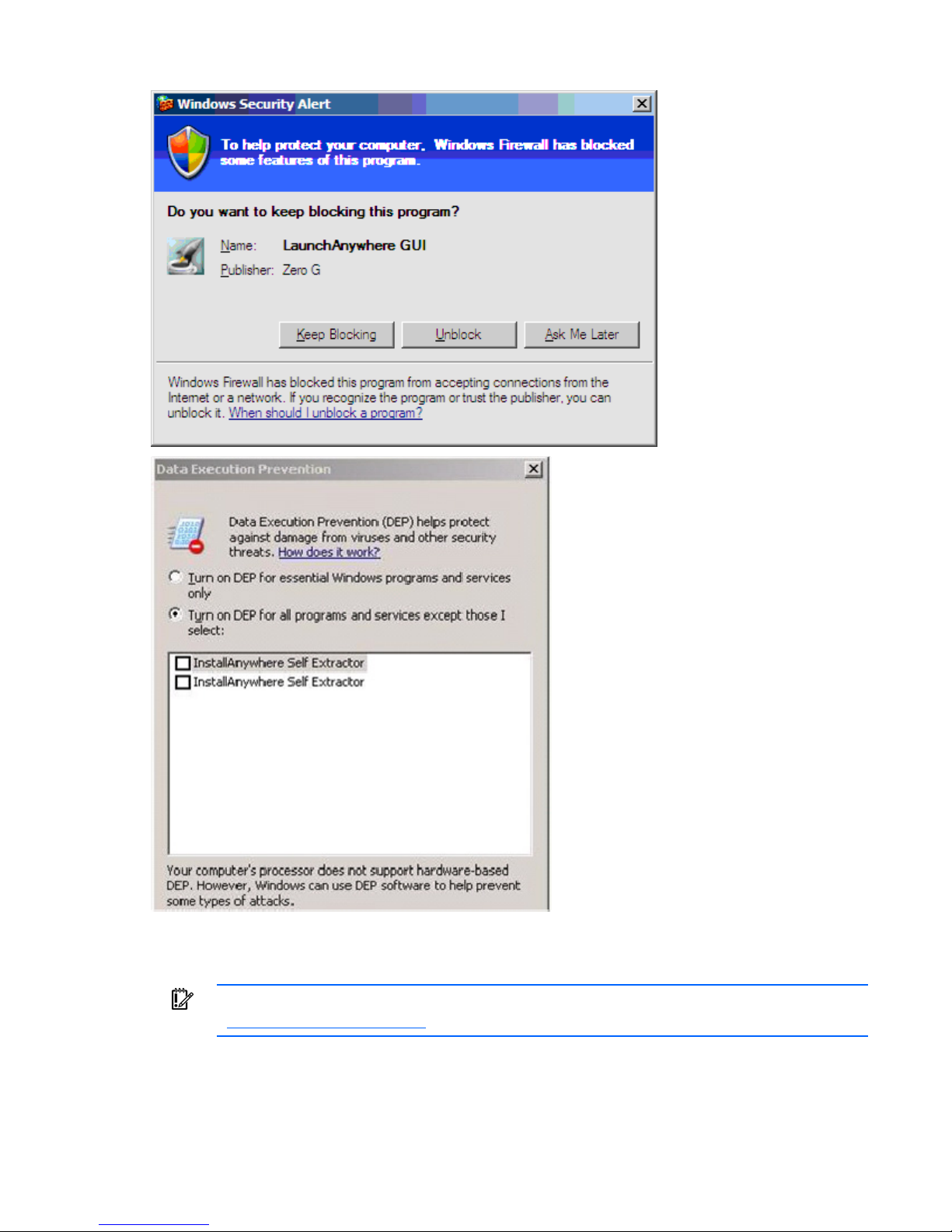
Windows XP SP1 or newer
To add a console switch without a preconfigured IP address and when the client software application is
not listed in the Windows® XP Firewall Exceptions List, the program must be added to the list of
Windows® XP Firewall Exceptions, and its scope must be set to the whole Internet.
NOTE: When installing the HP IP Console Viewer on a Windows Server™ 2003 server, if you
do not get a security dialog box and the installation program stops, you might need to restart
the server to get the security dialog.
NOTE: At the program startup, if you select Unblock, unblock is the default setting.
Installation 14
Page 15
Installing the HP IP Console Viewer
IMPORTANT: To ensure that you have the latest software, see the HP website
To install the HP IP Console Viewer on Windows® operating systems:
(http://www.hp.com/go/kvm
).
Installation 15
Page 16

1.
Insert the HP IP Console Viewer CD in to the CD-ROM drive. If AutoPlay is supported and enabled,
the setup program starts automatically.
-orIf your system does not support AutoPlay, set the default drive to the CD-ROM drive letter, and
execute the following command to start the install program:
<CD-ROM drive>:\WIN32\SETUP.EXE
2. Follow the on-screen instructions.
To install the HP IP Console Viewer on Linux operating systems:
1. Insert the HP IP Console Switch Viewer CD into your CD-ROM drive.
o If you are using Red Hat and SUSE Linux, the CD mounts automatically. Proceed to step 2.
o If the CD does not mount automatically, issue the mount command manually. The following is an
example of a typical mount command:
mount -t iso9660 device_file mount_point
Where device_file is the system-dependant device file associated with the CD and
mount_point is the directory that is used to access the contents of the CD after it is mounted.
Typical values include /mnt/cdrom or /media/cdrom.
2. Open a command window and navigate to the CD mount point. For example, cd/mnt/cdrom.
3. Enter the following command to start the installation, sh ./linux/setup.bin.
4. Follow the on-screen instructions.
Launching the HP IP Console Viewer
• To launch the HP IP Console Viewer on all Windows® operating systems, select Start>Programs>HP
IP Console Viewer.
-orFrom the desktop, double-click HP IP Console Viewer. The HP IP Console Viewer launches.
• To launch the HP IP Console Viewer on Linux operating systems:
If the product was installed in the default install directory (/usr/lib/IPViewer), then execute the
following command from a shell:
./IPViewer
-orIf the product was installed in a directory other than the default, then execute the following command
from a shell:
<path>/IPViewer
-orFrom the desktop, double-click HP IP Console Viewer. The HP IP Console Viewer launches.
Configuring the HP IP Console Viewer
IMPORTANT: To ensure that you have the latest software, see the HP website
(http://www.hp.com/go/kvm
).
Installation 16
Page 17

1.
Install the HP IP Console Viewer on each HP IP Console Viewer client.
2. From one of the HP IP Console Viewer clients, launch the HP IP Console Viewer.
3. Click New Console Switch to add the new console switch to the HP IP Console Viewer database. The
New Console Switch wizard appears.
4. If you previously configured the IP address, select Yes, the product already has an IP address. You
are prompted to provide the IP address of the console switch and complete the wizard.
-orIf you did not configure the IP address, select No, the product does not have an IP address. You are
prompted to assign an IP address, network mask, and gateway. The HP IP Console Viewer finds the
console switch and all interface adapters, or ports (for serial console switches), attached to it. These
names appear in the HP IP Console Viewer main window.
5. (Optional) Add additional console switches.
6. Set properties and group servers as desired into Sites or Folders through the main window.
7. Configure the console switch for access by clicking Manage Console Switch.
When prompted for login credentials, login using the Override Administrator User name (Admin).
The password is not set on new console switches. Remember to set the Override Admin Password
and keep it secure.
If local authentication is to be used select the User category and configure user names. For
information on adding internal users, see "Configuring user accounts (on page 44)" or "Configuring
user accounts for serial console switches (on page 113)."
If LDAP is to be used for authentication and authorization the console switch must be configured to
access the directory server. For information on configuring LDAP Authentication, see "Using directory
services integration (on page 201)."
Serial console switches can be configured for internal authentication, LDAP authentication, and also
RADIUS authentication. For more information, see "Configuring authentication parameters for serial
console switches (on page 104)."
8. After one HP IP Console Viewer client is configured, select File>Database>Save to save a copy of the
database with all the settings, and then share the file so that it can be loaded.
9. From the second HP IP Console Viewer client, select File>Database>Load, and browse to find the file
you saved.
10. If interface adapters are added, moved, deleted, or renamed after you loaded this file,
resynchronize your local database with the console switch by clicking Manage Console Switch,
selecting Settings>Servers, and clicking Resync.
11. To access a server attached to your console switch, select the desired server in the main window,
and click Launch KVM Session to launch a server session.
-orTo access a server attached to your serial console switch, select the desired server in the main
window, and click Launch Serial Session to launch a server session.
If SSH is enabled on the serial console switch to which the selected server is connected, then HP IP
Console Viewer automatically launches a secure session using SSH2. If SSH is not enabled, then a
plaintext Telnet session launches. If both SSH and plaintext sessions are enabled, then you are
prompted to select between launching an SSH or plaintext session, and are given the option to save
your preference for future sessions launched during this HP IP Console Viewer session. To clear your
preference select the Tools>Clear Login Credentials menu option.
Installation 17
Page 18

12.
Adjust the resolution by selecting View>Auto Scale, and click Maximize. Select Tools>Automatic
Video Adjust for the server video in the Video Session Viewer.
13. After setting the mouse properties, click mouse synchronization in the HP IP Console Viewer menu
bar.
Installation 18
Page 19

Navigating the HP IP Console Viewer
HP IP Console Viewer components overview
The HP IP Console Viewer consists of several components: the main window, the Manage Console Switch
window, the Video Session Viewer component, and Serial Session Viewer component. After you launch
the HP IP Console Viewer, the main window appears. The main window enables you to view, access,
manage, and create custom groupings for all the supported units in the data center.
When you select a server, you can click Launch KVM Session in the main window to launch the Video
Session Viewer. This component enables you to control the keyboard, monitor, and mouse functions of
individual servers. If the target device has a connection to a serial console switch, click the Launch Serial
Session icon to establish a telnet or SSH session to the target.
When you select a console switch, you can click Manage Console Switch in the main window to launch
the Manage Console Switch window. This window enables you to configure and control the console
switch.
Viewing the main window
The main window is divided into several different views. These views change based on the type of servers
selected or the task you want to complete. Click one of the views to see your system organized by
categories, such as console switches, servers, sites, or folders. The default display for the main window
can be configured by the user. By default, each time you launch the main window, it reads the local
database to determine which view to display.
Navigating the HP IP Console Viewer 19
Page 20
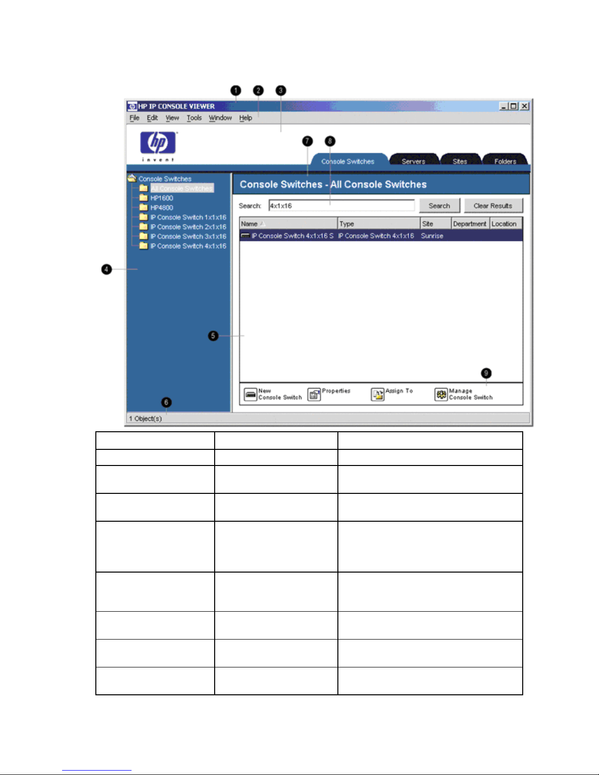
Main window features
Position Feature Function
1 Title bar Provides the title of the HP IP Console Viewer
2 Menu bar Contains six menus (File, Edit, View, Tools,
Window, and Help)
3 View Selector tabs Contains four tabs (Console Switches, Servers,
Sites, and Folders)
4 Group view Contains a tree view representing the groups
that are selected from the tab view (The group
view also controls what appears in the
selected view.)
5 List view Displays a list in the currently selected group
view or the results of a search executed from
the search bar
6 Status bar Displays the number of items shown in the list
view
7 Selected view Displays the search bar, list view, and task
window
8 Search bar Enables you to filter the list view displayed in
the selected view, based on the text entered
Navigating the HP IP Console Viewer 20
Page 21

Position Feature Function
9 Task window Contains buttons representing tasks that can
be executed (Some buttons are dynamic,
based on the type of items selected in the list
view, and other buttons are fixed and always
present.)
Auto searching for a server in the list view
1. Click Servers, and click any item in the List view.
2. Begin entering the first few characters of a server name. The highlight moves to the first server name
beginning with those characters.
To reset the search so you can find another server, pause for a few seconds, and enter the first few
characters of the next server.
Searching for a server in the local database
1. Click Servers.
2. Insert your cursor in the Search text box, and enter the search information.
3. Click Search.
4. Review the results of your search.
-orClick Clear Results to display the entire list again.
Navigating the HP IP Console Viewer 21
Page 22

Adding and discovering console switches
Adding console switches
Before a console switch can be accessed through the HP IP Console Viewer, you must add it to the HP IP
Console Viewer database. After the console switch has been manually added or discovered, it appears in
the list view.
If an IP address has already been assigned to the console switch, the HP IP Console Viewer automatically
discovers it by searching for an exact IP address or an address range. If an IP address has not yet been
assigned, you must manually add the console switch. If you are installing multiple console switches, HP
recommends using the Discover Wizard. If you are installing a single console switch, HP recommends
using the New Console Switch Wizard.
NOTE: For KVM console switches, HP recommends that you assign names to the target servers
in the console switch OSD before adding them to the HP IP Console Viewer. For serial console
switches, the server name should be configured on the associated serial console switch port
using the CLI. For more information, refer to the documentation included with the serial console
switch.
Adding a console switch without an assigned IP address
1. Select File>New>Console Switch, or click New Console Switch.
Adding and discovering console switches 22
Page 23
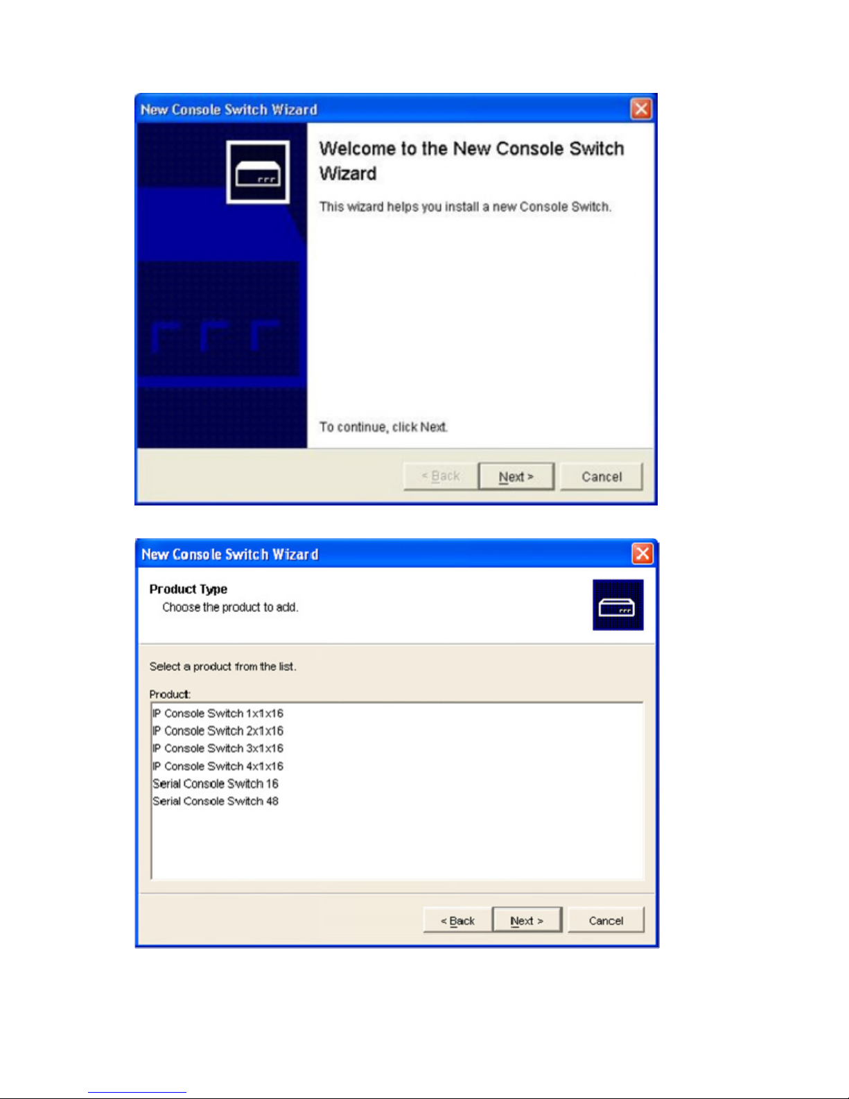
The New Console Switch Wizard appears.
2. Click Next. The Product Type window appears.
Adding and discovering console switches 23
Page 24
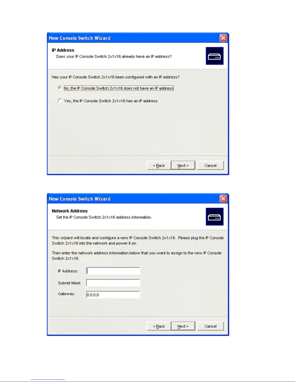
3.
Select a product from the product list. The IP Address window appears.
4. Indicate that the HP IP Console Switch does not have an IP address assigned by selecting No, and
click Next. The Network Address window appears.
Adding and discovering console switches 24
Page 25
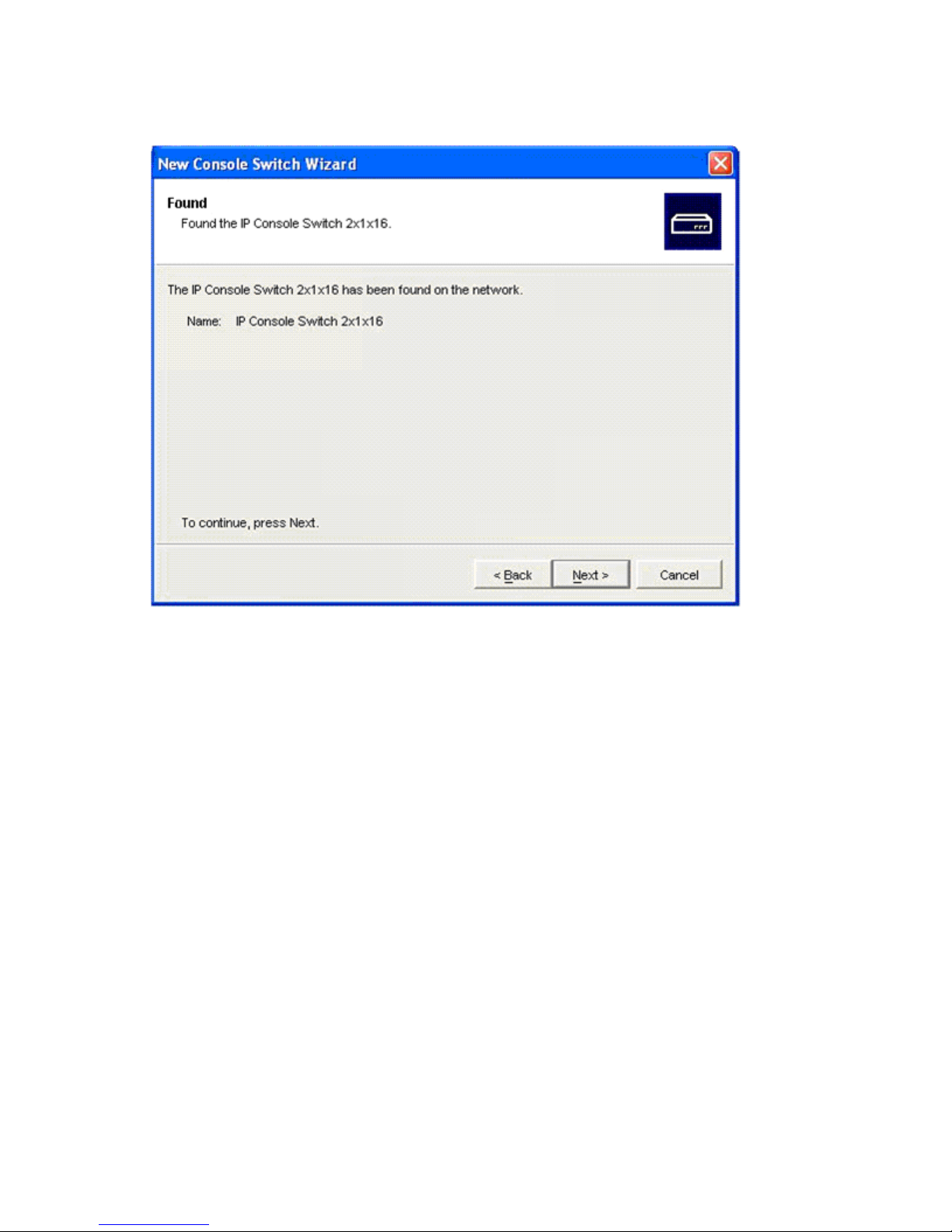
5.
Enter the IP address, subnet mask, and gateway for the console switch, and click Next. The HP IP
Console Viewer searches for the console switch and interface adapter IDs and server names
associated with the particular console switch. The Found window appears.
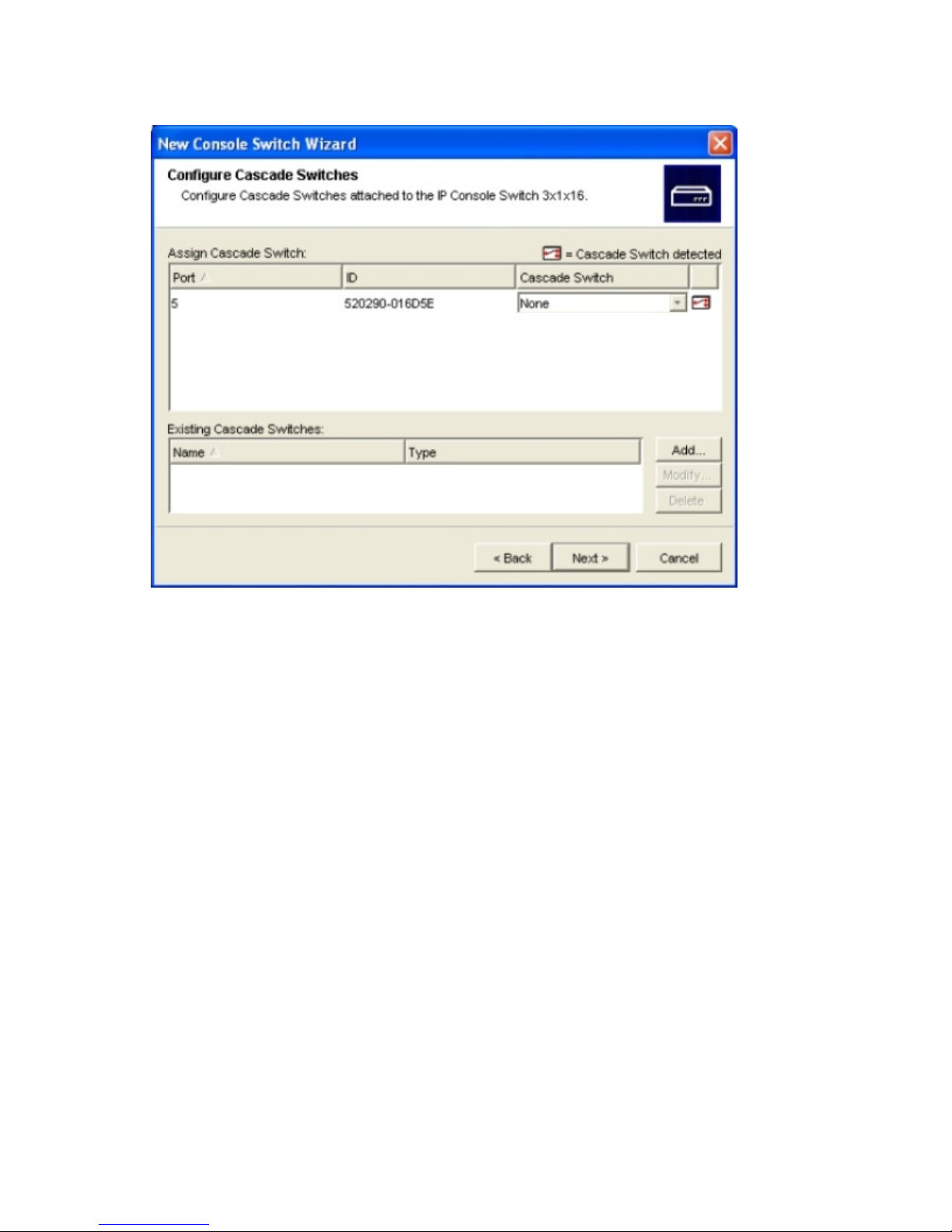
6. Click Next. If a cascade legacy analog console switch attached to an interface adapter is detected,
then the Enter Cascade Switch Information window appears.
a. The Assign Cascade Switch dialog box displays a list of all the interface adapters attached to a
cascade switch. Associate the appropriate console switch from the dropdown list for each
interface adapter that has a console switch attached.
b. The Existing Cascade Switches dialog box contains a list of all the current console switches
defined in the database. Click Add, Modify, or Delete to alter the list.
The HP IP Console Viewer searches only for the number of servers designated by the console
switch type (user definable).
After a cascade switch has been added to an Existing Cascade Switches list, you can modify or
delete the cascade switch displayed by selecting the cascade switch and clicking Modify or
Delete.
-or-
Adding and discovering console switches 25
Page 26
If no cascade switches attached to any interface adapters were detected, then the Completing
Wizard window appears. Click Finish to exit and return to the main window.
7. Click Next. The Completing the New Console Switch Wizard window appears.
8. Click Finish to exit and return to the main window. The console switch displays in the list view.
Adding a console switch with an assigned IP address
1. Select File>New>Console Switch, or click New Console Switch. The New Console Switch Wizard
window appears.
2. Click Next. The Product Type window appears.
Adding and discovering console switches 26
Page 27
3.
Select a product from the product list, and click Next. The IP Address window appears.
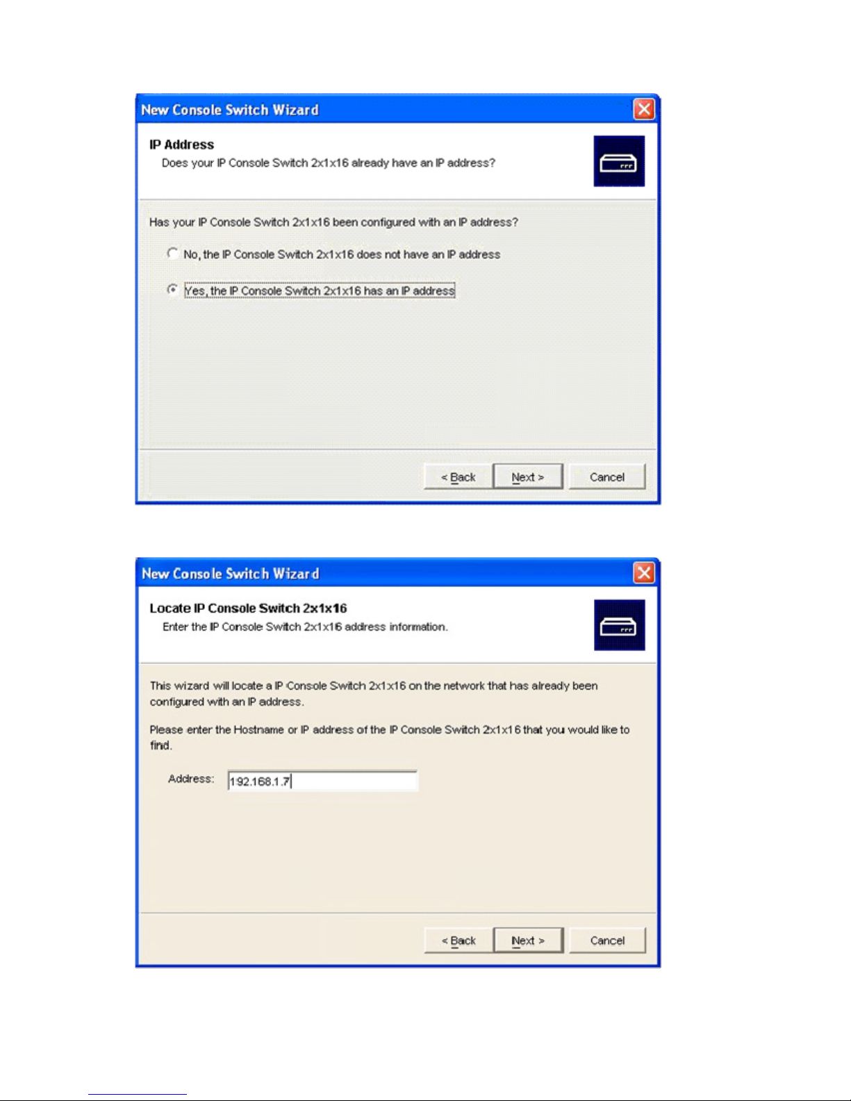
4. Indicate that the HP IP Console Switch has an IP address assigned to it by selecting Yes, and click
Next. The Locate IP Console Switch window appears.
Adding and discovering console switches 27
Page 28

5.
Enter the HP IP Console Switch IP address or DNS name, and click Next. The IP Console Viewer
searches for the console switch and all interface adapter IDs and server names associated with the
particular console switch. The Found window appears.
6. Click Next. If a cascade legacy analog console switch attached to at least one interface adapter is
detected, then the Enter Cascade Information window appears.
a. The Assign Cascade Switch dialog box displays a list of all the interface adapters attached to a
cascade switch. Associate the appropriate console switch from the dropdown list for each
interface adapter that has a console switch attached.
b. The Existing Cascade Switches dialog box contains a list of all the current console switches
defined in the database. Click Add, Modify, or Delete to alter the list.
The IP Console Viewer searches only for the number of servers designated by the console switch
type (user definable).
After a cascade switch has been added to an Existing Cascade Switches list, you can modify or
delete the cascade switch displayed by selecting the cascade switch and clicking Modify or
Delete.
-orIf no cascade switches attached to any interface adapters were detected, then the Completing
Wizard window appears. Click Finish to exit and return to the main window.
7. Click Next. The Completing the New Console Switch Wizard window appears.
8. Click Finish to exit and return to the main window. The console switch appears in the list view.
Adding and discovering console switches 28
Page 29
Discovering one or more console switches with the
Discover Wizard
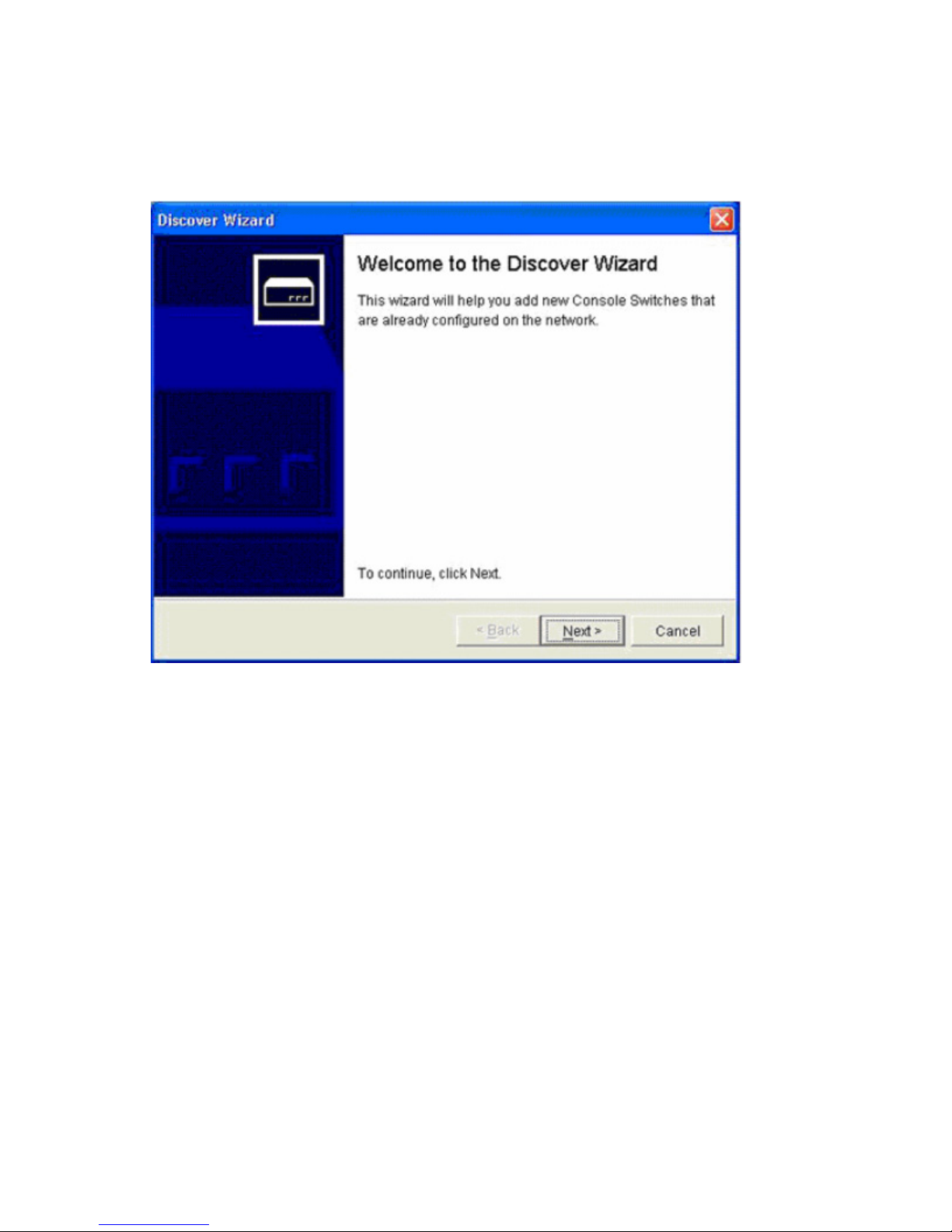
1. Select Tools>Discover. The Discover Wizard window appears.
Adding and discovering console switches 29
Page 30
2.
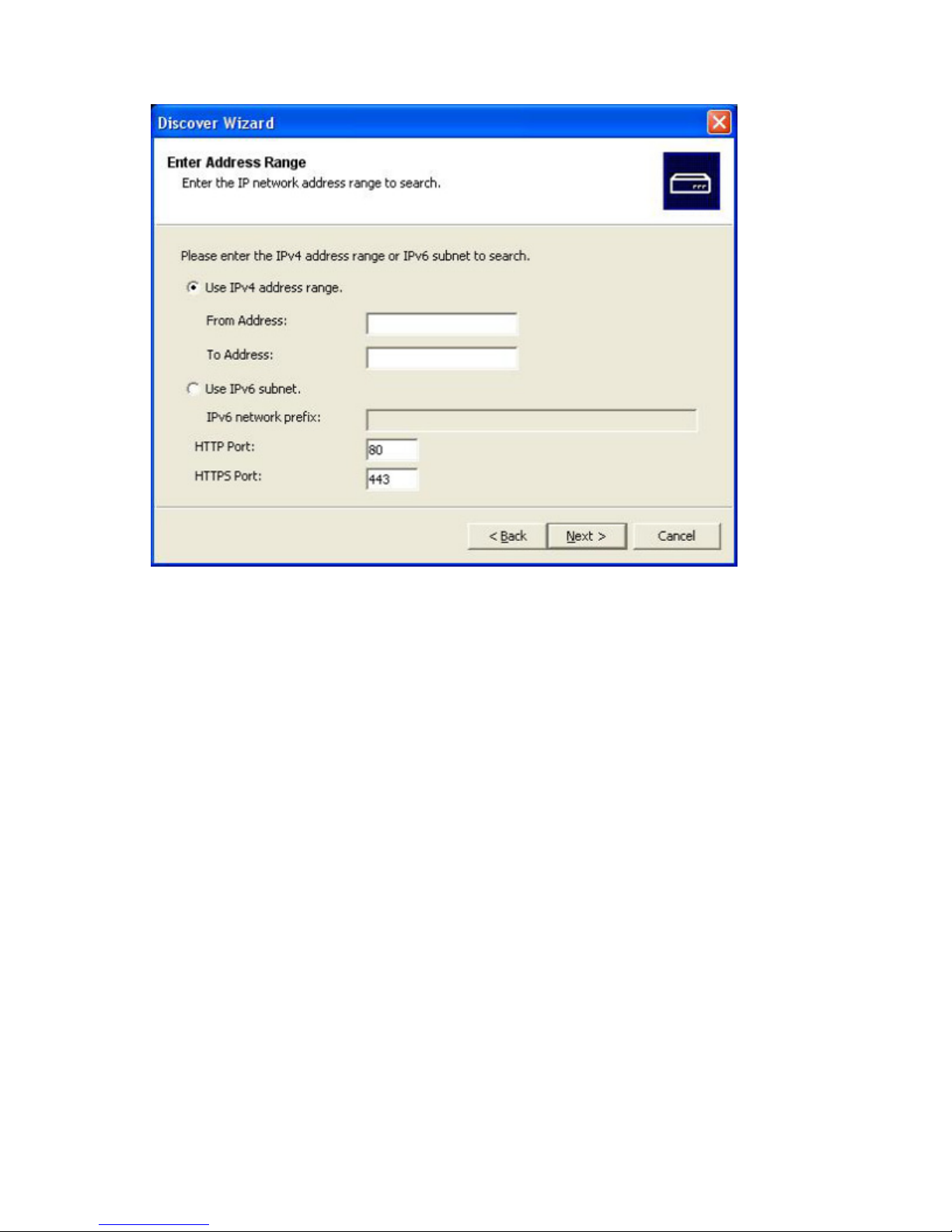
Click Next. The Enter Address Range window appears.
3. Enter the IP address range or IP subnet by choosing one of the following options:
o Select Use IPv4 address range,and then enter a valid range of network IPv4 addresses to search
on the network in the From Address and the To Address fields. Use the IP address dot notation:
xxx.xxx.xxx.xxx.
o Select Use IPv6 subnet,and then enter a valid IPv6 subnet prefix in Address/Prefix-Length notation
to search an IPv6 subnet.
Adding and discovering console switches 30
Page 31

4.
Click Next. The Searching Network window appears. Progress text indicates how many addresses
have been probed from the total number specified by the range and the number of IP console
switches found.
o If one or more new console switches are discovered, the Select Console Switches window
appears. From this window, you can select the console switches to add to the local database.
Continue to step 6.
Adding and discovering console switches 31
Page 32

o
If no new console switches are found or if you pressed Stop during the add process, the Discover
Wizard was unsuccessful window appears. Click Finish to exit. You must manually add the
console switch. For more information, see "Adding a console switch without an assigned IP
address (on page 22)."
NOTE: If you are using Windows XP SP2 and are trying to discover a broad range of IP
addresses and the device you are trying to discover does not display, limit the number of TCP
5. Select one or more console switches to add from the Console Switches Found box and then click the
threads to ten.
> button to move the selection to the Console Switches to add box. Repeat these steps for all the
console switches that you want to add.
6. Click Next. The Adding Console Switches window appears. A progress bar appears while new
console switches are added to the list.
When all of the selected consoles have been added to the local database, the Completing the
Discover Wizard window appears. Click Finish to exit and return to the main window. The new
console switches appear in the list view.
If any console switches were not added to the local database for any reason, including if you
pressed Stop during the add process, the Discover Wizard Not All Console Switches Added page
appears. This page lists all of the console switches that you selected and the status for each. The
status is indicated if a console switch was added to the local database and if not, why the process
failed. Click Done when you are finished reviewing the list.
NOTE: If a console switch already exists in the local database with the same IP address as a
discovered console switch, then the discovered console switch is ignored and is not displayed
on the next Discover Wizard window.
Adding and discovering console switches 32
Page 33

Managing multiple connections
A server that has connections to more than one console switch managed by the HP IP Console Viewer
usually appears as two different servers in the main window when the console switches are initially
discovered. For example, a server can have a serial console port connected to a serial console switch, in
addition to being connected to a kvm console switch.
You can configure such a server to appear only once, and the main window provides the valid
connection methods for accessing the server (for example, the Launch KVM Session and Launch Serial
Session task buttons). To configure a server to appear only once, the serial console switch port name and
the KVM console switch interface adapter must be set to the same name. You can rename the interface
adapter, or serial port, through the Servers category in the Manage Console Switch window.
To rename an interface adapter through the HP IP Console Viewer:
1. Access the console switch ("Accessing console switches" on page 36).
2. Select Servers.
3. Highlight the server in the Servers column that you want to modify. You can modify only one server
at a time.
4. Click Modify. The Modify dialog box appears with the current name of the server as stored in both
the console switch and the client database (not necessarily the same).
5. Enter the new name of the server in the New Name: field.
6. Click OK to change the server name.
7. Repeat steps 1 through 5 for every server name that you want to change.
8. Click Apply to save any changes. This process dynamically updates the HP IP Console Viewer
database, the console switch and the interface adapter simultaneously.
To rename the serial ports on the serial console switch through the HP IP Console Viewer:
1. Access the serial console switch ("Accessing console switches" on page 36).
2. Select Servers.
3. Select the server in the Servers column that you want to modify. You can modify only one server at a
time.
4. Click Modify. The Modify dialog box appears with the current name of the server as stored in both
the console switch and the client database (not necessarily the same).
5. Enter the new name of the server in the New Name: field.
6. Click OK to change the server name.
7. Repeat steps 1 through 5 for every server name that you want to change.
8. Click Apply to save any changes. This process dynamically updates the HP IP Console Viewer
database, the console switch and the interface adapter simultaneously.
To rename the server locally:
1. Using the serial console switch CLI, issue a Port Set command with the Name parameter. For
example, if you want the server connection to the serial console switch to have the same name as its
KVM console switch connection, change the name using the serial console switch CLI. For more
information on CLI commands, see the documentation included with the serial console server.
2. Using the KVM console switch OSD, configure the server name with the Names dialog box. For
more information on the OSD, see the user guide included with your KVM console switch.
Adding and discovering console switches 33
Page 34

3.
Resynchronize the server list in the appropriate Manage Console Switch window. For more
information, see "Resynchronizing the server listing for console switches (on page 61)" or
"Resynchronizing the server listing for serial console switches (on page 138)."
For example, if you changed the server name on the serial console switch, resynchronize the server
list in the Manage Serial Console Switch window.
Server naming
The HP IP Console Viewer requires that each KVM console switch, serial console switch, and server have
a unique name. The HP IP Console Viewer uses the following procedure to generate a unique name for a
server whose current name conflicts with another name in the database.
During background operations (such as an automated operation that adds or modifies a name or
connection), if a name conflict occurs, the conflicting name is automatically made unique. This is done by
appending a tilde (~) followed by an optional set of digits. The digits are added in cases where adding
the tilde alone does not make the name unique. The digits start with a value of one and are incremented
until a unique name is created.
During normal operations, if you specify a non-unique name, a message appears informing you that the
server name is already in the database and you are prompted to merge server records. This option is
useful when a target server can be managed by both the KVM session and a serial interface. For more
information, see "Modifying server names (on page 60)" or "Modifying server names for serial console
switches (on page 137)."
Server name displays
When a KVM console switch is added, the server names retrieved from the KVM console switch or serial
console switch are stored in the HP IP Console Viewer database. The operator can then rename a server
in the main window, and the new name is stored in the database and used in various HP IP Console
Viewer component screens. This new server name is not communicated to the KVM console switch or
serial console switch.
Because HP IP Console Viewer is a decentralized management system, the name assigned to a server on
the console switch or serial console switch can be changed at any time without updating the HP IP
Console Viewer database. This feature enables each operator to customize a particular HP IP Console
Viewer view of the list of servers being managed.
Because there can be more than one name associated with a single server, one on the KVM console
switch or serial console switch, and one in the HP IP Console Viewer, the HP IP Console Viewer uses the
following rules to determine which name appears:
• The main window shows only the servers listed in its database, with the name specified in the
database. In other words, the main window does not talk to the console switch or serial console
switch to obtain server information.
• The Manage Console Switch window displays information retrieved from the console switch, except
where noted.
• The Resync Wizard (which is used to resynchronize the server list in the Manage Console Switch
window) overwrites locally defined server names only if the console switch server name has been
changed from the server value in the Manage Console Switch window (its default value). For
example, in KVM console switches, the default server name values are the EID of the interface
adapter to which they are attached. In serial console switches, the default server name values are
Adding and discovering console switches 34
Page 35

comprised of the console switch's MAC Address and the port number of the port to which the server
is attached. Non-default server names that are read from the console switch during a
resynchronization are allowed to override the locally defined names.
Sorting displays
In certain displays, an HP IP Console Viewer component displays a list of items with columns of
information about each item. If a column header contains an arrow, you can sort the display by that
column in ascending or descending order.
To sort a display by a column header, click the column header. The items in the list will be sorted
according to that column. An upward-pointing arrow indicates the list is sorted by that column header in
ascending order. A downward-pointing arrow indicates the list is sorted by that column header in
descending order.
Managing cached credentials
To access KVM console switches, serial console switches, and servers, you must first enter a user name
and password (credentials). The HP IP Console Viewer uses credential caching, which captures
credentials upon first use and automates the authentication of subsequent unit connections.
After successfully authenticating, cached credentials are used whenever you access other units during that
HP IP Console Viewer session, and the user name and password prompt does not appear unless
authentication with the cached credentials fails.
Clearing login credentials
You can clear cached credentials at any time.
NOTE: Clearing login credentials also clears your preference for SSH versus plaintext serial
To clear login credentials:
1. Select Tools>Clear Login Credentials. A message appears.
2. Click OK to exit.
sessions, if previously saved.
Adding and discovering console switches 35
Page 36

Accessing console switches
Accessing console switches overview
When you click the Console Switches icon, you see a list of the console switches currently defined in the
local database.
To access a console switch, first log in with a valid password and user name. After you log into the
console switch, the HP IP Console Viewer caches the user name and password into memory for the
duration of the HP IP Console Viewer session. All HP IP Console Switch Viewer communications to the
console switch use an SMP connection.
NOTE: You can clear the login credentials. For information on clearing the login credentials,
see "Clearing login credentials (on page 35)."
To access a console switch:
1. Click Console Switches to display the console switches in the selected view.
2. Double-click the desired console switch. A login dialog box appears.
-orSelect the console switch, and click Manage Console Switch. A login dialog box appears.
-orRight-click the console switch, and select Manage Console Switch from the resulting list. A login
dialog box appears.
-orClick Console Switches, and press Enter. A login dialog box appears.
3. Enter a valid user name and password. If a new user name and password have not been created,
the Override Admin. account can be used. The default user name for this account is Admin (casesensitive), and the default password field is blank.
IMPORTANT: If you have previously logged in to the console switch during the same HP IP
Console Viewer session, the login dialog does not display unless authentication or
4. Click OK. The Manage Console Switch window appears. For information on managing console
authorization fails or you clear the login credentials.
switches, see "Managing KVM console switches (on page 37) or "Managing serial console switches
(on page 99)."
-orClick Cancel to exit without logging in.
Accessing console switches 36
Page 37

Managing KVM console switches
Manage Console Switch window overview for KVM
console switches
After you have installed a new KVM console switch, you can view and configure unit parameters, view
and control currently active video sessions, and execute a variety of control functions, such as rebooting
and upgrading your KVM console switch.
The Manage Console Switch window consists of three tabs:
• Settings tab for KVM console switches ("Viewing and configuring parameters through the Settings
tab" on page 37)
• Status tab for KVM console switches ("Viewing the Status tab" on page 70)
• Tools tab for KVM console switches ("Using the Tools tab" on page 71)
Some operations that you initiate through the Manage Console Switch window can cause a dialog box to
appear, indicating that a reboot is required for the change to take effect. In such cases, you can choose
to reboot immediately or wait to reboot later.
NOTE: References to the local user refer to an OSD user connected to the console switch.
For more information about the KVM console switch and its operations, see the documentation included
with the KVM console switch.
Viewing and configuring parameters through the
Settings tab
The Settings tab enables you to display an expandable list of categories covering a wide range of
parameters for the console switch. When a category is selected, the parameters associated with that
category are read from the console switch, the database, or both. You can modify those parameters and
Configuring global parameters
send changes securely back to the console switch through the SMP.
The Global category enables you to view the Product Type, Serial Number (EID), and the Language
settings for the console switch.
Managing KVM console switches 37
Page 38

The Serial Number (EID) field contains information for the HP IP Console Switch hardware and the EID
attached to that console switch.
Configuring network parameters
The Network subcategory enables you to view the network settings of a console switch, including the
Name (read-only), IP Address, Subnet Mask, Gateway, MAC Address (read-only), LAN Speed, DNS
Servers, and Bootp settings. You can change the console switch name in the SNMP category.
The DNS servers can be used to find domain controllers during LDAP authentication and authorization
operations, but HP recommends using IP addresses.
Managing KVM console switches 38
Page 39

The DNS Server fields appear only if LDAP Authentication is licensed on the console switch.
To change network parameters:
1. Select Network.
2. Select Enabled if a BOOTP server is to be used to obtain the network configuration. The remaining
fields on this panel are disabled.
-orSelect Disabled if a static network configuration is used to obtain the network configuration.
a. In the IP Address field, enter the address in IP dot notation of the console switch. The value
cannot be a loopback address or all zeros.
b. In the Subnet Mask field, enter the subnet mask in IP address dot notation of the console switch.
The value cannot be a loopback address or all zeros.
c. In the Gateway field, enter the gateway address in IP address dot notation of the console switch.
The value cannot be a loopback address. If there is no gateway address, enter 0.0.0.0.
d. In the DNS Servers fields, enter the address in IP dot notation of up to three DNS servers.
3. Click Apply to save any changes without exiting.
-or-
Managing KVM console switches 39
Page 40

Click OK to save any changes and exit.
Configuring session parameters
The Sessions subcategory enables you to specify the active Video Session Timeout, which configures the
console switch to close an inactive video session after a specified number of minutes.
NOTE: If a video session is associated with a reserved Virtual Media session, then the video
This subcategory also enables you to configure the preemption warning settings. Enabling the Video
session preemption timeout option enables you to specify the time (5 to 120 seconds) for which a
preemption warning message appears before a video session is preempted. If this option is not enabled,
preemption occurs without warning.
You can also set the SSL encryption levels to use for the encryption of keyboard and mouse data of all
video sessions to the console switch. You can also enable video encryption.
Video encryption is optional, but at least one Keyboard/Mouse encryption level must be selected.
The Sessions subcategory can also be used to enable Connection Sharing options. In the Connection
Sharing area, select sharing options as needed.
• If you select Enable Share Mode, users can share KVM sessions for the same server.
• If you select Automatic Sharing, secondary users can share KVM sessions without first requesting
session is not subject to the video session timeout.
permission from the primary user.
• If you select Exclusive Connections, primary users can designate a KVM session as exclusive
(exclusive sessions cannot be shared).
• If you select Stealth Connections, administrators can monitor a server and remain undetected.
You can also specify in the Input Control Timeout field the number of seconds the console switch will wait
for activity before transferring keyboard and mouse control from the primary user to the secondary user.
NOTE: The highest encryption level will be used, based on the following order (highest to
lowest):
• 128-bit encryption
• 3DES
• DES
Managing KVM console switches 40
Page 41

For more information on connection sharing, see "Video session types (on page 79)."
Managing KVM console switches 41
Page 42

Configuring Virtual Media parameters
The Virtual Media subcategory enables you to specify the settings for Virtual Media sessions.
Parameter Function
Lock to KVM Session When selected, a Virtual Media session is not allowed to remain after the Video
Session Viewer that launched it closes. If not selected, the virtual media session is
allowed to remain when the associated video session is closed. This setting is
enabled by default.
Allow Reserved
Sessions
Read-Only Access Prevents write access to the Virtual Media devices that allow it. CD-ROMs and other
Enables Virtual Media sessions to be reserved. The user only allowed to establish a
KVM session to a reserved virtual media session is the owner of the Virtual Media
session. This setting affects the showing of the reserved setting in the Virtual Media.
If this feature is enabled, KVM sharing is not allowed while there is a reserved
Virtual Media session. If you select Allow Reserved Sessions, then the owner of the
Virtual Media session can choose to prevent other users from establishing a KVM
session to the same server. Also when the Virtual Media session is reserved, the
corresponding KVM session is not subject to inactivity timeouts and cannot be
preempted. This setting is disabled by default.
media that do not allow write access are not affected by this setting. This setting is
enabled by default.
Managing KVM console switches 42
Page 43

Parameter Function
Encryption level This control can be used to specify the encryption method to use for all Virtual Media
sessions. This information is used when new client connections are requested. At that
point, the console switch will attempt to negotiate for the highest enabled encryption
mechanism level. This setting is disabled by default.
To configure these settings:
1. Select Virtual Media.
2. Enable or disable the checkboxes in the Session Control area.
o If you clear the Lock to KVM Session option, your Virtual Media sessions can remain after the
Video Session Viewer that launches the session closes.
o If you select Allow Reserved Sessions, only the owner of the Virtual Media session can establish a
KVM session to a reserved Virtual Media session.
o If you select Read-Only Access, write access to Virtual Media sessions is prevented.
3. Select zero or more levels of encryption to encode Virtual Media data sent to the console switch in
the Encryption Level area. The highest level enabled will be used.
4. Click Apply to save any changes without exiting.
-orClick OK to save any changes and exit.
-orClick Cancel to exit without saving any changes.
Configuring authentication parameters
The Authentication subcategory enables you to select the type of authentication method to be used.
IMPORTANT: Before implementing LDAP functionality, see "HP IP Console Switch directory
services integration setup tutorial (on page 277)" for a better understanding of how LDAP
The three types of authentication are:
• Local Authentication (with local access control)
• LDAP Authentication Only (with local ACL)
works.
Provides secure managed switch based authentication, data transfers, and user name and password
storage. With two levels of access control, Console Switch Administrator and User, you can set
target server-specific access rights and inter-operate with existing firewalls, VPNs, and NAT-based
networks. This is the default setting and has the same functionality as in the previous software
release.
Provides a secure managed directory-based authentication for passwords and user names and a
local switch-based authorization for ACLs. ACLs are maintained and stored in each individual
console switch. Passwords are only in the directory server. For more information on LDAP, see
"Using directory services integration (on page 201)."
• LDAP Authentication and Access Control
Managing KVM console switches 43
Page 44

Provides a secure managed directory-based authentication for user names and passwords, as well
as access control. User rights and user accounts are stored in the directory. For more information on
LDAP Access Control, see "Using directory services integration (on page 201)."
Configuring user accounts
The Users category enables you to configure user accounts. There are two types of user accounts: internal
and external. Internal accounts, such as Local Authentication accounts, reside within the console switch,
while external accounts, such as LDAP Authentication and Access Control accounts, are stored in the
directory.
When you select the Users category for the first time, the Manage Console Switch function retrieves and
displays user information and current access levels based on the type of authentication you have selected.
• When Local Authentication or LDAP Authentication Only modes are enabled, the Manage Console
Switch retrieves and displays a list of user names and current access levels from the console switch.
Through the Users category, when Local Authentication or LDAP Authentication Only modes are
enabled, you can:
o Add, modify, or delete users in this listing (user names must match the user in the Directory if
LDAP is used for authentication)
Managing KVM console switches 44
Page 45

o
Assign access levels: Console Switch Administrator or User
o Assign individual server access rights to a user through the User Access Level function
o Enable the Security Lock-out feature that can lock out users if they try to enter an invalid password
five consecutive times (This feature enables you to configure the Security Lock-out settings, as well
as unlock any users.)
NOTE: The Security Lock-out feature applies only to Local authentication. When LDAP
authentication is used, the lockout functionality of the directory service is used.
• When LDAP Authentication and Access Control mode is enabled, the user names and access rights
are stored in and managed from the Active Directory.
A user can be assigned one of two access levels: Console Switch Administrator or User. The user access
level enables you to assign individual server access rights to a user. The table following indicates the
types of console switch operations that may be performed in each access level.
Operation Console Switch
Preemption All No
User
Administrator
Managing KVM console switches 45
Page 46

Operation Console Switch
Configure Global and
Network settings (security
mode, timeout, and SNMP)
Reboot Yes No
Upgrade Yes No
Administer user accounts Yes No
Configure port settings Yes No
Monitor server status Yes No
Server device access Yes Assigned by admin
Server resync Yes Yes
Adding or modifying a user
Adding or modifying a Local Authentication user
1. Select Users.
2. Select a user.
3. Click Add to add a new user. The Add User dialog box appears.
User
Administrator
Yes No
-orClick Modify to modify a current user. The Modify User dialog box appears.
IMPORTANT: Passwords must be between five and 16 characters in length, contain both
alphabetic and numeric characters, and contain both uppercase and lowercase alphabetic
characters.
IMPORTANT: User names must be between one and 16 characters. If you intend on using the
optional LDAP functionality in the future, be sure to follow the Microsoft® Active Directory user
account rules when creating a user name.
4. Enter the user name and password (user assigned), and verify the password by entering it again in
the Verify Password field.
.
NOTE: The Access Rights button is enabled only when Access Level=User is selected.
Managing KVM console switches 46
Page 47

NOTE: The password fields are disabled (grayed-out), when using LDAP Authentication Only
mode.
5. Select the appropriate access level for the user from the Access Level dropdown list. If you select the
User option, the Access Rights button activates.
a. Click Access Rights to select individual servers for that user. The User access rights dialog box
appears.
b. From the left column, select one or more servers for which this user should have access rights.
Click Add.
c. From the right column, select one or more servers from which to remove the access rights of a
user. Click Remove.
d. Repeat steps b and c until the right column represents the appropriate server access for this user,
and click OK.
6. Click OK to save settings and return to the main window, or click Cancel to exit.
Adding or modifying an LDAP Authentication Only user
NOTE: For LDAP Authentication and Access Control users, add user accounts and passwords
in the directory.
1. Select Users.
2. Select a user.
IMPORTANT: The user name in the Users category must be the same as the display name in
the active directory.
3. Click Add to add a new user. The Add User dialog box appears.
-or-
Managing KVM console switches 47
Page 48

Click Modify to modify a current user. The Modify User dialog box appears.
4. Select the appropriate access level for the user from the Access Level dropdown list. If you select the
User option, the Access Rights button activates.
a. Click Access Rights to select individual servers for that user. The User access rights dialog box
appears.
b. From the left column, select one or more servers for which this user should have access rights.
Click Add.
c. From the right column, select one or more servers from which to remove a user's access rights.
Click Remove.
d. Repeat steps b and c until the right column represents the appropriate server access for this user,
and click OK.
5. Click OK to save the settings and return to the main window, or click Cancel to exit.
Setting user access rights
1. Click Access Rights to select individual servers for that user. The User access rights dropdown list
appears.
2. Select a server in the left column, and click Add.
3. Select a server in the right column, and click Remove.
4. Repeat steps 2 and 3 until the right column represents the appropriate server access for the assigned
user, and click OK.
Managing KVM console switches 48
Page 49

Deleting a user
1. Select Users.
2. Select a user.
3. Click Delete. The Confirm Deletion dialog box appears.
4. Click Yes to confirm the deletion, or click No to exit the window without deleting the user.
Locking and unlocking user accounts
If the console switch is configured for Local Authentication and a user enters an invalid password five
consecutive times, the Security Lock-out feature temporarily disables that account. If a user attempts to log
in again, an error message appears from the software client application. All local accounts, except the
Override Admin account are subject to this lock-out policy.
An administrator can specify the number of hours (1 to 99) that accounts are locked. When Enable Lockouts is not selected, the Security Lock-out feature is disabled, and no users can be locked out.
If an account becomes locked, it remains locked until the number of hours specified in the Duration field
has elapsed, the console switch is power cycled, or an administrator unlocks the local account using the
Unlock function on this panel.
NOTE: If your account is locked and you have LDAP Authentication and Access Control
enabled, your account must be unlocked through the Active Directory. Contact your active
directory administrator for further details.
Managing KVM console switches 49
Page 50

Unlocking an account
1. Select Users.
Managing KVM console switches 50
Page 51

2.
Click Unlock. The Lock icon next to the user name disappears.
3. Click OK or Apply. The user can log in.
-orClick Cancel to exit without saving.
Enabling or disabling a security lock-out
1. Select Users.
2. Select Enable Lock-outs. Enter the number of hours (1 to 99) in the lock-out period in the Duration
field.
-orClear Enable Lock-outs.
3. Click Apply, and then click OK.
NOTE: Disabling Security Lock-out has no effect on users who are already locked out.
Managing KVM console switches 51
Page 52

Specifying a security lock-out duration
1. Select Users.
2. Select Enable Lock-outs.
3. Enter the number of hours that a user is locked out (1 to 99) in the Duration field.
4. Click Apply, and then click OK.
Override Admin
Override Admin is the one account that can be used to get into the console switch from a network, even if
the local accounts are locked or do not exist or if LDAP is not working properly. The Override Admin
account is a permanent account that cannot be deleted. It has the same access right privileges as a
Console Switch Administrator. The ID and password should be closely held by authorities and should not
be used as Admin or User accounts on a day-to-day basis. The Override Admin account name and
password settings are accessible only to the Override Admin user. The Override Admin account
authenticates only locally to the console switch and the directory.
NOTE: For 1 x 1 x16 and 3 x 1 x16 IP console switches when upgrading from a firmware
version before 3.0.0, the upgrade procedure searches for an existing Console Switch Admin
account named "Admin" and migrates this user name and password to be the default Override
Admin account. If the user "Admin" is not found, then the default Override Admin user name
will be "Admin" and the default password will not be set (empty).
Managing KVM console switches 52
Page 53

Viewing interface adapter parameters
The Interface Adapters category displays a list of interface adapters attached to the HP IP Console Switch
and their statuses, as well as the port, interface adapter ID, type, and language. A green circle indicates
that the interface adapter is online. A yellow circle indicates that the interface adapter is being upgraded,
and a red X indicates that interface adapter is offline. To clear offline adapters, click Clear Offline, and
then click OK when prompted to confirm.
NOTE: The interface adapter Status, Port, ID, Type, and Language columns can be sorted by
selecting the column name.
NOTE: The Clear Offline button is only enabled if at least one interface adapter is offline.
Managing KVM console switches 53
Page 54

Setting interface adapter language parameters
The Language setting specifies the keyboard layout language to be reported by USB interface adapters to
the attached servers.
1. Select Interface Adapter.
2. Click Language.
3. Select the keyboard layout from the dropdown menu.
Managing KVM console switches 54
Page 55

4.
Click OK to select the keyboard layout.
-orClick Cancel to return without changing the language.
5. Click Apply to save any changes without exiting.
-orClick OK to save any changes and exit.
-orClick Cancel to exit without saving any changes.
All online interface adapters report in the new language.
Configuring SNMP parameters
SNMP is a protocol used to communicate management information between network management
applications and console switches. Other SNMP managers can communicate with your console switch by
accessing MIB-II and the public portion of the enterprise MIB. MIB-II is a standard MIB that many SNMP
servers support.
When you select the SNMP category for the first time, the Manage Console Switch window retrieves the
SNMP parameters from the console switch. The SNMP category enables you to enter system information
and community strings, designate the management stations that can manage the console switch, and
retrieve SNMP traps from the console switch. If you select Enable SNMP, the console switch responds to
SNMP requests over UDP port 161. Port 161 is the standard UDP port used to send and retrieve SNMP
messages.
NOTE: The Manage Console Switch window uses SNMP within a secure tunnel to manage
console switches. For this reason, UDP port 161 must be open on firewalls. You must expose
UDP port 161 to monitor console switches through third-party SNMP-based management
Up to four allowable managers can be defined, and all IP addresses are defined as blank by default. If
all four entries are left blank, all IP addresses are authorized to read and write to the console switch,
provided that they have the correct SNMP community strings. If any of the SNMP allowable manager
entries are not blank, then only the defined SNMP allowable managers have access.
software.
Managing KVM console switches 55
Page 56

The allowable managers setting does not affect whether the HP IP Console Viewer can view or manage
the console switch.
Configuring general SNMP parameters
1. Select SNMP.
2. Select Enable SNMP to configure the console switch to respond to SNMP requests over UDP port
161.
3. In the System section, enter the fully qualified domain name of the system in the Name field, a
description in the Description field, and a contact person in the Contact field.
IMPORTANT: If you are using LDAP or are planning to use LDAP in the future, the name in the
Name field must match the computer name that represents the console switch in the Active
4. Enter the community names in the Read, Write, and Trap fields. These specify the community strings
Directory.
that must be used in SNMP actions. The read and write strings apply only to SNMP over UDP port
161 and act as passwords that protect access to the console switch. The values can be up to 64
characters in length.
Managing KVM console switches 56
Page 57

5.
Add up to four SNMP management stations that are allowed to monitor the console switch, such as
HP Systems Insight Manager, or leave the field blank to allow any SNMP management station to
manage the console switch. For more information, see "Adding, modifying, and deleting allowable
managers (on page 57)."
6. Add up to four SNMP trap destinations to which this console switch sends traps and in the Trap
Destination field. For more information, see "Adding, modifying, and deleting trap destinations (on
page 57)."
7. Click OK to save the settings and close the window.
-orClick Apply to save the settings and remain in the open window.
-orClick Cancel to exit the window without saving.
Adding, modifying, and deleting allowable managers
In the Allowable Managers area, you can specify up to four SNMP management entities to monitor this
console switch or leave this area blank to allow any station to monitor the console switch. You can also
modify or delete an existing allowable manager.
To add an Allowable Manager:
1. Click Add. The Allowable Manager dialog box appears.
2. Enter the IP address of the management station.
3. Click OK to add the management station.
To modify an Allowable Manager:
1. Select and entry in the Allowable Managers list, and click Modify. The Allowable Manager dialog
box appears.
2. Modify the entry as needed.
3. Click OK to save the changes.
To delete an Allowable Manager:
1. Select an entry in the Allowable Managers list, and click Delete. You will be prompted to confirm the
deletion.
2. Click Yes to confirm the deletion.
Adding, modifying, and deleting trap destinations
In the Trap Destinations area, you can specify up to four SNMP trap destinations to which this console
switch sends traps. You can also modify and delete existing trap destinations.
To add a trap destination:
1. Click Add. The Trap Destination dialog box appears.
2. Enter the IP address of the trap destination.
3. Click OK to add the trap destination.
To modify a trap destination:
1. Select an entry in the Trap Destination list, and click Modify. The Trap Destination dialog box
appears.
Managing KVM console switches 57
Page 58

2.
Modify the entry as needed.
3. Click OK to save the changes.
To delete a trap destination:
1. Select an entry in the Trap Destinations list, and click Delete. You are prompted to confirm the
deletion.
2. Click Yes to confirm the deletion.
Configuring a cascade switch connection
1. Select the Cascade Switches category.
2. Click the Cascade Switch dropdown list next to the ID column, select the cascade switch you want to
configure, and select the console switch type you want to assign.
If the console switch is not in the dropdown list, add a console switch to the Existing Cascade
Switches list by clicking Add. The Add Console Switch dialog box appears.
a. Enter the name of the console switch, and select the console switch type from the list.
b. Click OK to add the console switch. The console switch is now in the Existing Switches list and in
the Cascade Switches dropdown list.
3. Repeat step 2 for each interface adapter.
4. When finished, click Apply>OK to save the new settings.
-orClick Cancel to close without saving.
Configuring trap parameters
An SNMP trap is a notification sent by the console switch to a management station to indicate that an
unusual event has occurred in the switch that might demand further attention. You can specify what SNMP
traps are sent to the management stations by clearing or selecting the appropriate checkboxes in the list
(the SNMP Authentication Failure Trap is not selected by default).
When you select the Traps category for the first time, the Manage Console Switch window retrieves and
displays a list of SNMP traps from the console switch. You can select Enable All or Disable All to easily
select or clear the entire list.
NOTE: The CPQKVM.MIB file is provided on the HP IP Console Viewer CD to be used with HP
Systems Insight Manager or other SNMP management stations to properly receive SNMP
traps.
Managing KVM console switches 58
Page 59

Viewing server parameters
When you select the Servers category for the first time, the Manage Console Switch window retrieves the
servers that exist in the HP IP Console Viewer database and information on how the servers are connected
to the selected console switch. The Servers category enables you to view the list of newly detected servers
and update the HP IP Console Viewer database.
The Connections column displays the current server connection to either an interface adapter or a
cascade switch. If the server is connected to an interface adapter, then the interface adapter ID displays
in the connection column. If the server is connected to a cascade switch, the cascade switch and all its
channels are displayed.
Managing KVM console switches 59
Page 60

If you select either an interface adapter or a cascade switch in the Connections column, the Video Session
Viewer appears.
Modifying server names
The Servers category can be used to modify the server name on the console switch and in the client
database.
1. Select Servers.
2. Highlight the server that you want to modify. You can modify only one server at a time.
3. Click Modify. The pop-up window lists the current name of the server as stored in both the console
switch and the client database (not necessarily the same).
4. Enter the new name of the server in the New Name field.
5. Click OK to change the server name.
-orClick Cancel to keep the server name as is.
6. Repeat steps 1 through 5 for every server name that you want to change.
7. Click Apply to save any changes.
Managing KVM console switches 60
Page 61

-orClick OK to save any changes and exit.
-orClick Cancel to exit without saving any changes.
Resynchronizing the server listing for console switches
You can choose to periodically resynchronize the database on the HP IP Console Viewer client with the
database stored in the console switch. You can resynchronize if the local analog workstation has
changed server names or the interface adapters have been added, deleted, or moved.
NOTE: This procedure resynchronizes only the HP IP Console Viewer client that you use to
resynchronize. If you maintain multiple HP IP Console Viewer clients, save your resynchronized
1. Click Resync. The Welcome to the Resync Console Switch Wizard window appears.
local database, and load it into the other HP IP Console Viewer clients to ensure consistency.
2. Click Next. The Warning window appears.
Managing KVM console switches 61
Page 62

3.
(Optional) Select the Exclude Servers with Default Names checkbox.
4. Click Next. A progress bar appears, indicating that the console switch information is being
reviewed.
If no cascade switches attached to any interface adapters were detected, then the Completing the
Resync Console Switch Wizard page appears. Click Finish to exit.
-or-
Managing KVM console switches 62
Page 63

If any changes were detected, the Detected Changes window appears.
5. Click Next to update the database.
If a cascade switch attached to at least one interface adapter is detected, then the Enter Cascade
Switch Information window appears. Select the type of cascade switch connected to the console
switch from the dropdown menu. If the type you are looking for is not available, you can add it by
clicking Add. For more information, see the "Configuring cascade switch parameters (on page 64)."
6. Click Next. The Completing the Resync Console Wizard window appears.
7. Click Finish to exit.
Managing KVM console switches 63
Page 64

Configuring cascade switch parameters
The Cascade Switches category enables you to view, modify, and add cascade switch information into
the HP IP Console Viewer database. The Assign Cascade Switch list displays only interface adapter IDs
currently attached to a cascade switch in the database.
Managing KVM console switches 64
Page 65

Viewing version parameters
When you select the Versions category for the first time, the Manage Console Switch window retrieves the
firmware versions from the console switch itself. The Hardware subcategory displays the version
information for the console switch itself. The Interface Adapter subcategory enables you to view and load
all the interface adapters in the system.
Managing KVM console switches 65
Page 66

Viewing hardware version parameters
The Hardware subcategory displays the version information for the console switch itself.
Managing KVM console switches 66
Page 67

Viewing interface adapter version parameters
The Interface Adapter subcategory enables you to view and load all the interface adapters in the system.
Enabling automatic interface adapter firmware upgrades
For HP IP Console Switches with Virtual Media, you can set the console switch to upgrade the interface
adapter firmware automatically.
1. Select Interface Adapters.
2. Enable the Enable Auto-Upgrade for all Interface Adapters checkbox.
3. Click Apply, and then click OK.
Manually loading and upgrading the interface adapter firmware
The interface adapter firmware can be loaded individually from the Settings tab, or it can be upgraded
simultaneously from the Tools tab ("Using the Tools tab" on page 71). When a load is initiated, a
message appears, indicating the current status. When a load is in progress, you cannot initiate another.
Managing KVM console switches 67
Page 68

NOTE: This method of loading the interface adapter firmware will always overwrite the current
version of firmware in the interface adapter. HP recommends using the Tools tab to upgrade
your interface adapter firmware, which will only upgrade interface adapters needing a new
version of firmware. For more information, refer to the "Using the Tools tab" section in this
1. Select Interface Adapters.
2. Select the ID dropdown list, and select the interface adapter for which you would like to view
chapter.
firmware information.
The IDs displayed in the dropdown list are a combination of the IDs and either the server names or
console switch names, depending on what is attached to the interface adapter. If the interface
adapter is not attached to anything, the dropdown list displays None.
After the interface adapter is selected, the firmware information appears in the Information box.
3. Compare the contents of the Information box to the Firmware Available box to see the firmware
version available to the interface adapter. If the interface adapter requires upgrading, click Load
Firmware. During the load process, the progress message appears below the Firmware Available
dialog box and the Load Firmware button deactivates. When the load is complete, a message
appears, confirming the upgrade.
4. Repeat steps 3 through 4 for each interface adapter upgrade.
5. When finished, click OK.
Resetting an interface adapter
On occasions when a cascaded legacy console switch is not recognized by the console switch, it might
be necessary to reset the interface adapter that connects the cascade switch to the console switch. To
perform this action, use the Reset Interface Adapter button in the interface adapter Version subcategory.
NOTE: The Reset Interface Adapter button is only enabled when the interface adapter type is
1. From the Interface Adapter subcategory, select the interface adapter you want to reset from the ID
2. Click Reset Interface Adapter. A message appears, warning you that this function is reserved for
PS2 and when a firmware upgrade is not in progress.
list.
cascade switches and that resetting the interface adapter might result in the need to reboot the
attached server.
Managing KVM console switches 68
Page 69

Viewing licensed options
When you click Licensed Options in the Management Console Switch window, the Licensed Options
window appears and enables you to configure options for use that are available on the console switch
firmware. The HP IP Console Switches with Virtual Media and the HP Serial Console Servers (serial
console switches) have the LDAP Authentication option enabled by default. The Licensed Options window
lists each option available on the console switch and if the option has been enabled by a license key. For
more information on adding a license key, see "Enabling directory services integration (on page 205)."
Managing KVM console switches 69
Page 70

Viewing the Status tab
You can view and disconnect the current active user connections and unlock user accounts by using the
Status tab in the Manage Console Switch window. You can view the length of time users have been
connected, the server names or interface adapter to which they are connected, and their system
addresses.
Disconnecting user session
1. Click Status. The currently active video sessions window appears.
2. Select one or more users to disconnect.
3. Click Disconnect Session. The Confirm Disconnect dialog box appears.
4. Click Yes to confirm the disconnection.
-or-
Click No to exit without completing the disconnect command.
Managing KVM console switches 70
Page 71

Using the Tools tab
The Tools tab enables you to reboot, upgrade firmware, and save and restore both configuration and user
database files.
Rebooting the console switch
You can reboot the console switch using the Tools tab on the Manage Console Switch window. Clicking
the Reboot Console Switch button causes the console switch to broadcast a disconnect message to any
active users, then logs out the current user, and immediately reboots the console switch.
IMPORTANT: You must wait a minimum of 60 seconds after powering up to complete the boot
cycle before performing any console switch operations. Attempting to access servers during the
To reboot the console switch:
1. Click Tools.
2. Click Reboot Console Switch. A reboot warning appears.
3. Click Yes.
boot process might cause system errors that require a hardware reboot.
Managing KVM console switches 71
Page 72

Wait 60 seconds after powering up before performing any console switch operations.
Upgrading console switch firmware
You can upgrade the console switch firmware by using TFTP or File System.
The interface adapter can be upgraded individually in the Settings tab or simultaneously in the Tools tab.
NOTE: If you made changes in the Settings tab of the Manage Console Switch window, but
have not yet applied those changes before starting the upgrade, a warning message prompts
you to confirm the upgrade because the upgrade process requires that the console switch be
To perform TFTP downloads, TFTP must be enabled.
1. Click Tools.
2. Click Upgrade Console Switch Firmware. The Upgrade Console Switch Firmware dialog box
3. Select TFTP Server or File System.
rebooted. If you do not apply the changes, they are discarded before upgrading the firmware.
CAUTION: Do not power down the console switch while it is upgrading. This process can take
up to 10 minutes to complete.
appears.
If you enabled File System, enter the firmware file name, or browse to the location where the
firmware is located.
-or-
Managing KVM console switches 72
Page 73

If you enabled TFTP Server, enter the TFTP Server IP Address where the firmware is located, the
firmware file name, and directory location.
4. Click Upgrade. The Upgrade button deactivates, and a progress message appears.
When the transfer is complete, a message prompting you to confirm a reboot appears. The new
firmware is not used until the console switch reboots.
5. Click Yes to reboot the console switch. The Upgrade Console Switch Firmware dialog box displays a
progress message, eventually indicating that the upgrade and reboot are complete. Click Close to
exit.
-orClick No to reboot at a later time.
Upgrading interface adapter firmware simultaneously
1. Click Tools.
2. Click Upgrade Interface Adapter Firmware. The Upgrade Interface Adapter Firmware dialog box
appears.
3. Select the checkbox in front of the type of interface adapter you want to upgrade. The checkbox in
front of the type cannot be selected if all the interface adapters have current firmware.
Managing KVM console switches 73
Page 74

4.
Click Upgrade. The Upgrade button deactivates. In the Last Status column, In Progress displays until
the upgrade for that interface adapter type is complete, and then Succeeded appears. A Firmware
upgrade currently in progress message appears until all the selected interface adapters are
upgraded.
5. Click Close to exit.
Managing console switch configuration files
Configuration files contain all the settings for a console switch, including network settings, interface
adapter configurations, SNMP settings, and attached servers. Configuration files can also be written to
new console switches, avoiding the requirement to manually configure a new console switch.
NOTE: User account information is stored in the user database, not in the configuration file,
except for the Override Admin account, which is stored in the configuration file and not in the
user database file. For more information, see "Managing console switch user databases (on
page 75)." or "Managing serial console switch user databases. ("Managing serial console
Saving a console switch configuration database
The Save Configuration tool saves the console switch database from the console switch to a file on the
system running the HP IP Console Viewer.
switch user databases" on page 149)"
NOTE: The file is encrypted during the save process, and you will be prompted to create a
password when you save the database. You must enter this password when you restore the
file.
To save a configuration from a console switch to a file:
1. Click Tools.
2. Click Save Configuration. The Save Configuration dialog box appears.
3. Click Browse, and select a location to save the configuration file. The location appears in the Save
to: field.
4. Click Save. The Enter Password dialog appears.
5. Enter a password in the Password: field and re-enter it in the Verify Password: field. This password is
requested when you restore this database to the console switch. Blank passwords are accepted but
are not recommended.
6. Click OK. The console switch configuration database is read from the console switch and saved to a
location. A progress message appears. When the save is complete, a confirmation message
appears.
Managing KVM console switches 74
Page 75

7.
Click OK to return to the Tools tab.
Restoring a console switch configuration database
The Restore Configuration tool restores a previously saved console switch configuration database from the
system running HP IP Console Viewer to the console switch. The database file can be restored to either the
console switch from which it was saved or to another console switch of the same type. This eliminates the
need to manually configure a new console switch.
To restore a configuration file to a console switch:
1. Click Tools.
2. Click Restore Configuration. The Restore Configuration dialog box appears.
3. Click Browse, and select the location of the saved configuration file. The file name and location
appear in the File name: field.
4. Click Restore. The Enter Password dialog appears.
5. Enter the password you created when the configuration database was saved.
6. Click OK. The configuration file is written to the console switch. A progress message appears. When
the restore is complete, a confirmation message appears.
7. Click OK to return to the Tools tab.
Managing console switch user databases
User database files contain all the user accounts assigned to a console switch, except for the Override
Admin. You can save user account database files and use them to configure user accounts on multiple
Saving a console switch user database
console switches by writing the user account file to the new console switch.
The Save User Database tool saves this user database from the console switch to a file on the system
running HP IP Console Viewer.
NOTE: You are prompted to enter a password that will be used to encrypt the file. It does not
matter if you are restoring to a different console switch or the same console switch. The
password is required to read (decrypt) the file to be restored.
To save a user database from a console switch to a file:
1. Click Tools.
Managing KVM console switches 75
Page 76

2.
Click Save User Database. The Save User Database dialog box appears.
3. Click Browse, and select a location to save the user database file. The location appears in the Save
to: field.
4. Click Save. The Enter Password dialog box appears.
5. Enter a password in the Password: field and re-enter it in the Verify Password: field. The
configuration file is read from the console switch and saved in the desired location. A progress
window appears. Blank passwords are accepted but not recommended.
6. Click OK. The user database is read from the console switch and saved to a location. A progress
message appears. When the save is complete, a confirmation message appears.
7. Click OK to return to the Tools tab.
Restoring a console switch user database
The Restore User Database tool restores a previously saved user configuration database from the system
running the HP IP Console Viewer to the console switch. The database file can be restored to either the
console switch from which it was saved or to another console switch of the same type. This eliminates the
need to manually configure users on a new console switch.
To restore a user database file to a console switch:
1. Click Tools.
2. Click Restore User Database. The Restore User Database dialog box appears.
3. Click Browse, and select the location of the saved user database file. The file name and location
appear in the File name: field.
4. Click Restore. The Enter Password dialog appears.
5. Enter the password you created when the user database file was saved.
6. Click OK. The user database file is read from the serial console switch and saved to a location. A
progress message appears. When the restore is complete, a confirmation message appears.
7. Click OK to return to the Tools tab.
Managing KVM console switches 76
Page 77

Managing remote servers through the Video
Session Viewer
About the Video Session Viewer
After you have connected to a server, the server desktop appears in a separate window called the Video
Session Viewer. You see both the local and the server cursor. You might need to align these cursors if they
do not move together or adjust the video if they seem to behave sporadically. For more information on
aligning cursors, see "Aligning the cursors (on page 87)."
From the Video Session Viewer, you can access all the normal functions of the server. You can also
perform Video Session Viewer specific tasks, such as sending macro commands to the server.
You can also scan through a customized list of servers by enabling individual servers to display in the
Thumbnail Viewer. This view contains a series of thumbnail frames, each containing a small, scaled, noninteractive version of a screen image of the server. For more information, see "Viewing multiple servers
using Scan mode (on page 88)."
Managing remote servers through the Video Session Viewer 77
Page 78

Video Session Viewer window
Item Description
1 Title bar—Displays the name of the server you are
viewing
To access the menu bar, place your cursor in the middle
bottom of the title bar.
2 Menu bar—Enables you to access features
3 Server desktop—Enables you to interact with the server
through this desktop
4 Align Local Cursor icon—Enables you to reestablish
proper tracking of the local cursor to the remote server
cursor
5 Refresh Video icon—Enables you to regenerate the
digitized video image of the server desktop
6 Full Screen mode icon—Enables you to expand the
accessed server desktop to fill the entire screen
Managing remote servers through the Video Session Viewer 78
Page 79

Accessing the Video Session Viewer
1. Click Servers.
2. Double-click the server name.
-orSelect a server, and click Launch KVM Session.
-orRight-click the server name, and select Launch KVM Session.
-orSelect a server, and press Enter. The Video Session Viewer launches in a new window.
NOTE: If this is the first unit access of the HP IP Console Viewer session, you might be
prompted for a user name and password. Requests for login credentials during subsequent
access attempts are affected by the credential caching settings. For more information on
cached credentials, if you have not previously entered and cached successfully, refer to
Selecting an action
"Managing cached credentials (on page 35)."
If the HP IP Console Viewer receives more than one primary action for a selected unit, because it has
more than one connection type, the Action Chooser dialog box appears and prompts you to select a
single action from the list of possible actions to perform.
To select an action, highlight it and click OK.
Closing the Video Session Viewer
To close a Video Session Viewer, select File>Exit.
Video session types
When using the Video Viewer with console switches, you have several options of session types according
to the rights of each user. You can choose to operate the KVM session to the target server in exclusive
session, share a session, scan multiple servers, or monitor a server in stealth mode, depending on your
access rights. Video session types affect both the display characteristics of the Video Session Viewer and
the rights of other users to access the server. The current type of session is indicated by an icon displayed
on the right side of the video viewer toolbar. Video session types are outlined in the following table.
Managing remote servers through the Video Session Viewer 79
Page 80

Session type Description
Normal KVM You are conducting a normal KVM session that is not
exclusive but is not currently shared. An active session
icon is displayed.
Scanning You can monitor up to 16 servers in thumbnail view.
Exclusive
(HP IP Console
Switches with
Virtual Media only)
Digital share:
active (primary)
(HP IP Console
Switches with
Virtual Media only)
Digital share:
active (secondary)
(HP IP Console
Switches with
Virtual Media only)
Digital share:
passive (HP IP
Console Switches
with Virtual Media
only)
Stealth
(HP IP Console
Switches with
Virtual Media only)
You have exclusive control over the target server. During
this KVM session, the connection to the server cannot be
shared, but it can be preempted or observed in stealth
mode by an administrator.
You are the first user to connect to the target server, and
you enable secondary users to share the KVM session.
You can view and interact with the target server while
sharing the KVM session with a primary user and, if
needed, other secondary users.
You can view the video output of the target server if the
primary user accepts the share request. You do not have
keyboard and mouse control over the computer.
You can view the video output of the target server
without the permission or knowledge of the primary user.
You do not have keyboard and mouse control over the
server. This session type is available for administrators
only.
Using exclusive mode (HP IP Console Switches with Virtual Media only)
When operating a video session in exclusive mode, you will not receive any share requests from other
users. However, administrators can choose to preempt (terminate) your session or monitor your session in
stealth mode.
To enable exclusive Video Session Viewer session on a console switch:
1. Click Console Switches.
2. Double-click a console switch.
-orSelect a console switch, and click Manage Console Switch.
-orRight-click a console switch, and select Manage Console Switch from the menu.
-orSelect a console switch, and press Enter.
3. Select Settings.
4. Select Sessions.
Managing remote servers through the Video Session Viewer 80
Page 81

5.
Select Exclusive Connections in Connection Sharing.
To access the Video Session Viewer in exclusive mode:
1. Open a Video Session Viewer session to a server.
2. Select Tools>Exclusive Mode from the Video Session Viewer toolbar.
If the Video Session Viewer is currently shared, only the primary user can designate the session as
exclusive. A message notifies the primary user that secondary sessions are terminated if an Exclusive
session is invoked.
3. Select Yes to terminate the sessions of the secondary users.
-orSelect No to cancel the exclusive mode action.
Secondary users cannot share your Video Session Viewer session. However, administrators or users with
certain access rights can still terminate your session.
Using digital share mode (HP IP Console Switches with Virtual Media only)
Multiple users can view and interact with a target device using digital share mode. You can let users
share sessions as active users with keyboard and mouse control or as passive users that can view only the
video output.
To configure a console switch to share a Video Session Viewer session:
1. Click Console Switches.
2. Double-click a console switch.
-orSelect a console switch, and click Manage Console Switch.
-orRight-click a console switch, and select Manage Console Switch.
-orSelect a console switch, and press Enter.
3. Select Settings.
4. Select Network.
5. Select Enable Share Mode in Connection Sharing.
NOTE: You can choose to select Automatic Sharing, which will allow secondary users to
automatically share a KVM session without first requesting permission from the primary user.
To share a connection in digital share mode:
1. Click Servers.
2. Double-click a server.
-orSelect a server, and click Launch KVM Session.
-orRight-click a server, and select Launch KVM Session.
-or-
Managing remote servers through the Video Session Viewer 81
Page 82

Select a server, and press Enter.
When another user is viewing this server, a message notifies you that the server is already involved
in a KVM session.
If the server has multiple session types enabled, you are prompted to choose the session type. If
connection sharing is enabled on the console switch and your access rights are sufficient, you are
prompted to either share or preempt the existing session. If the option is available, select Share.
3. Select Yes or OK to save and complete your request.
If Automatic Sharing is not enabled, a share request is sent to the primary user, who can accept or
reject your request and choose Passive mode.
-orSelect No to cancel the share request.
If the primary user accepts the share request or if Automatic Sharing is enabled, a Video Session Viewer
of the target server sessions open, and the indicator icon displays the session status as active or passive.
If the primary user rejects the share request, the Video Session Viewer displays the request denied
message. Administrators then have the ability to close the session and attempt to connect again. The new
connection attempt could be used to either preempt the session or connect in stealth mode.
NOTE: If Share is not listed as a session type or if you are not prompted to connect in share
mode, the target server properties are not configured to accept digital share mode session.
Using preemption mode (HP IP Console Switches with Virtual Media only)
Preemption provides a means for users with sufficient access level to take control of a server from another
(remote or local) user with lesser or equal access level. Depending on the access level of the user issuing
the preemption request and that of the user being preempted, the preemption request can be rejected.
User level Preempted by Can the preemption
be rejected?
Local User Console Switch
Administrator
Console Switch
Local User Yes
Administrator
Console Switch
Administrator
Console Switch
Administrator
Remote User Local User No
Remote User Console Switch
Administrator
NOTE: The Override Administrator account is treated as a Console Switch Administrator in the
preceding preemption scenarios.
To preempt a local user:
Yes
Yes
No
1. Click Servers.
2. Double-click the server in the Unit list.
-orSelect the server, and click Launch KVM Session.
Managing remote servers through the Video Session Viewer 82
Page 83

-orRight-click the server. Select Launch KVM Session.
-orSelect the server, and press Enter.
When the local user is viewing this server, a message prompts you to terminate the local user’s
session (if you have appropriate access rights).
3. Click Yes to terminate the local user’s connection. The local user receives a notification message. The
Video Session Viewer launches.
-orClick No to allow the local user to retain the connection.
Using stealth mode (HP IP Console Switches with Virtual Media only)
Administrators can connect to a server in stealth mode, viewing the video output of a remote user
undetected. When in stealth mode, the administrator does not have keyboard or mouse control over the
target server.
To enable stealth Video Session Viewer sessions on a console switch:
1. Click Console Switches.
2. Double-click a console switch.
-orSelect a console switch, and click Manage Console Switch.
-orRight-click a console switch, and select Manage Console Switch.
-orSelect a console switch, and press Enter.
3. Select Settings.
4. Select Sessions.
5. Select Stealth Connections in Connection Sharing.
To monitor a server in stealth mode:
1. Click Server.
2. Double-click the server.
-orSelect the server, and click Launch KVM Session.
-orRight-click the server, and select Launch KVM Session.
-or
Select the server, and press Enter.
NOTE: When the local user is viewing this server, a message notifies you that the server is
already involved in a Video Session Viewer session. If the server has multiple session types
available, you will be prompted to choose the session type. If the option is available, choose
Stealth.
Managing remote servers through the Video Session Viewer 83
Page 84

3.
Click Yes or OK.
-orClick No to cancel the stealth request.
The Video Session Viewer of the target server session opens, and the administrator can view all video
output of the target server while remaining undetected.
NOTE: If Stealth is not listed as a session type or if you are not prompted to connect in stealth
mode, either the server properties are not configured to accept stealth mode sessions or you do
not have the access rights necessary.
Connection sharing (HP IP Console Switches with Virtual Media
only)
Connection sharing allows multiple users to interact with a server at the same time. When you are a
primary user, you can be notified by a dialog box that another user would like to share your connection.
You can click Yes to accept sharing, No to reject sharing, or Passive Share to allow the new user to share
without having any control over the connection.
When you attempt to open a video session with a server that is already being viewed by another user,
you are notified that the server is already being viewed. Depending on the configuration of sharing
settings, you can be offered the option to share or preempt the video session. You can also be offered the
option to open a stealth video session.
NOTE: Stealth video sessions are passive video sessions, where the primary user is not aware
of the presence of the secondary user. The ability to open a stealth video session is governed
by the privilege of the user. If a user can preempt another user, they can also open a Stealth
video session.
Access to the server is governed by the nature of the current connection of the user to the server.
There are two types of Video Session Viewer users, a primary user and up to 11 simultaneous secondary
users (a single console switch supports up to 12 simultaneous sessions across all attached servers). Only
the primary user can accept or reject preemption requests for all users sharing a connection. The primary
user also maintains control of video parameters and the display resolution of the video session.
Secondary users can be either active users who have the ability to input mouse and keyboard data or
passive users who may not input mouse and keyboard data.
If Automatic Sharing is enabled on the console switch (Global>Session), secondary users do not need the
permission of the primary user to join the session.
If a primary user leaves the session, then the oldest secondary user with active user privileges will become
the primary user. If there are no secondary users with active user privileges sharing the session when the
primary user leaves the session, then the session will be closed.
For more information about configuring connection sharing, see "Configuring session parameters."
Expanding and refreshing the Video Session Viewer
You can adjust your view using the three icons at the top of the Video Session Viewer. The first icon,
Single Cursor Mode, hides the local cursor. Press the F10 key to return to dual cursor mode. The second
Managing remote servers through the Video Session Viewer 84
Page 85

icon, Refresh Video, enables you to refresh the video. The third icon, Align Local Cursor, enables you to
align the mouse cursors.
Adjusting the local cursors
To adjust the local cursors, click Align Local Cursor. The local cursor aligns with the cursor on the remote
server. If the cursors drift out of alignment, turn off the mouse acceleration in the server.
-orTo adjust the local and remote cursors' tracking, perform an Automatic Video Adjust from the Tools menu
option.
Refreshing the screen
To refresh the screen, click Refresh Video.
-orFrom the Video Session Viewer menu, select View>Refresh. The digitized video image is completely
regenerated.
Expanding to full screen mode
From the Video Session Viewer menu, select View>Full Screen. The desktop window disappears, and only
the accessed server desktop is visible. The screen resizes up to 1280 x 1024. If the client desktop has a
higher resolution than the target desktop, a blank background surrounds the full screen image. A floating
toolbar appears.
To exit full screen mode, click Normal Window Mode on the floating toolbar in the upper right corner.
Adjusting the Video Session Viewer
You can adjust both the resolution and the quality of the Video Session Viewer. You can also expand your
Adjusting the Video Session Viewer size
session to fit the entire screen or refresh the view at any time.
The Video Session Viewer enables you to set up automatic scaling or manual scaling for the viewer
window. When Auto Scale is selected, the desktop stays the same size and the Video Session Viewer
scales to fit the desktop. When manual scale is selected, a list containing a selection of supported Video
Session Viewer sizes appears.
To adjust the size of the Video Session Viewer size:
Select View>Scaling>Auto Scale to scale the Video Session Viewer automatically. The device image is
scaled automatically.
-or-
Select View>Scaling><Dimensions from the list> to scale the Video Session Viewer manually.
Managing remote servers through the Video Session Viewer 85
Page 86

Adjusting the video quality
The Video Session Viewer offers both automatic and manual video adjustment capability. In most
instances, the Automatic Video Adjustment optimizes the video for the best possible view.
The Performance Monitor provides feedback while adjusting the settings. Adjust the settings until the
Performance Monitor displays no values.
Item Description
1 Image Capture Width–Adjusts the screen image width
2 Pixel Sampling Fine Adjust–Adjusts the screen image
pixel sharpness
3 Image Capture Horizontal Position–Adjusts the screen
image position left or right
4 Image Capture Vertical Position–Adjusts the screen
image vertical position up or down
5 Contrast–Increases or decreases screen image lightness
or darkness
6 Brightness–Increases or decreases screen image intensity
7 Noise Threshold–Adjusts the number of pixels in a block
for which a change must be detected for the video data
to be sent to the client
8 Priority Threshold–Adjusts the level of changes within a
video black to determine what would be sufficient to
cause a video block to be marked as high priority
To adjust the video quality of the Video Session Viewer window:
1. Select Tools>Manual Video Adjust. The Manual Video Adjust dialog box appears.
2. Click the icon to be adjusted, and move the slider bar or click the Min - or Max + buttons. The
adjustments are displayed immediately.
3. Click Close to exit.
Managing remote servers through the Video Session Viewer 86
Page 87

Configuring session options
You can enable keyboard pass-through, select a Menu Activation Keystroke, and enable Background
Refresh Selection in the General Session Options dialog box.
Configuring keyboard pass-through
Keyboard pass-through eliminates the need for most macros by capturing the keystrokes before the local
operating system and passing them through to the target server.
To configure keyboard pass-through select Tools>Session Options>General, and select Pass-through all
keystrokes in regular window mode.
Selecting function buttons for the Video Session
Toolbar
You can select up to 10 function buttons that appear on the toolbar display in the Toolbar Session
Options dialog box. You can also select the Toolbar Hide Delay time.
Aligning the cursors
If the cursors no longer respond properly, you can align them to reestablish proper tracking. Alignment
causes the local cursor to align with the cursor on the remote server.
CAUTION: If the server does not support the ability to disconnect and reconnect the cursors,
then the cursor becomes disabled and the server must be rebooted.
To align the cursor for most operating systems, click Align Local Cursor in the menu bar.
Mouse tuning
To have the mouse pointers synchronized, you must change the mouse settings on the target server you
will be controlling remotely.
NOTE: HP recommends that all Windows® systems attached to the console switch use the
Windows operating systems
To synchronize the mouse pointers for Windows® operating systems (using the default drivers):
1. From the desktop, select Start>Settings>Control Panel, and double-click the Mouse icon.
default Windows® mouse driver.
2. Select Motion.
3. For Windows® 2000, set the Speed setting to 50% (default) and the Acceleration setting to None.
-or-
Managing remote servers through the Video Session Viewer 87
Page 88

For Windows Server™ 2003, set the Speed setting to 50% (default) and clear the Enhance Pointer
Precision option.
Linux operating systems
NOTE: The following Linux example uses Red Hat 3.0. For more information, refer to your
Linux operating system's HELP or documentation.
To synchronize the mouse pointers for Linux operating systems (GNOME):
1. Click main menu.
2. From the main menu task list, select Programs>Settings>Peripherals.
3. From the Peripherals task list, select Mouse. The Mouse Configuration window appears. In this
window, you can set the mouse to be either right-handed or left-handed and adjust the mouse motion
by changing the threshold and adjusting the acceleration to the fourth position from the far left.
To synchronize the mouse pointers for Linux operating systems (KDE):
1. Go to the main menu, and select K Menu>KDE Control Center>Input Devices>Mouse.
2. Set the acceleration to 1X.
3. Apply the settings, and click OK.
Viewing multiple servers using Scan mode
The Video Session Viewer enables you to simultaneously view multiple servers through the Thumbnail
Viewer of Scan mode. This view contains a series of thumbnail frames, each containing a small, scaled,
non-interactive version of the screen image of the server. The server name and status indicator appears
below each thumbnail.
• A green LED indicates that a server is currently being scanned.
• A red X indicates that the last scan of the server was not successful. The scan might have failed
because of a credential or path failure (for example, the server path on the console switch was not
available). The tool tip for the LED indicates the reason for the failure.
The default thumbnail size is based on the number of servers in the scan list.
Scanning your servers
Through the Thumbnail Viewer, you can set up a scan sequence of up to 16 servers to monitor your
servers. Scan mode moves from one thumbnail image to the next, logging in to a server and displaying
an updated server image for a user-specified length of time (View Time Per Service), before logging out of
that server and moving on to the next thumbnail image. You can also specify a scan delay between
thumbnails (Time Between Servers). During the delay, you can see the last thumbnail image for all servers
in the scan sequence, though you will not be logged in to any servers.
When you first launch the Thumbnail Viewer, each frame is filled with a white background until a server
image appears. An indicator light at the bottom of each frame displays the status of the server. A green
LED indicates that a server is currently being scanned. A red X LED indicates that the last scan of the
server was not successful. The scan might have failed because of a credential or path failure (the server
path on the console switch was not available). The tool tip for the LED indicates the reason for the failure.
Managing remote servers through the Video Session Viewer 88
Page 89

Scan mode is a lower priority than an active connection. If you have an interactive session with a server,
that server is omitted in the scan sequence and the scan proceeds to the next server. No login error
messages display. After the interactive session is closed, the server is included in the scan sequence
again. If another user has an active connection to a server, you see that thumbnail in your scan list.
Accessing Scan mode
1. From main window, click Server, Sites, or Folders.
2. Select two or more servers by clicking the servers while pressing the Shift key or the Control key. The
Scan Mode button appears.
3. Click Scan Mode. The Scan Mode window appears.
Setting scan preferences
1. From the thumbnail view, select Options>Preferences. The Scan Mode Preference dialog box
appears.
2. Enter the time each thumbnail is active during the scan (10 to 60 seconds) in the View Time Per
Server field.
3. Enter the length of time the scan stops between each server (5 to 60 seconds) in the Time Between
Servers field.
4. Click OK to save changes or Cancel to exit without saving.
Managing remote servers through the Video Session Viewer 89
Page 90

Navigating the thumbnail view
When you highlight an individual thumbnail frame and select the Thumbnail menu, you can launch an
interactive session to that server, add that server to the scan sequence, or set the login credentials for that
server.
The Options menu enables you to access scanning preferences, pause the scan, and set the thumbnail
Changing the thumbnail sizes
Adding an individual server to the scan sequence
size for all servers.
From the Thumbnail Viewer, select Options>Thumbnail Size. Select the desired thumbnail size from the
cascade dropdown list.
1. From the Scan Mode thumbnail view, right-click a server thumbnail.
2. Select Thumbnail, and then select Enable.
That scan includes the server thumbnail in the scan sequence.
NOTE: If a user is accessing a server, the Enable Scan menu is disabled for that server
thumbnail.
Launching a server video session from a thumbnail view
Select a server thumbnail. From the Thumbnail Viewer, select Thumbnail>[server name]>View Interactive
Session.
-orRight-click a server thumbnail, and select View Interactive Session. The video for that server launches in an
interactive Video Session Viewer window.
-orDouble-click a server thumbnail.
Pausing or restarting a scan sequence
From the Thumbnail Viewer, select Options>Pause Scan. The scan sequence pauses at the current
thumbnail, if the Thumbnail Viewer has a scan in progress, or restarts the scan if currently paused.
Setting server credentials
1. Select a server thumbnail.
Managing remote servers through the Video Session Viewer 90
Page 91

From the Thumbnail View, select Thumbnail>[server name]>Credentials.
-orRight-click a server thumbnail, and select Credentials. The login dialog box appears.
2. Enter a user name and password for the selected server. Press the Enter key.
Using macros for KVM console switches
The Video Session Viewer macro function enables you to:
• Send multiple keystrokes to a server, including keystrokes that you cannot generate without affecting
your local system, such as Ctrl+Alt+Delete.
• Send a macro from a predefined macro group. Macro groups for Windows® and SUN are already
defined.
• Change the macro group that displays by default. This action causes the macros in the specified
group to be available in that menu.
Macro group settings are server-specific; that is, they can be set differently for each server.
Sending a macro
Click Macros, and then select the macros to send.
Managing remote servers through the Video Session Viewer 91
Page 92

Using Virtual Media (HP IP Console Switches with
Virtual Media only)
NOTE: The HP IP Console Viewer database is designed to store up to 25 managed console
switches and up to 1,024 target servers (devices). If more units are added, performance may
Using an HP IP Console Switch with Virtual Media, you can map a removable mass storage device or a
CD/DVD type device on the local computer as a virtual drive on a target server. You can also add and
map an .iso or floppy image file on the local client as a virtual drive on the target server. You cannot map
the local computer hard drive for Virtual Media use.
Virtual Media requirements
To properly use Virtual Media, the following requirements must be met:
• An HP IP Console Switch with Virtual Media (2 x 1 x 16 or 4 x 1 x 16) must be used.
• The target server must be connected to the console switch using a Virtual Media capable USB 2.0
• The target server and its operating system must be intrinsically able to use the types of USB 2.0
decrease.
interface adapter with Virtual Media or PS2 interface adapter with Virtual Media.
compatible media that you virtually map. In other words, if the server BIOS or operating system does
not support a portable USB memory device, you cannot map that on the local computer as a Virtual
Media drive on the target server. Devices are presented as composite USB 2.0 devices, unless you
map only one Virtual Media device through a PS2 interface adapter with Virtual Media.
• Only one Virtual Media session can be active to a server at one time.
Virtual Media resources
Virtual Media resources cannot be shared between a local OSD console and a remote console. For
example, a remote user using the HP IP Console Viewer cannot use a Virtual Media resource attached to
the local OSD console USB hub. Only Virtual Media resources directly connected to the client's computer,
running the HP IP Console Viewer, can be mapped to a target server.
You can have one CD-type device and one mass-storage-type device mapped concurrently.
• A CD-type device includes a CD/DVD drive or an .iso image of a CD.
• A mass-storage-type device includes a floppy drive, floppy image file, USB memory device, or other
removable media type, such as an external USB hard drive.
For HP KVM Server Console Switches with Virtual Media, Virtual Media resources cannot be shared
between local consoles. For example, a device connected to the USB hub of console port A cannot be
USB 2.0 composite device limitations
accessed by console port B.
The default functionality for Virtual Media for a USB 2.0 interface adapter with Virtual Media capability is
the composite high-speed USB 2.0 capability of the USB protocol. The BIOS of various target servers,
particular operating systems, and installation programs, does not support composite USB 2.0 devices. If
Managing remote servers through the Video Session Viewer 92
Page 93

the BIOS of your target server or operating system does not support such devices, you must perform one
of the following actions:
• Purchase a PS2 interface adapter with Virtual Media and map a single, non-composite Virtual Media
device.
• Disable the USB 2.0 function of the USB 2.0 interface adapter with Virtual Media from the console
switch local OSD, allowing the interface adapter to operate in 1.1 mode. For more information
about this option, see the HP IP Console Switch with Virtual Media User Guide.
AMD Opteron™-based HP ProLiant servers and Red Hat Enterprise Linux 4 (before Update 5) do not
currently support USB composite USB 2.0 devices. However, the target server BIOS for Intel®-based HP
ProLiant G4 and later servers support composite USB 2.0 devices. If the server's BIOS supports USB 2.0
composite devices, but the operating system installation program does not, a failure occurs when the
keyboard and mouse control is switched from the BIOS to the installation program.
HP recommends using the PS2 interface adapter with Virtual Media for AMD Opteron™-based HP
ProLiant servers and Red Hat Enterprise Linux 4 (before Update 5), as well as older and third-party
servers.
Virtual Media sharing and preemption considerations
The KVM session and Virtual Media sessions are separate. Therefore, there are many options for sharing,
reserving, or preempting sessions. The HP IP Console Viewer has the flexibility to accommodate the
system needs.
For example, the console switch and Virtual Media sessions can be locked together. In this mode, when a
console switch session is disconnected, the associated Virtual Media session is also disconnected. If the
sessions are not locked together, the console switch session can be closed, but the Virtual Media session
remains active.
When a server has an active Virtual Media session without an associated active console switch session,
one of the two situations can occur:
• The original user (User A) can reconnect.
-or-
• A different user (User B) can connect to that channel.
You can set an option in the Virtual Media window (Reserved) that only allows User A access to that
channel with a console switch session.
If User B has access to that session (the Reserved option is not enabled), User B could control the media
that is being used in the Virtual Media session. In some environments, this configuration might not be
desirable.
By using the Reserved option in a cascaded environment, only User A could access the lower console
switch, and the console switch channel between the upper console switch and lower console switch would
be strictly reserved for User A.
Preemption levels offer additional flexibility of combinations.
Virtual Media window
The Virtual Media window is a program that manages the mapping and unmapping of Virtual Media.
The window displays all the physical drives on the client's workstation that can be mapped as virtual
Managing remote servers through the Video Session Viewer 93
Page 94

drives (non-USB hard drives are not available for mapping). You can also add .iso and floppy image files
and then map them using the Virtual Media window.
After a target server is mapped, the Virtual Media window Details View displays information about the
amount of data transferred and the time elapsed since the target server was mapped.
You can specify that the Virtual Media session is reserved. When a session is reserved and the associated
console switch session is closed, another user cannot launch a console switch session to that server. If a
session is not reserved, another console switch session can be launched. Reserving the session can also
be used to ensure that a critical update is not interrupted by another user attempting to preempt the
console switch session or by inactivity time-outs on the console switch session.
You can also reset the interface adapter from the Virtual Media window. This action resets every form of
USB media on the server and should therefore be used with caution and only when the server is not
responding.
Virtual Media session settings
Virtual Media session settings include the following:
• Locking
The locking option specifies whether a Virtual Media session is locked to the console switch session
on the target server. When locking is enabled (which is the default) and the console switch session is
closed, the Virtual Media session is also closed. When locking is disabled and the console switch
session is closed, the Virtual Media session remains active.
• Mapped drives access mode
You can set the access mode for mapped drives to read-only. When the access mode is read-only,
you cannot write data to the mapped drive on the client workstation. When the access mode is not
set as read-only, you can read and write data to and from the mapped drive.
If the mapped drive is read-only by design (for example, certain CD/DVD drives or .iso images), the
configured read-wrote access mode is ignored.
Setting the read-only mode can be helpful when a read-write drive, such as a mass storage device or
a USB removable media, is mapped and you want to prevent the user from writing data to it.
• Encryption level
You can configure up to three encryption levels for Virtual Media sessions. Any combination is valid.
The following choices are available:
o 128-bit SSL
o 3DES
o DES
The highest level selected (in this order) will be used. The default, if no encryption level is selected, is
no encryption.
Opening a Virtual Media session
NOTE: The following procedures are valid only on console switches that are connected with
USB 2.0 interface adapters with Virtual Media.
1. Launch a Video Session Viewer session to the server.
Managing remote servers through the Video Session Viewer 94
Page 95

2.
From the Video Session Viewer toolbar, select Tools>Virtual Media. The Virtual Media window
appears.
3. If you want to make this a reserved session, on the Virtual Media window, click Details, and select
the Reserve checkbox.
Mapping to Virtual Media drives
NOTE: In a Windows® operating system, the USB 2.0 interface adapter with Virtual Media
displays two USB devices, one CD type and one mass storage type, when a Virtual Media
mapping has not been established. These two devices and a USB root hub also display in the
Safely Remove Hardware utility in the system tray of the desktop. If the devices or the rest hub
are removed using the Safely Remove Hardware utility, the Virtual Media function does not
Open a Virtual Media session from the Video Viewer toolbar by selecting Tools>Virtual Media.
work until the USB devices are rediscovered.
Mapping to a physical drive as a Virtual Media drive
1. In the Virtual Media window, click Mapped next to the drives you want to map.
2. If you want to limit the mapped drive to read-only access click Read Only next to the drive before to
mapping the drive. If the Virtual Media session was previously configured so that all mapped drives
must be read-only, this checkbox is enabled and cannot be changed.
Managing remote servers through the Video Session Viewer 95
Page 96

You might want to enable the Read Only checkbox if the session settings enabled read and write
access, but you wanted to limit a particular drive's access to read only.
Unmapping a Virtual Media drive
In the Video Session viewer window, using the appropriate procedure for the target server's operating
system, perform an eject operation on the Virtual Media device.
Adding and mapping to an .iso or floppy image as Virtual Media drive
1. In the Virtual Media window, click Add Image.
The common file chooser window appears with the directory containing disk image files (that is,
those ending in .iso or .img) displayed.
2. Select an .iso or floppy image file, and click Open.
The file's header is verified to be sure it is correct. If it is, the common file chooser window closes
and the chosen image file opens in the Virtual Media Session window, where it can be mapped by
clicking Mapped.
3. Repeat steps 1 and 2 for any additional .iso or floppy images you want to add. You can add any
number of image files, up to the limits imposed by memory, but you can have only one virtual CD or
virtual mass storage mapped concurrently.
If you attempt to map too many drives (one CD and one mass storage device) or too many drives of
a particular type (more than one CD or mass storage device), a message appears. If you still want to
map a new drive, you must first unmap an existing mapped drive, and then map the new drive.
After a physical drive or image is mapped, it can be used on the server.
Managing remote servers through the Video Session Viewer 96
Page 97

Displaying Virtual Media drive details
1. Click Details in the Virtual Media window. The window expands to display the Details view. Each
row indicates the following:
o Target Drive—A name used for the mapped drive, such as Virtual CD 1 or Virtual CD 2.
o Mapped to—Identical to drive information that displays in the Client View Drive column.
o Read Bytes and Write Bytes—Amount of data transferred since the mapping.
o Duration—Elapsed time since the drive was mapped.
2. Click Details again to close the Details view.
Resetting all USB devices on the server
NOTE: The USB reset feature resets every USB device on the server, including the mouse and
keyboard. It should only be used when the server is not responding.
1. Click Details in the Virtual Media window. The Details view appears.
2. Click USB Reset. A warning message appears, indicating the possible effects of the reset.
3. Click Yes to confirm the reset.
-orClick No to cancel the reset.
Managing remote servers through the Video Session Viewer 97
Page 98

4.
Click Details again to close the Details view.
Closing a Virtual Media session
1. Click Exit.
-orClick X to close the window.
If you have any unmapped drives, a message appears, indicating that the drives will be unmapped.
2. Click Yes to confirm and close the window.
-orClick No to cancel the close.
If you attempt to disconnect an active console switch session that has an associated locked Virtual Media
session, a confirmation message appears, indicating that any Virtual Media mappings will be lost. For
more information concerning factors that can possible effect virtual media session closings, see "Virtual
Media sharing and preemption considerations (on page 93)."
Managing remote servers through the Video Session Viewer 98
Page 99

Managing serial console switches
Manage Console Switch window overview for serial
console switches
After you have installed a new serial console switch, you can view and configure serial console switch
parameters, view and control currently active video sessions, and execute a variety of control functions,
such as rebooting and upgrading your serial console switch.
The Manage Console Switch window consists of three tabs:
• Settings tab for serial console switches ("Viewing and configuring the Settings tab for serial console
switches" on page 99)
• Status tab for serial console switches ("Viewing the Status tab for serial console switches" on page
144)
• Tools tab for serial console switches ("Using the Tools tab for serial console switches" on page 145)
Some operations you initiate through the Manage Console Switch window can cause a dialog box to
appear, indicating that a reboot is required for the change to take effect. In such cases, you can choose
to reboot immediately or wait to reboot later.
For more information about the serial console switch and its operations, see the documentation included
with the serial console switch.
Viewing and configuring the Settings tab for serial
console switches
The Settings tab enables you to display an expandable list of categories covering a wide range of
parameters for the serial console switch. When a category is selected, the parameters associated with
that category are read from the serial console switch, the database, or both. You can modify those
parameters and send changes securely back to the serial console switch through the Manage Console
Configuring global parameters for serial console switches
Switch window.
The Global category displays the product type and serial number (EID) for the serial console switch. This
information cannot be modified.
Managing serial console switches 99
Page 100

The Serial Number (EID) field contains information for the serial console switch hardware and the EID
attached to that serial console switch.
Configuring network parameters for serial console switches
The Network subcategory enables you to view the network settings of a serial console switch, including
the Name (read-only), MAC Address (read-only), Bootp, IP Address, Subnet Mask, Gateway, and DNS
Servers settings. You can change the serial console switch name in the SNMP category.
The DNS servers can be used to find domain controllers during LDAP authentication and authorization
operations, but HP recommends using IP addresses.
Managing serial console switches 100
 Loading...