

Page 1

HP IP Console Switch
User Guide
October 2004 (Fourth Edition)
Part Number 263924-004
Page 2

© Copyright 2002-2004 Hewlett-Packard Development Company, L.P.
The information contained herein is subject to change without notice. The only warranties for HP products
and services are set forth in the express warranty statements accompanying such products and services.
Nothing herein should be construed as constituting an additional warranty. HP shall not be liable for
technical or editorial errors or omissions contained herein.
Microsoft, Windows, and Windows NT are U.S. registered trademarks of Microsoft Corporation. Linux is
a U.S. registered trademark of Linus Torvalds. Energy Star is a U.S. registered mark of the United States
Environmental Protection agency. UNIX is a registered trademark of The Open Group.
HP IP Console Switch User Guide
October 2004 (Fourth Edition)
Part Number 263924-004
Audience Assumptions
This document is for the person who installs racks and rack products. This procedure is performed only by
trained personnel. HP assumes you are qualified in performing installations and trained in recognizing
hazards in rack products.
Important Safety Information
Before installing this product, read the Important Safety Information document provided.
Page 3

3
Contents
Component Identification 7
Components .........................................................................................................................................7
Installing the HP IP Console Switch 9
Overview.............................................................................................................................................. 9
Installation Checklist............................................................................................................................9
Kit Contents..............................................................................................................................9
Required Items Not Included.................................................................................................. 10
Optional Items ........................................................................................................................10
Required Tools .......................................................................................................................10
Rack Mounting the HP IP Console Switch........................................................................................ 10
Performing a Side-Mount Type A Installation .......................................................................11
Performing a Side-Mount Type B Installation........................................................................13
Performing a Standard-Mount Installation .............................................................................14
Performing a Cantilever-Mount Type A Installation..............................................................16
Performing a Cantilever-Mount Type B Installation..............................................................17
Installing the Expansion Module 21
Overview............................................................................................................................................ 21
Installation Checklist..........................................................................................................................21
Kit Contents............................................................................................................................21
Installing the Expansion Module Hardware....................................................................................... 21
Performing a Side-Mount Installation ....................................................................................22
Performing a Rail-Mount Installation..................................................................................... 23
Performing a Velcro-Mount Installation.................................................................................24
Configuring the Expansion Module................................................................................................... 24
Installing a PS/2 or USB Interface Adapter 25
Overview............................................................................................................................................ 25
Configuring the Interface Adapter .....................................................................................................25
Installing a Serial Interface Adapter 27
Overview............................................................................................................................................ 27
Installing the Serial Interface Adapter ...............................................................................................28
Optimal Performance Settings ...........................................................................................................29
Serial Interface Adapter Modes .........................................................................................................29
History Mode..........................................................................................................................30
Page 4

4 HP IP Console Switch User Guide
Configuration Mode ...............................................................................................................31
Serial Interface Adapter Pinouts ........................................................................................................34
Attaching the Power Supply to the Rack Using Velcro..................................................................... 34
Cascading Console Switches 37
Compatible Console Switch Models..................................................................................................37
Compaq Server Console Switch .............................................................................................37
HP KVM Server Console Switch ...........................................................................................38
Cascading a Compaq Server Console Switch with an HP IP Console Switch................................... 39
Example of a Compaq Server Console Switch Cascade Configuration..................................40
Cascading an HP KVM Server Console Switch with an HP IP Console Switch...............................41
Example of an HP IP Console Switch Cascade Configuration............................................... 43
Local Port Operation 45
Overview............................................................................................................................................ 45
Accessing the Main Dialog Box............................................................................................. 45
Viewing and Selecting Ports and Servers...............................................................................46
Soft Switching.................................................................................................................................... 50
Configuring Servers for Soft Switching .................................................................................50
Soft Switching to a Server ......................................................................................................50
Soft Switching to a Previous Server .......................................................................................50
Using Basic OSD Navigation Keys ...................................................................................................51
Configuring the Setup Dialog Box.....................................................................................................52
Accessing the Setup Dialog Box ............................................................................................52
Managing Routine Tasks for Servers......................................................................................53
Changing the Display Behavior..............................................................................................53
Controlling the Status Flag .....................................................................................................55
Broadcasting to Servers.......................................................................................................... 57
Setting Up a Scan Pattern .......................................................................................................59
Setting Local Console Switch Security...................................................................................61
Preemption Mode ...................................................................................................................65
Changing the USB Keyboard Language................................................................................. 68
Assigning Device Types......................................................................................................... 69
Assigning Server Names.........................................................................................................73
Managing Server Tasks Using the OSD ............................................................................................74
Accessing the Commands Dialog Box ...................................................................................75
Viewing and Disconnecting User Connections ......................................................................75
Running System Diagnostics..................................................................................................77
Resetting the PS/2 Device ......................................................................................................81
Displaying Version Information............................................................................................. 82
Upgrading the Interface Adapter Firmware............................................................................87
Network Settings 91
Setting Up A Network........................................................................................................................91
Page 5

Contents 5
Establishing LAN Connections.......................................................................................................... 91
Configuring the HP IP Console Switch Hardware............................................................................. 91
Configuring Minicom.............................................................................................................93
Mouse Drivers....................................................................................................................................94
Upgrading the Firmware Using TFTP 95
Overview............................................................................................................................................ 95
Enabling TFTP for Windows Operating Systems...................................................................95
Enabling TFTP for Linux Operating Systems ........................................................................95
Upgrading the HP IP Console Switch Firmware................................................................................97
Upgrading the HP IP Console Switch Firmware ....................................................................97
Upgrading the HP IP Console Switch Firmware through the IP Console Viewer..................99
Troubleshooting 101
When a Serial Interface Adapter Stops Responding ........................................................................101
When the Activity Light Indicator is Not On...................................................................................102
When the Cable Connections Are Not Correct................................................................................102
When the Cascaded Console Switch Configurations Are Not Correct............................................102
When the Console Switch Does Not Have the Correct Firmware ...................................................103
When the Console Switch is Not Working Properly........................................................................103
When the Console Switch Hangs After Being Rebooted................................................................. 103
When the Console Switch Serial Port Password is Lost..................................................................104
When the Expansion Module is Not Being Recognized by a Compaq Server Console Switch.......104
When the Local OSD Console Switch Password is Lost .................................................................104
When the Local User Cannot View the OSD Copyright Notice...................................................... 104
When the Local User Cannot View the OSD Flag...........................................................................105
When the Mouse and Keyboard Lose Functionality After the Reset PS/2 Button is Pressed While
Operating a UNIX Based Platform ..................................................................................................105
When the Mouse Does Not Align ....................................................................................................105
When the OSD Goes Blank after a Mouse and Keyboard Have Been Reset Message Appears...... 105
When the OSD is Distorted or Not Readable...................................................................................106
When the OSD is Inaccessible......................................................................................................... 106
When RILOE and iLO are not Working Correctly with the HP IP Console Switch........................106
When the Run Diagnostics Test Fails..............................................................................................106
When the Screen Saver Does Not Turn On...................................................................................... 106
When the Servers Are Still Listed Although They Have Been Disconnected .................................106
When the System Does Not Recognize the Cascaded Console Switches........................................ 107
When the Video Displays All Green or Red.................................................................................... 107
Connection Length Table................................................................................................................. 107
Frequently Asked Questions 109
Are the Expansion Module Ports Hot-Pluggable? ...........................................................................109
Are the Interface Adapters Hot-Pluggable? .....................................................................................109
Page 6

6 HP IP Console Switch User Guide
Are the Keyboard, Monitor, and Mouse Connections on the Console Switch Hot-Pluggable?....... 110
Are the Server Connections on the Console Switch Hot-Pluggable?...............................................110
Can the Console Switch Be Mounted in a Round-Hole Rack? ........................................................110
Can the Console Switch Be Side-Mounted in a Round-Hole Rack?................................................110
Do You Have to Power Down a Server to Replace an Interface Adapter?......................................110
Has the Customer Verified the Firmware Version?......................................................................... 110
Does the Customer Have the Correct Configurations? ....................................................................111
How Do I Access the Main Dialog Box?.........................................................................................111
How Do I Cascade Console Switches? ............................................................................................112
How Do I Change the Keyboard Language? ...................................................................................112
How Do I Know Which Port My Cascaded Console Switch is Connected To?.............................. 113
How Do I Locally Connect a Cascaded Console Switch? ...............................................................113
How Do I Look at My Console Switch Firmware Version?............................................................113
How Do I Look at My Interface Adapter Firmware Version? .........................................................113
How Do I Turn the Screen Saver Off?.............................................................................................113
How Do I Use the Run Diagnostics Feature?...................................................................................114
Is the Console Switch Operational?.................................................................................................114
What are the Minimum and Maximum Cable Lengths?..................................................................114
What Kind of CAT5 Cables Are Supported?...................................................................................114
Why Can Remote HP IP Console Switch Users Not Access Servers Attached to a Cascaded HP
KVM Server Console Switch?.........................................................................................................115
Regulatory Compliance Notices 117
Regulatory Compliance Identification Numbers..............................................................................117
Federal Communications Commission Notice.................................................................................118
FCC Rating Label.................................................................................................................118
Class A Equipment ...............................................................................................................118
Class B Equipment ...............................................................................................................119
Declaration of Conformity for Products Marked with the FCC Logo, United States Only .............119
Modifications ...................................................................................................................................120
Cables...............................................................................................................................................120
Canadian Notice (Avis Canadien).................................................................................................... 120
European Union Notice.................................................................................................................... 121
Japanese Notice................................................................................................................................ 121
BSMI Notice ....................................................................................................................................122
Korean Notices.................................................................................................................................122
Acronyms and Abbreviations 123
Index 125
Page 7
7
Component Identification
In This Section
Components....................................................................................................................................7
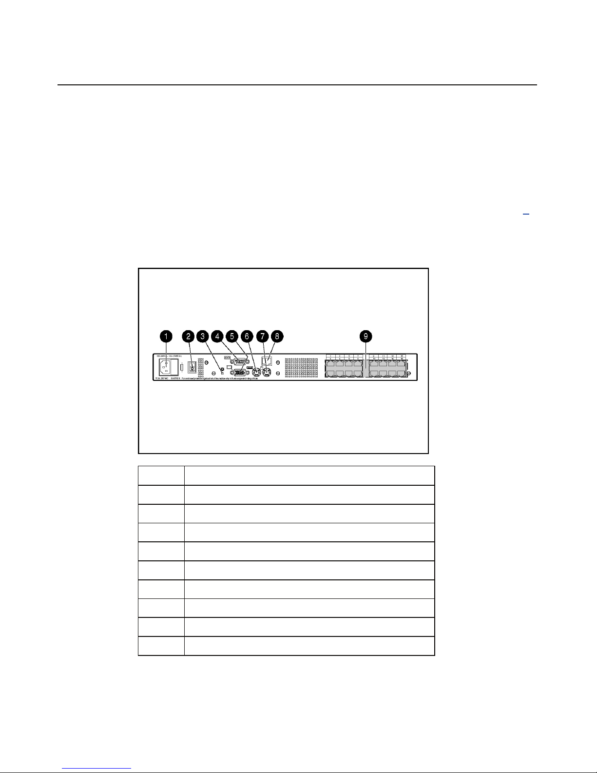
Components
Item Description
1 Power cord connector
2 Power switch
3 Activity indicator light
4 Serial port
5 Monitor connector for local user
6 Keyboard connector for local user
7 Mouse connector for local user
8 LAN connector
9 Server connection ports
Page 8
8 HP IP Console Switch User Guide
Item Description
1 CPU
2 HP IP Console Switch
3 IA
4 Network
5 Keyboard connector
6 Mouse connector
7 Video connector
Page 9

9
Installing the HP IP Console Switch
In This Section
Overview ........................................................................................................................................9
Installation Checklist ......................................................................................................................9
Rack Mounting the HP IP Console Switch...................................................................................10
Overview
You must install the HP IP Console Viewer before using the HP IP Console
Switch. The HP IP Console Viewer enables you to view and control a server
attached to the console switch system, configure and maintain the system, and
prevent unauthorized access to the console switch through IP connection. For
more information, refer to the HP IP Console Switch Software Guide included on
the CD provided with the console switch.
NOTE: The analog port does not require the HP IP Console Viewer
software for operation. The analog port uses the OSD. For more
information, refer to Local Port Operation (on page 45
page 45
).
The HP IP Console Switch system uses Ethernet networking infrastructures and
TCP/IP protocol to transmit keyboard, video, and mouse information between
operators and connected computers. Although 10Base-T Ethernet can be used, a
dedicated, switched 100Base-T network provides improved performance.
Installation Checklist
Before installation, refer to the following lists to be sure that all of the listed
components were received.
Kit Contents
• HP IP Console Switch
, "Overview" on
Page 10

10 HP IP Console Switch User Guide
• Power cords
• Rack mounting kit
• Serial download cable
• Documentation kit
• Firmware/software CD
Required Items Not Included
• PS/2 Interface Adapter or USB Interface Adapter
• UTP CAT5 cable (CAT6 and CAT7 may also be used)
Optional Items
• Expansion Module ("Installing the Expansion Module" on page 21)
• Serial Interface Adapter
Required Tools
The following tools are required for some procedures:
• Phillips screwdriver
• T-25 Torx screwdriver
Rack Mounting the HP IP Console Switch
The HP IP Console Switch ships with rack mounting brackets for easy
integration into the rack. Before installing the HP IP Console Switch and other
components in the rack cabinet (if not already installed), stabilize the rack in a
permanent location. Begin installing the equipment at the bottom of the rack
cabinet, then work to the top. Avoid uneven loading or overloading of the rack
cabinets.
Page 11

Installing the HP IP Console Switch 11
NOTE: Before installing the HP IP Console Switch into the rack,
connect the HP IP Console Switch to a power source, using the power
cords provided, and power on the unit. An activity indicator light
("Components" on page 7
activity indicator light does not display, be sure that the power is on, the
power cord is connected, and the power source is valid.
) is displayed after a few seconds. If the
Several rack mounting configurations include:
• Side-mount
− Type A—Square- and round-hole rails
− Type B—Square-hole rails
NOTE: The HP IP Console Switch cannot be side-mounted into a rack
with round-hole rails.
• Standard-mount
• Cantilever-mount
− Type A—Round-hole rails
− Type B—Square-hole rails
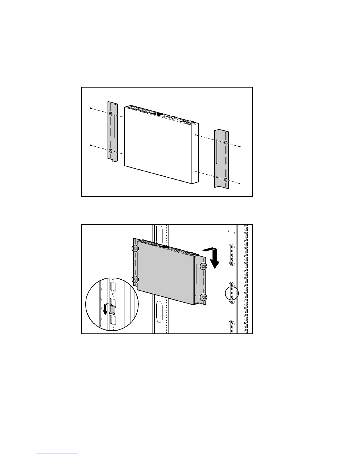
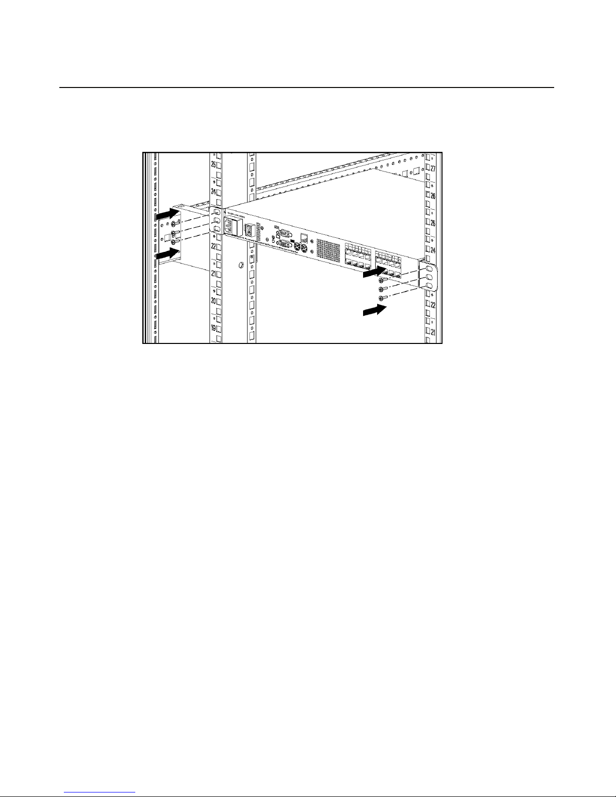
Performing a Side-Mount Type A Installation
1. Remove the four screws, two on each side, from the console switch.
Page 12
12 HP IP Console Switch User Guide
2. Attach the side-mounting brackets to the console switch using the four
screws you removed.
3. Slide the side-mounting bracket tabs into the U locations on each side of the
rack.
Page 13
Installing the HP IP Console Switch 13
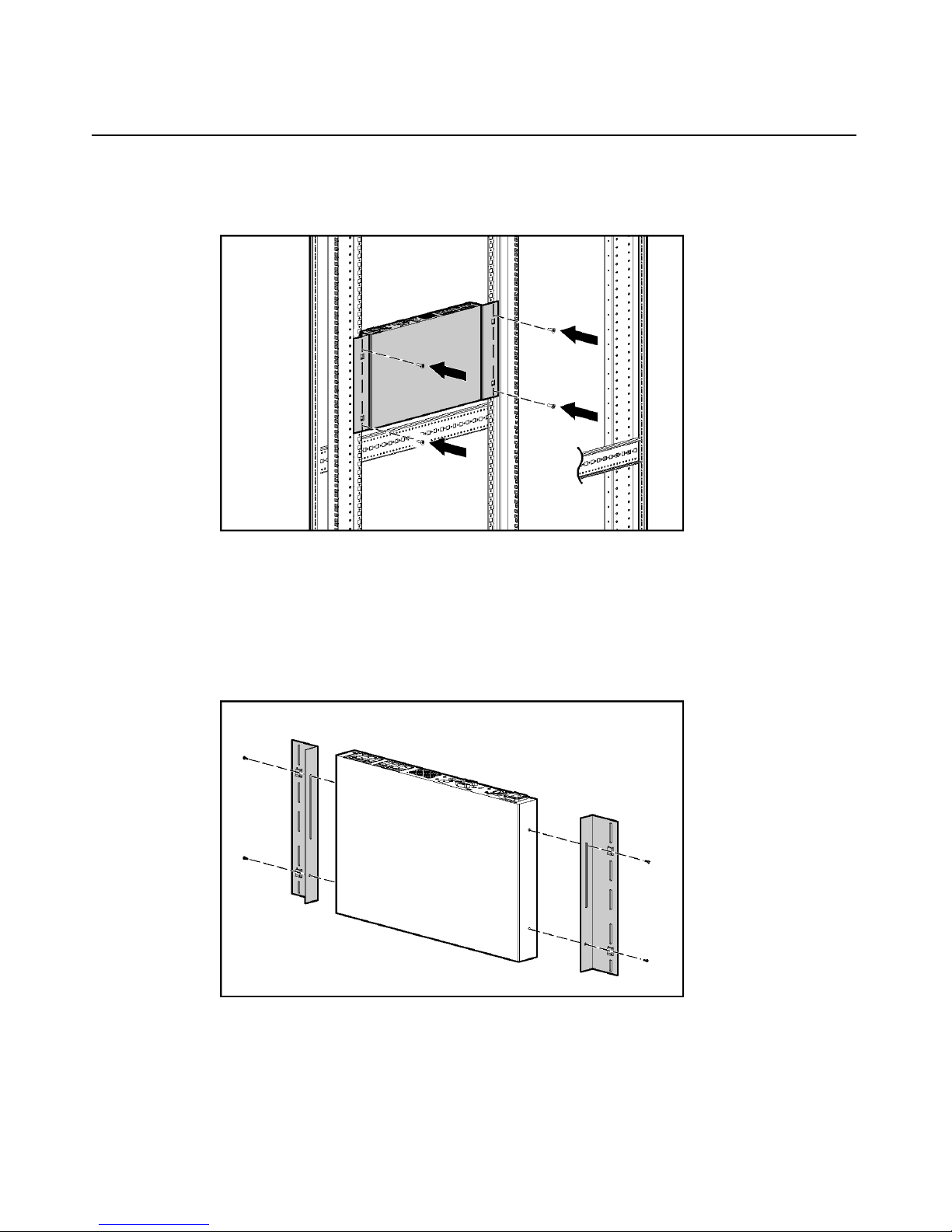
4. Secure the console switch to the rails using four self-tapping screws, two on
each side.
Performing a Side-Mount Type B Installation
1. Remove the four screws, two on each side, from the console switch.
2. Attach the side-mounting brackets to the console switch using the four
screws you removed.
Page 14
14 HP IP Console Switch User Guide
3. Slide the side-mounting bracket tabs into the U locations on each side of the
rack.
4. Install four cage nuts into the side-mounting bracket U locations.
5. Secure the console switch to the rails, using four M-6 screws, two on each
side.
Performing a Standard-Mount Installation
1. Remove the four screws, two on each side, from the console switch.
Page 15
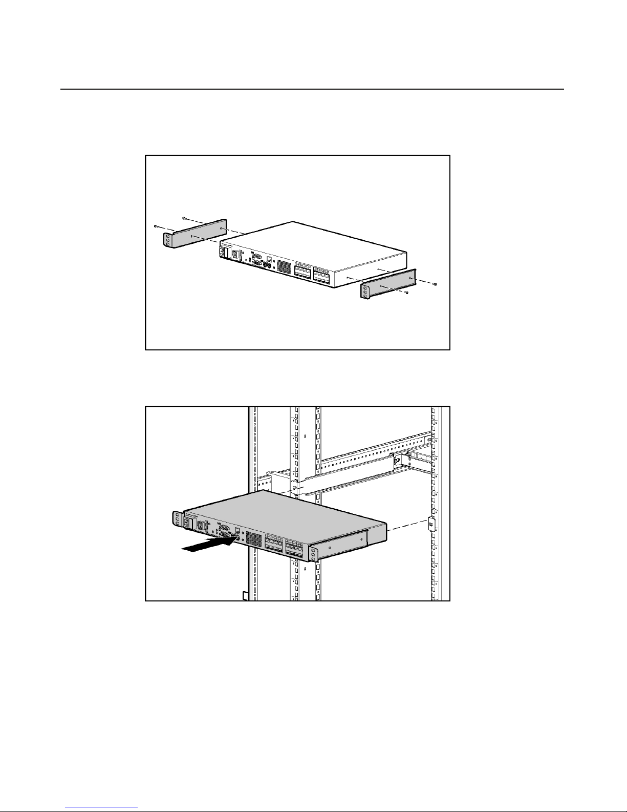
Installing the HP IP Console Switch 15
2. Attach the 1U brackets to the console switch using the four screws you
removed.
3. Install a cage nut behind each rear rail if they have not already been installed.
4. Slide the console switch into the rear of the 1U product.
Page 16
16 HP IP Console Switch User Guide
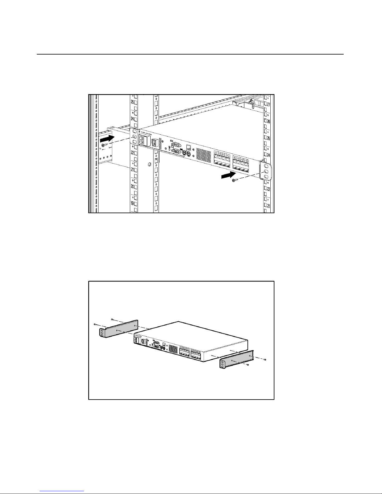
5. Secure the console switch to the rails using two M-6 screws, one on each
side.
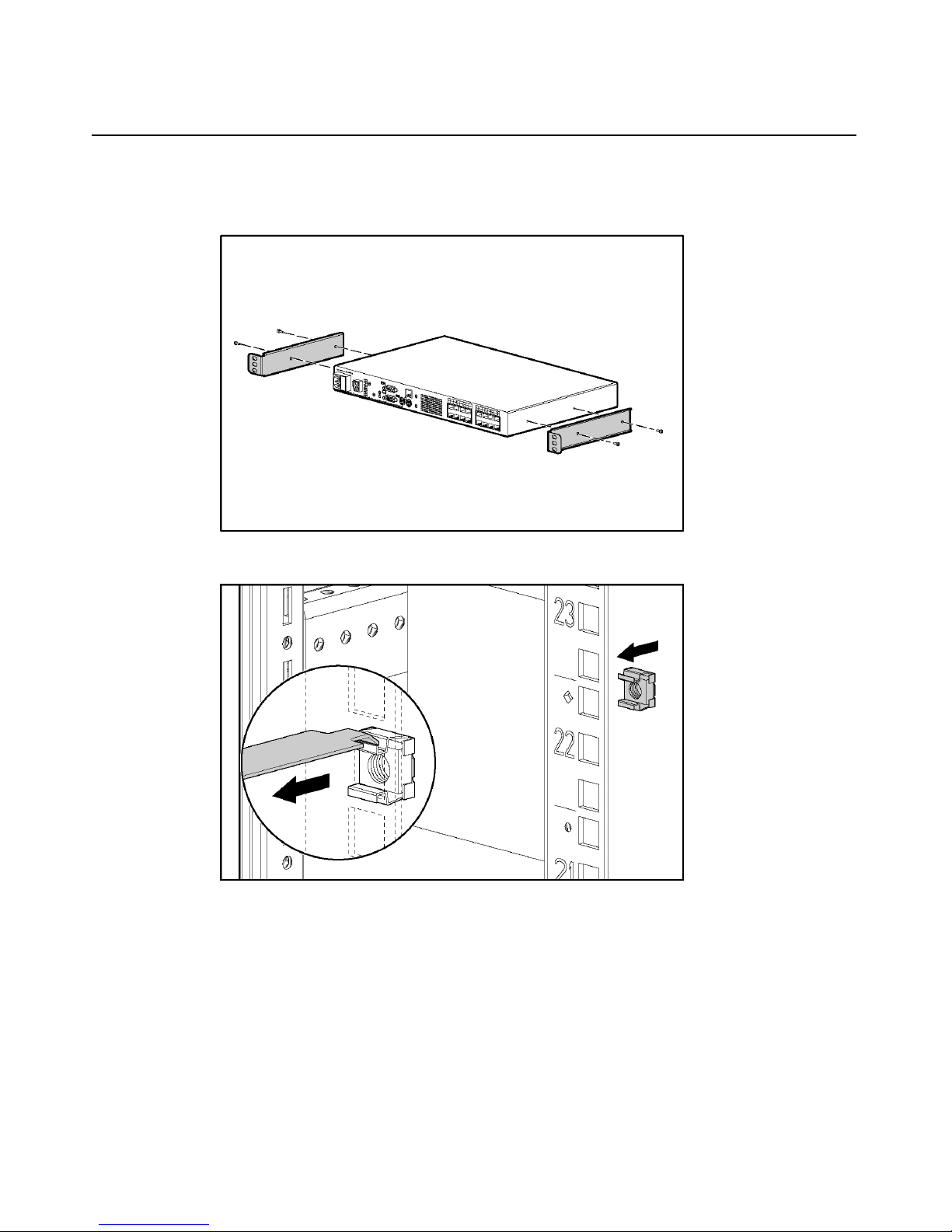
Performing a Cantilever-Mount Type A Installation
1. Remove the four screws, two on each side, from the console switch.
2. Attach the 1U brackets to the console switch using the four screws you
removed.
Page 17

Installing the HP IP Console Switch 17
3. Install up to six clip nuts.
4. Secure the console switch to the rails, using the appropriate number of T-25
Torx screws.
Performing a Cantilever-Mount Type B Installation
1. Remove the four screws, two on each side, from the console switch.
Page 18
18 HP IP Console Switch User Guide
2. Attach the 1U brackets to the console switch using the four screws you
removed.
3. Install up to six cage nuts.
Page 19
Installing the HP IP Console Switch 19
4. Secure the console switch to the rails using the appropriate number of M-6
screws.
Page 20

Page 21

21
Installing the Expansion Module
In This Section
Overview ......................................................................................................................................21
Installation Checklist ....................................................................................................................21
Installing the Expansion Module Hardware .................................................................................21
Configuring the Expansion Module .............................................................................................24
Overview
An optional Expansion Module can be added to the HP IP Console Switch
system, increasing the total number of accessible servers. The Expansion Module
ships with rack-mounting hardware for easy integration into the rack.
Installation Checklist
Before installation, refer to the following list to be sure that all of the listed
components were received.
Kit Contents
• Expansion Module
• Screws
• Velcro
This kit might contain extra hardware for your convenience.
Installing the Expansion Module Hardware
Several rack mounting configurations include:
• Side-mount
Page 22
22 HP IP Console Switch User Guide
• Rail-mount
• Velcro-mount
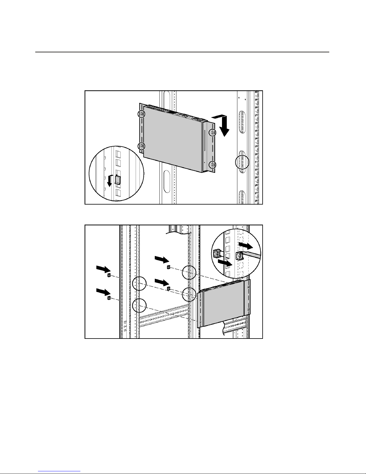
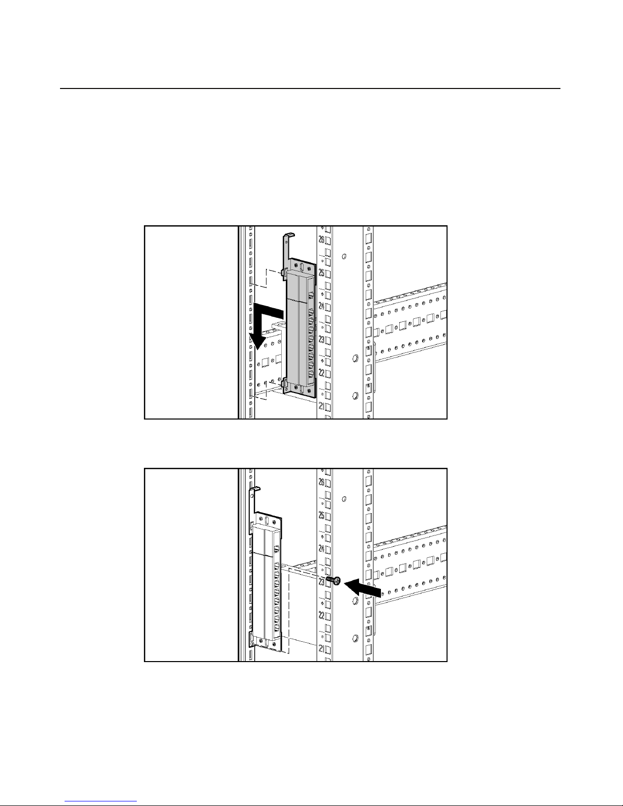
Performing a Side-Mount Installation
1. Slide the tabs on the side-mounting brackets into the rack frame.
2. Secure the Expansion Module to the rack frame, using one self-tapping screw
for the bottom side-mounting bracket.
Page 23
Installing the Expansion Module 23
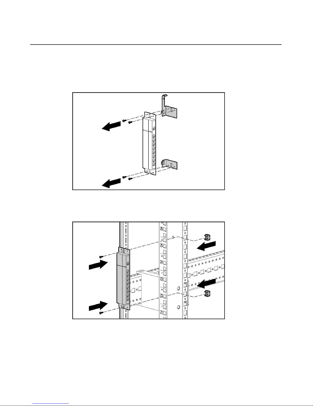
Performing a Rail-Mount Installation
1. Remove the screws securing the side-mounting brackets to the Expansion
Module.
2. Insert two cage nuts into the rack frame where the side-mounting bracket
holes are located and secure the Expansion Module to the rack frame, using
two M-6 screws.
Page 24
24 HP IP Console Switch User Guide
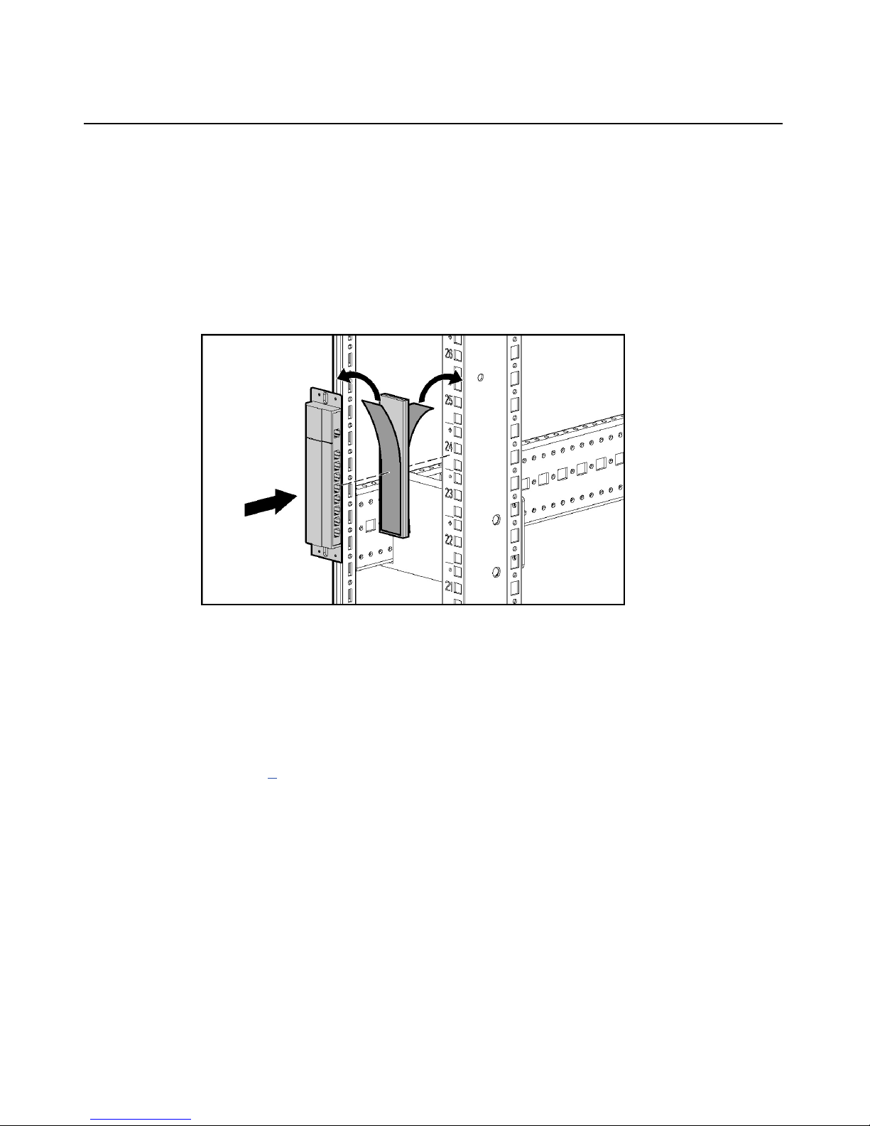
Performing a Velcro-Mount Installation
1. Determine the location for the Expansion Module.
2. Remove the protective strip from one side of the Velcro and attach that side
to the Expansion Module.
3. Remove the protective strip from the other side of the Velcro and attach the
Expansion Module to the rack frame.
Configuring the Expansion Module
1. Mount the Expansion Module into the rack.
2. Locate up to nine UTP CAT5 cables.
3. Connect a UTP CAT5 cable to the server connection port ("Components" on
page 7
4. Connect the other end of that same UTP CAT5 cable to the IN port on the
Expansion Module.
5. Connect one end of another UTP CAT5 cable to the OUT port on the
Expansion Module.
6. Connect the other end of the second UTP CAT5 cable to the Interface
Adapter.
7. Repeat steps 5 and 6 to connect any other servers to this system.
) on the HP IP Console Switch.
Page 25

25
Installing a PS/2 or USB Interface Adapter
In This Section
Overview ......................................................................................................................................25
Configuring the Interface Adapter................................................................................................25
Overview
An Interface Adapter is required for the HP IP Console Switch system to
function properly. However, it is not included in the HP IP Console Switch kit.
An Interface Adapter connects UTP CAT5 cables to PS/2 or USB connections,
establishing a KVM session to a server.
NOTE: UTP CAT5 cables are used throughout the examples in this
guide. However, UTP CAT6 and UTP CAT7 cables may also be used.
Configuring the Interface Adapter
1. Connect a UTP CAT5 cable to the server connection port ("Components" on
page 7
2. Connect the other end of that same UTP CAT5 cable to the RJ-45 port on the
Interface Adapter.
3. Connect the Interface Adapter to the appropriate ports on the server.
4. Repeat the preceding steps to connect any other servers to this system.
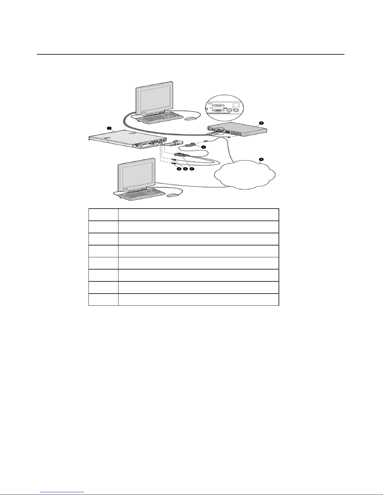
The following figure shows one possible configuration for the HP IP Console
Switch system with an Interface Adapter.
) on the HP IP Console Switch.
Page 26
26 HP IP Console Switch User Guide
Item Description
1 Server
2 HP IP Console Switch
3 USB Interface Adapter
4 PS/2 Interface Adapter
Page 27

27
Installing a Serial Interface Adapter
In This Section
Overview ......................................................................................................................................27
Installing the Serial Interface Adapter..........................................................................................28
Optimal Performance Settings......................................................................................................29
Serial Interface Adapter Modes....................................................................................................29
Serial Interface Adapter Pinouts...................................................................................................34
Attaching the Power Supply to the Rack Using Velcro ...............................................................34
Overview
The HP Serial Interface Adapter is a serial-to-VGA converter, which permits
VT100–capable devices to be viewed from the local ports of the HP IP Console
Switch and HP KVM Server Console Switch, or by using the HP IP Console
Viewer software. The serial data is not accessed but is displayed. All serial data
coming from the target device is displayed in a VT100 window, placed into a
video buffer, and sent to the console switch as though it came from a VGA
server. Keystrokes entered on a keyboard are sent to the attached device as
though they were entered into a VT100 terminal.
Page 28
28 HP IP Console Switch User Guide
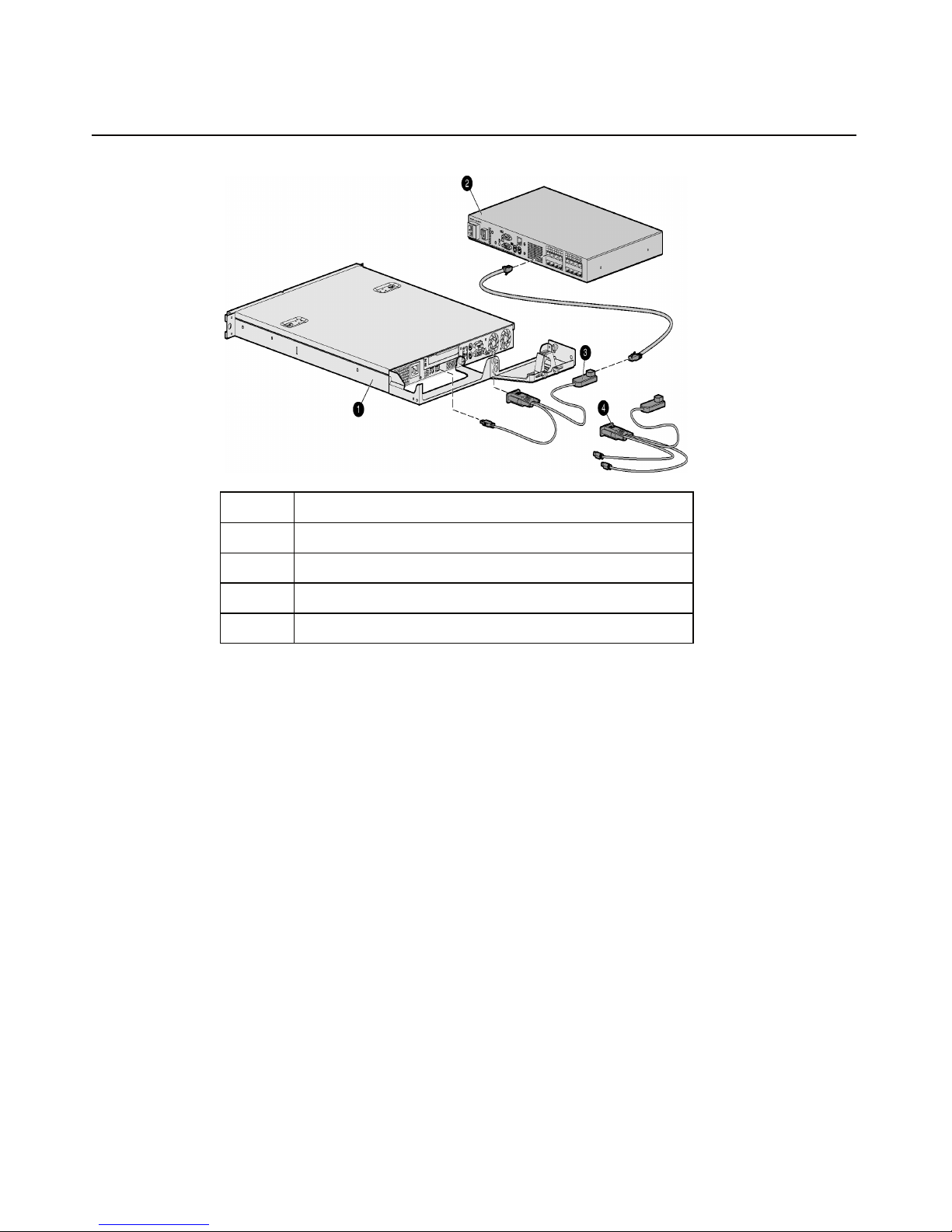
Installing the Serial Interface Adapter
Item Description
1 Serial device (target server)
2 Console Switch
3 Additional serial interface adapter
4 Serial interface adapter 9–pin connector
5 Serial interface adapter RJ-45 connector
6 Serial interface adapter power connector
7 Power expander
8 Power supply
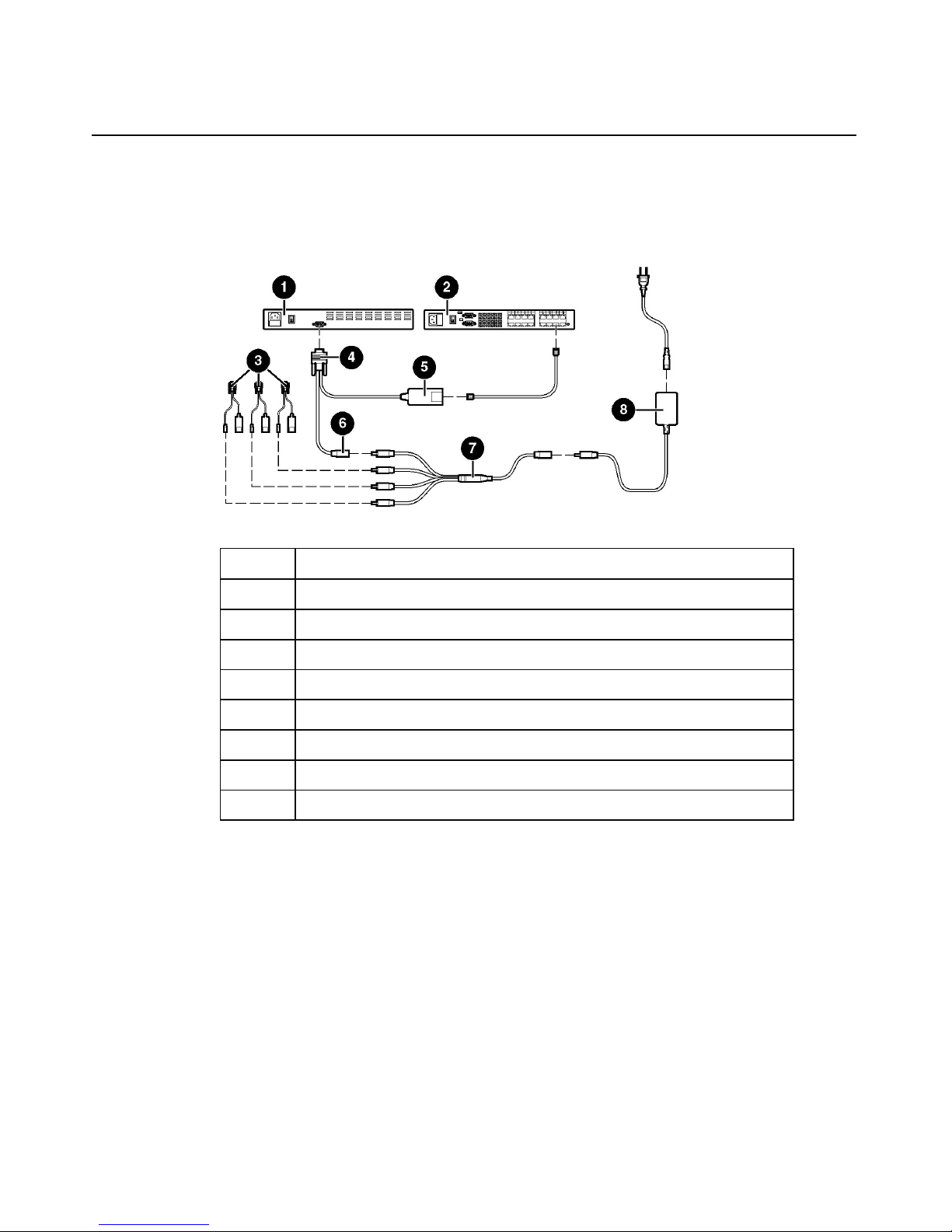
1. Power up the console switch.
2. Connect the serial interface adapter 9–pin connector (4) to the serial device
(1).
3. Connect the serial interface adapter (5) to the console switch (2) using a
CAT5 cable.
4. Connect the power supply (8) to either a power expander (7) or directly to
the serial interface adapter (6).
Page 29

Installing a Serial Interface Adapter 29
If you are using a power expander (7), connect it to up to three additional
serial interface adapters (3).
NOTE: Do not power more than four serial interface adapters from a
single power supply.
5. Repeat steps 2 through 4 to connect additional serial devices to the console
switch.
6. Connect the power supply (8) to an appropriate AC outlet.
7. Power up the serial device.
Optimal Performance Settings
The following settings are required for optimal serial interface adapter
performance:
• Flow Control is required to ensure reliable data flow. Buffer overflows might
cause a loss of communication, which might require a power cycling of the
serial interface adapter. Set the flow control on the target device, if available,
to match the serial interface adapter. If the target device does not support
flow control, use the lowest baud rate available.
• VT100 Terminal Emulation is the only emulation supported. Be sure your
target device is configured for VT100 terminal emulation.
• Automatic Video Adjust is required to optimize video settings. When using
the HP IP Console Viewer software to connect to a serial interface adapter,
using the Remote Video Session, perform an automatic video adjust
(Tools>Automatic Video Adjust).
Serial Interface Adapter Modes
The following modes can be accessed through the serial interface adapter:
• Online Mode—This mode enables you to send and receive serial data.
• History Mode—This mode enables you to examine the contents of the
history buffer, which contains the events that have occurred.
Page 30

30 HP IP Console Switch User Guide
• Configuration Mode—This mode enables you to specify communication
parameters, the appearance of serial data, and key combinations for specific
actions and macros.
History Mode
The serial interface adapter maintains a buffer containing 240 lines minimum, or
10 screens, of output. When the history buffer is full, it adds new lines at the
bottom of the buffer and deletes the oldest lines at the top of the buffer.
Using History Mode
1. Press the Ctrl+F9 keys. The mode appears as History.
2. Press one of the following key combinations to perform the indicated action:
− Home—Move to the top of the buffer
− End—Move to the bottom of the buffer
− Page Up—Move down one buffer page
− Page Down—Move down one buffer page
− Up Arrow—Move up one buffer line
− Down Arrow—Move down one buffer line
− Ctrl+F8—Enter Configuration mode (the Configuration menu appears)
− Ctrl+F9—Return to the previous screen with History mode enabled
− Ctrl+F10—Return to the previous screen with Online mode enabled
− Ctrl+F11—Clear the history buffer (if you choose this option, a warning
screen appears. Press the Enter key to delete the history buffer, or the
Esc key to cancel the action. The previous screen appears again)
3. When finished, press the Ctrl+F10 keys to exit History mode and return to
Online mode.
Page 31

Installing a Serial Interface Adapter 31
Configuration Mode
Press the Ctrl+F8 keys to activate the Configuration menu. The Configuration
menu contains menu items that enable you to configure your serial interface
adapter.
Communication Parameters
The following communication parameters can be changed through the
Configuration Mode:
• Baud Rate—This option enables you to specify the serial port
communication speeds in bits per second (BPS). Available options are 300,
1200, 2400, 9600, 19200, 34800, 57600, or 115200. The default value is
9600.
• Parity—This option enables you to specify the serial port communications
parity. Available options are EVEN, ODD, or NONE. The default value is
NONE.
• Flow Control—This option enables you to specify the type of serial flow
control. Available options are NONE, XOn/XOff (software), and RTS/CTS
(hardware). The default value is NONE. If you select a baud rate of 115200,
the only available flow control is RTS/CTS (hardware).
• DSR/CD Mode—This option enables you to control how the DSR and CD
lines operate. Available options are Always On mode and Toggle mode.
When in Toggle mode, the DSR and CD lines are turned off for one-half
second and then turned on each time a module is selected or deselected. The
default value is Always On mode.
• Enter Sends—This option enables you to specify the keys that are
transmitted when the Enter key is pressed. Available options are <CR>
(Enter) or <CR><LF> (Enter—Linefeed).
• Received—This option enables you to specify how the serial interface
adapter translates a received Enter. Available options are <CR> (Enter) or
<CR><LF> (Enter—Linefeed).
• Background—This option changes the color of the background screen. The
currently selected color displays in the option line as it is changed. This color
cannot be identical to the Normal Text or Bold Text color.
Page 32

32 HP IP Console Switch User Guide
• Normal Text—This options changes the normal text color of the screen. The
currently selected color displays in the option line as it is changed. This color
cannot be identical to the Bold Text or Background color.
• Bold Text—This options changes the bold text color of the screen. The
currently selected color displays in the option line as it is changed. This color
cannot be identical to the Normal Text or Background color.
• Screen Size—This option enables you to specify the text width size of the
screen. Available widths are 80 columns or 132 columns. The length for both
widths is 26 lines.
Function Keys
The following options of the Configuration menu enable you to define the
function keys that perform selected actions.
To specify a new function key, press and hold the Ctrl key, then press the
function key that you want to associate with the action. For example, if you want
to change the Config Key Sequences option from Ctrl+F8 to Ctrl+F7, press and
hold the Ctrl key and then press the F7 key.
• Config Key Sequences—This options enables you to define the key
combination that causes the Configuration screen to appear.
• Online Key Sequence—This option enables you to define the key sequence
that displays the Online mode. The default key sequence is Ctrl+F10.
• Help Key Sequence—This option enables you to define the key combination
that displays the Help System screen. The default key sequence is Ctrl+F1.
• History Key Sequence—This option enables you to define the key
combination that enables History mode. The default key sequence is Ctrl+F9.
• Clear History Key Sequence—This option enables you to define the key
combination that clears the history buffer while in History mode. The default
key is Ctrl+F11.
• Break Key Sequence—This options enables you to configure the key
combination that generates a break condition. The default key sequence is
Alt+B.
Page 33

Installing a Serial Interface Adapter 33
Using Configuration Mode
1. Press the Ctrl+F8 keys. The Configuration screen appears.
2. Select a parameter to change. You can navigate the configuration screen
using the up arrow and down arrow.
3. Modify the selected value using the left arrow and right arrow.
4. Repeat steps 2 and 3 to modify additional values.
5. Press the Enter key to save you changes and exit.
-orPress the Esc key to exit the configuration screen without saving the
changes.
Serial Interface Adapter Macros
Press the Page Down key when the Configuration menu appears to provide
access to the Macro Configuration screen. The serial interface adapter can be
configured with up to 10 macros. Each macro can be up to 128 characters in
length.
Creating Macros
1. Select the serial interface adapter you want to configure and press the
Ctrl+F8 keys. The Configuration menu appears.
2. Press the Page Down key. The Macro Configuration screen appears. The
Macro Configuration screen displays the 10 available macros and the
associated key sequences.
3. Using the Arrow keys, scroll to an available macro number and highlight the
listed keystroke sequence.
4. Enter the new macro sequence over the default. Any combination of Ctrl or
Alt and a single key can be used.
5. When you have finished entering the keystroke sequences that activate the
new macro, press the down arrow key.
6. On the line below the macro keystroke sequence just entered, enter the
keystroke sequence that you want the macro to perform.
7. Repeat this sequence for each macro that you want to configure.
Page 34

34 HP IP Console Switch User Guide
8. When finished, press the Enter key to return to the Terminal screen.
Serial Interface Adapter Pinouts
The serial interface adapter is a DCE device. The following table lists the pinouts
for the serial interface adapter.
DB9F Pin Serial Interface Adapter Description
1 Data Terminal Ready (DTR)
Pins 6 and 1 are tied common internal to the serial interface
idapter.
2 Transmit Data (TXD)
3 Receive Data (RXD)
4 Data Set Ready (DSR)
5 Signal Ground (GND)
6 Data Terminal Ready (DTR)
7 Clear to Send (CTS)
8 Request to Send (RTS)
9 Not Connected (N/C)
Attaching the Power Supply to the Rack Using Velcro
1. Determine the location for the power supply.
2. Remove the protective strip from one side of the Velcro and attach that side
to the power supply.
Page 35

Installing a Serial Interface Adapter 35
3. Remove the protective strip from the other side of the Velcro and attach the
power supply to the rack frame.
Page 36

Page 37

37
Cascading Console Switches
In This Section
Compatible Console Switch Models ............................................................................................37
Cascading a Compaq Server Console Switch with an HP IP Console Switch .............................39
Cascading an HP KVM Server Console Switch with an HP IP Console Switch .........................41
Compatible Console Switch Models
Review the following information before cascading console switches with this
product.
This product supports only one level of cascading. An Expansion Module is
considered a level of cascading and therefore cannot be used in combination with
cascaded console switches.
To ensure optimum equipment performance while cascading console switches,
follow the proper powering-on sequence—power on the console switches,
monitor, and then servers.
NOTE: The HP IP Console Switch does not support Compaq KVM PCI
Cards or HP legacy console switches.
Compaq Server Console Switch
CAUTION: While cascading a 2 x 8 Compaq Server Console
Switch, connect only one Interface Adapter at any given time.
Undesirable operations might occur if multiple Interface Adapters are
attached.
CAUTION: While cascading console switches, be sure that
the Compaq Server Console Switch is cascaded below the HP IP
Console Switch. Undesirable operations might occur if these specific
cascading sequences are not followed.
Page 38

38 HP IP Console Switch User Guide
The following Compaq Server Console Switches can be integrated into the HP IP
Console Switch system. Compatible Compaq Server Console Switch models
include:
• 1 x 4 [PN: 400336 (-001)(-291)(-B31)]
• 1 x 8 [PN: 400337 (-001)(-291)(-B31)]
• 2 x 8 [PN: 400338 (-001)(-291)(-B31)]
• 2 x 8 48 VDC [PN: 400542 -B21]
All Compaq Server Console Switches must be upgraded with SoftPaq firmware,
version 2.1.0 or later, when cascaded with this product.
HP KVM Server Console Switch
CAUTION: Do not use Interface Adapters to cascade HP IP
Console Switches with HP KVM Server Console Switches. If Interface
Adapters are used to cascade these products, undesirable operations
might occur.
CAUTION: While cascading console switches, be sure that
the HP KVM Server Console Switch is cascaded below the HP IP
Console Switch. Undesirable operations might occur if these specific
cascading sequences are not followed.
NOTE: To perform a firmware upgrade for a cascaded HP KVM Server
Console Switch and all attached Interface Adapters, you must locally
connect the keyboard, monitor, and mouse to the cascaded HP KVM
Server Console Switch to access the local OSD.
The following HP KVM Server Console Switches can be integrated into the HP
IP Console Switch system. Compatible HP KVM Server Console Switch models
include:
• 1 x 8 [PN: 336044 (-B21)]
• 2 x 16 [PN: 336045 (-B21)]
All HP KVM Console Switches must be upgraded with SoftPaq firmware,
version 2.0.6 or later, when cascaded with this product.
Page 39

Cascading Console Switches 39
Cascading a Compaq Server Console Switch with an
HP IP Console Switch
1. Mount the console switches in the rack.
2. Connect the local port KVM cable to the HP IP Console Switch.
3. Connect a UTP CAT5 cable to the server connection port ("Components" on
page 7
4. Connect the other end of that same UTP CAT5 cable to the RJ-45 port on the
Interface Adapter.
5. Connect the Interface Adapter to the IN port (designated by the letter A) on
the Compaq Server Console Switch.
6. Connect a KVM cable to the numbered OUT port on the Compaq Server
Console Switch.
7. Connect the other end of that same KVM cable to the appropriate port on the
server.
) on the HP IP Console Switch.
8. Repeat steps 3 through 7 for any other console switches to be added to this
system.
9. Power on the console switches.
10. Power on the monitor.
11. Power up the server.
Page 40

40 HP IP Console Switch User Guide
The following figure shows a Compaq Server Console Switch cascaded to an HP
IP Console Switch. The top console switch is the main console switch, while the
bottom console switch is the cascaded console switch.
Example of a Compaq Server Console Switch Cascade
Configuration
Page 41

Cascading Console Switches 41
Item Description
1 Server
2 KVM cable
3 PS/2 Interface Adapter
4 UTP CAT5 cable
5 Cascaded Compaq Server Console Switch
6 Local port
7 Main HP IP Console Switch
Cascading an HP KVM Server Console Switch with
an HP IP Console Switch
NOTE: To perform a firmware upgrade for a cascaded HP KVM Server
Console Switch and all attached Interface Adapters, you must locally
connect the keyboard, monitor, and mouse to the cascaded HP KVM
Server Console Switch to access the local OSD.
1. Mount the console switches in the rack.
2. Locate a UTP CAT5 cable and connect one end to the server connection port
("Components" on page 7
) on the cascaded HP KVM Server Console Switch.
3. Connect the other end of that same UTP CAT5 cable to the RJ-45 port on the
Interface Adapter.
4. Connect the Interface Adapter to the appropriate ports on the server.
5. Repeat steps 1 through 3 for any other servers to be added to this system.
6. Connect the local port KVM cable to the cascaded HP KVM Server Console
Switch.
7. Power on the cascaded HP KVM Server Console Switch.
8. Power on the monitor.
9. Power up the server.
10. Update the cascaded HP KVM Server Console Switch firmware.
11. Update all Interface Adapter firmware.
Page 42

42 HP IP Console Switch User Guide
12. Power off the cascaded HP KVM Server Console Switch.
13. Power off the monitor.
14. Disconnect the local KVM cables from the cascaded HP KVM Server
Console Switch.
15. Connect the local port KVM cable to main HP IP Console Switch.
16. Connect a UTP CAT5 cable to the server connection port ("Components" on
page 7
) on the main HP IP Console Switch.
17. Connect the other end of that same UTP CAT5 cable to the RJ-45 interface
port ("Components" on page 7
Switch.
18. Repeat steps 15 and 16 for any other console switches to be added to this
system.
19. Power on the console switches.
20. Power on the monitor.
) on the cascaded HP KVM Server Console
21. Update the main HP IP Console Switch firmware (refer to the HP IP Console
Switch documentation).
22. Update all Interface Adapter firmware.
The following figure shows an HP IP Console Switch cascaded to an HP KVM
Server Console Switch. The top console switch is the main console switch, while
the bottom console switch is the cascaded console switch.
Page 43

Cascading Console Switches 43
CAUTION: Do not use Interface Adapters to cascade HP IP
Console Switches with HP KVM Server Console Switches. If Interface
Adapters are used to cascade these products, undesirable operations
might occur.
Example of an HP IP Console Switch Cascade Configuration
Page 44

44 HP IP Console Switch User Guide
Item Description
1 Server
2 PS/2 Interface Adapter or USB Interface Adapter*
3 UTP CAT5 cable
4 UTP CAT5 cable
5 KVM cable
6 Main HP IP Console Switch
7 Local port
8 Cascaded HP KVM Server Console Switch
* not shown
Page 45

45
Local Port Operation
In This Section
Overview ......................................................................................................................................45
Soft Switching ..............................................................................................................................50
Using Basic OSD Navigation Keys..............................................................................................51
Configuring the Setup Dialog Box ...............................................................................................52
Managing Server Tasks Using the OSD.......................................................................................74
Overview
The HP IP Console Switch system has one local port on the rear panel
("Components" on page 7
) that enables the user to connect a keyboard, monitor,
and mouse to the HP IP Console Switch for direct access.
Use the Main dialog box ("Accessing the Main Dialog Box" on page 45
configure, and control servers in the HP IP Console Switch system. You can also
clear offline Interface Adapters, without having to go to the Diagnostics dialog
box, by clicking the Clear button.
Accessing the Main Dialog Box
Press the Print Scrn key. The Main dialog box appears.
) to view,
Page 46

46 HP IP Console Switch User Guide
NOTE: You can also press the Ctrl key twice within one second to
launch the OSD. You can use this key sequence in any place you see
Print Scrn.
Viewing and Selecting Ports and Servers
You can view servers by name, port, or by the unique EID embedded in each
Interface Adapter.
Viewing the Port Column
When the Main dialog box ("Accessing the Main Dialog Box" on page 45
first launched, an OSD-generated port list is displayed by default.
) is
Page 47

Local Port Operation 47
The Port column indicates the port to which a server is connected. For example,
in the following screen shot, the first number represents the port number of the
first console switch and the second number represents the port number of the
cascaded console switch port to which the server is connected.
Port number
of the first
console
switch
Port number
of the
cascaded
console
switch
Server
Status Icon
displayed
Description
16 01
14 02 The server is connected to port 02 of the 2 x 16 HP
01 04 The server is connected to port 04 of the Compaq
02
02
The server is connected to port 01 of the 1 x 8 HP
KVM Server Console Switch, and that HP KVM
Server Console Switch is cascaded from port 16 of
the first HP KVM Server Console Switch.
KVM Server Console Switch, and that HP KVM
Server Console Switch is cascaded from port 14 of
the first HP KVM Server Console Switch.
Server Console Switch, and that Compaq Server
Console Switch is cascaded from port 01 of the first
HP KVM Server Console Switch.
The servers are connected to an Expansion Module
so they are using the same port. You can tell that
the Expansion Modules are not cascaded because
they do not have the second port numbers.
The servers are connected to an Expansion Module
so they are using the same port. You can tell that
the Expansion Modules are not cascaded because
they do not have the second port numbers.
Page 48

48 HP IP Console Switch User Guide
Port number
of the first
console
switch
Port number
of the
cascaded
console
Server
Status Icon
displayed
Description
switch
04
The server is connected to the first console switch
and the Interface Adapter is not connected or the
server is powered off.
05 The server is connected to the first console switch
and is active.
Viewing the Server Status Column
The status of the servers in the HP IP Console Switch system are indicated by the
icons in the right column of the Main dialog box ("Accessing the Main Dialog
Box" on page 45
Item Description
).
The Interface Adapter is connected directly, cascaded
through an HP IP Console Switch or an Expansion
Module, or powered on.
(C or D may also
appear)
The Interface Adapter is not connected or the server
is powered off.
The Interface Adapter is cascaded to a Compaq
Server Console Switch and the server is not
connected or is powered off.
The Interface Adapter is cascaded to a Compaq
Server Console Switch and the server is connected or
is powered on.
The Interface Adapter is being upgraded.
A symbol that identifies which port the console switch
is connected to.
A symbol that identifies which port you are actively
connected to and viewing.
A symbol that identifies a remote session connected
to that server.
Page 49

Local Port Operation 49
Selecting Servers
From the Main dialog box ("Accessing the Main Dialog Box" on page 45
), users
can select specific servers. When a new server is selected, the console switch
reconfigures the KVM to the setting for the selected server.
Double-click the server Name, EID, or Port number.
-or-
If the display order of the server list is by Port (the Port button is clicked), enter
the port number and press the Enter key.
-or-
If the display order of the server list is by Name or EID number (the Name or
EID button is clicked), enter the first few letters of the name of the server or the
EID number to establish it as unique, and then press the Enter key.
NOTE: The EID is an electronic identification number, found on the
Interface Adapter cable label, automatically assigned to the Interface
Adapter.
Selecting Previous Servers
Press the Print Scrn key, then press the Backspace key. This key combination
toggles between the previous and current connection.
Disconnecting from a Server
Press the Print Scrn key, then press the Alt + 0 keys.
-or-
Click Disconnect.
This leaves no server selected and in a free state. The status flag ("Controlling
the Status Flag" on page 55
) on the OSD displays Free.
Page 50

50 HP IP Console Switch User Guide
Soft Switching
Soft switching is the ability to switch servers using a hotkey sequence. You can
soft switch to a server by pressing the Print Scrn key and entering the first few
characters of its name or number. If you have set a Screen Delay Time and you
press the key sequences before that time has elapsed, the OSD does not display.
Configuring Servers for Soft Switching
1. From the Main dialog box ("Accessing the Main Dialog Box" on page 45),
click Setup>Menu. The Menu dialog box is displayed.
2. For Screen Delay Time, enter the number of seconds of delay desired before
the Main dialog box displays after the Print Scrn key is pressed.
3. Click OK to save settings.
Soft Switching to a Server
To select a server, press the Print Scrn key. If the display order of your server
list is by Port (the Port button is clicked), enter the port number and press the
Enter key.
-or-
If the display order of the server list is by Name or EID number (the Name or
EID button is clicked), enter the first few letters of the name of the server or the
EID number to establish it as unique, and then press the Enter key.
Soft Switching to a Previous Server
Press the Print Scrn key, then press the Backspace key. This key combination
toggles between the previous and current connection.
Page 51

Local Port Operation 51
Using Basic OSD Navigation Keys
Keystroke Description
Print Scrn Opens the OSD Main dialog box. Press the Print Scrn key twice to send
the Print Scrn keystroke to the currently selected device.
F1
Esc
Alt
Alt + X
Alt + 0 Selects the OK button and returns to the previous dialog box.
Enter
Single-click, Enter
Print Scrn, Backspace
Print Scrn, Alt + 0
Opens the Help screen for the current dialog box.
Closes the current dialog box without saving changes and returns to the
previous dialog box. In the Main dialog box, it closes the OSD and returns
to the selected server. In a message box, it closes the pop-up box and
returns to the current dialog box.
Opens dialog boxes, selects options, and executes actions, when used in
combination with the other keys.
Closes the current dialog box and returns to the previous dialog box.
Completes the console switch operation in the Main dialog box and exits
the OSD.
Selects the text, in a text box, for editing and enables the left and right
arrow keys to move the cursor. Press the Enter key again to quit Edit
mode.
Toggles back to the previous selection if no other keystrokes have been
entered.
Disengages the user immediately from a server—no server is selected.
Status Flag displays Free. (This only applies to the 0 on the keyboard, not
the keypad.)
Print Scrn, Pause
Up or Down arrows
Right or Left arrows
Page Up or Page Down
Home or End
Backspace
Delete
Activates the Screen Saver mode immediately and prevents access to
that particular console if it is password protected.
Moves the cursor from line to line.
Moves the cursor between columns. When editing a text box, these keys
move the cursor within the column.
Pages up and down through Name and Port lists.
Moves the cursor to the top or bottom of a list.
Erases characters in a text box.
Deletes current selection in the Scan dialog box or characters in a text
box.
Page 52

52 HP IP Console Switch User Guide
Keystroke Description
Shift, Delete
Numbers
Caps Lock Disables the user. (Use the Shift key to change case.)
Deletes from current selection to all lines below it when editing a scan list.
Adds numbers from the keyboard or keypad.
Configuring the Setup Dialog Box
You can configure the HP IP Console Switch and manage routine tasks for your
servers from the Setup dialog box ("Accessing the Setup Dialog Box" on page
52) within the OSD. Click Names when initially setting up your console switch
to identify servers by unique names.
Accessing the Setup Dialog Box
From the Main dialog box ("Accessing the Main Dialog Box" on page 45), click
Setup. The Setup dialog box appears.
Page 53

Local Port Operation 53
Managing Routine Tasks for Servers
Button Function
Menu
Flag
Broadcast
Scan
Security
Preempt
Keyboard
Devices
Names
Changes the server listing between numerically by port or EID number and
alphabetically by name.
Changes the delay time before the Main dialog box displays after pressing the Print
Scrn key.
Changes the display, timing, color, and location of the status flag.
Controls multiple servers simultaneously through keyboard and mouse actions.
Sets up custom scan patterns for up to 16 servers.
Sets password to restrict server access and enables screen saver. A valid password
must be alphanumeric and contain a minimum of five characters and a maximum of 15
characters. Permitted characters are case-sensitive and can consist of A–Z, 0–9,
spaces, and hyphens.
Enables the Screen Saver mode.
Allows the local user to set the Preempt Timeout value.
Changes the keyboard country code reported by the Interface Adapter if queried.
Identifies device types attached to the HP IP Console Switch, including servers and
other console switches.
Allows you to name Interface Adapters.
Changing the Display Behavior
From the Menu dialog box ("Accessing the Menu Dialog Box" on page 54), the
display order of servers, HP IP Console Switch connection mode, and a time to
delay display of the OSD after pressing the Print Scrn key can be changed. The
display order setting alters how servers display in several screens, including the
Main, Devices, and Broadcast dialog boxes.
Page 54

54 HP IP Console Switch User Guide
Accessing the Menu Dialog Box
From the Main dialog box ("Accessing the Main Dialog Box" on page 45
Setup>Menu. The Menu dialog box is displayed.
Selecting the Display Order of Servers
), click
1. From the Menu dialog box ("Accessing the Menu Dialog Box" on page 54
),
select Name to display servers alphabetically by name.
-orSelect EID to display servers numerically by Interface Adapter ID number.
-orSelect Port to display servers numerically by port number.
2. Click OK to save settings.
-orClick X to exit, or press the Esc key to exit without saving settings.
Page 55

Local Port Operation 55
Setting a Screen Delay Time
Setting a time to delay the display of the OSD enables you to complete a soft
switch ("Soft Switching" on page 50) without displaying the OSD. It is strongly
recommended to leave the number of seconds (0-9) the OSD is delayed to the
default (0).
1. From the Main dialog box ("Accessing the Main Dialog Box" on page 45
enter the number of seconds (0–9) the OSD is delayed after pressing the
Print Scrn key. Entering 0 instantly displays the OSD with no delay.
2. Click OK to save settings.
-orClick X to exit, or press the Esc key to exit without saving settings.
Controlling the Status Flag
The status flag is displayed on the desktop and shows the Name or EID number
of the selected server or the status of a particular port. Use the Flag dialog box
("Accessing the Flag Dialog Box" on page 56
server name or EID number or to change the flag color, opacity, display time,
and location on the desktop.
Flag Description
Flag type by name
),
) to change the flag display by
Flag type by EID number
Flag indicating that the user has been disconnected from all
systems
Flag indicating that the broadcast is activated
Control used to set flag position
Page 56

56 HP IP Console Switch User Guide
Accessing the Flag Dialog Box
From the Main dialog box ("Accessing the Main Dialog Box" on page 45
Setup>Flag. The Flag dialog box is displayed.
Displaying the Status Flag
), click
1. From the Flag dialog box ("Accessing the Flag Dialog Box" on page 56
),
select Name or EID to determine what information is displayed.
2. Select Displayed to show the flag constantly, or select Timed to display the
flag for only five seconds after soft switching.
3. Select a flag color in Display Color.
4. In the Display Mode, select Opaque for a solid-color flag or Transparent to
see the desktop through the flag.
5. Position the status flag on the desktop:
a. Click Set Position to gain access to the Position Flag screen.
b. Left-click and hold the title bar and drag to the desired location.
c. Right-click to return to the Flag dialog box.
Page 57

Local Port Operation 57
6. Click OK to save settings.
-orClick X to exit, or press the Esc key to exit without saving settings.
NOTE: Changes made to the position flag are not saved until you click
OK in the Flag dialog box ("Accessing the Flag Dialog Box" on page
56
).
Broadcasting to Servers
Analog users can simultaneously control more than one server in a system to be
sure that all selected servers receive identical input. For each server receiving the
broadcast, you can choose to broadcast keystrokes and mouse movements
independently.
NOTE: During broadcast, any users connected to a broadcast server
will be disconnected and unable to access any servers.
NOTE: You can broadcast to only one server per Expansion Module
("Installing the Expansion Module" on page 21
) connection.
Broadcasting Keystrokes
The keyboard statistics must be identical for all servers receiving a broadcast to
interpret keystrokes identically. Specifically, the Caps Lock and Num Lock
modes must be the same on all keyboards. While the HP IP Console Switch
attempts to send keystrokes to the selected servers simultaneously, some servers
can inhibit and thereby delay the transmission.
Broadcasting Mouse Movements
For the mouse to work accurately, all systems must have identical mouse drivers,
desktops (such as identically placed icons), and video resolutions. In addition, the
mouse must be in exactly the same place on all screens. Because these conditions
are extremely difficult to achieve, broadcasting mouse movements to multiple
systems can have unpredictable results.
Accessing the Broadcast Dialog Box
From the Main dialog box ("Accessing the Main Dialog Box" on page 45
Setup>Broadcast. The Broadcast dialog box is displayed.
), click
Page 58

58 HP IP Console Switch User Guide
Broadcasting Selected Servers
1. From the Broadcast dialog box ("Accessing the Broadcast Dialog Box" on
page 57
), select the keyboard and mouse checkboxes for the servers that are
to receive the broadcast commands.
-orPress the Up or Down Arrow keys to move the cursor to the target server.
Then press the Alt + K keys to select the keyboard checkbox and/or the Alt
+ M keys to select the mouse checkbox. Repeat for additional servers.
2. Click OK to save the settings and return to the Setup dialog box.
3. Click X or press the Esc key to return to the Main dialog box.
4. From the Main dialog box, click the Commands dialog box ("Accessing the
Commands Dialog Box" on page 75
broadcasting.
5. From the user station, enter the information and/or perform the mouse
movements you want to broadcast.
), select Broadcast Enable to activate
Page 59

Local Port Operation 59
Activating the Broadcast Dialog Box
To activate or deactivate broadcasting, from the Commands dialog box
("Accessing the Commands Dialog Box" on page 75
), select or deselect
Broadcast Enable.
Setting Up a Scan Pattern
In Scan mode ("Activating Scan Mode" on page 61), the HP IP Console Switch
automatically scans port to port (server to server).You can select up to 16 servers
from a list of all servers attached to the HP IP Console Switch. You can display
the list by either server name or EID number by clicking the appropriate button.
Selecting the checkbox beside each server to be added to the scan list creates the
scan list. The creation of a scan list does not start Scan mode. You must enable
Scan mode through the Scan Enable checkbox on the Commands dialog box
("Accessing the Commands Dialog Box" on page 75
).
Accessing the Scan Dialog Box
From the Main dialog box ("Accessing the Main Dialog Box" on page 45
Setup>Scan. The Scan dialog box is displayed.
), click
Page 60

60 HP IP Console Switch User Guide
Adding Servers to the Scan List
1. From the Scan dialog box ("Activating Scan Mode" on page 61
), select the
checkbox beside each server to be added to the scan list.
-orDouble-click a server name or port.
-orPress the Alt key plus the number of the server you want to scan. You can
select up to 16 servers.
2. In the Scan Time box, enter the number of seconds (from 3 to 99) before the
scan moves to the next server in the sequence.
3. Click OK to save settings.
-orClick Clear to remove all servers from the scan list.
IMPORTANT: Selecting the checkbox beside each server to be added
to the scan list creates the scan list. The creation of a scan list does not
start the Scan mode. You must enable Scan mode through the Scan
Enable checkbox on the Commands dialog box.
NOTE: Servers will be scanned in the order they are selected. If you
remove a server from the Device Modify dialog box later, the change
can affect a custom scan pattern.
Removing Servers from the Scan List
1. From the Scan dialog box ("Activating Scan Mode" on page 61
server to be removed.
-orDouble-click a server name or port.
-orClick Clear to remove all servers from the scan list.
2. Click OK to save settings.
), click the
Page 61

Local Port Operation 61
Activating Scan Mode
1. From the Commands dialog box ("Accessing the Commands Dialog Box" on
page 75
), select Scan Enable.
2. Click X to close the Commands dialog box.
NOTE: The scanning begins as soon as you click Scan.
Deactivating Scan Mode
If the OSD is open, select a server.
-or-
If the OSD is not open, move the mouse or press any key on the keyboard.
Scanning stops at the currently selected server.
-or-
From the Commands dialog box ("Accessing the Commands Dialog Box" on
page 75
), deselect Scan Enable. Any active connections on the local port are
disconnected.
Setting Local Console Switch Security
The OSD enables you to set security on the local port consoles. You can establish
a Screen Saver mode that engages after the HP IP Console Switch remains
unused for a user-definable time delay. When engaged, the HP IP Console
Switch remains locked until any key is pressed or the mouse is moved. Then you
can enter the password to log in.
Use the Security dialog box ("Accessing the Security Dialog Box" on page 62
lock your HP IP Console Switch with password protection, set or change the
password, and enable the screen saver.
NOTE: If a password has been previously set, you must enter the
password before you can access the Security dialog box.
) to
Page 62

62 HP IP Console Switch User Guide
Accessing the Security Dialog Box
From the Main dialog box ("Accessing the Main Dialog Box" on page 45
Setup>Security. The Security dialog box is displayed.
Changing the Password
), click
1. From the Security dialog box ("Accessing the Security Dialog Box" on page
), click the New field and press the Enter key if the OSD is not open, or
62
double-click the New field.
2. Enter the new password in the New field, and then press the Enter key.
3. In the Repeat field, reenter the password and press the Enter key.
4. Click OK to change the password.
IMPORTANT: A valid password must be alphanumeric and be 5 to 15
characters in length. Permitted characters are case-sensitive and can
consist of A–Z, 0–9, spaces, and hyphens.
Setting Password Protection
1. From the Security dialog box ("Accessing the Security Dialog Box" on page
), set your password as described in the previous procedure ("Changing the
62
Password" on page 62
2. Select Enable Screen Saver.
).
Page 63

Local Port Operation 63
3. Enter the number of minutes for Time Delay (from 1 to 99) to delay
activation of password protection and the screen saver feature.
4. For Mode, select Energy if your monitor is Energy Star® compliant.
Otherwise, select Screen.
5. (Optional) Click Test to activate the screen saver test, which lasts 10 seconds
and returns you to the Security dialog box.
6. Click OK to save settings.
CAUTION: Monitor damage can result from the use of energy
mode with monitors not compliant with Energy Star®.
Logging On to the HP IP Console Switch
1. Press any key on the keyboard, or move the mouse. The Password dialog box
appears.
2. Enter the password, and then click OK.
3. Press the Print Scrn key.
Removing the Password Protection
1. From the Main dialog box ("Accessing the Main Dialog Box" on page 45
click Setup>Security. The Password dialog box is displayed.
2. Enter the password, and then click OK.
3. In the Security dialog box, click the New field and press the Enter key.
-orDouble-click the New field, leave the New field blank, and press the Enter
key.
4. Click the Repeat field and press the Enter key.
-orDouble-click the Repeat field, leave the Repeat field blank, and press the
Enter key.
5. Click OK if you want to eliminate the password.
),
Page 64

64 HP IP Console Switch User Guide
Exiting Screen Saver Mode
To exit the Screen Saver mode, press any key or move the mouse. The Main
dialog box ("Accessing the Main Dialog Box" on page 45) is displayed.
Deactivating the Screen Saver
1. From the Security dialog box ("Accessing the Security Dialog Box" on page
), deselect Enable Screen Saver.
62
2. Click OK to save settings.
To immediately activate the screen saver, press the Print Scrn key, and then
press the Pause key. This command only works when the user is connected to a
server.
Activating Screen Saver Mode without Password Protection
1. If your HP IP Console Switch does not require a password to gain access to
the Security dialog box ("Accessing the Security Dialog Box" on page 62
proceed to step 2.
),
-orIf your HP IP Console Switch is password protected, refer to Deactivating
the Screen Saver (on page 64
), then go to step 2.
2. Select Enable Screen Saver.
3. Enter the number of minutes for Inactivity Time (1 to 99) to delay activation
of the screen saver.
4. Select Energy if your monitor is Energy Star® compliant. Otherwise,
select Screen.
5. (Optional) Click Test to activate the screen saver test, which lasts 10
seconds, then returns you to the Security dialog box.
6. Click OK to save settings.
CAUTION: Monitor damage can result from the use of energy
mode with monitors not compliant with Energy Star®.
NOTE: No server is selected after the activation of the screen saver
mode disconnects the user from a server. The status flag displays Free.
Page 65

Local Port Operation 65
Preemption Mode
Preemption provides a means for users with sufficient access level to take control
of a server from another (remote or local) user with lesser or equal access level.
Depending on the access level of the user issuing the preemption request and that
of the user being preempted, the preemption request can be rejected.
User Level Preempted By Can the
Preemption be
Rejected?
Local User Console Switch Admin Yes
Console Switch Admin Local User Yes
Console Switch Admin Console Switch Admin Yes
Remote User Local User No
Remote User Console Switch Admin No
NOTE: The Override Admin account is treated as a Console Switch
Admin in the above preemption scenarios.
Page 66

66 HP IP Console Switch User Guide
Accessing Preempt Dialog Box
From the Main dialog box ("Accessing the Main Dialog Box" on page 45
Setup>Preempt. The Preempt dialog box appears.
Assigning a Preempt Timeout
), click
In the Preempt dialog box ("Accessing Preempt Dialog Box" on page 66
), enter a
value in the Timeout Seconds field and click OK.
Page 67

Local Port Operation 67
When you attempt to preempt another user or Admin, a message appears on your
screen, and a Preempt Warning appears on the screen of the user or Admin.
These dialogs appear for the time assigned in the Timeout Seconds field set
through either the local OSD or the HP IP Console Viewer. If the person you are
preempting does not respond within the time assigned, they are disconnected and
the preempt is granted.
Page 68

68 HP IP Console Switch User Guide
Changing the USB Keyboard Language
You can select the language for all USB Interface Adapters connected to the
console switch.
Accessing the Keyboard Dialog Box
From the Main dialog box ("Accessing the Main Dialog Box" on page 45
Setup>Keyboard. The Keyboard dialog box appears.
), click
Page 69

Local Port Operation 69
Selecting the Keyboard Language
1. From the Keyboard dialog box ("Accessing the Keyboard Dialog Box" on
page 68
), select the keyboard country code. A Keyboard Warning appears.
2. Click OK.
Assigning Device Types
While the console switches automatically discovers cascaded Compaq Server
Console Switches attached to your unit, you must specify the number of ports on
the cascade Compaq Server Console Switch through the Devices dialog box.
Accessing the Devices Dialog Box
From the Main dialog box ("Accessing the Main Dialog Box" on page 45
Setup>Devices. The Devices dialog box appears.
NOTE: The Modify button is only available if a configurable Compaq
Server Console Switch is selected.
), click
Page 70

70 HP IP Console Switch User Guide
When the HP IP Console Switch discovers a cascaded HP KVM Server Console
Switch the port numbering changes automatically to accommodate each server
under that console switch. For example, if the console switch is connected to port
02, the switch port is listed as 02, and each server under it is numbered
sequentially 02-01, 02-02, and so on.
However, when a HP IP Console Switch discovers a cascaded Compaq Server
Console Switch, you must select the number of ports on the Compaq Server
Console Switch through the Device Modify dialog box.
Modifying Device Types
1. From the Devices dialog box, select the Port number.
Page 71

Local Port Operation 71
2. Click Modify. The Device Modify dialog box is displayed.
3. Select the number of ports supported by the cascaded Compaq Server
Console Switch.
4. Click OK.
5. Repeat steps 2 through 4 for each port the user wants to assign a device type.
6. Click OK in the Devices dialog box to save settings.
-orClick X to exit, or press the Esc key to exit without saving settings.
NOTE: Changes made in the Device Modify dialog box are not saved
until you click OK in the Devices dialog box.
Page 72

72 HP IP Console Switch User Guide
Assigning Names to Servers
1. From the Names dialog box ("Accessing the Names Dialog Box" on page
), select the name or port number and click Modify. The Name Modify
73
dialog box is displayed.
2. Enter a name in the New Name field. Names can be 1 to 15 characters in
length. Permitted characters are case-sensitive and can consist of A–Z, 0–9,
spaces, and hyphens.
3. Click OK to transfer the new name to the Names dialog box.
4. Repeat steps 3 through 5 for each server in the system.
5. Click OK to save settings.
-orClick X to exit, or press the Esc key to exit without saving settings.
NOTE: Changes made in the Name Modify dialog box are not saved
until you click OK in the Names dialog box.
Page 73

Local Port Operation 73
Assigning Server Names
Use the Names dialog box ("Accessing the Names Dialog Box" on page 73) to
identify individual servers or serial devices by name rather than by port number.
The Names list is always sorted by port order, and the names are stored in the
Interface Adapter. If you move the Interface Adapter or server to another switch
port, the HP IP Console Switch recognizes the names and configurations.
Accessing the Names Dialog Box
From the Main dialog box ("Accessing the Main Dialog Box" on page 45
Setup>Names. The Names dialog box is displayed.
NOTE: If the server list has changed since it was last displayed, the
mouse cursor turns into an hourglass as the list automatically updates.
No mouse or keyboard input is accepted until the list update is
complete.
), click
Page 74

74 HP IP Console Switch User Guide
Managing Server Tasks Using the OSD
You can manage the HP IP Console Switch system from the Commands dialog
box ("Accessing the Commands Dialog Box" on page 75
including engaging Scan mode ("Activating Scan Mode" on page 61
Broadcast mode ("Activating the Broadcast Dialog Box" on page 59
user connections, running diagnostics, resetting your device, and upgrading your
firmware.
Feature Purpose
) with the OSD,
) and
), managing
Broadcast Enable
Scan Enable
User Status
IA Status
Display Versions
Run Diagnostics
Device Reset
Begins broadcasting to your servers. Configures a server list for broadcasting
under the Setup dialog box.
Begins scanning your servers. Sets up a list for scanning in the Setup dialog
box.
Enables you to view and disconnect users.
Upgrades multiple Interface Adapters simultaneously.
Displays version information for the console switch and firmware information for
individual Interface Adapters. Enables you to upgrade individual Interface
Adapter firmware.
Validates the integrity of your system, including memory, firmware CRC, comm
interfaces, switch controller, local and remote video, and Interface Adapters.
Re-establishes operation of the keyboard and mouse.
Page 75

Local Port Operation 75
Accessing the Commands Dialog Box
From the Main dialog box ("Accessing the Main Dialog Box" on page 45), click
Commands. The Commands dialog box appears.
Viewing and Disconnecting User Connections
You can view and disconnect remote network users through the User Status
dialog box ("Viewing Current User Connections" on page 76
(U) is always displayed. However, either the server name or Interface Adapter ID
number to which the user is connected can also be displayed. The User Status
dialog box displays only the number of users the system supports. If no users are
currently connected to a channel, the fields are blank and the server indicates it is
free.
). The user name
Page 76

76 HP IP Console Switch User Guide
Viewing Current User Connections
From the Main dialog box ("Accessing the Main Dialog Box" on page 45
Commands>User Status. The User Status dialog box appears.
Disconnecting a User
), click
1. From the Main dialog box ("Accessing the Main Dialog Box" on page 45
),
click Commands>User Status. The User Status dialog box appears.
Page 77

Local Port Operation 77
2. Click the letter of the user to be disconnected. The Disconnect dialog box
appears.
3. Click OK to disconnect the user and return to the User Status dialog box.
-orClick X to exit, or press the Esc key to exit the dialog box without
disconnecting a user.
IMPORTANT: If the User Status dialog box has changed since it last
appeared, the mouse cursor becomes an hourglass as the list
automatically updates. No mouse or keyboard input is accepted until the
list update is complete.
Running System Diagnostics
Clicking Run Diagnostics ("Activating Run Diagnostics" on page 79) runs a
command to check the main board functions subsystems (memory, intra-board
communications, HP IP Console Switch control, and the video channels) for each
system controller.
Test Description
Memory Test
Reports the condition of the main board RAM. This indicator displays the results
of the memory tests performed at system reboot.
Page 78

78 HP IP Console Switch User Guide
Test Description
Firmware CRCs
Comm Interfaces
Switch Controller
Local and Remote
User Video
LAN Connection
Online IAs
Validates the current firmware images stored in the system FLASH by
comparing a CRC value on each image and comparing those results to the
expected values.
Verifies the intra-board communication subsystems are accessible and
functional by querying the communications controller and performing basic
register level tests.
Verifies the switch matrix controller is accessible and functional by querying the
switch matrix controller and performing basic register level tests.
Verifies that all the video channel subsystems are accessible, functional, and
performing basic register level tests.
Verifies the LAN connection is accessible and functional by verifying the link
controller is responsive and monitoring the network traffic.
• If the link controller is responsive, the test-passes indictor appears.
• If the link controller is non-responsive, the test-failed indictor appears.
• If the link controller is functional but no network traffic has been displayed.
The LAN icon is green for up to one minute after the network cable has been
disconnected.
Indicates the total number of currently connected and powered Interface
Adapters.
Offline IAs
Suspect IAs
Indicates the number of Interface Adapters that have been connected
successfully in the past and are powered down.
Indicates the number of Interface Adapters that have been detected but are
either unavailable for connection or have dropped packets during the ping tests.
Page 79

Local Port Operation 79
Activating Run Diagnostics
1. From the Main dialog box ("Accessing the Main Dialog Box" on page 45
click Commands>Run Diagnostics. A warning message appears, indicating
that all users will be disconnected.
2. Click OK to begin. All users are disconnected, and the Diagnostics dialog
box appears.
),
-or-
Page 80

80 HP IP Console Switch User Guide
Click X or press the Esc key to exit the dialog box without running a
diagnostic test.
3. As each test is finished, a pass or fail symbol appears.
A passed test is indicated with a green circle, and a red X indicates a failed
test. The LAN connection has a third indicator, which indicates that the LAN
connection is functional but no network traffic has been received. The test is
complete when the last test symbol displays.
4. (Optional) If you have any offline Interface Adapters, you can click Clear to
remove them from the list.
Page 81

Local Port Operation 81
5. (Optional) If you have any suspect Interface Adapters, you can click
Display. The Suspect Interface Adapter dialog box appears.
Resetting the PS/2 Device
NOTE: The reset PS/2 device function is only for cascaded console
switches.
If your PS/2 device locks up, you can re-establish operation of these peripherals
by issuing a device reset. The device reset sends a key sequence to the server,
which causes the device settings to be sent to the console switch. With
communication re-established, functionality is restored to the user.
NOTE: This function is for Windows®-based computers only. Resetting
the PS/2 devices on a computer running any other operating system
might require that you reboot that computer.
1. From the Main dialog box, click Commands. The Commands dialog box
appears.
Page 82

82 HP IP Console Switch User Guide
2. Click Device Reset. A warning appears.
Displaying Version Information
The Display Versions dialog box ("Accessing the Version Dialog Box" on page
82
) enables you to view the HP IP Console Switch versions, as well as keyboard
and mouse information for the currently selected server.
Accessing the Version Dialog Box
NOTE: The application version is the firmware version.
NOTE: Provide the application version number when communicating
with HP customer service centers.
Page 83

Local Port Operation 83
1. From the Main dialog box ("Accessing the Main Dialog Box" on page 45),
click Commands>Display Versions. The Version dialog box appears. The
top half of the box lists the subsystem versions in the HP IP Console Switch.
2. Click Digital to view the IP Console Viewer versions. The Digital Version
dialog box appears. The top section identifies the digitizer subsystem
versions. The center section identifies the current network settings.
Page 84

84 HP IP Console Switch User Guide
3. Click IA to access the IA Selection dialog box to view individual Interface
Adapter cable version information. The IA Selection dialog box appears.
Page 85

Local Port Operation 85
4. To view the selected Interface Adapter cable, click Version. The IA Version
dialog box appears.
Page 86

86 HP IP Console Switch User Guide
5. Click X to exit.
Resetting the PS/2 Interface Adapter
NOTE: The reset PS/2 device function is only for cascaded console
switches.
Occasionally, when cascading to a legacy console switch, a PS/2 Interface
Adapter can drop out of the cascade configuration. In the IA Version dialog box
of a PS/2 Interface Adapter, you can reset that Interface Adapter. By performing
a Reset IA, the Interface Adapter re-initializes back into the cascade
configuration and continues to function properly.
NOTE: This function is for Windows®-based computers only. Resetting
the PS/2 devices on a computer running any other operating system
might require that you reboot that computer.
1. From the Main dialog box ("Accessing the Main Dialog Box" on page 45),
click Commands>Display Versions. The Version dialog box appears.
2. Click IA. The IA Version dialog box appears.
Page 87

Local Port Operation 87
3. In the IA Version dialog box for the PS/2 interface Adapter, click Reset. A
Reset IA warning appears and the PS/2 Interface Adapter is reset.
Upgrading the Interface Adapter Firmware
The Interface Adapter firmware can be loaded individually ("Loading the
Interface Adapter Firmware Individually" on page 87
simultaneously ("Upgrading the Interface Adapter Firmware Simultaneously" on
page 88
while upgrading the firmware.
Loading the Interface Adapter Firmware Individually
1. From the Main dialog box ("Accessing the Main Dialog Box" on page 45),
). The servers attached to the Interface Adapters must be powered on
NOTE: This method of loading the Interface Adapter firmware will
always overwrite the current version of firmware in the Interface
Adapter. HP recommends upgrading your Interface Adapters
simultaneously ("Upgrading the Interface Adapter Firmware
Simultaneously" on page 88
needing a new version of firmware.
), which only upgrades Interface Adapters
click Commands>Version. The Version dialog box is displayed.
), or upgraded
Page 88

88 HP IP Console Switch User Guide
2. Click IA. The IA Selection dialog box is displayed.
3. Select the individual Interface Adapter, and click Version. The IA Version
dialog box is displayed.
4. Click Load Firmware.
Upgrading the Interface Adapter Firmware Simultaneously
1. From the Main dialog box ("Accessing the Main Dialog Box" on page 45
click Commands>IA Status. The IA Status dialog box is displayed.
),
Page 89

Local Port Operation 89
2. Select PS/2, USB, or Serial then click Upgrade. The IA Upgrade dialog box
is displayed.
3. Click OK to save settings.
4. Press the Esc key to return to the Main dialog box ("Accessing the Main
Dialog Box" on page 45
). The OSD indicators are displayed as yellow while
the upgrade is in progress. The indicators change to red and then to green
when the upgrade is complete.
NOTE: Wait until the OSD indicators are displayed as green before
continuing.
Page 90

Page 91

91
Network Settings
In This Section
Setting Up A Network ..................................................................................................................91
Establishing LAN Connections ....................................................................................................91
Configuring the HP IP Console Switch Hardware .......................................................................91
Mouse Drivers ..............................................................................................................................94
Setting Up A Network
The HP IP Console Switch system uses IP address to uniquely identify the
console switches and computers running the HP IP Console Viewer. The HP IP
Console Switch supports both BootP (a subset of DHCP) and static IP
addressing. HP recommends that IP address be reserved for each unit and that
they remain static while the console switches are connected to the network.
Establishing LAN Connections
NOTE: Although 10Base-T Ethernet can be used, HP recommends a
dedicated, switched 100Base-T network for improved performance.
Connect the network cable from the LAN port on the rear panel of the HP IP
Console Switch to the network, then power on all attached systems. For more
information, refer to the HP IP Console Switch Software Guide included on the
CD provided with this kit.
Configuring the HP IP Console Switch Hardware
To configure the HP IP Console Switch:
1. Connect one end of a serial cable to an available COM port on the server or
workstation.
2. Connect the other end of the serial cable to the serial port ("Components" on
page 7
) on the HP IP Console Switch.
Page 92

92 HP IP Console Switch User Guide
3. Configure the terminal emulation software for the server, such as
Hyperterminal or Minicom ("Configuring Minicom" on page 93
4. Plug the supplied power cord into the power cord connector ("Components"
on page 7
) on the HP IP Console Switch and then into a valid power source,
if not already connected.
5. Power on the HP IP Console Switch, if not already powered on. The activity
indicator light ("Components" on page 7
blinks for 30 seconds while performing a self-test. Approximately 10
seconds after it stops blinking, press the Enter key to access the Main menu.
6. Select Option 1—Network Configuration. The Network Configuration
menu appears.
7. Select Option 1 to set the Network Speed. When possible, set the connection
manually without relying on the auto negotiate feature. After you enter a
selection, return to the Network Configuration menu.
8. Select Option 2 to specify a Static/BootP IP address. Use a static IP address
for ease of configuration. If you are using a BootP address, configure the
BootP server to provide an IP address to the console switch, omit step 9, and
continue to the next procedure.
).
) powers on. The activity indicator
Page 93

Network Settings 93
9. Select Option 3 through 6 from the Terminal Applications menu to finish
configuring the console switch for an IP Address, Netmask, Default
Gateway, and DNS. When this configuration is complete, enter 0 to return to
the IPViewer HyperTerminal menu.
Configuring Minicom
NOTE: The example below is uses Red Hat 3.0. For more information,
refer to your Linux operating systems HELP, or documentation.
IMPORTANT: Minicom is a utility that is loaded during the installation
of Linux. However, if you do not select the option to install the Linux
Utilities during the operating system installation, you cannot use
Minicom without downloading the Minicom X.X.i386.rpm file from the
Red Hat website. (Refer to the procedure for installing RPMs on the
Red Hat website.)
To configure Minicom:
1. Log on to a Linux console, or open a terminal and enter minicom-s at the
command prompt. The Configuration menu appears.
2. Select Serial Port Setup. The Change which setting? menu appears.
Page 94

94 HP IP Console Switch User Guide
3. Select Option A (Serial Device). Manually change the device type from
"dev/modem" to "/dev/ttyS0" and press the Enter key.
4. Select Option E (Bps/Par/Bits). The Comm Parameters menu appears.
5. Select E (Speed 9600 Bps), and press the Enter key. The designation
9600 8N1 appears next to Option E.
6. Select Option F (Hardware Flow Control).
Be sure that the Change which setting? menu is configured as follows:
A—Serial Device: /dev/ttyS0
B—Lockfile Location: /var/lock
C—Callin Program:
D—Callout Program:
E—Bps/Par/Bits: 9600 8N1
F—Hardware Flow Control: No
G—Software Flow Control: No
7. Press the Enter key to return to the Configuration menu. Scroll down to the
Save setup as dfl option, and press the Enter key.
8. Scroll down the Configuration menu to the Exit from the Minicom option,
and press the Enter key.
9. From the command prompt, enter Minicom. As soon as a connection is
established, the Main menu for the HP IP Console Switch appears. Follow
the on-screen options to configure the HP IP Console Switch. The IPViewer
HyperTerminal menu with six options appears.
Mouse Drivers
Use the default PS/2 mouse drivers for all servers attached to the console switch.
NOTE: To ensure optimum mouse performance, refer to the HP IP
Console Switch Software Guide, on the CD that was shipped with this
kit, or go to the HP website
(http://h18004.www1.hp.com/products/servers/proliantstorage/rack-
options/kvm/soft-firmware.html) to download the latest documentation.
Page 95

95
Upgrading the Firmware Using TFTP
In This Section
Overview ......................................................................................................................................95
Upgrading the HP IP Console Switch Firmware..........................................................................97
Overview
The HP IP Console Switch upgrade feature enables you to upgrade the HP IP
Console Switch with the latest available firmware through either the serial cable
connector or HP IP Console Viewer.
To update the HP IP Console Switch, you need a TFTP service application on
workstation or server that will be used to perform upgrades. After the TFTP has
been enabled, then upgrade the HP IP Console Switch firmware.
NOTE: The HP IP Console Switch 1x1x16 and HP IP Console Switch
3x1x16 with firmware 3.0.0 or higher are not downgradeable to versions
lower than 3.0.0. Any attempt to downgrade to versions lower than 3.0.0
will be rejected by the HP IP Console Switch.
Enabling TFTP for Windows Operating Systems
To enable TFTP for Windows operating systems, follow the instructions in the
\TFTP\TFTP Install Instructions.txt file on the CD included with this kit or the
Softpaq TFTP directory.
Enabling TFTP for Linux Operating Systems
For most systems using RPM packages, TFTP is provided by the TFTP server
RPM (RPM-IVH/Redhat/RPMS/). Depending on the type of distribution, the
Internet services daemon is provided by xinetd.
NOTE: The example below is uses Red Hat 3.0. For more information,
refer to your Linux operating systems HELP, or documentation.
Page 96

96 HP IP Console Switch User Guide
NOTE: By default, TFTP executes in secure mode and only provides
readable files under the /tftpboot directory. Other directories can be
specified through the /etc/xinetd.d/tftp files. In secure mode, TFTP
expects the file to be relative to the/tftpboot directory.
To enable TFTP for Linux operating systems (GNOME):
1. In the GNOME viewer go to the main menu and select
Programs>System>Service Configuration.
2. In the Service Configuration menu, verify that the xinetd checkbox is
selected to start at boot.
-orIf the checkbox is not selected, select the box and click Save.
3. Find TFTP in the list of services and highlight it.
4. Select the checkbox to start TFTP at boot, then click Save.
To enable TFTP for Linux operating systems (KDE):
1. Go to the main menu and select Control Panel>Services.
2. In the Service Configuration menu, verify that the xinetd checkbox is
selected to start at boot.
-orIf the checkbox is not selected, select the box and click Save.
3. Find TFTP in the list of services and highlight it.
4. Select the checkbox to start TFTP at boot, then click Save.
Verifying TFTP for Linux Operating Systems
NOTE: The example below is uses Red Hat 3.0. For more information,
refer to your Linux operating systems HELP, or documentation.
1. Verify that in.tftpd service is running with the following ps -ef |
grep tftpd.
By default the /etc/xinetd.d/tftp configuration file uses
/tftpboot as the directory.
2. Create a /tftpboot directory, if it doesn't exist, and set the permissions
for public access.
Page 97

Upgrading the Firmware Using TFTP 97
3. Copy the firmware file to /tftpboot.
4. Cd to /tmp.
5. From the shell prompt, enter tftp localhost (or name of local
system).
6. Download the file by entering the following command:
get/tftpboot/filename
7. Enter quit.
8. From the shell prompt, check to see if the file is in the /tmp directory.
If the TFTP was configured correctly, the preceding steps should transfer the file
to the current directory.
Upgrading the HP IP Console Switch Firmware
Before beginning the upgrade procedure, be sure that the Secure TFTP Server is
installed and that the GET access permissions for the folder the updated file is in
is selected. Also, be sure that the HP IP Console Switch is on the same network
as the computer that is being used for the upgrade.
Upgrading the HP IP Console Switch Firmware
To upgrade the firmware for Windows operating systems, follow the instructions
in the \TFTP\TFTP Install Instructions.txt file on the CD included with this kit or
the Softpaq TFTP directory.
-or-
To upgrade the firmware for Linux operating sytems:
1. Connect one end of a serial cable to an available COM port on the server or
workstation.
2. Connect the other end of the serial cable to the serial port ("Components" on
page 7
3. Configure the terminal emulation software for the server, such as Minicom
("Configuring Minicom" on page 93
) on the HP IP Console Switch.
).
Page 98

98 HP IP Console Switch User Guide
4. Plug the supplied power cord into the power cord connector ("Components"
on page 7
) on the HP IP Console Switch and then into a valid power source,
if not already connected.
5. Power on the HP IP Console Switch, if not already powered on. The activity
indicator light ("Components" on page 7
blinks for 30 seconds while performing a self-test. Approximately 10
seconds after it stops blinking, press the Enter key to access the Main menu.
6. Select Option 2—Firmware Management. The Firmware Management
menu appears.
) powers on. The activity indicator
7. Select Option 1—Flash Download.
8. Enter the IP address of the TFTP server that has the updated file and the
exact path of the updated file (for example, C:\tftp\h3_0_0_english.fl).
9. Enter Y at the prompt to download the upgrade file from the given IP
address. The HP IP Console Switch begins to upgrade.
Page 99

Upgrading the Firmware Using TFTP 99
CAUTION: Do not cycle power to the HP IP Console Switch
during this process. A loss of power might render the HP IP Console
Switch inoperable and require that the unit be returned to the factory for
repair. Be patient; the update can take as long as 10 minutes.
When the upgrade process is complete, the HP IP Console Switch reboots. The
IP Console Switch is ready message appears.
Upgrading the HP IP Console Switch Firmware through the IP
Console Viewer
To upgrade the firmware for through the HP IP Console Viewer, follow the
instructions in the \TFTP\TFTP Install Instructions.txt file on the CD included
with this kit or the Softpaq TFTP directory.
Page 100

 Loading...