

Page 1

HP IP and Server Console Switches G2
User Guide
Part Number 585313-001
September 2009 (First Edition)
Page 2

© Copyright 2009 Hewlett-Packard Development Company, L.P.
The information contained herein is subject to change without notice. The only warranties for HP products and services are set forth in the express
warranty statements accompanying such products and services. Nothing herein should be construed as constituting an additional warranty. HP
shall not be liable for technical or editorial errors or omissions contained herein.
Microsoft and Windows are U.S. registered trademarks of Microsoft Corporation. Intel is a trademark or registered trademark of Intel
Corporation or its subsidiaries in the United States and other countries. AMD and Opteron are trademarks of Advanced Micro Devices, Inc.
Bluetooth is a trademark owned by its proprietor and used by Hewlett-Packard Company under license.
Intended audience
This document is for the person who installs racks and rack products. This procedure is performed only by
trained personnel. HP assumes you are qualified in performing installations and trained in recognizing
hazards in rack products.
Page 3

Contents
Product features............................................................................................................................ 7
Overview of features ................................................................................................................................. 7
KVM switching capabilities......................................................................................................................... 7
True serial capabilities ............................................................................................................................... 8
Local and remote user interfaces ................................................................................................................. 8
Virtual media capabilities........................................................................................................................... 8
Smart card capabilities .............................................................................................................................. 8
Component identification............................................................................................................... 9
HP Server G2 Console Switch components ................................................................................................... 9
HP IP G2 Console Switch components........................................................................................................ 10
Interface adapters ...................................................................................................................................11
Installing the console switch ......................................................................................................... 15
Installation overview ................................................................................................................................ 15
Rack-mount safety instructions.......................................................................................................... 15
Installation checklist ................................................................................................................................. 15
Console switch kit contents ............................................................................................................. 15
Required items not included ............................................................................................................ 16
Required tools............................................................................................................................... 16
Rack-mounting the console switch .............................................................................................................. 16
Performing a standard-mount installation .......................................................................................... 16
Performing a cantilever-mount installation ......................................................................................... 18
Performing a side-mount installation ................................................................................................. 18
Connecting the console switch ..................................................................................................................20
Verifying connections............................................................................................................................... 21
Rear panel power status LEDs.......................................................................................................... 21
Rear panel Ethernet connection LEDs................................................................................................ 22
Virtual media and serial interface adapters LEDs ............................................................................... 22
HP IP Console Viewer overview................................................................................................................. 22
Installing the interface adapter ..................................................................................................... 23
Interface adapter overview ....................................................................................................................... 23
Selecting an interface adapter ..................................................................................................................23
Connecting the interface adapter .............................................................................................................. 24
Cascading console switches......................................................................................................... 25
Cascading console switches overview........................................................................................................ 25
Cascading console switches matrix.................................................................................................. 25
Cascading two HP Server Console Switches G2.......................................................................................... 26
Example of an HP Server Console Switch G2 cascade configuration.................................................... 27
Cascading an HP Server Console Switch G2 under an HP IP Console Switch G2 ............................................ 28
Cascading an HP IP Console Switch G2 under an HP Server Console Switch G2 ............................................ 28
Configuring the console switch..................................................................................................... 30
The user interfaces................................................................................................................................... 30
Configuring the console switch using the local console UI ................................................................... 30
Configuring the console switch using the remote OBWI...................................................................... 30
Page 4

Using the user interfaces .......................................................................................................................... 32
Target devices ........................................................................................................................................ 32
Appliance tools....................................................................................................................................... 33
Upgrading the console switch firmware............................................................................................ 34
Saving the console switch configuration or user database................................................................... 35
Restoring the console switch configuration or user database................................................................ 35
Viewing system information ...................................................................................................................... 36
System alerts................................................................................................................................. 36
Network settings .....................................................................................................................................37
General network settings ................................................................................................................ 37
DNS settings................................................................................................................................. 37
NTP settings.................................................................................................................................. 38
SNMP settings............................................................................................................................... 38
Ports...................................................................................................................................................... 41
Interface adapter ports................................................................................................................... 41
Cascade devices ports ................................................................................................................... 42
Local console UI settings........................................................................................................................... 42
Configuring sessions................................................................................................................................ 43
Configuring General Session settings ............................................................................................... 43
Configuring KVM Session settings.................................................................................................... 45
Configuring Virtual Media Session settings .......................................................................................45
Configuring Serial Session settings................................................................................................... 47
User accounts ......................................................................................................................................... 47
Local user accounts........................................................................................................................ 48
MergePoint Access settings....................................................................................................................... 49
Configuring LDAP.................................................................................................................................... 50
LDAP search .................................................................................................................................51
LDAP query................................................................................................................................... 52
Override admin ......................................................................................................................................54
Connections ........................................................................................................................................... 54
Active sessions........................................................................................................................................ 54
Local sessions ............................................................................................................................... 55
Scan mode ................................................................................................................................... 55
Disconnecting an active session....................................................................................................... 56
Video Session Viewer.................................................................................................................. 57
The Video Session Viewer overview........................................................................................................... 57
Changing the toolbar..................................................................................................................... 59
Launching a session................................................................................................................................. 59
Session time-out............................................................................................................................. 59
Adjusting the view................................................................................................................................... 59
Window size ................................................................................................................................ 60
Video Session Viewer tasks ...................................................................................................................... 60
Closing a session .................................................................................................................................... 60
Using Virtual Media .................................................................................................................... 61
Virtual Media overview............................................................................................................................ 61
Limitations of using USB 2.0 composite devices with Virtual Media ...................................................... 61
Virtual Media resources ...........................................................................................................................62
Virtual Media requirements....................................................................................................................... 62
Configuring Virtual Media........................................................................................................................ 62
Sharing and preemption considerations ..................................................................................................... 62
Virtual Media dialog box ......................................................................................................................... 63
Using Virtual Media through the Video Session Viewer ................................................................................ 63
Page 5

Using local Virtual Media......................................................................................................................... 64
Using Virtual Media in a two-level cascade configuration ............................................................................. 64
Using smart cards ....................................................................................................................... 66
Smart card overview................................................................................................................................ 66
Using a smart card through Video Session Viewer....................................................................................... 66
LDAP ......................................................................................................................................... 67
LDAP overview........................................................................................................................................ 67
LDAP configuration.................................................................................................................................. 67
Setting up Active Directory for performing queries ....................................................................................... 67
Console switch serial management ............................................................................................... 68
Establishing LAN connections ................................................................................................................... 68
Connecting to the serial management and setup port ................................................................................... 68
Configuring HyperTerminal............................................................................................................. 68
Configuring Minicom ..................................................................................................................... 68
Using the Main Menu ..............................................................................................................................69
Network Configuration................................................................................................................... 70
Enable Debug Messages ................................................................................................................ 70
Reset Appliance ............................................................................................................................70
Exit.............................................................................................................................................. 70
Configuring the console switch NIC........................................................................................................... 71
Recovering a lost console switch serial management password .....................................................................71
Upgrading the firmware .............................................................................................................. 72
Upgrading the firmware........................................................................................................................... 72
Enabling TFTP for Microsoft Windows operating systems .................................................................... 72
Enabling TFTP for Linux operating systems......................................................................................... 72
Troubleshooting.......................................................................................................................... 74
Console switch troubleshooting ................................................................................................................. 74
Connection length table ...........................................................................................................................75
Frequently asked questions .......................................................................................................... 76
Console switch frequently asked questions.................................................................................................. 76
Technical support........................................................................................................................ 77
Before you contact HP.............................................................................................................................. 77
HP contact information............................................................................................................................. 77
Regulatory compliance notices ..................................................................................................... 78
Regulatory compliance identification numbers............................................................................................. 78
Federal Communications Commission notice............................................................................................... 78
FCC rating label............................................................................................................................ 78
Class A equipment......................................................................................................................... 78
Declaration of conformity for products marked with the FCC logo, United States only....................................... 78
Modifications.......................................................................................................................................... 79
Cables................................................................................................................................................... 79
Canadian notice ..................................................................................................................................... 79
European Union regulatory notice .............................................................................................................79
Disposal of waste equipment by users in private households in the European Union......................................... 80
Japanese notice ...................................................................................................................................... 81
Korean class A notice .............................................................................................................................. 81
Power cord statement for Japan................................................................................................................. 81
Acronyms and abbreviations........................................................................................................ 82
Page 6

Index......................................................................................................................................... 85
Page 7

Product features
Overview of features
HP offers two types of console switches that provide flexible, centralized control of data center servers
and infrastructure appliances:
• HP IP Console Switch G2
• HP Server Console Switch G2
NOTE: Unless otherwise specified, console switch refers to both the HP IP Console Switch and
The following features are available for the new generation console switches:
• Local and remote KVM console access
the HP Server Console Switch.
• True serial capability
• Dual power supplies for redundancy
• Virtual media capability
• Smart card (CAC) capability
• Enhanced video resolution support
• Dual Gigabit NICs for transparent network failover (HP IP Console Switch G2 only)
KVM switching capabilities
The console switch supports several interface adapters, powered directly from the target device to provide
Keep Alive functionality when the switch is not powered. The following interface adapters are supported:
• C-Class Blade KVM
• PS2
• USB
• Serial
• PS2 with Virtual Media
• USB with Virtual Media
• PS2 with Virtual Media and CAC
• USB with Virtual Media and CAC
• Serial G2
For more information on interface adapters, see Selecting an interface adapter (on page 23).
Product features 7
Page 8

True serial capabilities
The console switch supports the HP Serial G2 Adapter, which provides true serial capabilities. You can
directly launch an SSH or Telnet session or launch a serial viewer from the local console UI or remote
OBWI to establish a serial console session.
Local and remote user interfaces
To configure and manage your console switch, you can use either the local console UI or the remote
OBWI.
The two user interfaces share a similar look and feel for optimal user experience.
Virtual media capabilities
You can view, move, or copy data located on virtual media to and from any target device. This
functionality enables you to manage remote systems more efficiently for standard tasks such as operating
system installation, operating system recovery, hard drive recovery or duplication, BIOS updating, and
target device backup.
NOTE: To open a virtual media session with a target device, you must first connect the target
device to a console switch using a virtual media capable interface adapter.
You can connect virtual media for the local console to the console switch using local USB ports, or you
can connect virtual media remotely from the client computer.
Smart card capabilities
You can use a smart card, also referred to as a CAC, with your console switch when two-factor
authentication is required.
NOTE: To use a smart card reader with a target device, you must first connect the target
You can connect smart card readers directly to the console switch using local USB ports, or you can
connect smart card readers to any remote workstation. The smart card reader must be connected prior to
starting a console session with the server. For more information about smart cards, see Using Smart Cards
(on page 66).
device to a console switch using a smart card capable interface adapter.
Product features 8
Page 9
Component identification
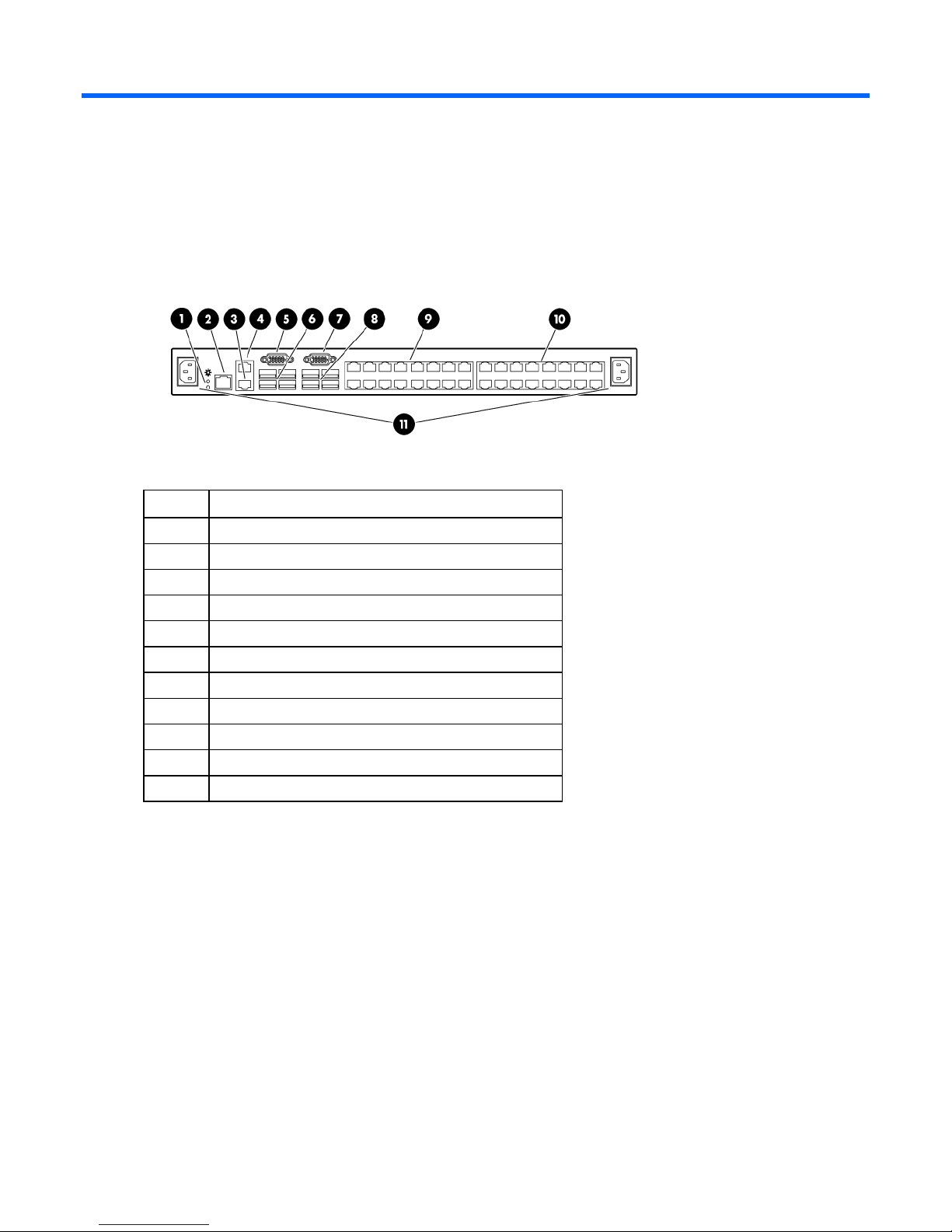
HP Server G2 Console Switch components
Item Description
1 Power supply status indicator LEDs
2 LAN connector
3 Tiering chain port
4 RJ-45 serial setup port
5 Console A VGA connector
6 Console A USB ports
7 Console B VGA connector
8 Console B USB ports
9 Interface adapter ports (1-16)
10 Interface adapter ports (17-32)
11 Power connectors A & B
Component identification 9
Page 10
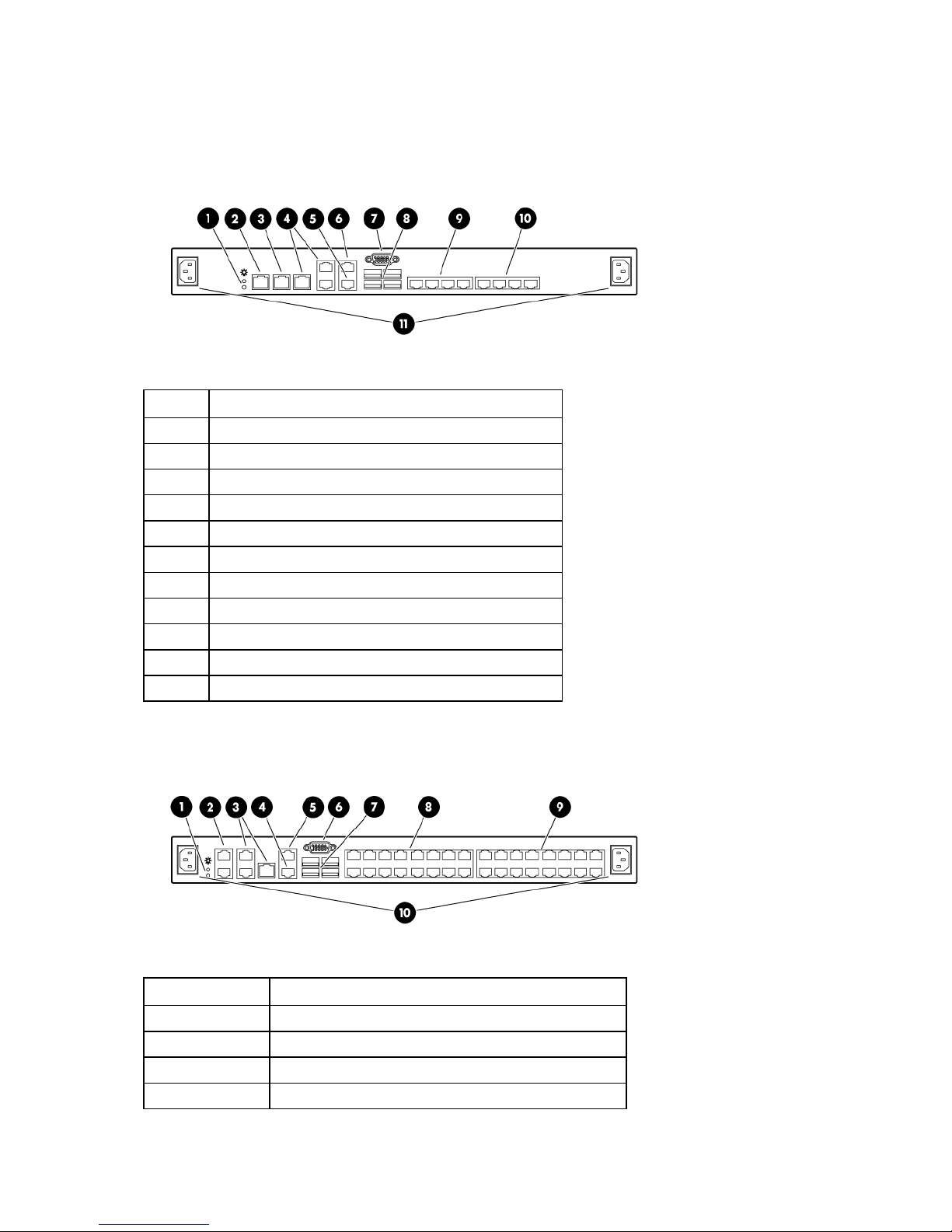
HP IP G2 Console Switch components
1x1Ex8
Item Description
1 Power supply status indicator LEDs
2 LAN 1
3 LAN 2
4 S1, S2, and S3 (reserved for future use)
5 Tiering chain port
6 RJ-45 serial setup port
7 Local console VGA
8 Local console USB ports
9 Interface adapter ports (1-4)
10 Interface adapter ports (5-8)
11 Power connectors A & B
2x1Ex16 or 4x1Ex32
Item Description
1 Power supply status indicator LEDs
2 LAN 1 and LAN 2
3 S1, S2, and S3 (reserved for future use)
4 Tiering chain port
Component identification 10
Page 11
Item Description
5 RJ-45 serial setup port
6 Local console VGA
7 Local console USB ports
8 Interface adapter ports (1-16)
9 Interface adapter ports (17-32)
10 Power connectors A & B
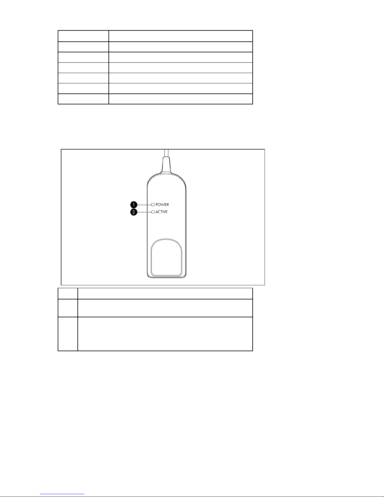
Interface adapters
Interface adapters that support Virtual Media have two LEDs on the front of the RJ-45 connector.
Item Description
1 When lit, this LED indicates that the interface adapter has power
from the server.
2 When lit, this LED indicates that there is an active console session
with the interface adapter.
When flashing, this LED indicates that the interface adapter
firmware is being upgraded.
Component identification 11
Page 12
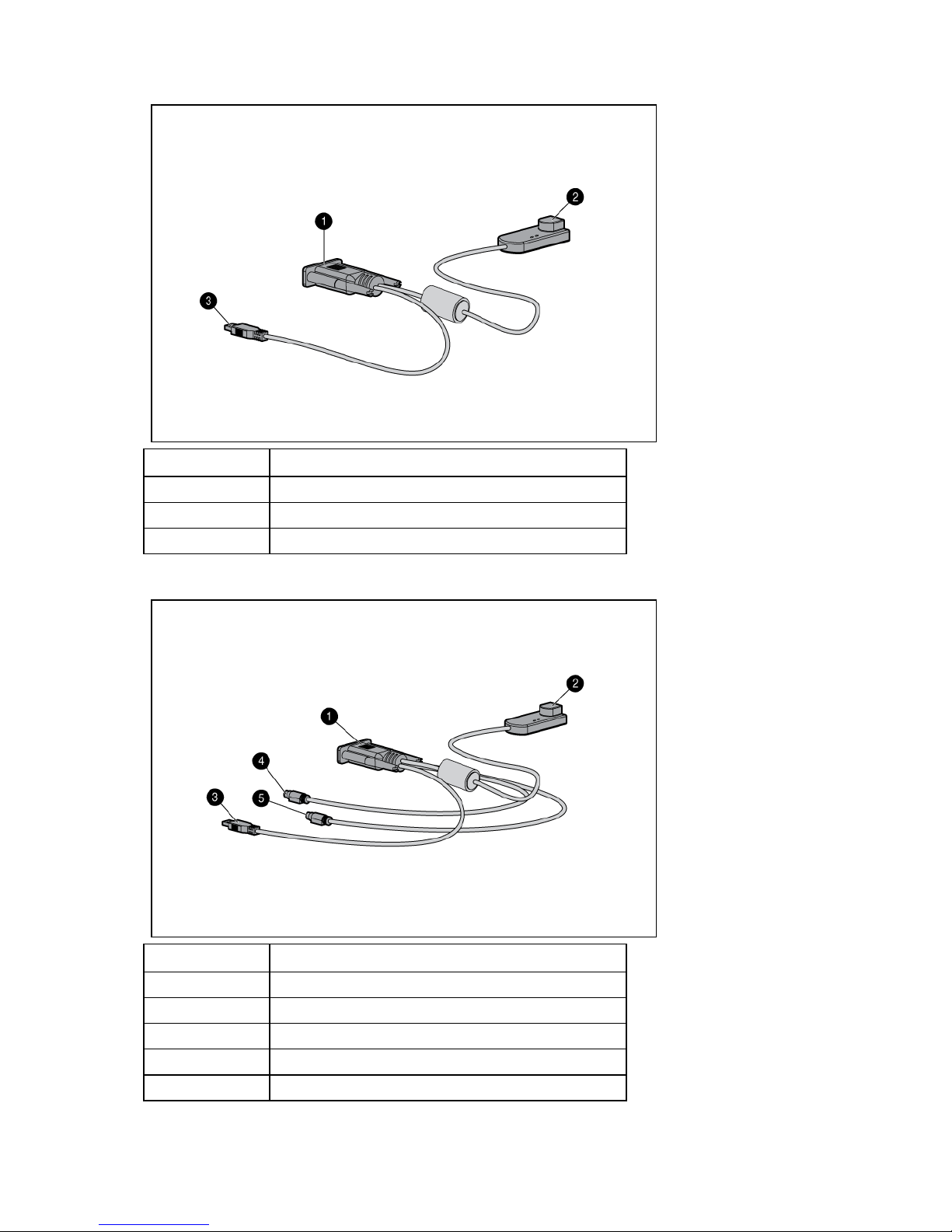
USB 2.0 interface adapter with Virtual Media
Item Description
1 Video connector
2 RJ-45 connector
3 USB connector
PS2 interface adapter with Virtual Media
Item Description
1 Video connector
2 RJ-45 connector
3 USB connector (for Virtual Media only)
4 Mouse connector
5 Keyboard connector
Component identification 12
Page 13
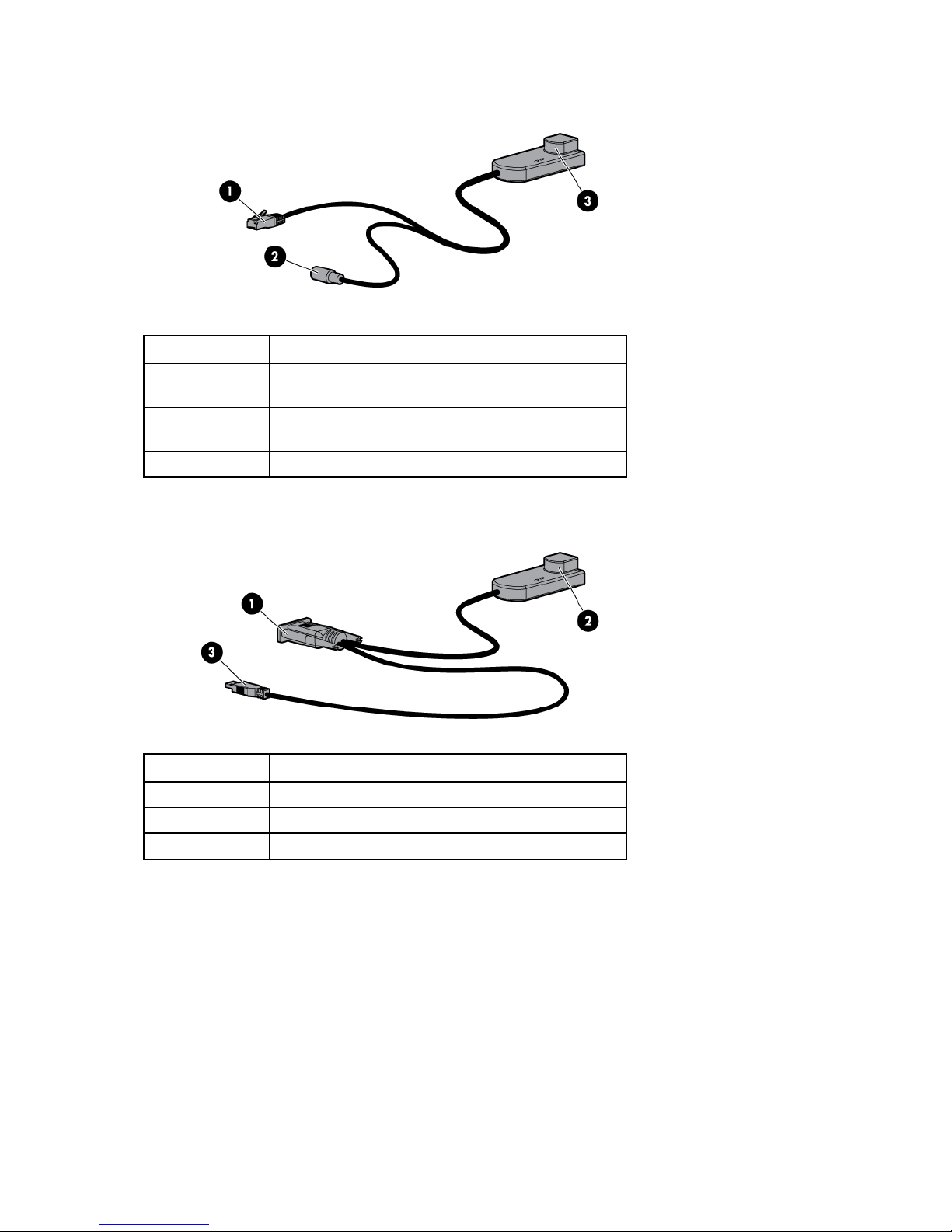
Serial interface adapter G2
Item Description
1 RJ-45 serial connector (to RJ-45/DB9 adapter or to a
Cisco appliance)
2 Power connector (mate to USB power connector or
power supply)
3 RJ-45 connector (for CAT5 to switch)
USB interface adapter with Virtual Media and CAC
Item Description
1 Video connector
2 RJ-45 connector
3 USB connector
Component identification 13
Page 14
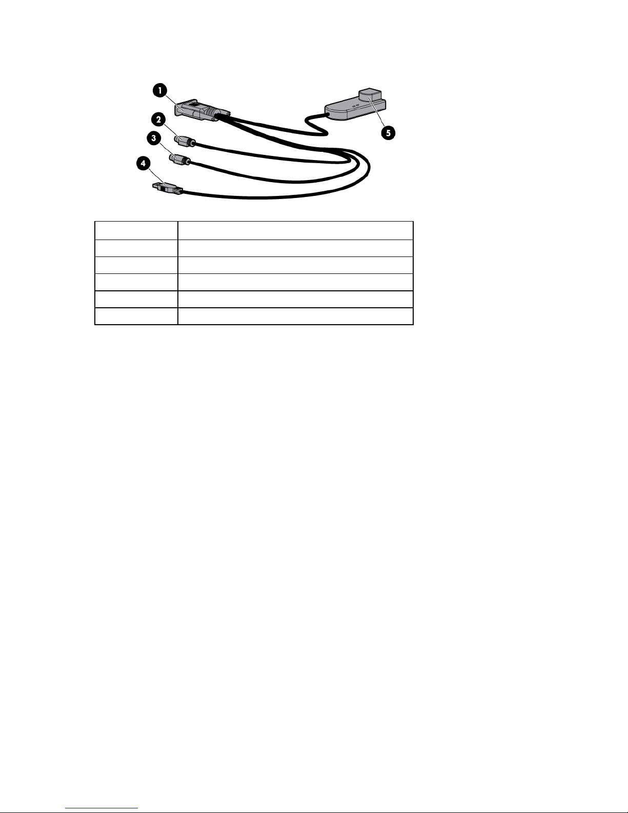
PS2 interface adapter with Virtual Media and CAC
Item Description
1 Video connector
2 Mouse connector
3 Keyboard connector
4 USB connector (for Virtual Media only)
5 RJ-45 connector
To determine which interface adapter you should use, see Selecting an interface adapter (on page 23).
Component identification 14
Page 15

Installing the console switch
Installation overview
This product ships with rack-mounting brackets for easy integration into the rack. Before installing this
product and other components in the rack cabinet (if they are not already installed), stabilize the rack in a
permanent location. Begin installing the equipment at the bottom of the rack cabinet, and then work to the
Rack-mount safety instructions
top. Avoid uneven loading or overloading of the rack cabinets.
When rack-mounting a console switch, consider the following factors:
• Elevated operating ambient temperature—If the equipment is installed in a closed or multi-unit rack
assembly, the operating ambient temperature of the rack environment might be greater than room
ambient temperature. Install the equipment in an environment compatible with the operating
temperature.
• Reduced air flow—In the rack, the rate of air flow required for safe operation of the equipment must
not be compromised.
• Mechanical loading—Avoid a potentially hazardous condition caused by uneven mechanical
loading by carefully mounting the equipment in the rack.
• Circuit overloading—When connecting the equipment to the supply circuit, consider the effect that
overloading of the circuits might have on overcurrent protection and supply wiring. Consider the
equipment nameplate ratings when addressing this concern.
• Reliable earthing—Maintain reliable earthing of rack-mounted equipment. Pay particular attention to
supply connections other than direct connections to the branch circuit, such as the use of power
strips.
Installation checklist
Console switch kit contents
Before installation, refer to the following lists to be sure that all of the listed components were received.
• Console switch
• Power cords
• Rack mounting kit
• CAT 5 serial adapter
• Documentation kit
This kit might contain extra hardware for your convenience.
Installing the console switch 15
Page 16

Required items not included
• Interface adapters ("Installing the interface adapter" on page 23)
One interface adapter is needed for each server or device.
o USB
o PS2
o Serial
o HP BladeSystem
• UTP CAT 5 or better cable
• Cage nuts and M6 screws (included with your original rack hardware kit)
Required tools
The following tools are required for some procedures:
• Phillips screwdriver
• Cage nut insertion tool (included with your original rack hardware kit)
Rack-mounting the console switch
WARNING: For safe use, do not mount this product with the rear panel, which is the side of
the console switch with I/O connectors and the AC power inlet, facing downward (facing the
1. Before installing the console switch into the rack, connect the console switch to a power source using
2. Choose one of the following configurations:
floor).
the power cords provided.
An activity indicator light is displayed after a few seconds. If the activity indicator light does not
display, be sure that the power cord is connected, and the power source is valid.
o Standard-mount
o Cantilever-mount
o Side-mount
Performing a standard-mount installation
1. Remove the six screws, three on each side, from the console switch.
Installing the console switch 16
Page 17

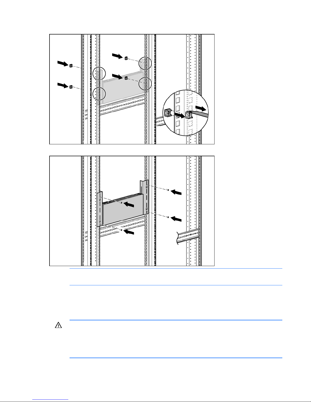
2.
Attach the long 1U brackets to the console switch using four of the screws you removed. Discard the
two remaining screws.
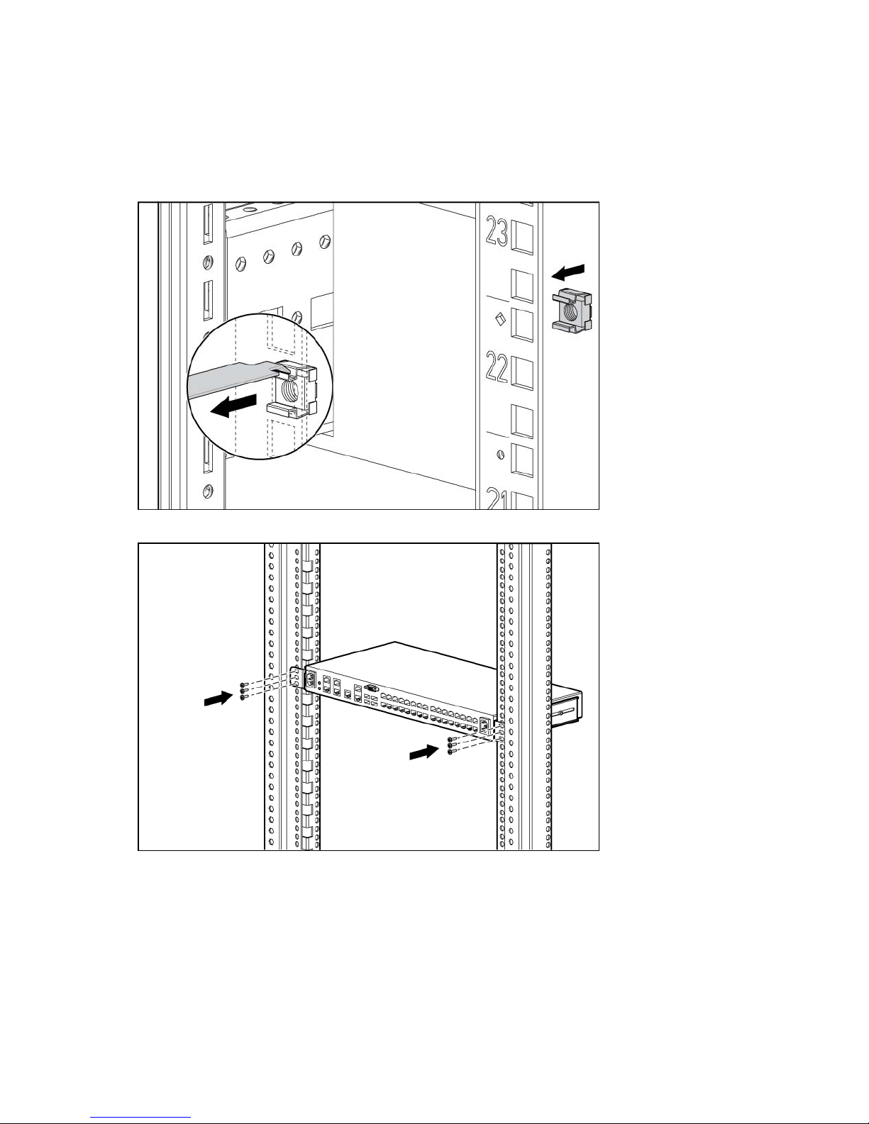
3. If not already installed, install a cage nut behind each rear rail.
4. Slide the console switch into the rear of the 1U product.
5. Secure the console switch to the rails using two M-6 screws, one on each side.
Installing the console switch 17
Page 18
Performing a cantilever-mount installation
1. Remove the six screws, three on each side, from the console switch.
2. Attach the long 1U brackets to the console switch using four of the screws you removed. Discard the
two remaining screws.
3. Install up to six cage nuts.
4. Secure the console switch to the rails using the appropriate number of M-6 screws.
Performing a side-mount installation
1. Remove the six screws, three on each side, from the console switch.
Installing the console switch 18
Page 19
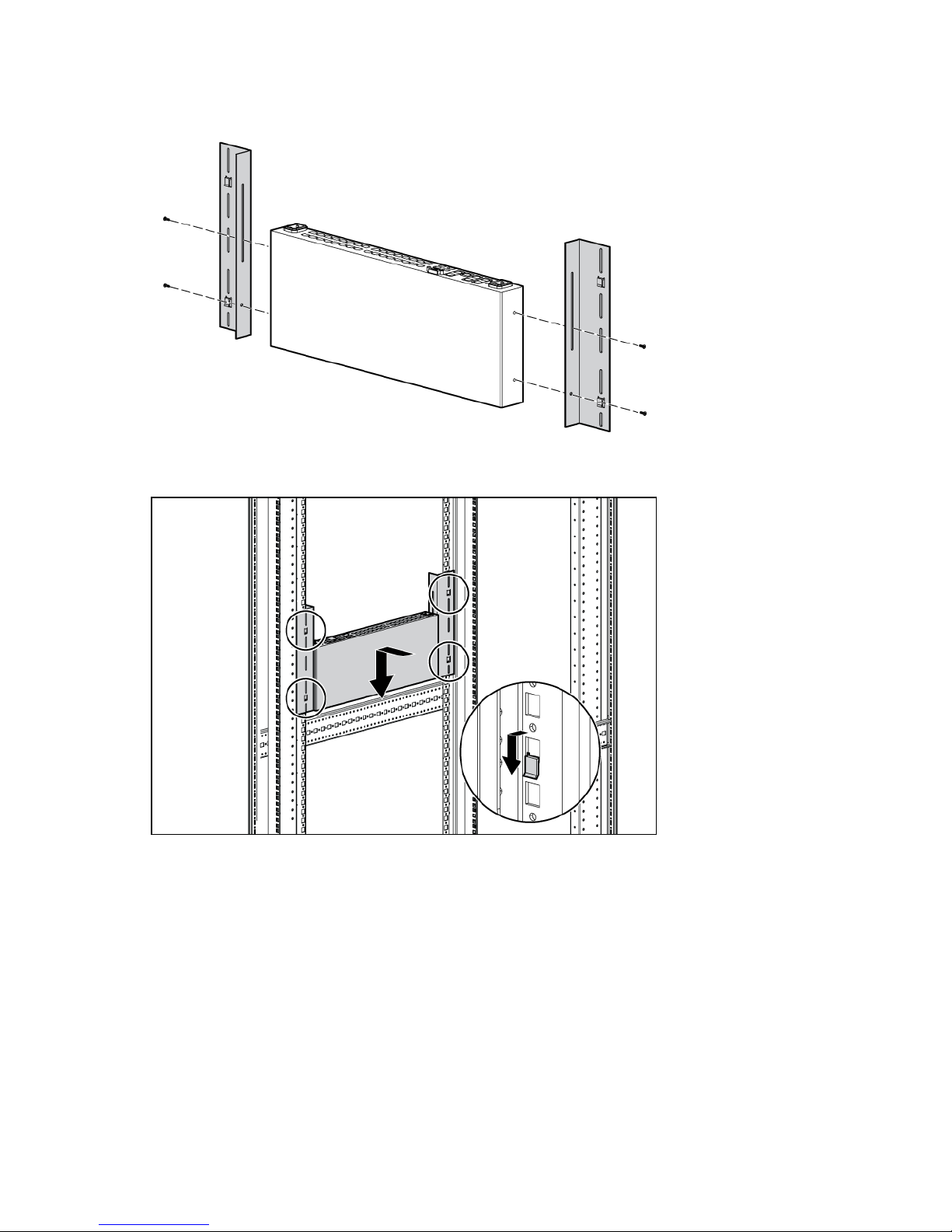
2.
Attach the side-mounting brackets to the console switch using four of the screws you removed.
Discard the two remaining screws.
3. Slide the side-mounting bracket tabs into the U locations on each side of the rack.
Installing the console switch 19
Page 20
4.
Install four cage nuts into the side-mounting bracket U locations.
5. Secure the console switch to the rails, using four M-6 screws, two on each side.
NOTE: Some racks enable you to use four sheet metal screws in place of M-6 screws and
cage nuts.
Connecting the console switch
1. Connect the local keyboard, video, and mouse to the console switch.
WARNING: To reduce the risk of electric shock or damage to the equipment:
• Do not disable the power cord grounding plug. The grounding plug is an important safety
feature.
• Plug the power cord into a grounded (earthed) electrical outlet that is easily accessible at
all times.
Installing the console switch 20
Page 21
• Unplug the power cord from the power supply to disconnect power to the equipment.
• Do not route the power cord where it can be walked on or pinched by items placed
against it. Pay particular attention to the plug, electrical outlet, and the point where the
2. Plug the console switch power cord into a power source. The power supply status indicator LED
illuminates.
cord extends from the storage system.
NOTE: UTP CAT5 cables are used throughout the examples in this guide. However, UTP
CAT5 or better cables can be used for any connection.
3. Connect a UTP CAT5 cable to the LAN connector on the console switch.
NOTE: For console switches that have 2 LAN connectors, you must connect them to 2
Ethernet switches on the same subnet.
4. Connect the other end of that same UTP CAT5 cable to an Ethernet switch.
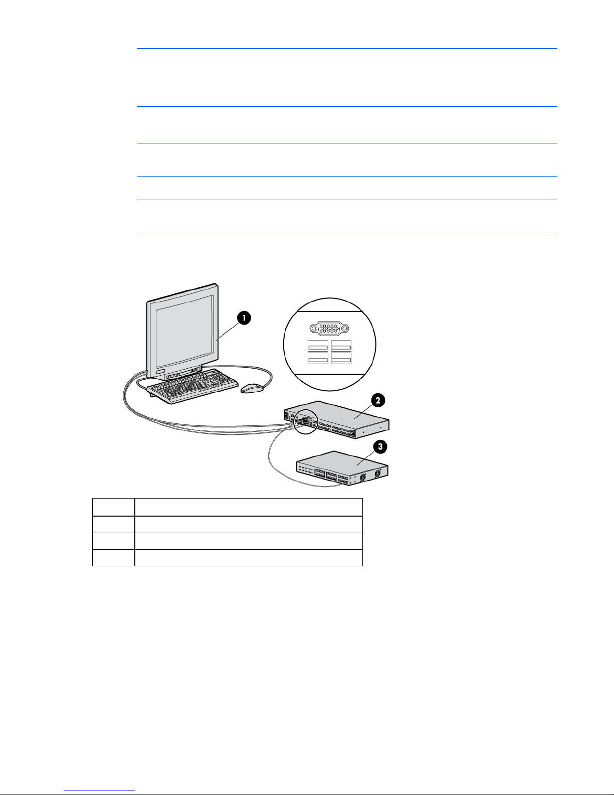
The following figure shows one possible configuration for your console switch system.
Item Description
1 Local console
2 Console switch
3 Ethernet switch
Verifying connections
Rear panel power status LEDs
The following LEDs illuminate to indicate connection status.
The rear panel features two power supply status indicator LEDs. The LEDs illuminate green in the following
patterns:
• Solid green—Both power supplies have power.
Installing the console switch 21
Page 22

• Blinks Morse code SOS—The power supply whose indicator LED is not blinking does not have
power or has failed.
• Blinks consistently—A firmware upgrade is in process.
Rear panel Ethernet connection LEDs
The rear panel of the switch features two LEDs that indicate the Ethernet connection for LAN1 and two
LEDs that indicate the Ethernet connection for LAN2.
The green LEDs illuminate when a valid connection to the network is established and blink when activity
occurs on the port.
The bi-color LEDs either illuminate green or amber.
• Green illumination—The communication speed is 1000 Mbps.
• Amber illumination—The communication speed is 100 Mbps.
• No illumination—The communication speed is 10 Mbps.
Virtual media and serial interface adapters LEDs
Typically, interface adapters feature two LEDs:
• Power LED—Illuminates green when the interface adapter is connected and receiving power.
• Active LED—Illuminates green when the interface adapter is in an active session.
• Active LED—Blinks green when the interface adapter firmware is flashed. Do not interrupt power to
the interface adapter during a firmware update.
HP IP Console Viewer overview
If you want the HP IP Console Viewer software to configure your console switch, you must install it. The HP
IP Console Viewer enables you to remotely organize and manage your local KVM and serial appliances,
as well as any device connected to them within your datacenter. For more information, see the HP IP
Console Viewer User Guide included on the CD provided with this product.
NOTE: The local console port does not require the HP IP Console Viewer software for
operation. The local console port uses the local console UI. For more information, see
The console switch system uses Ethernet networking infrastructures and the TCP/IP protocol to transmit
keyboard, video, and mouse information between operators and connected computers. Although 10BaseT Ethernet can be used, a dedicated, switched 100Base-T or 1000Base-T network provides improved
performance.
Configuring the console switch (on page 30).
Installing the console switch 22
Page 23

Installing the interface adapter
Interface adapter overview
An interface adapter is required for the console switch system to function properly. However, an interface
adapter is not included in the console switch kit. The interface adapter is connected to a console switch
using a CAT5 cable.
NOTE: UTP CAT5 cables are used throughout the examples in this guide. However, UTP
Selecting an interface adapter
There are several interface adapters available for use with the console switch. The following chart
describes the functionality and optimal uses for each adapter.
Interface
adapter
HP c-Class
Blade
HP PS2 PS2 262588-B21 KVM console access For servers that have PS/2
HP USB USB 336047-B21 KVM console access For servers that have USB
HP Serial Serial 373035-B21 Connecting to a serial
HP PS2
with Virtual
Media
HP USB
with Virtual
Media*
HP PS2
with Virtual
Media and
CAC
HP USB
with Virtual
Media and
CAC
HP Serial True AF625A Provides access to the serial For servers that require access to the
CAT5 or better cables can be used for any connection.
Type Part number Prime function Optimal use
Blade cClass
PS2M AF604A KVM and Hi-Speed Virtual
USB2 AF603A KVM and Hi-Speed Virtual
PS2MC AF624A Full-Speed Virtual Media
USBMC AF623A Full-Speed Virtual Media
AF605A Local console access to a
blade server
interface
Media (approximately 12x
CD-ROM) for servers with
PS/2 connectors
Media (approximately 12x
CD-ROM) for servers that do
not have PS/2 connectors
(approximately 6x CDROM) and CAC support for
servers with PS/2
connectors
(approximately 6x CDROM) and CAC support for
servers with USB connectors
For blade servers to connect to a
KVM for local access
connectors
connectors
For managing serial devices
through a serial interface
For servers that have PS/2
connectors and require Hi-Speed
Virtual Media
For servers that do not have PS/2
connectors, but require Hi-Speed
Virtual Media
For servers that have PS/2
connectors and require Full-Speed
Virtual Media and CAC support
For servers that have USB
connectors and require Full-Speed
Virtual Media and CAC support
serial console and all serial-
Installing the interface adapter 23
Page 24
Interface
Type Part number Prime function Optimal use
adapter
G2 serial console managed devices
*Not supported for use with ProLiant servers.
Connecting the interface adapter
NOTE: If you use the HP USB with Virtual Media interface adapter to connect to your ProLiant
server, test the functionality of your keyboard and mouse at the BIOS level before you load
1. Connect a UTP CAT5 cable to the interface adapter connection port on the console switch.
2. Connect the other end of that same UTP CAT5 cable to the RJ-45 connector on the interface adapter.
3. Connect the interface adapter to the appropriate connectors on the server.
4. Repeat steps 1 through 3 to connect any other servers or appliances to the console switch.
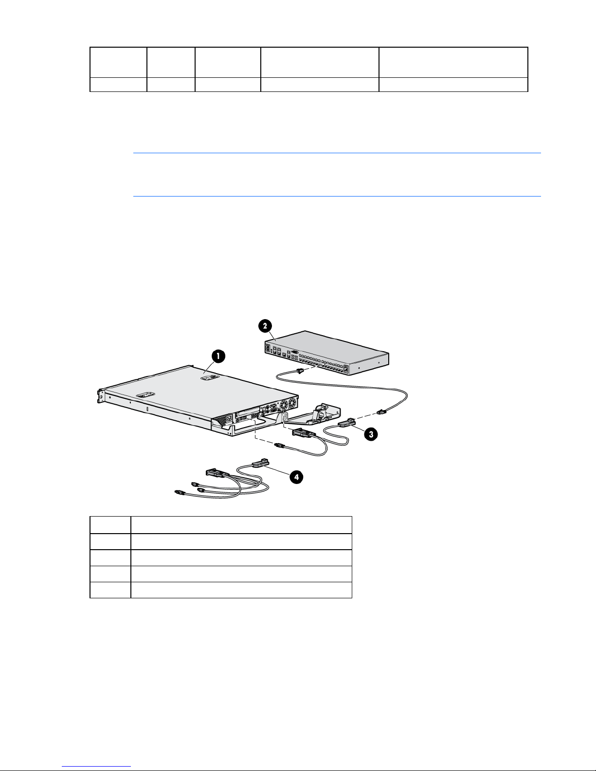
The following figure shows an example configuration for the console switch system with an interface
adapter.
your operating system.
Item Description
1 Server
2 Console switch
3 USB 2.0 interface adapter with Virtual Media
4 PS2 interface adapter with Virtual Media
Installing the interface adapter 24
Page 25

Cascading console switches
Cascading console switches overview
The G2 console switches support two levels of cascading or tiering devices. You can cascade multiple
console switches to increase the number of devices available from a single access point.
When cascading console switches with Virtual Media, verify the following:
• Interface adapters are not be used to cascade console switches. If interface adapters are used to
cascade console switches, you do not have seamless integration, and you lose Virtual Media
support. Use interface adapters with Virtual Media capability if you require Virtual Media.
• All cascaded console switches and interface adapters must have the most current firmware. To
Cascading console switches matrix
upgrade console switch firmware, see Upgrading the firmware (on page 72).
General rules of cascading console switches include:
• You can either cascade a newer console switch over an older console switch, or cascade switches of
the same generation. An older console switch cannot be the primary console switch over a newer
secondary switch.
• IP console switches cannot be cascaded under other IP console switches.
• In order for a particular feature to function, such as Virtual Media, all console switches and interface
adapters in the cascade must support the feature.
NOTE: The Virtual Media speed on an interface adapter that also supports smart cards is
only Full-Speed (approximately 6x CD-ROM). To use Hi-Speed Virtual Media (approximately
For configurations to work properly, you must have an interface adapter with Virtual Media connecting
each server to the console switch. For more information, see Using Virtual Media (on page 61).
HP Server Console Switches and Compaq Server Console Switches are not Virtual Media capable and
cannot be used as a primary console switch over any of the Virtual Media capable console switches.
The following table shows several two-level cascade configurations.
Primary console switch Secondary console switch Supported features*
HP IP Console Switch G2 with Virtual
Media
HP IP Console Switch G2 with Virtual
Media
HP IP Console Switch G2 with Virtual
Media
HP IP Console Switch G2 with Virtual
Media
12x CD-ROM), you must use a Virtual Media only interface adapter.
HP Server Console Switch G2 with
Virtual Media
HP Server Console Switch with Virtual
Media
HP Server Console Switch G2 KVM
HP Server Console Switch KVM
Virtual Media
Smart Card
Virtual Media
Cascading console switches 25
Page 26
Primary console switch Secondary console switch Supported features*
HP Server Console Switch G2 with
Virtual Media
HP Server Console Switch G2 with
Virtual Media
HP Server Console Switch G2 with
Virtual Media
HP Server Console Switch G2 with
Virtual Media
HP Server Console Switch G2 with
Virtual Media
*The listed supported features are only available if you cascade using an appropriate interface adapter that also
supports the listed feature. For example, if you want Virtual Media support, you must use an interface adapter that
supports Virtual Media.
HP IP Console Switch G2 with Virtual
Media
HP Server Console Switch G2 with
Virtual Media
HP Server Console Switch with Virtual
Virtual Media
Smart Card
Virtual Media
Smart Card
Virtual Media
Media
HP Server Console Switch G2 KVM
HP Server Console Switch KVM
Cascading two HP Server Console Switches G2
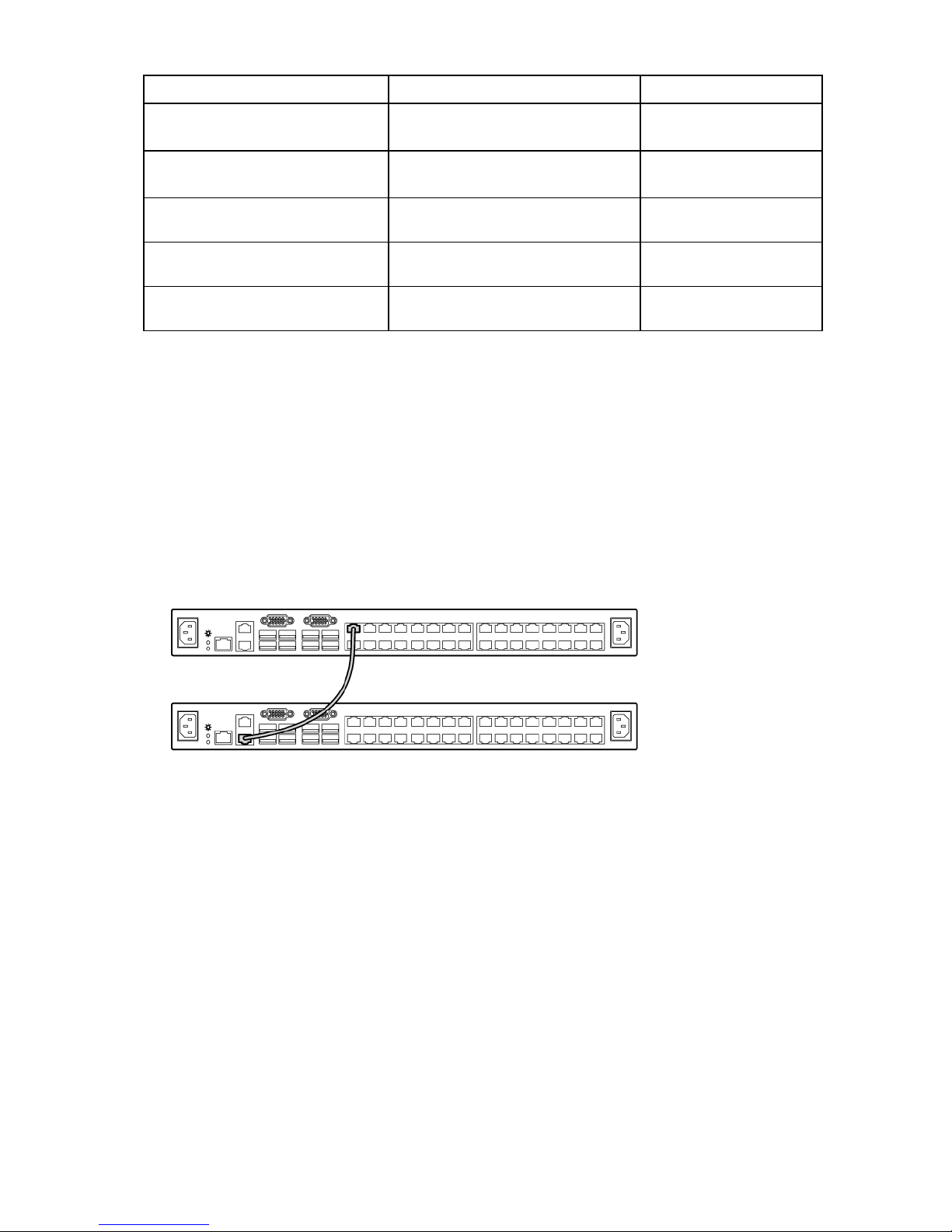
The following figure shows two HP Server Console Switches G2 cascaded together. The top console
switch is the primary console switch and the bottom console switch is the secondary console switch.
Do not use interface adapters to cascade console switches. If interface adapters are used to cascade
console switches, you do not have a seamless integration, and you lose Virtual Media support.
To cascade the console switches:
1. Connect a UTP CAT5 or better cable to the interface adapter port on the primary console switch.
2. Connect the other end of the cable to the tiering port on the secondary console switch.
Cascading console switches 26
Page 27
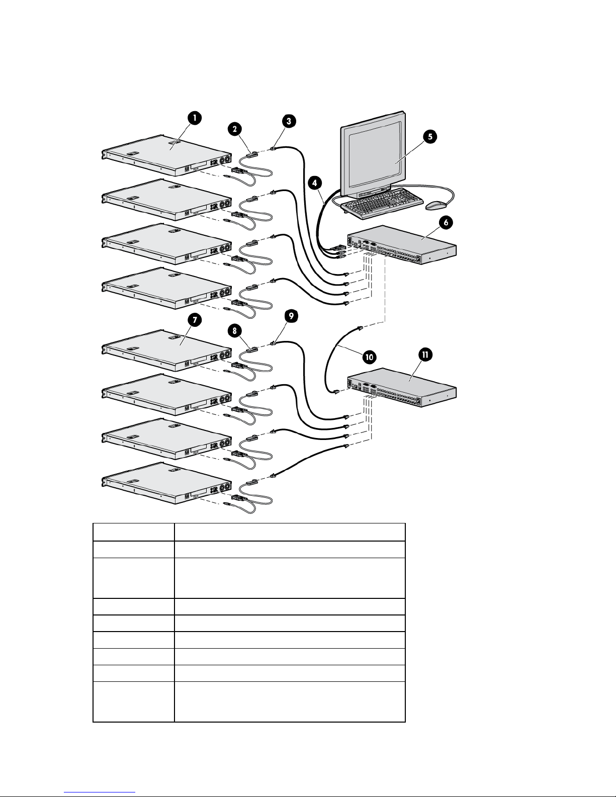
Example of an HP Server Console Switch G2 cascade
configuration
Item Description
1 Servers
2 Interface adapters (USB 2.0 interface adapter with
Virtual Media or PS2 interface adapter with Virtual
Media)
3 UTP CAT5 cable
4 Local console KVM cables
5 Local console monitor
6 Primary console switch
7 Servers
8 Interface adapters (USB 2.0 interface adapter with
Virtual Media or PS2 interface adapter with Virtual
Media)
Cascading console switches 27
Page 28

Item Description
9 UTP CAT5 cable
10 UTP CAT5 cable (tiering cable)
11 Secondary console switch
Cascading an HP Server Console Switch G2 under
an HP IP Console Switch G2
The following figure shows an HP Server Console Switch G2 cascaded to an HP IP Console Switch G2.
Do not use interface adapters to cascade console switches. If interface adapters are used to cascade
console switches, you do not have a seamless integration, and you lose Virtual Media support.
To cascade the console switches:
1. Connect a UTP CAT5 or better cable to the interface adapter port on the console switch.
2. Connect the other end of the cable to the tiering port on the secondary console switch.
Cascading an HP IP Console Switch G2 under an
HP Server Console Switch G2
The following figure shows an HP IP Console Switch G2 cascaded to an HP Server Console Switch G2.
Do not use interface adapters to cascade console switches. If interface adapters are used to cascade
console switches, you do not have a seamless integration, and you lose Virtual Media support.
Cascading console switches 28
Page 29

To cascade the console switches:
1. Connect a UTP CAT5 or better cable to the interface adapter port on the console switch.
2. Connect the other end of the cable to the tiering port on the secondary console switch.
Cascading console switches 29
Page 30

Configuring the console switch
The user interfaces
To configure and manage your console switch, you can use either the local console UI or the remote
OBWI.
The two user interfaces share a similar look and feel for optimal user experience. The information in this
chapter applies to both user interfaces.
From the interface, you can configure the console switch for your specific application, manage attached
devices, and handle all basic KVM or serial switching.
The following sessions are available from either interface:
• KVM—Enables you to control the keyboard, monitor, and mouse functions of individual target
devices that are connected to the switch during real-time operation. For more information, see the HP
IP Console Viewer User Guide.
• Serial—Enables you to manage individual target devices using the serial console.
Configuring the console switch using the local console UI
For detailed instructions on using the local console UI to configure the initial network setup, see Network
settings (on page 37).
To launch the local console UI interface:
NOTE: The HP IP and Server Console Switches G2 do not have PS/2 connectors for the
keyboard and mouse. You must use USB connections for your keyboard, mouse, media
1. Connect your keyboard, monitor, and mouse to the local port on the rear of the console switch. For
2. Select one of the keystrokes to launch the local console UI:
3. If local UI authentication is enabled, enter your username and password. The local console UI
devices, and smart card readers.
more information, see Connecting the console switch (on page 20).
NOTE: To change the keystrokes that launch the local console UI, see Local console UI
settings (on page 42).
o PrtSc
o Ctrl + Ctrl
interface opens.
4. Configure the network settings for either IPv4 or IPv6. For more information, see General network
settings (on page 37).
Configuring the console switch using the remote OBWI
The remote OBWI supports the following operating systems and browsers.
Configuring the console switch 30
Page 31

Operating system Browser:
Microsoft® Internet
Explorer® version 6.0
Browser:
Mozilla Firefox® version
2.0 and later
SP1 and later
Windows Server® 2003 Standard, Enterprise
of Web Edition
Windows XP Home Edition or Professional Yes Yes
Windows Vista® Yes Yes
Red Hat® Enterprise Linux 3, 4, and 5 No Yes
Sun® Solaris TM 9 and 10 No Yes
Novell® SUSE® Linux® Enterprise 9 and 10 No Yes
Fedora Core 6, 7, and 8 No Yes
Mac OS® X Tiger (10.4+) No Yes*
*Requires Firefox® 1.5 or later
Yes Yes
To log in to the remote OBWI:
1. Launch a web browser.
NOTE: If you are working in IPv6 mode, you must include square brackets around the IP
address.
2. In the address bar of the browser, enter the IP address or host name assigned to the switch you want
Example: https://[XXX.XX.XX.XX]
to access.
Examples: https://XXX.XX.XX.XX or https://hostname
NOTE: The default username is Admin with no password.
3. When the browser connects to the switch, enter your username and password.
4. Select Login. The remote OBWI appears.
Connecting to the remote OBWI through a firewall
Any console switch installation that uses the remote OBWI for outside access must have four ports opened
in a firewall.
TCP port number Function
22 Used by SSH during serial sessions to an MPUIQ-SRL
module
80 Used for the initial downloading of the Video Viewer
(for downloading the Java™ applet)
443 Used by the web browser interface for managing the
switch and launching KVM sessions
2068 Transmission of KVM session data or transmission of
video on switches
In some configurations, the workstation is located outside of the firewall and the console switch is inside
the firewall. To configure the firewall, forward ports 22, 80, 443, and 2068 from the external interface to
Configuring the console switch 31
Page 32

the KVM switch through the firewall internal interface. For specific port forwarding instructions, see your
firewall documentation.
Using the user interfaces
After you have successfully logged into either the local console UI or the remote OBWI, the user interface
appears.
Callout Component Description
1 Heading bar Displays the console switch you are
2 Side navigation
bar
3 Content area Displays the content for the category
Target devices
NOTE: The Target Devices page is the default view when you launch a console switch
The Target Device page enables you to view the name, type, and status of every interface adapter visible
to the console switch. If you are connected to an HP IP Console Switch, you can launch a session with an
interface adapter.
To view system information for the connected target devices:
session, using either the local console UI or the remote OBWI.
logged into
Displays system information, available
configuration and settings options, and
operations.
selected in the side navigation bar
1. Select Unit View>Target Devices. The Target Device page appears.
NOTE: HP recommends editing the interface adapter name so that it matches the name of the
device it is connected to.
Configuring the console switch 32
Page 33

2.
Select the name of the interface adapter you want to view. The Unit Overview page appears. The
following properties appear:
o Device name—Edit to match the name of the interface adapter it is connected to
o Type—Lists the type of interface adapter
o EID—Lists the identification number of the interface adapter
o Sessions—Enables you launch an interface adapter session
3. From the side navigation bar, select Connections to view the device connection path.
Appliance tools
Select Unit View>Appliance>Overview to view the name and type of console switch you are logged in to.
You can also perform basic appliance tasks, using the following tools:
• Reboot
• Upgrade Firmware ("Upgrading the console switch firmware" on page 34)
• Run Diagnostics
• Ping
• Save Appliance Configuration ("Saving the console switch configuration or user database" on page
35)
• Reset Appliance Configuration to Factory Defaults ("Restoring the console switch configuration or
user database" on page 35)
• Save Appliance User Database ("Saving the console switch configuration or user database" on
page 35)
• Restore Appliance User Database ("Restoring the console switch configuration or user database" on
page 35)
• Manage Appliance Web Certificate
Configuring the console switch 33
Page 34

• Save Application Trap MB
Upgrading the console switch firmware
HP recommends updating your console switch with the latest firmware available.
CAUTION: Do not disconnect an interface adapter during a firmware upgrade or power
cycling. The interface adapter becomes inoperable and must be returned to the factory for
After the Flash memory is reprogrammed with the upgrade, the console switch performs a soft reset,
terminating all interface adapter sessions. Any console switch receiving a firmware update might appear
disconnected or might not appear. The console switch appears again with a normal status once the Flash
update is complete.
To update the console switch firmware:
1. Select Unit View>Appliance>Overview. The Unit Overview page appears.
2. From the Tools list, select Upgrade Firmware.
repair.
NOTE: The Filesystem option is only available if you are logged in from the remote OBWI.
Configuring the console switch 34
Page 35

3.
Select one of the following options to load the firmware file:
o Filesystem—Select Browse to specify the location of the firmware upgrade file.
o TFTP—Enter the server IP address and firmware file to load.
o FTP—Enter the server IP address and firmware file to load. A username and password is required
for authentication.
o HTTP—Enter the server IP address and firmware file to load. A username and password is
required for authentication.
Saving the console switch configuration or user database
NOTE: To save or restore the console switch configuration or user database, you must be
logged in to the console switch from the remote OBWI.
You can save the configuration of a switch, the managed devices, and the local user database to a file.
By saving your configurations to a file, you can restore previous configurations to your console switch.
To save the console switch configuration or user database:
1. Select Unit View>Appliance>Overview. The Unit Overview page appears.
2. Select either Save Appliance Configuration or Save Appliance User Database. The Save Appliance
Configuration or Save Appliance User Database page appears.
3. Select the type and location where you want the file saved:
o Filesystem
o TFTP
o FTP
o HTTP PUT
4. Enter an Encryption Password.
Restoring the console switch configuration or user database
NOTE: To save or restore the console switch configuration or user database, you must be
To restore a previously saved console switch configuration or user database:
1. Select Unit View>Appliance>Overview. The Unit Overview page appears.
logged in to the console switch from the remote OBWI.
Configuring the console switch 35
Page 36

2.
Select either Restore Appliance Configuration or Restore Appliance User Database. The Restore
Appliance Configuration or Restore Appliance User Database page appears.
3. Select the type and location of the file you want to restore:
o Filesystem
o TFTP
o FTP
o HTTP
4. Enter the Decryption Password. The file is uploaded to the console switch.
5. Reboot the console switch ("Appliance tools" on page 33) to enable the restored configuration.
Viewing system information
1. Select Unit View>Appliance>Properties>Identity. The following properties appear:
o Part number
o Serial number
o EID
NOTE: HP recommends completing the Location information for the appliance, so that all
2. Select Unit View>Appliance>Properties>Location. The following properties appear:
3. Select Unit View>Appliance Settings>Versions to view the current firmware version. The current
appliances can be logically organized in the software.
o Site
o Department
o Location
firmware version is listed under the Application Version. The larger the version number, the more
current the firmware.
System alerts
In the top right-hand header of the interface, any current system alert appears.
The following alerts might appear:
• Power supply failure
• Elevated ambient temperature
• Fan failure
Configuring the console switch 36
Page 37

Network settings
Only Administrators can make changes to the network settings. All other users can view network settings,
General network settings
but cannot make changes.
To configure General network settings:
1. Select Unit View>Appliance>Appliance Settings>Network>General. The Appliance General Network
Settings page appears.
NOTE: If you change the LAN speed, you must reboot the console switch.
2. Configure the following parameters:
o LAN Speed
o ICMP Ping Reply
o HTTP Port
o HTTPS Port
3. Configure the network settings for either IPv4 or IPv6 mode. The default setting is IPv4 with BOOTP
enabled. The console switch is dual-stack capable, so both can be configured simultaneously.
DNS settings
To configure DNS settings:
1. Select Unit View>Appliance>Appliance Settings>DNS. The Appliance DNS Settings page appears.
Configuring the console switch 37
Page 38

2.
Select the DNS Assignment Mode:
o Manual
o BOOTP
o DHCPv6
3. Enter the DNS server addresses in the Primary, Secondary, and Tertiary fields.
NTP settings
To configure NTP settings:
1. Select Unit View>Appliance>Appliance Settings>NTP. The NTP page appears.
2. To enable NTP, select the Enable NTP checkbox.
3. Enter the name/address of the NTP servers in the NTP Server 1 and NTP Server 2 fields.
4. To enable the update interval, select the checkbox, and select the number of minutes for the update
interval.
SNMP settings
SNMP is a protocol used to communicate management information between network management
applications and the console switch. Other SNMP managers can communicate with your switch by
accessing MIB-II and the public portion of the enterprise MIB. You can designate which stations can
manage the switch as well as receive SNMP traps from the switch. If you enable SNMP, the console
switch responds to all SNMP requests over UDP port 161.
To configure your SNMP settings:
Configuring the console switch 38
Page 39

1.
Select Unit View>Appliance>Appliance Settings>SNMP. The SNMP page appears.
2. To enable SNMP, select the Enable SNMP checkbox.
3. Enter the appropriate information in the following fields:
o Name
o Description
o Contact
NOTE: The community name fields can be up to 64 characters in length. If SNMP is enabled,
these fields cannot be left blank.
4. Enter the Read, Write, and Trap community names to specify the community strings that must be
used in SNMP actions. These community names only apply to SNMP over UDP port 161, and they
act as a password to protect the console switch.
NOTE: To enable any workstation to manage the console switch, leave the Allowable
Managers fields blank.
5. In the Allowable Managers fields, enter the addresses of up to four workstations that are allowed to
manage this console switch.
Enabling SNMP traps
An SNMP trap is a notification sent by the console switch to a management station indicating that an
event has occurred in the switch that might require attention.
To enable individual SNMP traps:
Configuring the console switch 39
Page 40

1.
Select Unit View>Appliance>Appliance Settings>Auditing>Events. The Events page appears.
2. Select the checkbox for each SNMP trap you want sent to the management station.
3. Select Unit View>Appliance>Appliance Settings>Auditing>Destinations. The Event Destination page
appears.
Configuring the console switch 40
Page 41

Ports
4.
Enter up to four addresses of the management stations where you want the SNMP traps and Syslog
information sent.
You can view and edit the information for the following console switch ports:
• Interface adapters
• Cascade devices
• Local console port UI
Interface adapter ports
To view the port location of each interface adapter attached to the console switch:
Select Unit View>Appliance>Appliance Settings>Ports>IAs. The Appliance IAs page appears.
Deleting offline interface adapters
1. Select Unit View>Appliance>Appliance Settings>Ports>IAs. The Appliance IAs page appears.
2. Select Delete Offline.
Configuring interface adapter USB speed
NOTE: Configuring the interface adapter speed is only applicable to the HP USB with Virtual
Media Interface Adapter (AF603A) and the HP PS2 with Virtual Media Interface Adapter
1. Select Unit View>Appliance>Appliance Settings>Ports>IAs. The Appliance IAs page appears.
2. Select the checkbox next to the interface adapter you want to edit.
3. Select either Set USB 1.1 Speed or Set USB 2.0 Speed.
(AF604A).
Upgrading the interface adapter firmware
Interface adapters can be automatically updated when the console switch firmware is upgraded, if you
have Auto-Upgrade enabled. If issues occur during the normal upgrade procedure, interface adapters
might require a force upgrade.
To upgrade the interface adapter firmware:
Configuring the console switch 41
Page 42

1.
Select Unit View>Appliance>Appliance Settings>Ports>IAs. The Appliance IAs page appears.
2. Select the checkbox next to the interface adapter you want to upgrade.
3. Select Upgrade.
Interface adapter serial session settings
To configure the serial session settings of an individual interface adapter:
1. Select Unit View>Appliance>Appliance Settings>Ports>IAs. The Appliance IAs page appears.
2. Select the interface adapter you want to configure, by clicking the name under the EID column. The
IA page appears.
3. From the navigation tree on the left, select Settings. The IA Settings page appears.
4. Configure the following settings for the interface adapter:
o Baud Rate
o Data Bits
o Parity
o Stop Bits
o Flow Control
o DTR Mode
o Pinout
— If you are managing a Cisco device, select Cisco and connect the RJ-45 connector directly to
the management port of the appliance.
— If you are connecting to a DB9 Male DTE device, select ACS and connect the DB9 to RJ-45
adapter to the RJ-45 serial connector, and then connect it to the appliance.
Cascade devices ports
To view the port location of all cascaded appliances from the console switch:
Select Unit View>Appliance>Appliance Settings>Ports>Cascade Devices. The Appliance Cascade Devices
page appears.
You can edit the names of the cascaded devices by selecting the Name hyperlink.
Local console UI settings
Only the Administrator can make changes to the local port UI settings, such as:
• Enabling/Disabling local port user authentication, requiring users to log in to the interface.
• Select a User Access Level, determining what user level can disconnect another user's KVM or serial
session with a target device.
To configure local port UI settings:
Configuring the console switch 42
Page 43

1.
Select Unit View>Appliance>Appliance Settings>Ports>Local Port UI. The Local Port UI Settings page
appears.
2. In the Invoke Local Port UI, select the checkbox of one or more methods of launching a local console
UI session.
3. Configure the following parameters:
o Local port user settings
o Scan mode
o Keyboard
o Setup port settings
Configuring sessions
You can configure settings for the following session types:
• General
• KVM
• Virtual Media
Configuring General Session settings
• Serial
1. Select Unit View> Appliance> Appliance Settings> Sessions> General. The Appliance General
Session Settings page appears.
Configuring the console switch 43
Page 44

2. Configure the following parameters:
o In the Enable Inactivity Timeout checkbox, select or clear the checkbox.
o In the Inactivity Timeout field, select the number of minutes of inactive time you want to pass
before the session closes.
o In the Login Timeouts field, select the number of seconds of inactive time you want to allow
before failing an authentication request. For more information, see LDAP query (on page 52).
o In the Enable Preemption Timeout checkbox, select or clear the checkbox.
o In the Preemptive Timeout field, select the number of seconds you want to pass before the session
times out.
o In the Sharing field, select each checkbox you want to enable.
Configuring the console switch 44
Page 45

Configuring KVM Session settings
1. Select Unit View> Appliance> Appliance Settings> Sessions> KVM. The KVM Session Settings page
appears.
2. Configure the following parameters:
o Select an Encryption Level for your keyboard and mouse.
o Select an Encryption Level for your video.
o Select the language of the keyboard you are using.
o Select the monitor resolution you are using: either Standard or Widescreen. This resolution
becomes the default resolution for the local console.
Configuring Virtual Media Session settings
NOTE: You can disable the Virtual Media functionality on an individual interface adapter for
security purposes.
Configuring the console switch 45
Page 46

1.
Select Unit View> Appliance> Appliance Settings> Sessions> Virtual Media. The Appliance Virtual
Media Session Settings page appears.
2. Configure the Session Settings:
o Locked sessions—Locks the Virtual Media session to the KVM session. If you enable the Locked
session setting, your Virtual Media session is disconnected if the KVM session is disconnected.
o Reserved—Ensures that a Virtual Media connection can only be accessed by the user that
established the session. If you enable the Reserved setting, no other use can create a KVM
connection to that device.
3. Select the Virtual Media Access Mode:
o Read Only
o Read/ Write
4. Set the encryption level:
o None
o 128 bit
o DES
o 3DES
o AES
Configuring the console switch 46
Page 47

Configuring Serial Session settings
1. Select Unit View> Appliance> Appliance Settings> Sessions> Serial. The Appliance Serial Session
Settings page appears.
2. Select the Telnet Access Enabled checkbox, if you want to enable Telnet.
SSH communication is enabled by default. To connect to the console switch using SSH, you must
have a password assigned to the user account, as required by SSH.
Telnet is not a secure communication protocol. However, you can use any Telnet or SSH compliant
software, such as PuTTY or an OS command prompt to connect to the console switch. After
authentication, you are prompted for the name of the interface adapter you want to connect to.
User accounts
The local console UI and remote OBWI require login security through administrator-defined user accounts.
Administrators can add or delete users, as well as define users' preemption and access levels.
The following allowed operations are defined by user level:
Operation Access level:
Configure interface system-level
settings
Configure access rights Yes No
Add, change, and delete user Yes No
Access level:
Appliance
Users
Administrator
Yes No
Configuring the console switch 47
Page 48

Operation Access level:
accounts
Change your password Yes Yes
Access target device Yes Yes*
*Users can access a target device as long as the administrator has not reserved the device. For more information, see
Local virtual media settings.
Local user accounts
To configure local user accounts:
1. Select Unit View>Appliance>Appliance Settings>User Accounts>Local. The Appliance Local User
Accounts page appears.
2. Configure Security Lock-outs. If you enable security lock-outs, the lock-out is activated on the fifth
failed login attempt, per user account.
To add a user:
Appliance
Administrator
Access level:
Users
Configuring the console switch 48
Page 49

1.
Select Add. The Add Appliance Local User Account page appears.
2. Enter the Username and Password of the new user.
3. Select the Access Level.
4. Highlight all available target devices the user is assigned to, and then select Add.
To edit a user:
1. Select the checkbox next to the user you want to edit.
2. Select Edit, and then modify the user account.
To delete a user:
1. Select the checkbox next to the user you want to delete.
2. Select Delete.
MergePoint Access settings
To configure MergePoint Access settings:
Configuring the console switch 49
Page 50

1.
Select Unit View>Appliance>Appliance Settings>User Accounts>MergePoint Access. The Appliance
MergePoint Access Settings page appears.
2. Configure MergePoint Access settings.
Configuring LDAP
NOTE: Unless otherwise specified, use the LDAP default values, unless Active Directory has
been reconfigured. Modifying the default values might cause LDAP authentication server
You can configure the LDAP authentication priority and server connection information.
communication errors.
Configuring the console switch 50
Page 51

1.
Select Unit View>Appliance>Appliance Settings>User Accounts>LDAP. The Appliance LDAP
Overview page appears.
2. Configure the LDAP authentication priority by selecting either Use Local Authentication or Use LDAP
Authentication.
NOTE: The secondary LDAP server is optional.
3. Configure the LDAP servers information:
o Address—Specifies the host names or IP addresses of the primary and secondary LDAP servers.
o Port—Specifies the UDP port numbers that communicate with the LDAP servers. The default port
ID for non-secure LDAP is 389 and the default port ID for secure LDAPS is 636.
o Access Type—Specifies how a query is sent to each LDAP target device. When using LDAP, all
usernames, passwords, and other information sent between the LDAP server and the target
device are sent as non-secure clear text. Use LDAPS for secure encrypted communication.
For more information about LDAP configuration, see the HP IP Console Viewer User Guide.
LDAP search
To configure the parameters when searching for LDAP directory service users:
Configuring the console switch 51
Page 52

1.
Select Unit View>Appliance>Appliance Settings>User Accounts>LDAP>Search. The Appliance LDAP
Search page appears.
NOTE: The LDAP Search and Query parameters can only be configured if LDAP
2. Configure the Search parameters:
o Search DN—Defines the administrator-level user that the target device uses to log into the
directory service. Once the target device is authenticated, the directory service grants it access to
the directory to perform the user authentication queries specified on the LDAP query page. The
default values are cn=Administrator, cn=Users, dc=DomainName, and dc=com. Each search
value must be separated by a comma.
o Search Password—Used to authenticate the administrator or user specified in the Search DN
field.
o Search Base—Defines a starting point from which all LDAP searches begin. The default values
are dc=yourDomainName and dc=com. Each search value must be separated by a comma. For
example, to define a search base for test.com, your values are dc=test, dc=com.
o UID Mask—Specifies the search criteria for user ID searches of LDAP target devices. The format is
<name>=<%1>. The default value is sAMAccountName=%1, which corresponds to Active
Directory.
LDAP query
Authentication is enabled on the LDAP Overview ("Configuring LDAP" on page 50) page.
To configure LDAP query parameters:
Configuring the console switch 52
Page 53

1.
Select Unit View>Appliance>Appliance Settings>User Accounts>LDAP>Query. The Appliance LDAP
Query page appears.
NOTE: The LDAP Search and Query parameters can only be configured if LDAP
Authentication is enabled on the LDAP Overview ("Configuring LDAP" on page 50) page.
2. Configure the Query Mode parameters for:
o Appliance—Used to authenticate administrators and users attempting to access the console
switch itself.
o Target Device—Used to authenticate users attempting to access attached target devices.
There are three different modes available:
o Basic—A username and password query for the user is sent to the directory service. Once
verified, the user is given access to the appliance and any attached target devices.
o User Attribute—A username, password, and Access Control Attribute query for the user is sent to
the directory service. The Access Control Attribute is read from the user object in Active
Directory. If no values are found, the user is given no access to the appliance or target devices,
unless the user has User Admin privileges to the appliance.
o Group Attribute—A username, password, and group query sent to the directory service for an
appliance and attached target devices when using Appliance query mode or for a selected
target device when using Target Device query mode. If a group is found containing the user and
appliance name, the user is given access to either the appliance or target devices when using
Appliance query mode. If a group is found containing the user and target device IDs, the user is
given access to the selected target device when using Target Device query mode.
3. Configure the Group Configuration parameters:
Configuring the console switch 53
Page 54

o
Group Container—Specifies the OU created in Active Directory by the administrator as the
location for group objects. Group objects can contain users, computers, contacts, and other
groups, each assigned with a certain access level.
o Group Container Mask—Defines the object type of the Group Container, normally an OU. The
default value is ou=%1.
o Target Device Mask—Defines a search filter for the target device. The default value is cn=%1.
o Access Control Attribute—Specifies the name of the attribute used when the query modes are set
to User Attribute or Group Attribute. The default value is info.
Override admin
The Override Admin account is the administrative account built in to the console switch. It only
authenticates locally in the console switch.
Connections
To view all connections from the console switch, select Unit View>Appliance>Appliance
Settings>Connections. The Appliance Connections page appears.
Active sessions
To view a list of active sessions, select Unit View>Active Sessions. For each active session, the following
properties appear:
• Target device—The device in active session.
Configuring the console switch 54
Page 55

• Owner—The user logged in and activating the session.
• Remote host—The IP address of the computer where the active session is running.
• Duration—Amount of time the device has been in active session.
• Type—The type of session (KVM or Serial)
To launch a new active session:
NOTE: Java™ 1.5.0_11 or later is required to launch an active session when operating a
Linux or Mac operating system.
1. Select Unit View>Target Devices. A list of available devices appears.
2. On the Target Devices screen, under the Action column, select either KVM Session or Serial Session.
If the target device is currently in an active session, the user attempting to gain access can force a
connection to the device if the user's preemption level is equal to or higher than the current user's.
Local sessions
After you have established an active session, you can view the Local Session page from the local console
UI. The Local Session page only appears if there is an active session. The Local Session page provides the
following features:
• Connect Virtual Media
• Reset the USB interface
• Resume an active session
• Disconnect the active session
To launch a new active session at the local console and access the Local Session page:
1. Select one of the keystrokes to launch the local console UI:
o PrtSc
o Ctrl + Ctrl
The Local Session page appears.
2. Select Unit View>Target Devices. A list of available devices appears.
3. Select a different device and launch a KVM Session.
Scan mode
NOTE: Scan mode is only available when you are using the local console UI or the HP IP
In Scan mode, the console switch automatically scans from port to port (target device to target device).
You can scan multiple devices or specify exactly which devices to scan. The scanning order is determined
by the placement of target devices in the scanning list. You can also configure the time interval for the
scan.
Console Viewer software. If you are using remote OBWI, the Scan button is disabled.
To add target devices to the scan list:
1. Select Unit View>Target Devices. The Target Devices page appears.
2. Select the checkbox next to each device that you want to scan.
Configuring the console switch 55
Page 56

3.
Select Scan.
To configure the scan time interval, see Local console UI settings (on page 42).
Disconnecting an active session
1. Select Unit View>Active Sessions. The Appliance Sessions page appears.
2. Select the checkbox next to the target device session you want to close.
3. Select Disconnect.
Configuring the console switch 56
Page 57

Video Session Viewer
The Video Session Viewer overview
The Video Session Viewer is used to conduct a KVM session with target devices attached to a console
switch using the remote OBWI. When you connect to a target device using the Video Session Viewer, the
device desktop appears in a separate window containing both the local and target device cursors.
NOTE: Java™ 1.5.0_11 or later is required to launch an active session when operating a
The remote OBWI software uses a Java™-based program to display the video Viewer window. The
remote OBWI automatically downloads and installs the Video Session Viewer the first time it is opened.
The console switch does not install JRE, though it is available for download.
The remote OBWI uses system memory to store and display images within the Video Session Viewer
windows. Each opened Video Session Viewer window requires additional system memory:
Linux or Mac operating system.
• 8-bit color setting requires 1.4 MB of memory per window
• 16-bit color setting requires 2.4 MB of memory per window
• 32-bit color setting requires 6.8 MB of memory per window
HP recommends having no more than three simultaneous Video Session Viewer windows open. More
than four windows open simultaneously might affect system performance. You might receive an out-ofmemory error, and the requested Video Session Viewer window will not open.
If the target device you want to access is currently being viewed by another used, you are prompted to
preempt the other user if your preemption level is equal or greater than the other user's level. An
appliance administrator can disconnect an active user from the Active Session page of the remote OBWI.
Video Session Viewer 57
Page 58

The following view of the Video Session Viewer is in normal window mode.
Item Description
1 Title bar—Displays the name of the server you are
viewing
To access the menu bar, place your cursor in the middle
bottom of the title bar.
2 Menu bar—Enables you to access features
3 Server desktop—Enables you to interact with the server
through this desktop
4 Align Local Cursor icon—Enables you to reestablish
proper tracking of the local cursor to the remote server
cursor
5 Refresh Video icon—Enables you to regenerate the
digitized video image of the server desktop
6 Full Screen mode icon—Enables you to expand the
accessed server desktop to fill the entire screen
Video Session Viewer 58
Page 59

Changing the toolbar
You can adjust the amount of time that passes before the toolbar hides in the Video Session Viewer
window when it is not locked by thumbtack.
1. Choose one of the following options:
o From the Video Viewer window menu, select Tools>Session Options.
o Select the Session Options button.
The Session Options page appears.
2. Select the Toolbar tab.
3. Use the arrow keys to specify the number of minutes you want to pass before hiding the toolbar.
4. Select OK to save and close.
Launching a session
NOTE: If a user connects to a target device with a higher screen resolution than the local
computer, the Video Session Viewer window displays a portion of the target device screen,
with scroll bars for the remainder of the screen. The user can view the entire screen by
To launch a Video Session Viewer session from the remote OBWI, see Active sessions (on page 54).
adjusting the resolution on the target device, the local computer, or both.
Session time-out
A remote session might time-out when there is no activity in a session window within a specified time. The
session time-out value is configured through remote OBWI.
To enable, disable, or configure the time value for your session time-out, see Configuring General Session
settings (on page 43).
Adjusting the view
When using a non-proxied connection, video performance over a slower network connection might be
less than optimal. Certain color settings such as Grayscale use less network bandwidth than others, such
as Best Color. Therefore, adjusting the color setting can increase video performance.
To adjust the view of the Video Viewer, the following options are available:
• Align the mouse cursors.
• Refresh the screen.
• Enable or disable Full Screen mode. When Full Screen mode is enabled, the image adjusts to fit the
desktop up to a size of 1280 x 1024. If the desktop has a higher resolution, the full-screen image is
centered in the desktop and the areas around the Video Viewer are blank. The menu and toolbar
are locked to remain visible.
• Enable automatic, full, or manual scaling of the session image.
o Automatic scaling—The desktop window is sized to match the resolution of the target device
being viewed.
o Full scaling—The desktop window remains fixed and the device image scales to fit the window.
Video Session Viewer 59
Page 60

o
Manual scaling—A menu of supported image scaling resolutions appears.
• Change the color depth of the session image.
Window size
Each Video Viewer window can be set to a different resolution. The default resolution is 1024 x 768.
If autoscaling is enabled, the remote OBWI automatically adjusts the display if the window size changes
during a session. If the target device resolution changes during a session, the display automatically
adjusts.
To change the Video Viewer window resolution:
1. From the Video Viewer, select View>Scaling.
2. Select the desired resolution.
3. Select OK to save and close.
Video Session Viewer tasks
For a complete list of tasks and operations handled through the Video Session Viewer, see the "Managing
remote servers through the Video Session Viewer" section in the HP IP Console Viewer User Guide.
Closing a session
To close a Video Viewer session, select File>Exit.
Video Session Viewer 60
Page 61

Using Virtual Media
Virtual Media overview
In this section on Virtual Media, the remote console for HP Server Console Switches with Virtual Media is
only available if the console switch is tiered underneath an HP IP Console Switch with Virtual Media.
The console switch enables you to connect shared media to a server using a USB connection. This
capability enables you to manage systems more efficiently by performing operating system installation,
operating system recovery, program installation, file transfers, and BIOS updates from the local or remote
console.
You can connect Virtual Media directly to the console switch using one of the USB ports located on the
rear of the console switch. In addition, you can connect Virtual Media from any remote workstation that is
running the HP IP Console Viewer and is connected to a server using an HP IP Console Switch with Virtual
Media. All USB ports of a local console are assigned to a single Virtual Media session and cannot be
mapped independently to different servers.
To open a Virtual Media session with a server, you must first connect the server to the console switch
using an interface adapter with Virtual Media and establish a local console session.
Using a console switch with Virtual Media, you can map a removable mass storage device or a CD/DVD
type device on the console as a virtual drive on a target server. You can also add and map an .iso or
floppy image file on the local client as a virtual drive on the target server if you are using the HP IP
Console Viewer.
Limitations of using USB 2.0 composite devices with Virtual
Media
The default functionality for Virtual Media for a USB 2.0 interface adapter with Virtual Media capability is
the composite high-speed USB 2.0 capability of the USB protocol. The BIOS and particular operating
systems and installation programs of various target servers do not support composite USB 2.0 devices. If
your target server BIOS or operating system does not support such devices, then you must perform one of
the following actions:
• Purchase a PS2 interface adapter with Virtual Media and map a single Virtual Media device, which
operates in standard USB 2.0 mode.
• Disable the USB 2.0 function of the USB 2.0 interface adapter with Virtual Media from the console
switch local OSD, enabling the interface adapter to operate in USB 1.1 mode.
AMD Opteron™-based HP ProLiant servers and Red Hat Enterprise Linux 4 (before Update 5) do not
currently support composite USB 2.0 devices. However, the target server BIOS for Intel®-based HP
ProLiant G4 and later servers support composite USB 2.0 devices. If the server BIOS supports USB 2.0
composite devices, but the operating system installation program does not, a failure occurs when the
keyboard and mouse control is switched from the BIOS to the installation program.
Using Virtual Media 61
Page 62

HP recommends using the PS2 interface adapter with Virtual Media for AMD Opteron™-based HP
ProLiant servers and Red Hat Enterprise Linux 4 (before Update 5), as well as older and third-party
servers.
Virtual Media resources
Virtual Media resources cannot be shared between a local console and a remote console. For example, a
remote user using the HP IP Console Viewer cannot use a Virtual Media resource attached to the local
console USB hub. Only Virtual Media resources directly connected to the client's computer, running the
HP IP Console Viewer, can be mapped to a target server.
You can have one CD-type device and one mass-storage-type device mapped concurrently.
• A CD-type device includes a CD/DVD drive or an .iso image of a CD.
• A mass-storage-type device includes a floppy drive, floppy image file, USB memory device, or other
removable media type, such as an external USB hard drive.
Virtual Media requirements
In order for Virtual Media to work properly, the following requirements must be met:
• The target device must be connected to the console switch with an interface adapter, where both the
console switch and the interface adapter support virtual media.
• The target device must be able to use USB 2.0 compatible media that can be mapped virtually. If the
target device does not support a portable USB memory device, you cannot map the client server as
a virtual media drive on the target device.
• The user or user group must have permission to establish virtual media sessions to the target device.
• Only one virtual media session can be active on a target device at one time.
Configuring Virtual Media
Virtual Media is configured through the remote OBWI or the local console UI. For more information on
configuring virtual media, see Configuring Virtual Media Session settings (on page 45).
Sharing and preemption considerations
The KVM and virtual media sessions are separate, creating many options for sharing, reserving, and
preempting sessions.
The KVM and virtual media sessions might be locked together. In this mode, when a KVM session is
disconnected, so is the virtual media session. If the sessions are not locked together, the KVM session can
be closed, but the virtual media session might remain active. Use this option when you are performing a
time-intensive task using the virtual media session, such as loading an operating system, and want to
establish a KVM session with a different target device to perform other functions while the operating
system is loaded.
When a target device has an active virtual media session without an associated active KVM session,
either the original user (User A) can reconnect or a different user (User B) can connect to that channel.
You can set an option in the Virtual Media Session settings ("Configuring Virtual Media Session settings"
Using Virtual Media 62
Page 63

on page 45) to reserve sessions, allowing only User A to access that channel with a KVM session. By
using the reserved option in a tiered environment, only User A can access the lower switch and the KVM
channel between the upper switch and lower switch.
If User B is allowed to access the session, User B can control the media used in the virtual media session.
Virtual Media dialog box
The following options are available from the Virtual Media dialog box:
• You can manage the mapping and unmapping of virtual media. The dialog box displays all of the
physical drives on the client server that can be mapped as virtual drives. You can also add ISO and
floppy image files and then map to them using the Virtual Media dialog box. After a device is
mapped, the Virtual Media dialog box Details View displays information about the amount of data
transferred and the time elapsed since the device was mapped.
• You can reserve the virtual media session. When a session is reserved and the associated KVM
session is closed, another user cannot launch a KVM session to that target device. If a session is not
reserved, another KVM session can be launched.
• You can reset the USB 2.0 interface adapter. However, this action resets every form of USB media
on the target device. Use this option with caution, and only when the target device is not responsive.
Using Virtual Media through the Video Session
Viewer
You can launch a Virtual Media session and perform several tasks through the Video Session Viewer. For
more information, see the HP IP Console Viewer User Guide.
Using Virtual Media 63
Page 64

Using local Virtual Media
For local Virtual Media to work properly, you must have an HP Server Console Switch with Virtual Media
or an HP IP Console Switch with Virtual Media as the console switch. You must also have an interface
adapter with Virtual Media connecting each server to the console switch.
Item Description
1 Local user
2 USB media device
3 Console switch (HP Server Console Switch with Virtual
Media or HP IP Console Switch with Virtual Media)
4 USB 2.0 interface adapter with Virtual Media
5 PS2 interface adapter with Virtual Media
6 Server
Using Virtual Media in a two-level cascade
configuration
For Virtual Media to work properly in a two-level cascade configuration, you must have:
• A console switch with Virtual Media as the primary console switch
• A console switch with Virtual Media as the secondary console switch
• An interface adapter with Virtual Media connecting each server to the console switch
Using Virtual Media 64
Page 65

For more information on cascading, see Cascading console switches (on page 25).
Item Description
1 Local user
2 USB media device
3 Console switch (HP Server Console Switch with Virtual
Media or HP IP Console Switch with Virtual Media)
4 Secondary console switch (HP Server Console Switch
with Virtual Media)
5 USB 2.0 interface adapter with Virtual Media
6 PS2 interface adapter with Virtual Media
7 Server
Using Virtual Media 65
Page 66

Using smart cards
Smart card overview
You can use a smart card, also referred to as a CAC, with your console switch when two-factor
authentication is required.
NOTE: To use a smart card reader with a target device, you must first connect the target
You can connect smart card readers directly to the console switch using local USB ports, or you can
connect smart card readers to any remote workstation. The smart card reader must be connected prior to
starting a console session with the server. For more information about smart cards, see Using Smart Cards
(on page 66).
device to a console switch using a smart card capable interface adapter.
Using a smart card through Video Session Viewer
After you connect a smart card reader to an available USB port on the client server and are able to
access target devices, you can launch a KVM session to open the Video Session Viewer and map a smart
card.
The smart card status is indicated by the icon at the far right of the Video Session Viewer toolbar. One of
the following status icons appears.
Icon Description
A smart card is not in the smart card reader, or a smart card reader is not attached.
A smart card is in the smart card reader, but it has not been mapped.
A smart card is mapped.A smart card is mapped.
To map a smart card:
1. Launch a KVM session. The Video Session Viewer window appears.
2. Insert a smart card in to the smart card reader attached to your client server.
3. From the Video Session Viewer, select Tools>Map Smart Card.
4. Select your smart card, listed below the No Card Mapped option, to map the smart card.
To unmap a smart card you can:
• Close the KVM session by clicking the X in the Video Session Viewer window.
• From the Virtual Session Viewer, select Tools>No Card Mapped.
• Remove the smart card reader, or disconnect the smart card reader from the client server.
Using smart cards 66
Page 67

LDAP
LDAP overview
LDAP is a vendor-independent protocol standard used for accessing, querying, and updating a directory
using TCP/IP. Based on the X.500 Directory Services model, LDAP is a global directory structure that
supports strong security features, including authentication, privacy, and integrity.
If individual user accounts are stored on an LDAP-enabled directory service, such as Active Directory, you
can use the directory service to authenticate users. The default values given for the LDAP search and query
parameters are defined for use with Active Directory.
You can configure and define your authentication parameters through the remote OBWI. The software
sends the username, password, and other information to the target device, which then determines whether
the user has permission to view or change configuration parameters for the target device through the
remote OBWI.
LDAP configuration
LDAP authentication, search, and query parameters are configured through the remote OBWI. For more
information, see Configuring LDAP (on page 50).
Setting up Active Directory for performing queries
Before you can use any of the querying modes, you must update Active Directory so that the selected
querying mode can assign the applicable authorization level for the user.
To set up group queries:
1. Log in to Windows® with administrator privileges.
2. Open Active Directory software.
3. Create an organizational unit to be used as group container.
4. Create a computer object in Active Directory with a name identical to the switching system name for
querying appliances or identical to the attached target devices for querying target devices. The
name must match exactly and is case-sensitive.
5. The appliance names and target device names used for group queries are stored in the appliance.
The appliance name specified in the Appliance Overview screen of the remote OBWI and target
device names must be comprised of any combination of upper-case and lower-case letters, digits,
and hyphens, and must match the object names in Active Directory,
6. Create one or more groups under the group container organizational unit.
7. Add the usernames and the target device and appliance objects to the groups you created in step 5.
8. Specify the value of any attribute used to implement the Access Control Attribute.
LDAP 67
Page 68

Console switch serial management
Establishing LAN connections
NOTE: Although 10Base-T Ethernet can be used, HP recommends a dedicated, switched
100Base-T or 1000Base-T network for improved performance.
Connect the network cable from the LAN port on the rear panel of the console switch to an Ethernet
switch, and power on the console switch. For more information, see the HP IP Console Viewer User Guide
included on the CD provided with this kit.
Connecting to the serial management and setup port
Requirements:
• The G2 console switches use an RJ-45 serial port instead of the DB9 port. A DB9 DCE female to RJ-
45 serial adapter is included with the console switch.
• A UTP CAT5 or better cable, with standard CAT5 pinouts
To connect to the serial management and setup port:
1. Connect the DB9 adapter to an available COM port on the computer you will use to manage the
switch.
2. Connect the DB9 adapter to the console switch setup port, using a CAT5 or better UTP cable.
3. Configure the terminal emulation software, such as HyperTerminal ("Configuring HyperTerminal" on
page 68) or Minicom ("Configuring Minicom" on page 68).
4. Verify that the console switch is receiving power. After a few minutes, the console switch boots up.
5. Press the Enter key to access the Main Menu.
Configuring HyperTerminal
To configure the HyperTerminal:
1. From the desktop screen, select Start>Programs>Accessories>Communications>HyperTerminal. The
Connection Description window appears.
2. Enter a name for the description, and click OK. The Connect To window appears.
3. Select the Communication Port that is connected to the console switch through a serial cable, then
click OK. The COM1 Properties window appears.
4. Select 9600 for the Bits Per Second, 8 for Data Bits, None for Parity, 1 for Stop Bits, and None for
Flow Control, then click OK. The HyperTerminal auto-connects to the console switch.
5. Press the Enter key to access the console switch option menu.
Configuring Minicom
Console switch serial management 68
Page 69

NOTE: The following example uses Red Hat Linux 3.0. For more information, refer to your
Linux operating system Help or documentation.
IMPORTANT: Minicom is a utility that is loaded during the installation of Linux. However, if
you do not select the option to install the Linux Utilities during the operating system
installation, you cannot use Minicom without downloading the Minicom X.X.i386.rpm file
from the Red Hat website. (Refer to the procedure for installing RPMs on the Red Hat website.)
To configure Minicom:
1. Log in to a Linux console or open a terminal, and enter minicom-s at the command prompt. The
Configuration menu appears.
2. Select Serial Port Setup. The Change which setting? menu appears.
3. Select Option A (Serial Device). Manually change the device type from "dev/modem" to
"/dev/ttyS0" and press Enter.
4. Select Option E (Bps/Par/Bits). The Comm Parameters menu appears.
5. Select E (Speed 9600 Bps), and press Enter. The designation 9600 8N1 appears next to Option E.
6. Select Option F (Hardware Flow Control).
Be sure that the Change which setting? menu is configured as follows:
A—Serial Device: /dev/ttyS0
B—Lockfile Location: /var/lock
C—Callin Program:
D—Callout Program:
E—Bps/Par/Bits: 9600 8N1
F—Hardware Flow Control: No
G—Software Flow Control: No
7. Press the Enter key to return to the Configuration menu. Scroll down to the Save setup as dfl option,
and press the Enter key.
8. From the Configuration menu, scroll down to the Exit the Minicom option, and press Enter.
9. From the command prompt, enter Minicom. As soon as a connection is established, the main menu
for the console switch appears. Follow the on-screen options to configure the console switch. The
HyperTerminal menu appears.
Using the Main Menu
The following configuration options are available from the Console Switch Main Menu:
• Network configuration
• Enable debug messages
• Reset appliance
• Exit
Console switch serial management 69
Page 70

To access the Main Menu:
1. Establish a terminal session, and then press Enter. The Main Menu appears.
Network Configuration
The Network Configuration option enables you to set the network speed and either IPv4 or IPv6 settings.
Enable Debug Messages
The Enable Debug Messages option enables you to debug the system. Select yes to debug the system.
Reset Appliance
The Reset Appliance option reboots the server console switch.
Exit
The Exit option allows you to exit the Main Menu.
Console switch serial management 70
Page 71

Configuring the console switch NIC
1. Establish a terminal session and then press the Enter key. The Main Menu appears.
2. Select Option 1—Network Configuration. The Network Configuration Menu appears.
3. Select Option 1—Network Speed to set the network speed. When possible, set the connection
manually without relying on the auto negotiate feature. After you enter a selection, return to the
Network Configuration menu.
4. To specify an IPv4 or IPv6 IP address, select Option 2—IP Configuration, and then select the IP
address you option you want to configure. HP recommends using a static IP address for IPv4. The
console switch has Dual Stock capability.
5. If you are using a static IPv4 address, perform the following steps:
a. To specify an IP address, select Option 3—IP Address.
b. To specify a netmask, select Option 4—Netmask.
c. To specify a default gateway, select Option 5—Default Gateway.
When this configuration is complete, enter 0 to apply the changes and return to the Main Menu.
6. If you are using a static IPv6 address, perform the following steps:
a. To specify an IP address, select Option 3—IP Address.
b. To specify a prefix length, select Option 4—Prefix Length.
c. To specify a default gateway, select Option 5—Default Gateway.
When this configuration is complete, enter 0 to apply the changes and return to the Main Menu.
7. To exit to the Main Menu or to apply changes you made, select Option 0—Exit/Apply changes.
8. If you made any changes to the network speed you must reboot the console switch.
Recovering a lost console switch serial management
password
1. Establish a terminal session, and press the Enter key. You are prompted to enter the console switch
serial management password.
2. Enter HELP. A 16-bit key and the EID number of the console switch appear.
3. Call the HP technical support phone number (1-800-474-6836). Give the service person your 16-bit
key and EID number of the console switch. A one-time password, which is specific to your console
switch, is given to you.
4. Enter the one-time password. Your previous console switch serial management password is deleted.
For more information on recovering lost passwords through the local UI or remote OBWI, change the
Setup Port Settings through the Local console UI settings (on page 42).
Console switch serial management 71
Page 72

Upgrading the firmware
Upgrading the firmware
The console switch upgrade feature enables you to upgrade the console switch and interface adapters
with the latest available firmware through the local UI or remote OBWI. For more information, see
Upgrading the console switch firmware (on page 34) or Upgrading the interface adapter firmware (on
page 41).
Before beginning the upgrade procedure, be sure that the Secure TFTP Server is installed and that the GET
access permissions for the folder where the updated file is located are selected. Also, be sure that the
console switch is on the same network as the computer that is being used for the upgrade. After the TFTP
has been enabled, then upgrade the console switch firmware.
To enable TFTP for Microsoft® Windows®, see "Enabling TFTP for Microsoft Windows operating systems
(on page 72)."
To enable TFTP for Linux, see "Enabling TFTP for Linux operating systems (on page 72)."
Enabling TFTP for Microsoft Windows operating systems
To enable TFTP for Microsoft® Windows® operating systems, follow the instructions in the \TFTP\TFTP
Install Instructions.txt file on the CD included with this kit or the Softpaq TFTP directory.
Enabling TFTP for Linux operating systems
TFTP is provided by the TFTP server RPM (RPM-IVH/Redhat/RPMS/) for most systems using RPM
packages. Depending on the type of distribution, the Internet services daemon is provided by xinetd.
NOTE: The following example uses Red Hat Linux 3.0. For more information, refer to your
To enable TFTP for Linux operating systems (GNOME):
1. In the GNOME viewer go to the main menu and select Programs>System>Service Configuration.
2. In the Service Configuration menu, verify that the xinetd checkbox is selected to start at boot.
Linux operating system Help or documentation.
NOTE: By default, TFTP executes in secure mode and only provides readable files under the
/tftpboot directory. Other directories can be specified through the /etc/xinetd.d/tftp files. In
secure mode, TFTP expects the file to be relative to the/tftpboot directory.
-orIf the checkbox is not selected, select the box and click Save.
3. Find TFTP in the list of services and highlight it.
4. Select the checkbox to start TFTP at boot, and then click Save.
To enable TFTP for Linux operating systems (KDE):
1. Go to the main menu and select Control Panel>Services.
Upgrading the firmware 72
Page 73

2.
In the Service Configuration menu, verify that the xinetd checkbox is selected to start at boot.
-orIf the checkbox is not selected, select the box and click Save.
3. Find TFTP in the list of services and highlight it.
Verifying TFTP for Linux operating systems
4. Select the checkbox to start TFTP at boot, and then click Save.
NOTE: The following example uses Red Hat Linux 3.0. For more information, refer to your
Linux operating system Help or documentation.
1. Verify that the in.tftpd service is running with the following ps -ef | grep tftpd.
By default the /etc/xinetd.d/tftp configuration file uses /tftpboot as the directory.
2. Create a /tftpboot directory (if it doesn't exist) and set the permissions for public access.
3. Copy the firmware file to /tftpboot.
4. Cd to /tmp.
5. From the shell prompt, enter tftp localhost (or name of local system).
6. Download the file by entering the following command: get/tftpboot/filename
7. Enter quit.
8. From the shell prompt, check to see if the file is in the /tmp directory.
If the TFTP is configured correctly, the preceding steps transfer the file to the current directory.
Upgrading the firmware 73
Page 74

Troubleshooting
Console switch troubleshooting
Problem Troubleshooting
The console switch is
not working properly.
The console switch
hangs after reboot.
One of the power
supply status indicator
LEDs does not appear
and the other blinks
irregularly.
The system does not
recognize the
cascaded console
switches.
Servers are still listed
although they have
been disconnected.
The console switch
serial port password
is lost.
The video displays all
green or red, or the
colors are all wrong.
The mouse does not
align.
The mouse and
keyboard lose
functionality after the
Device Reset button is
pressed while
operating a UNIX®
based platform.
When connecting a
serial interface
adapter to a server
running Red Hat
Linux, SLES, or HPUX,
the numeric keypad
keys on a PC
keyboard do not map
to VT100 emulation
1 Determine whether the console switch has power.
2 Determine if all the cables are properly connected.
Reboot the console switch again by removing the power cable and then plugging it
back in to a power source.
One of the power supplies does not have power or is defective. The LED blinking
irregularly is blinking the Morse code SOS.
Verify that all of the console switches are HP switches, and are upgraded with the
latest firmware.
Delete the offline interface adapters ("Deleting offline interface adapters" on page
41) through either the local console UI or remote OBWI.
Reset the password through the Local console UI settings (on page 42).
• Look for breaks or bad crimps in the UTP CAT5 cable.
• Look for bent pins in the VGA connection.
• Be sure that the cable is not a cross-over network cable.
Verify that there is no mouse acceleration or enhanced pointed precision. The
mouse speed must be 50%.
The Device Reset button is a Microsoft® Windows® based function. To regain
mouse and keyboard functionality, restart the desktop.
Use the printenv command to show the TERM assigned under Linux. It can be
matched appropriately with other termcap entries by editing the profile or setting
the TERM equal to "ansi". For PC keyboards, ANSI is the most compatible
emulation.
-orEdit your /etc/inittab as s0:2345:respawn:/sbin/agetty -h ttyS0 115200, 9600
ansi
Where ttyS0 is the serial device name under Linux where the serial interface
Troubleshooting 74
Page 75

Problem Troubleshooting
under the Linux shell.
Using the numeric
keypad with the vi text
editor causes function
characters to appear
rather than numbers.
Virtual Media is not
working properly.
adapter is connected.
At a shell prompt, enter init q, or reboot the system.
Be sure that you are using the following:
• Console switches with Virtual Media
• A USB interface adapter with Virtual Media, or a PS2 interface adapter with
Virtual Media
• A server and operating system that supports high-speed composite USB 2.0
devices
You must be able to see a Virtual Media CD drive and a mass storage drive on the
target server to be able to map a local resource to the remote server.
Options in the Virtual
Media dialog box are
not available.
The keyboard does
not respond after
opening a Virtual
Media session.
The video resolution is
distorted.
See Configuring Virtual Media Session settings (on page 45).
See USB 2.0 composite device limitations.
See Connection length table (on page 75).
Connection length table
The console switch offers optimum video performance when the distance between the server and console
switch is 15 m (50 ft) or less. The system is capable of operation at distances up to 30.5 m (100 ft), at
reduced video resolutions.
Standard 4x3
Total cable
length
3 m (10 ft) X X X X
15 m (50 ft) X X X X
30.5 m (100 ft) — — — X
Widescreen 16x9 or 16x10
Total cable
length
3 m (10 ft) X X X X X
15 m (50 ft) X X X X X
30.5m (100 ft) — — — — X
1600 x 1200
@ 85 Hz
1680 x 1050
@ 60 Hz
1280 x 1024
@ 85 Hz
1440 x 900
@ 60 Hz
1024 x 768
@ 85 Hz
1280 x 800
@ 60 Hz
1024 x 640
@ 60 Hz
800 x 600
@ 85 Hz
800 x 500
@ 60 Hz
Troubleshooting 75
Page 76

Frequently asked questions
Console switch frequently asked questions
Question Answer
Are the interface adapters hot-pluggable? Yes, they are hot-pluggable to the console switch. Using
PS2 connections to servers might not be hot-pluggable.
Are the keyboard, monitor, and mouse
connections on the console switch hotpluggable?
Are the server connections on the console
switch hot-pluggable?
Can the console switch be mounted in a roundhole rack?
Can the console switch be side-mounted in a
round-hole rack?
How do I access the local console UI?
How do I cascade console switches? See Cascading console switches (on page 25).
How do I change the keyboard language? Language-specific keyboard emulation in the interface
How do I know which port my cascaded
console switch is connected to?
How do I locally connect a cascaded console
switch?
How do I view my console switch firmware
version?
How do I view my interface adapter firmware
version?
What kind of UTP cables are supported? Only UTP, CAT5, CAT5e, CAT6, and CAT7 cables are
Yes
Yes
Yes, the console switch can be mounted in a round-hole
rack using the standard-mount installation ("Performing a
standard-mount installation" on page 16).
No
• Press the Print Scrn key.
• Press the Ctrl key twice within one second.
adapter is determined by the keyboard language chosen
in the Local console UI settings (on page 42).
View the Port column of either the Interface adapter ports
(on page 41) or Cascade devices ports (on page 42).
Use a CAT5 or better cable to connect from an interface
adapter connection port on the primary console switch to
the tiering port on the secondary console switch.
See Viewing system information.
View the Application column of the Appliance IAs
("Interface adapter ports" on page 41) page.
supported.
Frequently asked questions 76
Page 77

Technical support
Before you contact HP
Be sure to have the following information available before you call HP:
• Technical support registration number (if applicable)
• Product serial number
• Product model name and number
• Product identification number
• Applicable error messages
• Add-on boards or hardware
• Third-party hardware or software
• Operating system type and revision level
HP contact information
For the name of the nearest HP authorized reseller:
• See the Contact HP worldwide (in English) webpage
(http://welcome.hp.com/country/us/en/wwcontact.html).
For HP technical support:
• In the United States, for contact options see the Contact HP United States webpage
(http://welcome.hp.com/country/us/en/contact_us.html). To contact HP by phone:
o Call 1-800-HP-INVENT (1-800-474-6836). This service is available 24 hours a day, 7 days a
week. For continuous quality improvement, calls may be recorded or monitored.
o If you have purchased a Care Pack (service upgrade), call 1-800-633-3600. For more
information about Care Packs, refer to the HP website (http://www.hp.com/hps).
• In other locations, see the Contact HP worldwide (in English) webpage
(http://welcome.hp.com/country/us/en/wwcontact.html).
Technical support 77
Page 78

Regulatory compliance notices
Regulatory compliance identification numbers
For the purpose of regulatory compliance certifications and identification, this product has been assigned
a unique regulatory model number. The regulatory model number can be found on the product nameplate
label, along with all required approval markings and information. When requesting compliance
information for this product, always refer to this regulatory model number. The regulatory model number is
Federal Communications Commission notice
not the marketing name or model number of the product.
This equipment has been tested and found to comply with the limits for a Class A digital device, pursuant
to Part 15 of the FCC Rules. These limits are designed to provide reasonable protection against harmful
interference when the equipment is operated in a commercial environment. This equipment generates,
uses, and can radiate radio frequency energy and, if not installed and used in accordance with the
instructions, may cause harmful interference to radio communications. Operation of this equipment in a
residential area is likely to cause harmful interference, in which case the user will be required to correct
the interference at personal expense.
FCC rating label
The FCC rating label on the device shows the classification (A or B) of the equipment. Class B devices
have an FCC logo or ID on the label. Class A devices do not have an FCC logo or ID on the label. After
you determine the class of the device, refer to the corresponding statement.
Class A equipment
This equipment has been tested and found to comply with the limits for a Class A digital device, pursuant
to Part 15 of the FCC Rules. These limits are designed to provide reasonable protection against harmful
interference when the equipment is operated in a commercial environment. This equipment generates,
uses, and can radiate radio frequency energy and, if not installed and used in accordance with the
instructions, may cause harmful interference to radio communications. Operation of this equipment in a
residential area is likely to cause harmful interference, in which case the user will be required to correct
the interference at personal expense.
Declaration of conformity for products marked with
the FCC logo, United States only
This device complies with Part 15 of the FCC Rules. Operation is subject to the following two conditions:
(1) this device may not cause harmful interference, and (2) this device must accept any interference
received, including interference that may cause undesired operation.
Regulatory compliance notices 78
Page 79

For questions regarding this product, contact us by mail or telephone:
• Hewlett-Packard Company
P. O. Box 692000, Mail Stop 530113
Houston, Texas 77269-2000
• 1-800-HP-INVENT (1-800-474-6836). (For continuous quality improvement, calls may be recorded
or monitored.)
For questions regarding this FCC declaration, contact us by mail or telephone:
• Hewlett-Packard Company
P. O. Box 692000, Mail Stop 510101
Houston, Texas 77269-2000
• 1281-514-3333
To identify this product, refer to the part, series, or model number found on the product.
Modifications
The FCC requires the user to be notified that any changes or modifications made to this device that are
not expressly approved by Hewlett-Packard Company may void the user’s authority to operate the
equipment.
Cables
Connections to this device must be made with shielded cables with metallic RFI/EMI connector hoods in
order to maintain compliance with FCC Rules and Regulations.
Canadian notice
This Class A digital apparatus meets all requirements of the Canadian Interference-Causing Equipment
Regulations.
Cet appareil numérique de la classe A respecte toutes les exigences du Règlement sur le matériel
brouilleur du Canada.
European Union regulatory notice
This product complies with the following EU Directives:
• Low Voltage Directive 2006/95/EC
• EMC Directive 2004/108/EC
• Machinery Directive 98/37/EEC
Compliance with these directives implies conformity to applicable harmonized European standards
(European Norms) which are listed on the EU Declaration of Conformity issued by Hewlett-Packard for this
product or product family.
This compliance is indicated by the following conformity marking placed on the product:
Regulatory compliance notices 79
Page 80

This marking is valid for non-Telecom products and EU harmonized Telecom products (e.g. Bluetooth).
This marking is valid for EU non-harmonized Telecom products.
*Notified body number (used only if applicable—refer to the product label)
Hewlett-Packard GmbH, HQ-TRE, Herrenberger Strasse 140, 71034 Boeblingen, Germany
The official EU CE declaration of conformity for this device can be found on the HP website
(http://www.hp.com/go/certificates).
Disposal of waste equipment by users in private
households in the European Union
This symbol on the product or on its packaging indicates that this product must not be
disposed of with your other household waste. Instead, it is your responsibility to dispose of
your waste equipment by handing it over to a designated collection point for the recycling of
waste electrical and electronic equipment. The separate collection and recycling of your
waste equipment at the time of disposal will help to conserve natural resources and ensure
that it is recycled in a manner that protects human health and the environment. For more
information about where you can drop off your waste equipment for recycling, please contact
your local city office, your household waste disposal service or the shop where you
purchased the product.
Regulatory compliance notices 80
Page 81

Japanese notice
Korean class A notice
Power cord statement for Japan
Regulatory compliance notices 81
Page 82

Acronyms and abbreviations
AC
alternating current
BIOS
Basic Input/Output System
BOOTP
Bootstrap Protocol
CAC
Common Access Card
CRC
cyclic redundant checks
EID
electronic identification number
FTP
file transfer protocol
G2
Generation 2
GNOME
GNU Network Object Model Environment
HP SIM
HP Systems Insight Manager
IA
interface adapter
ID
identification
Acronyms and abbreviations 82
Page 83

IP
Internet Protocol
KVM
keyboard, video, and mouse
LAN
local-area network
LDAP
Lightweight Directory Access Protocol
LED
light-emitting diode
NIC
network interface controller
OBWI
on-board Web interface
OSD
on-screen display
PCI
peripheral component interface
RPM
Red Hat Package Manager
SIM
Systems Insight Manager
SLES
SUSE Linux Enterprise Server
SSH
Secure Shell
TCP
Transmission Control Protocol
Acronyms and abbreviations 83
Page 84

TFTP
Trivial File Transfer Protocol
UI
user interface
USB
universal serial bus
UTP
unshielded twisted pair
VGA
video graphics array
Acronyms and abbreviations 84
Page 85

Index
A
activating Scan mode 55
Active session, disconnecting 56
Active sessions 54
alerts 36
appliance connections 54
appliance tools 33
appliance, reset 70
authorized reseller 77
console switch, configuration 30
console switch, connecting 20
console switch, installing 15
console switch, rack mounting 15
console switch, serial management 68
console switch, side-mount 18
console switch, standard mount 16
console switches, cascading 25
contacting HP 77
D
B
buttons 9
C
cables 79
Canadian notices 79
cantilever mount 18
cascaded console switch configurations 26, 27, 28
cascading console switches 25
cascading console switches matrix 25
cascading console switches, overview 25
class A equipment 78
components 9
components, identification 9, 10, 11
composite device limitations, USB 2.0 61
configuration, restoring 35
configuration, saving 35
configuring Minicom 68
configuring session options 43
configuring the console switch 30
configuring the console switch NIC 71
configuring, local console UI 30
configuring, remote OBWI 30
connecting, console switch 20
connecting, interface adapter 24
connection length 75
connection problems 31
connections, appliance 54
connections, verfiying 21
connectors 9
console switch serial management 68
console switch, canti-lever mount 18
debug messages, enable 70
Declaration of Conformity 78
disconnecting an active session 56
DNS settings 37
E
enabling TFTP 72
establishing, LAN connections 68
European Union notice 79
F
FCC rating label 78
features 7, 9
Federal Communications Commission (FCC)
notice 78, 79
firewall settings, configuring 31
firmware, upgrading 72
firmware, upgrading console switch 34
frequently asked questions 76
G
General network settings 37
H
HP IP Console Viewer 22
HP technical support 77
HyperTerminal, configuring 68
I
installation checklist 15
Index 85
Page 86

installation overview 15
installation, cantilever mount 18
installation, side mount 18
installation, standard-mount 16
installing the console switch 15
installing the interface adapter 23
interface adapter 23
interface adapter ports 41, 42
interface adapter, components 11
interface adapter, connecting 24
interface adapter, deleting 41
interface adapter, displaying status information 41
interface adapter, installing 23
interface adapter, overview 23
interface adapter, selecting 23
interface adapter, upgrading firmware 41
interface adapter, USB speed 41
interface adpater, LEDs 22
interface, browser 30
IP console switch components 10
J
Japanese notice 81
modifications, FCC notice 79
N
network settings 37
network settings, DNS 37
network settings, general 37
network settings, NTP 38
network settings, SNMP 38
NTP settings 38
O
Override Admin 54
overview of installation process 15
P
phone numbers 77
ports 41
ports, cascade devices 42
ports, interface adapter 41
power cord 81
preemption and sharing 62
product features 7
K
kit contents 15
Korean notices 81
KVM switching capabilities 7
L
LAN connections, establishing 68
LDAP, Active Directory 67
LDAP, configuration 50, 67
LDAP, overview 67
LDAP, query modes 52, 67
LDAP, search 51
LED, console switch 21, 22
LED, interface adapter 22
LEDs 9
Linux, enabling TFTP 72
Linux, verifying TFTP 73
local console UI 30
local console UI, settings 42
M
Main Menu, Exit 70
MergePoint Access 49
Minicom, configuring 68
R
rack mounting, console switch 16
rack-mount safety 15
rack-mounting configurations 16
rear panel LEDs 21, 22
regulatory compliance identification numbers 78
regulatory compliance notices 78, 80
remote OBWI 30
required information 77
required items not included 16
required tools 16
S
safety considerations 15
Scan mode, activating 55
selecting an interface adapter 23
serial interface adapter 42
serial management port, connecting 68
serial management, console switch 68
serial management, enable debug messages 70
serial management, exit 70
serial management, Main Menu 69
serial management, network configuration 70
serial management, recovering lost console switch
password 71
Index 86
Page 87

serial management, reset appliance 70
server console switch components 9
session settings, General 43
session settings, KVM 45
session settings, serial 47
session settings, virtual media 45
sharing and preemptions 62
side-mount 18
smart card 8
smart cards, overview 66
SNMP settings 38
SNMP traps 39
SNMP traps, enabling 39
standard-mount (1U) 16
support 77
switching capabilities 7
system alerts 36
T
technical support 77
telephone numbers 77
TFTP, enabling for Windows 72
TFTP, Linux operating systems 72
TFTP, verifying for Linux 73
tools, appliance 33
troubleshooting 74
true serial 8
Video Session Viewer, overview 57
Video Session Viewer, session time-out 59
Video Session Viewer, smart cards 66
Video Session Viewer, tasks 60
Video Session Viewer, toolbar 59
Video Session Viewer, Virtual Media 63
viewing system information 36
Virtual Media 8, 61
Virtual Media parameters, configuring 62
Virtual Media, dialog box 63
Virtual Media, local 64
Virtual Media, overview 61
Virtual Media, requirements 62
Virtual Media, resources 62
Virtual Media, using 61
W
Windows, enabling TFTP 72
U
upgrade firmware 72
upgrading console switch firmware 34
upgrading interface adapter firmware 41
USB 2.0 composite device limitations 61
user accounts 47
user accounts, local 48
user database, restoring 35
user database, saving 35
user interfaces 8, 30, 32
using, local Virtual Media 64
using, Virtual Media in a two-level cascade
configuration 64
V
verifying connections 21
versions, displaying 36
Video Session Viewer 57
Video Session Viewer, adjusting 59, 60
Video Session Viewer, closing a session 60
Video Session Viewer, launching a session 59
Index 87
 Loading...