

Page 1

HP Intelligent Management Center — MVM
User Guide
Abstract
This guide contains basic information for network administrators, engineers, and operators who use the MVM product.
HP Part Number: 5998-3962
Edition: 1
Page 2

© Copyright 2012, 2012 Hewlett-Packard Development Company, L.P.
Confidential computer software. Valid license from HP required for possession, use or copying. Consistent with FAR 12.211 and 12.212, Commercial
Computer Software, Computer Software Documentation, and Technical Data for Commercial Items are licensed to the U.S. Government under
vendor's standard commercial license.
The information contained herein is subject to change without notice. The only warranties for HP products and services are set forth in the express
warranty statements accompanying such products and services. Nothing herein should be construed as constituting an additional warranty. HP shall
not be liable for technical or editorial errors or omissions contained herein.
Acknowledgements
Microsoft®, Windows®, Windows® XP, Windows NT, ® and SQL Server® are U.S. registered trademarks of Microsoft Corporation.
Adobe® and Acrobat® are trademarks of Adobe Systems Incorporated.
MySQL® and Oracle® are registered trademarks of Oracle and/or its affiliates.
UNIX® is a registered trademark of The Open Group.
Warranty
WARRANTY STATEMENT: To obtain a copy of the warranty for this product, see the warranty information website:
http://www.hp.com/go/storagewarranty
Revision History
Revision History
31 October 2012Revision #1
First draft of document
Printed in the US
Page 3

Contents
1 MVM Introduction.......................................................................................7
2 L2VPN Manager........................................................................................8
L2VPN Manager Overview........................................................................................................8
Usage Summary.....................................................................................................................11
Typical Applications................................................................................................................12
VPLS Instance Configuration................................................................................................12
VLL Instance Configuration..................................................................................................14
PBB Instance Configuration.................................................................................................15
Using L2VPN Manager...........................................................................................................17
VPN devices.....................................................................................................................17
PE devices....................................................................................................................17
Import PE................................................................................................................18
Query PE................................................................................................................18
Delete PE.................................................................................................................18
Synchronize PEs immediately......................................................................................19
CE devices...................................................................................................................19
Query CE device......................................................................................................19
Import CE................................................................................................................19
Delete CE................................................................................................................20
Add non-managed CE..............................................................................................20
Modify non-managed CE..........................................................................................20
Query VLAN mapping..............................................................................................20
Add VLAN mapping.................................................................................................21
Delete VLAN mapping..............................................................................................21
VPN deployment...........................................................................................................21
VPLS deployment...........................................................................................................21
VLL Deployment............................................................................................................24
PBB deployment............................................................................................................25
Undeployment..............................................................................................................26
Deployment task management........................................................................................28
Query deployment task.............................................................................................28
Deploy deployment task............................................................................................28
Delete deployment task.............................................................................................28
Modify deployment task............................................................................................28
Automatic Discovery...........................................................................................................29
Discover VPN...............................................................................................................29
Configure interface binding information...........................................................................30
3 MPLS Manager........................................................................................31
MPLS Overview......................................................................................................................31
Basic Concepts..................................................................................................................31
Classification of VPN..........................................................................................................31
Basic Concepts of MPLS......................................................................................................32
MPLS Forwarding...............................................................................................................32
MPLS Applications.............................................................................................................33
Basic Concepts of BGP/MPLS VPN......................................................................................34
BGP/MPLS VPN Packet Forwarding......................................................................................37
Applications of BGP/MPLS VPN..........................................................................................37
MPLS VPN Manager overview..................................................................................................39
Basic concepts of MPLS and VPN manager...........................................................................40
Typical networking........................................................................................................40
Contents 3
Page 4

Managed objects..........................................................................................................42
Relationship between managed objects............................................................................43
Usage summary.....................................................................................................................45
VPN discovery...................................................................................................................45
VPN maintenance..............................................................................................................45
VPN deployment................................................................................................................46
VPN performance management...........................................................................................46
Typical applications................................................................................................................47
Applications of MPLS VPN manager.....................................................................................47
Manage hub-spoke VPN................................................................................................47
Manage full-mesh VPN..................................................................................................49
Audit configuration changes of UPEs in HoVPN.................................................................51
Audit configuration changes of the PE connected to VMCE.................................................53
Audit Inter-CE connectivity in a VPN with dual-honed CEs...................................................56
Deploy hub-spoke VPN..................................................................................................58
Remove a link from a VPN..............................................................................................61
Using MPLS VPN manager......................................................................................................63
MPLS VPN manager operation............................................................................................63
VPN resource management............................................................................................63
SC management...........................................................................................................63
Add SC...................................................................................................................63
Remove SC..............................................................................................................64
Modify SC...............................................................................................................64
VPN management.........................................................................................................64
Query VPN.............................................................................................................65
Add VPN................................................................................................................65
Remove VPN............................................................................................................66
Modify VPN audit interval.........................................................................................66
Modify VPN............................................................................................................66
Customized group.........................................................................................................67
Import VPN.............................................................................................................67
Remove VPN............................................................................................................68
Add customized group..............................................................................................68
Remove customized group.........................................................................................69
Modify customized group..........................................................................................69
Region management......................................................................................................69
Add AS...................................................................................................................69
Remove AS..............................................................................................................70
Modify AS...............................................................................................................70
Add region..............................................................................................................71
Remove a region......................................................................................................71
Modify a region.......................................................................................................72
Import P..................................................................................................................72
Remove P................................................................................................................73
Management VPN configuration.....................................................................................73
Manage PE..................................................................................................................73
Import PE................................................................................................................74
Synchronize PE.........................................................................................................75
Synchronize PE immediately.......................................................................................76
Switch region...........................................................................................................76
Remove PE...............................................................................................................76
Query PE................................................................................................................77
PE details................................................................................................................77
PE VPN information..................................................................................................78
Updated VRF configuration of PE................................................................................78
4 Contents
Page 5

Manage CE.................................................................................................................78
Import CE................................................................................................................78
Add non-managed CE..............................................................................................79
Remove CE..............................................................................................................80
Modify non-managed CE..........................................................................................80
Auto discovery..............................................................................................................81
VPN auto discovery..................................................................................................81
Add link..................................................................................................................82
VPN monitoring............................................................................................................82
Access topology and service topology.........................................................................83
VPN audit....................................................................................................................86
Connectivity audit.....................................................................................................86
Configuration audit...................................................................................................88
Service deployment.......................................................................................................89
Deploy SA...............................................................................................................90
Remove deployment..................................................................................................92
Alarm Top N...........................................................................................................92
Performance management..............................................................................................93
Set default threshold.................................................................................................93
Traffic monitor setting................................................................................................93
Traffic report............................................................................................................94
VPN details..................................................................................................................97
4 MPLS TE manager....................................................................................98
Manager overview.................................................................................................................98
MPLS TE manager overview.....................................................................................................99
MPLS TE manager usage summary..........................................................................................100
Typical applications..............................................................................................................101
Configure MPLS TE tunnel using static CR-LSP.......................................................................101
Configure MPLS TE tunnel using dynamic signaling protocol..................................................102
Configure CR-LSP backup for tunnels...................................................................................103
Configure link protection for tunnels....................................................................................104
Configure node protection for tunnels.................................................................................105
Add explicit path.............................................................................................................107
Configure traffic forwarding..............................................................................................108
Using the MPLS TE manager..................................................................................................109
TE topology.....................................................................................................................109
Display topology.........................................................................................................109
Filter topology.............................................................................................................109
Resource management......................................................................................................109
Device management....................................................................................................109
Query devices.......................................................................................................109
Import devices........................................................................................................110
Synchronize devices................................................................................................110
Delete devices........................................................................................................110
Operations for imported devices...............................................................................111
Interface management.................................................................................................111
Query interfaces....................................................................................................111
Configure interfaces................................................................................................112
Query available bandwidth.....................................................................................112
Configure interface traffic patterns............................................................................112
Enable interface.....................................................................................................112
Disable interface....................................................................................................113
RSVP TE advanced features...............................................................................................113
Device features...........................................................................................................113
Contents 5
Page 6

Query device features.............................................................................................113
Configure device RSVP............................................................................................113
Configure device RSVP HELLO extension information...................................................114
Interface features.........................................................................................................114
Query interface RSVP TE information.........................................................................114
Configure/modify interface RSVP TE attributes............................................................114
MPLS TE tunnel management.............................................................................................114
Query tunnel information.............................................................................................114
Add/modify tunnel......................................................................................................115
Delete tunnel..............................................................................................................115
Protection information..................................................................................................116
Topology information...................................................................................................116
Explicit path management.................................................................................................116
Query explicit path.....................................................................................................116
Add/modify explicit path.............................................................................................117
Delete explicit path......................................................................................................117
Protection management....................................................................................................118
Query protection information........................................................................................118
Configure CR-LSP backup.............................................................................................118
Cancel CR-LSP backup.................................................................................................118
Configure FRR node protection......................................................................................119
Configure FRR link protection........................................................................................119
Cancel FRR node protection..........................................................................................119
Cancel FRR link protection............................................................................................120
Automatic discovery.........................................................................................................120
Traffic access management...............................................................................................120
Query traffic access.....................................................................................................120
Add traffic access configuration....................................................................................120
Delete traffic access configuration.................................................................................121
5 MPLS management.................................................................................122
MPLS management overview..................................................................................................122
Getting started with MPLS management...................................................................................122
MPLS management typical application....................................................................................123
Using MPLS management......................................................................................................124
Device management.........................................................................................................124
LDP management.............................................................................................................124
LSP management.............................................................................................................124
MPLS topology................................................................................................................125
Label statistics..................................................................................................................125
LSP traffic statistics............................................................................................................125
6 Support and other resources....................................................................126
Contacting HP......................................................................................................................126
Subscription service..............................................................................................................126
Warranty............................................................................................................................126
Documentation.....................................................................................................................126
Prerequisites.........................................................................................................................127
Typographic conventions.......................................................................................................127
About the HP IMC documentation set......................................................................................127
7 Icons and color coding...........................................................................129
8 FAQ.....................................................................................................132
Glossary of Terms......................................................................................137
Index.......................................................................................................140
6 Contents
Page 7

1 MVM Introduction
The four MVM modules covered in this book are L2VPN Manager, MPLS Manager, and MPLS TE
Manager. Each module contains an overview of capabilities and applications followed by a
detailed explanation of each function and associated devices.
7
Page 8
2 L2VPN Manager
L2VPN Manager is used to manage the Layer 2 VPN networks, including MPLS-based VPLS networks
and link layer-based PBB networks.
The L2VPN Manager provides four functions: VPN devices, VPN resources, VPN deployment, and
automatic discovery. For more information about these functions, see Operation Guide.
L2VPN Manager allows administrators to assign operation rights to operators. For further details,
see VPN Privilege Management.
To quick start with the L2VPN Manager, refer to L2VPN User Guide.
L2VPN Manager Overview
L2VPN Manager is used to manage the Layer 2 VPN networks, including MPLS-based VPLS networks
and link layer-based PBB networks.
Virtual Private LAN Service (VPLS), also called Transparent LAN Service (TLS) or Virutal Private
Switched Network Service, can deliver a point-to-multipoint Layer 2 VPN (L2VPN) service over
public networks. With VPLS, geographically-dispersed sites can interconnect and communicate
over Metropolitan Area Network (MAN) or Wide Area Network (WAN) as if they were on the
same Local Area Network (LAN).
VPLS supports multipoint services, rather than the point-to-point services that traditional VPN supports.
With VPLS, service providers can create on the PEs a series of virtual switches for customers,
allowing customers to build their LANs across the MAN or WAN.
Basic concepts of VPLS
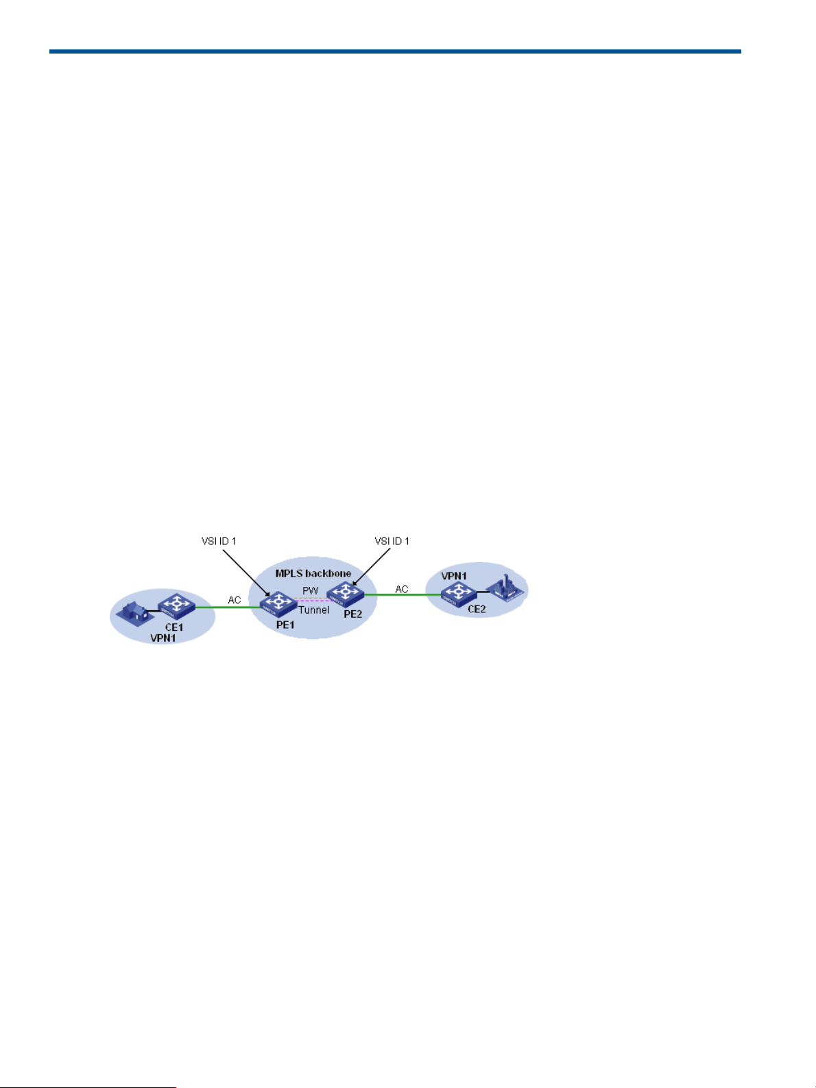
The figure shown above illustrates a typical VPLS networking scenario, which involves the following
basic concepts:
• CE (Customer Edge): Customer edge device that is directly connected with the service provider
network.
• PE (Provider Edge): Provider edge device that connects one or more CEs to the service provider
network, mainly for access to VPN services.
• VSI (Virtual Switch Instance): Virtual switch instance that maps actual VPLS access links to
virtual links. As shown in the above figure, to ensure connectivity between devices, PE 1 and
PE 2 are configured with a VSI respectively, and the VSI ID is 1.
• PW (Pseudo Wire): A pseudo wire is the bidirectional virtual connection between two VSIs.
A pseudo wire consists of two unidirectional virtual circuits (VCs).
• AC (Attachment Circuit): Attachment circuit that connects a CE to a PE. It can use physical
interfaces or virtual interfaces.
• Tunnel: A tunnel, usually an MPLS tunnel, used to carry one or more PWs. It is a direct channel
between a local PE and the peer PE for transparent transmission in-between.
8 L2VPN Manager
Page 9
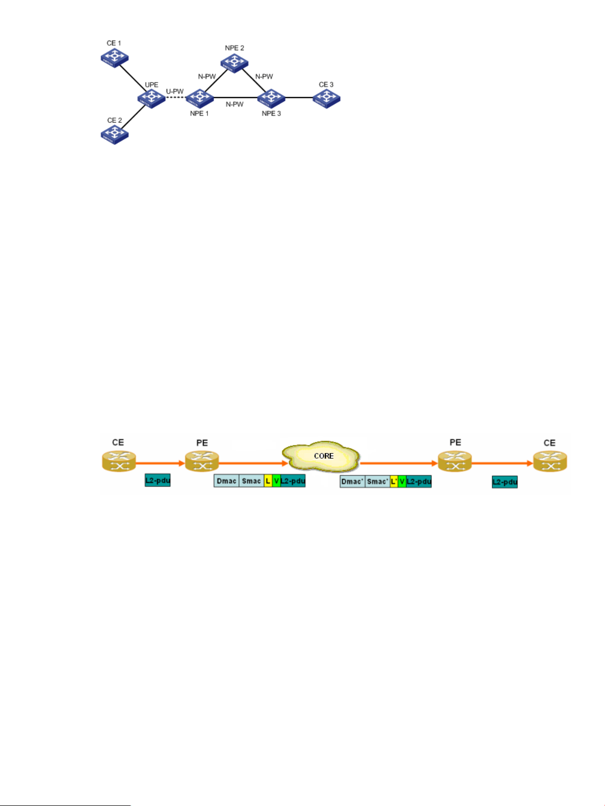
The figure shown above illustrates a typical H-VPLS network, which involves the following basic
concepts:
• UPE (User Facing-Provider Edge): User facing provider edge device that functions as the user
access convergence device.
• NPE (Network Provider Edge): Network provider edge device that functions as the network
core PE. An NPE resides at the edge of a VPLS network core domain and provides transparent
VPLS transport services between core networks.
• U-PW: PW link between a UPE and an NPE.
• N-PW: PW link between two NPEs.
VPLS VPN Types
• LDP VPN: Uses the Label Distribution Protocol (LDP) to establish virtual circuits by establishing
point-to-point sessions between a pair of PEs.
• BGP VPN: Uses the Border Gateway Protocol (BGP) to establish signaling sessions through
route reflectors (RRs) and supports networking across ASs.
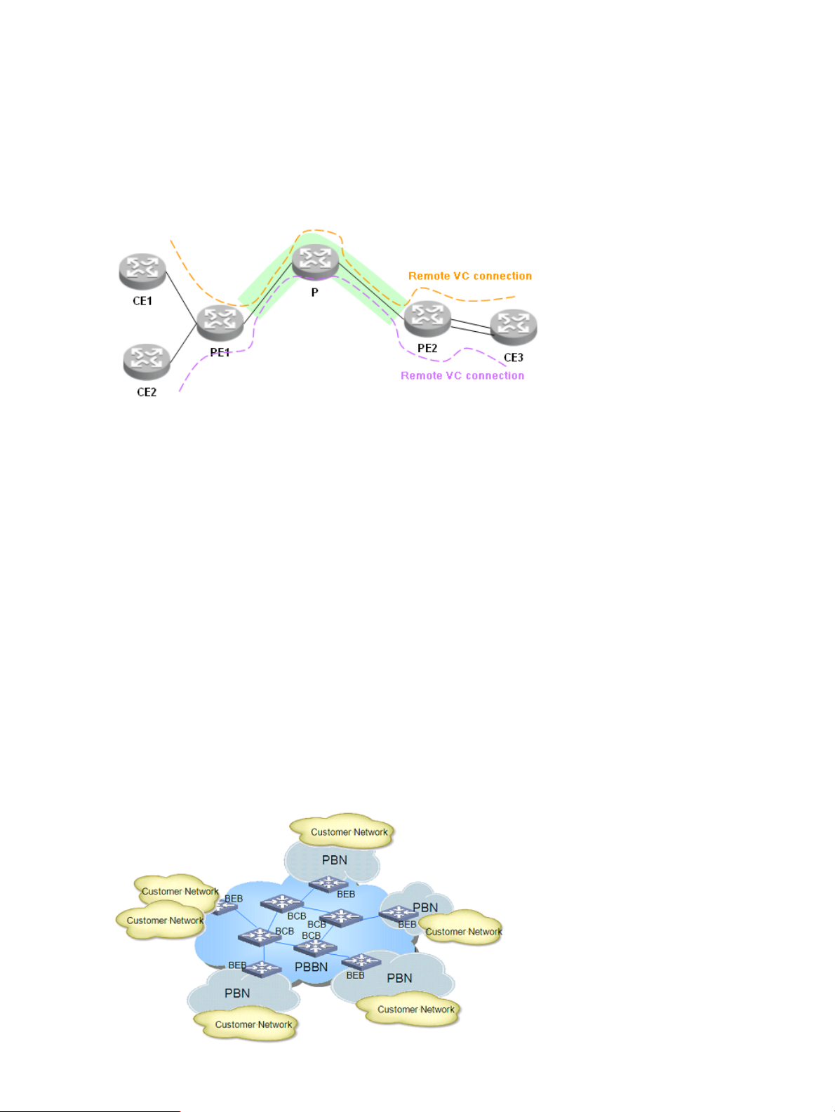
Operation of VPLS
The icon descriptions for the data forwarding flowchart shown above are:
• L2-pdu: Data link layer packet.
• Dmac: MAC address of the next hop device.
• Smac: MAC address of the local device.
• L: Public network label.
• V: Private network label.
• L': Public network label after the packet is forwarded along the LSP.
The data forwarding procedure is as follows:
1. A PE receives a data packet from a CE through the AC. According to the VSI, the PE pushes
its own MAC address, the next hop's MAC address, the public network label, and the private
network label into the packet and then forwards the packet to the core network according to
the next hop's MAC address.
2. After receiving the packet, the core network encapsulates the packet with the new public
network label and the MAC address of the new next hop device, and then forwards the packet
to the specified PE accordingly.
3. The PE sends the packet to the right CE through the AC according to the private network label.
L2VPN Manager Overview 9
Page 10
Basic VLL concepts
VLL(Virtual Leased Line): VLL provides point-to-point L2VPN services over the public network. With
VLL, two sites can communicate as if they were directly connected. VLL is a form of MPLS L2VPN.
It uses inner labels to identify virtual lines (Layer 2 tunnels), hereinafter referred to as virtual circuits
(VCs), and uses outer labels to identify public tunnels. The network devices of the service provider
do not need to maintain any Layer 2 information but perform MPLS forwarding on the public
neworks based on MPLS labels. In VLL, a Forwarding Equivalence Class (FEC) is about the VC
indentifier and some Layer 2 information.
The above figure shows a typical VLL networking scenario. With the existing technologies, VLL can
be implemented mainly in two methods, which use different signaling protocols to exchange VC
information. One method is called Martini (the L2VPN Manager only support this method). The
Martini method uses a standard two-layer label stack. The inner labels (VC labels) are exchanged
through the extended LDP. The Martini draft extends the standard LDP, adding a new FEC type,
the VC FEC, for exchanging VC labels. A VC FEC identifies a VC by VC Type and VC ID. VC Type
indicates the link layer encapsulation type and VC ID uniquely indentifies a VC of the same type
on a PE. The PEs that connect two CEs switch VC labels through LDP and bind the corresponding
CEs by the VC ID. A VC between the two CEs are then established and the two CEs can transport
Layer 2 data over the VC. The Martini method does not provide the local switching function. Outer
labels will be used to transport VCs' data over the service provider network. Because PEs can
identify data of different VCs by inner label, multiple VCs can share the public tunnel.
PBB overview
PBB Overview PBB is proposed to satisfy the Metro Ethernet Network (MEN) requirements. In the
MEN service hierarchy model, PBB is at the carrier level, used to establish MAC tunnels to separate
services of different customers on the backbone. A network employs 802.1ah is called a Provider
Backbone Bridge Network (PBBN).
Basic concepts of PBB
10 L2VPN Manager
Page 11
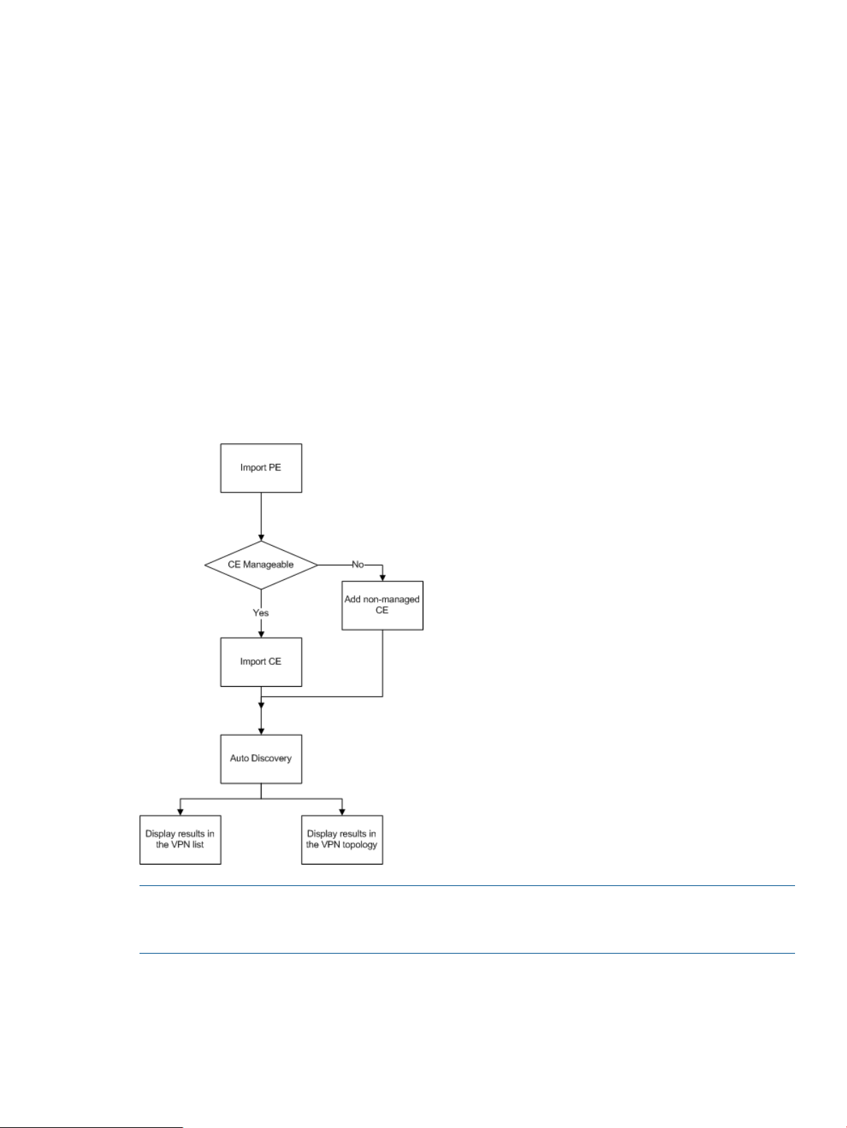
The above figure shows a typical PBB networking scenario. In a typical PBBN, there are two types
of devices, BEB and BCB.
• BEB (Backbone Edge Bridge): Like a PE in an MPLS network. It performs MAC-in-MAC
encapsulation for the incoming packets and then delivers the encapsulated packets to
subsequent devices, which will forward the packets according to the B-MAC and B-VID. It also
de-encapsulates the received MAC-in-MAC packets to standard Ethernet packets and then
looks up the forwarding table and sends the packets from the corresponding outgoing
interfaces.
• BCB (Backbone Core Bridge): Like a P device in an MPLS network. It forwards the received
MAC-in-MAC packets according to the outer B-MAC and B-VID. A BCB only performs packet
bridging, learning the MAC addresses on the backbone. It does not need to learn the huge
number of MAC addresses in the customer networks. This reduces the network deployment
expenses and provides better expansibility for the PBBN.
Usage Summary
The L2VPN Manager mainly provides two operation flows: service flow and deployment flow.
Through this user guide, you can quickly get started with the L2VPN Manager.
Service flow
NOTE: Select imported PE devices and perform automatic discovery. Then, the L2VPN Manager
will find out the VPNs and AC links newly configured on the devices and display them visually in
the topology diagram.
Usage Summary 11
Page 12
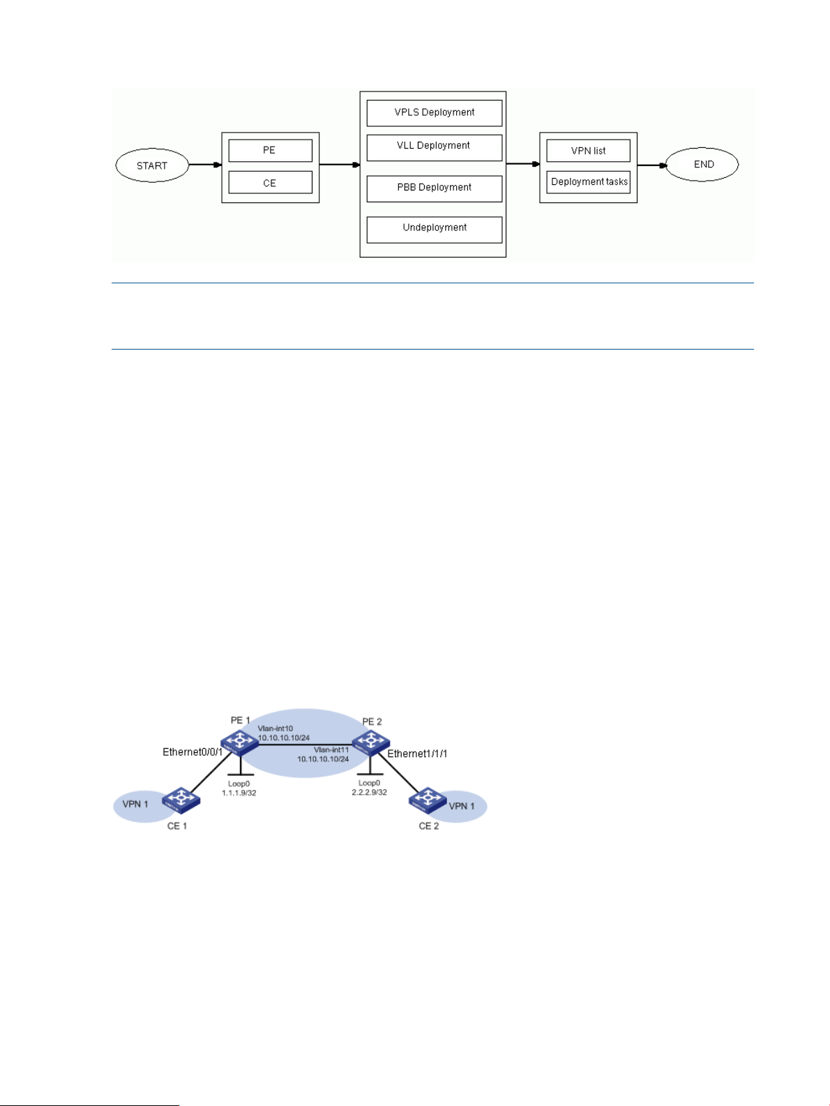
Deployment flow
NOTE: You can add PEs and CEs to a VPN through VPLS deployment, VLL deployment, and PBB
deployment. You can also remove the PEs and CEs from a VPN or remove a whole VPN through
the function.
VPN privilege management
The system allows administrators to authorize different operators to manage different VPNs. When
adding or modifying an operator account, an administrator can authorize the operator to manage
certain VPNs or change which VPNs the operator can manage. Then, after logging on, the operator
can view information about only the VPNs the operator is authorized to manage.
Typical Applications
VPLS Instance Configuration
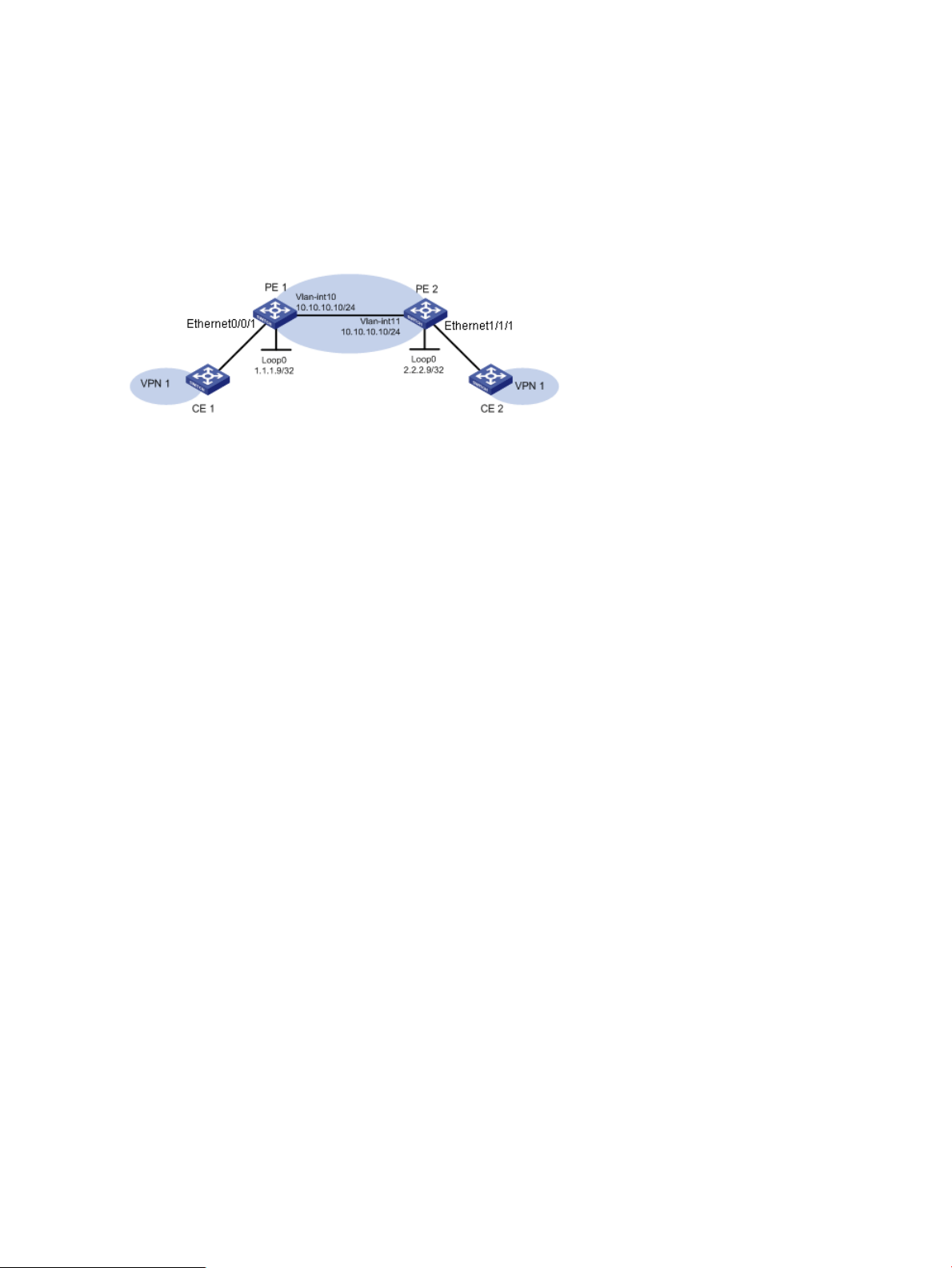
Application scenario
Company H locates in city B and uses PE 1 and CE 1; company Z locates in city N and uses PE
2 and CE 2. PE 1 and PE 2 are enabled with MPLS and L2VPN, and each configured with an LSR
ID. The two companies are going to undertake corporate restructuring through merge into a new
group for the need of business development. The new group decides to use the VPN access service
provided by the server provider to implement network connectivity, so that information and data
can be transferred within the group fast and correctly.
Scenario analysis
Create a VPN using the L2VPN Manager, and then add all network devices in city B and city N
of the group company into the VPN for management.
Operation procedure
1. Add devices to the platform.
a. Select the Homepage tab, and then click Add Devices in the navigation tree.
b. Enter the IP addresses of the devices (PE 1, PE 2, CE 1, and CE 2) to be managed, specify
12 L2VPN Manager
the corresponding Telnet and SNMP parameters, and then click OK to add these devices
to the platform.
Page 13

2. Import PE devices to the L2VPN Manager.
a. Select the Service tab to enter the L2VPN manager system.
b. Select VPN Devices > PE Devices from the navigation tree to enter the PE device list page.
c. Click Import PE to enter the page for importing PE devices.
d. Click Select Device. On the pop-up page, select PE 1 and PE 2. You can query the devices
by specifying the device label, IP, or status.
e. Click OK to return to the page for importing PE devices.
f. Click OK.
3. Import CE devices to the L2VPN Manager.
a. Select VPN Devices > CE Devices from the navigation tree to enter the CE device list page.
b. Click Import CE to enter the page for importing CE devices.
c. Click Select Device. On the pop-up page, select CE 1 and CE 2. You can query the devices
by specifying the device label, IP, status, or CE type.
d. Click OK to return to the page for importing CE devices.
e. Click OK.
4. Set up a VPN.
a. Select VPN Deployment > VPLS Deployment in the navigation tree to enter the VPLS VPN
deployment guide page.
b. Select PE as the PE type.
c. Input VPN name VPN1, audit interval, description, and contact person in the basic VPN
information area.
d. Input the VSI ID, and select the PW transfer mode.
e. Click Next to enter the PE configuration page.
5. Configure PE interface.
a. On the PE configuration page, click Select PE and then select a PE device (PE 1) on the
pop-up page.
b. Click the Modify icon to enter the UNI configuration page.
c. Click the Select button behind the UNI Interface text box. On the pop-up page, select a
PE device interface.
d. Input the service instance and encapsulation VLAN for the UNI interface.
e. Click the Select button behind the CE Device text box. On the pop-up page, select a CE
device (CE 1).
f. Click OK to finish the PE configuration.
g. Click Next to enter the configuration summary page.
6. View configuration summary.
a. On the configuration summary page, to immediately deploy the configuration commands
to the devices, click Deploy Immediately.
b. Click OK to enter the deployment task list page. Add the link between PE 2 and CE 2 in
the same way.
7. View the topology.
a. Select VPN Resources > VPN List in the navigation tree to enter the VPN list page.
b. Click the VPN Topology icon of VPN1 to view the topology information of the VPN.
Configuration guidelines
On the configuration summary page, you can deploy the configuration to the devices immediately.
Otherwise, the links will appear only on the topology diagram, with the status being Undeployed.
Typical Applications 13
Page 14
VLL Instance Configuration
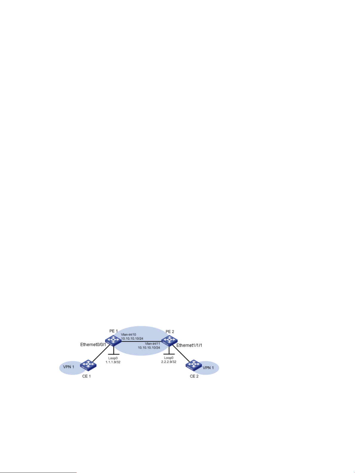
Application scenario
Company H locates in city B and uses PE 1 and CE 1; company Z locates in city N and uses PE
2 and CE 2. PE 1 and PE 2 are enabled with MPLS and MPLS L2VPN, and each configured with
an LSR ID. The two companies are going to undertake corporate restructuring through merge into
a new group for the need of business development and strategic planning. The new group decides
to establish a VPN through VLL to implement network connectivity, so that information and data
can be transferred within the group fast and correctly.
Scenario analysis
Create a VLL VPN by using the L2VPN manager, and then add all network devices in city B and
city N of the group company into the VPN for management. VLL VPN is suitable for point-to-point
links. For point-to-multipoint links, you are recommended to use VPLS VPN.
Operation procedure
1. Add devices to the platform.
a. Select the Homepage tab, and then click Add Devices in the navigation tree.
b. Enter the IP addresses of the devices (PE 1, PE 2, CE 1, and CE 2) to be managed, specify
the corresponding Telnet and SNMP parameters, and then click OK to add these devices
to the platform.
2. Import PE devices to the L2VPN Manager.
a. Click the Service tab on the navigation bar.
b. Select VPN Devices > PE Devices in the navigation tree.
c. Click Import PE to enter the page for importing PE devices.
d. Click Select Device. On the pop-up page, select PE 1 and PE 2. You can query the devices
by specifying the device label, IP, or status.
e. Click OK to return to the page for importing PE devices.
f. Click OK.
3. Import CE devices to the L2VPN manager.
a. Select VPN Devices > CE Devices in the navigation tree.
b. Click Import CE to enter the page for import CE devices.
c. Click Select Device. On the pop-up page, select CE 1 and CE 2. You can query the devices
by specifying the device label, IP, status, or CE type.
d. Click OK to return to the page for importing CE devices.
e. Click OK.
4. Set up a VPN.
a. Select VPN Deployment > VLL Deployment in the navigation tree.
b. Type the basic VPN information, such as VPN name VPN1, audit interval, description,
contact person, and PW ID, and select the PW transport mode.
c. Click Next to enter the local PE configuration page.
5. Configure the local PE (PE1).
14 L2VPN Manager
Page 15
a. On the local PE configuration page, click the Select button behind the UNI Interface text
box. On the pop-up page, select the PE interface connecting CE 1.
b. Type the service instance and encapsulation VLAN for the UNI interface, and select the
encapsulation type.
c. Click the Select button behind the CE Device text box. On the pop-up page, select a CE
device (CE 1).
d. Click Next to enter the remote PE configuration page.
6. Configure the remote PE (PE2).
a. On the remote PE configuration page, click the Select button behind the UNI Interface
text box. On the pop-up page, select the PE interface connecting CE 2.
b. Select an encapsulation type for the UNI interface.
c. Click the Select button behind the CE Device text box. On the pop-up page, select a CE
device (CE 2).
d. Click Next to enter the configuration summary page.
7. View configuration summary.
a. On the configuration summary page, to immediately deploy the configuration commands
to the devices, click Deploy Immediately.
b. Click OK to enter the deployment task list page.
8. View the topology.
a. Select VPN Resources > VPN List in the navigation tree.
b. Click the VPN Topology icon of VPN1 to view the topology information of the VPN.
Precautions
On the configuration summary page, you can configure to deploy the configuration to the devices
immediately. Otherwise, the links will appear only on the topology diagram, with the status being
Undeployed.
PBB Instance Configuration
Application scenario
Company H locates in city B and uses PE 1 and CE 1; company Z locates in city N and uses PE
2 and CE 2. PE 1 and PE 2 are enabled with L2VPN. The two companies are going to undertake
corporate restructuring through merge into a new group for the need of business development and
strategic planning. The new group decides to establish a VPN through PBB to implement network
connectivity, so that information and data can be transferred within the group fast and correctly.
Scenario analysis
Create a PBB VPN by using the L2VPN manager, and then add all network devices in city B and
city N of the group company into the VPN for management.
Operation procedure
1. Add devices to the platform.
Typical Applications 15
Page 16

a. Select the Homepage tab, and then click Add Devices in the navigation tree.
b. Enter the IP addresses of the devices (PE 1, PE 2, CE 1, and CE 2) to be managed, specify
the corresponding Telnet and SNMP parameters, and then click OK to add these devices
to the platform.
2. Import PE devices to the L2VPN Manager.
a. Click the Service tab on the navigation bar.
b. Select VPN Devices > PE Devices in the navigation tree.
c. Click Import PE to enter the page for importing PE devices.
d. Click Select Device. On the pop-up page, select PE 1 and PE 2. You can query the devices
by specifying the device label, IP, or status. Click OK to return to the page for importing
PE devices.
e. Click OK.
3. Import CE devices to the L2VPN manager.
a. Select VPN Devices > CE Devices in the navigation tree.
b. Click Import CE to enter the page for import CE devices.
c. Click Select Device. On the pop-up page, select CE 1 and CE 2. You can query the devices
by specifying the device label, IP, status, or CE type. Click OK to return to the page for
importing CE devices.
d. Click OK.
4. Set up a VPN.
a. Select VPN Deployment > PBB Deployment in the navigation tree.
b. Type the basic VPN information, such as VPN name VPN1, audit interval, description,
contact person, I-SID, and B-VLAN, and select the PW transport mode.
c. Click Next to enter the PE configuration page.
5. Configure PE interface.
a. On the PE configuration page, click Select PE and then select a PE device (PE 1) on the
pop-up page.
b. Click the icon to enter the UNI and NNI configuration page.
c. Click the Select button behind the UNI Interface text box. On the pop-up page, select a
PE interface.
d. Type the service instance and encapsulation VLAN for the UNI interface, and select the
encapsulation type.
e. Click the Select button behind the CE Device text box. On the pop-up page, select a CE
device (CE 1).
f. Click the Select button behind the Uplink Interface text box. On the pop-up page, select
one or more PE interfaces.
g. Click OK.
h. Click Next to enter the configuration summary page.
6. View configuration summary.
a. On the configuration summary page, to immediately deploy the configuration commands
to the devices, click Deploy Immediately.
b. Click OK to enter the deployment task list page.
c. Add the link between PE 2 and CE 2 in the same way.
7. View the topology.
a. Select VPN Resources > VPN List in the navigation tree.
b. Click the icon of VPN1 to view the topology information of the VPN.
16 L2VPN Manager
Page 17

Precautions
On the configuration summary page, you can configure to deploy the configuration to the devices
immediately. Otherwise, the links will appear only on the topology diagram, with the status being
Undeployed.
Using L2VPN Manager
The L2VPN Manager provides four functions: VPN devices, VPN resources, VPN deployment, and
automatic discovery.
• VPN Devices—VPN devices include PE devices and CE devices. CE devices include managed
CEs and non-managed CEs. The PEs and non-managed CEs can be directly imported from
the platform to the L2VPN manager. For non-managed CEs, however, you need to add them
to the L2VPN Manager manually.
• VPN Resources—The L2VPN Manager allows you to add VPNs manually or use the automatic
discovery function to construct VPNs automatically. VPN resources include VPN list and VC
list. On the VPN list page, you can add, delete, and audit a VPN, and view the detailed
information, audit information, and topology information of a VPN. On the AC list page, you
can query and delete ACs, and view the detailed information of a VC.
• VPN Deployment—VPN Deployment includes VPLS deployment, VLL deployment, PBB
deployment, undeployment, and deployment task management. You can deploy configuration
one by one or in a batch. The L2VPN Manager provides a simple, visual deployment operation
guide, which can release you from remembering bald command lines and reduce your
workload tremendously. After the deployment, you can view the deployment details (by clicking
the Details icon) to see the configuration commands deployed to the devices.
• Automatic Discovery—The L2VPN Manager can find the newly configured VPNs and AC links
on devices through the automatic discovery function and then add them to the L2VPN Manager
for management. The L2VPN Manager can discover the entire VPN network. No manual
interference is needed during automatic discovery.
VPN devices
VPN devices include PEs and CEs. A PE is a service provider edge device, which is the core of
VPN service processing in a network. A CE is an edge device of a VPN site network, representing
a customer subnet.
A device can be managed by the L2VPN Manager only after the device is added to the platform.
That is, the related device should be managed by the platform before it can be added to the L2VPN
Manager as a PE or CE resource. Each device can be imported as only one type of VPN device
at a time. VPN resources allows for such operations as querying, adding, deleting, and editing
managed devices.
Due to the deployment variety of CEs, some CEs cannot be managed. You can create non-managed
CEs in the L2VPN Manager to substitute the real CEs. A non-managed CE also represents a customer
site. Non-managed CEs help to represent the connectivity between PEs and actual customer sites
in the network topology.
PE devices
PEs are the most important device resources in the L2VPN Manager. The system discovers VPNs
and VPN links by obtaining information on PEs. VPLS VPN network deployment is also performed
on PEs.
You can import, query, synchronize, and delete PEs, and view detailed information about a PE.
The information displayed on a PE details page varies with the VPN type you selected during VPN
deployment. For example, if you have deployed a VLL VPN, the PE details page displays VLL
information.
Using L2VPN Manager 17
Page 18

Import PE
Use this function to import one or more PEs from the platform to the L2VPN Manager. For VPLS
and VLL networking, a device can be imported as a PE only if it is enabled with MPLS and MPLS
L2VPN and configured with an LSR ID. For PBB networking, a device can be imported as a PE if
it is enabled with L2VPN.
Operation procedure
1. Click the Service tab on the top navigation bar, and then select VPN Devices > PE Devices in
the navigation tree to enter the PE list page.
2. Click Import PE to enter the device import page.
3. Click the Select Device button. On the pop-up page, select the devices to be imported and
click OK to return to the device import page.
4. Click OK.
Precautions
• The L2VPN Manager allows only one device import operation (CE or PE import) at a time.
• Each device can be imported as one type at a time. For example, if a device is imported as
a PE, you can import the device as a CE only after you remove the device from the PE device
list.
Query PE
Use this function to query PE devices based on device label, device IP address, or device status.
Operation Procedure
1. Click the Service tab on the top navigation bar, and then select VPN Devices > PE Devices in
the navigation tree to enter the PE list page.
2. Enter query criteria.
3. Click Query. The queried PEs are displayed on the PE device list. To display all the PEs, click
Reset.
Precautions
• All the query criteria support fuzzy match.
Delete PE
Use this function to delete existing PEs in the L2VPN Manager. When this operation succeeds, the
corresponding PEs and links are deleted from the L2VPN Manager.
Operation Procedure
1. Click the Service tab on the top navigation bar, and then select VPN Devices > PE Devices in
the navigation tree to enter the PE list page.
2. Select one or more PEs you want to delete.
3. Click Delete.
Precautions
• You can delete a PE from the L2VPN Manager without affecting the corresponding device in
the platform. If a PE is deleted in the platform, the device is also deleted in the L2VPN Manager.
• If a PE is deleted from the platform or the L2VPN Manager, all the VSI, VLL, and AC information
related to the PE are also deleted.
18 L2VPN Manager
Page 19

Synchronize PEs immediately
Use this function to synchronize the configuration of a PE to that on the L2VPN Manager. From the
PE device list, check the last synchronization time and synchronization status of a PE to determine
whether the current configuration of the PE is valid.
Operation Procedure
1. Click the Service tab on the top navigation bar, and then select VPN Devices > PE Devices in
2. Enter query criteria.
3. Click Query. The queried PEs are displayed on the PE device list. To display all the PEs, click
Precautions
• During PE device synchronization, the information on the device is read to the L2VPN Manager.
• If the VPN target information of different VSIs on a PE is the same, synchronization of the PE
CE devices
CEs are important device resources in the L2VPN Manager. Depending on management status,
CEs fall into two categories: manageable CE and non-managed CE.
Managed CEs can be imported directly from the platform, while non-managed CEs need to be
created in the L2VPN Manager manually.
the navigation tree to enter the PE list page.
Reset.
This may take some time.
will fail.
Query CE device
Use this function to query managed CE devices and non-managed CE devices based on such query
criteria as device label and device IP address.
Operation Procedure
1. Click the Service tab on the top navigation bar, and then select VPN DevicesCE Devices in the
navigation tree to enter the CE list page.
2. Enter query criteria.
3. Click Query. The queried devices are displayed on the CE device list. To display all the
managed CEs and non-managed CEs, click Reset.
Precautions
All the query criteria support fuzzy match.
Import CE
Use this function to import one or more CEs from the platform to the L2VPN Manager.
Operation Procedure
1. Click the Service tab on the top navigation bar, and then select VPN DevicesCE Devices in the
navigation tree to enter the CE list page.
2. Click Import CE to enter the device import page.
3. Click the Select Device button. On the pop-up page, select the devices to be imported and
click OK to return to the device import page
4. Click OK.
Using L2VPN Manager 19
Page 20

Delete CE
Use this function to delete existing CE devices in the L2VPN Manager, including managed CE
devices and non-managed CE devices. When this operation succeeds, the corresponding managed
CEs, non-managed CEs, and links are deleted from the L2VPN Manager.
Operation Procedure
1. Click the Service tab on the top navigation bar, and then select VPN DevicesCE Devices in the
navigation tree to enter the CE list page.
2. Select one or more CEs you want to delete.
3. Click Delete.
Precautions
You can delete a managed CE from the L2VPN Manager without affecting the corresponding
device in the platform. If a device is deleted in the platfom, the device is also deleted in the L2VPN
Manager.
If a CE is deleted from the platform or L2VPN Manager, all AC information related to the CE is
also deleted.
Add non-managed CE
Use this function to identify the CEs that do not need to be managed by the L2VPN Manager but
whose connections need to be represented in the topology. This function allows you to add
non-managed CEs to the L2VPN Manager.
Operation Procedure
1. Click the Service tab on the top navigation bar, and then select VPN DevicesCE Devices in the
navigation tree to enter the CE list page.
2. Click Add VCE to enter the page for adding non-managed CEs.
3. Enter a device label and MAC address.
4. Click OK.
Precautions
Device labels and MAC addresses must be unique.
Use this function to modify the device label and MAC address of a CE.
Modify non-managed CE
Use this function to modify the device label and MAC address of a CE.
Operation procedure
1. Click the Service tab on the top navigation bar, and then select VPN DevicesCE Devices in the
navigation tree to enter the CE list page.
2. Click the Modify icon corresponding to the non-managed CE device to be modified to enter
the page for modifying a non-managed CE.
3. Modify the device label and MAC address.
4. Click OK.
Precautions
A device label and MAC address must be unique.
Query VLAN mapping
Use this function to query the VLAN mapping relation for all interfaces of a CE.
20 L2VPN Manager
Page 21

Operation procedure
1. Click the Servicetab on the top navigation bar, and then select VPN Devices > CE Devices in
the navigation tree to enter the CE list page.
2. Click the VLAN Mapping icon of a CE to enter the page for VLAN mapping list.
Add VLAN mapping
Use this function to add the VLAN mapping relation for all interfaces of a CE.
Operation Procedure
1. Click the Service tab on the top navigation bar, and then select VPN DevicesCE Devices in the
navigation tree to enter the CE list page.
2. Click the VLAN Mapping icon of a CE to enter the page for VLAN mapping list.
3. Click Add to enter the page for add VLAN mapping.
4. Click Select and on the pop-up page, select an interface, and then click OK.
5. Click Add in the VLAN mapping list.
6. In the pop-up window, type the source VLAN ID and Destination VLAN ID, and then click OK.
7. Repeat procedures 5 and 6 to add more relations.
8. Click OK on the add VLAN mapping page
Delete VLAN mapping
Use this function to delete the VLAN mapping relation for all interfaces of a CE.
Operation Procedure
1. Click the Service tab on the top navigation bar, and then select VPN DevicesCE Devices in the
navigation tree to enter the CE list page.
2. Click the icon of a CE to enter the page for VLAN mapping list.
3. Select one or more VLAN mapping relations you want to delete.
4. Click OK.
VPN deployment
The L2VPN Manager provides the VPN deployment function that allows for simple and user-friendly
operations. You do not need to go to different labs or use command lines to configure a VPN. This
greatly reduces the time and working load for maintenance.
VPN deployment consists of VPLS deployment, VLL deployment, PBB deployment, undeployment,
and deployment task management. VPLS/VLL/VBB deployments allow you to conveniently add PE
devices to a VPN in different ways and connect PEs with CEs. Undeployment allows you to remove
PEs from a VPN or remove links between PEs and CEs. Deployment task management allows you
to view the deployment tasks, modify a deployment task, and deploy the configuration in a task
to devices.
This function cannot be used when BGP VPN is selected on the global parameter configuration
page.
VPLS deployment
This function helps you configure and deploy a VPN of VPLS type. After you configure a VPLS VPN,
if you do not deploy the VPN configuration immediately, a deployment task in state of "undeployed"
is added on the deployment task list. If you deploy the VPN configuration immediately, a deployment
task in state of "deploying" is added on the deployment task list. After the deployment, you can
view the deployment result.
Using L2VPN Manager 21
Page 22

Configuration procedure
1. Define VPN.
This function allows you to configure a VPN's basic information, including VPLS VPN networking
type (PE Type), VPN name, VSI ID, PW transport mode, audit interval, VPN description, and
contact information.
Precautions
• Valid characters in a VPN name are letters, digits, and underscores.
• VSI ID is generated randomly. You can modify it in the range 1 to 4294967295.
• PW transport mode can be VLAN or Ethernet. VLAN is the default.
• Audit interval ranges from 0 to 24 and defaults to 24. A value of 0 means no audit.
• Contact is the current login user by default.
• If you select PE for the PE type, skip step 3 and go to step 4 directly after you finish the
PE interface configuration.
2. PE or NPE configuration.
This function allows you to configure the PE information and AC information for a VPLS VPN.
The PE information includes PE name. The AC information includes UNI interface, service
instance, bandwidth, encapsulation type, encapsulation VLAN, access type, and CE device.
Steps to configure AC information
a. Click Add in the AC list area, and then on the pop-up page, select a PE interface.
b. Type the service instance, encapsulation VLAN and bandwidth, and select the
encapsulation type and access type.
c. Click Select behind the CE Device text box, and then on the pop-up page, select a CE
device.
d. Click OK.
• To configure the PE information, click Add in the PE device list, and then on the pop-up
page, select one or multiple PE devices.
Precautions
• You can only type a number in the range 1 to 4094 in the service instance text box.
• You can only type a number in the range 1 to 1000 in the bandwidth text box.
• Encapsulation VLAN IDs are in the range 1 to 4094. You can specify one or more VLAN
IDs or VLAN ID ranges. To specify a VLAN range, use a hyphen (-) between the start and
end VLAN IDs of the range. To specify multiple VLAN ranges, use a dot (,) to separate
two VLAN ranges. The specified VLAN ID(s) and VLAN ID range(s) must be in the
ascending order. For example: 2, 4-6, 8-10
• The access type can be VLAN or Ethernet. VLAN is the default.
• If you do not select a CE device, the system automatically adds a VCE.
• If the encapsulation type is S-VID or S-VID Only Tagged, you must enter the encapsulation
• If the PE device you select when you configure AC information is not in the PE device list,
3. UPE configuration.
This function allows you to configure the UPE information and AC information for a VPLS VPN.
The PE information includes PE name, Main NPE and Backup NPE. The AC information includes
22 L2VPN Manager
VLAN IDs.
the system automatically adds the PE to the PE device list.
Page 23

UNI interface, service instance, bandwidth, encapsulation type, encapsulation VLAN, access
type, and CE device.
Steps to configure AC information
a. Click Add in the AC list area, and then on the pop-up page, select a PE interface.
b. Type the service instance, encapsulation VLAN and bandwidth, and select the
encapsulation type and access type.
c. ClickSelect behind the CE Device text box, and then on the pop-up page, select a CE
device.
d. Click OK.
Steps to configure PE information
a. Click Add in the PE device list area, and then on the pop-up page, select one or multiple
PE devices.
b. On the PE device list, select one or multiple PE devices, click the Main NPE button, and
then on the pop-up page, select one PE device.
c. On the PE device list, select one or multiple PE devices, click the Backup NPE button, and
then on the pop-up page, select one PE device.
Precautions
• You can only type a number in the range 1 to 4094 in the service instance text box.
• You can only type a number in the range 1 to 1000 in the bandwidth text box.
• Encapsulation VLAN IDs are in the range 1 to 4094. You can specify one or more VLAN
IDs or VLAN ID ranges. To specify a VLAN range, use a hyphen (-) between the start and
end VLAN IDs of the range. To specify multiple VLAN ranges, use a dot (,) to separate
two VLAN ranges. The specified VLAN ID(s) and VLAN ID range(s) must be in the
ascending order. For example: 2, 4-6, 8-10
• The access type can be VLAN or Ethernet. VLAN is the default.
• If you do not select a CE device, the system automatically adds a VCE.
• If the encapsulation type is S-VID or S-VID Only Tagged, you must enter the encapsulation
VLAN IDs.
• If the PE device you select when you configure AC information is not in the PE device list,
the system automatically adds the PE to the PE device list.
4. Configuration summary.
This function displays the configuration commands to be deployed to PE devices.
a. Select Deploy Immediately, and click OK.
Precautions
• The configuration commands are generated by the system automatically. You cannot
modify them.
• If you do not select Deploy Immediately, the system only creates the VPN and adds an
"Undeployed" deployment task to the deployment task list. You can deploy the
configuration later. If you select Deploy Immediately, the system deploys the configuration
to the devices immediately. A CE device and a link between the CE device and PE device
are added on the L2VPN Manager and the deployed configuration is recorded on the
related devices.
Using L2VPN Manager 23
Page 24

VLL Deployment
This function helps you configure and deploy a VPN of VLL type. After you configure a VLL VPN,
if you do not deploy the VPN configuration immediately, a deployment task in state of "undeployed"
is added on the deployment task list. If you deploy the VPN configuration immediately, a deployment
task in state of "deploying" is added on the deployment task list. After the deployment, you can
view the deployment result.
Configuration procedure
1. Define VPN.
This function allows you to configure a VPN's basic information, including VPN name, PW
ID, PW transport mode, audit interval, VPN description, and contact information.
Precautions
• Valid characters in a VPN name are letters, digits, and underscores.
• PW ID is generated randomly. You can modify it in the range 1 to 4294967295.
• PW transport mode can be VLAN or Ethernet. VLAN is the default.
• Audit interval ranges from 0 to 24 and defaults to 24. A value of 0 means no audit.
• Contact is the current login user by default.
2. Local PE configuration.
This function allows you to configure the local PE and interface information for a VLL VPN,
including PE name, UNI interface, service instance, bandwidth, encapsulation type,
encapsulation VLAN, access type, and CE device.
a. For PE configuration, click Select following the interface description, and then on the
b. For CE configuration, click Select following the device label, and then select a CE device.
pop-up page, select a PE and an interface. If you select a Layer 2 interface, you must
select the encapsulation type and enter the service instance ID and bandwidth.
If you do not select a CE device, the system automatically adds a VCE.
Precautions
• You can only type a number in the range 1 to 4094 in the service instance text box.
• You can only type a number in the range 1 to 1000 in the bandwidth text box.
• Encapsulation VLAN IDs are in the range 1 to 4094. You can specify one or more VLAN
IDs or VLAN ID ranges. To specify a VLAN range, use a hyphen (-) between the start and
end VLAN IDs of the range. To specify multiple VLAN ranges, use a dot (,) to separate
two VLAN ranges. The specified VLAN ID(s) and VLAN ID range(s) must be in the
ascending order. For example: 2, 4-6, 8-10
• The access type can be VLAN or Ethernet. VLAN is the default.
• If the encapsulation type is S-VID or S-VID Only Tagged, you must enter the encapsulation
VLAN IDs.
3. Remote PE configuration.
This function allows you to configure the peer PE and interface information for a VLL VPN,
including PE name, UNI interface, service instance, bandwidth, encapsulation VLAN,
24 L2VPN Manager
Page 25

encapsulation type, and CE device. Refer to the "local PE configuration" part for the operation
procedure and precautions.
4. Configuration summary.
This function displays the configuration commands to be deployed to PE devices.
a. On the remote PE configuration page, click Next to enter the summary page.
Precautions
• The configuration commands are generated by the system automatically. You cannot
• If you do not select Deploy Immediately, the system only creates the VPN and adds an
PBB deployment
This function helps you configure and deploy a VPN of PBB type. After you configure a PBB VPN,
if you do not deploy the VPN configuration immediately, a deployment task in state of "undeployed"
is added on the deployment task list. If you deploy the VPN configuration immediately, a deployment
task in state of "deploying" is added on the deployment task list. After the deployment, you can
view the deployment result.
1. Define VPN.
This function allows you to configure a VPN's basic information, including VPN name, I-SID,
B-VLAN, PW transport mode, audit interval, VPN description, and contact information.
modify them.
"Undeployed" deployment task to the deployment task list. You can deploy the
configuration later. If you select Deploy Immediately, the system deploys the configuration
to the devices immediately. A CE device and a link between the CE device and PE device
are added on the L2VPN Manager and the deployed configuration is recorded on the
related devices.
Precautions
• Valid characters in a VPN name are letters, digits, and underscores.
• I-SID is generated randomly. You can modify it in the range 1 to 16777215.
• B-VLAN is 1 by default. You can modify it in the range 1 to 4094.
• PW transport mode can be VLAN or Ethernet. VLAN is the default.
• Audit interval ranges from 0 to 24 and defaults to 24. A value of 0 means no audit.
• Contact is the current login user by default.
2. PE configuration.
This function allows you to configure the PE information and AC information for a PBB VPN.
The PE information includes PE device name and NNI interface. The AC information includes
UNI interface, service instance, bandwidth, encapsulation type, encapsulation VLAN, access
type, and CE device.
Steps to configure the AC information
a. Click the Add button in the AC list area, and then on the pop-up page, select a PE
interface.
b. Type the service instance ID, encapsulation VLAN ID and bandwidth, and select the
encapsulation type and access type.
c. Click the Select button behind the CE Device text box, and then on the pop-up page,
select a CE device.
d. Click OK.
Using L2VPN Manager 25
Page 26

Steps to configure the PE information
a. Click the Add button in the PE device list area, and then on the pop-up page, select one
or multiple PE devices.
b. Click the Modify icon in the Configuration column, and then on the pop-up page, select
one or multiple PE interfaces.
Precautions
• For service instance, you can only type a number in the range 1 to 4094.
• For bandwidth, you can only type a number in the range 1 to 1000.
• Encapsulation VLAN IDs are in the range 1 to 4094. You can specify one or more VLAN
IDs or VLAN ID ranges. To specify a VLAN range, use a hyphen (-) between the start and
end VLAN IDs of the range. To specify multiple VLAN ranges, use a dot (,) to separate
two VLAN ranges. The specified VLAN ID(s) and VLAN ID range(s) must be in the
ascending order. For example: 2, 4-6, 8-10
• The access type can be VLAN or Ethernet. VLAN is the default.
• If you do not select a CE device, the system automatically adds a VCE.
• If the encapsulation type is S-VID or S-VID Only Tagged, you must enter the encapsulation
VLAN IDs.
• If the PE device you select when you configure AC information is not in the PE device list,
the system automatically adds the PE to the PE device list.
3. Configuration summary.
This function displays the configuration information to be deployed to PE devices.
a. Select Deploy Immediately, and click OK.
Undeployment
This function is used to undeploy the configuration information from devices. Undeployment supports
three operations: undeploy VPNs, undeploy PEs, and undeploy AC links.
Undeploy an entire VPN
1. Select VPN.
Precautions
• The configuration commands are generated by the system automatically. You cannot
modify them.
• If you do not select Deploy Immediately, the system only creates the VPN and adds an
"Undeployed" deployment task to the deployment task list. You can deploy the
configuration later. If you select Deploy Immediately, the system deploys the configuration
to the devices immediately. A CE device and a link between the CE device and PE device
are added on the L2VPN Manager and the deployed configuration is recorded on the
related devices.
a. Click the Service tab on the top navigation bar, and then select VPN Deployment >
Undeploymentin the navigation tree to enter the undeployment page.
b. Click Select to select the VPN that you want to undeploy.
26 L2VPN Manager
Page 27

c. Select Undeploy VPN from the Undeploy Operation drop-down list.
d. Click Next.
2. Configuration summary.
This step displays the commands to be deployed to devices.
a. Click OK to deploy the commands to devices. If you also selected Also Delete VPN, the
VPN will be removed from the VPN list; If you do not select this option, the VPN will be
kept on the VPN list and only the devices and links in the VPN will be deleted.
Undeploy PEs
1. Select VPN.
a. Click the Service tab on the top navigation bar, and then select VPN Deployment >
Undeployment in the navigation tree to enter the undeployment page.
b. Click Select to select the VPN that you want to undeploy.
c. Select Undeploy PE from the Undeploy Operation drop-down list.
d. Click Next.
2. Select PE device.
This step allows you to select the PEs to be undeployed from the VPN. By default, all PEs are
listed.
a. Click Delete to remove the selected PEs from the list.
b. Click Add to add PEs in the VPN to the list.
c. After you select the PEs to be undeployed, click Next.
3. Configuration summary.
This step displays the commands to be deployed to devices.
a. Click OK to deploy the commands to devices.
Undeploy AC links
1. Select VPN.
a. Click the Service tab on the top navigation bar, and then select VPN Deployment >
Undeployment in the navigation tree to enter the undeployment page.
b. Click Select to select the VPN that you want to undeploy.
c. Select Undeploy AC from the Undeploy Operation drop-down list.
d. Click Next.
2. Select AC.
This step allows you to select the AC links to be undeployed from the VPN. By default, all AC
links in the VPN are listed.
a. Click Delete to remove the selected AC links from the list.
b. Click Add to add AC links to the VPN to the list.
c. After you select the AC links to be undeployed, click Next.
3. Configuration summary.
This step displays the commands to be deployed to devices.
a. Click OK to deploy the commands to devices.
Precautions
• If a VPN has a deployment task in the state of "undeployed", you cannot undeploy the VPN.
• After you confirm your undeployment operation, the undeployment commands are applied to
devices immediately, and a task in the state of "deploying" is added to the deployment task
Using L2VPN Manager 27
Page 28

list. After the task is deployed, you can refresh the deployment task list to view the deployment
status.
Deployment task management
This function allows authorized operators to view all VPN deployment tasks, delete and modify
deployment tasks, view task details and task deployment failure reasons.
Query deployment task
This function allows you to query deployment tasks by VPN name, deployment status, VPN type,
and deployment operation type.
Configuration procedure
1. Click the Service tab on the top navigation bar, and then select VPN Deployment > Deployment
Tasks in the navigation tree to enter the deployment task list page.
2. Type the query parameters.
3. Click Query to display the matched deployment tasks. To display all deployment tasks, click
Reset.
Precautions
Fuzzy match is supported for query by VPN name.
Deploy deployment task
This function is used to deploy the configurations in the deployment tasks whose deployment status
is Undeployed and Failure.
Configuration procedure
1. Click the Service tab on the top navigation bar, and then select VPN Deployment > Deployment
Tasks in the navigation tree to enter the deployment task list page.
2. Select one or more deployment tasks to be deployed.
3. Click Deploy to Devices to deploy the configuration information to the devices.
Precautions
This function can be used to deploy only the deployment tasks whose deployment status is
Undeployed and Failure.
Delete deployment task
This function allows you to delete one or more deployment tasks at a time.
Configuration procedure
1. Click the Service tab on the top navigation bar, and then select VPN Deployment > Deployment
Tasks in the navigation tree to enter the deployment task list page.
2. Select one or more deployment tasks.
3. Click Delete and confirm your operation.
Precautions
Deleting a deployment task only removes the deployment task from the list, the corresponding
configuration deployed to the devices will not be deleted.
Modify deployment task
This function is used to modify the device and interface configurations of a deployment task.
28 L2VPN Manager
Page 29

Configuration procedure
1. Click the Service tab on the top navigation bar, and then select VPN Deployment > Deployment
Tasks in the navigation tree to enter the deployment task list page.
2. Click the Modify icon of the deployment task that you want to modify.
3. You will enter the deployment flow of the task and do the modifications. The deployment flow
may be VPLS DeploymentVLL DeploymentPBB Deployment or Undeployment, depending
on the deployment operation type of the task.
Precautions
• Deployment tasks with the deploy operation type of Add VPN or Modify VPN can be modified.
Deployment tasks with the deploy operation type of Undeploy VPN cannot be modified.
• Deployment tasks in the state of Undeployed and Failure can be modified. Deployment tasks
in the state of Success and Deploying cannot be modified, and the system does not provide
the modify link for such deployment tasks.
• The configuration for a VPN cannot be modified. To change the VPN name or description,
go to the VPN list. For more information, see Modify VPN.
• If a deployment task contains configuration for multiple devices, the initial configuration is
displayed on the deployment taks modification page. The configuration commands that have
been deployed to devices are grayed out. The configuration commands not deployed to
devices or failing to be deployed to devices can be modified.
Automatic Discovery
This function can discover VPNs that exist on devices but yet are not added to the L2VPN Manager,
and then add the VPNs to the L2VPN Manager.
Discover VPN
This function is used to find VPNs and links existing on the network according to the VSI information
of PE devices. If you repeat to perform the automatic discovery operation, this function also can
sense the changes of the VPN structure and synchronize the changes to the topology.
Operation Procedure
1. Select the Service tab, and then click Automatic Discovery in the navigation tree to enter the
VPN automatic discovery page.
2. Click Select PE and on the pop-up page, select one or more PE devices, and then click Start.
3. The system starts automatic discovery. After the system finishes the automatic discovery process,
click Next. All discovered VPNs (LDP or BGP VPNs) will be listed.
4. Select VPNs that need interface configuration, and then click Next to enter the Configure
Interface Binding Information page.
Configuration Guidelines
• For the PE devices selected, you can click Delete to delete them together.
• When you click Select PE again, the selected devices will not be listed in the pop-up device
selection page.
Using L2VPN Manager 29
Page 30

Parameters
• Synchronize PE devices before auto discovery: If you select this parameter, the system will
synchronize PE devices before performing automatic discovery, so that the automatic discovery
process can use the updated configuration.
• Status: Displays the status information of the discovered VPNs. The status can be one of the
following:
◦ Existed: Indicates that system finds new links that belong to the VPN.
◦ New VPN: Indicates that the VPN is newly discovered this time.
• VPN Name: Uses the VSI name on the device by default. If the VPN name conflicts with an
existing VPN, it uses this format: VPN name-auto incremental number. For example, VPN
name-1, VPN name-2, and so on.
• VPN-Target List: Displays the VPN-Target Extcommunity information about the BGP VPNs
automatically discovered.
• VPN Description: For existed VPNs, this parameter displays the VPN description specified in
the L2VPN Manager; for newly discovered VPNs, this parameter is null.
Configure interface binding information
This function allows you to select all AC links to be added to the L2VPN Manager, configure the
link information, and then add the links to the L2VPN Manager.
Operation procedure
• Method 1:
1. Select one or more VPNs that need to be configured with the interface binding information,
and then click Next.
2. Click the Modify icon of a link to be configured to enter the link configuration page.
3. Add or modify the CE information and then click OK.
• Method 2:
1. Select one or more VPNs that need to be configured with the interface binding information,
and then click Next.
2. Select all VPN links.
3. Select Create non-managed CE automatically.
4. Click Finish.
Configuration guidelines
• On the link configuration page mentioned in method 1, if there are no devices you want to
select in the pop-up device list, you can add them by clicking the Add Non-Managed CE link
at the right upper corner of the page.
Parameters
• Create non-managed CE automatically in method 2: After the automatic discovery, you need
to add links. You can select to create a non-managed CE automatically to ensure the finish of
the link configuration in case the CE device of a link cannot be found.
30 L2VPN Manager
Page 31

3 MPLS Manager
The MPLS manager focuses on basic concepts, principals and applications of VPN, MPLS, and
BGP/MPLS VPN.
MPLS Overview
• VPN Overview
Basic Concepts of VPN◦
◦ Classification of VPN
• MPLS Overview
Basic Concepts of MPLS◦
◦ MPLS Forwarding
◦ MPLS Applications
• Introduction to BGP/MPLS VPN
Basic Concepts of BGP/MPLS VPN◦
◦ BGP/MPLS VPN Packet Forwarding
◦ Applications of BGP/MPLS VPN
Basic Concepts
Along with the increasingly wide application of the Internet, enterprise branches need to
communicate between them and with their clients. Similar to traditional LANs, these stations need
to communicate over LANs and be isolated from other enterprise networks at the same time. In this
case, some enterprises use dedicated private lines. However, dedicated private lines are of high
cost and on the other hand, mobile office cannot be implemented. In this situation, VPN has
attracted more and more enterprises with its advantages, providing a new operation mode for
carriers.
Virtual Private Network (VPN) constructs private networks on public networks, providing secure
and reliable communications like private networks. VPN uses specific tunneling protocols to transmit
VPN packets over different tunnels.
For carriers, they can make fully use of the available network resources to increase services by
providing VPN services to enterprises. As is known to all, data traffic for VPN users is much more
larger than that for other users, and they occur at different time. Large traffic for VPN users occurs
at working hours, while that for other users occurs at non-working hours. With VPN implemented,
resource utilization and services will be increased a lot. Carriers can also provide committed
bandwidth and delay with the QoS service provided by VPN to enterprises, thus increasing reliability
of their services.
For enterprises, they can select different service levels as needed, therefore getting the services
they need and reducing their networking cost at the same time. In addition, the scalability of VPN
provides well support and convenience for mobile office. VPN allows enterprises to connect with
remote offices, staff traveling on business and business partners at a low cost, while improving
utility of network resources.
Classification of VPN
VPN can be classified based on different aspects:
MPLS Overview 31
Page 32

1. Classified by networking model
• Virtual Private Dialup Network (VPDN): Point to point VPN
• Leased line VPN (VPRN, VPLS, VLL)
2. Classified by service application
• Access VPN: Allows users and small offices to establish private network connections with
the intranet and extranet of their enterprise over a public network.
• Intranet VPN: Interconnects points distributed inside an enterprise.
• Extranet VPN: Extends an enterprise network to cooperators by using VPN.
3. Classified by operation mode
• CPE-based VPN (Customer Premises Equipment based VPN): IPsec VPN, GRE VPN, and
VPDN.
• Network-based VPN: Includes VLL, VPRN, VPLS and L3VPN, conducted by ISP, and all
functions are implemented at network device side.
4. Classified by working layer
• L2VPN
• L3VPN
Basic Concepts of MPLS
Multiprotocol Label Switching (MPLS), originating in IPv4, was initially proposed to improve
forwarding speed. Its core technology can be extended to multiple network protocols, such as IPv6,
Internet Packet Exchange (IPX), and Connectionless Network Protocol (CLNP). That is what the term
multiprotocol means.
MPLS integrates both Layer 2 fast switching and Layer 3 routing, satisfying the networking
requirements of various new applications. The following are the basic concepts of MPLS:
• FEC
As a forwarding technology based on classification, MPLS groups packets to be forwarded
in the same manner into a class called a forwarding equivalence class (FEC). That is, packets
of the same FEC are handled in the same way. The classification of FECs is very flexible. It
can be based on any combination of source address, destination address, source port,
destination port, protocol type and VPN. For example, in traditional IP forwarding using
longest match, all packets to the same destination belong to the same FEC.
• Label
A label is a short fixed length identifier for identifying a FEC. A FEC may correspond to multiple
labels in scenarios where, for example, load balancing is required, while a label can only
represent a single FEC. A short label can enhance processing capability. It does not contain
any topology information and is local significant.
• LSP
Label switching path (LSP) means the path along which a FEC travels through an MPLS network.
MPLS Forwarding
The element of an MPLS network is label switching router (LSR). LSRs in the same routing or
administrative domain form an MPLS domain. In an MPLS domain, LSRs residing at the domain
border to connect with other networks are label edge routers (LERs), while those within the MPLS
domain are core LSRs. All core LSRs, which can be routers running MPLS or ATM-LSRs upgraded
from ATM switches, use MPLS to communicate, while LERs interact with devices outside the domain
that use traditional IP technologies. Each packet entering an MPLS network is labeled on the ingress
32 MPLS Manager
Page 33

LER and then forwarded along an LSP to the egress LER. All the intermediate LSRs are called transit
LSRs.
The following describes how MPLS operates:
1. First, the LDP protocol and the traditional routing protocol (such as OSPF and ISIS) work
together on each LSR to establish the routing table and the label information base (LIB) for
intended FECs.
2. Upon receiving a packet, the ingress LER completes the Layer 3 functions, determines the FEC
to which the packet belongs, labels the packet, and forwards the labeled packet to the next
hop along the LSP.
3. After receiving a packet, each transit LSR looks up its label forwarding table for the next hop
according to the label of the packet, replaces the label of the packet, and forwards the packet
to the next hop. None of the transit LSRs performs Layer 3 processing.
4. When the egress LER receives the packet, it removes the label from the packet and performs
IP forwarding.
Obviously, MPLS is not a service or application, but actually a tunneling technology and a routing
and switching technology platform combining label switching with Layer 3 routing. This platform
supports multiple upper layer protocols and services, as well as secure transmission of information
to a certain degree.
MPLS Applications
By integrating both Layer 2 fast switching and Layer 3 routing, MPLS features improved route
lookup speed. However, with the development of the application specific integrated circuit (ASIC)
technology, route lookup speed is no longer the bottleneck hindering network development. This
makes MPLS not so outstanding in improving forwarding speed. Nonetheless, MPLS can easily
implement the seamless integration between IP networks and Layer 2 networks of ATM, frame
relay, and the like, and offer better solutions to TE (Traffic Engineering), and Virtual Private Network
(VPN) applications thanks to the following advantages.
1. MPLS-based VPN
Traditional VPN depends on tunneling protocols such as GRE, L2TP, and PPTP to transport
data between private networks across public networks, while an LSP itself is a tunnel over
public networks. Therefore, implementation of VPN using MPLS is of natural advantages.
MPLS-based VPN connects geographically different branches of a private network to form a
united network by using LSPs as shown in the following figure.
MPLS Overview 33
Page 34

In the basic structure of an MPLS-based VPN a CE (Customer Edge) can be a router, switch,
or host. All PEs (Provider Edge) are on the backbone network. PE is responsible for managing
VPN users, establishing LSP connections between PEs, and allocating routes among different
branches of the same VPN.
2. MPLS-based TE
TE can make best utilization of network resources and avoid non-even load distribution by real-time
monitoring traffic and traffic load on each network elements to dynamically tune traffic management
attributes, routing parameters and resources constraints.
MPLS TE combines the MPLS technology and traffic engineering. It reserves resources by establishing
LSP tunnels to specific destinations. This allows traffic to bypass congested nodes to achieve
appropriate load distribution. With MPLS TE, a network administrator can eliminate network
congestion simply by creating some LSPs and congestion bypass nodes. Special offline tools are
also available for the traffic analysis performed when the number of LSPs is large.
Basic Concepts of BGP/MPLS VPN
BGP/MPLS VPN is a kind of PE-based L3VPN technology for service provider VPN solutions. It
uses BGP to advertise VPN routes and uses MPLS to forward VPN packets on service provider
backbones. MPLS L3VPN provides flexible networking modes, excellent scalability, and convenient
support for MPLS QoS and MPLS TE. Hence, it is widely used. The MPLS L3VPN model consists of
three kinds of devices: CE, PE and P. The following figure is a diagram for BGP/MPLS VPN
networking:
34 MPLS Manager
Page 35

The classification of CEs and PEs mainly depends on the range for the management of the provider
and the customers, and CEs and PEs mark the boundary between them. The following are the basic
concepts of BGP/MPLS VPN:
• Site
Site is often mentioned in the VPN. Its meanings are described as follows:
1. A site is a group of IP systems with IP connectivity being implemented without relying on any
service provider network.
2. The classification of a site depends on the topology relationship of the devices, rather than
the geographical positions, though the devices at a site are adjacent to each other
geographically in most cases.
3. The devices at a site can belong to multiple VPNs. In other words, a site can belong to multiple
VPNs.
4. A site is connected to a provider network through one or more CEs. A site can contain many
CEs, but a CE can belong to only one site.
• Sites connected to the same provider network can be classified into different sets by policies.
Only the sites in the same set can access each other through the provider network. Such a set
is called a VPN.
Address space overlapping
• Each VPN independently manages the addresses that it uses. The assembly of such addresses
for a VPN is called an address space. The address spaces of VPNs may overlap. For example,
if both VPN 1 and VPN 2 use the addresses on network segment 10.110.10.0/24, address
space overlapping occurs.
VPN instance
• In MPLS VPN, routes of different VPNs are identified by VPN instance. A PE creates and
maintains a separate VPN instance for each VPN at a directly connected site. Each VPN
instance contains the VPN membership and routing rules of the corresponding site. If a user
at a site belongs to multiple VPNs at the same time, the VPN instance of the site contains
information about all the VPNs. For independency and security of VPN data, each VPN
instance on a PE maintains a relatively independent routing table and a separate label
forwarding information base (LFIB). VPN instance information contains these items: the LFIB,
IP routing table, interfaces bound to the VPN instance, and administration information of the
VPN instance. The administration information of the VPN instance includes the route
distinguisher (RD), route filtering policy, and member interface list.
VPN-IPv4 address
• Traditional BGP cannot process VPN routes which have overlapping address spaces. If, for
example, both VPN 1 and VPN 2 use addresses on the segment 10.110.10.0/24 and each
advertise a route to the segment, BGP selects only one of them, which results in loss of the
other route. PEs use MP-BGP to advertise VPN routes, and use VPN-IPv4 address family to
solve the problem with traditional BGP.
A VPN-IPv4 address consists of 12 bytes. The first eight bytes represent the RD, followed by
a 4-byte IPv4 address prefix, as shown in the following figure:
When a PE receives an ordinary IPv4 route from a CE, it must advertise the VPN route to the peer
PE. The uniqueness of a VPN route is implemented by adding an RD to the route.
MPLS Overview 35
Page 36

RD (Route Distinguisher)
• You are recommended to configure a distinct RD for each VPN instance on a PE, guaranteeing
that routes to the same CE use the same RD. The VPN-IPv4 address with an RD of 0 is in fact
a globally unique IPv4 address. RD code format is as follows: Type: two bytes. Value: six
bytes. An RD can be in either of the following two formats distinguished by the Type field:
1. When the value of the Type field is 0, the Administrator subfield occupies two bytes, the
Assigned number subfield occupies four bytes, and the RD format is: 16-bit AS number:32-bit
user-defined number. For example, 100:1.
2. When the value of the Type field is 1, the Administrator subfield occupies four bytes, the
Assigned number subfield occupies two bytes, and the RD format is: 32-bit IPv4 address:16-bit
user-defined number. For example, 172.1.1.1:1.
For the global uniqueness of an RD, you are not recommended to set the Administrator subfield to
any private AS number or private IP address.
VPN target attributes
• MPLS L3VPN uses the BGP extended community attributes called VPN target attributes, or
route target attributes, to control the advertisement of VPN routing information. A VPN instance
on a PE supports two types of VPN target attributes:
• Export target attribute: A local PE sets this type of VPN target attribute for VPN-IPv4 routes
learnt from directly connected sites before advertising them to other PEs.
• Import target attribute: A PE checks the export target attribute of VPN-IPv4 routes advertised
by other PEs. If the export target attribute matches the import target attribute of the VPN
instance, the PE adds the routes to the VPN routing table
In other words, VPN target attributes define which sites can receive VPN-IPv4 routes, and from
which sites that a PE can receive routes. Like RDs, VPN target attributes can be of two types of
formats:
1. 16-bit AS number:32-bit user-defined number. For example, 100:1.
2. 32-bit IPv4 address:16-bit user-defined number. For example, 172.1.1.1:1.
• MP-BGP
Multiprotocol extensions for BGP-4 (MP-BGP) advertises VPN composition and routing
information between PEs. It is backward compatible and supports both traditional IPv4 address
family and other address families, such as VPN-IPv4 address family. Using MP-BGP can
guarantee that private routes of a VPN are advertised only in the VPN and implement
communications between MPLS VPN members.
• Routing policy
In addition to the import and export extended communities for controlling VPN route
advertisement, you can also configure import and export routing policies to control the injection
and advertisement of VPN routes more precisely. An import routing policy can further filter
the routes that can be advertised to a VPN instance by using the VPN target attribute of import
target attribute. It can reject the routes selected by the communities in the import target attribute.
An export routing policy can reject the routes selected by the communities in the export target
attribute. After a VPN instance is created, you can configure import and/or export routing
policies as needed.
• Tunneling policy
A tunneling policy is used to select the tunnel for the packets of a specific VPN instance to
use. After a VPN instance is created, you can optionally configure a tunneling policy. By
default, LSPs are used as tunnels and no load balancing occurs (in other words, the number
of tunnels for load balancing is 1). In addition, a tunneling policy takes effect only within the
local AS.
36 MPLS Manager
Page 37

BGP/MPLS VPN Packet Forwarding
For basic BGP/MPLS VPN applications in a single AS, VPN packets are forwarded with two layers
of labels: Layer 1 labels: Outer labels, used for label switching inside the backbone. They indicate
Label Switch Path (LSPs) from the local PEs to the remote PEs. Based on layer 1 labels, VPN packets
can be label switched along the LSPs to the remote PEs. Layer 2 labels: Inner labels, used for
forwarding packets from the remote PEs to the CEs. An inner label indicates to which site, or more
precisely, to which CE the packet should be sent. A PE finds the interface for forwarding a packet
according to the inner label. The following figure is an example to illustrate the VPN packet
forwarding procedure.
BGP/MPLS VPN packet is forwarded in the following steps:
1. Site 1 sends an IP packet with the destination address of 1.1.1.2. CE 1 transmits the packet
to PE 1.
2. PE 1 searches VPN instance entries based on the inbound interface and destination address
of the packet. Once finding a matching entry, PE 1 labels the packet with both inner and outer
labels and forwards the packet out.
3. The MPLS backbone transmits the packet to PE 2 by outer label. Note that the outer label is
removed from the packet at the penultimate hop.
4. PE 2 searches VPN instance entries according to the inner label and destination address of
the packet to determine the outbound interface and then forwards the packet out the interface
to CE 2.
5. CE 2 transmits the packet to the destination by IP forwarding.
Applications of BGP/MPLS VPN
In MPLS L3VPNs, VPN target attributes are used to control the advertisement and reception of VPN
routes between sites. They work independently and can be configured with multiple values to
support flexible VPN access control and implement multiple types of VPN networking schemes.
Any service of a user can correspond to a networking scheme, no matter how complicated the
networking scheme is. BGP/MPLS VPN takes two types of networking schemes, and you can
combine these two types of VPNs. There is no limit on the number of VPNs for a service, but you
are recommended to configure different Targets for each VPN. In this way, when you add or delete
a site, you need only to add or delete the corresponding VPN Target, thus minimizing modifications
to network configurations with the modified configuration consistent with the above definitions.
The following are the two types of VPN networking schemes: Full-Mesh VPN or Simple VPN In the
MPLS Overview 37
Page 38

simplest case, all users in a VPN form a closed user group. They can forward traffic to each other
but cannot communicate with any user outside the VPN. For this networking scheme, you need to
assign a VPN target to each VPN for identifying the export target attribute and import target
attribute of the VPN. Moreover, this VPN target cannot be used by any other VPNs.
1. Full-Mesh VPN or Simple VPN
In the simplest case, all users in a VPN form a closed user group. They can forward traffic to
each other but cannot communicate with any user outside the VPN. For this networking scheme,
you need to assign a VPN target to each VPN for identifying the export target attribute and
import target attribute of the VPN. Moreover, this VPN target cannot be used by any other
VPNs.
2. Hub-Spoke VPN (Central Services)
For a VPN where there is a server and all sites can communicate with the server, but cannot
communicate with each other, the hub and spoke networking scheme can be used. In the
following figure, the export target attribute of site 3 working as the server must be the same
with the import target attribute of site 1 and site 2, the import target attribute of site 3 must
be the same with the export target attribute of site 1 and site 2, and the import and export
target attribute cannot be the same. All the other sites except the site working as the server
adopt the same configurations.
38 MPLS Manager
Page 39

MPLS VPN Manager overview
System Description
MVM aims at providing solutions for MPLS VPNs of enterprises of various scales. The devices
involved can be VPN network devices of H3C, Cisco and Huawei. MVM provides management
functions such as service discovery, topology display, status monitoring, connectivity audit,
performance management and service deploy.
MVM is developed based on the next generation network management platform—Intelligent
Management Center. Centered on service management and service process model, H3C iMC
adopts the idea of Service Oriented Architecture (SOA) and modular architecture to provide users
with uniform management solution of network services, resources and users, thus helping users
implement end-to-end management of network services. With the Browser/Server structure provided
by MVM, you can open a browser on the intranet or on the Internet to manage and monitor a
network, without installing any client.
Functions
MPLS VPN Manager (MVM) offers the following functions: MPLS VPN resource management, MPLS
VPN device management, auto discovery, VPN topology, alarm TopN and traffic monitoring.
This section describes these functions and their operation procedures.
• VPN resource management—MVM allows you to manage VPN resources by area, group,
VPN, or SA, and to manage VPN settings. MVM also supports custom groups to aid VPN
management. If the VPN network configuration changes or inter-CE communication becomes
abnormal, MVM generates alarms to inform administrators of the changes, and also triggers
VPN connectivity audit. Administrators can also manually audit the VPN connectivity and PE
configuration to obtain the latest network operation status and to aid problem location, network
troubleshooting, and network structure optimization. SA management allows you to deploy
either an entire VPN or partial VPN links, and displays the deployment results on the access
MPLS VPN Manager overview 39
Page 40

topology in real time. You can further use the VPN connectivity audit function to verify your
deployment.
• VPN device management—To manage a VPN in MVM, administrators must first import to
MVM all devices that the VPN contains. MVM then displays the VPN topology based on the
devices. The VPN devices can be classified into PEs and CEs.
• Auto discovery—MVM detects the entire VPN network through auto discovery, which requires
no manual intervention.
• VPN topology—MVM offers the global topology, access topologies, and service topologies
for network monitoring. The global topology displays the physical network layout and operation
status. An access topology displays the running status of a VPN. A service topology displays
inter-CE links and their connectivity. In addition, MVM offers the topology audit function.
• Alarm TopN—MVM displays the top N VPNs, PEs, and CEs sorted by descending order of
the alarm level. You can obtain the latest status of VPNs and devices and take necessary
actions.
• Traffic monitoring—MVM enables you to monitor VPN traffic for a network in real time and
to view history statistics. Based on the history data, you can understand the performance trends
for the entire VPN network, basic network operation status, and performance status, identify
performance bottlenecks, and adjust and optimize the network.
• Usage summary—To take a quick look at the MVM operation process, refer to User Guide.
• FAQ—For any questions encountered in using MVM, refer to FAQ.
• Typical Application
With typical networking and detailed operation procedure, you can know typical applications
MVM.
◦ Manage Hub-Spoke VPN
◦ Manage Full-Mesh VPN
◦ Audit Configuration Changes of UPEs in HoVPN
◦ Audit Configuration Changes of the PE Connected to MCE
◦ Audit Inter-CE Connectivity in a VPN with Dual-Homed CEs
◦ Deploy Hub-Spoke VPN
◦ Remove a Link from a VPN
Basic concepts of MPLS and VPN manager
Basic concepts include typical network environments, managed objects and their relationships for
MVM.
Typical networking
MVM can manage most of the typical networkings of BGP/MPLS VPN as the following:
Example 1:
If you do not need to manage CEs, you can connect MVM to the P or PE of a VPN in this networking
scheme. You can access MVM through a LAN or the Internet. MVM manages PEs only, and the
iMC platform can manage Ps and PEs.
40 MPLS Manager
Page 41

MPLS VPN Manager overview 41
Page 42

Example 2:
If CEs are to be managed by MVM, two networking schemes are available:
• Manage CEs through management VPN
MVM manages PEs through links; manages CEs through establishing a management VPN
between Management CE and Management PE, and the CEs to be managed are added to
the management VPN, as shown in the following figure.
• Manage CEs:
In this networking scheme, you do not need to create a management VPN. MVM is connected
to the core network, and the managed CEs use IP links or policy routing to communicate with
MVM. In application, this networking needs physical links or maintenance of complicated
configurations, and therefore is not applicable.
Managed objects
42 MPLS Manager
Page 43

MVM manages the following objects:
• Service VPN
In MVM, the VPN used to carry user service data is called service VPN. The VPN in MVM
defaults to service VPN unless otherwise specified.
• Management VPN
The purpose of building a management VPN is to manage CEs. To prevent building of
management VPN from interrupting service VPN discovery and management, MVM provides
setting and filtering of the management VPN.
• SC (Service Community)
To facilitate your understanding and management of VPN network, MVM defines two types
of VPN networking schemes: Full-Mesh and Hub-Spoke as SCs, each of which represents a
networking scheme and a group of RT values. All the complicated VPN networkings in
applications can be considered as a combination of these two types of networking schemes.
• SA (Service Access)
SA represents the MPLS VPN link between a CE and a PE, and user service is based on the
SA. Therefore, SA is the core manageable objects of MVM.
• PE (Provider Edge)
PEs can be classified into PE, SPE, UPE and MPE in real networking.
• CE (Customer Edge)
Generally, CEs correspond to the physical CEs in real networking. Note that, CEs are devices
with no MPLS feature, and therefore, physical CEs do not necessarily exist in a simple
networking. You can create a virtual CE when performing end-to-end connectivity audit and
topology status observation. When a virtual CE is created, most of the VPN management
functions can be implemented like on real CEs.
• Non-manageable objects
If CEs cannot communicate with MVM, you can also create a virtual CE to manage a VPN.
However, the CE is in the non-managed status, and you cannot perform network element level
operations such as device configuration and device information query.
Relationship between managed objects
The following figure shows the relationship between managed objects in MVM. Each oval represents
a managed object, and the four objects in the dashed oval are the core managed objects of MVM.
The line connecting every two objects indicates relationship between the two objects. Numbers on
the two ends of each line indicate mapping between the two objects, with 1 meaning one mapping,
1..* meaning one or multiple mappings, 0 meaning no mapping and 0..* meaning no mapping
or multiple mappings.
MPLS VPN Manager overview 43
Page 44

The following is the relationship between every two objects:
1. One to one mapping between CE and SA, that is, one CE maps one SA. If a CE is dual-homed,
one CE can map multiple SAs.
2. Multiple to multiple mapping between SA and SC, that is, one SA can map one or multiple
SCs and one SC can map one or multiple SAs.
3. One to one mapping between SA and Interface, that is, one SA can map one interface on a
PE.
4. One to multiple mapping between VPN and SC, that is, one VPN can include multiple SCs.
5. One to multiple mapping between VRF and Interface, that is, a VRF can be associated with
0 or multiple interfaces.
6. One to multiple mapping between PE and VRF, that is, one or multiple VRF instances can be
created on a PE.
7. One to multiple mapping between PE and Interface, that is, there are one or multiple interfaces
on a PE.
8. Multiple to multiple mapping between VPN and VPN Group, that is, one VPN group can be
comprised of 0 or multiple VPNs, and one VPN can belong to 0 (no grouping) or multiple
VPN groups.
The last relationship is a special one, which indicates that VPN group can be nested, that is, a
VPN group can contain 0 or multiple sub-groups.
44 MPLS Manager
Page 45

Usage summary
Depending on the situation, you can use MVM differently. Below is a list of the various situation:
• VPN network discovery
MVM has just been installed and a network topology needs to be displayed.◦
◦ VPN configuration is changed.
• VPN maintenance
To know whether a VPN works normally.◦
◦ To know whether inter-CE communication in a VPN is normal.
◦ To know whether VPN configuration changes.
• VPN deployment
To deploy a VPN network.◦
◦ To adust VPN network structure.
• VPN performance management
To know VPN traffic in the entire network.◦
◦ To know VPN traffic for a certain SA service.
VPN discovery
VPN network discovery is needed in the following situations:
• MVM is used for the first time to display a VPN network.
• VPN network topology has changed.
You are recommended to follow the procedure: Import devices in a VPN network >> Discover VPN
>> Configure VPN links.
Discover VPN:
1. Import devices in a VPN network.
MVM manages devices existing in the platform only. For devices not existing in the platform,
you can add them to the platform through the device adding or auto discovery function, and
import them to the MVM as PEs or CEs. For details, refer to Import PE Devices and Import CE
Devices.
2. Auto discover VPN:
Select related PEs and discover VPN and VPN links existing in the network. For details, refer
to VPN Network Discovery.
3. Configure Links:
You can manage VPN links discovered through MVM only after performing the following
configurations. You can select VPN links to be managed, or select CEs corresponding to the
VPN links to make a correct view in the MVM topology. For details, refer to Add Link.
VPN maintenance
MVM provides easy operation for maintaining VPN networks, including VPN link configuration
audit, VPN link connectivity audit and VPN monitoring.
Daily maintaining includes: configuration audit and connectivity audit for VPN links, and monitoring
for a VPN network.
Usage summary 45
Page 46

Audit
• VPN link connectivity audit
MVM can audit connectivity between CEs in the VPN that has been created, helping you find
out connectivity in a VPN network in time. After connectivity audit, MVM can provide detailed
results of audit for VPN links. If VPN services are interrupted, you can find, locate and
troubleshoot the fault links by viewing audit results for connectivity between CEs. For details,
refer to Connectivity Audit.
• VPN link configuration audit
MVM can audit configuration of the PEs on a VPN link, helping you find out changes of the
VPN link. If finding any configuration changes, the MVM marks the link with the State Change
icon. You can find out changes of VPN configurations and the entire VPN network by viewing
configuration change information. For details, refer to Configuration Audit.
Alarm monitoring
• VPN alarm monitoring
MVM can monitor alarms related to each VPN, display them in the alarm list, and automatically
confirm them. For details, refer to VPN Alarms.
VPN deployment
You can deploy or remove a VPN link with the VPN deployment function. VPN deployment involves
the following two functions:
• Deploy a VPN link
With MVM, you can deploy configurations needed in establishing a VPN network on the
device through the VPN deployment function. For details, refer to Deploy SA.
• Remove a VPN link
With MVM, you can remove a VPN link not needed through the VPN undeployment function.
For details, refer to Remove Deployment.
VPN performance management
MVM provides easy operations for VPN performance management. By collecting and analyzing
history data of a VPN, MVM helps you be aware of the changes of the VPN performance and find
out the current running status of the network. Over-loading of the network can be aware by receiving
alarms sent by iMC when it overs the setting SA performance thresholds.
The following operation procedure is recommended: Set VPN traffic default threshold >> Set VPN
or VPN service monitoring >> Query traffic report
46 MPLS Manager
Page 47

VPN Performance management
• Set default threshold
You can set traffic default thresholds to view traffic load of a VPN, and you can set two levels
of default thresholds to know network running status on time. For details, refer to Set Default
Thresholds.
• VPN traffic monitoring setting
MVM allows you to monitor traffic of the whole VPN or separate SAs and collect related
statistics. For details, refer to traffic monitoring setting.
• Query traffic report
MVM allows you to query VPN or SA traffic report to know the current traffic and history
statistics. For details, refer to traffic report.
Typical applications
Several applications of MVM including some VPN networking schemes are provided here to help
you get familiar with MVM.
• Manage Hub-Spoke VPN
• Manage Full-Mesh VPN
• Audit Configuration Changes UPEs in HoVPN
• Audit Configuration Changes on the PE Connected to VMCE
• Audit Inter-CE Connectivity in a VPN with Dual-Homed CEs
• Deploy a Hub-Spoke VPN
• Remove a Link from a VPN
Applications of MPLS VPN manager
Manage hub-spoke VPN
Scenario description
A bank network includes the subnetwork of its headquarter and several branches. Considering
information sharing, the headquarter hopes that the branches cannot communicate with one another,
but they can communicate with the headquarter.
To achieve this purpose, Hub-Spoke networking scheme is adopted. CE 1 is the data center of the
headquarter, that is, it is one of the CEs connected to PE 1; CE 2 and CE 3 are those of the
branches, that is, they are two CEs connected to PE 2 and PE 3 respectively.
Suppose parameters for all the devices have been configured as the following:
• PE 1: The management IP address is 10.172.153.1/32, VRF instance vpnHub is associated
with interface Eth 1/0, Import RT is 1000:1, and Export RT is 1000:2.
• PE 2: The management IP address is 10.172.153.2/32, VRF instance vpnSpoke1 is associated
with interface Eth 2/1, Import RT is 1000:2, and Export RT is 1000:1.
• PE 3: The management IP address is 10.172.153.3/32, VRF instance vpnSpoke2 is associated
with interface Eth 3/0, Import RT is 1000:2, and Export RT is 1000:1.
• CE 1: The management IP address is 10.172.155.1/32.
• CE 2: The management IP address is 10.172.156.2/32.
• CE 3: The management IP address is 10.172.157.3/32.
Typical applications 47
Page 48

Scenario analysis
As related parameters have been configured on the devices, MVM can monitor and manage the
VPN on real time.
Operation procedure
1. Add device to the platform.
a. Select Resource on the platform, click Resource Management > Add Device in the
navigation tree, type the IP addresses of PE 1 through PE 3 and CE 1 through CE 3 and
the corresponding Telnet and SNMP parameters, and then click OK.
2. Import the PE devices to the MPLS VPN Manager system.
a. Select the Service tab on the platform page to enter MPLS VPN Manager system.
b. Click VPN Resources > Region Management in the navigation tree, and click Import Device
on the page of the selected area or subarea to enter the Import Device page.
c. On the Import Device page, click Select Device, and then select PE 1, PE 2, and PE 3,
which can be queried by device name, IP address, contact, location, device status and
device category. Click OK.
d. Click OK.
3. Import CE devices to the MPLS VPN Manager system.
a. Click VPN Devices > CE Device List in the navigation tree to enter the CE device list page,
and then click Import on the page.
b. Click Select to select the device to be imported, and then click OK.
c. Click the Please select CE type to be imported drop-down list to select the device type.
d. On the Import Device page, click Select Device, and then select CE 1, CE 2 and CE 3,
which can be queried by device name, IP address, contact, location, device status and
device category. Click OK.
e. On the Import Device page, click OK.
4. Create VPN.
a. Click VPN Resources > VPN Management in the navigation tree and click Add.
b. Type the VPN name VPN(1000:1.1000:2) on the Add VPN page, and the system defaults
to selecting periodic audit. Click OK.
c. In the VPN list, click VPN(1000:1.1000:2) to enter the page of the basic information of
the VPN.
48 MPLS Manager
Page 49

d. Under SC List, click Add to add an SC.
e. On the Add SC page, type the SC name SC(1000:1.1000:2), select Hub-Spoke from
the SC Networking Type drop-down list, type the Hub Import RT 1000:1 and the Hub
Export RT 1000:2, and then click OK.
5. Auto discover VPN.
a. Click MPLS VPN Manager > Auto Discovery in the navigation tree.
b. Click Select PE Device and select PE 1, PE 2, and PE 3, which can be queried by device
name, IP address, contact, location, device status and device category.
c. Click MPLS VPN Manager > Auto Discovery.
6. Add Link.
a. Select the VPN VPN(1000:1,1000:2) to which a link to be added, and click Next.
b. Select PE 1 and its interface Eth 1/0, and click the Modify icon.
c. Select the device CE1 connected with PE 1, the interface Eth1/0/1, and click OK.
d. Perform the same operations for add of links on PE 2 and PE 3.
e. Click OK.
7. Query topology.
a. Click VPN Resources > VPN Management in the navigation tree and select
VPN(1000:1,1000:2) to query its access topology, service topology and audit information.
Manage full-mesh VPN
Scenario description
A company has its headquarter in city S and two branches in city B and N respectively. It adopts
VPN technologies for networking, and hopes that the headquarter and branches can communicate
with one another.
To achieve this purpose, Full-Mesh networking scheme is adopted, with CE 1 being the headquarter
and CE 2 and CE 3 being the two branches.
Suppose parameters for all the devices have been configured as the following:
• PE 1: The management IP address is 10.172.252.1/32, VRF instance vpnHub is associated
with interface Eth 1/0, Import RT is 1000:1, and Export RT is 1000:1.
• PE 2: The management IP address is 10.172.252.2/32, VRF instance vpnHub is associated
with interface Eth 2/1, Import RT is 1000:1, and Export RT is 1000:1.
• PE 3: The management IP address is 10.172.252.3/32, VRF instance vpnHub is associated
with interface Eth 3/0, Import RT is 1000:1, and Export RT is 1000:1.
• CE 1: The management IP address is 10.172.253.1/32.
• CE 2: The management IP address is 10.172.253.2/32.
• CE 3: The management IP address is 10.172.253.3/32.
Typical applications 49
Page 50

Scenario analysis
As related parameters have been configured on the devices, MVM can monitor and manage the
VPN on real time.
Operation procedure
1. Add device to the platform.
a. Select Resource on the platform, click Resource Management > Add Device in the
navigation tree, and type the IP addresses of PE 1 through PE 3 and CE 1 through CE 3
and the corresponding Telnet and SNMP parameters.
b. Click OK.
2. Import the PEs to the MPLS VPN Manager system.
a. Select the Service tab on the platform page to enter MPLS VPN Manager system.
b. Click VPN Resources > Region Management in the navigation tree, and click Import Device
on the page of the selected area or subarea to enter the Import Device page.
c. On the Import Device page, click Select Device, and then select PE 1, PE 2, and PE 3,
which can be queried by device name, IP address, contact, location, device status and
device category. Click OK.
d. Click OK.
3. Import CEs to the MPLS VPN Manager system.
a. Click VPN Devices > CE Device List in the navigation tree to enter the CE device list page,
and then click Import on the page.
b. Click Select to select the device to be imported, and then click OK.
c. Click the Please select CE type to be imported drop-down list to select the device type.
d. On the Import Device page, click Select Device, and then select CE 1, CE 2, CE 3 and
CE 4, which can be queried by device name, IP address, contact, location, device status
and device category. Click OK.
e. On the Import Device page, click OK.
4. Create VPN.
a. Click VPN Resources > VPN Management in the navigation tree and click Add.
b. Type the VPN name VPN(1000:1.1000:1) on the Add VPN page, and the system defaults
to selecting Periodic audit. Click OK
50 MPLS Manager
Page 51

c. In the VPN lwhich can be queried by device name, IP address, contact, location, device
status and device categoryist, click the link with VPN name as VPN(1000:1.1000:1) to
enter the page of the basic information of the VPN.
d. Under SC List, click Add to add an SC.
e. On the Add SC page, type the SC name SC(1000:1.1000:1), select Full-Mesh from the
SC Networking Type drop-down list, and type the Hub RT 1000:1. Then click OK.
5. Auto discover VPN.
a. Click MPLS VPN Manager > Auto Discovery in the navigation tree.
b. Click PE Device List and select PE 1, PE 2, and PE 3, which can be queried by device
name, IP address, contact, location, device status and device category.
c. Click Auto Discovery.
6. Add link.
a. Select the VPN VPN(1000:1,1000:1) in which a link to be added, and click Next.
b. Select PE 1 and its interface Eth 1/0, and click the Modify icon.
c. Select the device CE1 connected with PE 1, the interface Eth1/0/1, and click OK.
d. Perform the same operations to add links for PE 2 and PE 3.
e. Click OK.
7. Query topology.
a. Click VPN Resources > VPN Management in the navigation tree and select the newly
discovered VPN VPN(1000:1,1000:1) to query its access topology, service topology
and audit information.
Audit configuration changes of UPEs in HoVPN
Scenario description
A carrier proposed VPN broadband access service. With the development of their services, more
and more users select VPN service. However, the original access mode has become the bottleneck
for the extension of their services because of the limitations on device performance and interfaces.
To provide enough bandwidth, more flexible and convenient services for the users, the company
hopes to establish a new VPN network through configuring devices on the current available network
to differentiate services and provide service hosting for the users.
Although the core layer devices of the carrier have large-capacity routing table and high forwarding
performance, they have fewer interface resources, which prevents service extension. Therefore,
HoPE networking is adopted here. The SPE manages and advertises VPN routes. It maintains all
the routes of the VPNs connected through UPEs. The UPEs allow user access by maintaining the
routes of the VPN sites that are directly connected with them.
Suppose all the devices including SPE, UPE 1, UPE 2, CE 1, CE 2, CE 3 and CE 4 have been
configured with all the parameters as the following:
• SPE: The management IP address is 10.172.1.1/32, and UPE 1 and UPE 2 are connected
to it.
• UPE 1: The management IP address is 10.172.2.1/32. VRF instance vpnHub is associated
with interface Eth 1/0, Import RT is 1000:1, and Export RT is 1000:2; VRF instance vpnSpoke1
is associated with interface Eth 1/1, Import RT is 1000:2 and Export RT is 1000:1.
• UPE 2: The management IP address is 10.172.3.1/32. VRF instance vpnHub is associated
with interface Eth 5/1, Import RT is 1000:1, and Export RT is 1000:2; VRF instance vpnSpoke2
is associated with interface Eth 5/2, Import RT is 1000:2 and Export RT is 1000:1.
• CE 1: The management IP address is 10.172.4.1/32.
• CE 2: The management IP address is 10.172.5.1/32.
Typical applications 51
Page 52

• CE 3: The management IP address is 10.172.6.1/32.
• CE 4: The management IP address is 10.172.7.1/32.
Scenario analysis
MVM can monitor device roles in HoVPN on real time. Suppose that CE 1 and CE 3 need to
communicate with each other after MVM manages all the devices. Add Import RT value 1000:2
to the VRF instance vpnHub associated with interface Eth 1/0 on UPE 1 and add Import RT value
1000:2 to the VRF instance vpnHub1 associated with interface Eth 5/1 on UPE 2. You can use
MVM to audit configurations on the devices to know these configuration changes of the devices
in the VPN.
Operation procedure
1. Add device to the platform.
a. Select Resource on the platform, click Resource Management > Add Device in the
navigation tree, type the IP addresses of SPE, UPE 1, UPE 2, and CE 1 through CE 3 and
the corresponding Telnet and SNMP parameters. Then click OK.
2. Import PE devices to the MPLS VPN Manager system.
a. Select the Service tab on the platform page to enter MPLS VPN Manager system.
b. Click VPN Resources > Region Management in the navigation tree, and click Import Device
on the page of the selected area or subarea to enter the Import Device page.
c. On the Import Device page, click Select Device, and then select PE 1, PE 2, and PE 3,
which can be queried by device name, IP address, contact, location, device status and
device category. Then click OK.
d. Click OK.
3. Import CE devices to the MPLS VPN Manager system.
a. Click VPN Devices > CE Device List in the navigation tree to enter the CE device list page,
and then click Import on the page.
b. Click Select to select the device to be imported, and then click OK.
c. Click the Please select CE type to be imported drop-down list to select the device type.
52 MPLS Manager
Page 53

d. On the Import Device page, click Select Device, and then select CE 1, CE 2 and CE 3,
which can be queried by device name, IP address, contact, location, device status and
device category. Click OK.
e. On the Import Device page, click OK.
4. Create VPN.
a. Click VPN Resources > VPN Management in the navigation tree and click Add.
b. Type the VPN name VPN(1000:1.1000:2) on the Add VPN page, and the system defaults
to selecting periodic audit. Click OK.
c. In the VPN list, click VPN(1000:1.1000:2) to enter the page of the basic information of
the VPN.
d. Under SC List, click Add to add an SC.
e. On the Add SC page, type the SC name SC(1000:1.1000:2), select Hub-Spoke from the
SC Networking Type drop-down list, type the Hub Import RT 1000:1 and the Hub Export
RT 1000:2. Then click OK.
5. Auto discover VPN.
a. Click MPLS VPN Manager > Auto Discovery in the navigation tree.
b. Click Select Device and select UPE 1 and UPE 2, which can be queried by device name,
IP address, device status and device category.
c. Click Auto Discovery.
d. Click OK after auto discovery is completed.
6. Add link.
a. Select the VPN VPN(1000:1,1000:2) in which a link to be added, and click Next.
b. Select UPE 1 and its interface Eth 1/0, and click the Modify icon.
c. Select the device CE1 connected with UPE 1, the interface Eth1/0/1, and click OK.
d. Perform the same operations for adding of other links.
e. Click OK.
7. View VPN topology.
a. Click VPN Resources > VPN Management in the navigation tree and select the newly
discovered VPN VPN(1000:1,1000:2) to query its access topology, service topology
and audit information.
8. Audit configuration changes on UPE1 and UPE2.
a. Click PE Device, select UPE 1 and UPE 2, and then click Synchronize.
b. Or, in access topology, select UPE 1 and UPE 2, and right-click to select Synchronize.
9. Query audit result of configuration changes.
a. In access topology, select the links between UPE 1 and CE 1, CE 2, between UPE 2 and
CE 3 and CE 4 respectively. Right-click to query configuration change information.
Precautions
• You can update inter-HoPE link by modifying interfaces.
• HoVPN cannot update device roles automatically, and you can re-import the devices to update
their roles in HoVPN.
Audit configuration changes of the PE connected to VMCE
Scenario description
Company H has branches in city B, city S and city N, and company Z has two branches in city S
and city Z respectively. Intranet communication is implemented in the two companies respectively
through VPN access service provided by the carriers. Because of service extension and strategic
planning, the two companies are combined and regrouped. To implement fast and correct
Typical applications 53
Page 54

transmission of data in the internal network, the company hopes to add the VPNs to the current
network, keeping the original VPN network independent.
Since company H accesses the Internet through carrier, if you connect company Z to the Internet
by renting PE from carrier, resources will be wasted. After feasibility analysis of the link from the
shared PE in city S to CE, VMCE is taken as the intermediate device to connect the two branches
in city S to the Internet.
Suppose that all the devices have been successfully configured as the following:
• PE 1: The management IP address is 10.172.1.1/32. VRF instance vpnHub1 is associated
with the subinterface Eth1/0.1 of Eth 1/0, the Import RT is 1000:1 and Export RT is 1000:1;
VRF instance vpnHub2 is associated with the subinterface Eth1/0.2, the Import RT is 2000:1
and Export RT is 2000:1.
• PE 2: The management IP address is 10.172.2.1/32, VRF instance vpnHub2 is associated
with interface Eth 4/0, the Import RT is 2000:1, and Export RT is 2000:1.
• PE 3: The management IP address is 10.172.3.1/32, VRF instance vpnHub1 is associated
with interface Eth 6/0, the Import RT is 1000:1, and Export RT is 1000:1.
• PE 4: The management IP address is 10.172.4.1/32, VRF instance vpnHub1 is associated
with interface Eth 4/0/1, the Import RT is 1000:1, and Export RT is 1000:1.
• VMCE: The management IP address is 10.172.5.1/32. Eth 1/0, which belongs to VLAN 1,
VLAN 2, and VLAN 3 is connected to PE 1; Eth 1/1, which belongs to VLAN 2 is connected
to CE 1; Eth 1/3, which belongs to VLAN 3 is connected to CE 2.
• CE 1: The management IP address is 10.172.6.1/32.
• CE 2: The management IP address is 10.172.7.1/32.
• CE 3: The management IP address is 10.172.8.1/32.
• CE 4: The management IP address is 10.172.9.1/32.
• CE 5: The management IP address is 10.172.10.1/32
Scenario analysis
As each branch has many access points, you can use MVM to create a special VPN group to
include all the VPNs in city B, city S, city N and city Z. As a result, you can manage all the networks
of the whole company. Suppose MVM the Import RT value of VPN instance vpnHub1 associated
with subinterface 1/0.1 on PE 1 is 2000:1, you can perform configuration audit for the device
through MVM to know changes of the VRF instance.
54 MPLS Manager
Page 55

Operation procedure
1. Add device to the platform.
a. Select Resource on the platform, click Resource Management > Add Device in the
navigation tree, type the IP addresses of PE 1 through PE 4 and CE 1 through CE 5 and
the corresponding Telnet and SNMP parameters. Then click OK.
2. Import PEs to the MPLS VPN Manager system.
a. Select the Service tab on the platform page to enter MPLS VPN Manager system.
b. Click VPN Resources > Region Management in the navigation tree, and click Import Device
on the page of the selected area or subarea to enter the Import Device page.
c. On the Import Device page, click Select Device, and then select PE 1, PE 2, PE 3 and PE
4, which can be queried by device name, IP address, device status and device category.
Click OK.
d. Click OK.
3. Import CEs to the MPLS VPN Manager system.
a. Click VPN Devices > CE Device List in the navigation tree and click Import.
b. On the Import Device page, select the CE type as VMCE.
c. Click Select Device, and select an VMCE device, which can be queried by device name,
IP address, device status and device category. Then click OK.
d. Click OK.
e. Import CE 1 through CE 5 following the above steps, and select the CE type as CE in
step 2.
4. Create VPN.
a. Click VPN Resources > VPN Management in the navigation tree and click Add.
b. Type the VPN name VPN(1000:1.1000:1) on the Add VPN page, and the system defaults
to selecting periodic audit. Click OK.
c. In the VPN list, click VPN(1000:1.1000:1) to enter the page of the basic information of
the VPN.
d. Under SC List, click Add to add an SC.
e. On the Add SC page, type the SC name SC(1000:1.1000:1), select Full-Mesh from the
SC Networking Type drop-down list, and type the Hub RT 1000:1. Then click OK.
f. Follow the above steps to add VPN(2000:1,2000:1).
5. Auto discover VPN.
a. Click MPLS VPN Manager > Auto Discovery in the navigation tree.
b. Click Select PE Device and then select PE 1 through PE 4, which can be queried by device
name, IP address, device status and device category.
c. Click Auto Discovery.
6. Add link.
a. Select the VPN in which a link to be added: VPN(1000:1,1000:1) and
VPN(2000:1,2000:1). Then click Next.
b. Select PE 1 and its interface Eth 1/0.1 in VPN(1000:1,1000:1), and click the Modify
icon.
c. Click Add VMCE Configuration to select VMCE device connected to PE 1.
d. Select the interface Eth 1/0 connected to PE 1 and the interface VLAN2 connected to
CE1.
e. Select CE 1 connected to VMCE and its interface is Eth1/0/0. Click OK.
f. Perform the same operations to add links of PE 2 through PE 4. For those links that do
not contain an VMCE, you only need to select CE and CE interface.
g. Click OK.
Typical applications 55
Page 56

7. Query topology.
a. Enter the MPLS VPN group list area, select the newly added VPN(1000:1,1000:1) and
VPN(2000:1,2000:1) to query its access topology and service topology.
8. Audit configuration changes on PE1.
a. Click PE Device in the navigation tree, select PE 1, and then click Synchronize.
b. Or, in access topology, select UPE 1 and UPE 2, and right-click to select Synchronize.
9. Query audit result of configuration changes.
a. In the topology, select an VMCE-CE link, and right-click to query configuration change
information.
Precautions
• Import VMCEs and CEs respectively.
• Specify an VMCE interface connected with PE when creating a PE-VMCE-CE link. If you specify
different interfaces, use the latest one.
Audit Inter-CE connectivity in a VPN with dual-honed CEs
Scenario description
Scenario Description
A company is expected to deploy a VPN network to manage all the data centers of its branches.
Considering robustness of the data, the company adopted VPN with dual-homed CEs. In this
networking scheme, PE 1 and PE 2 are connected to CE 1, with PE 2 as the backup of PE 1; PE
3 and PE 4 are connected to CE 2, with PE 4 as the backup of PE 3.
Suppose parameters for all the devices have been configured as the following:
• PE 1: The management IP address is 10.172.53.1/32, VRF instance public is associated with
interface Eth 1/0, Import RT is 50:50, and Export RT is 50:50.
• PE 2: The management IP address is 10.172.53.2/32, VRF instance public is associated with
interface Eth 2/0, Import RT is 50:50, and Export RT is 50:50.
• PE 3: The management IP address is 10.172.53.3/32, VRF instance public is associated with
interface Eth 3/0, Import RT is 50:50, and Export RT is 50:50.
• PE 4: The management IP address is 10.172.53.4/32, VRF instance public is associated with
interface Eth 4/0, Import RT is 50:50, and Export RT is 50:50.
• CE 1: The management IP address is 10.172.153.1/32.
• CE 2: The management IP address is 10.172.153.2/32.
56 MPLS Manager
Page 57

Scenario analysis
Scenario Analysis
As all the devices have been configured, you can manage the VPN network through MVM, and
thus manage and control the data centers. You can also use MVM to perform Connectivity Audit
on the network.
Operation procedure
1. Add device to the platform.
a. Select Resource on the platform, click Resource Management > Add Device in the
navigation tree, type the IP addresses of PE 1 through PE 4 and CE 1 through CE 5 and
the corresponding Telnet and SNMP parameters. Then click OK.
2. Import PEs to the MPLS VPN Manager system.
a. Select the Service tab on the platform page to enter MPLS VPN Manager system.
b. Click VPN Resources > Region Management in the navigation tree, and click Import Device
on the page of the selected area or subarea to enter the Import Device page.
c. On the Import Device page, click Select Device, and then select PE 1, PE 2, PE 3 and PE
4, which can be queried by device name, IP address, device status and device category.
Click OK.
d. Click OK.
3. Import CEs to the MPLS VPN Manager system.
a. Click VPN Devices > CE Device List in the navigation tree and click Import.
b. Click Select to select the device to be imported, and then click OK.
c. Click Please select CE type to be imported drop-down list to select the device type.
d. On the Import Device page, click Select Device, and then select CE 1, CE 2, which can
be queried by device name, IP address, contact, location, device status and device
category. Click OK.
e. On the Import Device page, Click OK.
4. Create VPN.
Typical applications 57
Page 58

a. Click VPN Resources > VPN Management in the navigation tree and click Add.
b. Type the VPN name VPN(50:50.50:50) on the Add VPN page, and the system defaults
to selecting periodic audit. Click OK.
c. In the VPN list, click VPN(50:50.50:50) to enter the page of the basic information of the
VPN.
d. Under SC List, click Add to add an SC.
e. On the Add SC page, type the SC name SC(50:50.50:50), select Full-Mesh from the SC
Networking Type drop-down list, and type the Hub RT 50:50. Then click OK
5. Auto discover VPN.
a. Click MPLS VPN Manager > Auto Discovery in the navigation tree.
b. Click Select PE Device and then select PE 1 through PE 4, which can be queried by device
name, IP address, device status and device category.
c. Click Auto Discovery.
6. Add link.
a. Select the VPN VPN(50:50.50:50) to add a link to, and click Next.
b. Select PE 1 and its interface Eth 1/0, and click the Modify icon.
c. Select the device CE 1 connected with PE 1, the interface Eth 4/0/1, and click OK.
d. Perform the same operations for add of links on PE 2, PE 3 and PE 4.
e. Click OK.
7. Query topology.
a. Click VPN Resources > VPN Management in the navigation tree and select the newly
discovered VPN VPN(50:50.50:50) to query its access topology and service topology.
8. Set connectivity audit parameters.
a. If you select the default settings, start from step 9.
b. Click VPN Resources > VPN Management in the navigation tree to enter VPN list page,
and then select VPN(50:50,50:50) and click the Modify icon.
c. Select audit period, whether to audit inter-spoke non-connectivity and whether to perform
audit on the page for modifying VPN.
d. Click OK.
9. Audit VPN connectivity.
a. Return to the VPN List page, select VPN(50:50,50:50), and click Audit.
b. Or, enter the VPN Audit Details page, select the link on which to perform connectivity
audit, and click Audit.
10. Query audit results.
a. Click the Audit Result link corresponding to VPN(50:50,50:50) to enter the VPN Audit
Details page.
b. Query inter-CE connectivity. You can select whether to query normal links.
c. Click the Audit Status link corresponding to the CE-CE link, you can query connectivity
audit details of the link.
Deploy hub-spoke VPN
Scenario description
A company adopts MPLS VPN technology to construct internal network and hopes to connect the
headquarter and three branches through a VPN network. Considering information security, the
headquarter expects that the three branches cannot communicate with one another, but can
communicate with the headquarter.
58 MPLS Manager
Page 59

Scenario analysis
The headquarter requires that the branches cannot communicate with one another, but can
communicate with the headquarter. To achieve this purpose, Hub-Spoke networking scheme is
adopted. CE 1 is the headquarter of the company, that is, it is the hub site; CE 2, CE 3 and CE 4
are the three branches, that is, they are spoke sites.
Suppose that the BGP/MPLS VPN backbone where the PEs reside has been established and the
MPLS function has been enabled on the PEs and PE interfaces. To implement hub-spoke networking,
you need to perform the following configurations:
• PE 1: The management IP address is 10.172.152.1/32, VRF instance vpnHub is associated
with interface Eth 4/1, RD is 10.172.152.1:1001, Import RT is 100:1, Export RT is 100:2
and AS number is 65001.
• PE 2: The management IP address is 10.172.152.2/32, VRF instance vpnSpoke is associated
with interface Eth 1/0, RD is 10.172.152.2:1001, Import RT is 100:2, Export RT is 100:1
and AS number is 65001.
• PE 3: The management IP address is 10.172.152.3/32, VRF instance vpnSpoke is associated
with interface Eth 2/0, RD is 10.172.152.3:1001, Import RT is 100:2, Export RT is 100:1
and AS number is 65001.
• PE 4: The management IP address is 10.172.152.4/32, VRF instance vpnSpoke is associated
with interface Eth 2/0, RD is 10.172.152.4:1001, Import RT is 100:2, Export RT is 100:1
and AS number is 65001.
• CE 1: The management IP address is 10.172.153.1/32.
• CE 2: The management IP address is 10.172.153.2/32.
• CE 3: The management IP address is 10.172.153.3/32.
• CE 4: The management IP address is 10.172.153.4/32.
Typical applications 59
Page 60

Operation procedure
1. Add device to the platform.
a. Select Resource on the platform, click Resource Management > Add Device in the
navigation tree, and type the IP addresses of PE 1 through PE 4 and CE 1 through CE 4
and the corresponding Telnet and SNMP parameters. Then click OK.
2. Import PEs to the MPLS VPN Manager system.
a. Select the Service tab on the platform page to enter MPLS VPN Manager system.
b. Click VPN Resources > Region Management in the navigation tree, and click Import Device
on the page of the selected area or subarea to enter the Import Device page.
c. On the Import Device page, click Select Device, and then select PE 1, PE 2, PE 3 and PE
4, which can be queried by device name, IP address, contact, location, device status
and device category. Click OK.
d. Click OK.
3. Import CEs to the MPLS VPN Manager system.
a. Click VPN Devices > CE Device List in the navigation tree to enter the CE device list page,
and then click Import on the page.
b. Click Select to select the device to be imported, and then click OK.
c. Click Please select CE type to be imported drop-down list to select the device type.
d. On the Import Device page, click Select Device, and then select CE 1, CE 2, CE 3 and
CE 4, which can be queried by device name, IP address, contact, location, device status
and device category. Click OK.
e. On the Import Device page, Click OK.
4. Create a VPN.
a. Click VPN Resources > VPN Management in the navigation tree and click Add.
b. Type the VPN name VPN(100:1,100:2) on the Add VPN page, and the system defaults
to selecting Periodic audit. Click OK.
c. In the VPN list, click the link with the VPN name VPN(100:1,100:2) to enter the page of
the basic information of the VPN.
d. Under SC List, click Add to add an SC.
e. On the Add SC page, type the SC name SC(100:1,100:2), select Hub-Spoke from the
SC Networking Type drop-down list, type the Hub Import RT 100:1 and the Hub Export
RT 100:2. Then click OK.
5. Deploy hub sites in a VPN.
a. Click VPN Resources > SA Management in the navigation tree and click Add.
b. Click PE Device List, and then select PE 1. Click OK.
c. Click Select VPN. Select the newly added VPN VPN(100:1,100:2) in step 4, and click
OK.
d. Click Next, and select the newly added SC(100:1,100:2). Add by Hub. Then click Next.
e. Under PE Configuration, select Eth1/0 from the Interface Description drop-down list, and
then type PE interface IP/mask 10.1.1.1/30.
f. Under CE Configuration, select CE1 from the Device Name drop-down list, select Eth1/0/1
from the Interface Description drop-down list, and then type CE interface IP/mask
10.1.1.2/30. Click Next.
g. Type the VRF name vpnHub and RD value 10.172.152.1:1001.
h. If there is no routing protocol running between PE 1 and CE 1, select Configure route,
and then click Next.
i. Under PE route, type AS number 65001, and destination IP/mask x.x.x.x/x (IP address
of the subnet where CEs reside).
60 MPLS Manager
Page 61

j. Under CE route, type destination IP/mask 0.0.0.0/0, click Add, and click Next.
k. Select Deploy Immediately, and click OK.
6. Deploy spoke sites in a VPN.
a. Click VPN Resources >SA Management in the navigation tree and click Add.
b. Click PE Device List and then select PE 2. Click OK.
c. Click Select VPN. Select the newly added VPN VPN(100:1,100:2) in step 4, and click
OK.
d. Click Next, and select the newly added SC(100:1,100:2). Add by Spoke, and click
Next.
e. Under PE Configuration select Eth2/0 from the Interface Description drop-down list, and
then type PE interface IP/mask 10.1.2.1/30.
f. Under CE Configuration, select CE2 from the Device Name drop-down list, select Eth1/0/1
from the Interface Description drop-down list, and then type CE interface IP/mask
10.1.2.2/30. Click Next.
g. Type the VRF name vpnSpoke and RD value 10.172.152.2:100.
h. If there is no routing protocol running between PE 1 and CE 1, select Configure route,
and then click Next.
i. Under PE route, type the AS number 65001, and destination IP/mask x.x.x.x/x (IP address
of the subnet where CEs reside). Click Add.
j. Under CE route, type the destination IP/mask 0.0.0.0/0, click Add, and click Next.
k. Select Deploy Immediately, and click OK.
l. Perform the same operations on PE 3 and PE 4.
7. Query topology.
a. Click MPLS VPN Manager > Global Topology in the navigation tree, and you can see the
newly added links in the global topology in the MVM.
b. Click VPN Resources > VPN Management in the navigation tree to enter the VPN List
page. Select the newly discovered VPN(100:1,100:2) to query the corresponding access
topology and service topology.
Precautions
• If routing protocols exist between PEs and CEs, you do not need to select Configure route.
• After you have configured the static route for a PE or CE, if you return to the Interface
Configuration page to modify the interface IP address, the configured static route must be
re-added.
• If you do not select Deploy Immediately, the links are displayed as dotted line in the global
topology, and you can right-click to select Deploy Immediately or select Deploy Immediately
on the SA Management page.
• If a device has been configured an AS number, you are not allowed to modify it in the MPLS
VPN Manager system.
• The newly configured VRF name cannot be the same as that existing on the current device;
otherwise, it indicates that the original configuration will be re-used.
Remove a link from a VPN
Scenario description
A company has established a full-mesh VPN network and is managing and maintaining the network
through MVM. Because of changes of their services, a site needs to be removed from the current
VPN network.
Typical applications 61
Page 62

Suppose the VPN works normally and MVM can manage the VPN normally. The company hopes
to remove CE 3 connected to PE 3 from the VPN, not affecting other networks.
Scenario analysis
Based on the company's requirements, you can use the Remove VPN link function provided by
MVM to remove PE 3-CE 3 link from the topology, supposing that the VPN works normally in MVM.
Operation procedure
1. Select VPN link.
Approach 1—Click MPLS VPN Manager > Global Topology in the navigation tree to enter
global topology. Right-click to select the link between PE 3 and CE 3 and select Undeploy.
Approach 2—Enter the SA Management page to select the link between PE 3 to CE 3. Then
click the Undeploy link.
2. Remove a VPN link.
a. Select Only remove VRF binding relationship in Removal Method and click OK.
3. Query topology.
a. Entering the Global Topology page, you can see that the link between PE 3 and CE 3
has been successfully removed.
Precautions
• When removing a link, if the link has not been deployed yet, the system removes it directly.
• When removing a link, if you select If the VRF is used only by this interface, the VRF definition
will be removed too., the system removes the VRF when removing a link.
• When the system is removing a link, the link status of the link is Link being deployed. After
the configurations on the device are completely removed, the link will be removed.
• When removing a VPN link, MVM does not remove routing information that has been
configured on the CE.
62 MPLS Manager
Page 63

Using MPLS VPN manager
MPLS VPN manager operation
There are six functions and operation modes of MVM in detail. The functions include VPN resource
management, VPN device management, auto discovery, VPN monitoring, alarm TopN, and traffic
monitoring.
VPN resource management
Resource management in MVM includes device resource management, VPN and SC management,
customized group management, and management VPN configuration.
VPN and SC are core resources of MVM. Most of the system operations, such as monitor, deploy,
and audit, are all implemented around VPN. The management modules VPN and SC provide
functions to add, remove, modify and query the managed devices, implementing the central
management of VPN resources. MVM can also update the SC and VPN based on the VRF and
the VRF binding interface information synchronized from PEs, and then establish the VPN links
between PEs and CEs.
Customized group management enables you to group VPNs by region, service type, and so on,
and even in different levels for hierarchical management of VPNs.
Region management function enables you to group devices by region, role, and so on, even in
different levels for hierarchical management of devices. Different topology views can be displayed
in the topology based on different regions.
The management VPN configuration function is used to configure the RT of the management VPN.
After the management VPN is enabled, the VPN management module and the VPN auto discovery
module will filter the management VPN.
SC management
Add SC
Add a basic networking element in VPN: SC.
Operation procedure
1. Click the Service tab, click MPLS VPN Manager, and then click VPN ResourcesVPN Management
from the navigation tree.
2. Click a VPN Name in the BGP/MPLS VPN List to enter the VPN details page.
3. In the SC List on the VPN details page, Click Add, type the SC name, select the SC networking
type, type the Hub's import/export RT, and the SC description.
4. Click OK.
Using MPLS VPN manager 63
Page 64

Parameters
• SC Networking Type: SC networking falls into two types Hub-Spoke and Full-Mesh based on
the RT value.
• Hub's Import RT: Represented in two formats.
16-bit AS number:32-bit user-defined number. For example, 101:3. The two numbers are
◦
in the range of [0, 65535] and [0, 4294967295] respectively, but cannot be 0
simultaneously, namely 0:0.
◦ 32-bit IP address:16-bit user-defined number, such as 192.168.122.15:1. The two
numbers are in the range of [0.0.0.0, 255.255.255.255] and [0, 65535] respectively,
but cannot be 0 simultaneously, namely 0.0.0.0:0.
• Hub's Export RT: Represented in two formats.
16-bit AS number:32-bit user-defined number. For example, 101:3.◦
◦ 32-bit IP address:16-bit user-defined number, such as 192.168.122.15:1.
Remove SC
Remove one or more SCs in a VPN.
Operation procedure
1. Click the Service tab, click MPLS VPN Manager, and then click VPN ResourcesVPN Management
from the navigation tree.
2. Click a VPN Name in the BGP/MPLS VPN List to enter the VPN details page.
3. In the SC List on the VPN details page, select the SCs to be removed, click Remove. The selected
SCs will be removed after confirmation.
Precautions
Removing an SC will remove the links belonging to the SC.
Modify SC
Modify the basic information of a SC in a VPN.
Operation procedure
1. Click the Service tab, click MPLS VPN Manager, and then click VPN ResourcesVPN Management
from the navigation tree.
2. Click a VPN Name in the BGP/MPLS VPN List to enter the VPN details page.
3. Click the Modify link of the SC to be modified in the SC list on the VPN details page.
VPN management
In MVM, you can view alarms, monitor, and deploy VPNs that contain SCs.
MVM provides two views for you to view VPN information, and you can switch between them as
needed.
• VPN Details—Lists the VPN basic information, SC list, PE list, CE list, VPN performance
information, service topology link and the latest ten unacknowledged alarms in the VPN in
tables. The VPN status corresponds to the highest level of the alarms generated on the PE and
CE devices. The status of each VPN is displayed in the Status column of BGP MPLS VPN List.
The VPN status can be unmanaged, unknown, warning, normal, minor, major, and critical.
• Access topology—Displays the connection relationship between PE and CE.
• Service topology—Displays the connection relationship and the connectivity between CEs in
topology.
64 MPLS Manager
Page 65

Functions
• Query VPN
• Add VPN
• Remove VPN
• Modify VPN
• Modify VPN audit interval
• Audit VPN
• VPN details
• Troubleshooting
Query VPN
In MVM, operators can query VPN through inputing the conditions.
Operation procedure
1. Click the Service tab, click MPLS VPN Manager, and then click VPN ResourcesVPN Management
in the navigation tree.
2. In the <BGP/MPLS VPN List Query > of VPN List Page, type the VPN name, VPN status, audit
status and audit result.
3. Click Query.
Verification
• The VPN listed in the VPN list is satisfied with the query condition(s).
Parameters
• VPN Name: Uniquely identifies the VPN. "--" is a reserved name. It cannot be used.
• Status: You can select Status or not. If you don't select Status, the default value is 'All Status'.
• Audit Status: You can select Audit Status or not. If you don't select Audit Status, the default
value is 'All Audit Status'.
• Audit Result: You can select Audit Result or not. If you don't select Audit Result, the default
value is 'All Audit Result'.
Add VPN
In MVM, operators can monitor, manage, and deploy related VPN networks by adding a VPN.
Operation procedure
1. Click the Service tab, click MPLS VPN Manager, and then click VPN ResourcesVPN Management
in the navigation tree.
2. Click Add on the VPN list page.
3. Type the VPN name, VPN description and audit information.
4. Click OK.
Verification
• The newly added VPN is listed in the VPN list.
• The newly added VPN is shown under the BGP/MPLS VPNVPN List menu in the navigation
tree.
Using MPLS VPN manager 65
Page 66

Parameters
• VPN Name: Uniquely identifies the VPN. "--" is a reserved name. It cannot be used.
• Connectivity Audit: You can select Periodic audit or Not Audit. If you select Periodic audit, you
need to type the period and select whether to audit the inter-Spoke unconnectivity.
Remove VPN
In MVM, you can remove one or more VPNs simultaneously
Operation procedure
1. Click the Service tab, click MPLS VPN Manager, and then click VPN ResourcesVPN Management
in the navigation tree.
2. Select the VPN(s) to be removed.
3. Click Remove
Verification
• The removed VPN is not in the VPN list.
• The removed VPN is not in the VPN ResourcesVPN Management in the navigation tree.
• The removed VPN is not in the VPN list on the details page of the customized group.
Modify VPN audit interval
In MVM, you can Modify one or more VPNs Audit Interval simultaneously.
Operation procedure
1. Click the Service tab, click MPLS VPN Manager, and then click VPN ResourcesVPN Management
in the navigation tree.
2. Select the VPN(s) to be modified.
3. Click Modify Audit Interval.
4. In the next Page, Modify the VPNs' audit interval.
5. Click OK.
Verification
• View audit interval of VPN(s) modified, compare with the value setted.
Modify VPN
In MVM, you can modify the name, audit period and description of a VPN.
66 MPLS Manager
Page 67

Operation procedure
• Approach 1
1. Enter VPN details page.
◦ Method 1: Click the Service tab, click MPLS VPN Manager, and then click VPN
ResourcesVPN Management in the navigation tree, and then click the VPN to be
modified on the VPN list page.
◦ Method 2: Click the Service tab, click MPLS VPN Manager, and then click the VPN
name in the VPN ResourcesVPN Management menu in the navigation tree.
◦ Method 3: Click the Service tab, click MPLS VPN Manager, and then click the group
name in the VPN ResourcesGroup Management menu in the navigation tree. Then,
click the name of the VPN to be modified in the VPN list.
◦ Method 4: Click the Service tab, click MPLS VPN Manager, and then click the VPN
name in the Customized Group menu in the navigation tree.
◦ Method 5: Click the Details link on the connectivity audit details page.
2. Click Modify of the VPN to be modified.
3. Modify the VPN name, audit period, description, and so on.
4. Click OK.
• Approach 2
1. Click BGP/MPLS VPNVPN List in the navigation tree.
2. Click the link of the VPN to be modified on the VPN list page.
3. Modify the VPN name, audit period, description, and so on.
4. Click OK.
• Approach 3
1. Click the group name in the Customized Group menu in the navigation tree.
2. Click the link of the VPN to be modified in the VPN list on the group configuration
3. Modify the VPN name, audit period, description, and so on.
4. Click OK.
Parameters
• VPN Name: Uniquely identifies the VPN. "--" is a reserved name. It cannot be used.
• Connectivity Audit: You can select Periodic audit or Not Audit. If you select Periodic audit,
you need to type the period and select whether to audit the inter-Spoke unconnectivity.
Customized group
In MVM, you can group VPNs by regions, service types, etc. to manage the VPNs. These groups
are called customized groups, which support up to six levels. The functions described under the
customized group topic include Import VPN, Remove VPN, Add customized group, Remove
customized group, and Modify customized group.
Import VPN
In MVM, you can classify VPNs logically by importing VPNs into customized groups.
page.
Using MPLS VPN manager 67
Page 68

Operation procedure
1. Click the Service tab, click MPLS VPN Manager, and then click the group name in the VPN
Resources > Group Management menu in the navigation tree.
2. Click Import VPN on the customized group page.
3. Type the VPN name on the pop-up Import VPN window, and then click Query.
4. Select one or more VPNs in the query result.
5. Click OK.
Verification
The imported VPN is displayed in the VPN list of the current customized group page.
Precautions
• The VPN name can be null in the pop-up Import VPN window.
• The query results are all the VPNs that match the query conditions and exist in the system but
not belong to the current group.
Remove VPN
In MVM, you can remove one or more VPNs simultaneously from a customized group.
Operation procedure
1. Click the Service tab, click MPLS VPN Manager, and then click the group name in the
Customized Group menu in the navigation tree.
2. Select the VPNs to be removed in the VPN list of the group.
3. Click Remove VPN.
Verification
The removed VPNs are not displayed in the VPN list of the customized group.
Precautions
• Removing VPNs from a customized group cannot remove the VPNs from system.
• The root node Customized Group is also a common group, where you can import VPN and
remove VPN.
Add customized group
In MVM, you can manage VPNs in group by adding customized groups.
Operation procedure
1. Click the Service tab, click MPLS VPN Manager, and then click a group name in the VPN
Resources > Group Management menu in the navigation tree.
2. Click the Add Sub-Group link on the customized group details page.
3. Type the group name.
4. Click OK.
Parameters
Group Name: Uniquely identifies a customized group in the same level. Groups in different levels
can have duplicate group names.
Precautions
Customized groups support up to six levels.
68 MPLS Manager
Page 69

Remove customized group
In MVM, you can remove only one customized group at a time.
Operation procedure
1. Take the following methods to enter the Customized Group list page of an AS or Region view:
a. Click the Service tab, click MPLS VPN Manager, and then click VPN Resources > Group
Management in the navigation tree to enter the Customized Group List page.
b. On Customized Group list page, click an group name link in the list to enter the lower-level
Customized Group list page.
2. Click the Delete icon on the row where the customized group to be removed resides on the
Customized Group List page. Then click OK.
Precautions
• Removing a group will remove VPNs from the group but will not remove these VPNs from the
system.
• The top tier Customized Group cannot be removed.
Modify customized group
In MVM, you can rename a customized group.
Operation procedure
1. Take the following methods to enter the Customized Group list page of an AS or Region view:
a. Select the Service tab, click MPLS VPN Manager, and then click VPN Resources > Group
Management in the navigation tree to enter the Group List page.
b. On Customized Group list page, click an group name link in the list to enter the lower-level
Customized Group list page .
2. Click the Modify icon on the row where the group to be modified resides, and enter the Modify
Group page.
3. Type the new group name.
4. Click OK.
Parameters
Group Name: Uniquely identifies a customized group in the same level. Groups in different levels
can have duplicate group names.
Region management
An autonomous system (AS) can be considered as a collection of network devices within the same
geographical region. A region is like an AS. An AS can be divided into different regions, which
can be further divided into subregions. In this way, a hierarchy of AS, regions, and subregions is
formed.
The concept of AS and region is the basis for hierarchical management of a network.
You can use the region management function on MVM to manage the ASs and regions in the
system in an easy way.
Add AS
You can add an AS (AS Core) to the system with the added AS function on MVM.
Operation procedure
1. Click the Service tab, click MPLS VPN Manager, and then click VPN Resources > Region
Management in the navigation tree.
2. Click Add on the Region Management page.
Using MPLS VPN manager 69
Page 70

3. Input the AS name and number.
4. Click OK.
Verification
• The newly added AS is listed in the Region Management List.
• The newly added AS is displayed on the Region Management menu.
• The newly added AS is displayed in the global topology.
Parameters
• AS Name: The unique identification of an AS. The names of different ASs cannot be the same.
• AS Number: The unique number identification of an AS. The valid value ranges from 1 to
4294967295 and the numbers of different ASs cannot be the same.
Remove AS
You can remove an existing AS (AS Core) which does not contain any region or PE with the remove
AS function of MVM.
Operation procedure
1. Click the Service tab, click MPLS VPN Manager, and then click VPN Resources > Region
Management in the navigation tree to enter the AS List page.
2. Click the Delete icon on the row where the AS to be removed resides. Then click OK.
Verification
• The removed AS is not in the Region Management List.
• The removed AS is not on the Region Management menu in the navigation tree.
• The removed AS is not in the global topology or the access topology of a VPN.
Precautions
Do no remove an AS containing any region or PE.
Modify AS
You can modify the name and number of the AS (AS Core) existing in the system with the modified
AS function on MVM.
Operation procedure
1. Click the Service tab, click MPLS VPN Manager, and then click VPN Resources > Region
Management in the navigation tree to enter the AS List page.
2. Click the Modify icon on the row where the AS to be modified resides, and enter the Modify
AS page.
3. Modify the AS name and number.
4. Click OK.
Verification
• In the Region Management List, the AS name and number have been modified.
• On the Region Management menu in the navigation tree, the AS name and number have been
modified.
• In the global topology or the access topology of a VPN, the AS name and number have been
modified.
70 MPLS Manager
Page 71

Parameters
• AS Name: The unique identification of an AS. The names of different ASs cannot be the same.
• AS Number: The unique number identification of an AS. The valid value ranges from 1 to
4294967295 and the numbers of different ASs cannot be the same.
Add region
You can add a reguin to the system with the add region function on MVM.
Operation procedure
1. Take the following methods to enter the Sub-region/PE Device list page of an AS or Region
view:
a. Click the Service tab, click MPLS VPN Manager, and then click VPN Resources > Region
Management in the navigation tree to enter the AS List page.
b. On AS List page, click an AS name link in the list to enter the Sub-region/PE Device list
page.
c. On the Sub-region/PE Device list page, click a region name link in the list to enter the
lower-level Sub-region/PE Device list page.
2. Click the Add Region link on the Sub-region/PE Device list page.
3. Input the region name.
4. Click OK.
Verification
The newly added region is displayed on the AS Information or the Region Information page.
Parameters
Region Name: The unique identification of a region. Different regions cannot use the same name,
but the region name can be the same with the name of an existing AS.
Precautions
You can add up to four regions, and the Add Region link is not displayed on the AS Information
or the Region Information page of the fourth region.
Remove a region
You can remove an existing region which does not contain any subregion or PE with the remove
region function on MVM.
Operation procedure
1. Take the following methods to enter the Sub-region/PE Device list page of an AS or Region
view:
a. Click the Service tab, click MPLS VPN Manager, and then click VPN Resources > Region
Management in the navigation tree to enter the AS List page.
b. On AS List page, click an AS name link in the list to enter the Sub-region/PE Device list
page.
c. On the Sub-region/PE Device list page, click a region name link in the list to enter the
lower-level Sub-region/PE Device list page.
2. Click the Delete icon on the row where the region to be removed resides on the Sub-region/PE
Device list page. Then click OK.
Verification
The removed region is not in the AS Information List or the Region Information List.
Using MPLS VPN manager 71
Page 72

Precautions
Do not remove a region containing a subregion or PE.
Modify a region
You can modify the name of a region existing in the system with the modify region function on
MVM.
Operation procedure
1. Use the following methods to enter the Sub-region/PE Device list page of an AS or Region
view:
a. Click the Service tab, click MPLS VPN Manager, and then click VPN Resources > Region
Management in the navigation tree to enter the AS List page.
b. On AS List page, click an AS name link in the list to enter the Sub-region/PE Device list
page.
c. On the Sub-region/PE Device list page, click a region name link in the list to enter the
lower-level Sub-region/PE Device list page.
2. Click the Modify icon on the row where the region to be modified resides, and enter the
Modify Region page.
3. Modify the region name.
4. Click OK.
Verification
The region name has been modified on the Sub-region/PE Device list page.
Parameters
Region Name: The unique identification of a region. Different regions cannot use the same name,
but the region name can be the same with the name of an existing AS.
Import P
Making use of this function, one or more P devices can be added to AS. When the network manager
wants to know the detail information of P devices, the successfully imported P devices will be
showed in the global topology. He/She can see a more integrated MPLS VPN topology network.
The requirement for the device being imported to P device:
• The device is an SNMP device.
• The device model is supported by MVM.
• The device is managed by the network platform.
• The device is not imported as a CE or PE device.
Operation procedure
1. Click the Service tab, click MPLS VPN Manager, and then click VPN Resource > Region
Management in the navigation tree.
2. On the AS list page, click an AS name link in the list to enter the Sub-region/PE Device list
page.
3. Click the Import button, enter the import device page.
4. Click the Select Device button to enter the device selection page.
5. Select the device or devices you want to add to the view.
6. Click OK.
7. Click OK.
72 MPLS Manager
Page 73

Verification
• On the AS Information or the Region Information page, you can see the successfully imported
P devices.
• In the global topology, you can see the successfully imported P devices.
Precautions
• MVM allows only one device import operation (P, PE, CE, MCE or VMCE import) at a time.
During device importing, you can quit the operation. However, the started import operation
is still running on the server background. If you start a new import operation before the system
completes the previous one on the server background, the system prompts that an import
operation is running.
• Each device can be imported as one type at a time. For example, if a device is imported as
a CE, you can import the device as a PE only after you remove the device from the CE device
list.
Remove P
Remove a P device from MVM, this P device will be removed from the related AS. After a P device
is removed, this P device and all links related with this P device are removed from the network
topology.
Operation procedure
1. Click the Service tab, click MPLS VPN Manager, and then click VPN Resource > Region
Management in the navigation tree.
2. On the AS list page, click an AS name link in the list to enter the Sub-region/PE Device list
page.
3. Click the Delete icon related to the P device which will be removed, Confirm and finish the
operation.
Management VPN configuration
Management VPN configuration allows users to set the RT value of the management VPN, and set
the Enabled/Disabled status. The configuration is to avoid RT conflict with the management VPN
during auto discovery and SC creation.
Operation procedure
1. Click the Service tab, click MPLS VPN Manager, and then click VPN Resource > Management
VPN in the navigation tree.
2. Set the Enabled/Disabled status of the management VPN.
3. When the management VPN is enabled, you can set HUB's Import RT and HUB's Export RT.
4. Click OK.
Parameters
The values of HUB's Import RT and HUB's Export RT need to comply with the RT format requirements
and cannot be duplicate with the RT values used by existing SCs
Manage PE
PEs are the most important device resource in MVM. All VPN information is acquired from PEs to
discover VPN and VPN links, and the VPN network deployment is performed on PEs, too. Click
Using MPLS VPN manager 73
Page 74

the Service tab, click MPLS VPN Manager, and then click VPN Devices > PE Device List in the
navigation tree to enter the PE device list page.
• Check the last synchronization time and synchronization status of a PE to determine whether
the current configuration on the PE is valid.
• Switch to the platform to view the basic information about the PE.
• View SA information and PE-related alarm information.
• View the latest synchronized VRF configuration information on the PE.
Parameters
• PE Type: Distinguished from the common PE type, SPE, MPE, and UPE are the three PE types
in the hierarchical PE architecture.
• Synchronization Status: Current synchronization status of a PE, including Succeeded, Failed,
and Synchronization is running.
Import PE
Make sure that the PE to be imported by MVM is managed by the network platform. In MVM, one
device can only belong to one of the following VPN types: PE, CE, MCE or VMCE. To change the
device type, you must remove the device from the MVM, and then re-import the device as other
type. MVM supports hierarchical PE networking where a device is imported as one of the following
hierarchical PE types: SPE, MPE, and UPE. If the networking is not hierarchical, a device is imported
as a common PE.
Operation procedure
1. Take the following methods to enter the Sub-region/PE Device list page of an AS or Region
view:
a. Click the Service tab, click MPLS VPN Manager, and then click VPN Resources > Region
Management in the navigation tree to enter the AS List page.
b. On the AS list page, click an AS name link in the list to enter the Sub-region/PE Device
list page
c. On the Sub-region/PE Device list page, click a region name link in the list to enter the
lower-level Sub-region/PE Device list page.
2. Click Add to enter the device selection page.
3. Select the device(s) you want to add to the view.
4. Click OK.
5. Then click Import on the page for the selected region or subregion to enter the Import Device
page.
6. Click Select to select the device to be imported, and then click OK. Select or do not select the
Filter devices according to AS number option as needed.
7. Click OK.
Verification
• In the Operation history section on the import result page, you can see the import result of
each device.
• On the AS Information or the Region Information page, you can see the successfully imported
PEs.
• In the PE device list, you can see the successfully imported PEs.
• In the global topology, you can see the successfully imported PEs. Note that the successfully
imported PEs may not appear in the topology, because the use of the area expansion, area
collapse or area filtering functions.
74 MPLS Manager
Page 75

Precautions
• MVM allows only one device import operation (PE, CE, MCE or VMCE import) at a time.
During device importing, you can quit the operation. However, the started import operation
is still running on the server background. If you start a new import operation before the system
completes the previous one on the server background, the system prompts that an import
operation is running.
• Each device can be imported as one type at a time. For example, if a device is imported as
a CE, you can import the device as a PE only after you remove the device from the CE device
list.
• To import a device as a PE successfully, make sure that the device meets the following
conditions:
◦ The device is an SNMP device.
◦ The device model is supported by MVM.
◦ The device is managed by the network platform.
◦ The device supports the telnet protocol. The telnet parameters are configured correctly,
and the telnet user is authorized to get the device configuration.
◦ The device has configured BGP.
◦ The device has MPLS enabled or has VRF configured.
◦ The device is not imported as a CE.
◦ If you select the Filter devices according to AS number option, the device to be imported
must satisfy this condition.
Synchronize PE
MVM can synchronize MPLS related configuration information of each PE, including the device
VRF information, VRF routing information, and the interface list information of each VRF-bound
device. The VRF information includes VRF name, RD value, input and output RT list. The interface
information includes the interface name, IP address, and mask. After synchronization, configuration
audit is triggered to determine whether the VRF configuration of a PE has changed. If the
configuration is changed, MVM will give an alarm to you, and you can also see which SAs have
their configuration changed on the VPN information interface of the PE. And at the same time, on
the global network topology and the VPN access topology, the MVM will specially mark the VPN
links that have VRF changes with .
If the VRF configuration of a PE changes, you can re-perform link auto discovery for this PE to
update VPN topology in MVM, or you can deploy or remove VPNs on the network topology of
MVM to make configurations on the PE consistent with those on the MVM.
In the PE device list, you can view the last synchronization time and synchronization status of a
PE, and immediately synchronize one or more PEs. MVM provides immediate synchronization.
Using MPLS VPN manager 75
Page 76

Parameters
• Synchronization Status: Last synchronization status of a PE, including "Succeeded", "Failed",
"Synchronization is running", and "--". "--" means PE device synchronization status is unknown.
It may be caused by during PE synchronization stop MPLS VPN daemon process. In this case
please synchronize PE device manually.
Synchronize PE immediately
Operation procedure
Approach 1
Click the Service tab, click MPLS VPN Manager, and then click VPN Devices > PE Device List in the
navigation tree. Select one or more PEs. Click Synchronize.
Approach 2
1. Open global topology or the VPN access topology.
2. Select a PE.
3. Select Synchronize.
Verification
• Click Refresh on the PE device list page to view the synchronization status. After the
synchronization of a device is finished, the system sets the end time as the last synchronization
time of the device.
• If the VRF configuration of a PE is changed, then on the VPN information page of the PE, the
corresponding SA will prompt the change, otherwise prompt that configuration is unchanged.
• On the network topology, the VPN links that have configuration changes will be marked with
??.
Switch region
You can move PEs from the region to which they belong to another region with the switch region
function.
Operation procedure
1. Select one or more PEs in the PE device list or in the region.
2. Click Switch Region and select the target region.
3. Click OK.
Verification
• The region to which the PEs belong is displayed as the selected target region.
• PEs are in the selected target region in the global and access topology.
Precautions
• When you modify the region to which PEs belong, switch the region in the same AS.
• One PE can belong to one region only, and it does not belong to the original region after
region switch.
• CEs that are connected and in the same region with the PEs belong to the new region after
region switch. CEs that are connected but not in the same region with the PEs still belong to
the original region after region switch.
Remove PE
Remove a PE from MVM. If you remove a PE from the MVM, the PE is still managed by the platform;
if you remove a PE from the platform, the PE is simultaneously removed from the MVM.
76 MPLS Manager
Page 77

After a PE is removed, all links related with this PE are removed from the network topology. If
removing the PE results in disconnection between two CEs in a VPN, the link between the two CEs
are removed from the VPN topology. If you import the PE again, you must execute the auto discovery
function to regain the SA information of the PE, and reconstruct the VPN links in both the network
topology and the VPN topology.
If a hierarchical PE is removed, the MVM will automatically adjust the types of other related
hierarchical PEs. For instance, there are three-level PEs: SPE, MPE, and UPE. If the SPE is removed,
the MPE changes to SPE; if the UPE is removed, the MPE changes to UPE; if the MPE is removed,
the SPE and the UPE both change to PE, for the hierarchical relations between them are broken
off.
Operation procedure
Approach 1
1. Click the Service tab, click MPLS VPN Manager, and then click VPN Devices > PE Device List
in the navigation tree.
2. Select one or more PEs.
3. Click Remove.
Approach 2
1. Click the Service tab, click MPLS VPN Manager > Global Topology in the navigation tree to
open the global topology or the VPN access topology.
2. Select a PE, right-click and select Remove from VPN.
3. Confirm and finish the operation.
Query PE
This function helps you search PE devices in the system.
Operation procedure
1. Click the Service tab, click MPLS VPN Manager, and then click VPN Devices > PE Device List
in the navigation tree.
2. Input the parameters.
3. Click Query to view the result.
4. Click Reset to clear all the parameters.
Parameters
• Device Name: The device name displayed on the iMC.
• Device IP: All the IP addresses on the device will be looked up.
• Status: Reference to Device Status.
• PE Type: Distinguished from the common PE type, SPE, MPE, and UPE are the three PE types
in the hierarchical PE architec
PE details
Switch from the MVM to the platform to view details about PE. On the device details page,
administrators can modify the Telnet parameter, view the interface information, and monitor the
interface traffic information and so on.
Operation procedure
1. Click the Service tab, click MPLS VPN Manager, and then click VPN Devices > PE Device List
in the navigation tree.
2. Click the link of a PE name.
Using MPLS VPN manager 77
Page 78

PE VPN information
Click the View link on the PE device list page to enter the PE VPN information page, which includes
all the SA information about the PE and latest ten unacknowledged alarms of the PE.
The SA information of the PE lists all the SAs that have accessed to the current PE, including the
binding interfaces, the connected VMCEs, the connected CEs, and the SA configuration audit
status. You can view the detailed information about the above items through corresponding links.
At the same time, a link is provided for you to view the updated VRF configuration of PE after the
last synchronization. With MVM, you can view latest ten unacknowledged alarms of a PE. You
can also switch to the platform to view all alarms.
Parameters
• Configuration Audit Status: Includes configuration unchanged and configuration changed.
The status is based on the configuration audit result after the last PE synchronization. Click the
Configuration Changed link to view the details.
Updated VRF configuration of PE
The VRF configuration and VRF routing table information of a PE acquired by the MVM after its
latest synchronization to the PE.
You can switch to the current VRF configuration page from the PE VPN information page to see all
the VRF configuration on the device, including VRF Name, RD, Import RT, Export RT, OSPF process
number and binding interfaces, so as to determine whether you need to re-discover the VPN
information on the network, or deploy VPN links to maintain the consistency between the
configuration on MVM and that on the actual VPN network.
You can click on the OSPF process number link to see OSPF process detail information of PE device
CEs are the important device resource in MVM, and can be classified into three types, CE, VMCE
and MCE, according to their roles. CE and VMCE can be classified into manageable CEs and
unmanageable CEs called Non-Managed CEs according to the management state, MCE is only
managed Manageable CEs, VMCEs and MCEs can be imported directly from the platform, while
non-managed CEs and VMCEs need to be created in MVM manually.
Manage CE
CEs are the important device resource in MVM, and can be classified into three types, CE, VMCE
and MCE, according to their roles.
CE and VMCE can be classified into manageable CEs and unmanageable CEs called Non-Managed
CEs according to the management state, MCE is only managed Manageable CEs, VMCEs and
MCEs can be imported directly from the platform, while non-managed CEs and VMCEs need to
be created in MVM manually.
Precautions
• Manageable CEs, VMCEs and MCEs: These devices are already managed by the network
• Non-managed CEs and VMCEs: For the devices that cannot be managed by the network
• After a CE, VMCE or MCE is removed, all the related links of it are removed.
Import CE
Import CE
There are three types of CEs, CE, MCE and VMCE. You can directly import manageable CEs,
MCEs and VMCEs from the platform to MVM. You decide to import a device as a CE, MCE or
VMCE during device importing. If a device serves as VMCE in the VPN network, the device must
be imported as a VMCE; otherwise, MVM cannot discover links with VMCE in the network. Besides
platform, thus can be imported from the platform directly.
platform, you can manage them by creating the non-managed CEs and VMCEs in MVM.
78 MPLS Manager
Page 79

if a device serves as MCE in the VPN network, the device must be imported as a MCE; otherwise,
MVM cannot discover links with MCE in the network.
Operation procedure
1. Click the Service tab, click MPLS VPN Manager, and then click VPN DevicesCE Device List in
the navigation tree to enter the CE device list page, and then click Import on the page.
2. Click Select to select the device to be imported, and then click OK.
3. Click the Please select CE type to be imported drop-down list to select the device type, including
CE, MCE and VMCE.
4. Click OK.
Verification
• The import result of each device is displayed in the Operation history section on the import
result page.
• The successfully imported CEs, MCEs or VMCEs are listed in the CE device list.
Precautions
• MCE, VMCE and CE need to be imported respectively.
• MVM allows only one device import operation (PE, CE import) at a time. If you import another
device before your previous import finishes, you will enter the previous device importing page.
• Each device can be imported as one type at a time. For instance, if a device is imported as
a CE, you cannot import it as a VMCE or MCE unless you remove the device from MVM, and
import it as a VMCE or MCE again.
• During CE importing, a client can quit the device importing. However, the started import
operation is still running on the server background. All clients must wait till the device importing
is finished to import other devices.
Add non-managed CE
The unmanageable devices in a VPN, for example the devices without management IP address,
can be added as Non-Managed CEs in MVM for management.
Operation procedure
1. Click the Service tab, click MPLS VPN Manager, and then click VPN Devices > CE Device List
in the navigation tree to enter the CE Device List page, and then click Add Non-Managed CE
on the page.
2. On the Add Non-Managed CE page, type the device name, and then click the drop-down list
of Type to select the device type as CE or VMCE.
3. Click Add in the Interface List.
4. In the pop-up window, type the interface description and interface IP/Mask, and then click
OK.
5. Repeat procedures 3 and 4 to add more interfaces.
6. Click OK on the Add Non-Managed CE page.
Using MPLS VPN manager 79
Page 80

Verification
• The added non-managed CE is listed in the CE device list, and the status is Unmanaged.
Precautions
• In MVM, you need to configure interfaces for non-managed CEs.
• If the interface IP address of a non-managed CE is null, the connectivity of the non-managed
CE is audited through the status of the PE interface that connects with the non-managed CE.
• Non-managed VMCEs can be automatically associated to the VMCE attribute of the links
during auto discovery.
Remove CE
You can remove the existing CEs, including manageable and non-managed CEs and VMCEs from
MVM. After a device is removed, its related information is deleted from MVM completely.
Operation procedure
Approach 1:
1. Click the Service tab, click MPLS VPN Manager, and then click VPN DevicesCE Device List in
the navigation tree.
2. Select one or more CEs on the configuration page.
3. Click Remove.
Approach 2:
• The removed CE is not in the CE device list.
• The removed CE is deleted from the global topology and from the VPN topology where the
CE belongs.
1. Open global topology or the VPN access topology.
2. Select a CE.
3. and select Remove from VPN.
Precautions
• Removing a CE from MVM does not remove the CE from the platform, while removing a CE
from the platform will also remove the CE from MVM.
• After a CE is removed, all the links connected to it are removed, including the links in the
global topology and VPN topology
Modify non-managed CE
You can modify the device name, interface description, IP address, and mask of a non-managed
CE through MVM.
Operation procedure
1. Click the Service tab, click MPLS VPN Manager, and then click VPN DevicesCE Device List in
the navigation tree.
2. Click the link of the non-managed CE to be modified, or enter the View Non-Managed CE
page by clicking the name of the non-managed CE and then click the Edit link on the page.
3. On the Modify Non-Managed CE page, you can modify the device name, or add or remove
interfaces. Click OK.
80 MPLS Manager
Page 81

Parameters
• The type of the non-managed device cannot be modified. The interfaces that have already
connected to the device cannot be removed.
Auto discovery
The auto discovery function provides you an easy way to analyze and combine SCs to discover
all the VPNs and VPN links in the network by using device parameters in the current networking.
VPN auto discovery
The VPN auto discovery function discovers VPNs and VPN links existing on a network through
collected VRF information of PEs. MVM can display the changes of VPN infrastructure based on
the discovery results, and then synchronize the changes or display prompt information if it is not
the first time to perform VPN auto discovery. For an existing VPN link, if discovered not belonging
to any VPN managed by MVM, the link will be removed from the VPN access topology and marked
as in global topology.
Operation Procedure
1. Click the Service tab, and then click MPLS VPN Manager > Auto Discovery in the navigation
tree to enter the VPN Auto Discovery page.
2. Click Select PE to select a PE device and then click Auto Discovery.
3. After auto discovery, all the VPNs discovered will be listed on the Summary page.
4. Click OK to enter the Add Link page. For details, refer to Add Link.
Parameters
• Remove all invalid links: If it is selected, all invalid links in the system will be removed.
• Synchronize PE device before auto discovery: The system synchronizes the selected PEs first
to use the latest configuration to discover VPN.
• Status: Status information of all the VPNs discovered is listed on the Summary page.
Already exist: New links belonging to this VPN are discovered.◦
◦ Add: The newly discovered VPN.
◦ Conflict: The newly discovered VPN's SC is conflicted with another VPN's.
Precautions
• An SC cannot be discovered if its RT value is the same with that of the management VPN.
• The newly discovered VPN and its SC information will be automatically added to iMC; if a
new SC exists in the VPN, then the SC will be added to the VPN.
• During auto discovery process MVM will take a VRF name as discovered VPN name. If there
are VRFs in devices whose names are the same as existing VPN in MVM then MVM will add
an accumulated number at the tail, and then add the VRF into MVM. For instance there is a
VPN named ABC in MVM. There is a new VRF named ABC in a PE device. Execute auto
discovery process. MVM will name the new VPN ABC1.
• MVM can discover two types of SCs. By control of import and export of the RTs, multiple hub
sites can communicate with one another.
◦ The SC in Full-Mesh networking: Import RT=100:1 and Export RT=100:1.
◦ The SC in Hub-Spoke networking: Import RT=100:1 and Export RT=200:1.
Using MPLS VPN manager 81
Page 82

Add link
You can select all the VPN links and add them to MVM after finishing the link configuration
Operation Procedure
Approach 1:
1. Select the VPNs to add links to. Then click Next.
2. Select VPN links one by one for the selected VPN, and click the Configure link to add or
modify CE information for the VPN links with incomplete information.
3. Click OK.
Approach 2:
1. Select the VPNs to add links to. Then click Next.
2. Select VPN links one by one for the selected VPN.
3. Select Create non-managed CE automatically.
4. Click OK.
Parameters
• Create non-managed CE automatically: You can select to create non-managed CEs automatically
to add VPN links if CEs cannot be found on the link that has been added after auto discovery.
• CE Interface: Physical Interface connected to PE, VMCE or MCE.
• VMCE Interface linked to up device: Physical interface connected to up device.
• VMCE Interface linked to down device: Physical interface connected to down device.
• MCE Interface linked to PE: Physical interface connected to PE.
• MCE Interface linked to CE: Physical interface connected to CE.
• Add Non-Managed CE: If the CE device on a VPN link cannot be managed, you can click
this link to create a non-manageable CE to add a VPN link.
• Add VMCE Configuration: If there are no MCE on a VPN link, you can click this link to add
VMCE Configuration to create a VMCE to a VPN link.
Precautions
• To discover a link with VMCE, you must import the corresponding VMCE device or create a
non-managed VMCE before auto discovery.
• To discover a link with MCE, you must import the corresponding MCE device before auto
discovery.
• For VMCE networking scheme, if no VMCE is discovered, follow the operation procedure for
discovering PE-CE links.
• For MCE networking scheme, if no MCE is discovered, follow the operation procedure for
discovering PE-CE links.
VPN monitoring
MVM provides the VPN monitoring function to display status of network elements in access topology.
These status include whether VPN configuration has changed, whether PE synchronization is
successful and whether VRF configuration of a link to be added exists on a PE.
Inter-CE connection and connectivity are displayed in service topology on real time. MVM will
inform you of the changes of configurations in access topology and changes of inter-CE connectivity
in service topology.
82 MPLS Manager
Page 83

Access topology and service topology
Access topology
Access topology includes global topology and VPN Access Toplogy. Network structures of all VPN
resources including all the PEs, Ces, and AS Core can be displayed in global topology. VPN
access topology displays network structures of all VPNresources. After the NTA is installed, the
access topology also allows you to monitor the traffic on access links, PE devices, and VPNs, and
view the monitored traffic information.
Global topology
Network structures of all VPN resources can be viewed in global topology. The following two
functions are available in global topology:
• Link management
◦ Modify an interface: Modify interfaces connected to the Core.
◦ Query VPN link information: Query link information in a VPN.
◦ Deploy link: Deploy SA link to the specified PE and deploy the VPN configurations to the
device.
◦ Remove deployment: Remove any deployed SA link in the network.
◦ Remove links: Remove any SA link in the network.
◦ Remove invalid links: Remove a single or all invalid links in VPN.
• Device management
◦ Open WEB network management of a device: Open WEB network management in a
new window.
◦ Synchronize MPLS VPN configuration: Synchronize MPLS VPN configuration on the device
to MVM.
◦ Query device information: Query detailed information of a device.
◦ Ping device: Perform ping operation to test whether a device is reachable, thus checking
connectivity between MVM and the device.
◦ Telnet device: Telnet a device to manage it.
◦ Traceroute device: Perform traceroute operation on a device to view all the routes an IP
packet passes from the source host to the destination. You can view all the routes from
the server to the device in MVM.
◦ Remove device from VPN: Remove a device from MVM, but the device still exists in the
platform.
◦ Query configuration changes: Query VRF configuration changes in a VPN.
◦ P2P Ping: Check the connectivity between two devices.
Service topology
Service topology displays CEs(including managed CEs and non-managed CEs) and inter-CE links
in a VPN. Through Service Topology, logical structure of all VPN links in a VPN can be displayed
directly. After the NTA is installed, the service topology also allows you to monitor the traffic on
VPNs, and view the monitored traffic information.
Using MPLS VPN manager 83
Page 84

Operation Procedure
1. Click the Service tab, click MPLS VPN Manager, and then click VPN Resources > VPN
Management in the navigation tree, and click the Service Topology link in the VPN list.
Functions
• Connectivity audit. Select a VPN link in the topology and right-click to select Connectivity Audit
to start auditing link connectivity.
• Whole VPN connectivity audit. Right-click in the blank space in the topology to select All VPN
Connectivity Audit or click the All VPN Connectivity Audit icon on the tool bar to audit VPN
in the current topology.
• View connectivity information. Select a VPN link in the topology and right-click to select Query
Connectivity Information.
Precautions
• Connectivity audit is performed per VPN, if connectivity audit is being performed on CE-CE
links, you can perform connectivity audit of the same VPN or of the links in the VPN.
Hierarchical topology
The filtering in topology view function enables you to manage devices in a topology based on
region. Functions such as region collapse, region expansion, and automatic calculation of
region-region links are provided. In addition, a group of flexible filtering policies are provided for
you to easily filter regions and devices in a topology.
Hierarchical topology structure
Region management in different topologies on MVM is provided. Region management involves
region expansion, region collapse, and automatic calculation of region-region links.
Operation Procedure
1. Click the Service tab, and then click MPLS VPN Manager > Global Topology in the navigation
tree.
2. In the popped up window, open MPLS VPN global topology; or click the Access Topology or
Service Topology link of a VPN to open its access topology or service topology.
3. Select a region or device, right-click to select Collapse or Expand.
4. Right-click on the blank area of the topology, and select Collapse All Nodes.
Functions
• Expand region or AS: Displays all the devices, subregions and related links in the same region
or AS, and hides the region number and the links.
• Collapse region: Hides all the devices and subregions belonging to the same region, and
displays the region number and related links.
Precautions
• The Collapse All Nodes function enables you to collapse all the regions, subregions and ASs
at a time.
Filtering in Topology View
Device and region filtering function is provided in different topologies on MVM. In VPN access
topology, you can also filter devices and regions based on VPN and SC.
84 MPLS Manager
Page 85

Operation Procedure
1. Click the Service tab, and then click MPLS VPN Manager > Global Topology in the navigation
tree.
2. In the popped up window, open MPLS VPN global topology; or click the Access Topology or
Service Topology link of a VPN to open its access or service topology.
3. Click Filter on the toolbar on this page, and the Filtering in Topology View window pops up.
4. Select the regions and devices to be filtered in the By Device tab. Then click OK.
5. Select the VPNs and SCs to be filtered in the By VPN tab. Then click OK.
Functions
• Filtering based on device: Filters a group of specified regions and devices in the network
topology or VPN access topology.
• Filtering based on VPN: Filters devices and links in a group of specified VPNs or SCs in the
VPN access topology.
Precautions
• Both filtering based on device and on VPN are supported in VPN access topology, and only
one is valid at a time.
VPN alarms
VPN alarms include alarms generated by all the PEs in the VPN and alarms generated by the MPLS
VPN system (that is, VPN Connectivity Audit alarms and Configuration changes alarms). MVM
will inform you of the changes of configurations in access topology and changes of inter-CE
connectivity in service topology in time.
Only latest ten unacknowledged alarms are displayed in a list.
Functions
The functions in VPN alarms include Query PE alarms, Query VPN alarms, and Query all alarms.
Precautions
• Acknowledge: Indicates whether the alarm is acknowledged, including auto acknowledge
and manual acknowledge. If abnormalities occur in the network, the system generates alarms,
and if the abnormalities are handled, the system will automatically acknowledge the alarms,
which is called auto acknowledge. Other alarms will be acknowledged by the administrators,
which is called manual acknowledge.
Query PE alarms
Only all the unacknowledged alarms generated by PEs are displayed.
Operation procedure
1. Enter the VPN information page of a PE:
• Approach 1: Click the Service tab, click MPLS VPN Manager, and then click VPN Devices
> PE Device List in the navigation tree and click the View icon in the PE device list.
• Approach 2: Select a PE in the topology and right-click to select Device VPN Information.
2. Only latest test unacknowledged alarms are displayed in a list.
Query VPN alarms
VPN alarms include alarms genereted by all the PEs in the VPN and alarms generated by the MPLS
VPN system (that is, VPN Connectivity Audit alarms and Configuration changes alarms).
Using MPLS VPN manager 85
Page 86

Operation procedure
1. Click the Service tab, click MPLS VPN Manager, and then click VPN Resources > VPN
Management in the navigation tree and click the link of the intended VPN.
2. Query unacknowledged alarm information on the VPN Details page.
3. You can query all the unacknowledged alarms related to the VPN in the area for
unacknowledged alarms information. These alarms include alarms generated by all the PEs
and generated by the VPN.
Query all alarms
You can query information of all alarms on the platform with the query all alarms function.
Operation procedure
1. Open the page for displaying VPN alarm information:
• Approach 1: Click the Service tab, click MPLS VPN Manager, and then click VPN Devices
> PE Device List in the navigation tree and click the View icon in the PE device list.
• Approach 2: Select a PE in the topology and right-click to select Device VPN Information.
• Approach 3: Click the Service tab, click MPLS VPN Manager, and then click VPN Resources
> VPN Management in the navigation tree and click the link of the intended VPN in the
VPN list.
2. Click the All Alarms link in the unacknowledged alarms information area to enter the page of
all alarms.
VPN audit
VPN Audit comprises Connectivity Audit and Configuration Audit. With the connectivity audit
function, you can get information about link connectivity in a VPN; with the configuration audit
function, you can get information about configuration changes of the devices. VPN audit can help
you monitor network faults.
Connectivity audit
Connectivity audit helps you monitor network connectivity. Connectivity audit can be performed
based on VPN or link. When link connectivity changes, MVM generates alarms and identifies link
status in different colors in VPN access topology. When auditing VPN connectivity, MVM audits
inter-CE connectivity per VPN.
In the VPN list, select one or more VPNs in the VPN list, or in Service Topology, select one or more
VPN Links to audit connectivity.
Query audit details
You can query connectivity audit results of each VPN link and know detailed information about
link connectivity in a VPN network, and thus locate network abnormalities.
Operation procedure
1. Click the Service tab, click MPLS VPN Manager, and then click VPN Resources > VPN
2. Click the Audit Status link or the Audit Result link of the intended VPN in the VPN list.
Management in the navigation tree.
Verification
• You can query connectivity information of each VPN link in VPN link audit information list on
the VPN Audit Details page.
• If you set to audit connectivity between Spokes, you can query connectivity information between
Spokes in Inter-Spoke Unconnectivity Audit List; otherwise, the inter-spoke unconnectivity audit
list is not displayed.
86 MPLS Manager
Page 87

Precautions
• By default, the connectivity audit report displays only the failed VPN links connecting CEs. To
display the normal links in addition to the failed links in the connectivity audit report, select
the Display all links option at the upper right corner.
Modify audit parameters
This function allows you to modify VPN connectivity audit parameters such as audit period and
whether to perform unconnectivity audit.
Operation procedure
1. Click the Service tab, click MPLS VPN Manager, and then click VPN Resources > VPN
Management in the navigation tree, select the intended VPN, and click the Modify link.
2. Set audit parameters, including selecting whether to perform periodic audit and whether to
audit inter-Spoke unconnectivity, and inputting audit period.
Parameters
• Periodic Audit: Whether to perform periodical audit. Select it and enter the audit period, the
MVM audits connectivity every audit period.
• Audit Inter-Spoke Unconnectivity: Whether to audit unconnectivity between spokes. Select to
audit non-connectivity between spokes.
Audit VPN
This function enables you to audit inter-CE connetivity in a VPN, and also inter-Spoke unconnectivity
in a VPN as needed.
Operation procedure
1. Click the Service tab, click MPLS VPN Manager, and then click VPN Resources > VPN
Management in the navigation tree.
2. Select the intended VPN in the VPN list, and click Audit Immediately.
Precautions
• Click Refresh to view the latest audit results after connectivity audit is completed.
• Audit Result: Result of the latest VPN audit, including Normal , Abnormal and Unknown
.
• Audit Status: Current VPN audit status, including Initial , Audit completed , and Audit is
running .
Inter-CE connectivity audit
This function is used to audit CE-CE link connectivity and the connectivity status of the links is
displayed in diagrams and lists. You can click the Failed link to view reasons why the links are not
connected.
Inter-CE connectivity is audited in the following steps:
• Ping the local CE device on the local PE device to decide whether the link between them is
connected.
• Ping the peer PE device on the local PE device to decide whether the link between them is
connected.
Using MPLS VPN manager 87
Page 88

• Ping the peer CE device on the local PE device to decide whether the link between them is
connected.
• If all the above are connected, inter-CE link is connected; otherwise, inter-CE link is not
connected.
Operation procedure
1. Click the Service tab, click MPLS VPN Manager, and then click VPN Resources > VPN
Management in the navigation tree, and click the Audit Status link or the Audit Result link of
the intended VPN.
2. Select the CE-CE link to be audited in VPN link audit information list, and click Audit
immediately.
3. After audit is completed, click the Connectivity Status link on the VPN Audit Details page to
enter the Inter-CE Connectivity Audit page to view the details.
Precautions
• When no IP address is available for the non-managed CE, if the PE interface connecting a
non-managed CE is down, the link is not connected; otherwise, it is connected.
• Connectivity audit is performed per VPN. If MVM is auditing connectivity of some CE-CE links,
connectivity of the VPN or the links in the VPN can be triggered only when connectivity audit
of all the CE-CE links is completed.
Configuration audit
Configuration Audit compares the network management configuration of the device with the
currently synchronized configuration. If inconsistent, results are displayed. The Configuration
changed page displays information of the devices on the two ends of the link and link configurations.
The link configurations include network management configuration and current configuration of
the device.
Operation procedure
You can use the following approaches to view configuration audit information:
• Approach 1:
Click the Service tab, click MPLS VPN Manager, and then click VPN Resources > VPN
1.
Management in the navigation tree, in the VPN list, click the Access Topology link of the
intended VPN or click Global Topology in the navigation tree.
2. Select the specified link in the Global Topology or Access Topology, and right-click to
select View Configuration Change Information.
• Approach 2:
Click the Service tab, click MPLS VPN Manager, and then click VPN Devices > PE Device
1.
List in the navigation tree.
2. Click Query in the PE device list.
3. Click the Configuration Audit Status link on the page for displaying VPN information of
the PE.
Precautions
Configuration audit begins after device synchronization. Therefore, before querying configuration
audit information, you need to synchronize the PE where the link resides; otherwise, the configuration
change information you query may be incorrect.
88 MPLS Manager
Page 89

Parameters
• Link configuration: Configuration information of the SA on the PE, including interface information
and information of the bound VRF.
• Manager configuration: Current configuration of the MVM.
• Current configuration of the device: Configuration obtained from the latest synchronization.
Service deployment
MVM provides an easy way to deploy VPN services, with simple and friendly operation procedures.
Maintainers do not have to go to different labs or use command lines to configure VPN, and
therefore the time and working load for maintenance are reduced a lot.
Service deployment involves SA deployment and SA undeployment. MVM can both deploy a
complete VPN network and perform partial adjustment on a VPN network with network basic
information configured. After the deployment, you can query inter-CE connectivity in VPN topology
to verify your deployment.
MVM provides an easy way to deploy and undeploy VPN links in global topology and deployment
status will be displayed in the global topology on real time.
Operation procedure
1. Click the Service tab, click MPLS VPN Manager, and then click VPN Resources > SA
Management in the navigation tree.
2. Click Add to enter the Deploy SA page.
3. Click Remove to remove the selected SAs from the SA list.
4. Click Deploy to deploy the selected SAs in the SA list.
5. Click Undeploy to undeploy the selected SAs in the SA list.
6. Click the Query Type drop-down list to select a query type, and then type query condition,
and click Query.
7. Click the Modify icon to enter the Modify SA page only if the SA is undeployed or failed
deployed.
8. Click the View icon to view the detail of SA.
9. Click the Change Configuration icon to view the changed configuration only if the configuration
of SA was changed.
Precautions
• SA links include the following states: Deployed, Configuration Changed, Link Invalid,
Undeployed, Deploying/Undeploying, Deployment Failed, and Undeployment Failed. In
topologies, deployed SA links are displayed in solid lines, SA links in the Configuration
Changed state are displayed with the icon, invalid SA links are displayed with the Delete
icon, undeployed SA links are displayed in dotted lines, SA links in the Deploying/Undeploying
state are displayed with the icon, and SA links in the Deployment/Undeployment Failed state
are displayed with the icon. When an SA link no longer belongs to a VPN due to a binding
failure or RT value change, the MVM considers the link as invalid.
• You can modify configurations of a link undeployed, remove the link, or deploy the link
immediately to the device.
• Link status is displayed as Normal after you successfully deploy an SA, and the link is removed
from global topology and SA list after you remove deployment of the link.
• You can query failure information for the SA failed to be deployed or failed to be undeployed.
Using MPLS VPN manager 89
Page 90

Deploy SA
Deploying SA for the specified PE device can implement both immediate deployment of SA
configuration and deployment of configurations of all SAs. SA configurations cannot only be
deployed on PEs but also on managed CEs.
Follow these approaches to enter the SA Management page.
• Approach 1: Click the Service tab, click MPLS VPN Manager, and then click VPN Resources
> SA Managementin the navigation tree, and click Add on the SA Management page.
• Approach 2: Select the PE device to be deployed in global topology, and right-click to select
Service Deploy.
Follow the six steps discussed below to deploy SA.
1. Select VPN the link belongs to and PE.
a. Click Select PE, and then select a PE the link belongs to.
b. Click Select VPN, and then select a VPN the link belongs to.
Precautions
• A VPN link can only belong to one VPN and the selected VPN must exist in the MVM. If
it does not exist, Add VPN first.
• You can select an existing PE only, and the system automatically filters non-PEs on the
Select PE page.
2. Select the SC the link belongs to and the way the link is added to the SC.
a. You can select multiple SCs in a VPN, or click Add SC to create an SC. Refer to Add SC
to create an SC.
b. Click Add by HUB or Add by Spoke.
c. Click Release SC to release the selected SCs in the SC list.
Parameters
• The ways for a link to be added to the SCs in a VPN: Add by HUB and Add by Spoke.
If an SC is in a Full-Mesh network, a link can be added to the SC by Hub only; if the SC
is in a Hub-Spoke network, the link can be added to the SC by Hub or by Spoke.
• Selected SC: All the SCs you select to be added and the join type are listed in table.
• Every SC exists in the list of the SCs contained in a VPN, or in the SC list you select. Once
you select to add a link to one or multiple SCs by Hub or by Spoke, the corresponding
SC(s) will be automatically added to the SC list you select; once you select to release
SC(s) from the SC list you selected, the SC(s) will be added to the list of SCs contained
in the VPN.
3. Configure information of the interfaces on the PEs and CEs on the two ends of the VPN link.
Parameters
• PE interface description: All the PE interfaces that are not associated with VRF are listed.
VPN links may exist or not exist on the interface associated with VRF in MVM. The
non-existent links do not need to be deployed and can be added to the VPN during auto
discovery process.
• Create Non-managed CE automatically: If there is no available CE or non-managed CE
during service deployment, this function can automatically create a non-managed CE
which connects to the PE to complete service deployment operation.
• Auto filter CE interface: If you have selected PE interfaces and CEs, CE interfaces which
90 MPLS Manager
are on the same subnet (IP addresses are different) with the PE interfaces will be
automatically filtered.
Page 91

Precautions
If you select Non-managed CE, the configuration information of the CE will not be deployed.
4. Configure VRF on PEs, including VRF name and RD value. The RT value of the selected SC
will be configured on this VRF. VRFs existing on all the devices are listed in MVM, and you
can re-use them with ease.
Parameters
• Existing VRF list: VRF information of all the devices. It is the latest information of the latest
synchronization of the device.
• Configure route: You can select to configure route between a PE and a CE when deploying
SA. If the SA is connected to a Non-managed CE, this option is not displayed.
Precautions
• If the VRF to be configured already exists on the currently deployed PE, MVM will deploy
the RT value of the VPN onto the existing VRF; otherwise, it will create a VRF on the PE.
• If the configured RD value is the same as that of a PE, MVM will prompt you and your
deployment will not be affected.
• If you do not select Configure route, you will enter the Summary page directly.
5. Configure the routing information for both the PE and CE devices.
Parameters
• Select Routing Protocol: MVM supports static routes and OSPF routes.
• PE Routing Information: The AS number configured on the PE is displayed. The AS number
is unique on a PE. Usually, you need to configure a route to the address of the private
network connected to the CE. By default, the next hop specifies the connected CE interface.
• CE Routing Information: Configure multiple routes for the CE. Each route is destined for
a remote VPN site. By default, the next hop specifies the connected PE interface.
• Area Information: Comprises the AS Number field and the Area ID field. The AS Number
field shows the AS number configured on the PE. The Area ID is configurable. You can
type an area ID in either of the following formats: long integer:10-digit number (0 to
4294967295), or 32-bit IP address in the range 0.0.0.0 to 255.255.255.255.
• PE Routing Information: Specify an OSPF process ID in the range 1 to 65535 and select
the types of routes to be redistributed into OSPF and BGP. The selected PE interface is to
be enabled with OSPF by default.
• CE Routing Information: Specify an OSPF process ID in the range 1 to 65535, and select
the types of routes to be redistributed into OSPF.
Precautions
• By default, BGP routes are redistributed into OSPF, and OSPF routes and direct routes
are redistributed into BGP.
• If you create a new VRF, specify an OSPF process ID for it. If you use an existing VRF,
the OSPF Process ID field displays the smallest OSPF process ID bound with the VRF.
• Some devices don't support to import OSPF-ASE and OSPF-NSSA routes,it's possible to
result in failed deployment.
6. Command line information of the PE and CE will be displayed.
Parameters
Deploy Immediately: You can select to immediately deploy the SA configurations to CEs (The
CEs can be managed.), or you can end SA deployment and deploy it later.
Using MPLS VPN manager 91
Page 92

Precautions
If the VPN link to be deployed is connected with Non-managed CEs, configuration commands
of the CEs will not be provided.
Remove deployment
This function enables you to undeploy an SA, and only the normal links can be undeployed.
Operation procedure
1. Enter the Remove Deployment page.
• Approach 1: Click the Service tab, click MPLS VPN Manager, and then click VPN Resources
> SA Management in the navigation tree, select and click Undeploy on the SA Management
page.
• Approach 2: Click the Service tab, click MPLS VPN Manager, and then select a VPN link
on the Global Topology, and right-click to select Remove Deployment Configuration.
2. Select removal method. Removal method includes: Only remove VRF binding relationship and
remove VRF definition, defaulting to remove VRF binding.
• Remove VRF binding: Only association between VRF and interface on a PE is removed,
and VRF is still retained on the device.
• Remove VRF definition: If the VRF is not associated with other interfaces of the PE,
association between the VRF and the interface, and the VRF definition on the PE will be
removed.
3. The last step to undeploy an SA. After you perform the undeployment operation, the
configuration commands are immediately assigned to the PE.
Verification
• If the undeployment succeeds, the SA is removed from the SA list on the service deployment
page and the VPN link corresponding to the SA is removed from the global topology.
• If the undeployment fails, the corresponding VPN link on the network topology is marked as
Deployment failed, and the SA link is marked as Link removal failed on the service deployment
page.
Precautions
If the selected SA link is configured with OSPF, undeploying the SA link will also delete the network
IP and wildcard mask of the OSPF-enabled interface, and deleting the VRF definition will also
delete the OSPF process ID.
Alarm Top N
On the TopN page, you can view the fault information of VPNs, PEs, and CEs.
Operation procedure
1. Click the Service tab, and then click MPLS VPN Manager > Alarm TopN to enter the Alarm
TopN page.
2. Set N for TopN, and then click OK to view the fault information of VPNs, PEs, and CEs.
3. Click VPN Name to view detailed information about a VPN.
4. Click Device Name to view detailed information about a device.
5. Click the View icon to view the alarm list of a device.
92 MPLS Manager
Page 93

Parameters
• Alarm TopN: Helps you view the VPNs, PEs, and CEs' fault information ranking TopN.
• N must be one of 5, 10, 15, 20 in the TopN. The records in VPN, PE, CE list are no
more than N respectively.
Performance management
Performance management allows you to collect and query VPN performance data, thus helping
you monitor the running status of a VPN network. Performance data collection and analysis provide
an overview of the operation and performance of the VPN, thus helping you identify bottlenecks
affecting network performance. Therefore you can plan and adjust the VPN network based on the
analysis.
Performance management enables you to set traffic monitor parameters and alarm thresholds for
VPN or SA, providing traffic reports based on various types of data.
Set default threshold
This function allows you to set default threshold for performance management. If the performance
level exceeds the threshold, the system generates corresponding alarms.
Operation procedure
1. Click the Service tab, click MPLS VPN Manager, and then click Traffic Monitor > Threshold
Setting in the navigation tree to enter the Set Default Threshold page.
2. Click the Modify icon to enter the page for setting thresholds.
3. Set the threshold and click OK.
Parameters
• SA incoming traffic: Traffic (bytes/s) received on the PE interface corresponding to the SA.
• SA outgoing traffic: Traffic (bytes/s) sent on the PE interface corresponding to the SA.
• A incoming bandwidth utilization: Percentage of the bandwidth of the incoming PE interface
in the total bandwidth of the PE interface.
• SA outgoing bandwidth utilization: Percentage of the bandwidth of the outgoing PE interface
in the total bandwidth of the PE interface.
• Level-1 and level-2 thresholds: You can set level 2 threshold only when level 1 threshold is
valid. If the performance level exceeds the threshold, the system generates alarms. The alarm
severity of level 2 threshold is higher that of level 1 threshold. When the alarm severity of a
performance data goes down from level 2 to level 1, the system generates alarm restore
information.
Traffic monitor setting
MVM allows setting of traffic monitor parameters for VPN and SA respectively. You can set monitor
parameters as needed, thus ensuring that the system can collect data and generate traffic report
accordingly.
VPN traffic monitor setting
All the VPNs that can be monitored in the system are listed on the VPN Traffic Monitor Setting
page, and VPN type and monitor status are also displayed. You can monitor, remove monitor, or
modify monitor parameters of a VPN.
Using MPLS VPN manager 93
Page 94

Operation procedure
1. Click the Service tab, click MPLS VPN Manager, and then click Traffic Monitor > VPN Traffic
Monitor Setting in the navigation tree to enter the VPN Traffic Monitor Setting page.
2. Select the query type and set query condition. Then click Query to query the corresponding
VPN monitor information.
3. You can perform the following operations on the selected VPNs in batches:
• Click Add Monitor to set the selected VPNs as monitored.
• Click Remove Monitor to set the selected VPNs as the non-monitored.
4. Click the Modify icon to enter the Modify VPN Traffic Monitor page.
Precautions
• A monitored VPN means that the VPN contains at least one deployed SA, and only this type
of VPN is listed on the VPN Traffic Monitor Setting page.
• If you set the selected VPN as monitored, all the deployed SAs in the VPN will be monitored.
• Only the VPNs in the monitored status can be displayed in the VPN traffic report.
SA traffic monitor setting
All the SAs that can be monitored in the system are listed on the SA Traffic Monitor Setting page,
and SA name, home VPN and monitor status are also displayed. You can monitor or remove
monitor of an SA.
Operation procedure
1. Click the Service tab, click MPLS VPN Manager, and then click Traffic Monitor > SA Traffic
Monitor Setting on the navigation tree to enter the SA Traffic Monitor Setting page.
2. Select the query type and set query condition. Then click Query to query the corresponding
SA monitor information.
3. You can perform the following operations on the selected SAs in batches:
• Click Add Monitor to set the selected SAs as monitored.
• Click Remove Monitor to set the selected SAs as not monitored.
Precautions
• A monitored SA means that the SA has been deployed on the device.
• Only the SAs in the monitored status can be displayed in the SA traffic report.
Traffic report
Two types of traffic reports are available on MVM: VPN traffic report and SA traffic report. With
the VPN traffic report, you can query traffic data of each VPN, and total traffic data of some SAs
in a VPN as needed. While SA traffic report provides you traffic data based on SAs to satisfy your
management needs.
VPN traffic report
VPN traffic report displays traffic data of a single VPN. The data includes performance level and
statistics of VPN instances in a specific time range. The traffic data can be displayed in table, line
chart, or bar chart, and defaults to line chart.
Based on your VPN monitor settings, VPN traffic data can be a total number of all the SA traffic
data in the VPN or a total number of traffic data of any number of SAs. You can set VPN traffic
data in VPN Traffic Monitor Setting.
94 MPLS Manager
Page 95

Operation procedure
1. Click the Service tab, click MPLS VPN Manager, and then click Traffic Monitor > VPN Traffic
Report to enter the VPN Traffic Report page.
2. Set query type and query condition, and then click Query to view the latest data of VPN traffic.
3. Click the View Details icon to view details of VPN traffic.
4. Set time range and click OK.
5. Select a display mode:
• Click Table to display traffic data in table.
• Click Line Chart to display traffic data in line chart.
• Click Bar Chart to display traffic data in bar chart.
• Click Sampling Point to display sampling point of the line chart. Click again, and the
sampling point will be canceled.
Precautions
• The lifetime of performance data is a year.
• The system collects performance data from the instances at a fixed interval (five minutes).
When there are a number of instances, the volume of raw performance data may become
considerable after long-term operation. To avoid impact of excessive raw data to system
performance, the system save the data based on the following rules:
◦ When the start time is within 1 day (including within latest 1 hour), a five minute's report
(the raw performance data) is generated. The lifetime of raw data is 1 week.
◦ When the start time is within 7 days, a 1 hour's report is generated. The data is collected
every 1 hour. The lifetime of performance data is 1 month.
◦ When the start time is within 1 month, a 1 day's report is generated. The data is collected
every 1 day. The lifetime of performance data is 1 year.
◦ When the start time is within 1 year, a 1 day's report is generated. The data is collected
every 1 day. The lifetime of performance data is 1 year.
• The characters "--" indicate that no performance data is collected.
• If there are sampling points but no data on the chart, it indicates that the sampled data is 0;
if there are neither sampling points nor data on the chart, it indicates that no valid data is
sampled.
• It display sampling point of the line chart when you click Sampling Point in line chart.
Parameters
• Today: The average performance data collected from 00:00:00 to the current time. If the
current time is 24.12.06 15:30:30, the performance data of today is the average data
collected from 24.12.06 00:00:00 to 24.12.06 15:30:30.
• This week: The average performance data collected from 00:00:00 on Sunday to the current
time. If the current time is 22.12.06 15:30:30, Friday, the performance data of this week is
the average data collected from Sunday, 17.12.06 00:00:00 to Friday, 22.12.06 15:30:30.
• This month: The average performance data collected from 00:00:00 on the first day of this
month to the current time. If the current time is 24.12.06 15:30:30, the performance data of
this month is the average data collected from 01.12.06 00:00:00 to 24.12.06 15:30:30.
Using MPLS VPN manager 95
Page 96

• This year: The average performance data collected from 00:00:00 on January 1st of this year
to the current time. If the current time is 24.12.06 15:30:30, the performance data of this
year is the average data collected from 01.01.06 00:00:00 to 24.12.06 15:30:30.
• Customized data: The average performance data collected from start time of Customized data
to end time of Customized data.
SA traffic report
SA traffic report displays traffic data of a single SA. The data includes performance level value
and statistics of an SA. The traffic data can be displayed in table, line chart, or bar chart, and
defaults to line chart.
Operation procedure
1. Click the Service tab, click MPLS VPN Manager, and then click Traffic Monitor > SA Traffic
Report to enter the SA Traffic Report page.
2. Set query type and query condition, and then click Query to query the latest data of SA traffic.
3. Click the View Details icon to view details of SA traffic.
4. Set Time Range and click OK.
5. Select a display mode:
• Click Table to display traffic data in table.
• Click Line Chart to display traffic data in line chart.
• Click Bar Chart to display traffic data in bar chart.
• Click Sampling Point to display sampling point of the line chart. Click again, and the
sampling point will be canceled.
Precautions
• The lifetime of performance data is a year.
• he system collects performance data from the instances at a fixed interval (five minutes). When
there are a number of instances, the volume of raw performance data may become considerable
after long-term operation. To avoid impact of excessive raw data to system performance, the
system saves the data based on the following rules:
◦ When the start time is within 1 day (including within latest 1 hour), a five minute's report
(the raw performance data) is generated. The lifetime of raw data is 1 week.
◦ When the start time is within 7 days, a 1 hour's report is generated. The data is collected
every 1 hour. The lifetime of performance data is 1 month.
◦ When the start time is within 1 month, a 1 day's report is generated. The data is collected
every 1 day. The lifetime of performance data is 1 year.
◦ When the start time is within 1 year, a 1 day's report is generated. The data is collected
every 1 day. The lifetime of performance data is 1 year.
◦ The characters "--" indicate that no performance data is collected.
◦ If there are sampling points but no data on the chart, it indicates that the sampled data
◦ It display sampling point of the line chart when you click Sampling Point in line chart.
96 MPLS Manager
is 0; if there are neither sampling points nor data on the chart, it indicates that no valid
data is sampled.
Page 97

Parameters
• Level 1 and level 2 thresholds: You can set level 2 threshold only when level 1 threshold is
valid. If the performance level exceeds the threshold, the system generates alarm information.
The alarm severity of level 2 threshold is higher that of level 1 threshold. When the alarm
severity of a performance data goes down from level 2 to level 1, the system generates alarm
restore information.
• Today: The average performance data collected from 00:00:00 to the current time. If the
current time is 24.12.06 15:30:30, the performance data of today is the average data
collected from 24.12.06 00:00:00 to 24.12.06 15:30:30.
• This week: The average performance data collected from 00:00:00 on Sunday to the current
time. If the current time is 22.12.06 15:30:30, Friday, the performance data of this week is
the average data collected from Sunday, 17.12.06 00:00:00 to Friday, 22.12.06 15:30:30.
• This month: The average performance data collected from 00:00:00 on the first day of this
month to the current time. If the current time is 24.12.06 15:30:30, the performance data of
this month is the average data collected from 01.12.06 00:00:00 to 24.12.06 15:30:30.
• This year: The average performance data collected from 00:00:00 on January 1st of this year
to the current time. If the current time is 24.12.06 15:30:30, the performance data of this
year is the average data collected from 01.01.06 00:00:00 to 24.12.06 15:30:30.
• Customized data: The average performance data collected from start time of Customized data
to end time of Customized data.
VPN details
In MVM, you can view detailed information about a VPN, including VPN basic information, SC
list in the VPN, PE list in the VPN, CE list in the VPN, VPN performance information, service topology
link and the latest 10 unacknowledged alarms.
Operation procedure
Approach 1
1. Click the Service tab, click MPLS VPN Manager, and then click VPN Resources > VPN
2. Click the name of the VPN to be viewed in the VPN list.
Approach 2
1. Click the Service tab, click MPLS VPN Manager, and then click VPN Resources > VPN
2. Click the name of the VPN to be viewed in the navigation tree.
Approach 3
1. Click the Service tab, click MPLS VPN Manager, and then click VPN Resources > Group
2. Click the group name node in the navigation tree.
3. Click the name of the VPN to be viewed in the VPN list on the customized group configuration
Approach 4
1. Click the Details link on the connectivity audit details page.
Management in the navigation tree.
Management menu in the navigation tree.
Management menu in the navigation tree.
page.
Unacknowledged Alarm: Includes alarms generated by all the devices in the VPN, and the
connectivity alarms and configuration change alarms generated by MVM.
Using MPLS VPN manager 97
Page 98

4 MPLS TE manager
Welcome to use this MPLS TE manager help, through which you can know about the functions
provided by the MPLS TE manager and how to use these functions.
Manager overview
Functions of MPLS TE
Network congestion is one of the major problems that can degrade network performance. It may
occur when network resources are inadequate or when load distribution is unbalanced. Traffic
Engineering (TE) is intended to avoid the latter situation, that is, congestion caused by load
imbalance. The existing IGP protocols are all protocol-driven. As they consider only network
connection status, they cannot reflect bandwidth usage status and traffic characteristics. MPLS TE
remedies this IGP disadvantage, and for a large-scale backbone network, it is an excellent TE
solution for its great extensibility and ease of implementation. MPLS TE is a technology combining
traffic engineering and MPLS. Through MPLS TE, a service provider can precisely control data
transmission paths to avoid congestion nodes. In this way, the service provider can solve the
problem that some paths are overloaded while some paths are idle, so as to use the bandwidth
more sufficiently. MPLS TE can also reserve resources during the LSP tunnel establishment to ensure
service quality. Besides, MPLS TE introduces the path backup and Fast Reroute (FRR) mechanisms,
so that it can switch traffic to another path when the current link encounters a problem. To sum up,
through MPLS TE, a service provider can use the existing network resources more sufficiently,
provide diversified services, and optimize network resource allocation.
Basic Concepts of MPLS TE
MPLS TE tunnel: Reroute and transmission over multiple paths may involve multiple LSP tunnels. A
set of such LSP tunnels is called a traffic engineered tunnel (TE tunnel).
Implementation of MPLS TE
The MPLS TE working process mainly involves four steps:
1. Advertising link state information.
Traditional networks perform routing based on only cost values, while MPLS TE performs
routing based on cost values as well as traffic information, bandwidth, and delay parameters,
which are added to the link state information by extending the current link state-based IGPs
such as OSPF and IS-IS. Therefore, the first step to implement MPLS TE is advertising the link
state information to all nodes through the OSPF or IS-IS extension.
2. Calculating paths.
After each node learns the state information of all links on the network, a tunnel's headend
node calculates the shortest path to the tunnel's tailend node. When calculating the shortest
98 MPLS TE manager
Page 99

path, MPLS TE checks whether the cost value of the path is the lowest, whether the path satisfies
the specified bandwidth and routing requirements, and so on.
3. Establishing tunnels.
The headend node establishes a tunnel to the tailend node through a signaling protocol. The
RSVP-TE signaling is commonly used to set up tunnels. The tunnels are unidirectional.
4. Forwarding packets.
The system assigns different traffic to different TE tunnels to forward the traffic over the
established tunnels.
MPLS TE manager overview
System Overview
In case of resources deficiency, MPLS TE can preempt the bandwidth resources of LSP tunnels with
lower priorities to satisfy the bandwidth requirements of higher priority users or LSPs. Besides, if
an LSP tunnel fails or congestion occurs at a node, MPLS TE will switch to a new LSP tunnel to
forward traffic through the path backup or Fast ReRoute (FRR) mechanisms. Thus, using MPLS TE,
you can eliminate network congestion simply by establishing some LSPs and bypassing congestion
nodes, and, as the number of LSPs increases, you can also use special off-line tools to analyze
services.
The MPLS TE manager is a simple, efficient, visual management tool. It helps you manage network
operations and assign network resources reasonably. For example, you can set up a tunnel
dedicated to a service to ensure that the service gets sufficient bandwidth and can operate stably.
In addition, the MPLS TE manager allows you to view the distribution of TE devices on the whole
network by displaying the network topology, create tunnels as needed on devices, and distribute
the tunnels as routes. These tunnels can be configured to service only specific traffic, so as to ensure
the stable running of the traffic.
Function Overview
The MPLS TE manager provides these functions: TE topology, resource management, advanced
RSVP TE features, MPLS TE tunnel Management, explicit path management, protection management,
and traffic access management.
• TE Topology
This function provides a graphical view of all MPLS TE tunnel information, visually reflecting
the current network performance. You can use the information to optimize the network
performance.
• Resource Management
Device Management
◦
This function allows you to import and synchronize MPLS TE devices. Devices to be
imported must support MPLS TE. The devices support manual synchronization and
automatic synchronization.
◦ Interface Management
This function allows you to configure interfaces of devices to implement MPLS TE.
MPLS TE manager overview 99
Page 100

• Advanced RSVP TE Features
Device Features
◦
This function allows you to perform device RSVP TE configurations on MPLS TE devices.
◦ Interface Features
This function allows you to perform interface RSVP TE configurations on MPLS TE devices.
• MPLS TE Tunnel Management
This function helps you establish MPLS TE tunnels, including static and dynamic tunnels.
• Explicit Path Management
This function allows you to configure explicit paths for dynamic tunnels.
• Protection Management
This function helps you with dynamic tunnel protection, including path protection and node
protection.
• Traffic Access Management
This function allows you to manage traffic of MPLS TE tunnels to keep the system performance
stable.
MPLS TE manager usage summary
For configuration procedures of the MPLS TE services, refer to the operation guide part of the MPLS
TE manager help.
Follow the steps below to quickly configure and use the MPLS TE manager.
1. Import device.
Import MPLS TE-capable devices to the MPLS TE manager system. This step is the prerequisite
to all other configurations. For the detailed configuration procedure, refer to Device
Management in the resource management part.
2. Adjust parameters.
After the MPLS TE devices are imported to the system, the system will display the configuration
information of the devices on the device management page. You may need to adjust some
of the device configurations, such as the device CR-LSP tie-breaking policy and the traffic
forwarding parameters. For the detailed configuration procedure, refer to Device Management
and Interface Management in the resource management part.
3. Configure explicit path (optional).
This step is not necessary in static CR-LSP tunnel configuration, and is optional in dynamic
tunnel configuration. An explicit path consists of a series of nodes and is used to restrict the
path that a tunnel is to pass. When configuring a tunnel, you can reference a configured
explicit path. For the detailed configuration procedure, refer to Explicit Path Management.
4. Configure tunnel.
After the above configuration, you can configure a tunnel. The system allows you to configure
an MPLS TE tunnel using static CR-LSP or a dynamic signaling protocol. Configuring an MPLS
TE tunnel through a static CR-LSP is simple. It requires no tunnel constraints and involves no
TE extension of any IGP or CSPF calculation. Configuring a tunnel through a dynamic signaling
protocol is relatively complicated. However, the dynamic signaling protocol can dynamically
100 MPLS TE manager
 Loading...