

Page 1

HP Integrity iLO 2 Operations Guide
HP Part Number: 5991-8053_ed11
Published: April 2010
Edition: 11
Page 2

© Copyright 2006, 2010 Hewlett-Packard Development Company, L.P.
Legal Notices
The informationcontained hereinis subjectto changewithout notice.The onlywarranties for HP products and services are set forth in the express
warranty statements accompanying such products and services. Nothing herein should be construed as constituting an additional warranty. HP
shall not be liable for technical or editorial errors or omissions contained herein.
Intel, Pentium, Intel Inside, Itanium, and the Intel Inside logo are trademarks or registered trademarks of Intel Corporation or its subsidiaries in
the United States and other countries.
Microsoft and Windows are U.S. registered trademarks of Microsoft Corporation.
Acrobat is a trademark of Adobe Systems Incorporated.
Java is a US trademark of Sun Microsystems, Inc.
UNIX is a registered trademark of The Open Group.
Page 3

Table of Contents
About This Document.......................................................................................................15
Intended Audience................................................................................................................................15
New and Changed Information in This Edition...................................................................................15
Publishing History................................................................................................................................15
Document Organization.......................................................................................................................17
Typographic Conventions.....................................................................................................................18
Related Information..............................................................................................................................18
HP Contact Information........................................................................................................................19
Documentation Feedback.....................................................................................................................19
1 Introduction to iLO 2....................................................................................................21
Features.................................................................................................................................................21
Standard Features............................................................................................................................22
Always-On Capability................................................................................................................22
Virtual Front Panel.....................................................................................................................22
Multiple Access Methods...........................................................................................................22
Security.......................................................................................................................................22
User Access Control...................................................................................................................22
Multiple Users............................................................................................................................23
IPMI over LAN...........................................................................................................................23
System Management Homepage...............................................................................................23
Firmware Upgrades...................................................................................................................24
Internal Subsystem Information................................................................................................24
DHCP and DNS Support...........................................................................................................24
Group Actions............................................................................................................................24
Group Actions Using HP SIM....................................................................................................24
SNMP.........................................................................................................................................24
SMASH.......................................................................................................................................24
SM CLP.......................................................................................................................................25
Mirrored Console.......................................................................................................................25
Remote Power Control...............................................................................................................25
Power Regulation.......................................................................................................................25
Event Logging............................................................................................................................25
Advanced Features..........................................................................................................................25
Virtual Media.............................................................................................................................25
Integrated Remote Console........................................................................................................26
Directory-Based Secure Authorization Using LDAP.................................................................26
Schema-Free LDAP....................................................................................................................26
Power Meter Readings...............................................................................................................26
HP Insight Power Manager........................................................................................................26
Obtaining and Activating iLO 2 Advanced Pack Licensing.................................................................27
Lights-Out Advanced KVM Card...................................................................................................27
Supported Systems and Required Components and Cables................................................................27
Integrity iLO 2 Supported Browsers and Client Operating Systems...................................................28
Security.................................................................................................................................................28
Protecting SNMP Traffic..................................................................................................................29
2 Ports and LEDs..............................................................................................................31
HP Integrity Server Blade Components...............................................................................................31
Table of Contents 3
Page 4

Onboard Administrator...................................................................................................................31
HP Integrity rx2660 Server Components..............................................................................................33
HP Integrity rx3600 and rx6600 Server Components...........................................................................33
iLO 2 MP Status LEDs...........................................................................................................................34
iLO 2 MP Reset Button..........................................................................................................................35
Resetting Local User Accounts and Passwords to Default Values..................................................35
Console Serial Port and Auxiliary Serial Port.......................................................................................35
MP LAN Port........................................................................................................................................36
MP LAN LEDs.................................................................................................................................36
3 Getting Connected to iLO 2.......................................................................................37
Setup Checklist......................................................................................................................................38
Setup Flowchart....................................................................................................................................39
Rackmount Server Connection.............................................................................................................40
Preparing to Set Up iLO 2................................................................................................................40
Determining the Physical iLO 2 Access Method........................................................................40
Determining the iLO 2 MP LAN Configuration Method..........................................................41
Configuring the iLO 2 MP LAN Using DHCP and DNS................................................................41
Configuring the iLO 2 MP LAN Using ARP Ping...........................................................................42
Configuring the iLO 2 MP LAN Using the Console Serial Port......................................................43
Server Blade Connection.......................................................................................................................45
Connecting to a Server Blade iLO 2 Using the Console Serial Port................................................45
Connecting the SUV Cable to the Server Blade.........................................................................46
Connecting the Server Blade To iLO 2 Using the Onboard Administrator....................................48
Auto Login.................................................................................................................................49
Initiating an Auto Login Session..........................................................................................50
Terminating an Auto Login Session......................................................................................50
User Account Cleanup During IPF Blade Initialization.......................................................50
Auto Login Troubleshooting.................................................................................................50
Additional Setup...................................................................................................................................51
Modifying User Accounts and Default Passwords.........................................................................51
Setting Up Security..........................................................................................................................52
Setting Security Access...............................................................................................................52
Setting iLO 2 MP LAN From EFI.....................................................................................................52
4 Logging In to iLO 2......................................................................................................55
Logging In to iLO 2 Using the Web GUI..............................................................................................55
Logging In to iLO 2 Using the Command Line Interface.....................................................................55
Network Port Usage..............................................................................................................................55
5 Adding Advanced Features........................................................................................57
Lights-Out Advanced KVM Card for sx2000 Servers...........................................................................57
Lights-Out Advanced KVM card Requirements.............................................................................58
Configuring the Lights-Out Advanced KVM Card.........................................................................59
Lights-Out Advanced KVM Card IRC Feature...............................................................................60
Lights-Out Advanced KVM Card vMedia Feature.........................................................................60
Installing the Lights-Out Advanced KVM Card in a Server...........................................................61
Lights-Out Advanced KVM Card Quick Setup Steps.....................................................................63
Using Lights-Out Advanced KVM Features...................................................................................64
Mid Range PCI Backplane Power Behavior....................................................................................65
Troubleshooting the Lights-Out Advanced KVM Card..................................................................65
Core I/O Card Configurations.........................................................................................................66
Supported PCI-X Slots.....................................................................................................................67
4 Table of Contents
Page 5

Upgrading the Lights-Out Advanced KVM Card Firmware..........................................................67
6 Accessing the Host (Operating System) Console.....................................................69
Accessing a Text Host Console through iLO 2 Virtual Serial Console.................................................69
Accessing Online Help....................................................................................................................70
Accessing a Text Host Console Using the TUI......................................................................................70
Help System.....................................................................................................................................70
Accessing a Graphic Host Console Using the Integrated Remote Console.........................................71
Accessing a Text Host Console Using SMASH SM CLP......................................................................71
7 Configuring DHCP, DNS, LDAP, and Schema-Free LDAP........................................73
Configuring DHCP...............................................................................................................................73
Configuring DNS..................................................................................................................................74
Configuring LDAP Extended Schema..................................................................................................74
Login Process Using Directory Services with Extended LDAP......................................................75
Configuring Schema-Free LDAP..........................................................................................................76
Setting Up Directory Security Groups............................................................................................77
Login Process Using Directory Services Without Schema Extensions............................................77
LDAP and MP Login for Integrity Cell-Based Servers.........................................................................78
User Accounts..................................................................................................................................78
Commands.......................................................................................................................................78
Access Rights...................................................................................................................................79
Partition User Support Options.......................................................................................................82
8 Using iLO 2...................................................................................................................83
Text User Interface................................................................................................................................83
MP Command Interfaces.................................................................................................................83
MP Main Menu................................................................................................................................84
MP Main Menu Commands.......................................................................................................84
CO (Console): Leave the MP Main Menu and enter console mode......................................85
VFP (Virtual Front Panel): Simulate the display panel.........................................................85
CM (Command Mode): Enter command mode.....................................................................85
SMCLP (Server Management Command Line Protocol): Switch to the SMASH SMCLP.....85
CL (Console Log): View the history of the console output...................................................85
SL (Show Logs): View events in the log history...................................................................85
HE (Help): Display help for the menu or command in the MP Main Menu........................89
X (Exit): Exit iLO 2.................................................................................................................89
Command Menu..............................................................................................................................89
Command Line Interface Scripting.................................................................................................91
Expect Script Example................................................................................................................91
Command Menu Commands and Standard Command Line Scripting Syntax.............................93
BP: Reset BMC passwords..........................................................................................................93
BLADE: Display BLADE parameters.........................................................................................94
CA: Configure asynchronous local serial port............................................................................94
DATE: Display date.....................................................................................................................95
DC (Default Configuration): Reset all parameters to default configurations.............................95
DF: Display FRU information.....................................................................................................96
DI: Disconnect LAN, WEB, SSH, or Console.............................................................................96
DNS: DNS settings......................................................................................................................96
FW: Upgrade the MP firmware...................................................................................................97
HE: Display help for menu or command in command menu interface.....................................97
ID: System information settings................................................................................................97
Table of Contents 5
Page 6

IT: Inactivity timeout settings...................................................................................................98
LC: LAN configuration usage.....................................................................................................98
LDAP: LDAP directory settings..................................................................................................99
LDAP: LDAP group administration....................................................................................100
LDAP: Schema-Free LDAP..................................................................................................101
LM: License management..........................................................................................................101
LOC: Locator UID LED configuration.......................................................................................101
LS: LAN status.........................................................................................................................101
PC: Power control access..........................................................................................................101
PM: Power regulator mode........................................................................................................102
PR: Power restore policy configuration....................................................................................103
PS: Power status.......................................................................................................................103
RB: Reset BMC..........................................................................................................................103
RS: Reset system through the RST signal.................................................................................103
SA: Set access LAN/WEB/SSH/IPMI over LAN ports..............................................................104
SNMP: Configure SNMP parameters........................................................................................104
SO: Security option help...........................................................................................................105
SS: System Status.....................................................................................................................105
SYSREV: Firmware revisions....................................................................................................106
TC: System reset through INIT or TOC signal.........................................................................106
TE: Send a message to other mirroring terminals....................................................................106
UC: User Configuration (users, passwords, and so on)............................................................106
WHO: Display a list of iLO 2 connected users............................................................................108
XD: iLO 2 Diagnostics or reset..................................................................................................108
Web GUI..............................................................................................................................................110
System Status.................................................................................................................................110
Status Summary > General ......................................................................................................110
Status Summary > Active Users...............................................................................................111
Status Summary > FW Revisions..............................................................................................112
Server Status > General.............................................................................................................113
Server Status > Identification....................................................................................................114
System Event Log.....................................................................................................................115
Events..................................................................................................................................116
Remote Serial Console...................................................................................................................116
Virtual Serial Port.....................................................................................................................119
Integrated Remote Console...........................................................................................................119
IRC Requirements and Usage..................................................................................................119
Limitations of the IRC Mouse and Keyboard.....................................................................120
Browsers and Client Operating Systems that Support the IRC..........................................121
IRC-Supported Resolutions and Browser Configurations.................................................121
Accessing the IRC.....................................................................................................................122
Integrated Remote Console Fullscreen...............................................................................124
Virtual Media.................................................................................................................................125
Using iLO 2 Virtual Media Devices..........................................................................................125
Virtual CD/DVD..................................................................................................................126
Creating the iLO 2 Disk Image Files...................................................................................128
Virtual Floppy/USB Key......................................................................................................130
Virtual Media Applet Timeout...........................................................................................131
Supported Operating Systems and USB Support for vMedia.................................................131
Java Plug-in Version.................................................................................................................132
Client Operating System and Browser Support for vMedia....................................................132
Power Management.......................................................................................................................132
Power & Reset...........................................................................................................................132
Power Meter Readings.............................................................................................................133
6 Table of Contents
Page 7

Power Regulator.......................................................................................................................135
Administration...............................................................................................................................137
Firmware Upgrade...................................................................................................................137
Licensing...................................................................................................................................138
User Administration > Local Accounts....................................................................................139
Group Accounts.......................................................................................................................140
Access Settings..........................................................................................................................141
LAN..........................................................................................................................................142
Serial Page.................................................................................................................................143
Login Options Page..................................................................................................................143
Current LDAP Parameters.......................................................................................................144
Network Settings......................................................................................................................146
Network Settings > Standard...................................................................................................146
Domain Name Server...............................................................................................................147
SNMP Settings..........................................................................................................................148
BL c-Class.......................................................................................................................................149
Help...............................................................................................................................................150
SMASH Server Management Command Line Protocol.....................................................................152
SM CLP Features and Functionality Overview.............................................................................152
SM CLP Session........................................................................................................................152
Accessing the SM CLP Interface....................................................................................................152
Exiting the SM CLP Interface...................................................................................................153
Changing the iLO 2 Default Interface to SM CLP....................................................................153
Using the SM CLP Interface...........................................................................................................154
SM CLP Syntax..............................................................................................................................154
Command Line Terms..............................................................................................................154
Command Verbs.......................................................................................................................155
Command Targets....................................................................................................................156
Command Target Properties....................................................................................................156
Command Options...................................................................................................................156
Level Option........................................................................................................................156
Display Option....................................................................................................................157
Character Set, Delimiters, Special, and Reserved Characters..................................................157
System1 Target...............................................................................................................................158
Target: SYSTEM1......................................................................................................................158
System Reset Power Status and Power Control.............................................................................159
Resetting the System................................................................................................................159
Displaying Power Status..........................................................................................................159
Powering Off the System..........................................................................................................159
Powering On the System..........................................................................................................159
Map1 (iLO 2) Target.......................................................................................................................160
Target: map1.............................................................................................................................160
Map1 Example..........................................................................................................................160
Resetting iLO 2.........................................................................................................................161
Text Console Services.....................................................................................................................161
Opening the MP Main Menu from SM CLP............................................................................161
Target: map1/textredirectsap1.............................................................................................161
Opening the System Console Interface from SM CLP.............................................................161
Target: system1/consoles1/textredirectsap1........................................................................161
Switching Between the System Console and the SM CLP.......................................................162
Starting a System Console Session......................................................................................162
Determining the Session Termination Character Sequence for the System Console.........162
Exiting the System Console Session and Returning to SM CLP.........................................162
Entering the MP Main Menu Interface From SM CLP.......................................................162
Exiting the MP Main Menu Session and Returning to SM CLP.........................................162
Table of Contents 7
Page 8

Firmware Revision Display and Upgrade.....................................................................................163
SM CLP Firmware Targets........................................................................................................163
Target: map1/swinstallsvc1.................................................................................................163
Target: map1/swinventory1................................................................................................163
Target: map1/swinventory1/swid#......................................................................................163
Displaying Firmware Revisions...............................................................................................164
Firmware Upgrade...................................................................................................................165
Remote Access Configuration.......................................................................................................165
Telnet SM CLP Targets.............................................................................................................165
Target: map1/telnetsvc1......................................................................................................165
Telnet Examples..................................................................................................................166
SSH...........................................................................................................................................166
Target: map1/sshsvc1................................................................................................................166
SSH Examples...........................................................................................................................166
Network Configuration.................................................................................................................166
SM CLP Network Targets, Properties, and Verbs....................................................................166
Target: map1/enetport1.......................................................................................................166
Target: map1/enetport1/lanendpt1.....................................................................................167
Target: map1/enetport1/lanendpt1/ipendpt1......................................................................167
Target: map1/dhcpendpt1...................................................................................................168
Target: map1/dnsendpt1.....................................................................................................168
Target: map1/enetport1/lanendpt1/ipendpt1/gateway1.....................................................169
Target: map1/dnsserver1, map1/dnsserver2, map1/dnsserver3.........................................169
Target: map1/settings1/dnssettings1...................................................................................169
SM CLP Network Command Examples...................................................................................170
vMedia......................................................................................................................................171
Setting Up IIS for Scripted vMedia.....................................................................................171
vMedia Functionality on Server Blades and Rack-Mounted Servers.................................172
User Accounts Configuration........................................................................................................176
Target: map1/group1................................................................................................................176
Target: map1/group1/account#.................................................................................................176
User Account Examples...........................................................................................................177
LDAP Configuration......................................................................................................................177
Target: map1/settings1/oemhp_ldapsettings1..........................................................................177
LDAP Configuration Examples................................................................................................178
9 Installing and Configuring Directory Services .......................................................179
Directory Services...............................................................................................................................179
Features Supported by Directory Integration...............................................................................179
Directory Services Installation Prerequisites.................................................................................180
Installing Directory Services..........................................................................................................180
Schema Documentation.................................................................................................................180
Directory Services Support............................................................................................................181
eDirectory Installation Prerequisites.............................................................................................181
Required Schema Software............................................................................................................181
Schema Installer.............................................................................................................................182
Schema Preview Screen............................................................................................................182
Setup Screen.............................................................................................................................182
Results Screen...........................................................................................................................183
Management Snap-In Installer......................................................................................................184
Directory Services for Active Directory..............................................................................................184
Active Directory Installation Prerequisites....................................................................................184
Preparing Directory Services for Active Directory........................................................................185
Installing and Initializing Snap-Ins for Active Directory..............................................................186
8 Table of Contents
Page 9

Example: Creating and Configuring Directory Objects for Use with iLO 2 in Active Directory...186
Directory Services Objects.............................................................................................................189
Active Directory Snap-Ins........................................................................................................190
Managing HP Devices In a Role.........................................................................................190
Managing Users In a Role...................................................................................................190
Setting Login Restrictions.........................................................................................................191
Setting Time Restrictions....................................................................................................192
Defining Client IP Address or DNS Name Access.............................................................192
Setting User or Group Role Rights................................................................................................193
Directory Services for eDirectory........................................................................................................194
Installing and Initializing Snap-In for eDirectory.........................................................................194
Example: Creating and Configuring Directory Objects for Use with iLO 2 Devices in
eDirectory......................................................................................................................................195
Creating Objects.......................................................................................................................195
Creating Roles..........................................................................................................................196
Directory Services Objects for eDirectory......................................................................................198
Adding Role Managed Devices................................................................................................198
Adding Members......................................................................................................................198
Setting Role Restrictions................................................................................................................199
Setting Time Restrictions...............................................................................................................200
Defining Client IP Address or DNS Name Access...................................................................200
Setting Lights-Out Management Device Rights............................................................................200
Installing Snap-Ins and Extending Schema for eDirectory on a Linux Platform..........................201
Installing the Java Runtime Environment................................................................................201
Installing Snap-Ins....................................................................................................................202
Extending Schema....................................................................................................................202
Verifying Snap-In Installation and Schema Extension.............................................................203
Using the LDAP Command to Configure Directory Settings in iLO 2.........................................203
User Login Using Directory Services..................................................................................................204
Certificate Services..............................................................................................................................205
Installing Certificate Services........................................................................................................205
Verifying Directory Services..........................................................................................................205
Configuring an Automatic Certificate Request.............................................................................205
Directory-Enabled Remote Management...........................................................................................205
Using Existing Groups...................................................................................................................206
Using Multiple Roles.....................................................................................................................206
Creating Roles that Follow Organizational Structure...................................................................207
Restricting Roles............................................................................................................................207
Role Time Restrictions..............................................................................................................207
IP Address Range Restrictions.................................................................................................208
IP Address and Subnet Mask Restrictions...............................................................................208
DNS-Based Restrictions............................................................................................................208
Role Address Restrictions........................................................................................................208
Enforcing Directory Login Restrictions.........................................................................................208
Enforcing User Time Restrictions..................................................................................................209
User Address Restrictions.............................................................................................................210
Creating Multiple Restrictions and Roles......................................................................................210
Directory Services Schema (LDAP)....................................................................................................211
HP Management Core LDAP Object Identifier Classes and Attributes........................................211
Core Classes..............................................................................................................................211
Core Attributes.........................................................................................................................211
Core Class Definitions..............................................................................................................212
hpqTarget............................................................................................................................212
hpqRole...............................................................................................................................212
hpqPolicy.............................................................................................................................212
Table of Contents 9
Page 10

Core Attribute Definitions........................................................................................................212
hpqPolicyDN.......................................................................................................................213
hpqRoleMembership...........................................................................................................213
hpqTargetMembership........................................................................................................213
hpqRoleIPRestrictionDefault..............................................................................................213
hpqRoleIPRestrictions.........................................................................................................213
hpqRoleTimeRestriction.....................................................................................................214
iLO 2-Specific LDAP OID Classes and Attributes.........................................................................214
iLO 2 Classes............................................................................................................................214
iLO 2 Attributes........................................................................................................................214
iLO 2 Class Definitions.............................................................................................................215
hpqLOMv100......................................................................................................................215
iLO 2 Attribute Definitions.......................................................................................................215
hpqLOMRightLogin............................................................................................................215
hpqLOMRightRemoteConsole............................................................................................215
hpqLOMRightRemoteConsole............................................................................................216
hpqLOMRightServerReset..................................................................................................216
hpqLOMRightLocalUserAdmin.........................................................................................216
hpqLOMRightConfigureSettings........................................................................................216
Glossary.........................................................................................................................217
Index...............................................................................................................................225
10 Table of Contents
Page 11

List of Figures
2-1 OA/iLO Network Port and Components......................................................................................31
2-2 Onboard Administrator LEDs and Buttons..................................................................................32
2-3 HP Integrity rx2660 Server Rear View..........................................................................................33
2-4 HP Integrity rx3600 and rx6600 Server Rear Ports and LEDs.......................................................34
2-5 Console Serial Port (RS-232) Connector........................................................................................35
2-6 MP LAN Port.................................................................................................................................36
3-1 Setup Flowchart.............................................................................................................................39
3-2 SUV Cable......................................................................................................................................47
3-3 Connecting the SUV Cable To the Server Blade............................................................................48
5-1 PCI-X or PCI-X/PCIe Card Cage (Common to all supported servers)..........................................62
5-2 dvc.CAB Error...............................................................................................................................64
6-1 Web Login Page.............................................................................................................................69
6-2 Status Summary Page....................................................................................................................70
8-1 MP Command Interfaces...............................................................................................................84
8-2 Status Summary General Page....................................................................................................110
8-3 Status Summary Active Users Page.............................................................................................111
8-4 FW Revisions Page.......................................................................................................................112
8-5 Server Status General Page..........................................................................................................113
8-6 Server Status Identification Page.................................................................................................114
8-7 System Event Log Page................................................................................................................115
8-8 Remote Serial Console Page........................................................................................................117
8-9 Remote Serial Console Window..................................................................................................118
8-10 Integrated Remote Console Page.................................................................................................123
8-11 Integrated Remote Console Window..........................................................................................124
8-12 Virtual Media Page......................................................................................................................126
8-13 Virtual Media Dialog Box (Before Connection)...........................................................................127
8-14 Virtual Media Dialog Box (after connection)...............................................................................128
8-15 Local Image File Dialog Box........................................................................................................129
8-16 Create Media Image Dialog Box..................................................................................................129
8-17 Virtual Floppy/USB Key..............................................................................................................131
8-18 Power & Reset Page.....................................................................................................................132
8-19 Power Meter Readings Page........................................................................................................134
8-20 Power Regulator Page..................................................................................................................136
8-21 Licensing Page.............................................................................................................................138
8-22 Local Accounts Page....................................................................................................................140
8-23 Group Accounts Page..................................................................................................................141
8-24 LAN Page.....................................................................................................................................142
8-25 Serial Page....................................................................................................................................143
8-26 Login Options Page.....................................................................................................................144
8-27 Current LDAP Parameters Page..................................................................................................145
8-28 Standard Page..............................................................................................................................146
8-29 Domain Name Server Page..........................................................................................................147
8-30 SNMP Settings Page....................................................................................................................148
8-31 Onboard Administrator...............................................................................................................149
8-32 Help Page.....................................................................................................................................151
9-1 Schema Preview Screen...............................................................................................................182
9-2 Schema Setup Screen...................................................................................................................183
9-3 Schema Results Screen.................................................................................................................184
9-4 Directory Example.......................................................................................................................187
9-5 Create New HP Management Object Dialog Box........................................................................187
9-6 Select Users Dialog Box...............................................................................................................188
9-7 Lights-Out Management Tab.......................................................................................................189
11
Page 12

9-8 HP Devices Tab............................................................................................................................190
9-9 Members Tab...............................................................................................................................191
9-10 Role Restrictions Tab...................................................................................................................191
9-11 Logon Hours Screen....................................................................................................................192
9-12 New IP/Mask Dialog Box............................................................................................................193
9-13 Lights-Out Management Tab.......................................................................................................194
9-14 Roles and Devices Example.........................................................................................................195
9-15 Select Object Subtype Dialog Box................................................................................................196
9-16 Setting Role Rights.......................................................................................................................197
9-17 Role Managed Devices Subtab....................................................................................................198
9-18 Members Tab (eDirectory)...........................................................................................................199
9-19 Role Restrictions Subtab (eDirectory)..........................................................................................199
9-20 Add New Restriction Dialog Box................................................................................................200
9-21 Lights-Out Management Device Rights Tab...............................................................................201
9-22 Admin User Gaining Admin Role Right, Example 1..................................................................207
9-23 Admin User Gaining Admin Role Right, Example 2..................................................................207
9-24 User and Role Access Restrictions...............................................................................................209
9-25 User Time Restrictions.................................................................................................................209
9-26 Restricting General Use...............................................................................................................210
9-27 Restricting the Reset Role............................................................................................................211
12 List of Figures
Page 13

List of Tables
1 Publishing History Details............................................................................................................15
1-1 Supported Systems and Required Components Matrix...............................................................27
2-1 iLO 2 MP Status LEDs...................................................................................................................34
2-2 Console Serial Port Pinouts...........................................................................................................35
2-3 MP LAN Port Pinouts....................................................................................................................36
2-4 MP LAN Link Status LEDs............................................................................................................36
2-5 MP LAN Link Speed LEDs............................................................................................................36
3-1 Setup Checklist..............................................................................................................................38
3-2 Physical Connection Matrix..........................................................................................................40
3-3 LAN Configuration Methods........................................................................................................41
3-4 ARP Ping Commands....................................................................................................................43
4-1 TCP Ports.......................................................................................................................................56
4-2 UDP Ports......................................................................................................................................56
5-1 Supported System Configurations................................................................................................59
5-2 Availability of Features..................................................................................................................59
5-3 General Troubleshooting...............................................................................................................66
5-4 Unsupported Core I/O Configurations with Possible Solutions...................................................67
5-5 Mode-1 PCI-X Slots by Server and Backplane..............................................................................67
7-1 Command Categories....................................................................................................................79
7-2 Access Rights for Cell-Based Servers............................................................................................80
7-3 Commands and Associated Access Right.....................................................................................80
8-1 MP Command Interfaces...............................................................................................................83
8-2 MP Main Menu Commands..........................................................................................................84
8-3 Events............................................................................................................................................86
8-4 iLO 2 Event Log Filter Options.....................................................................................................87
8-5 Alert Levels....................................................................................................................................87
8-6 Events and Actions........................................................................................................................88
8-7 Navigation Commands.................................................................................................................88
8-8 MPEL Log Navigation Filter.........................................................................................................89
8-9 Command Menu Commands........................................................................................................89
8-10 Status Summary General Page Description.................................................................................111
8-11 Active Users Page Description....................................................................................................112
8-12 FW Revisions Page Descriptions.................................................................................................112
8-13 Server Status General Page Description......................................................................................113
8-14 Server Status Identification Page Description.............................................................................114
8-15 System Event Log Page Description............................................................................................115
8-16 Supported Terminal Types..........................................................................................................118
8-17 IRC Page Description...................................................................................................................123
8-18 IRC Window Description............................................................................................................124
8-19 Power & Reset Page Description.................................................................................................133
8-20 Power Meter Readings Page Description....................................................................................134
8-21 Power Regulator Page Description..............................................................................................136
8-22 Licensing Page Description.........................................................................................................139
8-23 Local Accounts Page Description................................................................................................140
8-24 Group Accounts Page Description..............................................................................................141
8-25 LAN Page Description.................................................................................................................142
8-26 Serial Page Description................................................................................................................143
8-27 Login Options Page Description..................................................................................................144
8-28 Current LDAP Parameters Page Description..............................................................................145
8-29 Standard Page Description..........................................................................................................147
8-30 DNS Page Description.................................................................................................................148
8-31 SNMP Settings Page Description.................................................................................................149
13
Page 14

8-32 Onboard Administrator Page Description..................................................................................150
8-33 Supported Command Verbs........................................................................................................155
8-34 Command Options......................................................................................................................157
8-35 SM CLP Reserved Characters and Character Sequences............................................................158
8-36 system1 Properties.......................................................................................................................159
8-37 map1 Properties...........................................................................................................................160
8-38 /map1/textredirectsap1 Properties..............................................................................................161
8-39 /system1/consoles1/textredirectsap1 Properties..........................................................................162
8-40 swinstallsvc1 Properties..............................................................................................................163
8-41 swinventory1 Properties..............................................................................................................163
8-42 swid# Properties..........................................................................................................................164
8-43 telnetsvc1 Properties....................................................................................................................165
8-44 sshsvc1 Properties........................................................................................................................166
8-45 enetport1 Properties....................................................................................................................167
8-46 lanedpt1 Properties......................................................................................................................167
8-47 ipendpt1 Properties.....................................................................................................................168
8-48 dhcpendpt1 Properties................................................................................................................168
8-49 dnsendpt1 Properties...................................................................................................................169
8-50 gateway1 Properties....................................................................................................................169
8-51 dnsserver1, dnsserver2, dnsserver3 Properties...........................................................................169
8-52 dnssettings1 Properties................................................................................................................170
8-53 cddr1 Properties..........................................................................................................................173
8-54 group1 Properties........................................................................................................................176
8-55 account# Properties.....................................................................................................................176
8-56 oemhp_ldapsettings1 Properties.................................................................................................178
9-1 Lights-Out Management Rights..................................................................................................194
9-2 Management Device Rights.........................................................................................................201
9-3 Core Classes.................................................................................................................................211
9-4 Core Attributes............................................................................................................................211
9-5 hpqTarget.....................................................................................................................................212
9-6 hpqRole........................................................................................................................................212
9-7 hpqPolicy.....................................................................................................................................212
9-8 hpqPolicyDN...............................................................................................................................213
9-9 hpqRoleMembership...................................................................................................................213
9-10 hpqTargetMembership................................................................................................................213
9-11 hpqRoleIPRestrictionDefault.......................................................................................................213
9-12 hpqRoleIPRestrictions.................................................................................................................213
9-13 hpqRoleTimeRestriction..............................................................................................................214
9-14 iLO 2 Classes................................................................................................................................214
9-15 iLO 2 Attributes...........................................................................................................................214
9-16 hpqLOMv100...............................................................................................................................215
9-17 hpqLOMRightLogin....................................................................................................................215
9-18 hpqLOMRightRemoteConsole....................................................................................................215
9-19 hpqLOMRightRemoteConsole....................................................................................................216
9-20 hpqLOMRightServerReset...........................................................................................................216
9-21 hpqLOMRightLocalUserAdmin..................................................................................................216
9-22 hpqLOMRightConfigureSettings................................................................................................216
14 List of Tables
Page 15

About This Document
This documentprovides information andinstructions on howto use the HP Integrated Lights-Out
2 (iLO 2) for Integrity for BL870c, BL860c, rx2660, rx3600, and rx6600 servers.
The document date and part number indicate the document’s current edition. The date changes
when a new edition is published. The document part number changes when extensive changes
are made.
Document updatesmay be issued between editions to correct errorsor document product changes.
To ensure that you receive the updated or new editions, subscribe to the appropriate product
support service. See your HP sales representative for details.
This document is also a reference for the following HP Integrity servers with Integrity iLO 2:
• rx7640
• rx8640
• Superdome sx2000
The latest version of this document can be found on the HP website at http://www.hp.com.
Intended Audience
This document provides technical product and support information for authorized service
providers, system administrators, and HP support personnel.
New and Changed Information in This Edition
• Added information about using a Japanese keyboard on a Windows operating system for
communicating in English.
• Added information about using the OA IP address as a gateway address for Integrity iLO
2.
Publishing History
The publishing history below identifies the edition dates of this manual. Updates are made to
this publication on an unscheduled, as needed, basis.
Table 1 Publishing History Details
Publication DateSupported ServersOperating Systems SupportedDocument
Manufacturing Part
Number
September 2006rx3600
rx6600
HP-UX 11i v2
OpenVMS 8.3
Microsoft Windows Server 2003
Red Hat Linux and SuSE
5971-4292
December 2006rx2660
rx3600
rx6600
HP-UX 11i v2
OpenVMS 8.3
Microsoft Windows Server 2003
Red Hat Linux and SuSE
AB419-9006A
February 2007BL860c
rx2660
rx3600
rx6600
HP-UX 11i v2
OpenVMS 8.3
Microsoft Windows Server 2003
Red Hat Linux and SuSE
AD217-9001A
Intended Audience 15
Page 16

Table 1 Publishing History Details (continued)
Publication DateSupported ServersOperating Systems SupportedDocument
Manufacturing Part
Number
June 2007BL860c
rx2660
rx3600
rx6600
HP-UX 11i v2
OpenVMS 8.3
Microsoft Windows Server 2003
Red Hat Linux and SuSE
5991-5983
November 2007BL860c
rx2660
rx3600
rx6600
rx7640*
rx8640*
Superdome sx2000*
HP-UX 11i v2
OpenVMS 8.3 1H1
Microsoft Windows Server 2003
Red Hat Linux and SuSE
5991-5992
January 2008BL870c
BL860c
rx2660
rx3600
rx6600
rx7640*
rx8640*
Superdome sx2000*
HP-UX 11i v2
OpenVMS 8.3 1H1
Microsoft Windows Server 2003
Red Hat Linux and SuSE
5991-6005
August 2008BL870c
BL860c
rx2660
rx3600
rx6600
rx7640*
rx8640*
Superdome sx2000*
HP-UX 11i v3
OpenVMS 8.3 1H1
Microsoft Windows Server 2008
Red Hat Linux and SuSE
5991-6024
May 2009BL870c
BL860c
rx2660
rx3600
rx6600
rx7640*
rx8640*
Superdome sx2000*
HP-UX 11i v3
OpenVMS 8.3 1H1
Microsoft Windows Server 2008
Red Hat Linux and SuSE
5991-8053
16
Page 17

Table 1 Publishing History Details (continued)
Publication DateSupported ServersOperating Systems SupportedDocument
Manufacturing Part
Number
August 2009BL870c
BL860c
rx2660
rx3600
rx6600
rx7640*
rx8640*
Superdome sx2000*
HP-UX 11i v3
OpenVMS 8.3 1H1
Microsoft Windows Server 2008
Red Hat Linux and SuSE
5991-8053_ed9
December 2009BL870c
BL860c
rx2660
rx3600
rx6600
rx7640*
rx8640*
Superdome sx2000*
HP-UX 11i v3
OpenVMS 8.3 1H1
Microsoft Windows Server 2008
Red Hat Linux and SuSE
5991-8053_ed10
April 2010BL870c
BL860c
rx2660
rx3600
rx6600
rx7640*
rx8640*
Superdome sx2000*
HP-UX 11i v3
OpenVMS 8.3 1H1
Microsoft Windows Server 2008
Red Hat Linux and SuSE
5991-8053_ed11
* All of the iLO 2 functionality is not currently available on this server.
Document Organization
This document is divided into the following chapters.
Chapter 1 Introduction Use this chapter to learn about iLO 2 functionality.
Chapter 2 Ports and LEDs Use this chapter to learn about ports and LEDs.
Chapter 3 Getting Connected to iLO 2 Use this chapter to connect to iLO 2.
Chapter 4 Logging in to iLO 2 Use this chapter to log in to iLO 2.
Chapter 5 Adding Advanced Features Use this chapter to learn about the HP Lights-Out
Advanced KVM card functionality and installation on the rx7640, rx8640, and
Superdome sx2000 servers.
Chapter 6 Accessing the Host Console Use this chapter to learn how to access the host console
of an HP Integrity server through iLO 2.
Chapter 7 Configuring DHCP, DNS, LDAP, and Schema-Free LDAP Use this chapter to
configure DHCP, DNS, LDAP extended schema, and Schema-Free LDAP.
Chapter 8 Using iLO 2 This chapter provides information on the different interfaces you
can use to interact with iLO 2 such as text user interface, web GUI, and SMASH
SM CLP.
Document Organization 17
Page 18

Chapter 9 Installing and Configuring Directory Services Use this chapter to learn about
installing and configuring directory services functions.
Glossary Use the glossary to learn iLO 2 terms and definitions.
Typographic Conventions
This document uses the following typographical conventions:
%, $, or #
A percent sign represents the C shell system prompt. A dollar
sign represents the system prompt for the Bourne, Korn, and
POSIX shells. A number sign represents the superuser prompt.
Command
A command name or qualified command phrase.
Computer output
Text displayed by the computer.
Ctrl+x A key sequence. A sequence such as Ctrl+x indicates that you
must hold down the key labeled Ctrl while you press another
key or mouse button.
ENVIRONMENT VARIABLE The name of an environment variable, for example, PATH.
[ERROR NAME]
The name of an error, usually returned in the errno variable.
Key The name of a keyboard key. Return and Enter both refer to the
same key.
Term The defined use of an important word or phrase.
User input
Commands and other text that you type.
Variable
The name of a placeholder in a command, function, or other
syntax display that you replace with an actual value.
[] The contents are optional in syntax. If the contents are a list
separated by |, you must choose one of the items.
{} The contents are required in syntax. If the contents are a list
separated by |, you must choose one of the items.
... The preceding element can be repeated an arbitrary number of
times.
Indicates the continuation of a code example.
| Separates items in a list of choices.
WARNING A warning calls attention to important information that if not
understood or followed will result in personal injury or
nonrecoverable system problems.
CAUTION A caution calls attention to important information that if not
understood or followed will result in data loss, data corruption,
or damage to hardware or software.
IMPORTANT This alert provides essential information to explain a concept or
to complete a task
NOTE A note contains additional information to emphasize or
supplement important points of the main text.
Related Information
You can find other information on HP server hardware management, Microsoft® Windows®,
and diagnostic support tools in the following publications.
HP Technical Documentation Website
http://www.hp.com/go/Integrity_Servers-docs for HP Integrity servers
18
Page 19

http://www.hp.com/go/Blades-docs for HP Integrity server blades
Windows Operating System Information
Find information about administration of the Microsoft Windows operating system on the
following website:
http://www.microsoft.com/technet/
Diagnostics and Event Monitoring: Hardware Support Tools
Complete informationabout HP hardware support tools, including online and offline diagnostics
and event monitoring tools, is on the HP website at:
http://www.docs.hp.com/HP-UX/diag/
Website for HP Technical Support
http://h20219.www2.hp.com/services/cache/126868-0-0-225-121.html?jumpid=reg_R1002_USEN
Books About HP-UX Published by Prentice Hall
You can find the entire Prentice Hall Professional Series on HP at:
http://www.informit.com/imprint/series_detail.aspx?st=61305
HP Contact Information
For the name of the nearest HP authorized reseller:
• In the United States, see the HP US service locator webpage (http://welcome.hp.com/country/
us/en/wwcontact.html.)
• In other locations, see the Contact HP worldwide (in English) webpage:
http://welcome.hp.com/country/us/en/wwcontact.html.
For HP technical support:
• In the United States, for contact options see the Contact HP United States webpage: (http://
welcome.hp.com/country/us/en/contact_us.html)
To contact HP by phone:
— Call 1-800-HP-INVENT (1-800-474-6836). This service is available 24 hours a day, 7 days
a week. For continuous quality improvement, calls may be recorded or monitored.
— If you have purchased a Care Pack (service upgrade), call 1-800-633-3600. For more
information about Care Packs, see the HP website at: (http://www.hp.com/hps).
• In other locations, see the Contact HP worldwide (in English) webpage (http://
welcome.hp.com/country/us/en/wwcontact.html).
Documentation Feedback
HP welcomes your feedback. To make comments and suggestions about product documentation,
send a message to [email protected].
Include the document title and manufacturing part number. All submissions becomethe property
of HP.
HP Contact Information 19
Page 20

20
Page 21
1 Introduction to iLO 2
The IntegratedLights-Out Management Processor (iLO MP) for Integrity servers is an autonomous
management subsystem embedded directly on the server. It is the foundation of the server’s
High Availability (HA) embedded server and fault management. It also provides system
administrators secure remote management capabilities regardless of server status or location.
iLO is available whenever the system is connected to a power source, even if the server main
power switch is in the off position.
HP has used several different names to describe the management functionality embedded in
servers, including “the management processor.” In addition, HP uses the term “management
processor” to refer to any embedded microprocessor that manages a system. Management
processor is a descriptive term (such as “server”), and iLO is a brand name or label (such as
“Integrity”).
Remote access is the key to maximizing efficiency of administration and troubleshooting for
enterprise servers. Integrity servers are designed so all administrative functions that can be
performed locally, can also be performed remotely. iLO enables remote access to the operating
system console, control over the server’s power and hardware reset functionality, and works
with the server to enable remote network booting through a variety of methods.
The iLO 2 is an Integrated Lights-Out 2 management processor with the latest advanced digital
video redirection technology. This new feature gives you a higher performance graphics console
redirection experience than with the previous iLO.
This documentation addresses HP Integrated Lights-Out 2 (iLO 2) for Integrity servers and server
blades. For information on iLO for ProLiant servers and ProLiant BladeSystem server blades,
see www.hp.com/go/iLO.
NOTE: Previously, this document used the name iLO 2 MP as a reference to a management
processor. For the remainder of this document, we will simply refer to it as iLO 2 unless when
referring to physical components such as MP ports, connectors, LEDs, and so on.
IMPORTANT: This guide addresses server-specific details that vary between server products.
These details are frequently updated. For the latest server-specific product information, see the
Integrity iLO 2 Quick Specs on the HP website at www.hp.com/go/integrityilo.
Features
Integrity iLO 2 functionality includes the following:
• Monitoring of server health and status
• Control of power, reset, and Transfer of Control (TOC) capabilities
• Console access
• Display and recording of system events
• Display of detailed information about the various internal subsystems and field replaceable
units (FRUs)
• A virtual front panel to monitor system status and see the state of front panel LEDs
Integrity iLO 2 is completely independent of the host system and the operating system. It has its
own microprocessor and runs its own firmware. The operating system cannot send packets out
on the MP LAN, and packets on the MP LAN cannot go to the operating system. The MP LAN
is exclusive to iLO 2 and is driven by an embedded realtime operating system (RTOS) running
on iLO 2.
Features 21
Page 22

NOTE: The following ProLiant iLO 2 features are not available on Integrity iLO 2:
• Virtual Folder
• Shared LAN
• Graphics Console Replay
Integrity iLO 2 offers the following standard and advanced features.
Standard Features
Integrity iLO2 standard features provide the following basic system board management functions,
diagnostics, and essential Lights-Out functionality on iLO 2-supported HP servers.
Always-On Capability
Integrity iLO 2 is active and available through the MP LAN connection and the local serial port
connection as long as the power cord is plugged in. In the event of a complete power failure,
iLO 2 data is protected by an onboard battery backup.
Virtual Front Panel
The virtual front panel (VFP) presents a summary of the system front panel using direct console
addressing.
Multiple Access Methods
The available methods to access iLO 2 are as follows:
IPMI/LAN Through the iLO 2 MP MAC address
LAN Using Telnet, web, or SSH to access the iLO 2 MP LAN
Local Serial Port Using a terminal or laptop computer for direct connection
Web Using a GUI
Security
Integrity iLO 2 provides strong security for remote management in IT environments, such as the
following:
• User-defined TCP/IP ports
• User accounts and access management
• Lightweight DirectoryAccess Protocol- (LDAP) based directoryservices authentication and
authorization
• Encrypted communication using SSL and SSH
User Access Control
Integrity iLO 2 is restricted by user accounts. User accounts are password protected and are
assigned access rights that define a specific level of access to the server and to the iLO 2 MP
commands. iLO 2 supports both LDAP directory user authentication and locally stored iLO 2
user accounts. iLO 2 users can have any of the following access rights:
Console Access Right to access the system console (the host operating
system). This does not bypass host authentication
requirements, if any.
Power Control Access Right to power on, power off, or reset the server, and the
right to configure the power restore policy.
Local User Administration Access Right to configure locally stored user accounts.
22 Introduction to iLO 2
Page 23

MP Configuration Access Right to configure all iLO 2 MP settings and some system
settings, such as the power restore policy.
Virtual Media Access Enables Advanced Pack license users the right to use the
virtual media applet.
Multiple Users
Multiple users can interact with iLO 2. However, iLO 2 command mode and console mode are
mirrored, allowing only one user at a time to have write access to the shared console. When a
command is completed, write access is released and any user can initiate another command.
IMPORTANT: Although iLO 2 can support multiple simultaneous connections, to do so can
impact performance.HP does not recommendrunning more than eight simultaneous connections.
Integrity iLO 2 supports the following connections simultaneously:
• Four web (each web connection can have a remote serial console connection as well and not
be counted as part of the total number of connections allowed)
• Eight SSH
• One local console serial port (RS-232)
• Four IPMI over LAN
• Four Telnet
• One Integrated Remote Console
• One vMedia
IPMI over LAN
The Intelligent Platform Management Interface (IPMI) option provides direct access from the
MP LANport to the server Baseboard Management Controller (BMC) monitoring and controlling
functions such as temperature, voltage, fans, and power supplies. IPMI defines a common
interface for platform management hardware. With IPMI over LAN enabled, BMC functions are
available to other management software applications. This enables you to write your own
customizable management applicationsusing IPMI v1.5. iLO 2 supports upto four simultaneous
IPMI over LAN connections.
Currently, there is no capability to manage the IPMI user name or password in the iLO 2 command
line or web interfaces. There is only the ability to enable or disable access with IPMI through the
SA command.
To set a user name or password using the IPMI over LAN interface, you can use an IPMI tool.
HP does not recommend any particular IPMI tools.
IMPORTANT: IPMI traffic is unencrypted, just like Telnet traffic is unencrypted. Also, at initial
enablement, there is no password, and the IPMI over LAN port is insecure.
For more information on IPMI, see the Intel website at:
http://developer.intel.com/design/servers/ipmi
System Management Homepage
The HP Insight Management Agents support a web interface for access to runtime management
data through the HP System Management Homepage. The HP System Management Homepage
is a secure web-based interface that consolidates and simplifies the management of individual
servers and operating systems. By aggregating data from HP Insight Management Agents and
other management tools, the System Management Homepage provides an intuitive interface to
review in-depth hardware configuration and status data, performance metrics, system thresholds,
and software version control information.
Features 23
Page 24

Firmware Upgrades
Firmware upgrades enhance the functionality of iLO 2.
The MP firmware is packaged along with system, BMC, and FPGA/PSOC firmware. You can
download and upgrade the firmware package from the HP website at http://www.hp.com/go/
bizsupport.
Select Download drivers and software, select your server, and follow the instructions provided.
TIP: Before performing certain iLO 2 functions, verify that you have the supported firmware
version required to carry out the task.
Internal Subsystem Information
Integrity iLO 2 displays information about the following internal subsystems:
• FRU information
• System power state and fan status
• Processor Status
DHCP and DNS Support
Integrity iLO 2 supports the Dynamic Host Configuration Protocol (DHCP) and the Domain
Name System (DNS) configuration options for acquiring network information through the MP
LAN port. When iLO 2 starts, it acquires the port configuration stored on a DHCP server to
assign an IP address to the MP LAN port. If DNS is configured, this information is updated on
the DNS server. The simplest method to initially connect to iLO 2 is with the default DNS name
found on the iLO Network Information Tag on the server, for example, mp0014c29c064f.
Group Actions
Integrity iLO 2 integrates with HP SIM, HP OpenView, and third-party management tools.
Group Actions Using HP SIM
HP SystemsInsight Manager (HP SIM) is a system-level management tool that supports executing
commands from HP SIM using the SSH interface. HP SIM enables you to perform similar
management activities across multiple iLO 2s (group actions) without requiring you to access
each iLO 2 individually. Group actions are launched from the HP SIM GUI and are supported
at all times, regardless of the server power state.
HP SIM is available for free download from the HP website. For more information about HP
SIM, see the HP website at http://www.hp.com/go/hpsim.
For the user guide, see the Information Library.
SNMP
The SNMP is part of the TCP/IP protocol suit developed to manage servers on an IP network.
SNMP enables you to manage network performance, find and solve network problems, and plan
for network growth.
SMASH
Server Management Architecture for Server Hardware (SMASH) is an initiative by the Distributed
Management Task Force (DMTF) that encompasses specifications (Server Management CLP, SM
ME Addressing, SM Profiles) that address the interoperable manageability requirements of small
to large scale heterogeneous computer environments.
24 Introduction to iLO 2
Page 25

SM CLP
The SM CLP specification defines a user friendly command-lineprotocol that provides command
line interface (CLI) standards for interoperability.
Mirrored Console
The system console output stream is reflected to all connected console users, and any user can
provide input.
Remote Power Control
Integrity iLO 2 enables remote power cycle, power on and power off, and TOC. It also provides
options to reset the system, the BMC, or iLO 2.
Power Regulation
Although the 24-hour graph function of power regulation feature requires the iLO 2 Advanced
Pack, you can obtain some power regulation information without the license:
• For both server blades and entry-rack servers, use the SS command from the MP CLI interface
for an instantaneous power reading.
• For server blades, use the web GUI Server Status page to obtain current power usage and
ambient temperature.
Event Logging
Integrity iLO 2 provides event logging, display, and keyword search of console history and
system events.
Advanced Features
Integrity iLO 2 advanced features provide additional functionality such as the graphical integrated
remote console and virtual media. In addition, the advanced features increase security by
integrating iLO 2 user administration with the Active Directory or eDirectory.
iLO advanced features are enabled on Integrity servers in one of two ways. For Integrity entry
class and blades, the advanced features are enabled with a license key. For Integrity cell-based
servers, the advanced features are enabled with a PCI-X accessory card instead of a key.
IMPORTANT: On HP Integrity server blades, the Advanced Pack license is standard. Remember
to save the Advanced Pack license key information that was provided by HP. If you ever need
to replace your server blade under warranty, you will need to transfer the key by entering the
code on the replacement server blade.
NOTE: A HP ProLiant iLO 2 Advanced Pack license key will not work on an HP Integrity
server, and vice versa.
NOTE: Not all advanced features are supported on all systems. For the most current information
on accessories, features, and supported products, see the HP website at http://www.hp.com/go/
integrityilo and look for the Quick Specs.
Integrity iLO 2 advanced features include the iLO 2 standard features and the followingfeatures:
Virtual Media
Virtual Media (vMedia) enables connections of a CD/DVD physical device or image file from
the local client system to the remote server. The virtual device or image file can be used to boot
the server with an operating system that supports USB devices.
Features 25
Page 26

Virtual Media depends on a reliable network with good bandwidth. This is especially important
when you are performing tasks such as large file transfers or OS installs.
NOTE: iLO vMedia is automatically disconnected if the iLO management processor is reset.
HP does not recommend use of iLO vMedia with firmware update tools such as HPOFM which
reset the management processor mid-way through the update process.
Integrated Remote Console
The Integrated Remote Console (IRC) provides a high-performance graphical remote console to
HP Integrity-basedWindows servers. IRC supports Windows clients running the Internet Explorer
browser. IRC requires that the server have VGA. VGA is optional for some Integrity servers.
VGA is included on the Lights-Out Advanced KVM card.
Directory-Based Secure Authorization Using LDAP
The directory-based authentication and authorization option enables iLO 2 user accounts to be
defined in acentralized database on an LDAP server.iLO 2 users are authenticated when logging
in to iLO 2 and authorization is given each time an iLO 2 command runs. This provides a
centralized database (LDAP server) of all user accounts and avoids the overhead of creating
users in each iLO 2.
Directory authenticationoccurs by enabling Extended Schema or Default Schema. When Extended
Schema is used, the schema in the directory server must be extended. When Default Schema is
selected, schema extension is not needed.
Schema-Free LDAP
Schema-Free LDAP enables you to use directory authentication to log in to iLO 2 without having
to do any schema extension on the directory server or snap-in installation on the client. In addition
to general directory integration benefits, iLO 2 schema-free integration provides the following:
• Minimal maintenance and administration
• Reliable security
• Complements two-factor authentication
Not extending the schema on the directory server means the directory server does not know
anything about the iLO 2 object or privileges, and the only thing the iLO 2 queries from the
directory server is to authenticate the user name and password.
Power Meter Readings
The power meter readings feature enables you to graphically view and monitor server power
usage, temperature, and power regulator settings.
The Advanced Pack license enables you to see the Power Regulator graphs from the iLO 2 web
GUI. The license key also enables iLO 2 to share information with Insight Power Manager.
NOTE: You can obtain an instant power reading without a license key through the CLI using
the PS command.
HP Insight Power Manager
HP Insight Power Manager (HP IPM), a plug-in to HP Systems Insight Manager (HP SIM), is an
integrated power monitoring and management application that provides centralized control of
server power consumption and thermal output.
Leveraging HP power regulator technology, HP IPM makes policy-based power and thermal
management possible by enabling you to view and modify the power efficiency regulator mode
of the system. It expands the capacity of data centers by reducing the amount of power and
cooling required for supported Integrity servers and the server blades.
26 Introduction to iLO 2
Page 27

Information on HP IPM is available on the HP website at http://www.hp.com/go/ipm.
Obtaining and Activating iLO 2 Advanced Pack Licensing
For Integrity entry class systems, an Integrity iLO 2 Advanced Pack license key can be purchased
from your HP sales rep. To find the part number for the option for your system, see the HP
website at http:/www.hp.com/go/integrityilO. A free 30-day evaluation license is available for
download on the HP website. The evaluation license activates and accesses iLO 2 Advanced
Pack features. You can only install one evaluation license per iLO 2. After the evaluation period,
an iLO 2 Advanced Pack license is required to continue using the advanced features. The iLO 2
Advanced Pack license features automatically deactivate when the evaluation license key expires.
Systems that do not have VGA support all other iLO 2 Advanced Pack license features.
For more information, see the HP website at http://h71028.www7.hp.com/enterprise/cache/
279991-0-0-0-121.html.
Follow the factory-install or manual install instructions located on the Integrated Lights-Out
Advanced Pack for HP Integrity Servers; Certificate of License to Use; License Installation Card to activate
your license.
Lights-Out Advanced KVM Card
The HP Lights-Out Advanced KVM card is a PCI-X card that you install into a partition in any
sx2000-based mid-range or high-end HP Integrity server such as rx7640, rx8640, and Superdome
sx2000.
The Lights-Out Advanced KVM card extends the basic iLO 2 features built into your server by
adding virtual media and integrated remote console features to an individual partition. You
must add a card for each partition where vMedia or IRC is desired.
The Lights-Out Advanced KVM card is also a KVM card that offers physical video functionality
for servers running Windows, and USB functionality for servers running HP-UX, Windows, and
OpenVMS.
All Lights-Out Advanced features are fully enabled on the Lights-Out Advanced KVM card.
There is no additional advanced pack license to purchase. At present, the IRC is only available
for servers running Windows, and vMedia is available for servers running HP-UX, Windows,
and OpenVMS.
Supported Systems and Required Components and Cables
Table 1-1 lists the systems on which iLO 2 is supported and the components and cables that are
required to operate iLO 2.
Table 1-1 Supported Systems and Required Components Matrix
Required Cables
1
Required ComponentsSupported
Systems
SUV or DB-9 cableFront console serial port (RS-232)
BL860c
LAN cableRear OA/iLO network port
LAN, serial, and VGA cablesiLO 2 hardware is integrated into the system
board
rx2660
Obtaining and Activating iLO 2 Advanced Pack Licensing 27
Page 28

Table 1-1 Supported Systems and Required Components Matrix (continued)
Required Cables
1
Required ComponentsSupported
Systems
LAN and serial cablesCore I/Oboard withoutVGA; factory installedrx3600, rx6600
LAN, serial, and VGA cablesCore I/O board with VGA (optional)
(This is only supported on Windows Server
OS.)
LAN, serial, and VGA cablesiLO 2 hardware is integrated in the main
system. Lights-Out Advanced KVM cards can
be added per partition.
rx7640, rx8640,
Superdome
sx2000
1 Cables are not provided with the server.
Integrity iLO 2 Supported Browsers and Client Operating Systems
Integrity iLO 2 has an independent microprocessor. This architecture ensures that the majority
of iLO 2 functionality is available regardless of the host operating system.
You can view the list of supported browsers and operating systems on the HP website at http://
www.hp.com/go/integrityilo.
Related Links
• Java™ for HP-UX
— http://www.hp.com/products1/unix/java/versions/index.html
— http://www.hp.com/products1/unix/java/archives/index.html
• Java for OpenVMS
— http://h18012.www1.hp.com/java/alpha
• Firefox for HP-UX
— http://www.hp.com/products1/unix/java/firefox/index.html
Note: 1.5.0.00 needs patch
— http://www.hp.com/go/firefox
• Firefox for Linux®
— http://linuxcoe.corp.hp.com
• Firefox for Windows and Linux
— http://www.mozilla.com/firefox
• Browser Support 1.5.0
— http://java.sun.com/j2se/1.5.0/system-configurations.html
Security
It is important to have strong security surrounding the iLO 2 device. HP security requirements
of the enterprise and architected the iLO 2 include the following:
Authentication Integrity iLO 2 incorporates authentication techniques with the use of
128-bit Secure Socket Layer (SSL) encryption. It is password based for
web and password- and key-based for secure shell (SSH).
Authorization Using local accounts, iLO 2 enables you to define up to 19 separate users
and to vary the server access rights of each user. The directory services
capabilities of iLO 2 enables you to maintain network user accounts and
security policies in a central, scalable database that supports thousands
of users, devices, and management roles.
Integrity Integrity iLO 2 incorporates a trusted Java applet for vMedia.
28 Introduction to iLO 2
Page 29

Privacy Integrity iLO 2 uses SSL for web connections, RSL-RC4 encryption for
IRC and remote serial console, and SSH-DES3/DES128 2.0 recommended
encryption algorithms for SSH-based connections. You can enable or
disable Telnet, IPMI over LAN, web, and SSH connectivity.
Login After initial failed login attempts (default three), a delay of approximately
one second is imposed on the serial connection and the login banner
warnings are repeated. All other connection types are disconnected.
Because iLO 2 devices are completely autonomous and can be used to control the server, treat
them the same as other servers. For example, includethe iLO 2 devices in the security and network
audits.
IMPORTANT: Ensure that physical access to the server is limited. Anyone can clear passwords
by pressing the iLO MP reset button for longer than four seconds.
Protecting SNMP Traffic
Because SNMP uses passwords, known as community strings, that are sent across the network
in clear text, you must enhance the network security when using SNMP traffic. To enhance
network security, do the following:
• Reset the community strings (read only) with the same frequency and according to the same
guidelines as the administrative passwords. For example, select alphanumeric strings with
at least one uppercase letter, one numeral, and one symbol.
• Set firewalls or routers to accept only specific source and destination addresses. For example,
you can allow inbound SNMP traffic into the host server only if it comes from one of the
predetermined management workstations.
TIP: Telnet sends data without encryption and is not a secure connection. HP recommends
using SSH instead of Telnet because SSH uses encryption.
To enable and disable Telnet access, use the SA command.
Security 29
Page 30

30
Page 31
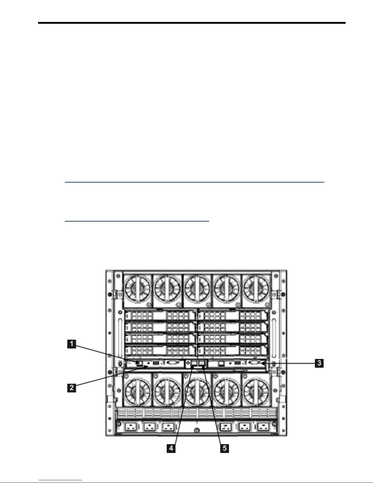
2 Ports and LEDs
All iLO 2 functions are available through the server MP LAN port and the local and remote serial
ports. On HP Integrity server blades, all iLO 2 functions are available on the Onboard
Administrator (OA). This chapter describes the available iLO 2 ports, connectors, and LEDs on
the HP Integrity server blades, and the rx2660, rx3600, and rx6600 servers.
HP Integrity Server Blade Components
Onboard Administrator (OA) is the enclosure management processor, subsystem, and firmware
base used to support the HP Integrity server blades and all the managed devices contained within
the enclosure. The OA provides a single point from which to perform basic management tasks
on server blades or switches within the enclosure. Using this hard-wired knowledge, the OA
performs initial configuration steps for the enclosure, enables runtime management and
configuration of the enclosure components, and informs you of problems within the enclosure
through email, SNMP, or the Insight Display.
Before setting up the HP BladeSystem OA, HP recommends that you read the HP BladeSystem
Onboard Administrator User Guide on the HP website at:
http://h20000.www2.hp.com/bc/docs/support/SupportManual/c00705292/c00705292.pdf
Reading this guide ensures that you understand the HP BladeSystem OA and that you properly
complete the initial setup to facilitate its proper functioning.
You can find other OA docs on the HP website at:
HP BladeSystem c-Class Onboard Administrator
Onboard Administrator
Figure 2-1 shows the OA/iLO network port and components.
Figure 2-1 OA/iLO Network Port and Components
HP Integrity Server Blade Components 31
Page 32
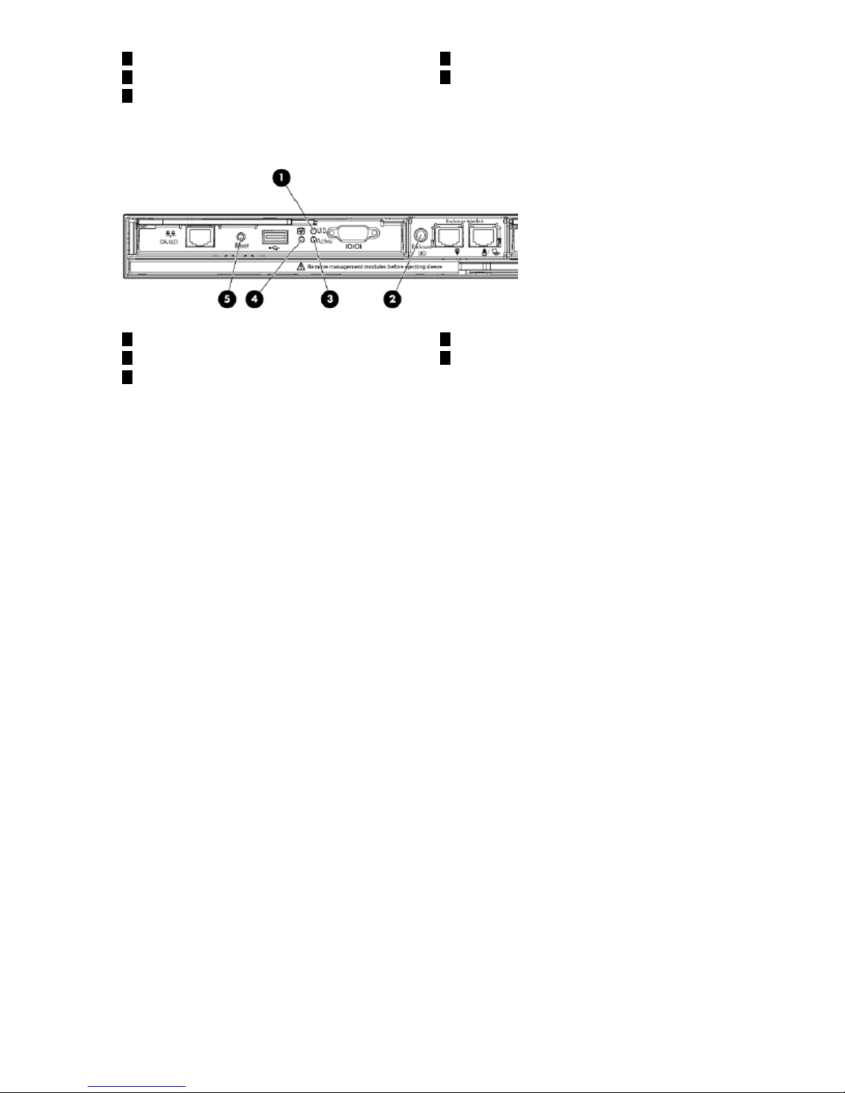
4
Enclosure Link-Up Port
1
OA/iLO Network Port
2
OA Bay 1
5
Enclosure Link-Down Port
3
OA Bay 2 (redundant if used)
Figure 2-2 shows the OA LEDs and buttons.
Figure 2-2 Onboard Administrator LEDs and Buttons
4
OA Health LED
1
OA UID LED
2
Enclosure UID LED
5
OA Reset Button
3
OA Active LED
32 Ports and LEDs
Page 33
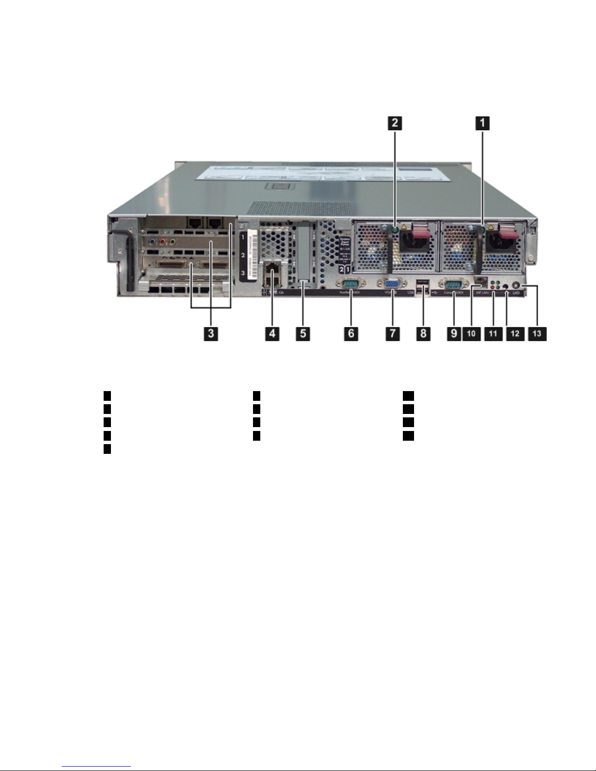
HP Integrity rx2660 Server Components
Figure 2-3 shows the rear view of the HP Integrity rx2660 server.
The system LAN functionality is integrated into the system board.
Figure 2-3 HP Integrity rx2660 Server Rear View
10
MP LAN Port
6
Auxiliary Serial Port
1
Power Supply 1 and LED
2
Power Supply 2 and LED
11
iLO 2 MP Status LEDs
7
VGA Port
8
USB Ports
3
PCI-x/PCIe Slots
12
iLO 2 MP Reset Button
1394
Core LAN Ports UID Button/LEDConsole Serial Port
(RS-232)
5
Smart Array P400
Controller Slot
HP Integrity rx3600 and rx6600 Server Components
Figure 2-4 shows the controls, ports, and LEDs on the rear of the HP Integrity rx3600 and rx6600
servers.
HP Integrity rx2660 Server Components 33
Page 34
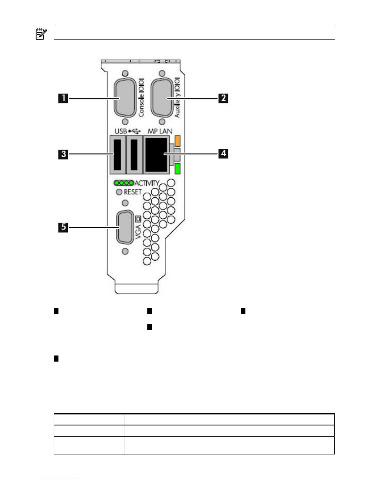
NOTE: This figure is oriented vertically to match the orientation of the core I/O board.
Figure 2-4 HP Integrity rx3600 and rx6600 Server Rear Ports and LEDs
53
USB 2.0 Ports (any USB
device)
1
iLO 2 MP Serial Console
Port (RS-232) (DB-9F to
VGA Port (No iLO 2 access;
EFI only)
DB-9F cable) connected to
4
MP LAN Port (10/100 LAN)
emulation terminal device
(PC, laptop, or ASCII
terminal)
2
General Use Serial Port
(Printers, etc.)
iLO 2 MP Status LEDs
Table 2-1 lists the state of the iLO 2 MP status LEDs during normal operation.
Table 2-1 iLO 2 MP Status LEDs
LED StateiLO 2 MP Status LED
Solid green.Standby Power
Off. The LED is solid amber when ac power is first applied. It remains solid amber for
a few seconds until the MP completes its self test; then the LED turns off.
iLO 2 MP Self Test
34 Ports and LEDs
Page 35

Table 2-1 iLO 2 MP Status LEDs (continued)
LED StateiLO 2 MP Status LED
Flashing green.iLO 2 MP Heartbeat
Flashing green.BMC Heartbeat
iLO 2 MP Reset Button
The iLO 2 MP Reset button enables you to reset iLO 2 and reset the user-specific values to factory
default values. A momentary press causes a soft reset of iLO 2 when the button is released. A
greater than four second press causes a soft reset of iLO 2 upon release and resets local user
accounts and passwords to factory default values.
Resetting Local User Accounts and Passwords to Default Values
If iLO 2 user passwords are lost, or iLO 2 local user accounts are disabled and logging in through
LDAP directory server is unsuccessful because the directory server is down or directory settings
have not been configured properly in LDAP command, you can reset local user accounts and
passwords to their default values.
To reset local user accounts and passwords to default values, follow these steps:
1. Connect a serial terminal (or serial-cabled laptop with serial emulation) to the console serial
port.
2. Press and hold the iLO 2 MP Reset button for more than four seconds. iLO 2 reboots to
factory default settings automatically.
3. Respond to the prompt to reset local user accounts and passwords to default values.
Console Serial Port and Auxiliary Serial Port
Figure 2-5 shows the console serial port connector with numbered labels for each pin on each
port.
Figure 2-5 Console Serial Port (RS-232) Connector
Table 2-2 maps the console serial port connector pin number to its signal description on each
port.
Table 2-2 Console Serial Port Pinouts
Signal DescriptionPin Number
Not used1
Receives data2
Transmits data3
Not used4
Ground5
Not used6
iLO 2 MP Reset Button 35
Page 36
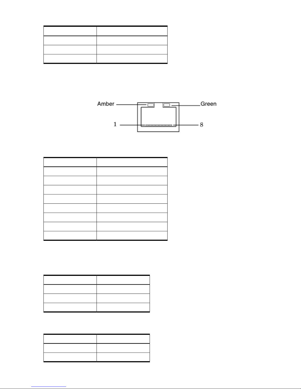
Table 2-2 Console Serial Port Pinouts (continued)
Signal DescriptionPin Number
Requests to send7
Clears to send8
Not used9
MP LAN Port
Figure 2-6 shows the MP LAN port connector pins and LEDs.
Figure 2-6 MP LAN Port
Table 2-3 maps the MP LAN port connector pin numbers to their signal descriptions.
Table 2-3 MP LAN Port Pinouts
Signal DescriptionPin Number
TXP1
TXN2
RXP3
Not used4
Not used5
RXN6
Not used7
Not used8
MP LAN LEDs
Table 2-4 lists the MP LAN link status LEDs and states.
Table 2-4 MP LAN Link Status LEDs
LED StateLink State
Blinking greenActivity
Solid greenLink with no activity
OffNo link
Table 2-5 lists the MP LAN link speed LEDs and states.
Table 2-5 MP LAN Link Speed LEDs
LED StateLink Speed
Solid amber100 Mb/s
Off10 Mb/s
36 Ports and LEDs
Page 37

3 Getting Connected to iLO 2
This chapter provides information on getting connected to iLO 2 through a rackmount server or
a server blade.
37
Page 38

Setup Checklist
Use the checklist in Table 3-1 to help set up iLO 2.
Table 3-1 Setup Checklist
XActionStep
Standard
For rackmount servers, perform steps 1 and 2. For server blades, see “Server Blade Connection” (page 45)
and continue with steps 3-8.
1. Determine the access method to select and connect
cables.
2. Determine the LAN configuration method and assign
an IP address if necessary.
3. Find and remove the iLO Network Information Tag.
This tag contains the default DNS name and iLO 2
login information. Removing the tag ensures
ventilation holes are kept clear for proper server
cooling.
Prepare1
Choose a method to configure the LAN for iLO 2 access:
• DHCP with DNS (Use the default DNS namesupplied
on your iLO Network Information Tag.)
• ARP Ping (This feature is supported on certain
Integrity serversto assign a static IP number to theMP
LAN.)
• Console serial port (RS-232) (You can perform all iLO
2 text commands from a serial console, or you can use
this interface to assign a static IP number, disconnect
the serial port, and resume from a web browser.)
Configure the MP LAN2
Log in to iLO 2 from
• a supported web browser if using DNS or static IP
• the TUI if using the console serial port
Use thedefault user name and password (Admin, Admin)
as found on your removable iLO Network Information
Tag.
Log in to iLO 23
Change the default user name and password on the
administrator account to your predefined selections.
Change default user name and
password
4
Set up the user accountsif you are using the local accounts
feature.
Set up user accounts5
Set up the security access settings.Set up security access6
Access the host console using your method of choice.Access the host console7
Advanced
• Integrity entry class
— Activate advanced features by entering your HP
Integrity Advanced Pack license key.
• Integrity server blades
— Ships with Advanced Pack license key factory
installed.
• Integrity mid range and Superdome
— Advanced features are enabled per hard partition
with installation of Lights-Out Advanced KVM
cards. No Advance Pack license key required.
Activate advanced features8
38 Getting Connected to iLO 2
Page 39
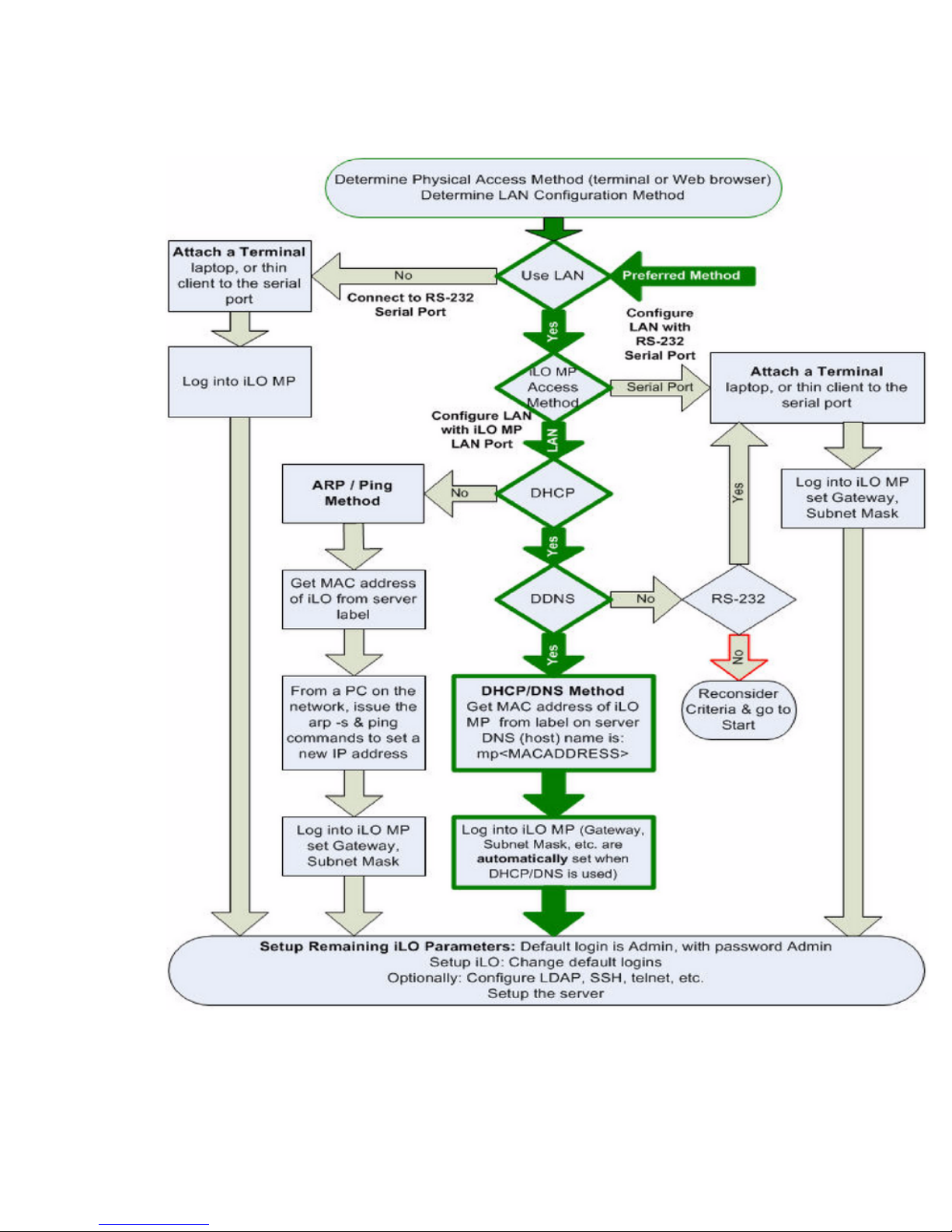
Setup Flowchart
Use this console setup flowchart as a guide to help set up the Integrity iLO 2.
Figure 3-1 Setup Flowchart
There are differences in how you connect to iLO 2 depending on if you have a rackmount server
or a server blade.
Setup Flowchart 39
Page 40
Rackmount Server Connection
For a rackmount server, you can connect directly through the serial console or you can connect
using the MP LAN.
To set up the console, follow these steps:
1. Determine the physical access method to connect cables. There are two physical connections
to iLO 2 :
• Console serial port (RS-232)
• MP LAN port
2. Assign an IP address to the iLO 2 MP LAN using one of the following methods:
• DHCP and DDNS. Though there are several methods to configuring the LAN, HP
recommends DHCP with DNS. DHCP with DNS comes preconfigured with default
factory settings, including a default user account and password. Use the DNS name on
the iLO Network Information Tag on the server.
To assign a static IP address instead of using DHCP, use one of the following methods:
• ARP Ping. This method can be used for Integrity entry class only.
• Console serial port (RS-232)
Preparing to Set Up iLO 2
Perform the following tasks before you configure the iLO 2 MP LAN:
• Determine the physical access method to select and connect cables.
• Determine the iLO 2 MP LAN configuration method and assign an IP address if necessary.
NOTE: Server blade iLO 2s are assigned an IP address by the blade chassis OA.
Determining the Physical iLO 2 Access Method
Before you can access iLO 2, you must determine the correct physical connection method.
There are several ways you can physically connect to iLO 2. Table 3-2 lists the appropriate
connection method, required connection components, and connectors to the host console.
Table 3-2 Physical Connection Matrix
Required Connection ComponentsConnection Method
• Host console
• Console serial port (RS-232) DB-9F to DB-9F cable (modem eliminator cable)
• Emulation terminal device (for example, a PC, laptop, or ASCII terminal)
These connection methods directly attach to the iLO 2 MP through the console serial port.
This is an RS-232 connection from a workstation to the server's iLO 2 MP console serial port.
Serial cable concentrators are used to provide switched access from one workstation to
multiple servers. Typically, the console serial port method is used by an administrator in the
data center.
Console serial port
(RS-232)
10/100 LAN cable
Remote access to the iLO 2 is a more convenient method. This remote access is through the
MP LANport. Depending on your LAN administration, thiscan be restricted to thedatacenter,
or extended outside the data center to your company's intranet.
The iLO 2 has a separate LAN port from the system LAN port. It requires a separate LAN
drop, IP address, and networking information from that of the operating system LAN port.
See Figure 2-3 and Figure 2-4 (page 34) and use Table 3-2 to determine your physical
connection method.
LAN port
40 Getting Connected to iLO 2
Page 41
Determining the iLO 2 MP LAN Configuration Method
To access iLO 2 through the MP LAN, iLO 2 must acquire an IP address. The way iLO 2 acquires
an IP address is dependent upon whether DHCP is enabled or disabled on the server, and if
DHCP and DNS services are available to the server (see Table 3-3).
Once you have determined theiLO 2 access method, you must determinehow youwill configure
the MP LAN in order to acquire an IP address using the following methods:
• DHCP/DNS through the management LAN (dynamically assigns an IP address): use the
DNS name on the iLO Network Information Tag on the server.
• Setting up a static IP address using a laptop with DHCP services and the management LAN.
• ARP Ping to set a static IP using a laptop and the management LAN (assigns a static IP
address to Integrity entry class only)
• Local RS-232 serial port and a serial console (assigns a static IP address).
Table 3-3 provides all the possible IP address acquisition scenarios. Use this table to help you
select the appropriate LAN configuration method to obtain an IP address.
Table 3-3 LAN Configuration Methods
LAN Configuration MethodConsole Serial Port (RS-232)DNSDHCP
DHCPNoYesYes
DHCP or console serial portYesYesYes
ARP Ping (entry class only)NoNoNo
ARP Ping (entry class only)NoYesNo
ARP Ping (entry class only); or console serial portYesYesNo
Console serial portYesNoYes
Console serial port or ARP Ping (entry class only)YesNoNo
Cannot set up the LAN; reconsider your criteriaNoNoYes
Configuring the iLO 2 MP LAN Using DHCP and DNS
DHCP automatically configures all DHCP-enabled servers with IP addresses, subnet masks, and
gateway addresses. All HP Integrity entry class servers with iLO 2 are shipped from the factory
with DHCP enabled.
HP recommends using the DHCP and DNS method to simplify access to iLO 2.
NOTE: You can use ARP Ping on entry class servers regardless of the status of DHCP unless
an IP address has ever been acquired using DHCP. Once an IP address is assigned using DHCP,
ARP Ping is permanently disabled.
When you use DHCP and DNS, you can connect to iLO 2 by entering the DNS name in your
browser rather than an IP address only if the following applies:
• DHCP must be enabled (DHCP is enabled by default).
• You are using a DHCP server that provides the domain name.
• The primary DNS server accepts dynamic DNS (DDNS) updates.
• The primary DNS server IP address was configured through the DHCP server.
IMPORTANT: You must know the DNS domain name, which is served out by the DHCP server,
unless its domain is local or the same domain.
To configure iLO 2 using DHCP and DNS, follow these steps:
Rackmount Server Connection 41
Page 42

1. Obtain the factory-set DNS name from the iLO Network Information Tag on the server. The
DNS name is 14 characters long. It consists of the letters MP followed by the 12 characters
of the MAC address. For example:
mp0014c29c064f
This address is assigned to the iLO 2 MP system board. The system board has a unique MAC
address that identifies the hardware on the network.
2. Connect the MP LAN cable from the server to an active network port.
3. Apply ac power to the server.
4. Open a browser, Telnet, or SSH client and enter the fully-qualified DNS name (the full path
name ending in the DNS name). The iLO 2 Log In window appears.
5. Log in using the default user name and password (Admin/Admin).
CAUTION: When DHCP is enabled, the system is vulnerable to security risks because anyone
can access iLO 2 until you change the default user name and password.
HP strongly recommends you assign user groups and rights before proceeding.
Configuring the iLO 2 MP LAN Using ARP Ping
This method can only be used for entry class.
NOTE: You can use ARP Ping regardless of the status of DHCP unless an IP address has ever
been acquiredusing DHCP. Once an IPaddress is assigned using DHCP, ARP Ping is permanently
disabled. Some DHCP server options can cause the apparent issuance of ARP Ping to iLO 2,
which negates the DHCP over DNS method.
The Address Resolution Protocol (ARP) and Packet Internet Grouper (Ping) utility uses ARP
packets to ping (discover) a device on the local network segment. The IP address you assign to
the server must use the same network segment (subnet) as the system assigning the address.
ARP does not work across routed or switched networks.
Use the ARP Ping utility to assign a static IP address when you do not have access to the console
serial port (RS-232) or when DHCP is not available.
ARP Ping has the following operational issues:
• The PC and the server must be on the same physical subnet.
• When a new server is first booted, DHCP is automatically available (factory-set default),
but ARP Ping does not start until three minutes after iLO 2 is booted. This applies to every
subsequent boot of iLO 2 until an IP address is obtained by DHCP or is assigned using the
LC command.
• Upon successfully assigning an IP address using ARP Ping, DHCP is automatically disabled.
Select one of the following methods to use the ARP Ping utility:
1. Connect a PC to the network that is on the same physical subnet as the server and run the
ARP Ping commands from the PC.
2. Locate an existing server on the network and log in to it.
3. Run the ARP Ping commands from the server.
Table 3-4 lists the ARP Ping commands.
42 Getting Connected to iLO 2
Page 43
Table 3-4 ARP Ping Commands
DescriptionARP Command
Assigns the IP address to the iLO 2 MP MAC address. This ARP table entry maps the MAC
address of the iLO 2 MP LAN interface to the static IP address designated for that interface.
arp -s
Tests network connections and verifies that the MP LAN port is configured with the appropriate
IP address.
ping
NOTE: The following procedure explains how to use the ARP Ping utility using a PC that is
connected to the network that is on the same physical subnet as the server.
To configure a static IP address using the ARP Ping utility, follow these steps:
1. Obtain the iLO 2 MP MAC address. To set the IP address using ARP, you must know the
MAC address of the iLO 2 MP LAN. You can find the MAC address of the iLO 2 MP LAN
on a label on the server.
IMPORTANT: Make sure you obtain the MAC address to the iLO 2 MP LAN and not the
MAC address to the server core LAN.
2. Verify that an active LAN cable on the local subnet is connected to the MP LAN port on the
server.
3. Access a PC on the same physical subnet as the server.
4. Open a DOS window on the PC.
5. At the DOS command prompt (C: >) , enter arp -s to assign the IP address to the iLO
MAC address.
The syntax is as follows:
arp -s <IP address you want to assign to the iLO MAC address> <iLO 2 MAC address>
Example from Windows
arp -s 255.255.255.0 00-00-0c-07-ac-00
6. At the DOS command prompt, enter ping followed by the IP address to verify that the MP
LAN port is configured with the appropriate IP address. The destination address is the IP
address that is mapped to the iLO MAC address. Perform this task from the PC that has the
ARP table entry.
The syntax is as follows:
ping <IP address just assigned to the iLO MAC address>
Example from Windows
ping 192.0.2.1
7. Use this IP address to connect to the iLO 2 MP LAN.
8. Use web or Telnet access to connect to iLO 2 from a host on the local subnet and configure
the rest of the LAN parameters (gateway, subnet).
Configuring the iLO 2 MP LAN Using the Console Serial Port
The terminal emulation device runs software that interfaces with the server. The software
emulates console output as it would appear on an ASCII terminal screen and displays it on a
console device screen.
To configure the iLO 2 MP LAN using the console serial port (RS-232), follow these steps:
Rackmount Server Connection 43
Page 44

IMPORTANT: Do not configure duplicate IP addresses on different servers within the same
network. The duplicate server IP addresses conflict and the servers cannot connect to the network.
The LC command enables you to configure a static IP address, host name, subnet mask, and
gateway address.
IMPORTANT: Ensure you have a console connection through the console serial port (RS-232)
or a network connection through the LAN to access the iLO 2 MP CLI and use the LC command.
1. Ensure the emulation software is correctly configured:
a. Verify that the communication settings are configured as follows:
• 8/none (parity)
• 9600 baud
• None (receive)
• None (transmit)
b. Verify that the terminal type is configured appropriately. The following are supported
terminal types:
• hpterm
• vt100
• vt100+
• vt-utf8
IMPORTANT: Do not mix hpterm and vt100 terminal types at the same time. If there
are two users collaborating and viewing console output with different emulation modes
set, their clients will see garbled results if the output from the system is terminal specific.
Consult the help section of the emulation software application for instructions on how to
configure the software options.
2. Use Table 3-2 to determine the required connectioncomponents and the ports used to connect
the server to the console device.
3. Connect the cables.
4. Start the emulation software on the console device.
5. Log in to iLO 2. See “Logging In to iLO 2 Using the Command Line Interface” (page 55).
6. At the MP Main Menu, enter CM and press Enter to select command mode.
7. At the command mode prompt, enter LS and press Enter. The screen displays the default
LAN configuration values. Write down the default values or log the information to a file.
8. To disable DHCP, enter the LC command.
a. From the LC command menu, enter D and press Enter.
b. Follow the instructions on the screen to change the DHCP status from enabled to
disabled.
c. Enter XD -R to reset iLO 2 (this is only necessary if you are connected through a serial
port).
9. Use the LC command to enter information for the IP address, host, subnet mask, gateway
parameters, and so on.
10. Enter XD -R -NC to reset iLO 2.
11. After iLO 2 resets, log in to iLO 2 again and enter CM at the MP> prompt.
12. To confirm that DHCP is disabled and display a list of updated LAN configuration settings,
enter the LS command.
44 Getting Connected to iLO 2
Page 45

NOTE: HP ProLiant servers allow you to assign a static IP address at boot time to iLO 2 using
a VGA monitor, keyboard, and mouse and HP ProLiant BIOS commands. This feature is not
available on HP Integrity servers.
Server Blade Connection
For a server blade, you can connect directly through the SUV cable to the serial console or you
can connect using the MP LAN internal connection in the blade enclosure.
NOTE: You do not cable up a separate MP LAN cable to each server blade.
In most circumstances, it is not necessary to physically connect to the iLO 2 on a Server Blade.
The iLO 2 on server blades typically use the MP LAN connection in the blade enclosure, and
typically get their LAN IP addresses assigned using the OA. In the rare cases where a physical
connection directly to a server blade iLO 2 is necessary, use one of the following methods:
• Connect to iLO 2 with DHCP enabled. Use the OA/iLO network port on the rear of the
enclosure. If the OA/iLO network port on the enclosure is connected to the local network
that has a DHCP server, your iLO 2 MP IP address is automatically generated by the DHCP
server. The server blade is factory set with DHCP enabled.
• Connect to iLO 2 with no network connection. Use the console serial port on the SUV cable.
If the enclosure is not connected to any network, you must configure your server through
the console serial port (RS-232) on the SUV cable.
NOTE: The local video port can be used to access the console at EFI or potentially the OS, but
is not a connection to iLO 2. The USB provides keyboard and mouse to the operating system on
HP Integrity server blades. Also, server blades do not support directly connecting a modem to
the MP (called the remote RS-232 port on servers), so there is no remote RS-232 connection on
the server blade. In addition, there is no LAN connection on the front of the server blade.
Connecting to a Server Blade iLO 2 Using the Console Serial Port
If the enclosure is not connected to any network, you must configure your server through the
console serial port (RS-232) on the SUV cable. Use this procedure to configure the console serial
port to enable iLO 2 access. To perform this procedure, you need a terminal emulator (for example,
a laptop using hyperterm) to connect to the server blade.
Server Blade Connection 45
Page 46
NOTE: On the HP Integrity server blades, you have access to two serial ports through the
RS-232 connector. The default setting is for the iLO 2 interface, the other is for an AUX UART
directly connected to the host operating system and can be used for any serial device (terminal,
debug port, and so on). HP recommends using the AUX UART for server blade setup and debug
purposes only.
You can use a command to toggle between the two ports. However, if access to the iLO 2 MP
TUI CLI is not possible through Telnet and if the port mode of operation is set to the AUX UART,
perform a hard reset of iLO 2 to set it to the default shipping settings. To perform a hard reset,
push the recessed MP Reset button.
TIP: It is not necessary to physically connect to iLO 2 through the console serial port to perform
management tasks. Use the OA/iLO 2 LAN port to communicate with any iLO 2 in the enclosure
and the OA. You can use the LCD panel and the OA to configure and determine the iLO 2 MP
LAN address.
Connecting the SUV Cable to the Server Blade
This section describes how to connect your server blade to a terminal device using the SUV port.
CAUTION: Disconnect the SUV cable fromthe port when it is not in use.The port and connector
are not intended to provide a permanent connection as it may block proper air flow if left attached
for extended periods.
On the SUV cable, locking buttons are located on the sides of the server blade connector. Always
squeeze the locking buttons on the SUV cable connector before disconnecting the SUV cable from
the SUV cable port. Failure to do so can result in damage to the port.
Use caution when walking near the server blade when the SUV cable is installed. Hitting or
bumping the cable can cause the port on the server blade to break. This can damage the system
board, requiring it to be replaced.
To establish a connection from the server blade to the terminal emulator, follow these steps:
1. Insert the SUV cable into the SUV port on the rear of the server blade. See Figure 3-2 and
Figure 3-3.
2. Connect a standard DB-9F to DB-9F modem eliminator cable to the RS-232 port on the SUV
cable.
3. Connect the other end of the DB-9F to DB-9F modem eliminator cable to the terminal
emulator.
4. Verify the parameters for serial console port communication are set to the following values
on your terminal or emulator device:
• VT 100 protocol
• 8/none (parity)
• 9600 baud
• None (receive)
• None (transmit)
5. To set the parameters, click OK.
6. If running an emulator, launch it now.
46 Getting Connected to iLO 2
Page 47
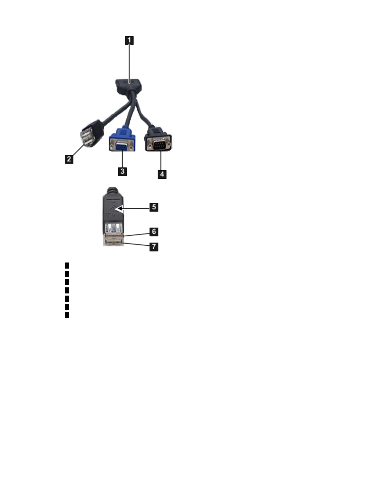
Figure 3-2 SUV Cable
1
Server Blade Connector
2
2-Port USB
3
VGA (no access to iLO 2)
4
9-Pin Console Serial Port (RS-232)
5
USB Label
6
USB-1
7
USB-0
Server Blade Connection 47
Page 48

Figure 3-3 Connecting the SUV Cable To the Server Blade
Connecting the Server Blade To iLO 2 Using the Onboard Administrator
If the OA/iLO network port on the enclosure is connected to the local network that has a DHCP
server, your iLO 2 MP IP address is automatically generated by the DHCP server. The server
blade is factory set with DHCP enabled.
For complete OA information, the following guides can be found on the HP website:
• For CLI, see the HP BladeSystem Onboard Administrator Command Line Interface User Guide.
• For web GUI, see the HP BladeSystem Onboard Administrator User Guide.
To connect to iLO 2 using the OA, follow these steps:
1. Connect a standard LAN cable to the OA/iLO network port on the rear of the server blade.
2. Connect the LAN cable to a local network that has a DHCP server. The LCD display panel
on the front of the enclosure displays the Main Menu.
3. Select Blade or Port Info from the options and click OK.
4. Select the appropriate server blade from the options on the screen and click OK. The screen
displays the iLO 2 MP IP address.
5. Write down the iLO 2 MP IP address.
6. Access iLO 2 through Telnet, SSH, or the web using the assigned DHCP iLO 2 MP IP address.
48 Getting Connected to iLO 2
Page 49

NOTE: For the HP Integrity server blades, you can use the OA to set the IP addresses for all
iLO 2s. You can also find the iLO 2 MP address so you can log in.
IMPORTANT: Integrity iLO 2 must have a reachable IP address as the default gateway address.
Since the OA is always reachable, HP recommends using the OA IP address as the gateway
address for Integrity iLO 2. If you use the Enclosure IP mode, this solution works during a
failover. In the Enclosure IP mode, a static IP address is assigned to the active OA, and during
a failover, the same IP address follows the active OA. If the OA IP address is assigned using
DHCP, the solution does not work. In such instances, HP recommends manually changing the
iLO 2 gateway address.
Auto Login
Auto login provides direct access to iLO 2 from the OA for users who already logged in to the
OA. A user who has authenticated their connection to the OA can follow a link to a server blade
in the enclosure without an additional login step. Auto login features and usage are as follows:
• A user who has authenticated a connection to the OA is able to establish a connection with
iLO 2 without providing the user login and password to iLO 2.
• The OA provides the following auto login connection methods to iLO 2 links to users to
launch these connections to iLO 2:
iLO CLI SSH Connection If you logged in to the OA CLI through SSH, enter
connect server <bay number> to establish an
SSH/Telnet connection with iLO 2.
iLO Web GUI Connection If you logged in to the OA web GUI, click on the link to
launch the iLO web GUI.
• Auto login is implemented using IPMI commands over I2C between the OA and iLO 2 to
create and delete user commands.
• Supports a maximum of four simultaneous OA user accounts. The OA keeps track of these
users locally. The information maintained for each user is the user name, password, and
privilege levels.
• User accounts for the auto login feature are created in the MP database when an auto login
session is established. These accounts are deleted when the auto login session is terminated.
• If a maximum number of user accounts has already been reached, and the OA creates another
account on iLO 2. The OA sends a request to iLO 2 to delete one of the previously created
accounts, before attempting to create a new one.
• If iLO 2 is rebooted or power-cycled, it checks if there are any previously created OA user
accounts in the iLO 2 user database when it boots up. If there are any previously-created
OA user accounts, it deletes those accounts.
• View and manage user accounts created in iLO 2 by the OA like any other local user account
on iLO 2. To view and manage user accounts, use the TUI WHO, UC commands; or use the
User Administration Page in the web GUI.
• View and disconnect user connections established through the auto login feature just like
other connections to iLO 2. To view and disconnect user connections, use the TUI WHO, DI
commands, or use the User Administration Page in the web GUI.
• The OA supports three types of users: administrators,operators, and users. These user types
map to the following iLO 2 capabilities:
Administrators Can perform any function including iLO 2 MP configuration. This
level equates to an iLO 2 user with all privilege levels such as,
Administer User Accounts, Remote Console Access, Virtual Power
and Reset, Virtual Media, and Configure iLO MP settings. It allows
Server Blade Connection 49
Page 50

access to all aspects of the OA including configuration, firmware
updates, user management, and resetting default settings.
Operators Provided access to the host system IRC, serial console, and vMedia.
This level equates to an iLO 2 user with Remote Console Access,
Virtual Power and Reset, Virtual Media, and Configure iLO settings.
It allows access to all but configuration changes and user
management. This account is used for individuals who might be
required to periodically change configuration settings.
Users Provided read-only login access to iLO 2. This account is used for
individuals who need to see the configuration of the OA but do not
need the ability to change settings. This level equates to an iLO 2user
with no privileges set.
NOTE: For information on how to set user roles and privilege levels in the OA, see the HP
BladeSystem Onboard Administrator User Guide.
Initiating an Auto Login Session
The auto login session is initiated as follows:
1. The OA finds the first available auto login user by finding the first user entry with a
time-created value of 0.(OAtmp1...OAtmp4).
2. If there are no available users, the oldest user is deleted.
NOTE: This could terminate a currently active session.
a. The OA sends a request to iLO 2 to delete that user.
3. The OA sends a command to create an OA user.
4. The OA launches an SSH or web GUI connection to iLO 2 and logs in with created user’s
credentials.
Terminating an Auto Login Session
When the auto login CLI or web GUI session is terminated, the following user clean up is
performed:
• For auto login sessions, the temporary Auto Login iLO 2 account is deleted when the session
with the iLO 2 is terminated.
User Account Cleanup During IPF Blade Initialization
During an IPF blade initialization, the OA and iLO 2 perform the following:
• When a server blade is inserted, or iLO 2 or the OA is reboot or reset, both the OA and iLO
2 perform cleanup of the accounts that could have been created for auto login before the
reset.
• When iLO 2 initializes, the OA marks all four user slots as unused.
• Integrity iLO 2 scans its local user accounts. If there are any OA created user accounts, they
are deleted from the iLO 2 user database.
Auto Login Troubleshooting
There may be times when auto login fails. The following information provides possible reasons
for the failure
50 Getting Connected to iLO 2
Page 51

User Creation When the OA sends a request to iLO 2 to create a new user, iLO 2 attempts
to create a user in the local iLO 2 user database. Creation of an OA user
could fail for a number of reasons:
• The local user database is disabled in iLO 2 and LDAP authentication
is being used.
• The iLO 2 user database has reached the maximum number of users
(19 users).
• There is already a user registered with the same login name.
User Login After an OA user has been created in the iLO 2 database, the OA user login
can still fail for a number of reasons:
• The iLO 2 upgrade is currently in progress, and no new connections
are allowed.
• Maximum number of connections for the requested connection type
(SSH, Telnet, web GUI) to iLO 2 has been reached.
• Requested connection type (SSH, Telnet or web) to iLO 2 is currently
disabled.
User Deletion When the OA sends a request to iLO 2 to delete a user, iLO 2 attempts to
delete that user from the local iLO 2 user database. Deletion of an OA user
could fail for a number of reasons:
• A user with the specified login does not exist (user could have been
deleted through other iLO 2 user interface).
• The specified user cannot be deleted because it is the only user in the
local database with user administration right.
Additional Setup
This section provides additional information to set up iLO 2.
Modifying User Accounts and Default Passwords
Integrity iLO 2 comes preconfigured with default factory settings, including a default user account
and password. The two default user accounts on initial login are:
• All Rights (Administrator) level user:
login = Admin
password = Admin
• Console Rights (Operator) level user:
login = Oper
password = Oper
Login and password are case sensitive.
TIP: For security reasons, HP strongly recommends you modify the default settings during the
initial login session.
Make the following changes using any of the iLO 2 user interfaces.
To modify default account configuration settings, follow these steps:
1. Log in as the administrator to modify default user configuration settings
2. To modify default passwords, follow these steps:
Additional Setup 51
Page 52

a. Access the MP Main Menu.
b. Enter CM at the MP> prompt.
c. Enter UC at the MP:CM> prompt and follow the prompts to modify default passwords.
3. To set up user accounts, follow these steps:
a. Access the MP Main Menu.
b. Enter CM at the MP> prompt.
c. Enter UC at the MP:CM> prompt and follow the prompts to modify user accounts.
Setting Up Security
For greater security and reliability, HP recommends that iLO 2 management traffic be on a
separate dedicated management network and that only administrators be granted access to that
network. This not only improves performance by reducing traffic load across the main network,
it also acts as the first line of defense against security attacks. A separate network enables you
to physically control which workstations are connected to the network.
Setting Security Access
Determine the security access required and what user accounts and privileges are needed. iLO
2 provides options to control user access. Select one of the following options to prevent
unauthorized access to iLO 2:
• Change the default user name and password. See “Modifying User Accounts and Default
Passwords” (page 51).
CAUTION: When DHCP is enabled, the system is vulnerable to security risks because
anyone can access iLO 2 until you change the default user name and password.
HP strongly recommends you assign user groups and rights before proceeding.
• Create local accounts. You can store up to 19 user names and passwords to manage iLO 2
access. This is ideal for small environments such as labs and small-to-medium sized
businesses.
• Use corporate directory services to manage iLO 2 user access. This is ideal for environments
with a large number of frequently changing users. If you plan to use directory services, HP
recommends leaving at least one local account enabled as an alternate method of access.
For more information on how to create local accounts and use directory services, see Chapter 9:
“Installing and Configuring Directory Services ” (page 179).
Setting iLO 2 MP LAN From EFI
Integrity iLO 2 supports an EFI utility to view or configure the iLO 2 MP LAN parameters. If the
parameters have not been previously configured, you can use this utility to set them from EFI.
To view the iLO 2 MP LAN parameters from EFI, follow these steps:
1. Boot to the EFI Shell.
2. Run ilosetup.efi from EFI.
fs0:\EFI\TOOLS> ilosetup get
Current LAN parameters:
IP Address : 15.255.96.44
Subnet : 255.255.248.0
Gateway : 15.255.96.1
To configure the iLO 2 MP LAN parameters from EFI, follow these steps:
1. Boot to the EFI Shell.
52 Getting Connected to iLO 2
Page 53

2. Run ilosetup.efi from EFI.
fs0:\EFI\TOOLS> ilosetup get
Current LAN parameters:
IP Address : 127.0.0.1
Subnet : 255.255.255.0
Gateway : 127.0.0.1
fs0:\EFI\TOOLS>
fs0:\EFI\TOOLS> ilosetup set -l -i 15.255.96.44 -g 15.255.96.1 -s 255.255.248.0
Attemping to set iLO LAN parameters...
LAN parameters have been set.
The iLO2 resets after you have successfully configured the LAN parameters.
Additional Setup 53
Page 54

54
Page 55

4 Logging In to iLO 2
This chapter provides instructions on how to log in to iLO 2.
Integrity iLO 2 standard features provide basic system board management functions, diagnostics,
and essential Lights-Out functionality on iLO 2-supported HP servers. For a list of the standard
features, see “Standard Features” (page 22).
Logging In to iLO 2 Using the Web GUI
To log in to iLO 2 using the web GUI, follow these steps:
1. Open a web browser and enter the DNS name or the IP address for the iLO 2.
2. Log in using the default iLO 2 user name and password (Admin/Admin).
TIP: For security reasons, HP strongly recommends you modify the default settings during
the initial login session. See “Modifying User Accounts and Default Passwords” (page 51).
Logging In to iLO 2 Using the Command Line Interface
To log in to the iLO 2 command line interface, follow these steps:
1. Access iLO 2 using the console serial port (RS-232), or enter through the LAN, using Telnet,
SSH, or console emulation method. The iLO 2 MP login prompt appears.
2. Log in using the default the iLO 2 user name and password (Admin/Admin).
TIP: For security reasons, HP strongly recommends you modify the default settings during
the initial login session. See “Modifying User Accounts and Default Passwords” (page 51).
Following is the MP Main Menu:
CO: Console
VFP: Virtual Front Panel
CM: Command Menu
CL: Console Logs
SL: Show Event Logs
SMCLP: Server Management Command Line Protocol
HE: Main Menu Help
X: Exit Connection
See Section : “Text User Interface” (page 83) for information on the iLO 2 MP menus and
commands.
TIP: When logging in using the local or remote console serial ports, the login prompt may not
display if another user is logged in through these ports. In this case, use Ctrl-B to access the MP
Main Menu and the MP> prompt.
Network Port Usage
The open network ports iLO 2 uses are listed in the following tables. Table 4-1 lists the TCP ports
and Table 4-2 lists the UDP ports.
Logging In to iLO 2 Using the Web GUI 55
Page 56

Table 4-1 TCP Ports
Port FunctionalityPort TypePort Identifier
This is the default port used by clients connecting to iLO 2 using SSH
protocol.
SSH portPort 22
This is the default port used by clients connecting to iLO 2 using
Telnet protocol.
Telnet portPort 23
This is the default port used by clients connecting to iLO 2 using the
web interface or a web browser. This port is not secure. This port
provides basic iLO 2 identification information when queried. Any
web connectionmade on port 80 is redirected to the login on the https
port for a secure web session.
http portPort 80
This is the port used by clients connecting to iLO 2 using the web
interface or a web browser securely. This is a secure port.
https portPort 443
Clients connect to this port by default when using the Remote Serial
Console connection.
remote serial console
port
Port 2023
Clients connectto this port when usingthe Integrated Remote Console
connection.
vKVM portPort 4644
Clients connect to this port when using the Virtual Media applet
connection.
vMedia portPort 17988
Table 4-2 UDP Ports
Port FunctionalityPort Number
This port is used by clients to query SNMP information from iLO 2.Port 161
This port is used by clients to issue IPMI commands to iLO 2.Port 623
56 Logging In to iLO 2
Page 57

5 Adding Advanced Features
Integrity iLO 2 advanced features are enabled on Integrity servers in one of two ways.
• For Integrity entry class and server blades, the advanced features are enabled with a license
key.
• For Integrity cell-based servers, the advanced features are enabled with a PCI-X accessory
card instead of a key.
For a description of the iLO 2 advanced features and information on how to add advanced
features, see “Advanced Features” (page 25).
Lights-Out Advanced KVM Card for sx2000 Servers
The HP Lights-Out Advanced KVM card is a PCI-X card that you install into any sx2000-based
mid range or high end HP Integrity server such as rx7640, rx8640, and Superdome sx2000.
The card works in conjunction with the iLO 2 management processor built into your server and
enables the iLO 2 management processor and web GUI interface to access the IRC and vMedia
in each hard partition (nPar).
The iLO 2 communicates with the Lights-Out Advanced KVM card over an internal system bus.
The card has an external management LAN port which must be connected externally to the same
subnet as theiLO 2 MP LAN. The Lights-Out Advanced KVM card uses this LAN port to provide
IRC and vMedia communication with the remote user.
The card offers physical video functionality (VGA) for servers running Windows, and USB
functionality for servers running HP-UX, Windows, and OpenVMS.
This Lights-Out Advanced KVM card (AD307A) is a superset of the previous graphics/USB card
(A6869A or A6869B). The AD307A card should be used instead of A6869A or A6869B cards.
TIP: The AD307A is not “iLO on a card”. It is not like the ProLiant Lights-Out 100 cards, or
RILO cards. The AD307A is a card that adds the logic and firmware to enable the Lights-Out
Advanced features of vMedia and the IRC. This card works by extending the features of the iLO2
of the main chassis. This card does not require any additional license keys (no “Advanced Pack
license”).
You must install one card in each hard partition (nPar) where the Lights-Out Advanced features
are required. You can assign an IP number to the Lights-Out Advanced KVM card through the
iLO 2 web GUI or the MP command line interface. The Lights-Out Advanced KVM card features
are presented to you through the main iLO 2 interfaces.
IMPORTANT: Lights-Out Advanced features are fully enabled on the Lights-Out Advanced
KVM card. You do not need to purchase an additional “advanced pack” license to access the
functionality.
The Lights-Out Advanced KVM card offers the following features:
• Provides extra features for flexibility and manageability of sx2000-based Integrity servers
for both remote management when being physically in the datacenter is inconvenient or
impractical; and management while in the datacenter.
• The Lights-Out Advanced KVM card enables the advanced IRC and virtual CD/DVD/ISO
image file (vMedia) features of iLO 2.
— Load software from a DVD using vMedia instead of making a trip to the datacenter.
— IRC enables full VGA graphical console support remotely.
— View the Windows console or Windows boot process with the IRC instead of a crash
cart (monitor, keyboard).
Lights-Out Advanced KVM Card for sx2000 Servers 57
Page 58

— vMedia enables remote attachment of a USB read-only CD or DVD storage device, or
ISO file image, including support for bootable media.
— Use vMedia to easily upgrade firmware on npars.
— Create an ISO file of a vfat file system with the required files
◦ Start vMedia, present .iso file to npar, boot to EFI, go to the fsX: that corresponds
to the vMedia, run e.g. update.nsh and repeat on next partition
— For Windows, you can do installs remotely without having to cable up the VGA/USB
card to an IP console switch or a physical monitor, keyboard, and mouse.
• Integrated VGA graphics and USB ports offer flexibility in the datacenter to monitor a system
with full KVM functionality from boot, to desktop, to shutdown.
• Easily accessed through the iLO 2 web GUI.
Additional Lights-Out Advanced KVM card Information
HP Lights-Out Advanced KVM Card for sx2000 Servers White Paper on the HP website at:
http://docs.hp.com/en/AD307-90001/AD307-90001.pdf
You can read about the Lights-Out Advanced KVM card on the HP website at:
http://www.hp.com/go/integrityilo
You can read the Quick Specs on the HP website at:
http://h18000.www1.hp.com/products/quickspecs/12602_na/12602_na.HTML
You can read an example of ordering and configuration information on the HP website at:
http://ccesalewspr02.cce.hp.com/docfiles/V7%20Content/KGNew/6158816/c00430232.pdf
Lights-Out Advanced KVM card Requirements
This sectionaddresses the following Lights-Out Advanced KVM card requirements and conditions:
• You need Java on the browser system to use vMedia.
• You need Internet Explorer Active-X controls to use the IRC.
• Internet Explorer 6.0 SP1 (minimum) is required for the IRC.
• You need to be running Internet Explorer (with Active-X) on the browser system to use the
IRC. Currently, IRC only supports partitions running Windows.
• You can only launch one vMedia per complex. For example, if you have vMedia running
for nPar1, you cannot run vMedia for nPar2.
• A network link to the partition's Lights-Out Advanced KVM card is required to launch
vMedia. If there is no network link, the following message displays Status: vMedia is
in use or unavailable.
• Vista client systems are not currently supported. You can still run your SSH and Telnet
sessions to the MP for VFP, character console, and streaming live system event logs.
Table 5-1 lists the supported system configurations for the Lights-Out Advanced KVM card at
the time this document was written. For the most recent product specifications, see
www.hp.com/go/integrityilo.
58 Adding Advanced Features
Page 59

Table 5-1 Supported System Configurations
DescriptionSystem Component
• Microsoft Windows Server 2003
• HP-UX 11i v2 or later
• OpenVMS Version 8.3 or later
• Windows 2008
nPartition operating system
• rx7640
• rx8640
• Superdome sx2000
Supported platforms
You can install the Lights-Out Advanced KVM card on any sx2000-based Integrity server with
updated management processor firmware that provides iLO 2 functionality and uses the web
interface to access iLO 2. The Lights-Out Advanced KVM card must be installed in a PCI-X
mode-1 slot. It cannot be used in PCI-X mode 2 slots or in PCIe slots. To determine which slots
are mode-1 compatible, see the documentation for your server product. A Lights-Out Advanced
KVM card is required for each hard partition (nPartition) where you want virtual keyboard,
video, mouse (vKVM) and vMedia functionality; Lights-Out Advanced functionality is not
currently supported on virtual partitions (vPar).
TIP: Remember, you do not need an iLO 2 Advanced Pack license key to use this card.
Table 5-2 lists which features of the Lights-Out Advanced KVM card are available on each
operating system.
Table 5-2 Availability of Features
USB PortsVGA Graphics PortvMedia
IRC
1
nPartition Operating System
YesYesYesYesWindows
YesNoYesNoHP-UX
YesNoYesNoOpenVMS
Not currently supported under Linux.Linux
1 The remote management workstation must be running Windows with Active-X enabled on Internet Explorer 7.
Configuring the Lights-Out Advanced KVM Card
Usually, the Lights-Out Advanced KVM card obtains its IP address automatically from a DHCP
server. Ifyou do not have a DHCP server on your network, you must manually set the Lights-Out
Lights-Out Advanced KVM Card for sx2000 Servers 59
Page 60
Advanced KVM card IP address. To manually set the Lights-Out Advanced KVM card IP address,
follow these steps:
• If you are using the web GUI, use the LAN Settings page on the Administration tab.
• If you are using the MP CLI, use the LC command.
— MP:CM> lc
MP Configurable LAN devices:
1. MP Customer LAN
2. Integrity LO Advanced KVM Card: Cab 0, IO Chas 1, Slot 7
3. Enter LAN device to change, or [Q] to Quit:
NOTE: If the Lights-Out Advanced KVM card IP settings are not configured, the card still
works as a local VGA/USB card, but IRC and vMedia do not work.
NOTE: Before the LC command allows you to configure an IP address, you must boot the
system to EFI so the Lights-Out Advanced KVM card can be detected by system firmware.
TIP: You never need to connect serial cables to the Lights-Out Advanced KVM card. The
Lights-Out Advanced KVM card communicates to iLO 2 through an internal bus.
Lights-Out Advanced KVM Card IRC Feature
The iLO 2 MP that is built into your server provides, as a standard feature, a virtual serial console
where you can view the entire managed server in the standard HP-UX, Linux, OpenVMS, or
Windows headless console format. The IRC feature of the Lights-Out Advanced KVM card
enables you to view video output from the managed OS hard partition (nPartition) where the
Lights-Out Advanced KVM card is installed, providing a seamless view from the server boot to
OS desktop.
The Lights-Out Advanced hardware captures three essential components for the managed (host)
nPartition:
• Keyboard input to the console
• Video output
• Mouse input to the console
When a user activates the remote console on the Windows management workstation, the
Lights-Out Advanced KVM card sends all keyboard and mouse input from the IRC / vKVM
client to the host nPartition.
For information on how to use the IRC, see “Integrated Remote Console” (page 119).
Lights-Out Advanced KVM Card vMedia Feature
Virtual Media support, which ispart of the Lights-Out Advanced KVM card feature set, provides
users with a virtual disk drive that connects to the managed server through the same management
LAN as the iLO/MP, just as if it were physically connected to the server.
The Lights-Out Advanced KVM card uses a client-server model to perform vMedia functions.
The Lights-Out Advanced KVM card streams virtual media data across a live network connection
between the remote management console and the host server. The virtual media Java applet
provides data to the Lights-Out Advanced KVM card as it is requested.
The Lights-Out Advanced KVM card contains a USB device that is viewed by the host OS as if
it were a physical USB device connected to the server. Under the control of the Lights-Out
Advanced KVM card firmware, a virtual USB device can be remotely connected to the host
server. When the virtual media is connected, an OS that is USB-aware loads its standard USB
60 Adding Advanced Features
Page 61
mass storage driver. Once the USB mass storage driver is loaded, the server OS does not require
additional HP drivers running on the server OS.
Additionally, the host server EFI system firmware is extended to support USB virtual devices,
making virtual media available end-to-end (in a pre-boot environment, through OS loading and
while the OS is operational).
NOTE: The Lights-Out Advanced KVM card must be connected to the same subnet as the MP
LAN to enable vKVM and vMedia functionality.
For information on how to use vMedia, see “Virtual Media” (page 125).
Installing the Lights-Out Advanced KVM Card in a Server
You can install the HP Lights-Out Advanced KVM card into any mode-1 slot in a PCI-X backplane,
or any mode-1 PCI-X slot in a PCI-X/PCIe backplane.
CAUTION: Observe all electrostatic discharge (ESD) safety precautions before attempting this
procedure. Failure to follow ESD safety precautions could cause damage to the server.
CAUTION: You cannot add or replace a Lights-Out Advanced KVM card while the nPartition
is running. You must first shut down the nPartition before adding or replacing the card. For
more information on shutting down nPartitions and powering off hardware components, see
your server documentation.
IMPORTANT: The HP Lights-Out Advanced KVM card requires that your server has the
minimum system firmware installed. To see the firmware versions, go to the HP website at
www.hp.com/go/integrityilo.
Before performing certain iLO 2 functions, verify that you have the supported firmware version
required to carry out the task.
Lights-Out Advanced KVM Card for sx2000 Servers 61
Page 62
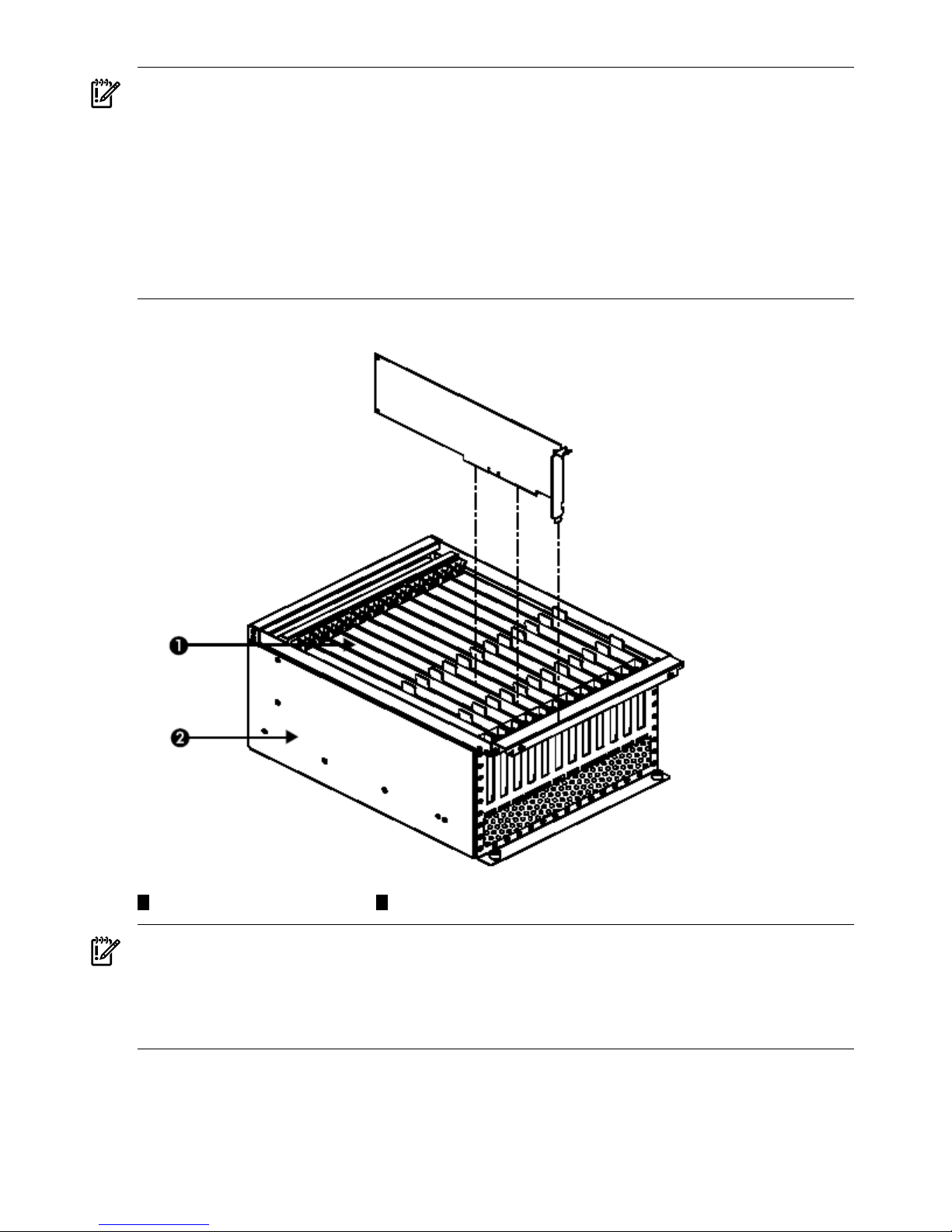
IMPORTANT: The HP Integrity rx8640 and rx7640 midrange servers supportonly one Lights-Out
Advanced KVM card per partition, and the card must be installed in an I/O chassis with a core
I/O card installed. If you install multiple Lights-Out Advanced KVM cards on one partition, only
the first card that is detected is fully enabled. Subsequent cards will have only USB functionality
enabled.
IMPORTANT: The graphics functionality of the Lights-Out Advanced KVM card also takes
precedence over the A6869B graphics/USB PCI card. If both a Lights-Out Advanced KVM card
and an A6869B card are present on a partition, the A6869B card has only USB functionality
enabled. HP recommends removing the A6869B card if you have both cards installed on a
partition.
Figure 5-1 PCI-X or PCI-X/PCIe Card Cage (Common to all supported servers)
21
PCI-X or PCIe BackplanePCI-X/PCIe Cards
IMPORTANT: Cabling requirements:
• You must connect the LAN port on the Lights-Out Advanced KVM card to the same network
as the MP LAN port on the server.
• You need a network cable to your regular core I/O MP port - one per complex.
• You need one network cable to each Lights-Out Advanced KVM card.
To install the Lights-Out Advanced KVM card, perform the following steps:
1. Shut down the nPartition and power-off the appropriate PCI power domain.
2. Locate an empty mode-1 PCI-X slot where the card will be installed.
62 Adding Advanced Features
Page 63
3. Position the card over the empty slot, ensuring that the edge connector keyways match on
the PCI-X or PCI-X/PCIe backplane connector.
4. Using slow, firm pressure, seat the card in the slot.
5. Connect the management LAN cable to the LAN port on the card.
NOTE: If you do not wish to use the on-card KVM features, ignore steps 6 and 7, and
proceed to step 8.
6. Connect the monitor cable to the VGA port on the card, and connect the mouse and keyboard
cables to the USB ports on the card.
7. Connect the monitor power cable, and then turn on the monitor.
8. Power on the PCI power domain, and then boot the nPartition.
By default,the Lights-Out Advanced KVM card uses Dynamic Host Control Protocol(DHCP)
to obtain an IP address. Alternatively, you can assign a static IP address to the Lights-Out
Advanced KVM card through a menu in the main iLO 2 web GUI interface or other iLO 2
MP command line.
To remove the Lights-Out Advanced KVM card, reverse these steps.
Lights-Out Advanced KVM Card Quick Setup Steps
To perform a quick setup of the Integrity Lights-Out Advanced KVM card for vMedia and the
IRC, follow these steps:
1. Plug the LAN cable into the MP of the core I/O card for the complex.
2. Plug the LAN cable into the LAN slot of the Lights-Out Advanced KVM card for each nPar.
NOTE: Usually, the Lights-Out Advanced KVM card obtains its IP address automatically
from a DHCP server. If you do not have a DHCP server on your network, you must manually
set theLights-Out Advanced KVM card IP address. To manually set the Lights-Out Advanced
KVM card IP address, see “Configuring the Lights-Out Advanced KVM Card” (page 59)
3. Browse to iLO 2 (MP) and login.
a. -> Administration -> Network Settings -> Device to modify: <npar> KVM
b. -> assign a network address (DHCP or static) -> Submit.
NOTE: You may also need to set up the Domain Name Server if you are not using
DHCP.
4. Check the status of vMedia availability.
a. Virtual Media -> select partition: <npar name> -> (check status directly under “select
partition status” ) it should read “Status: vMedia is available”.
• If not, there may not be network connectivity to the Lights-Out Advanced KVM
card – check this with ARP ping.
• If the network is OK, check that another vMedia window for this complex is not
open somewhere.
NOTE: Only one vMedia window is shared among all the npars in the complex.
b. If this fails, log out of iLO 2 and log back in again.
5. Once the vMedia window opens, select Local Image File.
6. Browse to the iso file and click Connect.
Lights-Out Advanced KVM Card for sx2000 Servers 63
Page 64
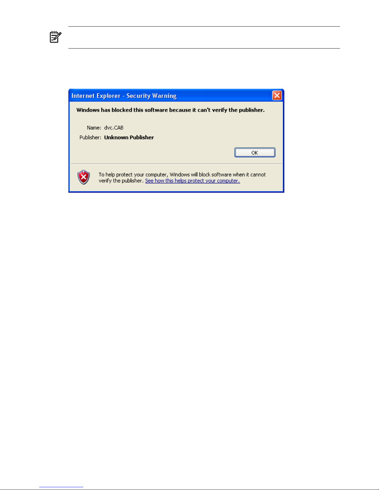
NOTE: The IRC is only supported on Windows systems. You can only open one IRC session
at a time with one iLO 2 web GUI session.
7. If not yet done, go to the EFI Shell: acpiconfig windows and reset.
8. Start the IRC. If you get the following “dvc.cab unknown publisher” error:
Figure 5-2 dvc.CAB Error
Follow these steps:
a. Close the IRC window.
b. Open a vMedia window for that npar (no need to connect).
c. Select Always trust content from this publisher in the Warning - Security
window after opening vMedia.
d. Re-open the IRC window.
9. When rebooting. you should see the output of the console on both the serial console and the
IRC. This will not appear if acpiconfig is in default mode. When it displays in graphic
mode, you only see it on the IRC.
Using Lights-Out Advanced KVM Features
To access the iLO 2 web GUI, browse to the main iLO 2. The following functionality is available:
• Server status
• Firmware versions
• System event log
• Remote power
• Remote reset for partitions
• MP and Lights-Out Advanced-KVMs
• MP user administration
• MP and Lights-Out Advanced-KVM network settings
The only user access to the Lights-Out Advanced KVM card is through the main iLO 2 web GUI.
• The Lights-Out Advanced KVM card is not “iLO on a card”; and it is not a RILOE.
• The web browser does not connect directly to the Lights-Out Advanced KVM card. The web
browser connects to the main iLO 2 for the whole chassis.
• The iLO 2 then communicates with the Lights-Out Advanced KVM card.
• The firmware does not allow direct communication with the Lights-Out Advanced KVM
card.
64 Adding Advanced Features
Page 65

In the main iLO 2 web GUI, there are a number of new tools that are unique to the Integrity
cell-based servers. Specifically, there are pull-down tabs that enable you to select individual
partitions for power (on/off/reset) management, vMedia, and IRC / vKVM. The last two, vMedia
and IRC, are enabled per partition with the Lights-Out Advanced KVM card. The pull-down
tabs for vMedia and IRC only show partitions that have Lights-Out Advanced KVM cards
installed.
Mid Range PCI Backplane Power Behavior
On Integrity cell-based servers, you can power off the Lights-Out Advanced KVM card separately
from the iLO 2 management processor. For example, you can power off a partition containing a
Lights-Out Advanced KVM card, while keeping other partitions powered on. Or, you can power
off the entire complex (all the partitions). In either case, the iLO 2 management processor is still
accessible because it is powered separately from the partitions.
If iLO 2 is accessed while a partition is powered off, the Lights-Out Advanced KVM card in that
partition could still appear in the partition drop-down lists for vMedia or IRC. However, you
will not be able to start a vMedia or IRC session and the status will be “In use or unavailable”.
If a vMedia or IRC session was already open when the partition was powered off, the session
window remains open, but is not active.
Troubleshooting the Lights-Out Advanced KVM Card
When troubleshooting the Lights-Out Advanced KVM card, consider the following:
• Verify that the card is installed in the proper/supported slot. Be aware of slot restrictions.
• Check for Lights-Out Advanced KVM card seating and connections to the slot connector.
• Check that the slot MRL is closed.
• Make sure the supported firmware version for the MP, the server, and the Lights-Out
Advanced KVM card is installed.
• Check that the Lights-Out Advanced and MP network cables are connected correctly.
• Check the LED link indicators on the bulkhead LAN port.
• Understand the Lights-Out Advanced RJ45 LAN connector LED definitions.
• Check that the cables are correctly connected to the Lights-Out Advanced bulkhead ports
(LAN, VGA, USB1, & USB2).
• Check for the use of the correct DNS name for access/connection.
• Check the web browser support and configuration/restrictions.
Table 5-3 lists possible problems with the Lights-Out Advanced KVM card, and provides
suggested solutions.
Lights-Out Advanced KVM Card for sx2000 Servers 65
Page 66

Table 5-3 General Troubleshooting
SolutionsProblem
Hardware problem:
• Must have supported power enabled.
• Must have a functional mode-1 PCI-X slot. Try
selecting another mode-1 slot on same
partition/backplane.
• Must have the card firmly seated in PCI-X/PCI-Xe
backplane slot.
• Must have a supported monitor.
• Must have verified cable connections to the card.
• Must have a functional Lights-Out Advanced KVM
card.
acpiconfig problem:
• Must have acpiconfig set to windows or enable
vgaroute.
• Boot to EFI mode and check with acpiconfig
command.
Graphics error:
Black screen. No text is displayed.
• Ensure that the system firmware supports the
Lights-Out Advanced KVM card.
• Ensure that the graphics resolution is compatible and
set correctly.
Graphics error:
Display is unreadable.
• Ensure that the LAN cable is connected properly.
• Ensure that the Lights-Out Advanced KVM card is
connected tothe same network as the server iLO 2 MP.
vKVM or vMedia features are not available.
ActiveX Error:
• Open a vMedia session on the server before running
vKVM.
Error messagereceived whenlaunching vKVM:Windows
has blocked this software because it can't verify the
publisher.
• Select Always trust content from this
publisher. in Warning – Security window after
opening vMedia.
• Open vKVM again.
Publisher: Unknown Publisher
dvc.CAB
vKVM in fullscreen mode is not supported when using
Reflection X.
Error message when using vKVM and Reflection X.
Use Internet Explorer only (other browsers are not
supported).
Web display not formatted properly when using Firefox
or Mozilla.
Ensure that the latest versions of Java and ActiveX are
installed.
Internet Explorererrors when opening vMedia or vKVM.
Core I/O Card Configurations
Both the HP Integrity rx7640 8-socket server and the HP rx8640 16-socket server always have at
least one core I/O card (factory installed in I/O chassis 1 in the rx7640, and in I/O chassis 0 in the
rx8640).
• In an rx7640 with only one core I/O card and one Lights-Out Advanced KVM card, you
must install the Lights-Out Advanced KVM card in I/O chassis 1.
• In an rx8640 with only one core I/O card and one Lights-Out Advanced KVM card, you
must install the Lights-Out Advanced KVM card in I/O chassis 0.
• For rx7640 or rx8640 servers with two core I/O cards, you can install the Lights-Out Advanced
KVM card in either I/O chassis (with only one Lights-Out Advanced KVM card per partition).
Table 5-4 lists examples of unsupported core I/O card configurations with the Lights-Out
Advanced KVM card and possible solutions.
66 Adding Advanced Features
Page 67

Table 5-4 Unsupported Core I/O Configurations with Possible Solutions
SolutionResultConfigurationServer
Move the Lights-Out
Advanced KVM card to I/O
chassis 1.
Operating system does not
boot with this unsupported
configuration.
• One core I/O card installed in
I/O chassis 1.
• Lights-Out Advanced KVM
card installed in I/O chassis 0.
rx7640
Move the Lights-Out
Advanced KVM card to I/O
chassis 0.
Operating system does not
boot with this unsupported
configuration.
• One core I/O card installed in
I/O chassis 0.
• Lights-Out Advanced KVM
card installed in I/O chassis 1.
rx8640
Supported PCI-X Slots
Table 5-5 lists supported mode-1 PCI-X slots for each supported server with either PCI-X or
PCI-X/PCIe backplanes.
Table 5-5 Mode-1 PCI-X Slots by Server and Backplane
Notes
PCI-X/PCIe
BackplanePCI-X BackplaneServer
• Slot 8 must be occupied by a core I/O card for the
Lights-Out Advanced KVM card to function.
• If a core I/O board is not present, use the lowest
numbered cell with a core I/O board.
• Use slot 7, 8, or the lowest numbered slot in the
rootcell I/O chassis if a core I/O board is present.
When using slot 7 or 8, make sure there areno other
Lights-Out Advanced KVM cards in theI/O chassis,
or they will be selected over the cards in slots 7 or
8.
• Use slots 1, 2, or
7
• Do not use slots
3, 4, 5, or 6
• Use slots 1, 2, or
7
• Do not use slots
3, 4, 5, or 6
rx7640
• Use the lowest numbered slot in the rootcell I/O
chassis if a core I/O board is present.
• If a core I/O board is not present, use the lowest
numbered cell with a core I/O board.
• Must be installed in slot 0 on Windows partitions.
• In acpiconfig = default mode, USB devices
(including vMedia) are not initialized by default.
• Use the search and map -r EFI Shell commands
to attach drivers and map file systems. (Create a
boot option to avoid this step on future resets.)
• Use slots 1, 2, 7,
8
• Do not use slots
3, 4, 5, or 6
• Use slots 1, 2, 7, 8
• Do not use slots
3, 4, 5, or 6
rx8640
Use the lowest numbered slot in the rootcell I/O
chassis.
• Use slots 0, 1, 8,
9, 10, 11
• Do not use slots
2, 3, 4, 5, 6, or 7
• Use slots 0, 1, 2, 3,
4, 7, 8, 9, 10, 11
• Do not use slots 5
or 6
Superdome
sx2000
Upgrading the Lights-Out Advanced KVM Card Firmware
The following utilities and the associated firmware files are available on the HP website at
www.hp.com.
kvmFlasher An EFI utility used to update the firmware of the RMP3 on the Lights-Out
Advanced KVM card.
fpgaFlasher An EFI utility to update the firmware of the virtual video FPGA chip on the
Lights-Out Advanced KVM card.
Lights-Out Advanced KVM Card for sx2000 Servers 67
Page 68

TIP: Before performing certain iLO 2 functions, verify that you have the supported firmware
version required to carry out the task.
68 Adding Advanced Features
Page 69
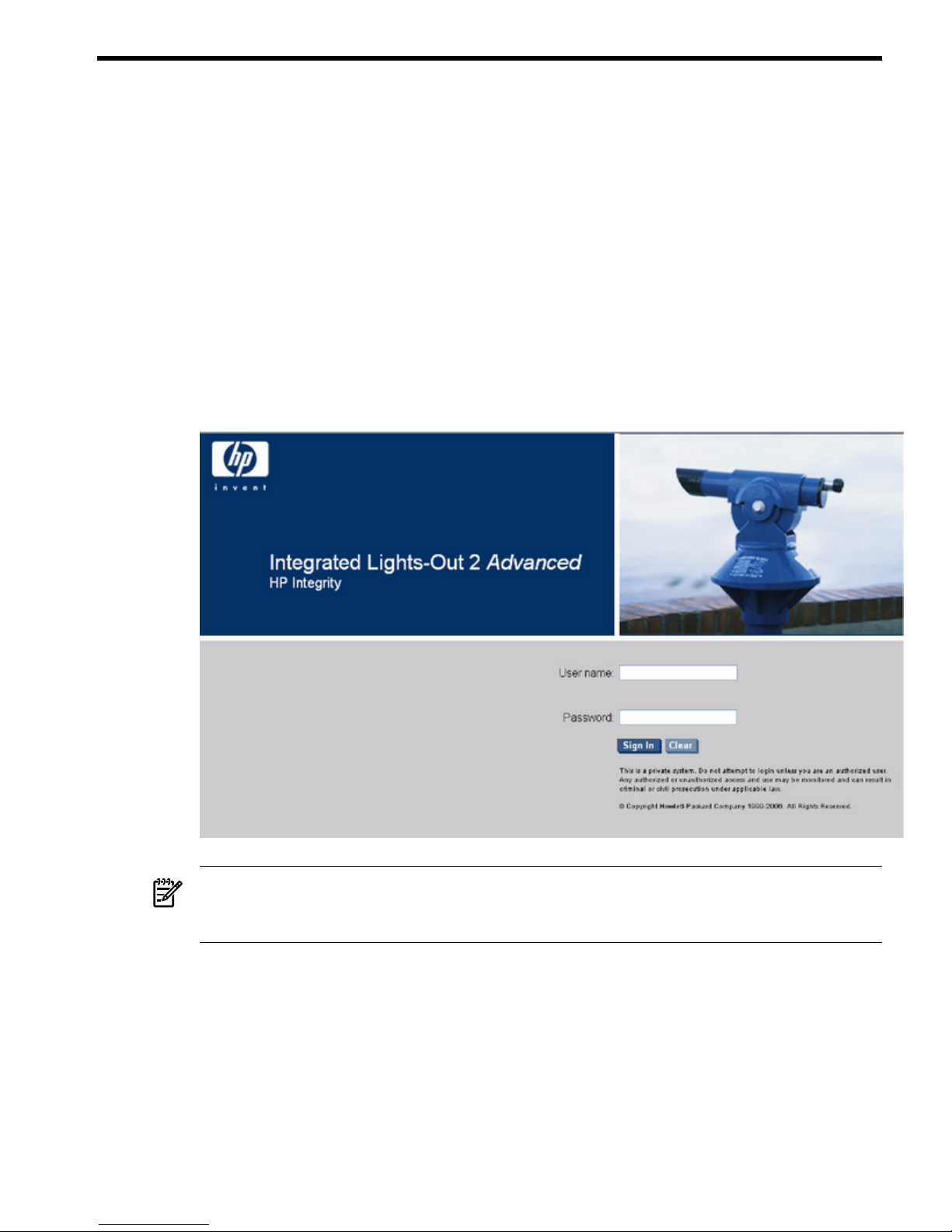
6 Accessing the Host (Operating System) Console
This chapter describes several ways to access the host console of an HP Integrity server.
Accessing a Text Host Console through iLO 2 Virtual Serial Console
Web browser access is an embedded feature of iLO 2.
Before starting this procedure, you must have the following information:
• DNS name for the iLO 2 MP LAN. This is found on the iLO Network Information Tag on
the server.
• Host name
To interact with iLO 2 through the web, follow these steps:
1. Open a web browser and enter the DNS name or the IP address for the iLO 2 MP.
2. Log in using your user account name and password at the login page. (Figure 6-1).
Figure 6-1 Web Login Page
NOTE: The iLO 2 web interface session times out after five minutes if there is no activity.
If you open a remote console terminal window, the system remains open in the web interface
session until you sign out. Also, the web session does not timeout if vMedia is connected.
3. Click Sign In. The Status Summary page (Figure 6-2) appears after login.
Accessing a Text Host Console through iLO 2 Virtual Serial Console 69
Page 70
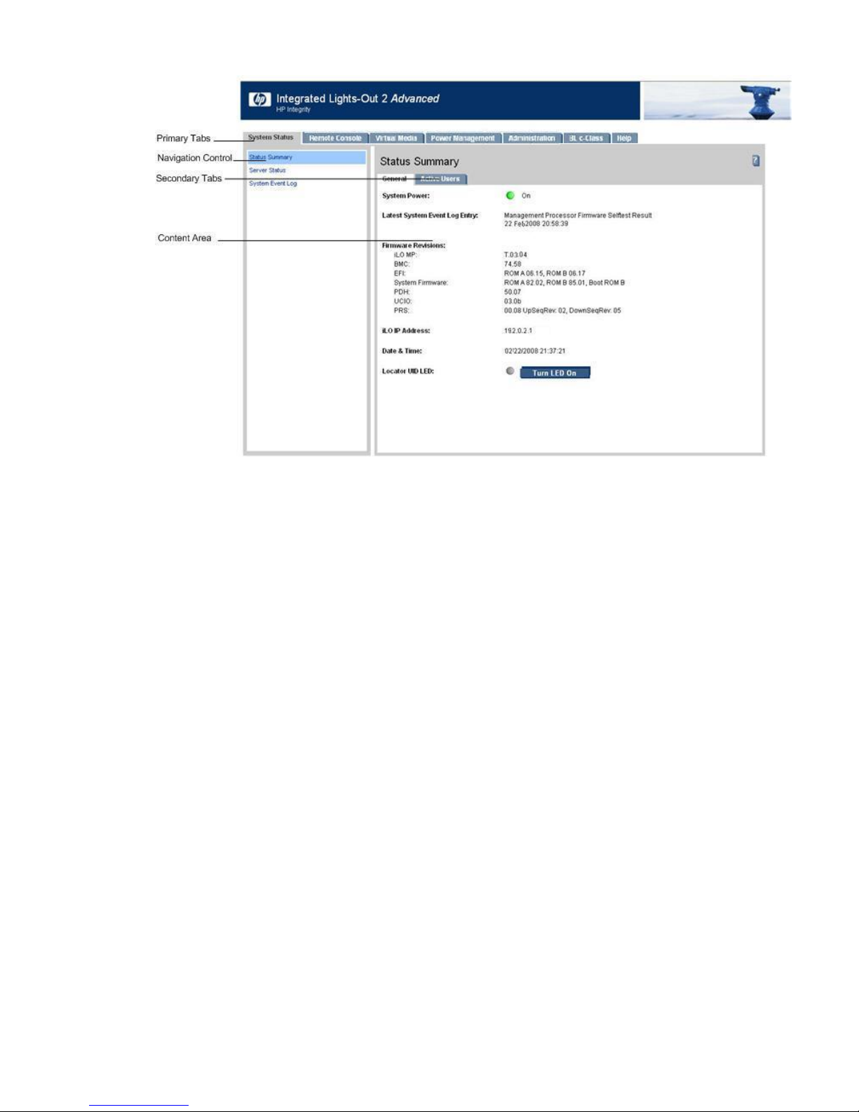
Figure 6-2 Status Summary Page
4. Select the web interface functions by clicking the Primary tabs at the top of the page. Each
function lists options in the Navigation Control on the left side of the page.
5. To display data in the content area; select an option and click Refresh to update the display.
6. Click the Remote Console tab. The remote console provides the following options to access
the console:
• A serial console that behaves similarly to the TUI
• The virtual KVM console
Accessing Online Help
The iLO 2 web interface has a robust help system. To launch iLO 2 help, click Help. Alternately,
click the ? at the top right corner of each page to display help about that page.
Accessing a Text Host Console Using the TUI
To access the host console using the text user interface (TUI), follow these steps:
1. Log in using your user account name and password at the login page.
2. To switch the console terminal from the MP Main Menu to mirrored/redirected console
mode, enter the CO command at the MP> login prompt. All mirrored data appears.
3. To return to the iLO 2 MP command interface, enter Ctrl-B or Esc (.
Help System
Integrity iLO 2 has a robust help system.
To access the Help menu from the TUI, enter HE at the MP> prompt. The following is the MP
Help Main Menu:
==== MP Help: Main Menu ===============================================
Integrated Lights-Out for HP Integrity and HP 9000 - Management Processor (MP) MP Help System
Enter a command at the help prompt:
OVerview : Launch the help overview
LIst : Show the list of MP Main Menu commands
70 Accessing the Host (Operating System) Console
Page 71

<COMMAND> : Enter the command name for help on individual command
TOPics : Show all MP Help topics and commands
HElp : Display this screen
Q : Quit help
====
MP:HE
To display the Main Menu Command List, enter LI at the MP HE: prompt.
To return to the MP Main Menu, enter Q.
To access help from the web GUI, click Help. You can also click the ? at the top right corner of
each page to display help about that page.
Accessing a Graphic Host Console Using the Integrated Remote Console
For information on how to access the host console using the vKVM feature through the Integrated
Remote Console (IRC), see “Accessing the IRC” (page 122).
Accessing a Text Host Console Using SMASH SM CLP
For information on how to access the host console using the SMASH SM CLP, see “Accessing
the SM CLP Interface” (page 152).
Accessing a Graphic Host Console Using the Integrated Remote Console 71
Page 72

72
Page 73

7 Configuring DHCP, DNS, LDAP, and Schema-Free LDAP
This chapter provides information on how to configure DHCP, DNS, LDAP extended schema,
and schema-free LDAP.
Configuring DHCP
DHCP enables you to automatically assign reusable IP addresses to DHCP clients. This section
provides information on how to configure DHCP options such as the Domain Name System
(DNS).
The iLO 2 MP host name you set through this method displays at the iLO 2 MP command mode
prompt. Its primary purpose is to identify the iLO 2 MP LAN interface in a DNS database.
NOTE: The HP-UX system name displayed by the uname -a command is different than the
iLO 2 MP host name.
If the IP address, gateway IP address, and subnet mask are obtained through DHCP, you cannot
change them without first disabling DHCP. If you change the host name and the IP address was
obtained through DHCP and registered with dynamic DNS (DDNS), a “delete old name” request
for the old host name and an “add name request” for the new host name are sent to the DDNS
server.
If you change the DHCP status between enabled and disabled, the IP address, subnet mask, and
gateway IP address are set to default values (127.0.0.1:0xffffff00). Also, the DNS parameters are
voided. When you change the DHCP status from enabled to disabled, the DNS parameters for
using DHCP are set to disabled, and the Register with DDNS parameter is set to No. When
you change the DHCP status from disabled to enabled, the DNS parameters for using DHCP are
set to enabled, and the Register with DDNS parameter is set to Yes.
NOTE: DNS is the comprehensive RFC standard; DDNS provides only a part of the DNS
standard functionality.
Use the LC command to perform the following actions to configure DHCP:
• Set all default LAN settings.
MP:CM> LC -all DEFAULT –nc
• Display current LAN settings.
MP:CM> LC -nc
• Modify the MP DHCP status.
MP:CM> LC -dhcp disabled
• Modify the MP IP address.
MP:CM> LC -ip 192.0.2.1
• Modify the MP host name.
MP:CM> LC -h hostname
• Modify the MP subnet mask.
MP:CM> LC -s 255.255.255.0
• Modify the MP gateway address.
MP:CM> LC -g 192.0.2.1
• Set the link state to autonegotiate.
MP:CM> LC -link auto
Configuring DHCP 73
Page 74

• Set the link state to 10 BaseT.
MP:CM> LC -link t
• Set the remote console serial port address.
MP:CM> LC -web 2023
• Set the SSH console port address.
MP:CM> LC -ssh 22
Configuring DNS
To use the DNS command to display and modify the DNS configuration, follow these steps:
1. From the MP Main Menu, enter command mode.
2. At the MP:CM> prompt, enter DNS. The screen displays the current DNS data.
3. When prompted, enter A to select all parameters. The screen displays the current DHCP for
DNS servers status.
4. When prompted, enter Enabled or Disabled. The screen displays the current DHCP for
DNS domain name status.
5. When prompted, enter Enabled or Disabled. The screen displays the current register
with DDNS server value.
6. When prompted, enter Yes or No. The screen displays the current DNS domain name.
7. When prompted, enter a new value. The screen displays the primary DNS server IP address.
8. When prompted, enter a new value. The screen displays the optional secondary DNS server
IP address.
9. When prompted, enter a new value. The screen displays the optional tertiary DNS server
IP address.
10. When prompted, enter a new value.
The DNS configuration is updated as follows:
New DNS Configuration (* modified values):
* S - DHCP for DNS Servers : Disabled
* D - DHCP for DNS Domain Name : Disabled
R - Register with DDNS Server : Yes
* N - DNS Domain Name : mpdns.company.com
* 1 - Primary DNS Server IP : 192.0.2.1
2 - Secondary DNS Server IP :
3 - Tertiary DNS Server IP :
Enter parameter(s) to revise, Y to confirm, or [Q] to Quit: Y
-> DNS Configuration has been updated
[mpserver] MP:CM>
Configuring LDAP Extended Schema
The following procedure shows how to configure iLO 2 to use a directory server to authenticate
a user login using the iLO 2 MP TUI.
NOTE: The LDAP connection times out after 30 minutes of inactivity in Active Directory. For
Novell directory, there is no inactivity timeout.
To configure using the web interface, see “Group Accounts” (page 140).
74 Configuring DHCP, DNS, LDAP, and Schema-Free LDAP
Page 75

NOTE: The LDAP feature is only available if you have the iLO 2 Advanced Pack license.
To configure LDAP extended schema, follow these steps:
1. From the MP Main Menu, enter command mode.
2. At the MP:CM> prompt, enter LDAP.
3. To select Directory Settings, enter D. The current LDAP directory settings appear.
4. To select all parameters enter A. The current LDAP directory authentication status appears.
The local iLO 2 user accounts database status also appears. If enabled, the local iLO 2 user
database is used if there is an authentication failure using the LDAP Directory.
5. Enter D for disabled, or E for enabled. You must enter E if LDAP directory authentication
is disabled. The current LDAP server IP address appears.
6. Enter the IP address of the LDAP server. The current LDAP server port address appears.
7. Enter a new port number. The screen displays the current object distinguished name. This
specifies the full distinguished name of the iLO 2 device object in the directory service. For
example, CN=RILOE2OBJECT, CN=Users, DC=HP, DC=com. Distinguished names are
limited to 255 characters maximum plus one for the NULL terminator character.
8. Enter a new name. The Current User Search Context 1 appears.
9. Enter a new search setting. The Current User Search Context 2 appears.
NOTE: The context settings 1, 2, and 3 point to areas in the directory service where users
are located, so that users do not have to enter the complete tree structure when logging in.
For example, CN=Users, DC=HP, DC=com. Directory user contexts are limited to 127
characters maximum plus one for the NULL terminator character for each directory user
context.
10. Enter a new search setting. The screen displays the Current User Search Context 3.
11. When prompted, enter a new search setting.
The updated LDAP configuration is as follows:
New Directory Configuration (* modified values):
* L - LDAP Directory Authentication : Enabled
M - Local MP User database : Enabled
* I - Directory Server IP Address : 192.0.2.1
P - Directory Server LDAP Port : 636
D - Distinguished Name (DN) : cn=mp,o=demo
1 - User Search Context 1 : o=mp
2 - User Search Context 2 : o=demo
3 - User Search Context 3 : o=test
Enter Parameter(s) to revise, Y to confirm, or [Q] to Quit: y
-> LDAP Configuration has been updated
Login Process Using Directory Services with Extended LDAP
You can choose to enable directory services to authenticate users and authorize user privileges
for groups of iLO 2s. The iLO 2 directory services feature uses the industry-standard LDAP. HP
layers LDAP on top of SSL to transmit the directory services information securely to the directory
servers. More information about using iLO with directory services is available from the HP
website at:
http://h20000.www2.hp.com/bc/docs/support/SupportManual/c00190541/
c00190541.pdf?jumpid=reg_R1002_USEN
HP provides a tool for Active Directory support of HP management processors. This tool,
HPQLOMIG.exe, is part of HP Directories Support for Management Processors softpaq (SP31581.exe).
Configuring LDAP Extended Schema 75
Page 76
It assists with installing the schema and snap-ins needed for Active Directory to work with iLO
2 products including Integrity iLO 2. This is for set up and management. It will not do automatic
migration for you. For Integrity iLO 2, you must manually add iLO 2 objects to the directory
server and set up user accounts and privileges. You can find the tool on the HP website at:
http://h20000.www2.hp.com/bizsupport/TechSupport/
SoftwareDescription.jsp?lang=en&cc=US&swItem=MTX-UNITY-I23896
Using directory services after users enter their login and password, the browser sends the cookie
to iLO 2. The iLO 2 processor accesses the directory service to determine which roles are available
for that user login. iLO 2 first uses the credentials to access the iLO 2 device object in the directory.
The directory service returns only the roles for which the user has rights. If the user credentials
allow read access to the iLO 2 device object and the role object, iLO 2 determines the role object’s
distinguished name and the associated user privileges. iLO 2 then calculates the current user
privileges based on those roles and grants them to that user.
Configuring Schema-Free LDAP
IMPORTANT: Due to command syntax changes in schema-free LDAP, some customer-developed
scripts may not run. You must change any scripts you developed to enable them to run with the
new schema-free LDAP syntax.
Integrity iLO 2 schema-free directory integration enables you to use the standard directory
schema instead of adding HP’s schema to the directory database. You accomplish this by
authenticating users from the directory database and authorizing iLO 2 privileges based on
matching groups stored on each iLO 2.
NOTE: Schema-Free LDAP is available only if you have the iLO 2 Advanced Pack license.
In addition to general directory integration benefits, iLO 2 schema-free integration provides the
following advantages:
• Easy implementation without schema extensions.
iLO 2 schema-free integration is configured from any iLO2 user interface (browser, command
line, or script).
• Minimal administration and maintenance.
— After initial setup, only groups and permissions require maintenance support on iLO
2; typically group and permission changes occur infrequently.
— The schema-free approachdoes not require updating directory databases withnew iLO
2 devices objects.
• Reliable security.
Integrity iLO 2 schema-free integration does not affect standard directory attributes, avoiding
conflicting use of attributes that can result over time.
• Complements two-factor authentication.
Integrity iLO 2 schema-free integration can be used in conjunction with iLO 2 two-factor
authentication to provide asset protection using strong authentication.
NOTE: If you have already extended your directory with HP schema, there is no need to switch
to the schema-free approach. Schema extension provides the lowest maintenance approach for
directory integration. Once this process has taken place, there is no advantage for the schema-free
approach until a schema change is required.
To configure schema-free LDAP, follow these steps:
76 Configuring DHCP, DNS, LDAP, and Schema-Free LDAP
Page 77

1. Follow the procedure for “Configuring LDAP Extended Schema” (page 74), but omit Step
8. It is not necessary to enter a new port number.
2. Set up directory security groups.
Setting Up Directory Security Groups
The following procedure describes how to set up directory security groups in schema-free LDAP
using the iLO 2 MP TUI. To use the web interface, see “Group Accounts” (page 140).
NOTE: Due to command syntax changes in schema-free LDAP, some customer-developed
scripts may not run. You must change any scripts you developed to enable them to run with the
new schema-free LDAP syntax.
NOTE: You must select the default schema from the LDAP command for the schema-free LDAP
settings to work.
To set up directory security groups, follow these steps.
1. At the MP:CM> prompt, enter LDAP. The screen displays the current LDAP options.
[hqgstlb3] MP:CM> ldap
LDAP
Current LDAP options:
D - Directory settings
G - Security Group Administration
2. Enter G. The current group configuration appears.
Enter menu item or [Q] to Quit:G
Current Group Configuration:
Group Names Group Distinguished Names Access Rights
--------------------------------------------------------------------------
1 - Administrator C, P, M, U
2 - User C, P
3 - Custom1 None
4 - Custom2 None
5 - Custom3 None
6 - Custom4 None
Only the first 30 characters of the Group Distinguished Names are displayed.
Enter number to view or modify, or [Q] to Quit:
3. Enter the number for the group you want to view or modify. The current LDAP group
settings appear.
4. Set up a group distinguished name.
5. Select rights for the group.
6. Enter Y to confirm.
Login Process Using Directory Services Without Schema Extensions
You can control access to iLO 2 using directories without schema extensions. iLO 2 acquires the
user name to determine group membership from the directory. iLO 2 then cross-references the
group names with its locally stored names to determine user privilege level. iLO 2 must be
configured with the appropriate group names and their associated privileges. To configure iLO
2, use one of the following methods:
• Web GUI (Administration > Directory Settings > Group Administration page)
• iLO 2 MP TUI (LDAP command)
Configuring Schema-Free LDAP 77
Page 78

LDAP and MP Login for Integrity Cell-Based Servers
This sectionprovides information on LDAP and MP login access rights and partitionconfiguration
in iLO 2 for Integrity cell-based servers. System administrators can use this information to create
and assign access rights.
This section explains the following:
• User login functions when configured with different rights for different partitions
• User management and privileges required to execute commands in iLO 2
Integrity iLO 2 is an independent support processor that provides systemmanageability features
for a multi-partition server.
The following rules apply:
• Multiple users can simultaneously log in through the LAN port and independently manage
partitions or view the server status.
• Local or LDAP users can have rights.
• A user who has rights on multiple partitions can have the same or different rights for each
partition.
• For all operations that are not partition-specific, a user must have a specific right for all
partitions to which access is granted.
The iLO 2 supports multiple sessions that perform independent tasks and enables the following
usage models:
• A user can have multiple windows logged into iLO 2, and can perform long-term tasks such
as monitoring virtual front panels or studying event logs in some windows while
simultaneously performing short-term tasks like administering partitions from other
windows.
• A user can independently connect to different partitions and manage them simultaneously.
• A user can reset a partition from one window and monitor the boot from another window
while interacting with the console from yet another.
User Accounts
LDAP enables you to define iLO 2 user accounts in a centralized database on an LDAP server.
LDAP directory support is an iLO 2 advanced feature that enables centralized, user account
administration using directory services.
Commands
The iLO 2 commands have access levels to manage users effectively. Because iLO 2 commands
work at different combinations of these access levels, you must understand how to categorize
the commands.
The iLO 2 user interface has commands that can be classified into the following categories. Each
category requires certain access rights as shown in Table 7-3.
Partition-specific Commands These commands are partition-specific. They include commands
that operate on a specified partition.
78 Configuring DHCP, DNS, LDAP, and Schema-Free LDAP
Page 79

Composite Commands These commands have sub commands within themthat require different
rights to execute. For example the SOcommand has User Parameters, MP-wide parameters
within it. Each sub command needs rights as follows:
• MP:CM> so
— MP wide parameters [U]
— User parameters [M]
— IPMI password [M]
— OS initiated firmware update permissions [M]
— Regenerate the SSH server public key [M]
Special Commands These commands include operations that affect the cell, cabinet, or complex,
and only users having ‘All’ rights for ‘All’ supported partitions are allowed to execute these
commands.
MP-wide Commands MP-wide commands require a specific command right for all partitions
that a user has access to.
The iLO 2 commands are grouped in the above-mentioned categories, as shown in Table 7-1.
Table 7-1 Command Categories
Special CommandsComposite Commands
Partition-Specific
CommandsMP-Wide Commands
pexdbocccp
resorrdatede
ru (KMIX only)clrsdcdf
vm (sx2000 only)sltcdidu
cofwhe
clidif
ltls
lcma
ldapps
parpermte
rlwho
sax
sysrevhe
dnspwrgrd
locpd
snmpvfp
ups
fw
io
Access Rights
An iLO 2 user can have any, or all, of the following access rights:
LDAP and MP Login for Integrity Cell-Based Servers 79
Page 80

Table 7-2 Access Rights for Cell-Based Servers
Description
Single Letter
RepresentationAccess Right
This right is required to perform any operation on iLO 2.
A user must have this right for each partition to which access is
granted.
With this right, a user can run Status or Read-only commands.
LLogin Access
This right enables a user to access the console of the specified
partition (such as the host OS).
Console Access Level CO Command.
CConsole Access
This right enables a user to power on and off or reset the host
platform.
PServer Power Access
This right enables a user to configure iLO 2 parameters.
Some examples of commands that are used to configure MP
parameters are CA, CC, CG, DATE, DC, DI, ID, IT,
LC, LDAP, MFG, PARPERM, and RL.
MMP Configuration Access
This right enables a user to create, modify, and delete local iLO
2 user accounts and set the default partition for a session.
Examples of an MP Local User Administration Level Command
are SO and PD.
UUser Administration
Access
This right enables a user to control and access vMedia for the
selected partition.
VVirtual Media Access
Table 7-3 lists the iLO 2 commands and the access right associated with each command.
Table 7-3 Commands and Associated Access Right
Access RightLocationCommand
Server Power AccessCommand MenuBO
Server Power AccessRR
Server Power AccessRS
Server Power AccessTC
MP Configuration AccessCC
Login AccessCP
MP Configuration AccessDATE
MP Configuration AccessDC
Login AccessDE
Login AccessDF
MP Configuration AccessDI
Login AccessDU
Login AccessHE
MP Configuration AccessID
Login AccessIF
MP Configuration AccessIT
MP Configuration AccessLC
80 Configuring DHCP, DNS, LDAP, and Schema-Free LDAP
Page 81

Table 7-3 Commands and Associated Access Right (continued)
Access RightLocationCommand
MP Configuration AccessLDAP
Login AccessLS
Login AccessMA
MP Configuration AccessPARPERM
User Administration AccessPD
All for all supported partitionsPE
Login AccessPS
Server Power AccessPWRGRD
All for all supported partitionsRE
All for all supported partitionsRU (KMIX only)
MP Configuration AccessSA
1. MP Wide Parameters - MP Configuration rights for all partitions to
which the user has access
2. User Parameters - User Admin rights for all partitions to which the
user has access
3. IPMI Password - MP Configuration rights for all partitions to which
the user has access
4. OS initiated FW - MP Configuration rights for all partitions to which
the user has access
5. Regenerate SSH Certificate - MP Configuration rights for all partitions
to which the user has access
SO
MP Configuration AccessSYSREV
Login AccessTE
Login AccessWHO
1. Parameters Checksum and Ping - Login rights for all partitions that
user has access to
2. Soft Resetfor Master/Slave& IOX Master/Slave MP - MP Configuration
rights for all partitions to which the user has access
3. Clear Persistent Parameters- User Admin rights andMP Configuration
rights (for all partitions to which the user has access)
4. Reset Security Parameters - User Admin rights for all partitions to
which the user has access
5. Force/Recover Master - Slave FailOver - MP Configuration rights for
all partitions to which the user has access
6. Toggle Master/Slave FailOver Enable - MP Configuration rights for all
partitions to which the user has access
XD
MP Configuration AccessDNS
MP Configuration AccessLOC
MP Configuration AccessSNMP
MP Configuration AccessUPS
MP Configuration AccessFW
1. View logs - Console rights for a partition
2. Clear logs- MP Configuration rights for all partitions to whichthe user
has access
CI
LDAP and MP Login for Integrity Cell-Based Servers 81
Page 82

Table 7-3 Commands and Associated Access Right (continued)
Access RightLocationCommand
Console AccessCO
Login AccessHE
1. View SEL, FPL, LIVE - Login rights for all partitions to which the user
has access
2. View iLO 2 event log - Login rights for all partitions to which the user
has access
3. View MPEL Logs - MP Configuration rights for all partitions to which
the user has access
4. Clear SEL & FPL Logs - MP Configuration rights for all partitions to
which the user has access
SL
Login AccessVFP
Login AccessX
MP Configuration AccessMPEL
Login AccessCommand MenuIO (sx2000 only)
All for all supported partitionsCommand MenuVM (sx2000 only)
These access rights work in conjunction with the three different kinds of partition user support
options.
Partition User Support Options
In a server that supports multiple partitions, the following options are available for partition
users. A user can be configured for any of the following partition usage levels:
Single Partition Use A user could have access to any one partition with rights defined.
Multipartition User, Same Rights A user can have access to multiple partitions of a server but
with the same rights for all the partitions.
Multipartition User, Different Rights A user can have access to multiple partitions with different
rights for all the partitions.
If a server has multiple partitions, the following rules apply for a user:
• Each user, at the time of creation, is classified either as an all or #partition user. A
partition might or might not be configured in the system.
• Login rights are required for a user to login. These rights are checked before running each
command to ensure that LOGIN rights are not revoked in the interim. A user with L rights
can run all commands related to status and read-only commands.
• When a user tries to run partition-specific commands but the partition is not configured, a
message appears that the partition is not configured
• Special commands such as pe, ru, and re require a user to have all rights to all partitions.
These commands can affect cells that are considered ‘free cells’ (not associated with any
partitions). Therefore, this mandate applies to users before running special commands.
• For all MP-wide commands (such as ldap, lc, and so on), a user must have corresponding
rights for all partitions that the user has access to.
• When assigning rights to user logins in a multiserver environment, remember the various
combinations of available rights, types of commands, and partition authority.
82 Configuring DHCP, DNS, LDAP, and Schema-Free LDAP
Page 83

8 Using iLO 2
This chapter provides information on the different interfaces you can use to interact with iLO 2
such as text user interface, web GUI, and SMASH SM CLP.
Text User Interface
This section provides information on the text user interface commands you can run in iLO 2.
NOTE: HP Integrity server blades do not have fans or power supplies. Therefore, their response
to certain commands are different than a rackmount server.
MP Command Interfaces
Table 8-1 lists and describes the available MP command interfaces.
Table 8-1 MP Command Interfaces
DescriptionMP Command Interface
The MP Main Menu appears when you first access the iLO 2 MP. The MP Main Menu
supports the basic MP commands for server control and the iLO 2 MP configuration,
such as setting up the iLO 2 MP LAN, retrievingevents, resetting and powering on control
of the server, switching to the console, and so on. You can enter the MP Main Menu
commands at the MP> prompt.
MP Main Menu
The Command menu provides a set of commands that help monitor and manage the
server. It switches the console terminal from the MP Main Menu to command interface
mode. You can access commands that are not displayed inthe MPMain Menuby entering
CM at the MP Main Menu and entering HE LI at the MP:CM> prompt to get a list of the
available commands.
Command Menu
The Systems Management Architecture for Server Hardware (SMASH), Server
Management Command Line Protocol (SM CLP) initiative is an effort within the
Distributed Management Task Force (DMTF) to standardize commands for servers. The
SMASH SMCLP specifies common command line syntax and message protocolsemantics
for server management.
NOTE: SMASH SM CLP commands are only available for entry class servers.
For information on using SMASH SM CLP scripting commands, see Section : “SMASH
Server Management Command Line Protocol” (page 152).
SMASH SM CLP
Figure 8-1 displays the MP command interface options.
Text User Interface 83
Page 84
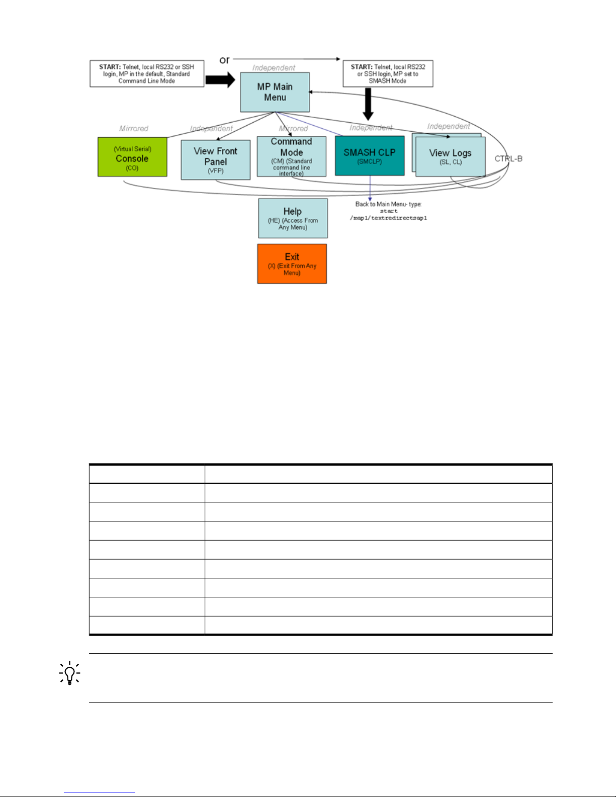
Figure 8-1 MP Command Interfaces
MP Main Menu
After logging in to the iLO 2 MP, the MP Main Menu appears. The MP Main Menu runs as a
private session. Other iLO 2 users do not see the actions you perform in the private session.
Integrity iLO 2 can support multiple sessions to perform independent tasks:
• Multiple windows logged into iLO 2 to monitor VFP or study event logs in one window
while administering the server from another window.
• Resetting a server from one window and monitoring the boot from another window while
interacting with the console from a third window.
Table 8-2 lists the MP Main Menu commands.
Table 8-2 MP Main Menu Commands
DescriptionCommand
Selects console mode
CO
Displays the virtual front panel
VFP
Enters command interface mode
CM
Accesses the SMASH SM CLP
SMCLP
Views the console log
CL
Shows event logs
SL
Displays help for the menu or command
HE
Exits
X
TIP: An effective method for using iLO 2 is to log in more than once with different views for
each session. For instance, one window logged in viewing the console, and another viewing the
virtual front panel.
MP Main Menu Commands
MP Main Menu command descriptions are listed as follows:
84 Using iLO 2
Page 85

CO (Console): Leave the MP Main Menu and enter console mode
CO switches the console terminal from the MP Main Menu to mirrored/redirected console mode.
All console output is mirrored to all users in console mode. Only one of the mirrored users at a
time has write access to the console. To get console write access, press Ctrl-Ecf.
Press either Ctrl-B or Esc and ( to return to the iLO 2 MP command interface. Verify that all
mirrored consoles are of the same terminal type for proper operation.
To run an ASCII screen-oriented application (SAM) or a file transfer program (ftp), the console
is not the recommended connection. HP recommends using the LAN and connecting directly
with Telnet or the web to the system over the system LAN.
VFP (Virtual Front Panel): Simulate the display panel
VFP simulates the display panel on the front of the server. It gives realtime feedback on the results
of system events and user actions. VFP works by decoding system events. It provides a live
display of major states of the system, the latest system activity, and the state of front panel LEDs.
VFP shows forward progress during boot by indicating how many events have been received
since the boot started and whether there have been any errors (events with alert level 3 or greater)
since the last boot. To clear the yellow attention indicator on the front of the system, use the SL
command and access the System Event Log (SEL).
Each user viewing VFP is in private session mode.
See also: LOC (locator LED) and, SL (show logs).
CM (Command Mode): Enter command mode
CM switches theconsole terminal from the MP Main Menu to mirrored command interfacemode.
The Command menu provides you with a set of standard command line interface commands
that help monitor and manage the server.
To display the list of MP command mode commands that are not displayed in the MP Main
Menu, follow these steps:
1. From the MP Main Menu, enter HE.
2. Enter LI after the MP HELP:> prompt.
If a command is in progress, a system status message appears.
To return to the MP Main Menu, press CTRL-B.
SMCLP (Server Management Command Line Protocol): Switch to the SMASH SMCLP
SMCLP switches the console terminal from the MP Main Menu to the SMASH SMCLP interface.
For information on SMASH SM CLP see “SMASH Server Management Command LineProtocol”
(page 152).
CL (Console Log): View the history of the console output
CL displays up to 60 KB of logged console data (about 60 pages of display in text mode) sent
from the system to the console path and stored for later analysis.
Console data is stored in a buffer in nonvolatile memory. By default, data is displayed from the
beginning of the buffer to end of the buffer. You can control the starting point from which the
data displays and navigate through the data.
An image of the console history appears when you enter the CL command. Console output
continues to be logged while this buffer is read, and nothing is lost.
SL (Show Logs): View events in the log history
SL displays the contents of the event logs that are stored in nonvolatile memory.
Text User Interface 85
Page 86

Events communicate system information from the source of the event to other parts of the system,
then to you. Events are produced by intelligent hardware modules, the operating system, and
system firmware. Events funnel into the BMC from different sources throughout the server. iLO
2 polls the BMC for new events and stores them in nonvolatile memory.
SL also displays the contents of the iLO 2 Event Log. The records the following events:
• iLO 2 MP login and logout attempts
• Command logging for specific commands
• All entries in the existing history log with more detail
Each time a user logs in or out of iLO 2, an event is logged. In the event of a login failure, an
event is logged if the number of continuous login failure attempts equals the password fault
value.
Command logging is run for the following commands: BP, CA, DC, DI, DNS, FW, ID,
IT, LC, LDAP, LM, PC, PM, PR, RB, RS, SA, SNMP, SO, TC, UC
Events are listed as follows:
SEL: System Error Log High-attention events and errors
FPL: Forward Progress Log All events
Boot Log All events between start of boot and boot complete
Previous Boot Log The events from the previous boot
Reading the SEL is the only way to turn off the attention LED (flashing yellow light).
Table 8-3 lists the events and actions used to navigate within the logs.
Table 8-3 Events
ActionEvent
Displays the next block (forward in time)+
Displays the previous block (backward in time)-
Continues to the next or previous blockEnter (<CR>)
Dumps the entire log for capture or analysisD
Displays the first entryF
Displays the last entryL
Jumps to entry numberJ
Displays the mode configuration (hex)H
Displays the mode configuration (keyword)K
Displays the view mode configuration (text)T
Displays the alert level filter optionsA
Displays the alert level unfilteredU
Quits and returns to the Event Log Viewer MenuQ
Displays the Help Menu?
Exits and returns to the MP Main MenuCtrl-B
Integrity iLO 2 Event Log navigation provides additional filtering options as shown in Table 8-4.
86 Using iLO 2
Page 87
Table 8-4 iLO 2 Event Log Filter Options
Filter CriteriaFiltering Option
Filter by user Login IDN: User Login
Filter by port name (Serial, Telnet, SSH, WEB)P: Port Name
Filter by user IP Address (dotted decimal format)I: IP Address
Filter by date stamp of the records entries (MM/DD/YYYY)M: Date
If you select more than one filtering option, it acts as an additional filter. For example, if you
select the filtering option N followed by P, the logs displayed are the logs that satisfy the filtering
criteria for options N and P.
NOTE: The iLO2 Event Logs cannot be cleared.
A finite number of records are stored. The older records are replaced as the log fills up.
Table 8-5 lists alert (severity) levels.
Table 8-5 Alert Levels
DefinitionSeverity
Minor forward progress0
Major forward progress1
Informational2
Warning3
Critical5
Fatal7
See also: DC (default configuration) and VFP (virtual front panel).
SL Command for Integrity Cell-Based Servers
SL: Show Logs - View the events in the log history.
SL displays the contents of the events that have been stored in nonvolatile memory.
Events are data items that communicate system information from the source of the event to other
parts of the system, and ultimately to the system administrator. Events are produced by intelligent
hardware modules, the operating system, and system firmware. Events funnel into iLO 2 from
different sources throughout the server.
Events can be a result of a failure or an error (such as fan failure, machine-check, and so on).
They can indicate a major change in system state (firmware boot start, system power on/off) or
they might be forward progress markers, (such as CPU self test complete). Event data indicates
what the event was, where it happened, and the severity of the event. The most important events
are error logs (alert level 3 or higher), and major change of state logs, because they give information
that can provide clues about the cause of anomalous behavior. The log viewer contains an event
decoder to help you interpret events.
Table 8-6 lists events, actions, and functions of the logs.
Text User Interface 87
Page 88

Table 8-6 Events and Actions
FunctionsActionEvent
New events overwrite old FPL events once the FPL is full.Forward Progress Log Stores all events of level
0 or greater
FPL
New events are not logged to the SEL when the SEL is full. Thus, it is
necessary for a user or an application to periodically clear the SEL. Reading
the SEL turns off the attention LED. Accessing this buffer is the only way to
turn off the attention LED when it is flashing.
System Error Log Stores all events of level
2 or greater
SEL
New events overwrite old MPEL events once the MPEL is full.
The iLO 2 MPEL records the following events:
• iLO 2 MP login, logout attempts and login failure records
• MP firmware upgrade
• MP firmware activate event
• Console access
• Clearing of logs
MPEL logs cannot be cleared.
Formatting options are not available for MPEL.
MP Event Log - Stores
user action events
including user login
MPEL
The Live Logs feature enables you to apply a filter, and filter out logs by
cell or by partition, or to view only error logs.
Displays events, live as
they occur
Live Logs
The Clear Logs command clears both the FPL and SEL. It is useful for
getting a "clean log trace". A user with Console access right can view the
System Event Log. Only a user with iLO Configuration access right can clear
the logs.Login rights are sufficient to view the logs. But for clearing the logs,
iLO Configurationrights are required for allthe partitions to which user has
access. But MPEL logs cannot be cleared.
Clears the activity and
error log buffers
Clear Logs
Keyword Format For the event logs, the default format is Keyword (keyword plus hex). SEL
and FPL provide formatting options, the other two formats are raw hex mode and text mode.
Text mode gives a multi-line display that is more readable and decodes any physical location
data.
The (D)ump command dumps the entire log in keyword format. It is useful for capturing the log
contents to a file and emailing it for analysis by support personnel.
Navigation Navigation commands enable you to move forward or back a screen at a time, and
to jump to a specific log number or to the first or last log entry.
Table 8-7 lists the navigation commands and their actions.
Table 8-7 Navigation Commands
Action
Navigation
Command
Dump logstarting at current block for capture and analysis (forSEL andFPL) Dump log starting
from the beginning (for MPEL)
D
Display first (oldest) blockF
Display last (newest) blockL
Jump to specified entry and display previous blockJ
Display next (forward in time) block+
Display previous (backward in time) block-
Repeat previous +/- command<cr>
Repeat previous +/- command<sp>
88 Using iLO 2
Page 89

Table 8-7 Navigation Commands (continued)
Action
Navigation
Command
Display help?
Exit viewerCtrl-B
NOTE: The MPEL log history display provides the same navigation commands as the FPL and
the SEL except for the D command.
MPEL log navigation provides the following filtering options:
Table 8-8 MPEL Log Navigation Filter
ActionMPEL Log Navigation Filter
Filter by User Login IDS : User Login
Filter by User Login Method (Serial, Telnet, SSH, WEB)P : Login Method
Filter by user IP Address (dotted decimal format)I : IP Address
Filter by date stamp of the record entries (MM/DD/YYYY)T : Date
Switch back to unfiltered stateU : Unfiltered
HE (Help): Display help for the menu or command in the MP Main Menu
HE displays help for the menu or command.
• If executed from the MP Main Menu, HE displays general information about iLO 2, and
those commands available in the MP Main Menu.
• If executed in command mode, HE displays a list of Command menu commands available.
It also displays detailed help information in response to a topic or command at the help
prompt.
X (Exit): Exit iLO 2
X exits you from the MP Main Menu. If the terminal is the local serial port, the login prompt
appears. For all other types of terminals, you are disconnected from iLO 2.
Command Menu
The Command menu provides you with a set of standard command line interface commands
that help monitor and manage the server.
Table 8-9 lists the Command menu commands.
Table 8-9 Command Menu Commands
DescriptionCommand
Resets the BMC passwords
BP
Displays blade parameters
NOTE: This command is available only on a server blade.
BLADE
Configures asynchronous local serial port
CA
Displays the current date
DATE
Resets all parameters to default configuration
DC
Displays field replaceable unit (FRU) information
DF
Text User Interface 89
Page 90

Table 8-9 Command Menu Commands (continued)
DescriptionCommand
Disconnects the LAN console
DI
Sets the DNS configuration
DNS
This command is only available to authorized HP service personnel
FW
Displays help for the menu or command
HE
Displays or modifies system information
ID
Modifies the iLO 2 inactivity timeouts
IT
Displays the LAN configuration
LC
Displays the LDAP configuration
LDAP
License management
LM
Displays and configures locator LED
LOC
Displays the LAN status
LS
Remote power control
PC
Remote power mode control
PM
Configures the power restore policy
PR
Displays the power management module status
PS
Resets the BMC
RB
Resets the system through the RST signal
RS
Sets access options
SA
Configures SNMP parameters
SNMP
Configures security options
SO
Displays system processor status
SS
Displays all firmware revisions
SYSREV
Resets through transfer of control (TOC)
TC
“Tell” (sends a message to other users)
TE
Displays a user configuration
UC
Displays connected iLO 2 users
WHO
Diagnoses or resets iLO 2
XD
The following is a quick reference list that provides MP Command mode activities:
To access the Command menu, enter CM at the MP Main Menu.
To see all the available commands, enter HE LI at the MP:CM> prompt.
To access the Command menu help, enter HE at the MP:CM> prompt. The Command menu help
provides information on all the Command menu items.
To modify the inactivity timeout, enter the IT command. The inactivity timer aborts a command
if you do not complete it within a certain time period and redirects you back to the command
prompt.
To abort most commands, enter Q at the point when the iLO 2 MP is asking for input.
To return to the MP Main Menu from any of these commands, press Ctrl-B.
90 Using iLO 2
Page 91

Command Line Interface Scripting
A command line interface is provided for all commands to assist you in scripting. This section
provides syntax examples used in the iLO 2 MP command-line or scripted interface.
Typically, tools like Expect (see “Expect Script Example” (page 91)) and (http://expect.nist.gov/)
are used to string together several commands to accomplish a task. These scripting tools enable
you to write a script for one iLO 2, and use it to apply the same commands to additional iLO 2s.
Scripting tools have capabilities that enable you to do the following:
• Write scripts that make decisions based on the output of commands
• Use variables in the script to customize it for each target automatically
• Compensate for delays in output
Scripting tools and the command-line interfaces enable you to carry out commands to multiple
iLO 2s such as setting the IP address on 10 iLO 2s pulled from a list of 10 IP addresses read from
a file local to your script. To automatically administer any part of the system during any stage
of its operation, you can use the scripting tool to log in to iLO 2, access the console, and send
and receive commands in EFI or the OS.
NOTE: This guide is not meant as a substitute for instruction on various scripting tools that
are available for automating command-line interfaces. The iLO 2 MP TUI (when used with
command-line arguments) and the SMASH command-line interface were created with these
types of scripting tools in mind to facilitate powerful automation capabilities.
Expect Script Example
The following provides a simple Expect script example with no timeouts and no error checking
using Telnet instead of SSH.
#!/usr/local/bin/expect -f
#
# (Portions of) this Expect script (were) was generated by autoexpect on
# Tue Nov 21 08:45:11 2006
# Expect and autoexpect were both written by Don Libes, NIST.
#
# Note that autoexpect does not guarantee a working script. It
# necessarily has to guess about certain things. Two reasons a script
# might fail are:
#
# 1) timing - A surprising number of programs (rn, ksh, zsh, telnet,
# etc.) and devices discard or ignore keystrokes that arrive "too
# quickly" after prompts. If you find your new script hanging up at
# one spot, try adding a short sleep just before the previous send.
# Setting "force_conservative" to 1 (see below) makes Expect do this
# automatically - pausing briefly before sending each character. This
# pacifies every program I know of. The -c flag makes the script do
# this in the first place. The -C flag allows you to define a
# character to toggle this mode off and on.
set force_conservative 0 ;# set to 1 to force conservative mode even if
;# script wasn't run conservatively originally
if {$force_conservative} {
set send_slow {1 .1}
proc send {ignore arg} {
sleep .1
exp_send -s -- $arg
}
}
#2) differing output - Some programs produce different output each time
# they run. The "date" command is an obvious example. Another is
# ftp, if it produces throughput statistics at the end of a file
Text User Interface 91
Page 92

# transfer. If this causes a problem, delete these patterns or replace
# them with wildcards. An alternative is to use the -p flag (for
# "prompt") which makes Expect only look for the last line of output
# (i.e., the prompt). The -P flag allows you to define a character to
# toggle this mode off and on.
#
# Read the man page for more info.
#
# -Don
#
# (End of auto-expect generated content)
#######################################################################
# USER
set mp_user "Admin"
# PASSWORD- get password from terminal instead of storing it in the script
stty -echo
send_user "For user $mp_user\n"
send_user "Password: "
expect_user -re "(.*)\n"
set mp_password $expect_out(1,string)
stty echo
# Other Constants
set timeout 20
########################################################################
## BEGIN
##
spawn $env(SHELL)
match_max 100000
#foreach mp_name {puma_mp lion_mp cougar_mp} {
set mp_name "puma_mp"
send_user "\n\n----- $mp_name -----\n\n"
# Frequently used Strings
set MA_PROMPT "$mp_name\] MP> $"
set CM_PROMPT "$mp_name\] MP:CM> $"
# Expect the UNIX prompt...
#expect "-> $"
#### Log into the MP #####
send -- "telnet $mp_name\r"
expect ".*MP login: $"
send -- "$mp_user\r"
expect "MP password: $"
send -- "$mp_password\r"
expect "$MA_PROMPT"
#Run SL command to dump logs
#send "sl -forward -view text -nc\r"
send -- "cm\r"
expect "$CM_PROMPT"
#Run PC command to power on the system
send -- "pc -on -nc\r"
expect "$CM_PROMPT"
send "ma\r"
expect "$MA_PROMPT"
92 Using iLO 2
Page 93

send "x\r"
#}
expect eof
Command Menu Commands and Standard Command Line Scripting Syntax
The following list of commands is provided to help you learn about the Command menu
commands. Command-line interface scripting syntax for each command is provided to help you
accomplish a scripting task. The following rules apply to scripting syntax:
• The -nc (no confirmation) is optional. This special keyword designates that no user
confirmation isrequired to execute the command. If you enter -nc at the end of the command
line, the command is executed without asking you for user input. Without the -nc option,
you are asked to confirm the changes. The only exception to this rule is when a password
must be entered. In that case, you are prompted for a password separately. However,
commands that require a password can have that password entered on the command line
(FW, UC).
If -nc is specified on a command with no otherparameters or with only a specific multilevel
selector, the command displays all or just the specific multilevel parameters. The absence
of a specific multilevel parameter on a command that has multilevels causes all the multilevel
parameters to display.
• Most commands accept -all default. This causes all parameters for that command to
be set to their default values.
• In some multilevel commands, you can use default to set that level to its default values.
• Further use of default on many individual parameters causes that parameter to be set to
its default value.
• -? (MP command-specific help) is optional. If you enter -? by itself with the command, a
usage display appears. In the event of an incorrect command line usage, in addition to the
error message, the usage display appears.
• Arguments in brackets [ ] are optional.
• Without arguments, the system prompts you for answers to questions.
• Entering a command without parameters takes you through the command interactively and
prompts you for all the options.
BP: Reset BMC passwords
Command access level: MP configuration access
BP resets the passwords that control the interface between the SFW and the BMC.
NOTE: The passwords that control the interface between the SFW and the BMC have nothing
to do with the MP login/passwords.
Setting these passwords at EFI, enables you to restrict access to various information. To clear
these passwords, use the BP command.
Command line usage and scripting:
BP [ -nc ]
-?
See also: DC, RB, UC
Text User Interface 93
Page 94

BLADE: Display BLADE parameters
NOTE: This command is available only on a server blade.
Command access level: Login access
BLADE facilitates the cabling and initial installation of HP Integrity server blades. It also provides
a quick view of the enclosure status. You must have configuration access right to turn the enclosure
locator UID LED on or off.
Onboard Administrator Configuration
OA IP Address IP address of the OA.
OA MAC Address MAC address of the OA.
Server Blade Configuration
Rack Name Logically groups together enclosures in a rack. The rack name is shared with
the other enclosures in the rack.
Rack UID Rack unique identifier.
Bay Number The blade enclosure can support up to eight HP Integrity server blades. When
viewed from the rack front, the bays are numbered from left to right, from 1 to
8. The bay number is used to locate and identify a blade.
Enclosure Information
Enclosure Name Logically groups together the server blades installed in the same enclosure.
The enclosure name is shared with the other serverblades in the enclosure.
Health Indicates one of three states of health of this enclosure.
OK Normal operation, any issues have been acknowledged.
Degraded Typically loss of redundancy or partial failure of a component.
Critical Failure with loss or imminent loss of system function.
Command line usage and scripting:
BLADE [ -nc ]
blade -?
Example of the BLADE Command With Output
[gstlhpg1] MP:CM> blade
BLADE
Onboard Administrator Information:
IP Address : 192.0.2.1
MAC Address : 0x00xxxxxexxbb
Server Blade Information:
Rack name : RACK
Rack UID : 000z00xx0000
Bay Number : 3
Enclosure Information:
Enclosure name : encl
Health : OK
-> Command successful.
[gstlhpg1] MP:CM>
CA: Configure asynchronous local serial port
Command access level: MP configuration access
94 Using iLO 2
Page 95

CA sets the parameters for the local and the remote serial console. Input and output data rates
are the same. The value returned by the stty command on HP-UX is the local serial port console
speed.
Set up the local serial port parameters as follows:
BAUD RATES Input and output data rates are the same. Possible values are as follows:
4800, 9600, 19200, 38400, 115200 bit/sec.
FLOW
CONTROL
Hardware uses RTS/CTS; software uses Xon/Xoff.
For HP Integrity server blades, the CA command also provides an option to change between the
Integrity iLO mode or the dedicated AUX UART mode. Switching to AUX UART mode when
MP remote access is disabled or LAN parameters are not configured requires a push button reset
to change back to iLO MP mode.
NOTE: Inconsistent bit rate settings can result in improper MP UI while switching between
these modes.
The operation mode settings are saved on the MP NVRAM and are permanent for reset and
firmware upgrade of iLO 2, but the settings are not permanent for power cycles or blade ejection.
For power cycle to the blade, the console serial port is set back to the iLO mode.
If you cannot access iLO 2 through Telnet and the port mode of operation is AUX UART, you
must change the port operation mode to Integrity iLO mode to access the MP through the serial
port. To change the port operation mode to iLO, perform a hard reset to the MP by pushing the
recessed push button through a hole in the front panel. The hard reset resets the MP hardware
and sets the MP to the default settings. The hard reset returns the port default connection to MP.
NOTE: Both short and long reset button presses return the port default connection to the MP.
The iLO 2 mirrors the system console to the iLO 2 MP local and LAN ports. One console output
stream is reflected to all connected console users. If several different terminal types are used
simultaneously, some users can see unexpected results.
Command line usage and scripting:
CA [ -local ] [ -bit <n> ] [ -flow >software|hardware> ] ] [ -nc ]
-?
Server blade usage
CA [ -local ] [ -bit <n> ] [ -flow >software|hardware> ]
[ -mode ,aux|ilo> ] ] [ -nc ]
-?
See also: SA
DATE: Display date
Command access level: Login access
DATE displays the date, as best known to iLO 2. The iLO 2 clock is updated from the BMC/SFW
and cannot be modified. The realtime clock is used only when iLO 2 is first powered on or
rebooted, until it can obtain the correct date from the BMC.
Command line usage and scripting:
DATE [ -nc ]
-?
DC (Default Configuration): Reset all parameters to default configurations
Command access level: MP configuration access
Text User Interface 95
Page 96

DC sets all iLO 2 parameters back to their default values. To restore specific configurations to
their default values, use the following commands:
MP IP configuration : LC -all DEFAULT
Remote Access Configuration : SA -all DEFAULT
Command Interface configuration : IT -all DEFAULT
MP Security configuration : SO -opt DEFAULT
MP Session configuration : IT -all DEFAULT
MP User configuration : UC -all DEFAULT
MP LDAP directory configuration : LDAP -all DEFAULT
SNMP Configuration : SNMP - all DEFAULT
Use any of the following methods to reset passwords in iLO 2:
• In the UC command, change individual users or reset all users to default values.
• Reset passwords by pressing the MP reset button on the back panel of your HP server for
longer than four seconds. After iLO 2 reboots, the local console terminal displays a message
for five seconds. Responding to this message in time enables a local user to reset the
passwords.
NOTE: All user information (logins, passwords, and so on) is erased when you use any of
the previous reset methods.
Command line usage and scripting:
DC [ -all default [ -nc ] ]
-?
DF: Display FRU information
Command access level: Login access
DF displays FRU information for FRU devices located behind the BMC. Information provided
includes serial number, part number, model designation, name and version number, and
manufacturer.
Command line usage and scripting:
DF [ -specific[ <fruid> ] | -all ] [ -view <text|hex> ] [ -nc ]
-?
DI: Disconnect LAN, WEB, SSH, or Console
Command access level: MP configuration access
DI disconnects LAN, web SSL, or SSH users from iLO 2. It does not disable the ports. To disable
the ports, see the SA command for LAN/WEB/SSH/IPMI over LAN access. Use the TE and WHO
commands to identify the connected users before running this command.
Command line usage and scripting:
DI [ -telnet] [ —web ] [ -ssh ] [ -nc ]
-?
See also: EX, SA, TE, WHO
DNS: DNS settings
Command access level: MP configuration access
DNS configures the DNS domain name and up to three DNS servers either manually or
automatically with DHCP. You can use this command only with DHCP enabled. You can also
perform a DDNS update through the primary DNS server as long as it is authoritative for the
zone.
If no DNS server IP addresses are specified, or the DNS domain is undefined, DNS is not used.
96 Using iLO 2
Page 97

If an IP address was obtained through DHCP, an add name request is sent to the DDNS server
if it is enabled and registered.
Command line usage and scripting:
DNS [ [ -server <e|d> ] [ -domain <text> ] [ -name <e|d> ]
[ -register <y|n> ] [ -1ip <ipaddr> ] [ -2ip <ipaddr> ]
[ -3ip <ipaddr> ] ] | [ -all default ] [ -nc ]
-?
See also: LC
FW: Upgrade the MP firmware
This command is only available to authorized HP service personnel.
The MP firmware is packaged along with system, BMC, and FPGA/PSOC firmware. You can
download and upgrade the firmware package from the HP website at http://www.hp.com/go/
bizsupport.
IMPORTANT: When performing a firmware upgrade that contains system programmable
hardware, you must properly shut down any OS that is running before starting the firmware
upgrade process.
Select Download drivers and software, select your server, and follow the directions provided.
After the upgrade, reconnect and log in as user Admin and password Admin (case sensitive).
TIP: Before performing certain iLO 2 functions, verify that you have the supported firmware
version required to carry out the task.
HE: Display help for menu or command in command menu interface
Command access level: Login access
HE displays help for a menu or command.
• If executed from the MP Main Menu, HE displays general information about iLO 2 and those
commands available in the MP Main Menu.
• If executed in command mode, HE displays the MP Help: Command Menu List. HE also
displays detailed help information in response to a topic or command at the help prompt.
Command line usage and scripting:
HE [ -topic | command ] [ -nc ]
-?
ID: System information settings
Command access level: MP configuration access
ID displays and modifies the following:
SNMP contact person Name, telephone, email, and pager number.
Server information Location, rack ID, position, asset tag.
System host name The system host name of the operating system.
NOTE: The system host name information is not retained across
iLO 2 reboots.
Command line usage and scripting:
ID [ { -host [ <text> ] }
| { -person [ -name <text> ] [ -telephone <text> ]
[ -email <text> ] [-pager <text> ] }
Text User Interface 97
Page 98
| { -server [ -location <text> ] [ -rackid <text> ]
[ -position <text> ] } ]
[ -tag <text> } ] [ -nc ]
-?
IT: Inactivity timeout settings
Command access level: MP configuration access
IT prevents sessions on the system from being inadvertently left open. When you initiate an iLO
2 MP command,other users are prohibited from running anycommands until the first command
has been completed or until it times out. Command interface inactivity timeout specifies that
timeout value. This prevents a user from inadvertently keeping iLO 2 locked in a command,
preventing other users from running iLO 2 MP commands.
The inactivity timeout effects how long a user can stay inactive within a command in the text
user interface before they are placed back at the command prompt. There is no session timeout
on the Integrity iLO 2 text interfaces.
NOTE: The iLO 2 MP command interface inactivity timeout cannot be deactivated.
Use the flow control timeout to prevent any user who is using a terminal that does not obey flow
control from locking the system out from other users.
The following are IT command parameters:
iLO 2 inactivity timeout One to 30 minutes (default is three minutes).
Flow control timeout Zero to 60 minutes. If the flow control timeout is set to
zero, no timeout is applied. A mirroring flow control
condition ceases when no flow control condition exists on
any port. This timeout prevents mirrored flow control from
blocking other ports when inactive.
Command line usage and scripting:
IT [ -command <n> ] [ -flow <n> ] [ -nc ]
-?
See also: SA
LC: LAN configuration usage
Command access level: MP configuration access
LC modifies the LAN configuration parameters.
IMPORTANT: If you are connected through a network and you make any changes to DHCP
status, IP address, subnet mask, or gateway IP address, iLO 2 automatically resets once you
confirm the change.
If you are connected through a serial console and you make any changes to DHCP status, IP
address, subnet mask, or gateway IP address, iLO 2 alerts you to manually reset iLO 2.
Configurable parameters include the following:
• iLO 2 MP IP address
• DHCP status (default is enabled)
— If the IP address, gateway IP address, or subnet mask was obtained through DHCP,
you cannot change the DHCP status without first disabling DHCP.
— If you change the DHCP status to enabled or disabled, the IP address, subnet mask,
and gateway address are set to their default values (127.0.0.1:0xffffff00), and the DNS
parameters are voided.
98 Using iLO 2
Page 99

— When you change the DHCP status from enabled to disabled, the DNS parameters for
DHCP are set to disabled, and the Register with DDNS parameter is set to No.
— When you change the DHCP status from disabled to enabled, the DNS parameters for
DHCP are set to enabled, and the Register with DDNS parameter is set to Yes.
• iLO 2 MP host name
— The iLO 2 MP host name set in this command is displayed at the iLO 2 MP command
mode prompt. Its primary purpose is to identify the iLO 2 MP LAN interface in a DNS
database.
— If you change the iLO 2 MP host name and the IP address was obtained through DHCP
and DDNS is registered, a delete old name request for the old host name and an add name
request for the new host name are sent to the DDNS server.
— Typically you enter the DNS name for the LAN IP. You can program this field to any
useful name or phrase. For clarity, enter MPNAME-on-SYSTEM as the MP Host name,
so both names show up in the prompt. The limit is 19 characters, and no spaces are
allowed.
• Subnet mask
• Gateway IP address
• Local console serial port
• Link state
• SSH access port number
Command line usage and scripting:
LC [ -ip <ipaddr> ] [ -subnet <subnet> ] [ -gateway <ipaddr> ]
[ -host <text> ] [ -web <n> ] [ -link <auto|T<10baseT)> ]
[ -ssh <n> ] [ -dhcp <e|d> ] [ -nc ]
-?
See also: DNS, LS, SA
LDAP: LDAP directory settings
Command access level: MP configuration access
LDAP displays and modifies the following LDAP directory settings:
• Directory Authentication: Activates or deactivates directory support on iLO 2.
— Enable with Extended Schema: Selects directory authentication and authorization using
directory objects created with the HP schema. Select this option if the directory server
is extended with the HP schema and you plan to use it.
— Enable with Default Schema: Selects directory authentication and authorization using
user accounts in the directory which has not been extended with the HP schema. User
accounts and group memberships are used to authenticate and authorize users. Data
in the Group Administration page must be configured after you select this option. In
the Group Administration page, configure one or more directory groups by entering
the distinguished name of the group and privileges to be granted to users who are
members of that group.
— Disable: Deactivates directory support on iLO 2.
• Local User Accounts: Includes or excludes access to local iLO 2 user accounts. If local user
accounts are enabled, you can log in to iLO 2 using locally stored user credentials. If they
are disabled, access is limited to valid directory credentials only.
Text User Interface 99
Page 100

NOTE: Locally stored user accounts can be active while directory support is enabled. This
enables both local- and directory-based user access. If both directory authentication and
local user accounts are enabled, login is attempted using the directory first, then using local
accounts.
• Directory Server IP Address: IP address or host name of the directory server.
• Directory Server LDAP Port: Port number for the secure LDAP service on the server. The
default value for this port is 636.
• Distinguished Name: Specifies where this iLO 2 instance is listed in the directory tree. For
example: cn=MP Server,ou=Management Devices,o=hp
• User Search Contexts (1,2,3): User name contexts that are applied to the login name entered
to access iLO 2.
User name contexts are used to locate an object in the tree structure of the directory server
and applied to the login name entered to access iLO 2. All objects listed in the directory can
be identified using their unique distinguished name. However, distinguished names can be
long, users might not know their distinguished names, or they might have accounts in
different directory contexts. Search contexts enables users to specify common directory
contexts, so that they do not have to enter their full distinguished name at login. iLO 2
attempts to authenticate a user in the directory first by the login name entered, and then by
applying user search contexts to that login name until login succeeds. For example:
Instead of logging in as cn=user,ou=engineering,o=hp, search context of
ou=engineering,o=hp enables a user to log in as user
When extended schema is selected and Active Directory is used as a directory server.
Microsoft Active Directory has an alternate user credential format. A user can log in as:
[email protected], in which case a search context of @domain.hp.com enables the
user to login as user.
Command line usage and scripting:
LDAP [ -directory [ -ldap <d|x|s> ] [ -mp <e|d>]
[ -ip <hostname/ipaddr> ] [ -port <n>]
[ -dn <text> ] [ -1context <test>]
[ -2context <text>] [ -3context <text>]
| -groups [ -change <groupNo.> [ -dn <text>]
[ rights <e|d>]
<console|mp|power|user|virtual|all|none> ]
[ -list <groupNo.> ]]
| -nc ]
-?
See also: LOGIN, US
LDAP: LDAP group administration
LDAP enters one or more directory groups by specifying the distinguished name of the group
and privileges to be granted to users who are members of that group.
You must configure group administration information when the directory is enabled with the
default schema.
The group administration section of the LDAP command enables users to enter one or more
directory groups by specifying the distinguished name of the group and privileges to be granted
to users who are members of that group.
When a user attempts to log in to iLO 2, iLO 2 reads that user’s directory name in the directory
to determine which groups the user is a member of. iLO 2 compares this information with a list
of configured groups. The rights of all the matched groups are combined and assigned to that
user.
100 Using iLO 2
 Loading...