

Page 1

HP Integrity Servers with Microsoft Windows
Server 2003
HP Integrity Essentials Intelligent Networking
Pack User Guide
HP Part Number: 5992-0904
Published: March 2007
Page 2

Legal Notices
© Copyright 2007 Hewlett-Packard Development Company, L.P.
Confidential computer software. Valid license from HP required for possession, use or copying. ConsistentwithFAR 12.211 and 12.212, Commercial
Computer Software, Computer Software Documentation, and Technical Data for Commercial Items are licensed to the U.S. Government under
vendor's standard commercial license.
The information contained herein is subject to changewithoutnotice. The only warranties for HP products and services are set forth in the express
warranty statements accompanying such products and services. Nothing herein should be construed as constituting an additional warranty. HP
shall not be liable for technical or editorial errors or omissions contained herein.
Microsoft and Windows are U.S. registered trademarks of Microsoft Corporation. Intel and Itanium are registered trademarks of Intel Corporation
or its subsidiaries in the United States and other countries.
Java is a U.S. trademark of Sun Microsystems, Inc.
UNIX is a registered trademark of The Open Group.
Page 3

Table of Contents
1 Introduction......................................................................................................................9
Overview.................................................................................................................................................9
Intelligent Networking Pack licenses....................................................................................................10
Different ways to install Intelligent Networking Pack licenses............................................................10
HP Integrity Essentials Network License Manager........................................................................10
Running License Manager from the Network Configuration Utility........................................11
Running License Manager during a Virus Throttle installation................................................12
Installing a license using the License Manager..........................................................................13
Installing licenses using the Network Adapter License Utility......................................................14
Installing licenses using the Virus Throttle License Utility.............................................................14
Installing licenses using the Systems Insight Manager (SIM) License Manager............................15
2 Virus Throttle.................................................................................................................17
How Virus Throttle works....................................................................................................................17
Installing Virus Throttle........................................................................................................................17
Using Virus Throttle.............................................................................................................................18
Configuring Virus Throttle parameters...........................................................................................20
Monitoring Virus Throttle status.....................................................................................................21
Unbinding Virus Throttle from a network connection...................................................................23
Re-binding Virus Throttle to a network connection........................................................................25
Removing network interface cards from a Virus Throttle system..................................................26
Removing Virus Throttle from the system......................................................................................26
Virus Throttle License Utility................................................................................................................27
Command line syntax......................................................................................................................27
Command line arguments...............................................................................................................27
Return codes....................................................................................................................................28
Command line examples.................................................................................................................28
3 Advanced Networking Features.................................................................................31
Advanced team types............................................................................................................................31
Configuring a dual channel team....................................................................................................32
Advanced redundancy types................................................................................................................35
Configuring Active Path Failover....................................................................................................36
Configuring Fast Path Failover........................................................................................................38
Configuring Router Path Failover...................................................................................................38
Advanced Redundancy tab team members information................................................................39
Configuring VLAN IDs...................................................................................................................39
4 Using discovery protocols...........................................................................................43
About Cisco Discovery Protocol and Link Layer Discovery Protocol..................................................43
Configuring discovery protocols..........................................................................................................43
5 IGMP support...............................................................................................................47
6 Troubleshooting............................................................................................................49
Installing an Intelligent Networking Pack license................................................................................49
Using Virus Throttle.............................................................................................................................49
Table of Contents 3
Page 4

Configuring advanced networking features.........................................................................................50
Configuring discovery protocols..........................................................................................................52
4 Table of Contents
Page 5

List of Figures
1-1 NCU tray icon ...............................................................................................................................11
1-2 NCU Main page.............................................................................................................................12
1-3 Virus Throttle tray icon ................................................................................................................12
1-4 HP Integrity Essentials Network License Manager......................................................................13
1-5 Install License Key window..........................................................................................................13
2-1 Virus Throttle tray icon ................................................................................................................18
2-2 Virus Throttle Status tab................................................................................................................18
2-3 Virus Throttle inconsistency message...........................................................................................19
2-4 Virus Throttle Configuration tab...................................................................................................19
2-5 Virus Throttle inconsistency message...........................................................................................20
2-6 Virus Throttle interruption message.............................................................................................21
2-7 Virus Throttle wait message..........................................................................................................21
2-8 Virus Throttle success message.....................................................................................................21
2-9 Virus Throttle Status tab................................................................................................................22
2-10 Local Area Connection Properties.................................................................................................24
2-11 Local Area Connection Properties.................................................................................................25
2-12 Local Area Connection Properties.................................................................................................26
3-1 Teaming Controls tab....................................................................................................................33
3-2 Teaming Controls tab — showing Group 0 and Group 1 sections...............................................34
3-3 Advanced Redundancy tab...........................................................................................................37
3-4 VLAN tab......................................................................................................................................40
3-5 VLAN Properties input box..........................................................................................................40
4-1 Team Discovery Protocols tab.......................................................................................................44
5
Page 6

6
Page 7

List of Tables
2-1 Command line arguments.............................................................................................................27
2-2 Return codes..................................................................................................................................28
6-1 Installing an Intelligent Networking Pack license........................................................................49
6-2 Using Virus Throttle......................................................................................................................49
6-3 Configuring advanced networking features.................................................................................50
6-4 Configuring discovery protocols...................................................................................................52
7
Page 8

8
Page 9

1 Introduction
This document provides information about installing HP Integrity Essentials Intelligent
Networking Pack licenses and configuring Intelligent Networking Pack features.
Overview
The HP Integrity Essentials Intelligent Networking Pack (INP) enables your servers to actively
adapt to networking infrastructure problems, thereby improving server availability and network
performance. INP is part of the Integrity Essentials software family and is integrated with HP
Systems Insight Manager and HP Management agents.
The Intelligent Networking Pack includes all of the following features:
• Virus Throttle: this network packet-filtering tool helps slow down the spread of viruses on
your system. Virus Throttle monitors all outbound connection requests and counts the
number of unique connections. It detects abnormal or “virus-like” behavior in the requests,
and slows down excessive connection requests to new hosts until you can determine if they
are viral in nature and take action.
• Advanced networking capabilities: these redundancy features let HP Integrity servers
adapt and change network paths to achieve maximum reliability and performance. They
can detect and analyze network bottlenecks or broken network linkages, and then redirect
traffic to the optimum route based on current conditions.
Advanced networking features include:
— Active Path Failover: allows an Integrity server to detect and bypass failed network
paths
— Fast Path Failover: allows an Integrity server to determine the fastest path to the core
network (or the root bridge)
— Router Path Failover: allows you to assign multiple routers to a single router group,
with one of them functioning as the “active” router that forwards packets. If that router
fails, a second one takes over.
— Dual Channel Load Balancing: allows the creation of two teams, called groups, inside
of a single team. Each group is assigned one or more teamed ports and can be connected
to a different switch to provide switch fault tolerance. Full inbound and outbound load
balancing is provided across both groups. Should any group completely fail, caused by
a failure of all teamed ports in the group or by a failure of the group's switch, the team
remains available through the other group. Two types of Dual Channel Load Balancing
teams can be configured: Switch-assisted Dual Channel Load Balancing teams and
802.3ad Dynamic Dual Channel Load Balancing teams.
— Dual Channel Network Fault Tolerance: allows the creation of two teams, called groups,
inside of a single team. All team members within each group are dynamically placed
into a port-trunk/channel by dynamic Link Aggregation Control Protocol (LACP)
agreement with the switch. A failure of a team member to synchronize joining a
port-trunk or channel with the switch is treated as an error and that team member is
considered failed. Dynamic Dual Channel Network Fault Tolerance (NFT) provides the
safety of additional backup links between the server and hub/switch. Dynamic Dual
Channel NFT is implemented with one channel team providing a primary adapter and
another channel team providing a secondary, backup adapter. During normal operations,
if the adapters in the primary team fail, a link to one of the adapters in the secondary,
backup team automatically takes over. Four types of Dual Channel NFT teams can be
configured: Switch-assisted Dual Channel NFT teams, Switch-assisted Dual Channel
NFT and Preference Order teams, 802.3ad Dynamic Dual Channel NFT teams, and
802.3ad Dynamic Dual Channel NFT and Preference Order teams.
Overview 9
Page 10

— Cisco Discovery Protocol (CDP) support: a media- and protocol-independent network
protocol used to obtain protocol addresses of neighboring devices and discover the
platform and other information about those devices.
— Link Layer Discover Protocol (LLDP) support: a media- and protocol-independent
network protocol used to obtain protocol addresses of neighboring devices and discover
the platform and other information about those devices.
— Internet Group Management Protocol (IGMP) support: IGMP is a session-layer
(Layer-3) protocol used to establish membership in a Multicast group. It can register a
router to receive specific multicast traffic.
To enable the Intelligent Networking Pack features, an Intelligent Networking Pack license must
be installed on the system. This user guide describes how to install an Intelligent Networking
Pack license on your system and how to install and configure the Intelligent Networking Pack
features.
For more information about obtaining an INP license, refer to the HP INP web page.
Intelligent Networking Pack licenses
Each server requires a separate Intelligent Networking Pack (INP) license. Once installed on the
system, the license is “attached” to the server and cannot be revoked. The license stays with that
server for the life of the server. The license is attached to the server serial number, so a change
in server's name or IP address will not invalidate the license. One Intelligent Networking Pack
license enables all INP features on the server.
INP license types include:
• Single: provides full, unlimited functionality for a single seat (license).
• Flexible Quantity: offers full, unlimited functionality for an unlimited time and for a specific
number of seats purchased, up to 50,000.
• Activation Key Agreement: offers full, unlimited functionality for an unlimited time. This
license represents an expected upper limit on the number of seats, up to 50,000.
• Demo: provides full, unlimited functionality for a limited time and a specific number of
seats. The license determines the number of days the key allows the product to function.
The days begin counting from the day of first use. The key can permit more than one instance
of the product to run. Demo keys can authorize up to 250 seats for up to 250 days.
After the license key is installed on the system, the advanced features are activated and ready
for configuration through the Network Configuration Utility (NCU) and several command line
scripting utilities. In addition, Virus Throttle can also be installed following the installation of
an INP license.
Different ways to install Intelligent Networking Pack licenses
You can install Intelligent Networking Pack licenses using any of the following tools:
• HP Integrity Essentials Network License Manager, which can be accessed using:
— HP Network Configuration Utility (NCU), or
— HP Virus Throttle Utility installation
• HP Network Adapter License (nalicense) Utility
• HP Virus Throttle License (VTLicense) Utility
• HP Systems Insight Manager (SIM) License Manager
The installation process used with each of these tools is described in the sections that follow.
HP Integrity Essentials Network License Manager
The HP Integrity Essentials Network License Manager can be opened through the Network
Configuration Utility (NCU) or through installation of the Virus Throttle utility. Both the NCU
10 Introduction
Page 11

and Virus Throttle require HP Integrity systems running Microsoft Windows Server 2003 64-bit
Edition.
Running License Manager from the Network Configuration Utility
If you already have the NCU software (release 7.71 and higher) installed on your server, click
the License Manager button on the NCU Main page to run the HP Integrity Essentials Network
License Manager.
If you do not have the NCU software installed on your server, install it as follows:
1. Insert the SmartSetup CD that came with your server.
2. At the License Agreement screen, click Agree.
3. At the HP SmartSetup screen, go to the Software tab.
4. Select your server model number on the left side of the screen.
5. In your server Software screen, under the section, “Configuration and Diagnostic Utilities”,
select HP Network Configuration Utility for Windows Server 2003 on Itanium-based
systems.
6. In the NCU screen, read the Release Notes and installation instructions for this utility. Then
click the Download button, save the installer file to the desired location, and run it.
7. After NCU installs, its tray icon appears on the task bar of the Windows desktop.
Figure 1-1 NCU tray icon
8. Click the NCU tray icon. The NCU Main page appears.
Different ways to install Intelligent Networking Pack licenses 11
Page 12
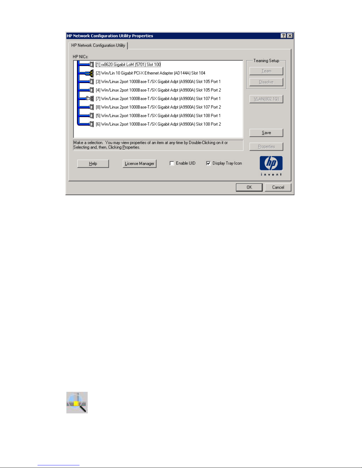
Figure 1-2 NCU Main page
9. Click the License Manager button. The HP Integrity Essentials Network License Manager
displays. For information on how to complete this screen, see the section, “Installing a license
using the License Manager” (page 13).
Running License Manager during a Virus Throttle installation
When you install Virus Throttle, the utility first looks for a valid INP license on the system. If it
does not find one, it automatically launches the HP Integrity Essentials Network License Manager
so you can enter a license key.
To install Virus Throttle:
1. Insert the SmartSetup CD that came with your server.
2. At the License Agreement screen, click Agree.
3. At the HP SmartSetup screen, go to the Software tab.
4. Select your server model number on the left side of the screen.
5. In your server Software screen, under the section, “Configuration and Diagnostic Utilities”,
select HP Virus Throttle.
6. In the Virus Throttle screen, read the Release Notes and installation instructions for this
utility. Then click the Download button, save the installer file to the desired location, and
run it.
7. When the installation finishes, a Virus Throttle tray icon appears on the task bar on the
Windows desktop.
Figure 1-3 Virus Throttle tray icon
8. During installation, if the utility does not identify a valid INP license on the system, you
will see the following message: There is not a valid Integrity Essentials
12 Introduction
Page 13
Intelligent Networking Pack License installed. Would you like to
run the license manager and install one?
9. Click Yes. The HP Integrity Essentials Network License Manager displays. For information
on how to complete this screen, see the section, “Installing a license using the License
Manager” (page 13).
NOTE: After the INP license installs on the system, the Virus Throttle installation
automatically continues. For additional information on Virus Throttle, see the next chapter.
Installing a license using the License Manager
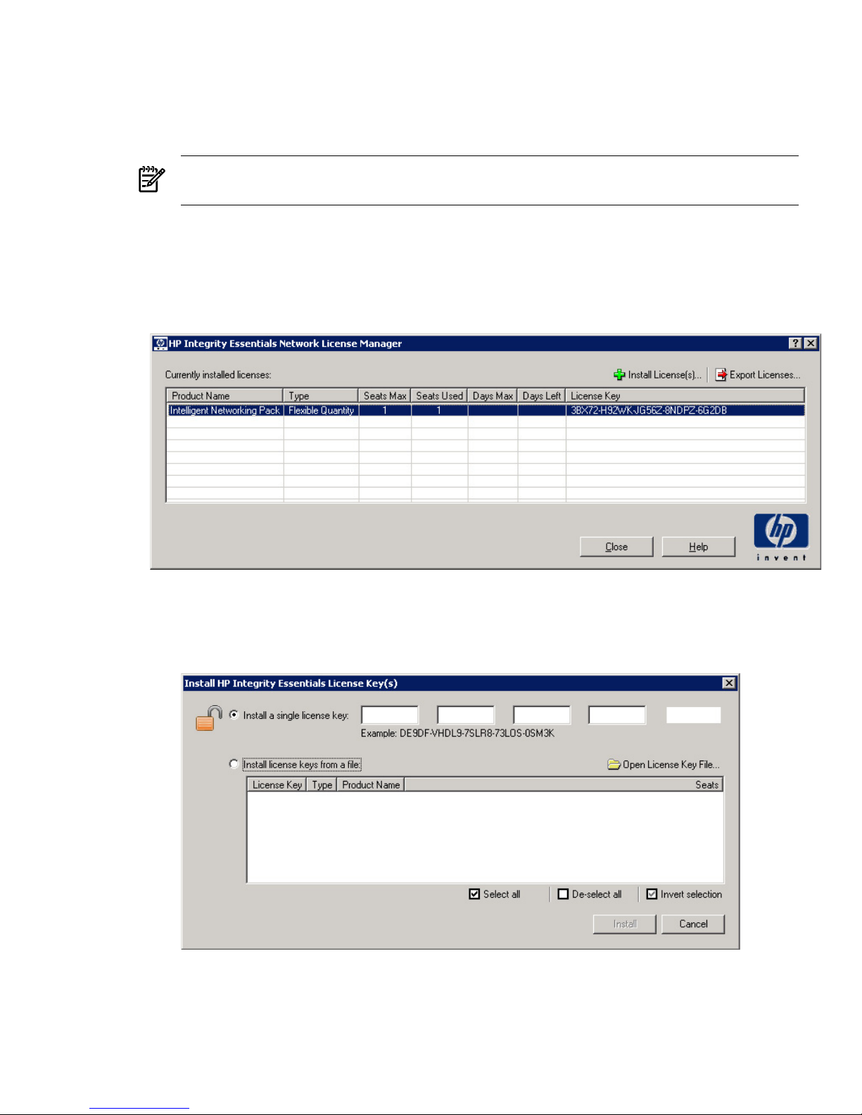
The HP Integrity Essentials Network License Manager allows you to enter new INP licenses as
well as view the status of other licenses on your system.
Figure 1-4 HP Integrity Essentials Network License Manager
To enter a new license from the HP Integrity Essentials Network License Manager main window:
1. Click the Install License(s) button and the Install License Key Window displays.
Figure 1-5 Install License Key window
2. Click the Install a single license key button and enter your unique 25-character license
key string into the five fields (5 characters per field). Then click the Install button to install
the license.
Different ways to install Intelligent Networking Pack licenses 13
Page 14

3. Or, click the Install license keys from a file button. Then click the Open License Key File
button and navigate to a valid keyfile (format = filename.key). Select the desired License
Keys in the window and click Install to install them.
4. A “License Addition Success” message appears, indicating success.
5. Back in the License Manager main window, detailed information about the new license
appears in the Currently Installed Licenses box:
• Product Name: displays the name of the licensed product (Intelligent Networking Pack).
• Type: displays the type of license:
— Single: provides full, unlimited functionality for a single seat (license).
— Flexible Quantity: offers full, unlimited functionality for an unlimited time and
for a specific number of seats purchased, up to 50,000.
— Activation Key Agreement: offers full, unlimited functionality for an unlimited
time. This license represents an expected upper limit on the number of seats, up
to 50,000.
— Demo: provides full, unlimited functionality for a limited time and a specific
number of seats. The license determines the number of days the key allows the
product to function. The days begin counting from the day of first use. The key
can permit more than one instance of the product to run. Demo keys can authorize
up to 250 seats for up to 250 days.
• Seats Max: the total number of licenses authorized for use by this key.
• Seats Used: the number of licenses that are currently used.
• Days Max (displays with Demo key only): the total number of days authorized for use
by this key.
• Days Left (displays with Demo key only): the number of days remaining for this key.
• License Key: displays the license key string.
6. Click Close, and the Intelligent Networking Pack features are enabled on your system. If
you entered the license using the NCU, the NCU Main page displays. If you entered the
license during a Virus Throttle installation, installation of this feature continues. For additional
information on Virus Throttle, see the next chapter.
NOTE: HP recommends that you retain the license key for future reference. The key is needed
for technical support and future upgrades.
Installing licenses using the Network Adapter License Utility
The Network Adapter License utility ships with the HP Network Adapter Configuration Utility
(NCU). It is a Windows-based command line utility that runs at the command line in a Command
Prompt window, or from a Windows command file.
The nalicense command validates an INP license first and then adds it to the system. It also
displays information about licenses already installed on the system.
This utility is installed automatically during installation of the Network Configuration Utility.
Command line usage is exactly the same as in Virus Throttle License Utility (VTLicense), which
is described in the next section. If you want to find out more about nalicense, look at the
documentation installed on your hard drive at C:\HP\network, after you install HP System
Management Homepage (SMH).
Installing licenses using the Virus Throttle License Utility
The Virus Throttle License utility ships with Virus Throttle. It is a Windows-based command
line utility that runs at the command line in a Command Prompt window, or from a Windows
command file.
14 Introduction
Page 15

The VTLicense command validates an INP license first and then adds it to the system. It also
displays information about licenses already installed on the system.
This utility is installed automatically during installation of the Virus Throttle Utility. Command
line usage is exactly the same as in Network License Adapter Utility (nalicense), which is
described in the previous section.
For information about how to use this utility, see the section, “Virus Throttle License Utility”
(page 27).
Installing licenses using the Systems Insight Manager (SIM) License Manager
HP recommends you use the HP Systems Insight Manager (SIM) License Manager for concurrently
installing and monitoring Intelligent Networking Pack licenses on multiple servers. For
information about the HP Systems Insight Manager, go to: http://www.hp.com/go/hpsim.
Different ways to install Intelligent Networking Pack licenses 15
Page 16

16
Page 17

2 Virus Throttle
Viruses typically spread by connecting to as many different machines as possible. Virus Throttle,
a network packet-filtering feature, monitors all outbound connection requests. Virus Throttle
helps to stop the spread of viruses on your system by detecting abnormal or virus like behavior
in the requests. It slows down excessive connection requests to new hosts until you can determine
if they are viral in nature and take action.
How Virus Throttle works
Virus Throttle allows the network infrastructure to stay up and running by slowing traffic on
systems that exhibit high connection rates and frequent connections to new hosts.
When you install Virus Throttle on your system, the Virus Throttle network NDIS filter driver
is inserted into all existing protocol-to-miniport bindings and all network traffic passes through
it. Virus Throttle provides TCP and UDP support. The driver maintains a delay queue of
connection requests for each instance of the network protocol stack and a list of known hosts
that have established connections.
The driver examines all outbound connection requests and determines if the request is for a
known host. If known, the request is passed down the protocol stack as a normal request. If
unknown, the request is added to the delay queue. Periodically, the delay queue is examined
and the oldest request is removed and passed down the protocol stack.
High and low water marks are preset thresholds maintained for the delay queue and are used
to determine when "virus-like" behavior is occurring or has stopped.
• High water mark — When the rate of connection requests exceeds the rate of their removal
from the delay queue, the high water mark in the queue is exceeded, and the driver indicates
virus-like activity.
• Low water mark — When the rate of connection requests slows enough to fall below the
low water mark, the driver indicates that virus-like activity has stopped.
When virus-like activity is detected or has stopped, Virus Throttle sends a Windows Management
Instrumentation (WMI) event notification and, if HP Management agents are installed, a Simple
Network Management Protocol (SNMP) trap is also sent.
Installing Virus Throttle
To install Virus Throttle:
1. Insert the SmartSetup CD that came with your server.
2. At the License Agreement screen, click Agree.
3. At the HP SmartSetup screen, go to the Software tab.
4. Select your server model number on the left side of the screen.
5. In your server Software screen, under the section, “Drivers”, select HP Virus Throttle for
Windows Server 2003 on Itanium-based systems.
6. In the Virus Throttle screen, read the Release Notes and installation instructions for this
utility. Then click the Download button, save the installer file to the desired location, and
run it.
7. Click Install at the HP Package Setup screen to begin the installation.
8. When the installation finishes, a Virus Throttle tray icon appears on the task bar on the
Windows desktop. Use this icon to open the Virus Throttle Status and Configuration Utility.
How Virus Throttle works 17
Page 18
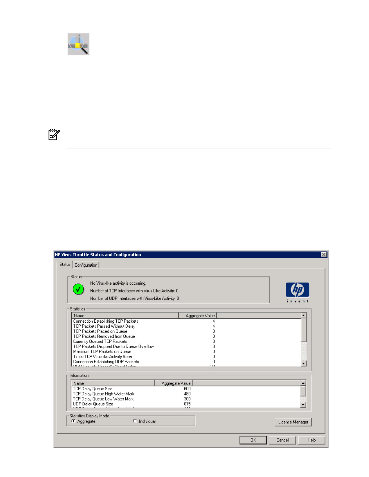
Figure 2-1 Virus Throttle tray icon
9. During installation, if the utility does not identify a valid INP license on the system, you
will see the following message: There is not a valid Integrity Essentials
Intelligent Networking Pack License installed. Would you like to
run the license manager and install one?
10. Click Yes. The Integrity Essential Intelligent Networking Pack License Manager displays.
For information on how to complete this screen, see the section, “Installing a license using
the License Manager” (page 13).
NOTE: After the INP license installs on the system, the Virus Throttle installation
automatically continues.
Using Virus Throttle
After you install Virus Throttle, the parameters for the filter driver are set to defaults. Any changes
made to those parameters are made to all active instances of the Virus Throttle filter driver.
To open the Virus Throttle Status and Configuration Utility:
1. Close the Network Configuration Utility, if it is open. Both utilities cannot run at the same
time (an error message displays if you try to run them simultaneously).
2. Double-click the Virus Throttle Tray icon to launch it. The main window displays, defaulting
to the Status tab.
Figure 2-2 Virus Throttle Status tab
18 Virus Throttle
Page 19
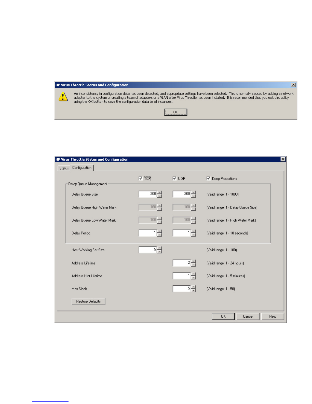
When a new adapter is installed on the system or a new team or VLAN is created, the parameters
for that interface are set to the default settings. When the Virus Throttle Status and Configuration
Utility runs, it looks for inconsistencies in the settings for all the active instances, and prompts
you to update these settings if inconsistencies are found.
For example, if the default parameters are changed and a new adapter is added, the parameters
for that adapter will be inconsistent until the utility runs and prompts you to change them. If
inconsistencies are found when Virus Throttle launches, the following message appears:
Figure 2-3 Virus Throttle inconsistency message
Click OK, and the Configuration Tab displays, allowing you to review (or change) and then save
the settings for all active instances.
Figure 2-4 Virus Throttle Configuration tab
After making your changes, click OK to save the settings.
If you click Cancel even when there are inconsistent settings that should be changed, the following
message appears.
Using Virus Throttle 19
Page 20

Figure 2-5 Virus Throttle inconsistency message
If you click Yes here, the utility closes and the inconsistent settings remain. If you click No, the
Configuration Tab displays again so you can change your settings and save them.
Configuring Virus Throttle parameters
The Configuration tab shows the current delay queue and host settings, and lets you configure
them for all active instances of the Virus Throttle filter driver. You can configure the settings for
Transmission Control Protocol (TCP) packets and User Datagram Protocol (UDP) packets.
You can configure the following parameters:
• Delay Queue Size: controls the maximum number of delayed connection requests in the
queue for each instance of the filter driver. Requests over the queue size are dropped. The
default is 200 delayed connection requests. The valid range is 1 - 1000.
• Delay Queue High Water Mark: controls the number of connection requests in the delay
queue at which virus-like activity is considered to be occurring for each instance of the filter
driver. The default is 160 connection requests. The valid range is 1 - Delay Queue Size.
• Delay Queue Low Water Mark: controls the number of connection requests in the delay
queue below which virus-like activity is considered to be stopped. The default is 100
connection requests. The valid range is 1 - High Water Mark.
• Delay Period: controls the rate at which connection requests are removed from the delay
queue and passed down the protocol network stack. The default is 1 second. The valid range
is 1 - 10 seconds.
• Host Working Set Size: controls the number of known machines to which connections are
established without delay. When a new connection is made, the oldest member of the working
set is replaced with the new host. The default is 5 hosts. The valid range is 1 - 100. This
setting is only supported for TCP packets.
• Address Lifetime: controls the number of timer intervals that an address remains in the
working set after the last outbound packet was sent to it. The default is 2 hours. The valid
range is 1–100. This setting is only supported for UDP packets.
• Address Hint Lifetime: controls the number of timer intervals that an address is kept in the
working set after the last inbound packet was received from it. The default is 1 minute. The
valid range is 1–5. This setting is only supported for UDP packets.
• Max Slack: Controls the number of known machines to which connections are established
without delay. The default is 5 hosts. The valid range is 1–50. This setting is only supported
for UDP packets.
The following controls are available:
• TCP: enables configuration of delay queue and host settings for Transmission Control
Protocol (TCP) packets.
• UDP: enables configuration of delay queue and host settings for User Datagram Protocol
(UDP) packets.
Keep Proportions: provides a way to keep the high and low water mark values at a preset
percentage of the delay queue size for TCP and UDP outbound connection request. When
Keep Proportions is not selected, the delay queue high and low water mark values can be
changed. When Keep Proportions is selected, the delay queue high and low water mark
values cannot be changed, and are automatically preset at 80% of the delay queue size for
the high water mark and 50% of the delay queue size for the low water mark.
20 Virus Throttle
Page 21
• Restore Defaults: restores all values to their default values.
• OK: processes all changes made in the current session and closes the Virus Throttle Status
and Configuration Utility.
• Cancel: cancels any selections made in the current session and closes the Virus Throttle
Status and Configuration Utility.
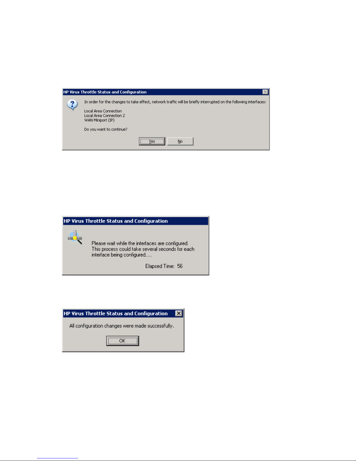
When you click OK to process your changes, the following message displays.
Figure 2-6 Virus Throttle interruption message
Click Yes here. Your configuration changes are written to the registry area for each active instance
of the filter driver. Each one must be stopped and restarted so the new parameters can be read.
This results in a brief interruption of network traffic.
The following message displays while the active instances are stopped and started, to read the
new parameters from the registry.
Figure 2-7 Virus Throttle wait message
When configuration finishes, the following message appears.
Figure 2-8 Virus Throttle success message
Click OK. The parameters are changed for all the active instances of the Virus Throttle filter
driver, and the Virus Throttle Status and Configuration Utility closes.
Monitoring Virus Throttle status
The Status Tab shows overall status, statistics, and delay queue information. Statistics and delay
queue information can be viewed in either Aggregate mode (summarizes all active instances of
the Virus Throttle filter driver) or Individual mode (summarizes per instance). The default mode
is Aggregate.
Using Virus Throttle 21
Page 22
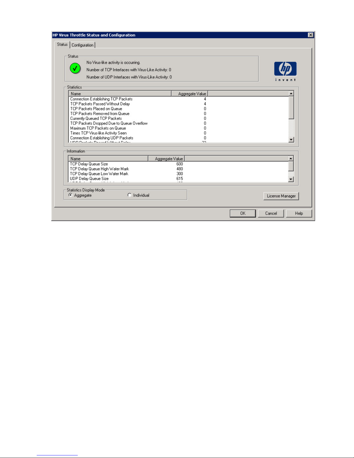
Figure 2-9 Virus Throttle Status tab
• Status: displays the current state and number of interfaces with virus-like activity since the
Virus Throttle filter drivers were initialized.
— No Virus-like activity is occurring: no virus-like activity is currently detected and none
has been detected.
— Virus-like activity is not occurring, but has occurred in the past: no virus-like activity
is currently detected, but virus-like activity has been detected.
— Virus-like activity is currently occurring: virus-like activity is currently detected by
at least one instance of the filter drivers.
— Number of TCP Interfaces with Virus-Like Activity: number of TCP interfaces that
are currently displaying virus-like activity.
— Number of UDP Interfaces with Virus-Like Activity: number of UDP interfaces that
are currently displaying virus-like activity.
• Statistics: displays statistics on an aggregate or per-instance basis since the filter drivers
were initialized.
— Connection Establishing TCP Packets: number of TCP connection packets seen since
filter driver initialization.
— TCP Packets Passed Without Delay: number of TCP connection packets that were
passed without a delay because the target was a known host since filter driver
initialization.
— TCP Packets Placed on Queue: number of TCP connection packets queued since filter
driver initialization.
— TCP Packets Removed from Queue: number of TCP connection packets removed from
the delay queue since filter driver initialization.
— Currently Queued TCP Packets: number of TCP connection packets currently on the
delay queue.
22 Virus Throttle
Page 23

— TCP Packets Dropped Due to Queue Overflow: number of TCP packets that were
dropped due to the delay queue being full since filter driver initialization.
— Maximum TCP Packets on Queue: maximum number of TCP packets on the queue
since filter driver initialization.
— Times TCP Virus-like Activity Seen: number of times virus-like activity was detected
since TCP filter driver initialization.
— Connection Establishing UDP Packets: number of UDP connection packets seen since
filter driver initialization.
— UDP Packets Passed Without Delay: number of UDP connection packets that were
passed without a delay because the target was a known host since filter driver
initialization.
— UDP Packets Placed on Queue: number of UDP connection packets queued since filter
driver initialization.
— UDP Packets Removed from Queue: number of UDP connection packets removed
from the delay queue since filter driver initialization.
— Currently Queued UDP Packets: number of UDP connection packets currently on the
delay queue.
— UDP Packets Dropped Due to Queue Overflow: number of UDP packets that were
dropped due to the delay queue being full since filter driver initialization.
— Maximum UDP Packets on Queue: maximum number of UDP packets on the queue
since filter driver initialization.
— Times UDP Virus-like Activity Seen: number of times virus-like activity was detected
since UDP filter driver initialization.
• Information: displays the current queue settings.
— TCP Delay Queue Size: the maximum number of TCP connection requests in the delay
queue for each instance.
— TCP Delay Queue High Water Mark: the number of TCP connection requests in the
delay queue where virus-like activity is indicated.
— TCP Delay Queue Low Water Mark: the number of TCP connection requests in the
delay queue below which virus-like activity is no longer indicated.
— UDP Delay Queue Size: the maximum number of UDP connection requests in the
delay queue for each instance.
— UDP Delay Queue High Water Mark: the number of UDP connection requests in the
delay queue where virus-like activity is indicated.
— UDP Delay Queue Low Water Mark: the number of UDP connection requests in the
delay queue below which virus-like activity is no longer indicated.
The following controls are available:
• Statistics Display Mode: sets the type of values displayed.
— Aggregate: displays a summary of all instances.
— Individual: displays values on a per-instance basis.
• License Manager: opens the License Manager dialog box, for adding new INP licenses to
the system or viewing currently installed licenses.
• OK: processes all changes made in the current session and closes the Virus Throttle Status
and Configuration Utility.
• Cancel: cancels any changes made in the current session and closes the Virus Throttle Status
and Configuration Utility.
• Help: launches the context-sensitive Help file.
Unbinding Virus Throttle from a network connection
To unbind Virus Throttle from a network connection:
Using Virus Throttle 23
Page 24
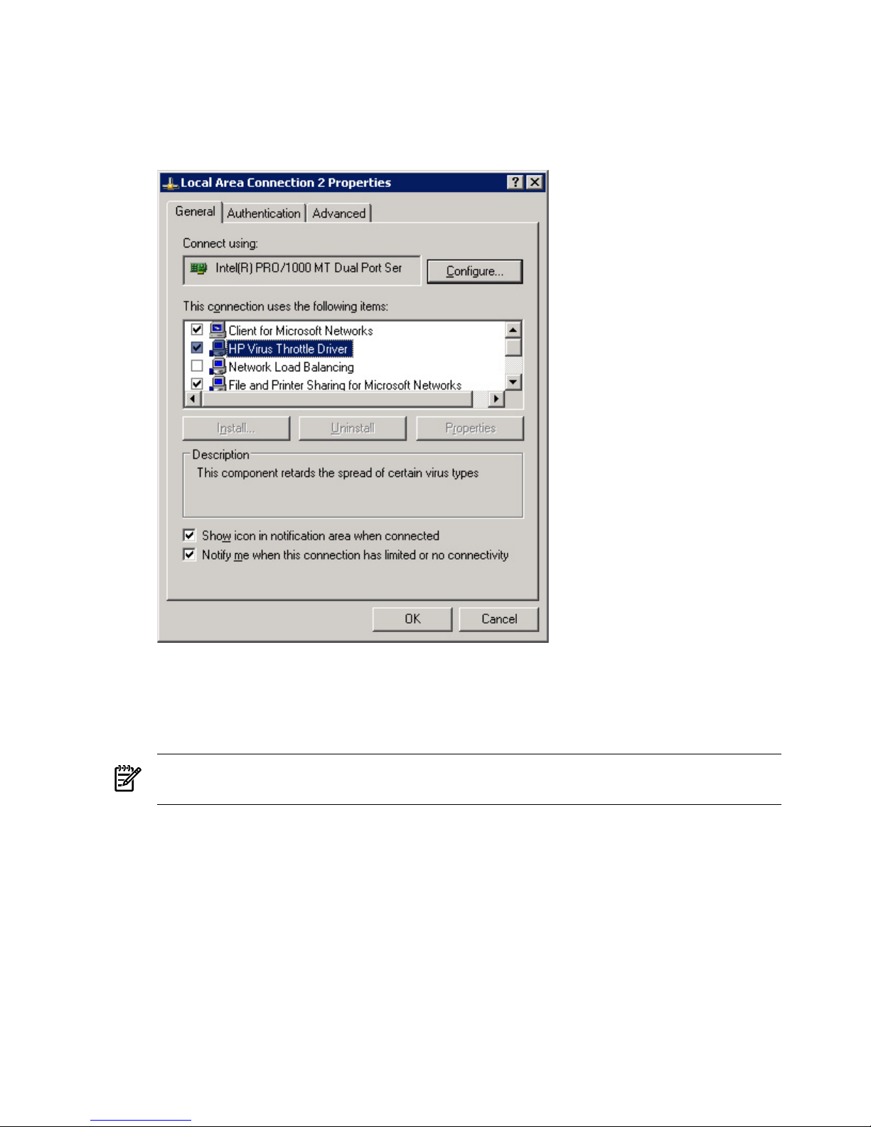
1. In the Windows Control Panel, double-click the Network Connections icon.
2. In the Network Connections window, right-click on the desired LAN connection icon and
select Properties from the drop-down list. The Local Area Connection Properties window
displays.
Figure 2-10 Local Area Connection Properties
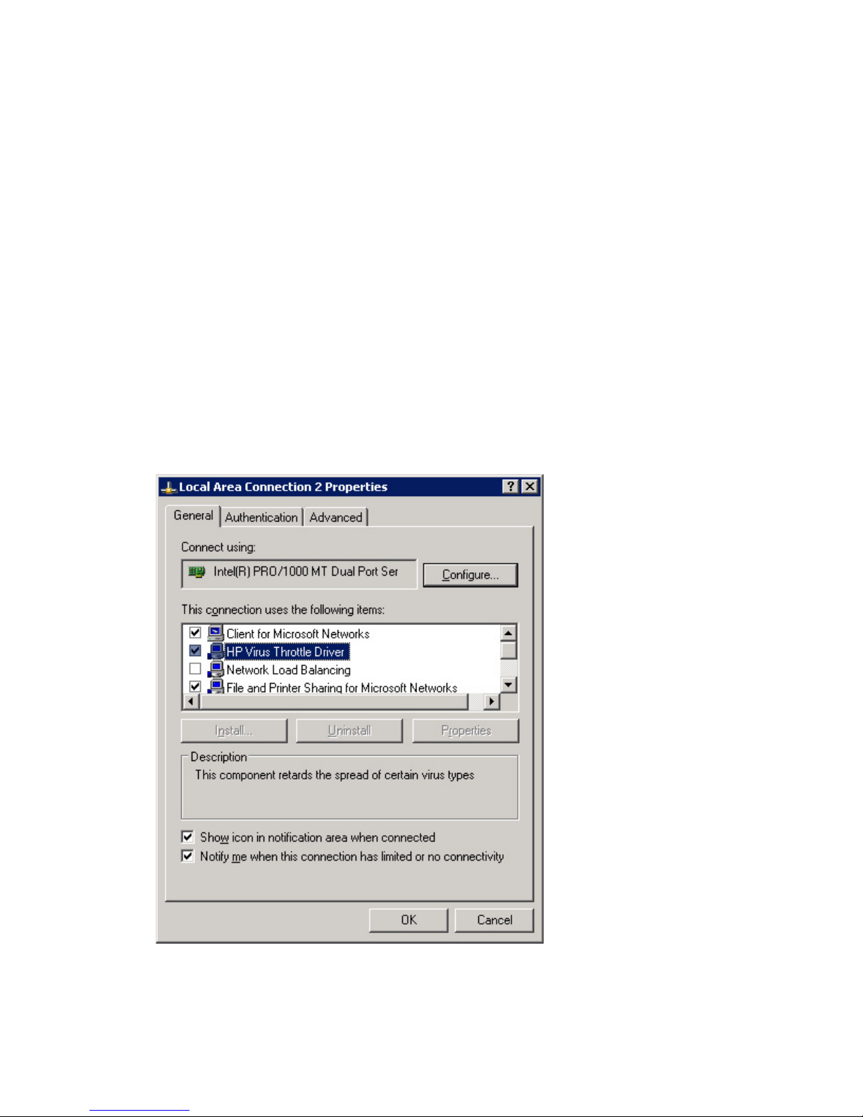
3. On the General tab, in the box labeled “This connection uses the following items”, click to
clear the checkmark in front of the HP Virus Throttle Driver item.
4. Click OK to implement the change and close the Network Connections window for that
connection. This process does not require a system reboot.
NOTE: This process does not remove Virus Throttle from the system. It removes Virus
Throttle from that specific connection. It does not affect any other network connections.
5. To verify Virus Throttle was successfully removed, open the Connection Properties window
again and confirm that the Virus Throttle checkbox is cleared. In addition, the change should
be reflected on the Status tab in the Virus Throttle Status and Configuration Utility. On the
Status tab, look in the Information box to see a list of all network connections that Virus
Throttle is currently bound to, and verify the connection name no longer appears in the list
(to see individual network connections on the Status tab, you must select the Individual
setting under “Statistics Display Mode”).
24 Virus Throttle
Page 25
NOTE: To unbind Virus Throttle from a specific network interface card (NIC) you must
first identify the physical NIC. This means you have to know the hardware layout of your
system. Once you've identified the physical NIC, you must determine the Network
Connection associated with it and unbind Virus Throttle from that connection, as described
previously.
Re-binding Virus Throttle to a network connection
To re-bind Virus Throttle to a network connection where it was previously unbound:
1. In the Windows Control Panel, double-click the Network Connections icon.
2. In the Network Connections window, right-click on the desired LAN connection icon and
select Properties from the drop-down list. The Local Area Connection Properties window
displays.
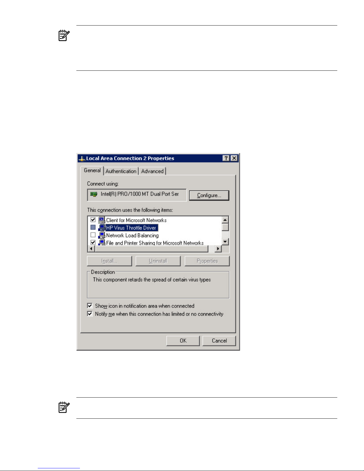
Figure 2-11 Local Area Connection Properties
3. On the General tab, in the box labeled “This connection uses the following items”, click to
select the HP Virus Throttle Driver item.
4. Click OK to implement the change and close the Network Connections window for that
connection. This process does not require a system reboot.
NOTE: This process binds Virus Throttle to this specific connection only. It does not affect
any other network connections.
5. To verify Virus Throttle was successfully added, open the Connection Properties window
again and confirm that the Virus Throttle checkbox is selected. In addition, the change should
be reflected on the Status tab in the Virus Throttle Status and Configuration Utility. On the
Using Virus Throttle 25
Page 26
Status tab, look in the Information box to see a list of all network connections that Virus
Throttle is currently bound to, and verify the connection name appears in the list (to see
individual network connections on the Status tab, you must select the Individual setting
under “Statistics Display Mode”).
Removing network interface cards from a Virus Throttle system
To remove a NIC from systems where Virus Throttle is installed:
1. First, you must unbind Virus Throttle from the network connection associated with the
physical card. For instructions on how to do this, see “Unbinding Virus Throttle from a
network connection” (page 23).
2. Once Virus Throttle is unbound from the network connection, only then should you
physically remove the NIC from the system.
Removing Virus Throttle from the system
To completely remove Virus Throttle from the system:
1. In the Windows Control Panel, double-click the Network Connections icon.
2. In the Network Connections window, right-click on any of the LAN connection icons (it
doesn’t matter which one) and select Properties from the drop-down list. The Local Area
Connection Properties window displays.
Figure 2-12 Local Area Connection Properties
3. On the General tab, in the box labeled “This connection uses the following items”, click the
HP Virus Throttle Driver item to highlight it. Then click the Uninstall button.
4. A pop-up message indicates that Virus Throttle will be removed from all network connections.
Click Yes to continue.
26 Virus Throttle
Page 27

5. The removal process may take awhile, depending on the number of connections to which
Virus Throttle was bound. When the process finishes you are prompted to reboot. Click Yes
to continue. Removal is not complete until the system restarts.
6. After the restart, verify that Virus Throttle was removed by navigating to the Local Area
Connection Properties window again. On the General tab, in the box labeled “This connection
uses the following items”, confirm that the HP Virus Throttle item is no longer listed. In
addition, the Virus Throttle taskbar icon should not appear in the taskbar .
Virus Throttle License Utility
As mentioned in the previous chapter, you can use HP Virus Throttle License Utility (VTLicense)
to add INP licenses to your Integrity server or display information about existing licenses. This
utility runs at the command line in a Command Prompt window, or from a Windows command
file.
The VTLicense command determines if the license is a valid Integrity Essentials Intelligent
Networking Pack license, and if it is valid, adds it to the system. It then writes the results to a
default log file (nalicense.log) in the %SystemDrive%\cpqsystem\log directory. All messages,
whether successful or error, are written both to the stdout/stderr and to the log file. Each time
you run the utility the log file is appended with a date and time stamp. You can override the
default log file location by specifying an alternate location with the /l option.
The utility parses the command line and if the license and the action are valid, performs the
desired action. Because this is a command line application it is appropriate for inclusion in the
GuiRunOnce section of the unattend.txt file, and can be used to add an Integrity Essentials
Intelligent Networking Pack license during installation of the operating system.
The Virus Throttle License Utility is not installed or functional until you do one of the following:
• Install Virus Throttle (see “Installing Virus Throttle” (page 17)) using the Smart Component
Install option. Then you can run VTLicense from the %systemroot%\system32 directory.
• Use the Smart Component Extract option (instead of the Install option), and run VTLicense
from the extraction directory.
Command line syntax
Use one of the following formats at the command line:
VTLicense add <license string> [/l <log-file>] [/? | /help]
or:
VTLicense display [/l <log-file>] [/? | help] [/M]
Command line arguments
Use the following command line arguments:
Table 2-1 Command line arguments
FunctionArgument
Identifies the Integrity Essentials Intelligent Networking Pack license string
to add to the system and is only valid with the addsubcommand. The license
string must be in dash-separated form:
“AAAAA-BBBBB-CCCCC-12345-12345”
<license string>
Specifies location to write success/error message (optional).
/l <log-file>
Displays utility usage (optional).
/?
Virus Throttle License Utility 27
Page 28

Table 2-1 Command line arguments (continued)
FunctionArgument
Displays utility usage (optional).
/help
Prints license information in a format capable of being parsed by machine
(optional).
/M
Return codes
The following return codes may display:
Table 2-2 Return codes
DescriptionCode
Success.
0
Duplicate license exists.
1
Invalid Integrity Essentials Intelligent Networking Pack license.
2
Unrecognized Integrity Essentials Intelligent Networking Pack license.
3
Usage error.
4
Command line examples
The following are valid VTLicense command line examples:
Example #1:
VTLicense add <license string>
What it does:
Adds the provided license to the system and upon successful operation writes the following
message to both stdout and to the default log file:
Mon Sep 15 15:42:14 2003: Adding License “AAAAA-BBBBB-CCCCC-12345-12345”.
Success
Example #2:
VTLicense display /m /l license.txt
What it does:
Displays all valid licenses on the system and upon successful operation writes the following
message to both stdout and to the license.txt file located in the same directory as VTLicense.exe:
License String;Product Name;Ver;Type;Seats
Used;Days;Permitted;Left;AAAAA-BBBBB-CCCCC-12345-12345; Intelligent
Networking Pack;1;Demo;1;N/A;90;35
Example #3:
VTLicense display /l license.txt
What it does:
Displays all valid licenses on the system and upon successful operation writes the following
message to both stdout and to the license.txt file located in the same directory as VTLicense.exe:
License Details:
License #1
License String: AAAAA-BBBBB-CCCCC-12345-12345
Product Name: Intelligent Networking Pack
Product Version: 1
Product Type: Flexible
Seats Permitted: 1
28 Virus Throttle
Page 29

Seats Used: 1
Days Permitted:
Days Left: Unlimited
Virus Throttle License Utility 29
Page 30

30
Page 31

3 Advanced Networking Features
With an Intelligent Networking Pack license installed on your system, you can enable six
additional team types and three advanced redundancy types. This chapter describes how to
activate and configure these features.
Advanced team types include:
• Switch-assisted Dual Channel Network Fault Tolerance
• Switch-assisted Dual Channel Network Fault Tolerance and Preference Order
• 802.3ad Dynamic Dual Channel Network Fault Tolerance
• 802.3ad Dynamic Dual Channel Network Fault Tolerance and Preference Order
• Switch-assisted Dual Channel Load Balancing
• 802.3ad Dynamic Dual Channel Load Balancing
Advanced redundancy types include:
• Active Path Failover
• Fast Path Failover
• Router Path Failover
Advanced team types
The advanced team types provide a selection of fault-tolerant and load-balancing features,
including Network Fault Tolerance (NFT), Transmit Load Balancing (TLB), and Switch-assisted
Load Balancing (SLB).
Dual Channel Network Fault Tolerance
Dual Channel NFT provides the safety of additional backup-links between the server and
hub/switch. It is implemented with one channel team providing a primary adapter and another
channel team providing a secondary, backup adapter. During normal operations, if the adapters
in the primary team fail, a link to one of the adapters in the secondary, backup team automatically
takes over.
Four types of Dual Channel NFT teams can be configured:
• Switch-assisted Dual Channel NFT
• Switch-assisted Dual Channel NFT and Preference Order
• 802.3ad Dynamic Dual Channel NFT
• 802.3ad Dynamic Dual Channel NFT and Preference Order
Switch-assisted Dual Channel NFT
Switch-assisted Dual Channel NFT requires a minimum of two adapters in a channel team and
a minimum of one adapter per group. When you select Switch-assisted Dual Channel NFT, the
Team Members window becomes team members grouping and displays two windows labeled
Group 0 and Group 1.
Switch-assisted Dual Channel NFT and Preference Order
Provides the same options as Switch-assisted Dual Channel Network Fault Tolerance except it
offers the additional option to select the priority order of the group (Group 0 or Group 1) used
for the primary and secondary teams.
802.3ad Dynamic Dual Channel NFT
Dynamic Dual Channel NFT requires a minimum of two adapters in a channel team and a
minimum of one adapter per group. All team members within each group are dynamically placed
into a porttrunk/ channel by dynamic LACP agreement with the switch. It provides the safety
of additional backup links between the server and hub/switch. One channel team provides a
primary adapter and another channel team provides a secondary, backup adapter.If the adapters
Advanced team types 31
Page 32

in the primary team fail, a link to one of the adapters in the secondary, backup team automatically
takes over.
802.3ad Dynamic Dual Channel NFT and Preference Order
Provides the same options as 802.3ad Dynamic Dual Channel NFT except it offers the additional
option of setting the priority order of the adapters that are used in the primary and secondary
teams.
Dual Channel Load Balancing
Dual Channel Load Balancing allows the creation of two teams, called groups, inside of a single
team. Each group is assigned one or more teamed ports. Each group can also be connected to a
different switch to provide switch fault tolerance. Full inbound and outbound load balancing is
provided across both groups. Should any group completely fail, caused by a failure of all teamed
ports in the group or by a failure of the group's switch, the team remains available through the
other group.
Two types of Dual Channel Load Balancing teams can be configured:
• Switch-assisted Dual Channel Load Balancing teams
• 802.3ad Dynamic Dual Channel Load Balancing team
Switch-assisted Dual Channel Load Balancing
The Switch-assisted Dual Channel Load Balancing team type allows you to define one group of
team members to be treated as a Switch-assisted Load Balancing (SLB) group to one switch, and
a second group of team members to be treated as an SLB group to a second switch.
With Switch-assisted Dual Channel Load Balancing, all transmit packets are load balanced among
all team members based on a load balancing algorithm in the teaming device driver. The receive
packets are load balanced among all team members by both the switch and the team. If a failure
of any team member occurs, the packets are load balanced among the remaining adapters.
There must be a minimum of two adapters in a Switch-assisted Dual Channel Load Balancing
team with a minimum of one adapter in each group. Only Gigabit adapters can be used for
Switch-assisted Dual Channel Load Balancing.
Fast Path Failover, Active Path Failover, and Router Path Failover are available on Switch-assisted
Dual Channel Load Balancing teams.
802.3ad Dynamic Dual Channel Load Balancing
With 802.3ad Dynamic Dual Channel Load Balancing teams, team members are dynamically
placed into groups. All team members within each group are dynamically placed into a port
trunk/channel by dynamic protocol agreement, Link Aggregation Control Protocol (LACP), with
the switch. A failure of a team member to negotiate joining a port trunk or channel with the
switch is treated as an error and that team member is considered failed.
All transmit packets are load balanced among all team members based on a load balancing
algorithm in the teaming device driver. The receive packets are load balanced among all team
members by the switch. If a failure of any team member occurs, the packets are load balanced
among the remaining adapters.
There must be a minimum of two adapters in a dual channel team. Fast Path Failover, Active
Path Failover, and Router Path Failover are available on 802.3ad Dynamic Dual Channel Load
Balancing teams.
Configuring a dual channel team
To configure a dual channel team:
1. On the NCU Main page, highlight the team.
2. Click Properties. The Teaming Controls tab displays, showing the team name, team type,
transmit load balancing method, and team membership.
32 Advanced Networking Features
Page 33
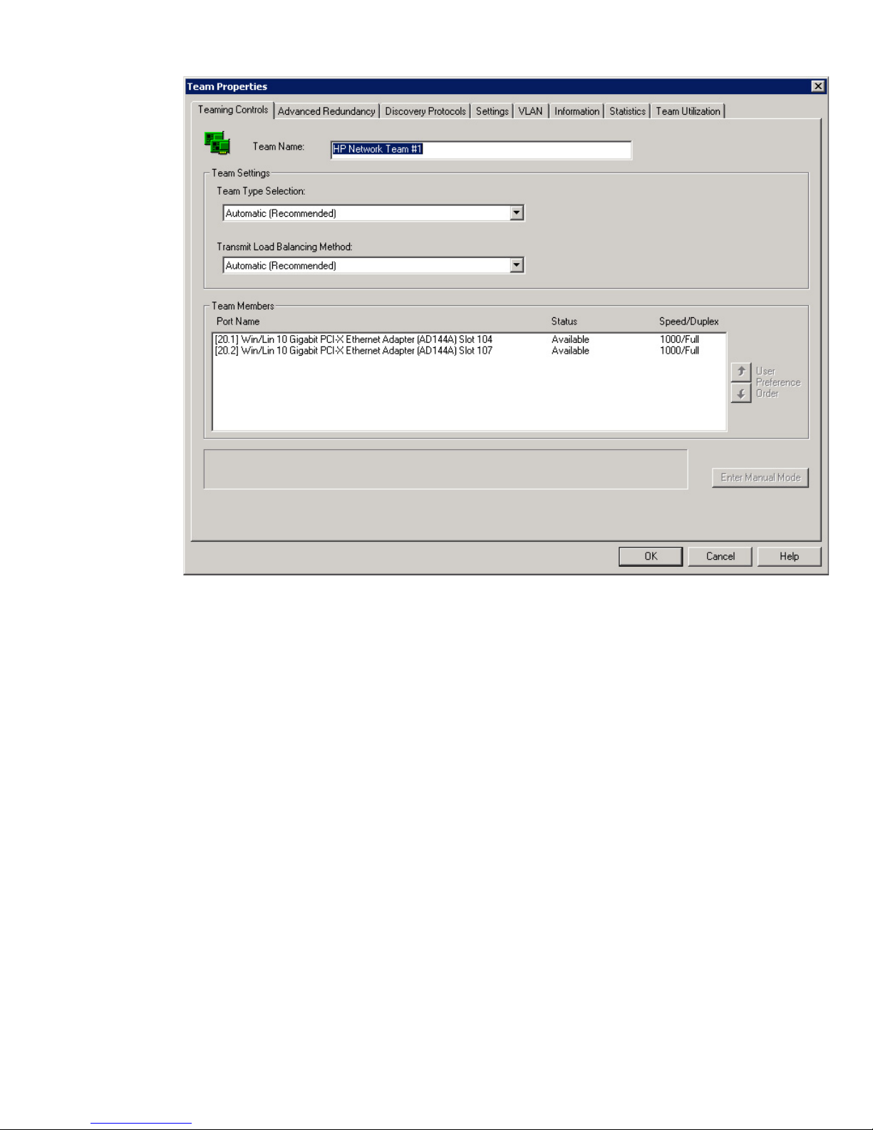
Figure 3-1 Teaming Controls tab
3. A unique character string identifying this team displays in the Team Name field. This name
displays as the device name in the Network and Dial-up Connections page and on the NCU
Main page.
4. Select a Dual Channel team type from the Team Type Selection list.
Dual Channel team type options include:
• Switch-assisted Dual Channel Network Fault Tolerance
• Switch-assisted Dual Channel Network Fault Tolerance and Preference Order
• 802.3ad Dynamic Dual Channel Network Fault Tolerance
• 802.3ad Dynamic Dual Channel Network Fault Tolerance and Preference Order
• Switch-assisted Dual Channel Load Balancing or 802.3ad Dynamic Dual Channel
Load Balancing
5. Select the Transmit Load Balancing Method for the team.
Transmit Load Balancing Methods include:
• Automatic (Recommended): default setting. Teaming driver selects the load balancing
mechanism based on the packet type.
• TCP Connection: load balances transmitted TCP packets using the TCP connection
information.
• Destination IP Address: load balances transmit IP packets using the last four bits of
the destination IP Address.
Advanced team types 33
Page 34
• Destination MAC Address: load balances transmit IP packets using the last four bits
of the destination MAC Address.
• Round Robin: (Packet order not guaranteed.) load balances transmit packets among
all team members. A packet is sent on one team member, the next packet is sent out on
the next team member, and so on. When the last team member is utilized, the rotation
begins again.
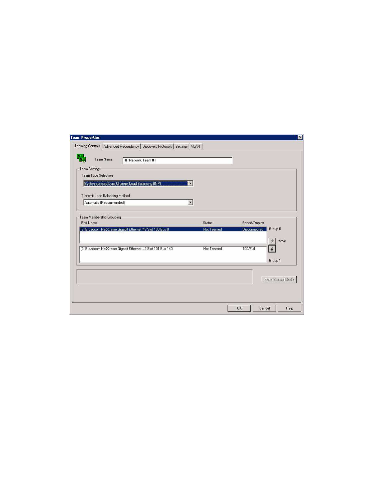
6. If you select Switch-assisted Dual Channel Network Fault Tolerance or Switch-assisted Dual
Channel Load Balancing as the team type, the Team Members box displays two sections
labeled Group 0 and Group 1. Click the User Preference Order up and down arrows to assign
the members to be in Group 0 and the members to be in Group 1. There must be a minimum
of two adapters in a dual channel team with a minimum of one adapter in each group.
Figure 3-2 Teaming Controls tab — showing Group 0 and Group 1 sections
If you select 802.3ad Dynamic Dual Channel Network Fault Tolerance or 802.3ad Dynamic
Dual Channel Load Balancing as the team type, the User Preference Order up and down
arrows are disabled. Team members are placed dynamically into groups.
If you select 802.3ad Dynamic Dual Channel Network Fault Tolerance and Preference Order
you can select the preference order for the team.
If you select Switch-assisted Dual Channel Network Fault Tolerance and Preference Order,
you can assign the members to be in Group 0 and the members to be in Group 1 and you
can select the preference order for the group (Group 0 or Group 1).
Team membership information includes:
• Port Name: displays the network adapter number, slot, and port location for the team
member.
• Status: displays the status of the member within the context of the team. Not all status
types apply for every team type.
— Available — the team member is functioning normally.
— Not Teamed — the adapter is not part of the team. The most likely cause is adding
an adapter to the team but not applying the change.
34 Advanced Networking Features
Page 35

— Unknown — the team member's status could not be determined.
— Wire Fault — the member does not have a link.
— Not Joined — the member cannot be joined in the team because it has an
incompatible setting. The most likely cause is changing a parameter for a team
member using the local area connection property sheet.
— Degraded (Fast Path) — the team member and no other team members can receive
Bridge Protocol Data Units (BPDUs). Because all team members have equal Fast
Path status, the team member is still in use by the team.
— Degraded (Active Path) — the team member and other team members cannot reach
the echo node. Because all team members have equal Active Path status, the team
member is still in use by the team.
— Degraded (Rx Path) — the team member is not receiving packets, and no other
team member is receiving packets. Because all team members are equal, the team
member is still in use by the team.
— Degraded (Multiple) — the team member has multiple degraded conditions.
— Degraded (Router Path) — the team member and no other team members can
receive router protocol frames. Because all team members have equal router path
status, the team member is still in use by the team.
— Failed (Active Path) — the member is not receiving replies from the configured
echo node.
— Failed (Split LAN:FP) — team members are receiving BPDUs from different
networks.
— Failed (Fast Path) — no team member is receiving correct BPDUs.
— Failed (LACP) — the team member failed to establish an LACP channel.
— Failed (LACP Standby) — the team member has failed because the team has more
members than the switch supports in the LACP protocol. The port is blocked by
the switch.
— Failed (Rx Path) — the team member is not receiving packets.
— Failed (Tx Path) — a failure occurred while attempting to send a packet to the team
member.
— Failed (Multiple) — the team member has multiple failed conditions.
— Failed (Router Path) — the team member is not receiving router protocol frames.
— Failed (Split LAN: RP) — the team members are receiving router protocol frames
from different networks.
• Speed/Duplex — displays the current speed/duplex setting of the team member.
7. Click OK to save all changes. The NCU Main page appears.
8. Click OK on the NCU Main page to apply changes.
Advanced redundancy types
Basic redundancy features, standard with HP server adapter networking software, include link
loss, transmit path validation, and receive path validation. These basic redundancy mechanisms
monitor each teamed port for link, the ability to transmit a frame, and the ability to receive a
frame.
Three advanced redundancy features, Active Path Failover, Fast Path Failover, and Router Path
Failover are available through the INP. These features allow servers to proactively adapt to
networking infrastructure problems.
These features are available for all team types except Switch assisted Load Balancing with Fault
Tolerance (SLB) and 802.3ad Dynamic with Fault Tolerance teams.
Active Path Failover
Advanced redundancy types 35
Page 36

Active Path Failover allows a ProLiant server to predict and bypass failed network paths through
use of a user assigned echo node. An echo node is a device on the network with which connectivity
is required. Periodically, each team member transmits an Address Resolution Protocol (ARP)
request packet to the echo node. If a response is not received from the echo node within a set
timeout period, the team member is marked as failed.
If Active Path Failover is enabled, you must enter a valid IP address for the echo node. In addition,
you can specify the MAC address of the echo node, which allows the echo node packets to be
unicast to the echo node. If no Echo Node MAC address is provided, the echo node packets are
broadcast.
Two types of echo node request probes are available:
• Community Address ARP — (Recommended) Community Address ARP is a newer method
that uses a standard ARP to test connectivity. It works for all devices designated as the echo
node including routers, Hot Standby Routing Protocol (HSRP) devices, and Linux servers.
If Community Address ARP is selected, you must enter the IP address to be used for the
community probe. You can also configure the MAC address to be used, or use the default
MAC address.
• Directed ARP — Directed ARP tests connectivity with the echo node device using a modified
ARP frame. This method works for most switches or servers that are designated as the echo
node. It is not recommended for routers or Linux servers that are designated as the echo
node.
Fast Path Failover
Fast Path Failover allows a ProLiant server to determine the fastest path to the core network (or
the root bridge) in addition to detecting full connectivity loss. Fast Path Failover examines the
path cost information contained in the Spanning Tree Bridge Protocol Data Unit (BPDU) frames
and determines which switch is the best one to use for the team's primary port.
When configuring Fast Path Failover, you must select which Spanning Tree Protocol (STP) type
to use. The two predominate STP types are as follows:
• IEEE 802.1D — because IEEE 802.1D is VLAN unaware, it is not necessary to configure Fast
Path Failover to listen to VLAN.
• Cisco PVST+ — allows you to select the VLAN ID to be used for Fast Path Failover
monitoring. (Refer to “Configuring VLAN IDs.” section)
Router Path Failover
Router Redundancy Protocols (HSRP, VRRP) allow you to set up two or more routers into a
single router group, which acts as a backup for a virtual router. At any given time, only one
router is designated as the active router, which takes up the functionality of the router. If the
active router fails, a second router or standby router assumes the role of the active router. If the
standby router fails or becomes the active router, then another router is elected as the standby
router.
The Router Path Failover ensures the team's connectivity to the active router. The router protocol,
as selected by the user, defines the method used to select the active router by periodically
exchanging multicast frames amongst routers in a router group. The NCU teaming software
monitors these multicast frames to validate an active path to the active router in the router group.
When configuring Router Path Failover, you must select which router protocol to use. The two
protocols available are as follows:
• HSRP — Cisco Hot Standby Router Protocol
• VRRP — Virtual Router Redundancy Protocol
Configuring Active Path Failover
Active Path Failover is enabled through the Team Properties Advanced Redundancy tab. This
feature is disabled if a valid INP license is not installed on the system.
36 Advanced Networking Features
Page 37
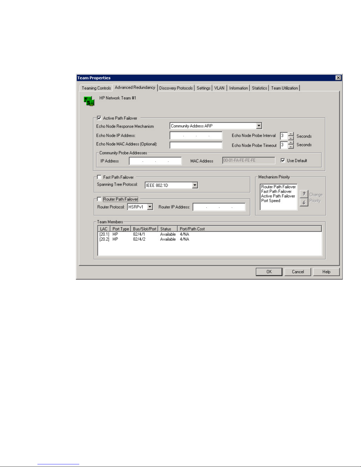
To configure Active Path Failover for a team:
1. On the NCU Main page, highlight the team.
2. Click Properties. The Team Properties page appears, with the Teaming Controls tab active.
3. Select the Advanced Redundancy tab.
Figure 3-3 Advanced Redundancy tab
4. Select the Active Path Failover option to enable it. Active Path Failover allows a team member
to send a packet to a remote node (called the echo node) and receive a reply to determine
that the team member sending the packet has a path to the node. The absence of a reply
within the specified time period can be used to determine when a team member does not
have a path to the echo node. The default setting is disabled. If Active Path Failover is
enabled, you must enter a valid IP address for the echo node. Entering an Echo Node MAC
address is optional.
5. Click the Echo Node Response Mechanism list and select the type of echo node request
probe to be sent.
• Community Address ARP — (Recommended) tests connectivity using a standard ARP.
This method works for all devices designated as the echo node including routers, HSRP
devices, and Linux servers. If Community Address ARP is selected, you must enter the
IP address to be used for the community probe. You can also configure the MAC address
to be used or use the MAC address default. The advantage of using Community Address
ARP is that it works on all echo node types.
• Directed ARP — tests connectivity with the echo node device using a modified ARP.
This method works for most switches or servers that are designated as the echo node.
It is not recommended for routers or Linux servers. The advantage of using Directed
ARP is that less configuration of parameters is required.
Advanced redundancy types 37
Page 38

6. In the Echo Node IP Address box type the IP address of the echo node.
7. Click the Echo Node Probe Interval list and select the interval at which packets are transferred
to the echo node. The default setting is 3 seconds.
8. (Optional) Type the MAC address of the echo node in the Echo Node MAC Address box.
Providing an echo node MAC address allows the echo node packets to be unicast to the echo
node. If no echo node MAC address is provided, the echo node packets are broadcast.
9. In the Echo Node Probe Timeout box, select the maximum time to wait for a response from
the echo node before considering the team member failed. The default setting is 3 seconds.
The timeout value must be less than or equal to the probe interval. If a larger value is entered
for the timeout, it is automatically set to the probe interval when you click OK.
10. If Community Address ARP is the echo node response mechanism, type the IP address to
be used in the Community Probe IP Address box. This must be a valid and unique IP address
on the same network as the team. All servers on the same network using this mechanism
can have the same Community Probe IP address. This box is not used for Directed ARP
probes.
11. Select the Use Default checkbox to use the default setting of 00-01-FA-FE-FE-FE or type the
MAC address in the Community Probe MAC Address box.
12. Click OK to save all changes and return to the NCU Main page. Or, click Cancel to ignore
all changes and return to the NCU Main page.
Fast Path Failover lets the server to determine the fastest path to the core network (or the
root bridge). With this failover method you can also select the type of Spanning Tree Protocol
used.
13. Click OK to apply the changes.
Configuring Fast Path Failover
Fast Path Failover is enabled through the Team Properties Advanced Redundancy tab. This
feature is disabled if a valid INP license is not installed on the system.
To configure Fast Path Failover for a team:
1. On the NCU Main page, highlight the team.
2. Click Properties. The Team Properties page appears, with the Teaming Controls tab active.
3. Select the Advanced Redundancy tab.
4. Select the Fast Path Failover option. This allows the server to determine the fastest path to
the core network (root bridge).
5. Click the Spanning Tree Protocol and select the type.
• IEEE 802.1D — IEEE 802.1D MAC Layer Bridges is VLAN unaware so it is not necessary
to configure Fast Path Failover to listen to VLAN.
• Cisco PVST+ — Cisco Per VLAN Spanning Tree Plus (Allows you to select the VLAN
ID to be used for Fast Path Failover monitoring.)
6. Click OK to save all changes and return to the NCU Main window. Or, click Cancel to ignore
all changes and return to the NCU Main page.
7. Click OK to apply the changes.
Configuring Router Path Failover
Router Path Failover is enabled through the Team Properties Advanced Redundancy tab. This
feature is disabled if a valid INP license is not installed on the system.
To configure Router Path Failover for a team:
1. On the NCU Main page, highlight the team.
2. Click Properties. The Team Properties page appears, with the Teaming Controls tab active.
3. Select the Advanced Redundancy tab.
38 Advanced Networking Features
Page 39

4. Select the Router Path Failover option. These Router Redundancy Protocols (HSRP, VRRP)
allow you to set up two or more routers into a single router group, which acts as a backup
for a virtual router.
5. Click the Router Protocol list and select the protocol type to monitor.
• HSRP — Cisco Hot Standby Router Protocol
• VRRP — Virtual Router Redundancy Protocol
6. Type the router IP address in the Router IP Address box to identify the address of the router
group (also known as the virtual router IP address).
7. Click OK to save all changes and return to the NCU Main page. Or, click Cancel to ignore
all changes and return to the NCU Main page.
8. Click OK to apply the changes.
Advanced Redundancy tab team members information
Team Members window includes the following information:
• LAC. Displays the local area connection.
• Port Type. Displays the NC model number.
• Bus/Slot/Port. The bus, slot, and port location of the team member. A port location of 1 is
not reported and is left blank.
NOTE: The Team Members Bus/Slot/Port category changes to Bus/IO Bay/Port for HP
Blade servers, like the BL860c.
• Status. Displays team member status: Refer to "Configuring a Dual Channel Load Balancing
team".
• Router Path State. If Router Path is enabled, it displays the state: OK, Degraded, Failed, and
Failed (Split LAN); otherwise, the column is not displayed.
• Fast Path State. If Fast Path is enabled, it displays the state: OK, Degraded, Failed, and Failed
(Split LAN); otherwise, the column is not displayed.
• Active Path State. If Active Path is enabled, it displays the state: OK, Degraded, and Failed;
otherwise, the column is not displayed.
• User Ranking. Displays the current user ranking of the port when Network Fault Tolerance
Only with Preference Order or Transmit Load Balancing with Fault Tolerance and Preference
Order is in use for the current team member; otherwise, the column is not displayed.
• Port/Path Cost. Displays the port/path cost for the port or "disconnected" if the adapter does
not have a link.
Configuring VLAN IDs
If Active Path Failover, Fast Path Failover (with Cisco PVST+ set as the Spanning Tree Protocol),
or Router Path Failover are configured for a team, you can select the VLAN ID for validation
and monitoring.
Before creating and editing VLANs, you should be aware that:
• The NCU supports IEEE 802.1Q VLAN tagging only.
• The NCU supports a VLAN identifier range of 1 to 4094.
• Up to 64 VLANs can be defined for a team.
To create a VLAN for a team:
1. From the NCU Main page, highlight the team.
2. Click VLAN (802.1Q). The VLAN tab appears.
Advanced redundancy types 39
Page 40
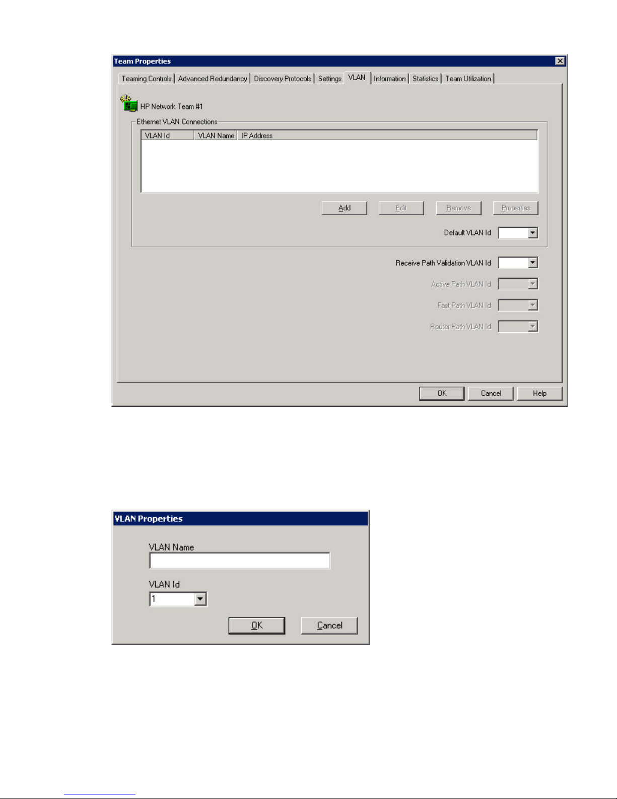
Figure 3-4 VLAN tab
The VLAN tab shows all VLANs that currently exist for the team. The list includes both
existing VLANs and new VLANs that have been created but that have not yet been applied.
Newly created VLANs are applied using the OK button on the Main page.
3. To create a new VLAN, click Add. The VLAN Properties input box appears.
Figure 3-5 VLAN Properties input box
4. Enter a user-defined VLAN name. Every VLAN must have a name assigned to it. Duplicate
names are allowed if you want to use the same names for different VLAN IDs.
5. The next available VLAN ID appears in the VLAN ID box. Change the VLAN ID by either
typing an ID or by using the list to select a valid ID. A valid ID is any number that is not
already being used for a VLAN defined on this team or adapter and that is in the range of
1-4094.
40 Advanced Networking Features
Page 41

6. Click OK. The new VLAN is saved and the VLAN tab appears. The new VLAN you created
appears in the list on the VLAN tab.
7. Select from the following:
• Default VLAN Id: displays the VLAN ID to which all packets received without a VLAN
tag are sent. The default is the lowest VLAN ID defined for the team.
• Receive Path Validation VLAN Id: allows you to select the VLAN on which Receive
Path Validation Heartbeat Frames are transmitted. This control is enabled only when
Receive Path Validation Heartbeats are enabled on the Team Settings tab. The default
setting is the VLAN on the team with the lowest VLAN ID at the time the team is created.
• Active Path VLAN Id: allows you to select the VLAN ID used for Active Path Failover
validation. This control is enabled only if Active Path Failover is configured for the
team. The default setting is the VLAN on the team with the lowest VLAN ID at the time
the team is created.
• Fast Path VLAN Id: allows you to select the VLAN ID used for Fast Path Failover
monitoring. This control is enabled only if Fast Path Failover is configured for the team
and Cisco PVST+ is set as the Spanning Tree Protocol. The default setting is the VLAN
on the team with the lowest VLAN ID at the time the team is created.
• Router Path VLAN Id: allows you to select the VLAN ID used for Router Path Failover
monitoring. This control is enabled only if Router Path Failover is configured for the
team. Router Path Failover is not available for the following team type: Switch-assisted
Load Balancing with Fault Tolerance (SLB), and 802.3ad Dynamic with Fault Tolerance.
8. Make any VLAN and VLAN ID changes then click OK. The new settings are saved. The
NCU Main page appears. You must also click OK on the Main page to apply the changes.
Advanced redundancy types 41
Page 42

42
Page 43

4 Using discovery protocols
This chapter describes how to configure and monitor the discovery protocols enabled by an
Integrity Essentials Intelligent Networking Pack license.
About Cisco Discovery Protocol and Link Layer Discovery Protocol
CDP and LLDP are layer two, neighbor device discovery protocols that run on all networking
devices such as routers, access servers, bridges, and switches. Using CDP or LLDP, a device can
advertise its existence to other devices and also receive information about neighboring devices
on the same LAN or on the remote side of a WAN.
CDP and LLDP are media and protocol independent protocols that allow two systems to learn
about each other even if they use different network layer protocols. CDP and LLDP obtain
protocol addresses of neighboring devices and discover the platform of those devices including
information about the interfaces a router uses. The HP NCU supports CDP Version 1, CDP
Version 2, and LLDP.
The following information is provided by CDP Version 1, CDP Version 2 and LLDP:
• Protocol Type
• Device name
• Port ID
• Platform name of the device
• Type of device
The following information is provided only with CDP Version 2 and LLDP:
• VTP management domain name
• Native Vlan ID for untagged packets on the interface
• Duplex
Each team member configured for CDP or LLDP registers an address at which it can receive
CDP or LLDP messages. The advertisements that come from network devices such as the switch
will contain this information.
A network administrator can use the information from CDP or LLDP to build a basic picture of
their network, which can be used to detect misconfigurations and troubleshooting problems on
the network.
Configuring discovery protocols
From the Discovery Protocols tab, you can configure CDP and LLDP settings for the selected
team. These advanced teaming features are disabled unless a valid Integrity Essentials Intelligent
Networking Pack license is installed on the system. For more information on how to install a
license, refer to Chapter 1.
To access the Discovery Protocols tab for a team:
1. On the NCU main window, select a team.
2. Click Properties to display the Team Properties window.
3. Select the Discovery Protocols tab to display the Team Discovery Protocols tab.
About Cisco Discovery Protocol and Link Layer Discovery Protocol 43
Page 44
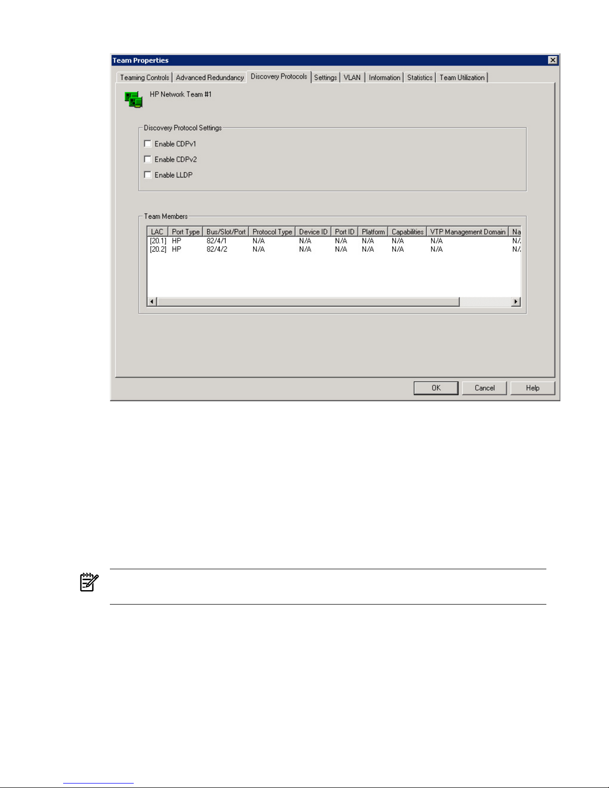
Figure 4-1 Team Discovery Protocols tab
4. In the Discovery Protocol Settings group select Enable CDPv1, Enable CDPv2, or Enable
LLDP to set the CDP version or LLDP for which to listen.
5. Click OK to accept the settings and return to the NCU main window.
6. Click OK on the NCU main window to apply the settings.
Team Members are listed in order by Group ID and then by Team Member ID. Information about
team members includes:
• LAC — The name of the local area connection.
• Port Type — NC model number of the port.
• Bus/Slot/Port — The bus, slot, and port location of the team member. A port location of 1
is not reported and is left blank.
NOTE: The Team Members Bus/Slot/Port category changes to Bus/IO Bay/Port for HP
Blade servers, like the BL860c.
• Protocol Type — CDPv1, CDPv2, or LLDP
• Device ID — The device name.
• Port ID — The port on which the CDP or LLDP packet is sent.
• Platform — The hardware platform name of the device.
• Capabilities — The type of device. Device types include:
— Unknown
— Router
— Transparent bridge
— Source-routing bridge
44 Using discovery protocols
Page 45

— Switch
— Host
— IGMP (Internet Group Management Protocol) Device
— Repeater
• VTP Management Domain — The system's VTP management domain name. This is used
to verify VTP domain configuration in adjacent network nodes.
• Native VLAN ID — The VLAN for untagged packets on the interface. CDP or LLDP learns
the native VLAN for an interface. This is implemented only for interfaces that support the
IEEE 8021Q protocol.
• Duplex — Current duplex mode of the team member: Unknown, Half, or Full.
The following controls are available:
• OK — Closes the window and returns you to the Main window.
• Cancel — Closes the window and returns you to the Main window.
• Help — Launches the context-sensitive NCU Help file.
Configuring discovery protocols 45
Page 46

46
Page 47

5 IGMP support
Internet Group Management Protocol (IGMP) is used to register dynamic multicast group
membership. It can register a router to receive specific multicast traffic. IGMP traffic is only be
sent to those team members that are part of a multicast group.
When a server runs an application that wants to join a multicast group, the join message is sent
out to the aggregation and only those ports in the multicast group. During a failover situation,
the NCU maintains connectivity with the multicast group and responds with IGMP reports.
The HP NCU supports IGMP in this release, but this support does not require any user input in
the NCU; therefore, no windows or controls exist for it.
47
Page 48

48
Page 49

6 Troubleshooting
This section provides possible solutions to problems that may occur during the configuration of
Intelligent Networking Pack features. The following tables provide steps you should take before
calling your service representative.
• Installing an Intelligent Networking Pack license: contains troubleshooting information
about installing an Intelligent Networking Pack license.
• Using Virus Throttle: contains troubleshooting information about using Virus Throttle.
• Configuring advanced networking features: contains troubleshooting information about
configuring advanced networking features.
• Configuring discovery protocols: contains troubleshooting information about configuring
discovery protocols.
Installing an Intelligent Networking Pack license
Table 6-1 Installing an Intelligent Networking Pack license
Possible SolutionPossible CauseProblem
N/AThis is correct behavior of Integrity
Essentials licensing.
Once installed on the system, the
license is “attached” to the server and
cannot be revoked. The license stays
with that server for the life of the
server. The license is attached to the
server serial number, so a change in
server name or IP address will not
jeopardize the license.
The Intelligent Networking Pack
license is installed but I cannot
uninstall it.
Using Virus Throttle
Table 6-2 Using Virus Throttle
Possible SolutionPossible CauseProblem
In a time-sensitive manner, identify the
program or programs responsible for the
“virus-like” behavior.
• If the program or programs are
unknown, treat as a virus.
• If the program or programs are
known, reconfigure the Virus Throttle
Configuration parameters to not
trigger on such normal or expected
activity.
A virus has infected your server, OR:
A non-virus program is exhibiting
“virus-like” behavior by making
more connections to more unknown
hosts than the Virus Throttle
Configuration parameter settings are
set for.
The Virus Throttle Status and
Configuration utility Status tab
indicates that “virus-like” activity
is occurring.
Installing an Intelligent Networking Pack license 49
Page 50

Configuring advanced networking features
Table 6-3 Configuring advanced networking features
Possible SolutionPossible CauseProblem
Verify the echo node device is on the
same IP subnet as the team.
• If echo node device is not on the same
IP subnet, reconfigure the echo node
settings on the Advanced Redundancy
tab for the team to a device that is on
the same IP subnet. Retest with these
settings.
• If the echo node device is on the same
IP subnet, can you ping the echo
node? If No, check the echo node
device to ensure it is operating and
the IP information is correct.
• If using VLANs, ensure the correct
VLAN is chosen for the Active Path
VLAN ID on the VLAN Tab of the
team.
Active Path Failure is a failure
condition of the Active Path Failover
mechanism. If all members of the
team have a yellow X with a status of
“Active Path Failure,” this means
none of the members were able to
reach the echo node device.
All members of the team currently
have a yellow X with a status of
“Active Path Failure” and the team
is degraded (yellow team icon).
Open the Network Configuration Utility
(NCU) and go to the Advanced
Redundancy tab for the team. Check the
Mechanism Priority setting.
If Active Path Failover is used in this
team type, it must have a higher
Mechanism Priority than the Preference
Order.
Reconfigure the settings so Active Path
Failover is above Preference Order in the
Mechanism Priority list box.
This may be expected behavior based
on the configured settings.
An NFT Preference Order Only
with Active Path Failover-enabled
team prefers a team member with
a yellow X over a member without
a yellow X.
The Network Configuration Utility
(NCU) does not show any failures
on the team; however I cannot
reach (ping) the echo node.
Open the Network Configuration Utility
(NCU) and go to the Advanced
Redundancy tab for the team. Check the
Mechanism Priority setting.
If Fast Path Failover is to be used in this
team type, it must have a higher
Mechanism Priority than the Preference
Order.
Reconfigure the settings so Fast Path
Failover is above Preference Order in the
Mechanism Priority list box.
This may be expected behavior based
on the configured settings.
An NFT Preference Order Only
with Fast Path Failover team
prefers a team member with a
yellow X over a member without
a yellow X.
The Network Configuration Utility
(NCU) does not show any failures
on the team; however the team
member with the highest path cost
is the Primary adapter instead of
the member with the lower cost.
Open the Network Configuration Utility
(NCU) and go to the Information tab for
the team. Check the Current Mode.
If the current mode is 802.3ad Dynamic
with Fault Tolerance, this is normal
behavior to ignore the echo node
mechanism. This mechanism is only
applicable if the automatic team type
ends up in TLB (Transmit Load
Balancing) mode.
This may be expected behavior based
on the configured settings.
The Automatic team type with
Active Path Failover enabled team
does not detect an Echo Node
failure.
50 Troubleshooting
Page 51

Table 6-3 Configuring advanced networking features (continued)
Possible SolutionPossible CauseProblem
Open the Network Configuration Utility
(NCU) and check to see if the team
contains a 10/100 network adapter
(NC31xx series).
If so, remove the NC31xx series and
apply changes before attempting to
enable Active Path Failover. The NC31xx
10/100 adapters do not support the Active
Path Failover mechanism.
This may be expected behavior based
on the configured settings.
The Intelligent Networking Pack
license is installed but I cannot
enable Active Path Failover on the
team. It is grayed out.
Open the Network Configuration Utility
(NCU) and go to the Information tab for
the team. Check the Current Mode.
If the current team mode is 802.3ad
Dynamic with Fault Tolerance or SLB
(Switch-assisted Load Balancing, this is
normal behavior. These team modes do
not support Fast Path Failover.
This may be expected behavior based
on the configured settings.
The Intelligent Networking Pack
license is installed but I cannot
enable Fast Path Failover on the
team. It is grayed out.
First, ensure that there are no split LAN
conditions possibly caused by an
upstream link failure to the core network.
Second, if there are no split LAN
conditions, go to the Advanced
Redundancy tab for the team. Set the
timers under Active Path Failover to a
greater value. Possibly the timers are set
too low for the network environment.
Try doubling the current timers and
retest with these settings.
Active Path Failure is a failure
condition of the Active Path Failover
mechanism. If one or more members
(but not all) of the team have a red X
with a status of “Active Path Failure,”
this means those members did not
receive a response from the Echo
Node device during the last interval.
One or more members (but not all)
of the team currently have a red X
with a status of “Active Path
Failure” and the team is degraded
(yellow team icon).
Change the Active Path Mechanism to
Community Address ARP. This newer
method works with all devices as the
Echo Node. It requires an additional IP
address for the Community ARP;
however all servers on the network using
this feature can use this address.
If using the Directed ARP method
and the Echo Node device is a router
or a Linux server, this is expected
behavior.
The Active Path Mechanism is
enabled and all adapters in the
team show a yellow X with a status
of “Active Path Failure,” however
I can successfully ping the Echo
Node device.
Ensure the Spanning Tree Protocol is
running on the switches in the network.
Ensure the protocol selected on the
Advanced Redundancy Tab is the same
protocol running on the switches in the
network. Only PVST+ and 802.1D are
supported.
The Spanning Tree Protocol may be
disabled on the switches or the wrong
protocol may be selected on the
Advanced Redundancy Tab of the
team.
All members in the team show a
yellow X with a status of “Fast Path
Failure,” however the adapters are
operating successfully.
Ensure the Native VLAN of the switch
is the same as the Default/Native VLAN
configured in the NCU on the VLAN Tab
of the team.
For example if the Native VLAN on the
ports you are connected to is VLAN 20,
then ensure the VLAN Tab of the team
is configured for VLAN 20 on the
Default//Native VLAN box.
The Native VLAN of the switch may
not match what is configured on the
VLAN Tab of the team in the
Default/Native VLAN box.
When using the Fast Path
mechanism with VLANS and
PVST+, my adapters all show a
yellow X with a status of “Fast Path
Failure,” however the adapters are
operating successfully.
Configuring advanced networking features 51
Page 52

Table 6-3 Configuring advanced networking features (continued)
Possible SolutionPossible CauseProblem
Ensure the Router Protocol setting is
configured for the correct protocol and
verify the Router IP Address entry.
The router protocol type or the router
IP address may be set wrong.
When using the Router Path
mechanism, all members in a team
show a yellow X with a status of
"Degraded (Router Path)";
however, all adapters are operating
successfully.
Ensure that the Default VLAN ID and
Router Path VLAN ID are the same in
the NCU.
The Default/Native VLAN ID and the
Router Path VLAN ID do not match
when the ports on the switch have
not been tagged to any VLAN.
When using the Router Path
mechanism, all members in a team
show a yellow X with a status of
"Degraded (Router Path)";
however, all adapters are operating
successfully.
Go to Advanced Redundancy Tab and
enable the failover mechanism such as
Active Path Failover or Fast Path Failover
or Router Path Failover for which you
are unable to set VLAN ID.
Open the NCU and go to the Information
tab for the team. Check the Current
Mode. If the current team mode is
802.3ad Dynamic with Fault Tolerance
or SLB (Switch-assisted Load Balancing),
this is normal behavior. These team
modes do not support Fast Path Failover,
Active Path Failover and Router Path
Failover.
If you are unable to set the VLAN ID for
fast path even though Fast Path has been
selected in the Advanced Redundancy
tab, then consider changing the Spanning
Tree Protocol as Cisco PVST+.
This may be expected behavior based
on the configured settings.
Unable to select VLAN ID for
Active Path, Fast Path, and Router
Path.
Configuring discovery protocols
Table 6-4 Configuring discovery protocols
Possible SolutionPossible CauseProblem
If this information is important to you,
consider using CDPv2 instead.
This is expected behavior when using
CDPv1. This feature is only available
with CDPv2.
When using CDPv1, the
information tab does not display
the VTP management domain
name for my devices.
Install an Integrity Essentials Intelligent
Networking Pack license key.
This is expected behavior for
licensable features.
The Discovery Protocol Settings
group is disabled and I can't set the
CDP or LLDP.
52 Troubleshooting
Page 53

Table 6-4 Configuring discovery protocols (continued)
Possible SolutionPossible CauseProblem
Disable CDP or LLDP then re-enable it
and verify that the team registers the
address.
When CDP or LLDP is first enabled,
it may take 30 seconds to receive the
first CDP or LLDP frame. It is
possible that this delay occurred as
the teaming driver attempted to
register the CDP or LLDP multicast
address with the miniport. This delay
may have caused the team to fail to
register the multicast address.
CDP or LLDP is enabled and CDP
or LLDP frames are being
transmitted by the network device
but they are not being received by
the team.
Map your network configuration using
Discovery Protocol and verify the
configuration is satisfactory.
Some network devices may only
transmit a CDP or LLDP frame down
a single port in a trunk. In that case,
you should expect that the data from
the port that is receiving the frame
should represent all ports in that
aggregation.
If two ports in an aggregation happen
to contain different data (like
different Device IDs) that may alert
you to a network misconfiguration.
When using SLB, 802.3ad, and
Dual-Channel teams some ports in
my aggregation (trunk) do not
have any information displayed.
Configuring discovery protocols 53
 Loading...