

Page 1

HP Insight Control Environment Suites
User Guide
HP Part Number: 411803-401
Published: April 2009, Tenth Edition
Page 2

© Copyright 2009 Hewlett-Packard Development Company, L.P.
Legal Notices
Confidential computer software. Valid license from HP required for possession, use or copying. Consistent with FAR 12.211 and 12.212, Commercial
Computer Software, Computer Software Documentation, and Technical Data for Commercial Items are licensed to the U.S. Government under
vendor's standard commercial license.
The information contained herein is subject to change without notice. The only warranties for HP products and services are set forth in the express
warranty statements accompanying such products and services. Nothing herein should be construed as constituting an additional warranty. HP shall
not be liable for technical or editorial errors or omissions contained herein.
Acknowledgments
Microsoft, Windows, Windows NT, Windows Server, and Windows XP are U.S. registered trademarks of Microsoft Corporation. VMware, VMware
Server, GSX Server, ESX Server, and VMotion are trademarks of VMware, Inc. Adobe and Acrobat are trademarks of Adobe Systems Incorporated.
AMD is a trademark of Advanced Micro Devices, Inc. Intel, Pentium, and Xeon are trademarks of Intel Corporation in the U.S. and other countries.
UNIX is a registered trademark of The Open Group. Java is a US trademark of Sun Microsystems, Inc. Oracle is a registered trademark of Oracle
Corporation and/or its affiliates.
Page 3

Table of Contents
About this document....................................................................................15
Intended audience................................................................................................................................15
Related documents................................................................................................................................15
1 Introduction.............................................................................................17
Overview.............................................................................................................................................17
HP Insight Control Environment Suites .....................................................................................................17
HP Systems Insight Manager.............................................................................................................17
HP Insight Control Environment Suites (ProLiant ML, ProLiant DL, and ProLiant BladeSystem servers and blade
workstations)...................................................................................................................................17
HP Insight Control Environment for BladeSystem ..................................................................................18
Key benefits for HP Insight Control Environment Suites ...............................................................................18
Licensing..............................................................................................................................................19
Platform support....................................................................................................................................19
Component summary.............................................................................................................................19
2 Licensing HP Insight Control Environment Suites ...........................................23
Preparing for HP Insight Control Environment licensing...............................................................................23
Adding and applying licenses to Insight Control Environment......................................................................23
Adding and applying licenses to HP Insight Control Environment for BladeSystem uses three license keys:.........24
Licensing HP Insight Rapid Deployment Software.......................................................................................25
License types...................................................................................................................................25
Applying a license file during a first-time installation or upgrade............................................................25
Adding a license file to an existing installation.....................................................................................25
Replacing licenses in an existing installation........................................................................................25
Adding iLO 2 Advanced license keys.......................................................................................................25
3 Managing server blades from HP SIM.........................................................27
Overview.............................................................................................................................................27
What's New in HP BladeSystem Integrated Manager 3.5 with Update 1................................................27
Racks and enclosures.............................................................................................................................27
Overview........................................................................................................................................27
Rack and enclosure collections...........................................................................................................27
System page........................................................................................................................................28
Viewing racks.......................................................................................................................................28
Navigating the System(s) tab..................................................................................................................29
System List buttons............................................................................................................................31
Save a collection.............................................................................................................................32
Deleting a Blade system....................................................................................................................32
Navigating the Event tab........................................................................................................................32
Filter Criteria...................................................................................................................................33
Event Status Legend..........................................................................................................................33
Event Details...................................................................................................................................33
Event Collection Columns..................................................................................................................33
Selection...................................................................................................................................34
State.........................................................................................................................................34
Severity.....................................................................................................................................34
Event Type.................................................................................................................................34
System Name.............................................................................................................................34
Event Time.................................................................................................................................34
Assigned To...............................................................................................................................34
Comments.................................................................................................................................34
Table of Contents 3
Page 4

System Type...............................................................................................................................34
Rack Name...............................................................................................................................34
Enclosure Name.........................................................................................................................35
Event Management Buttons...............................................................................................................35
Viewing enclosures................................................................................................................................35
Viewing an enclosure.......................................................................................................................38
Creating a rack...............................................................................................................................39
Editing a rack..................................................................................................................................40
Saving an Onboard Administrator configuration..................................................................................41
Restoring an Onboard Administrator configuration...............................................................................41
Deleting a configuration script...........................................................................................................41
4 Monitoring and controlling servers..............................................................43
Configuring Insight Power Manager options.............................................................................................43
Using the iLO browser interface..............................................................................................................44
Using the System Status tab...............................................................................................................44
Using the Remote Console tab...........................................................................................................45
Using the Virtual Devices tab.............................................................................................................46
Monitoring PMP parameters...................................................................................................................46
Default PMP settings..............................................................................................................................46
Sample rate....................................................................................................................................46
Number of samples..........................................................................................................................46
Using the PMP interface.........................................................................................................................46
Online and Offline Analysis...................................................................................................................47
Systems detail frame.........................................................................................................................47
Server Tree frame.............................................................................................................................47
Results frame...................................................................................................................................48
Storage Analysis...................................................................................................................................48
PMP Reports.........................................................................................................................................48
Offline Analysis....................................................................................................................................49
Manual Log Purge.................................................................................................................................50
Using PMP...........................................................................................................................................51
Opening the HP SIM console............................................................................................................51
Debugging a server bottleneck condition............................................................................................51
Selecting the server.....................................................................................................................52
Displaying the memory status.......................................................................................................52
Displaying the memory graph......................................................................................................53
Contrasting the graphical display............................................................................................................53
Expanding the local storage..............................................................................................................53
Displaying the controller...................................................................................................................54
Displaying the port...........................................................................................................................54
Displaying the drive.........................................................................................................................55
Displaying the inventory....................................................................................................................55
Debugging a network storage bottleneck condition..............................................................................56
Selecting the server.....................................................................................................................56
Displaying the storage status........................................................................................................57
Displaying the logical drive under network storage..........................................................................57
Displaying the array....................................................................................................................57
Debugging a virtual machine host and guest bottleneck condition..........................................................57
Selecting the server (virtual machine host) .....................................................................................58
Displaying the virtual machine host status.......................................................................................58
Displaying the virtual machine guests page....................................................................................59
Displaying the virtual machine guest.............................................................................................59
Displaying the virtual machine guest performance...........................................................................59
Addressing performance issues with no hardware upgrade recommendation...........................................60
Performing a static analysis...............................................................................................................60
General usage...........................................................................................................................60
Half duplex port.........................................................................................................................61
4 Table of Contents
Page 5

Unassigned disks........................................................................................................................61
Reduced SCSI speed...................................................................................................................62
Host bus balancing.....................................................................................................................62
Performing Online Analysis...............................................................................................................62
Performing Offline Analysis...............................................................................................................63
Data reporting.................................................................................................................................64
Generating a Static Analysis Report..............................................................................................65
Generating a SQL queries list..................................................................................................65
Generating a System Summary Report...........................................................................................65
Generating a SQL queries list..................................................................................................66
Generating a CSV File Generator Report.......................................................................................66
Generating a SQL queries list..................................................................................................66
Generating a Server Availability Report.........................................................................................67
Generating a SQL queries list..................................................................................................67
Licensing Integrity and Storage Systems..............................................................................................67
Licensing virtual machine hosts and virtual machine guests....................................................................67
Monitoring administration.................................................................................................................68
Changing server monitoring status................................................................................................68
Enabling virtual machine host and virtual machine guests logging..........................................................69
Monitoring parameters................................................................................................................70
Number of samples....................................................................................................................71
Performance threshold setting.......................................................................................................71
Modifying the sample rate...........................................................................................................71
Modifying log days.....................................................................................................................71
Modifying Management Agents from the Control Panel..............................................................71
Modifying Management Agents from Internet Explorer...............................................................72
Setting performance thresholds..........................................................................................................72
Threshold values.........................................................................................................................74
Manual Log Purge.................................................................................................................................74
5 Deploying and securing servers..................................................................75
Configuring BladeSystem servers and image installs using the HP Insight Rapid Deployment software...............75
Configuring scripted installs ..............................................................................................................75
Configuring SAN-attached scripted install ..........................................................................................75
Configuring image installs.................................................................................................................75
Configuring HP BladeSystem enclosures .............................................................................................76
Using HP Insight Rapid Deployment software............................................................................................76
Deployment Console basics...............................................................................................................76
Connecting server blades..................................................................................................................77
Deploying the first server blade..........................................................................................................78
Reconfiguring the server blade..........................................................................................................78
Vulnerability scanning and deploying patches and fixes.............................................................................78
HP Vulnerability and Patch Management Pack (VPM) overview...............................................................78
Provided scan definitions..................................................................................................................79
Scanning for vulnerabilities...............................................................................................................79
Viewing, modifying, or canceling a scheduled task.........................................................................80
Viewing vulnerability scan results..................................................................................................80
Vulnerability scan results guidelines.........................................................................................80
Viewing vulnerability scan results by scan name........................................................................80
Viewing vulnerability scan results by scan system.......................................................................80
Customizing vulnerability scan definitions......................................................................................81
Deleting scan results...................................................................................................................81
Deleting scan results by scan name..........................................................................................81
Deleting scan results by system................................................................................................81
Deploying patches and fixes..............................................................................................................81
Deploying patches and fixes based on a vulnerability scan..............................................................81
Deploying patches without a vulnerability scan...............................................................................83
Viewing the patch repository........................................................................................................84
Table of Contents 5
Page 6

Viewing patch reboot status.........................................................................................................84
Validating installed patches...............................................................................................................86
Removing patches............................................................................................................................86
Redeploying the VPM Patch Agent......................................................................................................88
HP Vulnerability and Patch Management Pack events............................................................................89
6 Using HP Virtual Machine Management Pack...............................................91
Virtual Machine Management Pack interface overview...............................................................................91
Virtual machine host..............................................................................................................................91
Virtual machine guest............................................................................................................................93
Configured and unconfigured virtual machine hosts...................................................................................94
Configured.....................................................................................................................................95
Unconfigured..................................................................................................................................95
Task execution process...........................................................................................................................95
Using Virtual Machine Management Pack controls and tools.......................................................................95
Starting or resuming a virtual machine guest (Windows or Linux)...........................................................96
Shutting down or stopping a virtual machine guest (Windows or Linux)...................................................97
Suspending a virtual machine guest...................................................................................................97
Resetting or restarting a virtual machine guest......................................................................................98
Copying a virtual machine guest (Windows or Linux)............................................................................98
SUSE Linux scenario....................................................................................................................99
Moving a virtual machine guest (Windows or Linux).............................................................................99
Creating a virtual machine guest template.........................................................................................101
Deploying a virtual machine guest template.......................................................................................102
Creating a virtual machine guest backup..........................................................................................102
Restoring a virtual machine guest backup..........................................................................................103
Restoring the most recent virtual machine guest backup.......................................................................104
Recovering virtual machines of a failed host on a VMware ESX Server or HP integrated Citrix XenServer....104
Setting an alternate virtual machine host on a VMware ESX Server or HP integrated Citrix XenServer........104
Removing an alternate virtual machine host on a VMware ESX Server or HP integrated Citrix XenServer....105
Launching VNC.............................................................................................................................105
Restarting the VMM Agent..............................................................................................................105
Setting or removing the performance threshold..................................................................................105
Registering virtual machine hosts......................................................................................................106
Registering virtual machine hosts using the command line interface......................................................106
Registering virtual machine hosts for Linux CMS.................................................................................106
Launching remote access................................................................................................................107
Launching Remote Console..............................................................................................................107
For VMware ESX Server 2.5.x ...................................................................................................108
For VMware Server...................................................................................................................108
Launching Remote Desktop..............................................................................................................108
Updating the HP SIM certificate on the Virtual Machine Management Service.......................................108
Unregistering virtual machine hosts..................................................................................................108
Configuring the xapi port for HP integrated Citrix XenServer.....................................................................108
Configuring WMI Mapper proxy server settings for Hyper-V.....................................................................109
Configuring the polling frequency for virtual machine status checks............................................................109
Handling prefailure events....................................................................................................................109
Handling automatic prefailure events................................................................................................109
Prerequisites..................................................................................................................................110
Handling automatic prefailure events using the VirtualCenter DRS cluster enabled in the VirtualCenter
Server..........................................................................................................................................110
Handling semi-automatic prefailure events with the VirtualCenter DRS cluster enabled in the VirtualCenter
server...........................................................................................................................................110
Handling automatic prefailure events using the Set Alternate host feature...............................................111
Handling semi-automatic events using the Set Alternate host feature......................................................111
Handling automatic prefailure events using Citrix XenServer resource pool with HA enabled....................111
Handling automatic prefailure events using Citrix XenServer resource pool with HA disabled...................112
Prefailure event list.........................................................................................................................112
6 Table of Contents
Page 7

ProLiant system and environmental events.....................................................................................112
ProLiant storage events..............................................................................................................112
Failed host recovery............................................................................................................................114
Setting up the recovery feature..............................................................................................................114
Creating a CriticalVmHost collection.....................................................................................................115
Setting the alternate virtual machine host................................................................................................115
Scheduling the recovery of virtual machines of failed hosts.......................................................................115
Launching SCVMM.............................................................................................................................117
Microsoft Virtual Server Host System page.........................................................................................117
Microsoft Virtual Server Guest System page.......................................................................................118
Launching VC.....................................................................................................................................118
VMware ESX Server Host System page.............................................................................................118
VMware ESX Server Guest System page...........................................................................................118
VirtualCenter information.....................................................................................................................119
Configuring Virtual Machine Management Pack on a Microsoft Cluster Server............................................120
Configuring Virtual Machine Management Pack on an HP integrated Citrix XenServer resource pool..............120
Considerations on VMM-enabled and HA-enabled resource pool:........................................................120
Configuring Virtual Machine Management Pack for Hyper-V hosts Microsoft failover cluster......................120
Multisystem aware tools available.........................................................................................................121
Performance information......................................................................................................................121
Displaying virtual machine host performance information.........................................................................121
Virtual machine host performance....................................................................................................121
Virtual machine performance...........................................................................................................122
Displaying virtual machine guest performance........................................................................................123
Virtual machine performance...........................................................................................................123
Resource allocation.............................................................................................................................123
Performance color codes......................................................................................................................124
Virtual Machine Management Pack infrastructure.....................................................................................124
7 Reporting..............................................................................................125
Reporting in HP SIM............................................................................................................................125
Software inventory details...............................................................................................................126
Printing reports..............................................................................................................................126
Sample PMP CSV file...........................................................................................................................126
PMP measurement categories................................................................................................................127
Servers.........................................................................................................................................127
Servers with MSVS or VMware GSX (VM Host) .................................................................................127
Servers with VMware ESX (VM Host) ...............................................................................................128
VM guest......................................................................................................................................128
Smart Array controllers...................................................................................................................128
Smart Array logical drives...............................................................................................................129
Smart Array physical arrays............................................................................................................129
SCSI buses attached to Smart Array controllers..................................................................................129
Fibre Channel host bus adapters......................................................................................................129
Fibre Channel enclosures................................................................................................................129
SCSI adapters...............................................................................................................................130
SCSI buses attached to SCSI adapters..............................................................................................130
SCSI drives attached to SCSI adapters..............................................................................................130
IDE controllers...............................................................................................................................130
Network adapters..........................................................................................................................130
Host buses....................................................................................................................................131
Sample PMP system summary report......................................................................................................131
System summary report for a server or MSVS/VMware GSX Host.........................................................131
System summary report for a VMware ESX Host ................................................................................132
System summary report for a VM Guest............................................................................................133
Overall PMP performance....................................................................................................................134
Sample PMP Static Analysis report........................................................................................................135
Sample PMP Server Availability report...................................................................................................135
Table of Contents 7
Page 8

Viewing patch installation status............................................................................................................135
Viewing patch installation status by patch.........................................................................................136
Viewing patch installation status by search filter.................................................................................136
Viewing patch installation status by system........................................................................................136
8 Troubleshooting......................................................................................137
General troubleshooting.......................................................................................................................137
General installation issues...............................................................................................................137
ASP.NET 1.1 installation error..........................................................................................................139
IIS error message appears during installation.....................................................................................139
Applying and assigning HP Insight Software suite licenses from HP SIM license manager .......................140
HP Insight Software licensing menus do not appear............................................................................140
Verifying environment functionality with Insight Software Advisor..........................................................140
HP Insight Software installation does not accept username, but password is already accepted by HP SIM...140
Updating passwords......................................................................................................................140
Uninstalling HP Insight Software.......................................................................................................141
Vulnerability and Patch Management Pack troubleshooting.......................................................................142
VPM installation and configuration...................................................................................................142
Viewing VPM installation logs.....................................................................................................142
VPM installation updates MDAC and MSDE ................................................................................142
An error occurs when installing MSDE files from a Remote Desktop session.......................................142
“STAT Scanner WSI Requires IWAM and IUSR” error occurs during VPM installation.........................142
Installation fails with “Product RMS not installed: Service RMS error. The specified service does not exist
as an installed service (0x424)” message ...................................................................................143
VPM installation fails.................................................................................................................143
Cannot modify VPM acquisition settings to acquire updates from a local repository...........................143
Required open ports..................................................................................................................143
Modifying firewall configuration settings......................................................................................144
Configuring a DNS server..........................................................................................................144
All target systems do not have the same administrator credentials....................................................145
Multiple VPM servers.................................................................................................................145
Administrator credentials have been changed...............................................................................145
Uninstalling Vulnerability and Patch Management..............................................................................145
Remaining VPM files.................................................................................................................146
Reinstalling VPM.......................................................................................................................146
Vulnerability scans.........................................................................................................................146
Vulnerability and Patch Management cannot access target systems..................................................146
Windows...........................................................................................................................147
Windows XP.......................................................................................................................147
Linux target systems..............................................................................................................147
Scan reports cannot be viewed...................................................................................................147
A scan was submitted but never started.......................................................................................147
Scan results are inaccurate because of overlapping tasks..........................................................147
Current patch information is not displayed in scan reports.........................................................148
Patches and configuration fixes........................................................................................................148
VPM Patch Agent installation fails...............................................................................................148
A patch acquisition was started, but no patches are seen...............................................................148
HTTP 300 errors received during patch acquisition........................................................................149
Patches appear in a scan report but are not successfully deployed..................................................149
Check for missing patches.........................................................................................................149
Validating VPM Patch Agent installation.......................................................................................149
Patch installation status reports are not current or do not match information that appears in scan
reports....................................................................................................................................149
Other tools report that a Windows system is patched, but Vulnerability and Patch Management reports
patches needed........................................................................................................................150
Patch source for vendor patches is Microsoft or Red Hat............................................................150
Multiple events listed in HP SIM for patch deployments.............................................................150
STAT Scanner update error listed in the HP SIM event log.........................................................150
8 Table of Contents
Page 9

Radia internal error listed in the HP SIM event log....................................................................150
“Abuse of Service” error occurs when attempting to acquire Red Hat patches..............................150
Validate Installed Patches event does not complete .......................................................................150
HP SIM integration.........................................................................................................................150
9 Technical support...................................................................................151
HP Software Technical Support and Update Service................................................................................151
HP Installation and Startup Service for BladeSystem Integrated Manager infrastructure.................................151
HP contact information.........................................................................................................................152
A HP Performance Management Pack measurement parameter matrix..............153
Static analysis.....................................................................................................................................153
ATA disk array....................................................................................................................................153
ATA Disk Array Status.....................................................................................................................153
ATA Disk Array Inventory................................................................................................................153
ATA disk............................................................................................................................................154
ATA Disk Status.............................................................................................................................154
ATA Disk Inventory.........................................................................................................................154
Drive array.........................................................................................................................................154
Drive Array Status..........................................................................................................................154
Drive Array Inventory......................................................................................................................154
External storage enclosure....................................................................................................................154
External Storage Enclosure Status.....................................................................................................155
External Storage Enclosure Inventory................................................................................................155
Fibre Channel host bus adapter............................................................................................................155
Fibre Channel Host Bus Adapter Status.............................................................................................155
Fibre Channel Host Bus Adapter Inventory.........................................................................................155
Host buses.........................................................................................................................................155
Host Buses Status...........................................................................................................................156
Host Buses Inventory.......................................................................................................................156
IDE channel........................................................................................................................................156
IDE Channel Status........................................................................................................................156
IDE Channel Inventory....................................................................................................................156
IDE controller......................................................................................................................................156
IDE Controller Status.......................................................................................................................156
IDE Controller Inventory..................................................................................................................156
Logical drive.......................................................................................................................................156
Logical Drive Status........................................................................................................................157
Logical Drive Inventory....................................................................................................................157
Memory.............................................................................................................................................157
Memory Status..............................................................................................................................157
Memory Inventory..........................................................................................................................158
Network adapter................................................................................................................................158
Network Adapter Status..................................................................................................................158
Network Adapter Inventory.............................................................................................................158
Network connections...........................................................................................................................158
Network Connections Status............................................................................................................158
Network Connection Inventory.........................................................................................................158
Network port......................................................................................................................................158
Network Port Status........................................................................................................................159
Network Port Inventory...................................................................................................................159
Network storage array.........................................................................................................................159
Network Storage Array Status.........................................................................................................159
Network Storage Array Inventory.....................................................................................................159
Network storage controller...................................................................................................................159
Network Storage Controller Status....................................................................................................160
Network Storage Controller Inventory...............................................................................................160
Network storage enclosure...................................................................................................................160
Table of Contents 9
Page 10

Network Storage Enclosure Status....................................................................................................160
Network Storage Enclosure Inventory................................................................................................160
Network storage logical drives..............................................................................................................160
Network Share Status.....................................................................................................................160
Network Share Inventory................................................................................................................161
PCI bus..............................................................................................................................................161
PCI Bus Status...............................................................................................................................161
PCI Bus Inventory...........................................................................................................................161
Processors..........................................................................................................................................161
Processors Status............................................................................................................................161
Processors Inventory.......................................................................................................................162
SCSI adapter......................................................................................................................................162
SCSI Adapter Status.......................................................................................................................162
SCSI Adapter InventoryController Configuration.................................................................................162
SCSI storage enclosure........................................................................................................................162
SCSI Storage Enclosure Status..........................................................................................................163
SCSI Storage Enclosure Inventory.....................................................................................................163
SCSI drive..........................................................................................................................................163
SCSI Drive Status...........................................................................................................................163
SCSI Drive Inventory.......................................................................................................................164
Server metrics.....................................................................................................................................164
Server status..................................................................................................................................164
Server inventory.............................................................................................................................164
Smart Array controller..........................................................................................................................164
Smart Array Controller Status...........................................................................................................165
Smart Array Controller Inventory......................................................................................................165
Smart Array SCSI drive........................................................................................................................165
Smart Array SCSI Drive Status..........................................................................................................165
Smart SCSI Drive Inventory..............................................................................................................165
SATA Drives........................................................................................................................................166
SATA Drive Status...........................................................................................................................166
SATA Drive Inventory......................................................................................................................166
SAS Drives.........................................................................................................................................166
SAS Drive Status............................................................................................................................166
SAS Drive Inventory........................................................................................................................167
Storage components............................................................................................................................167
Storage Status...............................................................................................................................167
Storage Inventory...........................................................................................................................167
B HP Vulnerability and Patch Management infrastructure requirements and
additional VPM functionality.......................................................................169
Infrastructure.......................................................................................................................................169
VPM hardware requirements............................................................................................................170
VPM software requirements.............................................................................................................170
VPM Acquisition Utility requirements (optional)........................................................................................171
Target systems...............................................................................................................................171
Provided scans..............................................................................................................................171
Updating VPM credentials using the Change VPM Credentials Utility.........................................................172
Backing up and restoring the Vulnerability and Patch Management ...........................................................172
Component backup........................................................................................................................173
Component restoration...................................................................................................................173
Reinstalling Vulnerability and Patch Management to a new host...........................................................173
Vulnerability and Patch Management events...........................................................................................173
Scan events...................................................................................................................................173
Patch and fix events........................................................................................................................174
Acquisition events..........................................................................................................................175
Miscellaneous events......................................................................................................................175
10 Table of Contents
Page 11

Index.......................................................................................................177
Table of Contents 11
Page 12

12
Page 13

List of Tables
1 Related documents..............................................................................................................................15
1-1 HP components licensed with HP Insight Control Environment suites.......................................................21
2-1 Licensing HP Insight Control Environment ...........................................................................................23
6-1 Icons and tasks...............................................................................................................................95
7-1 PMP overall performance summary..................................................................................................134
B-1 Hardware requirements..................................................................................................................170
B-2 Software requirements...................................................................................................................170
B-3 VPM Acquisition Utility requirements................................................................................................171
B-4 Provided scan definitions................................................................................................................172
B-5 VPM scan events...........................................................................................................................173
B-6 VPM patch and fix events...............................................................................................................174
B-7 VPM acquisition events..................................................................................................................175
B-8 Miscellaneous VPM events..............................................................................................................175
13
Page 14

14
Page 15

About this document
Intended audience
This document is for the person who installs, administers, and troubleshoots servers and storage systems. HP
assumes you are qualified in the servicing of computer equipment and trained in recognizing hazards in
products with hazardous energy levels.
Related documents
In addition to this guide, the following table lists the documentation resources available for each of the
components on the HP Insight Software DVDs. All HP Insight Control Environment Suites components are
located on #1.
The
HP Insight Control Environment Suites Support Matrix
lists supported target servers and operating
systems for the components in the various HP Insight Control Environment Suites suites.
For a comprehensive list of supported products in the release, see the latest support matrix at http://
www.hp.com/go/ice .
Table 1 Related documents
DocumentComponent
• HP Insight Control Environment website at http://www.hp.com/go/ice
•
HP Insight Control Environment Suites Release Notes
•
HP Insight Control Environment Suites Support Matrix
•
HP Insight Control Environment Suites User Guide
•
HP Insight Software Installation Checklist
•
HP Insight Software Installation and Configuration Guide
•
HP Insight Software Quick Setup Poster
• Use the Documentation tab from the Autorun screen on Insight Software DVD #1 for individual
documentation for each component.
HP Insight Control Environment
Suites
• HP Systems Insight Manager website at http://www.hp.com/go/hpsim
•
HP Systems Insight Manager Installation and Configuration Guide for HP-UX
•
HP Systems Insight Manager Installation and Configuration Guide for Linux
•
HP Systems Insight Manager Installation and Configuration Guide for Microsoft Windows
•
HP Systems Insight Manager User Guide
•
Quick Start Guide
HP Systems Insight Manager
• HP BladeSystem Integrated Manager in HP Systems Insight Manager website at http://
h18013.www1.hp.com/products/servers/management/bsme/index.html
• HP BladeSystem c-Class Firmware & Upgrades at http://www.hp.com/go/bladesystemupdates
HP BladeSystem Integrated
Manager
• HP Insight Power Manager website at http://www.hp.com/go/ipm
•
Insight Power Manager User Guide
•
Insight Power Manager Installation and Configuration Guide
•
Insight Power Manager Support Matrix
•
Insight Power Manager ReadMe
Insight Power Manager
• HP iLO 2 Advanced Pack and iLO 2 Advanced for BladeSystem website at http://www.hp.com/
go/ilo
•
User Guide
iLO2 Advanced Pack and iLO
2 Advanced for BladeSystem
• HP Insight Rapid Deployment software website at http://www.hp.com/go/rdp
•
HP Insight Rapid Deployment Software User Guide
• HP website at http://www.hp.com/servers/rdp/kb (Regularly updated troubleshooting
information, frequently asked questions, and specific how-to procedures are available on this
site.)
HP Insight Rapid Deployment
Software
Intended audience 15
Page 16

DocumentComponent
Documentation is incorporated into HP Insight Control Environment Suites documentation.HP Performance Management
Pack and HP Vulnerability and
Patch Management Pack
• HP Virtual Machine Management Pack website at http://www.hp.com/go/vmmanage
•
HP Virtual Machine Management Pack Release Notes
•
HP Virtual Machine Management Pack Support Matrix
•
HP Virtual Machine Management Pack User Guide
HP Virtual Machine
Management Pack
16 About this document
Page 17

1 Introduction
This chapter provides an overview of HP Insight Control Environment (ICE) suites provided on the Insight
Software DVDs, and describes the features, benefits, and functionality delivered with these integrated software
solutions.
Overview
To help you create the best-run server infrastructures, HP developed suites that build on HP hardware combined
with HP Systems Insight Manager (HP SIM) and other complementary HP Insight Control Environment (ICE)
products.
HP Insight Control Environment suites are designed to address the most difficult issues encountered by IT
infrastructures, such as cost, time, energy, and change. With flexible software that unifies the management
of hardware resources and scales to businesses of all sizes, HP Insight software helps you:
• Take control of your time by simplifying management of HP ProLiant and HP BladeSystem infrastructures
• Reduce risk by identifying and resolving issues faster
• Drive business growth through flexible infrastructure deployment and optimization
• Lower cost through more efficient use of staff and facilities
HP Insight software uses an integrated installer to quickly and accurately deploy, configure, integrate, and
update HP Insight Control Environment suites and individual management products. This wizard-based
installer enables you to predefine installation and configuration preferences for HP management software,
including access credentials, performance settings, and discovery parameters. Using the integrated installer,
you can install all components as a single integrated process that requires minimal intervention.
HP Insight Control Environment Suites
You can use the Insight Software DVDs to deploy and license the following HP Insight Control Environment
software. See the "HP components licensed with HP Insight Control Environment suites" table for a list of
components licensed with each product. You can install one or more products during installation.
• HP Systems Insight Manager (HP SIM)
• HP Insight Control Environment (ICE)
• HP Insight Control Environment for BladeSystem (ICE-BL)
HP Systems Insight Manager
HP SIM is the foundation for HP unified management strategy.
Key benefits include:
• Integration of remote support, service tools, contracts, and warranty management
• Hardware-level management for HP ProLiant, Integrity, and HP 9000 servers; HP BladeSystems; and
HP StorageWorks MSA, EVA, and XP storage arrays
• Control of your Windows, HP-UX, Linux, OpenVMS, and NonStop environments
HP Insight Control Environment Suites (ProLiant ML, ProLiant DL, and ProLiant
BladeSystem servers and blade workstations)
The HP Insight Control Environment suite is a licensed integrated management solution for HP ProLiant servers,
delivering foundation management capabilities that includes rapid systems deployment, health and
performance monitoring, remote control, vulnerability scanning, patch management, advanced power
management and virtual machine management.
NOTE: HP Insight Control Environment and HP Insight Control Environment for BladeSystem have been
combined into one suite. The HP Insight Control Environment standalone license includes HP Integrated
Lights-Out 2 Advanced Pack, Systems Insight Manager, Insight Rapid Deployment, Insight Power Manager,
Overview 17
Page 18

Performance Management Pack, Vulnerability and Patch Management Pack, and Virtual Machine Management
Pack. Insight Control Environment licenses purchased with a c-Class enclosure include the same licenses,
except HP Integrated Lights-Out 2 Advanced for BladeSystem is included instead of HP Integrated Lights-Out
2 Advanced Pack.
Key features include:
• Unified system monitoring and control, built on HP SIM
• Graphical blade infrastructure discovery and administration
• Rapid server and operating system deployment
• Advanced server power management, including power capping
• Industry leading remote control and administration delivered through HP Integrated Lights-Out
management
• Proactive performance management and bottleneck analysis
• Consolidated vulnerability scanning and patching for Microsoft® Windows® and Linux
• United management of physical and virtual infrastructure for VMware™ or Microsoft Virtual Server
Environment
HP Insight Control Environment for BladeSystem
The HP Insight Control Environment for BladeSystem is a licensed integrated management solution for
BladeSystem servers, delivering foundation management capabilities that includes rapid systems deployment,
health and performance monitoring, remote control, vulnerability scanning, patch management, advanced
power management and virtual machine management.
NOTE: HP Insight Control Environment and HP Insight Control Environment for BladeSystem have been
combined into one suite. The HP Insight Control Environment standalone license includes HP Integrated
Lights-Out 2 Advanced Pack, Systems Insight Manager, Insight Rapid Deployment, Insight Power Manager,
Performance Management Pack, Vulnerability and Patch Management Pack, and Virtual Machine Management
Pack. Insight Control Environment licenses purchased with a c-Class enclosure include the same licenses,
except HP Integrated Lights-Out 2 Advanced for BladeSystem is included instead of HP Integrated Lights-Out
2 Advanced Pack.
Key features include:
• Unified system monitoring and control, built on HP SIM
• Graphical blade infrastructure discovery and administration
• Rapid server and operating system deployment
• Advanced power management for BladeSystem servers and enclosure resources, including power
capping
• Industry-leading remote control and administration delivered through embedded BladeSystem functionality
and HP Integrated Lights-Out 2 management
• Proactive performance management and bottleneck analysis
• Consolidated vulnerability scanning and patching for Windows® and Linux servers
• United management of physical and virtual infrastructure for VMware™ or Microsoft Virtual Server
Environment
Key benefits for HP Insight Control Environment Suites
• Build on proven HP SIM and Insight Essentials software
• Simplify infrastructure lifecycle management
• Unify resource management through a single console
• Enable rapid and consistent server deployment using predefined scripts or system images
• Securely control remote or headless systems at any time, independent of the operating system state
18 Introduction
Page 19

• Optimize server performance and configuration to exacting requirements with real-time monitoring
• Reduce power consumption costs without sacrificing performance
• Protects your systems from vulnerabilities with proactive patch management
• Manages your physical and virtual servers in the same exact way, in a single display
For complete information and licensing options for HP Insight Control Environment, see the HP Insight software
website at http://www.hp.com/go/insight.
Licensing
HP Insight Control Environment and Insight Essentials software licenses deliver license entitlement certificates
in place of license activation keys. Part numbers that delivered license activation keys by physical shipment
in the past now deliver license entitlement certificates by physical shipment. Part numbers for electronic
licenses will deliver the license entitlement certificates online.
The license entitlement certificate directs you to http://www.webware.hp.com and contains the information
to redeem your license activation keys online or by fax.
The electronic redemption process enables you to easily manage your license activation keys. You can store
or share license activation keys electronically, which not only supports the HP environment-friendly approach
but also offers you the convenience of not having to file or discard confidential paper licenses. In addition
the license activation keys can be printed.
The electronic redemption process enables HP to automatically register you for Software Technical Support
and Update Services (if included in the product purchased), eliminating an extra step.
The integrated installer must be run to install the HP Insight software licensing capabilities for these suites.
To apply license keys, see "Licensing HP Insight Control Environment Suites " in this guide.
If you manage Integrity servers running HP-UX, you might not need to purchase licenses for some system
setups, but you can still take advantage of HP Insight Control Environment ease of installation and configuration
of HP SIM. If you manage Integrity servers running Windows® or Linux, you can purchase licenses for the
HP Insight Rapid Deployment software for operating system deployment while taking advantage of HP Insight
Control Environment integrated installation.
Platform support
HP Insight Control Environment is supported on a defined set of HP hardware, HP storage, software, and
third-party operating platforms. For a full list of supported platforms and components, see the
HP Insight
Control Environment Support Matrix
.
Component summary
You can install the following components using the HP Insight Software Integrated Installer:
• HP Integrated Lights-Out 2 Advanced Pack—Integrated management processor for shared remote
consoles that delivers remote control performance and ease of use suitable for routine and emergency
server administration.
• HP Integrated Lights-Out 2 Advanced for BladeSystem—Integrated management processor for ProLiant
BL servers that delivers remote control performance and ease of use suitable for routine and emergency
server administration.
• HP Insight Software Integrated Installer—A wizard-based installer used by HP Insight Control Environment
suites to simplify the installation, configuration, and integration of HP SIM and Insight Essentials.
• HP Systems Insight Manager (HP SIM)—Provides unified foundation management services for HP servers,
storage, and network resources from a single console. HP SIM delivers centralized fault, configuration,
inventory, performance management, warranty details, automated service call initiation and
troubleshooting information. HP SIM is built according to industry standards to manage HP and third-party
infrastructure resources.
• HP Insight Power Manager (IPM)—Extends HP SIM with power consumption and thermal output
monitoring to optimize data center power and cooling. Includes power regulation policies for groups
of HP ProLiant servers.
Licensing 19
Page 20

• HP Insight Rapid Deployment software (RDP) —Configures and deploys multiple servers quickly and
predictably in an unattended fashion using scripts and system images. Includes predefined scripts to
configure HP server hardware and deploy operating systems for Windows®, VMWare ESX™, and
Linux platforms.
• Insight Software Advisor—Automatically verifies the target platform for compliance with installation
prerequisites. The Advisor runs a series of tests on the server and identifies issues that might affect the
HP Insight Control Environment integrated installation or operation.
NOTE: The Insight Software Advisor was formerly called the HP Insight Control Environment Advisor.
• HP Performance Management Pack (PMP)—Enables HP SIM to proactively detect, analyze, and report
performance bottlenecks on HP ProLiant and Integrity servers, Modular Storage Array storage, and
VMware™ and Microsoft Virtual Server virtual machines to ensure server workloads run at peak
performance levels.
• HP Vulnerability and Patch Management Pack (VPM)—Integrates comprehensive vulnerability assessment
and advanced patch management into HP SIM, to identify and resolve security vulnerabilities quickly
and reliably in Microsoft® Windows® and Red Hat Linux environments.
• HP Virtual Machine Management Pack (VMM) —Provides unified virtual machine management of
physical and virtual server resources within HP SIM. Supports VMware™, HP Integrated Citrix XenServer,
and Microsoft virtual machine environments. VMM also supports XEN on Red Hat Enterprise Linux and
SUSE Linux Enterprise Server virtualization products.
• HP Insight Server Migration software for ProLiant (SMP)—Provides an automated, accurate, and
affordable way to migrate existing servers (physical or virtual) and their content to the latest HP
BladeSystem or ProLiant server technologies, or to the latest virtualization platforms like VMware™,
Microsoft™, and Citrix. SMP supports physical-to-ProLiant (P2P), virtual-to-ProLiant (V2P), physical-to-virtual
(P2V), and virtual to virtual (V2V) migrations.
• HP Virtual Connect Enterprise Manager (VCEM)—Simplifies the management of BladeSystem
environments that use HP Virtual Connect to control LAN and SAN connectivity. This application provides
a central console to manage and control infrastructure resources, a single resource pool for LAN and
SAN address administration, and grouping capabilities that enable rapid, reliable deployment and
movement of servers across the data center.
• System Management Homepage (SMH)—Used by the suite of Web Based Enterprise Management to
communicate over HTTP and HTTPS, which provides a uniform set of functionality and security to HP
Web-enabled system management software.
• HP Version Control Repository Manager (VCRM)—In conjunction with the HP Version Control Agent
(VCA), a tool that enables you to manage HP provided software stored in a repository.
• WMI Mapper—Makes it possible to retrieve WMI instrumented data from a Microsoft Windows
supported system via Web Based Enterprise Management (WBEM) requests.
• Remote Support Software Manager (RSSWM)—A standalone application that you can use to manage
software. It lists new software packages and updates for installed software that can be set to automatically
or manually download and install the software. Some software packages require RSSWM.
• HP Systems Insight Manager Integration Module for Insight Rapid Deployment (RDP-HP SIM
Connector)—Enables you to start deployments from the HP SIM console, in context of selected servers
or groups of servers. The connector also synchronizes the RDP and HP SIM device databases.
• HP Insight Orchestration (IO) software—An optional extension of HP Insight Dynamics – VSE that enables
self-service infrastructure capabilities. Using IO, you can design best practice infrastructure services,
automatically provision from pools of resources through a self-service portal, continuously operate and
optimize deployed infrastructure services, and integrate with existing management tools and processes
using the embedded workflow automation software.
• Virtual Server Environment (VSE) management software—A set of applications which are among the
components delivered by the HP Insight Dynamics – VSE for ProLiant and Virtual Server Environment
20 Introduction
Page 21

for Integrity. These applications include HP Virtualization Manager and HP Capacity Advisor (CapAd).
• HP Insight Recovery software (HP IR)—An optional extension of the HP Insight Dynamics – VSE that
provides for automated disaster recovery of logical server environments. With a simple click, HP Insight
Recovery transfers applications running on HP BladeSystems or in VMware™ virtual machines to a
recovery site from a site impacted by a disaster situation.
The "HP components licensed with HP Insight Control Environment suites" table lists licensing options for HP
Insight Control Environment components. A checkmark signifies that the component is licensed with the suite.
HP Insight Control Environment licenses all ProLiant ML and DL 300, 500, and 700 servers, all ProLiant
BladeSystem servers, and select BladeSystem workstations. See the
HP Insight Control Environment Suites
Support Matrix
to understand the server hardware and operating system support.
The HP Insight Dynamics – VSE has separate license keys. HP Insight Control Environment is a prerequisite
for using the HP Insight Dynamics. HP Virtual Connect Enterprise Manager is installed along with the HP
Insight Dynamics – VSE on the Central Management Server, but is licensed separately for c-Class enclosures.
HP Insight Orchestration software and HP Insight Recovery both require HP Insight Dynamics – VSE, but are
licensed separately.
Table 1-1 HP components licensed with HP Insight Control Environment suites
Licensed with
iPMP-BL
Licensed with
iPMP
Licensed with
HP Insight
Dynamics –
VSE
Licensed with
ICE-BL
Licensed with
ICE
Component
✓✓✓✓✓HP Systems Insight Manager (HP SIM)
✓✓✓✓HP Insight Power Manager (IPM)
✓✓HP Insight Rapid Deployment software (RDP) *
✓✓✓✓✓Insight Software Advisor
✓✓HP Performance Management Pack (PMP)
✓✓HP Vulnerability and Patch Management Pack
(VPM)
✓✓HP Virtual Machine Management Pack (VMM)
✓HP Insight Server Migration software for ProLiant
HP Virtual Connect Enterprise Manager (VCEM)*
HP Insight Orchestration (IO) software*
✓HP Virtual Server Environment Management
Software (Windows CMS)
HP Insight Recovery (HP IR)*
* - Licensed separately
NOTE: You can install all components as part
of an HP Insight Control Environment installation,
but you license some components separately.
The Insight Software DVD can be accessed from the local installation server or mapped from another system.
Component summary 21
Page 22

22
Page 23

2 Licensing HP Insight Control Environment Suites
This section describes the licensing procedures for HP Insight Control Environment software. You must have
HP SIM administrative rights to add or deploy software licenses.
Table 2-1 Licensing HP Insight Control Environment
Complete the items described in these sectionsTo license this suite
• Preparing for HP Insight Control Environment licensing
• Adding and applying licenses to Insight Control Environment
• Licensing HP Insight Rapid Deployment Software
• Adding iLO 2 Advanced license keys
HP Insight Control Environment
• Preparing for HP Insight Control Environment licensing
• Adding and applying licenses to HP Insight Control Environment
for BladeSystem uses three license keys:
• Licensing HP Insight Rapid Deployment Software
• Adding iLO 2 Advanced license keys
HP Insight Control Environment for BladeSystem
▲ Adding iLO 2 Advanced license keys
iLO Power Management Pack
▲ Adding iLO 2 Advanced license keys
iLO Power Management Pack for BladeSystem
Preparing for HP Insight Control Environment licensing
Before licensing servers for HP Insight Control Environment, deploy a supported operating system, or verify
that the servers have a supported operating system. At least one system supported by the suite must be
discovered with a corresponding suite license and then by clicking Apply. For more information about
discovering and updating the server list in HP SIM, see the appropriate version of the
HP Systems Insight
Manager Installation and Configuration Guide for Windows
. For information about supported operating
systems, see the
HP Insight software Support Matrix
at http://www.hp.com/go/insight.
IMPORTANT: Products are now licensed using License Manager. However, you must still use the Insight
software integrated installer to install the licensing functionality for ICE. You can access License Manager
by selecting Deploy→License Manager.
BladeSystem Integrated Manager c-Class enclosures ship with an 8-server, 60-day evaluation version of
Insight Control Environment. A fully licensed version for 8 or 16 servers is also available with c-Class enclosure
purchases.
Adding an Insight Control Environment license in HP SIM applies hidden sublicenses for HP Performance
Management Pack, HP Vulnerability and Patch Management, HP Insight Power Manager, and HP Virtual
Machine Management Pack. You must add HP Insight Rapid Deployment software (RDP) and iLO2Advanced
licenses separately.
IMPORTANT: HP SIM collects HP Integrated Lights-Out (iLO) Advanced license information through an SSH
connection. If you have not already done so, you must configure the proper SSH credentials so that HP SIM
can collect this information. To perform an automatic collection of iLO licenses, select Deploy→License
Manager→Collect Remote License info. For more information, see the
HP SIM Technical Reference Guide
.
Adding and applying licenses to Insight Control Environment
The HP Insight Control Environment suite uses three license keys—Insight Control Environment key, RDP
license file, and iLO Advanced (or iLO Advanced for BladeSystem) license key. For successful system operation,
you must apply all three keys to each managed target system.
Preparing for HP Insight Control Environment licensing 23
Page 24

The Insight Control Environment license key contains hidden sublicenses for the following products:
• HP Insight Power Manager
• HP Performance Management Pack
• HP Virtual Machine Management Pack
• HP Vulnerability and Patch Management
Procedure 2-1 To add an Insight Control Environment license key in HP SIM:
1. Select Deploy→License Manager.
2. Click Add Licenses.
3. Enter the key in the Specify Key String field.
4. Click Process.
5. When key details appear, click Add Licenses Now.
Procedure 2-2 To apply an Insight Control Environment license key in HP SIM:
1. Select Deploy→License Manager.
2. Select Insight Control Environment in the Product License Information list, and click Manage
Licenses. A list of license keys appears.
3. Click Apply Licenses.
4. Select the systems to license and click Apply.
5. Click Next. The Deploy Insight Control Environment screen appears.
6. Select unlicensed systems, and click Select License.
7. In the Licenses currently available for Insight Control Environment table, select the license to
apply. Click Apply License.
For instructions on adding the Insight Rapid Deployment registration code, see Licensing HP Insight Rapid
Deployment Software. For instructions on adding the iLO Advanced or iLO Advanced for BladeSystem license
key, see Adding iLO 2 Advanced license keys.
Adding and applying licenses to HP Insight Control Environment for
BladeSystem uses three license keys:
• HP Insight Control Environment for BladeSystem key
• RDP registration code
• iLO Advanced for BladeSystem
For successful system operation, you must apply all three keys to each managed target.
The HP Insight Control Environment for BladeSystem license key contains hidden sublicenses for the products
listed below:
• HP Insight Power Manager
• HP Performance Management Pack
• HP Virtual Machine Management Pack
• HP Vulnerability and Patch Management
Procedure 2-3 To add an Insight Control Environment for BladeSystem license key in HP SIM:
1. Select Deploy→License Manager.
2. Click Add Licenses.
3. Enter the key in the Specify Key String field.
4. Click Process. The key details appear.
5. Click Add Licenses Now.
Procedure 2-4 To apply an Insight Control Environment for BladeSystem license key in HP SIM:
1. Select Deploy→License Manager.
2. Select Insight Control Environment for BladeSystem in the Product License Information list.
Click Manage Licenses. A list of license keys appears.
24 Licensing HP Insight Control Environment Suites
Page 25

3. Click Apply Licenses.
4. Select the systems to license, and click Apply.
5. Click Next. The Deploy Insight Control Environment for BladeSystem screen appears.
6. Select unlicensed systems, and click the Select License.
7. In the Licenses currently available for Insight Control Environment for BladeSystem table, select
the license to apply, and click Apply License.
For instructions on adding the RDP registration code, see Licensing HP Insight Rapid Deployment Software.
For instructions on adding the iLO Advanced for BladeSystem license key, see Adding iLO 2 Advanced
license keys.
Licensing HP Insight Rapid Deployment Software
This section describes licensing for the HP Insight Rapid Deployment software (RDP) .
IMPORTANT: Keep your product registration number for future reference.
NOTE: The term
server
used in this context means a physical server or a virtual machine. One license is
required for each physical server or virtual machine.
License types
• Purchased license. To obtain this license file, follow the instructions on your license entitlement certificate.
• 10-node, 30-day evaluation license. To obtain this license file, access
http://www.hp.com/servers/rdp/eval.
• 10-node, 7-day evaluation license. This license is built into the Deployment Server.
Applying a license file during a first-time installation or upgrade
A 10-node, 7-day evaluation license is built into the deployment server. To apply this license during a first-time
installation, on the Deployment Share Information screen, select Free 7 day license.
To apply a purchased or evaluation license file, enter the path to the license file in the License File field
during the installation on the Deployment Share Information screen.
Adding a license file to an existing installation
1. Shut down all Deployment Server Consoles and Deployment Server Web Consoles.
2. Click Start>Programs>Altiris>Deployment Solution>Product Licensing Utility.
3. Enter the path to the new license file in the Activation Key File Information field, and click Next.
4. Follow the instructions to apply your additional licenses.
Replacing licenses in an existing installation
If you have combined or transferred licenses and have obtained a new license file, to replace your existing
license file follow the steps above for adding a license file. On the third wizard step, select Replace all
existing license Activation Keys with this new Activation Key.
Adding iLO 2 Advanced license keys
The Licensing page enables you to view the current license status and enter a key to activate iLO 2 Advanced
licensed features. Use the same procedure to activate the iLO 2 Advanced or iLO 2 Advanced for BladeSystem.
To add an Advanced license key:
1. Log in to iLO 2 through a supported browser.
2. Click the Administration tab.
3. Click Licensing. The iLO 2 license activation screen appears.
Licensing HP Insight Rapid Deployment Software 25
Page 26

4. Enter the license key in the spaces provided. Press Tab or click inside a box to move between boxes.
The Activation key box advances as you enter data. Click Licensing to clear the boxes and reload
the page.
5. Click Install.
6. Click OK.
To create a script that enables licenses to be pushed from a central point and to update and activate the
license key, enter the following from the command line interface:
set / map1 license=1234500000678910000000001
You can also perform other license operations, such as Show and Delete, and use the command line interface
with SSH.
IMPORTANT: Within the iLO 2 interface, Administration→SNMP/Insight Manager Settings, make sure
the Level of Data Returned is set to Enabled. This setting enables HP SIM to discover the remote
management processor and to associate the device with the host server.
After you apply a license on the iLO 2, you must remotely collect the iLO2 licenses onto the CMS.
1. Navigate to the HP SIM License Manager. In HP SIM, select Deploy→License Manager.
2. Click Collect Remote Licenses Info.
3. Select your iLO 2.
4. Click Apply, and then click Next.
5. (Optional) If the iLO 2 credentials require an update:
a. Click Update Credentials.
b. Enter the credentials, and click OK.
c. Click Retry.
26 Licensing HP Insight Control Environment Suites
Page 27

3 Managing server blades from HP SIM
This chapter provides an overview of managing server blades from HP SIM using the HP BladeSystem
Integrated Manager in HP Systems Insight Manager.
Some tools enable their launch from HP SIM when installed to the CMS. For example, when Serviceguard
Manager is installed on a Windows-based HP SIM CMS, it creates the appropriate links to enable direct
launch.
Overview
HP BladeSystem Integrated Manager is an HP Systems Insight Manager (HP SIM) plugin that enables you
to manage blade systems from HP SIM. HP BladeSystem Integrated Manager is comprised of blade computer
systems, integrated connectivity to data and storage networks, and shared power subsystems. The HP
BladeSystem Integrated Manager enables you to quickly navigate your HP blade environments including
server blades and desktops, enclosure infrastructures, racks, and integrated switches, through hierarchical
tree views. Users are able to conveniently configure, deploy, and manage individual or groups of blade
systems.
To access the HP BladeSystem Page, select Tools→Integrated Consoles→HP BladeSystem from the
menu bar in HP Systems Insight Manager or from the Systems and Events panel,
Systems\Shared\Systems by Type\HP BladeSystem.
What's New in HP BladeSystem Integrated Manager 3.5 with Update 1
• Support for HP ProLiant BL280c G6, BL460c G6, BL490c G6, and BL685c G6 Server Blades.
• Support for HP Virtual Connect 8Gb Fibre Channel Module (24-port).
• Support for HP 1/10Gb-F VC Module.
Racks and enclosures
Overview
A blade server is typically a very dense server system containing microprocessors, memory, and network
connections that can be easily inserted into a rack-mountable enclosure to share power supplies, fans,
switches, and other components with other server blades. Server blades tend to be more cost-efficient, faster
to deploy, and easier to adapt to growth and change than traditional rack-mounted or tower servers.
A rack represents the actual physical rack as it appears in the lab, and you can create it manually in HP
BladeSystem Integrated Manager. See Viewing enclosures for more information. An enclosure is a physical
container for a set of blades servers. It consists of a backplane that routes power and communication signals
and additional hardware for cabling and thermal issues. It also hosts the CPU or server power supplies. A
rack is a container for an enclosure although racks and enclosures are considered containers.
HP BladeSystem Integrated Manager in HP Systems Insight Manager provides the following collection types:
• p-Class p-Class enclosures together form a rack if a set of enclosures are networked in the hardware
level. A p-class enclosure hosts the ProLiant BL p-Class server and workstation types.
• c-Class c-Class collections consist of the HP BladeSystem c7000 and c3000 Enclosures, HP ProLiant
BL c-Class server blades, network interconnect components, Onboard Administrator, and management
tools that enable adaptive computing, optimized for rapid deployment.
IMPORTANT: When upgrading from HP BladeSystem Integrated Manager 2.3 or earlier to HP BladeSystem
Integrated Manager 3.0 or later, any user-defined collections relating to the All p-Class racks or All c-Class
racks are lost. After upgrading, the default All c-Class racks and All p-Class racks collections appear in the
All Racks collection provided that the devices are not re-identified.
Rack and enclosure collections
HP Systems Insight Manager (HP SIM)
discovers
and
identifies server blade
and
enclosures
.
Overview 27
Page 28

There are two specific search criteria for enclosures:
• Rack
• Enclosure
Running searches using these criteria returns a list of
systems
contained in the selected racks or enclosures.
Any criteria, except for the two listed previously, returns the racks and enclosures themselves, not the systems
in those racks and enclosures. For instance, a system name search for the rack Franklin 1 would return
the system Franklin 1, not any systemsinFranklin 1.
Two default collections are related to racks and enclosures and are listed under the System Type collection:
• All Racks
• All Enclosures
On the system table view page, racks display in two formats:
• Encl1 in Rack1
• Rack1
The Picture View page can be displayed by clicking rack hyperlink.
Clicking an enclosure name in the System Name column on the system table view page produces a list of
all discovered systems in the selected enclosure. The status for both racks and enclosures is always Unknown.
The Picture View page displays if the server is part of an enclosure or rack. This page contains a diagram
of the discovered systems in the enclosure and, if available, in the rack. While signed in to HP SIM and
placing your cursor over a server shown in the view, you receive information on that particular server,
including server blade name, slot number, and the enclosure in which the server is located.
NOTE: The picture view for a c-class enclosure is enhanced to display a link to access the virtual domain.
System page
The System Page is used to display information that is related to a specific
system
. This page displays:
• System Tab. Includes general system and status information.
• Tools & Links Tab. Includes links to System Management pages, HP Systems Insight Manager pages,
and other tools and information.
• Events Tab. Displays the event table view page for the system.
• Performance/Utilization Tab. Includes general information about the performance of the system.
• Port Mapping/Mezzanine Cards Tab. Displays port mappings for c-Class blades and switches.
Note: This tab appears only for c-Class collections.
• Essentials Tab. Displays a description of the available software and a link to the HP web site where
you can get further details. Only full and limited configuration rights users can view the Essentials tab.
There are two ways to access the System Page:
• Click Tools→System Information→System Page. Then select target systems.
• Click the system name in the System Name column on the system table view page.
NOTE: When you discover the HP 3G SAS BL Switch using the IP address, the System Type will be
identified as Unknown as the switch does not support SNMP.
Viewing racks
To view a created rack, click All Racks from the System and Event Collections panel. All of the created
racks are listed. Select the rack that you want to view additional details. By default, the picture view of the
rack is displayed. The picture view of the rack also distinguishes the blades that are running Virtual Machines
(VMs) on them. When you move your mouse over the image of the rack, these details are displayed. In
addition, it also displays the number of VMs that are running.
28 Managing server blades from HP SIM
Page 29
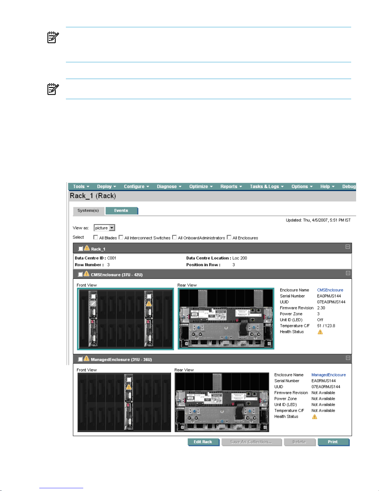
NOTE: For c-Class devices (blades and switches in an enclosure) to appear in HP BladeSystem Integrated
Manager tree or picture view, at least one Onboard Administrator in that enclosure must be discovered
before or after the devices. The devices may be discovered in HP SIM but do not appear in HP BladeSystem
Integrated Manager tree or picture view if none of the Onboard Administrators are discovered.
NOTE: Any change in the physical configuration of the c-Class enclosure, such as moving the devices from
one slot to another or removing a device, requires re-identification of the Onboard Administrator.
Navigating the System(s) tab
The picture view page for racks and enclosures contains a picture view of the discovered systems in the rack
or enclosure if available. The rack name appears along with a picture view, table view, or iconic view of
the rack. While signed in to HP Systems Insight Manager (HP SIM), placing your cursor over a server shown
in the view, displays information on that particular server, including server blade name, slot number, and
the enclosure in which the server is located. You can also click a component name to display detailed
information about the component. The System Page appears.
Navigating the System(s) tab 29
Page 30

The following items are listed on the Rack View page.
• Rack name in header. Displays the name of the rack.
• Updated: (Timestamp). Automatically refreshes and displays the last updated timestamp.
Note: This reflects the Central Management Server time and not the client time.
• Type of system in parentheses (rack). Displays the system type of in parenthesis.
• Help link. Click the help link, which is displayed as a question mark, to view the online help.
• View as dropdown list. Select from the following views:
Table.•
• Tree.
• Icons.
• Picture.
• Multi-select checkboxes. Select the device type based on the following:
All Blades•
• All Interconnect Switches
• All Onboard Administrators
• All Enclosures
• Front and rear views. Displays realistic front and rear picture views which include:
A collapsible tray for each enclosure in the rack, with the enclosure status and name in the title
bar
•
• Selection checkboxes on all selectable items
• Status icons on all items with status
• Each blade or switch hyperlinks to that system's System Page
• Enclosure details. Enclosure details to the right of the pictures include:
Enclosure Name. Click Enclosure Name to display the picture view of the enclosure.•
• Serial number. Displays the serial number of the system.
• Rack name. Displays the name of the rack.
• Unit ID (LED). Indicates whether the Unit ID is on or off.
• Health Status. Indicates the health status of the enclosure.
• Data Center ID. Indicates the identification number of the data center which the rack is part of.
• Data Center Location. Indicates the location of the data center which the rack is part of.
• Row Number. Indicates the row number of the rack.
• Position in Row. Indicates the position of the rack in the row.
The details such as Data Center ID, Data Center Location, Row Number and Position in Row are visible
only when you create a new rack or when you edit an existing rack.
The following details are shown for only c-Class enclosures:
•
Onboard Administrator
. Displays a link to the Onboard Administrator home page.
• Virtual Connect Manager. Displays the IP address to the Virtual Connect Manager (VCM). You
can click the IP address to access the VCM system.
• VCM Domain Name. Displays the VCM domain name. Click the domain name to view the Systems
page for the VC Domain.
• Firmware Revision. Displays the firmware revision number.
Note: This option is available for only p-Class collections.
30 Managing server blades from HP SIM
Page 31

• Power zone. Displays the power zone that the rack where the rack is located. An alert is displayed
if the power condition has changed. For example, an alert displays if an administrator removes
a power supply from an enclosure.
Note: This option is available for only p-Class collections.
• Temperature C/F. Displays the current temperature of the enclosure in degrees Celsius and
Fahrenheit.
Note: This option is available for only p-Class collections.
• Fan Redundancy. Displays Fan Redundancy status. Click Fan Redundancy to display the
Onboard Administrator home page.
Note: This option is available for only c-Class collections.
• Power Redundancy. Click Power Redundancy to display the Onboard Administrator home
page.
Note: This option is available for only c-Class collections.
• For power enclosures, the following additional information appears:
Load Balanced Cable. Indicates whether the load balanced cable is present.•
• Power Redundancy. Displays the Power Redundancy information for the enclosure only if the
iLO has firmware version 1.82 or later.
Note: This option is available for only p-Class collections.
NOTE: The enclosure is highlighted if at least one iLO in the rack using that power enclosure has
firmware version of 1.82 or higher.
While logged in to HP BladeSystem Integrated Manager in HP Systems Insight Manager, placing your cursor
over a component shown in the view, displays information on that particular component, including slot
number/bay number, blade server name/IP address, product model, and the enclosure in which the server
is located. If the bay is empty it displays as an empty bay. If the Firmware of the power enclosure is less
than 1.80, a question mark is displayed for each bay of the enclosure. When the cursor is moved over that
bay, it suggests to upgrade the Firmware to 1.80 or higher. You can also click a component to display
information about that component. The System Page appears. See System page for more information.
System List buttons
Three buttons at the bottom of the System(s) tab (picture view) are available to users with
full-configuration-rights
.
• Save As Collection. When a system is highlighted, this button is used to save the selection with a
new name. Changes are saved on a per-user, per-collection basis.
• Delete. This button is used to delete one or more systems from the
database
. Select the systems to be
deleted, and click Delete. A dialog box appears. Click OK to continue with the deletion or click Cancel
to cancel the operation.
• Print. When the report is displayed, select File→Print from the browser menu to print the report.
NOTE: Because certain print options are not supported in HP Systems Insight Manager, you cannot:
• Change the Orientation to Landscape in the Print dialog box (see Printing Problems in the
Troubleshooting section of HP Systems Insight Manager Technical Reference Guide for a workaround
to this issue)
• Cancel printing after the print job has been executed, but you can access the operating systems
print queue and cancel the print job
• Print to a file
Navigating the System(s) tab 31
Page 32
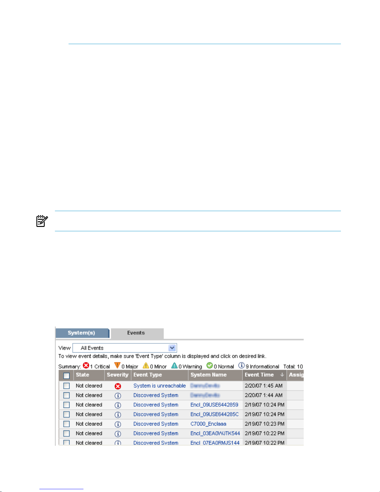
• Print selected systems, only entire list of systems
• Print the system table view page if you close the browser immediately after issuing a print request
Buttons are disabled if you do not have appropriate rights. However, the Print button appears for all users.
Save a collection
You can save a collection with a new name or to a specific location.
To save a collection:
1. In the Name field, enter a name for the collection.
2. Under Place in Folder, select where to save the collection (in a Private folder of one of the Shared
folders).
3. Click OK to save the collection, or click Cancel to cancel the save operation.
Deleting a Blade system
You can delete a Blade system from a rack.
1. On the system tab (picture view), select one or more systems to delete from the rack or enclosure by
selecting the checkbox associated with the system in the image displayed.
2. Click Delete. A dialog box appears, stating, Are you sure you want to delete these
systems?
3. Click OK to delete the systems, or click Cancel to return to the system tab (picture view) without deleting
the systems.
NOTE: Containers (for example, racks) must be empty before they can be deleted. Selecting a rack and
all its contained systems works without error.
Navigating the Event tab
The Events tab for c-Class racks or enclosures displays all current device
events
in the enclosure or rack in
table view.
The event table view page is divided into the following sections:
1. Filter Criteria
2. Event Status Legend
3. Event Collection Columns
4. Event Details
5. Event Management Buttons
32 Managing server blades from HP SIM
Page 33

From this page, you can clear, delete, and assign events, enter comments on the event, and view printable
reports.
Filter Criteria
The Event list can be filtered using the Filter Criteria dropdown list to view individual systems, such as
blades, switches or Onboard Administrator events, separately or you can view all events.
To filter the Event list:
1. From the Filter Criteria dropdown list, select a criteria:
• All Onboard Administrator Events Events that are reported by all Onboard Administrators included
in the selected rack or enclosure. This option is only available for c-Class racks or enclosures.
• All Blade Events Events that are reported by all blades included in the selected rack or enclosure.
This option is available for e-Class enclosures as well as p-Class and c-Class racks or enclosures.
• All Switch Events Events that are reported by all switches included in the selected rack or enclosure.
This option is available for p-Class and c-Class racks or enclosures.
• All Events Events that are exposed by all devices in the selected rack or enclosure. This option
is available for p-Class and c-Class racks or enclosures.
2. The filtered Event list appears.
Event Status Legend
The legend shows how many events in the view are Critical, Major, Minor, Normal, and Informational.
Event Details
The event collection can be displayed by clicking:
• An event collection from the Systems and Events panel
• An event status icon in the System Status panel
• The All Events Associated with this System link from the System Page
• A private event collection
• A hyperlink in the Uncleared Events section on the System Overview page
Event collections are filtered based on authorizations. Users can only view events on
systems
for which they
have the appropriate authorization.
When HP Storage Essentials is installed, a link in this section allows you to view the corresponding event
details in HP Storage Essentials.
Event Collection Columns
Sort collection results by a particular column, click the column header for ascending or descending order.
Place your cursor over a column name for a brief description of the column.
The following columns are displayed:
• Selection
• State
• Severity
• Event Type
• System Name
• Event Time
• Assigned To
• Comments
• System Type
Navigating the Event tab 33
Page 34

• Rack Name
• Enclosure Name
Selection
Select the checkbox in this column to select an event. You can select more than one event. Select the checkbox
in the column heading to select or deselect all displayed events.
State
This column displays whether the event is in the Cleared or Not Cleared state. Events start in the Not Cleared
state. A Cleared state means the user is no longer interested in this event. Event states also include In Progress,
indicating not all the data for the event has been logged. Events in an In Progress state cannot be removed
or cleared. A restart of the HP SIM
CMS
moves any pending state events to Not Cleared.
Severity
This column displays the event status icon to indicate the severity of a problem represented by the event.
Event Type
This column displays the type of an event. Some examples are SNMP traps, login failures, or the replicate
agent settings too. Select an event type from the list to view the Event Details section. The information
displayed varies depending on the event. If you cannot see the entire event type in the column, place your
cursor over this field, and a popup window is displayed that shows the entire event type name.
System Name
This column displays the name of the system on which the event occurred. Clicking a link in this column
displays the System Page for the selected system.
When an event occurs that affects an entire
rackorenclosure
, it is possible for several systems in that rack
or enclosure to generate a trap for that event. These
container
traps are filtered such that only one event is
logged per rack or enclosure trap. Also, even though the source of the trap may be a
blade server
or
management processor, HP Systems Insight Manager sets the Event Source and Associated System for
the logged event to the rack or enclosure, as appropriate.
Event Time
This column displays the time stamp when the HP SIM
CMS
received this event, which includes the date and
time. If the system is in a different time zone than the event time (CMS time), the event time is converted to
the system time zone.
Assigned To
To assign responsibility for an event to a user, select the event, and click Assign to at the bottom of the
page. The Assign to section appears, which enables you to select to assign a new assignee or use an
existing assignee. If you select to use an existing assignee, you can only select one user name from the list.
This name does not have to be a user with privileges on the system or a name that can be used to log into
the CMS. This field is free-form text.
Comments
This column either displays any existing comments for this event or is blank if no comments have been entered.
Comments are truncated in the column itself. Click the event type to view the entire comment if needed, or
place your cursor over a comment field, causing a pop-up window that shows the entire comment to appear.
System Type
This column displays system types such as enclosure or rack.
Rack Name
This column displays the name of the rack.
34 Managing server blades from HP SIM
Page 35

NOTE: This column displays when the system is a rack or enclosure.
Enclosure Name
This column displays the name of the enclosure.
NOTE: This column displays when the system is a rack or enclosure.
Event Management Buttons
Five buttons at the bottom of the event table view page are available to users with
full-configuration-rights
only. These buttons might not appear depending on where you access this page from. For example, when
creating a task and selecting targets, there are no buttons displayed, only the table or system names.
• Clear. This button is used to clear one or more events from the
database
. Select the events to clear,
and click Clear.
• Delete. This button is used to delete one or more events from the database. Select the events to be
deleted, and then click Delete. A dialog box appears. Click OK to continue with the deletion, or click
Cancel to cancel the deletion.
• Assign to. This button is used to assign responsibility for events to a particular user.
• Enter Comments. Brings up a dialog box to enter comments for one or more events.
• Print. When the report is displayed, select File→Print from the browser menu to print the report.
Buttons are disabled if you do not have appropriate privileges. However, the print button is displayed for
all users.
Viewing enclosures
The picture view page for enclosures contains a diagram of the discovered systems in the enclosure if
available. The enclosure name appears along with a picture view, table view, or iconic view of the enclosure.
While signed in to HP Systems Insight Manager (HP SIM), placing your cursor over a server shown in the
view, displays information on that particular server, including server blade name, slot number, and the
enclosure in which the server is located. You can also click a server name to display information about the
server. The System Page appears.
The following systems are displayed in the picture view for racks and enclosures:
• Servers, desktops and workstation blades
• Interconnect modules
• Power supply enclosure
Note: Provided for p-Class only.
• Onboard Administrator, fans, and power units
Note: Provided for c-Class only.
Slots that have no server or desktop identified and no interconnect switch identified are also displayed in
the picture view for enclosures.
The following sections are displayed in the picture view for racks and enclosures:
• System Status
Health Status icon. Represents the health of a system including Critical, Major, Minor, or Normal.•
• Identification
Enclosure Name. Displays the name of the enclosure. You can click Printable Enclosure Details
to display a printable table that includes the following enclosure details for:
•
• Onboard Administrators:
Bay•
• System Name
Viewing enclosures 35
Page 36

• IP Address
• Model
• Firmware Version
• Role
• Servers:
Bay•
• System Name
• IP Address
• Model
• Management Processor IP
• Management Processor Firmware Version
• Insight Management Agent Version
• System ROM Version
• Operating System
• IPv6 Address
NOTE: The IPv6 Address displays the address when IPv6 is enabled on the server
and Not Available when IPv6 is disabled.
• Switches:
• Bay
• System Name
• IP Address
• Model
• Media Type
• Serial Number. Displays the serial number of the enclosure.
• UUID. A unique identifier from the agent or other instrumentation on the system.
• Rack Name. Click to display the rack in picture view.
• Unit ID (LED). Indicates whether the Unit ID is on or off.
•
Onboard Administrator
- Click the Onboard Administrator link to display the Onboard Administrator
home page.
Note: The Onboard Administrator link appears only for c-Class enclosures.
• Virtual Connect Manager. Displays the IP address to the Virtual Connect Manager (VCM). You
can click the IP address to access the VCM system.
Note: This option appears only when a Virtual Connect is available.
• VCM Domain Name. Displays the VCM domain name. Click the domain name to view the System
page of the VC Domain.
• For c-Class enclosures:
Power and Thermal section•
• Power Redundancy. Displays Power Redundancy status. Click Power Redundancy to
display the Onboard Administrator home page.
• Fan Redundancy. Displays Fan Redundancy status. Click Fan Redundancy to display the
Onboard Administrator home page.
36 Managing server blades from HP SIM
Page 37

• Enclosure Ambient Temperature. Displays the following:
Status. Displays the current status in icon form.•
• C/F. Displays the current temperature in degrees Celsius and Fahrenheit.
• Graph. Displays a graph depicting the temperature.
• The following information displays for each power unit present in the enclosure:
• Bay Number. Displays the number assigned to the bay.
• Firmware Revision. Displays the firmware revision number.
• A/C Input. Indicates the health status of the power unit.
• Phase. Displays the phase.
• Serial Number. Displays the serial number of the power unit.
• Part Number. Displays the part number for the power unit.
• Power Consumption. Displays the power consumption in watts to include:
• Output/Capacity. Displays the current output verses the capacity.
• Graph. Displays a graph depicting the output verses the capacity.
• Fans section
Bay. Displays the bay number.•
• Health Status. Displays the health status of the enclosure.
• Part Number. Displays the part number for the fan.
• Power Used (Watts). Displays the amount of watts currently used.
• Speed (RPM). Displays the current speed in RPMs.
NOTE: From this page, you can also view the enclosure details in a separate window. Select the
enclosure name on the page and click Printable Enclosure details. A new window displays the details
of the enclosure.
• For p-Class enclosures:
Power and Thermal section
The following items are displayed on the Enclosure View for a Power Enclosure if at least one
iLO in the rack using that power enclosure has firmware version of 1.80 or higher.
•
• Load Balanced Cable. Indicates whether the load balanced cable is present.
• Power Redundancy. Displays Power Redundancy status.
• Temperature A. Displays overall temperature in the left section of the power enclosure.
• Center Temperature. Displays overall temperature in the center section of the power
enclosure.
• Temperature B. Displays overall temperature in the right section of the power enclosure.
• The following information displays for each power unit present in the enclosure:
• Bay Number. Displays the number assigned to the bay.
• Firmware Revision Displays the firmware revision number.
• A/C Input. Indicates the health status of the power unit.
Viewing enclosures 37
Page 38

• Input Temperature. Displays the following:
Status. Displays the status of the input temperature.•
• C/F. Displays the current temperature in degrees Celsius and Fahrenheit.
• Graph. Displays a graph depicting the Trip temperature verses Fail temperature.
• Output Temperature. Displays the following:
• Status. Displays the status of the output temperature.
• C/F. Displays the current temperature in degrees Celsius and Fahrenheit.
• Graph. Displays a graph depicting the Trip temperature verses Fail temperature.
While logged in to HP BladeSystem Integrated Manager in HP Systems Insight Manager placing your cursor
over a component shown in the view, displays information on that particular component, including slot
number/bay number, server blade name/IP address, product model, and the enclosure in which the server
is located. If the bay is empty it displays it as an empty bay. If the Firmware of the power enclosure is less
than 1.80, a question mark is displayed for each bay of the enclosure. When the cursor is moved over that
bay, it suggests to upgrade the Firmware. You can click a component in the picture view to display information
about that component. The System Page appears. See System page for more information. However, if you
click the status icon that is displayed on the component in the picture view, you remain on the Enclosure
View page.
There are three buttons at the bottom of the picture view page are available to users with full configuration
rights.
• Save As Collection. When a system or group of systems is selected, this button is used to save the
selection with a new name. Changes are saved on a per-user.
• Delete. This button is used to delete one or more systems from the database. Select the systems to be
deleted, and click Delete. A dialog box appears. Click OK to continue with the deletion or click Cancel
to cancel the operation. The picture view is refreshed.
NOTE: Only systems can be deleted from the picture view. If a collection is selected, the Delete
button becomes disabled. Collections must be deleted through the Customize Collections page.
NOTE: If a VM Host is deleted, it can still be accessed through the Virtual Machine Management
Pack console, and the operations that can be performed on a VM Host are not affected by the deletion
of the HP Systems Insight Manager (HP SIM) system. The Virtual Machine Management Pack console
continues to show the HP SIM status.
NOTE: If you select a collection by checking Select "collection name" collection itself, the Delete
button is disabled. To delete collections, go to the Customize Collections page.
• Print. Click Print to display a printable version of the picture. Print the picture from the browser by
clicking File→Print.
Print is available regardless of your rights, however the other options are only enabled if you have
appropriate rights.
Viewing an enclosure
To view an enclosure or power enclosure, click an enclosure collection in picture view or click Enclosure
Name in the Rack view. The Enclosure View page is displayed in picture view. The picture view page for
enclosures contains an image of the discovered enclosure with the discovered servers residing in the enclosure.
38 Managing server blades from HP SIM
Page 39
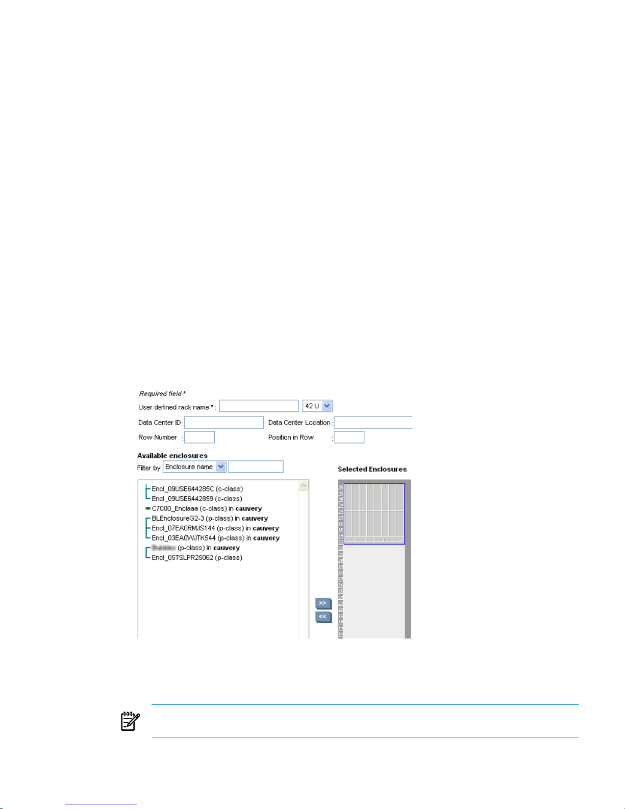
Creating a rack
When HP Systems Insight Manager (HP SIM) discovers devices with rack information such as iLO or OA,
enclosures and racks are created. You can edit these racks using the rack view. The racks that you created
in the previous release are all available under the All Racks option. You can add the enclosure to these
previously created racks or create new racks and add enclosures to them. After you create these racks, they
are listed under the All Racks option. The options All p-Class Racks and All e-Class Racks options are no
longer available.
To create a rack:
Except for e-Class racks, all other racks are automatically created when they are discovered. To add an
e-Class enclosure to a rack, use the following procedure.
1. To access the picture view, navigate to All e-Class Enclosures, All c-Class Enclosures or All
p-Class Enclosures.
2. Click an enclosure. The enclosure picture view appears.
Note: In an enclosure under the Identification section, if the Rack name displays Not Available then
the enclosure is not included in any rack.
3. To add the enclosure to a new rack, click Add Enclosure to a rack. The Add to rack dropdown list
appears.
Note: This option is only available if an enclosure is not associated with a rack.
4. Select Add to new rack from the Add to Rack dropdown list and click GO. The Edit Rack page
appears. When a new rack is created from an enclosure view, the enclosure is automatically added to
the Selected enclosures section.
Note: The Add to Rack dropdown list also lists the racks that were previously created. To add an
enclosure to an existing rack, select the rack name and click GO.
5. To create a rack, you must add the following details:
• Rack Name. Enter a name for the new rack. You can use this rack name to search for the rack
later. This is a required field.
NOTE: The name you enter for the rack can differ from the rack name maintained by the enclosure
or the management processor.
• Rack Height. Select the height of the rack from the dropdown list.
Viewing enclosures 39
Page 40
• Data Center ID. Enter an ID for the data center. This ID can be alphanumeric and can include
hyphens and underscores (- and _) only.
• Data Center Location. Enter the location of the data center. It can be the geographic location or
the actual physical location of the data center.
NOTE: You can use the Data Center ID and Data Center Location details to search the rack
later.
• Row Number. Enter the row number where the rack is located. You can enter only numerals for
this field.
• Position in Row. Enter the position in the row where the rack is located. You can enter only
numerals for this field.
6. From the Available Enclosures dropdown list, select the filter by which you want to view the list of
enclosures. You can select All Enclosures or Class. You can filter the collection by entering a class.
For example, if you enter
p-Class
, then all p-Class enclosures are available to be added to the rack.
7. Select one or more of the relevant enclosures and click the >> symbol to add them to the rack. You can
click << to remove enclosures from the rack. You can also drag and drop the enclosure in the desired
position within the rack.
Note: indicates enclosures which are daisy chained.
8. Click Save. The enclosure is added to the rack and the picture of the new rack with the added enclosure
appears. If an enclosure has already been added to another rack, a message appears indicating the
enclosure is already assigned to another rack. You can confirm your intention to remove the enclosure
from the existing rack and it is added to the new rack. You can click Cancel to discard the rack and
close the window.
Editing a rack
From the picture view of a rack, you can edit the rack to add or remove enclosures.
To edit a rack:
1. To access the picture view, navigate to All Racks and select the rack to be edited and click Edit Rack.
The Rack View page appears.
Note: The rack can be edited and deleted only from the picture view.
2. To edit a rack, you can change any of the following details:
• Rack Name. Enter a name for the new rack. You can use this rack name to search for the rack
later.
• Rack Height. Select the height of the rack from the dropdown list.
• Data Center ID. Enter the data center ID. This ID can be alphanumeric and can include hyphens
and underscores (- and _) only.
• Data Center Location Enter the data center location. It can be the geographic location or the
actual physical location of the data center.
NOTE: You can use the Data Center ID and Data Center Location details to search the rack
later.
• Row Number. Enter the row number where the rack is located. You can enter only numerals for
this field.
• Position in Row. Enter the position in the row where the rack is located. You can enter only
numerals for this field.
3. From the Available Enclosures dropdown list, select the filter by which you want to view the list of
enclosures. You can select All Enclosures or Class.
40 Managing server blades from HP SIM
Page 41

4. Select one or more of the relevant enclosures and click the >> symbol to add them to the rack. You can
click << to remove enclosures from the rack.
Note: indicates enclosures which are daisy chained.
5. Click Save. The enclosure is added to the rack and the picture of the new rack with the added enclosure
appears. If an enclosure has already been added to another rack, a message appears indicating the
enclosure is already assigned to another rack. You can confirm your intention to remove the enclosure
from the existing rack and it is added to the new rack.
Saving an Onboard Administrator configuration
You can save the current settings of a c-Class enclosure as a configuration script. After you save this
configuration file, you can always upload this configuration script using the Onboard Administrator to revert
to the previous settings of the enclosure. When you save a configuration file, you must provide a file name
that is unique to that enclosure. Also, you can save multiple configuration scripts for a single c-Class enclosure.
To save a c-Class enclosure configuration:
1. From the Tools and Links page of the Onboard Administrator, click Save/Restore Configuration
of Onboard Administrator.
Note: You can access this option from Save or Restore Onboard Administrator settings in the
Configure section.
2. Enter the user name and password for the Onboard Administrator. The Save/Restore Configuration
Script page appears.
3. Enter a unique name for the configuration script and click Save. The name must meet the following
conditions:
• Alphanumeric and can contain special characters such as underscores and periods.
• Must start with an alphabet character.
The configuration script is listed in the Restore Configuration section.
Restoring an Onboard Administrator configuration
You can restore the previous settings of an enclosure by selecting the respective configuration script that you
had saved earlier.
To restore a c-Class enclosure configuration:
1. From the Tools and Links page of the enclosure, click Save/Restore Configuration of Onboard
Administrator.
2. Enter the user name and password for the Onboard Administrator. The Save/Restore Configuration
Script page appears.
3. In the Restore Configuration section, select the file that includes the configuration settings that you
want to restore.
4. Click Restore. The settings of the enclosure are restored.
Deleting a configuration script
You can delete a configuration script.
To delete a c-Class enclosure configuration:
1. From the Tools and Links page of the enclosure, click Save restore OA configuration and select
the configuration script to be deleted and click Delete.
Note: You can select multiple configurations and delete them simultaneously.
2. Click Back from the browser to navigate to the Tools/Links page of the Onboard Administrator.
Viewing enclosures 41
Page 42

42
Page 43

4 Monitoring and controlling servers
This chapter provides an overview for using Insight Control Environment software to manage server power
consumption through Insight Power Manager, and ensure and monitor server health and performance
through HP Performance Management Pack (PMP).
Configuring Insight Power Manager options
IMPORTANT: When Insight Power Manager is installed it is disabled. To enable Insight Power Manager,
select Options→Insight Power Manager Options, and then select Enable Insight Power Manager
Plug-In.
The Insight Power Manager Options menu enables you to configure HP Insight Power Manager settings
and display options.
The Insight Power Manager Options menu enables you to:
• Enable or disable HP Insight Power Manager capabilities on managed systems. If disabled, no network
activity related to the gathering of power data is performed. This setting is global and affects all users.
• Configure up to five iLO 2 username and password pairs for access to managed systems. You can also
configure an alternate SSL port number. This setting is global. The default setting is 443.
• Configure a designated time period to keep historical data. The data is deleted automatically after the
specified time period has elapsed. This setting is global.
• Indicate whether to display temperature in Celsius or Fahrenheit. This setting is configured by the user.
• Indicate whether to display power for in watts or Btus. This setting is configured by the user.
To configure IPM options:
1. Click Options Insight Power Manager Options. The Insight Power Manager Options page appears.
2. To enable HP Insight Power Manager, select Enable HP Insight Power Manager Plug-In.
3. The Graph and Analysis Settings section provides the following options:
• Temperature Unit of Measurement—Select a unit of measurement for the temperature from the list.
Choices include Fahrenheit and Celsius. This setting is configured by the user.
• Power Unit of Measurement—Select a unit of measurement for power from the list. This setting is
configured by the user.
• Use GMT for all timestamps in the graphs—Select this option if you want to use Greenwich Mean
Time (GMT) when graphing data. This setting is configured by the user.
• Cost of Power per kWh—Enter the average cost of power per kilowatt-hour. This box is used to
calculate the cost of operation for the server and cooling. For ease of data entry, only one box is
provided. If more cost analysis is required, use the Export option in the Power Regulator Actions
section of the graphs. This box is used to calculate the cost and annual cost of operation for the
server and cooling. This setting is configured by the user.
• Currency Type—Enter the currency type. This box is used for display purposes only and is used in
the Analysis section of the graphs that display cost information. The default value is USD, but the
value can be changed to $, EUR, €, GBP, £, ITL, JPY, ¥, or any other printable character set that
represents your currency. This setting is configured by the user.
• Cooling Multiplier—Enter a cooling multiplier. This value represents the relative cost of cooling the
server compared to the cost of powering the server. The default value of 1.5 indicates that it costs
1.5 times as much to cool the server as it does to power the server. This value is multiplied by the
kilowatt-hours used by the server to arrive at a cooling kilowatt-hours value used in the Analysis
section of the graphs that display power consumption information. This setting is configured by
the user.
• Power Line Voltage—Select the power line voltage from the dropdown. This box is used to calculate
the amperage consumed value in the Analysis section of the graphs that display power consumption
information. This setting is configured by the user.
Configuring Insight Power Manager options 43
Page 44

4. The Default Integrated Lights Out Settings section enables you to configure a Secure Socket Layer
(SSL) port number and provide login credentials for up to five managed systems.
• The following options are available. The settings are global and affect all users:
• Default SSL Port—Enter the SSL port number to be used by IPM to communicate with iLO 2. The
default is 443.
• User Name—Enter the user names used to connect to the iLO 2 for the managed systems. You can
enter up to five user name and password pairs in the Default 1-5 boxes.
• Password—Enter the password for the previously named managed system iLO 2.
• Confirm password—Re-enter the password for the iLO 2 of the managed system exactly as you
entered it in the Password box.
NOTE: IPM tests each name and password pair on managed systems until it successfully accesses
power data.
5. The Default Power Regulator Data Expiration Settings section enables you to configure how long
to keep historical data.
In the first Remove data older than list, select the time to be selected in the second list. For example,
you can select Remove data older than 6 Month(s). All data that is 6 months or older is removed
permanently.
6. To save your settings, click Apply.
Using the iLO browser interface
The iLO 2 browser interface enables easy access to daily tasks through a selection of tabs. Each tab groups
similar tasks for easy navigation and work flow. Typical tabs used are System Status, Remote Console,
and Virtual Devices.
Using the System Status tab
The System Status tab displays the following options:
• Summary—The Summary tab displays high-level details about the system and iLO 2 subsystems and
links to commonly used features.
• System Information—The System Information tab displays the health of the monitored system. Many
features necessary to operate and manage the components of HP ProLiant servers migrated from the
health driver to the iLO 2 microprocessor.
• System Information Summary—The System Information Summary tab displays the state of monitored
host-platform subsystems status at a glance, summarizing the condition of all the monitored subsystems,
including overall status and redundancy (the ability to handle a failure). The subsystems can include
fans, temperature sensors, power supplies, and voltage regulator modules.
• Fans—iLO 2, working with additional hardware, controls the operation and speed of the fans. Fans
provide essential cooling of components to ensure reliability and proper operation.
• Temperatures—The Temperatures tab displays the location, status, temperature, and threshold settings
of temperatures sensors in the server chassis. The temperature is monitored to maintain the location
temperature below the caution threshold. If one or more sensors exceed this threshold, iLO 2 implements
the recovery policy to prevent damage to server components.
• Power—The VRMs/Power Supplies tab displays the state of each VRM (voltage regulator module) or
power supply. VRMs are required for each processor in the system. VRMs adjust the power to meet the
needs of the processor supported. A VRM can be replaced if it fails. A failed VRM prevents the processor
from being supported.
• Processors—The Processors tab displays the available processor slots, the type of processor installed
in each slot, and a brief status summary of the processor subsystem. If available, installed processor
speed (in MHz) and cache capabilities appear.
• Memory—The Memory tab displays the available memory slots and the type of memory (if any) installed
in the slot.
44 Monitoring and controlling servers
Page 45

• NIC—The NIC tab displays the MAC addresses of the integrated NICs. This tab does not display add-in
network adapters.
• iLO 2 Log—The iLO 2 Log tab displays the iLO 2 Event Log, which is a record of significant events
detected by iLO 2. Logged events included major server events, such as a server power outage or a
server reset, and iLO 2 events such as unauthorized login attempts.
• IML—The IML tab displays the Integrated Management Log, which is a record of historical events that
have occurred on the server as reported by various software components. Events are generated by the
system ROM and by services such as the System Management (health) driver.
• Diagnostics—The Diagnostics option displays the Server and iLO 2 Diagnostics screen which
provides iLO 2 self-test results and a reset iLO 2 option, as well as comprehensive diagnostic information.
• Virtual NMI (non-maskable interrupt) button—This button halts the operating system for debugging
purposes. This function is an advanced feature and only used for kernel-level debugging.
• iLO 2 self-test results—iLO 2 performs a series of initialization and diagnostic procedures on the
subsystems of the iLO 2 system. The results appear on the Server and iLO 2 Diagnostics tab. All
tested subsystems should display Passed under normal situations. Any test can display one of three
results: Passed, Fault, or N/A.
• Insight Agents—The HP Insight Management Agents support a browser interface for access to runtime
management data through the HP System Management Homepage. The HP System Management
Homepage is a secure web-based interface that consolidates and simplifies the management of
individual servers and operating systems. By aggregating data from HP Insight Management Agents
and other management tools, the HP System Management Homepage provides an intuitive interface
to review in-depth hardware configuration and status data, performance metrics, system thresholds,
and software version control information.
Using the Remote Console tab
The Remote Console tab provides access to different views of the Remote Console and enables you to
define keystroke sequences that are transmitted to the remote host server by pressing a hot key. iLO 2 uses
virtual KVM technology to prove remote console performance that is on-par with other KVM solutions.
While standard iLO 2 enables remote console access from server power-on through POST, it might require
an optional license key to continue to access the server console from there. For more information, see the
HP Integrated Lights-Out 2 User Guide
. The Remote Serial Console is available without an additional license
and is suitable for host operating systems that do not require access to the graphical console.
The Graphical Remote Console turns a supported browser into a virtual desktop, giving you full control over
the host-server display, keyboard, and mouse. The operating system-independent console supports graphic
modes that display remote host server activities, including shutdown and startup operations.
• Integrated Remote Console Fullscreen—Enables you to resize the IRC to the same display resolution as
the remote host. To return to your client desktop, exit the console.
• Integrated Remote Console option—Offers a high-performance remote console interface for Windows
clients, combining KVM, Virtual Power, and Virtual Media functionality. The Integrated Remote Console
option is an ActiveX control that runs from Internet Explorer.
• Remote Console Information screen—Appears when you click the Remote Console tab of the iLO 2
web browser-based interface, this screen shows all available Remote Console options and a link to
download an updated Java™ Runtime Environment.
• Remote Console display—Redirects the host server console to the network client browser, providing
full-text (standard) and graphical mode video, keyboard, and mouse access to the remote server (if
licensed with iLO 2).
• Remote Serial Console—Enables you to access a VT320 serial console from a Java applet-based console
connected to the iLO 2 Virtual Serial Port, with a broad browser compatibility that includes Windows
and Linux browsers.
• Acquiring the Remote Console—Displays the Acquire button when the Remote Console Acquire
setting on the Remote Console Settings screen is enabled. If you have opened the Remote Console
page and are notified that another user is using Remote Console, to end the other user’s Remote Console
session, click Acquire, and then in your current window, start a Remote Console session.
Using the iLO browser interface 45
Page 46

• Optimizing mouse performance for Remote Console or Integrated Remote Console—Enables you to set
the mouse acceleration, which must be set correctly for the remote console to behave properly in certain
Windows configurations.
• High-performance mouse settings—Enables the High Performance Mouse feature when using the Remote
Console. This feature improves pointer performance and accuracy on Windows Server 2003 and
Windows 2000 Service Pack 3 or later.
Using the Virtual Devices tab
The Virtual Devices tab provides the following options:
• Virtual power button—Enables control of the power state of the remote server and simulates physically
pressing the power button on the server. If the remote host server is not responding, this feature enables
an administrator to initiate a cold or warm reboot to bring the server back online.
• Power Regulator for ProLiant—Enables you to view and modify power regulation settings and view
processor states and power meter readings.
• Virtual media—Enabled by licensing the optional iLO 2. If the iLO 2 is not licensed, the following
message appears: iLO 2 feature not licensed.
• Virtual indicators—The Unit ID LED is the blue LED on the HP server that is used for identifying systems
in a rack of servers. iLO 2 enables you to view the status of the Unit ID LED and change the status using
iLO 2 Web pages.
Monitoring PMP parameters
Servers are monitored based on monitoring parameters. The monitoring status and the number of samples
must be configured in PMP for servers to be monitored.
Default PMP settings
The following are default monitoring settings:
1. Monitor and Alert selected
2. Number of samples to determine status - 5
The default monitoring settings can be changed on the Monitoring Administration page.
Sample rate
NOTE: Sample rate is populated automatically.
PMP does not control the amount of time between samples. Instead, the sample rate (data collection interval)
is set from within the HP Management Agents.
After you start monitoring a server, the sample rate that appears on the Monitoring Administration page is
synchronized to equal the sample rate of the agents for the monitored server.
The servers connected to an enclosure determine the sample rate for a network storage enclosure. The sample
rate for the storage enclosure is the highest sample rate of the connected servers.
Number of samples
PMP enables you to specify the number of samples from which the monitoring service calculates a running
average of gathered entries to determine system performance status.
Using the PMP interface
This section provides an overview of PMP functionality. A usage scenario demonstrates setup, administration,
and server monitoring.
46 Monitoring and controlling servers
Page 47
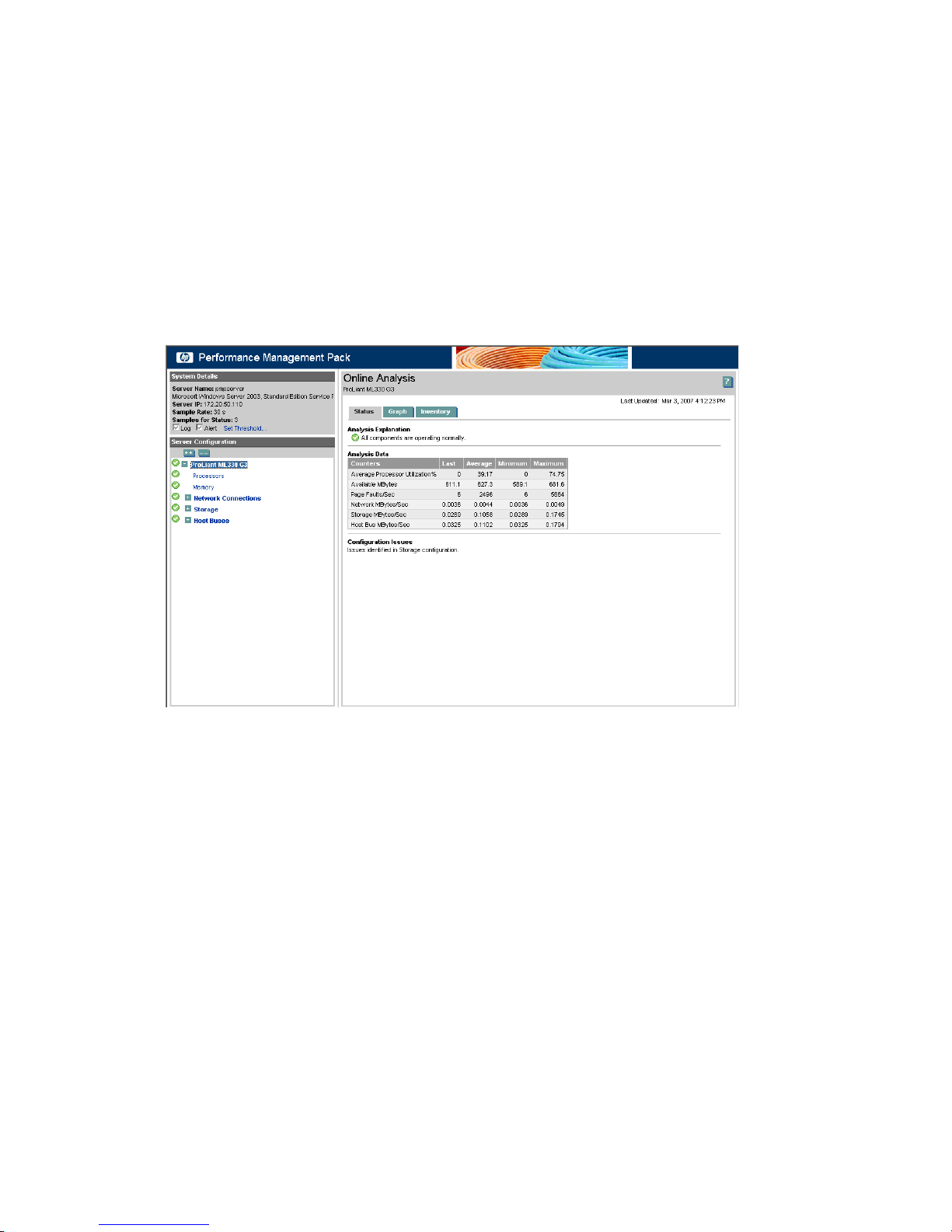
Online and Offline Analysis
The PMP Online and Offline Analysis tools provide an intuitive interface to detail the performance status and
inventory of monitored servers and processor memory, local and external storage, network storage, network
connections, host bus, and virtual machine host components for each server. The tools provided for Online
and Offline Analysis are similar in overall functionality. The major difference in performing Offline Analysis
is that the data comes from a database rather than a real-time data stream.
Additionally, for performance analysis in a static setting, PMP provides many tools to assist in monitoring
server performance. For more information about Offline Analysis, see the Offline Analysis section in this
guide.
When you select a monitored server icon from the PF column of the Systems Insight Manager console or
when you select Diagnose→Performance Management Pack→Online Analysis from the console toolbar,
the PMP Online Analysis screen appears in a new browser window, as shown in the following screen. The
analysis starts in the performance status view for the server.
Systems detail frame
The Systems detail frame appears at the top left side of the browser window below the banner and provides
the following information:
1. Server name - Displays the name of the server currently being monitored
2. Server OS - Displays the operating system version of the server currently being monitored
3. Server IP - Displays the IP address assigned to the server currently being monitored including IPv6
address for the NIC if available
4. Sample Rate - Displays the frequency with which the agents are collecting performance data on the
monitored server
5. Samples for Status - Displays the number of samples averaged to determine system performance status
6. Alert - Indicates if alerts are to be sent when certain server performance status conditions occur
7. Log - Indicates if the performance data is currently being logged for the selected server
8. Set Threshold - Provides a link for modifying the performance threshold values for the selected server
Server Tree frame
The Server Tree frame appears on the left side of the browser window. This frame is used to navigate between
system components. Component performance and status information appear in a hierarchical tree with nodes
for each level of the component. This frame provides a view of the server, processors, memory, network
connections, storage, host bus components, and virtual machine host components.
Online and Offline Analysis 47
Page 48
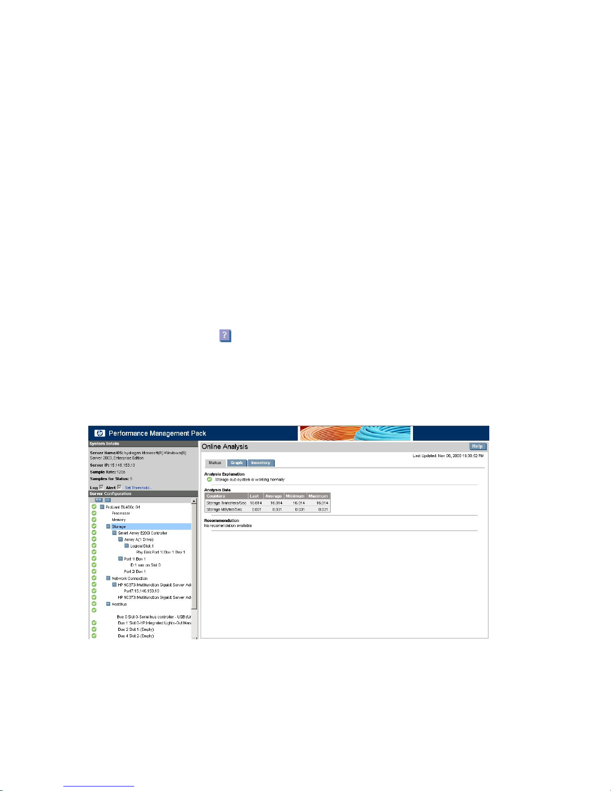
Results frame
The Results frame displays the status, inventory, and graphical representation for the selected server and its
components. Use the tabs in the Results frame to switch between these views. A list of the values corresponding
to each server and its components is provided in the PMP measurement categories section of this guide.
The Results frame includes tabs to access the different representations of the information available for the
server and its components. The tabs provide the following general information:
1. Status - Lists the performance counters (metrics) associated with the selected component. The table
provides the average, maximum, minimum, and last (current) values for all the counters. A status icon
indicates the performance of the component. An increasing level of severity is indicated as the status
changes from normal to major. The Status tab includes:
a. Analysis Explanation - Explaining why a bottleneck exists
b. Recommendation - Providing possible actions to relieve the bottleneck
c. Configuration Issues - Providing details about any issues detected for the components
The server metrics and their definitions for data analyzed by PMP to determine the status of a
particular component are provided in the PMP measurement categories section of this guide.
2. Graph - Displays a graphical representation of the performance metrics associated with the selected
component. The graph is dynamic, changing as the values change, and contains the last 25
measurements taken.
3. Inventory - Displays information about the selected component configuration, such as the processor or
NIC configuration. Information provided in the Inventory view is detailed in the PMP measurement
categories section of this guide.
The Results frame provides the icon in the top right corner, which displays a context-sensitive help page.
Storage Analysis
Storage Online Analysis appears as a node in the left tree under the server. Unlike the PMP 4.x versions,
there is no separate Network Storage Tab. The storage and its sub-components are show as a part of the
system tree on the left pane of the Online Analysis and Offline Analysis pages..
The usage scenario provides examples of bottleneck conditions with and without a recommended hardware
upgrade, as well as examples of static and offline analysis.
PMP Reports
PMP can generate reports illustrating the percentage of time a system was in a bottleneck state and the
overall performance utilization for a system categorized by its components. A System Summary Report can
be generated from data in the performance database in HTML format. CSV File Generator can generate
48 Monitoring and controlling servers
Page 49
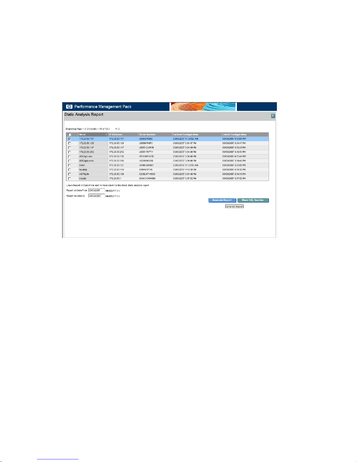
comma-separated value (CSV) files for import into desktop analysis or reporting tools. A Static Analysis
Report is an analysis of the hardware configuration for the server as a whole, identifying potential problem
areas. The Server availability report in the HTML format consolidates information on availability of servers
at any point in time.
The CSV file documents each individual sample for every component analyzed, collecting different
measurements for each. All report formats can generate reports for either one designated system or a group
of systems as a whole.
For a sample CSV file and a list of associated values measured for each server and its components, see the
Sample PMP CSV file section in this guide. This section also includes a sample System Summary report and
Static Analysis report.
The reports that are generated through PMP are stored in
C:\Program Files\HP\Performance Management Pack\Reports
This is the default location for the generated reports.
Offline Analysis
Offline Analysis is used to view recorded data sessions from the database, enabling review of specific
logged information sampled from the database. For more information about using Offline Analysis to view
recorded data sessions, see the Online and Offline Analysis section in this guide.
Offline Analysis 49
Page 50
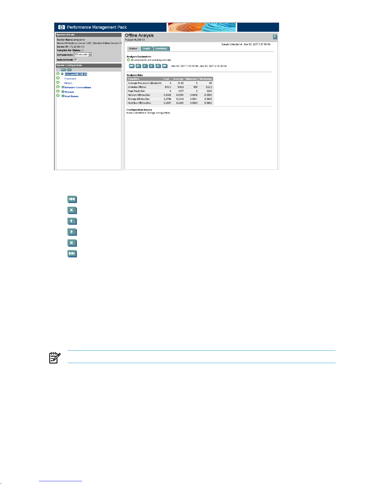
During the session, data is shown in the Manual refresh mode, which enables you to advance the samples
manually. To enable manual mode, click any navigation button. Manual mode navigation buttons include:
1. To the first sample
2. To the previous bottleneck
3. To the previous sample
4. To the next sample
5. Forward to the next bottleneck
6. To the latest sample
Manual Log Purge
Manual Log Purge enables the recorded sessions for a logged server or network storage enclosure, logged
in the PMP performance database and occupying hard disk storage space, to be deleted. Use this tool
regularly to remove unwanted recorded sessions and reduce database size.
To delete records in the performance database:
1. From the Systems Insight Manager console toolbar, select Options→Performance Management Pack
Options→Manual Log Purge.
2. Select the checkbox next to the server or network storage enclosure for which to delete logged data.
3. Specify to delete data older than a specified number of days or a specified date.
NOTE: You cannot delete the acquired data for the current date of the analysis server.
4. To remove the data from the performance database, click Delete Selected Data.
50 Monitoring and controlling servers
Page 51
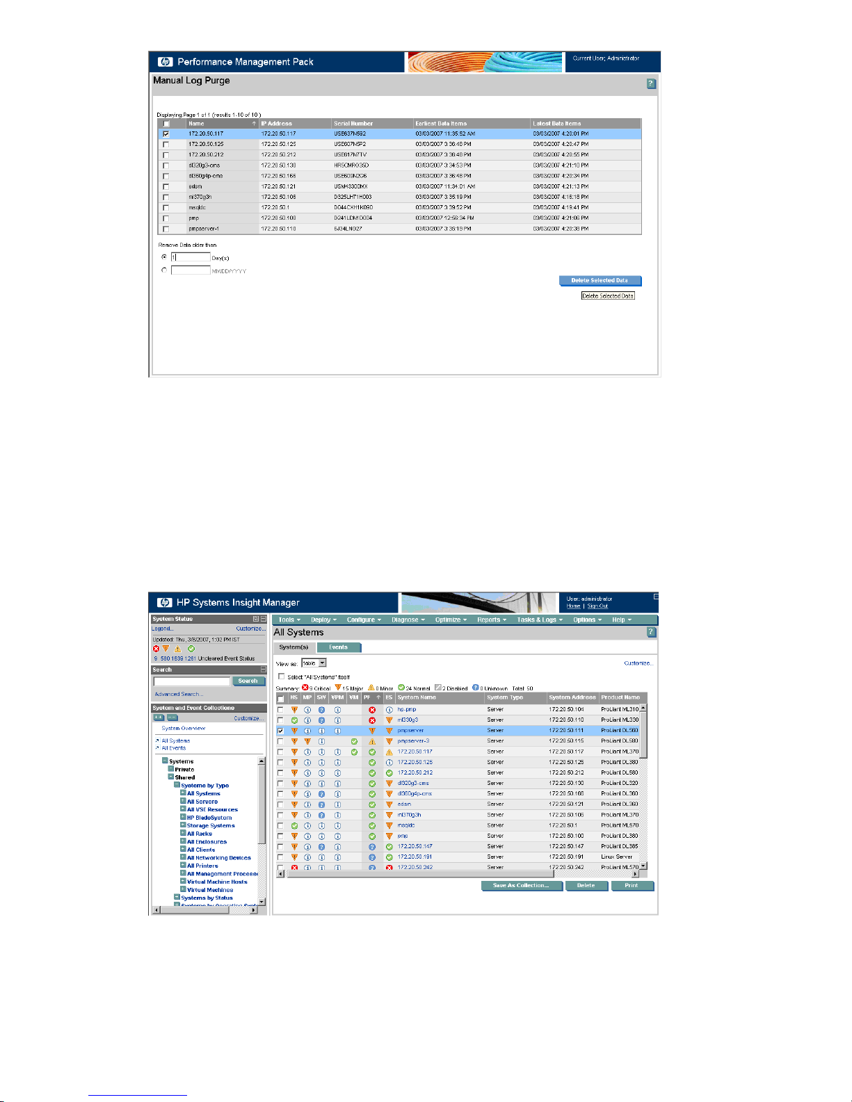
Using PMP
These sections provide an overview of PMP functionality. A usage scenario demonstrates setup, administration,
and monitoring of servers.
Opening the HP SIM console
The HP SIM console, which appears in a Microsoft Internet Explorer browser window, shows performance
status in the PF column. Icons in this column indicate the current performance state of a server.
In the following figure, an amber (Major) icon indicates a bottleneck condition exists on the server named
pmpserver. This server is referenced in the following sections.
Debugging a server bottleneck condition
The following sections discuss the appropriate actions to take when a bottleneck condition exists on a server.
In this scenario, the server name is pmpserver.
Using PMP 51
Page 52
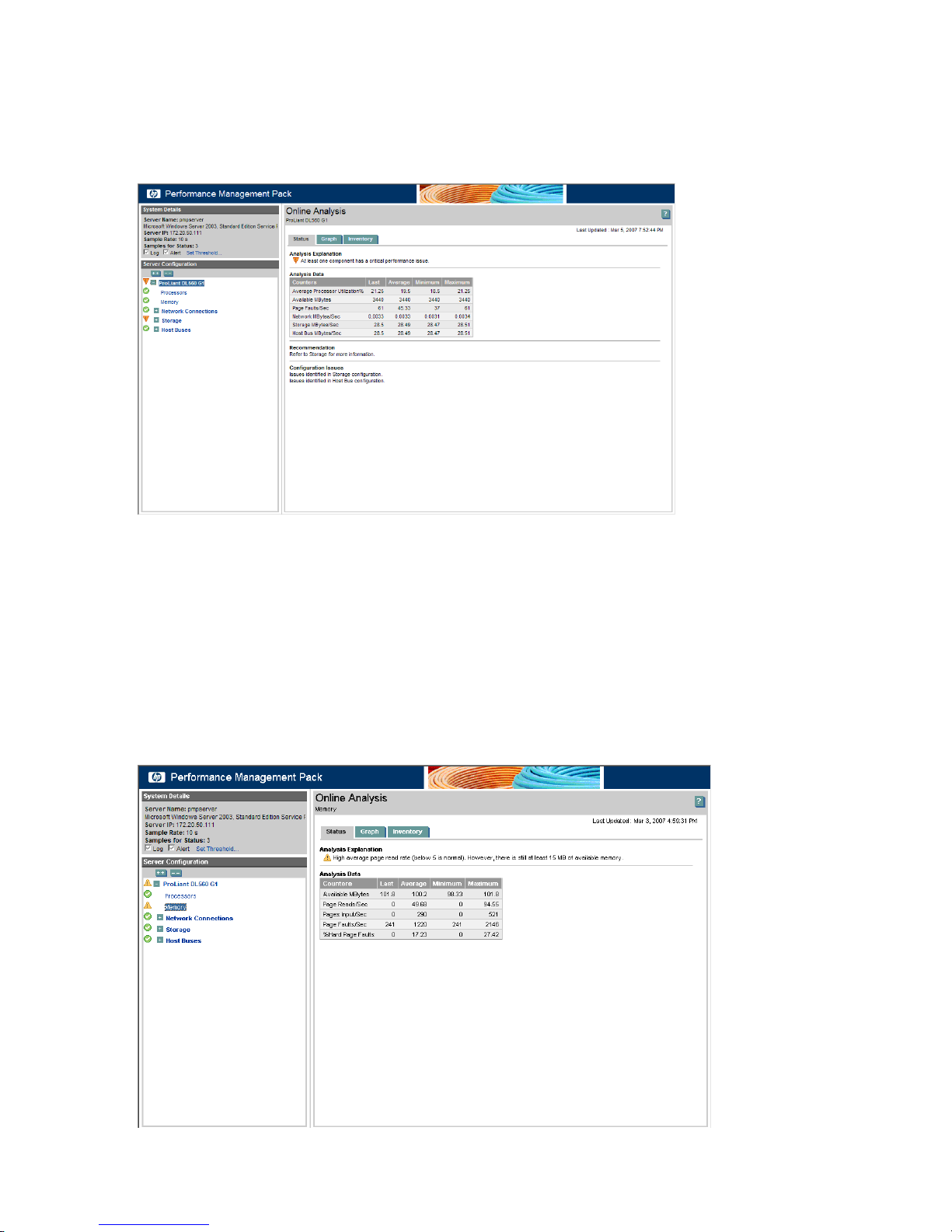
Selecting the server
To display the PMP Online Analysis window for pmpserver, click the Major icon.
The screen displays the server tree in the left navigation pane and the Status tab in the right pane. The
counters that appear in the following figure are selected items from the various components. The Analysis
Explanation indicates that at least one component has a critical performance issue.
Server problems can also be viewed in the Server Configuration pane. The tree structure in the Server
Configuration frame displays the configuration of each server, including the individual components monitored
by PMP. The icons shown in the tree next to a server or component indicate the performance status for that
item or the item under the server. The performance status icon for the selected server also appears in the
Results pane. PMP indicates multiple problems for the server in this example. Generally, only one component
has a critical performance issue because bottlenecks tend to mask one another.
Displaying the memory status
In the Server Configuration frame, to access the memory information and display the Status page for memory
in the Results frame, select Memory. Related and important memory counters appear in the Analysis Data
table.
52 Monitoring and controlling servers
Page 53
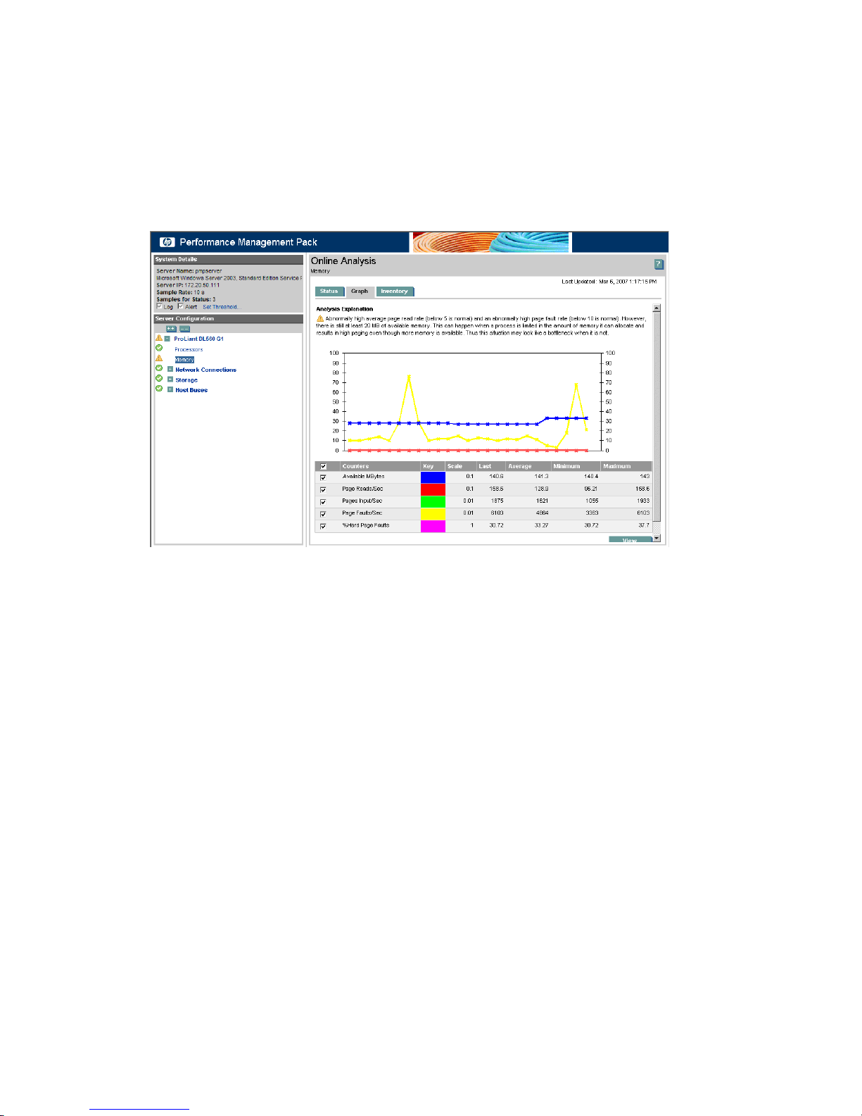
The Analysis Explanation details an above-average page-read rate (reading from the disk), and the available
physical memory is less than 15 MB. The analysis recommends more physical memory to handle the load.
Many recommendations suggest adding hardware.
In this example, the situation might have occurred because a new batch job was assigned to run on the
server at night. The remainder of this scenario examines other performance information available to assist
in troubleshooting to determine if immediate action is required to resolve the performance bottleneck.
Displaying the memory graph
To show a graphical display of memory counters in the Results pane, click the Graph tab.
This graph displays the last 25 samples taken for the server. The duration of the graph is 25 times the
sampling rate of 10 seconds, or 4.16 minutes, as shown near the upper right corner of the screen. The
graph displays what occurred on the server from 1:13 p.m. to 1:17 p.m.
The pattern of the graph shows rising, peaking, and declining, which might be caused by the completion
of the new batch job. The batch job no longer causes a problem. However, the performance information is
logged in the database for later review with the Offline Analysis tool.
Contrasting the graphical display
The following sections further demonstrate the graphical display and the full depth of analysis.
Expanding the local storage
To expand the tree structure, click the + icon next to Storage in the configuration tree, and then select the
storage node.
Contrasting the graphical display 53
Page 54
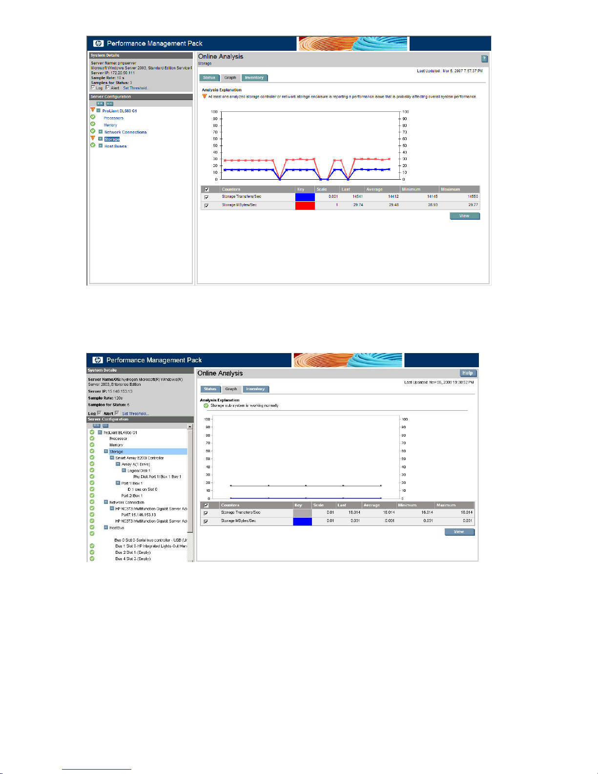
Displaying the controller
To display the tree structure for the Smart Array 5i controller, click the + icon next to SA 5i in the configuration
tree. The arrays defined for that controller and the SCSI bus entries (ports) appear.
Displaying the port
To open the tree structure for the storage system:
1. Click the + icon next to Port 1 Internal Drive Cage in the configuration tree.
2. Scroll the pane to the right to display the physical drives on that SCSI bus. Some drives have a major
icon.
54 Monitoring and controlling servers
Page 55
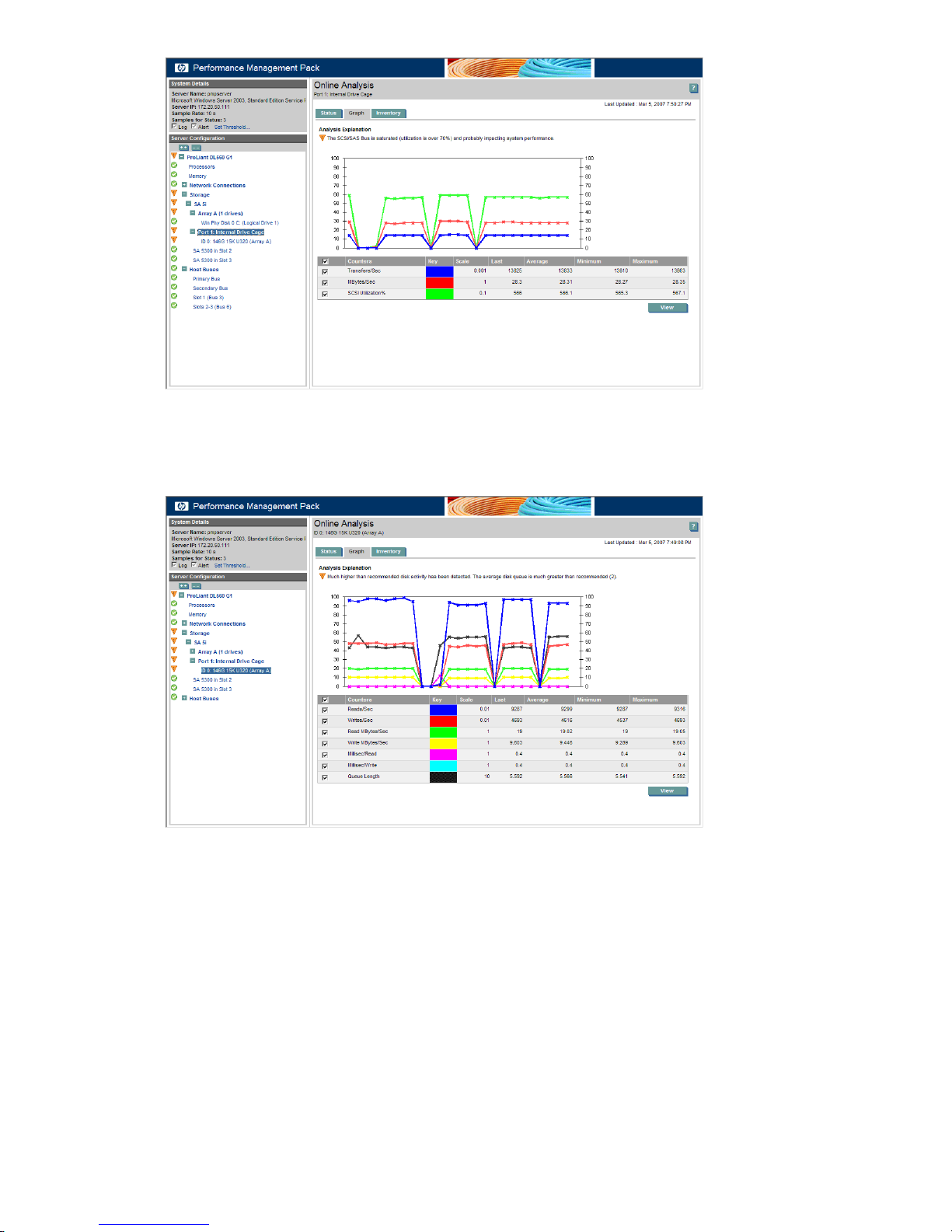
Displaying the drive
Click the ID 0: 146G 15K U320 (Array A) drive. The graph displays the performance statistics for that drive
over the last 4.16 minutes.
The graph in the previous figure trends upward to the right and levels high. These characteristics indicate
that the system is not returning to normal and might require immediate action.
Displaying the inventory
To display information for the selected drive, select the Inventory tab.
Contrasting the graphical display 55
Page 56
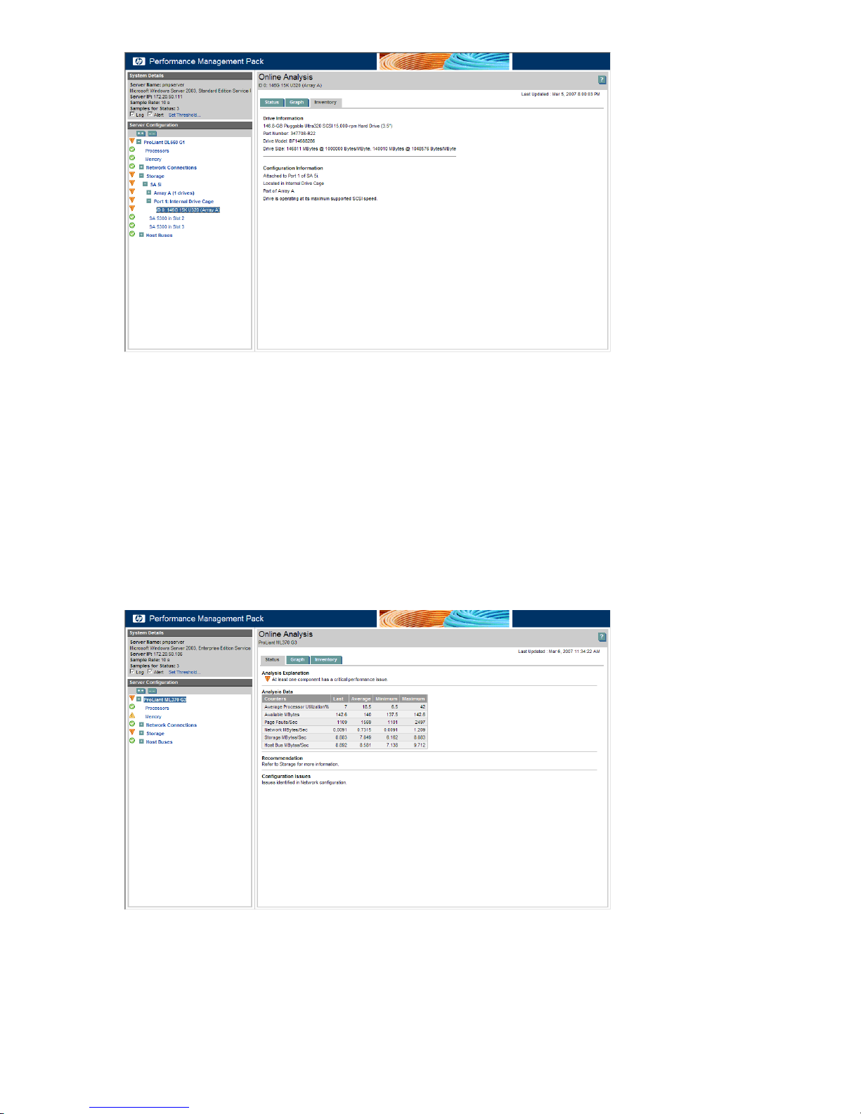
Hardware or configuration details for the currently selected device appear.
Debugging a network storage bottleneck condition
The following sections detail the appropriate responses when a bottleneck condition exists on network
storage. In this scenario, the server name is pmp-client2k, sharing network storage MSA1500cs. An amber
(Major) icon in the PF column indicates a bottleneck condition exists on the server pmp-client2k.
Selecting the server
To display the PMP Online Analysis window for pmp-client2k, click the Major icon.
The screen displays the server tree in the Server Configuration frame and the Status tab in the Results frame.
The counters that appear in the following figure are selected items from the various components. The Analysis
Explanation indicates that at least one component has a critical performance issue.
Server problems can also be seen within the Server Configuration frame. The tree structure in the Server
Configuration frame displays the configuration of each server, including individual components monitored
by PMP. The icons appearing in the tree next to a server or component indicate the performance status for
that item or the item under the server. The performance status icon for the selected server also appears in
the Results frame. PMP indicates multiple problems for the server in this example. Generally, only one
component has a critical performance issue because bottlenecks tend to mask one another.
56 Monitoring and controlling servers
Page 57
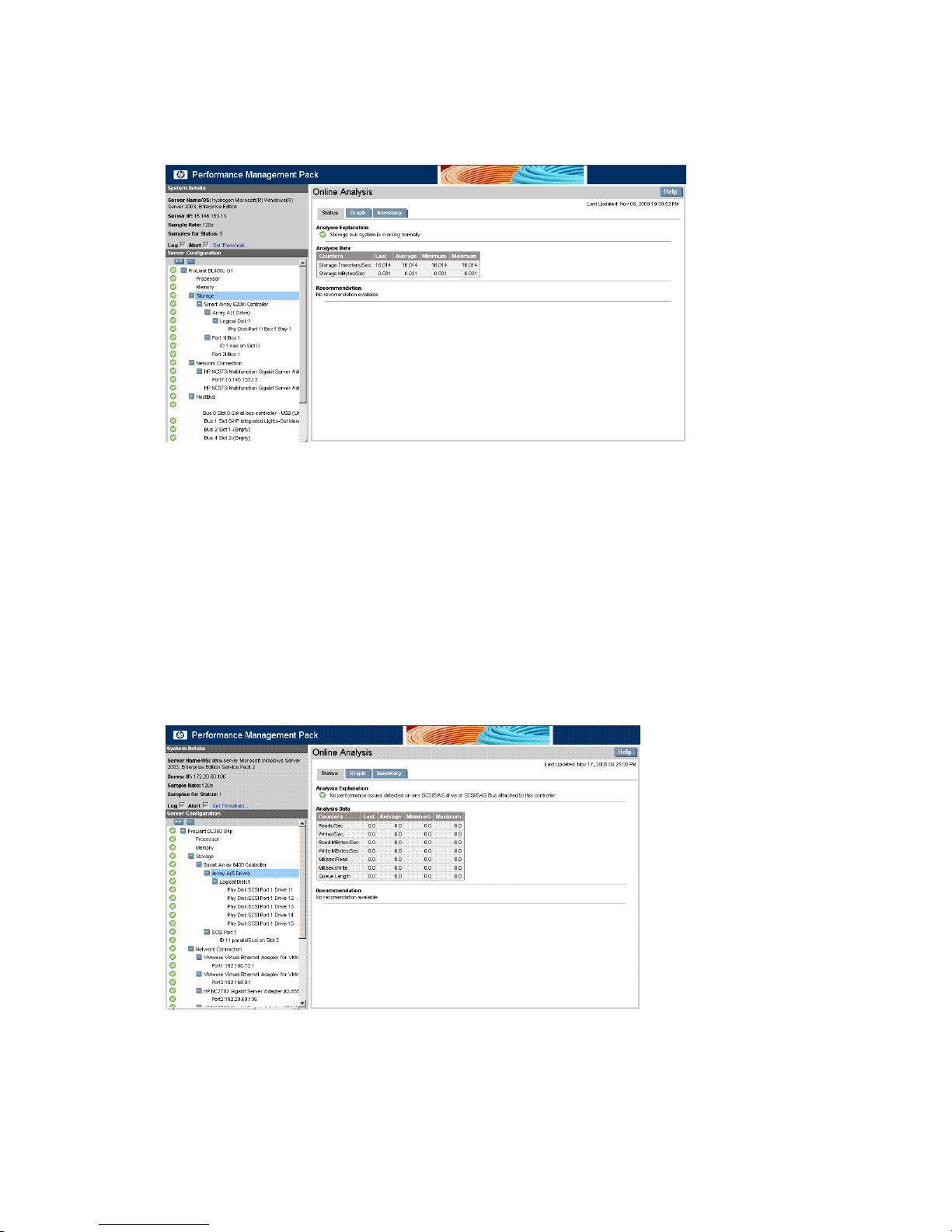
Displaying the storage status
Trace the performance issue by using the information that appears next to the amber (Major) icon.
In the Server Configuration frame, to access the storage information and display the storage status page in
the Results frame, select Storage. Related and important storage counters appear in the Analysis Data table.
The Analysis Explanation indicates that at least one storage controller or network storage enclosure is
reporting a performance issue.
The remainder of this scenario examines other performance information available to assist in troubleshooting
the critical performance issue to determine if immediate action is required to resolve the performance
bottleneck.
Displaying the logical drive under network storage
The logical drives and their performance characteristics are displayed on the left tree and by clicking on the
listed logical drive the details of the subsystems can be obtained.
Displaying the array
In the tree frame, the array information and important array counters are displayed.
Debugging a virtual machine host and guest bottleneck condition
The following sections detail the appropriate actions to take when a bottleneck condition exists on virtual
machine hosts and guests.
Contrasting the graphical display 57
Page 58
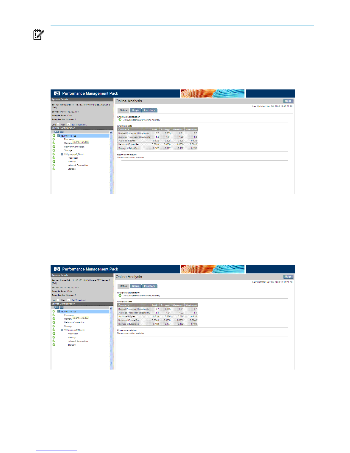
IMPORTANT: The virtual machine host must be licensed for Virtual Machine Management Pack and the
virtual machine host must be registered on the CMS before licensing and monitoring by PMP.
Selecting the server (virtual machine host)
To display the PMP Online Analysis window, click on the PF column against that node.
The screen displays the server node tree in the left configuration navigation pane and the Status tab in the
right pane. The counters that appear in the following figure are selected items from the various components.
Problems with a server can also be seen in the configuration navigation pane. The tree structure in the
configuration navigation displays the configuration of each node down to the individual components monitored
by PMP. The icons used in the tree next to a node or component indicate the performance status for that
item or the item under the node. The performance status icon for the selected node is in the Results frame.
Displaying the virtual machine host status
The virtual machine host information and display the status page for the host in the right pane. Related and
important counters for the virtual machine host appear in the Analysis Data table.
The Analysis Explanation indicates that the virtual machine host includes the performance of the virtual
machine guests.
The remainder of this example examines other performance information available to assist in making a
judgment regarding the problem and determines if immediate action is required to resolve the performance
bottleneck.
58 Monitoring and controlling servers
Page 59
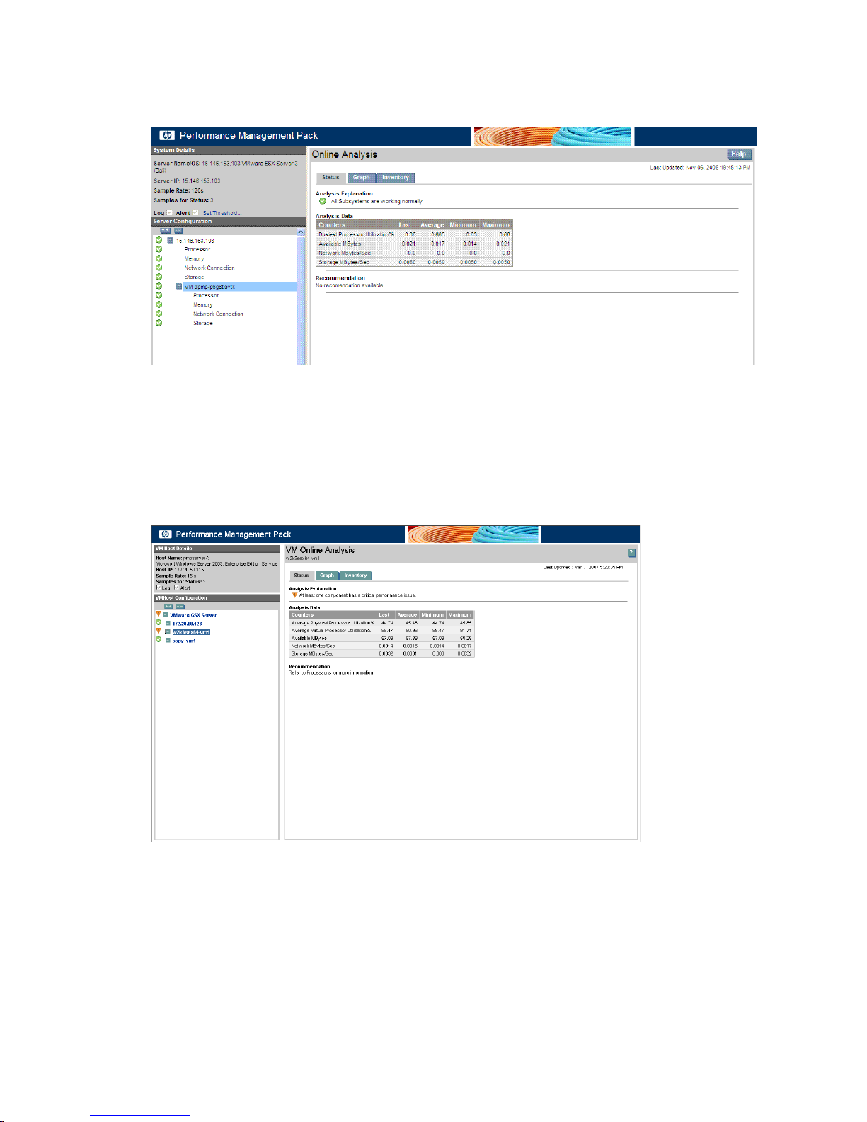
Displaying the virtual machine guests page
From the navigation tree, to access the virtual machine guests that will list the guest that are monitored by
PMP.
In this example, the Analysis Explanation indicates that this virtual machine host is experiencing a performance
issue.
Displaying the virtual machine guest
From the navigation tree, to access the virtual machine guest and display the status page in the right panel,
click the associated virtual machine guests tree. Related and important counters for the virtual machine guest
appear in the Analysis Data table.
In this example, the Analysis Explanation indicates that at least one component has a critical performance
issue.
Displaying the virtual machine guest performance
From the navigation tree, click on the respective VM guest subcomponents to get the performance parameters
for the VM guest components being monitored by PMP.
Contrasting the graphical display 59
Page 60
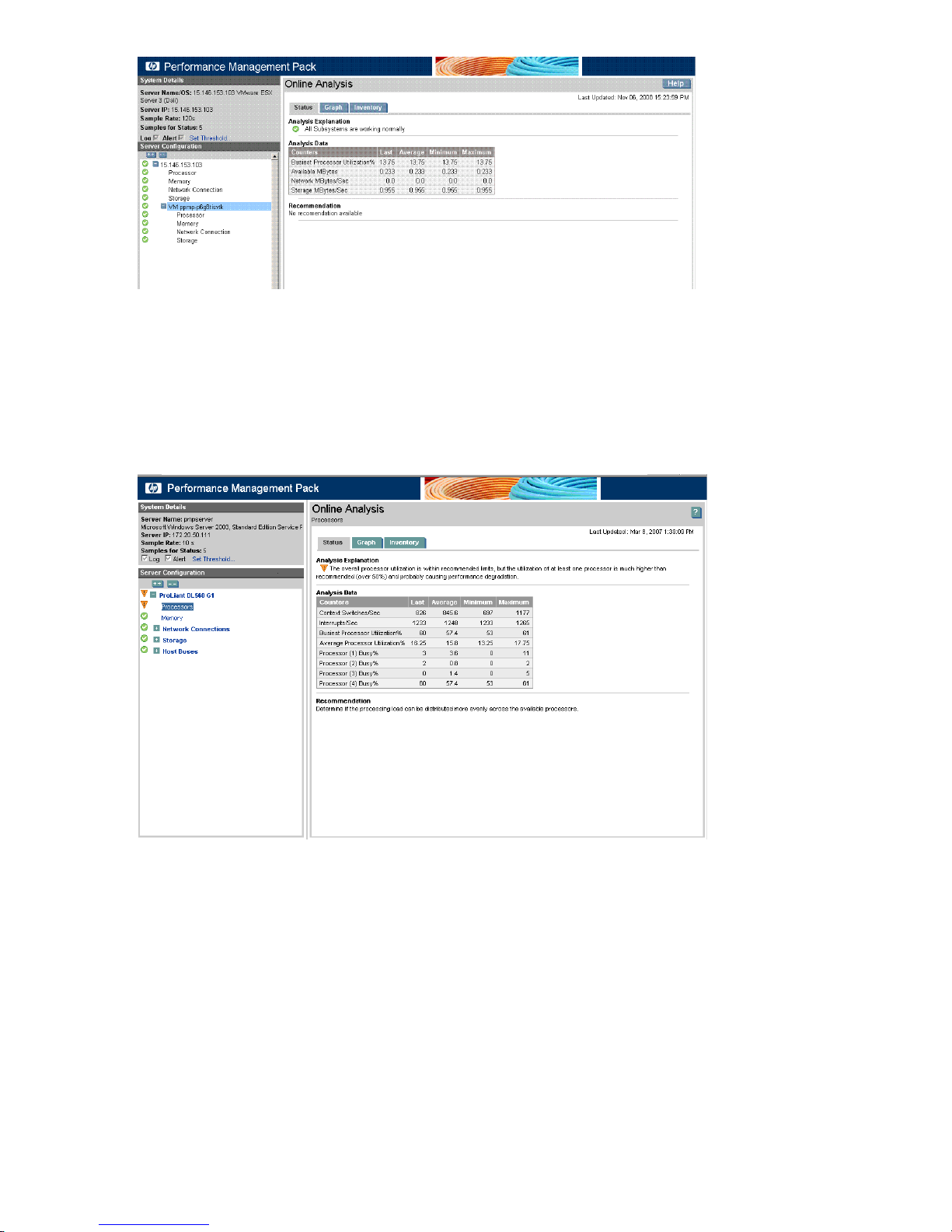
In this example, the Analysis Explanation indicates that processor utilization is extremely high (over 90%)
and probably causing performance degradation.
Addressing performance issues with no hardware upgrade recommendation
The following scenario provides an example of a recommendation that does not suggest additional hardware.
In the following figure, a major status icon appears for the processors. Online Analysis recommends that
you determine if the processing load can be distributed more evenly across the available processors.
This recommendation indicates that more than one logical processor exists in the system and at least one
processor is not fully utilized. This recommendation demonstrates not only a solution without involving
hardware, but also the specificity of PMP. Online Analysis recommendations for these types of performance
issues are component-specific.
Performing a static analysis
The following sections provide examples of using static analysis.
General usage
Performance issues are often introduced during system configuration. This condition might be caused by a
planning error, an error in following the prescribed configuration path, or as a result of the system receiving
many updates to a system over time. Regardless of the cause, PMP can analyze static configurations and
make suggestions about areas of concern before a change occurs.
To see a static analysis report:
60 Monitoring and controlling servers
Page 61
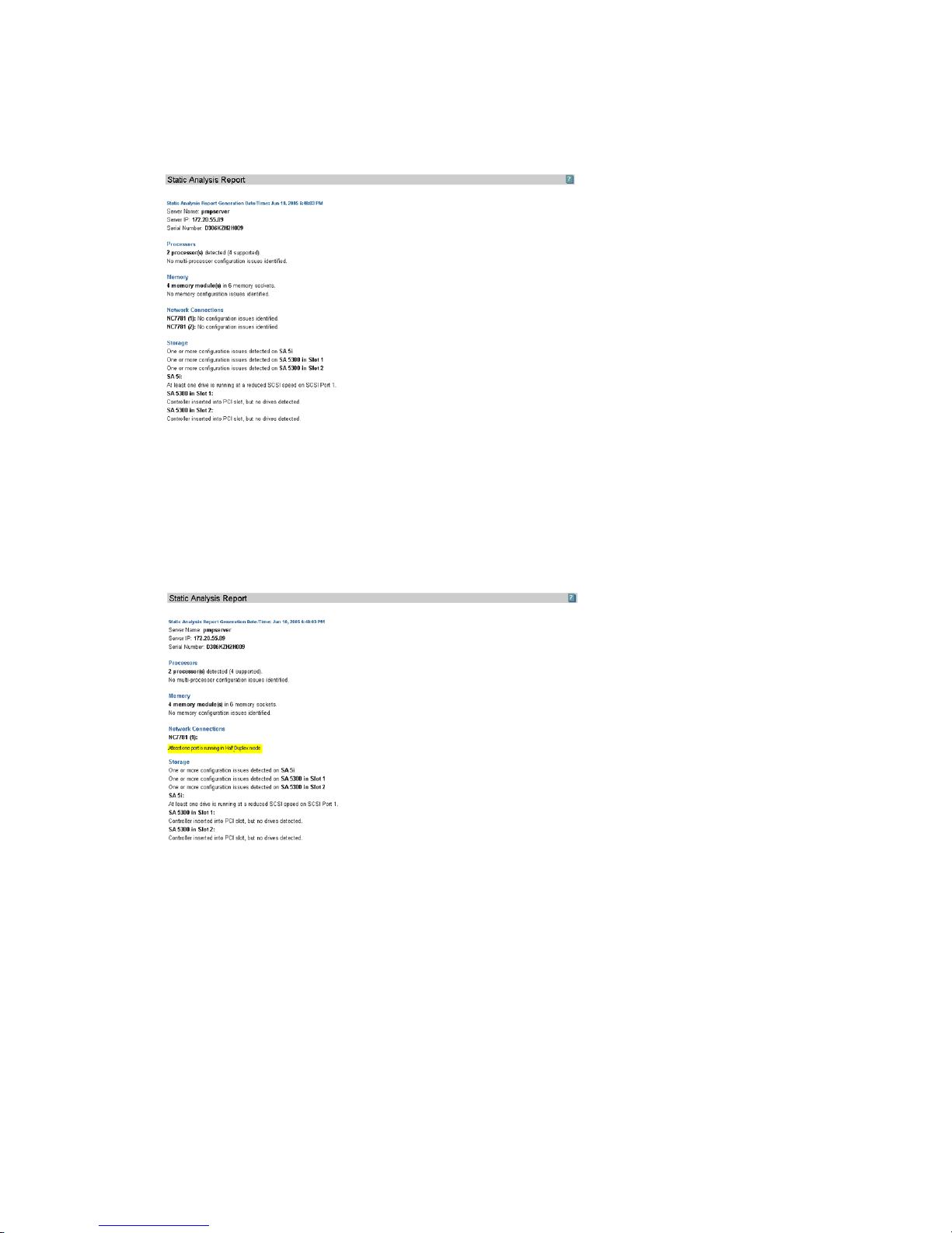
1. From the Systems Insight Manager console toolbar, click Reports→Performance Management Pack
Reports→Static Analysis Report.
2. Select the pmpserver checkbox.
3. To display the Static Analysis Report for pmpserver, click Generate Report. These results can be printed
from the browser.
Half duplex port
Review the report shown in the following figure.
The report shows the first potential issue, indicated by the At least one port is running in Half
Duplex mode message. PMP indicates that a network port is running in half-duplex mode, which can cause
a bottleneck. In this case, half duplex was set in error, and that setting is causing an artificial bottleneck for
network traffic over that port.
Unassigned disks
The next message in the report that might indicate a problem is One or more physical disks are
not assigned to an array. In many cases, this condition can be expected, particularly if online spare
drives are configured because they are not part of an array set. However, this condition might be unexpected
if there is an interrupted array configuration attempt.
Contrasting the graphical display 61
Page 62
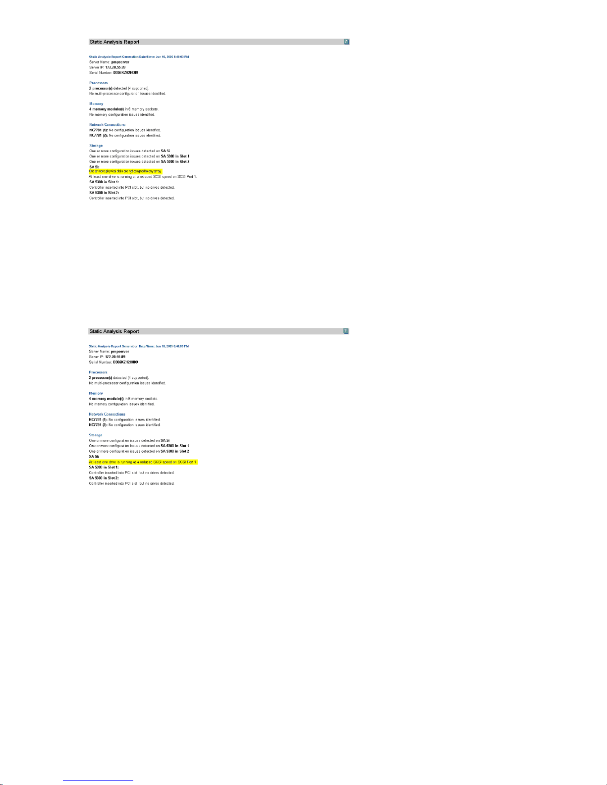
Reduced SCSI speed
The next message in the report that might indicate a problem is At least one drive is running
at a reduced SCSI speed on SCSI Port 1. In this example, the HP ProLiant DL380 server was
configured correctly with a new Smart Array controller and Ultra320 drives, but the drives are not running
at Ultra320 speed. Further examination of the hardware might reveal an older SCSI cable as a potential
problem. Testing might reveal that the differential pin on the SCSI cable is bad, causing the drive and
controller to revert to SCSI-2 speed for transmission. PMP detects the potential performance problem and
helps narrow the cause before any product work is done on the server.
Host bus balancing
Although no error messages appear in this static analysis, PMP can determine how the devices in a system
are laid out across the host buses and what issues might arise from bus overloading.
Performing Online Analysis
The PMP Online Analysis tool enables performance data to be viewed from a real-time data stream and
provides an intuitive interface to detail the performance status and inventory of monitored servers and their
components.
Online Analysis is used to determine that the system required more physical memory to handle the assigned
load balance.
To use Online Analysis, choose either of the following options:
1. From the Systems Insight Manager PF column, click the monitored server icon.
2. Perform the following steps:
62 Monitoring and controlling servers
Page 63

a. From the Systems Insight Manager console toolbar, click Diagnose→Performance Management
Pack→Online Analysis.
b. Select the checkbox next to the server or servers for which to view performance data. The checkbox
at the top of the column can be used to select all of the servers listed on the page.
c. Click Apply Selections→Run Now. Online Analysis appears in a new window.
When Online Analysis is started for a server, an Online Analysis session is started automatically for any
network storage enclosure connected to that server.
PMP supports all Hypervisors supported by HP Virtual Machine Management Pack.
If you have hypervisor installed, and you have configured Virtual Machines, PMP treats this server as a VM
host. When PMP identifies the server as a VM host, you must license the server through Virtual Machine
Management Pack. When the VM host is licensed through Virtual Machine Management Pack, PMP collects
performance data of the host. PMP displays the information provided by VMM.
Clicking on
lists the VM Guests being monitored.
Performing Offline Analysis
The Offline Analysis tool enables performance data to be viewed from a database that has been captured
and logged over a specified time. This tool enables manipulation of the rate at which data is played back
for analysis by speeding or slowing the refresh rate or selecting specific points in the presentation of previously
captured events without regard to chronology.
In the previous example, it was determined that the system required more physical memory to handle the
assigned load balance. Offline Analysis enables examination and analysis of precisely what occurred on
pmpserver between 3:01 to 3:37 P.M. when a problem occurred.
The Offline Analysis tool enables you to view recorded data sessions from the PMP database.
To use Offline Analysis:
1. From the Systems Insight Manager console toolbar, click Diagnose→Performance Management
Pack→Offline Analysis.
2. Select the checkbox next to the server or servers for which to view performance data. The checkbox at
the top of the column can be used to select all of the servers listed on the page.
3. Click Apply Selections→Run Now.
4. Select the start date and refresh rate for which to display performance data. The refresh rate determines
the rate at which the logged data is played back.
5. Click Start Offline Analysis.
After selecting offline analysis parameters, the session appears as illustrated in the following figure. For
information about navigation tools and the tabs provided with this interface, see the Using PMP section in
this guide.
The following icons are provided for bottleneck navigation:
Contrasting the graphical display 63
Page 64
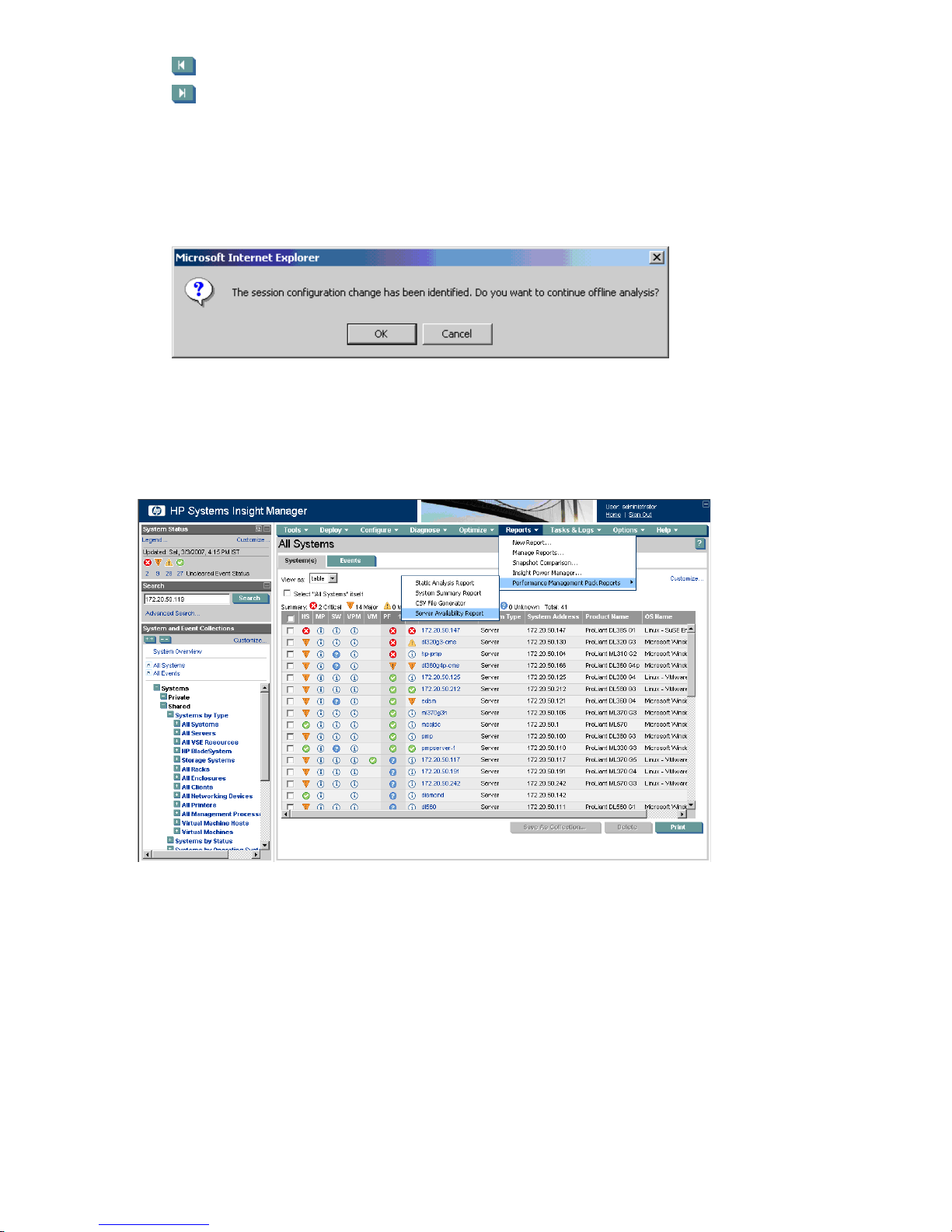
1. back to the previous bottleneck
2. forward to the next bottleneck
3. For example, if a status change happens at 6:00 a.m. from green to amber, yellow to amber, or green
to yellow, click the Next or Previous bottleneck navigation button and the Offline Analysis page for
6:00 a.m. appears. However, if the status changes at 6:00 a.m. from amber to yellow, amber to green,
or yellow to green, the next bottleneck button does not navigate to that time.
PMP Offline Analysis can detect hardware configuration changes. A message appears when a
configuration change is identified, as shown in the following figure.
Data reporting
Because PMP can be configured to store all performance data measurements that are analyzed, stored data
can be converted to reports. Reports are generated from HP SIM. The report, when generated for a specific
server, provides a summary of the performance statistics for the time period selected.
To generate a report:
1. Select Reports→Performance Management Pack Reports.
2. Click the format in which to generate the report. Available formats are:
a. Static Analysis Report
b. System Summary Report
c. CSV File Generator
d. Server Availability Report
For a description of these report types, see the following sections.
64 Monitoring and controlling servers
Page 65
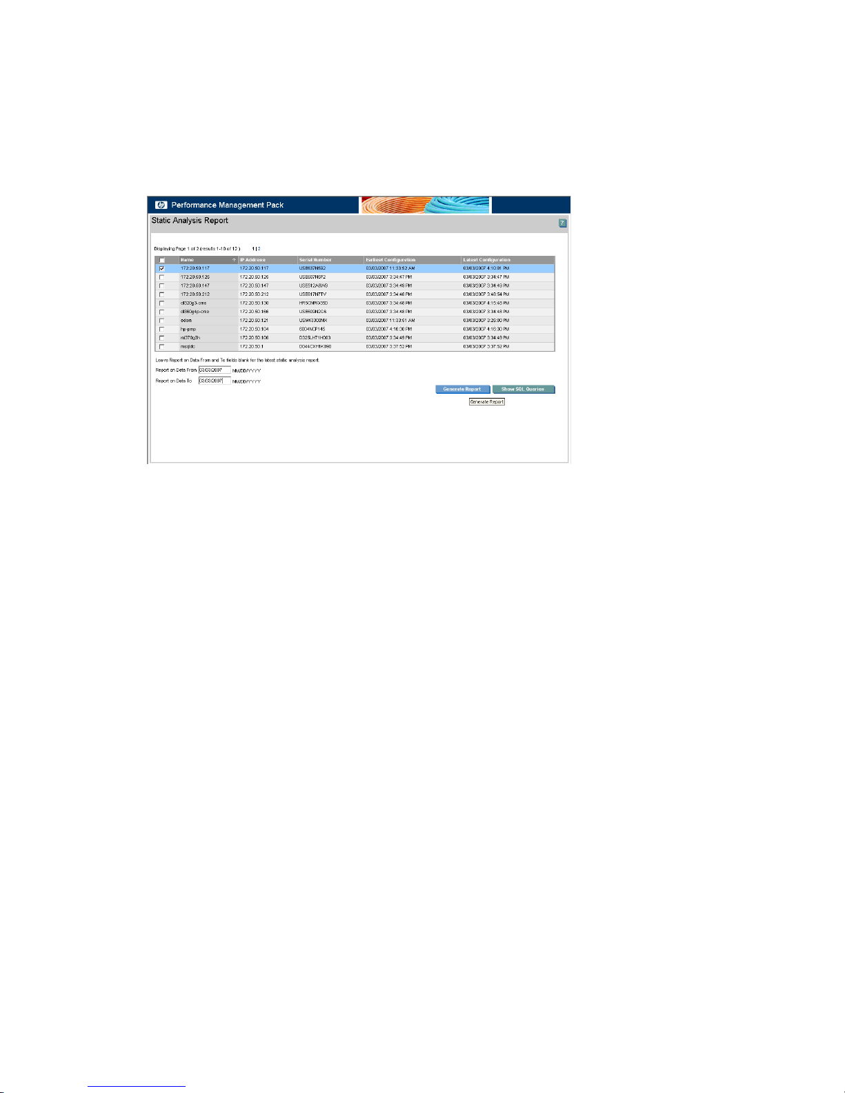
Generating a Static Analysis Report
1. When a separate browser window appears listing the selected servers, select the server for which you
want to generate a report.
2. Enter the appropriate dates in the Report on Data From and Report on Data To boxes to get the period
for which you want to generate the report. Leave these boxes blank to generate a report from the current
performance data.
3. Click Generate Report. The report appears in a separate browser window.
Generating a SQL queries list
1. From the Static Analysis Report screen, select the server for which you want to generate a list.
2. Enter the appropriate dates in the Report on Data From and Report on Data To boxes to get the period
for which you want to generate the list. Leave these boxes blank to generate a list from the current
performance data.
3. Click Show SQL queries. The SQL query appears in a separate browser window. The static analysis
report is not available for VM guests.
Generating a System Summary Report
1. When a separate browser window appears listing the selected servers, select the server for which you
want to generate a report.
2. Enter the appropriate dates in the Report on Data From and Report on Data To boxes to get the period
for which you want to generate the report.
3. Enter an appropriate file name with an .htm extension in the File Name box.
4. Click Generate Report. The report appears in a separate browser window.
Contrasting the graphical display 65
Page 66
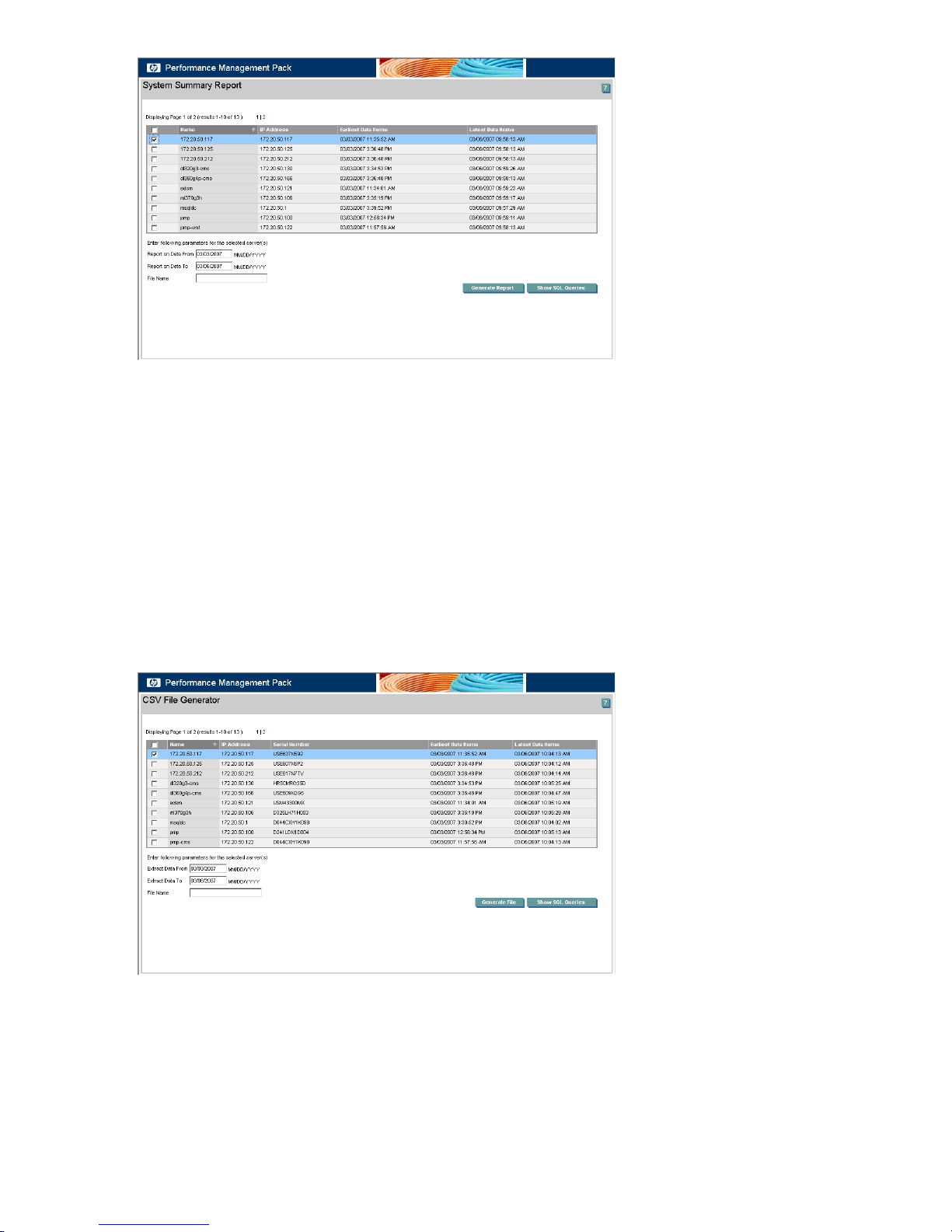
Generating a SQL queries list
1. From the System Summary Report screen, select the server for which you want to generate a list.
2. Enter the appropriate dates in the Report on Data From and Report on Data To boxes to get the period
for which you want to generate the list.
3. Click Show SQL queries. The SQL query appears in a separate browser window.
Generating a CSV File Generator Report
1. When a separate browser window appears listing the selected servers, select the server for which you
want to generate a report.
2. Enter the appropriate dates in the Extract Data From and Extract Data To boxes to get the period for
which you want to generate the report.
3. Enter an appropriate file name with a .csv extension in the File Name box.
4. Click Generate File. The report appears in a separate browser window.
Generating a SQL queries list
1. From the CSV File Generator screen, select the server for which you want to generate a list.
2. Enter the appropriate dates in the Extract Data From and Extract Data To boxes to get the period for
which you want to generate the list.
3. Click Show SQL queries. The SQL query appears in a separate browser window.
66 Monitoring and controlling servers
Page 67
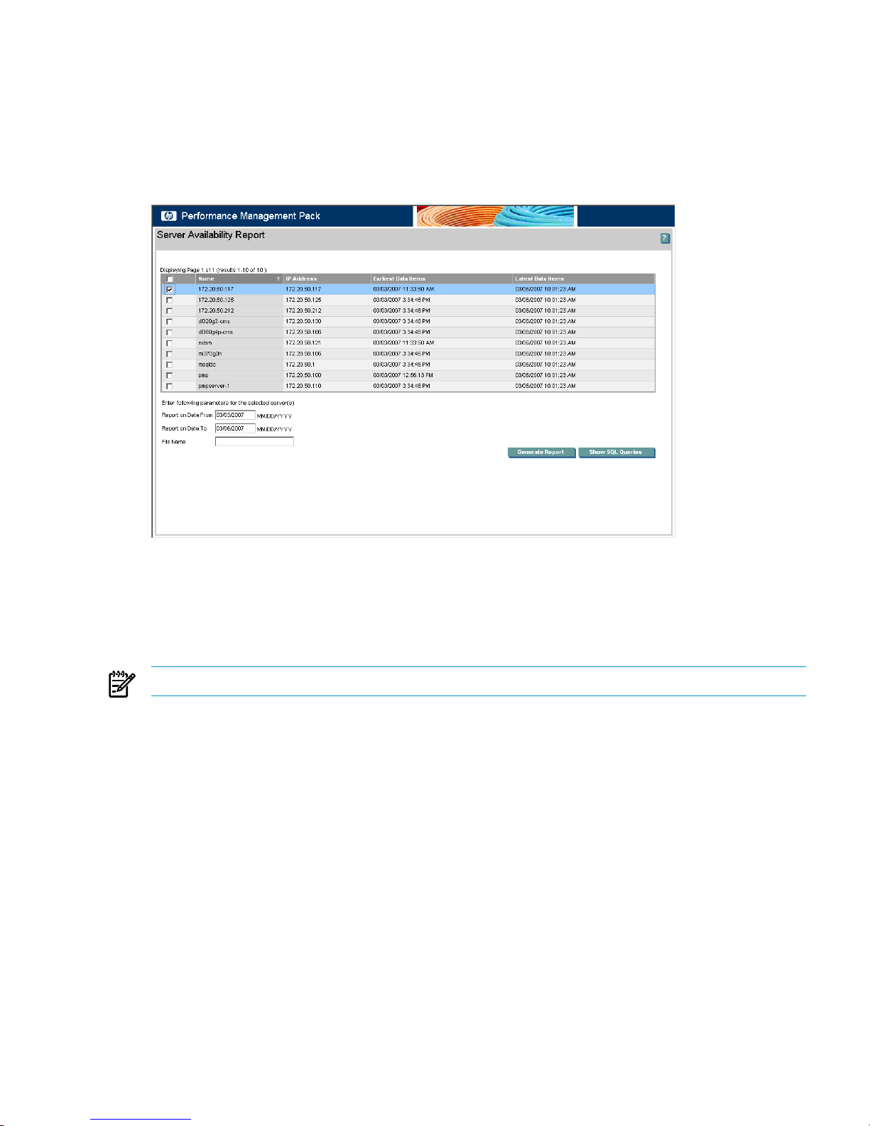
Generating a Server Availability Report
1. When a separate browser window appears listing the selected servers, select the server for which you
want to generate a report.
2. Enter the appropriate dates in the Report on Data From and Report on Data To boxes to specify
the period from which to generate the report.
3. Enter an appropriate file name with an .htm extension in the File Name box.
4. Click Generate Report. The report appears in a separate browser window.
Generating a SQL queries list
1. From the Server Availability Report screen, select the server for which to generate a list.
2. Enter the appropriate dates in the Report on Data From and Report on Data To boxes to specify
the period from which to generate the list.
3. Click Show SQL Queries. The SQL query appears in a separate browser window.
NOTE: Server availability reports are not available for virtual machine guests.
Licensing Integrity and Storage Systems
You do not need a license for monitoring Integrity and storage systems.
Licensing virtual machine hosts and virtual machine guests
The procedure to license virtual machine hosts is not the same as the procedure to license other servers.
However, as a prerequisite, the virtual machine host must be licensed in Virtual Machine Management Pack.
The VM Host cannot be licensed for PMP if it is not licensed in Virtual Machine Management Pack.
Contrasting the graphical display 67
Page 68
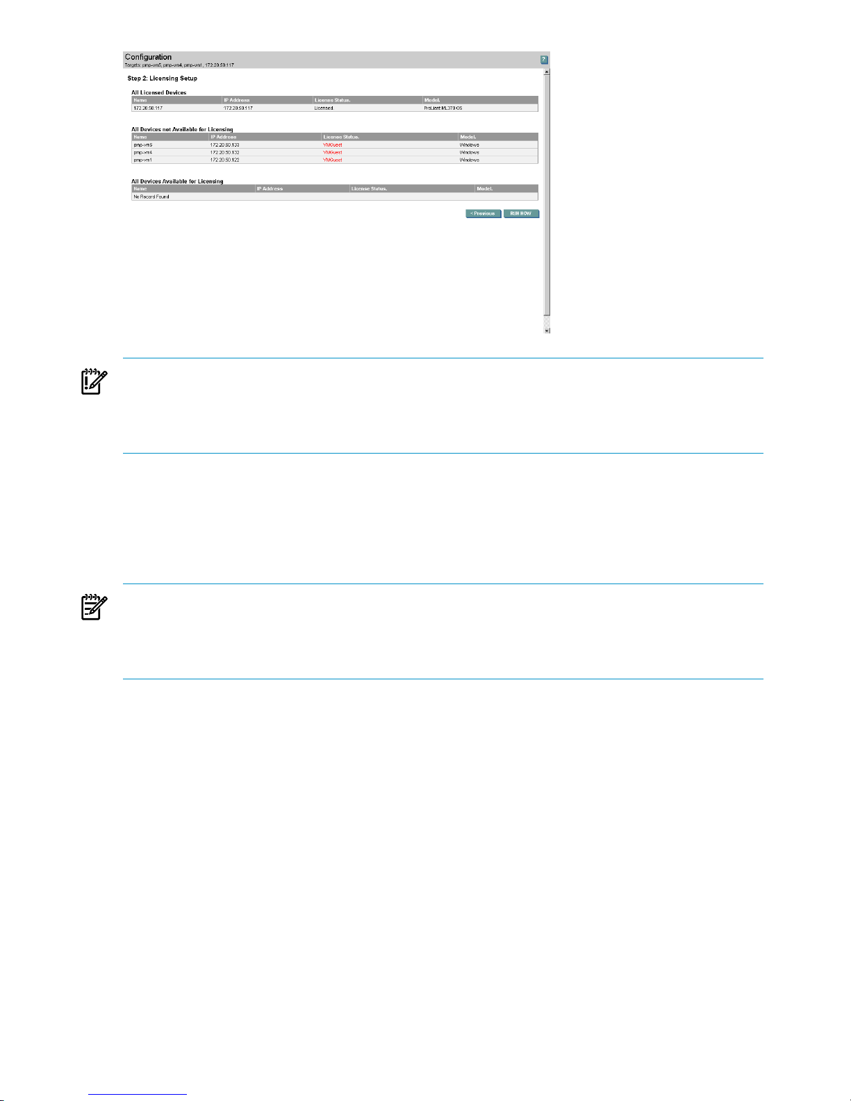
IMPORTANT: If you license a server for PMP and then convert that server to a virtual machine host, you
are not required to license the virtual machine host again for PMP. However, this virtual machine host must
be licensed for Virtual Machine Management Pack. The virtual machine host can be monitored only when
licensed by Virtual Machine Management Pack. Similarly, if a virtual machine host is converted to a physical
server, it is not expected to be licensed again for PMP.
For more information about licensing Virtual Machine Management Pack, see the Virtual Machine Management
Pack documentation.
Monitoring administration
Servers are monitored based on monitoring parameters. The monitoring status and the number of samples
are set in PMP for servers and storage enclosures that you want to monitor.
NOTE: The Update Server List populates the status of servers that have changed and synchronizes the data
from HP SIM. The Refresh button on the MA page is to get the updated information as systems are being
discovered in PMP and the required data being collected from these systems. The list of systems for which
the data collection is underway are greyed out and once the complete configuration information is collected
the systems are selectable in the MA page.
Changing server monitoring status
Servers that are licensed for monitoring appear on the Monitoring Administration page. Servers that are
currently being monitored by PMP appear with Started as the value in the Monitor Status column. Servers
that are not currently being monitored have no value in the Monitor Status column. The default values for
monitoring status and number of samples are listed beside each server.
68 Monitoring and controlling servers
Page 69
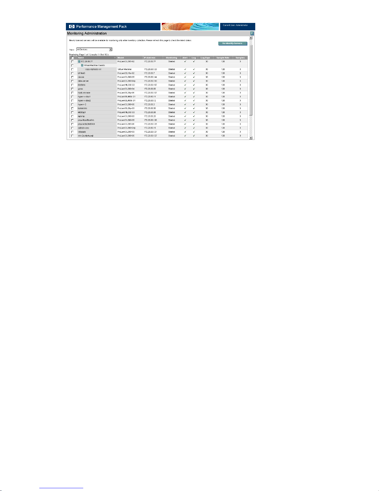
The server list that appears on the Monitoring Administration page can be filtered to display all devices, all
monitoring devices, all devices available for monitoring, all alerting devices, all devices available for alerting,
all logging devices, or all devices available for logging. Select the appropriate filter from the View list box.
Use the page links that appear when there are multiple pages to navigate between pages.
The view filter is not applicable for VM Guests. The VM Guest does not appear for the All devices available
for monitoring filter, even though it is not marked for monitoring when the host is being monitored. The VM
Guest only appears in the list depending on the VM Host status. If the VM Host is not marked for monitoring,
then all associated VM Guests appear in this list. Similar conditions apply for Alert and log. Monitoring of
VM Guests is stopped if the associated VM Host is stopped for monitoring.
To change the monitoring status for a particular server:
1. From the Systems Insight Manager console toolbar, select Options→Performance Management Pack
Options→Configuration.
2. Click the Server tab. Servers available for monitoring appear in the list.
3. Identify the server for which you want to change monitoring parameters from the server list, and then
select or clear the box next to the server. The checkbox at the top of the column can be used to select
or clear all servers listed on the page.
4. Select or clear the monitoring parameters (Monitor/Alert/Log) for the server, and then select the number
of samples to use to determine status from the list.
5. Click Apply. The changes made to the monitoring status of the server are updated.
6. Selected servers begin a new monitoring session with the updated parameters, terminating any current
monitoring session.
Enabling virtual machine host and virtual machine guests logging
Virtual machine guests that are configured on the virtual machine host currently being monitored are not
automatically monitored. These virtual machine guests appear on the Monitoring Administration page with
a checkbox and can either be selected individually or collectively using the Virtual Machine Guests checkbox.
Contrasting the graphical display 69
Page 70
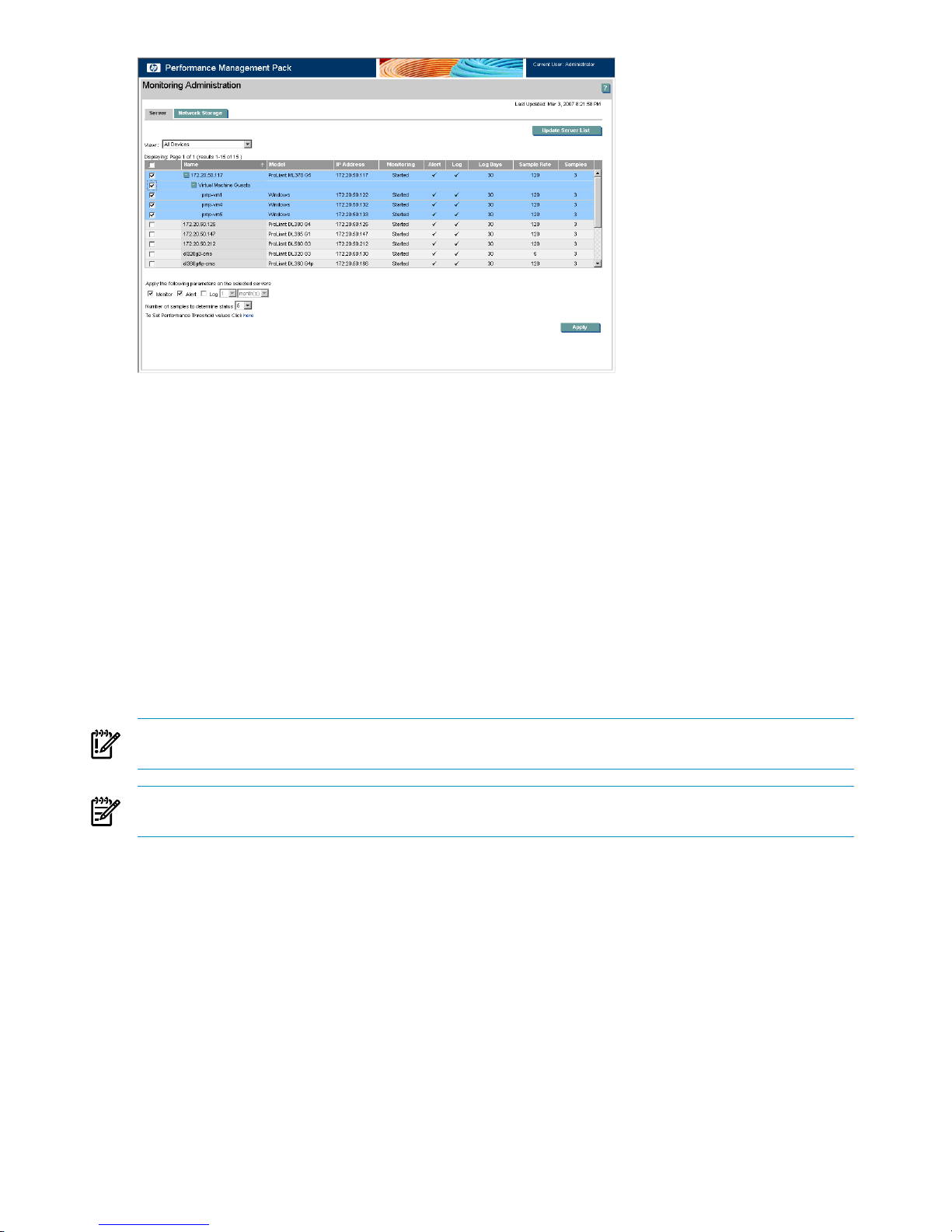
To enable logging for virtual machine guests:
1. From the HP SIM console toolbar, select Options→Performance Management Pack
Options→Configuration. The Monitoring Administration page appears in a new window.
2. Select the Server tab. Servers or virtual machine hosts and virtual machine guests available for
monitoring appear in the list.
3. Select the virtual machine guest for which to change monitoring parameters. To select all the items listed
on the page, select the checkbox at the top of the column.
4. Select the monitoring parameters (Monitor, Alert, and Log) for the virtual machine guests.
5. Click Apply. The changes made to the monitoring status of the server are updated.
Selected virtual machine guests begin a new monitoring session with the updated parameters and terminate
any current monitoring session.
Data for virtual machine hosts and virtual machine guests is only logged to the PMP database after logging
is selected and parameters are applied. Logging of virtual machine guests is not independent of the connected
virtual machine hosts. For example, data cannot be logged for a virtual machine guest if not also logged
for the connected virtual machine host.
IMPORTANT: To monitor, alert, and log virtual machine guests, enable the monitor, alert, and log parameters
for the associated virtual machine host.
NOTE: The sample rate, log days, and number of samples cannot be set for the virtual machine guests.
These values are the same as those of the virtual machine host.
Monitoring parameters
PMP monitoring can operate in four modes:
1. Monitor - This mode enables server status monitoring, updating information that HP SIM and PMP
display. Analysis information and debug performance issues can be viewed using the Online Analysis
tool.
2. Monitor & Alert - This mode, in addition to the capabilities enabled with Monitor, sends alerts to HP SIM
when the status of a server changes.
3. Monitor, Log, & Alert - This mode, in addition to the capabilities enabled with Monitor & Alert, stores
detailed performance information in the PMP database for later reporting or playback, using the Offline
Analysis tool.
4. Monitor & Log - This mode enables monitoring of servers and stores the performance information in the
PMP database for playback later.
When monitoring begins for a server, the alert and log status in the table reflect that the Alert and Log options
are chosen. When the monitoring ends, the table shows the previous state of Alert and Log status. The
following figure illustrates the details.
70 Monitoring and controlling servers
Page 71

1. Row number 1: Monitoring is started, Alert and Log enabled. The results are Started, Tick and Tick in
the table.
2. Row number 2: Monitoring, Alert and Log disabled. The results are Blank, Tick and Tick in the table
reflecting the previous state of Alert and Log when the monitoring is stopped.
3. Row number 6: Monitoring is started, Alert enabled and Log disabled. The results are Started, Tick and
Blank reflecting the current status whenever the monitoring is started.
4. Row number 7: Monitoring, Alert and Log disabled. The results are Blank, Tick and Blank reflecting the
previous state of the Alert and Log when the monitoring is stopped.
Number of samples
The Number of samples setting enables adjustment of PMP analysis to account for highly variable or stable
system performance. A higher number of samples results in smaller average changes in performance.
Therefore, it generates fewer performance bottleneck indications for a server whose performance changes
significantly. Fewer samples can be used for servers with more stable performance or when the sampling
rate is higher.
Performance threshold setting
The hyperlink To Set Performance Threshold values click here enables setting the performance threshold
values for the selected server in a separate page.
Modifying the sample rate
PMP does not control the amount of time between samples. Instead, the sample rate (data collection interval)
is set from within the HP Management Agents. The Management Agents can be modified from the Control
Panel or Internet Explorer.
The sample rate for a network storage enclosure is determined by the servers to which the enclosure is
connected. The sample rate for storage enclosures is the highest sample rate of the connected servers.
Modifying log days
The log days option enables you to choose the number of days for which you need data logged. You can
select a value for this option using the two lists. The first list contains values from 1 through 20. The second
list has options such as days, months, and years. For example, if you select 2 in the first list and Years in
the second list, data is logged for 730 days. The data that was logged first is replaced cyclically as new
data is logged.
Modifying Management Agents from the Control Panel
1. From the Control Panel, open HP Management Agents.
2. Click the SNMP Settings tab.
3. Modify the Data Collection Interval (sample rate) as necessary.
Contrasting the graphical display 71
Page 72
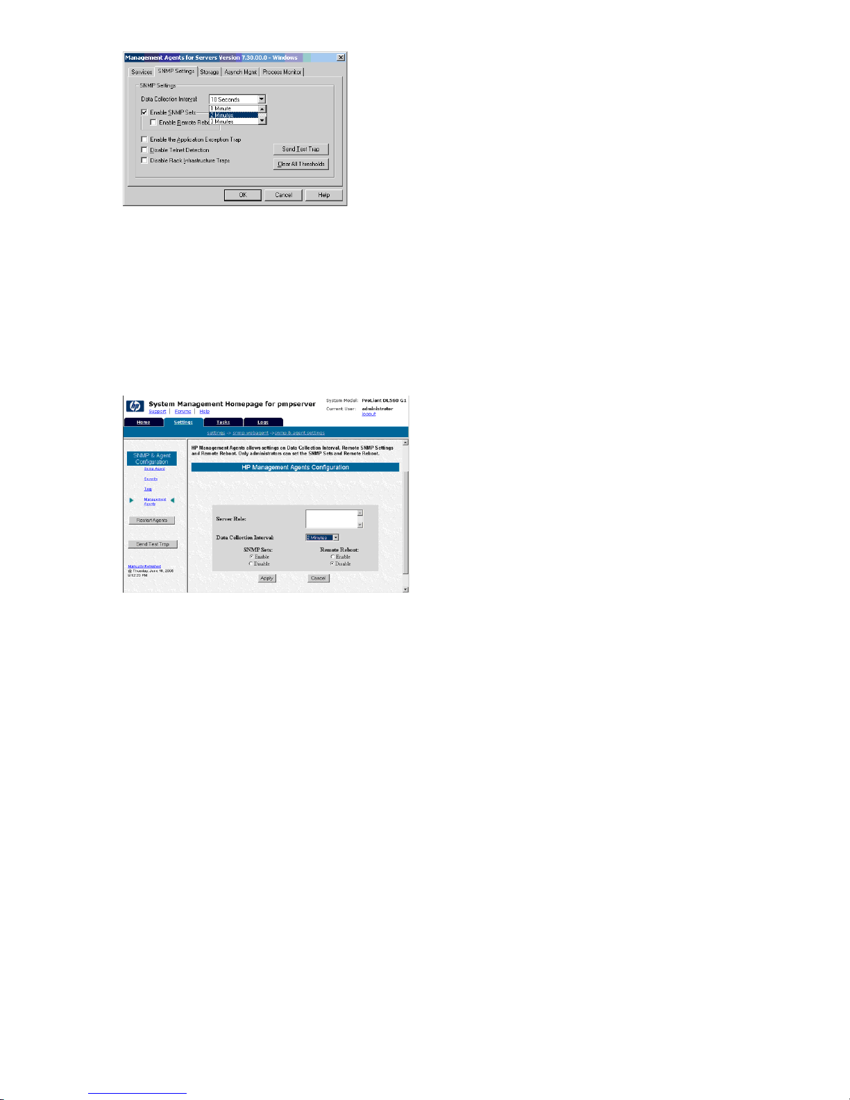
Modifying Management Agents from Internet Explorer
1. Browse to the server where you have installed the Management Agents (for example,
http://servername:2301/, where servername is the name of your server and 2301 is the active port).
2. Log in as an administrator.
3. Click the Settings tab.
4. Click SNMP Configuration→Management Agents.
5. Modify the Data Collection Interval (sample rate) as necessary, and then click Apply.
6. After the sample rate is changed, restart the Management Agents.
Setting performance thresholds
The Set Performance Threshold option enables you to set performance threshold values for processor, memory,
NIC, storage, and PCI subsystems of the servers.
You can set performance by navigating through any of the following options:
1. HP SIM menu
2. Monitoring Administration page
3. Online Analysis page
To set thresholds using the HP SIM menu:
1. From the HP SIM menu, select Options→Performance Management Pack Options→Set
Performance Threshold.
2. Select the servers for which to set thresholds. Thresholds cannot be set for the network storage and
virtual machine guests.
3. To set thresholds, click Apply.
72 Monitoring and controlling servers
Page 73
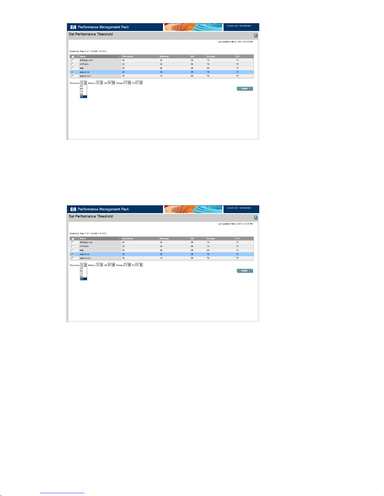
To set thresholds from the Monitoring Administration page:
1. From the Monitoring Administration page, click the To Set Performance Threshold values click
here link.
2. Select the servers for which to set thresholds. Thresholds cannot be set for the network storage and
virtual machine guests.
3. To set thresholds, click Apply.
To set thresholds using the Online Analysis page:
1. From the Online Analysis page, System Details frame, click the Set Threshold link. Thresholds cannot
be set for network storage and virtual machine guests. Threshold values are set only for the server being
analyzed.
2. To set thresholds, click Apply. To return to the Online Analysis page, click Cancel.
Contrasting the graphical display 73
Page 74
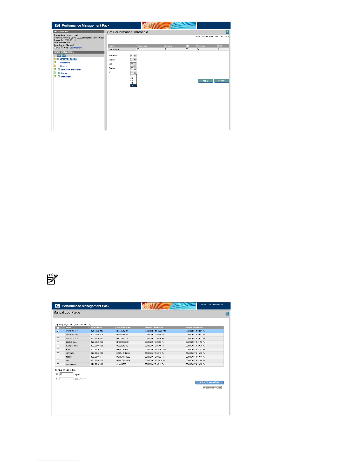
Threshold values
Threshold settings for the various subsystems enable PMP analysis adjustment to account for highly variable
or stable system performance. A higher value used results in smaller average changes in performance. A
higher value used also generates fewer performance bottleneck indications for a server whose performance
changes dramatically. A smaller value can be used for servers with more stable performance or when the
sampling rate is higher.
Manual Log Purge
Manual Log Purge enables the recorded sessions for a logged server or network storage enclosure, logged
in the PMP performance database and occupying hard disk storage space, to be deleted. Use this tool
regularly to remove unwanted recorded sessions and reduce database size.
To delete records in the performance database:
1. From the Systems Insight Manager console toolbar, select Options→Performance Management Pack
Options→Manual Log Purge.
2. Select the server or network storage enclosure for which to delete logged data.
3. Specify to delete data older than a specified number of days or a specified date.
NOTE: Data acquired for the current date of the analysis server cannot be deleted.
4. To remove the data from the performance database, click Delete Selected Data.
74 Monitoring and controlling servers
Page 75
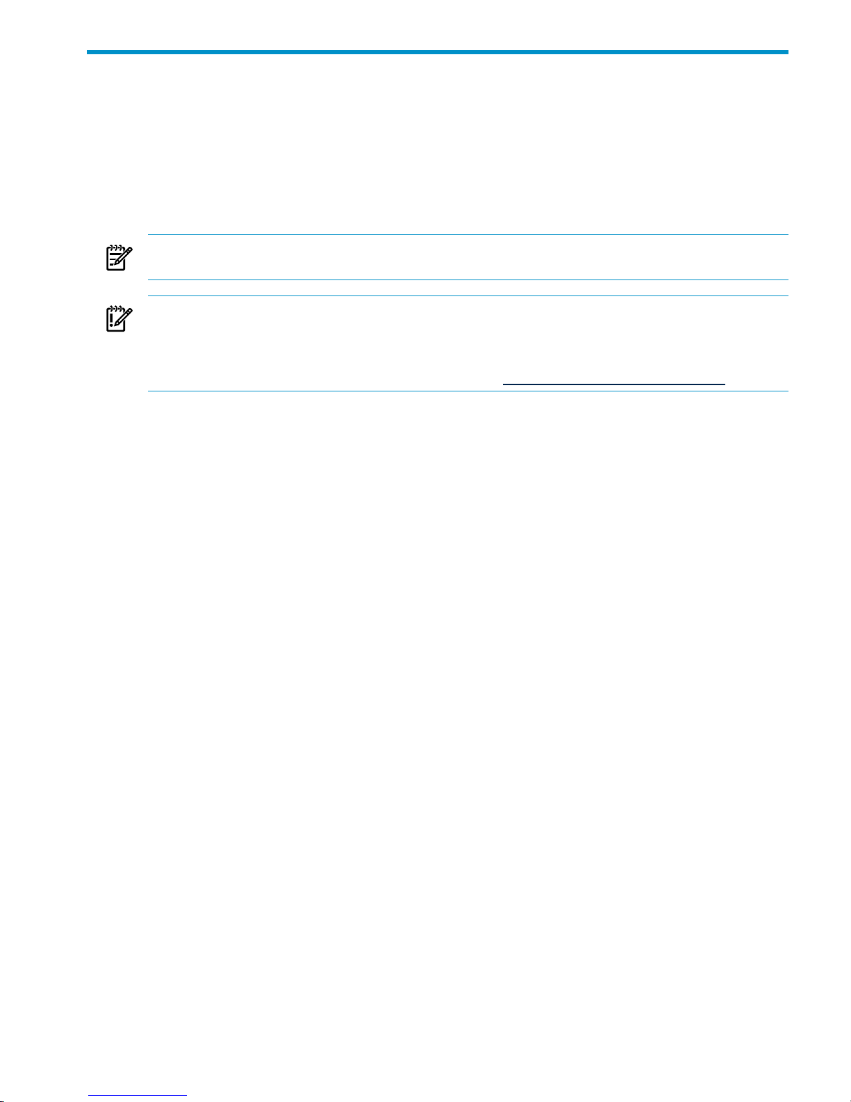
5 Deploying and securing servers
This chapter provides an overview for using the HP Insight Rapid Deployment software to deploy servers
and the HP Vulnerability and Patch Management Pack (VPM) to perform vulnerability scanning and deploy
patches and fixes.
Configuring BladeSystem servers and image installs using the HP Insight
Rapid Deployment software
NOTE: Because of compatibility issues, you must run HP Insight Rapid Deployment software and Ignite-UX
on different subnets.
IMPORTANT: By default, the Create Disk Image and Distribute Disk Image tasks operate on the “first”
disk. The disks are enumerated using a proprietary algorithm. The “first” disk might not be the system boot
disk. The Altiris showdisk utility can be used to generate human-readable disk enumeration output. This utility
is called in the provided Read Hardware Configuration jobs. For more information on reading the showdisk
output, see the Rapid Deployment Pack Knowledge Base at http://www.hp.com/servers/rdp/kb.
Configuring scripted installs
The scripted install jobs use a small image to partition and format the disk. When deploying to a server with
multiple disks, either DAS or SAN, you might have to specify the system boot disk in the job for the NTFS.img
or GRUB.img images.
To specify a particular disk:
1. In the Deployment Server Console, copy, rename, and edit the job.
2. Modify the Distribute Disk Image task.
3. In the Additional Parameters box, add the -dx switch, where x is an integer that represents the
appropriate disk number.
Additionally, for Red Hat Linux in a multiple disk configuration, the kickstart file must specify the system boot
disk.
1. On the Deployment Server, copy and rename the kickstart file.
2. Modify the new kickstart file by replacing the autopart command with separate part command lines
and adding the --ondisk=XXX option to each where XXX is the device label.
Example for non-LVM:
part /boot --size=75 --ondisk=cciss/c0d0part swap –size=1000
--ondisk=cciss/c0d0part / --size 5120 -–grow --ondisk=cciss/c0d0
Example for LVM:
part /boot --size=100 --fstype=ext3 --ondisk=cciss/c0d0part pv.01 --size=100
--grow --ondisk=cciss/c0d0volgroup VolGroup00 -–pesize=32768 pv.01
3. Edit the Run Script – Create Boot Environment task in the job created above to use the new kickstart
file created in step 2.
Configuring SAN-attached scripted install
In addition to the steps in the Configuring-scripted-installs section, some further steps might be necessary.
For VMware ESX Server 3.x, disconnect the SAN. After the operating system install is complete, reconnect
the SAN and create a VMFS datastore on it.
Configuring image installs
When capturing or deploying an image to a server with multiple disks, either DAS or SAN, you might have
to specify the system boot disk in the job.
To specify a particular disk:
Configuring BladeSystem servers and image installs using the HP Insight Rapid Deployment software 75
Page 76
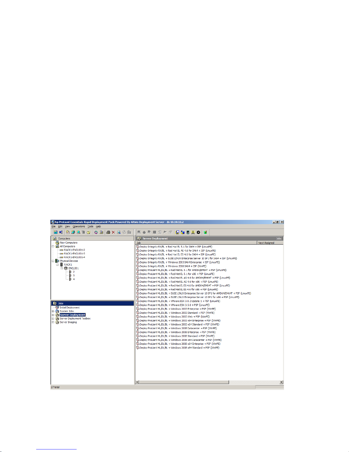
1. In the Deployment Server Console, copy, rename, and edit the job.
2. Modify the Create Disk Image or Distribute Disk Image task.
3. In the Additional Parameters box, add the -dx switch, where x is an integer that represents the
appropriate disk number.
When deploying Linux with LVM, x must be a comma-separated list of integers representing all of the disk
numbers that the LVM volume will span. For example, to deploy an LVM image that spans the first three
disks, use -d1,2,3.
Configuring HP BladeSystem enclosures
The console display name for a new server blade is a combination of the rack name, enclosure name, and
bay number. Before you connect the first blade in an enclosure to the Deployment Server, assign unique
names to the rack and enclosure to prevent conflicting database entries.
To change the rack and enclosure names, follow the procedure specific to each server type:
• HP BladeSystem c-Class servers—Access the Onboard Administrator and change the rack name and
the enclosure name. See the server documentation for complete details.
• ProLiant BL p-Class servers—Place at least one server blade in each enclosure, and before powering
up the server blade, change the rack and enclosure information using the Integrated Lights-Out (iLO)
interface. See the server documentation for complete details.
If the rack and enclosure names are changed after the blades have appeared in the console, then the blades
must be rebooted for the new rack and enclosure names to be discovered and the original rack and enclosure
names must be manually deleted from the Physical Devices View in the console.
Using HP Insight Rapid Deployment software
Deployment Console basics
Computers Pane—This pane shows managed computers. The New Computers group shows computers that
have connected to the Deployment Server for the first time. Click View→Show Physical Devices to add
the Physical Devices group.
Jobs Pane—This pane shows the provided jobs.
76 Deploying and securing servers
Page 77

Details Pane—The right-hand side of the console displays information about the selected computer or job.
For a computer, basic properties and job history appear. For a job, tasks and computer history appear. The
Job Schedule Information dialog box displays the status of each task in the schedule. To view this dialog
box, double-click an item in the job history or computer history. The Schedule Status Detail dialog box
displays return codes and status messages. To view this dialog box, click Status Details.
To execute a job, drag and drop one or more computers onto a job, or vice-versa.
Connecting server blades
1. Connect the enclosure to the network that contains your Deployment Server, and power up the enclosure.
2. Insert the server blades into the enclosure, but do not power up the server blades.
3. Change the default rack and enclosure names.
4. Power up the server blades.
5. From the Computer pane, right-click on a server blade and select Power Control→iLO – Interface.
This action accesses the iLO homepage.
Using HP Insight Rapid Deployment software 77
Page 78
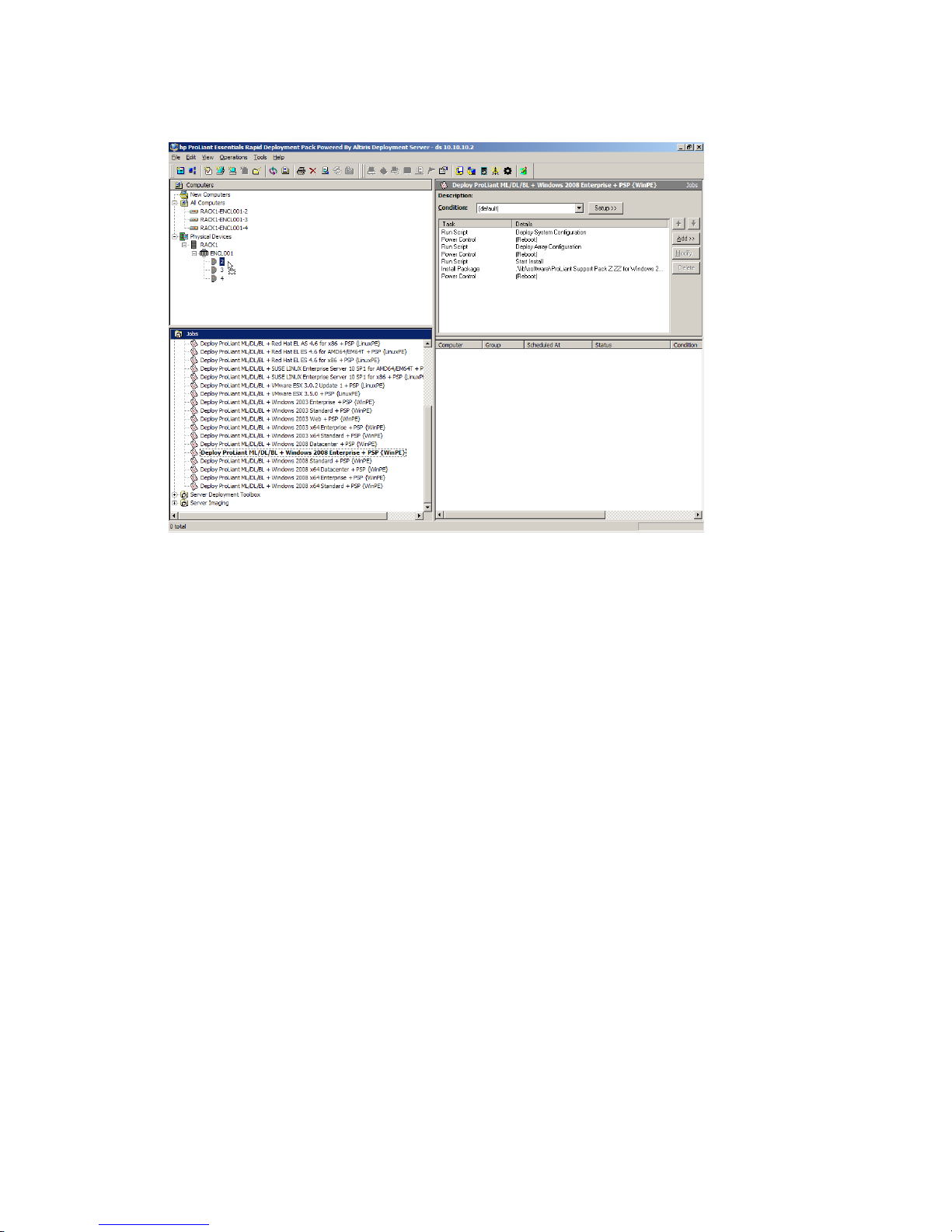
Deploying the first server blade
1. In the Jobs pane, in the Server Deployment folder, select a Windows scripted installation job. Drag the
job to the server blade in the Computers pane.
2. Select Run this job immediately, and click OK.
3. To view the progress of the job, double-click the computer in the job’s computer history.
Reconfiguring the server blade
By default the Windows scripted installation job configures the computer name as the console display name
and configures the network as DHCP.
If you need to reconfigure the server:
1. In the Computers pane, right-click the blade and click Configure.
2. Click Microsoft Networking, and enter a new computer name and a new workgroup or domain name.
3. Click TCP/IP, and enter the appropriate IP information.
4. Click OK.
5. Select Run this job immediately, and click OK.
6. If the Windows scripted installation job is still running, click OK when the warning message appears.
Vulnerability scanning and deploying patches and fixes
This section describes the setup and use of the HP Vulnerability and Patch Management Pack; scanning
functionality.
HP Vulnerability and Patch Management Pack (VPM) overview
The following figure illustrates the process for using Vulnerability and Patch Management.
78 Deploying and securing servers
Page 79
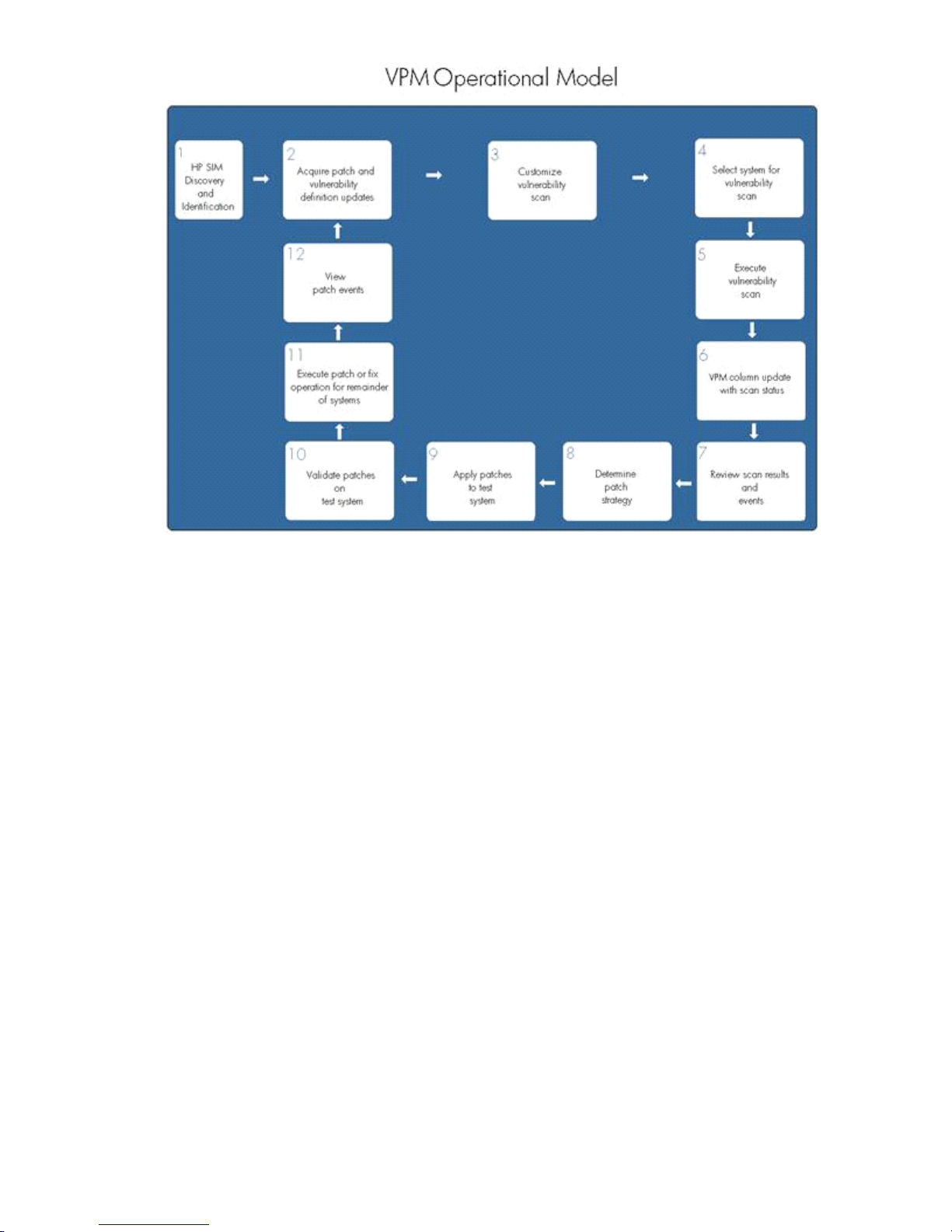
For more information about VPM requirements, installation instructions, and VPM troubleshooting, see HP
Vulnerability and Patch Management infrastructure requirements and additional VPM functionality.
Provided scan definitions
HP Vulnerability and Patch Management Pack provides a large variety of scan definitions. You can use these
definitions to search for vulnerabilities or modified scans to suit the specific needs of your environment. For
specific information about the provided scan definitions, see "HP Vulnerability and Patch Management
infrastructure requirements and additional VPM functionality."
Scanning for vulnerabilities
1. Select Diagnose→Vulnerability and Patch Management→Scan→Scan for Vulnerabilities .
2. Select the target systems to scan by selecting a group from the list or by selecting the individual system,
and click Apply.
3. Verify that the correct target systems appear in the lists, click Add Targets or Remove Targets if it is
necessary to reselect target systems, and click Next.
4. If any selected systems are unlicensed or licensed with a time-limited license, you can apply permanent
licenses at this time. If licenses are available, select any unlicensed system in the list to license, and click
Apply License. Server and client licenses are automatically applied to the appropriate systems, if
available. To add licenses using a key string, click Add Key, enter the key string in the field, and then
click OK.
If you select any systems listed as Unknown or Unmanaged in HP SIM for licensing, a server license is
assumed and automatically applied. HP recommends that you modify the HP SIM settings to properly
identify systems before licensing. Any unlicensed target systems are not included in the patch agent
deployment.
If one or more target systems can use a VPM client license, and adequate client licenses are not available,
you are prompted to select if you want to apply server licenses (if available) to license the selected client
systems. After you apply a license, the license cannot be revoked or replaced with a VPM client license
later.
The license validation page does not appear if all target systems initially selected for the task are licensed
with permanent licenses.
Vulnerability scanning and deploying patches and fixes 79
Page 80

5. Click Next.
6. Enter a name for the vulnerability scan, and select a scan definition from the list.
7. To deploy patches immediately, click Run Now. To schedule the patch deployment, click Schedule
and complete the following instructions:
a. Enter a name for the deployment task or accept the default name, and select Once.
b. Designate a time and date to run the patch deployment task, and click Done.
You can view scan results after the task completes either by clicking the system status icon or viewing
the VPM Events list.
Viewing, modifying, or canceling a scheduled task
1. Select Tasks & Logs→View All Scheduled Tasks.
2. Select the appropriate task from the list, and then click Edit.
3. Review the event details to modify. If necessary, you can change the target systems on which the task
is scheduled to run by clicking either Add Targets or Remove Targets, and then click Next.
4. Review the task schedule, modify as necessary, and then click Done.
Viewing vulnerability scan results
You can view VPM scan results for a specified vulnerability scan or for an individual system. When a
vulnerability scan is run for a group of target systems, results are generated for the group as well as for each
individual system. You can view vulnerability scan results as .pdf files in any of the following formats:
• Executive Summary—A high-level summary of all vulnerabilities found in a scan
• Detailed Listing—A list of vulnerabilities found on each system, as well as a description and risk
evaluation of each
• Simple Listing—A list of vulnerabilities found on each system sorted by vulnerability name
• Scan Summary—A list of scans performed and vulnerabilities found, sorted by system name
• Ports and Services—A list of ports, services, and unknown services, sorted by system name
Vulnerability scan results guidelines
• Vulnerability scan results cannot be viewed or deleted while status displays “Scanning” or “Pending”.
Vulnerability scan results for an aborted scan might not be accurate.
• If the vulnerability scan results display the message, “No file access”, check the WBEM settings in
HP SIM for appropriate credentials to the target systems. For additional information, see the user guide.
• Scan results can also be accessed from the links in the completed scan event in HP SIM.
• Vulnerabilities listed are the total vulnerabilities found in the group of systems scanned. Individual
systems in the group might not have every vulnerability listed.
Viewing vulnerability scan results by scan name
1. Select Diagnose→Vulnerability and Patch Management→Scan→View Results by Scan Name.
2. Select the appropriate vulnerability scan, select the format in which to view the results from the list, and
click View.
The vulnerability scan results appear in a separate window.
Viewing vulnerability scan results by scan system
1. Select Diagnose→Vulnerability and Patch Management→Scan→View Results by System.
2. Select individual system for which to view scan results, and click Apply.
3. Verify that the correct target systems appear in the lists, and click Next.
If you need to reselect the target systems, click Add Targets or Remove Targets, verify the target
systems, and then click Next.
80 Deploying and securing servers
Page 81

Results for all scans performed on the selected system appear.
4. Select the scan results to view, and click View.
Customizing vulnerability scan definitions
You can create custom scans from the default system scans. Custom scans are updated automatically with
the corresponding vulnerability updates when the default system scans are updated.
To customize the provided vulnerability scans or previously created custom vulnerability scans:
1. Select Diagnose→Vulnerability and Patch Management→Customize Scan.
2. Select a default system scan or a previously created custom scan to modify, and then click Edit. A list
of vulnerabilities appears. Clicking the entry in either the Vulnerability ID or Advisory column displays
additional information about the vulnerability.
3. Select one or more vulnerabilities to include in the custom scan definition.
4. Enter a name and description for the new customized scan, and click Save.
You must rename the customized vulnerability scan. You cannot save a modified default Vulnerability
and Patch Management scan using the original scan name.
You can delete only custom vulnerability scans. You cannot delete the default system scans provided with
VPM.
To delete a customized scan:
1. Select Diagnose→Vulnerability and Patch Management→Customize Scan.
2. Select the custom vulnerability scan to delete, and click Delete.
3. To confirm the deletion, click OK when prompted.
Deleting scan results
Vulnerability and Patch Management scan results can be deleted for a specified scan or for an individual
system. Removing results breaks the links to the results in the events and the system list. Run another scan to
create new results for the system.
Deleting scan results by scan name
1. Select Diagnose→Vulnerability and Patch Management→Scan→View Results by Scan Name.
2. Select the appropriate scan or scans, and then click Delete. All results associated with the selected scan
are deleted.
Deleting scan results by system
1. Select Diagnose→Vulnerability and Patch Management→Scan→View Results by System.
2. Select the individual system for which you want to delete the results from, and then click Apply.
3. Verify that the correct target systems appear in the lists. To reselect target systems, click Add Targets
or Remove Targets, and then click Next.
4. Results from all scans performed on the selected system appear. Select the scan results to delete, and
then click Delete.
Deploying patches and fixes
The following sections describe deploying HP Vulnerability and Patch Management Pack patches and fixes.
Deploying patches and fixes based on a vulnerability scan
You can deploy patch and configuration fixes immediately or schedule them for deployment later. You can
select patches individually from the database for deployment to all systems or any combination of specified
systems without performing a scan, or deploy patches and fixes for all vulnerabilities identified in a particular
scan.
Patches that come from software vendors can update existing software, registry, or configuration settings or
files. Configuration fixes resolve incorrect system settings that can leave the system open to security threats,
such as open ports or services running that are not required.
Vulnerability scanning and deploying patches and fixes 81
Page 82
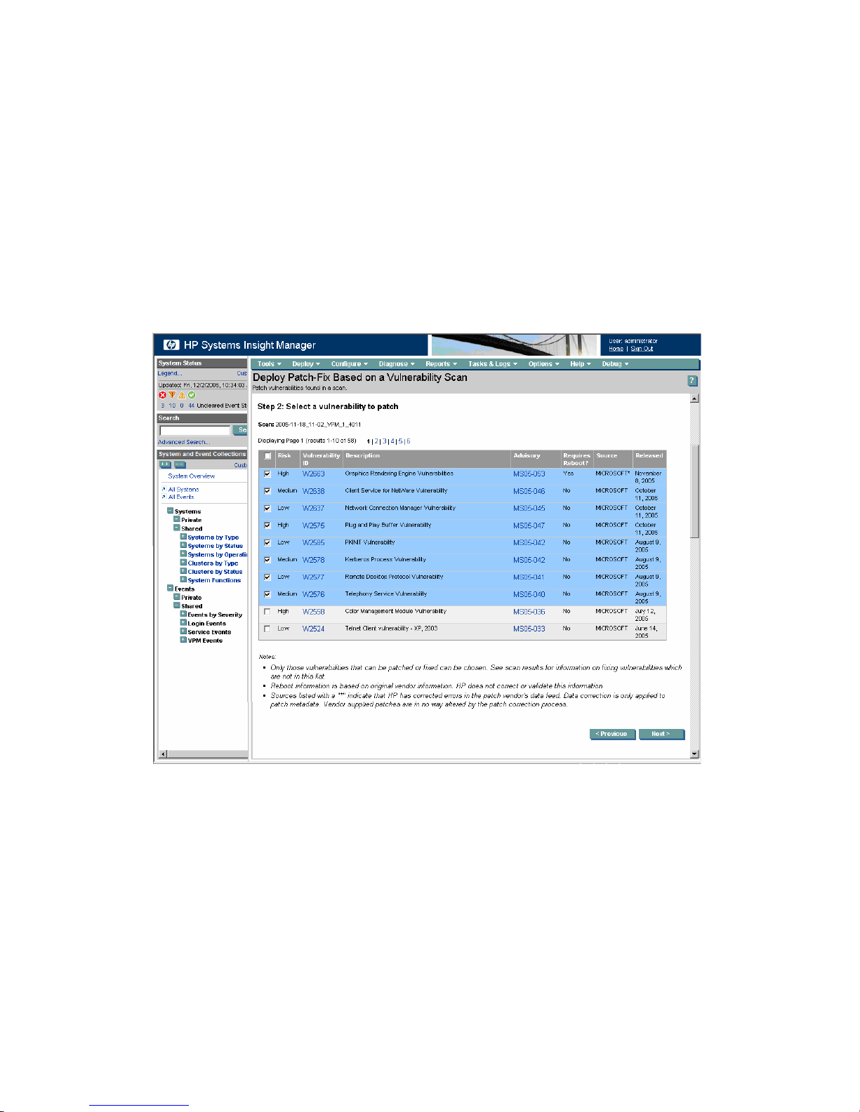
Some vulnerability issues found cannot be automatically fixed or patched. Scan results often provide a
suggested fix that you must deploy manually.
If after a performing a vulnerability scan, the scan determines that a security vulnerability or configuration
error exists, complete the steps in the following sections to deploy patches, configuration fixes, or both to
update the system. Vulnerabilities that require manual fixes or vulnerabilities for which the patch has not
been acquired are listed but not available for selection.
To deploy patches, configuration fixes, or both to systems based on a specific vulnerability scan:
1. Select Deploy→Vulnerability and Patch Management→Patch-Fix Based on a Scan.
2. To display the vulnerabilities for all systems included in the scan, select the completed vulnerability scan,
and then click Next.
All vulnerabilities listed might not be applicable for every system. Clicking the entry in the Vulnerability
ID or Advisory column displays additional information about the vulnerability. The Requires Reboot
column indicates if the patch requires the system to reboot after deployment.
3. Select the vulnerabilities to patch or fix, and click Next.
4. Select the systems you want to apply patches or fixes, and click Next.
82 Deploying and securing servers
Page 83
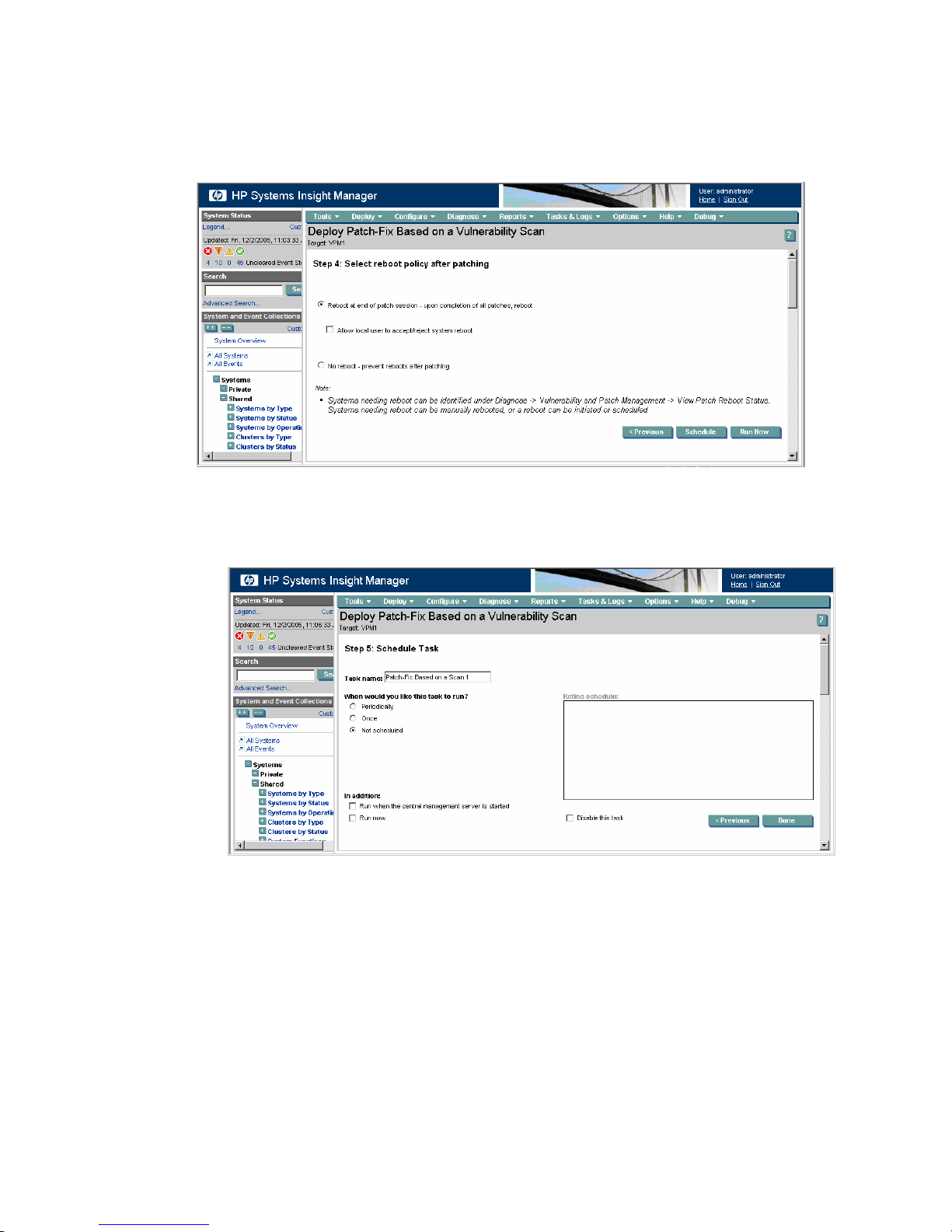
5. Designate when the patched systems are rebooted. You can perform reboots immediately after the
patches or fixes are installed or postpone the reboot. You can also give the local user the option to
accept or reject the reboot.
If the local user rejects the reboot, there is not another automatic reminder.
6. To deploy patches immediately, click Run Now.
To schedule the patch deployment, click Schedule and complete the following instructions:
a. Enter a name for the deployment task or accept the default name, and select Once.
b. Designate a time and date to run the patch deployment task, and click Done.
To view the list of target systems that require reboot, see Viewing patch reboot status.
Deploying patches without a vulnerability scan
If a patch is released that must be deployed immediately, you can apply the patch without running a scan.
In normal circumstances, HP recommends running a scan before deploying patches. To deploy patches to
target systems without running a scan:
1. Select Deploy→Vulnerability and Patch Management→Patch without a Scan.
2. Select the target systems to patch either by selecting a group from the list or by selecting the individual
systems, and click Apply.
3. Verify that the correct target systems appear in the lists, and click Next.
If you need to reselect the target systems, click Add Targets or Remove Targets, verify the target
systems, and then click Next.
Vulnerability scanning and deploying patches and fixes 83
Page 84

4. If any selected systems are unlicensed or licensed with a time-limited license, you can apply permanent
licenses at this time. If licenses are available, select any unlicensed system in the list to license, and click
Apply License. Server and client licenses are automatically applied to the appropriate systems, if
available. To add licenses using a key string, click Add Key, enter the key string in the field, and then
click OK.
If you select any systems are listed as Unknown or Unmanaged in HP SIM for licensing, a server license
is assumed and automatically applied. HP recommends that you modify the HP SIM settings to properly
identify systems before licensing. Any unlicensed target systems not licensed at this time are not included
in the patch agent deployment.
If one or more target systems can use a VPM client license, and adequate client licenses are not available,
you are prompted to select if you want to apply server licenses (if available) to license the selected client
systems. After you apply a license, the license cannot be revoked or replaced with a VPM client license
later. If all target systems initially selected for the task are licensed with permanent licenses, the license
validation page does not appear.
5. Click Next. All patches included in the patch database display. To display additional information about
the patch, click the entry in the Vulnerability ID or Advisory column. The Requires Reboot column
indicates if the patch requires the system to reboot after deployment.
6. Select the vulnerabilities to patch, and click Next.
7. Designate when the patched systems are rebooted. Reboots can be performed immediately after the
patches or fixes are installed or postponed until later. The local user can also be given the option to
accept or reject the reboot. If the local user rejects the reboot, there will not be another automatic
reminder.
8. To deploy patches immediately, click Run Now. To schedule the patch deployment, click Schedule
and complete the following instructions:
a. Enter an appropriate name for the deployment task or accept the default name, and select Once.
b. Designate a time and date to run the patch deployment task, and click Done.
To view the list of target systems that require reboot, see Viewing patch reboot status.
Viewing the patch repository
1. Select Diagnose→Vulnerability and Patch Management→View Patch Repository.
2. To filter the list of displayed patches, select the appropriate patch source from the list. To view information
about a specific patch, click the patch identification number in the Advisory or Vulnerability ID column.
Viewing patch reboot status
Certain patches require a server reboot after installation. During patch deployment, you can have the option
to reboot the server later. The patch deployment is not complete until after the server is rebooted.
To view the patch status and initiate reboots for selected systems:
84 Deploying and securing servers
Page 85
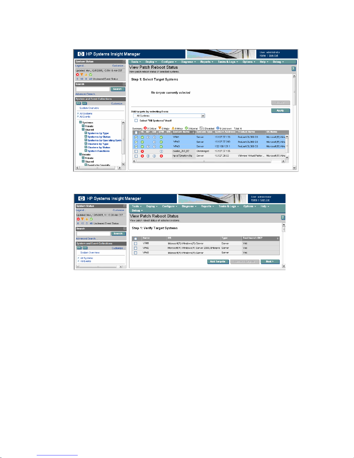
1. Select Deploy→Vulnerability and Patch Management→View Patch Reboot Status.
2. Select the target systems for which to view the reboot status either by selecting a group from the list list
or by selecting individual systems, and click Apply.
3. Verify that the correct target systems appear in the lists, and click Next.
If you need to reselect the target systems, click Add Targets or Remove Targets, verify the target
systems, and then click Next.
The patch reboot status for the selected systems appears in the Reboot Status column.
Vulnerability scanning and deploying patches and fixes 85
Page 86
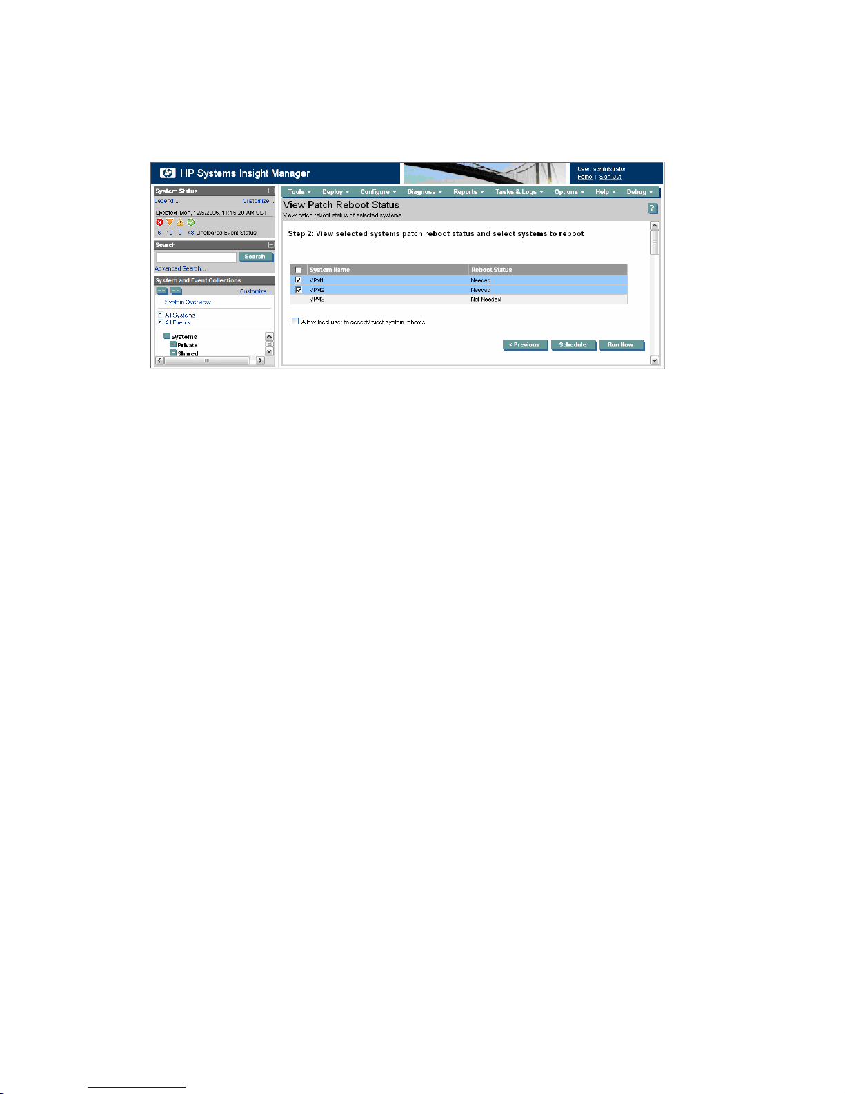
4. Select the systems to reboot, and select if the local user of all the listed systems will be given the option
to accept or reject the reboot.
If the local user rejects the reboot, there is not another automatic reminder. The Reboot Status column
does not indicate a reboot is required for the systems until after the patch deployment task is complete.
5. To reboot the selected systems immediately, click Run Now.
To schedule the reboot, click Schedule and complete the following instructions:
a. Enter a name for the reboot task or accept the default name, and select Once.
b. Enter a time and date to run the patch removal task, and click Done.
Validating installed patches
Patch validation identifies any missing patches on target systems and immediately reinstalls the patch, creating
a patch deployment event in HP SIM. If a VPM Patch Agent update has been acquired, the update is also
automatically applied. If reinstalled patches require selected target systems to be rebooted, this action is
automatically deferred.To view the reboot status after the validation task is complete, select
Diagnose→Vulnerability and Patch Management→View Patch Reboot Status.
To validate installed patches:
1. Select Deploy→Vulnerability and Patch Management→Validate Installed Patches.
2. Select the target systems for which to validate installed patches either by selecting a group from the list
list or by selecting individual systems.
3. Click Apply.
4. Verify that the correct target systems appear in the lists, and click Next.
If you need to reselect the target systems, click Add Targets or Remove Targets, verify the target
systems, and then click Next.
5. Enter a name for the validation task, or accept the default name.
6. To validate the installed patches immediately, select Run now, and click Done. To schedule the validation
task, do one of the following:
• To run on a regular basis, select Periodically.
• To run the task one time, select Once. Designate a time and date to run the validation task, and
click Done. You can schedule multiple patch validation tasks at different frequencies for groups
of target systems.
You can view task results in the VPM Events list after the task completes.
Removing patches
You can remove only patches that display on the patch removal page. These patches include only patches
that were installed by the Vulnerability and Patch Management and that are Microsoft patches or
vendor-provided patches with a removal option. The Vulnerability and Patch Management cannot remove
configuration fixes or Red Hat patches. The Vulnerability and Patch Management does not perform dependency
checking before removing patches. HP recommends using extreme care when removing patches.
86 Deploying and securing servers
Page 87
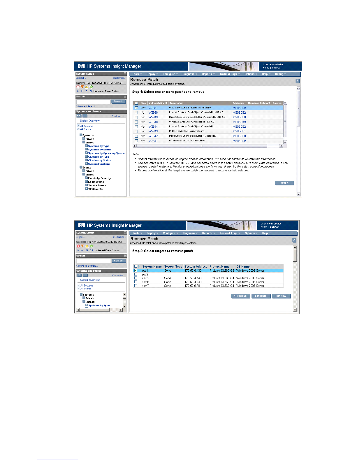
To remove patches previously applied to systems:
1. Select Deploy→Vulnerability and Patch Management→Remove Patch.
2. Select the patches to remove, and click Next.
Some patches might require a manual reboot of the target system to completely remove the patch.
3. Select the systems you want to remove the designated patches.
Vulnerability scanning and deploying patches and fixes 87
Page 88
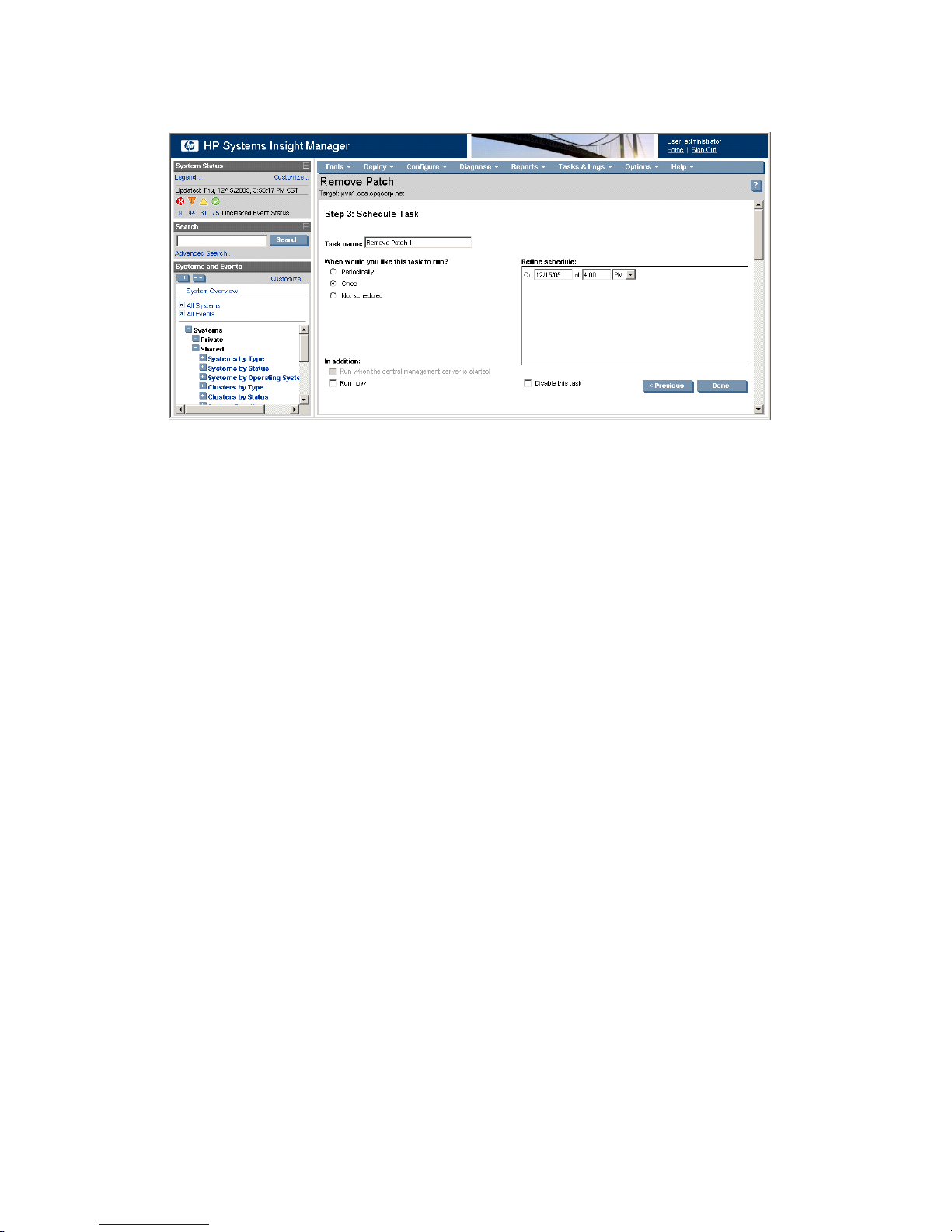
4. Select the systems you want to apply the patches or fixes, and click Next.
5. To remove patches immediately, click Run Now. To schedule the patch removal, click Schedule and
complete the following instructions:
a. Enter an appropriate name for the deployment task or accept the default name, and select Once.
b. Designate a time and date to run the patch deployment task, and click Done.
If patch removal requires a target system reboot, this action is automatically deferred. To review the
reboot status of a system after completing a patch removal task, select Deploy→Vulnerability and
Patch Management→View Patch Reboot Status.
Redeploying the VPM Patch Agent
The VPM Patch Agent automatically deploys when target systems are licensed. If the VPM Patch Agent
deployment fails, verify that the WBEM credentials are configured correctly. To verify the WBEM credentials,
select Options→Protocol Settings→System Protocol Settings.
If the VPM Patch Agent is removed from a system for any reason or is not properly deployed to the target
system, redeploy the VPM Patch Agent.
To deploy the VPM Patch Agent:
1. Select Deploy→Vulnerability and Patch Management→VPM Patch Agent.
2. Select the target systems on which to deploy the VPM Patch Agent either by selecting a group from the
list or by selecting individual systems, and click Apply.
3. Verify that the correct target systems appear in the lists, and click Next.
If you need to reselect the target systems, click Add Targets or Remove Targets, verify the target
systems, and then click Next.
4. If any selected systems are unlicensed or licensed with a time-limited license, you can apply permanent
licenses at this time. If licenses are available, select any unlicensed system in the list to license, and click
Apply License. Server and client licenses are automatically applied to the appropriate systems, if
available. To add licenses using a key string, click Add Key, enter the key string in the field, and click
OK.
If you select any systems listed as Unknown or Unmanaged in HP SIM for licensing, a server license is
assumed and automatically applied. HP recommends that you modify the HP SIM settings to properly
identify systems before licensing. Any unlicensed target systems not licensed at this time are not included
in the patch agent deployment.
If one or more target systems can use a VPM client license, and adequate client licenses are not available,
you are prompted to select if you want to apply server licenses (if available) to license the selected client
systems. After you apply a license, the license cannot be revoked or replaced with a VPM client license
later. The license validation page does not appear if all target systems initially selected for the task are
licensed with permanent licenses.
88 Deploying and securing servers
Page 89
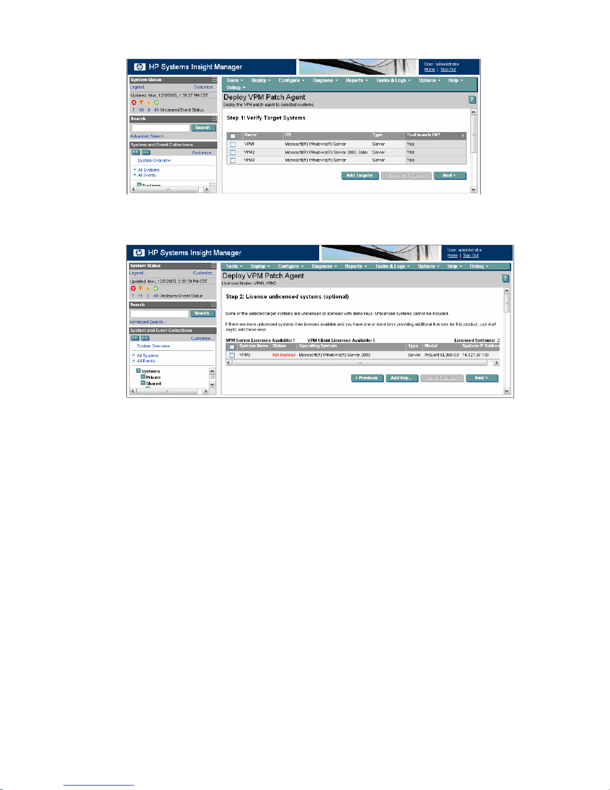
5. Click Next.
6. If the server type is identified as Unknown or Unmanaged with no identified operating system in the
HP SIM console, select the appropriate operating system, and click Next.
7. To deploy the agent immediately, select Run now, and click Done. To schedule the agent deployment,
select Once, designate the appropriate date and time, and click Done.
You cannot apply patches to the systems until after the scheduled task completes and the VPM Patch
Agent is applied successfully.
You can view task results in the VPM Events list after the task completes.
HP Vulnerability and Patch Management Pack events
HP Vulnerability and Patch Management Pack creates events in HP SIM. These events can be viewed with
all HP SIM events in the Events list, or independently in the VPM Events list. For a complete listing of events
see "HP Vulnerability and Patch Management infrastructure requirements and additional VPM functionality."
Vulnerability scanning and deploying patches and fixes 89
Page 90

90
Page 91
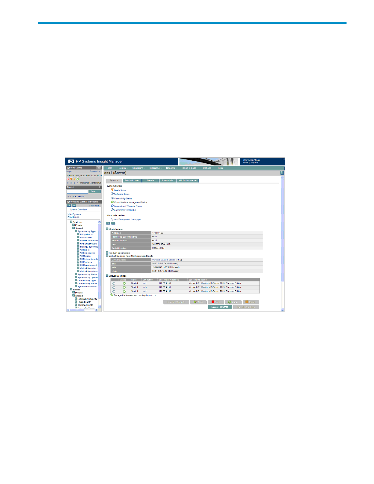
6 Using HP Virtual Machine Management Pack
This chapter provides an overview of server virtualization and consolidation using the Virtual Machine
Management Pack component of Insight Control Environment. This component might be installed as part of
an Insight Control Environment suite installation, but the component is licensed separately.
Virtual Machine Management Pack interface overview
Virtual Machine Management Pack provides central management and control for virtual machines with
Microsoft Virtual Server 2005, Hyper-V, VMware Server, VMware ESX Server, HP integrated Citrix XenServer,
or Xen on RHEL or SLES. Virtual Machine Management Pack is integrated with HP SIM.
Virtual Machine Management Pack detects virtual machine status changes initiated by other supported
virtualization management consoles. The System Status icons on the HP SIM System Page indicate these
status changes. To access the System Page, click the system name in the HP SIM console. If Microsoft
Virtual Server or Hyper-V is used, the Launch SCVMM button appears. If VMware ESX Server or HP integrated
VMware ESXii is used, the Launch VC button appears.
The left frame of the HP SIM console displays a node navigational tree. A list of the virtual machine hosts
and their virtual machine guests appears in the Systems→Shared→Systems by Type directory.
To display all virtual machine hosts and guests managed by Virtual Machine Management Pack in the HP SIM
console, expand the Systems→Shared→Systems by Type directory in the navigational tree, and then
click All Virtual Machine Hosts or All Virtual Machines.
Virtual machine host
Depending on the host configuration, additional details might appear in addition to those listed. To display
the following information for the host, click a virtual machine host in the HP SIM console, and then click the
System tab.
• If Microsoft Virtual Server or Hyper-V is used, then the Launch SCVMM button appears.
• If VMware ESX Server or HP integrated VMware ESXi is used, then the Launch VC button appears.
Virtual Machine Management Pack interface overview 91
Page 92
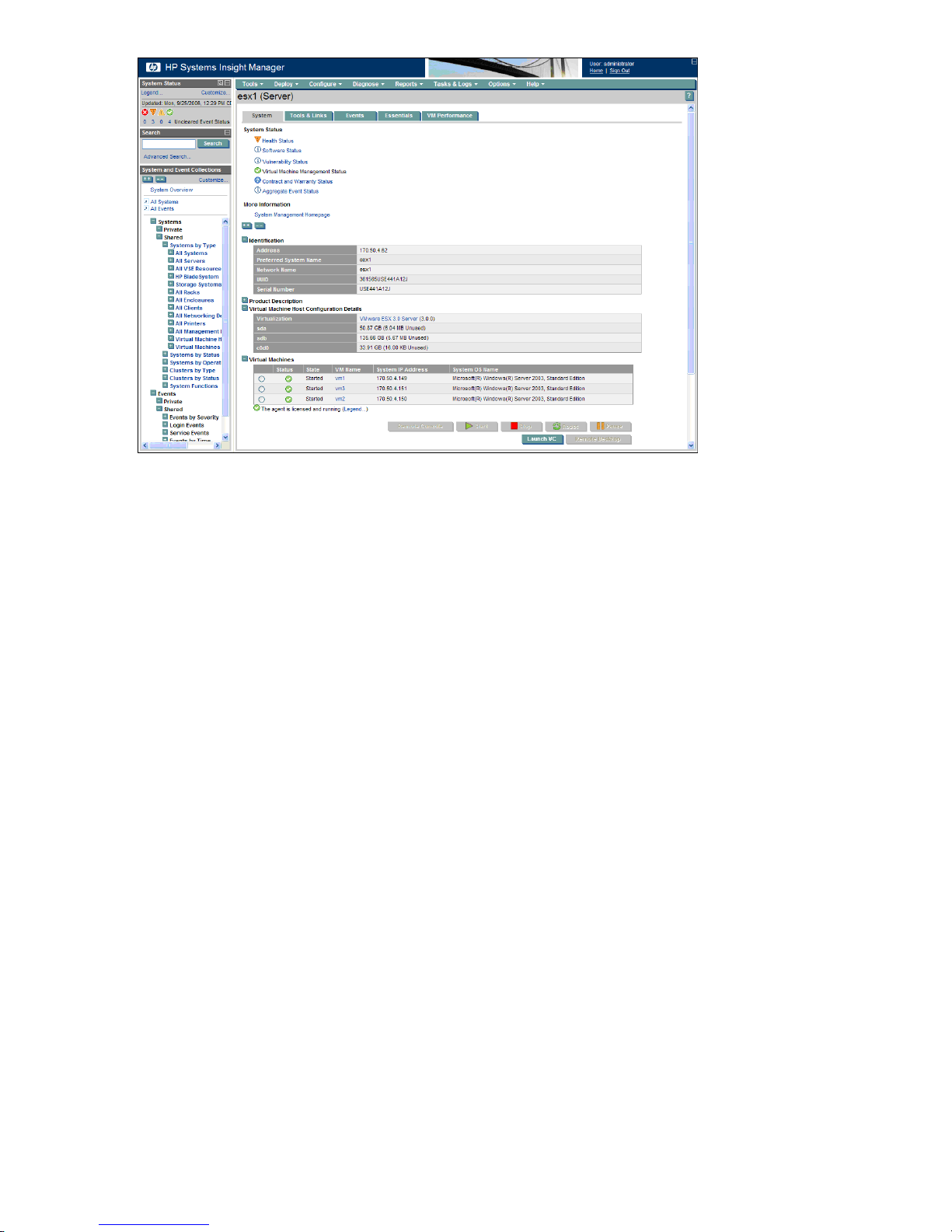
• System status—The health and virtual machine status
• Identification—The address, preferred system name, and network name
• Product description
System type—The type of system on which the software is running•
• System subtype—A virtual machine host or guest
• Hardware description—Details of the physical system on which the software is running
• OS name—The operating system used
• OS for tool filtering—The type of operating system being used for filtering
• OS description—The level of operating system being used
• OS version—The version of the operating system
• Management protocols—The protocols being used for tool filtering
• Virtual Machine Host Configuration Details
Virtualization—The type of virtualization software installed•
• VMM Agent version—The current VMM Agent version
• Alternate Host for—The alternate host information
• Storage details—The disk space information
• Virtual machines—A list of virtual machines associated with the virtual machine host
Status—The status of the virtual machine•
• State—The state of the virtual machine
• VM name—The name of the virtual machine
• System IP address—The IP address of the virtual machine
• Legend—Button that displays the VMM Status Icon Legend window
• VM control—Controls that enable you to launch the Remote Desktop and the Remote Console, as
well as start, stop, reset, and pause the virtual machine
• Disk partitions—A list of how the disk is separated, its capacity, and percentages of used and available
space
92 Using HP Virtual Machine Management Pack
Page 93
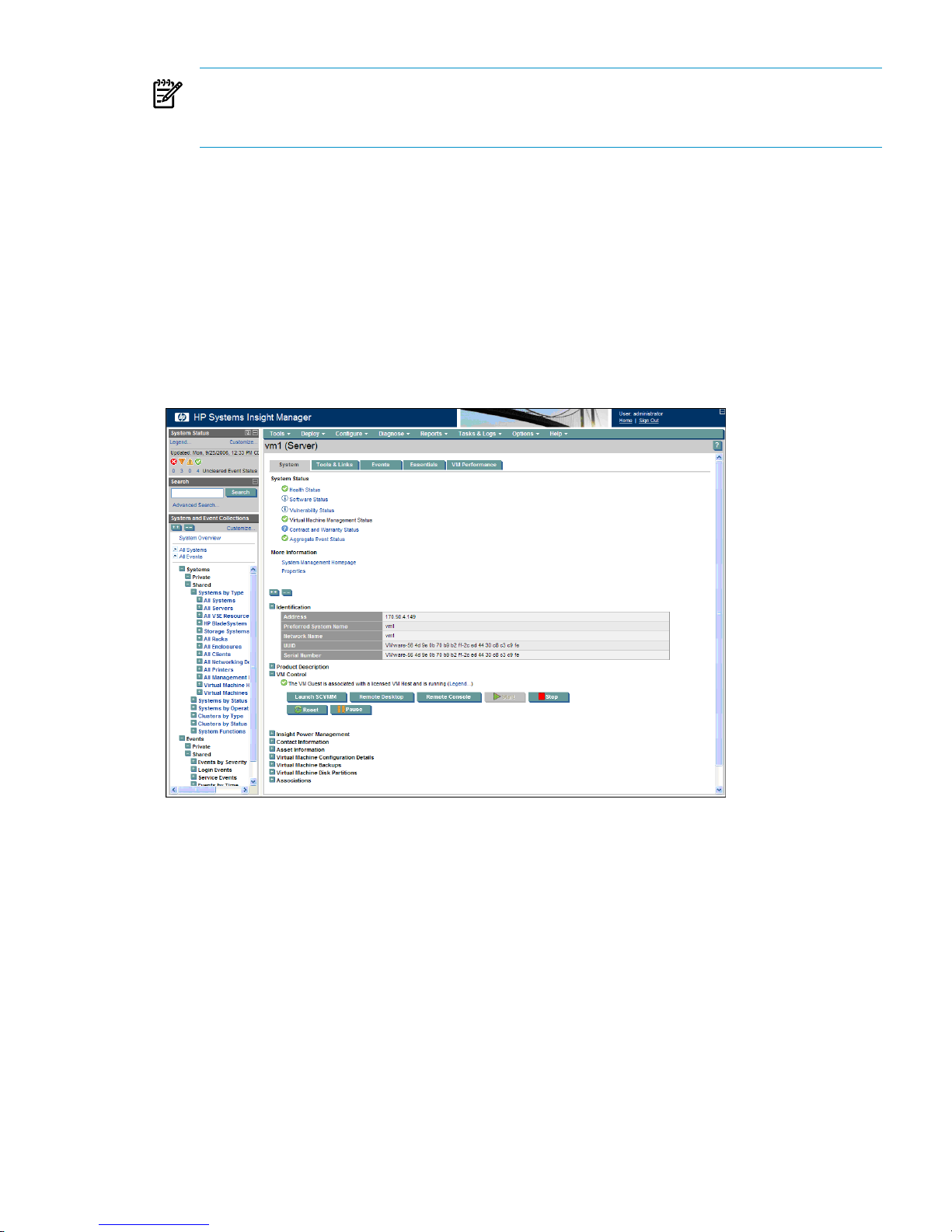
NOTE: For HP integrated Citrix XenServer a forward slash (/) is added at the beginning of the storage
repository name in the Disk partition column.
For Xen hypervisors, No data available appears in the Disk Partitions section.
• VirtualCenter information—Details about VirtualCenter, such as IP address of the host system and virtual
machines associated with VirtualCenter
• Associations—A list of associations as created by HP SIM
Virtual machine guest
Depending on the guest configuration, additional details might appear. To display the following configuration
information for the host or guest, click a virtual machine guest in the HP SIM console, and then click the
System tab. Information appears only for the virtual machine guests that are fully configured.
• If Microsoft Virtual Server or Hyper-V is used, then the Launch SCVMM button appears.
• If VMware ESX Server or HP integrated VMware ESXi is used, then the Launch VC button appears.
• System status—The health and virtual machine status
• Identification—The address, preferred system name, and network name
• Product description
System type—The type of system on which the software is running•
• System subtype—A virtual machine host or guest
• Hardware description—Details of the physical system on which the software is running
• OS name—The operating system being used
• OS for tool filtering—The type of operating system being used for filtering
• OS description—The level of operating system being used
• OS version—The version of the operating system
• Management protocols—The protocols being used for tool filtering
• Virtual machine controls—Controls that enable you to launch the Remote Desktop and Remote Console,
as well as start, stop, reset, and pause virtual machines
Virtual machine guest 93
Page 94

• Virtual machine configuration details
Virtual machine host—The system name of the virtual machine host•
• Virtualization—The virtualization technology installed on the virtual machine host
• Alternate host—The failover host set by the user
• Configuration file—The name and location of the configuration file
• Configuration folder—The name and location of the configuration folder
• Memory—The amount of memory on the virtual machine host
• Virtual NIC—The type of network card and MAC address
• Virtual disk—The type of virtual disk
• CD/DVD RM—Details about the drive
When the host CD/DVD drive is selected while adding a CD/DVD drive to a Hyper-V virtual
machine, a lengthy string (for example,
IDE\CDROMTEAC_DW-224E-V________C.CA__\53C5E1CB00.0.0) might appear in the
Virtual Machine configuration details. This string varies based on the type of CD/DVD drive
attached. This string does not affect functionality.
• Floppy drive—Identity of the floppy drive
• Virtual machine backups—Information about the backups for the virtual machine
Source host—The host source name•
• Source path—The source path
• Configuration file—The configuration file name
• Virtualization layer—The virtualization layer
• Backup repository—The backup repository information
• Backup repository location—The location of the backup repository
• Date—The date of the last backup
• Virtual machine disk partition—A list of virtual machines controlled by the host
Disk name—The name of the disk•
• Partition—The partition on the drive where the disk is found
• Capacity—The capacity of the disk
• %Used—The percentage of disk space used
• Format—The format type of the disk
• Type—The type of disk used
NOTE: For HP integrated Citrix XenServer and HP integrated VMware ESXi, Partition, Format, and
Type information might not be available.
For HP integrated Citrix XenServer %Used and %Available information might not be available.
• VirtualCenter information—Details about VirtualCenter, such as IP address of the host system and virtual
machines associated with VirtualCenter (only available for VMware ESX and HP integrated VMware
ESXi servers).
• Backup details—Details about the most recent backup of the virtual machine, such as source host IP
address, source path, configuration file, virtualization layer, and backup repository
To view completed events involving the selected host or guest, click the Events tab.
Configured and unconfigured virtual machine hosts
Configured and unconfigured virtual machine hosts can appear in HP SIM CMS and have the following
attributes.
94 Using HP Virtual Machine Management Pack
Page 95

Configured
Configured virtual machines meet at least one of the following criteria:
• Proper providers have been installed and the credentials are saved in HP SIM.
• HP SIM can discover and identify the guest operating system running inside the virtual machine host
and with the virtual machine serial number.
• Proper virtual machine host to virtual machine guest association appears.
• Full Virtual Machine Management Pack functionality is available.
• Turning off the virtual machine host does not change its status as a configured virtual machine.
• If the virtual machine host is deleted using the HP SIM interface, then the virtual machine host becomes
unconfigured until HP SIM rediscovers it.
Unconfigured
Unconfigured virtual machines meet at least one of the following criteria:
• Have never been powered on.
• Have no guest operating system installed.
• Do not have proper providers installed.
• Have credentials unknown to HP SIM.
Unconfigured virtual machines can create templates.
Task execution process
You can perform multiple Virtual Machine Management Pack tasks involving separate virtual machine hosts
or virtual machine guests simultaneously, but these tasks take longer to execute than if only one task is
running.
If multiple Virtual Machine Management Pack tasks involving the same virtual machine host or virtual machine
guest are queued at the same time, then the tasks are executed sequentially. One Virtual Machine Management
Pack read function and one write function can be performed simultaneously for each virtual machine host.
Additional functions are queued.
Using Virtual Machine Management Pack controls and tools
You can perform various tasks using Virtual Machine Management Pack controls, available from the HP SIM
host or virtual machine System Page, as described in the following sections. You must have administrative
rights to perform Virtual Machine Management Pack tasks.
The time to complete a virtual machine operation that involves file transfers takes longer when Network
Attached Storage (NAS) volumes are used because Virtual Machine Management Pack shares a network
connection with NAS. Be sure separate networks are set up for Virtual Machine Management Pack and NAS.
The following Virtual Machine Management Pack tasks appear on the HP SIM host or guest System Page.
Use these tasks to start, resume, shut down, stop, pause, reset, or restart licensed virtual machine guests.
Table 6-1 Icons and tasks
FunctionIcon
Start/resume
Shutdown/stop
Pause
Reset/restart
Task execution process 95
Page 96

The following tasks can be initiated from the HP SIM toolbar:
• Starting or resuming a virtual machine guest (Windows or Linux)
• Shutting down or stopping a virtual machine guest (Windows or Linux)
• Suspending a virtual machine guest
• Resetting or restarting a virtual machine guest
• Copying a virtual machine guest (Windows or Linux)
• Moving a virtual machine guest (Windows or Linux)
• Creating a virtual machine guest template
• Deploying a virtual machine guest template
• Creating a virtual machine guest backup
• Restoring a virtual machine guest backup
• Restoring the most recent virtual machine guest backup
• Recovering virtual machines of a failed host on a VMware ESX Server or HP integrated Citrix XenServer
• Setting an alternate virtual machine host on a VMware ESX Server or HP integrated Citrix XenServer
• Removing an alternate virtual machine host on a VMware ESX Server or HP integrated Citrix XenServer
• Restarting the VMM Agent
• Setting or removing the performance threshold
• Handling prefailure events
• Registering virtual machine hosts
• Unregistering virtual machine hosts
• VirtualCenter information
The following tasks can be initiated from the VM Guest System page:
• Launching remote access
• Launching Remote Console
• Launching Remote Desktop
• Launching VNC
• Launching SCVMM
• Launching VC
The following tasks can be initiated from the VM Host System page:
• Launching SCVMM
• Launching VC
The following are miscellaneous tasks:
• Registering virtual machine hosts using the command line interface
• Updating the HP SIM certificate on the Virtual Machine Management Service
Starting or resuming a virtual machine guest (Windows or Linux)
You can start or resume a virtual machine guest if it is stopped, shut down, or paused. Starting a virtual
machine might take a few minutes.
1. On the HP SIM All Systems page, select the virtual machine guest to be started.
2. From the HP SIM toolbar, select Tools→Virtual Machine→Start Virtual Machine.
3. Verify the target system, and then click Next. Virtual machine source information appears.
4. Verify the details, and then click Schedule or Run Now.
To start or resume a virtual machine guest from the virtual machine host or guest System page:
96 Using HP Virtual Machine Management Pack
Page 97
1. Click the Start/Resume icon ( ).
2. Verify the target system, and then click OK when prompted.
3. If the virtual machine guest is stopped or paused, then you can start or resume the guest by clicking the
Start/Resume icon.
4. If the virtual machine guest is suspended to disk (only possible with Microsoft Virtual Server 2005), then
to restore the virtual machine guest to the previous state and power on the virtual machine guest, select
Resume Virtual Machine Guest.
When the power-up process is complete, the status updates to Normal ( ). The Start icon is disabled, and
the Shutdown/Stop, Pause, and Reset icons are enabled.
If a virtual machine guest does not respond during the start process, Virtual Machine Management Pack
displays User Interaction Required, and the status updates to Major ( ).
Shutting down or stopping a virtual machine guest (Windows or Linux)
You can shut down a virtual machine guest only if it is currently powered up and Microsoft Virtual Server
Additions, Hyper-V Integration Components, VMware Tools, or Xen Tools for HP integrated Citrix XenServer
are installed on the virtual machine guest.
For Microsoft Virtual Server 2005 virtual machine guests:
1. Select Stop VM or Shutdown VM when prompted.
2. When you select Stop VM, the virtual machine guest powers down immediately without saving the
current state.
3. When you select Shutdown VM, the virtual machine operating system shuts down, and the virtual
machine guest powers down.
CAUTION: If you shut down or stop a virtual machine guest, unsaved data is lost.
To shut down or stop a virtual machine guest:
1. On the HP SIM All Systems page, select the virtual machine guest.
2. From the HP SIM toolbar, select Tools→Virtual Machine→Stop Virtual Machine.
3. Verify the target system, and then click Next. Virtual machine source information appears.
4. Verify the details, and then click Schedule or Run Now.
CAUTION: If you shut down or stop a virtual machine guest, unsaved data is lost.
To shut down or stop a virtual machine guest from the virtual machine host or guest System page:
1. Click the Shutdown/Stop icon ( ).
2. Verify the target system, and then click OK when prompted.
When the shutdown or stop process is complete, the status updates to Disabled ( ). The Stop, Pause, and
Reset icons are disabled, and the Start icon is enabled.
Suspending a virtual machine guest
You can suspend a virtual machine guest only if it is currently powered up and running.
NOTE: When an HP integrated Citrix XenServer virtual machine is in a suspended state you cannot perform
the copy, move, create template, and backup virtual machine operations.
Suspending a virtual machine guest is not supported for hosts using RHEL or SLES.
For Microsoft Virtual Server 2005 virtual machine guests, select Suspend to disk or Pause VM when
prompted.
When you select Suspend to disk, the current state is saved and the virtual machine host memory used by
the virtual machine is released.
When you select Pause VM, the virtual machine execution is suspended, but the virtual machine state in
the virtual machine host memory is retained.
To suspend a virtual machine guest:
Using Virtual Machine Management Pack controls and tools 97
Page 98
1. On the HP SIM All Systems page, select the virtual machine guest to be suspended or paused.
2. From the HP SIM toolbar, select Tools→Virtual Machine→Suspend Virtual Machine.
3. Verify the target system, and then click Next. Virtual machine source information appears.
4. Verify the details, and then click Schedule or Run Now.
To suspend a virtual machine guest from the virtual machine host or guest System page:
1. Click the Pause icon ( ).
2. Verify the target system, and then click OK when prompted.
When the suspend to disk or pause process is complete, the status updates to Disabled ( ). The Start icon
is enabled, and the Shutdown/Stop, Pause, and Reset icons are disabled.
Resetting or restarting a virtual machine guest
A virtual machine guest can be restarted only if it is currently powered up and for the Hyper-V virtual machine
guest, the Hyper-V Integration Components are installed.
Restarting a virtual machine guest is not supported for hosts using RHEL or SLES.
For Microsoft Virtual Server 2005 virtual machine guests, select Reset or Restart when prompted.
When you select Reset, the virtual machine guest powers down and then powers up. When you select
Restart, the virtual machine operating system shuts down and powers down, and the virtual machine guest
powers up.
CAUTION: If you select Reset, unsaved data is lost.
To reset or restart a virtual machine guest:
1. On the HP SIM All Systems page, select the virtual machine guest to be reset.
2. From the HP SIM toolbar, select Tools→Virtual Machine→Restart Virtual Machine.
3. Verify the target system, and then click Next. Virtual machine source information appears.
4. Verify the details, and then click Schedule or Run Now.
CAUTION: If you select Reset, unsaved data is lost.
To reset or restart a virtual machine guest from the virtual machine host or guest System page:
1. Click the Reset/Restart icon ( ).
2. Verify the target system, and then click OK when prompted.
When the reset or restart process is complete, the status updates to Normal ( ). The Start icon is disabled,
and the Shutdown/Stop, Pause, and Reset icons are enabled.
Copying a virtual machine guest (Windows or Linux)
NOTE: Copy destinations for Linux Xen guests are limited based on the virtualization mode of the guest.
For fully-virtualized guests, only destination hosts with the same hardware virtualization modes as the source
are listed. For para-virtualized guests, only destination hosts running the same kernel are listed. Note that
hardware virtualization must be enabled in the BIOS for some virtual machine hosts.
NOTE: Virtual machines in a paused state are not valid for the copy operation on VMware ESXi and
HP integrated Citrix XenServer virtual machine hosts.
You can copy virtual machine guests from an existing virtual machine host to a new host when the same
virtualization technology exists on both the source and target host servers.
Only virtual machine guests created using simple file storage can be copied.
If the error message Unknown to VMM appears when performing the copy operation on a virtual machine,
ensure that the virtual machine exists on the host. If the virtual machine has been deleted from the host, but
the virtual machine node is still present in HP SIM, run the Identify Systems task on the virtual machine host
from Options→Identify Systems in HP SIM. If the virtual machine was manually discovered in HP SIM
using the IP address, then the virtual machine must be deleted from the HP SIM All Systems page.
98 Using HP Virtual Machine Management Pack
Page 99

1. Before you can copy a virtual machine guest, you must stop or pause it.
2. On the HP SIM All Systems page, select the virtual machine guest to be copied.
3. From the HP SIM toolbar menu, select Deploy→Virtual Machine→Copy Virtual Machine.
4. Verify the target system, and then click Next. Virtual machine source information appears.
If not enough storage capacity exists to copy a virtual machine guest, an error message appears. The
figure displayed after the Free Space Required box indicates the additional space needed to copy a
virtual machine guest. The entry in the Free Memory column indicates the available memory.
5. From the list of authorized licensed hosts, select the target virtual machine host, and then click Next.
NOTE: For virtual machines using HP integrated VMware ESXi 3.5, the default target location name
is entered automatically when you enter the name of the target virtual machine host.
6. Review the resources of all available hosts, select an appropriate target virtual machine host, and then
click Next.
7. Specify a name for the target virtual machine guest being copied or accept the default selection, and
specify the target path for the virtual machine guest and the disk. The target folder on the virtual machine
host must be empty.
Microsoft requires that each virtual machine guest has a unique virtual machine name. If virtual machine
disks or configuration files exist with the designated name, then an error occurs, and the copy operation
fails.
8. Verify that adequate available disk space exists on the target virtual machine host to accommodate the
total transport volume, which consists of several disks and configuration files.
9. Click Next.
10. Verify the displayed details of the copy operation, and then click Run Now.
When the copy is complete, the new virtual machine guest is registered to the target virtual machine
host. The virtual machine guest status is Disabled ( ). Start the copied virtual machine guest using Virtual
Machine Management Pack as necessary, and then discover the virtual machine guest in HP SIM.
11. (Optional) You might have to reconfigure the virtual network connections on the new virtual machine
guest. You also might have to change the host name of the copied virtual machine guest.
SUSE Linux scenario
By default, SUSE Linux implements persistent device names for network devices, which associates a specific
MAC address to a Linux network device. This can be observed by the names and contents of the
/etc/sysconfig/network/ifcfg-eth-* files. This results in a failed network configuration when a
SUSE Linux virtual machine guest is assigned a different MAC address.
Since a virtual machine copy changes the UUID and the MAC address, copying a SUSE Linux virtual machine
results in networking issues , because these persistent network names are no longer valid and the new devices
are not automatically enabled.
Novell has identified this as an issue and provided a solution document at http://www.novell.com/support/
documentLink.do?externalID=3048119.
To address this issue when copying SUSE Linux virtual machine guests to any virtual machine guest before
copying the virtual machine guest, perform the following:
1. Clear the udev configuration for the network devices.
2. Rename the Ethernet configuration files.
3. Change network configurations to not use udev.
Moving a virtual machine guest (Windows or Linux)
NOTE: Move destinations for Linux Xen guests are limited based on the virtualization mode of the guest.
For fully-virtualized guests, only destination hosts with the same hardware virtualization modes as the source
Using Virtual Machine Management Pack controls and tools 99
Page 100

are listed. For para-virtualized guests, only destination hosts running the same kernel are listed. Note that
hardware virtualization must be enabled in the BIOS for some virtual machine hosts.
Only virtual machine guests created using simple file storage can be moved.
You can move the virtual machines hosted on VMware ESX Server, VMware Server, HP integrated Citrix
XenServer, Microsoft Virtual Server hosts, and Hyper-V using the following options:
• Move—The virtual disk is copied to the host. You must stop the virtual machine for this move operation
type.
• SAN Move—The virtual disk is not copied to the target host. The target host accesses the virtual disks
using storage area network (SAN) connectivity. You must stop the virtual machine for this move operation
type. SAN Moves cannot be performed using Hyper-V, and Xen on RHEL or SLES.
• Live Move—The powered-up virtual machine is moved using VMware VMotion Technology for VMware
ESX systems, and using Citrix XenMotion Technology for Citrix XenServer virtual machines. (Not
applicable for Hyper-V).
• Quick Move—The Hyper-V virtual machine is moved using the Microsoft Quick Migration technology.
(Not applicable for VMware ESX Server or HP integrated Citrix XenServer).
When performing a Live move, if the CMS and VirtualCenter are in different networks, a delay might occur
when the list of possible target hosts is created.
NOTE: To minimize the occurrence of orphan managed systems, the name of the virtual machine in
HP integrated Citrix XenServer must be the same as the host name of the virtual machine discovered in CMS.
NOTE: Virtual Machine Management Pack supports Quick Move when a Hyper-V virtual machine is
configured for high availability (HA) in a Hyper-V failover cluster.
NOTE: Virtual Machine Management Pack supports SAN Move of virtual machines on a shared storage
in resource pool environments for HP integrated Citrix XenServer.
NOTE: If the error message Unknown to VMM appears when performing the move operation on a virtual
machine, ensure that the virtual machine exists on the host. If the virtual machine has been deleted from the
host, but the virtual machine node is still present in HP SIM, run the Identify Systems task on the virtual
machine host from Options→Identify Systems in HP SIM. If the virtual machine was manually discovered
in HP SIM using the IP address, then the virtual machine must be deleted from the HP SIM All Systems
page.
You must stop the Microsoft Virtual Server 2005 or VMware Server virtual machine guests before moving
them. If the virtual machine is part of a VirtualCenter cluster, then a warning message appears.
To move a virtual machine guest:
1. On the HP SIM All Systems page, select the virtual machine guest to be moved.
2. From the HP SIM toolbar, select Deploy→Virtual Machine→Move Virtual Machine.
3. Verify the source virtual machine, and then click Next.
If a quick move is initiated, a message appears indications to power down the virtual machine and
ensure it is HA enabled and part of the cluster before proceeding.
4. Select the target virtual machine host from the list of authorized licensed hosts, and then click Next.
NOTE: For virtual machines using HP integrated VMware ESXi 3.5, you cannot set the target folder.
The default name and path are used.
If the selected virtual machine is associated with a VMware ESX Server and:
• The virtual machine is currently running, a Live Move for VMware ESX Server using VMware
VMotion Technology is performed.
• The virtual machine is stopped, SAN Move or Move appears in the Move Type column. If the
target host is in a SAN, a SAN Move can be performed.
100 Using HP Virtual Machine Management Pack
 Loading...