

Page 1

HP PCM+ 4.0 Identity Driven Manager
User’s Guide
Page 2

© Copyright 2004, 2005, 2007, 2009, 2011 2012 Hewlett-Packard
Development Company, LP.
All Rights Reserved.
Publication Number
5998-3399
August, 2012
Disclaimer
The information contained in this document is subject to change
without notice.
The only warranties for HP products and services are set forth in
the express warranty statement accompanying such products and
services. Nothing herein should be construed as constituting an
additional warranty. HP shall not be liable for technical or editorial
errors or omissions contained herein.
Trademark Credits
Microsoft, Windows, Windows XP, are Windows Vista are U.S.
registered trademarks of Microsoft Corporation.
Intel and Pentium are trademarks of Intel Corporation in the U.S.
and other countries.
Adobe is a trademark of Adobe Systems Incorporated.
Warranty
See the Customer Support/Warranty booklet included with the
product.
A copy of the specific warranty terms applicable to your Hewlett-
Packard products and replacement parts can be obtained from your
HP Sales and Service Office or authorized dealer.
Hewlett-Packard Company
8000 Foothills Boulevard, m/s 5551
Roseville, California 95747-5551
http://www.procurve.com
Page 3

Contents
1 Welcome to Identity Driven Manager
Introduction . . . . . . . . . . . . . . . . . . . . . . . . . . . . . . . . . . . . . . . . . . . . . . . . . . . . 1-1
Why IDM? . . . . . . . . . . . . . . . . . . . . . . . . . . . . . . . . . . . . . . . . . . . . . . . . . . 1-1
What’s New in IDM 4.0? . . . . . . . . . . . . . . . . . . . . . . . . . . . . . . . . . . . . . . 1-2
IDM Architecture . . . . . . . . . . . . . . . . . . . . . . . . . . . . . . . . . . . . . . . . . . . . 1-3
Terminology . . . . . . . . . . . . . . . . . . . . . . . . . . . . . . . . . . . . . . . . . . . . . . . . . . . 1-6
IDM Specifications . . . . . . . . . . . . . . . . . . . . . . . . . . . . . . . . . . . . . . . . . . . . . . 1-8
Supported Devices . . . . . . . . . . . . . . . . . . . . . . . . . . . . . . . . . . . . . . . . . . . . 1-8
Operating Requirements . . . . . . . . . . . . . . . . . . . . . . . . . . . . . . . . . . . . . . . 1-8
Additional Requirements . . . . . . . . . . . . . . . . . . . . . . . . . . . . . . . . . . . . . . . 1-8
Upgrading from Previous Versions of PCM and IDM . . . . . . . . . . . . . . . . . 1-9
Migrating from PCM/IDM 3.x . . . . . . . . . . . . . . . . . . . . . . . . . . . . . . . . . . 1-9
Learning to Use PCM+ IDM . . . . . . . . . . . . . . . . . . . . . . . . . . . . . . . . . . . . . 1-10
Getting IDM Support and Documentation From the Web . . . . . . . . . . . . 1-10
2 Getting Started
Before You Begin . . . . . . . . . . . . . . . . . . . . . . . . . . . . . . . . . . . . . . . . . . . . . . . 2-1
Installing the IDM Agent . . . . . . . . . . . . . . . . . . . . . . . . . . . . . . . . . . . . . . . 2-1
Checking IDM Server and Agent Connectivity . . . . . . . . . . . . . . . . . . . . . 2-4
Using the IDM Auto-Discover Feature . . . . . . . . . . . . . . . . . . . . . . . . . . . . 2-5
IDM Configuration Process Overview . . . . . . . . . . . . . . . . . . . . . . . . . . . . 2-5
IDM Usage Strategies . . . . . . . . . . . . . . . . . . . . . . . . . . . . . . . . . . . . . . . . . 2-6
Understanding the IDM Model . . . . . . . . . . . . . . . . . . . . . . . . . . . . . . . . . . 2-7
IDM GUI Overview . . . . . . . . . . . . . . . . . . . . . . . . . . . . . . . . . . . . . . . . . . . . . 2-8
IDM Dashboard . . . . . . . . . . . . . . . . . . . . . . . . . . . . . . . . . . . . . . . . . . . . . 2-10
Using the Navigation Tree . . . . . . . . . . . . . . . . . . . . . . . . . . . . . . . . . . . . . 2-10
Toolbars and Menus . . . . . . . . . . . . . . . . . . . . . . . . . . . . . . . . . . . . . . . . . 2-17
Using IDM as a Monitoring Tool . . . . . . . . . . . . . . . . . . . . . . . . . . . . . . . . . . 2-18
Using IDM Reports . . . . . . . . . . . . . . . . . . . . . . . . . . . . . . . . . . . . . . . . . . . . . 2-19
Creating Report Policies . . . . . . . . . . . . . . . . . . . . . . . . . . . . . . . . . . . . . . . . 2-22
Configuring a Policy Action to Generate Reports . . . . . . . . . . . . . . . . . . . 2-22
IDM Session Cleanup Policy . . . . . . . . . . . . . . . . . . . . . . . . . . . . . . . . . . . 2-28
Monitoring User Session Information . . . . . . . . . . . . . . . . . . . . . . . . . . . . . . 2-32
Find User Session . . . . . . . . . . . . . . . . . . . . . . . . . . . . . . . . . . . . . . . . . . . 2-35
User Reports . . . . . . . . . . . . . . . . . . . . . . . . . . . . . . . . . . . . . . . . . . . . . . . 2-36
Contents-i
Page 4

Contents
Show Mitigations . . . . . . . . . . . . . . . . . . . . . . . . . . . . . . . . . . . . . . . . . . . . 2-38
IDM Preferences . . . . . . . . . . . . . . . . . . . . . . . . . . . . . . . . . . . . . . . . . . . . 2-39
Using Active Directory Synchronization . . . . . . . . . . . . . . . . . . . . . . . . . 2-42
Testing IDM’s AD Sync Configuration . . . . . . . . . . . . . . . . . . . . . . . . . . 2-48
3 Using Identity Driven Manager
Understanding the IDM Configuration Model . . . . . . . . . . . . . . . . . . . . . . . 3-1
Configuration Process Review . . . . . . . . . . . . . . . . . . . . . . . . . . . . . . . . . . 3-2
Configuring Identity Management . . . . . . . . . . . . . . . . . . . . . . . . . . . . . . . 3-3
Configuring Locations . . . . . . . . . . . . . . . . . . . . . . . . . . . . . . . . . . . . . . . . . . . 3-4
Adding a New Location . . . . . . . . . . . . . . . . . . . . . . . . . . . . . . . . . . . . . . . . 3-5
Modifying a Location . . . . . . . . . . . . . . . . . . . . . . . . . . . . . . . . . . . . . . . . . 3-9
Deleting a Location . . . . . . . . . . . . . . . . . . . . . . . . . . . . . . . . . . . . . . . . . . 3-10
Configuring Times . . . . . . . . . . . . . . . . . . . . . . . . . . . . . . . . . . . . . . . . . . . . . 3-11
Creating a New Time . . . . . . . . . . . . . . . . . . . . . . . . . . . . . . . . . . . . . . . . . 3-12
Modifying a Time . . . . . . . . . . . . . . . . . . . . . . . . . . . . . . . . . . . . . . . . . . . 3-14
Deleting a Time . . . . . . . . . . . . . . . . . . . . . . . . . . . . . . . . . . . . . . . . . . . . . 3-14
Device Finger Printing . . . . . . . . . . . . . . . . . . . . . . . . . . . . . . . . . . . . . . . . . . 3-15
Configuring Device Finger Printing . . . . . . . . . . . . . . . . . . . . . . . . . . . . . 3-15
User Agent To Device Types Mapping . . . . . . . . . . . . . . . . . . . . . . . . . . . 3-16
Creating a New User Agent Mapping . . . . . . . . . . . . . . . . . . . . . . . . . . . . 3-17
Bulk Import of User Agent Pattern Mappings . . . . . . . . . . . . . . . . . . . . . . 3-18
Deleting a User Agent Mapping . . . . . . . . . . . . . . . . . . . . . . . . . . . . . . . . 3-18
Moving up User Agent Mapping . . . . . . . . . . . . . . . . . . . . . . . . . . . . . . . . 3-19
Moving down User Agent Mapping . . . . . . . . . . . . . . . . . . . . . . . . . . . . . 3-19
Device Type Groups . . . . . . . . . . . . . . . . . . . . . . . . . . . . . . . . . . . . . . . . . 3-19
Creating a New Device Type Group Object . . . . . . . . . . . . . . . . . . . . . . . 3-21
Modify Device Type Group . . . . . . . . . . . . . . . . . . . . . . . . . . . . . . . . . . . 3-24
Configuring Network Resources . . . . . . . . . . . . . . . . . . . . . . . . . . . . . . . . . . 3-25
Adding a Network Resource . . . . . . . . . . . . . . . . . . . . . . . . . . . . . . . . . . . 3-27
Modifying a Network Resource . . . . . . . . . . . . . . . . . . . . . . . . . . . . . . . . 3-29
Deleting a Network Resource . . . . . . . . . . . . . . . . . . . . . . . . . . . . . . . . . . 3-29
Configuring Access Profiles . . . . . . . . . . . . . . . . . . . . . . . . . . . . . . . . . . . . . . 3-31
Creating a New Access Profile . . . . . . . . . . . . . . . . . . . . . . . . . . . . . . . . . 3-32
Modifying an Access Profile . . . . . . . . . . . . . . . . . . . . . . . . . . . . . . . . . . . 3-39
Defining Access Policy Groups . . . . . . . . . . . . . . . . . . . . . . . . . . . . . . . . . . . 3-41
Creating an Access Policy Group . . . . . . . . . . . . . . . . . . . . . . . . . . . . . . . 3-42
Modifying an Access Policy Group . . . . . . . . . . . . . . . . . . . . . . . . . . . . . . 3-46
Deleting an Access Policy Group . . . . . . . . . . . . . . . . . . . . . . . . . . . . . . . 3-47
Configuring User Access . . . . . . . . . . . . . . . . . . . . . . . . . . . . . . . . . . . . . . . . 3-48
Contents-ii
Page 5

Contents
Adding Users to an Access Policy Group . . . . . . . . . . . . . . . . . . . . . . . . . 3-49
Changing Access Policy Group Assignments . . . . . . . . . . . . . . . . . . . . . . 3-50
Using Global Rules . . . . . . . . . . . . . . . . . . . . . . . . . . . . . . . . . . . . . . . . . . 3-50
Configuring Auto-Allow OUIs . . . . . . . . . . . . . . . . . . . . . . . . . . . . . . . . . . . 3-54
Viewing Auto-Allow OUIs and Network Access . . . . . . . . . . . . . . . . . . . 3-56
Viewing Auto-Allow User Information . . . . . . . . . . . . . . . . . . . . . . . . . . 3-57
Monitoring OUI Events and User Session Information . . . . . . . . . . . . . . 3-58
Adding an OUI . . . . . . . . . . . . . . . . . . . . . . . . . . . . . . . . . . . . . . . . . . . . . 3-58
About HP and Custom OUIs in Server/Config . . . . . . . . . . . . . . . . . . . . . 3-62
Modifying an OUI . . . . . . . . . . . . . . . . . . . . . . . . . . . . . . . . . . . . . . . . . . . 3-63
Moving an OUI to Another Access Policy Group . . . . . . . . . . . . . . . . . . 3-63
Deleting an OUI . . . . . . . . . . . . . . . . . . . . . . . . . . . . . . . . . . . . . . . . . . . . 3-64
Auto-Allow OUIs for 802.1x and Web Authentications . . . . . . . . . . . . . 3-64
Deploying Configurations to the Agent . . . . . . . . . . . . . . . . . . . . . . . . . . . . 3-66
Using Manual Configuration . . . . . . . . . . . . . . . . . . . . . . . . . . . . . . . . . . . . . 3-67
Defining New Domains . . . . . . . . . . . . . . . . . . . . . . . . . . . . . . . . . . . . . . 3-67
Modifying and Deleting Domains . . . . . . . . . . . . . . . . . . . . . . . . . . . . . . . 3-68
Adding RADIUS Clients . . . . . . . . . . . . . . . . . . . . . . . . . . . . . . . . . . . . . . . . 3-69
Deleting RADIUS Servers . . . . . . . . . . . . . . . . . . . . . . . . . . . . . . . . . . . . 3-75
Adding New Users . . . . . . . . . . . . . . . . . . . . . . . . . . . . . . . . . . . . . . . . . . 3-76
Using the User Import Wizard . . . . . . . . . . . . . . . . . . . . . . . . . . . . . . . . . . . 3-80
Importing Users from Active Directory . . . . . . . . . . . . . . . . . . . . . . . . . . 3-81
Importing Users from an LDAP Server . . . . . . . . . . . . . . . . . . . . . . . . . . 3-87
Importing Users from XML files . . . . . . . . . . . . . . . . . . . . . . . . . . . . . . . 3-97
Importing SNAC Devices from a Comma Separated Value (CSV) file . . 3-99
4 Using the Secure Access Wizard
Overview . . . . . . . . . . . . . . . . . . . . . . . . . . . . . . . . . . . . . . . . . . . . . . . . . . . . . . 4-1
Supported Devices . . . . . . . . . . . . . . . . . . . . . . . . . . . . . . . . . . . . . . . . . . . 4-2
Using Secure Access Wizard . . . . . . . . . . . . . . . . . . . . . . . . . . . . . . . . . . . . . . 4-3
5 Troubleshooting IDM
IDM Events . . . . . . . . . . . . . . . . . . . . . . . . . . . . . . . . . . . . . . . . . . . . . . . . . . . . 5-1
Pausing the Events Display . . . . . . . . . . . . . . . . . . . . . . . . . . . . . . . . . . . . . 5-3
Using Event Filters . . . . . . . . . . . . . . . . . . . . . . . . . . . . . . . . . . . . . . . . . . . 5-4
Viewing the Events Archive . . . . . . . . . . . . . . . . . . . . . . . . . . . . . . . . . . . . 5-5
Setting IDM Event Preferences . . . . . . . . . . . . . . . . . . . . . . . . . . . . . . . . . . 5-7
Using Activity Logs . . . . . . . . . . . . . . . . . . . . . . . . . . . . . . . . . . . . . . . . . . 5-9
Using Decision Manager Tracing . . . . . . . . . . . . . . . . . . . . . . . . . . . . . . . . . 5-11
Quick Tips . . . . . . . . . . . . . . . . . . . . . . . . . . . . . . . . . . . . . . . . . . . . . . . . . . . . 5-13
Contents-iii
Page 6

Contents
Placing IDM Server into the AD Domain . . . . . . . . . . . . . . . . . . . . . . . . . 5-13
A IDM Technical Reference
Device Support for IDM Features . . . . . . . . . . . . . . . . . . . . . . . . . . . . . . . . . A-1
About Switch Support for MAFR and MBV . . . . . . . . . . . . . . . . . . . . . . . A-1
Best Practices . . . . . . . . . . . . . . . . . . . . . . . . . . . . . . . . . . . . . . . . . . . . . . . . . . A-4
Types of User Events . . . . . . . . . . . . . . . . . . . . . . . . . . . . . . . . . . . . . . . . . . . A-7
Contents-iv
Page 7

Welcome to Identity Driven Manager
Introduction
Network usage has skyrocketed with the expansion of the Internet, wireless, and
convergence technologies. This increases the burden on network managers working
to control network usage. Also, the complexity of large networks makes it difficult
to control network access and usage by individual users.
Identity Driven Manager (IDM) is an add-on module to the HP PCM Plus (PCM+)
application that extends the functionality of PCM+ to include authorization control
features for edge devices in networks using RADIUS servers and Web Authentication, MAC Authentication, or 802.1X security protocols.
Using IDM simplifies user access configuration by automatically discovering
RADIUS servers, domains, and users. You can use IDM to monitor users on the
network, and to create and assign access policies that dynamically configure edge
devices (wired and wireless) and manage network resources available to individual
users. Using IDM, access rights, quality of service (QoS), bandwidth throttling,
ACLs, and VLAN enrollment are associated with a user and applied at the point of
entry or “edge” of the network.
1
Why IDM?
Today, access control using a RADIUS system and PCM devices (switches or
wireless access points) is typically made up of several steps.
1. A user attempts to connect to the network.
2. The edge device recognizes a connection state change and requests identifying
information about the user. This can include MAC address, username and
password, or more complex information.
3. The switch forwards an access request, including the user information to the
authentication server (RADIUS).
4. The RADIUS server validates the user’s identity in the user directory, which can
be an Active Directory, database or flat file. Based on the validation result
received from the user directory, the authentication server returns an accept or
deny response to the switch.
Page 8

Welcome to Identity Driven Manager
Introduction
5. If the user is authenticated, the PCM device grants the user access to the network.
If the user is not authenticated, access is denied.
For networks using IDM, access control is enhanced to include authorization parameters along with the authentication response. IDM enhances existing network security
by adding network authorization information, with access and resource usage parameters, to the existing authentication process. Using IDM you can assign access rights
and connection attributes at the network switch or access point, with dynamic
configuration based on the time, place, and client that is generating the access request.
When using IDM, the authentication process proceeds as described in the first three
steps, but from that point the process changes as follows:
4. The RADIUS server validates the user’s identity in the user directory. Based on
the validation result received from the user directory, the authentication server
returns an accept or deny response to the switch or access point. When using
IDM without SNAC, if the user is accepted (authenticated), the IDM Agent on
the RADIUS server processes the user information. IDM then inserts the network
access rights configured for the user into the authentication response sent to the
switch or access point.
5. If the user is authenticated, the switch or access point grants the user access to
the network. The (IDM) authorization information included in the authentication
response is used to configure VLAN access, QoS and bandwidth parameters for
the user, and what network resources the user can access based on time and
location of the user’s login.
1-2
If the user is authenticated by the RADIUS server, but IDM’s authorization data
indicates that the user is attempting to access the network at the wrong time, or
from the wrong location or system, the user’s access request is denied by IDM.
If a user is authenticated in RADIUS, but is unknown to IDM, IDM will not
override RADIUS authentication and default switch settings, unless you configure it to do so. You can create a “guest” profile in IDM to provide limited access
for unknown users.
What’s New in IDM 4.0?
PCM+ Identity Driven Manager version 4.0 includes the following new features and
enhancements:
■ Registration Server enhancements to simplify administrative overhead in
implementing network access control
■ Simple Network Access Control (SNAC) support, including:
• IAS/NPS RADIUS server support
Page 9

Welcome to Identity Driven Manager
Introduction
• An administrative GUI for configuration, events viewing and SSL certifi-
cate management
• A SNAC-IDM communication interface
• SNAC 802.1X hybrid solution support
■ Active Directory connection for verification and ongoing synchronization
■ The capability to register multiple devices per user
■ Multiple deployment support, including “SNAC + IDM” or “Classic IDM”
only
■ An integrated PCM/IDM installer
■ IDM Support for IPv6
■ Auto-allow capabilities
■ The capability to dynamically load OUIs from a file
■ IDM GUI enhancements, including “realm” labels renamed to “domain”
IDM Architecture
In IDM, when a user attempts to connect to the network through a switch or access
point, the user is authenticated via the RADIUS Server and user directory. Then, IDM
is used to return the user’s “access profile” along with the authentication response
from RADIUS to the switch. The IDM information is used to dynamically configure
the edge switch to provide the appropriate authorizations to the user, that is, what
VLAN the user can access, and what resources (QoS, bandwidth) the user gets.
The following figure illustrates the IDM architecture and how it fits in with RADIUS.
1-3
Page 10

Welcome to Identity Driven Manager
Introduction
Figure 1-1. IDM Architecture
IDM consists of an IDM Agent that is co-resident on the RADIUS server, and an
IDM Server and SNAC server that are co-resident with PCM+. Configuration and
access management tasks are handled via the IDM GUI on the PCM+ management
workstation.
The IDM agent includes:
• A RADIUS interface that captures user authentication information from the
RADIUS server and passes the applicable user data (username, location,
time of request) to the IDM Decision Manager. The interface also passes
user access parameters from IDM to the RADIUS server.
• A Decision Manager that receives the user data and checks it against user
data in the local IDM data store. Based on the parameters defined in the data
store for the user data received, the Decision Manager outputs access
parameters for VLAN, QoS, bandwidth, and network resource access to the
RADIUS interface component.
• A Local Data Store that contains information on Users and the Access Policy
Groups to which the user belongs. The Access Policy Group defines the
rules that determine the user’s access rights.
1-4
Page 11

Welcome to Identity Driven Manager
Introduction
The IDM Server provides IDM configuration and monitoring. It operates as an addon module to PCM+, using the PCM model database to store IDM data, and a
Windows GUI (client) to provide access to configuration and monitoring tools for
IDM.
You use the IDM GUI to monitor IDM Agent status and users logged into the network,
and to manage IDM configuration, including:
• Defining access parameters for the network, such as locations, times,
network resources, and access profiles
• Creating access profiles that define the network resources and attributes
(VLAN, QoS, bandwidth) assigned to users in an Access Policy Group
• Creating Access Policy Groups with rules (access policies) that will be
assigned to users in that Group
• Assigning users to Access Policy Groups
• Deploying IDM configuration data to the IDM Agent on the RADIUS server
The SNAC server provides registration and administration interfaces. It communicates with Active Directory in order to verify end-user credentials, and with the IDM
server so that SNAC users who register are assigned to the appropriate Access Policy
Group, added to an IDM local data store, and distributed to all the IDM Agents for
automatic authentication throughout the network.
1-5
Page 12

Welcome to Identity Driven Manager
Terminology
Terminology
Access Policy Group An IDM access policy group consists of one or more rules that govern the login times,
devices, quality of service, bandwidth, and VLANs for users assigned to the access
policy group.
Access Profile An IDM access profile sets the VLAN, quality of service, and bandwidth (rate-limits)
applied when a user logs in and is authenticated on the network.
Authentication The process of proving the user’s identity. In networks this involves the use of
usernames and passwords, network cards (smartcards, token cards, and so forth), and
a device’s MAC address to determine who and/or what the “user” is.
Authentication
Server
Authorization The process that determines what an authenticated user can do. It establishes what
Bandwidth Amount of network resources available. Generally used to define the amount of
Client An end-node device such as a management station, workstation, or mobile PC
Directory Name Directory Name (DN) is an identifier that uniquely represents an object in the X.500
Domain A domain is a group of computers and devices on a network that are administered as
Authentication servers are responsible for granting or denying access to the network.
Also referred to as RADIUS servers because most current authentication servers
implement the RADIUS protocol.
network resources the user is, or is not permitted to use.
network resources a specific user can consume at any given time. Also referred to as
rate-limiting.
attempting to access the network. Clients are linked to the switch through a point-topoint LAN link, either wired or wireless.
Directory Information Tree (DIT) [X501]. (See: domain name.) A DN is a set of
attribute values that identify the path leading from the base of the DIT to the object
that is named. An X.509 public-key certificate or CRL contains a DN that identifies
its issuer, and an X.509 attribute certificate contains a DN or other form of name that
identifies its subject.
a unit with common rules and procedures. Within the internet, domains are defined
by the IP Address. All devices sharing a common part of the IP address are said to
be in the same domain.
1-6
Edge Device A network device (switch or wireless access point) that connects the user to the rest
of the network. The edge devices can be engaged in the process of granting user
access and assigning a user’s access rights and restrictions.
Page 13

Welcome to Identity Driven Manager
Terminology
Endpoint Integrity Also referred to as “Host Integrity,” this refers to the use of applications that check
hosts attempting to connect to the network to ensure they meet requirements for
configuration and security. Generally to make sure that virus checking and spyware
applications are in place and up to date.
IDM Agent The IDM Agent resides on the RADIUS server. It inspects incoming authentication
requests, and inserts appropriate authorization information (IDM Access Profiles)
into the outgoing authentication reply.
QoS Quality of Service, relates to the priority given to outbound traffic sent from the user
to the rest of the network.
RADIUS Remote Authentication Dial-in User Service, (though it also applies to authentication
service in non-dial-in environments)
RADIUS Server A server running the RADIUS application on your network. This server receives user
connection requests from the switch, authenticates users, and then returns all necessary information to the edge device.
VLAN A port-based Virtual LAN configured on the switch. When the client connection
terminates, the port drops its membership in the VLAN.
1-7
Page 14

Welcome to Identity Driven Manager
IDM Specifications
IDM Specifications
Supported Devices
For a list of IDM 4.0 features supported on HP Networking devices, refer to “Device
Support for IDM Features” on page A-1.
Operating Requirements
For operating requirements, refer to the “Supported IDM Environments” section in
the PCM+ 4.0 Installation and Getting Started Guide.
Additional Requirements
■ Implementation of an access control method, using either MAC-auth, Web-
auth, or an 802.1X supplicant application.
For assistance with implementation of RADIUS and access control methods for
use with PCM switches, refer to the Access Security Guide that came with your
switch. All PCM switch manuals can also be downloaded from the PCM web
site.
1-8
For assistance with using RADIUS and 802.1X access control methods, contact
the PCM Elite Partner nearest to you that can provide PCM+ Access Control
Security solutions. You can find PCM Direct Elite partners on the Find a Partner
link at http://www.hp.com/networking.
■ If you plan to restrict user access to specific network segments, you will
need to configure VLANs within your network. For information on using
VLANs, refer to the HP PCM+ 4.0 Network Administrator’s Guide, or the
configuration guides that came with your switch.
Page 15

Upgrading from Previous Versions of PCM and IDM
Welcome to Identity Driven Manager
Upgrading from Previous Versions of PCM
and IDM
The installation package for PCM+ contains the IDM 4.0 installation files. If you are
running earlier versions of IDM, you must select the IDM option during the PCM+
4.0 install process. This is required to support changes made in the underlying PCM
and IDM databases.
If you want to test the IDM 4.0 functionality using the free 60-day trial provided with
the PCM+ 4.0 auto-update package, you need to install the software on a separate
system that has no previous IDM version installed or in use.
When you upgrade to IDM 4.0, you need to manually install the IDM Agent upgrade
on each of your RADIUS Servers. Refer to “Installing the IDM Agent” on page 2-1
for detailed instructions.
Migrating from PCM/IDM 3.x
The following migration paths are supported for IDM 4.0:
■ PCM 3.0 with IDM 3.0
■ PCM 3.1 with IDM 3.01
■ PCM 3.2 with IDM 3.2
For information on migrating from these versions, refer to the PCM+ 4.0 Migration
Guide.
1-9
Page 16

Welcome to Identity Driven Manager
Learning to Use PCM+ IDM
Learning to Use PCM+ IDM
The following information is available for learning to use PCM+ Identity Driven
Manager (IDM):
■ This User’s Guide—helps you become familiar with using the application
tools for access control management.
■ Online help information—provides information through Help buttons in the
application GUI that provide context-sensitive help, and a table of contents
with hypertext links to additional procedures and reference information.
■ HP PCM+ Network Management Installation and Getting Started Guide—
provides details on installing the application and licensing, and an overview
of PCM+ functionality.
■ For additional information on configuring your network, refer to the docu-
mentation that came with your switches.
Getting IDM Support and Documentation From the Web
Product support and documentation is available on the Web at:
www.hp.com/networking/support.
1-10
Information available at this site includes:
• Product Manuals
• Software updates
• Links to Additional Support information
• A Find a Partner link
You can also call your HP Authorized Dealer or the nearest HP Sales and Support
Office, or contact the partner nearest you for information on PCM+ Access Control
Security solutions.
Page 17

Getting Started
Before You Begin
If you have not already done so, please review the list of supported devices and
operating requirements under “IDM Specifications” on page 1-8.
If you intend to restrict user access to specific areas of the network using VLANs,
make sure you have set up your network for use of VLANs. For details on configuring
VLANs, refer to the HP PCM+ 4.0 Network Administrator’s Guide, or the Advanced
Traffic Management Guide for your PCM+ switch.
The IDM Client is included with the PCM+ software. To install a remote PCM/IDM
Client, download the PCM Client to a remote PC using the same process as for
installing the IDM Agent and select the PCM Client option from the PCM server.
For detailed instructions, see the HP PCM+ 4.0 Network Management Installation
and Getting Started Guide.
2
Installing the IDM Agent
The IDM application components are installed as part of the PCM+ 4.0 software
installation, and enabled via a license request. The IDM Agent can be installed on a
Windows IAS or NPS RADIUS server or a supported Linux RADIUS server.
Installing on a RADIUS Server
During the installation process, you will be prompted to enter the IP address of the
PCM Server. This is needed to establish communication between the IDM Agent on
the RADIUS server, and the IDM application on the PCM Server.
The IDM Agent can only be installed on a system with the RADIUS server configured. If the RADIUS server is not found on the system, the IDM Agent installation
displays an error message, and the installation process is aborted.
On the computer where the IDM Agent will be installed:
1. Start a web browser and type the IP address of the PCM server computer followed
by a colon and the port ID 8040. For example, if the IP address of the server
computer is 10.15.20.25, enter the following URL:
http://10.15.20.25:8040
2-1
Page 18
Getting Started
Before You Begin
2. From the available downloads list, click Windows PCM/IDM Agent Installer and
then click Save to download the file.
3. Once the download completes, close the download window and the web browser.
4. Open the downloaded PCM-agent-setup.exe file by double-clicking it. The
Agent Installation Wizard will then guide you through the installation.
2-2
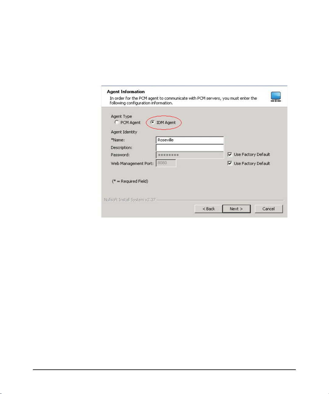
Figure 2-1. Agent Information
On the Agent Information window of the Agent Installation Wizard:
a. Select IDM Agent.
b. Type a Name and, optionally, a Description for the Agent.
c. The IDM Agent passwords for both server-initiated connections and agent-
initiated connections must match the password used for the PCM Server.
If the PCM Server uses the default password, select the Use Factory Default
check box. If the PCM Server uses a specific password, then clear the check
box and type the same password in the Password field.
d. If you do not want to use the default Web Management Port 8080, clear the
corresponding Use Factory Default check box and enter the web management port that will be used to authenticate with the PCM server.
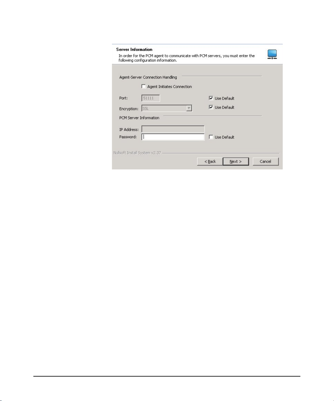
5. On the Server Information window, configure the Agent-server connection
settings and any required server information.
Page 19
Getting Started
Before You Begin
Figure 2-2. Server Information
For the Agent to communicate with the PCM server, these values MUST MATCH
the values set on the PCM server for this Agent.
a. If the Agent will initiate connection to the PCM server, select the Agent
Initiates Connection check box. If the PCM server will initiate a connection
to the Agent, ensure this check box is not checked.
All Agents that initiate connection to the PCM server must use the same
port number and encryption type as configured in the Agent Manager Server
Setup tab.
b. To change the default Port that the Agent will use to communicate with the
PCM server, clear the related Use Default check box and type the desired
port. The default PCM server port is 51111, which can be changed to any
unused port during PCM server installation or at the PCM server.
c. If you do not want to encrypt data sent to the PCM server, clear the related
Use Default check box and select Plain Text from the Encryption list. The
default encryption method is SSL. If the PCM server is behind a firewall,
HP recommends using SSL encryption.
d. In the IP Address field, type the IP address of the PCM server if the Agent
is initiating the connection to the PCM server.
2-3
Page 20

Getting Started
Before You Begin
e. To change the default Password that the Agent will use to communicate
with the PCM server, clear the related Use Default check box and type the
desired password. This must match the password set on the Agent Manager
Server Setup tab.
Once installed, the IDM Agent begins collecting User, Domain, and RADIUS data.
Installing on a Linux System
To install the IDM Agent on a supported Linux system:
1. Start a web browser, and type the IP address of the PCM server computer
followed by a colon and the port ID 8040. For example, if the IP address of the
server computer is 10.15.20.25, enter the following URL:
http://10.15.20.25:8040
2. From the list of available downloads, click IDM FreeRADIUS Agent and then
click Save to download the file.
3. Once the download completes, move the file to a location accessible by the target
Agent system, if necessary.
4. Extract the downloaded HpIdmLinuxAgentInstaller-<version>.tar.gz file to a
temporary location on the RADIUS server.
5. Change to the HpIdmLinuxAgentInstaller-<version> directory, run install.sh as
root, and then follow the prompts.
2-4
Checking IDM Server and Agent Connectivity
Check the Agent Status pane on the IDM Dashboard to verify that the IDM Server
and IDM Agent are installed and running. To do so:
1. From the bottom of the PCM navigation tree, select the Identity tab.
2. From the IDM navigation tree, select the Identity Management Home node.
3. In the right pane, select the Dashboard tab and review the Agent Status.
You can also check the Event Log for the RADIUS server for the event “RADIUS
server or Agent connected”.
Using the IDM Auto-Discover Feature
You can manually configure the RADIUS server, Domains, and Users in IDM, or
you can let IDM do the hard work for you. And, you have two options for automatically discovering users. Either enable Active Directory synchronization to import
users from the Active Directory, or install the IDM Agent on the system with the
Page 21

Getting Started
Before You Begin
RADIUS Server, then let it run to collect the information as users log into the network.
Even after you begin creating configurations in IDM, both options continue to collect
information on users and Domains (domains in Active Directory) and pass that
information to the IDM server.
If you are using multiple RADIUS servers, you need to install an IDM Agent on each
of the servers. The IDM Agent collects information only on the system where it is
installed. The IDM client can display information for all RADIUS servers where the
IDM Agent is installed.
When you start the IDM Client and expand the navigation tree in the IDM Dashboard
tab, you will see any discovered or defined Domains found on the RADIUS server,
along with the IP address for the RADIUS Server(s).
IDM Configuration Process Overview
To configure IDM to provide access control on your network, first let IDM run long
enough to “discover” the Domains, RADIUS servers, and users on your network.
Once IDM has performed these tasks for you, your configuration process would be
as follows:
1. If you intend to use them, define “locations” from which users will access the
network. A location may relate to port-based VLANS, or to all ports on a device.
(See page 3-5)
2. If you intend to use them, define “times” at which users are allowed or denied
access. This can be by day, week or even hour. (See page 3-12)
3. Define any network resources (systems and applications) that you want to
specifically allow or restrict users from accessing.
4. If you intend to restrict a user access to specific systems, you need to set the
User profile to include the MAC address for each system that the user is allowed
to login on. (See page 3-77.)
5. Create the Access Profiles, to set the VLAN, QoS, rate-limits (bandwidth)
attributes, and the network resources that are available, to users in an Access
Policy Group. (See page 3-32.)
6. Create an Access Policy Group, with rules containing the Location, Time,
System, and Access Profile that is applied to users when they login. (See page
3-42.)
OR
If using Active Directory synchronization, add rules and Access Profiles to the
Access Policy Groups automatically created by Active Directory synchronization.
2-5
Page 22

Getting Started
Before You Begin
7. If Active Directory synchronization is not used, assign Users to the appropriate
Access Policy Group. (See page 3-49).
8. If automatic deployment is disabled, deploy the configuration policies to the
IDM Agent on the RADIUS server. (See page 3-66)
9. Configure Auto-allow OUIs for the devices that will perform MAC authentica-
tion. (See page 3-54)
IDM Usage Strategies
You can use IDM to simply monitor user activity on the network, or to apply user
authentication rules to improve network security and performance. The following
table identifies the IDM configuration for various deployment and usage strategies
for IDM.
Table 2-1. IDM Deployment and Usage Strategies
Authorize
Authenticate
VLAN QoS Rate-
Limit
Network
Resources
x
xx
xx
xxx
xxxxx
Strategy Description
Monitors and reports user
activity.
Enhances normal RADIUS
authentication with Location,
Time, and System rules
Provides rudimentary VLAN
segregation (Unknown Users,
Guests, Visitors, Contractors)
Provides complete VLAN
placement for all Users
Provides QoS and Rate-limits per
User
Provides VLAN, QoS, and Ratelimit attributes, and accessibility
of defined Network Resources for
all users, based on Location, Time,
and System
2-6
Understanding the IDM Model
The first thing to understand is that IDM works within the general concept of
“domains.” Basically, domains are very large organizational units; every user belongs
to one, and only one, domain. While it is possible to have multiple domains, most
organizations have only one, for example, hp.com or csuchico.edu.
Page 23

Getting Started
Before You Begin
The basic operational model of IDM involves Users and Groups. Every User belongs
to a Group and, in IDM, these are called Access Policy Groups (APGs). Each APG
has an Access Policy defined for it, which governs the access rights that are applied
to its Users as they enter the network.
In the IDM GUI, the top level of the navigation tree is the Domain, with all other
information for APGs, and RADIUS Servers beneath the Domain in the navigation
tree. Users are linked to the Domain to which they belong, and the Access Policy
Group to which they are assigned.
The IDM configuration tools are available at the top level. The definition of times,
locations, network resources, and access profiles is independent of individual
Domains or Groups. You can define multiple locations, times, and network resources,
then create multiple access profiles to be applied to any Access Policy Group, in any
Domain that exists within IDM.
2-7
Page 24
Getting Started
IDM GUI Overview
IDM GUI Overview
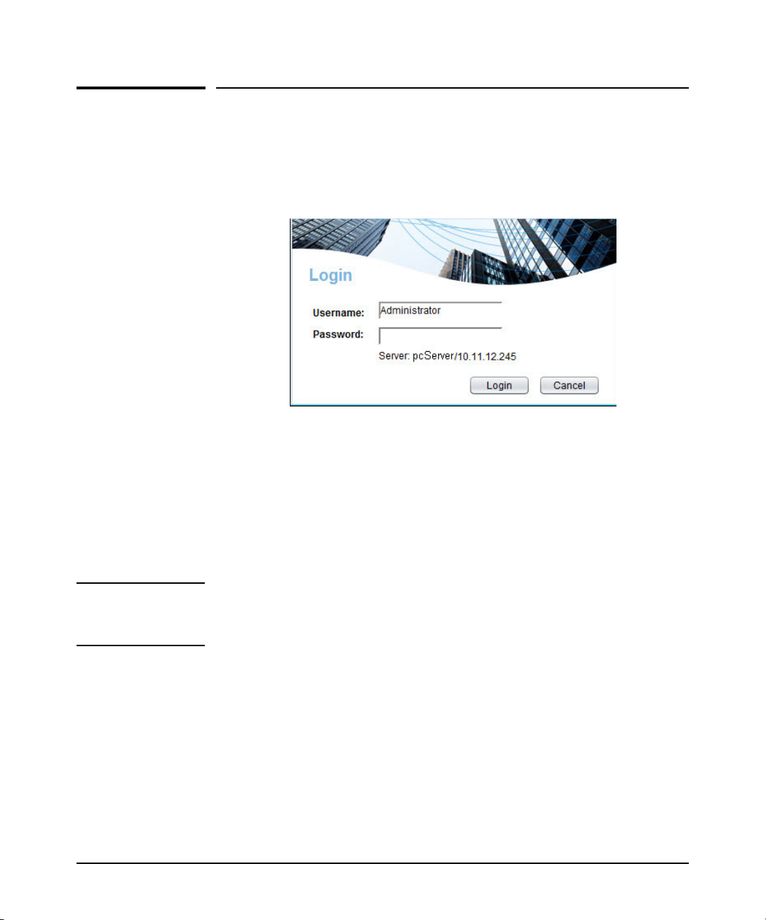
To use the IDM client, launch the PCM Client on your PC by selecting the PCM
option from the Windows Program menu. The PCM Client will start up and the Login
window will be launched.
Figure 2-3. PCM Login
If you did not enter a Username or Password during install, type in the default
Username, Administrator, then click Login.
For additional information on using the PCM Client, refer to the HP PCM+ 4.0
Network Administrator’s Guide.
Click the Identity tab at the bottom left of the PCM window to display the IDM
Dashboard.
Note: You can also access the IDM Dashboard by selecting the Network Management
Home node from the PCM navigation tree and clicking the Identity Driven Manager
tab at the top of the right pane.
2-8
Page 25
Getting Started
IDM GUI Overview
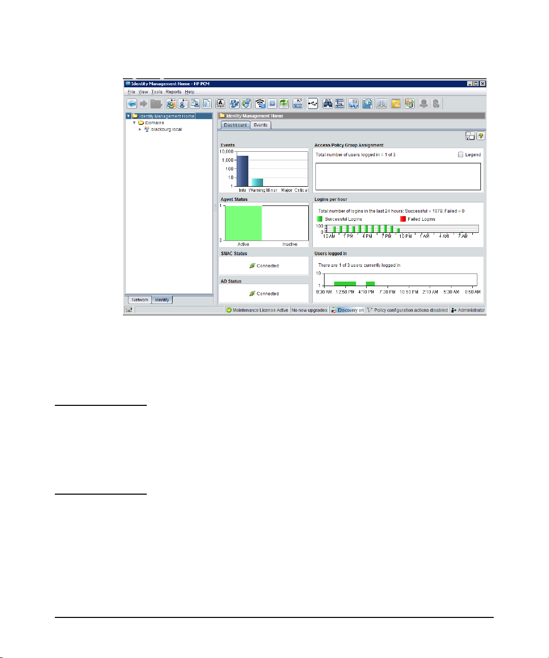
Figure 2-4. IDM Dashboard
The IDM initial display provides a quick view of IDM status in the Dashboard tab,
along with an Events tab, navigation tree, and access to menu and toolbar functions.
You can resize the entire window, and/or resize the panes (sub-windows) within the
Identity Management Home window frame.
Notes: If the IDM Dashboard shows the IDM Agent Status as inactive, and the Inventory
and Logins panes show no data:
■ Check the PCM Events tab for the following entry:
PCM remote client authentication failure: <ip address>
■ Check for IDM application events related to devices “supporting” or “not
supporting” the configuration.
2-9
Page 26

Getting Started
IDM GUI Overview
IDM Dashboard
The IDM Dashboard is a monitoring tool that provides a quick summary view of
IDM users, RADIUS servers, and events. The Dashboard can be viewed:
• From within PCM by selecting Network Management Home and clicking
the Identity Driven Manager tab.
• By clicking the Identity tab at the bottom of the PCM navigation tree.
The Dashboard tab contains the following panes of status information:
Table 2-2. IDM Dashboard Status Information
Pane Displays...
Events The total number of outstanding IDM events and the number of IDM
Access Policy Group
Assignment
Agent Status A color-coded graph showing the number of currently active and
Logins per Hour A scrolling 24-hour display that summarizes the total number of
SNAC status SNAC-IDM connection status
AD status IDM-AD connection status
Users Logged In A scrolling 24-hour display that shows the total number of users logged
events in each state. Clicking anywhere in the IDM Events pane or
clicking the Events tab displays the IDM Events window, which
contains detailed information about each event.
A pie chart showing the number of users assigned to each Access
Policy Group. Mousing over a section of this chart displays information
for the group and its users.
inactive IDM agents installed on RADIUS servers.
successful and failed IDM user logins at any given time during the past
24 hours. Information in this pane is updated every minute.
in at any given time during the past 24 hours. Information in this pane
is updated every minute.
2-10
Using the Navigation Tree
The navigation tree in the left pane of the IDM window provides access to IDM
features using the standard Windows file navigation system. Click the nodes to
expand the list and change the display in the right window pane.
Domains List
The top level of the tree lists each of the Domains that have been discovered by an
IDM Agent or defined manually. Clicking on the Domains node in the tree displays
the Domain List in the right pane of the window. Expanding the node displays each
Domain name in the tree, and assigned RADIUS Servers if they exist.
Page 27
Getting Started
IDM GUI Overview
Figure 2-5. Domain List tab
Domain Tabs
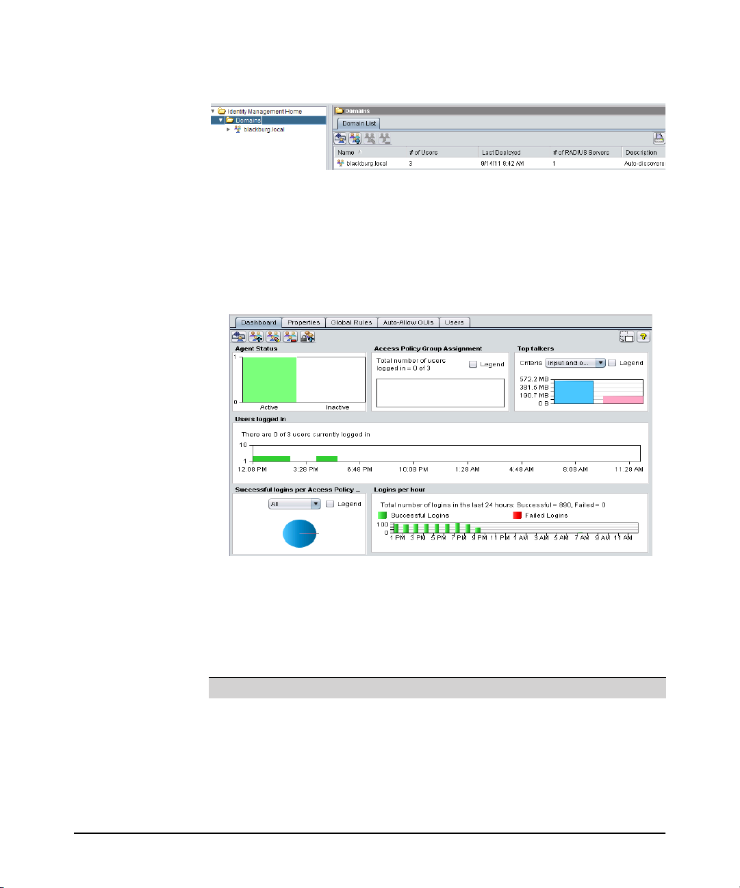
Expanding the Domains node and clicking a domain in the tree displays the Dash-
board tab in the right pane, along with the Properties, Global Rules, Auto-Allow OUIs
and Users tabs.
Figure 2-6. Domain - Dashboard tab
Domain Dashboard tab: The Domain Dashboard is a monitoring tool that provides
a quick summary view of IDM users and Agents. The Dashboard tab is similar to the
IDM Dashboard but contains statistics for the selected domain only.
Table 2-3. Domain Dashboard Status Information
Pane Displays...
Agent Status A color-coded graph showing the number of currently active and
Access Policy Group
Assignment
inactive IDM agents installed on RADIUS servers.
The number of users assigned to each Access Policy Group in the
domain and the total number of those users that are currently logged
in. You can hide the legend for this pane by clearing the Legend check
box.
2-11
Page 28
Getting Started
IDM GUI Overview
Table 2-3. Domain Dashboard Status Information (Continued)
Pane Displays...
Top talkers Input octets (bytes), output octets, or both. Use the list in this pane to
Users logged in A scrolling 24-hour display that shows the total number of users logged
Successful logins
per Access Policy
Logins per hour A scrolling 24-hour display that summarizes the total number of
select whether to display input octets, output octets, or both. You can
hide the legend for this pane by clearing the Legend check box.
in at any given time during the past 24 hours. Information in this pane
is updated every minute.
A pie chart showing the number of successful and failed IDM user
logins to each Access Policy Group during the selected time period.
Use the list in this pane to select the time period reflected in the chart.
Mousing over a section of this chart displays information for the group
and its users. You can also hide the legend for the chart by clearing the
Legend check box.
successful and failed IDM user logins at any given time during the past
24 hours. Information in this pane is updated every minute.
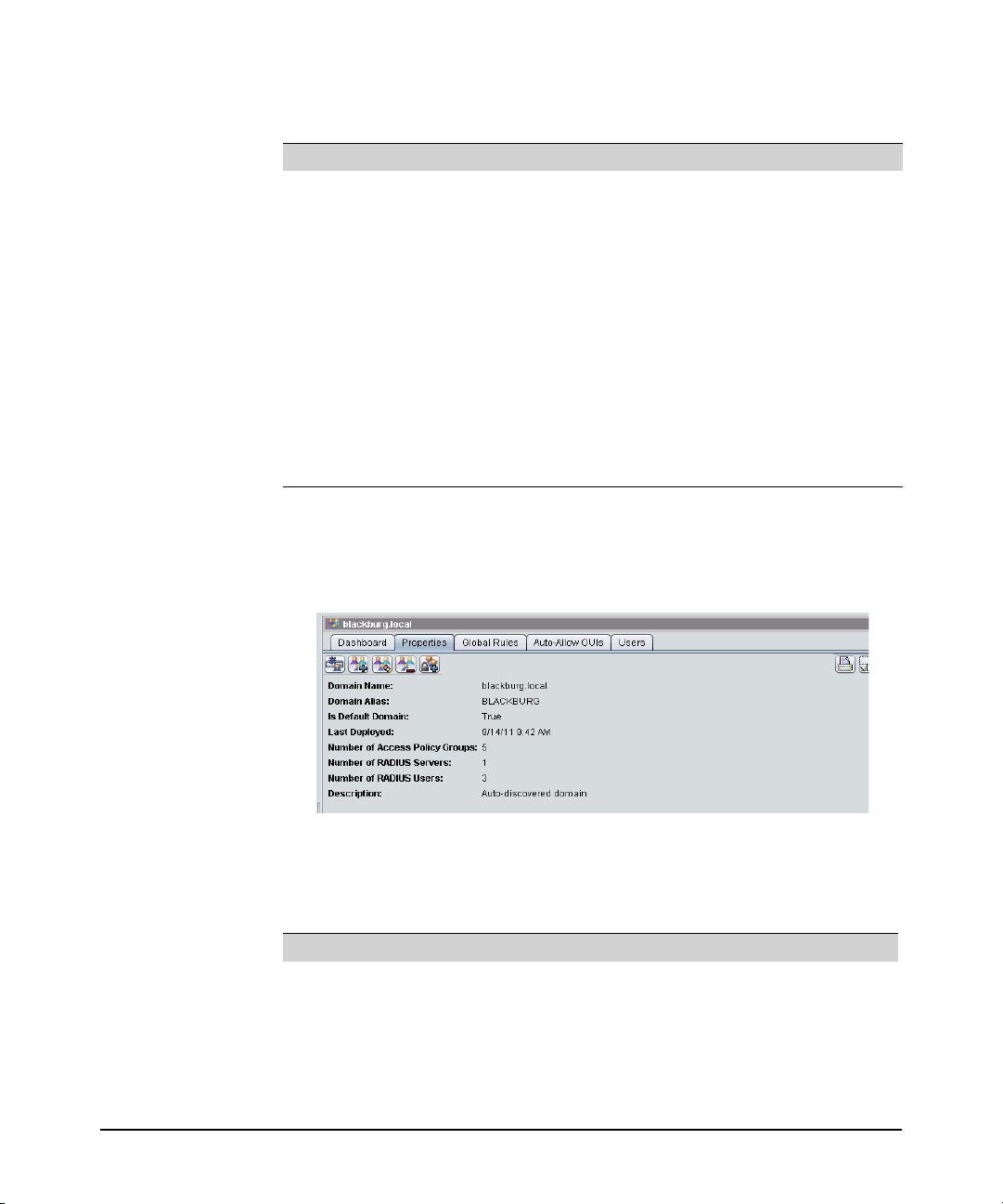
Domain Properties tab: Selecting an individual domain in the tree and then clicking
the Properties tab displays summary information about a Domain and its assignments. It also shows when the Domain was last deployed, which is especially useful
when you've made recent changes or are investigating IDM events.
2-12
Figure 2-7. Domain - Properties tab
The following information is shown on the Domain Properties tab:
Table 2-4. Domain Properties Information
Field Displays...
Domain Name Name used to identify the Domain
Domain Alias Alternate name for the Domain (usually the NETBIOS name)
Is Default Domain Whether the Domain is set as the default Domain: true means this
Domain is the default Domain and false means it is not. The default
Domain is used when IDM cannot determine the Domain for a RADIUS
server or user login.
Page 29

Getting Started
IDM GUI Overview
Table 2-4. Domain Properties Information (Continued)
Field Displays...
Last Deployed Date and time the policy was last deployed. Use this field to ensure
Number of Access
Policy Groups
Number of RADIUS
Servers
Number of RADIUS
Users
Description Brief description of the Domain
that the current Domain attributes have been deployed.
Total number of Access Policy Groups currently assigned to the
Domain
Total number of RADIUS servers assigned to the Domain
Total number of users assigned to Access Policy Groups used for the
Domain and currently logged in
Domain Global Rules tab: Clicking this tab displays rules that override Access
Policy Group rules and provides functions to configure and prioritize global rules.
See “Using Global Rules” on page 3-50.
Domain Auto-Allow OUIs tab: Clicking this tab displays automatic authentication
information for static devices based on their MAC address prefix (in addition to the
traditional authentication methods such as 802.1X Mac-Auth, and Web-Auth that
IDM supports).
Figure 2-8. Domain - Auto-Allow OUIs tab
Domain Users tab: Clicking this tab displays a list of users in the Domain that were
discovered by the IDM Agent, or defined manually. There are two additional columns
added to this tab for Device Type and another for User-Agent. By default, these
columns are not shown. These columns can be displayed by administrator.
2-13
Page 30

Getting Started
IDM GUI Overview
Figure 2-9. Domain Users tab
2-14
Expanding the Domain node in the tree will display the Access Policy Groups and
RADIUS server nodes for the Domain.
Filtering Support for Users tab:
Filtering functionality has been added to the users tab.Users can filter the table
content based on the following columns AuthID, Domain, Email, MAC Prefix,
Name, Owner and Phone.
Page 31

Getting Started
IDM GUI Overview
Access Policy Groups node
Clicking the Access Policy Group node displays the Access Policy Groups tab with
a list of currently configured groups. You can also expand the node to view the APGs
in the tree.
Figure 2-10. Access Policy Groups tab
2-15
Page 32
Getting Started
IDM GUI Overview
Click the individual group node in the navigation tree to display the group’s Dashboard, Properties, Auto-Allow OUIs and Users tabs. Information displayed for the
selected policy group is similar to the Domains tab displays described above.
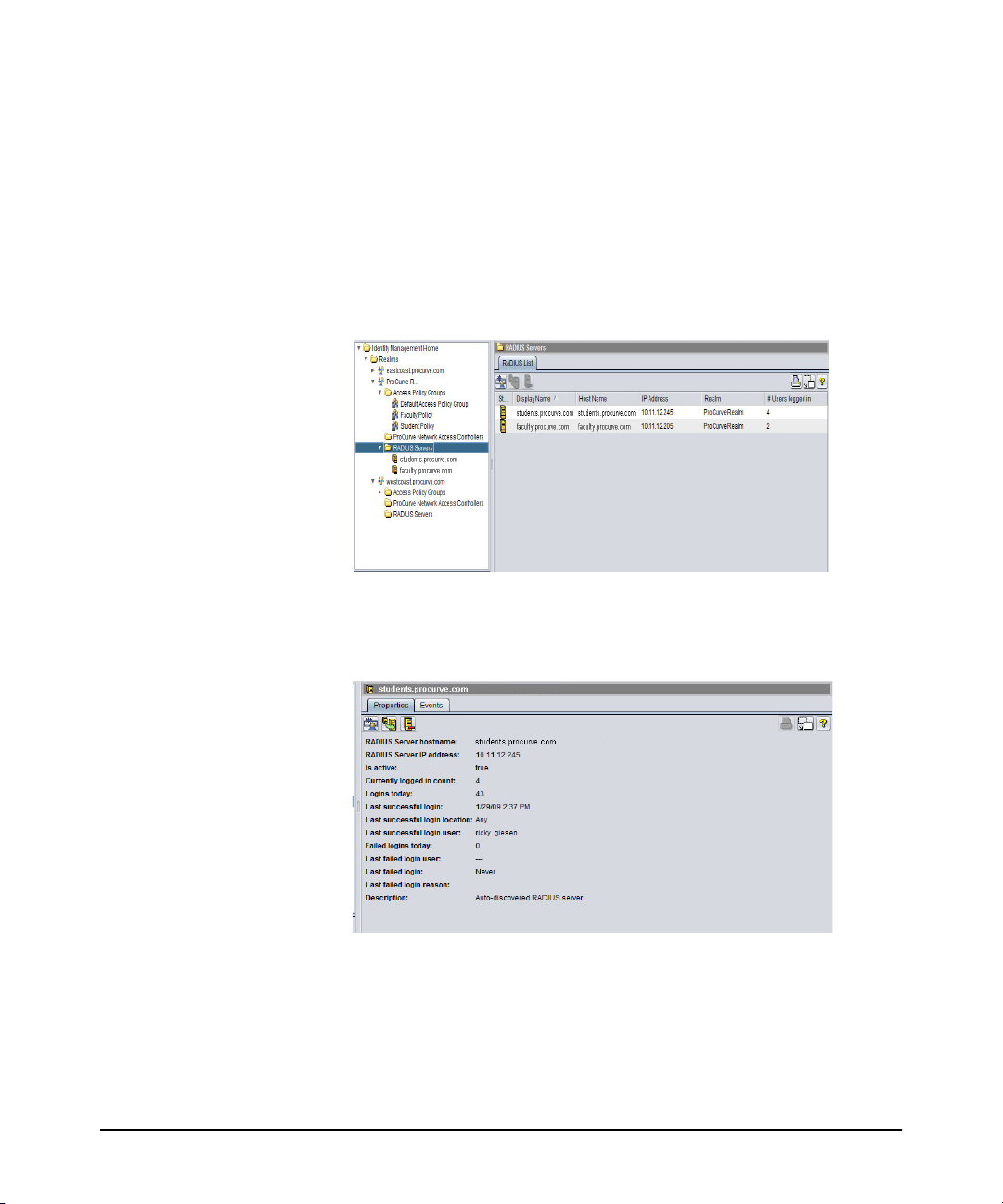
RADIUS Servers node
Clicking the RADIUS Servers node displays the RADIUS List tab, with status and
configuration information for each RADIUS Server in the Domain that has an IDM
Agent installed, or that is manually defined.
Figure 2-11. RADIUS List tab
2-16
You can expand the RADIUS Servers node to view the servers in the tree. Click the
individual server to display the RADIUS Server Properties.
Figure 2-12. RADIUS Server Properties tab
The Activity Log tab underneath the properties display contains a listing of IDM
application events for that RADIUS server such as server startup, server connections,
user logins, IDM configuration deployment, and so forth.
Page 33

Getting Started
IDM GUI Overview
Toolbars and Menus
Because IDM is a module within PCM+, it uses the same main menu and global
toolbar functions. Individual tabs or windows within the IDM module also include
separate component toolbars.
The functions available in the component toolbar vary based on applicable functions
for that component. Toolbar buttons for disabled functions are grayed out. The
component toolbar options are described under the process they support in the next
chapter. You can hover with the mouse to display “Tooltips” for each button.
Using Right-Click Menus
You can also access most of the functions provided with IDM via right-click menus.
To use the right-click menu, select an object (node) in the navigation tree on the left
of the screen, then right-click your mouse to display the menu. You can also access
right-click menus when an item is selected in a list on the tab window displays.
Figure 2-13. IDM Right-click menu
The options available in the right-click menu will vary based on the node or list item
you have selected. Disabled functions are greyed out.
2-17
Page 34

Getting Started
Using IDM as a Monitoring Tool
Using IDM as a Monitoring Tool
Whether or not you configure and apply access and authorization parameters using
IDM, you can use IDM to monitor user sessions on the network and generate usage
reports. You can use the monitoring features along with the IDM Reports to track
usage patterns, user session statistics, bandwidth usage, top users, and so on. The
User session information can also be used to track current user sessions and modify
the User’s access to network resources if needed.
Note: Session accounting must be enabled on switches, wireless controllers, and wireless
access points, as well as in IDM, for the monitoring and user session accounting to
work. Refer to the section on “Radius Authentication and Accounting” in the Access
and Security Guide provided with the PCM switch for details on enabling session
accounting.
You can enable or disable IDM monitoring using the IDM Preferences. Using the
IDM Preferences, you can also configure IDM to work with existing “Endpoint
Integrity” applications used to determine the compliance of the authenticating clients
to rules and requirements (for firewalls, anti-virus, and so forth) that have been set
up in the domain.
Note: If you are using Web-Auth or MAC-Auth for user authentication, user session
statistics are unavailable from the switch and cannot be collected, unless you are
using a version of firmware on the switch that supports accounting for Web-Auth and
MAC-Auth sessions. Not all switch software versions support this. Check the HP
Networking Support web site for updates.
2-18
Page 35

Getting Started
Using IDM Reports
Using IDM Reports
IDM provides reports designed to help you monitor and analyze usage patterns for
network resources. Report options are available from the Reports >User Access
Control menu at the top of the IDM main window.
The Report wizard screens and report parameters vary, depending on the type of
report selected. Selecting a report using the Reports >User Access Control list
launches the Report wizard, which you can use to set filter options, and selectable
data elements. When you click Finish, the report is generated and displayed, similar
to the following example:
Figure 2-14. IDM Configuration Report
You can save the report to a file, or print the report. To apply customized Report
Header information for your company, use the Reports option in global preferences
(Tools > Preferences > Reports). You can also schedule reports to be created at
recurring intervals by creating a policy with PCM’s policy manager, as described in
“Creating Report Policies” on page 2-22.
Each of the available reports is summarized below, along with the report filter options,
and configurable report parameters, if applicable.
Notes: You must have the Enable user session accounting option selected in IDM Prefer-
ences in order to collect bandwidth and other user session data for reports.
2-19
Page 36

Getting Started
Using IDM Reports
By default, all user history is reset and all session history is deleted by the predefined
IDM Session Cleanup policy on the first day of each month at midnight. However,
the IDM Session Cleanup policy can be modified to fit your needs.
The following IDM reports are available:
Table 2-5. IDM Reports
Report Contents
Configuration Detailed information for every Domain, RADIUS server, Access Policy Group,
Endpoint
Integrity
IDM Statistics Total hourly and daily logins and bandwidth usage during the reporting
and, optionally, user that the IDM agent has learned or that have been
defined in IDM. Domain information includes the most recent deployment
date and number of assigned users and RADIUS servers.
• The RADIUS server section includes the server name, whether the server
is currently active, number of successful and failed logins since midnight
of the current day, and number of Domains defined on the server (similar
to that shown on the RADIUS Server Properties window).
• The Access Policy Group section includes the Access Policy Group
name, number of Domains to which the Access Policy Group is assigned,
and number of users assigned to the Access Policy Group.
• The Users section shows the Domain and Access Policy Group to which
the user is assigned, username, date and time of last login, and input,
output, and total bytes used during the reporting period.
To collect report data, ensure the Identity Management Preferences are set
to enable user session accounting.
Whether a computer used to login is in compliance with corporate standards
monitored by a third-party endpoint integrity solution. If the RADIUS server
used to authenticate the user has a endpoint integrity solution, the computer
where the user logged in may be checked for integrity criteria such as upto-date anti-virus software and an authorized operating system. This report
is especially helpful in identifying computers that require anti-virus,
operating system, or other software installations/updates.
period. This report is especially helpful in identifying access profiles that
require bandwidth adjustment and hardware components that require
maintenance.
2-20
Page 37

Getting Started
Using IDM Reports
Table 2-5. IDM Reports (Continued)
Report Contents
Session
History Details
Unsuccessful
Logins
User
Bandwidth
Usage
User MAC
Addresses
User Report Information for recent sessions in which the user participated, similar to the
Detailed information about all login attempts, whether successful or failed.
This report is especially helpful in identifying login failures and whether an
access profile, location, or user needs to be modified in PCM.
Once the initial report dates and filters are set, you can also configure what
columns you want to include in the report. The available column headings
include:
• RADIUS Server IP
• Location
• MAC Address
• Device
• Device Port
• VLAN
• QOS
• Endpoint Integrity State
Failed system logins, which can be filtered by date.
Summary of system usage by users. This report can include all users or be
limited to only the top bandwidth users during the reporting period. This
report is especially helpful in identifying candidates for throttling.
MAC address of every computer from which the user logged in during the
report period. This report is especially helpful when setting up login
restrictions and for accounting purposes.
Session History report.
To display the User Report select a username in the Users tab of the Access
Policy Group or RADIUS Server window, and then click the Show User
Report button in the toolbar.
2-21
Page 38

Getting Started
Creating Report Policies
Creating Report Policies
You can also use the Policy Manager feature to schedule reports to be created at
regular intervals, or in response to an event. For complete details on creating policies,
refer to “Configuring Policies” in the HP PCM Network Administrator’s Guide.
The basic process for creating a Report Policy is:
■ Time - Configure the Time periods when the report policy can be executed.
If no time is specified, the policy can execute at any time.
■ Alerts - Use the Scheduled Alert option to set a recurring schedule for a
report to be generated. Alerts serve as the trigger used to launch an Action.
Alerts can be event-driven, or scheduled to occur at a specified time.
■ Action - Configure the Report Manager:GenerateReport type(s) for the
policy. The following section describes the Report action types and configurable parameters and filters for each report type.
You do not need to configure the Sources or Targets for a Report Policy, since you
will select the device groups the policy applies to in the Report Action.
2-22
Configuring a Policy Action to Generate Reports
To configure a Policy Action to run a report:
1. Click the Policy Manager button in the toolbar,
OR
Select Tools > Policy Manager to launch the Policy Configuration Manager
window.
2. Click the Actions node in the Policy Manager window to display the Manage
Actions pane.
Page 39

Creating Report Policies
Getting Started
Figure 2-15. Policy Manager, Actions
The Manage Actions window displays the list of defined Actions.
3. Click New to launch the Create Action dialog.
Figure 2-16. Policy Manager, Create Action
2-23
Page 40
Getting Started
Creating Report Policies
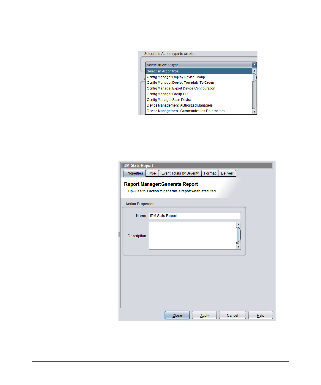
4. Select the Report Manager:Generate Report Action type from the menu.
Figure 2-17. Policy Manager, Select Action
5. Type a Name for the Action (required) and a brief Description (optional).
6. Click OK to save the Action and display the Action Properties tab.
The properties you set in the previous step will display.
2-24
Figure 2-18. Policy Manager: Report Manager Action configuration
Page 41

Creating Report Policies
Getting Started
At this point the other tabs displayed are:
Type: Lets you select the Report type you want to generate. As soon as you
select a report type, additional tabs may appear in the window depending
on the filter criteria for the report
Format: Lets you set the report output format
Delivery: Lets you select where the report will be sent (to file, e-mail, and
so forth)
7. Click the Type tab and select the IDM Report type you want included in the
action. In this example, a Network Activity report is selected, so corresponding
report filter tabs will be added to the window.
Figure 2-19. Report Manager Action, Report Type selection
8. Click a report filter tab to select the report criteria to be applied when generating
the report. The filter options will vary based on the selected report.
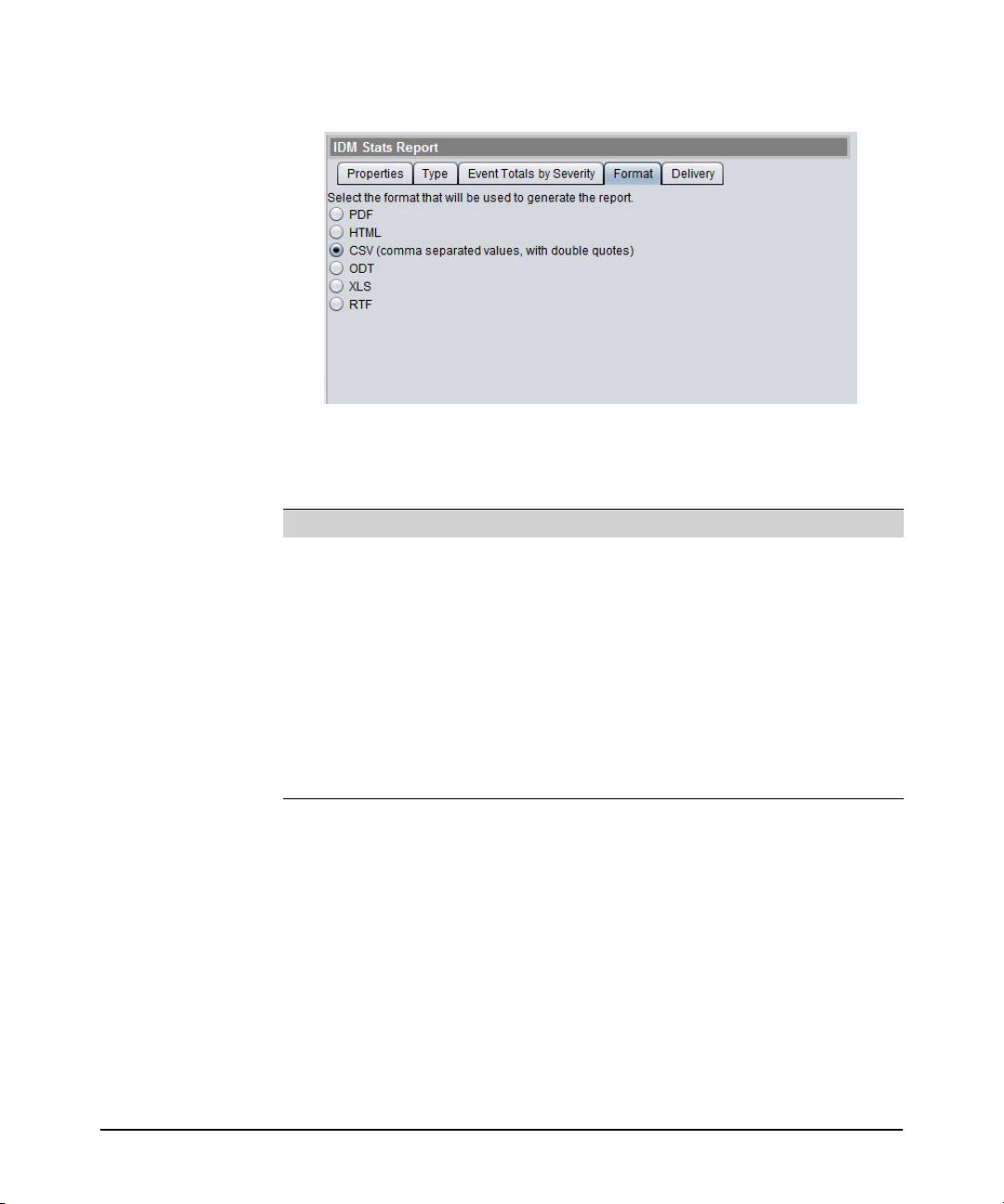
9. Click the Format tab.
2-25
Page 42
Getting Started
Creating Report Policies
Figure 2-20. Report Manager Action: Report format selection
10. Select how you want to generate the report for the following options.
Table 2-6. IDM Status Report Options
Select... To produce the report...
PDF In.pdf format. To view this file format, you will need Adobe Acrobat
HTML
CSV Using comma separated values with double quotes. This report can be
ODT In Open Office .odt format.
XLS In.xls format, which can be viewed in MS Excel spreadsheets.
RTF In.rtf format, which can be viewed in most word processing
Reader, which can be downloaded free from http://get.adobe.com/
reader.
In.html format, which can be viewed with any Web browser.
viewed using WordPad, Notepad, or imported into other spreadsheet
programs, such as Excel.
applications.
2-26
11. Click the Delivery tab to configure the method used to deliver the report.
Page 43

Creating Report Policies
Getting Started
Figure 2-21. Report Manager Action: Report Delivery method
Email is the default method. It will email the report to the address specified. It
also requires that you have an SMTP profile for the email address. See “Creating
SMTP Profiles” in the HP PCM+ 4.0 Network Administrator’s Guide for details.
Use the menu to select a different delivery method.
Figure 2-22. Report Manager Action: Select Delivery Method
Selecting FTP as the delivery method lets you save the report on an FTP site.
However, proxy support is not provided.
a. In the FTP Server field, type the IP address of the FTP site where you want
to save the report.
b. In the Path field, type the complete path to the server location where you
want to save the report.
c. In the Filename field, type the filename you want to assign to the report.
You can automatically add a timestamp to the filename in the Filename
conventions pane.
d. In the Username field, type the username used to access the FTP site.
2-27
Page 44

Getting Started
Creating Report Policies
e. In the Password field, type the password used to access the FTP site.
f. Select the Filename conventions to use:
– No timestamp in file name: Name the file exactly as entered in the
Filename field.
– Prepend timestamp to file name: Add the timestamp at the beginning
of the filename entered in the Filename field.
– Append timestamp to file name: Add the timestamp at the end of the
filename entered in the Filename field.
Selecting File as the delivery method lets you save the report in a file on the PCM
server.
a. In the Path field, type the complete path to the server location where you
want to save the report.
The path is relative to the server (not to the client). To save the report on
the client, there must be a path from the server to the client. For example,
use UNC paths, since the server runs as a service and cannot be set up easily
to use mapped drives.
b. In the Filename field, type the filename you want to assign to the report.
c. Select the Filename conventions to use, as described above for FTP files.
12. Click Apply to save the Action Configuration.
13. Click Close to exit the Policy Manager window.
If you click Close before you click Apply, you will be prompted to save or discard
the configuration.
Note: Report output is limited to 40 pages. Therefore, to create a report on many (1000+)
items, you need to create separate reports to generate all the data.
You can access User Reports by right-clicking the user in the Users tab display in
IDM and then selecting the report option.
IDM Session Cleanup Policy
The IDM Session Cleanup Policy is included in the PCM policies by default when
you install IDM. The report statistics IDM reports are cleared by the Session Statistics
Cleanup policy (in PCM) on the first day of each month. A special IDM Session
Cleanup alert is used to define the schedule for the policy. You can edit the policy
(alert) if you want to change the cleanup recurrence schedule.
To modify the IDM Session Cleanup Alert:
2-28
Page 45
Creating Report Policies
Getting Started
1. Click the Policy Manager button in the toolbar.
OR
Select Tools > Policy Manager to launch the Policy Configuration Manager
window.
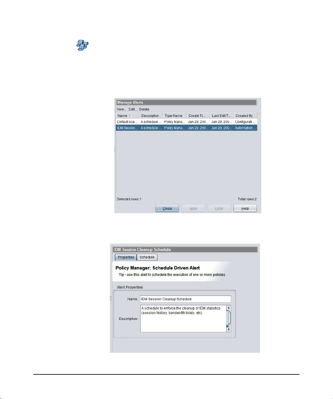
2. Select the Alerts node from the navigation tree to display the Manage Alerts
pane.
Figure 2-23. Manage Alerts: IDM Session Cleanup selection
3. Select the IDM Session Cleanup policy and click Edit to display the properties.
Figure 2-24. IDM Session Cleanup Schedule properties
2-29
Page 46
Getting Started
Creating Report Policies
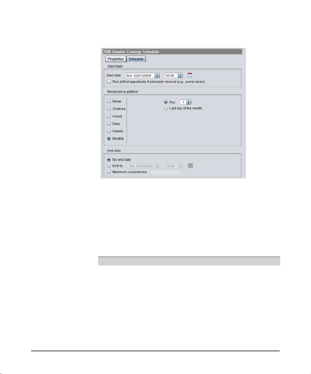
4. Click the Schedule tab to review and edit the schedule parameters.
Figure 2-25. IDM Session Cleanup Schedule, alert configuration
5. Set the Start Date for enforcement of the policy. The default is the start date and
time for IDM. You can type in a new date and time, or use the arrows to increase
or decrease the date and time entries. Note that the time clock uses 24 hour
format; thus a time of 22:00 is used to indicate a start time of 10:00 pm.
To trigger the IDM Session Cleanup policy to run immediately, select the check
box for Run at first opportunity if schedule missed.
6. You can change the session cleanup interval using the Recurrence pattern
options:
To select... Do this...
Never No further action is required (Policy definition is saved, but will not be
One time No further action is required (the currently scheduled time is used with
Hourly Type the number of hours and minutes to wait between session
Daily Type the number of days to wait between session cleanups. If you do
enforced).
no recurrences).
cleanup. If you do not want the policy enforced on Saturdays and
Sundays, select the Skip weekend check box.
not want the policy enforced on Saturdays and Sundays, select the
Skip weekend check box.
2-30
Page 47

Creating Report Policies
To select... Do this...
Weekly Select the check boxes for the days of the week you want to enforce
the policy.
Monthly Select Last day of the month to enforce the schedule on the last day of
the month.
OR
Select Day and use the up or down arrows to select the day of the
month.
Getting Started
7. Use the radio buttons to select No end date, End by, or Maximum occurrences to
identify when the schedule should end.
• If you select No end date, the schedule will run at the selected intervals until
the policy is changed or deleted.
• If you selected End by, use the up and down arrows in the field until the
desired end date and time are shown.
• If you selected Maximum occurrences, type the number of times the policy
should be enforced before it is disabled automatically.
8. Click Apply to save the changes, then Close to exit the alert configuration.
2-31
Page 48
Getting Started
Monitoring User Session Information
Monitoring User Session Information
You can use IDM to just monitor the network, and receive detailed information about
user's access to the network. User Session information provides statistics about
exactly how the network is being used (when the user logged in and out, where a user
logged in from, and how much bandwidth they consumed, for example). Based on
the User Session information, you can adjust access rights for users, further restricting
or providing additional network resources and access attributes as needed.
To review user session information:
1. Navigate to the user’s Domain and click the Users tab.
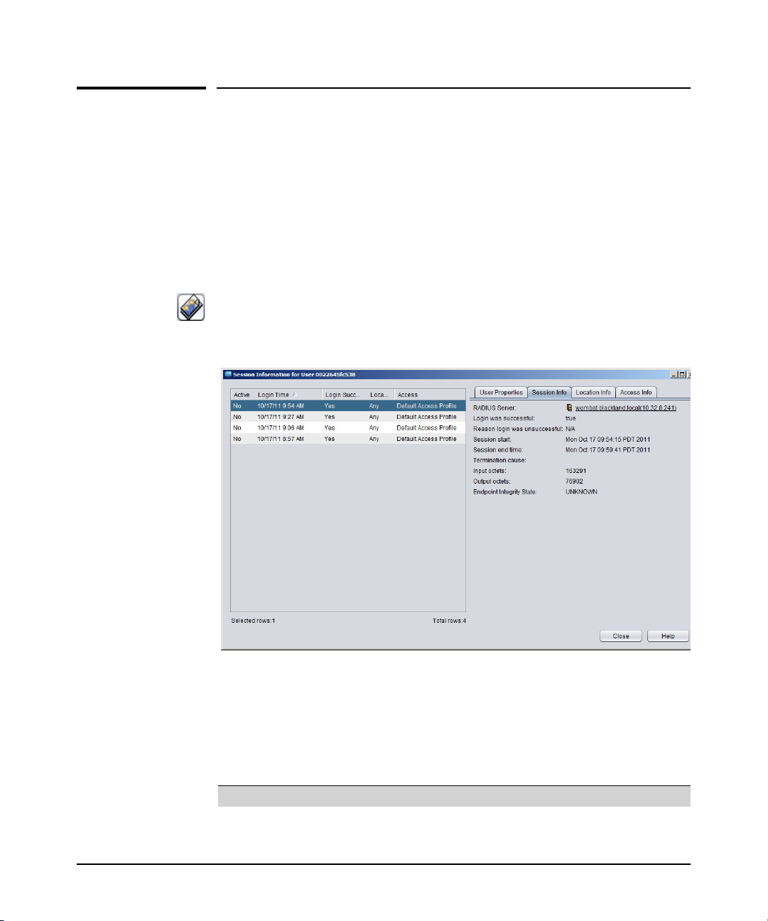
2. Click the Show the User’s session status button in the Users tab toolbar to display
the Session Information window.
2-32
Figure 2-26. IDM User Session Information
The list in the right pane of the Session Information window shows recent sessions,
including the following information:
Column Displays...
Active Yes if the user is currently logged in for this session or No if the
session has ended
Page 49

Monitoring User Session Information
Column Displays...
Login Time The date and time the user logged in
Login Successful Yes if the user logged in successfully or No if login failed
Location The name of the location where the user logged in
Access The access profile assigned to the access policy group governing
the user’s permissions during the session
Getting Started
3. Click the User Properties tab to view the following information:
Field Displays...
Domain The domain to which the user is currently assigned
Auth ID The ID given to user’s login account
Name The name of the user
MAC Address The MAC address of the computer where the user logged in
IP Address The IP address of the computer where the user logged in.
Is active Yes if the user is currently logged in for this session or No if the
Last login time The date and time of the most recent user login
Login Count The total number of times the user logged in during the report
This field will only appear if DHCP snooping is enabled for the
VLAN of which the client is a member, and may take some time
to populate.
session has ended
period.
4. Click the Session Info tab to view the following information:
Field Displays...
RADIUS Server The IP address of the RADIUS server that authenticated the
Login was successful Yes if the user logged in successfully or No if login failed
Reason login was
unsuccessful
Session start The date and time the user logged in
Session end time The date and time the user logged out or the session was ended
Termination cause The reason the RADIUS server ended the session (for example,
Input octets The number of bytes received by the user during the session
Output octets The number of bytes sent by the user during the session
user
If the login was unsuccessful, the reason the RADIUS server
or IDM denied the login (for example, access policy group not
found for user or username/password incorrect)
user logout, connection interruption, or idle timer expiration)
2-33
Page 50

Getting Started
Monitoring User Session Information
Field Displays...
Endpoint Integrity State If endpoint integrity is enabled. whether the user must pass
5. Click the Location Info tab to view the following information:
Field Displays...
Location name The name of the location where the user logged in
Device address The IP address of the device used to login
Ethernet port The port on the device used for the session
BSSID The MAC address used for wireless device
SSID The SSID in packets associated with the user
a. Click the Disable Ethernet or Enable Ethernet links to disable or re-enable
6. Click the Access Info tab to view the following information:
endpoint integrity requirements before they can log into the
network
the port used for the session. For example, if you want to prevent the user
from logging in at a specific device or force the user to re-authenticate, you
would use the Disable Ethernet function. If you need to re-enable the port
so the user can resume the session, use the Enable Ethernet function.
Field Displays...
Access Policy Group The access policy group that governs user permissions for the
Access Profile The access profile assigned to the access policy group.
QoS assigned The Quality of Service or priority for outbound traffic. QoS
Ingress rate limit The maximum bandwidth for inbound traffic to allocated to user
Egress rate limit The maximum bandwidth for outbound traffic to allocated to
Untagged VLAN The untagged VLAN to which access is given.
Tagged VLANs The tagged VLAN to which access is given
ACL The access control rules that were applied to the user's
session.
ranges from lowest to highest.
by the access profile
user by the access profile
DEFAULT_VLAN(1) is equivalent to allowing access on the
entire network.
session on the switch or access point
2-34
Page 51

Monitoring User Session Information
Getting Started
Find User Session
The Find User Session feature let you search and display information about a user
session by Auth ID or MAC address. The displayed information is similar to User
Session Status information. This information contains all the session history records
associated with a given Auth ID or MAC address.
If the specified Auth ID or the MAC address does not have session records in the
session history, then it returns an empty result set.
Note: If you want to know the devices that are registered by a given user/guest or search
by Auth ID, then you may use filter feature provided at the Users tab view available
at domain as well as APG node level.
To find information for Auth ID or MAC address:
1. From the IDM navigation tree, right-click the Domains or Access Policy Groups
node to which the user or computer is assigned and then select Find User Session
from the right-click menu.
This launches the Find User Session window.
2-35
Page 52
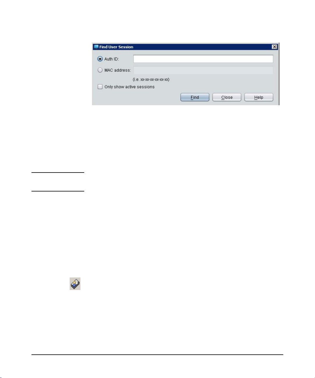
Getting Started
Monitoring User Session Information
Figure 2-27. Find User Session
2. In the Auth ID field, type the complete Auth ID that you want to find.
OR
In the MAC address field, type the MAC address of the computer for which you want
to find and display information.The MAC address may be specified in any valid
standard format (single dash, multi-dash, multi-colon, no delimiter, etc.) in Auth ID
or MAC address fields.
Note: The Find User Session functionality returns the Session History records for the user
matching the Auth ID/MAC Address for all active and inactive sessions.
2-36
3. Select the Only show active sessions check box to get only the information on
active sessions for the user.
4. Click Find to display information for the specified user session or computer.
5. Click Close to exit the window.
User Reports
To review information for multiple sessions, run the User Report:
1. Select a username in the IDM Users tab.
2. Click the Show User Report button in the toolbar. This launches the Report
Wizard, Report Filter window.
Page 53

Monitoring User Session Information
Getting Started
Figure 2-28. Report Wizard, Report Filter
3. To report on a specific time range, clear the All Dates (no filter) check box and
select the Start Date and End Date. Click Next to select the report contents.
2-37
Page 54

Getting Started
Monitoring User Session Information
Figure 2-29. Report Wizard, Columns to Include
4. Select the check boxes to select the data columns. If wireless settings are enabled
the WLAN and BSSID options also appear.
5. Click Finish to run the report.
The report is displayed in a separate window on the IDM Client.
Show Mitigations
The Show Mitigations window lists all NIM mitigations (actions taken to resolve
security threats) for the selected user and is used to delete NIM mitigation rules.
Mitigation can include prohibiting user login or limiting user capabilities by VLAN
restrictions, rate limiting, Quality of Service (QoS), and so forth.
Rules can also be rolled back with NIM mitigation policies. However, if a rollback
timer has not been defined for the policy, the IDM mitigation rules are permanent
and must be deleted through the Mitigations window.
2-38
Page 55
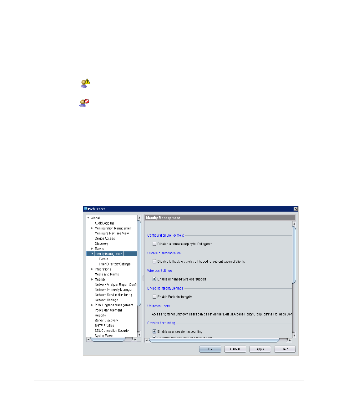
Monitoring User Session Information
To show or delete mitigations:
1. In the IDM Users tab, right-click a mitigated user and choose Show mitigations
to display the Mitigations window. This function is selectable for mitigated users
only. Mitigated users are identified by one of the following buttons:
User successfully logged in, but the session was mitigated in some way (for
example, VLAN, rate limit, QoS)
User login was prohibited by NIM mitigation action
The Mitigations window lists each rule associated with the selected user and all
MAC addresses where the user has logged in.
2. To delete a single rule, select the rules to delete and click Revoke.
3. To delete all rules, click Select All and then click Revoke.
Getting Started
IDM Preferences
The IDM Preferences window is used to set up global attributes for session
accounting and archiving, as well as to enable the Endpoint Integrity option.
Select Tools > Preferences > Identity Management to display the Preferences,
Identity Management window.
Figure 2-30. Preferences - Identity Management
2-39
Page 56

Getting Started
Monitoring User Session Information
Click the option check boxes to select (check) or deselect (clear) the following
options.
1. Select the Configuration Deployment option to automatically deploy IDM
configuration settings (Access Profiles, Locations, Times, Network Resources)
to the IDM agent. The default preference is to allow automatic configuration
deployment.
Select the Disable automatic deploy to IDM agents option if you do not want to
use automatic IDM configuration deployment.
If you “disable” the Configuration Deployment option. in order for IDM configuration changes to take affect you will need to manually deploy the configuration
to the IDM agent(s).
2. Select the Client Re-authentication option to automatically trigger re-authentication of clients upon registration, based solely on the port to which they are
connected. Enabling this option should be done with care as multiple clients can
be connected to a port at a time. Re-authentication is first triggered based on the
port and MAC address of the client. In case of failure and if this option is not
disabled, re-authentication will be triggered based on only the port to which the
client is connected.
3. Select the Wireless Settings option to allow configuration of Identity Management features for select PCM wireless devices. The default preference has the
Enable enhanced wireless support option checked. When this option is
unchecked, wireless configuration options will not be visible and will not be
applicable in rule evaluation.
4. Select the Enable Endpoint Integrity option to enable endpoint integrity in the
Access Rules definitions, allowing you to configure an Access Rule with one of
the Endpoint Integrity options (Pass, Fail or ANY). When you enable Endpoint
Integrity and set the attribute in a Global Access Rule or Access Policy Group
rule, the IDM agent will look for the RADIUS attribute in the supplicant’s
authentication request and act accordingly, applying the defined access rule
based on the endpoint integrity system response.
5. Select the Enable User session accounting option to collect information about
user logins and logouts. This must be selected if you want to collect data for user
logins and bandwidth usage, which is used for the Bandwidth, Session, and User
reports.
6. To generate user session start and stop events and display them in the IDM Events
list, select the Generate Session Start and Stop Events check box. This option
does not affect accounting or collection of session history and statistical information. Turning this option off will reduce the load on your IDM server and the
GUI by eliminating two-thirds of the events created for every user login and
logout.
2-40
Page 57

Monitoring User Session Information
Getting Started
7. To reset all session accounting information whenever the server is restarted,
select the Reset accounting statistics when the management server starts check
box. When this option is selected, IDM closes any open sessions and resets the
RADIUS Server totals to zero when the server restarts.
If the status of users—logged on or off—seems incorrect, it is possible that the
session accounting is out of sync. Use the Reset accounting statistics option to
correct the problem. This immediately closes any open sessions (this has no effect
on the user, only on the IDM accounting), and resets user login counts on the
RADIUS server to zero.
Existing accounting records are not removed by the Reset procedures, the only
effect is that currently open sessions are closed.
8. To ignore capability override warnings generated by switches that don't support
certain capabilities (for example, VLAN, QoS, Bandwidth, and ACL overrides),
select the Ignore device capability warnings check box.
9. To send only those attributes supported by the device, select the Only send
supported device attributes to device check box.
10. If you wish to archive accounting records older than a specified time period,
clear the Disable session archiving check box, and set the desired archival time
period in the Archive user sessions older than x days field.
If using SNAC for a network with a moderate number of logins (for example,
20,000 logins per day), HP recommends that you enable session archiving (clear
the Disable session archiving check box). This volume will not compromise the
responsiveness of IDM operations.
11. To archive the user session archive file in a location other than the default IDM
data archive directory, type the desired path in the Archive file directory field.
The default path is:
C:\Program Files\Hewlett-Packard\PNM\server\idm\data
12. If you do not want to add a timestamp to the archive filename, clear the Use
timestamp in archive filename option.
If a timestamp is not used in the archive filename, the existing archive file is
overwritten each time user sessions are archived.
a. To insert a timestamp in the front of the archive filename, select the Prepend
timestamp to archive filename option.
b. To add a timestamp to the end of the archive filename, select the Append
timestamp to archive filename option.
13. Click OK to save your changes and exit the window.
Click Apply to save your changes and leave the Preferences window open.
Click Cancel to close the window without saving changes.
2-41
Page 58

Getting Started
Monitoring User Session Information
Using Active Directory Synchronization
The Active Directory Synchronization (AD Sync) feature provides the ability to
receive change notifications from the active directory server for the domain the
management server is logged into. Active Directory Synchronization will automatically update the IDM database with changes made in your Active Directory, including
new users, changes to existing users, and deletion of users.
Notes: ■ AD Sync must be enabled on the IDM server and proper groups must be
synchronized. Otherwise, the default Access Policy Group is used.
■ The User/IDM Import Wizard does not work with SNAC.
To configure AD Synchronization (AD Sync):
1. From the PCM global menu, select Tools > Preferences.
2-42
Page 59

Monitoring User Session Information
Getting Started
Figure 2-31. Identity Management Preferences: User Directory Settings
2. In the left pane of the Preferences window, expand Identity Management and
select User Directory Settings.
3. In the Identify Management: User Directory Settings pane, select the Enable
automatic Active Directory synchronization check box and type the Username
and Password of the Active Directory to be synchronized.
Although the figure above shows an example of an “administrator” user being
created, it is a good idea to select a user with less privileges since, in that case,
a domain admin account will not be needed. Ideally a user should be created for
“List contents permission and for SNAC configuration.
4. Check that the Domain field displays the domain in which the user will log into
the SNAC Registration Server and on which IDM is listening for AD updates.
If this field is not automatically displaying a domain name, there may be a
problem with the DNS service or DNS Server configuration on your system. AD
sync will not work if this field is empty.
5. In the Domain Controller(s) field, enter host names or IP addresses (separated by
a space) of domain controllers for this user group. Using more than one is
recommended for redundancy.
6. Click Add/Remove.
2-43
Page 60
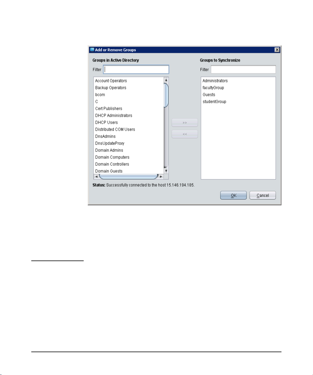
Getting Started
Monitoring User Session Information
Figure 2-32. Add/Review AD Groups to Synchronize
The Active Directory is queried for all groups in the domain and the groups are
displayed in the Groups in Active Directory list.
Note: When adding or removing groups remember that synchronization includes all
users who are indirect members of a group via intervening nested group relationships. In addition, users belonging to more than one AD group are added to the
IDM group with the higher priority. For example, User 1 in the following example
is imported into Group ALL if IDM synchronizes on Group ALL. Or, if IDM
2-44
Page 61
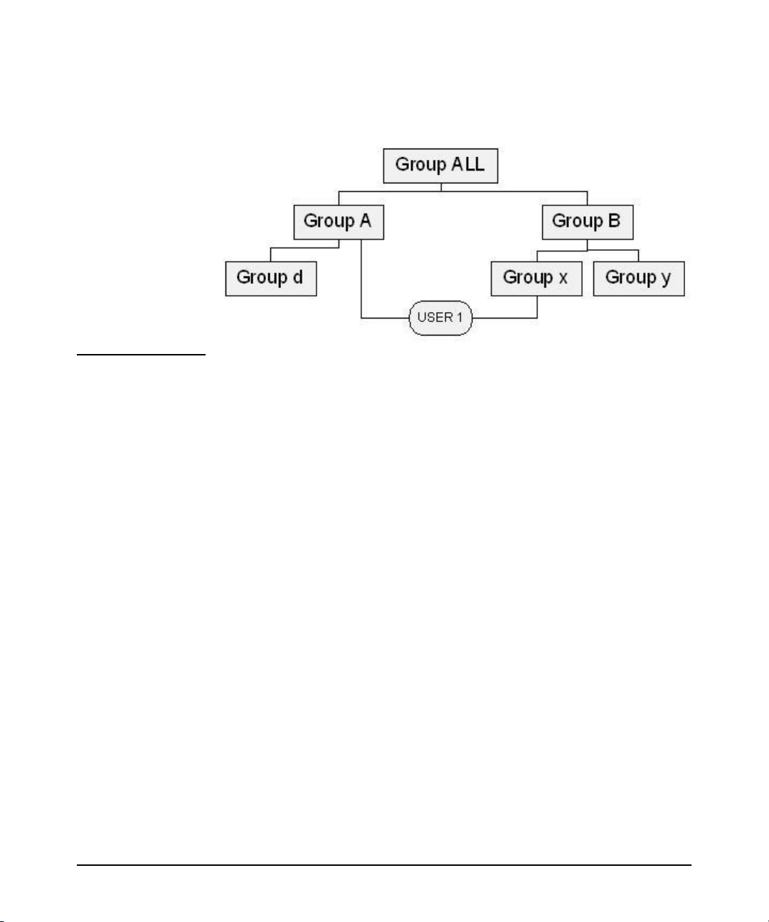
Monitoring User Session Information
Getting Started
synchronizes on Group A or Group B, User 1 is imported into the group with the
higher priority. If IDM synchronizes on Group d or Group y, the User 1 is not
imported.
7. On the Add or Remove Groups window, select the groups to sync in the Groups
in Active Directory column and click the >> button to move them to the Groups
to Synchronize column.
8. When you have selected all the groups you want to sync, click OK.
9. On the User Directory Settings window, for each group that you have added,
select whether users should be imported from AD into the IDM database. Select:
• Yes to import users, such as 802.1X or hybrid users
OR
• No (SNAC Only) to not import SNAC users. SNAC users will not be imported
since they are added to the IDM database when they register for SNAC
10. Click Move Up and/or Move Down to set the priority that IDM uses to apply the
access level. If a user is in multiple groups in AD, IDM uses this list to determine
which group’s access level to apply to the user. The access profile that is applied
to the user is the one for the group that is the highest in the list.
11. When you have finished making the changes, click:
• Apply to apply the changes and keep the window open. The status of the
changes is displayed in the AD Status area. You may see a message such as
Connected.. Imported 50 users. When the changes are complete, the Listening for updates message is redisplayed.
OR
• OK to apply your changes and close the window.
2-45
Page 62

Getting Started
Monitoring User Session Information
12. An Importing Users dialog box will display the number of users being imported
and a progress bar indicating how long the process is taking. When you are done
monitoring the progress of your import, click Close.
If you are importing users from AD into the IDM database instead of using SNAC,
an Access Policy Group is created for each selected Active Directory group, and
all users that belong to the selected groups will be imported from the Active
Directory server into the appropriate Access Policy Group. Changes to users in
the selected groups will be imported (synchronized) as long as the Active
Directory Synchronization is enabled.
The Importing Users dialog closes automatically when the synchronization is
complete and the Preferences window remains open.
Operating Notes:
■ If a user belongs to more than one Active Directory group, the user is
imported into the IDM Access Policy Group with the highest priority (set
in User Directory Settings Preferences).
■ If an Active Directory group is deleted while Active Directory synchroni-
zation is enabled, the associated Access Policy Group is deleted. If that
group is the priority IDM Access Policy Group for a user who belongs to
more than one Active Directory group, the user is automatically reassigned
to the next highest priority Access Policy Group. Users who do not belong
to more than one Active Directory group are reassigned to the default Access
Policy Group for the Domain.
■ If an Active Directory group is deleted while Active Directory synchroni-
zation is disabled, the associated Access Policy Group is NOT deleted when
synchronization is enabled. However, all users will be reassigned to other
groups (next highest priority or default Access Policy Group for the
Domain) as part of the resynchronization process.
■ Users deleted from Active Directory while synchronization is disabled are
assigned to the default Access Policy group during the resynchronization
process (instead of being deleted). This prevents users who were added by
another method from being deleted.
2-46
Page 63

Monitoring User Session Information
■ Within a Domain, Access Policy Group names must be unique. If Access
Getting Started
Policy Groups are being created manually within the same Domain, use
naming conventions to ensure these names do not conflict with Active
Directory group names.
■ Performance for the import from Active Directory to IDM varies depending
on your environment. Using a 1.86 GHz processor with 2GB RAM,
importing 20,000 Active Directory users in 75 groups takes approximately
65 minutes. A similar test that imported 10,000 of 20,000 users by selecting
2 of the 75 groups completed in 30 minutes.
■ Once the initial synchronization is completed, IDM monitors all changes to
the Active Directory which much less system resources. If Active Directory
synchronization is disabled or IDM is restarted, all groups must be resynchronized.
■ Importing only relevant groups can reduce the import time significantly.
Selecting only groups of users for which access policies are defined instead
of selecting the Domain Users group (which includes all users in the domain)
can significantly reduce the amount of information that must be maintained
in IDM and synchronized with Active Directory.
■ When Active Directory is queried for the “Add or Remove Groups” function
in IDM, it may take several seconds to display the list of available groups.
An hourglass is displayed when such an extended process is occurring.
Performance will vary depending on your environment. Using a 1.86 GHz
Intel Core2 Duo processor with 2GB RAM takes approximately 30 seconds
to present a list of 20,000 groups.
■ If an error occurs while attempting to read the Active Directory, an entry is
made in the IDM events log, and IDM attempts to reconnect to Active
Directory once per minute.
Testing IDM’s AD Sync Configuration
Check that IDM’s AD Sync is configured and operating successfully:
1. Confirm AD Sync is configured in IDM Preferences, as explained in step 1 under
“Using Active Directory Synchronization” on page 2-42, and that IDM is
synchronized with Active Directory groups.
2. Confirm AD groups and IDM groups are synchronized (IDM groups are shown
correctly in IDM).
2-47
Page 64

Getting Started
Monitoring User Session Information
2-48
Page 65

Using Identity Driven Manager
Understanding the IDM Configuration Model
As described in the IDM model on page 2-6, everything relates to the top level, or
Domain. Each User in the Domain belongs to an Access Policy Group (APG). The
APG has an Access Policy defined for it that governs the access rights that are applied
to its Users as they enter the network.
The Access Policy is defined using a set of Access Rules. These rules take four inputs:
• Location (from what location where is the user accessing the network)
• Time (what time is the user accessing the network)
• System (from what system is the user accessing the network)
• Device type group
• Endpoint Integrity
3
Using these input parameters, IDM evaluates each of the rules. When a matching rule
is found, then the access rights (called an Access Profile) associated with that rule
are applied to the user. The Access Profile defines access provided to the network
once the user is authenticated, including:
• VLAN—what VLANs the user can access
• QoS—Quality of Service, from lowest to highest
• Rate-limits—bandwidth that is available for the user
• Network Resources—resources the user can access, by IP address and/or
protocol. These resources must be defined, similarly to the Locations and
Times used in the access rules
Thus, based on the rules defined in the APG, the user gets the appropriate level of
access to the network.
In summary, for identity driven management, each user in a Domain belongs to one
Access Policy Group. The Access Policy Group defines the rules that are evaluated
to determine the access policies that are applied at the switch when the user connects
to the network.
Page 66

Using Identity Driven Manager
Understanding the IDM Configuration Model
Configuration Process Review
Assuming that you opted to enable Active Directory synchronization or let IDM run
long enough to discover the Domain, users, and RADIUS server, your configuration
process will be:
1. Define locations (optional) from which users access the network. The location
may relate to port-based VLANS, or to all ports on a switch.
2. Define times (optional) at which users will be allowed or denied access. This
can be by day, week or even hour.
3. If you intend to restrict a user’s access to specific systems, based on the system
they use to access the network, you need to modify the User profile to include
the MAC address for each system from which the user is allowed to login.
4. Define the Network Resources that users will have access to, or will be denied
from using, if applicable.
5. Define device types (optional) from which users can access the network.
Network access can be controlled based on the device type from which the user
is logging on, by configuring access policy rules or global rules with a Device
type group which includes the specific device type.
6. Create the Access Profiles to set the VLAN, QoS, rate-limits (Bandwidth), and
network resources that are applied to users in Access Policy Groups.
7. If you don’t use Active Directory synchronization, create the Access Policy
Groups, with rules containing the Location, Time, System, and Access Profile
that will be applied to users when they login.
OR
If using Active Directory synchronization, add rules and access profiles to the
Access Policy Groups that were created by Active Directory synchronization.
8. If you do not use Active Directory synchronization, assign Users to the appropriate Access Policy Group.
9. If you do not use automatic deployment, deploy the configuration to the IDM
Agent on the RADIUS Server. The authorization controls can then be applied
when IDM detects an authenticated user login. If you do not use automatic
deployment and do not manually deploy the IDM configuration to the Agent on
the RADIUS server, the configuration will not be applied
Note: If you want to modify or delete an Access Policy Group, or the locations, times,
or access profiles used in the Access Policy Group, make sure your changes will
not adversely affect users assigned to that group.
3-2
Page 67
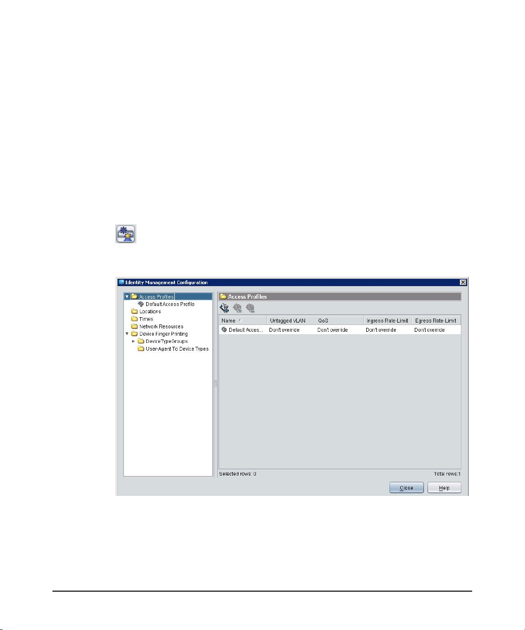
Understanding the IDM Configuration Model
10. For the devices that will perform MAC authentication, you can configure AutoAllow OUI to provide automatic authentication based on those devices’ MAC
address prefixes.
Using Identity Driven Manager
Configuring Identity Management
All of the elements described for configuring user access in IDM are available in the
Identity Management Configuration window.
To launch the Identity Management Configuration window:
1. Right-click the Identity Management Home navigation tree, and select Configure
Identity Management.
OR
2. Click the Configure Identity Management button in the Domains pane toolbar.
The Identity Management Configuration default display is the Access Profiles pane
with the Default Access Profile.
Figure 3-1. Identity Management Configuration, default display
Click the node in the navigation tree to display the defined configuration parameters
and add or edit new configuration parameters, as described in the following sections.
3-3
Page 68

Using Identity Driven Manager
Configuring Locations
Configuring Locations
Locations in IDM identify the switch and/or ports on the switch and wireless access
points where users connect to the network. Users generally are allowed to log in to
the network from a variety of locations, IDM allows you to create customized
locations to match specific environments.
For example, a generalized company "location" may include all of the ports on a
switch, or multiple switches through which users can connect to the network. You
can define a lobby location as a single switch, or a single port on the switch, in order
to restrict access to the network for visitors attaching to the network in the lobby.
To configure a location:
Select the Locations node from the Identity Management Configuration navigation
tree to display the Locations pane.
Figure 3-2. Locations pane
Note: IDM also lets you include wireless devices in the location configuration. Selecting
Enable Enhanced Wireless Support in IDM Preferences adds a wireless devices tab
to the Create a new Locations window.
3-4
Page 69

Using Identity Driven Manager
Configuring Locations
Adding a New Location
To create a new location:
1. Click the New Location button in the Locations toolbar to display the Create a
new Location window.
Figure 3-3. Create a New Location display
2. Type a Name for the location.
3. Type a Description for the location.
To add wired devices to the location:
4. Click Add device to open the New Device window, and define the devices and/
or port combinations that will be included in the location.
See “To add a wireless device to a Location” on page 3-7 for details on support for
wireless locations.
3-5
Page 70

Using Identity Driven Manager
Configuring Locations
Figure 3-4. New Device window
5. Use the Select Device Group list to select the Agent and device model that will
6. Enter the device to be added.
be allocated to users logging in from the associated location.
a. Using the Device Selection option:
i. Use the menu to select a device group. This will enable the Select
Device menu in the next field.
ii. Select a device from the list of available devices. The list is populated
with the IP address or DNS name for all (PCM managed) devices in
the selected group.
b. Using the Manually enter device address option:
i. Select the check box to enable the data entry field below it.
ii. Type the IP address or DNS name of the device to be added.
Note: If PMM is licensed, this dialog will not show wireless device. You must add wireless
devices from the Wireless Devices tab on the Create a new Location window. If
PMM is not licensed, wireless devices will appear in this dialog. However, you will
not be able to select any ports, the only option will be Any port.
3-6
Page 71

Using Identity Driven Manager
Configuring Locations
7. Use the Port Selection section to define the ports on the device that will be
associated with the location.
• Click to select Any port on the switch, or
• Click Select ports, then use the lists to select the Begin and End ports on
the device that will be associated with the new location.
If you manually entered the device address, the Begin port and End port
menus are disabled, and you must manually enter the ports.
8. Click OK to save the New Device settings to the Location, and close the window.
Notes: If a switch in the device list is not configured to authenticate with the RADIUS
server, the settings in IDM will have no affect.
You can type in an IP address for non-PCM devices and if the device uses industry
standard RADIUS protocols, the settings should work; however, HP does not
provide support for IDM configurations with non-PCM devices.
9. The Device address and ports information is displayed in the New Location
window.
10. Repeat steps 4 through 7 to add additional devices to the Location, or click OK
to save the new Location and close the window.
To add a wireless device to a Location:
1. On the Create a new Location window, click the Wireless devices tab.
3-7
Page 72

Using Identity Driven Manager
Configuring Locations
Figure 3-5. Create a New Location, Wireless Devices
2. Click Add Device to display the Wireless Devices Dialog.
All discovered Radios and radio ports are displayed.
3-8
Figure 3-6. Select Wireless Device for a location
Page 73

Using Identity Driven Manager
3. Click the check box(es) to select the radio ports to be included in the location,
and then click OK to save the selection and return to the Create a new Location
(Wireless Devices tab) window.
4. Click OK to save and exit, or repeat the steps to add additional devices to the
location.
Configuring Locations
Modifying a Location
To edit the information for an existing Location:
1. Select the Locations node from the Identity Management Configuration navigation tree to display the Locations pane with the list of defined locations.
2. Double-click a location from the navigation tree or from the Locations list to
open the (modify) location pane.
You can also select the location in the list, then click the Edit Location button in
the toolbar to display the Location in edit mode.
3. Edit the location Name and Description as needed.
4. Edit the device configuration for the location as needed:
• To Modify the device settings, select the device in the list, then click Edit
device to display the Modify Device window.
The Modify Device window contains the same fields as the New Device
window. You can edit the ports associated with the location, or you can
choose a different device and reset the ports for the new device. Click OK
to save your changes and close the window.
The changes are displayed in the Location pane.
• To add another device, click Add Device.
• To delete a device, select the device in the list, then click Delete Device.
5. Click OK to save the location changes and close the Locations window.
Click Cancel to close the window without saving the changes. The original
location configuration will be maintained.
Note: When modifying Locations, make sure all devices for the location are configured
with the appropriate VLANs. If you Modify a Location that is part of a VLAN
(subnet) and that Location is currently used in an Access Policy Group rule, IDM
will check to make sure that the VLAN exists. If not, an error message is displayed.
3-9
Page 74

Using Identity Driven Manager
Configuring Locations
Deleting a Location
To remove an existing Location:
1. Select the Locations node from the Identity Management Configuration navigation tree to display the Locations pane with the list of defined locations.
2. Click a location from the list to select it.
3. Click the Delete Location button in the toolbar to remove the location.
The first time you use the Delete Location option, a warning pop-up is displayed.
Click OK to continue, or Cancel to stop the delete process.
4. The location is removed from the Locations list.
Note: If you modify or delete a Location, check to make sure that the changes do not
adversely affect users in Access Policy Groups where the Location is used.
3-10
Page 75

Using Identity Driven Manager
Configuring Times
Configuring Times
Times are used to define the hours and days when a user can connect to the network.
When included in the Access Policy Group rules, the time can be used to allow or
deny access from specific locations at specific time. For example, students might be
allowed network access from the "Classroom" location during weekdays, from 9:00
am to 5:00 pm, but denied access from the Classroom at any other time.
To configure a Time:
1. On the IDM main window, select Tools > Configure Times.
OR
Select the Times node from the Identity Management Configuration navigation
tree to display the Times pane.
Figure 3-7. Identity Management Configuration, Times pane
The Times pane lists the name and description of defined times. Double-click the
time from the list, or select the time from the navigation tree to display the Time’s
properties, including:
Table 3-1. Times pane parameters
Field/Section Displays...
Name The name used to identify the time
Description A brief description of the time
Time The time of day when the access policy group is active.
3-11
Page 76
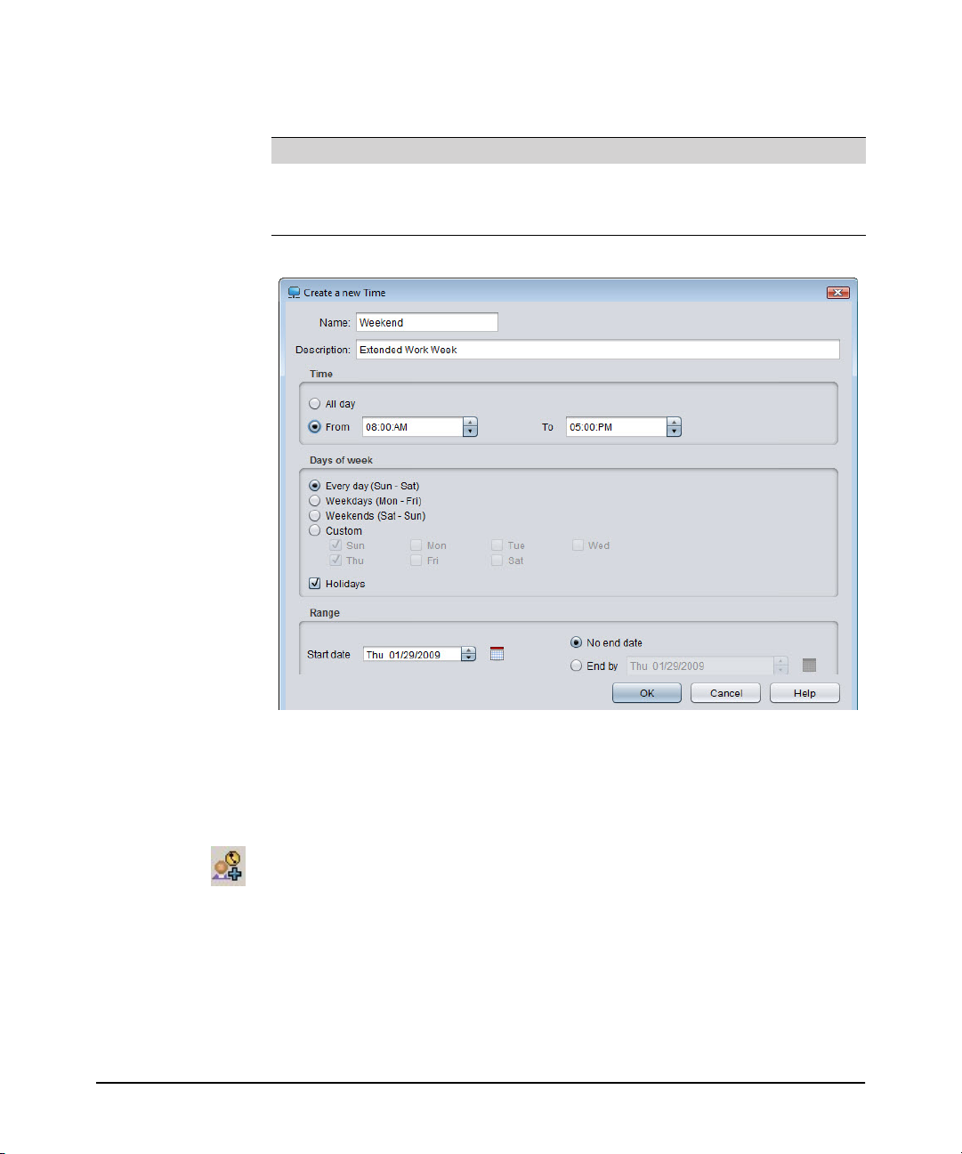
Using Identity Driven Manager
Configuring Times
Table 3-1. Times pane parameters (Continued)
Field/Section Displays...
Days of week The days of the week when the access policy group is active
Range The dates during which the time will be in effect. A start date must be
specified.
3-12
Figure 3-8. Times Properties
Creating a New Time
To create a new Time:
1. In the Times Pane, click the Add New Time button to display the Create a new
Time window.
Page 77

Using Identity Driven Manager
Configuring Times
Figure 3-9. Create a New Time
2. Define the properties for the new time.
Table 3-2. IDM Time parameters
Field/Section Entry
Name Type a name used to identify the time
Description Type a brief description of the time
Time Select a time of day when user will be accepted on the network. To allow
Days of week Select the days of the week that a user will be accepted or rejected on the
Range Select the dates during which the time will be in effect. Select the Start Date
access the entire day, select the All day radio button.
To restrict access to specific hours of the day, select the From radio button
and type the beginning and ending times. The ending time must be later than
the beginning time. AM or PM must be specified.
network. Select the radio button next to the desired days. Select the Custom
radio button to enable the day(s) of the week check boxes.
and then select the No End Date radio button, or select the End Date.
3. Click OK to save the new Time and close the pane. The new time appears in the
Times window.
3-13
Page 78

Using Identity Driven Manager
Configuring Times
Modifying a Time
To modify a Time:
1. In the Times pane, select a Time from the navigation tree to display the Time
details in edit mode, similar to the Create a new Time pane.
You can also select the Time from the list then click the Modify Time button in
the toolbar to display the modify pane.
2. Modify the time parameters, as described in Table 3-2 on page 3-13.
3. Click OK to save your changes and close the window.
Note: If you modify or delete a Time, check to make sure that the changes do not adversely
affect users in Access Policy Groups where the Time is used.
Deleting a Time
To remove an existing Time:
1. In the Times pane, click a Time from the list to select it.
2. Click the Delete Time button in the toolbar to remove the location.
The first time you use the Delete Time option, a warning pop-up is displayed.
Click OK to continue, or Cancel to stop the delete process.
3. The Time is removed from the Times list.
3-14
Defining Holidays
To add holidays for use when defining Times:
1. In the Times pane, click the Holidays button in the toolbar to launch the Holidays
window.
Figure 3-10. Holidays window
Page 79

Using Identity Driven Manager
2. Click Add to launch the Add Holiday window.
Figure 3-11. Add Holiday
3. The Date field defaults to the current date. You can use the field buttons to
increase or decrease the date. You can also type a new date.
4. In the Description field, enter the text that will identify the holiday in the
Holidays list.
5. Click OK to save the holiday and close the window. The new holiday appears in
the Holidays list.
To edit a Holiday, select it from the Holidays list, then click Edit. This launches the
Edit Holiday window, which is similar to the Add Holiday window.
To delete a Holiday, select it from the Holidays list, then click Delete. Click Yes in
the confirmation pop-up to complete the process.
Device Finger Printing
Device Finger Printing
Device Finger Printing Feature in IDM/SNAC helps to control user access to a
network, based on the device type they use to log-on to the network. IDM is enhanced
to allow configuration of ‘access rules’ to the network based on device types. IDM
Administrator is now able to create ‘Device Type Group’ objects that can hold one
or more device type and can associate Device type group object to an existing access
policy rule in IDM. They can also create new access policy rule and associate device
type group object to the new access policy rule.
Configuring Device Finger Printing
In the Identity Management Configuration window, a new node is added as Device
Finger Printing. There are two nodes added to Device Finger Printing, that is, Device
type groups and User-Agent to Device Types.
3-15
Page 80

Using Identity Driven Manager
Device Finger Printing
Figure 3-12. Device Finger Printing
3-16
User Agent To Device Types Mapping
The administrator can see the list of configured (both pre-loaded and user defined)
User-Agent Pattern to Device Type mappings from this node. It has three columns
with some default values.
• Position
• Pattern in User-Agent
Page 81
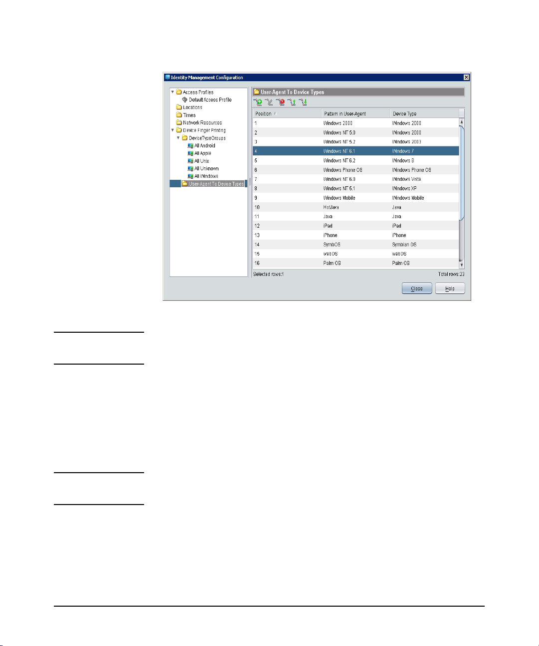
• Device Type
Figure 3-13. User Agent to Device Types
Using Identity Driven Manager
Device Finger Printing
Note: Users tab view reflects the device type corresponding to the user agent pattern
which is listed with the lowest position number in the above list.
Creating a New User Agent Mapping
To create a New User Agent Mapping
1. Enter the user agent pattern to match for in the user agent string, and the Device
type (you can also enter new or select from existing types). The newly inserted
pattern is inserted at the first position.
Note: For the user agent pattern mapping to take effect, it has to be a part of one or more
Device Type Group objects.
2. The Administrator can change the insertion of new pattern by choosing the
pattern before which to insert the new pattern. Additionally, the administrator
can also add the new pattern to any existing device type groups.
3-17
Page 82

Using Identity Driven Manager
Device Finger Printing
Figure 3-14. New User Agent to Device Type Mapping
3-18
Bulk Import of User Agent Pattern Mappings
To do bulk import of user-agent patterns:
1. Stop the PCM Service.
2. Update the server/config/UserAgentPattern file with the required patterns.
3. Edit server/config/globalprops.prp.
4. Remove the ‘IDMDeviceFingerPrinting’ section.
5. Start the PCM Server service.
The new patterns in the file now appears under the 'User-Agent To Device Type' node
in the 'Configure Identity Management'.
Since only 'bulk import' is supported and not 'bulk update', deletion of existing UserAgent Patterns can be done only through the IDM GUI.
Deleting a User Agent Mapping
To delete a User Agent Mapping
1. Select the user agent pattern mappings from the list, and delete.
Page 83

Using Identity Driven Manager
2. A dialog box appears to confirm before deleting the entry. If the device type
being deleted is in use in some Device Group, deletion is not allowed.
Further, if pattern that is selected for deletion is one of the catch-all patterns defined
in the Creating a Global Rule, then the deletion will fail again with appropriate notice.
Device Finger Printing
Moving up User Agent Mapping
The Administrator can move a selected pattern Up in the table. However, only one
pattern at a time can be moved up. A selected pattern can be moved up only till the
first position.
Moving down User Agent Mapping
The Administrator can move a selected pattern down in the table. However, only one
pattern at a time can be moved down. A selected pattern can be moved down only
till the last position.
Device Type Groups
Device Type Groups node is selected in Identity Management Configuration window,
a table of the configured Device Type Group objects is displayed on the right side of
the screen.The table has the following two columns:
• Device Type Group Name
• Device Type Group Description.
3-19
Page 84

Using Identity Driven Manager
Device Finger Printing
Under Device Type Groups node, each node represents one Device Type Group
object. A Device Type Group object can hold either specific Device Types or a mix
of various kinds of devices. The Device Type Group Name holds the unique value.
3-20
Figure 3-15. Device Type Groups
Page 85

Using Identity Driven Manager
To edit the selected Device type group object, click any entry in Device Type Group
Name.
Device Finger Printing
Figure 3-16. Edit Device Type Group
Creating a New Device Type Group Object
To create a New Device Type Group Object:
1. Enter the Device Type Group Name, Description, and then select elements from
the list of Device Types.
3-21
Page 86

Using Identity Driven Manager
Device Finger Printing
Figure 3-17. Create a new Device Type Group
2. Click Add/Remove. A dialog box appears to select device types.
3-22
Page 87

Using Identity Driven Manager
Device Finger Printing
Figure 3-18. Select Device Types
3. After selecting the device types, Click Ok.
4. The new group is added to the list of existing device groups in the navigation tree.
5. Click Close to save the device type group to the database.
3-23
Page 88

Using Identity Driven Manager
Device Finger Printing
Figure 3-19. Edit/Delete Created Groups
Modify Device Type Group
To modify a new Device Type Group:
1. From the Identity Management Configuration navigation tree, select Device
Finger Printing and then select Device Type Groups.
2. Edit the device type group using one of the following ways :
a. Select the device type group node from the navigation tree.
b. Select the device type group from the table and click Edit or Double click
on the device type row in the table.
3. Navigate to the Edit screen, to modify the description of the group, and then edit
the list of device types present in the group.
4. To Add/Remove device types, Click on Add/Remove. A Select Device type
dialog box appears to do the required modifications.
5. Click Close to save the modifications to the device type group.
3-24
Page 89

Using Identity Driven Manager
Configuring Network Resources
IDM has pre-configured Device Type Groups for each of all the catch all patterns.
• All Android (For all Android devices)
• All Windows (For all Windows devices)
• All Unix (For all Unix devices)
• All Apple (For all Apple devices)
• All Unknown (For all Unknown devices)
The advantage of these pre-configured Device Type Group is that when registering
users, if user-agent string matches one of the catch-all regex patterns, user's device
type automatically becomes a member of the respective Device Type Group. As a
result, the user's access to the network is immediately controlled based on the device
type, without any additional effort from the Administrator. The Global Rules or
Access Rules must be configured to complete the Device Finger Printing configuration.
Configuring Network Resources
Network Resources in IDM are used to permit or deny traffic to and from specified
sources and destination. This is done by configuring an IP-based filter based on either:
■ The IPv4 or IPv6 address (individual address or subnet address) of the
source or destination, or
■ The protocol (IP, ICMP, VRRP, and so forth)
■ The TCP or UDP port (that is, based on protocol and application, such as
Telnet or HTTP)
For example, you can create a Network Resource to restrict “guest accounts” so that
they only have access to the external Internet, and no access to internal resources. Or
you can define a resource that allows HR employees to access the payroll systems,
and denies access to all other employees.
Note: Network Resource features can be used only for switches that support IDM-based
ACLs. See “Device Support for IDM Features” on page A-1.
To configure a Network Resource:
1. Select the Network Resources node from the Identity Management Configuration navigation tree to display the Network Resources pane.
3-25
Page 90

Using Identity Driven Manager
Configuring Network Resources
Figure 3-20. Network Resources
The Network Resources window lists the name and parameters for defined resources,
including:
Table 3-3. Network Resources parameters
3-26
Column Displays...
Name The name used to identify the resource
IP Address The IP Address for the switch associated with the resource ("any" if the
resource is being filtered by protocol).
Network Mask The subnet mask for the IP Address.
Ports The device port(s) associated with the resource or Any if the resource is
being filtered by protocol.
Ports can be selected by number, or friendly port name. Refer to the section
on "Using Friendly (Optional) Port Names" in the Management and
Configuration Guide for your switch for details.
Protocol The protocol (UDP, TCP, or IP) used to filter access to the resource.
Double-click the Network Resource from the list, or select it from the navigation
tree, to display individual Network Resource configuration details.
Page 91

Using Identity Driven Manager
Configuring Network Resources
Figure 3-21. Network Resources - Details
Note When you open the details window, it is in “Edit” mode. You can modify the entries
in the display fields, and the changes are automatically saved when you click Close.
For details on the field entries, refer to the definitions under “Adding a Network
Resource” on the next page.
Adding a Network Resource
To define a new Network Resource:
1. In the Network Resources pane, click the Add Network Resource button to
display the Define Network Resource window.
3-27
Page 92
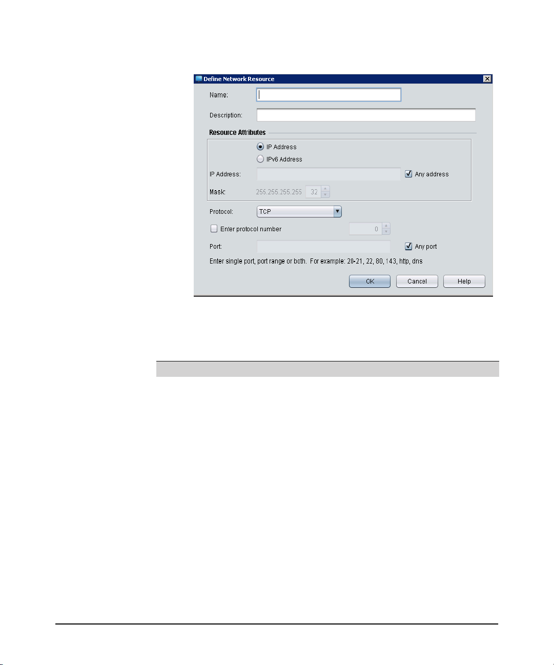
Using Identity Driven Manager
Configuring Network Resources
Figure 3-22. Define Network Resource
2. Define the properties for the network resource.
Table 3-4. IDM Network Resource parameters
Field/Section Entry
Name The name used to identify the network resource
Description A brief description of the network resource (optional)
Resource Attributes:
IP Address/IPv6
Address
Protocol Select UDP, TCP, or IP to identify the protocol used to filter access to the
To filter by device address, clear the Any Address check box, select the
address type as either IP Address or IPv6 Address, and type the IP address
for the switch associated with the resource in the IP Address field.
Use the Any address option if you will be filtering by Protocol and
application port only, and not by specific device or port.
Mask The subnet mask for the IP Address (if used). Use the up/down buttons [
▼] to set the mask number.
resource. Protocol can be used alone or with an IP address and port
parameters to define the network resource access.
To use a custom protocol number for a network resource, check the Enter
protocol number check box and type the protocol number (0-137)
▲,
3-28
Page 93

Using Identity Driven Manager
Configuring Network Resources
Table 3-4. IDM Network Resource parameters (Continued)
Field/Section Entry
Port Any port is selected by default, which means all ports associated to the IP
address are included in the network resource definition. To specify a port
for the network resource, check the Any port check box to clear it and
enable the Port field. Enter the port number, or friendly port name* used for
the resource.
* Valid port names supported in IDM include: ftp, syslog, ldap, http, imap4,
imap3, nntp, pop2, pop3, smtp, ssl, telnet, bootpc, bootps, ssh, dhcp, ntp,
radius, rip, snmpsnmp-trap, tftp.
Note: If you are setting a resource to represent an application port such as dhcp or smtp
or http, you must make sure that you set the correct protocol, either TCP or UDP.
If you do not set the correct protocol, the rule will not operate as intended at the
switch or access point.
3. Click OK to save the Network Resource definition and close the window.
All entries are saved immediately upon entry. This allows you to configure several
IDM features without closing and reopening the Configure Identity Management
window.
Click Cancel to close the window without saving your changes.
Modifying a Network Resource
To modify a Network Resource:
1. In the Network Resources pane, select the network resource to edit from the list,
then click the Edit Network Resource button to display the Define Network
Resource window.
2. Edit the properties as needed. Refer to “Adding a Network Resource” on the
previous page for definitions.
3. Click OK to save the Network Resource definition and close the window.
Deleting a Network Resource
To delete a Network Resource:
1. In the Network Resources pane, select the network resource to edit from the list,
then click the Edit Network Resource button to display the Define Network
Resource window.
3-29
Page 94

Using Identity Driven Manager
Configuring Network Resources
I 2. Click in the list to select the network resource to delete, then click the Delete
3. Click Yes in the confirmation pop-up to complete the process.
The selected network resource is removed from the Network Resources list display.
Network Resource button.
3-30
Page 95

Using Identity Driven Manager
Configuring Access Profiles
Configuring Access Profiles
IDM uses an Access Profile to set the VLAN, QoS, Bandwidth (rate-limits) and
Network Resource access rules that are applied to the user when they are authenticated on the network. This is where the real benefits of "access control" are realized.
When users log in, the Access Profile dynamically configures the switch or wireless
access point settings to provide the proper network access and resources for the user.
To begin, select the Access Profiles node from the Identity Management Configuration navigation tree to display the Access Profiles window.
Figure 3-23. Access Profiles window
The Access Profiles window lists defined Access Profiles, including:
Table 3-5. Access Profiles parameters
Column Displays...
Name The name used to identify the profile
Untagged VLAN The bame of the untagged VLAN to which users in the group are
QoS The Quality of Service setting
Ingress Rate Limit The maximum amount of traffic (in Kbps) allowed from this user
Egress Rate Limit The maximum amount of traffic (in Kbps) allowed to this user
assigned when they log in
The Access Profile tells the switch to override any local settings for the port the user
is accessing with the settings specified in IDM.
3-31
Page 96

Using Identity Driven Manager
Configuring Access Profiles
Select the Access Profile node from the navigation tree, or double-click a profile from
the list to display the details of the selected profile.The Name, Description, and
Access Attributes are the same as defined in the Access Profiles list. The Network
Resources section lists the Network Resources included in the profile:
Table 3-6. Access Profile - Network Resources parameters
Column Displays...
Priority The order in which the network resource rules are evaluated; the first one to
Action If access to the Network Resource is allowed or denied.
Resource The defined network resource name.
Accounting Whether or not the switch will count the number of hits using this rule.
Creating a New Access Profile
To create a new Access Profile:
1. On the Access Profiles window, click the Add Access Profile button in the
match each incoming packet is applied
toolbar to display the Create a new Access Profile window.
3-32
Figure 3-24. Create Access Profile
Page 97

Using Identity Driven Manager
Configuring Access Profiles
2. Define the attributes for the Access Profile:
Table 3-7. New Access Profile parameters
Field/Section Entry
Name Type a name used to identify the Access Profile
Description Type a brief description of the Access Profile
Untagged VLAN or
Tagged VLANs
QoS Select the Quality of Service, or “priority” given to outbound traffic under
Ingress rate-limit
Egress rate-limit
Select the type of VLAN used for the access profile.
To select an untagged VLAN, check the Untagged VLAN check box and
select the VLAN that can be accessed from the list. Selecting a VLAN
from the list grants the user access to that network segment only.
To select a tagged VLAN, check the Tagged VLAN check box and click
Edit. When the VLAN Selection window appears, select the tagged
VLANs to be accessed from the Available VLANs list and click >> to select
them. When all tagged VLANS that can be accessed are displayed in the
Selected VLANs list, click OK to close the window and return to the
Identity Management Configuration window.
Keep the following in mind when selecting VLANs:
• The list of VLANs is derived from the VLANs that PCM discovers.
Therefore, you should run Discovery to populate the VLAN list before
creating a new Access Profile.
• Untagged VLANs and tagged VLANs are mutually exclusive, meaning
the customer cannot select the same VLAN for untagged and tagged.
• The VLAN set for a user overrides the statically configured VLAN, as
well as the auth-vid that may have been configured for that port.
• If an unauth-vid is set and the user is rejected by IDM for any reason,
the port is opened and the VLAN is set to the unauth-vid.
this profile. Select the setting from the pull-down menu.
Select the rate-limits applied for this profile. Use the up-down arrows to
increase or decrease the bandwidth setting. The default setting is 1000
Kbps (1 Mbps) AP1
Note: This is translated to a percentage of bandwidth at the switch.
Notes: If you are assigning any VLAN other than the default VLAN, ensure that the VLAN
is configured correctly on the all switches to which this access profile will be applied
before defining the access profile.
The VLAN that gets set for a user will override the statically configured VLAN, as
well as the auth-vid which may have been configured for that port. Note also that if
an unauth-vid is set and the user is rejected by IDM for any reason, the port is opened
and the VLAN is set to the unauth-vid.
3-33
Page 98

Using Identity Driven Manager
Configuring Access Profiles
3. If you want the IDM QoS attributes to override the switch attributes, use the QoS
4. In the Ingress rate-limit field, select the maximum bandwidth or rate limit
5. In the Egress rate-limit field, select the maximum bandwidth or rate limit
6. To assign the Network Resources, click Edit. This launches the Network
list to select the quality of service or priority for outbound traffic of users in
groups associated with the access profile. QoS ranges from lowest to highest,
with Normal being the default.
allocated for traffic from users assigned to the Access Policy Group using the
Access Profile. The default setting is 1000 Kbps (1 Mbps), which is translated
to a percentage of bandwidth at the switch.
allocated for traffic to users assigned to the Access Policy Group using the
Access Profile. The default setting is 1000 Kbps (1 Mbps), which is translated
to a percentage of bandwidth at the switch.
Resource Assignment Wizard.
3-34
Figure 3-25. Network Resource Assignment Wizard
7. Click Next to continue to the Allowed Network Resources window.
Page 99

Using Identity Driven Manager
Configuring Access Profiles
Figure 3-26. Network Resource Assignment Wizard, Allowed Network Resources
8. To permit access to Network Resources:
a. Select the Resource from the Available Resources list. Use shift-click to
select multiple resources.
b. Move the Available Resource(s) to the Allowed Resources list
(click >>).
c. Click Next to continue to the Denied Network Resources window.
3-35
Page 100
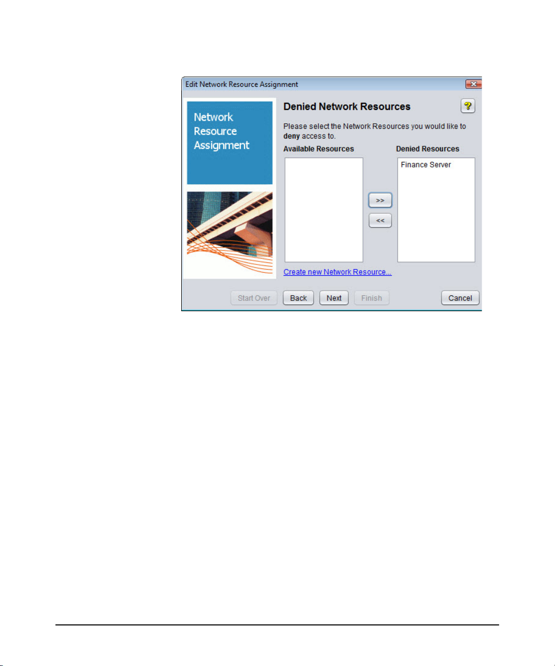
Using Identity Driven Manager
Configuring Access Profiles
Figure 3-27. Network Resource Assignment Wizard, Denied Network Resources
9. To deny access to Network Resources:
a. Select the Resource from the Available Resources list. Use shift-click to
select multiple resources.
b. Move the Available Resource(s) to the Denied Resources list
(click >>)
c. Click Next to continue to the Priority Assignment window.
3-36
 Loading...