

Page 1

HP HSR6800 Routers
Installation Guide
5998-4040
Part number: 5998-4040
Document version: 6PW102-20140210
Page 2

Legal and notice information
© Copyright 2014 Hewlett-Packard Development Company, L.P.
No part of this documentation may be reproduced or transmitted in any form or by any means without
prior written consent of Hewlett-Packard Development Company, L.P.
The information contained herein is subject to change without notice.
HEWLETT-PACKARD COMPANY MAKES NO WARRANTY OF ANY KIND WITH REGARD TO THIS
MATERIAL, INCLUDING, BUT NOT LIMITED TO, THE IMPLIED WARRANTIES OF MERCHANTABILITY
AND FITNESS FOR A PARTICULAR PURPOSE. Hewlett-Packard shall not be liable for errors contained
herein or for incidental or consequential damages in connection with the furnishing, performance, or
use of this material.
The only warranties for HP products and services are set forth in the express warranty statements
accompanying such products and services. Nothing herein should be construed as constituting an
additional warranty. HP shall not be liable for technical or editorial errors or omissions contained
herein.
Page 3

Contents
Preparing for installation ············································································································································· 1
Safety recommendations ·················································································································································· 1
Safety symbols ·························································································································································· 1
Electricity safety ························································································································································ 2
Laser safety ································································································································································ 2
Router moving ··························································································································································· 2
ESD prevention ························································································································································· 3
Examining the installation site ········································································································································· 4
Weight support ························································································································································· 4
Temperature ······························································································································································ 4
Humidity ···································································································································································· 5
Altitude ······································································································································································ 5
Cleanness ·································································································································································· 5
Cooling system ························································································································································· 6
EMI ············································································································································································· 7
Lightning protection ·················································································································································· 8
Space ········································································································································································· 8
Power supply ····························································································································································· 8
Installation accessories ····················································································································································· 8
Installing the router ····················································································································································· 10
Installation flow ······························································································································································ 10
Installing a cable management bracket ······················································································································· 10
Installing the router in a 19-inch rack ·························································································································· 11
Installing cage nuts to the rack ···························································································································· 11
Installing the mounting brackets to the router ····································································································· 12
Installing the router in a 19-inch rack ················································································································· 13
Grounding the router ····················································································································································· 13
Installing a power module ············································································································································· 14
Installing an MPU and a switching fabric module ······································································································ 15
Installing an RSE-X2 MPU ····································································································································· 15
Installing an SFE-X1 switching fabric module ····································································································· 15
Installing an LPU ····························································································································································· 16
Installing a HIM/MIM ···················································································································································· 17
Installing a CF card ························································································································································ 18
Installing optional components ····································································································································· 18
Installing an air filter ············································································································································· 18
Connecting the power cord ·········································································································································· 20
Connecting an AC power cord ··························································································································· 20
Connecting DC power cords ······························································································································· 21
Connecting interface cables ······································································································································ 25
Connecting the AUX cable ············································································································································ 25
Overview ································································································································································ 25
Connecting the AUX cable ··································································································································· 25
Connecting an Ethernet cable······································································································································· 26
Overview ································································································································································ 26
Making an Ethernet cable ···································································································································· 27
Connecting an Ethernet cable ······························································································································ 28
Connecting a fiber cable ·············································································································································· 28
i
Page 4

Transceiver module overview ······························································································································· 28
Fiber cable overview ············································································································································· 29
Connecting a fiber cable ······································································································································ 30
Connecting an E1/T1 cable ········································································································································· 31
Overview ································································································································································ 31
Connecting an E1/T1 cable ································································································································ 32
Connecting a CE3/CT3 cable ····································································································································· 34
Overview ································································································································································ 34
Connecting a CE3/CT3 cable ····························································································································· 34
Connecting a serial port cable ····································································································································· 35
Overview ································································································································································ 35
Connecting a serial port cable ···························································································································· 37
Accessing the router ··················································································································································· 39
Login methods ································································································································································· 39
Logging in through the console port ···························································································································· 39
Setting up a configuration environment ·············································································································· 39
Setting terminal parameters ·································································································································· 40
Powering on the router ·················································································································································· 43
Verifying before power-on ···································································································································· 43
Powering on the router ········································································································································· 43
Displaying boot information ································································································································· 43
Logging in to the router through Telnet/SSH ·············································································································· 44
Logging in to the router through the AUX port ············································································································ 44
Configuring basic settings ············································································································································· 45
Replacement procedures ··········································································································································· 46
Safety recommendations ··············································································································································· 46
Replacing a power module ··········································································································································· 46
Replacing an MPU and a switching fabric module ···································································································· 47
Prerequisites ··························································································································································· 47
Replacing an RSE-X2 MPU ··································································································································· 47
Replacing an SFE-X1 ············································································································································· 47
Replacing an LPU ··························································································································································· 48
Replacing a HIM/MIM ·················································································································································· 49
Replacing a CF card ······················································································································································ 50
Replacing a transceiver module ··································································································································· 50
Replacing a fan tray ······················································································································································ 51
Replacing a fan tray for an HSR6802/HSR6804 router ·················································································· 51
Replacing a fan tray for an HSR6808 router ····································································································· 51
Replacing an air filter ···················································································································································· 52
Replacing an air filter for an HSR6802/HSR6804 router ··············································································· 52
Replacing an air filter for an HSR6808 router ··································································································· 53
Replacing a memory module ········································································································································ 53
Memory module structure ····································································································································· 54
Replacing a memory module ······························································································································· 54
Hardware management and maintenance ·············································································································· 56
Displaying the hardware information of the router ···································································································· 56
Displaying the version information of the router ································································································ 56
Displaying the running statistics for the router ··································································································· 57
Displaying detailed information about a card ··································································································· 57
Displaying the electrical label data ····················································································································· 58
Displaying the CPU usage statistics ····················································································································· 59
Displaying the MPU memory usage ···················································································································· 59
Displaying the CF card information ···················································································································· 60
ii
Page 5

Displaying the fan operating status ····················································································································· 60
Displaying the power module operating status ·································································································· 61
Displaying the alarming thresholds of a card ············································································································· 61
Port configuration and management ···························································································································· 62
Configuring a combo interface ···························································································································· 62
Displaying and verifying transceiver modules ··································································································· 63
Active and standby switchover for MPUs ···················································································································· 64
Troubleshooting system exceptions ······························································································································ 64
Configuring the exception handling methods ···································································································· 64
Displaying the exception handling method ········································································································ 65
Rebooting a card or router ··········································································································································· 65
Troubleshooting ·························································································································································· 67
MPU failures ··································································································································································· 67
RUN LED is off ······················································································································································· 67
RUN LED fast flashes ············································································································································· 67
ALM LED is steady on or flashes ·························································································································· 67
PALM LED is steady on ········································································································································· 68
LPU failures ····································································································································································· 68
RUN LED is off ······················································································································································· 68
RUN LED fast flashes ············································································································································· 69
Power module failures ··················································································································································· 69
Power LED is off ····················································································································································· 69
Red power LED is on ············································································································································· 70
Fan failures ····································································································································································· 70
Fan tray is absent ·················································································································································· 70
ALM LED is red ······················································································································································ 70
HIM/MIM failures ·························································································································································· 71
Configuration system problems ···································································································································· 71
No terminal display ·············································································································································· 71
Garbled terminal display ······································································································································ 71
No response from the serial port ························································································································· 72
Dealing with password loss ·········································································································································· 72
Examining the state of password recovery capability ······················································································· 73
Dealing with console login password loss when password recovery capability is enabled ························ 74
Dealing with user privilege level password loss when password recovery capability is enabled ··············· 75
Dealing with password loss when password recovery capability is disabled ··············································· 76
Cooling system failure ··················································································································································· 77
Ethernet port failure ························································································································································ 77
HIM/MIM, cable, and connection failure ··················································································································· 78
Software upgrade failures ············································································································································· 78
No response from the serial port of the MPU ····································································································· 78
TFTP upgrade failure ············································································································································· 78
FTP upgrade failure ··············································································································································· 79
System software image file missing errors ·················································································································· 79
Appendix A Chassis views and technical specifications ························································································ 80
Chassis views ································································································································································· 80
HSR6802 ······························································································································································· 80
HSR6804 ······························································································································································· 81
HSR6808 ······························································································································································· 83
Dimensions and weight ················································································································································· 84
Power consumption ························································································································································ 85
Power module ································································································································································· 86
AC power module ················································································································································· 86
iii
Page 6

DC power module ················································································································································· 87
Fan tray specifications ··················································································································································· 89
MPU ················································································································································································· 90
RSE-X2 ···································································································································································· 90
Components ··························································································································································· 92
SFE-X1 ····································································································································································· 94
LPU ··················································································································································································· 95
FIP-110 ··································································································································································· 95
FIP-210 ··································································································································································· 97
FIP-300 ··································································································································································· 98
FIP-310 ································································································································································· 100
FIP-600 ································································································································································· 102
SAP-48GBE ·························································································································································· 103
SAP-24GBP ·························································································································································· 104
SAP-48GBP ·························································································································································· 106
SAP-4EXP ······························································································································································ 107
SPE/OAP ······································································································································································ 108
HIM/MIM ······································································································································································ 108
Appendix B LEDs ····················································································································································· 109
MPU and switching fabric module LEDs ···················································································································· 109
LPU LEDs ········································································································································································ 111
FIP LEDs································································································································································· 111
SAP LEDs ······························································································································································ 114
SPE LEDs ········································································································································································ 117
HIM/MIM LEDs ···························································································································································· 117
Power module LEDs ······················································································································································ 117
Fan LEDs ········································································································································································ 118
Appendix C Arranging slots and numbering interfaces ······················································································· 121
Slot arrangement ·························································································································································· 121
Available slots for cards ·············································································································································· 122
Numbering interfaces ·················································································································································· 123
Examples ······································································································································································· 123
Example 1 ···························································································································································· 123
Example 2 ···························································································································································· 123
Appendix D Cable management ··························································································································· 125
General cabling requirements ···································································································································· 125
Minimum curvature radius of cables ················································································································· 125
Minimum curvature radius of fibers ··················································································································· 125
Labeling cables····························································································································································· 125
Cable management guidelines ··································································································································· 126
Cable routing example ················································································································································ 128
Support and other resources ·································································································································· 129
Contacting HP ······························································································································································ 129
Subscription service ············································································································································ 129
Related information ······················································································································································ 129
Documents ···························································································································································· 129
Websites ······························································································································································· 129
Conventions ·································································································································································· 130
Index ········································································································································································ 132
iv
Page 7

Preparing for installation
The HP HSR6800 routers include the following models: HSR6802, HSR6804, and HSR6808.
Table 1 Models for the HP HSR6800 Routers
Product code Full name RMN
JG361A HP HSR6802 Router chassis BJNGA-BB0002 HSR6802
JG362A HP HSR6804 Router chassis BJNGA-BB0003 HSR6804
JG363A HP HSR6808 Router chassis BJNGA-BB0004 HSR6808
JG364A RT-RSE-X2 RSE-X2 RSE-X2
JG779A RT-RSE-X2-TAA RSE-X2 RSE-X2-TAA
JC166B RT-FIP-110-H3 FIP-110 FIP-110
JC167B RT-FIP-210-H3 FIP-210 FIP-210
JG671A RT-FIP-300 FIP-300 FIP-300
JG672A RT-FIP-310 FIP-310 FIP-310
JG360A RT-FIP-600 FIP-600 FIP-600
JC567A RT-SAP-48GBE-H3 SAP-48GBE SAP-48GBE
JC568A RT-SAP-24GBP-H3 SAP-24GBP SAP-24GBP
JG556A RT-SAP-48GBP SAP-48GBP SAP-48GBP
JG366A RT-SAP-4EXP SAP-4EXP SAP-4EXP
IMPORTANT:
For regulatory identification purposes, every HSR6800 Router is assigned a regulatory model
number(RMN). These regulatory numbers should not be confused with the marketing name HP HSR6800,
or product codes.
Abbreviation
Safety recommendations
Safety symbols
When reading this document, note the following symbols:
WARNIN G means an alert that calls attention to important information that if not understood or
followed can result in personal injury.
CAUTION means an alert that calls attention to important information that if not understood or
followed can result in data loss, data corruption, or damage to hardware or software.
1
Page 8

Electricity safety
W
g
g
W
• Locate the emergency power-off switch in the room before installation. Shut the power off at once in
case accident occurs. Disconnect the power cord of the router if necessary.
• Use an uninterrupted power supply (UPS).
• Do not work alone when the router has power. Do not touch any power plug when it is connected.
• Always make sure the power has been disconnected during the installation and replacement.
Laser safety
ARNING!
• Do not stare into any fiber port when the router has power. The laser li
might hurt your eyes.
ht emitted from the optical fiber
• Use fiber test equipment, rather than a microscope or magnifier to observe an operatin
or port when you test link connectivity or system parameters.
The routers are Class 1 laser devices.
When you connect an optical fiber, follow these guidelines:
• Some interface modules on the router provide shielded covers for the fiber ports (such as SFP ports).
Before using such fiber ports, remove the shielded covers. Keep the shielded covers secure. When
the fiber ports are not in use, install the shielded covers.
• Fiber connectors are fitted with dust caps. Keep the dust caps secure when the fiber connectors are
in use. Install dust caps when the fiber connectors are not in use to avoid damage to their end face.
Replace the dust cap if it is loose or polluted.
• Before connecting an optical fiber, use dust free paper and absolute alcohol to clean the end face
of the two fiber connectors. You can brush the end faces only in one direction.
• After a fiber is installed well, the bend radius must be not less than 10 cm (3.94 in).
• If the fiber has to pass through a metallic board hole, the hole must have a sleek and fully filleted
surface. (The filleting radius must be not less than 2 mm, or 0.08 in.) When passing through a
metallic board hole or bending along the acute side of mechanical parts, the fiber must wear
jackets or cushions.
Router moving
fiber connector
ARNING!
Do not hold the handle of the fan tray or power supply, the handle of the rear cover of the chassis, or the
air vents of chassis. Any attempt to carry the router with these parts might cause equipment damage or
even bodily injury.
When you move a router, follow these guidelines:
• Lift and put down the chassis slowly and never move suddenly.
• When you move a heavy router or multiple routers, use a pallet jack.
• Before moving the chassis, turn off the power switch and remove all cables, USB devices, and
mounting brackets.
2
Page 9

• If the router needs to be moved over a long distance, remove all field replacement units (FRUs), such
as HIMs/MIMs, put them separately in anti-static bags, and install the filler panels supplied with
router.
• If the router needs to be moved over a short distance, make sure all FRUs are securely seated in slots
and the screws are fastened.
• Make sure the accessories of the router are not lost or damaged during router moving.
• Make sure the ground is dry and flat and anti-slip measures are in place.
• Keep the chassis and installation tools away from walk areas.
ESD prevention
To prevent electrostatic discharge (ESD), follow these guidelines:
• Make sure the router and the rack are well grounded.
• An anti-static floor is installed and well grounded.
• Take dust-proof measures for the equipment room.
• Maintain the humidity and temperature in the acceptable range.
• Always wear an ESD wrist strap and ESD cloth when touching a circuit board or transceiver module.
• Place the removed CF card or LPU on an antistatic workbench, with the face upward, or put it into
an antistatic bag.
• Touch only the edges, instead of electronic components when you observe or move a removed CF
card or LPU.
To attach an ESD wrist strap:
1. Wear the wrist strap on your wrist.
2. Lock the wrist strap tight around your wrist to keep good contact with the skin.
3. Insert the ESD plug into the ESD socket.
4. Make sure the rack is well grounded.
3
Page 10
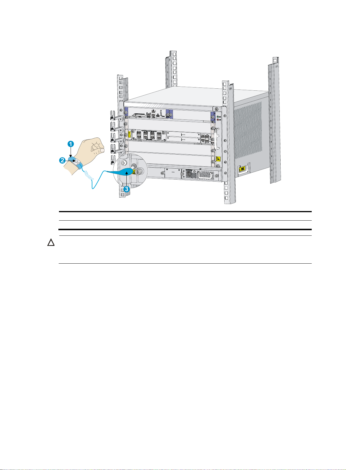
Figure 1 Attaching an ESD wrist strap
g
(1) ESD wrist strap (2) Lock
(3) ESD plug
CAUTION:
Check the resistance of the ESD wrist strap for safety. The resistance readin
to 10 megohm (Mohm) between human body and the ground.
Examining the installation site
The routers can only be used indoors. To make sure the router operates correctly and to prolong its
service lifetime, the installation site must meet the following requirements:
Weight support
Make sure the floor can support the total weight of the router and accessories (such as the rack and
HIMs/MIMs). For the weight of the router and accessories, see "Appendix A Chassis views and technical
spec
ifications."
Temperature
should be in the range of 1
To ensure normal operation of the router, make sure the room temperature meets the requirements
in Table 2.
4
Page 11

Table 2 Temperature requirements
p
y
p
Item Tem
Operating temperature 0°C to 45°C (32°F to 113°F)
Storage temperature –40°C to +70°C (–40°F to +158°F)
Humidity
Maintain appropriate humidity in your equipment room, as described in Table 3.
• Lasting high relative humidity tends to cause poor insulation, electricity creepage, mechanical
property change of materials, and corrosion of metal parts.
• Lasting low relative humidity is likely to result in loose screws due to washer contraction, and even
ESD, which causes the circuits to fail.
Table 3 Humidity requirements
Item Humidit
Operating humidity (noncondensing) 10% to 95%
Storage humidity (noncondensing) 5% to 95%
Altitude
erature
Table 4 Altitude requirements
Item Altitude
Operating altitude –60 m (–196.85 ft) to 4 km (2.49 miles)
Storage altitude –60 m (–196.85 ft) to 4.5 km (2.80 miles)
Cleanness
Dust buildup on the chassis might result in electrostatic adsorption, which causes poor contact of metal
components and contact points, especially when indoor relative humidity is low. In the worst case,
electrostatic adsorption can cause communication failure.
Table 5 Dust concentration limit in the equipment room
Substance Concentration limit (
Dust particles
NOTE:
Dust particle diameter ≥ 5 μm
articles/m3)
3 x 10⁴
(No visible dust on desk in three days)
The equipment room must also meet strict limits on salts, acids, and sulfides to eliminate corrosion and
premature aging of components, as shown in Table 6.
5
Page 12
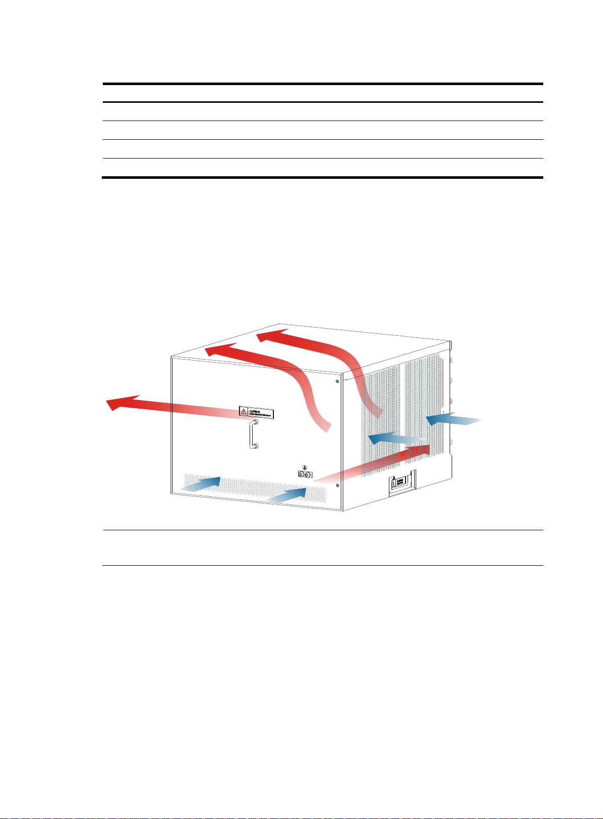
Table 6 Harmful gas limits in an equipment room
g
A
Gas Max. (m
SO2 0.2
H2S 0.006
NH
3
Cl
2
Cooling system
Fan trays of the routers are hot swappable and support automatic fan speed adjustment. To ensure good
ventilation, the following requirements must be met:
• Leave at least 10 cm (3.94 in) of clearance at the inlet and outlet air vents.
• The installation site has a good cooling system.
Figure 2 Airflow through the HSR6804 chassis
/m3)
0.05
0.01
NOTE:
n HSR6802 router uses the same airflow system as an HSR6804 router.
6
Page 13
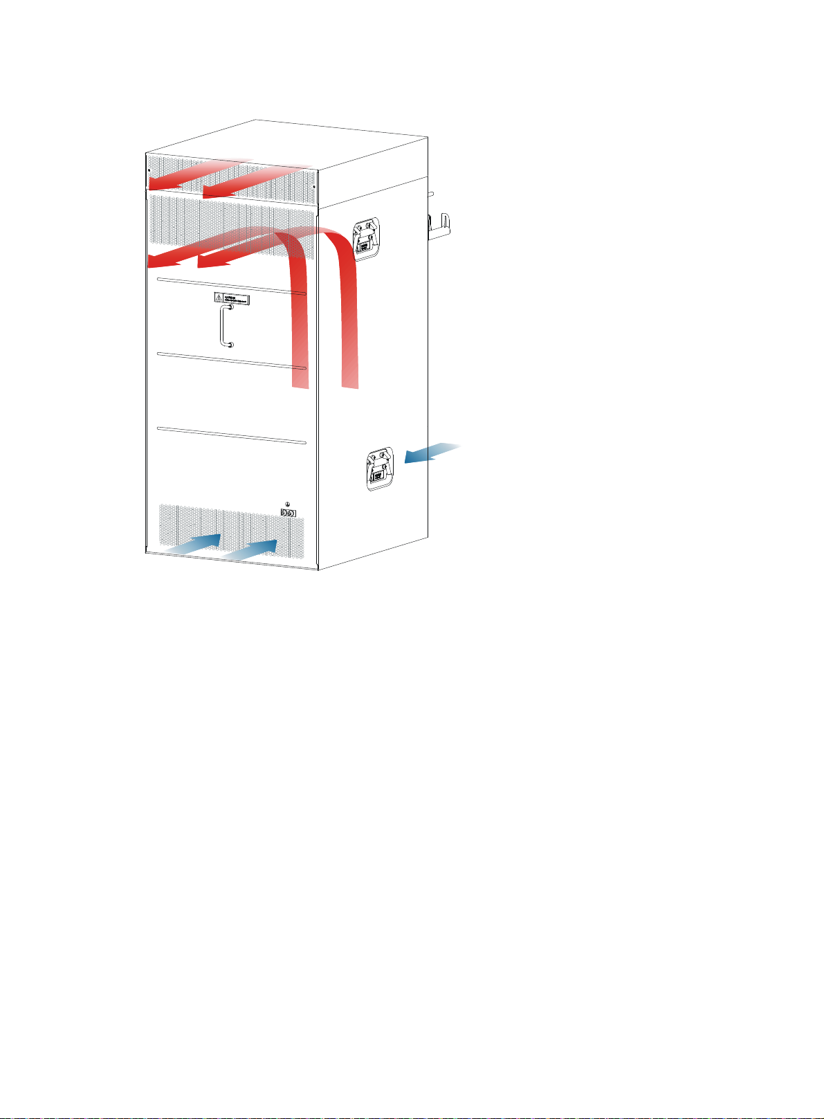
Figure 3 Airflow through the HSR6808 chassis
EMI
Electromagnetic interference (EMI) might be coupled from the source to the router through the following
coupling mechanisms:
• Capacitive coupling
• Inductive coupling
• Radiative coupling
• Common impedance coupling
• Conductive coupling
To prevent EMI, take the following actions:
• Take measures against interference from the power grid.
• Do not use the router together with the grounding equipment or lightning-prevention equipment of
power equipment, and keep the router far away from them.
• Keep the router far away from high-power radio launchers, radars, and equipment with high
frequency or high current.
• Use electromagnetic shielding when necessary.
7
Page 14
Lightning protection
To protect the router from lightning better, do as follows:
• Make sure the grounding cable of the chassis is well grounded. For how to connect the grounding
cable, see "Grounding the router."
• Make sure the grounding terminal of the AC power receptacle is well grounded.
• Install a lightning arrester at the input end of the power supply to enhance the lightning protection
capability of the power supply.
• Install a special lightning arrester at the input end of outdoor signal lines (for example, E1 line) to
which interface modules of the router are connected to enhance the lightning protection capability.
Space
• Because the router is heavy, install the router to the rack with the rack shelf.
• For ease of installation and maintenance, reserve at least 1 m (3.28 ft) of clearance between the
rack and walls or other devices.
• For heat dissipation, make sure the headroom in the equipment room is no less than 3 m (9.84 ft),
and an appropriately sized air conditioner is provided.
Power supply
• Make sure the power supply system at the installation site is stable and meets the requirements of
the power modules, including the rated input voltage.
• Select power modules based on the power consumption of the cards and fan trays. For more
information about system power consumption and technical specifications of power modules, see
"Power consumption," an
d "Power module."
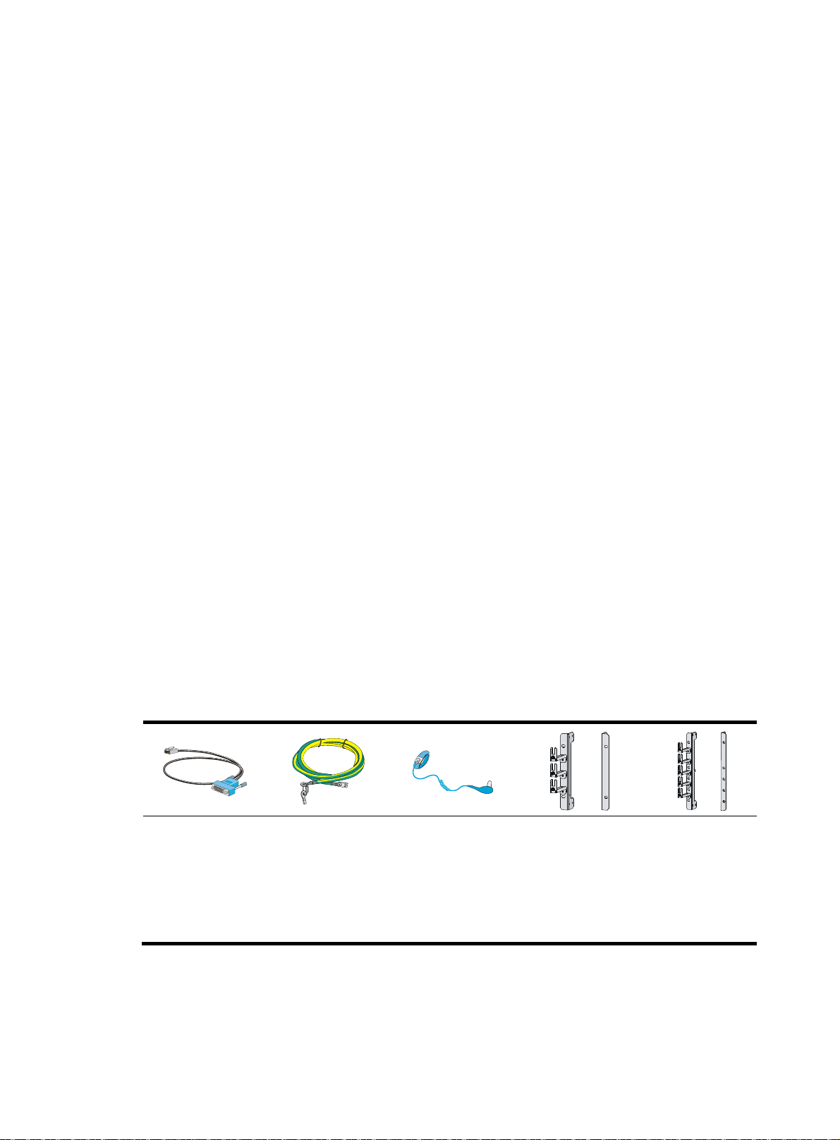
Installation accessories
Console cable
(supplied with the
router)
Grounding cable
(supplied with the
router)
ESD wrist strap
(supplied with the
router)
Mounting bracket
and cable
management bracket
for the HSR6802
(supplied with the
router)
Mounting bracket
and cable
management
bracket for the
HSR6804
(supplied with the
router)
8
Page 15
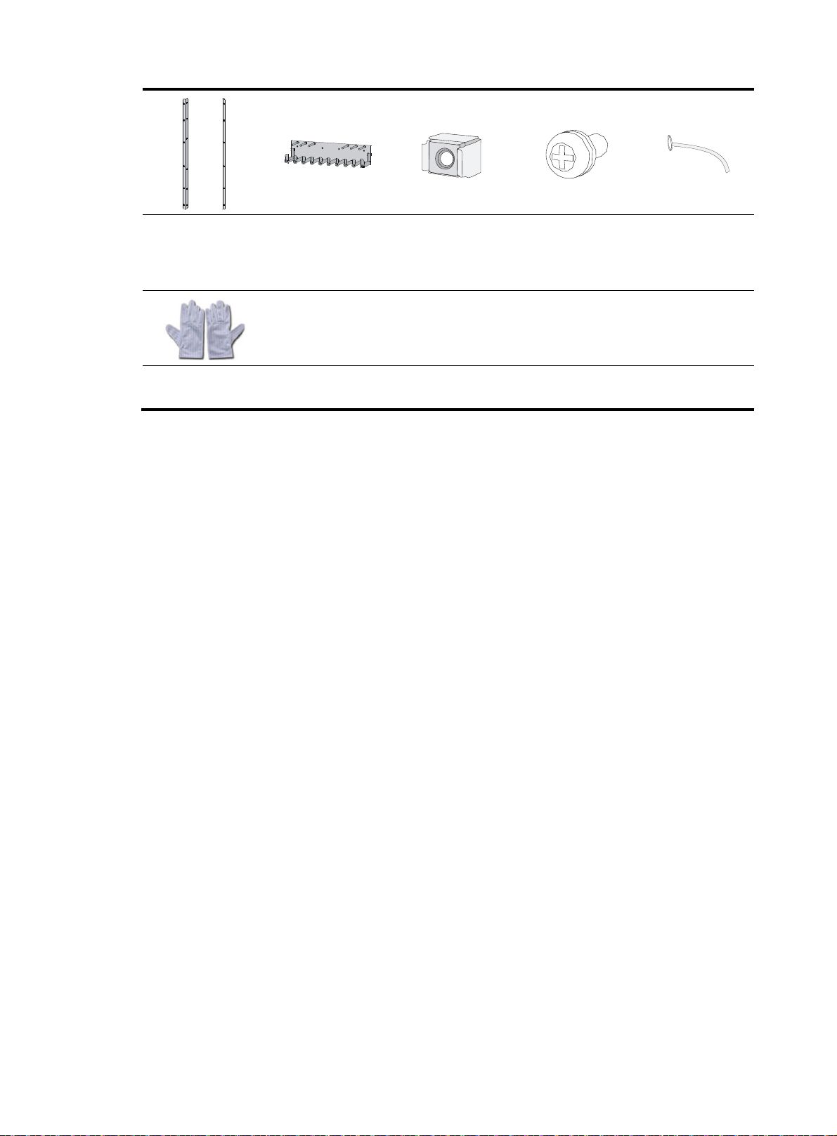
Mounting brackets
for the HSR6808
(supplied with the
router)
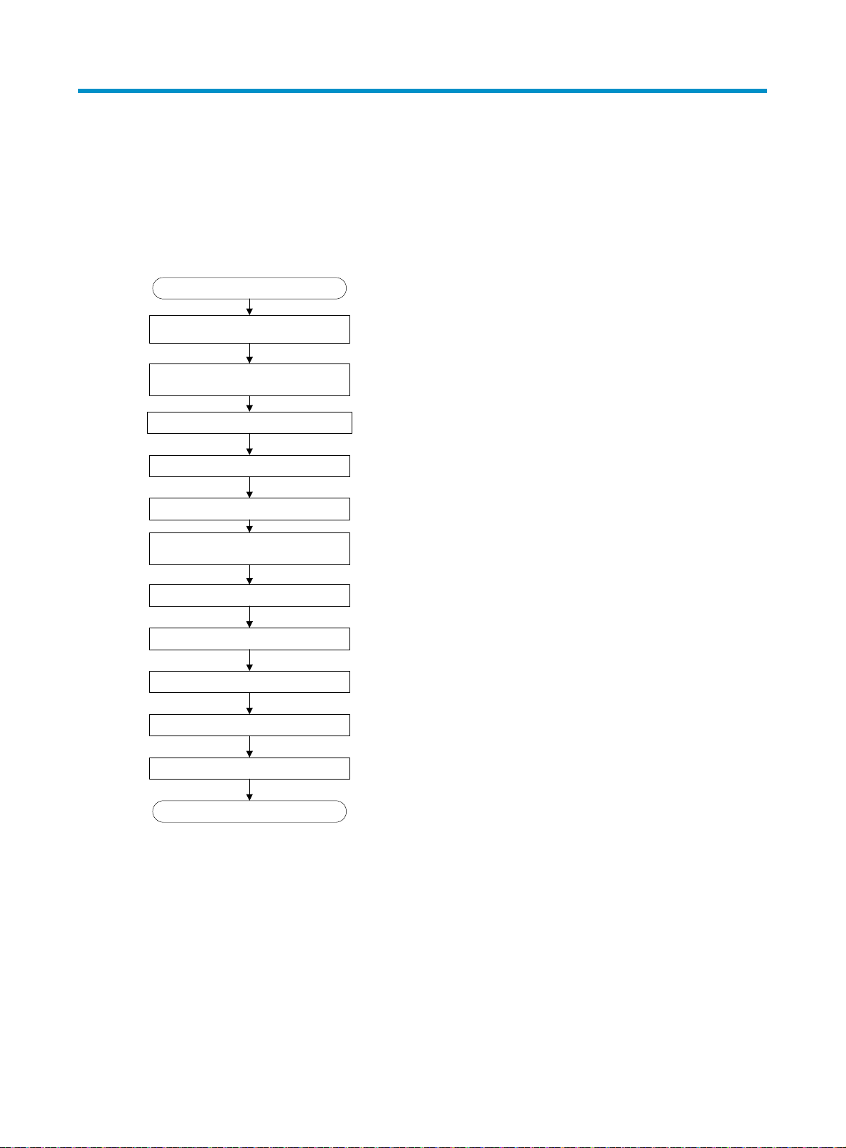
ESD gloves
(user-supplied)
Cable management
bracket for the
HSR6808 (supplied
with the router)
M6 cage nut
(supplied with the
router)
M6 screws (supplied
with the router)
Cable tie
(user-supplied)
9
Page 16
Installing the router
Installation flow
Figure 4 Installation flow
Start
Unpacking the router
Install a cable management bracket
(only on HSR6808 router)
Install the router to a 19-inch rack
Ground the router
Install a power module
Install an MPU and a switching fabric
Install optional components
module
Install an LPU
Install a HIM/MIM
Install a CF card
Connect the power cord
End
Installing a cable management bracket
The cable management brackets of the HSR6802 and HSR6804 are provided with mounting brackets.
You need to install a cable management bracket for an HSR6808 router.
To install a cable management bracket:
1. Face the front of the router.
2. Align the screw holes on the cable management bracket with the screw holes on the front panel of
chassis, and use a Phillips screwdriver to fasten the screws.
10
Page 17
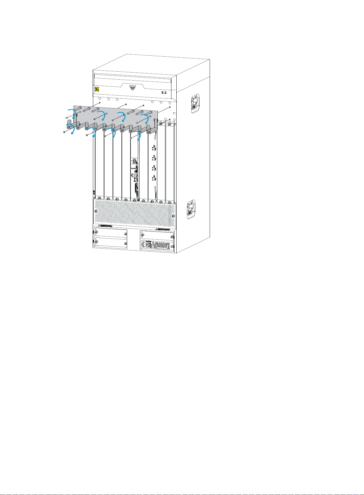
Figure 5 Installing a cable management bracket
Installing the router in a 19-inch rack
The procedures for installing an HSR6800 router in a rack are similar. This section uses an HSR6802
router as an example.
To install the router in a rack, you need mounting brackets and a rack shelf.
Installing cage nuts to the rack
1. Locate the installation position for the router and then install a rack shelf to the rack.
2. As shown in Figure 6, align the bottom of the front moun
the installation positions of cage nuts on the front rack posts.
ting bracket with the rack shelf and mark
11
Page 18
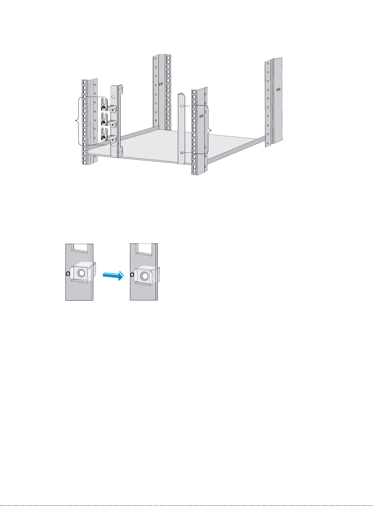
Figure 6 Marking the positions of cage nuts
5RU
5RU
3. Insert one edge of a cage nut into the hole.
4. Use a flat-blade screwdriver to compress the other edge of the cage nut, and then push the cage
nut fully into the hole.
5. Repeat steps 3 and 4 to install other cage nuts to all the marked positions on the rack post.
Figure 7 Installing a cage nut
Installing the mounting brackets to the router
If you have ordered an air filter, install it to the router before you install the mounting brackets. For the
installation procedure, see "Installing an air filter."
Be
fore you install the router to a rack, install the front mounting brackets to the left and right sides of the
router.
To install the front mounting brackets to the router, align the screw holes on the mounting brackets with the
screw holes on the left and right sides of the chassis, and then use a Phillips screwdriver to fasten the
screws.
12
Page 19
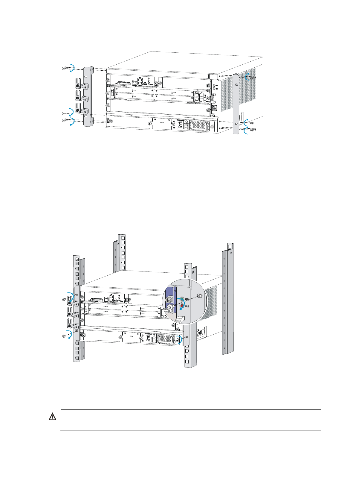
Figure 8 Installing the front mounting brackets to the two sides of the router
W
Installing the router in a 19-inch rack
1. Put the router on the rack shelf.
2. Slide the router into the rack so the screw holes on the mounting brackets are aligned with holes
that are installed with cage nuts on the rack posts.
3. Use M6 screws to attach the mounting brackets to the rack posts. Make sure the rack shelf is even
and stable.
Figure 9 Installing the router in a rack
Grounding the router
ARNING!
Correctly connecting the router grounding cable is crucial to lightning protection and EMI protection.
To connect the grounding cable:
13
Page 20
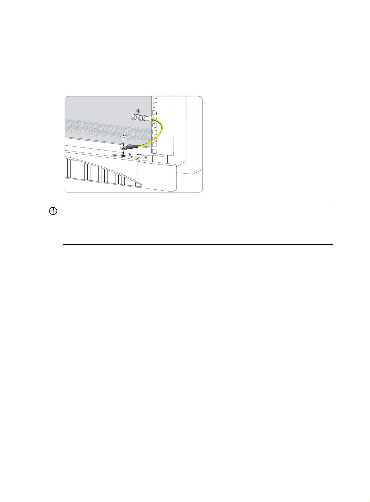
1. Remove the two grounding screws from the rear panel of the chassis.
2. Attach the grounding screw to the OT terminal of the grounding cable.
3. Use a Phillips screwdriver to fasten the grounding screw into the grounding screw hole.
4. Connect the other end of the grounding cable to the grounding strip of the rack.
Figure 10 Connecting the grounding cable to the grounding hole of router
IMPORTANT:
• The resistance reading should be smaller than 5 ohms between the chassis and the ground.
• To guarantee the grounding effect, use the grounding cable provided with the router to connect to the
grounding strip in the equipment room as long as possible.
Installing a power module
Each of an HSR6802 and an HSR6804 router provides two power module slots. An HSR6808 router
provides four power module slots. Slots except the Slot 1 (PWR1) are provided with filler panels. The
routers support both AC (PSR650-A and PSR1200-A) and DC (PSR650-D and PSR1200-D) power
modules, but AC and DC power modules cannot work together. The power modules in use must be of the
same specification.
Before you install the power module, make sure the power switch is off and the grounding cable is well
grounded.
The procedures for installing power modules are the same. This section uses a PSR650-A as an example.
To install a power module:
1. Face the front of the router and locate the slot to be used.
2. Loosen the captive screws with a Phillips screwdriver to remove the filler panel from the slot.
Keep the removed filler panel for future use.
Skip this step if you install the power module to the PWR1 slot.
3. Holding the handle of the power module with one hand and supporting the bottom of the power
module with the other hand, insert the power module slowly along the slide rails until it makes close
contact with the backplane.
4. Use a Phillips screwdriver to fasten the captive screws on the two sides of the power module.
For more information about the power module LED description, see "Power module LEDs."
14
Page 21
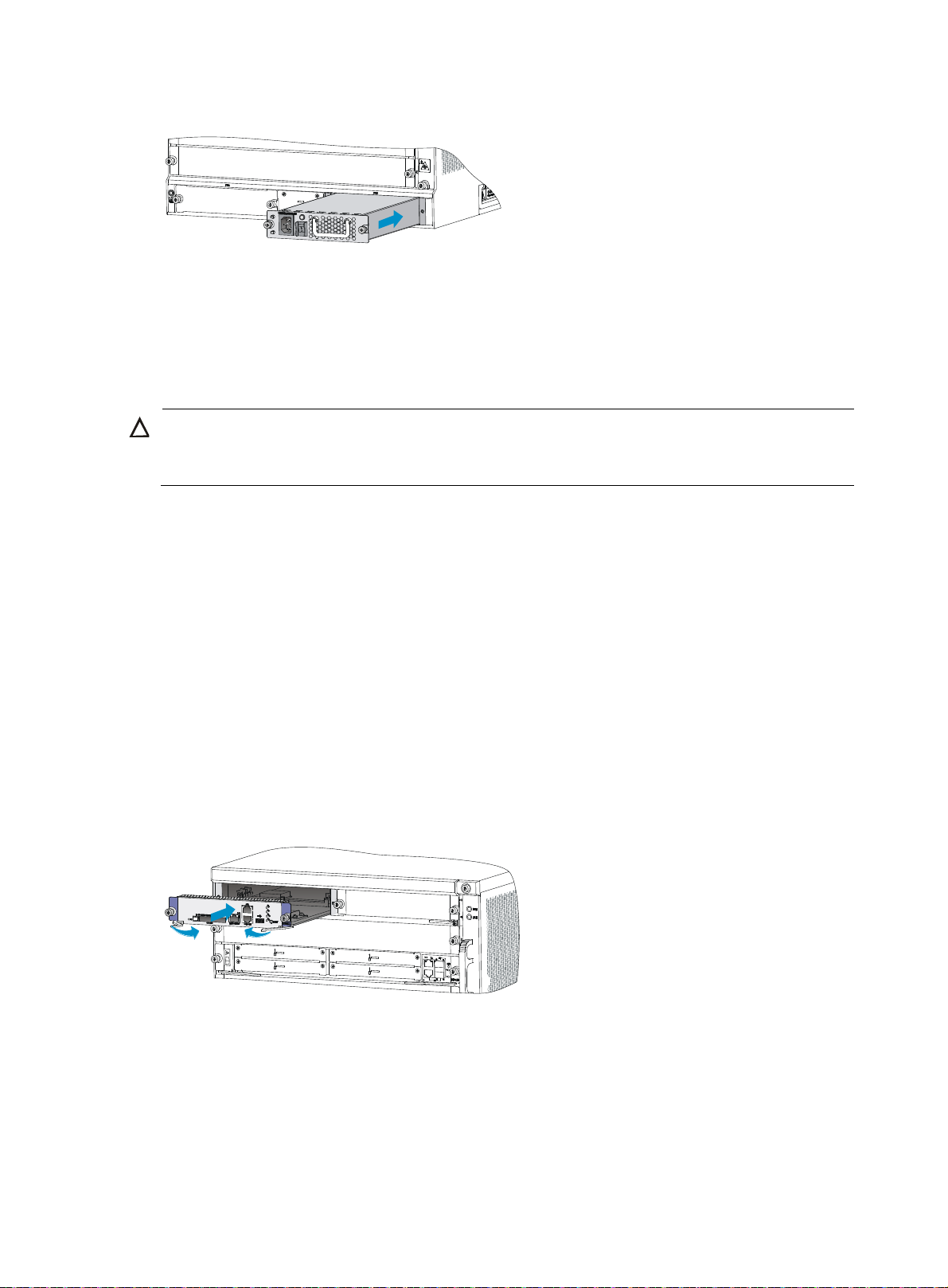
Figure 11 Installing a power module
g
Installing an MPU and a switching fabric module
Installing an RSE-X2 MPU
CAUTION:
The RUN LED flashes fast when the MPU is starting up. Do not install or remove the MPU durin
Otherwise, hardware might be damaged.
Before the installation, make sure the ejector levers of the MPU are outwards.
The Slot 4 of the HSR6808 is not provided with a filler panel.
this period.
To install an RSE-X2 MPU:
1. Face the front of the router and locate the slot to be used.
2. Loosen the captive screws with a Phillips screwdriver to remove the filler panel from the slot.
Keep the removed filler panel for future use.
Skip this step if you install the MPU to the Slot 4 of an HSR6808 router.
3. Insert the MPU slowly along the slide rails until it makes close contact with the backplane, and then
push the ejector levers inward to lock the MPU in position.
4. Use a Phillips screwdriver to fasten the captive screws on the two sides of the MPU.
For the MPU LED description, see "MPU and switching fabric module LEDs."
Figure 12 Installing an MPU
Installing an SFE-X1 switching fabric module
Only the Slot 6 of the HSR6808 supports the SFE-X1 switching fabric module.
Before the installation, make sure the ejector levers of the SFE-X1 are outwards.
To install an SFE-X1:
15
Page 22

1. Face the front of the router and locate the slot.
2. Loosen the captive screws with a Phillips screwdriver to remove the filler panel from the slot.
Keep the removed filler panel for future use.
3. Insert the SFE-X1 slowly along the slide rails until positioning pins on the backplane are seated in
the positioning holes, and then push the ejector levers inward to lock the SFE-X1 in position.
4. Use a Phillips screwdriver to fasten the captive screws on the two sides of the SFE-X1.
For the SFE-X1 LED description, see "MPU and switching fabric module LEDs."
Figure 13 Installing an SFE-X1
Installing an LPU
CAUTION:
The RUN LED flashes fast when the FIP is starting up. Do not install or remove a HIM/MIM during this
period. Otherwise, hardware might be damaged.
Slot 3 of the HSR6802/HSR6804 and Slot 7 of the HSR6808 are not provided with filler panels.
Before the installation, make sure the ejector levers of the LPU are outwards.
The procedures for installing LPUs are similar. This section uses a FIP-210 as an example.
16
Page 23
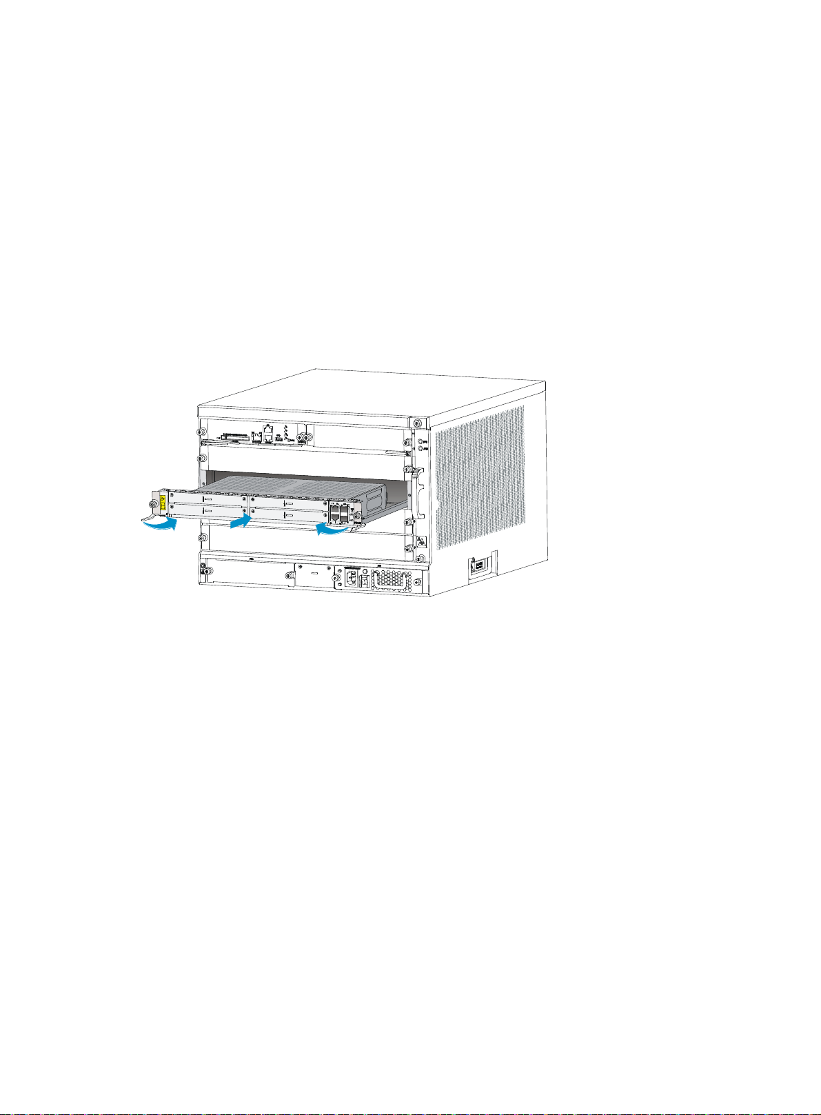
To install a FIP-210:
1. Face the front of the router and locate the slot to be used.
2. Loosen the captive screws with a Phillips screwdriver to remove the filler panel from the slot.
Keep the removed filler panel for future use.
Skip this step if you install the FIP-210 to Slot 3 of the HSR6802/HSR6804, or Slot 7 of the
HSR6808.
3. Gently push the FIP-210 into the slot along the slide rails until positioning pins on the backplane
are seated in the positioning holes, and then push the ejector levers inward to lock the FIP-210 in
position.
4. Use a Phillips screwdriver to fasten the captive screws on the two sides of the FIP-210.
For more information about the FIP LED description, see "FIP LEDs."
Figure 14 Inserting a FIP
Installing a HIM/MIM
The procedures for installing HIMs and MIMs are similar. This example installs a MIM to a FIP-210.
To install a MIM:
1. Face the front of the router and locate the slot to install the MIM on the FIP-210.
The MIM should be installed in the lower slot on the FIP-210.
2. Loosen the captive screws with a Phillips screwdriver to remove the filler panel from the slot.
Keep the removed filler panel for future use.
3. Holding the handle of the MIM with one hand, push the MIM slowly along the slide rails into the
slot until the MIM is fully seated.
4. Use a flat-blade screwdriver to fasten the captive screws on the MIM.
17
Page 24
Figure 15 Pushing the MIM into the slot
Installing a CF card
1. Push the CF card eject button all the way into the slot, and make sure the button does not project
from the panel.
2. Insert the CF card into the slot following the direction shown in Figure 16, and
not project from the slot.
Figure 16 Inserting the CF card into the slot
Installing optional components
Optional components (including the air filter) are not provided with the router. Purchase them if
necessary.
Installing an air filter
make sure it does
Installing an air filter on an HSR6802/HSR6804
The methods for installing air filters on the HSR6802 and HSR6804 are the same. This section uses an
HSR6804 as an example.
To install an air filter:
1. Face the left side (side of the inlet vents) of the router.
18
Page 25
2. Install the upper and lower slide rails on the chassis as shown in Figure 17.
3. Use a Phillips screwdriver to fasten the fastening screws on the upper and lower slide rails.
Figure 17 Installing the upper and lower slide rails
4. Push the air filter along the slide rails from the rear side of the chassis to the front.
Figure 18 Inserting the air filter to the slide rail
5. Use a Phillips screwdriver to fasten the captive screws on the rear side of the air filter.
19
Page 26
Figure 19 Fastening the captive screws
Installing an air filter on an HSR6808
1. Face the front of the router.
2. Align the positioning pins on the air filter with the screw holes on the inlet vent area, and use a
Phillips screwdriver to fasten the screws on the air filter.
Figure 20 Installing an air filter on an HSR6808
Connecting the power cord
Connecting an AC power cord
1. Make sure the router is well grounded, and the power switch on the router is in the OFF position.
2. Connect one end of the AC power cord to the AC receptacle on the router, and the other end to
the AC power source.
3. Use cable ties to secure the power cord to the rack post.
20
Page 27
Figure 21 Connecting an AC power cord to the router
W
Connecting DC power cords
Connecting power cords for the PSR650-D
ARNING!
To avoid connection mistakes, identify the label on the DC power cord.
Figure 22 DC power cords
To connect DC power cords:
1. Switch off the power supply.
2. Remove the protection cover of the DC power module, and use a Phillips screwdriver to remove the
screws from the DC-input terminal block.
3. Connect the end marked with "– " to the negative terminal (–) on the DC-input terminal block and
fasten the screw.
4. Connect the end marked with "+" to the positive terminal (+) on the DC-input terminal block and
fasten the screw.
5. Connect the other end of each DC power cord to the DC power source.
6. Install the protection cover of the DC power module.
21
Page 28
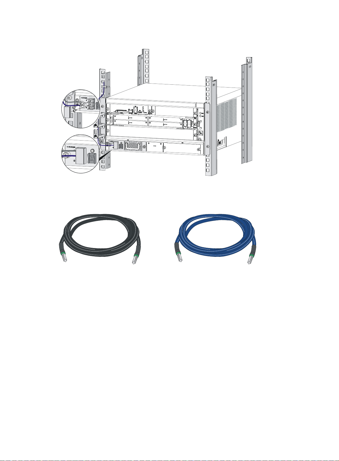
Figure 23 Connecting DC power cords
Connecting power cords for the PSR1200-D
Figure 24 DC power cords
+
To connect DC power cords:
1. Loosen the captive screws on the power module with a Phillips screwdriver to remove the power
module connector.
22
-
Page 29
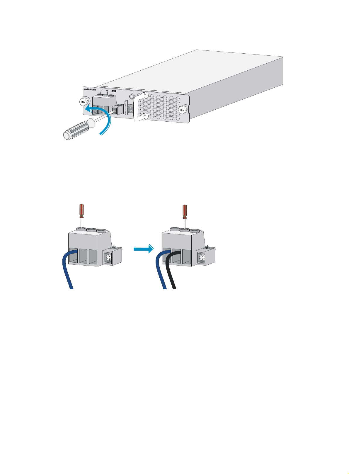
Figure 25 Removing the power module connector.
2. Connect the end marked with "– " to the negative terminal (–) on the power module connector and
fasten the fastening screw.
3. Connect the end marked with "+"to the positive terminal (+) on the power module connector and
fasten the fastening screw.
Figure 26 Attaching the power cords to the power module connector
4. Insert the power module connector in right direction into the power module, and fasten the captive
screws with a Phillips screwdriver.
23
Page 30

Figure 27 Installing the power module connector to the power module
5. Connect the other end of each power cord to the DC power source.
6. Use cable ties to secure the power cords to the rack post.
24
Page 31

Connecting interface cables
Connecting the AUX cable
Overview
An AUX cable has a crimped RJ-45 connector at one end for connecting to the AUX port of the router,
and D9 male connectors at the other end for connecting to the serial port of the modem.
Figure 28 AUX cable
Connecting the AUX cable
1. Plug the D9 male connector at one end of the AUX cable into the serial port of the modem.
2. Plug the RJ-45 connector of the AUX cable into the AUX port of the router.
Figure 29 Connecting the AUX port to a modem
25
Page 32

Connecting an Ethernet cable
Overview
10/100 Mbps Ethernet uses category-5 twisted pair cables, while 1000 Mbps Ethernet uses category-5
enhanced or category-6 twisted pair cables. Twisted pair cables include straight-through cables and
crossover cables.
Category-5 cables provide a transmission frequency of 100 MHz for voice and data transmission; they
are mainly used in 100Base-T and 10Base-T networks. Category-5 cables are common Ethernet cables,
which can also be used to transmit 1000 Mbps Ethernet data.
Category-5 enhanced cables feature low attenuation and crosstalk, providing higher attenuation to
crosstalk ratio (ACR), less delay error and higher performance than category-5 cables. Category-5
enhanced cables are mainly used in 1000 Mbps Ethernet networks.
Category-6 cables provide a transmission frequency of 1 MHz to 250 MHz, and improve the
performance on crosstalk and return loss. A fine better return loss performance is extremely important for
new-generation full-duplex high-speed networks. Category-6 cables have sufficient power sum ACR
(PS-ACR) when working at 200 MHz. They provide a bandwidth two times than that of category-5
enhanced cables, thus featuring a higher transmission performance. Therefore, category-6 cables are
suitable for applications requiring a transmission speed of more than 1 Gbps.
The 10/100 Mbps Ethernet uses two pairs of cables, orange/white, orange, green/white and green
cables, to transmit and receive data, while the 1000 Mbps Ethernet uses four pairs of cables to transmit
and receive data.
An Ethernet twisted pair cable connects network devices through the RJ-45 connectors at the two
ends. Figure 30 sh
Figure 30 RJ-45 connector pinout
PIN #8
PIN #1
EIA/TIA cabling specifications define two standards, 568A and 568B, for cable pinouts.
• Standard 568A—Pin 1: white/green stripe, pin 2: green solid, pin 3: white/orange stripe, pin 4:
blue solid, pin 5: white/blue stripe, pin 6: orange solid, pin 7: white/brown stripe, pin 8: brown
solid.
• Standard 568B—Pin 1: white/orange stripe, pin 2: orange solid, pin 3: white/green stripe, pin 4:
blue solid, pin 5: white/blue stripe, pin 6: green solid, pin 7: white/brown stripe, pin 8: brown
solid.
Ethernet twisted pair cables can be classified into straight-through and crossover cables based on their
pinouts.
ows the pinouts of an RJ-45 connector.
26
Page 33

For the pinouts of the twisted pair cables, see the following tables. (A and B represent the two ends of a
cable, respectively.)
Table 7 Straight-through cable pinouts
Pinout No. A B
1 Orange/white
2 Orange
3 Green/white
4 Blue
5 Blue/white
6 Green
7 Brown/white
8 Brown
Table 8 Crossover cable pinouts
Pinout No. A B
1 Orange/white
2 Orange
3 Green/white
4 Blue
5 Blue/white
Orange/white
Orange
Green/white
Blue
Blue/white
Green
Brown/white
Brown
Green/white
Green
Orange/white
Blue
Blue/white
6 Green
7 Brown/white
8 Brown
NOTE:
Strictly follow the pinouts in the above tables when identifying or making the two types of Ethernet cables.
Otherwise, the communication quality might be affected.
Making an Ethernet cable
1. Cut the cable to a required length with the crimping pliers.
2. Strip off an appropriate length of the cable sheath. The length is typically that of the RJ-45
connector.
3. Untwist the pairs so that they can lay flat, and arrange the colored wires based on the wiring
specifications.
4. Cut the top of the wires even with one another. Insert the wires into the RJ-45 end and make sure
the wires extend to the front of the RJ-45 end and make good contact with the metal contacts in the
RJ-45 end and in the correct order.
5. Crimp the RJ-45 connector with the crimping pliers until you hear a click.
Orange
Brown/white
Brown
6. Use a cable tester to verify the correct connectivity of the cable.
27
Page 34

Connecting an Ethernet cable
1. Plug one end of an Ethernet twisted pair cable into the copper Ethernet port (RJ-45 port) or the
management Ethernet port to be connected on the router and the other end of the cable into the
Ethernet port of the peer device. The 10/100/1000Base-T copper ports of the router support
MDI/MDI-X auto-sensing. They are connected to the network through category-5 or above twisted
pairs that are equipped with RJ-45 connectors.
2. Examine the status LED of the Ethernet ports. For more information about the LED status, see
"Appendix B LEDs."
Connecting a fiber cable
Transceiver module overview
When you use a fiber port, you need an SFP, XFP, or SFP+ transceiver module and a fiber cable with an
LC connector. For the compatibility between the cards and transceiver modules, see HP HSR6800
Routers Interface Module Guide.
Figure 31 SFP transceiver module
Figure 32 XFP transceiver module
28
Page 35

Figure 33 SFP+ transceiver module
g
Fiber cable overview
CAUTION:
• Never exert a fierce force when you insert or remove a fiber connector.
• Never pull, press or extrude the fiber fiercely.
Optical fibers can be classified into single-mode optical fibers and multi-mode optical fibers. A
single-mode optical fiber carries only a single ray of light, and a multi-mode optical fiber carries multiple
modes of lights.
Table 9 Characteristics of single-mode and multi-mode optical fibers
Item Sin
Core Small core (10 micrometers or less)
Dispersion Less dispersion
Light source and transmission
distance
le-mode optical fiber
Users lasers as the light source often
within campus backbones for distance
of several thousand meters
Multi-mode optical fiber
Larger core than single-mode
optical fiber (50 micrometers, 62.5
micrometers or greater)
Allows greater dispersion and
therefore, signal loss exists
Uses LEDs as the light source often
within LANs or distances of a
couple hundred meters within a
campus network
Table 10 lists the allowed maximum tensile load and crush load for the fiber.
Table 10 Allowed maximum tensile force and crush load
Period of force Tensile load (N)
Short period 150 500
Long term 80 100
Crush load (N/mm)
Fiber connectors are indispensable passive components in an optical fiber communication system. They
allow the removable connection between optical channels, which makes the optical system debugging
and maintenance more convenient. There are multiple types of fiber connectors. Figure 34 sh
ows an LC
connector. Fiber ports of the HP HSR6800 routers support only LC connectors.
29
Page 36

Figure 34 LC connector
W
g
1
(1) LC connector (2) Optical fiber
Connecting a fiber cable
ARNING!
Do not stare into any fiber port when you connect an optical fiber. The laser li
fiber might hurt your eyes.
2
ht emitted from the optical
To connect a fiber cable:
1. Remove the dust plug from a fiber port of the router.
2. Remove the dust cover from the transceiver module, and plug the end without a pull latch into the
fiber port.
3. Remove the dust cover from the fiber connector.
4. Identify the Rx and Tx ports. Plug the LC connector at one end of one fiber cable into the Rx port
of the router and the LC connector at the other end into the Tx port of the peer device. Plug the LC
connector at one end of another fiber cable into the Tx port of the router and the LC connector at
the other end to the Rx port of the peer device.
30
Page 37

Figure 35 Connecting a fiber cable
5. Examine the LINK LED after connection.
{ If the LED is on, the optical fiber link is present.
{ If the LED is off, no link is present. This might be because the TX and Rx port of the optical fiber
are not connected correctly. In this case, connect the optical fiber again.
Connecting an E1/T1 cable
Overview
E1 cable
You can use an 8E1 interface cable to connect to MIM-8E1(75)/MIM-8E1(75)-F modules.
Figure 36 8E1 splitter cable
31
Page 38

NOTE:
W
w
T1 cable
The coaxial connector and 75-ohm E1 adapter cable are optional accessories, and must be purchased
separately if needed.
CAUTION:
• When connecting the interface cable, pay attention to the mark on the interface to avoid wrong
insertion, which might damage the interface module or even the router.
• HP recommends that you install a lightning protector at the input end of the 8T1 cables to protect them
against lightning strikes more efficiently when they are led outdoors.
You can use an 8T1 interface cable to connect to MIM-8T1/MIM-8T1-F modules.
Figure 37 8T1 splitter cable
Connecting an E1/T1 cable
Connecting an E1 cable (D68 <----> BNC)
CAUTION:
hen connecting the interface cable, pay attention to the mark on the interface to avoid wrong insertion,
hich might damage the interface module or even the router.
• If you do not need to extend the cable, you can directly connect the BNC connectors of the E1
75-ohm cable to the remote network device as follows.
a. Connect the D68 connector of the E1 75-ohm cable to the D68 interface of the interface
module and fasten the bolts to fix the cable.
b. The other end of the cable provides one pair or multiple pairs of 75-ohm BNC connectors.
Connect the TX connectors and the RX connectors on this end to the RX connectors and the TX
connectors on the remote device respectively.
32
Page 39

Figure 38 Connecting an E1 75-ohm cable
……
• If you want to extend the cable, connect each BNC connector of the E1 75-ohm cable to one end
of a coaxial connector, and connect the remote device to the other end of the coaxial connector
through an E1 75-ohm adapter cable.
Figure 39 Connecting an E1 75-ohm cable
• If the impedance of the E1 interface on the remote device is 120 ohms, you must use an impedance
converter to adapt the impedance.
Figure 40 Connecting an impedance converter
E1 / E1-F
(75ohm)
Connecting a T1 cable
1. Connect the D68 connector of the 8-port T1 cable to the D68 interface on the interface module and
fasten the bolts to fix the cable.
E1 75-ohm cable
RX
TX
Impedance converter
Straight-through cable
Device
(120ohm E1 Port)
33
Page 40

2. The other end of the cable provides eight RJ-45 connectors. Connect them to the RJ-45 interface on
t
the remote device as needed.
Figure 41 Connecting an 8T1 cable
Connecting a CE3/CT3 cable
Overview
CAUTION:
HP recommends that you install a special lightning protector at the input end of the E3/T3 cables to protec
them against lightning strikes more efficiently when they are routed outdoors.
You can use a E3/T3 interface cable to connect the MIM-1CE3 and MIM-1CT3 modules.
Figure 42 E3/T3 cable
Connecting a CE3/CT3 cable
1. Connect the SMB connector of an E3/T3 cable to the Tx port on the interface module and the other
end to the Rx port on the device to be connected.
2. Connect the SMB connector of another E3/T3 cable to the Rx port of interface module and the
other end to the Tx port on the device to be connected.
34
Page 41

Figure 43 Connecting a CE3/CT3 cable
Connecting a serial port cable
Overview
You can use a serial port cable to connect to the MIM-2SAE/MIM-4SAE/MIM-8SAE module. Select a
serial port cable according to the link type.
Figure 44 V.24 DTE cable
Figure 45 V.24 DCE cable
35
Page 42

Figure 46 V.35 DTE cable
Figure 47 V.35 DCE cable
A
Pos.28
A
X1
Pos.1
Figure 48 X.21 DTE cable
A
Pos.1
A
Pos.15
X2
Figure 49 X.21 DCE cable
B
W
B
X2
B
Pos.1
W
X1
B
Pos.28
36
Page 43

Figure 50 RS449 DTE cable
Figure 51 RS449 DCE cable
Figure 52 RS530 DTE cable
Figure 53 RS530 DCE cable
Connecting a serial port cable
1. Check port type of the peer device and choose the synchronous serial interface cable of correct
type.
2. Plug the D28 end of the synchronous serial interface cable into the D28 interface of the SAE
interface module.
3. If the WAN uses DDN line, connect the cable to the port of the CSU/DSU.
37
Page 44

4. Identify the LINK LED on the SAE panel.
{ If the LED is on, a link is present.
{ If the LED i s off, a fault has occurred on the link and signal is out of synchronization. In this case,
examine the link.
38
Page 45

Accessing the router
W
Login methods
The following logins methods are available for you to log in to the router:
• Logging in through the console port, which is the most common way to log in to a router and also
the prerequisite for configuring other login methods.
• Logging in through Telnet or SSH.
• Logging in through the AUX port.
Logging in through the console port
You can log in only through the console port the first time you log in to your router.
Before you log in to the router, prepare an 8-core shielded cable, with a crimped RJ-45 connector at one
end, and a DB-9 male connector at the other end, and a PC with the operating system Windows
95/98/NT/2000/XP/7. This section uses a PC with Windows XP as an example.
Setting up a configuration environment
CAUTION:
hen you disconnect a PC from a powered-on router, disconnect the DB-9 connector of the console cable
from the PC after disconnecting the RJ-45 connector from the router.
1. Plug the DB-9 female connector to the serial port of the configuration terminal.
2. Connect the RJ-45 connector to the console port of the router.
39
Page 46

Figure 54 Connecting the console cable
Setting terminal parameters
1. Select Start > All Programs > Accessories > Communications > HyperTerminal.
The Connection Description dialog box appears.
Figure 55 Connection description
2. Select the serial port to be used from the Connect using list, and click OK.
40
Page 47

Figure 56 Setting the serial port used by the HyperTerminal connection
3. Set Bits per second to 9600, Data bits to 8, Parity to None, Stop bits to 1, and Flow control to None,
and click OK.
Figure 57 Setting the serial port parameters
4. Select File > Properties in the HyperTerminal window.
41
Page 48

Figure 58 HyperTerminal window
5. On the Settings tab, set the emulation to VT100 and click OK.
Figure 59 Setting terminal emulation in test Properties dialog box
42
Page 49

Powering on the router
Verifying before power-on
Before powering on the router, verify the following items:
• The power modules and fan trays are correctly installed.
• The power cord and grounding cable are correctly connected.
• The power source voltage meets the requirement of the router.
• The console cable is correctly connected, the terminal or PC used for configuration has started, and
the configuration parameters have been set.
• If a CF card is used, verify that the CF card is in position.
• Make sure the installed LPUs and HIMs/MIMs are in position.
Powering on the router
• Turn on the switch of the power supply system for the router.
• Turn on the switch of the AC or DC power modules.
Displaying boot information
Power on the router, and you can see the following information:
System is starting...
Booting Normal Extend BootWare........
The Extend BootWare is self-decompressing........................Done!
****************************************************************************
* *
* HP HSR68 BootWare, Version 0.17 *
* *
****************************************************************************
Copyright (c) 2010-2012 Hewlett-Packard Development Company, L.P.
Compiled Date : Apr 10 2012
CPU Type : P2020
CPU L1 Cache : 32KB
CPU Clock Speed : 1000MHz
Memory Type : DDR3 SDRAM
Memory Size : 4096MB
Memory Speed : 667MHz
Flash Size : 8MB
cfa0 Size : 999MB
NVRAM Size : 128KB
BASIC CPLD Version : 1.0
EXTEND CPLD Version : 1.0
PCB Version : Ver.A
43
Page 50

BootWare Validating...
Press Ctrl+B to enter extended boot menu...
Starting to get the main application file--cfa0:/HSR6800.bin!............
............................................................................
............................................................................
...
The main application file is self-decompressing.............................
............................................................................
............................................................................
............................................................................
....................................................................Done!
System application is starting...
Mainboard 1 is master.
User interface con1 is available.
Press ENTER to get started.
Press Enter, and the following prompt appears:
<HP>
You can now configure the router.
Logging in to the router through Telnet/SSH
1. After powering on the router, log in to the router through the console port.
2. Use the telnet server enable command and the ssh server enable command to enable the Telnet
and SSH function on the router, respectively, and use the user privilege level command to set the
user privilege level.
3. Connect the PC to the management Ethernet port or the copper Ethernet port on the router and
specify an IP address for the port.
4. Specify an IP address for the PC, making sure the PC and the port are in the same network
segment.
For more information about how to log in to the router through Telnet/SSH, see HP HSR6800 Routers
Configuration Guides.
Logging in to the router through the AUX port
1. After powering on the router, connect the console cable to the console port.
To configure the AUX port:
Step Command
1. Enter system view.
2. Enter AUX user interface view.
44
system-view
user-interface aux 0
Page 51

Step Command
3. Set the authentication mode.
authentication-mode none
4. Set the user privilege level.
2. Plug the D-9 female connector to the serial port of the configuration terminal or PC.
3. Connect the RJ-45 connector to the AUX port of the router. Then you can log in to the router through
the AUX port.
For more information about how to log in to the router through an AUX port, see HP HSR6800 Routers
Fundamentals Configuration Guides.
Configuring basic settings
Step Command
1. Set the current time and date.
2. Enter system view.
3. Enter Ethernet interface view.
4. Specify an IP address for the
interface.
clock datetime time date
system-view Available in user view.
interface interface-type
interface-number
ip address ip-address { mask-length
| mask } [ sub ]
user privilege level 3
Remarks
Optional.
Available in user view.
N/A
By default, no IP address is
assigned to any interface.
5. Return to system view.
6. Specify a static route.
7. Save the current configuration
to the startup configuration file
in the root directory of the
storage media.
8. Verify the running
configuration.
quit Available in any view.
ip route-static dest-address { mask |
mask-length } { next-hop-address |
interface-type interface-number
[ next-hop-address ] | vpn-instance
d-vpn-instance-name
next-hop-address } track
track-entry-number [ preference
preference-value ] [ tag tag-value ]
[ description description-text ]
save [ safely ] [ backup | main ]
[ force ]
display current-configuration Available in any view.
By default, the preference of a
static route is 60, tag is 0, and no
description is configured.
Available in any view.
45
Page 52

Replacement procedures
All modules of the HP HSR6800 routers are field replaceable.
Safety recommendations
1. Always wear an ESD wrist strap or ESD gloves when you replace the modules.
2. All transceiver modules are hot swappable. If you need to replace LPUs or HIMs/MIMs when the
router is powered on, use the command remove slot slot-number to stop them from working first.
3. When you replace FRUs, such as MPUs, LPUs, memory modules, the CF card, and HIMs/MIMs,
follow these guidelines:
{ Ensure good alignment with the slot to avoid damage to the module during installation or
removal.
{ Before removing a module, make sure the captive screws are completely loosened. Otherwise,
the panel of the module might be deformed.
{ Avoid touching any components on the PCB during observing or moving the module.
{ Put the removed module on an antistatic workbench with the PCB side facing upward or place
them in antistatic bags.
Replacing a power module
The replacement procedure of an AC power module is the same as a DC power module. This section
uses an AC power module as an example.
To replace a power module:
1. Face the front of the router and locate the power module to be removed.
2. Use a Phillips screwdriver to completely loosen the captive screws of the power module.
3. Holding the handle of the power module with one hand and supporting the bottom of the power
module with the other hand, gently pull the power module out of the slot along the slide rails.
Put the removed power module on an antistatic workbench or into an antistatic bag.
Figure 60 Pulling the power module out of the slot
4. Install a new power module. For the installation procedure, see "Installing a power module."
If you do not install a new power module in the slot, install a filler panel.
46
Page 53

Replacing an MPU and a switching fabric module
Prerequisites
• If the router is installed with only one MPU, make sure all power sources to the router are turned off
before replacing the MPU.
• If the router is installed with two MPUs, make sure both MPUs operate correctly before replacement.
{ To replace the active MPU, HP recommends that you execute the slave switchover command in
the system view of the active MPU to trigger an active and standby switchover. For more
information about the slave switchover command, see HP HSR6800 Routers High Availability
Command Reference.
{ To replace the standby MPU, you can remove it immediately.
Replacing an RSE-X2 MPU
1. Face the front of the router and locate the MPU to be removed.
2. Use a Phillips screwdriver to completely loosen the captive screws of the MPU.
3. Holding the ejector levers of the MPU with both hands, pull the ejector levers outward, and gently
pull the MPU out of the slot along the slide rails.
Figure 61 Pulling the RSE-X2 MPU out of the slot
4. Install a new MPU. For the installation procedure, see "Installing an RSE-X2 MPU."
If you do not install a new MPU in the slot, install a filler panel.
Replacing an SFE-X1
1. Face the front of the router and locate the SFE-X1 to be removed.
2. Use a Phillips screwdriver to completely loosen the captive screws on the SFE-X1.
3. Holding the ejector levers of the SFE-X1 with both hands, pull the ejector levers outward, and
gently pull the SFE-X1 out of the slot along the slide rails.
47
Page 54

Figure 62 Pulling the SFE-X1 out of the slot (HSR6808)
4. Install a new SFE-X1. For the installation procedure, see "Installing an SFE-X1 switching fabric
module."
If you do not install a new SFE-X1 in the slot, install a filler panel.
Replacing an LPU
CAUTION:
To avoid hardware damage, do not replace the LPU when its RUN LED is fast flashing.
To replace an LPU, for example, FIP-210:
1. Face the front of the router and locate the FIP module to be removed.
2. Use a Phillips screwdriver to completely loosen the captive screws of the FIP module.
3. Holding the ejector levers of the FIP module with both hands, pull the ejector levers outward, and
gently pull the FIP module out of the slot along the slide rails.
48
Page 55

Figure 63 Pulling the FIP module out of the slot
4. Install a new FIP module. For the installation procedure, see "Installing an LPU."
If you do not install a new FIP module in the slot, install a filler panel.
Replacing a HIM/MIM
The procedures for replacing HIMs and MIMs are similar. This example replaces a MIM to a FIP-210.
1. Face the front of the router and locate the MIM to be removed.
2. Use a flat-blade screwdriver to completely loosen the captive screws of the MIM.
3. Holding the handle of the MIM, gently pull the MIM out of slot along the slide rails.
Figure 64 Pulling the MIM out of the slot
4. Install a new MIM. For the installation procedure, see "Installing a HIM/MIM."
If you do not install a new MIM in the slot, install a filler panel.
49
Page 56

Replacing a CF card
CAUTION:
To avoid hardware damage, do not remove the CF card when the router is booting or the CF LED is
flashing.
To replace a CF card:
1. Press the CF card eject button of the CF card reader so that the eject button projects from the panel.
2. Press the eject button again to eject the CF card part-way out of the CF card reader, and then pull
the CF card out of the CF card reader.
Figure 65 Removing a CF card
3. Install a new CF card. For the installation procedure, see "Installing a CF card."
Replacing a transceiver module
1. Pressing the tab of the LC connector, pull out the LC connector from the transceiver module.
Put on the dust cap for the LC connector.
2. Pivot the clasp of the transceiver module down to the horizontal position.
3. Hold the clasp to gently pull the transceiver module out.
Put the dust plug on the removed module, and put the removed module into its original shipping
materials.
4. Install a new transceiver module. For the installation procedure, see "Connecting a fiber cable."
If you do not install a new transceiver module in the interface, install a dust-proof plug in the
interface.
Figure 66 Removing a transceiver module
50
Page 57

Replacing a fan tray
CAUTION:
• Keep your hands away from the spinning fan blades when removing the fan tray.
• Do not keep the router working without a fan tray for more than two minutes because poor ventilation
might result in damage to the router.
Replacing a fan tray for an HSR6802/HSR6804 router
The methods for replacing fan trays for the HSR6802 and HSR6804 are the same. This section uses an
HSR6804 as an example.
To replace a fan tray:
1. Face the front of the router.
2. Use a Phillips screwdriver to completely loosen the captive screws of the fan tray to be removed.
3. Holding the handle of the fan tray with one hand and supporting the bottom of the fan tray with the
other hand, gently pull the fan tray out of the slot along the slide rails.
Figure 67 Pulling out the fan tray
4. Holding the handle of the fan tray with one hand and supporting the bottom of the fan tray with the
other hand, gently push the fan tray into the slot along the slide rails until it is completely seated.
5. Use a Phillips screwdriver to fasten the captive screws on the fan tray.
Replacing a fan tray for an HSR6808 router
1. Face the front of the router.
2. Press the fan tray release button with the thumb, slightly pull the fan tray away from the chassis,
and slowly pull the fan tray out along the slide rails when fans stop spinning.
3. Holding the front part of the fan tray with one hand, pressing down the release button with the
thumb, and supporting the bottom of the fan tray with the other hand, push the fan tray into the slot
along the slide rails until the fan tray makes complete contact with the backplane.
51
Page 58

Figure 68 Pulling out the fan tray
Replacing an air filter
IMPORTANT:
You can clean the air filter with water, but wait until it is completely dry before installing it again.
Replacing an air filter for an HSR6802/HSR6804 router
1. Face the left side of the router.
2. Use a Phillips screwdriver to completely loosen the captive screws of the air filter.
Figure 69 Loosening the captive screws of the air filter
3. Gently pull the air filter out along the slide rails.
52
Page 59

Figure 70 Pulling the air filter out along the slide rails
4. Install a new air filter. For the installation procedure, see "Installing an air filter on an
HSR6802/HSR6804."
Replacing an air filter for an HSR6808 router
1. Face the front of the router.
2. Use a Phillips screwdriver to completely loosen the captive screws of the air filter.
Figure 71 Removing the air filter
3. Install a new air filter. For the installation procedure, see "Installing an air filter on an HSR6808."
Replacing a memory module
CAUTION:
Use the memory modules provided by HP only. Otherwise, the router might be unable to operate correctly.
The MPUs and LPUs are equipped with memory modules. Before you install or remove a memory module,
remove the MPU or LPU from the chassis first. For more information, see "Replacing an MPU and a
s
witching fabric module" and "Replacing an LPU."
53
Page 60

For the memory module specifications, see "Appendix A Chassis views and technical specifications."
Memory module structure
Figure 72 Memory module structure (DDR2)
(1) Connector edge (2) Polarization notch
(3) Latch notch
Figure 73 Memory module structure (DDR3)
(1) Connector edge (2) Polarization notch
(3) Latch notch
Replacing a memory module
The methods for replacing memory modules are similar. This example replaces a memory module on an
RSE-X2.
To replace a memory module:
1. Pull the release latches away from the memory module at both ends so that the memory module is
lifted from the memory module slot.
2. Holding the non-conductive edge, remove the memory module.
3. Align the polarization notch of the memory module with the key in the connector.
4. Insert the memory module into the slot.
54
Page 61

5. Carefully and firmly press the memory module at both ends until you hear a click. This indicates the
memory module is seated in the memory module slot.
6. Check that the release latches have firmly locked the memory module in position.
Figure 74 Replacing a memory module
55
Page 62

Hardware management and maintenance
The output depends on your router model and software version. For more information about the
commands used in this chapter, see HP HSR6800 Routers Command References.
Displaying the hardware information of the router
Displaying the version information of the router
Use the display version command to display software and hardware version information of the router.
The output includes the following information: the current software version and hardware version, router
operating time, type and operating time of each MPU and LPU.
<Sysname> display version
HP Comware Platform Software
Comware Software, Version 5.20, A2706P02
Copyright (c) 2010-2012 Hewlett-Packard Development Company, L.P.
HP HSR6808 uptime is 0 week, 0 day, 0 hour, 15 minutes
Slot 0: SAP-4EXP uptime is 0 week, 0 day, 0 hour, 13 minutes
CPU type: FREESCALE P4080 1500MHz
4096M bytes DDR3 SDRAM Memory
8M bytes Flash Memory
128K bytes NVRAM
PCB Version: Ver.A
Logic Version: 1.0
Basic BootWare Version: 1.06
Extend BootWare Version: 1.06
[FIXED PORT] XGE0/0/0 (Hardware)Ver.A, (Driver)1.0, (Cpld)1.0
[FIXED PORT] XGE0/0/1 (Hardware)Ver.A, (Driver)1.0, (Cpld)1.0
[FIXED PORT] XGE0/0/2 (Hardware)Ver.A, (Driver)1.0, (Cpld)1.0
[FIXED PORT] XGE0/0/3 (Hardware)Ver.A, (Driver)1.0, (Cpld)1.0
Slot 4: RSE-X2 uptime is 0 week, 0 day, 0 hour, 15 minutes
CPU type: FREESCALE P2020 1000MHz
4096M bytes DDR3 SDRAM Memory
8M bytes Flash Memory
128K bytes NVRAM
PCB Version: Ver.B
Basic Logic Version: 1.0
Extend Logic Version: 1.0
Basic BootWare Version: 1.01
Extend BootWare Version: 1.01
[FIXED PORT] CON (Hardware)Ver.B, (Driver)1.0, (Cpld)1.0
[FIXED PORT] AUX (Hardware)Ver.B, (Driver)1.0, (Cpld)1.0
56
Page 63

[FIXED PORT] MGE4/0/0 (Hardware)Ver.B, (Driver)1.0, (Cpld)1.0
Displaying the running statistics for the router
For diagnosis or troubleshooting, you can use separate display commands to collect running status data
module by module, or use the display diagnostic-information command to bulk collect running data for
multiple modules. This command displays the output of the display clock, display version, display device,
and display current-configuration commands.
• Save the operating statistics for each module of the router.
<Sysname> display diagnostic-information
Save or display diagnostic information (Y=save, N=display)? [Y/N]:y
Please input the file name(*.diag)[cfa0:/default.diag]:aa.diag
Diagnostic information is outputting to cfa0:/aa.diag.
Please wait...
Recv slot 4 response packet.
Save successfully.
Execute the more aa.diag command in user view, and then press the Page Up and Page Down
keys to view the contents of the file aa.diag.
• Display the operating statistics for each module of the router.
<Sysname> display diagnostic-information
Save or display diagnostic information (Y=save, N=display)? [Y/N]:n
=================================================
===============display clock===============
=================================================
08:54:16 UTC Fri 15/06/2012
===================================================
===============display version===============
===================================================
…
Displaying detailed information about a card
• Use the display device verbose command to display detailed information about all cards.
<Sysname>display device verbose
System-mode(Current/After Reboot): Normal/Normal
Slot No. Board type Status Primary SubSlots
-------------------------------------------------------------------- 0 N/A Absent N/A N/A
1 RSE-X2 Normal Master 0
2 N/A Absent N/A N/A
3 N/A Absent N/A N/A
4 FIP-110 Normal N/A 4
5 N/A Absent N/A N/A
Slot 4 : FIP-110(4 Subslots)
Subslot 1 : MIM-2GBE
57
Page 64

Subslot 2 : MIM-2GBE
p
• Use the display device slot slot-number command to display detailed information about the card in
the specified slot.
<Sysname> display device slot 1
System-mode(Current/After Reboot): Normal/Normal
Slot 1 : RSE-X2
SubSlot No. Card Type Status Max Ports
------------------------------------------------------- 1 Fixed SubCard Normal 3
Table 11 Command output
Field Descri
Slot No. Slot number of the card.
Card Type Card model. The value NONE indicates that no card is present in the slot.
Running status of the card:
tion
• Absent—No card is present in the slot.
Status
• Fault—The card in the slot is booting, or the card has failed and cannot boot
correctly.
• Normal—The card in the slot is operating correctly.
Max Ports Maximum number of ports that the card supports.
Displaying the electrical label data
Electrical label data is also called permanent configuration data or archive information, which includes
the card name, serial number, MAC address, and vendor name.
• Use the display device manuinfo command to display the electrical label data for the card in each
slot.
<Sysname> display device manuinfo
Slot 0:
DEVICE_NAME: RT-RSE-X2
DEVICE_SERIAL_NUMBER: 210231A1RG0000000002
MAC_ADDRESS: 00FE-1230-1230
MANUFACTURING_DATE: 2011-12-12
VENDOR_NAME:HP
• Use the display device manuinfo slot slot-number command to display the electrical label data for
the card in the specified slot.
<Sysname> display device manuinfo slot 0
Slot 0:
DEVICE_NAME: RT-RSE-X2
DEVICE_SERIAL_NUMBER: 210231A1RG0000000002
MAC_ADDRESS: 00FE-1230-1230
MANUFACTURING_DATE: 2011-12-12
VENDOR_NAME:HP
58
Page 65

Table 12 Command output
p
p
Field Descri
DEVICE_NAME Card type.
DEVICE_SERIAL_NUMBER Card serial number.
MAC address of the card:
MAC_ADDRESS
• An MPU has a MAC address.
tion
• An LPU does not have a MAC address, and the field displays NONE.
MANUFACTURING_DATE Manufacturing date of the card.
The operation is not supported on
the specified board or subslot
The display device manuinfo command is not supported on a card that is
virtualized through the MPU.
Displaying the CPU usage statistics
Use the display cpu-usage command to display the CPU usage statistics for all cards.
<Sysname> display cpu-usage
Slot 0 CPU usage:
2% in last 5 seconds
2% in last 1 minute
1% in last 5 minutes
Slot 5 CPU usage:
1% in last 5 seconds
1% in last 1 minute
1% in last 5 minutes
Table 13 Command output
Field Descri
CPU usage of the card in slot 0.
Slot 0 CPU usage
1% in last 5 seconds
1% in last 1 minute
1% in last 5 minutes
If the card in the slot has multiple CPUs, "Slot 0 CPU usage" displays the
usage of the master CPU of the card in slot 0, and "Slot 0 CPU 1 CPU
usage" displays the usage of the auxiliary CPU of the card in slot 0.
After a boot, the system calculates and records the average CPU usage rate
every five seconds.
This field displays the average CPU usage rate in the last five seconds.
After a boot, the system calculates and records the average CPU usage rate
every one minute.
This field displays the average CPU usage rate in the last minute.
After a boot, the system calculates and records the average CPU usage rate
every five minutes.
This field displays the average CPU usage rate in the last five minutes.
tion
Displaying the MPU memory usage
Use the display memory command to display the active MPU memory information.
59
Page 66

<Sysname> display memory
p
p
p
System Total Memory(bytes): 4069505360
Total Used Memory(bytes): 277820968
Used Rate: 6%
Table 14 Command output
Field Descri
System Total Memory(bytes) Physical memory size (in bytes) of the MPU.
Total Used Memory(bytes) Used memory size (in bytes) of the MPU.
Used Rate Memory usage of the MPU.
tion
Displaying the CF card information
Use the display device cf-card command to display the CF card information.
<Sysname> display device cf-card
Slot No. Dev No. Status Size(M)
---------------------------------------------- 0 0 Normal 999
0 1 Absent N/A
Table 15 Command output
Field Descri
Slot No. Slot number of the CF card.
Device number of the CF card:
Dev No.
• 0 for a built-in CF card.
• 1 for an external CF card.
tion
Operating status of the CF card:
Status:
• Absent—No CF card is present in the slot.
• Fault—The CF card has failed.
• Normal—The CF card is operating correctly.
Size: Storage capacity of the CF card.
Displaying the fan operating status
Use the display fan command to display the fan operating status.
<Sysname> display fan
Fan 1 State: Normal
Table 16 Command output
Field Descri
Fan 1 Number of the fan.
tion
60
Page 67

Field Description
p
Fan state:
State
• Normal—The fan is operating correctly.
• Absent—The fan is not in position.
• Fault—The fan has failed.
Displaying the power module operating status
Use the display power command to display the power module operating status.
<Sysname> display power
System Power Total : 650 watts
System Power Used : 275 watts
System Power Usable : 375 watts
Power No. Type Watts State ID
-------------------------------------------- 1 N/A N/A Absent N/A
2 AC 650 Normal 0
Table 17 Command output
Field Descri
System Power Total Total power provided by the power modules.
System Power Used Power in use.
System Power Usable Power available for use.
Power No. Slot number of the power module.
Power module type:
Type
• AC—AC power modules.
tion
• DC—DC power modules.
Watts Power provided by the power module.
ID Power module ID.
Power module state:
State
• Normal—The power module is operating correctly.
• Absent—The power module is not in position.
• Fault—The power module has failed.
Displaying the alarming thresholds of a card
Use the display environment command to display the temperature information and alarming thresholds
of a card.
<Sysname> display environment
Temperature information (degree centigrade):
----------------------------------------------------------
SlotNo Temperature Lower limit Upper limit
61
Page 68

1 38 -10 53
p
4 34 -10 53
Table 18 Command output
Field Descri
SlotNo Slot number of the card.
Temperature Current temperature of the card.
Lower limit Low temperature threshold of the card.
Upper limit High temperature threshold of the card.
tion
Port configuration and management
Configuring a combo interface
A combo interface is a logical interface that comprises an SFP port of a transceiver module and an RJ-45
Ethernet port. The two ports share one forwarding interface, so they cannot work simultaneously. When
you enable either port, the other port is automatically disabled. You can select to activate a port as
needed.
Use the display interface interface-type interface-number command to find out which port is an SFP port
and which port is an RJ-45 Ethernet port.
• If the output includes "Media type is optical fiber," it means that the port is an SFP port. For example,
the following output shows that GigabitEthernet 5/0/1 is an SFP port.
[Sysname] display interface GigabitEthernet 5/0/1
GigabitEthernet4/0/0 current state: DOWN
Line protocol current state: DOWN
Description: GigabitEthernet4/0/0 Interface
The Maximum Transmit Unit is 1500
Internet protocol processing : disabled
IP Packet Frame Type: PKTFMT_ETHNT_2, Hardware Address: 2222-2222-2122
IPv6 Packet Frame Type: PKTFMT_ETHNT_2, Hardware Address: 2222-2222-2122
Media type is optical fiber, loopback not set, promiscuous mode not set
…
• If the output includes "Media type is twisted pair," it means that the interface is an RJ-45 Ethernet
port. For example, the following output shows that GigabitEthernet 5/0/0 is an RJ-45 Ethernet port.
[Sysname] display interface GigabitEthernet 5/0/0
GigabitEthernet4/0/0 current state: DOWN
Line protocol current state: DOWN
Description: GigabitEthernet4/0/0 Interface
The Maximum Transmit Unit is 1500
Internet protocol processing : disabled
IP Packet Frame Type: PKTFMT_ETHNT_2, Hardware Address: 2222-2222-2122
IPv6 Packet Frame Type: PKTFMT_ETHNT_2, Hardware Address: 2222-2222-2122
Media type is twisted pair, loopback not set, promiscuous mode not set
…
62
Page 69

To configure a combo interface:
Step Command
1. Enter system view.
2. Enter view of the SFP port or
RJ-45 port of the combo
interface.
3. Activate the RJ-45 Ethernet
port or SFP port.
system-view N/A
interface interface-type
interface-number
combo enable { copper | fiber }
Remarks
N/A
By default, the fiber port is active.
Displaying and verifying transceiver modules
Table 19 Commonly used transceiver modules
Whether can be
Transceiver module type Application scenarios
Generally used for
100M/1000M Ethernet
SFP (small form-factor pluggable)
XFP(10-Gigabit small form-factor
pluggable)
interfaces or POS
155M/622M/2.5G
interfaces.
Generally used for 10G
interfaces.
an optical
transceiver
Yes. Yes.
Yes. No.
Whether can be an
copper transceiver
SFP+ (enhanced small form-factor
pluggable)
Generally used for 10G
interfaces.
Displaying transceiver module information
To identify transceiver modules, you can use the following command to view the key parameters of the
transceiver modules, including transceiver module type, connector type, central wavelength of the laser
sent, transmission distance, and vendor name or name of the vendor who customizes the transceiver
modules.
To display transceiver module information:
Task Command
Display key parameters of the
transceiver module in a specified
interface.
display transceiver interface
[ interface-type interface-number ]
Verifying transceiver modules
The system outputs alarm information for you to locate and troubleshoot faults of transceiver modules. For
the HP-customized transceiver modules, the system can also monitor the key parameters, such as
temperature, voltage, laser bias current, TX power, and RX power. When these parameters are abnormal,
you can take corresponding measures to prevent transceiver module faults.
Yes. No.
Remarks
Available for all transceiver
modules.
To display the alarming information or fault detection parameters of a transceiver module:
63
Page 70

Task Command
Remarks
Display the current alarm
information of the transceiver
module in a specified interface.
For more information about the transceiver module displaying commands, see HP HSR6800 Routers
Command References.
display transceiver alarm interface
[ interface-type interface-number ]
Available for all transceiver
modules.
Active and standby switchover for MPUs
CAUTION:
Do not execute any command on the standby MPU.
A router can be configured with two MPUs of the same model, one acting as the active MPU and the
other as the standby MPU. The standby MPU uses the synchronization function to keep its configuration
consistent with the current configuration of the active MPU. When the active MPU fails, the standby MPU
immediately takes over using the same configuration as the previous active MPU, and guarantees that the
router operates correctly. The process is called an active and standby switchover.
An active and standby switchover is triggered in the following conditions:
• The active MPU fails.
• The active MPU is unplugged.
• Remotely performing an active and standby switchover through SNMP.
• Manually executing the command for active and standby switchover.
Active/standby switchover is implemented in the following workflow:
1. The standby MPU automatically connects to and controls the system bus, and at the same time, the
former active MPU disconnects from the system bus.
2. The standby MPU becomes an active MPU, and the former active MPU automatically reboots and
becomes a standby MPU.
You can use the slave switchover command to trigger an active and standby switchover. For more
information about the command, see HP HSR6800 Routers High Availability Command Reference.
When the standby MPU is started, the active MPU performs initial synchronization for the standby MPU.
During the synchronization process, if you press Enter on the configuration terminal, the system prompts
that you cannot execute any command on the active MPU or standby MPU. After the initial
synchronization process is complete, you can execute configuration commands on the active MPU, and
the configurations of the active MPU are real-time synchronized (copied) to the standby MPU, so that the
active MPU and the standby MPU can have the same configurations.
Troubleshooting system exceptions
Configuring the exception handling methods
When the system detects faults (such as system instruction faults, invalid addresses, data overflow, null
pointers, and division by zero operations) during the operation of the active MPU or standby MPU, you
can solve the problem in one of the following methods:
64
Page 71

• reboot—Rebooting the failed MPU so that the MPU restores to normal operating status.
• maintain—Maintaining the current status of the failed MPU so that the system does not take any
restoration measures. Some software faults are hard to reproduce, and the printed information will
be lost after the router reboots. In this case, you can maintain the current status of the router,
facilitating fault location.
If the FIP or SAP/OAP module encounters software faults, the solving method is always reboot, which
reboots the failed module.
On a router with two MPUs, rebooting the active MPU triggers an active and standby switchover, and the
former standby MPU takes over. On a router with only one MPU, rebooting the active MPU reboots the
router.
When system faults occur, the system fault solving method applies to only the failed module, and
rebooting the module does not interrupt the other modules.
To configure the exception handling methods:
Step Command
1. Enter system view.
2. Configure the exception
handling methods.
system-view N/A
system-failure { maintain |
reboot }
Displaying the exception handling method
Use the display system-failure command to display the exception handling method.
<Sysname> display system-failure
System failure handling method: reboot
Rebooting a card or router
CAUTION:
Do not use the reboot command to reboot the standby MPU. To reboot it, use the slave restart command.
When upgrading and maintaining the system software image or configuration file for the router, you
need to reboot the router. After you change the operating mode of a MPU or LPU, you must restart the
corresponding module.
Remarks
Optional.
By default, the system adopts the
reboot method to handle
exceptions.
To reboot a router, use one of the following methods:
• Power off and then power on the router. This method might cause data loss, and is the
least-preferred method.
• Immediately reboot the router at the CLI.
• Schedule a reboot at the CLI, so the router automatically reboots at the specified time or after the
specified period of time.
The first method is called "cold reboot" or "cold startup". The second and third methods are called
"warm reboot" or "warm startup", and can be used remotely.
65
Page 72

For data security, if you reboot the router while the router is p erformi ng fi le o perations, the router does not
reboot.
The precision of the rebooting timer is 1 minute. One minute before the rebooting time, the router
prompts “REBOOT IN ONE MINUTE” and reboots in one minute.
If the main startup configuration file does not exist, do not use the reboot command to reboot the router
or the active MPU. In this case, you should specify the main startup configuration file first, and then
reboot the active MPU.
To reboot the router immediately at the CLI:
Task Command
Reboot the router or the card in the
specified slot immediately.
To schedule a reboot:
reboot [ slot slot-number ]
Task Command
Specify a reboot time and date. schedule reboot at hh:mm [ date ]
Specify a reboot waiting time.
schedule reboot delay { hh:mm |
mm }
Remarks
Available in user view.
If you do not specify the slot
keyword, the command reboots
the router, including the active
MPU, standby MPU, and the LPUs.
Remarks
Available in user view.
By default, the reboot date and
time is not specified.
Available in user view.
By default, the reboot delay time is
not specified.
66
Page 73

Troubleshooting
g
IMPORTANT:
The barcode stuck on the router chassis contains production and servicin
a faulty router for serving, provide the barcode information of the router to your local sales agent.
MPU failures
RUN LED is off
When the RUN LED of the MPU is off, it indicates that the MPU is powered off or faulty. For more
information about the RUN LED, see Table 20.
T
o troubleshoot the MPU failure:
1. Verify that the MPU is plugged in a right slot.
2. Verify that the router is powered on normally. A green power LED indicates that the router is
powered on normally.
information. Before you return
3. If the cause cannot be located in the steps above and the problem persists, contact your local sales
agent.
RUN LED fast flashes
Five minutes after the router is powered on or the MPU is plugged into the router, if the RUN LED of the
MPU still fast flashes at 8 Hz, it indicates that the MPU application program fails to start or the MPU is
faulty.
To troubleshoot the MPU failure:
1. Verify that the terminal display is correct.
2. Verify that the application program file properties are correct in the BootWare menu.
3. If the cause cannot be located in the steps above and the problem persists, contact your local sales
agent.
ALM LED is steady on or flashes
If the ALM LED of the MPU is steady on or flashes, it indicates that the router is faulty. For example, the
ALM LED is on when the system is over-temperature.
To solve the problem, examine the output (such as alarms on the system temperature, power voltage or
insufficient power for use) on the serial terminal and the software management tool.
If the cause cannot be located and the problem persists, record the above information, and contact your
local sales agent.
67
Page 74

PALM LED is steady on
p
If the PALM LED of the MPU is steady on, it indicates that exceptions have occurred to the power supply
system. The following reasons might apply:
• Mismatch between the power supply and power consumption. For example, if an HSR6808 is
installed with a 650 W power module but two SAP-48GBE modules, the power available is not
sufficient for the whole power consumption and one SAP module cannot be powered on.
• Intermixing of AC and DC power modules and different specifications of the inserted power
modules.
To solve the problem, examine the output for the above reasons on the serial terminal and the software
management tool.
If the problem persists, record the above information, and contact your local sales agent.
Table 20 MPU LEDs
LED Status Descri
Off No power is provided or the MPU is faulty.
Flashing slowly at 1 Hz The MPU is operating correctly.
RUN (green)
ACT (green)
PALM (red)
ALM (red)
Flashing fast at 8 Hz
Off The MPU is in standby state.
Steady on The MPU is in active state.
Off The power supply is operating correctly.
Steady on
Off The system is operating correctly without any alarm.
Steady on The system is faulty. You must view the system logs.
Flashing fast at 8 Hz The system is seriously faulty. An immediate action is needed.
The MPU is loading application programs or the MPU is not
working.
To avoid the hardware damage, do not power off the router
or insert or remove the MPU when the MPU is loading
application programs.
The power for use is not sufficient, or power modules of
different specifications are inserted.
tion
LPU failures
RUN LED is off
If the RUN LED of the LPU is off, it indicates that the LPU is powered off or faulty.
To troubleshoot the LPU failure:
1. Verify that the router is powered on.
2. If the router is powered on, verify that the LPU is correctly inserted in a slot.
68
Page 75

3. If the LPU is correctly inserted in a slot and the following information is displayed on the serial
terminal and the software management tool, it indicates the power is not sufficient and power
modules need to be added.
%Apr 26 16:46:32:169 2012 HP DRVMSG/1/InSufficientPwr:
No sufficient power, failed to power on slot 3.
4. If the usable power is normal, the LPU is faulty. Execute the display version command. The
following output appears.
Slot3:
The Board is present, state is unknown
5. If the problem persists, contact your local sales agent.
RUN LED fast flashes
20 minutes after the router is powered on or the LPU is inserted into the router, if the RUN LED of the LPU
still fast flashes at 8 Hz, it indicates that the LPU application program fails to start or the LPU is faulty. In
this case, the LPU is in startup state, and if you enter the display device command, the system displays the
following output:
<HP> display device
System-mode(Current/After Reboot): Normal/Normal
Slot No. Board type Status Primary SubSlots
------------------------------------------------------- 0 N/A Absent N/A N/A
1 N/A Absent N/A N/A
2 N/A Absent N/A N/A
3 FIP-210 Normal N/A 2
4 RSE-X2 Normal Master 0
5 N/A Absent N/A N/A
6 N/A Absent N/A N/A
7 N/A Absent N/A N/A
8 FIP-210 Startup N/A 2
9 FIP-600 Startup N/A 2
The output shows that LPUs in Slots 8 and 9 have failed.
To solve this problem, contact your local sales agent.
Power module failures
Power LED is off
If the router cannot be powered on and the power LED on the front panel is off, it indicates that the power
module is faulty.
To troubleshoot the power module failure:
1. Verify that the power switch is turned on.
2. Verify that the power cords of the router are firmly connected.
3. Verify that the switch of the power source is turned on.
4. Verify that the power cord is not damaged.
69
Page 76

5. If the cause cannot be located in the steps above and the problem persists, contact your local sales
agent.
Red power LED is on
If the router cannot be powered on and the red power LED on the front panel is on, it indicates that the
power module is faulty and has alarms.
To troubleshoot the power module failure:
1. Turn off the power switch, and verify that the power module is firmly seated.
2. Verify that the power source meets the requirements of the router.
3. If the cause cannot be located in the steps above and the problem persists, contact your local sales
agent.
Fan failures
Fan tray is absent
After the router is booted, the following information might appear on the configuration terminal:
#Jun 14 11:57:27:778 2012 HP DEVM/1/FAN STATE CHANGES TO FAILURE:
Trap 1.3.6.1.4.1.25506.8.35.12.1.6<hhpfanfailure>: fan ID is 1
%Jun 14 11:57:27:779 2012 HP DEVM/3/FAN_ABSENT: Fan 1 is absent.
The output indicates that the fan tray is not in position.
To troubleshoot the fan tray failure:
1. Verify that the fan tray is in position.
2. Verify that the fan tray is in firm contact with the backplane of the router chassis.
3. If the cause cannot be located in the steps above and the problem persists, contact your local sales
agent.
ALM LED is red
When the router is running, the ALM LED on the fan tray panel might turn red, and the following
information might appear on the configuration terminal:
%Jun 14 11:26:56:869 2012 HP DRVMSG/3/FanErr: Fan 1 Error.
#Jun 14 11:26:57:579 2012 HP DEVM/1/FAN STATE CHANGES TO FAILURE:
Trap 1.3.6.1.4.1.25506.8.35.12.1.6<hhpfanfailure>: fan ID is 1
%Jun 14 11:26:57:579 2012 HP DEVM/2/FAN_FAILED: Fan 1 failed.
The output shows that fan 1 is faulty.
To solve the problem, verify that no foreign object has entered the fan tray.
If the cause cannot be located in the steps above and the problem persists, contact your local sales
agent.
70
Page 77

HIM/MIM failures
When a HIM/MIM is plugged while the router is running, the following information might appear on the
configuration terminal:
%Jun 14 11:12:36:037 2012 HP DRVICOUT/1/DrvIcOutStr: -Slot=4;
Card in Slot 4 Sublot 1 can not be recognized !
The output indicates that the HIM/MIM is faulty or the router cannot recognize the HIM/MIM.
To troubleshoot the HIM/MIM failure:
1. Verify that the HIM/MIM is firmly seated.
2. Verify that the HIM is correctly plugged into an FIP-210/FIP-600 module. An FIP-110 module does
not support a HIM.
3. Verify that the MIM is correctly plugged into an FIP-110/FIP-210 module. An FIP-600 module does
not support an MIM.
4. Verify that the HIM/MIM connector pins of the FIP module are not bent.
5. If the cause cannot be located in the steps above and the problem persists, contact your local sales
agent.
Configuration system problems
If the configuration environment setup is correct, the configuration terminal displays boot information
when the router is powered on. If the setup is incorrect, the configuration terminal displays nothing or
garbled text.
No terminal display
If the configuration terminal displays nothing when the router is powered on, follow these steps to
troubleshoot the failure:
1. Verify the following items.
{ The power supply system is operating correctly.
{ The console cable is correctly connected.
2. If no problem is found, the following reasons might apply:
{ The console cable is connected to an incorrect serial port. (The serial port in use is not the one
set on the terminal.)
{ The properties of the terminal are incorrect. You must configure the console terminal as follows:
set Bits per second to 9600, Data bits to 8, Parity to None, Stop bits to 1, Flow control to None,
and Terminal Emulation to VT100.
{ The console cable fails.
3. If the cause cannot be located in the steps above and the problem persists, contact your local sales
agent.
Garbled terminal display
If terminal display is garbled, follow these steps to solve this problem:
71
Page 78

1. Verify that the Data bits field is set to 8 for the console terminal. If the Data bits field is set to 5 or
6, the console terminal will display garbled characters.
2. Verify that the Bits per second field is set to 9600 bps. An incorrect Bits per second might also
cause the configuration terminal to display garbled characters.
No response from the serial port
If the serial port gives no response, verify that the serial port settings are correct.
For more information about the serial port settings, see "Configuring basic settings."
Dealing with password loss
CAUTION:
Dealing with console login password loss and user privilege level password loss from BootWare menus is
disruptive.
How to deal with console login password loss and user privilege level password loss depends on the
state of password recovery capability (see Figure 75)
access to the device configuration and SDRAM from BootWare menus.
• If password recovery capability is enabled, a console user can access the device configuration
without authentication and configure new passwords.
• If password recovery capability is disabled, a console user must restore the factory-default
configuration before configuring new passwords. Restoring the factory-default configuration deletes
the main and backup next-startup configuration files.
To enhance system security, disable password recovery capability.
Figure 75 Dealing with password loss
. Password recovery capability controls console user
72
Page 79

Examining the state of password recovery capability
1. Reboot the router.
System is starting...
Press Ctrl+D to access BASIC-BOOTWARE MENU
Press Ctrl+T to start memory test
Booting Normal Extend BootWare........
The Extend BootWare is self-decompressing......................Done!
****************************************************************************
* *
* HP Router BootWare, Version 1.04 *
* *
****************************************************************************
Copyright (c) 2010-2012 Hewlett-Packard Development Company, L.P.
Compiled Date : Dec 26 2012
CPU Type : P2020
CPU L1 Cache : 32KB
CPU Clock Speed : 1000MHz
Memory Type : DDR3 SDRAM
Memory Size : 4096MB
Memory Speed : 667MHz
Flash Size : 8MB
cfa0 Size : 999MB
NVRAM Size : 128KB
BASIC CPLD Version : 1.0
EXTEND CPLD Version : 1.0
PCB Version : Ver.B
BootWare Validating...
Backup Extend BootWare is newer than Normal Extend BootWare,Update? [Y/N]
Press Ctrl+B to enter extended boot menu...
2. Press Ctrl + B within three seconds after the "Press Ctrl+B to enter extended boot menu..." prompt
message appears.
BootWare password: Not required. Please press Enter to continue.
3. Press Enter and read the password recovery capability state message displayed before the
EXTEND-BOOTWARE menu.
Password recovery capability is enabled.
Note: The current operating device is cfa0
Enter < Storage Device Operation > to select device.
===========================<EXTEND-BOOTWARE MENU>===========================
|<1> Boot System |
|<2> Enter Serial SubMenu |
|<3> Enter Ethernet SubMenu |
73
Page 80

|<4> File Control |
|<5> Restore to Factory Default Configuration |
|<6> Skip Current System Configuration |
|<7> BootWare Operation Menu |
|<8> Clear Super Password |
|<9> Storage Device Operation |
|<0> Reboot |
============================================================================
Ctrl+Z: Access EXTEND-ASSISTANT MENU
Ctrl+F: Format File System
Enter your choice(0-9):
Dealing with console login password loss when password recovery capability is enabled
1. Reboot the router to access the EXTEND-BOOTWARE menu, and then enter 6.
The current mode is password recovery.
Note: The current operating device is cfa0
Enter < Storage Device Operation > to select device.
===========================<EXTEND-BOOTWARE MENU>===========================
|<1> Boot System |
|<2> Enter Serial SubMenu |
|<3> Enter Ethernet SubMenu |
|<4> File Control |
|<5> Restore to Factory Default Configuration |
|<6> Skip Current System Configuration |
|<7> BootWare Operation Menu |
|<8> Clear Super Password |
|<9> Storage Device Operation |
|<0> Reboot |
============================================================================
Ctrl+Z: Access EXTEND-ASSISTANT MENU
Ctrl+F: Format File System
Enter your choice(0-9): 6
After the configuration skipping flag is set successfully, the following message appears:
Flag Set Success.
2. When the EXTEND-BOOTWARE menu appears again, enter 0 to reboot the router.
The router starts up with empty configuration.
3. To use the configuration in the next-startup configuration file, load the file in system view.
<HP> system-view
[HP] configuration replace file startup.cfg
Current configuration will be lost, save current configuration? [Y/N]:n
Info: Now replacing the current configuration. Please wait...
Info: Succeeded in replacing current configuration with the file startup.cfg.
4. Configure a new console login password.
74
Page 81

In the following example, the console login authentication mode is password and the authentication
password is 123456. For security, the password is always saved in ciphertext to the configuration file,
regardless of whether you specify the simple keyword or cipher keyword for the set authentication
password command.
<HP> system-view
[HP] user-interface console 0
[HP-ui-console0] authentication-mode password
[HP-ui-console0] set authentication password cipher 123456
5. To make the settings take effect after a reboot, save the running configuration to the next-startup
configuration file.
[HP] save
Dealing with user privilege level password loss when password recovery capability is enabled
1. Reboot the router to access the EXTEND-BOOTWARE menu, and then enter 8.
The current mode is password recovery.
Note: The current operating device is cfa0
Enter < Storage Device Operation > to select device.
===========================<EXTEND-BOOTWARE MENU>===========================
|<1> Boot System |
|<2> Enter Serial SubMenu |
|<3> Enter Ethernet SubMenu |
|<4> File Control |
|<5> Restore to Factory Default Configuration |
|<6> Skip Current System Configuration |
|<7> BootWare Operation Menu |
|<8> Clear Super Password |
|<9> Storage Device Operation |
|<0> Reboot |
============================================================================
Ctrl+Z: Access EXTEND-ASSISTANT MENU
Ctrl+F: Format File System
Enter your choice(0-9): 8
The router deletes the user privilege level password configuration commands from the main next-startup
configuration file. After the operation is completed, the following message appears:
Clear Super Password Success!
2. When the EXTEND-BOOTWARE menu appears again, enter 0 to reboot the router.
The router starts up with the main next-startup configuration file.
3. Configure new passwords for user privilege levels.
In the following example, the password 123456 is configured for user privilege level 3. For security, the
password is always saved in ciphertext to the configuration file, regardless of whether you specify the
simple keyword or cipher keyword for the super password command.
<HP> system-view
[HP] super password cipher 123456
75
Page 82

4. To make the setting take effect after a reboot, save the running configuration to the next-startup
configuration file.
[HP] save
Dealing with password loss when password recovery capability is disabled
1. Reboot the router to access the EXTEND-BOOTWARE menu, and enter 5.
The current mode is no password recovery.
Note: The current operating device is cfa0
Enter < Storage Device Operation > to select device.
===========================<EXTEND-BOOTWARE MENU>===========================
|<1> Boot System |
|<2> Enter Serial SubMenu |
|<3> Enter Ethernet SubMenu |
|<4> File Control |
|<5> Restore to Factory Default Configuration |
|<6> Skip Current System Configuration |
|<7> BootWare Operation Menu |
|<8> Clear Super Password |
|<9> Storage Device Operation |
|<0> Reboot |
============================================================================
Ctrl+Z: Access EXTEND-ASSISTANT MENU
Ctrl+F: Format File System
Enter your choice(0-9): 5
2. At the prompt for confirmation, enter Y.
The router deletes its main and backup next-startup configuration files and restores the factory-default
configuration.
The current mode is no password recovery. The configuration files will be
deleted, and the system will start up with factory defaults, Are you sure to
continue?[Y/N]Y
Setting...Done.
3. When the EXTEND-BOOTWARE menu appears again, enter 0 to reboot the router.
The router starts up with the factory-default configuration.
4. Configure a new console login password (see "Configure a new consol
e login password.") or
new user privilege level passwords (see "Configure new passwords for user privilege levels.").
5. To make the settings take effect after a reboot, save the running configuration to the next-start
up
configuration file.
[HP] save
76
Page 83

Cooling system failure
When the temperature inside the router exceeds the upper threshold, the following information appears
on the configuration terminal:
#Jun 14 11:54:38:178 2012 HP DEVM/1/BOARD TEMPERATURE UPPER:
Trap 1.3.6.1.4.1.25506.8.35.12.1.16<hhpBoardTemperatureHigher>: chassisIndex i
s 0, slotIndex 0.1
%Jun 14 11:54:38:179 2012 HP DEVM/4/BOARD_TEMP_TOOHIGH: Board temperature is to
o high on Chassis 0 Slot 1, type is RSE-X2.
The output shows that the temperature inside the router has exceeded the upper threshold. In this case,
the fans of the router will rotate at full speed.
Generally, after the fans rotate at full speed for a certain period, the temperature inside the router will
drop below the upper threshold, and the following information appears on the configuration terminal:
#Jun 14 11:56:48:279 2012 HP DEVM/1/BOARD TEMPERATURE UPPER:
Trap 1.3.6.1.4.1.25506.8.35.12.1.17<hhpBoardTemperatureFormHigherToNormal>:
chassisIndex i
s 0, slotIndex 0.1
%Jun 14 11:56:48:279 2012 HP DEVM/4/BOARD_TEMP_TOOHIGH: Board temperature changes to
normal on Chassis 0 Slot 1, type is RSE-X2.
The output shows that the operating temperature of the router restores to normal state.
When exceptions occur, the temperature inside the router might exceed the critical temperature threshold,
and the following information appears on the configuration terminal in this case:
%Jun 14 12:06:58:436 2012 HP DRVMSG/3/TempCritical:
CPU temperature is greater than alarm upper limit in slot 1, index is 1
At the same time, the ALM LED of the MPU is red, which indicates that the temperature inside the router
is abnormal.
To troubleshoot the cooling system failure:
1. Verify that the fans are running correctly.
2. Verify that the operating environment of the router is well ventilated.
3. Use the display environment command to check whether the temperature in the router keeps rising.
4. If the temperature inside the router exceeds the critical temperature threshold, but the fans are
running correctly and the router is well ventilated, power off the router immediately and contact
your local sales agent.
For more information about the display environment command, see HP HSR6800 Routers Fundamentals
Command Reference.
Ethernet port failure
When you use unshielded twisted pairs to connect Ethernet ports and at least one end of the link supports
100Base-TX, you should consider the rate matching of both ends. If the rates of the two ends do not
match (one end operating at 100 Mbps and the other end operating at 10 Mbps), the following failures
occur:
77
Page 84

• No link is present for the end operating at 100 Mbps.
• A link is present for the end operating at 10 Mbps, but the physical layer LED (for example, the
Active LED) keeps flashing, and the port cannot transmit or receive traffic correctly.
For the copper FE ports and GE ports, both the rate and duplex mode are auto-negotiated by default.
To solve this problem, you can change the rate and duplex mode of a port by force, and make sure the
rate and duplex mode of the local end are the same as the peer end.
HIM/MIM, cable, and connection failure
After an HIM/MIM is installed and the router is powered on, the LEDs on the HIM/MIM panel might
indicate abnormal operation.
To solve this problem:
1. Verify that the HIM/MIM cable is correctly selected.
2. Verify that the HIM/MIM cable is correctly connected.
3. Use the display command to verify that the interface of the HIM/MIM has been correctly
configured and is operating correctly.
Software upgrade failures
No response from the serial port of the MPU
The serial port of the MPU gives no response.
To solve the problem, verify that the serial port settings are correct. (The Bits per second field should be
set to 9600 bps.)
For more information about the serial port settings, see "Configuring basic settings."
TFTP upgrade failure
Start the router, and upgrade the software through TFTP. The following problems might occur:
• The CF card has no enough space.
File will be transferred in binary mode
Downloading file from remote TFTP server, please wait...\
Failed to write data into storage device, maybe no enough space on device
To solve this problem, delete some files in the CF card or use a new CF card so that enough space
is available for the application program.
• The file to be downloaded is not found.
File will be transferred in binary mode
Downloading file from remote TFTP server, please wait...
File not found.
To solve this problem, type the correct file name.
• The configuration of the network port is incorrect.
Can't connect to the remote host
78
Page 85

To solve this problem, configure the network port correctly, and make sure the network port is up
and you can successfully ping the TFTP server from the network port.
FTP upgrade failure
Start the router, and upgrade the software through FTP. The following problems might occur:
• The CF card has no enough space.
227 Entering Passive Mode (192,168,1,10,10,204)
150 "xxx" file ready to send (xxx bytes) in ASCII mode
FTP: Error Writing Local File(Screen).
To solve this problem, delete some files in the CF card or use a new CF card so that enough space
is available for the application program.
• The file to be downloaded is not found.
227 Entering Passive Mode (192,168,1,10,10,203)
550 Error: File xxx does not exist
FTP: Error Writing Local File(Screen).
To solve this problem, type the correct file name.
• The configuration of the network port is incorrect.
FTP: Unrecognized host or wrong IP address!
To solve this problem, configure the network port correctly, and make sure the network port is up
and you can successfully ping the FTP server from the network port.
System software image file missing errors
When none of the main, backup, and secure system software image files exists, the system displays the
following information at startup:
BootWare Validating...
Application program does not exist.
Please input BootWare password:
If you select 1 on the main BootWare menu, the system displays the following information:
Starting to get the main application file--cfa0:/main.bin!
The main application file does not exist--cfa0:/main.bin!
Starting to get the backup application file--cfa0:/backup.bin!
The backup application file does not exist--cfa0:/backup.bin!
Starting to get the secure application file--cfa0:/secure.bin!
The secure application file does not exist--cfa0:/secure.bin!
Booting App fails!
The name of the main, backup, and secure system software image files vary by user settings.
A possible reason for the errors is that the main, backup, and secure system software image files have
been deleted or damaged.
To solve this problem, download the application package again or set the file attributes in the BootWare
file list.
79
Page 86

Appendix A Chassis views and technical
g
specifications
Chassis views
CAUTION:
Do not use the rear cover handle when you move the router chassis. This handle is desi
remove the rear cover and cannot support the chassis weight.
HSR6802
Figure 76 HSR6802 front view
ned to help you
(1) MPU slots (Slot 0 and Slot 1) (2) Fan tray
(3) Power module slots (4) Line processing unit (LPU) slots (Slot 2 and Slot 3)
80
Page 87

Figure 77 HSR6802 rear view
(1) Rear cover handle (2) Chassis handle
(3) Grounding screw and sign (4) Air vents
HSR6804
Figure 78 HSR6804 front view
1
2
4
3
(1) MPU slots (Slot 0 and Slot 1) (2) Fan tray
(3) Power module slots (4) LPU slots (Slot 2 to Slot 5)
3
81
Page 88

Figure 79 HSR6804 rear view
(1) Rear cover handle (2) Chassis handle
(3) Grounding screw and sign (4) Air vents
82
Page 89

HSR6808
Figure 80 HSR6808 front view
(1) Fan tray (2) Cable management bracket
(3) LPU slots (Slot 0 to Slot 3 and Slot 7 to Slot 9)
(5) Switching fabric module or LPU slot (Slot 6) (6) Air intake vents (An optional air filter can be
(7) Power module slots
83
(4) MPU slots (Slot 4 and Slot 5)
installed.)
Page 90

Figure 81 HSR6808 rear view
3
1
2
4
5
(1) Chassis air exhaust vents (2) Chassis handle
(3) Rear cover handle (4) Grounding screw and sign
(5) Power module air exhaust vents
Dimensions and weight
Table 21 Router dimensions and weight
Item HSR6802
Height (H) 220 mm (8.66 in) (5 RU)
Width (W) 436 mm (17.17 in) 436 mm (17.17 in) 436 mm (17.17 in)
Depth (D) 480 mm (18.90 in) 480 mm (18.90 in) 480 mm (18.90 in)
Weight (full configuration) 39 kg (85.98 lb) 51 kg (112.43 lb) 102 kg (224.87 lb)
HSR6804
308 mm (12.13 in) (7
RU)
HSR6808
886 mm (34.88 in)
(20 RU)
Table 22 Card weight and dimensions
Model Net weight Dimensions (H × W × D)
RSE-X2 1.8 kg (3.97 lb) 40 × 199 × 412 mm (1.57 × 7.83 × 16.22 in)
SFE-X1 3.25 kg (7.16 lb) 45 × 399 × 412 mm (1.77 × 15.71 × 16.22 in)
84
Page 91

Model Net weight Dimensions (H × W × D)
p
w
FIP-110 3.25 kg (7.16 lb) 45 × 399 × 412 mm (1.77 × 15.71 × 16.22 in)
FIP-210 3.35 kg (7.39 lb) 45 × 399 × 412 mm (1.77 × 15.71 × 16.22 in)
FIP-600 3.55 kg (7.83 lb) 45 × 399 × 412 mm (1.77 × 15.71 × 16.22 in)
SAP-48GBE 3.8 kg (8.38 lb) 45 × 399 × 412 mm (1.77 × 15.71 × 16.22 in)
SAP-24GBP 3.3 kg (7.28 lb) 45 × 399 × 412 mm (1.77 × 15.71 × 16.22 in)
SAP-48GBP 3.7 kg (8.16 lb) 45 × 399 × 412 mm (1.77 × 15.71 × 16.22 in)
SAP-4EXP 3.7 kg (8.16 lb) 45 × 399 × 412 mm (1.77 × 15.71 × 16.22 in)
Power consumption
Table 23 Card power consumption
Model Actual
RSE-X2 46 W 75 W
SFE-X1 67 W 100 W
FIP-110 60 W 75 W
FIP-210 110 W 125 W
FIP-300 132 W 150 W
FIP-310 128 W 150 W
FIP-600 114 W 150 W
SAP-48GBE 162 W 200 W
SAP-24GBP 125 W 150 W
SAP-48GBP 132 W 200 W
SAP-4EXP 109 W 150 W
ower consumption
Theoretical power consumption
NOTE:
The theoretical power consumption, greater than the actual power consumption, is the upper power
consumption threshold defined to avoid power module overloading. You must use the theoretical power
consumption, rather than the actual power consumption, to calculate the total power consumption for
managing power modules and determining power module numbers.
Table 24 Fan power consumption
Model Po
Fan of HSR6802 82 W
Fan of HSR6804 109 W
Fan of HSR6808 255 W
er consumption
85
Page 92

Power module
The HSR6800 routers support hot-swappable AC and DC power modules, but an AC and a DC power
module cannot work together. You can install one or, for redundancy, multiple power modules, but the
power modules in use must have the same specifications.
AC power module
PSR650-A
Figure 82 PSR650-A view
(1) AC-input power receptacle (2) Power switch
(3) Handle (4) Power module status LED
Table 25 PSR650-A specifications
Item Remarks
Rated input voltage 100 VAC to 240 VAC @ 50 or 60 Hz
Maximum input current 10 A
Maximum power 650 W
86
Page 93

PSR1200-A
Figure 83 PSR1200-A view
Table 26 PSR1200-A specifications
4
1
2
(1) AC-input power receptacle (2) Power switch
(3) Handle (4) Power module status LED
3
Item Remarks
Rated input voltage 100 VAC to 240 VAC @ 50 or 60 Hz
Maximum input current 16 A
Maximum power 1213 W
DC power module
PSR650-D
Figure 84 PSR650-D view
4
1
2
3
(1) DC-input terminal block (2) Power switch
(3) Handle (4) Power module status LED
87
Page 94

Table 27 PSR650-D specifications
PSR1200-D
Figure 85 PSR1200-D view
Item Remarks
Rated input voltage –48 VDC to –60 VDC
Maximum input current 25 A
Maximum power 650 W
(1) Power module connector (2) Power switch
(3) Handle (4) Power module status LED
Table 28 PSR1200-D specifications
Item Remarks
Rated input voltage –48 VDC to –60 VDC
Maximum input current 42 A
Maximum power 1213 W
88
Page 95

Fan tray specifications
A
Figure 86 Fan tray of the HSR6802
Figure 87 Fan tray of the HSR6804
(1) Fan (2) Fan tray status LED (RUN)
(4) Handle (5) Rotating blade hazard label
89
(3)
larm LED (ALM)
Page 96

NOTE:
A
y
The fan tray structure of the HSR6802 is similar with that of the HSR6804.
Figure 88 Fan tray of the HSR6808
1
5
4
3
2
(1) Fan (2)
(4) Fan tray release button (5) Rotating blade hazard label
Table 29 Fan tray specifications
Fan tra
Weight 1.4 kg (3.09 lb) 2.2 kg (4.85 lb) 5.3 kg (11.68 lb)
Noise level 57.1 dBA 57.4 dBA 58.1 dBA
Heat dissipation 1778 BTU/h 3115 BTU/h 5988 BTU/h
Automatic fan speed adjustment Supported
Failsafe Supported
Hot swapping Supported
MPU
RSE-X2
The RSE-X2 is supported by the HP HSR6800 routers.
larm LED (ALM)
HSR6802
HSR6804
(3) Fan tray status LED (RUN)
HSR6808
90
Page 97

RSE-X2 front panel
Figure 89 RSE-X2 front panel
(1) Management Ethernet port (MANAGEMENT) (2) AUX port (AUX)
(3) MPU status LEDs
(5) USB port (6) Console port (CONSOLE)
(7) CF card slot (8) CF card button
(9) CF card status LED
RSE-X2 specifications
Item Remarks
Flash 8 MB
Memory type and size
(4) Reset button (RESET)
• Default—Two 2-GB DDR3 SDRAMs
• Maximum—Two 2-GB DDR3 SDRAMs
NVRAM 128 KB
Console port
AUX port
Management Ethernet
port
1
9600 bps (default) to 115200 bps
1
9600 bps (default) to 115200 bps
1
10Base-T/100Base-TX/1000Base-T
• 1 GB by default for the built-in CF card
CF card
USB ports
Switching capability
Reset button 1
Hot swapping Supported
• 256 MB, 512 MB, and 1 GB for an optional external CF card (CF cards less than
256 MB are not supported.)
1
(USB 0: Type A connector, operating in the host mode)
512 Gbps
Supporting integrated switch fabric
NOTE:
• Flash memory stores the BootWare image.
• SDRAM stores running configuration and buffers data during data forwarding.
• Non-volatile random access memory (NVRAM) stores system exception logs.
91
Page 98

Components
CF card
CAUTION:
Use CF cards provided by HP only. The router might be incompatible with other CF cards.
A compact flash (CF) card stores logs, system software image files, and configuration files.
The router is equipped with a built-in CF card, which is identified with cfa0. In addition, the router
provides an external CF card slot to expand the storage space.
The CF cards supported by the router are available in the following sizes:
{ 256 MB
{ 512 M B
{ 1 GB
Console port
The router provides an RS232 asynchronous serial console port that can be connected to a
computer for system debugging, configuration, maintenance, management, and host software
loading.
AUX port
Table 30 Console port specifications
Item Specification
Connector
Interface standard
Baud rate
Transmission distance
RJ-45
Asynchronous EIA/TIA-232
9600 bps (default) to 115200 bps
15 m (49.21 ft)
• Connects to an ASCII terminal.
Supported services
• Connects to the serial port of a local PC to run the terminal
emulation program.
• Supports command line interface (CLI).
The AUX port is an RS-232 asynchronous serial port used for remote configuration or dialup
backup. You must connect the local modem to the remote modem through PSTN and then to the
remote device for remote system debugging, configuration, maintenance, and management. In
the event that the console port fails, the AUX port can be connected to a terminal as a backup port
of the console port. For more information, see "Logging in to the router through the AUX port."
Table 31 AUX port specifications
Item Specification
Connector
Compliant standard
Baud rate
RJ-45
Asynchronous EIA/TIA-232
9600 bps (default) to 115200 bps
92
Page 99

Item Specification
g
Supported service
Management Ethernet port
The management Ethernet port is a 10Base-T/100Base-TX/1000Base-T autosensing RJ-45 port. It
allows you to upgrade software and manage the router through a network management server
without using any service interface of the router. The management Ethernet port is used only for
managing the router and it has no service processing capabilities such as data forwarding.
Table 32 Management Ethernet port specifications
Item Specification
Connector
Interface type MDI/MDIX autosensing
Ports
Supported frame format
Interface speed and duplex mode
Connects to the serial port of a local PC or to a remote PC through dialup
connection (using a pair of modems at the two ends)
RJ-45
1
Ethernet_II
Ethernet_SNAP
• 10 Mbps, half/full duplex
• 100 Mbps, half/full duplex
• 1000 Mbps, full duplex
Transmission medium and maximum transmission
distance
NOTE:
The media dependent interface (MDI) standard is typically used on the Ethernet port of network adapters.
The media dependent interface crossover (MDI-X) standard is typically used on hubs or LAN switches.
Reset button
CAUTION:
• If you perform no save operation before resetting the router, the current system configuration will be lost.
• Never press the RESET button when the RUN LED is flashing fast or when the router is accessin
Crossover, category-5 twisted pair cable, with a
maximum transmission distance of 100 m (328.08 ft)
the CF
card or a USB storage device. Otherwise, the file system of the router might be damaged.
To reset the current MPU, press the RESET button.
{ If you press the RESET button when only one MPU is equipped, the whole system will be reset.
{ To perform an active/standby switchover when two MPUs are equipped, press the RESET button
on the active MPU. The system automatically switches the services to the standby MPU, without
interrupting the ongoing services.
{ If you press the RESET button on the standby MPU when two MPUs are equipped, the standby
MPU will be reset but the system operation will not be affected.
The RUN LED goes off when the MPU is reset, flashes fast (at 8 Hz) when BootWare is running, and
flashes slowly (at 1 Hz) after the system is booted and operates correctly.
93
Page 100

SFE-X1
The SFE-X1 with a built-in 1024-Gbps switch fabric is specially designed for the HSR6808 by HP to
improve the router's switching capability.
NOTE:
Only the HSR6808 routers support SFE-X1.
SFE-X1 front panel
Figure 90 SFE-X1 front panel
(1) Captive screw
(3) Switching fabric module status LED (RUN)
SFE-X1 specifications
Table 33 SFE-X1 specifications
Item Remarks
Flash 8 MB
Memory type and size
NVRAM 128 KB
Switching capability
Hot swapping Supported
(2) Ejector lever
DDR2 SDRAM
256 MB (default)
256 MB (maximum)
1024 Gbps
Supporting integrated switch fabric
94
 Loading...