

Page 1
HP PA-RISC Computer Systems
Service Manual
HP 3000 Model 9x9KS
and HP 9000 K-Class Enterprise Servers
HP Part No. A2375-90004
Printed in U.S.A. June 1998
Edition 5
E0698
Page 2

Notice
The information containe d in this document is subject to change without notic e. Hewlett-Packard makes
no warranty of any kind with regard to this material, including, but not limited to, the implied warranties
of merchantability a nd fitness for a particular purpose.
Hewlett-Packard is not liable for errors contained herein, or for incidental or consequential damages in
connection with the furni shing, performance, or use of this material.
Hewlett-Packard assumes no responsibility for the use or reliability of its software on equipment that is
not furnished by Hewlett- Pack ard.
This document contains information which is protected by copyright. All rights are reserved. No part of
this document may be photocopied, reproduced, or translated in another language without the prior
written consent of Hewlett-Packard Company
Restricted Right Legend. Use, duplication, or disclosure by the U.S. Government Department of
Defense is subject to rest ri ctions as set forth in paragraph (b)(3)(ii) of the Rights in Technical Data and
Software clause in FAR 52.227-7013 .
Copyright AT & T, Inc. 1980, 1984
Copyright The Regents of the Univer sity of California 1979, 1980, 1983
This software and documentation is based in part on the Fourth Berkeley Software Distribution under
licence from the Regents of the University of California.
Hewlett-Pa ck ard Company
Systems Technology Division
System Supportabili ty Lab Documentation
19483 Pruneridge Ave.
Cupertino, CA 95014
Copyright 1998, Hewlett-Packard Company. All rights reserved.
ii
Page 3

Important — New In This Edition
Edition 5 provides the foll owing new information:
• Product and service infor mation pertaining to the newly-rele a sed HP9000/Kx80 Enterprise Servers is
added throughout the serv ice manua l.
• Chapter 6, Replaceable Parts, has been restructur ed and expanded to included parts for the External
HP-PB I/O Card Cage. The power cord information tables have been enhanced to provide
illustrations of typical plug and connector types.
• Chapter 7, Removal and Replacement, now includes instructions for the removal a nd replacement of
the External HP-PB I/O Card Cage and its assemblies.
• Appendix D, New Features, has been expanded to incorporate system configuration issues
• Appendix E has been added, listing information resources on the Internet
• Errors and omissions from previous editions have been corrected.
Printing History
New editions of this manual incor porate all material updated since the previ ous edition. The manual
printing date and part number indic ate its current edition. The printing date changes when a new edition
is printed. (Minor corrections and updates which are incorporated at reprint do not cause the date to
change.) The manual part number changes whe n extensive technical changes are incor por ated.
This edition incorporates change bars to indicate changes from the preceding edition.
February 1995.......................... ...................... ........... .. ................... ...................... ...........Edition 1
Janua ry 19 9 6........ ... ............... ......... ......... ................ ......... ................ ......... ......... ............ Edition 2
September 1996.................. ........... .............................. ...................... ........... .. ................ Edition 3
December 1997................. ...................... ........... .......... ........... ........... .. ........... ................ Edition 4
June 1998....................... .............................. ........... .. ........... .............................. .............Edition 5
iii
Page 4

Reader Comments
We welcome your comments about our documentation. I f you have editorial suggestions or recommend
improvements for this docume nt, ple a se write to us. You can reach us through e-mail at:
hardwaredocs@cup.hp.c om
or by sending your letter to: Documentation Manager, M/S 5657, Hewlett-Packard Compan y, 9000
Foothills Blvd., Roseville, CA 95747-5657 USA. Please include the following information in your
message:
• Title of the ma nua l yo u are referencing.
• Manual part number (from the title page).
• Edition number or publicat ion dat e (from the title page).
• Your name.
• Your company’s name.
SERIOUS ERRORS, such as technical inaccuracies that may render a program or a hardware device
inoperative, should be reported to your HP Response Center or directly to a Support Engine er.
iv
Page 5

Table of Contents
1 — Introduction
Introduction........................................................................................................................ 1-1
HP 3000 Systems............................................................................................................. 1-2
HP 9000 Systems............................................................................................................ 1-3
2 — Hardware Installation and Configuration
Installation.......................................................................................................................... 2-2
HP 3000/9x9KS Install Summary ..................................... .......... .......... .......... .......... ...... 2-2
HP 9000/Kxx0 Install Summary...................................................................... .......... ...... 2-3
System Start-up Process..................................................................................................... 2-4
Config u rat ion Rules .. ........ ........ .............. .............. ......... .............. .............. ........ .............. .. 2-6
CPU Card Rules............................................................................................................... 2-6
Memory SIMM Rules...................................................................................................... 2-6
Graphics Module Rules............................... ..................... .......... .......... .......... .......... ....... 2- 6
HP-PB Rul es.................... .............. ........ .............. ............... ........ .............. .............. ........ . 2-6
Hardware Configuration..................................................................................................... 2-9
Address P a t h s............. ........ .............. .............. ......... .............. .............. ........ .............. .......2-9
Graphics Terminal Configuration .................................................................................... 2-12
Interna l Mo d e m Co n figurati o n.... ........ .............. ............... ........ .............. .............. ........ . 2-14
Internal Modem Remote Acces s.......... .. .... .. .. .. .... ..... .. .. .. .... .. .. .. .... .. .. .. .... .. .. .. .... .. .. .. .... .. . 2-20
HP-UX Remote Access .... .... .... .. .... .... .. .... .... .. ....... .... .... .. .... .... .. .... .... .. .... .... .. .... .... .. . 2- 20
MPE/iX Remote Acces s ..... .. .. .. .. .. .. .. .. .. .. .. .. .. .. ... .. .. .. .. .. .. .. .. .. .. .. .. .. .. .. .. .. .. .. .. .. .. .. .. .. .. .. . 2-21
Enabling or Disabling Remote Access Hardware................ .. .... .... .. .... .... .. .... .... .. .... . 2- 22
3 — Troubleshooting
Introduction........................................................................................................................ 3-1
Calling the Response Center.............................................................................................. 3-2
Safety Co n siderati o n s.. .............. ........ .............. ............... ........ .............. .............. ........ ........ 3-3
Hard Failures...................................................................................................................... 3-3
Power System Troubleshooting ......................................................................................... 3-4
Power Supply................................................................................................................... 3-5
Power Monitor Card ........................................................................................................ 3-6
Display Panel Troubleshooting........................................................................................ 3-9
Key Switch Troubleshooting........................................................................................... 3-9
PowerTrust UPS Online Error Messages ...................................................................... 3-10
Troubleshooting System Hardware Faults....................................................................... 3-10
Overte m p e rature Indi c ations . ........ .............. ........ ............... .............. ........ .............. ....... 3 -14
High Priority Machine Check (HPMC) ........................................................................... 3-16
Troubleshooting HPMCs............................................................................................... 3-16
Core I/O Troubleshooting ................................................................................................ 3-19
Integrated Access Port....... .. .... .. .. .. .... .. .. .. .... .. .. .. ..... .... .. .. .. .... .. .. .. .... .. .. .. .... .. .. .. .... .. .. .. .... . 3 - 19
Core I/O Card Status LEDs ........................................................................................... 3-21
HP 9000 Core I/O ..................................................................................................... 3-22
Contents v
Page 6

HP 3000 Core I/O ..................................................................................................... 3-24
Troubleshooting LAN Problems.................................................................................... 3-27
System Build-Up Procedure............................................................................................. 3-27
Soft Errors........................................................................................................................ 3-29
Perfor mance Prob l e m s. .............. .............. ........ ............... .............. ........ .............. ........... 3-2 9
Diagnostic Tools............................................................................................................ 3-29
MPE/iX or HP-UX prior to 10.20 IPR 9707 ............................................................ 3-29
HP-UX 10 .2 x o r l at e r.............. ........ .............. ............... ........ .............. .............. ........ . 3-30
Offline Diagnostics. .. .......... .......... .......... ................... .......... .......... .......... .......... ....... 3- 30
Operating System Problems............................................................................................. 3-31
MPE/iX System Hang.................................................................................................... 3-31
MPE/iX Monitor Halts.............................................................................................. 3-32
MPE/iX System Abort .............................................................................................. 3-32
HP-UX Sy st e m H a n g........... .............. .............. ......... .............. .............. ........ .............. ... 3-33
Performing a Memory Dump ........................................................................................... 3-33
MPE/iX Memory Dump Summary................................................................................ 3-33
MPE/iX Memory Dump Detailed Procedures............................................................... 3-34
HP-UX Automatic Core Dump ..................................................................................... 3-38
What To Do With Core Files.................................................................................... 3-38
Problems With Automatic Memory Dump............................................................... 3-38
Avoiding Problems with Automatic Memory Dump ............................................... 3-39
Running savecore Manually ..................................................................................... 3-39
4 — Front Panel Display Codes
PDC Chassis Codes............................................................................................................ 4-1
Major Code Category 1...................................................................................................... 4-2
Major Code Category 2...................................................................................................... 4-6
Major Code Category 3...................................................................................................... 4-8
Major Code Category 4...................................................................................................... 4-9
Major Code Category 5.................................................................................................... 4-10
Major Code Category 7................................................................................................... 4-11
Major Code Category 8................................................................................................... 4-14
Major Code Category 9.................................................................................................... 4-14
Major Code Category A................................................................................................... 4-15
Major Code Category B ................................................................................................... 4-15
HP-UX Category B Codes............................................................................................. 4-15
MPE/iX Category B Codes............................................................................................ 4-15
Major Code Category C ................................................................................................... 4-19
Major Code Category D................................................................................................... 4-23
Major Code Category E.................................................................................................... 4-24
Major Code Category F.................................................................................................... 4-24
Selftest Console Display Messages.................................................................................. 4-25
Memory Warning Messages.......................................................................................... 4-25
Processo r Warning Me ssages ...... ........ ........ ............... .............. ........ .............. .............. . 4-25
BCH Warning Messages................................................................................................ 4-26
Internal Modem Error Codes............................................................................................ 4-28
vi Contents
Page 7

5 — Diagnostics
Online Diagnostics and Utilities ........................................................................................ 5-1
Using the Support Tools Manager................................................................................... 5-1
Running STM ................................................... .. .......... .......... .......... .......... .......... ...... 5-2
Using SYS DIAG ........... .............. ........ .............. ............... ........ .............. .............. ........ ... 5-2
Offline Utilities .................................................................................................................. 5-3
Using ODE-Based Diagnostics................................................................... .......... .......... . 5-3
Using the Support Media . ................................................................................................ 5-4
HP-UX Recovery Kernel ................................................................................................... 5-4
Support Media Boot ........................................................................................................... 5-4
Support Media Main/Utilities Menus.............................................................................. 5-5
6 — Replaceable Parts
External HP-PB I/O Card Cage Replaceable Parts..................................................... 6-5
Power Cords..................................................................................................................... 6-10
7 — Removal and Replacement Procedures
Preparing the SPU.............................................................................................................. 7-1
Tools Required ................................................................................................................... 7-1
Front Bezel.................. .. .... .... .. .... .... .. .... .... .. .... .... .. ....... .... .... .. .... .... .. .... .... .. .... .... .. .... .... ...... 7-2
Top Cap, Sides, and Rear Bezels ....................................................................................... 7-3
Top Cap ... .............. ........ .............. .............. ........ ............... .............. ........ .............. ........... 7- 3
Sides ............. ........ .............. .............. ........ ............... .............. ........ .............. .............. ....... 7 -3
Rear Bezels.......... .. .. .. .. .. .. .. .. .. .. .. .. .. .. .. .. .. .. .. .. .. .. .. .. ... .. .. .. .. .. .. .. .. .. .. .. .. .. .. .. .. .. .. .. .. .. .. .. .. .. .. .. ... 7- 3
Processor Card.................................................................................................................... 7-3
Front Processor Card ....................................................................................................... 7-4
Back Processor Car d.......... .............. ........ ............... .............. ........ .............. .............. ....... 7 -6
Power Monitor Card........................................................................................................... 7-8
Memory SIMMs................................................................................................................. 7-8
HP 9000/K100 SIMM Removal...................................................................................... 7-9
HP 9000/K100 SIMM Replacement................................................................................ 7-9
HP 3000/939KS/959KS/969KS/979KS and
HP 9000/K2x0/K4x0/Kx70 SIMM Removal........................ .......... .......... .......... .......... .. 7-9
HP 3000/939KS/959KS/969KS/979KS and
HP 9000/K2x0/K4x0/Kx70 SIMM Replacement.......................................................... 7-11
LCD Display .................................................................................................................... 7-11
Internal Peripheral Bay..................................................................................................... 7-12
Upper Peripherals .......................................................................................................... 7-13
Lower Pe ripheral s.............. .............. .............. ......... .............. .............. ........ .............. ..... 7- 1 6
Key Swi t c h........................... ........................................... ............................................ ..... 7-17
Core I/O Card................................................................................................................... 7-18
Interna l Mo d e m... ........ .............. .............. ........ ............... .............. ........ .............. .............. 7-20
Audio Card (HP VISUALIZE K260/K450/K460 Workstations) .................................... 7-21
HP-HSC Card (HP9000 only).......................................................................................... 7-22
HP-HSC Expansion I/O Card........................................................................................... 7-23
Contents vii
Page 8

Dual Bus 4-Slot HSC Expansion I/O Card (K570/K580 only)........................................ 7-25
HP-HSC I/O Card............................................................................................................. 7-26
HP-PB I/O Card ............................................................................................................... 7-27
Power Supply (all models except HP3000/979KS, HP9000/K250/K260/K450/460 and
HP VISUALIZE Workstation models) ............................................................................ 7-28
Power Supply (HP3000/979KS, HP9000/Kx50/Kx60/Kx70/Kx80,
and HP VISUALIZE Workstation Models)..................................................................... 7-29
Power Supply Fan Assembly ........................................................................................ ... 7-31
Fan Tray ........................................................................................................................... 7-32
System Board ................................................................................................................... 7-33
HP 9000/K100............................................................................................................... 7-33
HP 3000/9x9KS and HP 9000/K2x0/K4x0/Kx70......................................................... 7-35
HP-PB I/O Card Cage and Card Cage Power Supply
(HP3000 969/979/989 and HP9000 K3xx/K4xx/K5xx).................................................. 7-39
I/O Card Removal.......................................................................................................... 7-39
HP-PB I/O Card Cage Remo v a l ............ .............. ......... .............. .............. ........ ............. 7 - 4 0
Power Supply Removal................................................................................................. 7-41
SPCM Card Removal .................................................................................................... 7-41
HP-PB Card Cage Backplane Removal......................................................................... 7-42
Rack-Mount Cabinet Procedures ..................................................................................... 7-43
Cabinet Removal and Replacement Procedures .... ........... .... ...... .... ...... .... ...... .... ...... .... .... 7-46
Rear Door.......................................................................................................................7-46
Top Cap ... .............. ........ .............. .............. ........ ............... .............. ........ .............. .........7-46
Side Cover ..................................................................................................................... 7-46
Forehead Assembly ....................................................................................................... 7-47
Base Cover..................................................................................................................... 7-47
Rear Doo r Hi n g e.............. .............. ........ .............. ............... ........ .............. .............. ....... 7 -48
Rail Asse mbly.............. ........ .............. .............. ......... .............. .............. ........ .............. ... 7-48
Fan Assembly ................................................................................................................ 7-48
Fan ................................................................................................................................. 7-49
PDU ............................................................................................................................... 7-50
Cabinet Lev eler or Cas ter...... .............. ........ ............... .............. ........ .............. .............. . 7-51
Magnetic Door Catch..................................................................................................... 7-51
Door Bump er ..... ........ ........ .............. .............. ......... .............. .............. ........ .............. ..... 7- 5 2
8 — SCSI Peripherals and I/O Information
Introduction........................................................................................................................ 8-1
Config u ration....... .................... ........................................... ............................................ ... 8-2
SCSI Cabl es................. ........ .............. .............. ......... .............. .............. ........ .............. .....8-3
Cable Characteri st i c s ..... ........ .............. ........ ............... .............. ........ .............. .............. ... 8-3
Voltages / Current....................................................................................................... 8-3
Termination/Term Power................................................................................................. 8-6
Termination Characteristics and Power........................................................................... 8-6
Normal O p eration.......... ........ .............. .............. ......... .............. .............. ........ .............. ...... 8-6
Common Problems............................................................................................................. 8-7
Cable and Terminator Part Numbers.................................................................................. 8-7
viii Contents
Page 9

Stat u s Re t u rns....... .............. ...................................... ........................................... ............. 8-10
Interna l Peripher a l s ....... .............. .............. ........ ............... .............. ........ .............. ............ 8-17
HP A3629A SCSI Disk Drive.......................................................................................... 8-18
Specifications................................................................................................................. 8-18
Jumpering ......................................................................................................................8-19
Preventative Maintenance.............................................................................................. 8-22
Troubleshooting............................................................................................................. 8-22
Exchange Part Number.................................................................................................. 8-22
Diagnostics .................................................................................................................... 8-22
HP A3353A SCSI Disk Drive (Source 1).......................................................... .......... .... 8-23
Specifications......... ........................................................................................................ 8-23
Jumpering ......................................................................................................................8-24
Preventative Maintenance.............................................................................................. 8-26
Troubleshooting............................................................................................................. 8-26
Exchange Part Number.................................................................................................. 8-26
Diagnostics .................................................................................................................... 8-26
HP A3353A SCSI Disk Drive (Source 2).......................................................... .......... .... 8-27
Specifications......... ........................................................................................................ 8-27
Jumpering ......................................................................................................................8-28
Preventative Maintenance.............................................................................................. 8-31
Troubleshooting............................................................................................................. 8-31
Exchange Part Number.................................................................................................. 8-31
Diagnostics .................................................................................................................... 8-31
HP C3145A SCSI Disk Drive.......................................................................................... 8-32
Specifications................................................................................................................. 8-32
Jumpering ......................................................................................................................8-33
Preventative Maintenance.............................................................................................. 8-35
Troubleshooting............................................................................................................. 8-35
Front Panel LED Indicator............................................................................................. 8-35
Exchange part number ................................................................................................... 8-35
Diagnostics .................................................................................................................... 8-35
HP A3351A SCSI Disk Drive (Source 1).......................................................... .......... .... 8-36
Specifications......... ........................................................................................................ 8-36
Jumpering ......................................................................................................................8-37
Preventive Maint enance. .............. .............. ........ ............... .............. ........ .............. ......... 8-39
Troubleshooting . ............................................................................................................ 8-39
Exchange Part Number.................................................................................................. 8-39
Diagnostics .................................................................................................................... 8-39
HP A3351A SCSI Disk Drve (Source 2) ......................................................................... 8-40
Specifications................................................................................................................. 8-40
Jumpers.......................................................................................................................... 8-41
TERMPWR............................................................................................................... 8-41
Active Termination................................................................................................... 8-41
SCSI ID..................................................................................................................... 8-42
Spindle Synchronizati o n... ........ ........ .............. ............... ........ .............. .............. ....... 8 -42
Write Protection........................................................................................................ 8-43
Contents ix
Page 10

Delayed S pin -Up. .............. ........ .............. ............... ........ .............. .............. ........ ....... 8-43
Remote Bu sy an d Fault LEDs ...... .............. ......... .............. .............. ........ .............. ... 8-43
Troubleshooting . ............................................................................................................ 8-44
Exchange Part Number.................................................................................................. 8-44
Diagnostics .................................................................................................................... 8-44
HP A3058A SCSI Disk Drive (Source 1).......................................................... .......... .... 8-45
Specifications......... ........................................................................................................ 8-46
Jumpering ......................................................................................................................8-47
Preventative Maintenance.............................................................................................. 8-50
Troubleshooting............................................................................................................. 8-50
Exchange Part number................................................................................................... 8-50
Disk Diagnostics............................................................................................................ 8-50
HP A3058A SCSI Disk Drive (Source 2).......................................................... .......... .... 8-51
Specifications......... ........................................................................................................ 8-52
Jumpering ......................................................................................................................8-53
Preventative Maintenance.............................................................................................. 8-54
Troubleshooting............................................................................................................. 8-55
Exchange Part Number.................................................................................................. 8-55
Diagnostics .................................................................................................................... 8-55
HP A3350A SCSI Disk Drive.......................................................................................... 8-56
Specifications................................................................................................................. 8-56
Jumpering ......................................................................................................................8-57
Jumper Descriptions ...................................................................................................... 8-59
Preventive Maint enance. .............. .............. ........ ............... .............. ........ .............. ......... 8-61
Troubleshooting . ............................................................................................................ 8-61
Exchange Part Number.................................................................................................. 8-61
Diagnostics .................................................................................................................... 8-61
HP C2478SZ (C1504B) DDS Tape Drives...................................................................... 8-62
Specifications................................................................................................................. 8-62
Jumpering ......................................................................................................................8-63
Config u rat ion Switch es ..... ........ .............. ............... ........ .............. .............. ........ ........... 8-6 4
Preventative Maintenance.............................................................................................. 8-64
Cleaning.................................................................................................................... 8-64
Head Clean ing Proced u re ..... ........ ........ ............... .............. ........ .............. .............. ... 8-65
Firmware Update s.... .............. ........ .............. ............... ........ .............. .............. ........ ....... 8-65
Troubleshooting . ............................................................................................................ 8-66
Front Panel Status Display............................................................................................. 8-66
Forced E ject......... ........ .............. .............. ........ ............... .............. ........ .............. ........... 8-67
Triggering a Force d Ej ect............ ........ .............. ............... ........ .............. .............. ........ . 8-68
Forced Eject Action ....................................................................................................... 8-68
Consequences of a Forced Eject.................................................................................... 8-68
Manual Cartridge Removal............................................................................................ 8-68
Alternate Method........................................................................................................... 8-69
Exchange part Number.................................................................................................. 8-70
Diagnostics ................................................................................................................... 8-70
HP A3183A DDS-2 Tape Drive....................................................................................... 8-71
x Contents
Page 11

Specifications................................................................................................................. 8-71
Jumpering ......................................................................................................................8-72
Config u rat ion Switch es ..... ........ .............. ............... ........ .............. .............. ........ ........... 8-7 3
Preventative Maintenance.............................................................................................. 8-73
Head Clean ing Proced u re .......... .............. ........ ............... .............. ........ .............. ........... 8-7 4
Firmware Update s.... .............. ........ .............. ............... ........ .............. .............. ........ ....... 8-74
Troubleshooting . ............................................................................................................ 8-75
Front Panel Status Display............................................................................................. 8-75
Forced E ject......... ........ .............. .............. ........ ............... .............. ........ .............. ........... 8-76
Triggering a Force d Ej ect............ ........ .............. ............... ........ .............. .............. ........ . 8-76
Forced Eject Action ....................................................................................................... 8-77
Consequences of a Forced Eject.................................................................................... 8-77
Manual Cartridge Removal............................................................................................ 8-77
Alternate Method........................................................................................................... 8-78
Exchange Part Number.................................................................................................. 8-78
Diagnostics .................................................................................................................... 8-78
HP A3024A 8 mm Tape Drive......................................................................................... 8-79
Specifications................................................................................................................. 8-79
Jumpering ......................................................................................................................8-80
Preventative Maintenance.............................................................................................. 8-81
Tape Drive Cleaning...................................................................................................... 8-81
Firmware Updati n g........ .............. ........ .............. ............... ........ .............. .............. ........ . 8-81
Troubleshooting . ............................................................................................................ 8-82
Drive Status Light.......................................................................................................... 8-82
Drive Lo g s........................................ ..................................... ........................................ 8-83
Exchange Part Number.................................................................................................. 8-83
Diagnostics .................................................................................................................... 8-83
HP A3542A DDS-3 Tape Drive....................................................................................... 8-84
Specifications................................................................................................................. 8-84
Setting the SCSI ID................................................................................................... 8-85
Config u rat ion Switch es ..... ........ .............. ............... ........ .............. .............. ........ ........... 8-8 6
Preventative Maintenance.............................................................................................. 8-87
Head Clean ing Proced u re ..... ........ ........ ............... .............. ........ .............. .............. ... 8-87
Firmware Update s.... .............. ........ .............. ............... ........ .............. .............. ........ ....... 8-87
Firmware Upgrade Tape Procedure:.............................................................................. 8-87
Firmware Upgrade Failures:.......................................................................................... 8-88
Troubleshooting............................................................................................................. 8-88
Front Panel Status Display............................................................................................. 8-88
Forced E ject......... ........ .............. .............. ........ ............... .............. ........ .............. ........... 8-89
Triggering a Force d Ej ect ....... ........ .............. ............... ........ .............. .............. ........ . 8-89
Forced Eject Action .................................................................................................. 8-90
Consequences of a Forced Eject ............................................................................... 8-90
Manual Cartridge Removal............................................................................................ 8-90
Alternate Method ...................................................................................................... 8-91
Exchange Part Number.................................................................................................. 8-91
Diagnostics .................................................................................................................... 8-92
Contents xi
Page 12

HP A3086A CD-ROM Drive........................................................................................... 8-93
Specifications................................................................................................................. 8-94
Front Panel ............. .............. ........ .............. ............... ........ .............. .............. ........ .........8-95
Jumpering ......................................................................................................................8-96
Preventative Maintenance.............................................................................................. 8-97
Troubleshooting............................................................................................................. 8-97
Drive Status Light.......................................................................................................... 8-97
Interna l D ri v e Lo g s................ ........ .............. ............... ........ .............. .............. ........ ....... 8 -97
Exchange Part Number.................................................................................................. 8-97
Diagnostics .................................................................................................................... 8-97
Parts and Accessories .................................................................................................... 8-97
HP A3184A CD-ROM Drive........................................................................................... 8-98
Specifications................................................................................................................. 8-99
Front Panel ............. .............. ........ .............. ............... ........ .............. .............. ........ .........8-99
Jumpering .................................................................................................................... 8-100
Preventative Maintenance............................................................................................ 8-100
Troubleshooting........................................................................................................... 8-100
Drive Status Light........................................................................................................ 8-100
Interna l D ri v e Lo g s................ ........ .............. ............... ........ .............. .............. ........ ..... 8- 1 0 1
Exchange Part Number................................................................................................ 8-101
Diagnostics .................................................................................................................. 8-101
HP A3416A CD-ROM Drive......................................................................................... 8-102
Specifications............................................................................................................... 8-102
Front Panel ............. .............. ........ .............. ............... ........ .............. .............. ........ ....... 8-103
CD-ROM Front Panel Features .............................................................................. 8-103
Jumpering .................................................................................................................... 8-104
CD Loadin g Pr o ce d u res....... ........ .............. ............... ........ .............. .............. ........ ....... 8-105
Preventative Maintenance............................................................................................ 8-109
Troubleshooting........................................................................................................... 8-109
Drive Status Light........................................................................................................ 8-109
Interna l D ri v e Lo g s................ ........ .............. ............... ........ .............. .............. ........ ..... 8- 1 0 9
Exchange Part Number................................................................................................ 8-109
Diagnostics .................................................................................................................. 8-110
HP A3715A CD-ROM Drive......................................................................................... 8-111
Specifications............................................................................................................... 8-111
Front Panel ............. .............. ........ .............. ............... ........ .............. .............. ........ ....... 8-111
Jumpering .................................................................................................................... 8-112
Preventative Maintenance............................................................................................ 8-113
Troubleshooting........................................................................................................... 8-113
Drive Status Light........................................................................................................ 8-113
Interna l D ri v e Lo g s................ ........ .............. ............... ........ .............. .............. ........ ..... 8- 1 1 3
Replacement Part Number........................................................................................... 8-113
Diagnostics .................................................................................................................. 8-113
A — System Specifications
xii Contents
Page 13

B — Support Information
HP 9x9KS Block Diagram................................................................................................. B-2
HP K100 Block Diagram ................................................................................................... B-3
HP K2x0/K4x0 Block Diagram ......................................................................................... B-4
Kx70/Kx80 Block Diagram ............................................................................................... B-5
Access Port Commands........... .. .... .. .. .. .... .. .. .. .... .. .. .. ..... .... .. .. .. .... .. .. .. .... .. .. .. .... .. .. .. .... .. .. .. .... B-6
ISL Commands................................................................................................................... B-7
PDC Menus and Commands.............................................................................................. B-8
Config u rat ion menu..... ........ ........ .............. ............... ........ .............. .............. ........ ...........B- 9
Information Me n u...................... .............. ........ ............... .............. ........ .............. .............B - 9
Service Menu.................................................................................................................B-10
PDC Update Procedures................................................................................................... B-11
Current V e r sion Verif i c ation........... ........ .............. ............... ........ .............. .............. ........ B-12
With On-line Diagnostics .........................................................................................B-12
With Boot Console Handler (BCH)..........................................................................B-12
PDC Distribution.............................................................................................................. B-14
HP Electronic Support Center (HPESC) Access........................... .... ...... .... ...... .... ...B-14
Creating The Firmware Update Tape............................................................................... B-17
Firmware Update Procedure............................................................................................. B-18
C — Memory Configuration Guidelines
Memory Configuration and SIMM Installation ................................................................. C-1
Before You Begin............................................................................................................C-1
Configuring Memory for Optimum Performance............................................................C-2
Memory Optimization Procedure for Single Memory Extenders — Overview..............C-4
Procedure for Single Memory Extenders — Detailed.....................................................C-5
Verifyi n g Me m o ry.................. ........ .............. ............... ........ .............. .............. ........ ...C-6
Memory Optimization Procedure for Dual Memory Extenders — Overview.......... .... ..C-8
Procedure for Dual Memory Extenders — Detailed.......................................................C-9
If You Still Get Warning Messages...............................................................................C-12
D — New System Features and Configuration Issues
Hardware Features.............................................................................................................. D-1
Processo r Speed............. .............. ........ .............. ............... ........ .............. .............. ........ ...D-1
UPS Power Supply ..........................................................................................................D-1
The 5.5KvA Power Trust UPS is supported for Kx80 Systems......................................D-1
HP-PB Sl o t Exp ansion........... .............. .............. ......... .............. .............. ........ .............. ...D-1
HVersio n N u mbers............ .............. ........ ............... .............. ........ .............. .............. ....... D -1
Firmware Differences......................................................................................................... D-2
Expanded ChipRevision Information .........................................................................D-2
Config u rat ion Issue s.. .............. ........ .............. ............... ........ .............. .............. ........ .......... D-2
Memory for HP9000/Kx70/Kx80 Servers:......................................................................D-2
LASI Lan on HP9000/Kx80 Servers...............................................................................D-3
External HP-PB I/O Card Configuration.........................................................................D-3
Configuring the HP-PB I/O Card Cage for 9x9KS/K-Class System Performance ....D-3
Contents xiii
Page 14

E — Sources of Information on the Web
xiv Contents
Page 15
1
Introduction
Introduction
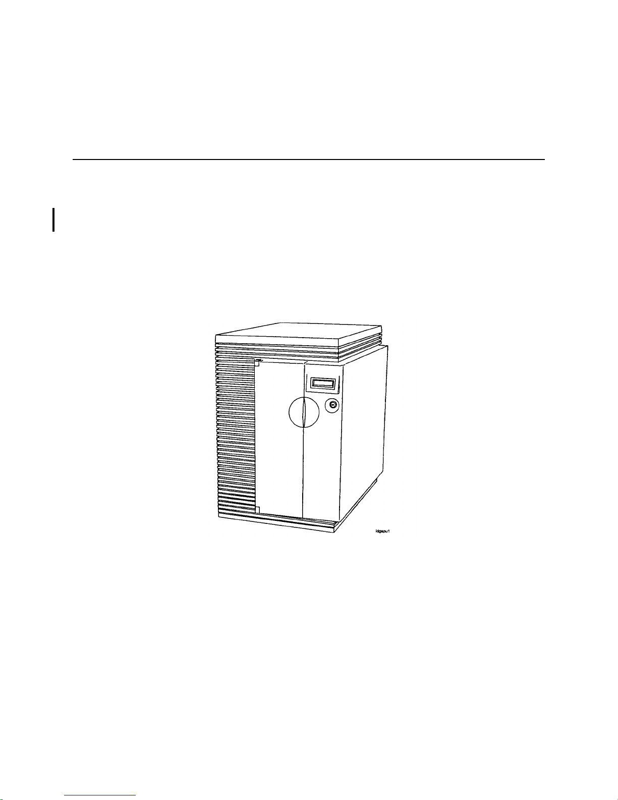
This chapter provides information about the System Processor Unit (SPU) for the HP 3000/9x9KS and
HP9000 K-Class servers, and the HP VISUALIZE K260/K450/K460 EG and XP Workstations. It shows
and identifies the switc hes, displays, bulkhead connector s, and major SPU functional areas.
Figure 1-1 sh ows the fr ont view of a n SPU. The same phys ical cabinet is used for both the HP 3000 a nd HP
9000 SPU.
Figure 1-1. System Processor Unit, Front view
Introduction 1-1
Page 16

HP 3000 Systems
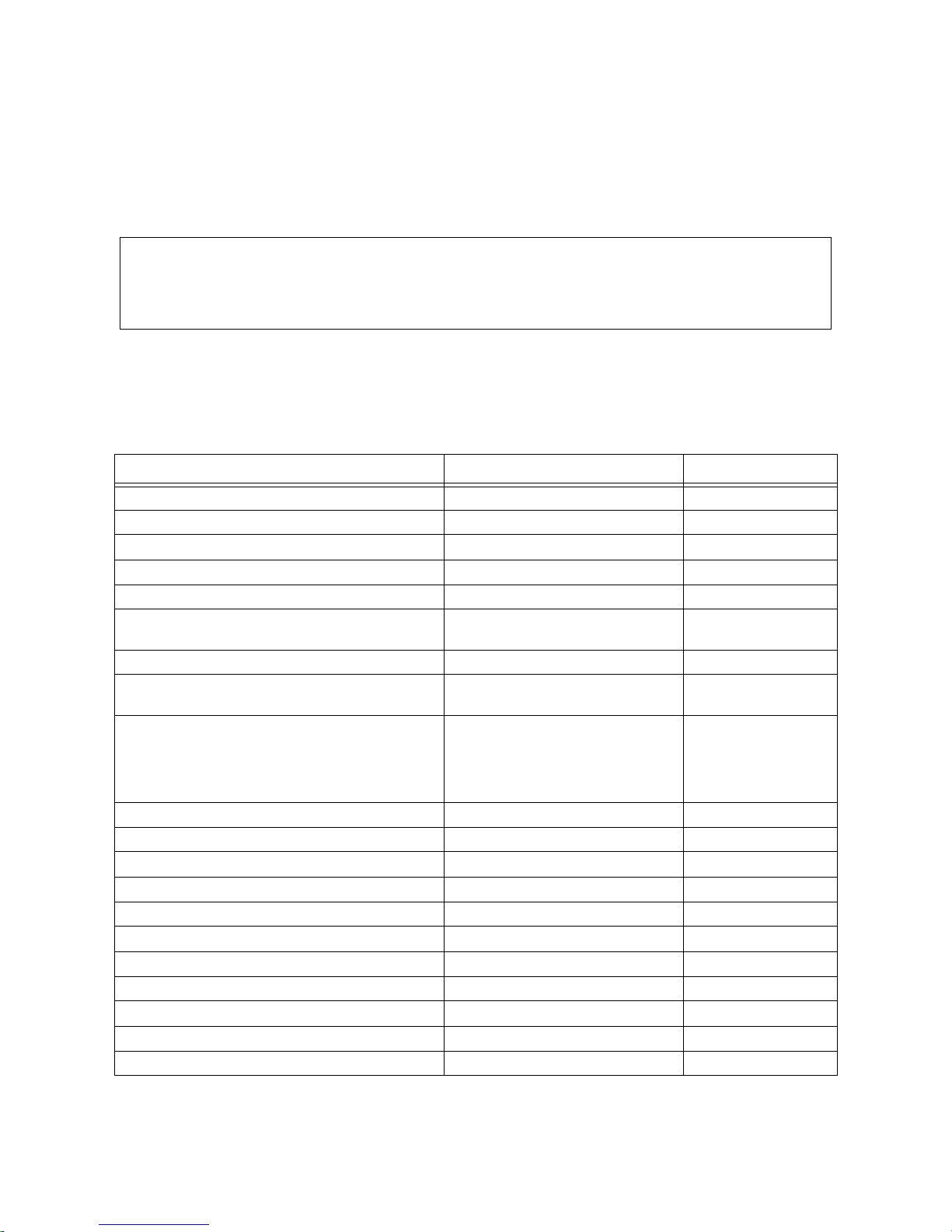
Table 1-1 lists the major componen ts for the HP 3000 Systems.
Table 1-1. HP 3000 System Description
Models 939KS 959KS 969KS/x00 969KS/x20 979KS
CPU PA7200 PA8000
Clock speed
Number of Processors
80MHz
1
100MHz 120MHz 120MHz 180MHz
11 to 4
Supported
Floating Point Coprocessor Integrated
I-Cache 256K 1 MB
D-Cache 256K 1 MB
2
3
HP-PB I/O slots 4
to 8
Main Memory (minimum) 64MB 128MB
Main Memory (Maximum) 3.75GB
O.S. Release 5.0
5
Internal SCSI devices
4
2
(Single-ended)
Internal SCSI devices
4
(Fast-wide)
Internal Modem 1
Internal Audio Card 0
5.5
1.
Clock speed reduced with software.
2.
2 single high slots and 2 double high slots, or 4 single high slots.
3.
Upgradeable to 4 singl e high slots and 4 double high slots, or 8 single high slo ts.
4.
3.75GB maximum m em ory beginning with MPI/iX Release C.55.01.
5.
With patches.
1-2 Introduction
Page 17

HP 9000 Systems
1
Systems
2
8
3
1
.
1
4
1
1
2
8
3
1
4
1
Table 1-2 lists the major componen ts for the HP 9000
Table 1-2. HP 9000 System Description
Models K100 K200 K400 K210 K410 K220 K420
CPU PA7200
Clock Speed 100MHz 120MHz 120MHz
Number of Processors Supported 1 1 to 4
Floating Point Coprocessor Integrated
I-Cache 256K 1MB
D-Cache 256K 1MB
HP-PB I/O slots 4
HP-HSC I/O slots 1
1
4
8
1 3
2
HP-HSC Bus 1 clock speed N/A N/A 32MHz N/A 40MHz N/A 40MHz
HP-HSC Bus 2 clock speed
32MHz
(on Core I/O Card)
Main Memory (Minimum) 32 MB 64 MB 128MB 64 MB 128MB 64 MB 128MB
Main memory (Maximum) 512MB 2GB 3.75GB
Internal SCSI devices
4
2GB
3.75GB
2
4
2GB
3.75GB
(single-ended)
Internal SCSI devices
4
(fast-wide)
Internal Modem 1
O.S. Release 10.0
1.
2 single hig h slots and 2 double high slots, or 4 single hi gh slots.
2.
4 single hig h and 4 double high, or 8 single high.
3.
Add 2 HP-HSC slots or add 4 HP-HSC slots (the Add 2 and Add 4 cannot be combined).
4.
3.75GB maximum memory for 32-bit OS, 4GB maximum memory with 64-bit OS.
4
Introduction 1-3
Page 18

Table 1-2. HP 9000 System Description (continued)
Models K250 K260 K450 K460
CPU PA8000
Clock Speed 160MHz 180MHz 160MHz 180 MHz
Number of Processors Supported 1 to 4
Floating Point Coprocessor Integrated
I-Cache 1MB
D-Cache 1MB
HP-PB I/O slots 4
HP-HSC I/O slots
1
11
HP-HSC Bus 1 clock speed 40 MHz
2
8
3
HP-HSC Bus 2 clock speed (on
32 MHz
Core I/O Card)
Main Memory (Minimum) 128 MB
Main memory (Maximum) 4 GB 8.0 GB
Internal SCSI devices (single-
2
ended)
Internal SCSI devices (fast-wide) 4
Internal Modem 1
Internal Audio Card 0
O.S. Release 10.2
1.
2 single high slots and 2 double high slots, or 4 single high slot s.
2.
4 single high and 4 double high, or 8 singl e high.
3.
Add 2 HP-HSC sl ots or add 4 HP-HSC s lots (the Add 2 and Add 4 cannot be com-
bined).
1-4 Introduction
Page 19

Table 1-2. HP 9000 System Description (continued)
Models K260-EG K460-EG K460-XP
CPU PA8000
Clock Speed 180MHz
Number of Processors Supporte d 1 to 4
Floating Point Coprocessor Integrated
I-Cache 1MB
D-Cache 1MB
HP-PB I/O slots 4
HP-HSC I/O slots
1
1
1
2
8
3
4
2
HP-HSC Bus 1 clock speed 40 MHz
HP-HSC Bus 2 clock speed (on Core I/O Card)
32 MHz
Main Memory (Minimum) 128 MB
Main memory (Maximum) 4 GB 8.0 GB
Internal SCSI devices (si ngle-ended) 2
Internal SCSI devices (fast-wide) 4
Internal Modem 0
Internal Audio Card
6
6
1
O.S. Re lease 10.2
1.
2 single high slots and 2 double high slots, or 4 single high slots.
2.
4 single high and 4 double high, or 8 single high.
3.
Add 2 HP-HSC slots or add 4 HP-HSC slot s (the Add 2 and Add 4 ca nnot be combined).
4.
One additi ona l HSC I/O slot i s ava ilab le on the HP Visua lize 48XP gra phi cs accele ra tor
card bulkhead.
5.
3.75GB maximum memory for a 32-bit OS.
6.
Audio Card on Cor e I/O replaces the Inter nal Modem. If Remote Support is required ,
use an exter nal modem and connect it to the Core I/O card.
5
Introduction 1-5
Page 20
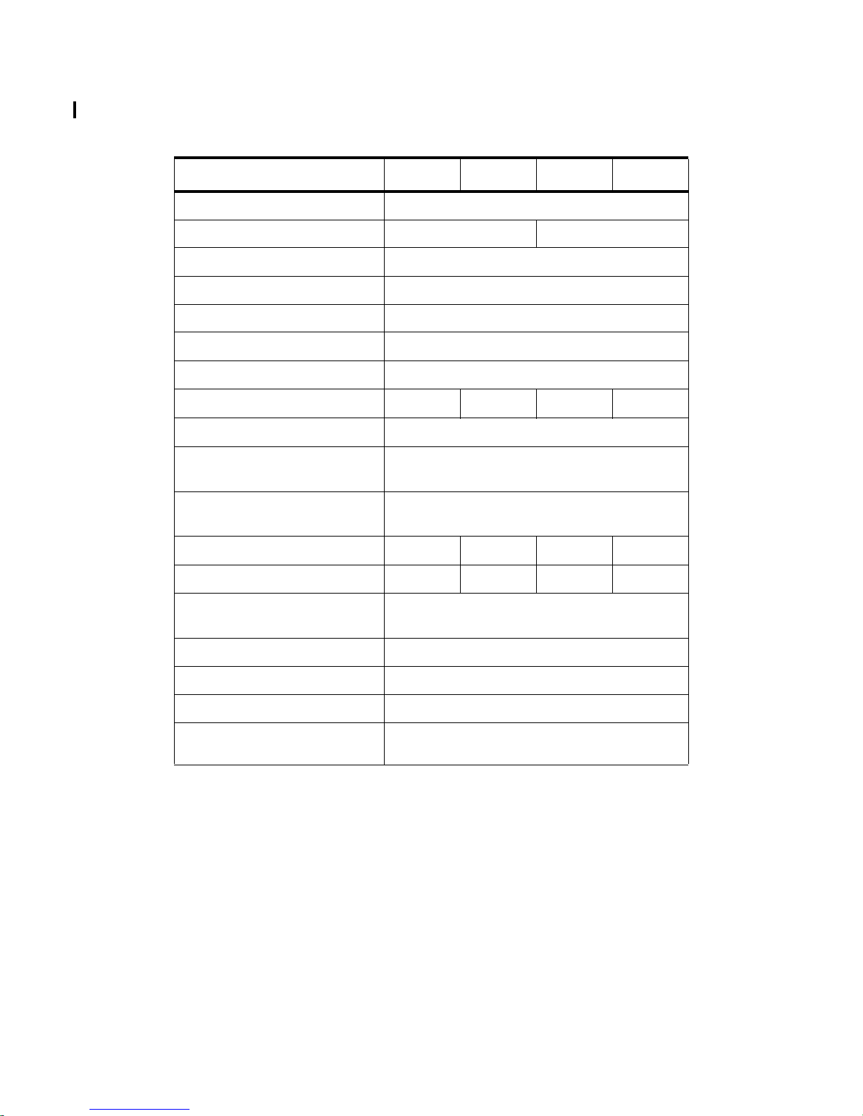
Table 1-2. HP 9000 System Description (continued)
Models K370 K570 K380 K580
CPU PA8200
Clock Speed 200 MHz 240 MHz
Number of Processors Supporte d 1 to 6
Floating Point Coprocessor Integrated
I-Cache 2MB
D-Cache 2MB
HP-PB I/O slots 4
HP-HSC I/O slots
1 to 3 1 to 9 1 to 3 1 to 9
HP-HSC Bus 1 clock speed 40 MHz
HP-HSC Bus 2 clock speed (on
32 MHz
Core I/O Card)
HP-HSC Bus 3/4 clock s pee d (on
Dual Bus 4-Slot HSC Card)
1
40 MHz
Main Memory (Minimum) 128 MB 256 MB 128 MB 256 MB
Main memory (Maximum) 4.0 GB 8.0 GB 4.0GB 8.0GB
Internal SCSI devices (single-
2
ended)
Internal SCSI devices (fast-wide) 4
Internal Modem 1
Internal Audio Card 0
O.S. Release 10.20
with HW extensions
1.
HP9000/K5x0 only
1-6 Introduction
Page 21

2
Hardware Installation and Configuration
This chapter conta ins information on insta lling the computer sys tem as well as hardware conf iguration rules.
The first part of this chapter provides installation summarie s for both the HP 3000 and HP 9000 computer
systems.
The Install summaries are in a pictorial format to provide a brief overview of the installation process. For
more detailed informat ion, refer to the Installation Guides that come with the computer itself .
The Configuration por tion of this chapter refers to the hardware that comp r ises the computer system. This
includes the c onfigura tion rules, a l ocator diagra m, and the har dware addr ess path i nf ormation n ecessa ry to
configure the Operating System software.
To obtain specific configuration information for the Operating System, refer to the HP 3000 or HP 9000
Software configuration Guide, or Administrators Guide for instructions.
Install and Configuration 2-1
Page 22
Installation
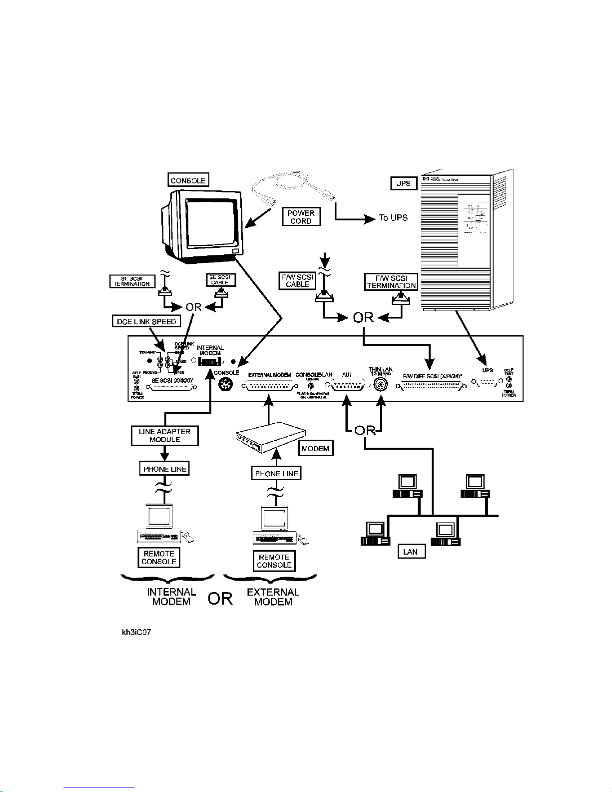
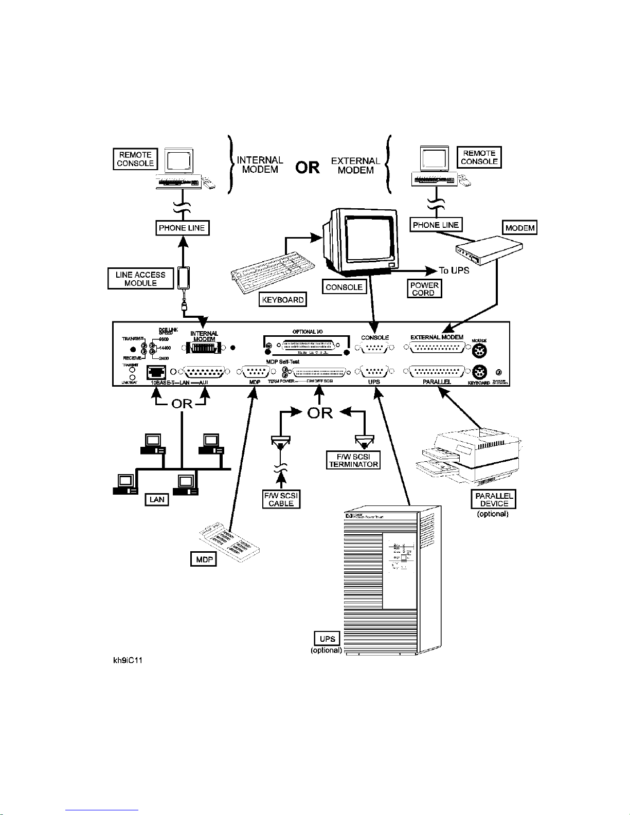
HP 3000/9x9KS Install Summary
Figure 2-1 shows the connect locat ion f or the various components involved in a system installation. For
specific instruc tions on installation, refer to the Installation Guide (HP part number A2375-90005).
Figure 2-1 HP 3000/9x9KS Installation Diagram
2-2 Install and Configuration
Page 23
HP 9000/Kxx0 Install Summary
Figure 2-2 shows the connect locat ion f or the various components involved in a system installation. For
specific instruc tions on installation, refer to the Installation Guide (HP part number A2375-90006).
Figure 2-2 HP 9000/Kx00 Installation Diagram
Install and Configuration 2-3
Page 24
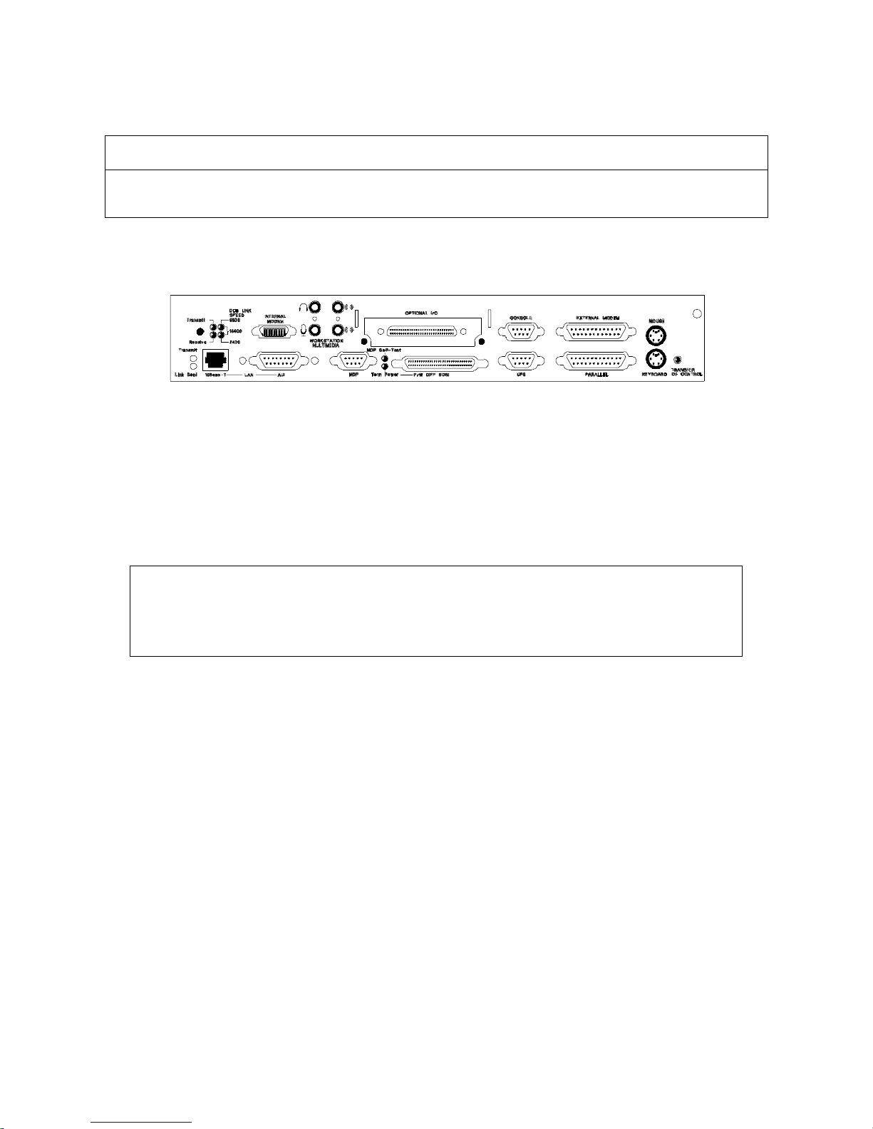
Note
The Core I/O card for the HP9000/K460 workstation features additional jac ks for micr ophone and
headset as shown in the figure below.
System Start-up Process
Once the instal lation is complete (this includes all system peripherals), perform the following steps to turn
on the computer system:
NOTE
Before performing the System Start-up Process, be sure all additional I/O cards and system
upgrades are installe d. Refer to the appropriate configuration rules in this Chapter for the component being added.
1. Turn on all externally conne cted peripherals. Make sure the periphe rals are up with no errors.
2. Turn the computer key switch from STANDBY to ON (or SERVICE if needed).
When the key switch is placed in the ON (or SERVICE) position, the fo llowing sequence of displays are
present on the front panel dis play:
2-4 Install and Configuration
Page 25

Display Panel Environment Observations
Key switch in Standby.
No power cord.
SWITCH OFF Key switch in Standby.
Power cord installed.
PROCEEDING TO
TURN DC ON
OSTAT XXXX Key swit ch is On.
OSTAT XXXX
CPU XXXX
Key switch is On. Di spla y pa nel s hows message, b ack li ght is on 1 to
PDC is lo ading .
Key switch is On.
ISL is running.
Blank Displa y.
AC power installed, back light is off. Fro nt panel
displays SWITCH OFF
2 seconds after display starts.
Ostats and c hassis c odes a re displa ye d at the panel
and console banner. Chassis codes range from
0000 to CDFF. Refer to Chapter 4.
System initialization codes are being displayed.
OS or Diag loading can be star ted. Codes range
from CE00 to CEDF. Refer to Chapter 4.
OSTAT XXXX
CPU XXXXX
RUN FXYF
CPU XXXXXX
Key switch is On.
OS loa d in pr o cess.
Key switch is On.
OS load complete.
OS is ru nn ing.
OS is loading from disk or tape. Codes may range
from CEE0 to CFFF. Refer to Chapter 4. CPU
XXX shows processors installed (0-5).
The OS is finished loading. The X after RUN =
CPU utilization, The Y= number of processors.
CPU XXX shows processors installed (0- 5).
OSTAT in the above sequence can equal one of the following states:
•OFF
• FLT (fault)
• TEST
• INIT (initialize)
• SHUT (shutdown)
• WARN (warning)
•RUN
• ALL
This sequence is followed by the system prompt. Refer to the System Administrators Manuals for the
appropriate operating system instructions to proceed with the system configuration.
Install and Configuration 2-5
Page 26

Configuration Rules
This section contains the configuration rules for the SPU. It includes CPU, Memory, Graphics, HP-HSC,
and HP-PB I/O.
CPU Card Rules
CPU cards must be installed in numerica l order , sta rting with CPU slot 0, then 1, 2, 3, 4, and 5. The
HP 9000/K100 does not ha ve C PU slots. The CPU chip i s moun ted dire ctly on t he syste m board (i nside the
cabinet).
The result of improper installation configuration of the CPU cards will be:
• Console displays a warning message .
• The boot process stops at the PDC prompt.
• Boot command is disabled.
Memory SIMM Rules
Memory for the HP 3000 and HP 9000 syst em are offered in five sizes: 16 MB, 32MB, 64MB, 128MB and
256MB SIMM pairs (32MB, 64MB, 128MB, 256MB, and 512MB increments) . The memory configuration
rules are described in det ai l in Appendix C of this manual.
Graphics Module Rules
If the HP-HSC Expansion card is instal le d, the n all graphic modules must be installed on the HP-HSC
Expansion I/O card.
If the graphic s modules are mixed between the core I/O a nd the expansion I/O, an I/O address overlap will
occur and the following viol ations will be seen:
• Log warning and hex code displays.
• System selftest will halt, stopping the boot process.
If a graphics terminal is used as the system console, refer to the Graphics Terminal Configuration section
for rules and con figuration param eters.
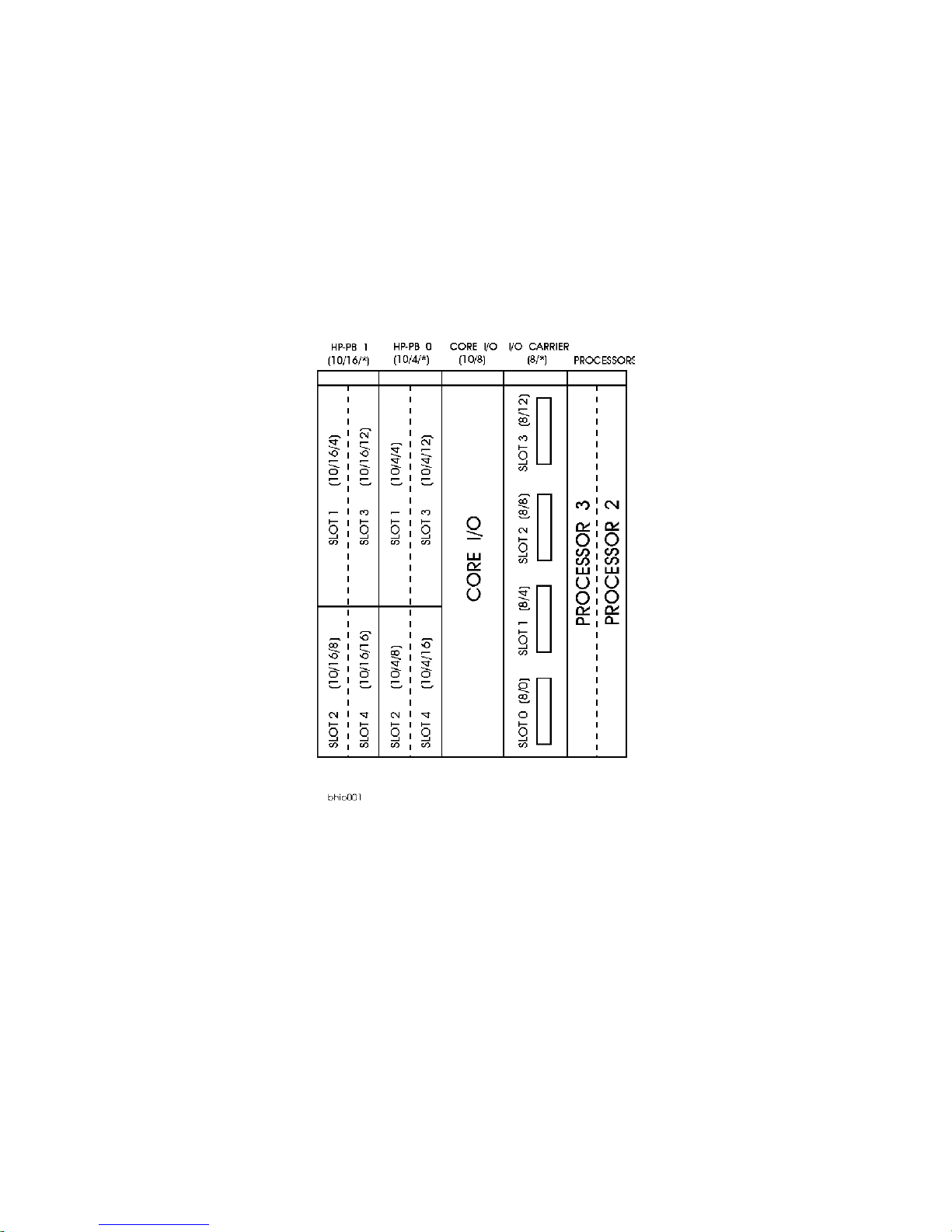
HP-PB Rules
The HP-PB I/O card top row (slots 1 and 3 of HP-PB bus 0 and 1) are setup in two rows of single high card
slots. These slots can accommodate one single high or one double high (but no full high) HP- PB I/O cards.
The single high cards can be install ed in the bottom row (sl ots 2 and 4 of HP-PB bus 0 or 1) and the middle
row (slots 1 and 3 of HP-PB bus 0 or 1). Refer to Figure 2-3 for the K2xx/K4xx I/O slot layout. Refer to
Figure 2-4 for the Kx70/Kx80 layout . The HP 3000/939KS/959KS and HP 9000/K100 only have HP-PB
bus 0. Double high I/O cards can only be installed in slots 1 and 3 of HP-PB bus 0 or HP-PB bus 1.
HPPB paths 10/4/12, 10/4/16, 10/16/12, and 10/16/16 do not exist on Kx70/Kx80 servers. This information must be considered before upgrading to a Kx70/Kx80 server.
Kx70/Kx80 systems have half the slots of K4xx systems, but follow the same HP-PB rules.
2-6 Install and Configuration
Note
Page 27
The configuration rules for HP-PB cards are:
• HP-PB cards are installed in alternating busses
• Double high cards first, followed by the single high cards
• If HP-PB bus 0 and HP -PB bus 1 are use d, al ternate in sta llatio n betwe en the busse s i n the orde r of , Bus
1/slot 1 for the first double high card, then Bus 0/slot 1, continuing until all double high cards are
installed. Then Bus 1/slot 2 for the first single high card, then Bus 0/slot 2, until all single high cards
are installed.
Figure 2-3 HP-PB I/O Slot Location Diagram (K2xx/K4xx)
Install and Configuration 2-7
Page 28
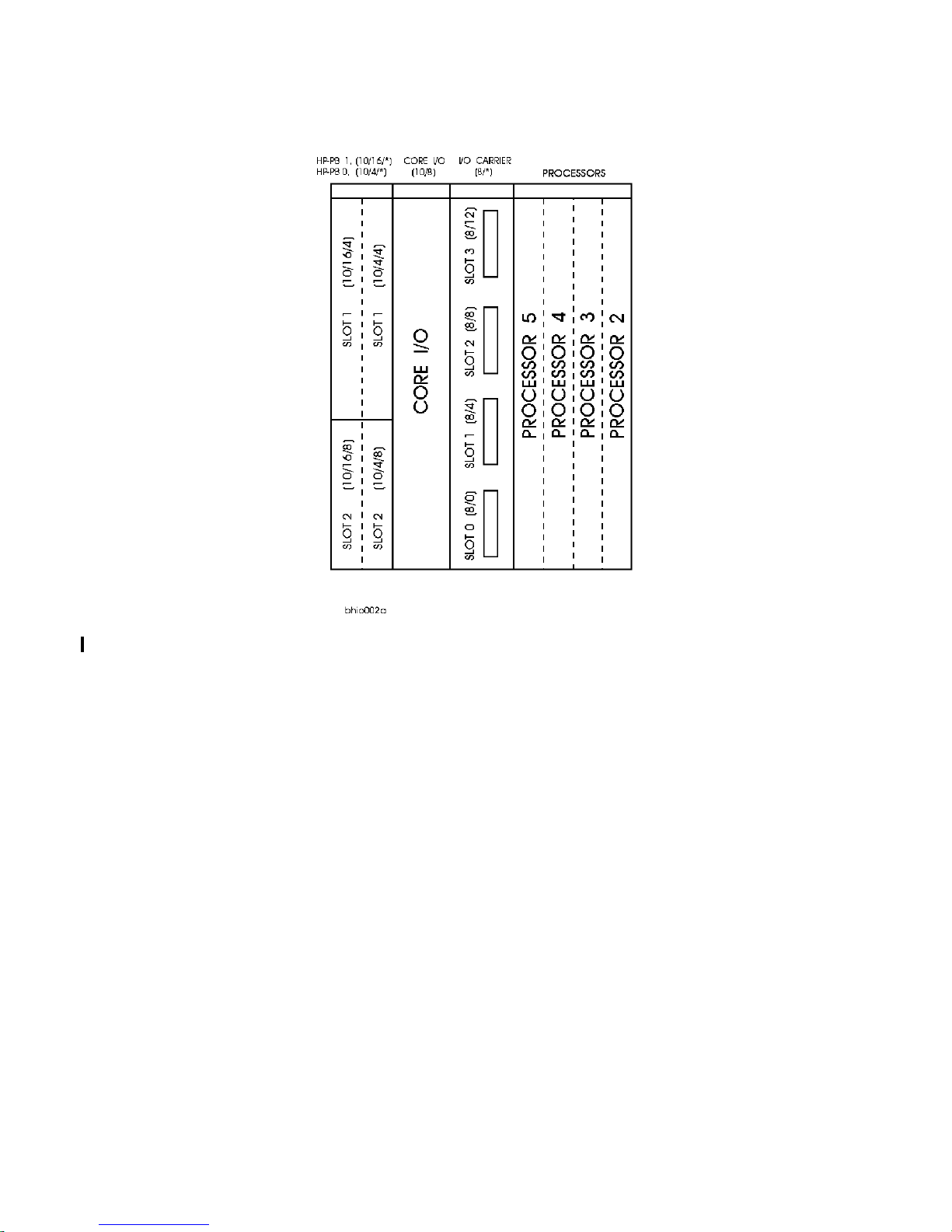
Figure 2-4 HP-PB I/O Slot Location Diagram (Kx70/Kx80)
2-8 Install and Configuration
Page 29
Hardware Configuration
This section provides the System Processor Unit (SPU) hardware conf iguration information. This includes
the address paths, power loa ding and co nfiguration l imits for bot h HP 9000 and HP 3000 SPUs. The a ddress
path inform ation is ne eded to p erform system configuration withi n the operating system software.
NOTE
There are no power loading considerations between the two I/O busses . The power supply in the SPU
is sufficient to accommodate the distribution across all I/O slot locations. The HP-PB Configuration
rules are for performance only.
Address Paths
Tables 2-1, 2-2, and 2-3 list the interna l address paths for the HP computers.
Table 2-1. HP 9000/K100 Path Addressing
Location/Description Device Type Address Path (Dec)
Core I/O card FW DIFF SCSI connector FW DIFF SCSI devices 8/0. (device addr)
Internal Peripheral Bay, slot C (boot dis k) FW SCSI disk drive 8/0.6
Internal Peripheral Bay, slot D FW SCSI disk drive 8/0.5
Internal Peripheral Bay, slot E FW SCSI disk dri ve 8/0. 4
Internal Peripheral Bay, slot F FW SCSI disk drive 8/0.3
Core I/O card console connector (MDP port 0) HP 700/96 system console 8/4/0.0
Core I/O card UPS connector (MDP port 1) 1300VA PowerTrust (UPS) 8/4/0.1
Core I/O card Internal or e xte rnal modem connec-
tor (MDP port 7)
Core I/O card MDP connector: ports 2
3
4
5
6
HP-PB 0, slot 1 HP-PB I/O card 8/4/4. (device addr)
HP-PB 0, slot 2 HP-PB I/O card 8/4/8. (device addr)
HP-PB 0, slot 3 HP-PB I/O card 8/4/12. (device addr)
HP-PB 0, slot 4 HP-PB I/O card 8/4/16. (device addr)
Core I/O card, Optional I/O (HSC) connector Graphics console 8/8.0
Core I/O card, Paralle l connector Supported parallel device 8/12/0
Internal Peripheral Bay, slot A SE SCSI CD-ROM 8/12/5.2
Internal Peripheral Bay, slot B SE SCSI DDS Drive 8/12/5.0
Core I/O card, 10 base or AUI connector Appropriate LAN cable 8/12/6
Core I/O card, Keyboard co nnector graphics option keyboard 8/12/7
Core I/O card, Mouse connector graphics option mouse 8/12/8
HP LAM for Internal modem or an
external modem
A Modem Distribution Panel
(MDP) is connected t o the Core I/O
connector. Supported devices are
then connec ted to the MDP.
8/4/0.7
8/4/0.2
8/4/0.3
8/4/0.4
8/4/0.5
8/4/0.6
Install and Configuration 2-9
Page 30

Table 2-2. HP 9000/K2x0/K4x0 Path Addressing
Location/Description Device Type Address Path
Core I/O card FW DIFF SCSI connector FW DIFF SCSI devices 10/0. (device addr)
Internal Peripheral Bay, sl ot C (boot disk) FW SCSI disk drive 10/0.6
Internal Peripheral Bay, sl ot D FW SCSI disk drive 10/0.5
Internal Peripheral Bay, sl ot E FW SCSI disk drive 10/0.4
Internal Peripheral Bay, sl ot F FW SCSI disk drive 10/0.3
Core I/O card console connector (MDP port 0) HP 700/96 system console 10/4/0.0
Core I/O card UPS connector (MDP port 1) 1300VA PowerTrust (UPS) 10/4/0.1
Core I/O card MDP connector: ports 2
3
4
5
6
Core I/O card Internal or external modem connector (MDP port 7)
A Modem Distribution Pane l
(MDP) is connected t o the Core I/O
connector. Supported devices are
then connected to the MDP.
HP LAM for Internal modem or an
external modem
10/4/0.2
10/4/0.3
10/4/0.4
10/4/0.5
10/4/0.6
10/4/0.7
HP-PB 0, slot 1 HP-PB I/O card 10/4/4. (device addr)
HP-PB 0, slot 2 HP-PB I/O card 10/4/8. (device addr)
HP-PB 0, slot 3 HP-PB I/O card 10/4/12. (device addr)
HP-PB 0, slot 4 HP-PB I/O card 10/4/16. (device addr)
HP-PB 1, slot 1
HP-PB 1, slot 2
HP-PB 1, slot 3
HP-PB 1, slot 4
1
1
1
1
HP-PB I/O card 10/16/4. (device addr)
HP-PB I/O card 10/16/8. (device addr)
HP-PB I/O card 10/16/12. (device addr)
HP-PB I/O card 10/16/16. (device addr)
Core I/O card, Optional I/O (HSC) connector Graphics consol e 10/8
Core I/O card, Parallel connector Supported parallel device 10/12/0
Internal Peripheral Bay, sl ot A SE SCSI CD-ROM 10/12/5.2
Internal Peripheral Bay, sl ot B SE SCSI DDS Drive 10/12/5.0
Core I/O card, 10 base or AUI connector Appropriate LAN cable 10/12/6
Core I/O card, Keyboard connector graphics option keyboard 10/12/7.0
Core I/O card, Mouse connector graphics option mouse 10/12/8.0
HSC I/O Expansion card, slot 0
HSC I/O Expansion card, slot 1
HSC I/O Expansion card, slot 2
HSC I/O Expansion card, slot 3
1.
HP-PB1 slots not available on K2x0.
2.
HSC I/O Expansion slot not available on K2x0.
2
2
2
2
HSC I/O card 8/0. (device addr)
HSC I/O card 8/4. (device addr)
HSC I/O card 8/8. (device addr)
HSC I/O card 8/12. (device addr)
2-10 Install and Configuration
Page 31

Table 2-3. HP9000 Kx70/Kx80 Path Addressing
Location/Description Device Type Address Path
Core I/O card FW DIFF SCSI connector FW DIFF SCSI devices 10/0. (device addr)
Internal Peripheral Bay, sl ot C (boot disk) FW SCSI disk drive 10/0.6
Internal Peripheral Bay, sl ot D FW SCSI disk drive 10/0.5
Internal Peripheral Bay, sl ot E FW SCSI disk drive 10/0.4
Internal Peripheral Bay, sl ot F FW SCSI disk drive 10/0.3
Core I/O card console connector (MDP port 0) HP 700/96 system console 10/4/0.0
Core I/O card UPS connector (MDP port 1) 1300VA PowerTrust (UPS) 10/4/0.1
Core I/O card MDP connector: ports 2
3
4
5
6
Core I/O card Internal or external modem connector (MDP port 7)
A Modem Distribution Pane l
(MDP) is connected t o the Core I/O
connector. Supported devices are
then connected to the MDP.
HP LAM for Internal modem or an
external modem
10/4/0.2
10/4/0.3
10/4/0.4
10/4/0.5
10/4/0.6
10/4/0.7
HP-PB 0, slot 1 HP-PB I/O card 10/4/4. (device addr)
HP-PB 0, slot 2 HP-PB I/O card 10/4/8. (device addr)
HP-PB 1, slot 1 HP-PB I/O card 10/16/4. (device addr)
HP-PB 1, slot 2
HP-PB I/O card 10/16/8. (device addr)
Core I/O card, Optional I/O (HSC) connector Graphics consol e 10/8
Core I/O card, Parallel connector Supported parallel device 10/12/0
Internal Peripheral Bay, sl ot A SE SCSI CD-ROM 10/12/5.2
Internal Peripheral Bay, sl ot B SE SCSI DDS Drive 10/12/5.0
Core I/O card, 10 base or AUI connector Appropriate LAN cable 10/12/6
Core I/O card, Keyboard connector graphics option keyboard 10/12/7.0
Core I/O card, Mouse connector graphics option mouse 10/12/8.0
HSC I/O Expansion card, slot 0 HSC I/O card 8/0. (device addr)
HSC I/O Expansion card, slot 1
HSC I/O Expansion card, slot 2
HSC I/O Expansion card, slot 3
1
1.
HSC Dual Bus 4-slot I/O card, slot 0
HSC Dual Bus 4-slot I/O card, slot 3
HSC Dual Bus 4-slot I/O card, slot 2
HSC Dual Bus 4-slot I/O card, slot 3
1.
HP9000/K5x0 only
1.
1.
1.
1.
HSC I/O card 8/4. (device addr)
HSC I/O card 8/8. (device addr)
HSC I/O card 8/12. (device addr)
HSC I/O car d 12/0. (device add r )
HSC I/O card 12/12. (dev ice addr)
HSC I/O car d 14/8. (device add r )
HSC I/O card 14/12. (dev ice addr)
Install and Configuration 2-11
Page 32

Table 2-4. HP 3000/9x9KS Path Addressing
Locat i on/Descr iption D evice Typ e Addres s Pat h
Core I/O card console connector HP 700/96 system console 10/4/0.0
Core I/O card UPS connector 1300VA PowerTrust (UPS) 10/4/0.3
Cor e I/ O card Inter n al or Exter n a l m odem
connector
HP-PB 0, slot 1 HP-PB I/O card 10/4/4. (device addr)
HP-PB 0, slot 2 HP-PB I/O card 10/4/8. (device addr)
HP-PB 0, slot 3 HP-PB I/O card 10/4/12. (device addr)
HP-PB 0, slot 4 HP-PB I/O card 10/4/16. (device addr)
Core I/O SCSI connector SE SCSI Interface 10/4/20. (device addr)
Internal Periphe ral Bay, slot A SE SCSI CD-ROM 10/4/ 20.2
Internal Peripheral Bay, slot B SE SCSI DDS Drive 10/4/20.0
Core I/O card FW DIFF SCSI connector FW DIFF SCSI Interface 10/4/24
Internal Periphe ral Bay, slot C (boot disk) FW SCSI disk drive 10/4/24.6
Internal Periphe ral Bay, slot D FW SCSI disk drive 10/4/24.5
Internal Periphe ral Bay, slot E FW SCSI disk drive 10/4/25.4
Internal Periphe ral Bay, slot F FW SCSI disk drive 10/4/25.3
Core I/O card, ALS or THINLAN connector Appropriate LAN cable 10/4/0
HP-PB 1, slot 1 HP-PB I/O card 10/16/4. (device addr)
HP-PB 1, slot 2 HP-PB I/O card 10/16/8. (device addr)
HP-PB 1, slot 3 HP-PB I/O card 10/16/12. (device addr)
HP-PB 1, slot 4 HP-PB I/O card 10/16/16. (device addr)
HP LAM for Internal modem or
an Extern al modem
10/4/0.1
Graphics Terminal Configuration
If a graphics t erminal is to be used a s the syst em console you m ust be a ware of the following rules and path
address requirements.
Caution
If you are installin g a graphics te rminal in a system that currently uses a standard RS-232 terminal for
its console, you must reconfi gure the PDC path address for the graphics console before removing the
standard RS-232 console from the syste m.
Supported Graphics Device: The HP A4330A 17" Monitor, the A4331A 20" Monitor, and the A4331B
20" Monitor are the only supported graphics devices at this time. The Monitors will automatically set
themselves to match the graphics device adaptor (A2999A or A3519A). The graphics device adaptor has
the following characte ristics:
Resolution = 1280 x 1024
Scan Rate = 75Hz
2-12 Install and Configuration
Page 33

Installation:
1. The graphics device adaptor (A2999A or A3519A) card should be installed in the Core I/O card,
Optional I/O slot, when no HP-HSC Expansion I/O card is present. If the 2 or 4-slot HP-HSC
Expansion I/O card is present, the n the graphics device adaptor must be installed in the Expansion
I/O card . This is to avoid address overla p problems when graphics device adaptors are installed in
both the Core I/O and Expansion I/O cards.
Note
The Dual Bus 4-Slot HSC Expansion I/O card does not support graphics cards.
The HP VISUALIZE 48 3D Graphics will occupy the slot normally used by the HSC I/O card.
2. Use the graphics monitor cable that comes with the graphics monitor to connect between the graphics
card and graphics monitor.
3. Connect the graphics keyboard to the Core I/O card connector marked
KEYBOARD.
4. Connect the graphics mouse to the Core I/O connector marked MOUSE.
The Keyboard path address is 10/12/7.0 a nd the Mouse path address is 10/12/8.0. These address paths are
set and cannot be changed, they corre spond to the connectors on the core I/O card.
Since the graphics monitor connects to a graphics device adaptor card that can be in different slots, its
address path must be configure d in PDC to reflec t its slot location. You must change the Console Path
Address in PDC to either 10/8.0 (for the core I/O Optional I/ O slot), or one of the following path addresses
for the HP-HSC Expansion I/O card slots:
Core I/O, Optional I/O slot 10/8.0
HP-HSC I/O Expansion card, slo t 0 8/0.0
HP-HSC I/O Expansion card, slo t 1 8/4.0
HP-HSC I/O Expansion card, slo t 2 8/8.0
HP-HSC I/O Expansion card, slo t 3 8/12.0
Install and Configuration 2-13
Page 34

Internal Modem Configuration
The internal modem is c onfigure d with t he on-line diagnosti c utilit y moduti l. Moduti l can only be run f rom
the Diagnostic Users Int erf ace (DUI). Modutil provides three functions:
1. Mode m Terminal Interf ace
2. Modem Diagnostics
3. Modem Configuration Information
Note that the internal modem is not present in HP VISUALIZE workstation models.
Modem
Terminal Interface provides the terminal interface between the modem and the user. It takes AT
commands from the keyboard and sends them to the modem. Refer to Table 2-4 for the list and description
of the HP AT commands. It also receives data from the modem and displays it on the terminal.
The Modem Diagnostics provide the following diagnostics:
• Port Configuratio n Diags - Communicate with the modem by auto-selected combinations of port
configurations (baud rates, character bits, etc.)
• Modem Selftest I - Performs the modem automatic selftest.
• Modem Selftest II - Performs the modem local analog loopback test.
• Modem Sel ftes t III - Performs the mode m loc al digital loopback test.
• Modem Selftest IV - Performs the modem remote digital loopback test.
• Combined Modem Selftest - Performs modem selfte sts I, II and III.
The Modem Configuration Information mode gives displays of the operating parameters, configuration
parameters, and S register values.
To configure the interna l modem perfor m the following steps:
Note
ONLINE diagnostics need to be loaded prior to performing the fol lowing steps and configur ing the
internal modem.
1. At the system prompt enter the sysdiag command. The DUI prompt should appear.
2. At the DUI prompt enter modutil command.
3. At the modutil prompt (MU>) enter terminal to go into the terminal command mode. The following
terminal start message should be displayed:
The modem is on port 7 of the Core I/O board
Baud rate is 19200 bps, character size is 8 bits
Do you want to make any changes? Yes/No __
Baud rate (19200 bps) refers to the serial baud rate, not the modem bps on-line rate. If Y (yes) is entered
you can change the baud rate a nd cha racter s ize. The program the n repeats th e t erminal mode st art mes sage
with the new setup parameters.
If N (no) is entered , to acce pt the displayed parameters, the program displays the following message:
You can now enter modem commands or use Ctrl+X to return to the MU prompt
2-14 Install and Configuration
Page 35

The AT commands can now be entered to further configure the internal modem.
In the HP AT command set descriptions, *** (three asterisks) indicate Default Setting.
Table 2-5. HP AT Command Set
Command Values Description
AT Attention code that prece des most command lines.
RETURN P re ssi n g R et u rn ex ecutes mo st co mmands.
A Answer call, even if no ring present.
A/ Repeat last command. Do not pr ec ede this command with AT. Do not
press Return to execute.
A: Continuous re dial (10 r edial s in DOC un its) of last numbe r un til a nswere d.
(Used only in the U.S.A.)
$An n = 0 or 1 *** $A0 discards dat a during auto-reliable time period.
$A1 buffers data during auto-reliable time period.
#An n = 0 to 3 *** #A0 means 14,400 to 12,000 to 9600 to 4800 to 2400 to 1200 to 300
bps, on-line.
#A1 means 14,400 bps, on-line, only.
#A2 means 14,400 to 9600 to 4800 bps, on-line, only.
#A3 means 2400 to 1200 to 300 bps, on-line, only.
&Bn n = 0 or 1 *** &B0 means normal transmit buffer size.
&B1 means redu ce d transmi t buffe r size .
&BSn n = 0 or 1 &BS0 means maximum transmit block size of 64 characters.
***&BS1 means maximum trans mi t block size of 256 characte rs.
$BAn n = 0 or 1 ***$BA0 means Baud Adjust is off, speed co nversion is on.
$BA1 means Baud Adjust is on, speed conversion is off.
&Cn n = 0 to 2 &C0 forces Carrier Detect on.
***&C1 lets Carrier Detect act normally.
&C2 lets Carrier Detec t drop S24 time on disconnect.
Ds s = phone# Dial a telephone number (s), where s may include up to 60 digits or T, P,
R, comma an d ; characters.
&Dn n = 0 to 3 &D0 DTR is ignored.
&D1 means modem r e turns to command state.
&D2 lets modem react to DTR normal ly.
***&D3 causes modem to reset to modem default parameters.
En n = 0 or 1 E0 means do not echo Command Mode characters.
***E1 means do echo Command Mode characters.
Install and Configuration 2-15
Page 36

Table 2-5. HP AT Command Set
Command Values Description
&En n = 0 to 15 &E0 means V.42 normal mode.
***&E1 means V.42 auto-redial mode.
&E2 means V.42 reliable mode.
&E3 means no modem-initiated flow control.
&E4 means CTS modem-initiated flow control.
***&E5 means Xon/Xoff modem-initiated flow control.
***&E6 means Xon/Xoff not passed through.
&E7 means Xon/Xoff passed through.
***&E8 means Enq/Ack pacing off.
&E9 means Enq/Ack pacing on.
&E10 means normal mode flow control off.
***&E11 means normal mode flow control on.
&E12 means pacing off.
***&E13 means pacing on.
&E14 not used.
&E15 not used.
$EBn n = 0 or 1 ***$EB0 enables 10 bit mode.
$EB1 enables 11 bit mode.
%En n = 0 to 3 %E0 means modem will not es cape.
***%E1 means +++ method.
%E2 means break method.
%E3 means either +++ or break methods.
#Fn n = 0 to 2 #F0 means no fallback when on-line.
#F1 means fallback from 14400 to 4800 bps when on-l ine.
***#F2 means fallback to 4800 bps from 14400 bps/fall forward if
line improves.
&F &F loa ds factory default values from ROM.
$Fn n = 0 or 1 $F0 means do not fa llback to normal connect if CR rec eived.
***$F1 means fallback to norm al connect if CR received.
&Gn
(Not applicable
in the U.K)
n = 0 to 2 ***&G0 turns off CCITT guard tones. (exc ept for Italy and New Zea land)
&G1 turns on CCITT 550 Hz guard tone.
&G2 turns on CCITT 1800 Hz guard tone. (default for Italy and New
Zealand)
Hn
(Not applicable
n = 0 or 1 H0 means hang up (go on hook).
H1 means go off hook.
in France)
In n = 0 to 2 I0 requests modem ID#.
I1 requests firmware revision #.
I2 for MTS internal use.
L5 L5 lists all current ope rating parameters .
L6 L6 lists all current S-registers values.
L7 L7 lists additional parameters.
#Ln n = 0 to 3 ***#L0 means modems negotiate V.42 mode.
#L1 means MNP on and LAP-M off.
#L2 means LAP-M on and MNP off.
#L3 means no detection phase but go directly to LAP-M.
2-16 Install and Configuration
Page 37

Table 2-5. HP AT Command Set
Command Values Description
Mn n = 0 to 3 M0 means monitor speaker always off.
***M1 means monitor on until ca rrier detected.
M2 mean s mo ni t or al w ay s o n.
M3 means monitor on during dialing, off during handshaking.
$MBn n = speeds $MB75 selects CCITT V.23 mode.
$MB300 selects 300 bps on-line.
$MB1200 selects 1200 bps on-line.
$MB2400 selects 2400 bps on-line.
$MB4800 selects 4800 bps on-line.
$MB9600 selects 9600 bps on-line.
***$MB14400 selects 14400 bps on-line.
O Exit command mode and go into on-line mode.
P (not appl icable
***Modem will pulse dia l num bers following the P.
in Denmark)
&Pn
(Not applicable
n = 0 or 1 ***&P0 means 60-40 pul se ratio.
&P1 means 67-33 pulse rati o.
in the U.K.)
Qn n = 0 to 2 ***Q0 means result codes s ent.
Q1 means result cod es will be suppr e sse d (quiet ).
Q2 means dumb answer mode.
&Qn n = 0 or 1 ***&Q0 selects Multi-Tech command set.
&Q1 selects AT command set.
Rn n = 0 to 2 ***R0 means modem will not reverse modes.
R1 means mo dem wi ll reverse modes.
&Rn n = 0 to 2 ***&R0 lets clear to send act normally.
&R1 forces clear to send on.
&R2 drops 2 seconds on disconne ct
$Rn n = 0 or 1 $R0 means disconnect after 12 retransmits.
$R1 means do not disconnect after 12 re transmits.
&RFn n = 0 or 1 &RF0 selects CTS follows RTS
***&RF1 selects CTS to act independently.
Sr=n r = 0 to 16, 18, 24,
and 25
Sr? r = 0 to 16, 18, 24,
Sets value of register r to value n. n is entered in decimal format (n
varies).
Reads value of register r and displays value in 3-digit deci mal form.
and 25
$SBn n = speeds $SB300 selects 300 bps at serial port.
$SB1200 selects 1200 bps at serial port.
$SB2400 selects 2400 bps at serial port.
$SB4800 selects 4800 bps at serial port.
$SB9600 selects 9600 bps at serial port.
***$SB19200 selects 19200 bps at serial port.
&SFn n = 0 or 1 ***&SF0 selects DSR follows CD.
&SF1 selects DSR independent.
Install and Configuration 2-17
Page 38

Table 2-5. HP AT Command Set
Command Values Description
&Sn n = 0 to 2 &S0 forces data set ready on.
***&S1 lets data set ready act normally.
&S2 data set ready drop is regulated by S24 on disconnect.
T Modem will tone-dial numbers following the T.
&Tn n = 4 or 5 &T4 means enable response to request for remote digit al loopback.
***&T5 means disable response to request for remote digital loopback.
#Tn n = 0 or 1 #T0 turns off trellis coded modulation.
***#T1 turns on trellis coded modulation.
Un n = 0 to 3 U0 places modem in analog loop originate mode.
U1 places modem in analog loop answer mode.
U2 means remote digital loopback.
U3 means local digital loopback.
Vn n = 0 or 1 V0 means result codes sent as dig its (terse mode).
***V1 means result codes sent as words (ver bose mode).
W Wait for new dial tone.
Xn
(Default varies
by country.)
n = 0 to 4 X0 selects basic Result c odes (w/o connect 1200, connect 2400).
X1 selects extend result codes (w/connect 1200, connect 2400).
X2 selects standard AT command set with no dial tone.
X3 selects standard AT command set with busy.
X4 selects standar d AT command set with no dial tone and busy.
Yn n = 0 or 1 ***Y0 disables sendin g or responding to long space break.
Y1 enables sending or resp onding to long space breaks .
Z All configurations are reset to default va lues.
, in dial command Causes pause during dia ling. (In Sweden, not to be us ed in place of W
command.)
; in dial command Causes return to command mode after dialing.
! in dial command Causes mode m to flash on-hook. (Not appl icabl e wi th pul se di al in Aus tria
and Germany. Not applicable in the U.K.)
@ in dial command Causes modem to wait for ringback, then 5 seconds of silence before
processing next part of command.
+++AT<CR> Escape code. Brings modem into command mode while still
remaining on-line. Enter +++ followed by the letters
A and T, up to ten command characters, and a Return.
2-18 Install and Configuration
Page 39

Table 2-6. S-Register Definitions
Register Unit Range Description
S0 1 ring 0-255 Sets number of rings until modem answers.
S1 1 ring 0 - 255 Counts rings which have occurr ed.
S2 ASCII 0-127 Sets escape code character.
S3 ASCII 0-127 Sets character recognize d as RETURN.
S4 ASCII 0-127 Sets character recognized as LINE FEED.
S5 ASCII 0-127 Sets character recognize d as BACKSPAC E.
S6 1 second 2-255 Determines wait time for dial tone.
S7 1 second 1-255 Determines how long modem will wait for carrier before aborting
the call .
S8 1 second 0-255 2 sets pause time caused by a comma character in a dial command.
S9 100 mSec 1-255 Sets carrier detect respon se time.
S10 1 00 mSec 1-255 Sets delay time betwee n when ca rrier is lost and when modem
disconnects.
S11 1 mSec 1-255 Sets time duration of and spacing between tones in tone-dialing.
S13 ASCII 0-127 Determines remote configuration escape character.
S17 10 mSec 0-2.5 Determines length of break time in seconds (space) to PC.
S24 50 mSec 0-255 Sets DSR/CTS/CD dropout time.
S25 100 mSec 0-255 Sets DTR dropout time.
S26 1 0-255 Specifies allowed failed attempts.
S30 minutes 0-255 Inactivity timer used to disconnect modem.
S32 1 00 mSec 0-255 Set duration in which modem will wait for a <RETURN> to be
entered durin g es cape sequence executi on.
S34 ASCII 0-60 Buffer length of command mode after on-line escape sequence.
Table 2-7 . M odem Result Co de s
Digit Words Eff e ct
0 OK Command was executed without error, ready for next command.
1 CONNECT Modem has detected carrier and gone on-line.
2 RING Modem has detected ring caused by incoming call.
3 NO CARRIER No carrier signal has been detected within the allowed time.
4 EEROR Error in command line (to o many, or invalid characters).
5 CONNECT 1200 Modem has detected carrier at 1200 bps and gone on-line.
6 NO DIAL TONE N o dial tone has been detected.
7 BUSY A busy signal has been detected.
8 NO ANSWER Remote system did not answer.
9 CONNECT 2400 Modem has detected carrier at 2400 bps and gone on-line.
11 CONNECT 4800 Modem has detected carrier at 4800 bps and gone on-line.
12 CONNECT 9600 Modem has detected carrier at 9600 bps and gone on-line.
13 CONNECT 14400 Modem has detected ca rrier at 14400 bps and gone on-li ne.
Install and Configuration 2-19
Page 40

Internal Modem Remote Access
This section provides the infor mation on enabling or disabling the remote access through the internal
modem. The process to allow or not allow r emote access i s different between the HP 9000 systems and the
HP 3000 systems.
NOTE
The following procedures are only applicable if HP Predictive has not been installed. If HP predictive is installed, use Predi ctive to configure the internal modem for remote access. Refer to the Pre-
dictive Support User’s Guide (part number 50779-90018).
The HP 50759A/B modem can not be used for dialin purposes due to an incompatibility of flow
control parameters.
HP-UX Remote Access
The process for the HP-UX HP 9000 systems is provided through a script called dialin. The syntax for
running the dialin script is:
>dialin [-bbaud] action
Where:
dialin - is the HP-UX script.
[-baud] - can be used to specify a baudrate (do not change the default baud rate).
action - is one of three choices : enable, disable, or status.
Example of enable remote access:
>
dialin enable (this enables remote access and uses the default baudrate)
or
>dialin status (this displays the current status, either disabled or enabled)
CAUTION
Do not use a baud rate other than the defau lt of 19200 KBS. Other baud rates could cause the
dialin process to malfunc tion
The system then displays messages sim ila r to the following:
Created device: /dev/cul0p7
Created device: /dev/ttyd0p7
Created device: /dev/cua0p7
Dialin enabled
To disable remote ac cess, use the disab le action with the dialin command. The stat us action wil l display the
current state of either enabled or disabled for remote access.
2-20 Install and Configuration
Page 41

MPE/iX Remote Access
NOTE
The following procedur es are only applicabl e i f HP Predictive has not been installed. If HP predictive is installed, use Predi ctive to configure the internal modem for remote access. Refer to the Pre-
dictive Support User’s Guide (part number 50779-90018).
To have remote access for the HP 3000 computer you must configure Logical Device 21 in the operating
system and on the core I/O card.
Logical Device 21 System Configuration
To establish a dial-in ses sion for remote access thr ou gh the inte rnal mo dem, logical device 21 has to be
configured in the operat ing system. To check the logical device 21, perform the following steps:
1. At the
2. At the
3. AT the
MPE/iX prompt, type
SYSGEN> prompt, type
IO> prompt, type
SYSGEN
lpath 10/4/0.1
.
IO
. This puts you into the I/O submenu of SYSGEN.
. The lpath (l ist pat h) command will display the configur ed
parameters for path address 10/4/0.1, as shown:
PATH: 10/4/0.1 LDEV: 21
ID: A2372-60003-CONSOLE-TERMINAL TYPE: TERM
PMGR: CDM_CONSOLE_DM PMGRPRI: 9
LMGR: TIO_TLDM MAXIOS: 0
4. If the information is incorrect, delete device 21 by typing
io> DD 21
, before adding the corr ect
information.
5. If there is no information displayed for the path 10/4/0.1 (logical device 21), then add the necessary
configuratio n information with the AD 21 command, as shown:
io> AD 21 ID=A2372-60003-CONSOLE-TERMINAL; PATH=10/4/0.1
6. In the I/O submenu of SYSGEN, do a list device 21 (LD 21) and ensure that the following
information is shown:
LDEV: 21 DEVNAME: OUTDEV: 21 MODE: JAID
ID: A2372-60003-CONSOLE-TERMINAL RSIZE: 40 DEVTYPE: TERM
PATH: 10/4/0.1 MPETYPE: 16 MPESUBTYPE: 0
CLASS: TERM
Install and Configuration 2-21
Page 42

Core I/O Remote Console Port Configuration
The internal modem port on the core I/O card must also be configured as Logical Device 21. This is done
NMMGR from MANAGER.SYS. The following procedure needs to be done one time.
in
1. Run NMMGR from MANGER.SYS.
2. The first screen is the
Open Configurati on/Directory File Screen.
3. Press the [F1] (open config) key to reach the main screen.
4. Press the [F1] (DTS) key to reach the Host Configuration screen.
5. Press [F4] (
Go To UserPort) key to reach the HP Support Modem Port screen.
6. Modify the screen fields as shown below:
Logical Device: 21
Line Speed: 9600
Modem: 1 [US Modem]
Parity: None
7. Press [F6] (Save Data) to save the configuration data.
8. Press the [
9. Type
Home] key to position the cursor on the command line at the top of the screen.
VALIDATE
and press [Ent er]
10. Press [F2] (Validate DTS/LINK). Validating the DTS/LINK also cross validates NMCONFIG with
SYSGEN.
11. Exit
NMMGR by returning through the previous screens, or type EXIT at the command line.
Anytime a change is made to the system configuration in SYSGEN, it is necessary to reboot the system in
order for the chang e s to tak e effe ct .
Enabling or Disabling Remote Access Hardware
Once the internal modem is configured for remote access, the computer needs to be enabled, or disabled.
Also at this point, you can select either the internal or external mode. An internal or external modem can
be used for dialout/dia lin on an HP computer system. Howe ver, only one of these modems can be used at a
time. The line speed between the inte rnal modem and the system defaults to 19,200 bits/sec and is not
configurable. The line speed for the external m odem can be configured at 19200, 9600, 2400, or 1200 bits/
sec. To enable, disable , or selec t which modem to use for the remote access, perform the following steps:
1. Put the key switch in the SERVICE mode.
2. At the system console, press
[CTRL]+B. This puts you into the command mode.
2-22 Install and Configuration
Page 43

3. Check to see if the remote console is locked, if so, unlock it with the Unlock Remote (UR) comman d,
before configuring a ccess or enabling remote console.
4. When dialing in for remote console access, there is no speed sensing, so it is necessary to verify that
the remote console port is conf igur ed for the same speed as the originating modem. To configure the
remote console port for the appropriate speed, use the Configure Access (
CA) command mode. The
following information is displayed:
CM> CA
Current remote support modem port configuration:
Modem: Internal modem
Internal modem autoanswer: On
Bit R a te :
Protocol:
System identification:
Do you wish to change the configurati on? (Y/ N ):
2400 (bits/sec)
Bell
5. If the port configuration needs to be changed, type
6. To enable the remote console enter the Enable Remote (
Y and enter the appropriate information.
ER) comman d at the CM> prompt.
7. To disable the remote console enter the Disable Remote (DR) command at the CM> prompt.
8. When finished, exit the PDC command mode and put the key switch back into the ON position.
Install and Configuration 2-23
Page 44

2-24 Install and Configuration
Page 45

3
Troubleshooting
Introduction
This chapter presents the overall strategy for troubleshooting failures on the HP 3000/9x9KS, HP 9000/
Kxx0 Class systems and HP VISUALIZE Kx50-EG, Kx60-EG, and Kx60-XP workstations, and provides
some procedures you can follow that will help you isolate most system problems.
The chapter is organized so that you can diagnose failures in a logical manner from the "top down",
regardless of your exper ie nce. You can use the information and procedures in this chap ter to isolate and
correct nearly all syste m hardware failures.
If a problem occurs that is not covered here, you should consult more experienced support personnel
within your organization or contact the nearest Hewlett-Packard Response Center for assistance. Care
should be taken before takin g any steps to remedy a failure. Always collect as much information as poss ible about the failure.
Never swap out a Field Replaceable Unit (FRU) until you ha ve ascertained the following:
• The failure symptoms
• All status indicators
• All console and front panel messages
• System configuration
• Number of users logged on
• Application or tasks running at the time of the failure
• All other informatio n that may help describe the failure
Use this information, along with the procedures in this chapter, to aid in selecting appropriate corrective
action. Keep a log of all actions you take for future reference.
Troubleshooting 3-1
Page 46

Calling the Response Center
If your problem is ser ious enough to cal l the HP Respon se Center, gat her the f ollowing inf ormation to gi ve
to the Response Center engineer who will be calling back:
1. The modem telephone number and Baud rate.
2. History and nature of the probl em:
A. When did the problem first occur?
B. What changes have occurred on the system?
C. Has the proble m ever occurred befo re?
D. Can the problem be reproduced?
E. Is the problem intermittent?
3. All troubleshooti ng information gathered so far. For example:
A. Record the system panic message displayed on the console.
B. If an HPMC is displayed, record the console hex display code.
C. If the system did not reboot, record the sequence of 4-digit codes at bottom of console display.
(Press Control-B first.)
4. Call the Response Center. If you are certain the problem is hardware, ask for "Hardware Assistance."
5. Use your judgment about whether to reboo t at this point and allow users to log back on, without
waiting for the Response Cente r engineer to call back. For example, if an HP-UX computer does not
execute savecore, you may want to talk wit h the Response Center before rebooting.
If you choose to wait for the Response Center engineer to call back before allowing users back on, please
note this fact to the Response Center Coordinator so that your call is appropriat ely prioritized.
3-2 Troubleshooting
Page 47

Safety Considerations
Follow the procedures lis ted belo w to ensure safe hand ling of compone nts and to prevent ha rm to both you
and the server:
• Use an anti-static wrist str ap and a grounding mat, such as those included in the Electric a lly
Conductive Field Service Kit.
• Handle PCAs and components by the edges only. Do not touch any metal-edge connectors or any
electrical com p o nen ts.
The keyswitch does NOT have an OFF position. There is a STANDBY position in which all but Three
FRUs are turned off. The three FRUs which are still ON and should not be removed or installed with
power applied are the POWER SUPPLY, POWER MONITOR, AND THE LC DISPLAY. Install and
deinstall the Power Supply, Power Monitor, and the LC Display as follows:
1. Unplug the system.
2. Wait 10 seconds.
3. Proceed To Deinstall/install FRU.
Hard Failures
Hard failures are solid failures. They usually occur during power on, selftest and system initialization, and
they may halt the system. The steps to take when troub leshooting a hard failure are:
1. Obtain front panel display status. Also note any system console messages.
2. Find the chassis code in Table 3-7., hardware troubleshooting. Note the cause and follow the steps
listed in the action column .
In some cases, failure messages r elated to the power system are displayed. Refer to the Power System
messages Tables 3-1 through 3-5 for cause an d action for each message.
Troubleshooting 3-3
Page 48

Power System Troubleshooting
Table 3-1 provides some initia l powe r-on type troubleshooting suggestions. For other power system
problems, refer t o the more d etai le d descriptions and procedures in this section.
Table 3-1. Power-On Troubleshooting
SYMPTOM ACTION
No front panel message
displayed and no sy stem operatio n .
1. If P ower Trust is ins talled
a. Check that the power out put cable is connected f r om th e PowerT rust (UPS)
output recept ac le to the system AC input recept acle.
b. Check that the AC power cord from the UPS is plugged into the AC power
source receptacl e.
c. Check that the UPS output switch is in the ON position.
d. The UPS AC Output indicator should be green (AC power is being supplied).
e. Disconnect the power cable from the system AC input receptacle. Dis connect the
AC power cord from the UPS, connec t it to t he sys tem AC input recept acle , and th en
plug it into the AC power source.
f. If there is a display on the panel, replace the UPS. Otherwise, continue to Step 2.
2. Check for AC power at the power source. Plug another device into the
receptacle. Check the circuit breaker or breaker panel. Reset the circuit breaker
if necessary.
3. If AC power is present and no display
a. Replace Power Monitor PCA.
b. Replace Power Supply.
c. Check internal cables, Power Monitor to front Panel.
No front panel display
and the system is operating
3-4 Troubleshooting
d. Replac e the s y st em boa r d
1. If the operating system is running with no problems.
a. Shutdown the operating system.
b. Check internal cables, power monitor to front panel.
c. Replace the front panel.
d. Replac e th e p ower monito r car d .
e. Replace the system system board.
Page 49

The power system consists of a Power Supply and a Power Monitor card. The foll owing is a basic block
diagram of the power system:
Figure 3-1. Power System Diagram
As shown on the block diagram, the Power Monitor card interfaces to the System Board, Core I/O card,
Display Panel, key switch, a nd the syst em fans. The Power Supply and the Power Monitor cards connect
to the System Board. The System Board acts as a backplane for distributing DC voltages to all PCAs that
are installed in the system.
Power Supply
The Power Supply is a 1250VA auto-ranging supply (1700VA for HP9000 models Kx50/K260/K460/
Kx70/Kx80, HP VISUALIZE workstations, and the HP3000 979KS). There are no test points or
adjustments on the Power Supply. To fully remove power from the system, AC power must be removed.
The Power Supply does not have a circuit breaker. Whenever AC is connected, the Power Supply
continuously pr ovides +15V House Keep ing Power (HKP) t o th e Power Monitor car d. The Power Monitor
card is active even when the Key switch is in the Standby position.
Troubleshooting 3-5
Page 50

Table 3-2 shows the DC voltage requirements for the individual components of the compute r.
Table 3-2. DC Voltage Requirements
Computer component
Power
DC
Voltage
+15V
(HKP)
+12V X X X X X X X
-12V X X X X X
+3.3V X X X X X
+4.4V X **
+5V X X X X X X X X
Monitor
Display
Panel
X*
CPU System
Board
Memory HP3000
Core I/O
HP9000
Core I/O
HSC Exp.
I/O
HPPB Peripheral
Bay
Fans
* = +5V is provided by the Power Monitor via the ribbon cable.
** = K100 only.
Power Monitor Card
The Power Monitor card is responsible for moni toring ambient (room) temperature , inte rnal temperature,
all DC voltages, system fan speed, a nd the key switc h. The Power Monitor is responsible for controlling
fan speed, DC outputs (e xcept +15V), the Displ ay Panel , and system rese ts. The Powe r Monitor c ard sends
messages to the Display Panel ONLY when DC outputs are disabled.
Tables 3-3 and 3-4 detail all the messa ges that can be sent to the Display Pane l by the Power Monitor card.
Table 3-3 is f or Non-error messages, and table 3-4 is for Error messages. Use these tables to determine the
cause of the message and the ac tion suggested to r esolve the proble m. Some messages may requi re further
explanation. These messages will have notation numbers that corr espond to further details following the
table.
Display Panel Message Cause Action
SWITCH OFF
SWITCH ON
PROCEEDING TO
TURN DC ON
1. This message should be present for only a few seconds. If this message stays on the Display Panel,
either PDC did not launch self test, or the communication path between the System Board (PDH) and
the Display Panel is defective .
3-6 Troubleshooting
Table 3-3. Non-error Messages
Key sw it ch is in th e S TANDB Y position None
Key switch is in ON or SERVICE position None
1 Power Monitor is about to enable DC outputs. None
Page 51

Table 3-4. Error Messages
Display Panel Messa g e Cause Action
PM POWER ERROR
+15V OUT OF SPEC
CPU MISMATCH
CPUs=XXXX PS=Y
PS MISMATCH
CPUs=XXXX PS=Y
FRONT FAN
POWER SHUTDOWN
REAR FAN
POWER SHUTDOWN
DC OVERVOLTAGE
SHUTDOWN +X.Y V
1 +15V is not within specifications 1. Replace Power Supply
2. Replace PM card
3 Installed CPUs are not of the
1. See Note 3
same type
3 Power Supply is not th e correct
1. See Note 3
type for the installed CPUs
2 Front fan is dead or running too
slow
1. Replace front fan
2. Replace PM card
3. Replace fan cables
2 Rear fan is dead or running too
slow
1. Replace rear fan
2. Replace PM card
3. Replace fan cables
2 An overvoltage con dition has
been detected on the specified
1. Replace Power Supply
2. Replace PM card
D.C. voltage (+X.Y)
DC UNDERVOLTAGE
SHUTDOWN +X.Y V
DC OVERVOLTAGE
POWER SHUTDOWN
AMBIENT TEMP
POWER SHUTDOWN
INTERNAL TEMP
POWER SHUTDOWN
2 4An undervoltage condition has
been detected on the specified
D.C. voltage (+X.Y)
2 An emergency overvoltage con-
dition has been detected
2 The ambient temp sensor has
detect ed temperatu re in excess of
43° C (109° F)
2 The internal tem p se nsor has
detect ed temperatu re in excess of
70° C (158° F)
1. Replace Power Supply
2. Replace PM card
3. Refer to note 4
1. Replace Power Supply
2. Replace PM card
1. Check room temp.
2. Replace PM card
1. Cor r e c t c ause of he a t
2. Replace PM card
3. Replace System Board
Troubleshooting 3-7
Page 52

Table 3-4. Error Messages
Display Panel Messa g e Cause Action
POWER FAIL
POWER SHUTDOWN
SWITCH ON
PROCEEDING TO
TURN DC ON
POWER FAIL
POWER SHUTDOWN
blank with no
backlight
OS message with
no backlight
5 AC is not availa ble or is out of
specification
6 1. Bad power supply fan
2. Failed power supply
AC is not available or is out of
specification
17Power monitor microproce ssor is
not functioning
1. Check power source
2. Replace PM card
3. Replace Power Supply
1. Replace power suppl y fan.
2. Replace power supply.
1. Check power source
2. Check for defective key swit ch
1. Replace Power Monitor card
1. AC must be removed to reset this error, the key switch has no affect.
2. The key switch must be switched to STANDBY, then ON to reset this error.
3. The following diagram explains how to decode this error:
4. Any card in the system could cause a DC undervoltage. It may be necessa ry to remove cards until a
minimum configuration is achie ve d. Replace the defective assembly that is causing the undervoltage.
3-8 Troubleshooting
Page 53

5. This message will be displayed for approximately 10 seconds after AC power is lost. Once AC
power is restored, the system will power up provided the key switch is either ON or in the
"SERVICE" position. This condit ion does NOT require cycling of the key switch.
6. These three messages will cycle as the syste m retries to access the power supply.
7. This fault indicates a watchdog timer error has occurred. The watc hd og tim er i s the Pow er Monitor
card microprocessor fault detector. If this fault occurs, the Display panel will contain the last
message written to the Panel by PDC or the O/S. The fans will not be running and the Display Panel
backlight will be out.
Display Panel Troubleshooting
The Display Panel is c onnected to the Power Monitor card via a ribbon cable. Use Table 3-5 to determine
the error condition and suggeste d action:
Table 3-5. Display Panel Troubleshooting
Symptom Cause Action
Backlight is on but Display Panel
is blank
Display Panel dat a is dim Defective contrast control circuit r y 1. Replace PM card
Display Panel Data is garbled or
unreadable
Display Panel displays power
monitor messages, but does not
display O/S data
No contrast control from Power
Monitor card
Data not bein g correc tly de coded by
Display panel
PDH not issuing messages to the
display panel
1. Replace PM card
2. Replace Display Panel
3. Replace ribbon cable
2. Replace Display Panel
1. Replace Display Panel
1. Replace System Boa r d
Key Switch Troubleshooting
The key switch is connected to the Power Monitor card via a ribbon cable. Use Table 3-6 to determine the
error condition and suggested action:
Table 3-6. Key Switch Troubleshooting
Symptom Cause Action
System does not power up when
key switch is on (no error messages on Display Panel )
Service position does not allow
Control B functionality
Key switch position not being
detected by the PM ca rd, or the Key
switch is de f ective
"SERVICE" position signal not
being detected by the Access Port
(AP)
1. Replace PM card
2. Replace Key switch
3. Replace Ribbon cable
1. Replace Core I/O Card
2. Replace System Board
3. Replace PM card
Troubleshooting 3-9
Page 54

PowerTrust UPS Online Error Messages
When you see online error messages concerning the PowerTrust UPS, do the following steps.
1. Ensure that the PowerTrust Unit configuration is correct.
2. Ensure that you are using a supported PowerTrust UPS.
3. Make sure the RS-232 cable is the one intended for the UPS connection to the system. The UPS
cable has a special pin configuration, and is labelled "UPS" at one end. A regular RS-232 cable will
not work with the UPS.
4. Make sure the cable is properly connected.
For more detailed information about PowerTrust UPS error messages displayed by HP-UX and MPE/iX,
refer to the appropriate PowerTrust documentation.
Troubleshooting System Hardware Faults
The Faults listed in Table 3-7 occur before the operating system is launched. This is during the power-up
selftests a nd syste m initi aliz ation pr ocesse s. For a det aile d descri ption of the C hassis disp lay codes , ref er to
Chapter 4.
Table 3-7. System Hardware Trouble sho oting
symptom Cause A cti on
Chassis code 1xyy
(x=Processor Memory bus
slot number)
Chassis code 2xyy
(x=Processor Memory bus
slot number)
Chassis code 3xyy
(x=Processor Memory bus
slot number)
Chassis code 4xyy
(x=Processor Memory bus
slot number)
Chassis code 5xyz
(x=Processor Memory bus
slot number y=System Bus
Number)
Chassis code 7xxx Memory Subsystem
Chassis code 8xxx I/O Device Fault a. Check graphics configuration.
CPU, TLB, Cache, or
Coprocessor
Cache errors. a. Replace Processor Card indicated by x.
Processor Dependent
Hardware (PDH)
errors.
Late Selftests errors a. Replace Processor Card indicated by x.
Bus Transactio n s
errors
Fault
a. Replace Processor Card indicated by x.
b. Replace System Card.
c. If the problem persists, call the Response Center.
b. Replace System Card.
c. If the problem persists, call the Response Center.
a. Replace System Card.
b. If the problem pers ists, call the Res ponse Center.
b. Replac e Sy s te m C ar d .
c. If the problem persists, call the Response Center.
a. Replace PCA indicated by x and y.
b. Replac e S y ste m Ca r d .
c. If the problem persists, call the Response Center.
a. Refer to Table 3-9 for fault definition and action.
b. Reference Chapter 4 (Error codes) for more detail.
c. If the problem persists, call the Response Center.
b. Replace Core I/O PCA.
c. Replace System board.
d. If the problem pers ists, call the Res ponse Center.
3-10 Troubleshooting
Page 55

Table 3-7. System Hardware Troublesh ooting (Continued)
symptom Cause A ction
Chassis code 9xxx Console Initialization
errors
Chassis code A088 No console control-
ler, un a ble to bo ot
Chassis code A008 No bootable device
found
Chassis code BE00, xxxx,
DEAD (looping)
Chassis code BE07, xxxx,
DEAD (looping)
Chassis code
MPE/iX Monitor Hal t
(Halt 0)
MPE/iX System
Abort (Halt 7)
Nested HPMC a. Perform a Transfer of Control (TOC).
CBFF, xxxx (looping)
Table 3-8. MPE/iX OS Codes (Halt 0)
a. Check console path and actual configured path.
b. Check console cable and connections.
c. Check co re I /O PC A .
d. Replace Core I/O PCA.
e. If the problem persists, call the Response Center.
a. Check console path and configured path.
b. Check console cable and connections.
c. Replace Core I/O PCA.
d. If the problem pers ists, call the Res ponse Center.
a. Attempt to boot from another device.
If boot succeeds, replace the boot device.
If boot fails replace Core I/O PCA.
a. To determine cause and action to take, refer to Table
3-8 (xxxx is defined in table 3-8).
b. If possible HPMC, refer to troubleshooting HPMC
section.
a. Perform a Transfer of Control (TOC).
b. Perform a memory dump (refer to taking a memory
dump section).
c. If the problem persists, call the Response Center.
b. Refer to troubleshooting HPMC section.
OS Code Action
0001 to 0099 T ake a memory dump and call the respons e ce nter.
00F1 to 00F3 Take a memory dump. Replace the appropria te CPU card. This may also be an OS bug.
00F4 to 00F7 and 03xx HPMC may have occurred. Refer to troubleshooting HPMC section.
00F8 to 00FB Take a memory dump. Replace the appropriate CPU card. This may also be an OS bug.
Troubleshooting 3-11
Page 56

Table 3-9 . Me m ory Tr oubleshoot i ng
Code Description Possible Cause
7000 HPMC in the memory syst em Processor/Memory Bus module failed.
7001 Icache parity fault in memory te s t
a. Replace the Monarch CPU.
7002 Dcache parity fault in memory te st
7003 MSI read ti me-out (usually caused by reading beyond the
b. Replace the Memory Carrier Card.
end of memory)
7004 MSI writ e time-out (usually caus ed by writing beyond the
end of memory)
7005 Proces sor/Memory bus parity fault
7006 Write bo mb fault (Processor /Memory bus parity de tected on
incoming data)
7007 Memory address ECC fault
7008 Multi-bit memory fault
7009 Single-bit memory fault
70FF Unknown HPMC
7FFF Catastrophic memory fault
7101 Master Memory Controller not responding Bad Master Memory Controller on the
7102 Master Memory Controller not ready fault
system board.
7103 Master Memory Controller failed to clear
7104 Master Memory Controller sticky bits
7105 Master Memory Controller bad revision
7106 Master Memory Controller register selftest fault
7107 Master Memory Controller fault in ECC test
7200 No Slave Me mory Controller available K100 only - Bad system board
All others - Bad memory carrier card
721x Sl ave Memo ry Controller failed, x = SMC number SMC #0-3 = memory carrier 0
SMC #4-7 = memory carrier 1
722x Bad Sla ve Memory Controller revi si on, x = SMC number SMC #0-3 = memory carrier 0
SMC #4-7 = memory carrier 1
723x Sl ave Memo ry Controller failed to respond, x = SMC num-
ber
SMC #0-3 = memory carrier 0
SMC #4-7 = memory carrier 1
7301 SIMM 0 bytes are not equal Refer to the memory configuration
7302 SIMM 1 bytes are not equal
tables for the dea llocated memory bank.
7303 SIMM 0 data <> SIMM 1 data
7304 Unknown sizing compare fault
7305 Multi-bit error occurred during sizing
7306 Address test failed on bank
7307 ECC test failed on bank
7308 Si ngle bit memory error caused HPMC
7401 No memory SIMMs installed Poor seating of SIMM pair
3-12 Troubleshooting
Page 57

Table 3-9. Memory Troubleshooting (Continued)
Code Description Possible Cause
7402 Both EDO and STD memory SIMMs installed EDO SIMMs not supported
7403 Address did not map to bank Failed MMC or SMC
7404 Address did not map to Group Configuration Table Failed MMC or SMC
7405 Dual issue test failed Faile d monarch processor
7500 No RAM found No SIMM pa irs inst al led or the y are not
seat ed
7501 Not enoug h good memo ry to run Operating System Verify memory configuration using
PDC ME command
7502 Not enough good memory to run Boot Console Handler Verify memory configuration using
PDC ME command. 256KB is required
7604 No bits set in test status Contact the resp onse center
7701 Usin g alt ernate memory configuration Bad memory conf iguration detected
7702 Warning, abbreviated memory test F ast Boot is Enabled
7703 SIMM loading warning Contact the response center
7704 RAM bus warning Verify memory configuration using
PDC ME command
7705 Good memory required to run Operating System is greater
than memory size
Verify memory configuration using
PDC ME command
7706 Mixed DRAMs. Both EDO and standard memory are
present.
7800 PDT disabled warning Verify PDT level with PDC PDT com-
mand
7800 PDT disabled halt Verify PDT level with PDC PDT com-
mand
7801 Overwrit e single b it er ro r wi th m u lt i- b it error in P D T Check PDT le v e l
7802 Duplicate PDT entry Contact the respo n se center
7803 EEPROM fault while updating PDT Failed system board
7804 PDT table is full Verify PDT level with PDC PDT com -
mand
7D00 HPMC memory error HPMC in the memory system
7D01 HPMC I-cache pa rity error I-cache parity error in the memory test
Troubleshooting 3-13
Page 58

Table 3-9. Memory Troubleshooting (Continued)
Code Description Possible Cause
7D03 MSI read time-out (HPMC, cause d by acc essin g beyond t he
end of memory or non-respondi ng Slave Mem ory Controllers)
7D04 MSI write time-out (HPMC, caused by accessing beyond
the end of memory or non-responding Slave Memory Con-
trollers)
7D05 Central bus parity fault (HPMC)
7D06 Write bomb fault (HPMC, earlier write transac tion to mem-
ory had a bus parity error)
7D07 Memory address fault (HPMC)
7D08 Mu lti-bi t me mory fa u l t (H PMC)
7D09 Single bit memory fault (HPMC) Unexpected HPMC during m emor y sel f
7D0A Address did not map to bank (HPMC) Failed MMC on system board or failed
7FXY X = Carrier Card number, Y = SIMM pair number Replace SIMM pair indicat ed by Y
7FFF Catastrophic memory fault C ontact the response center
Analyze PIM dump
test
SMC
Overtemperature Indications
Overtemperature s ituations a re sensed by the Power Monito r card. There are two overtemperature messages
that occur within the syste m speci fied operating temperature range . These messages DO NOT stop the
system or shut off DC power. The y are an indic ation of t empera ture ri se and possibl e probl ems. Table 3-10
presents these indic ations along with the temperatur e power shutdown message as symptoms with cause and
recommended actions.
3-14 Troubleshooting
Page 59

Table 3-10. Overtemperature Troub leshoo ting Proce dur e
Symptom Cause Action
Overtemperature Warning
(This warning does not
stop th e comp uter.)
Overtemperatu re Emergency Warning
(This warning does not
stop th e comp uter.)
Ambient Temperature
Power Shutdown
(This message turns th e
DC voltages off and sto ps
the computer.)
Room temperature too
high, or restricted air flow?
(the com p u ter sensed a
temperature rise in excess
of 35°C (95°F)).
Room temperature too
high, or restricted air flow?
(the com p u ter sensed a
temperature rise in excess
of 40°C (104°F)).
Room temperature too
high, or restricted air flow?
(the com p u ter sensed a
temperature rise in excess
of 43°C (109°F)).
1. Temperature in computer room may be rising so
that a war n in g message is is su ed . Ch eck that ro om
air conditioning is operating properly.
2. Make sure there is sufficient air flow space
around the system.
3. Make sure all bulkheads and air baffles are
installed and secure.
4. Check for fan movement. If fan is not m oving,
replace the fan
5. If all the above are ok, replace the power monitor
card.
1. Temperature in computer room may be rising so
that a war n in g message is is su ed . Ch eck that ro om
air conditioning is operating properly.
2. Make sure there is sufficient air flow space
around the system.
3. Make sure all bulkheads and air baffles are
installed and secure.
4. Check for fan movement. If fan is not m oving,
replace the fan.
5. If all the above are ok, replace the power monitor
card.
Troubleshooting 3-15
Page 60

High Priority Machine Check (HPMC)
Another type of failu re is the High Priority Machine Check (HPMC). An HPMC is an abnormal condi tion
which has compromised the integri ty of system processing. A CPU detects the HPMC and halts the system.
Use the recovery procedures in Table 3-11 to resolve the problem, or refer to the Troubleshooting HPMCs
section.
Table 3-11. HPMC Recovery Procedures
Symptoms Recovery Procedure
System halts. Record the sequence of 4-digit c odes at bottom of console display. (Press
All user activity stops. Record information from the HPMC:
HPMC error message on console. Perform a memory dump. (If the comput er did not respond to TC and you
Control-B first.)
1. From the Main Menu, enter SER to access the Service Me n u .
2. Enter the PDC command PIM.
3. Copy or print out the console display fields.
had to perform an RS hard boot, do not perform a memory dump.)
Troubleshooting HPMCs
When an HPMC occurs, the fault code is displayed on the front pa nel, and the console displays the status.
An HPMC is handled ini tially by P rocesso r Dependent C ode ( PDC), whi ch builds an e rror lo g and dis plays
chassis codes. When finished, it transfers control back to the opera ting system.
In HP-UX, when control is give n back, a panic dump is created. The operating system saves a memory dump
to a specia l location on disk and attempts to reboot the system. The chassis codes displayed by PDC are no
longer visible.
On MPE/iX systems, further chassis co des are displayed on the console and the front panel. When the
system halts, you perform a memory dump (refer to the Performing a Memory Dump section). The chassis
codes displayed by PDC are no longer visible.
The HPMC erro r lo gs are the sa me fo r bo th ope rating systems. To access the error logs, reset the system.
When you get t he PDC main menu, type SER to access the s ervice m enu. Then type PIM to list the cont ents
of the PIM dump. The most important information to look at are the timestamp, HPMC chassis code,
requestor/re sponder addre sses, and memory plus I/O module error logs. HPMC chassis codes are repor ted
and logged by PDC for each pr ocessor detecti ng an HPMC. Refer to the following example of a CPU 0 PIM
dump:
--------------------------------------- Processor 0 HPMC Information ---------------------------------------
Timestamp = T hu Jan 12 18:03:07 GMT 1995 (19:95:01:12:18:03:07)
HPMC Chassi s Code =
0xcbf0
0xcbfb
1
5
0x5002
2
0x7d08 3 0x7f00 3 0x5408 4 0x5502 4
1. Initial status of HPMC processing; CBFx
2. HPMC type detected by the CPU reporting these codes; 5x0n, x = processor MID (0 to 3, 6, 7).
3. HPMC type detected by Master Memory Controller; 7D0n
4. HPMC type detected by an I/O Adaptor; 5x0n, x = I/O adaptor MID (4 — 7).
5. Final status of PDC HPMC processing; CBFx
3-16 Troubleshooting
Page 61

HP-UX Procedure:
1. Reset the system.
2. Stop the autoboot process if it is enabl ed.
3. From PDC service menu, enter the
PIM command. Record or print the PIM report, specifically
timestamps, chassis codes, responder/requestor addresses, I/O module error log, and memory error
log.
4. Refer to Tab le 3- 1 2 for des cription and action for each HPMC chassis code. Table 3-13 identifies the
slot numbers on the Processor/M emory bus.
MPE/iX Procedure:
1. Perform a TOC.
2. From the PDC service menu, enter the
PIM command. Record or print the PIM report, specifi cally
timestamps, chassis codes, responder/requestor addresses, I/O module error log, and memory error
log.
3. Perform a memo r y dump (re fer to Performing a Memory Dump section).
4. Refer to Tab le 3- 1 2 for des cription and action for each HPMC chassis code.
For Major Category 5 ( Bus Transactions) Chassis Co des, the Master ID (MID) will identify the CPU or IOA
as follows:
Description SPA
CPU 0 FFFA0000 0 0 0
CPU 1 FFFA2000 1 1 1
CPU 2 FFFA4000 2 2 2
CPU 3 FFFA6000 3 3 3
CPU 4 FFFAC000 —6 6
CPU 5 FFFAE000 — 7 7
IOA 0 (system board) FFF88000 4 4 4
IOA 1 (system board) FFF8A000 5 5 5
IOA 0 (HSC expansion I/O) FFF8C000 — — 6
IOA 1 (HSC expansion I/O) FFF8E000 — — 7
MMC FFFB1000 7 — —
K2x0/K4x0 K370/K380 K570/K580
MID
Troubleshooting 3-17
Page 62

Table 3-12. HPMC Codes
Code Description Action
Cache HPMCs
20B0 Data Cache parity error. Replace the CPU Card reporting the err o r
20B1 Data Cache tag pa r i ty erro r.
20B2 Data Cache word 0 parity error.
20B3 Data Cache word 1 parity error.
20C3 Instruction Cach e word 1 pari ty error.
Processor Memory Bus HPMCs (x = MID number, y = 0, processor memory bus)
5xy1 Internal error Contac t response center.
5xy 2 Path error
5xy3 Mode phase error
5xy4 Parity error
5xy5 Protocol error
5xy6 No slave ACK
5xy7 Directed error
5xy8 Broad error
5xy9 Improper access error
5xyA Illegal response error
5xyB Bus timeout error
5xyE HP-PB bus adaptor error
5xyF I/O adaptor TLB error
Memory HPMCs
7D03 Memory MSI read timeout Contact response center.
7D04 Memory MSI write timeout Contact response center.
7D05 Processor memory bus parity error detected
by MMC
7D06 Memory write bomb error
7D07 Memory address error
7D08 Memory multi-bit error
7D09 Memory single-bit error
7D0A Address did not map to bank
3-18 Troubleshooting
Page 63

Table 3-1 2 . HP MC C o de s ( C on t in ue d )
Code Description Action
HPMC Processing Status
CBF0 HPMC occurred Follow the action for ot her HPMC codes beginning
CBF1 OS did not replace IVA
CBF2 Invalid length for OS HPMC handler
CBF3 Invalid address for OS HPMC
CBF4 Invalid OS HPMC checksum
CBF7 Entering PDC IO
CBF8 Exiting PDC IO
CBF9 PDC IO found unconfig ured IOA/BC lower
bus cannot be accesse d
CBFA Previous HPMC PIM logged and not yet
read, current HPMC cannot be logged
CBFB PDCE HPMC processing complete, branch-
ing to OS HPMC
CBFC PDCE HPMC process ing complete, failed to
branch to OS HPMC, halt CPU
CBFD Could not determine why PDCE check
(0xF000 0000) was entered
CBFE This HPMC interrupted a TOC, halt CPU Contact response center.
CBFF Another HPMC occurred on this CPU whil e
it was executing PDCE HPMC, halt CPU
with numerics.
Contact response center.
Follow the action for ot her HPMC codes beginning
with numerics.
Contact response center.
Contact response center.
Core I/O Troubleshoot ing
The Core I/O for the HP 3000 and HP 9000 computer syste ms are provided by two different cards. The make
up of the individual core I/O cards c an be seen in the block diagrams located in Appendix B. The Core I/ O
card is an FRU, so any failure of a component located on the core I/ O card requires the replacemen t of the
core I/O card. The only replaceable components of the core I/O card is the Internal Modem (both 3000 and
9000), audio card (H P VIS UALIZE Kx60 workstations), and the Optional I/O (9000 only) slot.
Integrated Access Port
The Integrate d Access Port (IAP) is a component of both (3000 a nd 9000) Core I/O ca rds. The IAP ex ecutes
a selftest at power on, or a use r initiated selftest (TA) can be launched from the Access Port Commands list
of commands, located in Appe ndix B. Table 3-13. on page 3-20 is a list of Information al and error mess ages
associated with the IAP:
Troubleshooting 3-19
Page 64

Table 3-13. IAP Message and Error Codes
Informational Messages
Code Message and Cause
01 All tests passe d. (APMSG 01)
The Access Port has executed all tests and none have termin ated with a fatal error.
02 SPU hardware was successf ull y reset. (APMSG 020
Well....
04 String was truncated to 23 characters. (APMSG 04)
Only 23 displayable charac ters are permitted in the answer to t he query on the screen. All characters
past the 23rd were disca r ded. If the displayed st ring is acceptable, NO acti on is necessary. If the displayed string is not acceptable, re-execute the command and change it at the appropriate prompt.
05 AP configuration lost. Use CA and ER commands to recover. (APMSG 05)
If this message reoccurs after each reset or power on, then the AP is bad, replace the Core I/O card.
06 SE terminated: r eturning to console/ control mode. (APMSG 06)
The remote console operator terminated the connection it had initiated with the SE command. The AP
is reconnecting the port as a remote console. This message can also appea r after SE is typed if the previous SE session was not cleanly terminated (the modem hung up before the operator could type
"exit"). In this case, just hit break and type SE again.
Error M e s sa g es
Error
Message and Cause
Codes
02 Cannot verify deassertion of POW_ON signal . (APERR 02)
The AP tried to de-ass ert the POW_ON signal, but doe not see it de- as serted when reading it bac k.
Replace the Core I/O card.
05 AP failed Selftest number xx (APERR 05)
A failure has occurred during a selftest. XX gives the decimal number of the failing s elftest. Replace
the core I/O card .
08 Permitted accesses to AP NVM exceeded. (APERR 08)
Each time the AP writes NVM after the counter indicat es the permitted number of access es to the last
block have been exhau st ed. Replace the core I/O card.
10 Illegal command, type HE fro help. (APERR 10)
The fir st two char acters entered in a co mmand line are not th e mnemoni c f ro the AP comm an d. Help
gives the correct mnemonic for legal commands.
11 Expecting "Y" or "N" (APERR 11)
The AP expected a letter Y or N in either upper or lower case, as the r eply to the screen prompt.
12 Expecting "H" or "L" (APERR 12)
The AP expected a letter H or L in either upper or lower case, as the reply to the screen prompt.
13 Command may not be executed by a remote user. (APERR 13)
This command is a valid AP command, but is intended for use form the local console port only. No
action is required.
3-20 Troubleshooting
Page 65

Table 3-13. IAP Message and Error Cod es (Continu ed)
14 Your selectio n is out side of the legal range. (APEER 14)
Either a number was entered when an alphabetic was expected, or an alphabetic was entered when a
numeric was expected, or a number outside the permissible range was used.
15 Command may not be executed by a local user. (APERR 15)
This command is a valid AP command, but is intended for use f or m the remote supp or t modem port
only. No action is required.
16 Expec ti n g "S" o r "M " (AP E R R 16 )
The only permissible input is the singl e letter S or M in upper or lower case.
20 SE failed: OS did not respond (check OS vs AP configurations). (APERR 20)
The modem connec tion fa il ed when t he SE c ommand wa s ent ered. The OS may n ot b e fully boot ed yet ,
or the AP configuration is wrong, or the OS sees the port protocol as BELL while the AP sees it as
CCITT. Check the modem port configuration or re-boot the OS.
21 Fatal error: POW_ON never cam e back. Waiting until it’s reasserted... (APERR 21)
The AP tried to de-assert the POW_ON signal, but does not see it as de-asserted. Replace the core I/O
card.
22 Timeout error on NVM. (APERR 22)
The NVM chip did not beco me ready within the specif ied time period. Replace the cor e I/o card .
Core I/O Card Status LEDs
The Core I/O cards have LED status in dicat ors on the bulkhe ads. Figur es 3-2, 3- 3, and 3-4 show the names
and locations of LEDs on each versi on of the card. To determine the sta tus of a par ticular func tion on a card,
locate and identify the LED (e.g., LINK Status, SCSI Selftest, etc). Match the LED pattern with the
descriptions in this se ction.
Troubleshooting 3-21
Page 66

HP 9000 Core I/O
The Core I/O car d for the HP9000 Kx5 0/Kx60/ Kx70/Kx800 and HP VISUALIZE workstation models (see
Figure 3-3) has a slightly different appearance, due to the addition of headset and microphone jacks for
multimedia capability.
3-22 Troubleshooting
Figure 3-2. HP 9000 Core I/O Card
Page 67

Figure 3-3. HP9000 Core I/O Card with Multimedia Jacks
The following informat iona l blocks present the LED indicators of the HP 9000 Core I/O card shown in
Figure 3-2 and Figure 3-3.
Internal Modem LEDs Data Activity
Transmit If blinking (or on) data is being transmitted
Receive If blinking (or on) data is being received
DCE Link Speed
Internal Modem LEDs 14400 bps 9600 bps 2400 bps Other speed or no connect
9600 ON ON OFF OFF
2400 ON OFF ON OFF
LAN LEDs Description Function
Link Beat Receive LED Indicates receive status of 10 Base-T or AUI port. Turns on to
indicate reception. Blinks at a rate dependent on th e level of
receive activ it y .
Transmit Transmit LED Indicates transmit status of 10 Base-T or AUI port. Turns on to
indicate transmission. Blinks at a rate dependent on the level of
transmit activity.
MDP Selftest LED Function
OFF LED will go off after a succ essful selftest .
Blinking L ED blinks during the selftest.
ON LED stays on during a hard reset or if self test fails.
F/W Diff SCSI Term Power Descriptio n
ON Indic ates that the F/W SCSI circuitry is supplying termination power.
OFF The termination power fuse is blown, replace fuse.
Troubleshooting 3-23
Page 68

HP 3000 Core I/O
3-24 Troubleshooting
Figure 3-4. HP 3000 Core I/O
Page 69

The following informat iona l blocks present the LED indicators of the HP 3000 Core I/O card shown in
Figure 3-4.
Internal Modem LEDs Data Activity
Transmit If blinking (or on) data is being transmitted
Receive If blinking (or on) data is being received
DCE Link Speed
Internal Modem LEDs 1440 0 bps 9600 bps 2400 bps Other speed or no connect
9600 ON ON OFF OFF
2400 ON OFF ON OFF
SE SCSI Selftest Description
ON SE SCSI Selftest failed.
OFF SE SCSI Selftest passed.
SE SCSI Term Power Description
ON Indicates that the SE SC SI circuitry is supplying termi nation power.
OFF The termination power fuse is blown. NOTE, the termpower fuse on
Console/LAN Selftest Description
ON Console /LAN Selftest failed.
OFF Console/LAN Selftest passed.
Blinking LAN network error external to core I/O card.
F/W Diff SCSI Selftest Description
ON F/W SCSI Selftest failed.
OFF F/W SCSI Selftest passed.
F/W Diff SCSI Term Power Descriptio n
ON Indic ates that the F/W SCSI circuitry is supplying termination power.
OFF The termpower fuse is blown, replace fuse. The termpower fuse on
this p art of the Cor e I/O assembly is not field replaceable. Selftest will
fail if the termpower fuse is bad.
this par t of the Core I/O is fie ld replaceable. Selftes t will fail if t he termpower fuse is bad. (fuse part No. 2110-5017 (2A 125V))
Troubleshooting 3-25
Page 70

HP 3000 Core I/O Configuration switches and Jumpers:
SW1 = SE SCSI Address = 7. This is set at the factory and set s the host adaptor address to 7 which is the
highest priority on the SCSI bus.
U78 F/W SCSI Configuration Switch = This is the address, bus parity, and factory selftest conf iguration
switch. Refer to Figure 3-5 for switc h setting descriptions.
Figure 3-5. U78 Switch Settings
SCSI Address = 7 This is the default setting for positions 1 to 4.
par = SCSI bus parity checking enabled (1) or disabled (0). The default setting for swit ch 5 is a 1.
Reserved = Switches 6 to 8 are set to 0 and affect selftest operation if changed (manufacturing use
only).
LAN Option Switch = Three r ows of pins with a jum per block pl aced to ca pture all center pins plus left se t
of pins, or center pins plus right sets of pins, as described:
Jumper Block LEFT AUI (Thick LAN) enabled. This is the default setting.
Jumper Block RIGHT Thin LAN enabled.
External Modem Connect = This is the connection point for the new external modem card.
3-26 Troubleshooting
Page 71

Troubleshooting LAN Problems
Table 3-14. LAN Troubleshoo t in g P roc edure
Symptom Cause Action
No communication
over the network
Bad cable or connection
Bad LAN component
Unknown problem Call the Re sponse Center.
1. Check cable connections at all connection points.
2. Replace the cable between the Core I/O Card and the AUI or TPMAU.
3. Verify LAN port configur ation in the system.
4. MPE/iX only; Check the LAN Option S w itch for AUI or ThinLAN setting.
4. Call the Response Center.
1. Run appropriate LAN diagnostic.
2. Replace indicated component.
3. Verify LAN port configur ation in the system.
4. Call the Response Center.
System Build-Up Procedure
The System Build-up Procedure is intended to help isolate a solid failure to a FRU. Start with minimum
hardware and add FRUs according to chart below.
The System will display "Switch Off" on the front panel with the Key Switch set to stand-by, the Power
Supply and Power Monitor installed and working, with AC power supplied.
Minimum hardware required for the Syste m Build-Up procedure:
• System Card
• Power Supply
• Power Monitor PCA
• Front Panel
Begin with minimum hardware and install assemblies indicated in Table 3-15. on page 3-28.
NOTE
Be sure to put the computer key switch in the STANDBY position and remove the power cord before
removing or installing computer components.
Troubleshooting 3-27
Page 72

Table 3-15. System Build-UP Procedure
Step in procedure Display/Console Results Meaning
At PDC interfac e, set autoboot fla g to
ON. Power off the SPU and remove
all assem b l ie s ex cept the sys t em
boar d.
Install power supp ly, power monitor
and display panel only.
Proceeding to turn DC on
At least one proces sor must be inst alled
for PDC to take control of the boot pro-
cess
Install CPU card in CPU slot 0.
Install memory carrier with NO
FLT 7200
FLT 7500
No SMC available
No RAM available
SIMMS
Install SIMM in slot 0a on memory
FLT 7F00
Bad SIMM pair
carrier
Install SIMM in slot 0b
Install core I/O card.
Install peripheral bay.
FLT A088
WARN A008
(Operating system prompt)
No console found
No bootable device found
Boot complete
Shut down the OS. Reboo t and inter-
rupt the boot proce ss to stop at PDC.
Set the autoboot flag to OFF.
Power off the SPU and remove the
peripheral bay.
Reboot the sys tem.
INIT C440
Initializing the stable storage console
path
Type bo pri
WARN 80F5
Cannot find ENTRY_TEST
Faile d to in it ia li ze
ENRTY_INIT
Status = -7
Boot device failed
Install the peri pheral bay. (PDC prompt)
Type bo pri (operating system prompt) Boot complete
3-28 Troubleshooting
Page 73

Soft Errors
This section provides information on Operating System (OS) soft e rrors that do not stop system operation.
The following list are the basic steps in troubleshooting the OS failure s:
• Determine the environmen t.
• Check the erro r lo gs.
• Run diagnostics.
• Take appropriate action.
You must determine the environment. This means observing the front panel display and any console
messages. You should also check all error logs in the system and peripheral devices, if appropriate.
If needed, there are both offl ine and online diagnostics, as well as a system exerciser, that you can use to
troubleshoot the err or. Once you determine the cause of the error, you can act accordingly.
Performance Problems
Another type of soft e rror is performance problems. A performance proble m is cha racterized by unusually
slow response to one or more applications or user input. Some applications or user inputs may not get any
response. If the system seems to have a performance pro blem , use the rec o very pr oced u res in T ab le 3- 16.
on page 3-29.
Table 3-16. System Performance Troub le shooting
Symptoms Recovery Procedure
System responds slowly to one or more
programs/users.
Other programs/users cannot seem to get a
response.
System seems slow. 1. Check another terminal to verify that the problem is not jus t a
See if any active processes are making heavy use of computer
resources. (For example, a massive compilation or a real time
process.)
Try sending an interrupt (Control-C) at a terminal.
console hang.
2. Check the memory configuration for maximum performanc e,
especially if the memory has been recently upgraded.
3. Check CPU configur ation with the
mation menu.
4. Check for excessive I-Cache LPMCs in the system (refer to
Diagnostic Tools section).
5. Check IPRefetch configuration with the IPR command from
the Information or Configuration menu.
PR command in the Infor-
Diagnostic Tools
MPE/iX or HP-UX prior to 10.20 IPR 9707
Online Diagnostics
The online diagnostics require a user license and have password protection against unauthorize d use. When
you purchase a support license, you will get a password.
Troubleshooting 3-29
Page 74

To access the diagnostics, type SYSDIAG at the operating system prompt. At the DUI prompt, type list to
display a list of the online dia gnostics supported. If you type list long you will get a detaile d listing of the
available diagnosti cs with information ab out the specific devices te sted by the diagnostic . Help is available
for each one. You can find a list of available diagn ostics in Chapter 5, Diagnostics. You can find detai led
information about the online diagnostics in the Diagnostic Manual Set.
System Log File Procedure
One of the online diagnostic s available is LOGTOOL. You can use logtool to check the system logs. As
with all the online diagnostics, only licensed users can use logtool.
Perform the following proc edure to display the system logs. Enter the commands that are underlined.
# SYSDIAG
DUI> LOGTOOL
LOGTOOL> STATUS Lists the log files current ly on the s ystem.
The most current log file is marked with
an asterisk.
LOGTOOL> SUMMARIZE log = n/n
LOGTOOL> LIST LOG =
LOGTOOL> LIST LOG =
Log number TYPE = log type Lists detail of specified log of the speci-
Range TYPE = log type Lists detail of specified range of logs of
Summarize one or more of the logs listed
by the STATUS command.
fied type
the specified type
System Exerciser (HP 3000 only)
Another tool that you can use for troubleshooting is the System Exerciser, or SX. The system exerciser is
loaded into the TELESUP account as part of the fundamental operating syst em.
Other exercisers are avai lab le in a collection of tools called the Support Tool Manager. You can find out
more information by referring to the Hardware Online Tools User’s Guide.
HP-UX 10.2x or later
Refer to Chap te r 5, Diagnostics.
Offline Diagnostics
There are som e time s when you w ill wa n t to use off line d ia gn ostics instead of online diagnostics:
• If the operating system will not run.
• You don't want to jeopardize the integrity of the operating system.
• You suspect some potential proble m with the operating system.
The offline diagnostic s fo r this family of systems and future systems are contained in a shell called ODE,
which stands for Offline Diag nostic Environment. ODE is available on the Support Media . One progra m,
Mapper, is available on disk. To access ODE, you will need to boot to ISL and interact with IPL.
3-30 Troubleshooting
Page 75

When you get the ISL prompt, type ODE to run the offline diagnostic environment. It will take a few
minutes to load ODE from tape . To get a list of the te sts available, type ls at the ODE prompt. ODE contains
CPU, memory, an d I/O tests, as well a s a fir mware upda te to ol. ODE is o ne of th e modules ava ilable a t I SL.
You can find a list of available diagnostics in Chapter 5 Diagnostics. You can find detailed information
about other offline diagnostics in the Diagnostic Manual set.
Operating System Problems
When an operating system problem occurs, the first step is to determine the type of problem. The first
symptom of a problem is that the system does not respond to user input. This lack of response indicates
either a performance problem or a system interruption.
Performanc e problem The system responds to one or more programs/users, but the system re s ponse is
very slow.
System hang There is a complete loss of CPU resources for all users/programs. There is no
system response over a lo ng period of time.
MPE/iX System Hang
Table 3-17. on page 3-31 lists the symptoms and the recovery procedure for MPE/iX system hangs.
Table 3-17. MPE/iX System Hang Troubleshooting
Symptoms Recovery Procedure
The machine is running, but no one can
access the system.
The system console may or may not be
hung.
The Control-A ("=" prompt) may or
may not be functioning.
The hex display typically displays one of
two pos sible states:
1. F0FF/FFFF (the hex display alter nates between F0FF and FFFF),
2. FAFF/FFFF (the hex display alter nates between FAFF and FFFF).
1. Soft boot the machi ne by is suing a TC command. (Do NOT do
a =SHUTDOWN command first. Do NOT use the RS command.
Either of these commands may destroy important troubleshooting information.)
2. Perform a memory dump.
3. Restart the system as soon as the dump is finish ed.
4. Have the memory dump analyzed.
NOTE
The four-digit chassis code is visible on the system console. To see a line of status information on the
console (including the four-digit chassis code):
1. Set the Key Switch to the Service position.
2. At the system console, enter Control B to enter Access Port co ntrol mode.
3. Look on the bottom line of the display for status infor mation.
Troubleshooting 3-31
Page 76

MPE/iX Monitor Halts
A monitor halt can be caused by either software or hardware. The console may not show a message
describing the condition. The sequence of hex codes that begins with a "Bx00" distinguishes it from the
Bx07 (system halt 7) code of a system ab ort. Use th e proce dures in Table 3- 18. on pa ge 3-3 2 to resolve the
problem.
Table 3-18. Mo ni t or H al t Trou bl e shooting
Symptoms Recovery Procedure
System halts 1. Record error message on cons ole if one appears.
All user activi ty stops.
No message on console (usually).
Sequence of 4-digit codes at bottom of
console display. (Press Control-B first.)
One of the codes is Bx00.
2. Record the sequence of 4-digit codes at bottom of console display
(Press Control-B first.).
3. Take a me mory dump. Refer to the Performing a Memory Dump
section for more information.
4. Restart the system when dump is finished.
MPE/iX System Abort
A system abort is a condi tion experienced by the oper ating system in which either system or data integrity
may be compromised by continued operation. While the causes of system aborts are many, the result is
always the same: the system immediately halts and displays system abort infor mation on the physical
console (Ldev 20). All user activity stops.
A system abort message typical ly has the fol lowing format:
SYSTEM ABORT xxxx FROM SUBSYSTEM xxxx
SECONDARY STATUS: INFO = xxxx, SUBSYS = xxx {this line may not appear}
SYSTEM HALT 7, $xxxx
Use the recovery procedure s in Table 3- 19. on pag e 3-32 to resolve the problem.
Table 3-19. System Abort Troubleshooting
Symptoms Recovery Procedure
System halts ("System Halt 7" message). 1. Record entire system abort message on console.
All user acti vity stops.
System abort message on console (usually).
Sequence of 4 digi t codes at bottom of cons ole
display. (Press Control-B first.)
2. Record the sequence of 4 digit codes at bottom of console
display. (Press Control-B first.)
3. Perform a memory dump.
4. Restart the s ystem when dump is finished.
If you have a sys tem abor t messa ge on the c onsol e, it is pr obably unnecessa ry t o copy down t he hex dis pla y
pattern. However, i f the re was nothi ng printe d on the conso le AND t he hex displa y looks like that a bove (it
includes a "Bx07" sequence) then you hav e probably experienced a system abort which did not identify
itself on the console display. In this case, write the codes down. The Response Center can determine the
system abort number from this information.
3-32 Troubleshooting
Page 77

HP-UX System Hang
Use the recovery procedure in Table 3-20. to resolve the problem.
Table 3-20. HP-UX System Hang Troubleshooting
Symptoms Recovery Procedure
The machine is running, but no one
can access the system.
The system console may or may
not be hung.
1. If possible, wait about 15 minutes to see if the computer is really hung or
if it has performance problem. With some performance problems, a
computer may not respond to user input for 15 min. or longer.
2. If the computer is really hung, perform a soft boot on the machine by
issuing a TC command. (Do NOT use the RS command if possible;
RS may destroy important troubleshoo ting information.)
3. Save the memory dump file (should be automatic) and call the HP
Response Center to have it analyzed.
Performing a Memory Dump
This section provides procedures for taking a memory dump for both MPE/iX and HP-UX systems.
MPE/iX Memory Dump Summary
To perform a me mory d ump :
1. Do a Transfer of Control (TC):
A. Type CTRL-B to get
B. Type TC and hit RETURN key.
C. If Autoboot is enabled, hit any key to interrupt it.
CM> prompt on console.
2. Boot from Primary Boot Path:
A. Type yes to the Interact with IPL prompt.
3. Perform a memory dump:
A. Mount the appropriate media on the ALTPATH tape drive and put the dri ve onli ne.
B. At
ISL> prompt, type DUMP comm an d .
C. Enter appropriate site and problem data at Enter Dump Name prompt.
4. Restart the operating system:
A. At
ISL> prompt, type START or START NORECOVERY as desire d.
B. Resume normal system processing.
If you are reluctant to let users on the system until the Response Center engineer approves further
processing, call the Response Center. Report your concern to the Response Center coordinator and request
a Priority One code.
Troubleshooting 3-33
Page 78

5. Process the memory dump:
A. Mount the first dump tape on the tape drive.
B. Log on as MGR.TELESUP,DAT.
C. Type DAT to initiate the Dump Analysis Tool (DAT) program.
D. Type GETDUMP xxxxx at the DAT program prompt, where xxxx is the 5 character dump identifier name.
E. Reply to the tape I/O request at the system console.
F. When all tapes are read in, EXIT the DAT utility.
6. Call the Response Center and report the problem.
MPE/iX Memory Dump Detailed Procedures
To take a m emory du mp, per form th e fo llowing pr oce dure. Ta king the wrong st eps, or per forming the st eps
out of order can result in an invalid dump, lost data, and a waste of system processing time.
Step 1: Do a Transfer of Control (TC)
Initiate a Transfer of Control to change the CPU from its current state to the
ISL> prompt.The aim is to
preserve the current environm ent, so that data in the memory dump are valid.
1. Get into the Control Mode on the console. Type Control-B. The result should be the prompt for the
Access Port (AP) Control Mode:
2. At the
CM> prompt, enter TC and a single carriage return to execute a Transfer of Control (TOC).
CM>
3. To ensure that the TC took effect, watch the hex display located in the lower left hand corner of the
console when in CM mode. The hex display should change from the code it displayed prior to the TC
to a different series of codes (the series of codes displayed when the CPU undergoes selftest and the
system boots ISL.)
4. If the hex code DOES NOT change, the TC did not take effect. Try the following tactics:
A. Try typing a Control-M (no carriage return). If this produces no effect, do a hard reset of the terminal and attempt another Contr ol- B TC key sequence.
B. If the hex code still does not change, call the Response Center . The Response Center may be
able to help.
C. If all efforts to do a TC fail, you probably will have to do a Hard Reset. Perform a hard reset by
entering RS at the
3-34 Troubleshooting
CM> prompt .
Page 79

If you do a reset, do not waste your time taking a memory dump. Instead, just bring the machine up and
report the problem to the Response Center.
CAUTION
Do not do a hard reset (RS) un less absolute ly neces sary. A hard r eset inval idate s the memory dump and
destroys important troubleshooting information.
Step 2: Boot to ISL.
At this point, you have successfully initiated a TC and are watching the hex display change through all of
its selftest codes.
1. After a TC, the console is automatically placed into console mode so you can monitor the boot
process messages.
2. When the console displays a prompt for booting the computer, enter a response so that the computer
boots from the PRIMARY PATH, as you would for any normal system start attempt.
3. If the autoboot flag is enabled, you see:
Processor is starting the autoboot process.
To discontinue, press any key within 10 seconds...
As soon as you see the above prompt, press a key.
CAUTION
Autoboot is a script of ISL commands that are automatically executed.
If your site uses the Autoboot feature, make sure that yo u ab ort the autoboot se qu enc e! Otherwise
the memory dump will be lost unless the autoboot file contains a DUMP command.
NOTE
If you find that you do not get this c onsole prompt , but inste ad seem to be hanging at the xxxx, 9001, or
C640 code, try typing CO at the CM> prompt. This should switch you into Console Mode and, if autoboot is n ot enabled or if the 10 second autoboot sequenc e has not expire d, you should be a ble to boot to
ISL.
Step 3: Dump the System.
At this point, you are at the
ISL> prompt.
1. Install a tape on the tape drive configured as the Alternate Path device (the tape dri ve from which
you normally UPDATE or INSTALL).
Troubleshooting 3-35
Page 80

2. Put the drive online and ensure that the tape loaded properly.
NOTE
If you find that your inputs to the ISL> prompt are being rejected (or considered invalid), check the
console configuration (MODES softkey) . Ensure that AUTOLINEFEED and BLOCK MODE are not
enabled (only REMOTE should be enabled) . Also, the terminal should be set to the HP defaults: 9600
Baud, 8 bits/no parity, ENQ/ACK.
3. Type DUMP at the
ISL> prompt to initiate the dump program.
4. The dump program prompts you with Enter Dump Name. The dump name is written to tape as an
identifier which is use ful if the tape is accidentally mislabeled or is mixed up with another dump
tape. The dump name should begin with an alpha characte r. For naming conventions, the Response
Center recommends that:
A. System Aborts be named "Axxxx" where the xxxx is the system abort number.
B. HPMCs be named "HPMC".
C. System hangs be labeled "HANG".
Type in your name, reason for taking the dump, site name and timestamp of the system interruption.
5. If you do not respond to the prompt within a few seconds, the dump continues. If this happens the
dump does not receive a name, but the contents of the dump are not harmed.
6. Monitor the progress of the dump, recor ding any error messages that occur. Report these error
messages to the Response Center when you call.
Step 4: Restart the System.
At this point, the dump has completed and you should be at the
ISL> prompt.
1. You can now restart the system using a START RECOVERY (Warmstart) or a START
NORECOVERY (Coolstart) at your option.
2. At this point, it is normally safe to perf orm your typical system/data base recove r y procedures and
resume system processing.
Step 5: Process the Memory Dump.
At this point, your system is back up and runn ing normally. You should also have a memory dump tape of
the failure which complete d without error.
The next step is t o proc ess the dump tape so that its cont ents c an be re motely an alyzed. Do this by runn ing
the Dump Analysis Tool (DAT), a utility residing in the DAT.TELESUP group/account.
1. Log on as MGR.TELESUP,DAT.
3-36 Troubleshooting
Page 81

2. Type DAT at the colon prompt to initiate the Dump Analysis Tool. If you get the following error
message:
"Program requires mor e capabilities than group is allowed (LDERR 505) ".
the DAT group was not created with full capabiliti es. Enter:
ALTGROUP DAT;CAP=IA,BA,PH,MR,DS, PM
3. Then retry the DAT command. You should see a
$nmdat> prompt.
4. Enter a GETDUMP command in the format GETDUMP xxxxx where the xxxxx is the 5-character
dump name you gave to the dump.
5. The console displays an I/O Request message for the dump tape. Reply as normal.
6. Monitor the subsequent proce ss for unusual error messages. The DAT utility may abort becaus e of
insufficient disk space. The memory dump may require hundreds of thousands of sectors of
permanent disk space on the syste m. If there is not enough space to accomplish this task, the DAT
utility aborts . Repor t this event to the Response Center.
7. Once the dump is finished, type EXIT to leave the utility.
The memory dump now resides as file(s) in the DAT.TELESUP account.
Step 6: Call the Response Center.
In the last step, you gather infor mation and call the Response Center to report the system interruption:
1. Gather the following inf ormat ion to give to the Response Center engineer who will be calling back:
A. The modem telephone number and Baud rate.
B. The passwords to MGR.TELESUP and any additional security provisions needed to access the
system on which the memory dump resides.
C. The operating system release (type: SHOWME to get current release number).
D. All troubleshooti ng information gathered so far.
2. Call the Response Center. If you are certain the problem is hardware, ask for "Hardware Assistance."
Report the full system abort message printed on the console and the contents of the hex display. Also
report any unusual messages encountered during the subsequent syste m startup.
3. The Response Center recommends that you al low users to log ba ck on, without waiting for the
Response Center enginee r to call back.
If you choose to wait for the Response Center engine er to call back before allowing users back on, please
note this fact to the Response Center Coordinator so that your call is appropriat ely prioritized.
Troubleshooting 3-37
Page 82

HP-UX Automatic Core Dump
As HP-UX reboots following a system panic , the computer may save a core file to disk. This core file is a
snapshot of physical memory at the time of the panic. If it becomes nece ssary, this core file can be analyze d
using special tools to determine more about what caused the panic. Saving a core file is a two-part proc ess:
1. After the panic occurs, the HP-UX kerne l writes an image of its physical memory onto the dump
device. This is the core file (crash file). By default, the dump device is the primary swap device.
2. Usually when the core dump is complete, the system will attempt to reboot the system. During
reboot, HP-UX will attempt to save the previously created core file (on the dump device) into the
/var/adm/crash
directory on disk.
Specifically , the
/stand/vmunix file to disk. By default, the /etc/rc. log script specifies the target directory as /var/adm/crash.
/etc/rc.log bootup script runs savecore (1M), the command for saving the core file and the
The two files copied by savecore are named:
•
vmunix.n (a copy of the original kernel, /stand)
• vmcore.n (a copy of the physical memory image) .
Together these two files make up a core dump pair. The n in the file names is a number assigned to a
particular core dump pair.
What To Do With Core Files
The core files created by savecore are very big (t he same siz e as th e s ystem physic al m emory). If you know
why the system panic occurred, you can delete the core files.
If you feel you need to save these files for futur e analysis, it is best to save them to tape and remove them
from your file system in order to free up space. Troubleshooting difficult problems (especially intermitt ent
problems) often requi res two or more core files.
Problems With Automatic Memory Dump
The following conditions may pr event the automatic memory dump from succeeding:
• The savecore command line has been commented out or removed from the /etc/rc.log script.
• The directory in which savecore has been told to put the crash file does not exist. By default this
directory is
/var/adm/crash.
This directory is not automatically created during install.
• There is not enough room in the dump device(s) or in the partition that savecore is told to use. If the
dump device is too small to contain the image of physica l memory, the dump will be only partially
saved and may not be useful for troubleshooting a specific problem.
3-38 Troubleshooting
NOTE
Page 83

Avoiding Problems with Automatic Memory Dump
The best way to avoid memory dump problems is to make sure your syst em is properly set up. For example,
make sure that the target dire ct ory for savecore has already been created on your computer .
There are several ways to deal with the problem of the dump device or partition being too small to contain
the core files:
• You can modify
/etc/rc.log to spe cify an appropriately sized target directory for savecore. The next
time a core dump occurs, it will be saved to the new directory.
• Once a computer is down, you ca n specify a dif fere nt target file sy stem by booting the system in singl e
user mode and running the savecore manually.
• If your system has a large physical memory, you might want to use the -i option to savecore. This
option causes savecor e to save as much importa nt information as possible after a system panic.
With th e -i option, savecor e saves the complete core file if there is enough space in the tar get directory. If
there is insuffici e nt space in the target dir ecto ry, savecore -i saves the kernel pages and (if possible) user
pages into a c ompressed core file. Thes e compressed core files are easier t o transport. However, th e analysis
tools cannot be used directly on compressed core files.
For more information on savecore and it s options, see the entry for savecore (1M) in the HP-UX Reference
or the HP-UX man page. Also, see HP-UX System Tasks.
Running savecore Manually
The savecore command can be run manually. Typi cally, you e nter a ser ies of commands lik e the f ollowing:
ISL> hpux -is /* to boot single user after a crash */
/* (specify driv er name and hardware address */
/* for the device you want to boot from) */
# /etc/fsck -p /* to fix the file system */
# /etc/mount -a /* to mount all disks (maybe "-a -t hfs") */
# /bin/df /* to find where there is enough space */
# mkdir /var/adm/crash /* assuming /tmp has enough space */
# cd /var/adm/crash
# /sbin/savecor e . /* to save the core fil e to the current direct ory */
If the system is configured with the primary swap device as the dump device (default configuration),
a problem can occur if savecore is run after the system has been brought up multi-user. Once the system
starts back up, it is free to start swa pping over the swap device. This could corrupt a crash image written out
to the swap device.
If the dump devic e is configured to use a nother logical volume or file system rather tha n the primary swap
device, the system's physical memory image remains intact; you can savecore after the system has been
brought up to multi-user mode.
Troubleshooting 3-39
Page 84

At this point, you c an mount a magne tic tape and use t he -t option to savecor e to save th e syste m’s physical
memory image to magnetic tape.
3-40 Troubleshooting
Page 85

4
Front Panel Display Codes
This chapter is a collection of PDC Chassis codes and error codes that can be displayed on the system
console and the front panel LCD display located on the SPU cabinet.
PDC Chassis Codes
This section l ists the PDC chas sis display c odes. The displ ay codes are listed in num erical order and by SPU
function. The first column conta ins the ostat or ope rating state of the computer. The ostat values are: OFF,
FLT (fault), TEST, INIT (initialize), SHUT (shutdown), WARN (warning), RUN, and ALL.
The Code consists o f four hex digits ( D0, D1, D2, and D3). D0 is considered th e Major Code Categor y. The
Categories are 0 through F and are defined as fol lows:
Table 4-1. Maj or C ode Category def i ni tion s
0Reserved
1 Interrupts, Selftests, Diagnostics, and Boot codes
2 Cache (selftests and diagnostics)
3 Processor Dependent Hardware (PDH)
4 Lat e S el f te s t s
5 Bus Transactions
6 Reserved
7 Memory Subsystem Faults and PDCE_HPMC Memory Faults
8 I/O Device Faults
9 Console Init ialization Errors
A Boot Device Initializati on Errors
B Opera ting System Panic (OS)
C Sy st em Initialization (Processor, Memory, Monarch Extended Selftest, console,
Boot device and IPL for primary path, Boot device and IPL for all other paths,
TOC, LPMC, HPMC, Slave CPU, Bus) Codes
D Shutdown Codes (OS)
E Warning Codes (OS)
F Run Codes (OS)
For all fault codes listed within the majority codes, refer to Chapter 3 Troubleshooting, for the
appropriate procedure or action to perform.
NOTE
Display Codes 4-1
Page 86

Major Code Category 1
Interrupts, Selftests, Diagnostics, and Boot Codes
Table 4-2 . Ma jo r Co de 1 , Interrupt
Description
(Where x = Processor Memo ry bus slot number)
Ostat Code
FLT 1x01 HPMC
FLT 1x02 UNUSED
FLT 1x03 Recovery counter trap
FLT 1x04 External interrupt
FLT 1x05 LPMC
FLT 1x06 ITLB page fault
FLT 1x07 Instruction memory protec tion trap
FLT 1x08 Illegal instruction trap or missing/faulty crystal
FLT 1x09 Break instruction trap or missing/faulty crystal
FLT 1x0A Privileged operation trap
FLT 1x0B Privileged register trap
FLT 1x0C Overflow trap
FLT 1x0D Conditional trap
FLT 1x0E Assist exceptio n trap
FLT 1x0F DTLB miss/page fault
FLT 1x10 Non-access ITLB fault
FLT 1x11 Non-access DTLD/page fault
FLT 1x12 Data memory protection trap or unalign data reference trap
FLT 1x13 Data memory break trap
FLT 1x14 TLB dirty bit trap
FLT 1x15 Page reference trap
FLT 1x16 Assist emulation trap
FLT 1x17 Higher-privilege trans f er trap
FLT 1x18 Lower-privilege transfer trap
FLT 1x19 Taken branch trap
FLT 1x1A Data memory acce ss rights trap
FLT 1x1B Data memory protection ID trap
FLT 1x1C Unaligned data reference trap
Description s preceded by an asterisk are app li cable only for the
following systems: HP 9000 K250/K260/K450/K460/Kx70, HP
VISUAL-IZE K260-EG/K460 -EG/K460-XP, and HP 3000 979KS.
4-2 Display Codes
Page 87

Table 4-3. Major Code 1, Selftests and Diagnostics
Ostat Co de
Description
Descriptions preceded by an aster isk are applicable only for
the following systems: HP 9000 K250/K260/K450/K460/
Kx70, HP VISUAL-IZE K260-EG/K460-EG/K460-XP, and
HP 3000 979KS.
(Where x = CPU number)
TEST 1x20 Starting CPU basic selftest
TEST 1x21 Starting CPU ALU selftest
TEST 1x22 Starting CPU branch sel f test
TEST 1x23 Starting CPU ari thmetic condition selftest
TEST 1x24 Starting CPU bit opera tion selftest
TEST 1x25 Starting CPU control regis ter selftest
TEST 1x26 Starting CPU extern al interrupt selftes t
TEST 1x27 Starting CPU Itimer se lftest
TEST 1x28 Starting CPU Mult imedia selftest
TEST 1x29 Starting CPU Shadow register self test
TEST 1x2A Starting CPU Diagnos e register selftest
TEST 1x2B Starting CPU Remote Diagnose register selftest
TEST 1x2C Starting CPU Bypass selfte st
TEST 1x30 Starting early selft est
TEST 1x3E Exiting early selftest
TEST 1x40 Starting CPU basic selftest
TEST 1x49 Starting CPU ALU selftest
TEST 1x51 Starting CPU branch sel f test
TEST 1x59 Starting CPU side effect s elftest
TEST 1x67 Starting CPU ari thmetic condition selftest
TEST 1x76 Starting CPU bit opera tion selftest
TEST 1078 CPU SAR selftest
TEST 107A Starting CPU ext r act/deposit s elftest
TEST 1081 Starting CPU branch on bit selftest
TEST 1x84 Starting CPU control regis ter selftest
TEST 1x8B Starting CPU external interrupt se lftest
TEST 1x8E Starting CPU int erval time selftest
TEST 1x94 Starting CPU shadow register selftest
TEST 1x98 Starting CPU diagnostics register selftest
TEST 1xA0 Starting Coproce ssor selftest
TEST 10B0 TLB initialization test
TEST 1xA1 Starting COPROC re gister selftest
TEST 1xA2 Starting COPROC instruction selftest
TEST 1xA3 Starting COPROC traps selftest
TEST 1xA4 Starting COPROC miscellareous selftest
Display Codes 4-3
Page 88

Table 4-3. Major Code 1, Selftests and Diagnostics (Continued)
Ostat Co de
Description
Descriptions preceded by an aster isk are applicable only for
the following systems: HP 9000 K250/K260/K450/K460/
Kx70, HP VISUAL-IZE K260-EG/K460-EG/K460-XP, and
HP 3000 979KS.
(Where x = CPU number)
TEST 1xA5 Starting COPROC Bypass selftest
TEST 10B1 TL B RA M test
TEST 10B2 TLB translation/protection/access rights test
WARN 1x31 Early selftest skipped
WARN 1xAF FPUs are disabled
WARN 1x4y RDR selftest failure, y=rdr number
WARN 1x61 Starting CPU carry/borrow s elftest
INIT 1x3C Initialize the CPU
INIT 1xBC Finished test for matching CPU speeds
FLT 1x20 CPU basic selftest failure
FLT 1x21 CPU ALU selftest failure
FLT 1x22 CPU branch self test failure
FLT 1x23 CPU arithmetic condit ion selftest f ailure
FLT 1x24 CPU bit operation sel f test failure
FLT 1x25 CPU control register selftest failure
FLT 1x26 CPU extern al interrupt selftes t failure
FLT 1x27 CPU Itimer selftest failure
FLT 1x28 CPU Multimedia selftest f ailure
FLT 1x29 CPU Shadow register selftest failure
FLT 1x2A CPU Diagnose register selftest failure
FLT 1x2B CPU Remote Dia gnose register selftest failure
FLT 1x2C CPU Bypass selftest failure
FLT 1x32 Bad CPU test mode
FLT 1x3F Cache load fault
FLT 1x40 - 1048 CPU basic selfte st failure
FLT 1x49 - 1050 CPU ALU selftest failure
FLT 1x51 - 1058 CPU branch selftest failure
FLT 1x59 - 105A CPU side effect selftest failure
FLT 1x61 - 1066 CPU carry/borrow selftest fault
FLT 1x67 - 1075 CPU arithmetic condition selftest fault
FLT 1x76 - 1077 CPU bit operation selftest fault
FLT 1x78 - 1x79 CPU SAR selftest fault
FLT 1x7A - 1x80 CPU extract/de posit selftest fault
FLT 1x81 - 1x83 CPU branch on bit selftest fault
FLT 1x84 - 1x89 CPU control register selftest fault
4-4 Display Codes
Page 89

Table 4-3. Major Code 1, Selftests and Diagnostics (Continued)
Ostat Co de
Description
Descriptions preceded by an aster isk are applicable only for
the following systems: HP 9000 K250/K260/K450/K460/
Kx70, HP VISUAL-IZE K260-EG/K460-EG/K460-XP, and
HP 3000 979KS.
(Where x = CPU number)
FLT 1x8B - 1x8D CPU external interrupt selftest fault
FLT 1x8E - 1x93 CPU interval time sel f test fault
FLT 1x94 - 1x97 CPU shadow regi st er selftest fault
FLT 1x98 - 1x99 CPU diagnostics register fault
FLT 1xA0 CPU COPROC selftest failure
FLT 1xA1 COPROC register selftest failure
FLT 1xA2 COPROC instruction selftest failure
FLT 1xA3 COPROC traps selftest failure
FLT 1xA4 COPROC miscellareous selftest failure
FLT 1xA5 COPROC Bypass sel ftest fai lure
FLT 10B0 TLB initialization fault
FLT 10B1 TLB RAM selftest error
FLT 10B2 TLB tr anslat io n selfte st error
Table 4-4. Major Code 1, Boot Codes
Ostat Code Description (
Where x = CPU number)
TEST 1xBC Test for matching CPU speeds
INIT 1xBC Finished test for CPU clock speed
INIT 1xCA Initializing runway CPU arbit ration
INIT 1xFC Synchronizing CPUs
WARN 1xBC Skipped test for CPU clock speed
WARN 1xC0 *PDC processors cou ld not be loaded in memory
WARN 1xCD CPU was deconfigured
WARN 1xCE CPU was extinguished due to call to PDC_P ROC
WARN 1xDy Monarch (x) deconfigured slave (y)
WARN 1xEF Selftest returned a warning
WARN 1xFy Monarch(x) has stopped a non-respondinging sl ave(y)
FLT 1xBA Bad Monarch CPU
FLT 1xBB Bad CPU number. CPU number not 0, 1, 2, or 3.
FLT 1xBC Failed test for matching CPU speeds (100MHz mixed with 120MHz)
FLT 1xBD CPUs not installed in sequential order.
FLT 1xBE *Missing load board
FLT 1xBF Slave CPU halted due to catastrophic boot failure
FLT 1xCB Mismatched CPU revisions
FLT 1xCC Mismat ched cache sizes
Display Codes 4-5
Page 90

Table 4-4. Major Code 1, Boot Codes
Ostat Code
Description (
Where x = CPU number)
FLT 1xCE CPU was stopped via PDC_PROC call
FLT 1xCF Slave halted when selftest returned a negative code
FLT 1xDA *B ad CPU MI D
FLT 1xDF Monarch failed dual-issue test
FLT 1xFF Monarch Selftest returned a failure
Major Code Category 2
Table 4-5. Cache (Selftests and Diagnostics) Codes
Description
Ostat Code
Descriptions pr ecede d by an as terisk ar e appl icabl e only f or the f ollowing
systems: HP 9000 K250/K260/K450/K460/Kx70, HP VISUAL-IZE K260EG/K460-EG/K460-XP, and HP 3000 979KS.
TEST 2x00 Starting instruction cache addre ss line selftest
TEST 2x10 Starting instruction cache data line selftest
TEST 2x10 *Starting instruction cache address line selftest
TEST 2x1F/C/8/4 Icache Address line stest forward progress
TEST 2 x20 Starting inst r u ction cache RAM selftest
TEST 2x21/2/3 Icache RAM stest forward progress indicator
TEST 2 x30 Starting inst r u ction cache ta g selftest
TEST 2040 Starting cache ierr selftest
TEST 2x50 Starting data cache addr ess line selftest
TEST 2x60 Starting data cac he data line selftest
TEST 2x60 *Starting data cac he RAM selftest
TEST 2x70 Starting data cac he RAM selftest
TEST 2x70 *Starting data cache DTAG selftest
TEST 2x80 Starting data cac he tag selftest
TEST 2x90 Starting Cache derr self test
TEST 2xA0 Starting PM cache selftest
TEST 2 xA1 Starting PM cache RAM self test
TEST 2xA3 Starting PM cache pointer selftest
TEST 2 xA7 Starting PM cache CAM self test
FLT 2x01 - 2x03 Instruction cache address line fault
FLT 2x11 - 2x12 Instruction cache data line fault
FLT 2x11 - 2x12 *Instruction cache address line fault
FLT 2x21 - 2x23 Instruction cache RAM fault
FLT 2x25 - 2x26 Instruction cache RAM load error
(Where x = CPU number)
4-6 Display Codes
Page 91

Table 4-5. Cache (Selftests and Diagnostics) Codes (Continued)
Ostat Cod e
Description
Descriptions pr ecede d by an as terisk ar e appl icabl e only f or the f ollowing
systems: HP 9000 K250/K260/K450/K460/Kx70, HP VISUAL-IZE K260EG/K460-EG/K460-XP, and HP 3000 979KS.
(Where x = CPU number)
FLT 2x30 - 2x33 Instruction cache tag fault
FLT 2030 *Dcache alt. write wo r d 0
FLT 2x40-2x43 Cache ierr fault
FLT 2x51 - 2x53 Data cache address line fault
FLT 2x61 - 2x62 Data cache data line fault
FLT 2x61 - 2x62 *Data cache RAM data fault
FLT 2x70 *Data cache DTAG fault
FLT 2x70 - 2x73 Data cache RAM fault
FLT 2x80 - 2x83 Data cache tag fault
FLT 2x91-2x93 Cache derr fault
FLT 2xA1-2xA2 PM cache RAM selftest fault
FLT 2xA3-2xA6 PM pointer selftest failure
FLT 2xA7-2xA8 PM CAM selftest failure
FLT 20B0 HPMC data cache parity fault
FLT 20B1 HPMC data cache parity fault in tag
FLT 20B1 *HPMC data cache parity fault in even tag
FLT 20B2 HPMC data cache parity fault in word 0
FLT 20B2 *HPMC data cache parity fault in odd tag
FLT 20B3 HPMC data cache parity fault in word 1
FLT 20B3 *HPMC data cache parity fault in even dat a
FLT 20B4 *HPMC data cache parity fault in odd data
FLT 20C3 HPMC Instruction cache word 1 parity fault
WARN 2xCO Instruction cache parity error
WARN 2xC1 Instruction cache tag parity error
WARN 2xC2 Instruction cache word0 parity error
WARN 2xC3 Instruction cache word1 parity error
Display Codes 4-7
Page 92

Major Code Category 3
Table 4-6. Processor Dependent Hardware (PDH) Codes
Ostat Code
Description
Description s preceded by an asterisk are applicable only for the
following systems: HP 9000 K250/K260/K450/K460/Kx70, HP
VISUAL-IZE K260-EG/K460 -EG/K460-XP, and HP 3000 979KS.
(Where x = Processor Memory bus slot number)
TEST 3x00 Start checksuming the FEPROM
TEST 3x01 Testing PDH control register
TEST 3x02 Scra tch RAM under test
TEST 3xBC Test system clock setup
TEST 3xCD Checking Stable Storage validity
INIT 3x00 FEPROM checksum correct
INIT 3x01 Initialize the PDH control register
INIT 3x02 Scratch RAM successfully initialized
INIT 3x07 Entering LDB
INIT 3xBC Fi nishe d testing syste m clock
INIT 30C4 Clearing and revalidating EEPROM
INIT 3xCD Initializing Stable Storage
WARN 3x03 Error reading stable stora ge, contents are inval id
WARN 3x04 Error writing to the EEPROM
WARN 3x06 Error reading EEPROM
WARN 3x1A System Hversion in stable storage does not match the hardware
WARN 3x2A Calculation of HVERSION failed for CPU x
WARN 3xBC Skipped system clock test
FLT 3x00 FEPROM checksum failure
FLT 3x01 PDH control register failure
FLT 3x02 Fatal fau lt in scr at ch RAM
FLT 3x03 Fault reading stable storage and no con sole present
FLT 3x04 Fatal fault writing to the EEPROM
FLT 3x05 Write limit exceeded
FLT 3x0 6 Fatal faul t re ad ing EE PROM
FLT 3xCC * PD H ca ch e s i ze bad
FLT 3xCD Fatal error initializing Stable Storage
FLT 3x08 Invalid system board byte
FLT 3x09 Invalid system mode byte
FLT 3x0A Invalid system MFG test byte
FLT 3xBC Invalid system clock setup (CPU clock speed mismatch)
FLT 30F4 Number of boots exceeded 95,000
4-8 Display Codes
Page 93

Major Code Category 4
Table 4-7. Late Selftests
Ostat Code
Description
Description s preceded by an asterisk are app li cable only for the
following systems: HP 9000 K250/K260/K450/K460/Kx70, HP
VISUAL-IZE K260-EG/K46 0-EG/K460-XP, and HP 3000 979KS.
(Where x = CPU number)
TEST 4x0 0 Starting late sel f test
TEST 4x0E Exiting late selftest
TEST 4010 Starting PM cache byte self test
TEST 4x20 Starting data cache byte selft es t
TEST 4x20 *Starting execution of early cpu selftest
TEST 4x21 Starting late cpu basic selftest
TEST 4x22 Starting late cpu alu selftest
TEST 4x23 Starting late cpu br selft es t
TEST 4x24 Starting late arit h cond s elftest
TEST 4x25 Starting late cpu bit operations selft es t
TEST 4x26 Starting late cpu control register selftest
TEST 4x27 Starting late cpu externa l interrupt selftest
TEST 4x2 8 Starting late cpu itimer selftest
TEST 4x2 9 Starting late cpu mul timedia selftest
TEST 4x2A Starting late shadow register selftest
TEST 4x2B Starting late diagnose register self test
TEST 4x2C Starting late remote diagnose register selftest
TEST 4x2D Starting late cpu register bypass selftest
TEST 4x30 Starting PM cache flush selftest
TEST 4x30 *Starting cache byte selftest
TEST 4x40 Starting data cache flush s elftest
TEST 4x50 Starting Instruction cache mi ss selftest
TEST 4x60 Starting Data cache miss selftest
TEST 4x70 Starting dual issue selftest
TEST 4x70 *Starting data cache error cir cuitry selftest
TEST 4x80 Starting Dcache store queue selftest
WARN 4x01 Skipping late selftest
WARN 4x60 Data cache miss s elftest wa rning
FLT 4x10 PM cache byte selftest fault
FLT 4x20 - 4x29 Late cpu selftest fault
FLT 4x29 Late cpu multimedia selftest failure
FLT 4x2A Late shadow register selftest
FLT 4x2D Late cpu bypass register s elftest failure
Display Codes 4-9
Page 94

Table 4-7. Late Selftests (Continued)
Ostat Co de
FLT 4x30 PM cache flush selftest fault
FLT 4x30 *Late cache byte selftest fault
FLT 4x40 - 4x47 Data cache flush selftest fault
FLT 4x51 Instruction cache miss selftes t fault
FLT 4x60 - 4x66 Data cache mis s selftest fault
FLT 4x70 *Data c ac he error circuitry fault
FLT 4x71 Dual issue selftest fault
FLT 4x81 Data cache sto re queue d ata failu re
Major Code Category 5
Ostat Code Description
FLT 5xy0 Un known bus fault
FLT 5xy1 I/O module internal fault
FLT 5xy2 Assertion of path fault detected
FLT 5xy3 Mode pha s e faul t
FLT 5xy4 Data parity fault
FLT 5xy5 Bus protocol fault
FLT 5xy6 Failure to assert path slave ACK
FLT 5xy7 Processor Memory bus directed fault
FLT 5xy8 Pro ce ssor Memory bus broad fault
FLT 5xy9 Improper a cc ess fault
FLT 5xyA Illegal response
FLT 5xyB Bus time-out
FLT 5xyD HSC module failed to release the bus (one of the HSC guest s
FLT 5xyE Bus converter error transaction (the HP-PB adapter sends a spe-
FLT 5xyF TLB fault in the I/O adapter or invalid PDIR entry
Description
Description s preceded by an asterisk are app li cable only for the
following systems: HP 9000 K250/K260/K450/K460/Kx70, HP
VISUAL-IZE K260-EG/K46 0-EG/K460-XP, and HP 3000 979KS.
(Where x = CPU number)
Table 4-8. Bus Transactions
(x = MID number and y = bus number, 0 for runway)
hung the HSC bus and failed to get off the bus, even when the I/
O Adapter asserted error L)
cial error tr an saction to th e I /O ad ap t e r w h en it d et ec ts an err o r
on a transaction after it has already told the HP-PB adapter the
transaction completed successfully)
4-10 Display Codes
Page 95

Table 4-9. Processor/Memory Bus (Bus 0) Slot Identification
MID # Description
0 Processor (CPU) slot 0
1 Processor (CPU) slot 1
2 Processor (CPU) slot 2
3 Processor (CPU) slot 3
4 I O A0 (s ystem bo ard)
5 IOA1(system board)
6 IOA2 (Dual Bus 4-slot HSC Expansion I/O) or CPU Slot 4
7 IOA3 (Dual Bus 4-slot HSC Expansion I/O) or CPU Slot 5
Major Code Category 7
Table 4-10. Memory Subsystem Codes
Ostat Code Description
FLT 7000 HPMC in the memory system
FLT 7001 Icache par ity fault in memor y test
FLT 70 0 2 Dcache p arity fau l t in memor y t est
FLT 7003 MSI read time-out (usually caused by reading beyond the end of memory)
FLT 7004 MSI write time-out (usually caused by writing beyond the end of memory)
FLT 7005 Processor/Memory bus parity fault
FLT 7006 Write bomb fault (Processor/Memory bus parity detected on incoming data)
FLT 7007 Memory address ECC fault
FLT 7008 Multi-bit memory fault
FLT 7009 Single bit memory fault
FLT 70FF Unknown HPMC
FLT 7FFF Catastrophic memory fault
FLT 7101 Master Memory Controller not responding
FLT 7102 Master Memory Controller not ready fault
FLT 7103 Master Memory Controller failed to clear
FLT 7104 Master Memory Controlle r sticky bits
FLT 7105 Master Memory Controller bad revision
FLT 7106 Master Memory Controller register selftest fault
FLT 7107 Master Memory Controller fault in ECC test
FLT 72 0 0 No Slave M emory Controller av ailable
FLT 721x Slave Memory Controller failed, x = SMC 0-3 on memory carrier 0
x = SMC 4-7 on memory carrier 1
Display Codes 4-11
Page 96

Table 4-10. Memory Subsystem Codes (Continued)
Ostat Code Description
FLT 722x Bad Slave Memory Controller revision, x = SMC 0-3 on memory carrier 0
x = SMC 4-7 on memory carrier 1
FLT 7230 Slave Memory Controller failed to respond
FLT 7301 SIMM 0 bytes are not equal
FLT 7302 SIMM 1 bytes are not equal
FLT 7303 SIMM 0 data <> SIMM 1 data
FLT 7304 Unknown sizing compare fault
FLT 7305 Multi-bit error occurred during si zing
FLT 7306 Address test failed on bank
FLT 7307 ECC test failed on bank
FLT 7308 Single bit memory error caused HPMC
FLT 7401 No memory SIMMs installed
FLT 7402 Both EDO and STD memory SIMMs installed
FLT 7403 Address did not map to bank
FLT 7404 Address did not map to Group Configur ation Table
FLT 7405 Dual issue te st failed
FLT 7500 No RAM found
FLT 7501 Not enough good memory to run Operating System
FLT 7502 Not enough good memory to run Boot Console Handler
FLT 7604 No bits set in memory test status
FLT 7Fxy x=SMC#, y=SIMM pair
WARN 7701 Using alterna te memory configuration
WARN 7702 Memory not test ed, initialized only
WARN 7703 SIMM loading warning
WARN 7704 RAM bus warning
WARN 7705 Good memory required to run Operating System is greate r than memory size
WARN 7706 Both EDO and Standard DRAMs in system.
WARN 770F Rev 1 Slave Memory Controller installed
TEST C210 Memory hard reset
TEST C220 Physical configuring memory
TEST C230 Sizing memory banks
TEST C240 Loading memory configuration from EEPROM
TEST C250 Configuring memory interleave
TEST C260 Testing memory interleave
TEST C261 Testing first page of memory
TEST C262 Testing dual is sue
TEST C2 63 Testing memor y, wr ite test
TEST C264 Testing memory, read/wri te test
4-12 Display Codes
Page 97

Table 4-10. Memory Subsystem Codes (Continued)
Ostat Code Description
TEST C265 Testing memory, read test
TEST C270 RE-interleaving memory
TEST C280 Configure to EEPROM
TEST C278 Configure to EEPROM
TEST C2A0 *Flat configuration
TEST C2B0 *Flat ROM configuration
TEST C2E0 Memory testing done
TEST C2C1 Memory soft reset
TEST C2C2 Memory non destructive RAM test
WARN 7800 PDT disabled warning
FLT 7800 PDT disabled halt
WARN 7801 Overwrite single bit error with multi-bit error in PDT
WARN 7802 Duplicate PDT ent ry
FLT 7803 EEPROM fault while updati ng P DT
FLT 7804 PDT table is full
FLT 7D00 Memory fault
FLT 7D01 Icache parity error in memory test
FLT 7D02 Dcache parity error in memory test
FLT 7D03 MSI read time-out (HPMC, caused by accessing beyond the end of memory or
non-responding Slave Memory Controllers)
FLT 7D04 MSI write time-out (HPMC, c aused by accessing beyond the end of memory or
non-responding Slave Memory Controllers)
FLT 7D05 Processor Memory bus parity fault (HPMC)
FLT 7D06 Write bomb faul t (HP MC, ea rlier write transaction to memory had a bus parity
error)
FLT 7D07 Memory address fau lt (HP MC)
FLT 7D08 Multi-bit memory fault (HPMC)
FLT 7D09 Sing le bit memory fault ( HPMC)
FLT 7D0A Address did not map to bank (HPMC)
FLT 7Fxy x = memory carrier card number, y = SIMM pair slot number
Display Codes 4-13
Page 98

Major Code Category 8
Table 4-11. I/O Device Fault Codes
Ostat Code Description
FLT 8x00 IOA RAM fault (x = IOA, 8 = IOA0, A = IOA1)
FLT 8x01 IOA TLB fault (x = IOA, 8 = IOA0, A = IOA1)
FLT 8x02 IOA DMA fault (x = IOA, 8 = IOA0, A = IOA1)
WARN 800A Boot di sk failed to spin up, retr ying after waiting time specified in Boottimer
WARN 80F3 PDC IODC fail ed to r etrieve header inform ation
WARN 80F4 PDC IODC failed to return Entry Init
WARN 80F5 Error executing Entry Init
WARN 80F6 PDC IODC failed to return Entry I/O
WARN 80F7 Error executing Entry IO
WARN 80F8 Invalid device class, must be sequential, random, or tftp
WARN 80F9 PDC IODC failed to return Entry Test
WARN 80FA Error executing Entry Test
WARN 80FC Invalid device (internal PDC structure error)
FLT 802B I/O bus overlap (usuall y due to graphics configuration violation)
FLT 803D To many graphics responding to the same address
TEST 8xy0 HP-PB bus converter register selftes t (x= HSC slot, y= HSC bus #)
FLT 8xy1 - 8xy4 HP-PB bus converte r register faults (x= HSC slot, y= HSC bus #)
WARN 8FFF Late I/O selftest warning
FLT 8FFF L ate I/O selftest fault
Major Code Category 9
Table 4-12. Console Initialization Errors
Ostat Code Description
WARN 9000 Stable storage console not found
WARN 9001 Alternate console(s) not found
4-14 Display Codes
Page 99

Major Code Category A
Table 4-13. Boot Device Initialization Errors
Ostat Code Description
FLT Ax88 No console found , una ble to boot
WARN Ax08 No bootable device found
WARN A50F Initialize primary path failed boot
WARN A70F Initia lize other boot path failed
WARN Ax0F Retrieve path failed
WARN AxBD Entry Initialization returned a -8, device not ready
FLT A0FF Unknown launch fault (c ontrol returned from IPL)
Major Code Category B
Major code category B needs to be split int o HP-UX and MPE/iX sections. The HP-UX codes listed in Table
4-13 are straight forwar d as code and definition. The MPE/iX codes are more complicated and need more
explanation, please refer to that section for the codes and definitions.
HP-UX Category B Codes
Table 4-14. HP-UX System Panic Codes
Code Description
B000 Kernel panic
B009 Panic dump completed (disks not fully synchronized)
B00A Panic dump completed (disks fully synchronized)
MPE/iX Category B Codes
When the system halts, t he reas on for the halt c an be deter mined fro m the front panel di splay. The MPE/iX
display is composed of multi ple, four digit hex cod es displayed in a repeating se quence. Refer to Figu re 4-1.
Display Codes 4-15
Page 100

Figure 4-1. MPE/ix Code Display Description
The two original halt codes are B000 (for Monitor Halt) and B007 (for System Abort). In the following
numbers displayed port ion, N in Figure 4-1, is a sequence number, so that all informationa l numbers in a
sequence can be added together to obtain the number equaling definition for the halt. Those number are
found in Tables 4-14 and 4-15.
Table 4-15. MPE/iX B000 Halt Codes
Code Description
0001 to 0019 The breaker handler to remote data base was re-entered
0020 A breaker 0 instruction was encountered without R
0021 An unknown HPMC occurred
0022 A non recoverable LPMC occurred
0028 Reinitialize IODC failed to read entry init
0029 Reinitialize IODC failed to read entry I/O
0030 Image larger th an firs t memory controller
0031 Series 800 process or will not function in a Series 900 system
003E A non recoverable branch taken or break trap occurred
003F A bad instruction received from remote data base
0040 A configured module was lost on power fail
0041 A bus converter was lost on power fail
4-16 Display Codes
 Loading...