

Page 1

CMC AC Variable Speed Drive
1
1 ---- 30 HP
30 HP (230/4
1 1
30 HP 30 HP
(230/466660V)
(230/4(230/4
Installation, Operation and
Maintenance Instruction
Series S
0V)
0V)0V)
Read this manual carefully before installing, wiring,
operating, servicing or inspecting the drive.
Keep this manual within easy reach for quick reference.
Page 2

Thank you for purchasing CMC Variable Frequency Drives !
SAFETY INSTRUCTIONS
Always follow safety instructions to prevent accidents and potential hazards from occurring.
In this manual, safety messages are classified as follows:
Improper operation may result in serious personal injury or death.
WARNING
CAUTION
Throughout this manual we use the following two illustrations to make you aware of safety considerations:
Identifies potential hazards under certain conditions.
Read the message and follow the instructions carefully.
Identifies shock hazards under certain conditions.
Particular attention should be directed because dangerous voltage may be present.
Keep operating instructions handy for quick reference.
Read this manual carefully to maximize the performance of the ACtionMaster series inverter and ensure its safe use.
Improper operation may result in slight to medium personal injury or property damage.
WARNING
Do not remove the cover while power is applied or the unit is in operation.
Otherwise, electric shock could occur.
Do not run the inverter with the front cover removed.
Otherwise, you may get an electric shock due to high voltage terminals or charged capacitor exposure.
Do not remove the cover except for periodic inspections or wiring, even if the input power is
not applied.
Otherwise, you may access the charged circuits and get an electric shock.
Wiring and periodic inspections should be performed at least 10 minutes after disconnecting
the input power and after checking the DC link voltage is discharged with a meter (below DC
30V).
Otherwise, you may get an electric shock.
Page 3

Operate the switches with dry hands.
Otherwise, you may get an electric shock.
Do not use the cable when its insulating tube is damaged.
Otherwise, you may get an electric shock.
Do not subject the cables to scratches, excessive stress, heavy loads or pinching.
Otherwise, you may get an electric shock.
CAUTION
Install the inverter on a non-flammable surface. Do not place flammable material nearby.
Otherwise, fire could occur.
Disconnect the input power if the inverter gets damaged.
Otherwise, it could result in a secondary accident and fire.
After the input power is applied or removed, the inverter will remain hot for a couple of
minutes.
Otherwise, you may get bodily injuries such as skin-burn or damage.
Do not apply power to a damaged inverter or to an inverter with parts missing even if the
installation is complete.
Otherwise, electric shock could occur.
Do not allow lint, paper, wood chips, dust, metallic chips or other foreign matter into the
drive.
Otherwise, fire or accident could occur.
OPERATING PRECAUTIONS
(1) Handling and installation
Handle according to the weight of the product.
Do not stack the inverter boxes higher than the number recommended.
Install according to instructions specified in this manual.
Do not open the cover during delivery.
Do not place heavy items on the inverter.
Check the inverter mounting orientation is correct.
Do not drop the inverter, or subject it to impact.
Verify that the inverter is solidly grounded. Use ground impedance of 100ohm or less for 200 V Class and
10ohm or less for 400V class.
Take protective measures against ESD (Electrostatic Discharge) before touching the pcb for inspection or
installation.
Page 4

Use the inverter under the following environmental conditions:
Ambient
- 10 ~ 40 ℃ (non-freezing)
temperature
Relative
90% RH or less (non-condensing)
humidity
Storage
- 20 ~ 65 ℃
temperature
Location Protected from corrosive gas, combustible gas, oil mist or dust
Environment
Altitude,
Vibration
Atmospheric
pressure
Max. 1,000m above sea level, Max. 5.9m/sec2 (0.6G)
or less
70 ~ 106 kPa
(2) Wiring
Do not connect a power factor correction capacitor, surge suppressor, or RFI filter to the output of the inverter.
The connection orientation of the output cables U, V, W to the motor will affect the direction of rotation of the
motor.
Incorrect terminal wiring could result in the equipment damage.
Reversing the polarity (+/-) of the terminals could damage the inverter.
Only authorized personnel familiar with CMC inverter should perform wiring and inspections.
Always install the inverter before wiring. Otherwise, you may get an electric shock or have bodily injury.
(3) Trial run
Check all parameters during operation. Changing parameter values might be required depending on the load.
Always apply permissible range of voltage to the each terminal as indicated in this manual. Otherwise, it could
lead to inverter damage.
(4) Operation precautions
When the Auto restart function is selected, stay away from the equipment as a motor will restart suddenly after
an alarm stop.
The Stop key on the keypad is valid only when the appropriate function setting has been made. Prepare an
emergency stop switch separately.
If an alarm reset is made with the reference signal present, a sudden start will occur. Check that the reference
signal is turned off in advance. Otherwise an accident could occur.
Do not modify or alter anything inside the inverter.
Motor might not be protected by electronic thermal function of inverter.
Do not use a magnetic contactor on the inverter input for frequent starting/stopping of the inverter.
Use a noise filter to reduce the effect of electromagnetic interference. Otherwise nearby electronic equipment
may be affected.
In case of input voltage unbalance, install AC reactor. Power Factor capacitors and generators may become
overheated and damaged due to potential high frequency noise transmitted from inverter.
Page 5

Use an insulation-rectified motor or take measures to suppress the micro surge voltage when driving 400V
class motor with inverter. A micro surge voltage attributable to wiring constant is generated at motor terminals,
and may deteriorate insulation and damage motor.
Before operating unit and prior to user programming, reset user parameters to default settings.
Inverter can easily be set to high-speed operations, Verify capability of motor or machinery prior to operating
unit.
Stopping torque is not produced when using the DC-Break function. Install separate equipment when stopping
torque is needed.
(5) Fault prevention precautions
Provide a safety backup such as an emergency brake which will prevent the machine and equipment from
hazardous conditions if the inverter fails.
(6) Maintenance, inspection and parts replacement
Do not conduct a megger (insulation resistance) test on the control circuit of the inverter.
Refer to Chapter 8 for periodic inspection (parts replacement).
(7) Disposal
Handle the inverter as an industrial waste when disposing of it.
(8) General instructions
Many of the diagrams and drawings in this instruction manual show the inverter without a circuit breaker, a
cover or partially open. Never run the inverter like this. Always place the cover with circuit breakers and follow
this instruction manual when operating the inverter.
Page 6

Page 7

CONTENTS
USER SELECTION GUIDE (ACTIONMASTER SPECIFICATIONS) .....................................................................II
CHAPTER 1 - INSTALLATION...................................................................................................................... 1-2
1.1 Inspection..........................................................................................................................................................1-2
1.2 Environmental Conditions ...............................................................................................................................1-2
1.3 Mounting............................................................................................................................................................ 1-2
1.4 Other Precautions.............................................................................................................................................1-2
1.5 Dimensions........................................................................................................................................................1-2
1.6 Basic Wiring ......................................................................................................................................................1-2
1.7 Power Terminals ...............................................................................................................................................1-2
1.8 Control Terminals .............................................................................................................................................1-2
CHAPTER 2 - OPERATION........................................................................................................................... 2-2
2.1 Parameter Groups.............................................................................................................................................2-2
2.2 LCD Keypad.......................................................................................................................................................2-2
2.3 7-Segment Keypad............................................................................................................................................2-2
2.4 Operation Method .............................................................................................................................................2-2
CHAPTER 3 - QUICK-START PROCEDURES ............................................................................................. 3-2
3.1 Operation using Keypad...................................................................................................................................3-2
3.2 Operation using Control Terminals.................................................................................................................3-2
3.3 Operation using Keypad and Control Terminals............................................................................................3-2
CHAPTER 4 - VARIOUS FUNCTION SETTING & DESCRIPTION............................................................... 4-2
4.1 Function Setting................................................................................................................................................4-2
4.2 Operation Example ...........................................................................................................................................4-2
CHAPTER 5 - PARAMETER LIST................................................................................................................. 5-2
5.1 Drive Group [DRV] ............................................................................................................................................5-2
5.2 Function 1 Group [FU1]....................................................................................................................................5-2
5.3 Function 2 Group [FU2]....................................................................................................................................5-2
5.4 Input/Output Group [I/O]...................................................................................................................................5-2
5.5 External Group [EXT]........................................................................................................................................5-2
5.6 Communication Group [COM] .........................................................................................................................5-2
5.7 Application Group [APP]..................................................................................................................................5-2
5.8 Sub-Board Selection Guide According To Function .....................................................................................5-2
CHAPTER 6 - PARAMETER DESCRIPTION................................................................................................ 6-2
6.1 Drive group [DRV].............................................................................................................................................6-2
6.2 Function 1 Group [FU1]....................................................................................................................................6-2
6.3 Function 2 Group [FU2]....................................................................................................................................6-2
6.4 Input/Output Group [I/O]...................................................................................................................................6-2
6.5 External Group [EXT]........................................................................................................................................6-2
Page 8

6.6 Application Group [APP]..................................................................................................................................6-2
CHAPTER 7 - OPTIONS ................................................................................................................................ 7-2
7.1 Sub-A board ......................................................................................................................................................7-2
7.2 Sub-B Board...................................................................................................................................................... 7-2
7.3 Sub-C Board (Isolated).....................................................................................................................................7-2
7.4 Sub-D Board...................................................................................................................................................... 7-2
7.5 Communication option boards........................................................................................................................7-2
7.6 External options................................................................................................................................................ 7-2
CHAPTER 8 - TROUBLESHOOTING & MAINTENANCE............................................................................. 8-2
8.1 Fault Display......................................................................................................................................................8-2
8.2 Fault Remedy ....................................................................................................................................................8-2
8.3 Troubleshooting................................................................................................................................................8-2
8.4 How to Check Power Components..................................................................................................................8-2
8.5 Maintenance ......................................................................................................................................................8-2
8.6 Daily and Periodic Inspection Items................................................................................................................8-2
APPENDIX A - FUNCTIONS BASED ON USE ..................................................................................................... II
APPENDIX B - PARAMETERS BASED ON APPLICATION ................................................................................ II
APPENDIX C - PERIPHERAL DEVICES .............................................................................................................. II
DECLARATION OF CONFORMITY ...................................................................................................................... II
Page 9
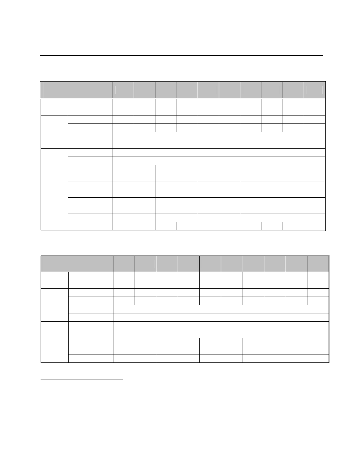
USER SELECTION GUIDE (ACtionMaster SPECIFICATIONS)
230V Class (1 ~ 30HP)
Model Number
SV xxx ACtionMaster - 2
HP 1 2 3 5 7.5 10 15 20 25 30 Motor
Rating1
kW 0.75 1.5 2.2 3.7 5.5 7.5 11 15 18.5 22
Capacity2 [kVA] 1.9 3.0 4.5 6.1 9.1 12.2 17.5 22.9 28.2 33.5
Output
Ratings
FLA [A] 5 8 12 16 24 32 46 60 74 88
Frequency 0 ~ 400 Hz (0-120Hz for Vector control)
Voltage 200 ~ 230 V
Voltage 3 Phase, 200 ~ 230 V (± 10 %) Input
Ratings
Frequency 50 ~ 60 Hz (±5 %)
Braking Circuit On the Board On the Board
Dynamic
Braking4
Average Braking
Torque
Max. Continuous
Baking Time
Max. Duty 3 % ED 2 % ED 5 % ED 5 % ED
Weight [lbs] 10.1 10.1 10.6 10.8 16.5 17.0 30.4 31.5 42.8 44.1
460V Class (1 ~ 30HP)
Model Number
SV xxx ACtionMaster - 4
HP 1 2 3 5 7.5 10 15 20 25 30 Motor
1
Rating
Output
Ratings
Ratings
Dynamic
Braking
kW 0.75 1.5 2.2 3.7 5.5 7.5 11 15 18.5 22
Capacity2 [kVA] 1.9 3.0 4.5 6.1 9.1 12.2 18.3 22.9 29.7 34.3
FLA [A] 2.5 4 6 8 12 16 24 30 39 45
Frequency 0 ~ 400 Hz (0-120Hz for Vector control)
Voltage 380 ~ 460 V
Voltage 3 Phase, 380 ~ 460 V (± 10 %) Input
Frequency 50 ~ 60 Hz (±5 %)
Braking Circuit
4
Max. Braking Torque 100% 100% 150% 150%
008 015 022 037 055 075 110 150 185 220
3
On the Board
(Optional Resistor)
Optional (Braking Unit, Resistor) 4
100% 100% 150% 150%
5 seconds 5 seconds 15 seconds Controlled by Braking Unit
008 015 022 037 055 075 110 150 185 220
3
On the Board On the Board
On the Board
(Optional Resistor)
5
Optional (Braking Unit, Resistor)
4
1
Indicates the maximum applicable capacity when using a 4 Pole motor.
2
Rated capacity (√ 3*V*I) is based on 220V for 200V class and 440V for 400V class.
3
Maximum output voltage will not be greater than the input voltage. Output voltage less than the input voltage may be programmed.
4
1~5 HP inverters have internal braking resistors as standard. 7.5~10 HP inverters utilize optional braking resistors.
i
Page 10
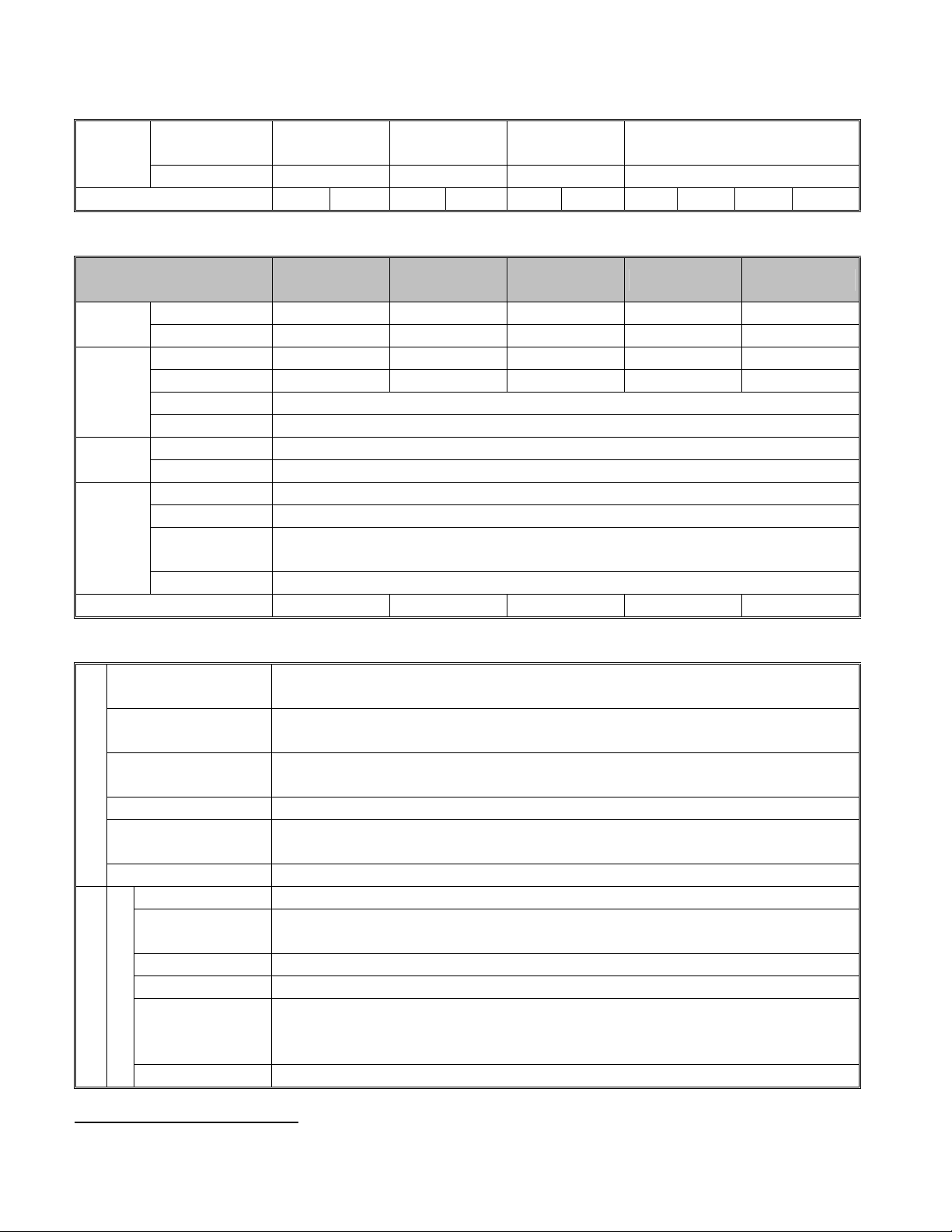
Max. Continuous
Baking Time
Max. Duty 3 % ED 2 % ED 5 % ED 5 % ED
Weight [lbs] 10.4 10.4 10.6 10.8 17.0 17.0 30.6 31.7 44.1 44.1
5 seconds 5 seconds 15 seconds Controlled by Braking Unit
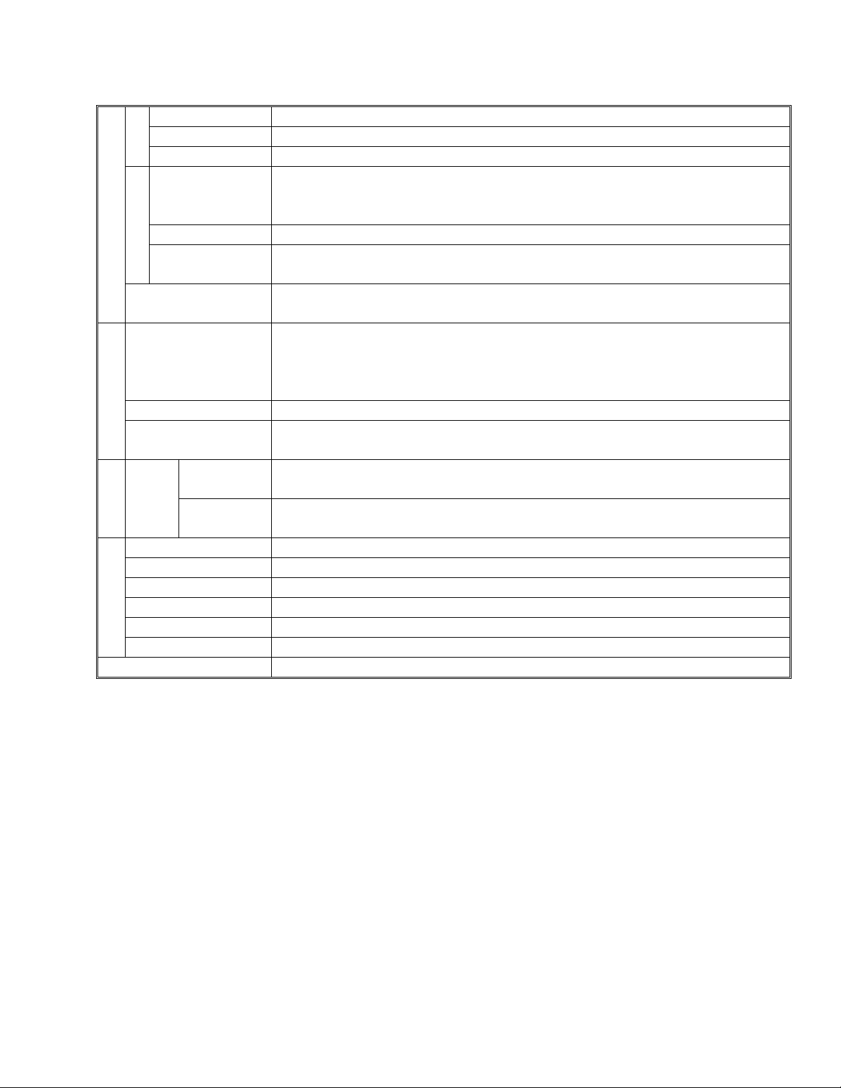
460V Class (40 ~ 100HP)
Model Number
SV xxx ACtionMaster - 4
Motor
Rating
Output
Ratings
Ratings
Dynamic
Braking
HP
1
kW
Capacity2 [kVA]
FLA [A]
Frequency 0 ~ 400 Hz (0-120Hz for Vector control)
Voltage 380 ~ 460 V
Voltage 3 Phase, 380 ~ 460 V (± 10 %) Input
Frequency 50 ~ 60 Hz (±5 %)
Braking Circuit Optional (Braking Unit, Resistor) 4
Max. Braking Torque 150%
Max. Continuous
4
Baking Time
Max. Duty 5 % ED
Weight [lbs] 45 45 63 63 68
300 370 450 550 750
40 50 60 75 100
30 37 45 55 75
45 56 68 82 100
61 75 91 110 152
3
Controlled by Braking Unit
5
Common Features Specification
Control Method V/F Control,
Sensorless Vector Control (Speed/Torque), Sensored Vector Control (Speed/Torque) Selectable
Frequency Setting
Resolution
Frequency Accuracy Digital: 0.01 % of Max. Output Frequency
CONTROL
V/F Ratio Linear, Square Pattern, User V/F
Overload Capacity 150 % of Rated Current for 1 Min., 200% of Rated Current for 0.5 sec. (Characteristic is Inversely
Torque Boost Manual Torque Boost (0 ~ 20 %), Auto Torque Boost
Operation Method Key / Terminal / Communication Operation
Frequency Setting Analog: 0 ~ 10V / 4 ~ 20mA / Additional ports (VR: +12V, 10mA, V2: 0-10V) for Sub-Boards
Start Signal Forward, Reverse
Multi-Step Up to 8 Speeds can be Set (Use Multi-Function Terminal)
Multi Step
Input Signal
OPERATION
Accel/Decel Time
Emergency Stop Instantly Interrupts the Inverter Output
Digital Reference: 0.01 Hz (Below 100 Hz), 0.1 Hz (Over 100 Hz)
Analog Reference: 0.03 Hz / 60 Hz
Analog: 0.1 % of Max. Output Frequency
Proportional to Time)
Digital: Keypad
0 ~ 6,000 sec, Up to 4 Types can be Set and Selectable for Each Setting (Use Multi- Function
Terminal)
Accel/Decel Pattern: Linear, U-Curve, S-Curve Selectable
5
5
Refer to Chapter 7 Options for DBU and DB Resistors
ii
Page 11
Cooling Method Forced Air Cooling
Jog Jog Operation
Auto Operation Operates via Internal Sequence by Setting Multi-Function Terminal (5 Way * 8 Step)
Fault Reset Trip Status is Removed when Protection Function is Activated
Operating Status Frequency Detection Level, Overload Alarm, Stalling, Over Voltage, Under Voltage, Inverter
Overheating, Running, Stop, Constant Speed, Inverter By-Pass, Speed Searching, Auto-Operation
Step, Auto-Operation Sequence
Fault Output Contact Output (30A, 30C, 30B) – AC 250V 1A, DC 30V 1A
Output Sig.
Indicator(FM,LM) Choose 1 from Output Frequency, Output Current, Output Voltage, DC Voltage, Output Torque
Output Voltage: 0 ~ 10V (for FM: Linear output, 15V Max., LM), Pulse output: 500Hz (for LM).
Operation Function DC Braking, Frequency Limit, Frequency Jump, Second Function, Slip Compensation, Reverse
Rotation Prevention, Auto Restart, Inverter By-Pass, Auto-Tuning, PID Control
Inverter Trip Over Voltage, Under Voltage, Over Current, Fuse Open, Ground Fault, Inverter Overheating, Motor
Overheating, Output Phase Open,
Overload Protection, External Fault 1, 2, Communication Error, Loss of Speed Command, Hardware
Fault, Option Fault etc.
Inverter Alarm Stall Prevention, Overload Alarm, Temperature Sensor Fault
Momentary Power Loss Less than 15msec: Continuous Operation,
Protective Function
More than 15msec: Auto Restart Possible
Keypad
Display
Operation
Information
Trip
Output Frequency, Output Current, Output Voltage, Frequency Value Setting, Operating Speed, DC
Voltage, Output Torque
Indicates a Fault when the Protection Function activates, Retains Up to 5 Faults
Information
Ambient Temperature
Storage Temperature
-10 °C ~ 40 °C (14 °F ~ 104 °F), CE Certification: 41 °F ~ 104 °F (5 °C ~ 40 °C)
-20 °C ~ 65 °C (-4 °F ~ 149 °F)
Ambient Humidity Less Than 90 % RH Max. (Non-Condensing), CE Certification: 5 ~85% (Non-Condensing)
2
Altitude - Vibration
Environment
Air Pressure 86 ~ 106kPa
Below 1,000m or 3,300ft above sea level · Below 5.9m/sec
(=0.6g)
Application Site No Corrosive Gas, Combustible Gas, Oil Mist, or Dust
iii
Page 12

Page 13
CHAPTER 1 - INSTALLATION
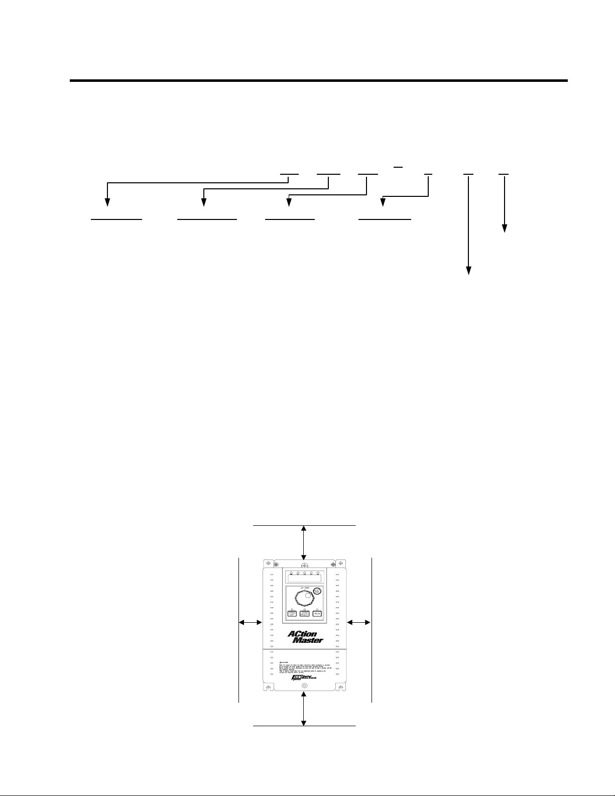
1.1 Inspection
Inspect the inverter for any damage that may have occurred during shipping.
Check the nameplate on the inverter. Verify the inverter unit is the correct one for the application. The numbering
system for the inverter is as shown below.
CMC Inverter Motor Capacity Series Name Input Voltage
008: 1 HP 185: 25 HP 2 : 200 ~ 230V (±±±±10%) 50/60Hz
015: 2 HP 220: 30 HP 4 : 380 ~ 460V (±±±±10%) 50/60Hz UL Listed
022: 3 HP 300: 40 HP (UL508C)
037: 5 HP 370: 50 HP
055: 7.5 HP 450: 60 HP Without
075: 10 HP 550: 75 HP Keypad
110: 15 HP 750: 100 HP
150: 20 HP
1.2 Environmental Conditions
Verify ambient condition for the mounting location.
- Ambient temperature should not be below 14ºF (-10ºC) or exceed 104ºF (40ºC).
- Relative humidity should be less than 90% (non-condensing).
- Altitude should be below 3,300ft (1,000m).
Do not mount the inverter in direct sunlight and isolate it from excessive vibration.
If the inverter is going to be installed in an environment with high probability of penetration of dust, it must be located
inside watertight electrical boxes, in order to get the suitable IP degree.
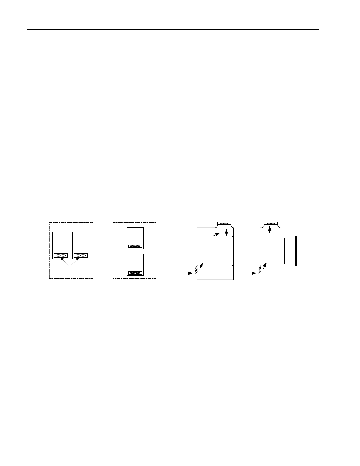
1.3 Mounting
The inverter must be mounted vertically with sufficient horizontal and vertical space between adjacent equipment
(A= Over 6" (150mm), B= Over 2" (50mm)).
B
008SV AC 2 N U
A
B
A
1-1
Page 14
Chapter 1 - Installation
1.4 Other Precautions
Do not carry the inverter by the front cover.
Do not install the inverter in a location where excessive vibration is present. Be cautious when installing on presses or
moving equipment.
The life span of the inverter is greatly affected by the ambient temperature. Install in a location where temperature are
within permissible limits (- 10 ~ 40 ℃).
The inverter operates at high-temperatures - install on a non-combustible surface.
Do not install the inverter in high-temperature or high-humidity locations.
Do not install the inverter in a location where oil mist, combustible gas, or dust is present. Install the inverter in a clean
location or in an enclosed panel, free of foreign substance.
When installing the inverter inside a panel with multiple inverters or a ventilation fan, use caution.
If installed incorrectly, the ambient temperature may exceed specified limits.
Install the inverter using screws or bolts to insure the inverter is firmly fastened.
Panel Panel
Inverter
Inverter
[When installing several inverters in a panel]
Inverter
Cooling fan
GOOD (O)
Inverter
BAD (X)
Ventilating fan
GOOD (O)
[When installing a ventilating fan in a panel]
BAD (X)
1-2
Page 15
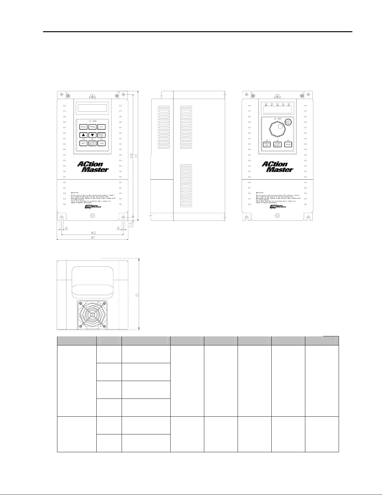
1.5 Dimensions
Frame # 1: 1 ~ 5 HP
Frame # 2: 7.5 ~ 10 HP
Chapter 1 - Installation
Frame HP Model Number W1 W2 H1 H2 D1
1 SV008ACtionMa
ster-2/4
2 SV015ACtionMa
Frame # 1
ster-2/4
3 SV022ACtionMa
150
(5.91)
130
(5.12)
284
(11.18)
269
(10.69)
156.5
(6.16)
ster-2/4
5 SV037ACtionMa
ster-2/4
7.5 SV055ACtionMa
Frame # 2
ster-2/4
10 SV075ACtionMa
200
(7.87)
180
(7.09)
355
(13.98)
340
(13.39)
182.5
(7.19)
ster-2/4
1-3
Page 16

Chapter 1 - Installation
BLANK
1-4
Page 17
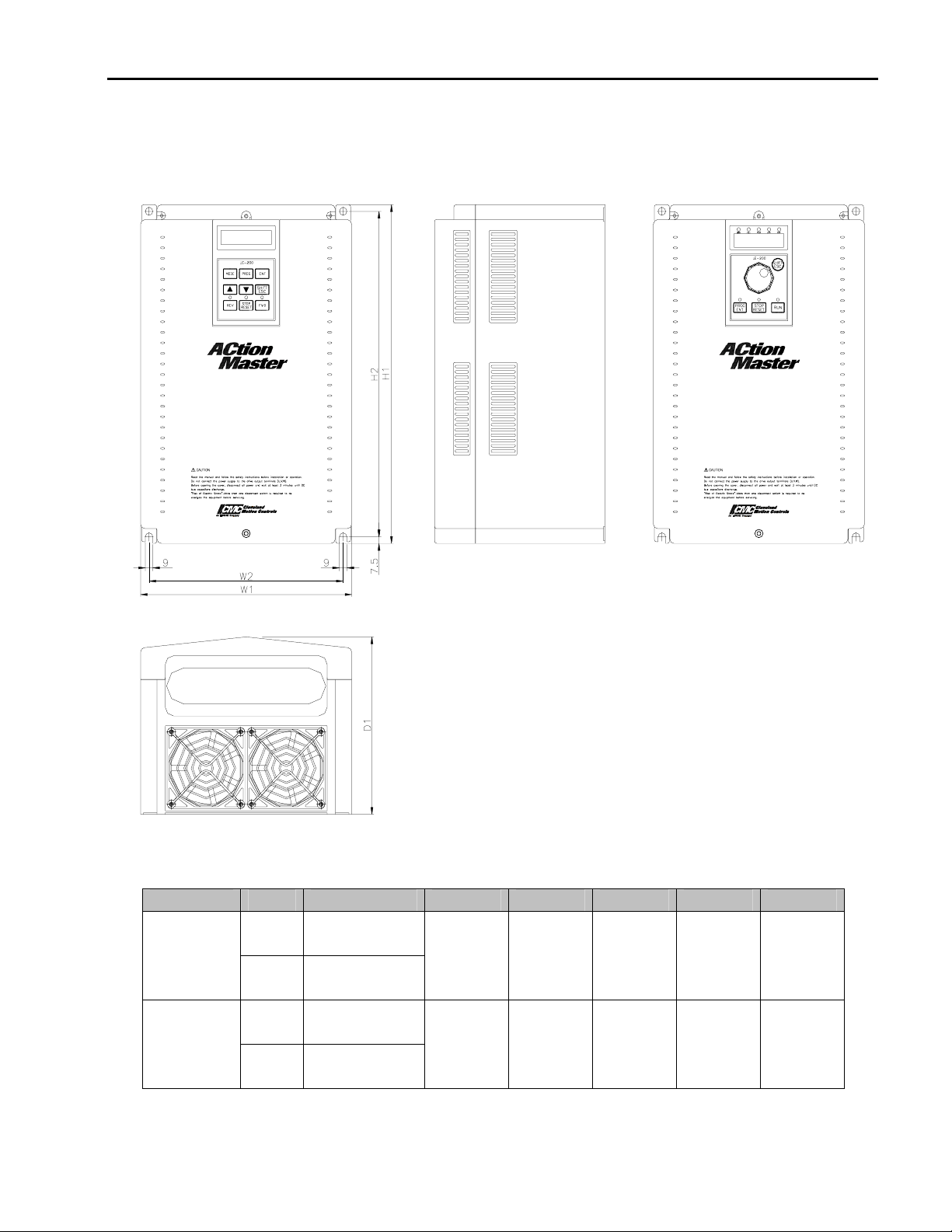
Frame # 3: 15 ~ 20 HP
Frame # 4: 25 ~ 30 HP
Chapter 1 - Installation
Frame HP Model Number W1 W2 H1 H2 D1
15 SV110ACtionMa
Frame # 3
ster-2/4
20 SV150ACtionMa
250
(9.84)
230
(9.06)
385
(15.16)
ster-2/4
25 SV185ACtionMa
Frame # 4
ster-2/4
30 SV220ACtionMa
304
(11.97)
284
(11.18)
460
(18.11)
ster-2/4
1-5
mm (inches)
370
(14.57)
445
(17.52)
201
(7.91)
234
(9.21)
Page 18

Chapter 1 - Installation
BLANK
1-6
Page 19
2
4
A
y
3
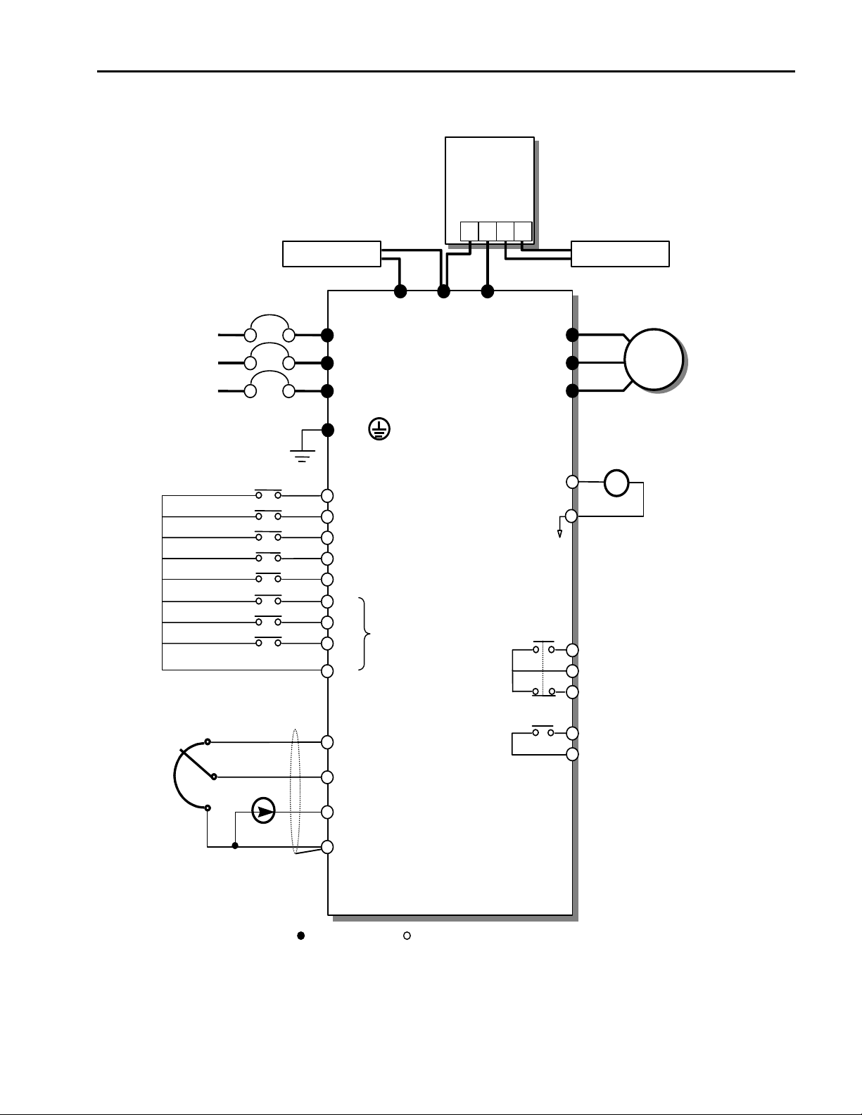
1.6 Basic Wiring
Chapter 1 - Installation
MCCB(OPTION)
φ
3
30/460 V
50/60 Hz
Forward Run/Stop
Reverse Run/Stop
Inverter Di sable
Fault Reset
Jog
Multi-function Input 1
Multi-function Input 2
Multi-function Input 3
Common Terminal
Dynamic
Braking Unit
(Optional)
DB Unit(Optional)
DC Bus Choke (Optional)
P N B1 B2
DB Resitor
DC Bus Choke DB Resistor
1
1
R
S
T
P1
1
P2
N
U
V
W
G ( )
FM
FX
RX
BX
RST
JOG
P1
P2
P3
CM
Factory Setting:
‘Speed-L’
‘Speed-M’
‘Speed-H’
(N.O.)
(N.C.) B
5G
Fault output relay
C
lless than AC250V, 1A
lless than DC30V, 1A
+
MOTOR
FM
Output Frequency Meter
(0~10V Linear)
Potentiometer
(1 kohm, 1/2W)
Speed signal Input
Shield
Power suppl
VR
speed signal:
+ 11V, 10mA
Speed signal input:
V1
0 ~ 10V
Speed signal input:
I
4 ~20mA (250ohm)
Common for
5G
2
Note) Main Circuit Terminals Control Circuit Terminals.
1. The terminal configuration varies depend on the model number . Pleas e refer to the ‘1.7 Power terminals’.
2. Analog speed command may be set by Voltage, Current or both.
3. When installing the DC Reactor, the Common Busbar between P1 and P2 must be removed.
4. 1 ~ 10 HP inverters have on-board braki ng circuit. Braking resistors are only included for 1 ~ 5 inverters.
15 ~ 30 HP inv erters need optional braking unit and resi stor for dynamic braking.
VR, V1, I
for
AXA
AXB
Multi-function output relay1
lless than AC250V, 1A
lless than DC30V, 1A
Factory setting: ‘Run’
1-7
Page 20
Chapter 1 - Installation
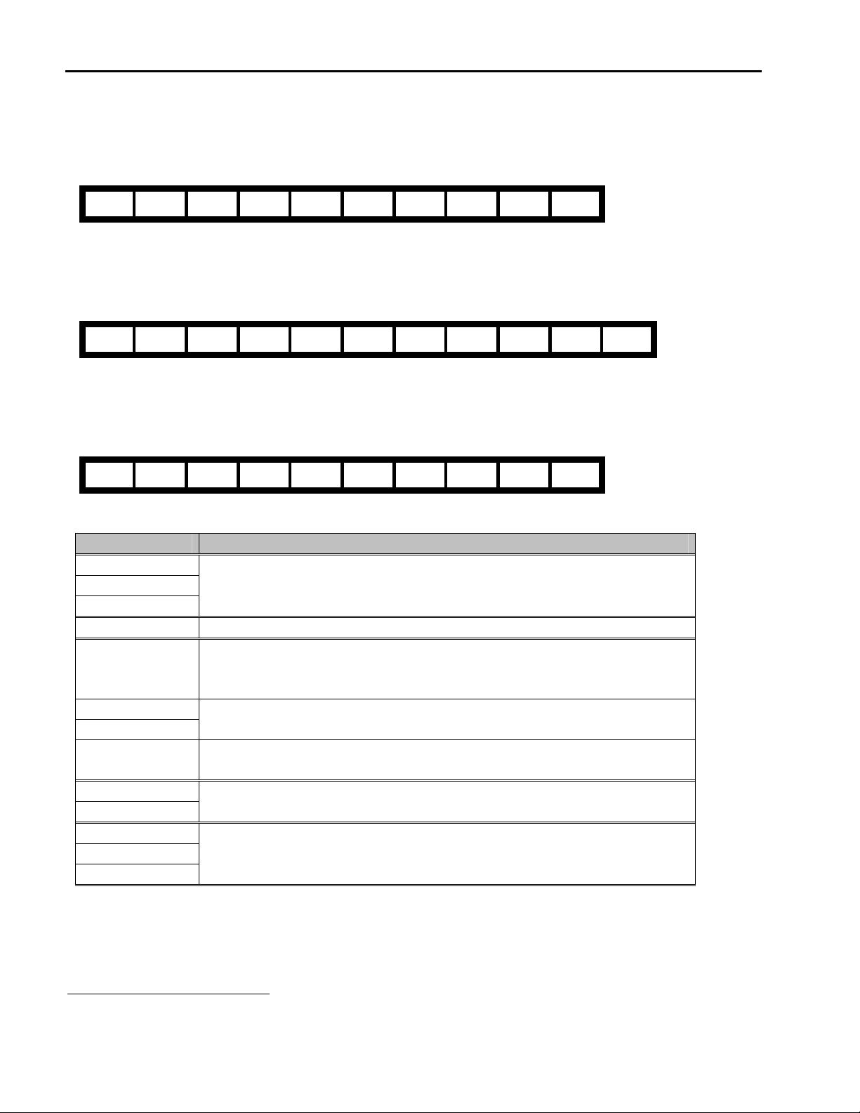
1.7 Power Terminals
Type A Configuration: 1 ~ 5 HP (SV008ACtionMaster-2, SV015ACtionMaster-2, SV022ACtionMaster-2,
SV037ACtionMaster-2, SV008ACtionMaster-4, SV015ACtionMaster-4, SV022ACtionMaster-4, SV037ACtionMaster-4)
R S T G N B1 B2 U V W
Type B Configuration: 7.5 ~ 10 HP (SV055ACtionMaster-2, SV075ACtionMaster-2, SV055ACtionMaster-4,
SV075ACtionMaster-4)
R S T G P N B1 B2 U V W
Type C Configuration: 15 ~ 30 HP (SV110ACtionMaster-2, SV150ACtionMaster-2, SV185ACtionMaster-2,
SV220ACtionMaster-2, SV110ACtionMaster-4, SV150ACtionMaster-4, SV185ACtionMaster-4, SV220ACtionMaster-4)
R S T G P1 P2 N U V W
Symbols Functions
R
S
T
G Earth Ground
P
P1
P2
N
B1
B2
U
V
W
“Suitable for use on a circuit capable of delivering not more than 10,000 rms symmetrical amperes,
240 volts maximum for 230V class models and 480 volts maximum for 460V class models.”
AC Line Voltage Input
(3 Phase, 200 ~ 230VAC or 380 ~ 460VAC)
Positive DC Bus Terminal
DB Unit (P-P
5
) Connection Terminals
(DB Unit may be added when more braking duty (More than 30%ED) is required)
External DC Reactor (P1-P2) and DB Unit (P2-P
6
) Connection Terminals
Negative DC Bus Terminal
DB Unit (N-N
7
) Connection Terminal
Dynamic Braking Resistor (B1-B2) Terminals
3 Phase Power Output Terminals to Motor
(3 Phase, 200 ~ 230VAC or 380 ~ 460VAC)
6
This P terminal is provided on optional Dynamic Braking Unit.
7
This N terminal is provided on optional Dynamic Braking Unit.
1-8
Page 21
Chapter 1 - Installation
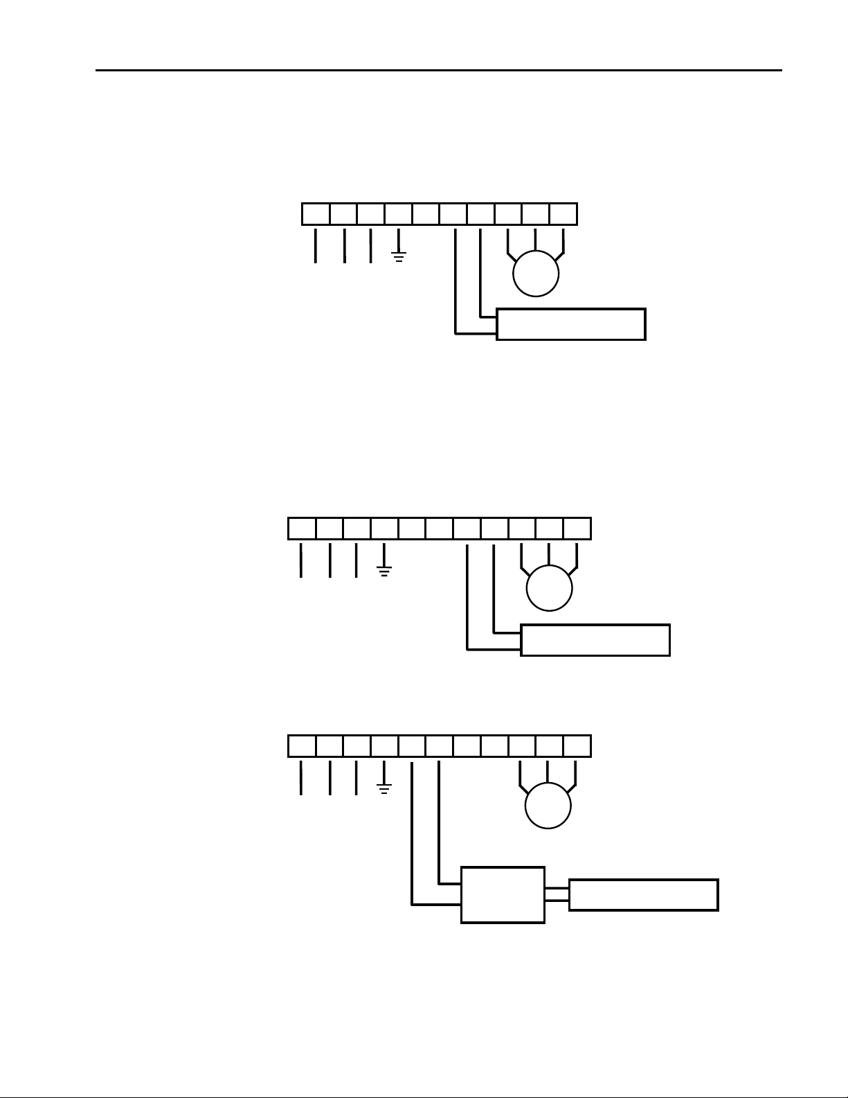
1.7.1 Type A Configuration
As standard on the ACtionMaster inverter, this type of configuration has internal dynamic braking resistor of 3% ED. When
an application requires more braking duty, an external dynamic braking resistor may be connected instead of the internal
resistor.
R S T G N B1 B2 U V W
3 Phase
Power Input
Motor
Dynamic Braking Resistor
Figure 1 – Type A Dynamic Braking Resistor Installation
1.7.2 Type B Configuration
A Dynamic Braking Resistor or a Dynamic Braking Unit may be added to ACtionMaster series inverters that have a Type B
configuration power terminal strip. As standard, this type of configuration has in
R S T G P N B1 B2 U V W
3 Phase
Power Input
Motor
Dynamic Braking Resistor
Figure 2 – Type B Dynamic Braking Resistor Installation
R S T G P N B1 B2 U V W
3 Phase
Power Input
Motor
Dynamic
Braking Unit
Dynamic Braking Resistor
Figure 3 – Type B Additional Dynamic Braking Unit and Resistor Installation
1-9
Page 22

Chapter 1 - Installation
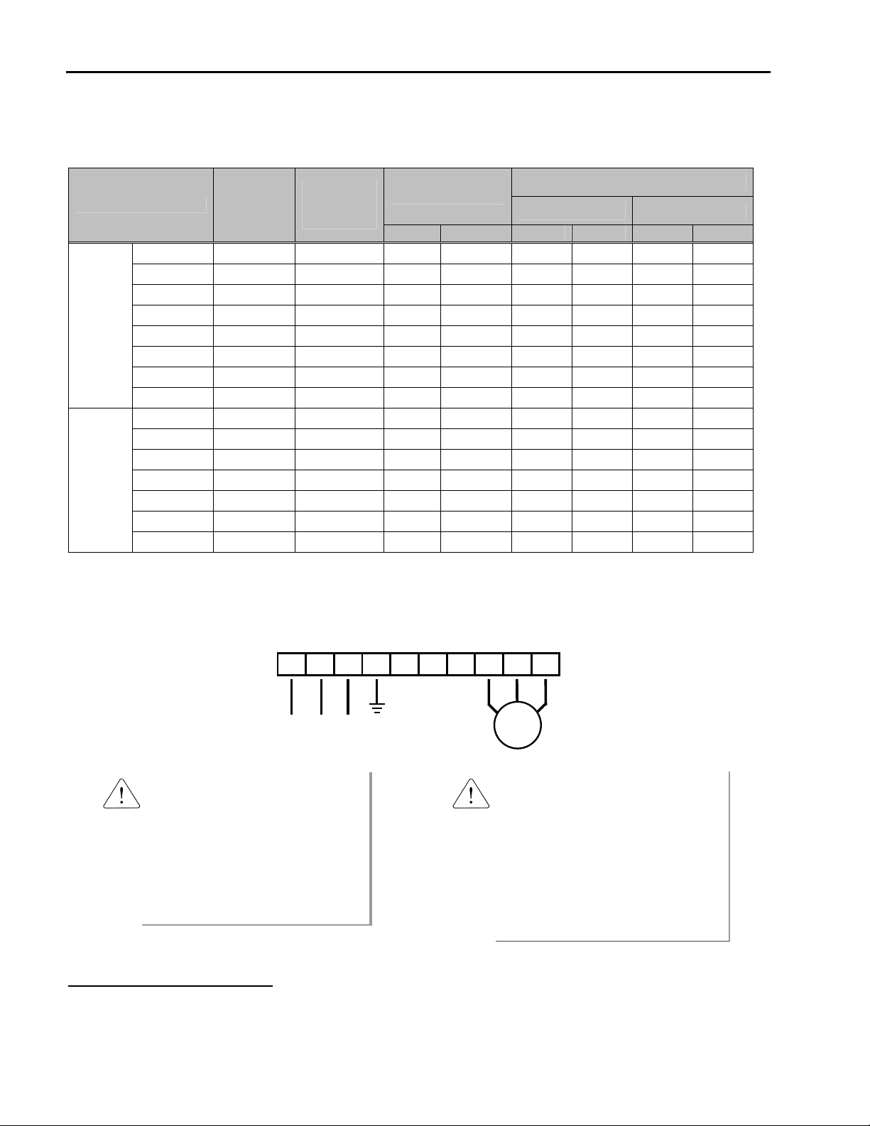
1.7.3 Type C Configuration
A Dynamic Braking Unit or a DC Bus Choke or both of them may be added to ACtionMaster series inverters that have a
Type A Configuration power terminal strip.
Jumper Between P1 and P2 Must Be Removed in Order
to Install a DC Bus Choke.
R S T G P1 P2 N U V W
Figure 4 – Type C Dynamic Braking Unit, DC Bus Choke Installation
3 Phase
Power Input
Motor
Dynamic
Braking
Unit
Dynamic Braking Resistor
DC Bus Choke
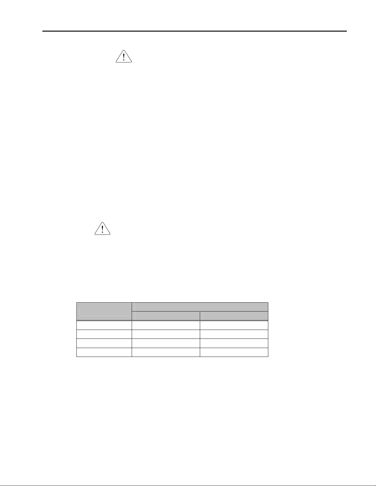
WARNING
Normal stray capacitance between the inverter chassis and the power devices inside the inverter and AC line
can provide a high impedance shock hazard. Refrain from applying power to the inverter if the inverter frame
(Power terminal G) is not grounded.
1-10
Page 23
Chapter 1 - Installation
1.7.4 Wiring Power Terminals
Wiring Precautions
The internal circuits of the inverter will be damaged if the incoming power is connected and applied to output terminals
(U, V, W).
Use ring terminals with insulated caps when wiring the input power and motor wiring.
Do not leave wire fragments inside the inverter. Wire fragments can cause faults, breakdowns, and malfunctions.
For input and output, use wires with sufficient size to ensure voltage drop of less than 2%.
Motor torque may drop of operating at low frequencies and a long wire run between inverter and motor.
When more than one motor is connected to one inverter, total wire length should be less than 500m (1,640ft). Do not
use a 3-wire cable for long distances. Due to increased leakage capacitance between wires, over-current protective
feature may operate or equipment connected to the output side may malfunction.
Connect only recommended braking resistor between the B1 and B2 terminals. Never short B1 and B2 terminals.
Shorting terminals may cause internal damage to inverter.
The main circuit of the inverter contains high frequency noise, and can hinder communication equipment near the
inverter. To reduce noise, install line noise filters on the input side of the inverter.
Do not use power factor capacitor, surge killers, or RFI filters on the output side of the inverter. Doing so may damage
these components.
Always check whether the LCD and the charge lamp for the power terminal are OFF before wiring terminals. The
charge capacitor may hold high-voltage even after the power is disconnected. Use caution to prevent the possibility of
personal injury.
Grounding
The inverter is a high switching device, and leakage current may flow. Ground the inverter to avoid electrical shock.
Use caution to prevent the possibility of personal injury.
Connect only to the dedicated ground terminal of the inverter. Do not use the case or the chassis screw for grounding.
The protective earth conductor must be the first one in being connected and the last one in being disconnected.
As a minimum, grounding wire should meet the specifications listed below. Grounding wire should be as short as
possible and should be connected to the ground point as near as possible to the inverter.
Inverter Capacity
Grounding wire Sizes, AWG (mm²
200V Class 400VClass
Below 5 HP 12 ((3.5) 14 (2)
7.5 ~ 10 HP 10 (5.5) 12 (3.5)
15 ~ 20 HP 6 (14) 8 (8)
25 ~ 30 HP 4 (22) 6 (14)
²)
²²
1-11
Page 24
Chapter 1 - Installation
Wires and Terminal Lugs
Refer to the following table for wires, terminal lugs, and screws used to connect the inverter power input
(R, S, T) and output (U, V, W).
9
Wire
Inverter Capacity
1 ~ 3 HP M3.5 15 / 10 2-4 2-4 2 2 14 14
200V
Class
1 ~ 5 HP M3.5 15 / 10 2-4 2-4 2 2 14 14
400V
Class
Terminal
Screw Size
5 HP M3.5 15 / 10 2-4 2-4 3.5 3.5 12 12
7.5 HP M4 15 / 10 5.5-5 5.5-5 5.5 5.5 10 10
10 HP M4 15 / 10 14-5 8-5 14 8 6 8
15 HP M5 26 / 18 14-5 14-5 14 14 6 6
20 HP M5 26 / 18 22-6 22-6 22 22 4 4
25 HP M6 45 / 31 38-8 38-8 30 30 2 2
30 HP M6 45 / 31 38-8 38-8 38 30 2 2
7.5 HP M4 15 / 10 5.5-5 5.5-5 3.5 2 12 14
10 HP M4 15 / 10 14-5 8-5 3.5 3.5 12 12
15 HP M5 26 / 18 14-5 14-5 5.5 5.5 10 10
20 HP M5 26 / 18 22-6 22-6 14 8 6 8
25 HP M6 45 / 31 38-8 38-8 14 8 6 8
30 HP M6 45 / 31 38-8 38-8 22 14 4 6
Screw
8
Torque
(Kgf·cm)/lb-in
Ring Terminals
mm²
R,S,T U,V,W R,S,T U,V,W R,S,T U,V,W
Power and Motor Connection
R S T G N B1 B2 U V W
3 Phase
Power Input
Motor
Power supply must be connected
to the R, S, and T terminals.
Connecting it to the U, V, and W
terminals causes internal damages
to the inverter. Arranging the phase
sequence is not necessary.
Motor should be connected to the
U, V, and W terminals.
If the forward command (FX) is on,
the motor should rotate counter
clockwise when viewed from the load
side of the motor. If the motor rotates
in the reverse, switch the U and V
terminals.
AWG
8
Apply the rated torque to terminal screws. Loose screws can cause of short circuit or malfunction. Tightening the screws too much can
damage the terminals and cause a short circuit or malfunction.
9
Use copper wires only with 600V, 75℃ ratings.
1-12
Page 25
1.8 Control Terminals
Chapter 1 - Installation
30A 30C 30B AXA AXC
P1 P2 P3 FX RX NC VR V1
JOG CM CM BX RST I FM 5G
Type Symbol Name Description
P1, P2, P3
JOG
Starting Contact Function Select
RST Fault Reset Used for Fault Reset.
Input signal
Analog frequency setting
Analog
30A
30C
Output signal
30B
Contact
AXA, AXC
Multi-Function Input
1, 2, 3
FX Forward Run Command Forward Run When Closed and Stopped When Open.
RX Reverse Run Command Reverse Run When Closed and Stopped When Open.
Jog Frequency
Reference
BX Emergency Stop
!
CM Sequence Common Common Terminal for Contact Inputs.
NC - Not Used.
VR
V1
I
5G
FM
Frequency Setting Power
(+12V)
Frequency Reference
(Voltage)
Frequency Reference
(Current)
Frequency Setting
Common Terminal
Analog Output (0~10V)
(For External Monitoring)
Fault Contact Output
Multi-Function Output
Relay
Used for Multi-Function Input Terminal.
(Factory default is set to “Step Frequency 1, 2, 3”.)
Runs at Jog Frequency when the Jog Signal is ON. The Direction is set by
the FX (or RX) Signal.
When the BX Signal is ON the Output of the Inverter is Turned Off. When
Motor uses an Electrical Brake to Stop, BX is used to Turn Off the Output
Signal. When BX Signal is OFF (Not Turned Off by Latching) and FX Signal
(or RX Signal) is ON, Motor continues to Run.
Used as Power for Analog Frequency Setting.
Maximum Output is +12V, 100mA.
Used for 0-10V Input Frequency Reference. Input Resistance is 20 KΩ
Used for 4-20mA Input Frequency Reference. Input Resistance is 250 Ω
Common Terminal for Analog Frequency Reference Signal and FM
(Frequency Meter).
Outputs One of the Following: Output Frequency, Output Current, Output
Voltage, DC Link Voltage and Torque. Default is set to Output Frequency.
Maximum Output Voltage and Output Current are 0-12V and 1mA.
Activates when Protective Function is Operating. AC250V, 1A or less;
DC30V, 1A or less.
Fault: 30A-30C Closed (30B-30C Open)
Normal: 30B-30C Closed (30A-30C Open)
Use After Defining Multi-Function Output Terminal. AC250V, 1A or less;
DC30V, 1A or less.
Comm. CN3 Communication Port Keypad Connection Port.
Tightening Torque: 5.2 lb-in maximum.
1-13
Page 26
Chapter 1 - Installation
1.8.1 Wiring Control Terminals
Wiring Precautions
CM and 5G terminals are insulated to each other. Do not connect these terminals with each other and do not connect
these terminals to the power ground.
Use shielded wires or twisted wires for control circuit wiring, and separate these wires from the main power circuits
and other high voltage circuits.
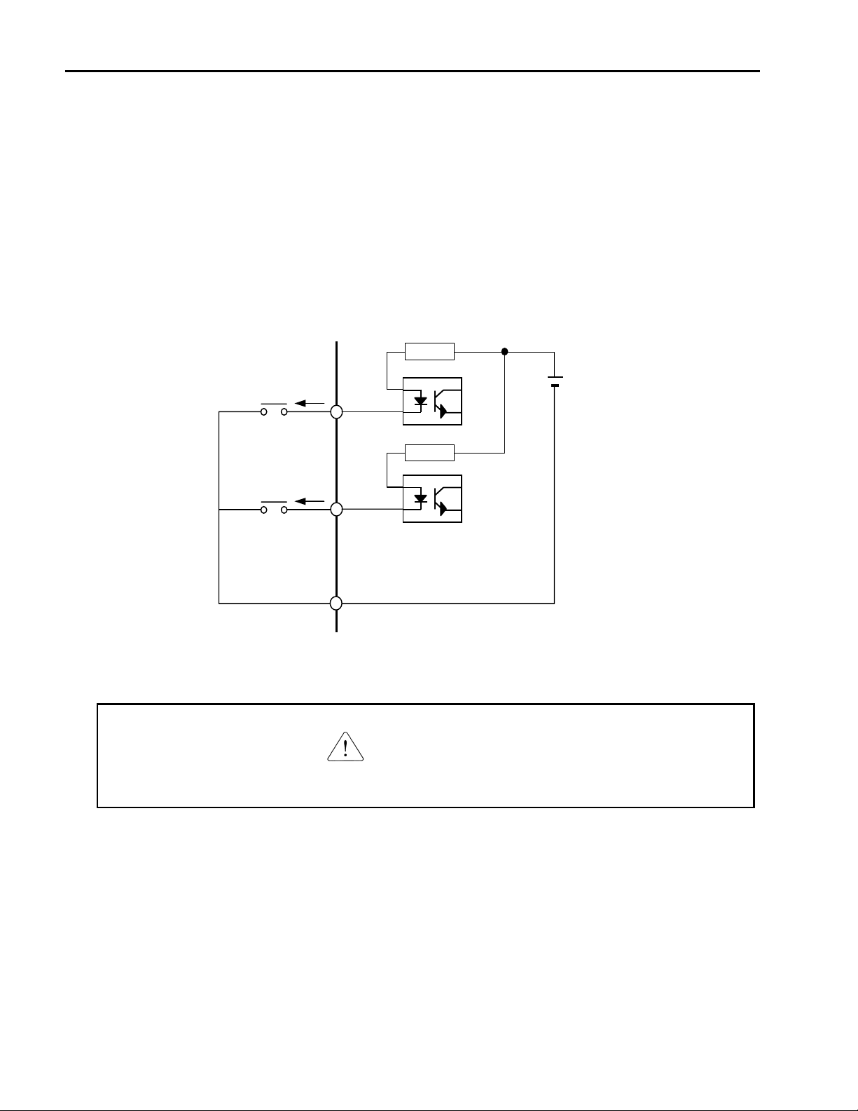
Control Circuit Terminal
The control input terminal of the control circuit is ON when the circuit is configured to the current flows out of the
terminal, as shown in the following illustration. CM terminal is the common terminal for the contact input signals.
Current
FX
Resistor
24 VDC
Resistor
RX
CM
External Sequence
Inverter Circuitry
CAUTION
Do not apply voltage to any control input terminals (FX, RX, P1, P2, P3, JOG, BX, RST, CM).
1-14
Page 27
Chapter 1 - Installation
r
t
t
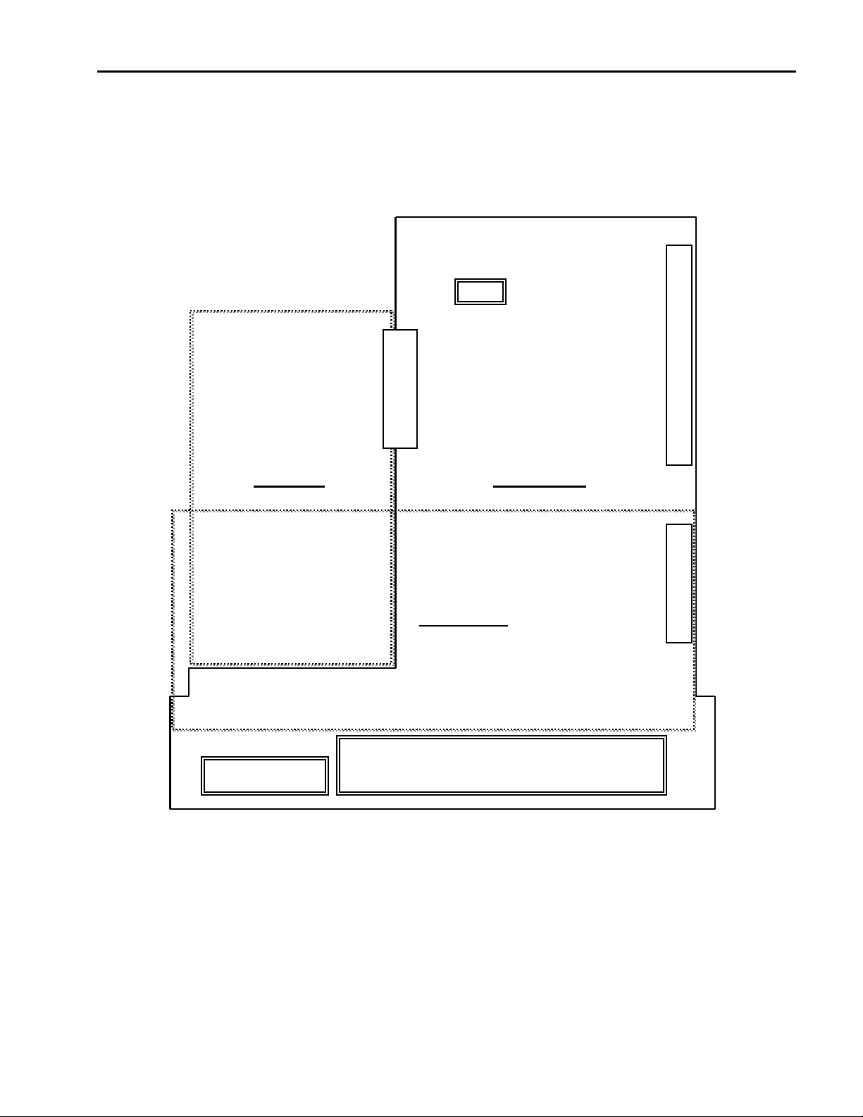
1.8.2 Keypad Connection
Connect keypad to the keypad connector as illustrated below. The LCD output will not be displayed on the keypad if the
keypad is not connected properly.
Keypad Connector
(CN3)
Sub-Board Connecto
CN5
Power Supply Input,
Gate Drive Signal Outpu
Connector Socke
Sub-Board
Control Board
Option Board
Option Board Connector
(CN2)
Relay Output
Terminal Block
Control Terminal Block
1-15
Page 28

Chapter 1 - Installation
Notes:
1-16
Page 29
CHAPTER 2 - OPERATION
The ACtionMaster series inverter has seven parameter groups separated according to their applications as indicated in the
following table.
The ACtionMaster series inverter provides two kinds of keypad. One is of 32-character alphanumeric LCD keypad and the
other is of 7-Segment LED keypad.
2.1 Parameter Groups
Parameter
Group
Drive Group DRV ‘DRV’ LED
Function 1 Group FU1 ‘FU1’ LED
Function 2 Group FU2 ‘FU2’ LED
Input / Output
Group
LCD Keypad
(Upper left Corner)
I/O ‘I/O’ LED
7-segment Keypad
(LED is lit)
Description
Command Frequency, Accel/Decel Time etc.
Basic Parameters
Max. Frequency, Amount of Torque Boost etc.
Basic Related Parameters
Frequency Jumps, Max./Min. Frequency Limit etc.
Basic Application Related Parameters
Multi-Function Terminal Setting, Auto Operation etc.
Parameters needed for Sequence Operation
Sub-Board Group EXT ‘EXT’ LED Displayed when Sub-Board is Installed.
Option Group COM ‘I/O’ + ‘EXT’ LED Displayed when Option Board is Installed.
Application Group APP
Refer to the function descriptions in Chapter 6 for detailed description of each group.
‘FU2’ + ‘I/O’ + ‘EXT’
LED
Traverse, MMC (Multi-Motor Control), Draw etc.
Application Related Parameters
2-1
Page 30
Chapter 2 - Operation
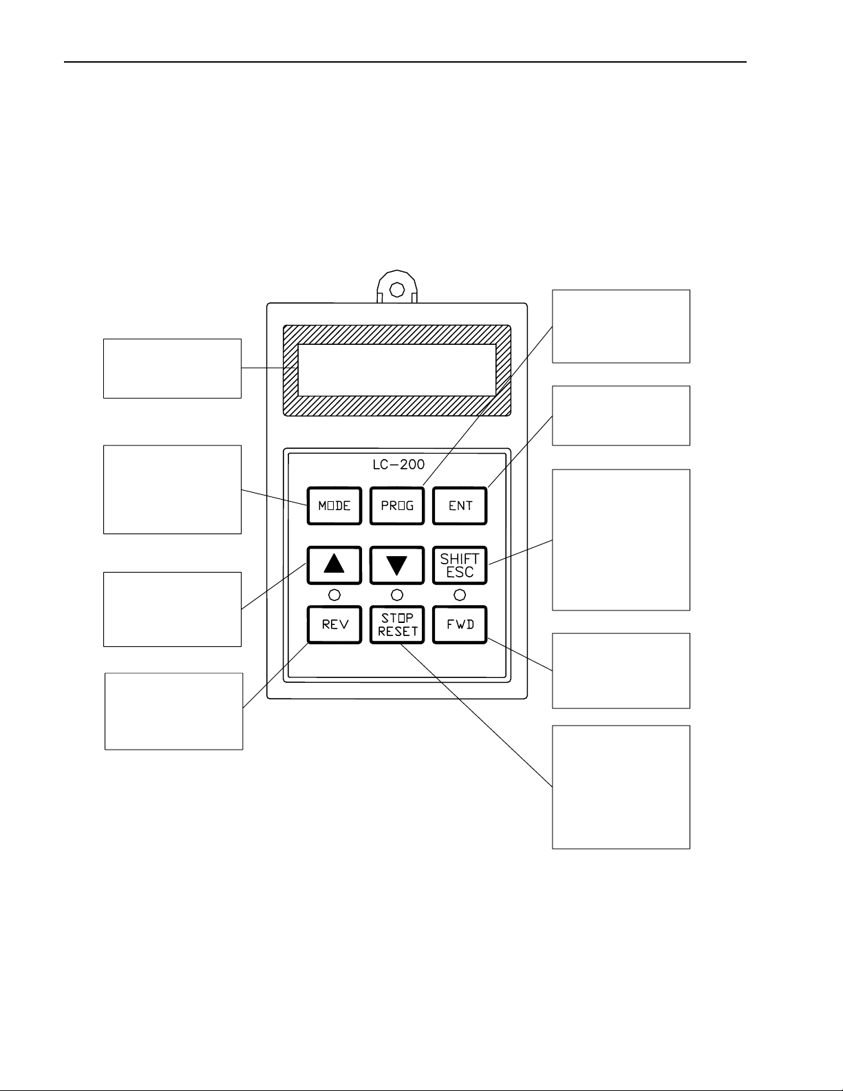
2.2 LCD Keypad
LCD keypad can display up to 32 alphanumeric characters, and various settings can be checked directly from the display.
The following is an illustration of the keypad.
32 character, back light,
LCD display. The back
light is adjustable.
The Mode Button moves
you through the seven
program groups: DRV,
FUN1, FUN2, I/O, (EXT),
COM, and APP
The Up and Down
Arrows
are used to
move through and
change data.
Reverse Run Button.
The Reverse Run LED
blinks when the drive
Accels or Decels.
The Program Button is
used to go into
programming mode to
change data.
The Enter Button is
used to enter changed
data within a parameter.
[SHIFT] This button is
used to move cursor
across display in
programming mode.
[ESC] This button is used
to move the program
code to DRV 00 form any
program code.
Forward Run Button.
The Forward Run LED
blinks when the drive
Accels or Decels.
Stop Button is used to
stop the drive from
running.
The
Reset Button is
used to reset Faults.
The
LED blinks when
there is a fault.
2-2
Page 31

Chapter 2 - Operation
2.2.1 LCD Keypad Display
2) Run/Stop Source
1) Parameter group
3) Frequency Setting Source
4) Output Current
DRV¢ºT/K 0.0 A
00 STP 0.00 Hz
Displays Description
1) Parameter Group Displays the parameter group. There are DRV, FU1, FU2, I/O, EXT, COM, APP groups.
2) Run/Stop Source Displays the source of motor Run and Stop
3) Frequency Setting
Source
4) Output Current Displays the Output Current during operation.
5) Parameter Code Displays the code of a group. Use the ▲(Up), ▼(Down) key to move through 0~99 codes.
6) Operating Status Displays the operation information.
7) Drive Output Frequency
Command Frequency
5) Parameter Code
6) Operating Status
K: Run/Stop using FWD, REV buttons on keypad
T: Run/Stop using control terminal input FX, RX
O: Run/Stop via option board
Displays the source of command frequency setting
K: Frequency setting using keypad
V: Frequency setting using V1 (0 ~10V) or V1 + I terminal
I: Frequency setting using I (4 ~ 20mA) terminal
U: Up terminal input when Up/Down operation is selected
D: Down terminal input when Up/Down operation is selected
S: Stop status when Up/Down operation is selected
O: Frequency setting via Option board
X: Frequency setting via Sub board
J: Jog terminal input
1 ~ 8: Step frequency operation
* During Auto operation, 2) and 3) display the ‘sequence number/step’.
STP: Stop Status
FWD: During Forward operation
REV: During Reverse operation
DCB: During DC Braking
LOP: Loss of Reference from Option Board (DPRAM fault)
LOR: Loss of Reference from Option Board (Communication network fault)
LOV: Loss of Analog Frequency Reference (V1: 0~10V)
LOI: Loss of Analog Frequency Reference (I: 4~20mA)
LOS: Loss of Reference from Sub-Board
Displays the Output Frequency during run.
Displays the Command Frequency during stop.
7) Drive Output Frequency During Run,
Command Frequency During Stop
2-3
Page 32

Chapter 2 - Operation
2.2.2 Procedure for Setting Data (LCD Keypad)
1. Press [MODE] key until the desired parameter group is displayed.
2. Press [▲] or [▼] keys to move to the desired parameter code. If you know the desired parameter code, you can set
the code number of each parameter group in “Jump code”, except DRV group.
3. Press [PROG] key to go into the programming mode, the cursor starts blinking.
4. Press [SHIFT/ESC] key to move the cursor to the desired digit.
5. Press [▲] or [▼] keys to change the data.
6. Press [ENT] key to enter the data. The cursor stops blinking.
Note: Data cannot be changed when:
1) The parameter is not adjustable during the inverter is running. (Refer to the function table in Chapter 5), or,
2) Parameter Lock function is activated in FU2-94 [Parameter Lock].
2-4
Page 33

Chapter 2 - Operation
r
r
y
%
2.2.3 Parameter Navigation (LCD Keypad)
The parameter group moves directly to DRV group by pressing [SHIFT/ESC] key in any parameter code.
Drive Group FU1 Group FU2 Group I/O Group
MODE
DRV▶ T/K 0.0 A
00 STP 0.00 Hz
FU1▶ Jump code
00 1
FU2▶ Jump code
MODE MODEMODE
00 30
I/O▶ Jump code
00 1
◀
▶
DRV▶ Acc. time
01 10.0 sec
◀
▶
DRV▶ Dec. time
02 20.0 sec
◀
▶
DRV▶ Drive mode
03 Fx/Rx-1
◀
▶
DRV▶ Freq mode
04 Ke
Pad-1
◀
▶
DRV▶ Step freq-1
05 10.00 Hz
MODE
MODE
MODE
MODE
◀
▶
FU1▶ Run prohibit
03 None
◀
▶
FU1▶Acc. pattern
05 Linea
◀
▶
FU1▶ Dec. pattern
06 Linea
◀
▶
FU1▶ Stop mode
07 Decel
◀
▶
FU1▶ DcSt value
08 50 %
MODE
MODE
MODE
◀
▶
FU2▶ Last trip-1
01 -------
◀
▶
FU2▶ Last trip-2
02 -------
◀
▶
FU2▶ Last trip-3
03 -------
◀
▶
FU2▶ Last trip-4
04 -------
◀
▶
FU2▶ Last trip-5
05 -------
◀
▶
MODE
MODE
I/O▶ V1 filter
01 10 ms
◀
▶
MODE
MODE
I/O▶ V1 volt x1
02 0.00 V
◀
▶
MODEMODE
MODE
I/O▶ V1 freq y1
03 0.00 Hz
◀
▶
MODE MODE
I/O▶ V1 volt x2
04 10.00 V
◀
▶
MODEMODEMODEMODE
I/O▶ V1 freq y2
05 60.00 Hz
◀
DRV▶ Fault
12 -------
▶
MODE
▶
MODE
FU1▶ Stall Level
60 150
◀
▶
FU2▶ Para. lock
94 0
MODE
◀
▶
I/O▶ Way1 / 2D
60 Forward
MODE
◀
2-5
Page 34

Chapter 2 - Operation
play
2.3 7-Segment Keypad
7-segment dis
Encoder knob
Used to move you
through parameter
groups and parameter
code. Also, used to
change data by rotating
knob.
Program Button is used
to go into programming
mode to change data.
Enter Button is used to
enter the changed data.
The
LED blinks during
programming mode.
* Parameter Group Display LEDs – When parameter code is located on DRV 20, DRV 21, DRV 22 and DRV 23, respectively,
by rotating the encoder knob, the parameter group display LEDs of DRV, FUN1, FUN2, I/O, EXT blink.
LED Parameter Group Description
DRV Drive Group Lit in Drive group.
FU1 FUNCTION 1 Group
FU2 FUNCTION 2 Group
I/O Input/Output Group
EXT Sub-Board Group
I/O + EXT Option Group
FU2 + I/O + EXT Application Group Blinks when the parameter code is located on DRV 25 [FUN2].
Blinks when the parameter code is located on DRV 20 [FUN1].
Lit when FUNCTION 1 group is selected.
Blinks when the parameter code is located on DRV 21 [FUN2].
Lit when FUNCTION 2 group is selected.
Blinks when the parameter code is located on DRV 22 [I/O].
Lit when Input/Output group is selected
Blinks when the parameter code is located on DRV 23 [EXT].
Lit when Sub-Board group is selected.
This group appears only when a Sub-Board is installed.
Blinks when the parameter code is located on DRV 24 [EXT].
Lit when Option group is selected.
This group appears only when an Option Board is installed.
* Parameter Group
Display LEDs.
[SHIFT] This button is
used to move cursor
across display in
programming mode.
[ESC] This button is used
to move the program
code to DRV 00 from any
program code.
Run Button is used to
run the drive. The motor
direction is set in DRV
13.
The
Run LED blinks
when the drive Accels or
Decels.
Stop Button is used to
stop the drive from
running.
Reset Button is used to
reset Faults.
The
LED blinks when
there is a fault.
2-6
Page 35

2.3.1 7-Segment Keypad Display
1) Parameter Group
DRV
FU1
FU2
I/O
EXT
2) Parameter Code and
Operating Status
3) Output Frequency during run,
Command Frequency during stop
Display Description
1) Parameter Group Displays the parameter groups of DRV, FU1, FU2, I/O, EXT, COM, APP groups.
Each LED is lit when its parameter group is selected and blinks when the parameter code is located on
DRV 20, DRV 21, DRV 22, DRV 23, DRV 24, and DRV 25.
2) Parameter Code and
Operating Status
3) Output Frequency,
Command Frequency
Displays the code of a group. Rotate the encoder knob to move through 0 ~ 99 codes.
Displays the operation information.
[First digit]
F
: Forward operation
r: Reverse operation
[Second digit]
d: DC Braking
J: Jog Terminal Input
1~8: Step Frequency Input (Displays the Step of the Auto operation)
[Two digits] - when the reference is lost.
LP: Loss of Reference from the Option Board (DPRAM fault)
Lr: Loss of Reference from the Option Board (Communication network fault)
Lv: Loss of Analog Frequency Reference (V1: 0~10V)
LI: Loss of Analog Frequency Reference (I: 4~20mA)
LX: Loss of Reference from the Sub-Board
Displays the Output Frequency during run.
Displays the Command Frequency during stop.
Chapter 2 - Operation
2-7
Page 36

Chapter 2 - Operation
2.3.2 Procedure for Setting Data (7-Segment Keypad)
In DRV Group:
1. Rotate the encoder knob until the desired parameter code is displayed.
2. Press [PROG/ENT] key to go into the programming mode, then the display blinks.
3. Press [SHIFT/ESC] key to move the cursor to the desired digit.
4. Rotate the encoder knob to change the data.
5. Press [PROG/ENT] key to enter the changed data.
In FUN1 Group:
1. Rotate the encoder knob until parameter code ‘20’ is displayed in drive group.
2. Press [PROG/ENT] key to go into the FUN1 group.
3. Rotate the encoder knob until the desired parameter code is displayed.
4. Press [PROG/ENT] key to go into the programming mode, then the display blinks.
5. Press [SHIFT/ESC] key to move the cursor to the desired digit.
6. Rotate the encoder knob to change the data.
7. Press [PROG/ENT] key to enter the changed data.
In FUN2 Group:
1. Rotate the encoder knob until parameter code ‘21’ is displayed in drive group.
2. Go to step 2 of ‘In FUN1 Group’ above, and follow the rest procedure.
In I/O Group:
1. Rotate the encoder knob until parameter code ‘22’ is displayed in drive group.
2. Go to step 2 of ‘In FUN1 Group’ above, and follow the rest procedure.
2-8
Page 37

Chapter 2 - Operation
2.3.3 Parameter Navigation (7-Segment Keypad)
The parameter group moves directly to DRV group by pressing [SHIFT/ESC] key in any parameter code.
DRV Group
DRV
FU1
FU2
I/O
EXT
FU1
DRV
FU2
I/O
EXT
DRV
FU1
FU2
I/O
EXT
Encoder Knob
FU1 Group
DRV
FU1
FU2
I/O
EXT
PROG
ENT
FU1
FU1
DRV
FU2
I/O
EXT
DRV
FU2
FU2 Group
I/O Group
DRV
DRV
FU1
FU1
FU2
FU2
I/O
I/O
EXT
EXT
PROG
ENT
PROG
ENT
FU1
DRV
DRV
FU1
FU2
FU2
I/O
I/O
EXT
EXT
DRV
DRV
FU1
FU1
FU2
FU2
I/O
I/O
I/O
PROG
ENT
EXT
EXT
EXT
SHIFT
ESC
2-9
Page 38

Chapter 2 - Operation
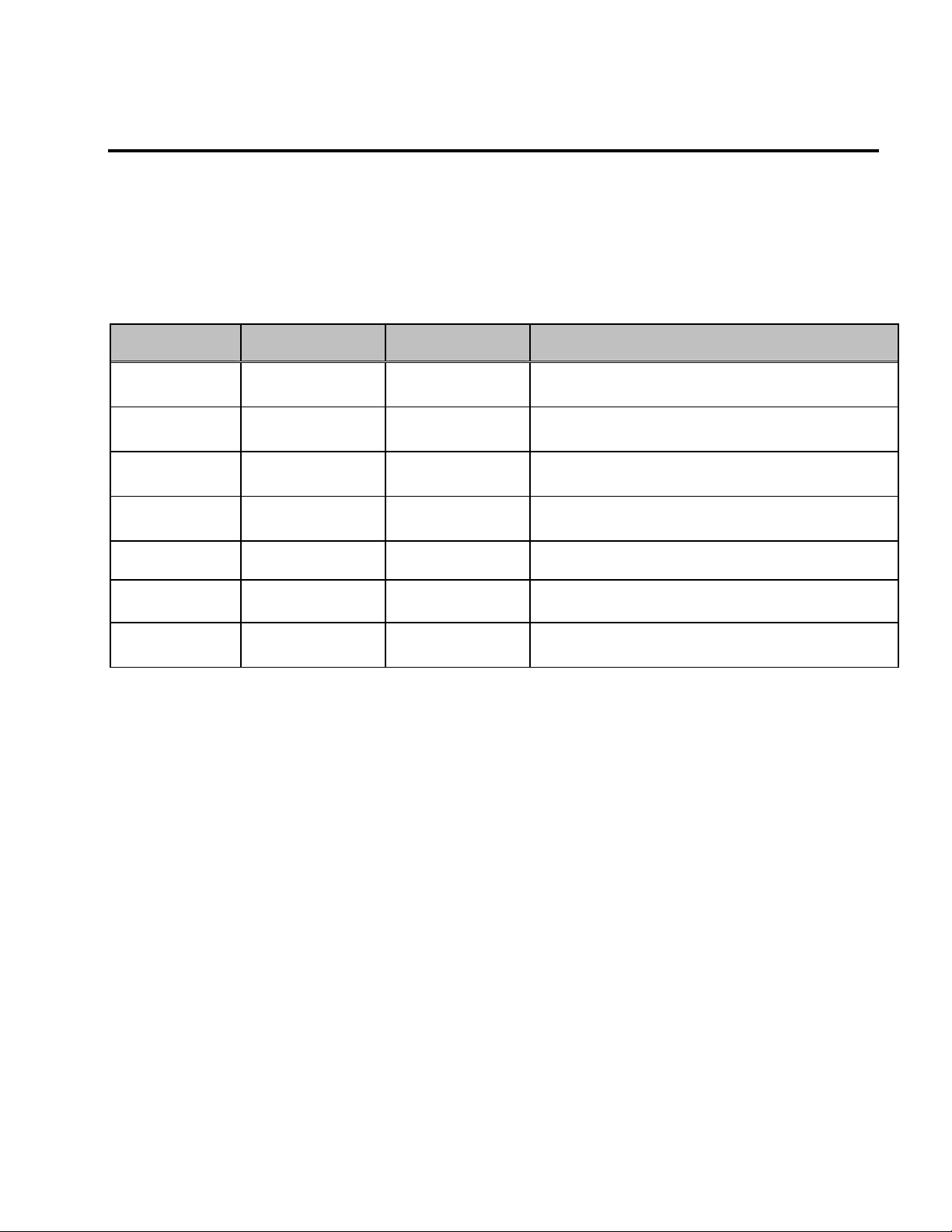
2.4 Operation Method
The ACtionMaster has several operation methods as shown below.
Operation Method Function Function Setting
Operation using Keypad Run/Stop command and frequency are set only through the
keypad.
Operation using
Control Terminals
Operation using both
Keypad and Control
Terminals
Operation using
Option Boards
Closing FX or RX terminal performs Run/Stop.
Frequency reference is set through V1 or I or V1+I terminal.
Run/Stop is performed by the keypad.
Frequency reference is set through the V1 or I or V1+I
terminal.
Closing FX or RX terminal performs Run/Stop.
Frequency reference is set through the keypad.
Operation using option board.
The ACtionMaster has five option boards and three sub-
boards.
Option Boards: RS485, Device-Net, F-Net, ProfiBus and
ModBus
Sub-Boards: Sub-A Board, Sub-B Board, Sub-C Board and
Sub-D Board.
DRV 03: Keypad
DRV 04: Keypad-1 or -2
DRV 03: Fx/Rx-1 or -2
DRV 04: V1 or I or V1+I
DRV 03: Keypad-1 or -2
DRV 04: V1 or I or V1+I
DRV 03: Fx/Rx-1 or -2
DRV 04: Keypad-1 or -2
Please refer to ‘Chapter 7 Options’ for more
information.
2-10
Page 39

Notes:
Chapter 2 - Operation
2-11
Page 40

Page 41

CHAPTER 3 - QUICK-START PROCEDURES
These Quick-Start Up instructions are for those applications where:
The user wants to get the ACtionMaster inverter started quickly
The factory-preset values are suitable for the user application
The factory-preset values are shown on the ‘Chapter 4 - Parameter List’. The ACtionMaster inverter is configured to
operate a motor at 60Hz (base frequency). If the application requires coordinated control with other controllers, it is
recommended the user become familiar with all parameters and features of the inverter before applying AC power.
1. Mounting the inverter (mount the inverter as described in ‘1.3 Mounting’)
Install in a clean, dry location
Allow a sufficient clearance around top and sides of inverter
The ambient temperature should not exceed 40°C (104°F)
If two or more inverters are installed in an enclosure, add additional cooling
2. Wiring the inverter (connect wiring as described in ‘1.7 Power Terminals’)
AC power should be turned OFF
Verify the AC power matches the nameplate voltage
Remove the screw on the bottom front cover of the inverter for terminal board access (For terminal board access
on 15~ 30HP inverters you must disconnect the keypad cable from the inverter and fully removed the cover)
3-1
Page 42

Chapter 3 - Quick-Start Procedures
,
3.1 Operation using Keypad
1. Apply AC power.
2. LCD: Press [▲
7-Seg: Rotate the encoder knob until ‘03’ is
displayed.
3. LCD: Press [PROG] key.
7-Seg: Press[PROG/ENT] key.
4. LCD: Press [▼] key one time.
7-Seg: Rotate the encoder knob left.
5. LCD: Press [PROG] key.
7-Seg: Press [PROG/ENT] key.
6. Press [PROG/ENT] key.
7. LCD: Press [PROG] key.
7-Seg: Press [PROG/ENT] key.
8. LCD: Press [SHIFT/ESC] key and press [▲
key to increase the command frequency.
7-Seg: Rotate the encoder knob right to change
the command frequency.
by pressing the
9. LCD: Press [ENT] key to save the data.
7-Seg: Press [PROG/ENT] key to save the data.
10. LCD: Press [FWD] or [REV] key to start motor.
7-Seg: Press [RUN] key to start motor.
11. Press [STOP/RESET] key to stop motor.
] key three times.
]
The changing digit moves
[SHIFT/ESC] key.
LCD Display
DRV►T/K 0.0 A
00 STP 0.00Hz
DRV► Drive mode
03 Fx/Rx-1
DRV► Drive mode
03 Fx/Rx-1
DRV► Drive mode
03 Keypad
DRV► Drive mode
03 Keypad
DRV►K/K 0.0 A
00 STP 0.00Hz
DRV
► Cmd. freq
00 0.00Hz
DRV
► Cmd. freq
00 60.00Hz
DRV►K/K 0.0 A
00 STP 60.00Hz
The STOP/RESET LED starts blinking.
The FWD or REV LED starts blinking.
7-Segment Display
The DRV LED is ON.
The DRV LED is turned ON.
The PROG/ENT LED turned ON.
The PROG/ENT LED is turned ON.
The PROG/ENT LED is turned ON.
The PROG/ENT LED is turned ON.
The RUN LED starts blinking.
To change the motor running
change DRV 13 to ‘1’.
direction
The STOP/RESET LED starts blinking.
3-2
Page 43

Chapter 3 - Quick-Start Procedures
3.2 Operation using Control Terminals
1. Install a potentiometer on terminals V1, VR, 5G
and connect wiring as shown below.
P1 P2
JOG CM
P3 FX RX NC
CM BX
RST
2. Apply AC power.
3. Confirm that the DRV 03 is set at ‘Fx/Rx-1’.
4. LCD: Press [▲] key to move DRV 04.
7-Seg: Rotate encoder knob until ‘04’ is
displayed.
5. LCD: Press [PROG] key.
7-Seg: Press [PROG/ENT] key.
6. LCD: Press [▲] key and set at ‘V1’.
7-Seg: Rotate encoder knob and set at ‘2’.
7. LCD: Press [ENT] key.
7-Seg: Press [PROG/ENT] key.
8. Press [SHIFT/ESC] key.
9. Set the frequency by rotating the potentiometer.
10. Close the FX or RX contact to run the motor.
11. Open the FX or RX contact to stop the motor.
1 ㏀, 1/2 W
VR VI
I
FM 5G
LCD Display
7-Segment Display
DRV►T/K 0.0 A
00 STP 0.00Hz
DRV► Drive mode
03 Fx/Rx-1
DRV► Freq mode
04 Keypad-1
DRV► Freq mode
04 Keypad-1
DRV► Freq mode
04 V1
DRV► Freq mode
04 V1
DRV►T/V 0.0 A
00 STP 0.00Hz
DRV►T/V 0.0 A
00 STP 60.00Hz
The FWD or REV LED starts blinking. The RUN LED starts blinking.
The STOP/RESET LED starts blinking.
The DRV LED is ON.
The PROG/ENT LED is turned ON.
The PROG/ENT LED is turned ON.
The PROG/ENT LED is turned OFF.
The STOP/RESET LED starts blinking.
3-3
Page 44

Chapter 3 - Quick-Start Procedures
,
3.3 Operation using Keypad and Control Terminals
3.3.1 Frequency set by External Source and Run/Stop by Keypad
1. Install a potentiometer on terminals V1, VR, 5G and connect wiring as shown below left.
When a ‘4 to 20mA’ current source is used as the frequency reference, use terminals I and 5G as shown below right.
DRV 04 must be set at V1.
1 ㏀, 1/2 W
P1 P2
JOG CM
P3 FX RX NC
CM BX
RST
VR VI
I
FM 5G
2. Apply AC power.
3. LCD: Press [▲] key to move DRV 03.
7-Seg: Rotate encoder knob until ‘03’ is
displayed.
4. LCD: Press [PROG] key.
7-Seg: Press [PROG/ENT] key.
5. LCD: Press [▲] key one time.
7-Seg: Rotate encoder knob and set at ‘0’.
6. LCD: Press [ENT] key.
7-Seg: Press [PROG/ENT] key.
7. Confirm that the DRV 04 is set at ‘V1’.
8. Press [SHIFT/ESC] key.
Set the frequency by rotating the potentiometer.
9. LCD: Press [FWD] or [REV] key.
7-Seg: Press [RUN] key.
DRV►T/K 0.0 A
00 STP 0.00Hz
DRV► Drive mode
03 Fx/Rx-1
DRV► Drive mode
03 Fx/Rx-1
DRV► Drive mode
03 Keypad
DRV► Drive mode
03 Keypad
DRV► Freq mode
04 V1
DRV►T/V 0.0 A
00 STP 60.00Hz
The FWD or REV LED starts blinking.
DRV 04 must be set at I.
P1 P2
P3 FX RX NC
JOG CM
CM BX
VR VI
I
RST
4 to 20mA signal
FM 5G
The DRV LED is ON.
The PROG/ENT LED is turned ON.
The PROG/ENT LED is turned ON.
The PROG/ENT LED is turned OFF.
The PROG/ENT LED is turned ON.
The RUN LED starts blinking.
To change the motor running
direction
change DRV 13 to ‘1’.
3-4
Page 45

3.3.2 Frequency set by Keypad and Run/Stop by External Source.
1. Connect wiring as shown below.
P1 P2
JOG CM
P3 FX RX NC
CM BX
RST
VR VI
I
FM 5G
2. Apply AC power.
3. Confirm that the DRV 03 is set at ‘Fx/Rx-1’.
4. Confirm that the DRV 04 is set at
‘Keypad-1’.
5. Press [SHIFT/ESC] key.
6. LCD: Press [PROG] key.
7-Seg: Press [PROG/ENT] key.
7. LCD: Set the frequency using [SHIFT/ESC] and
[▲] key.
7-Seg: Set the frequency by rotating the encoder
knob.
8. LCD: Press [ENT] key to save the data.
7-Seg: Press [PROG/ENT] key to save the data.
9. Close the FX or RX contact to run the motor.
10. Open the FX or RX contact to stop the motor.
DRV►T/K 0.0 A
00 STP 0.00Hz
DRV► Drive mode
03 Fx/Rx-1
DRV► Freq mode
04 Keypad-1
DRV►T/K 0.0 A
00 STP 0.00Hz
DRV
► Cmd. freq
00 0.00Hz
DRV
► Cmd. freq
00 60.00Hz
DRV►T/V 0.0 A
00 STP 60.00Hz
The FWD or REV LED starts blinking. The RUN LED starts blinking.
The STOP/RESET LED starts blinking. The STOP/RESET LED starts blinking.
LCD Display
Chapter 3 - Quick-Start Procedures
7-Segment Display
The DRV LED is ON.
The PROG/ENT LED is turned ON.
The PROG/ENT LED is turned ON.
3-5
Page 46

Page 47

CHAPTER 4 - VARIOUS FUNCTION SETTING & DESCRIPTION
4.1 Function Setting
4.1.1 Basic function parameter setting
It is the basic function setting. All settings are factory defaults unless users make change. It is recommended to use factory
setting value unless the parameter change is necessary.
1) Common parameter setting
The following table shows common parameter setting that should be checked before use but making change does not
affect inverter control type.
Parameter Name Code Description
Rated Motor
Selection
Parameters related to
motor
Drive Mode DRV-3 Operation via Keypad, Fx/Rx-1, Fx/Rx-2 setting enable
Frequency
or
Torque Mode
Accel/Decel time
setting
2) V/f control
FU2-30
FU2-31 ~ 36
DRV-4
DRV-1, DRV-2 Setting Accel/Decel time enable
Select motor and voltage rating suitable to the desired
inverter
Basic parameter value setting when selecting the motor
rating.
Note) If there is any discrepancy between parameter
preset value and the actual motor parameter value,
change the parameter value according to the actual
motor.
Frequency/Torque setting parameter
It automatically changes to torque mode when FU2 39[Control mode] is set to Sensorless_T, Vector_TRQ
FU2-39 [Control mode] is set to 0 (V/F) as factory setting. Operation via V/F control can be performed after
common parameter settings are done and the followings are set.
Parameter Name Code Description
Starting freq. FU1-22 Setting frequency to start the motor
Torque boost FU1-26
Torque boost value in
FWD/REV
FU1-27, FU1-28
Manual or Auto torque boost settable in this parameter
If FU1-26 [torque boost] is set to manual, user sets the
desired value and the direction in code FU1-27 and 28.
Page 48

Chapter 4 – Function Settings
3) V/F + PG control
If FU2-39 [control mode] is set to V/F with PG (encoder) feedback using SUB-B or SUB-D boards, the control type is
automatically changed to V/F + PG. The following parameters should be set accordingly to enable PG feedback using SUBB or SUB-D boards.
Parameter Name Code Description
Usage of Pulse Input
Signal
Pulse Input Signal
Selection
Encoder Pulse
Number
P-Gain for ‘Sub-B’
I-Gain for ‘Sub-B’
Slip Frequency for
‘Sub-B’ Board
EXT-12
EXT-15
EXT-16 Defines the number of encoders of the motor.
EXT-22, EXT-23 PI gains for PI controller during PG operation
EXT-24 Setting as a percent of FU2-32 [Rated Motor Slip]
Defines the use of pulse input signal with SUB-B or SUBD mounted. This parameter should be set to 1 {Feedback}.
Three types of input signal settable;
(A+B), A, -(A+B)
4) Slip compensation
operation is done via Slip compensation if FU2-39 is set to 1 {Slip compen}. This control keeps motor speed constant
regardless of load change.
5) Auto-tuning of motor constant
This parameter enables auto-tuning of the motor constants. If set to 1 {All mode}, tuning type varies according to what
control mode is set in [FU2-39]. Auto-tuning can be done in two ways – one is motor non-rotation mode, the other is motor
rotation mode.
①①①① Auto-tuning by non-rotation mode: Rs+Lsigma
②②②② Auto-tuning by rotation mode : All, Enc Test, Tr
Before performing Auto-tuning, set motor rating, motor parameter in common setting and select the desired
control mode in FU2-39 [control mode selection]. However, when auto-tuning parameters related to encoder, detail
functions settings of vector control should be pre-defined. If Enc Test, Tr and control mode are set to vector control,
Sub-B or Sub-D board should be mounted.
Parameter Name Code Description
Auto-tuning FU2-40
Parameter value
display
FU2-34,
FU2-41 ~ 44
No, All, Rs+Lsigma, Enc Test, Tr
Tuned value monitoring
(no-load current, stator/rotor resistance, leakage
inductance, rotor filter time constant)
4-2
Page 49

Chapter 4 – Function Settings
FU2-40 Description
No Motor constants calculation disabled
All constants can be measured in this code but different constants are tuned
according to control mode type;
For V/F, Slip compen , Sensorless_S, Sensorless_T:
(No-load current, stator resistance, leakage inductance, stator inductance
All
available)
Note) Only no-load current can be calculated during V/F and Slip compensation.
For Vector_SPD, Vector_T:
No-load current, stator resistance, leakage inductance, stator inductance,
encoder test, rotor filter time constant
Rs+Lsigma Calculate stator resistance, leakage inductance
Enc Test Calculate the encoder status
Tr Calculate Rotor filter time constant
6) Sensorless vector control
Set FU2-39 to 2 {Sensorless_S} or 3 {Sensorless_T} to enable Sensorless vector control. It is strongly recommended to
perform Auto-tuning for Sensorless before starting Sensorless control in order to maximize performance. Two types of
Sensorless vector control are available; Sensorless_S or Sensorless_T.
Parameter Name Code Description
Control mode selection FU2-39 Select Sensorless_S or Sensorless_T
P, I gain for sensorless
control
FU2-45, FU2-46 Setting gain for Sensorless_S control
Starting freq FU1-22 Starting freq of the motor
7) Vector control
Set FU2-39 to 4 {Vector_SPD} or 5{Vector_TRQ} to enable Vector control. Encoder should be installed to the motor with
Sub-B or Sub-D boards in the inverter to start this control.
Parameter Name Code Description
Usage of Pulse Input
Signal
Pulse Input Signal
Selection
EXT-12
EXT-15
Defines the method of pulse input with SUB-B or SUB-D
boards mounted. Vector control setting is valid only after
this parameter is set to 1 {Feed-back}.
3 types of pulse input : (A+B), A, -(A+B)
Encoder Pulse Number EXT-16 Enter the pulse number of encoder in the motor.
4-3
Page 50

Chapter 4 – Function Settings
Before selecting Vector control mode, encoder setting should be done as indicated above. If the parameter value of actual
motor is set in common setting, execute Auto-tuning before selecting vector control mode.
Parameter Name Code Description
Control Mode Selection FU2-39 Select Vector_SPD or Vector_TRQ
Forward/ Reverse
Torque Limit
P-Gain/ I-Gain for
(Sensored) Vector_SPD
Speed Limit setting
Zero Speed Detection
Level/ Bandwidth
Torque Detection
Level/Bandwidth
EXT-27, EXT-28
EXT-25, EXT-26 Setting P/I Gain for Vector_SPD control
EXT-50, EXT-51
EXT-52, EXT-53
EXT-54, EXT-55
EXT-56, EXT-57 Detect certain level/bandwidth of Torque
Setting the FWD/REV limit to the torque current
Setting speed limit for Vector_TRQ
Setting on/off of Multi-function output terminal relay when
the motor speed reaches to 0.
4.1.2 Advanced function 1 setting
SV-ACtionMaster inverter features advanced function parameters to maximize efficiency and performance of the motor. It is
recommended to use as factory setting unless parameter value change is necessary.
1) V/F control
Parameter Name Code Description
Use it according to load characteristics. If User V/F is
V/F Pattern FU1-29
selected, User can select the optimum output V/F
characteristic for the aplication and load characteristics in
[FU1-30]~[FU1-37]
Dwell operation
Frequency jump
S-shaped curve
Accel/Decel pattern
FU2-07
FU2-08
FU2-10
FU2-11~16
FU2-17/ FU2-18
Used to output torque in an intended direction. Inverter
stops acceleration for the preset [FU2-08] Dwell time
while running at Dwell frequency [FU2-07] and starts
acceleration at commanded frequency. Setting [FU2-08]
Dwell time to 0 disable the Dwell operation.
When it is desired to avoid resonance attributable to the
natural frequency of a mechanical system, these
parameters allow resonant frequencis to be jumped. Up to
three areas can be set, with the jump frequencies set to
either the top or bottom point of each area. To enable the
function, set [FU2-10] to ‘Yes’ and set the value in [FU211]~[ FU2-16].
This pattern has an effect on the prevention of cargo
collapse on conveyor etc and reduction in an acceleration/
deceleration shock.
4-4
Page 51

Chapter 4 – Function Settings
2) Sensorless vector control
Related parameters for starting during Sensorless vector control when FU2-39 [Control Mode Selection] is set to 2
{Sensorless_S}.
Status Code Description
FU1-14 Setting pre-excitation time
When starting
I/O12~14
EXT2~4
Multi-function input terminal P1- P6 define
3) Vector control [Vector_SPD, Vector_TRQ]
Related parameters for starting/ running/ stopping during Vector control when FU2-39 [Control Mode Selection] is set to 4
{Vector_SPD}.
Status Code Description
FU1-14 Setting pre-excitation time
When starting
I/O12~14
EXT2~4
Multi-function input terminal P1- P6 define
Pre-excitation current FU1-16 Setting the Pre-excitation current
FU1-15 Setting hold time at a stop
When stopping
FU1-7 Stopping method selection
This parameter can limit the over-speeding (motor running above limit level) of the motor when FU2-39[Control mode] is set
to 5 {Vector_TRQ}.
Parameter Name Code Description
Speed limit level
/ bias / gain
EXT-50
~
EXT-53
Function to limit the speed and change reference torque
value according to speed
4) Parameters to view motor and inverter status
Parameter Name Code Description
Output current/
motor speed
DRV 8 ~ 9 Display output current and motor rpm
DC link voltage DRV 10 Display DC link voltage
User display selection
(Voltage and watt)
Reference/ Feedback
frequency display
DRV11
FU2-73
Either output voltage or power selected in FU2-73 is
displayed in DRV11.
DRV15 Display Reference/ Feedback frequency display
Fault display DRV12 Display the current inverter fault
4-5
Page 52

Chapter 4 – Function Settings
5) Parameter initialize
Parameter Name Code Description
Software version FU2-79 Display the inverter software version
Parameter
Read/Write/Initialize/Write
protection
FU2-91
FU2-92
FU2-93
FU2-94
[FU2-91], [FU2-92]: Copying parameters from other
inverter enabled
[FU2-93]: Initializing parameters to factory setting values
[FU2-94] : Parameter write disabled
6) Protection & fault detection level setting
Parameter Name Code Description
Electronic thermal
Overload alarm and trip
FU1-50
FU1-51
FU1-52
FU1-53
FU1-54, FU1-55
FU1-56, FU1-57
FU1-58
Protection of the motor from overheating without the use of
external thermal relay. Refer to parameter descriptions for
more detail.
Warning alarm outputs and displays the trip message when
overcurrent above the threshold value keeps on.
Set the output current level at which the output freq will be
Stall prevention FU1-59, FU1-60
adjusted to prevent the motor from stoping due to overcurrent etc. it activates during accel/ constant speed/ decel
to prevent the motor stall.
7) Starting / Accel/ Decel / Stopping pattern setting
Parameter Name Code Description
5 types of Accel/ Decel pattern: ‘Linear’, ‘S-curve’, ’U-
Accel/Decel pattern
FU1-05
FU1-06
curve’, ’Minimum’, ‘Optimum’ settable according to
appplication and load characteristic. If ‘S-curve’ is selected,
the desired value of [FU2-17], [FU2-18] is settable.
3 types of stopping method ‘Decel’, ‘DC-brake’, ‘Free-run’
Stopping method FU1-07
selectable. If ‘DC-brake’ is selected, the desired value of
[FU1-8]~ [FU1-11] is settable.
The motor accelerates after the preset [FU1-12] for the
Starting DC Injection
Braking Voltage/ Time
FU1-12
FU1-13
preset [FU1-13] is applied. Starting DC injection braking is
inactive when the value is set to 0 in control mode other
than V/F and Slip compensation.
Limits the active frequency. Inverter operates at the freq
range between upper freq limit [FU1-25] and bottom freq
limit [FU1-24] and higher/ lower freq value is entered, it is
automatically replaced by limit value. Setting range: [FU1-
Frequency Limit selection
FU1-23
Fu1-24
FU1-25
20] Maximum freq to [FU1-21] Base freq.
Dynamic braking
FU2-75
FU2-76
Select the DB resistor mode when the regenerative load. Is
connected. Refer to DBU manual for more details.
4-6
Page 53

Chapter 4 – Function Settings
8) Operation-starting method
Parameter Name Code Description
Motor starting method:
Starting method
FU2-20
FU2-21
FU2-26
FU2-27
[FU2-20] : Power-on run,
[FU2-21] Restart after Fault Reset,
[FU2-26] Number of Auto Restart Attempt
[FU2-27] Delay Time Before Auto Restart
See parameter description for more.
Speed Search Selection
FU2-22
FU2-23
FU2-24
FU2-25
Speed search function is available during Accel, trip,
instant power failure, restart after fault reset and auto
restart. See parameter description for more.
4.1.3 Advanced function 2 setting
1) PID operation
The inverter can be used to exercise process control, e.g. flow rate, air volume or pressure via PID feedback control.
Parameter Name Code Description
PID control setting FU2-41~ FU2-60 Setting parameters for PID control
2) Jog and Multi-speed operation
Parameter Name Code Description
Multi function input
terminal setting
Filter time constant for
input terminal
Speed reference value
Accel/Decel time
setting for each step
Jog freq. I/O-20
I/O-12 ~14
EXT2 ~ 4
If I/O-12 ~14 are set to Speed-H, Speed-M, Speed-L,
multi- speed operation up to speed 7 enable..
I/O-17 Effective for eliminating noise in the freq. setting circuit
DRV-05 ~ 7
I/O-21 ~ I/O-24
Setting speed reference value for each step
I/O-25 ~ 38 Setting Accel/Decel time for each step
Setting jog freq for jog operation
Speed-H Speed-M Speed-L JOG Speed Signal Applied speed value
0 0 0 0 Speed 0 DRV-00
X x X 1 Jog freq. I/O-20
0 0 1 0 Speed –1 DRV-05
0 1 0 0 Speed –2 DRV-06
0 1 1 0 Speed –3 DRV-07
1 0 0 0 Speed –4 I/O-21
1 0 1 0 Speed –5 I/O-22
1 1 0 0 Speed –6 I/O-23
1 1 1 0 Speed –7 I/O-24
4-7
Page 54

Chapter 4 – Function Settings
3) Auto sequence operation
If I/O-50 [Auto (Sequence) Operation selection] is set to 1 {Auto-A} or 2 {Auto-B}, up to 5 sequences can be set with max of
8 steps (speed) in each sequence. Therefore, max 40 operating steps can be made. Two different types of auto sequence
(A, B) operation are available.
Parameter Name Code Description
Auto operation setting I/O-50 ~ 84 Set 8 steps and 5 sequences (Max)
-
nd
motor operation
4) 2
nd
2
function setting is required to run the two motors by one inverter by exchange. If the terminal defined for 2nd function
signal input is turned ON, 2
nd
motor operation is valid.
Parameter Name Code Description
Multi-function input
terminals setting
Parameter setting for
nd
2
motor operation
I/O-12 ~14
EXT2 ~ 4
FU2-81 ~ FU2-90
2nd motor operation is available with Multi-function input
terminals P1 ~ P3 or P4 ~ 6 set to 7 {2
Setting parameters necessary to operate 2
as base freq., Accel/Decl time, Stall.
5) Energy-saving operation
FU1-39 [
Energy Save Level] tunes the inverter output voltage to minimize the inverter output voltage during during constant
speed operation. Appropriate for energy-saving applications such as fan, pump and HVAC.
nd
Func}.
nd
motor such
4-8
Page 55

4.2 Operation Example
Operation
V/F Control + Analog Voltage Input (V1) + Operation via Terminal (FX/RX)
Example (1)
[Operation condition]
-. Control mode : V/F control
-. Frequency command : 50[Hz] analog input via V1 terminal
-. Accel/Decel time : Accel – 15 [Sec], Decel – 25 [Sec]
-. Drive mode: Run/Stop via FX/RX terminal
[Wiring]
input
3P
AC
R
S
T
G
B1 B2
Chapter 4 – Operation Examples
U
V
W
IM
S/W
Potentiometer
1[kohm],1/2W
FX
RX
BX
RST
JOG
P1
P2
P3
CM
VR
V1
5G
FM
5G
30A
30C
30B
AXA
AXC
Step Parameter setting Code Description
1 Control Mode Selection FU2-39 Set it to 0 {V/F}
2 Drive Mode DRV-3 Set it to Fx/Rx-1.
3 Frequency Mode DRV-4 set V1 Analog input value in frequency mode
4
5 Accel/Decel time
50[Hz] freq command
setting
DRV-0 set freq command 50[Hz] via V1(potentiometer)
DRV-2
DRV-3
Set Accel time to 15 [Sec] in DRV-2
Set Decel time to 25 [Sec] in DRV-3
Motor starts to rotate in Forward direction at 50Hz with Accel time 15 [sec]
6 Terminal FX
when FX terminal is turned ON.
Motor decelerates to stop with Decel time 25[sec] when FX terminal is
turned OFF.
When RX terminal is turned ON motor starts to rotate in Reverse direction
7 Terminal RX
at 50[Hz] with Accel time 15 [Hz]. When it is OFF, motor decelerates to
stop with Decel time 25 [Sec].
Page 56

Chapter 4 - Operation Examples
Operation
example (2)
(V/F + PG) Control + operation (Run/Stop) via Keypad
[Operation condition]
-. Control mode: V/F + PG control
-. Frequency command: 50[Hz] Digital input via Keypad
-. Accel time : 15[sec], Decel time : 25 [sec]
-. Drive mode : Run/Stop via Keypad
-. Wiring block diagram when an Open Collector- type encoder is used.
[Wiring]
B1 B2
3P
AC
Input
LC-200
MODE PROG ENT
STOP
REV
RESET
SHIFT
ESC
FWD
R
S
T
G
FX
RX
BX
RST
JOG
P1
P2
P3
CM
VR
V1
5G
Keypad
connector
U
V
IM
W
E
A+
A-
B+
B-
Power
Supply
12V-15V DC
Sub-B
Encoder
AOC
BOC
FBA
FBB
GND
GND
+5V
+5V
VCC
VCC
Step Parameter setting Code Description
1 Control Mode Selection FU2-39 Set it to 0 {V/F}.
2 Drive mode DRV-3 Set it to 0 {KeyPad}.
3 Frequency Mode DRV-4 Set it to 0 {KeyPad-1}.
4
5 Accel/Decel time setting
6 Sub-B board setting
Digital Command
Frequency setting
DRV-0 Press PROG key on the keypad to set 50 Hz
DRV-2 DRV-3 Accel time: set DRV-2 to 15[sec]
Decel time: set DRV-3 to 25[sec]
EXT-12
EXT-15
EXT-16
Set EXT-12 [Usage of Pulse Input Signal] to 1 {Feed-back} and set EXT15 and EXT-16 after checking encoder rating on the nameplate.
Motor runs at 50[Hz] in forward direction with Accel time 15[sec] by PG
7 FWD Operation
control when pressing FWD key on the keypad. Motor decelerates to
stop with Decel time 25[sec] when pressing Stop key.
Motor runs at 50[Hz] in reverse direction with Accel time 15[sec] by PG
8 REV Operation
control when pressing REV key on the keypad. Motor decelerates to
stop with Decel time 25[sec] when pressing Stop key.
4-10
Page 57

Operation
2nd motor operation
Example (3)
[Operation condition]
-. Control mode: V/F control
st
motor + 2nd motor Operation by exchange using [2nd Func] (Values can be set differently)
-. 1
-. Frequency command : Using Multi-speed
st
1
nd
2
FX
RX
BX
1st / 2nd
motor
select
CM
st
motor --- Accel time: 15[Sec], Decel time: 25 [Sec]
nd
motor --- Accel time: 30[Sec], Decel time: 40 [Sec]
3P
AC
input
-. Accel/Decel time : 1
2
-. Drive mode : Run/Stop via FX/RX
[Wiring]
Chapter 4 - Operation Examples
motor --- Apply 50[Hz] as main speed
motor --- Apply 20[Hz] with P1 terminal set as multi-speed operation
B1 B2
R
S
T
G
FX
RX
BX
RST
JOG
P1
P2
P3
CM
VR
V1
5G
FM
5G
30A
30C
30B
AXA
AXC
U
V
W
1st /2nd motor
IM 1st motor
IM
Switch-over
2nd
motor
Step Parameter setting Code Description
1 Control Mode Selection FU2-39 Set it to 0 {V/F}.
2 Drive mode DRV-3 Set it to Fx/Rx-1.
3 Frequency Mode setting DRV-4
Set it to 0 {keypad-1}.
(setting 1
st
motor freq)
4 Multi-function input terminal P2 I/O-13 Set P2 to 2nd Func.
5 Multi-function input terminal P1 I/O-12
Set P1 to Speed-L).
(setting 2
nd
motor freq)
6 Freq setting for 1st motor DRV-0 Set it to 50[Hz].
7 Accel/Decel time setting for 1st motor
DRV-1,
DRV-2
Set Accel/Decel time to 15[sec]/25[sec].
8 Freq setting for 2nd motor DRV-5 Set it to 10[Hz].
9 Accel/Decel time setting for 2nd motor FU2-81/82 Set Accel/Decel time to 30[sec]/50[sec].
10 1st motor operation
11 2nd motor operation
- Set it as main motor by turning P1, P2, output relay OFF.
- Run the motor in FWD/REV direction using FX/RX terminal.
nd
motor parameters by turning terminal P2 ON.
- Set 2
- Change the freq setting to 20[Hz] by turning terminal P1 ON.
- Change 2
nd
motor terminal by turning output relay ON.
-Run the motor in FWD/REV direction by terminal FX/RX.
4-11
Page 58

Chapter 4 - Operation Examples
N
Operation
Example (4)
Sensorless_S Control + Multi-speed operation + Analog output (FM)
[Operation condition]
-. Control mode : Sensorless Speed control
-. Frequency command : Multi-function input from
SUB-A and 8 step speed operation
(Multi-speed 7 + jog freq 1)
-. Accel time : 5 [Sec], Decel time: 5 [Sec]
-. Drive mode : Run/Stop and speed output via terminal FX/RX
[Wiring]
Output freq [Hz]
SPD 0 SPD 1 SPD 2 SPD 3 SPD 4 SPD 5 SPD 6 SPD 7 JOG
JOG
FX
RX
P4
P5
P6
ON ON ON ON
ON
ON
Multi-speed freq setting range
DRV-00 Speed 0
DRV-05 Speed 1
DRV-06 Speed 2
DRV-07 Speed 3
ON
ON
ON
I/O-20 Speed 4
I/O-21 Speed 5
I/O-22 Speed 6
I/O-23 Speed 7
B1 B2
R
S
T
G
S/W
O
FX
RX
BX
RST
JOG
P1
P2
P3
CM
FM
5G
30A
30C
30B
AXA
AXC
CN5
U
V
W
FM
Sub - A
IM
Output
freq meter
0 -10 V,
Pulse
S/W
P4
P5
P6
CM
Step Parameter setting Code Description
1 Control Mode Selection FU2-39 Set it to Sensorless_S.
2 Drive mode DRV-3 Set it to FX/RX-1.
3 Multi-function input EXT-2 ~ 4 Set P3, P4, P5 to Speed-L, Speed-M, Speed-H.
FM
4
(Frequency Meter) Output
I/O-40 Set it to Frequency output
Selection
5 FM Output Adjustment I/O-41
Output V = 10V x output freq x output gain (ex100%) /
( Max freq x 100 )
Motor runs in forward direction at the set freq via P3, 4, 5 if Fx terminal is
6 Terminal FX
ON.
Motor decelerates to stop with Decel time 5 [sec] if FX terminal is OFF.
Motor runs in reverse direction at the set freq via P3, 4, 5 if RX terminal is
7 Terminal RX
ON.
Motor decelerates to stop with Decel time 5 [sec] if RX terminal is OFF.
4-12
Page 59

Chapter 4 - Operation Examples
Operation
Vector_SPD Control
Example (5)
[Operation condition]
-. Control Mode : Vector_SPD Control, -. Encoder specification : Pulse number (1024), Line Drive type
-. Freq command : set it 55[Hz] via KPD-1
-. Accel/Decel time : Accel – 15 [sec], Decel – 25 [sec], -. Drive mode : Run/Stop via terminal FX/RX
[Wiring]
B1 B2
3P
AC
Input
MODE PROG ENT
REV
LC-200
RESET
R
S
T
G
FX
RX
SHIFT
ESC
STOP
FWD
BX
RST
JOG
P1
P2
P3
CM
VR
V1
5G
Keypad
connector
Sub-B
U
V
W
Encoder
AOC
BOC
A+
A-
B+
B-
FBA
FBB
GND
GND
+5V
+5V
VCC
VCC
IM
E
Step Parameter setting Code Description
1 Motor related setting
FU2-30 ~ FU2-
36
EXT-12
2 Encoder related setting
EXT-15
EXT-16
3 Control Mode Selection Fu2-39
4 Auto-tuning FU2-40
5 Keypad input setting
6 Accel/Decel time setting
DRV-4
DRV-0
DRV-1
DRV-2
Set motor capacity, pole number, rated voltage/ current/slip and
efficiency.
Set EXT-12 to Feed-back, EXT-1 to A+B
Set EXT-16 to 1024
Encoder related setting should be done before setting control mode to
Vector_SPD.
Auto-tuning starts when set to ALL. Read the encode rmanual carefully
to clear the error if the messages ” Enc Err”, “Enc Rev” are displayed.
Set DRV-4 to KPD-1 and press the Prog key to set 55 [Hz] in Drv-0.
Accel time: set 15[Sec]
Decel time: set 25[Sec]
7 Drive mode DRV-3 Set it to FX/RX-1.
Motor runs with Accel time 15 [Sec] at 55 [Hz] if FX/RX terminal is
8 FX/RX terminal
turned ON.
Motor decelerates to stop with Decel time 25 [Sec] if FX/RX terminal is
turned OFF.
4-13
Page 60

Chapter 4 - Operation Examples
Notes:
4-14
Page 61

CHAPTER 5 - PARAMETER LIST
5.1 Drive Group [DRV]
Code Description
Command Frequency or
Command Torque
(Output Frequency/
DRV-0010
DRV-01 Acceleration Time
DRV-02 Deceleration Time
DRV-03
DRV-04
DRV-05 Step Frequency 1
DRV-06 Step Frequency 2
DRV-07 Step Frequency 3
DRV-08 Output Current
DRV-09 Motor Speed
DRV-10 DC link Voltage
DRV-11 User Display Selection
DRV-12 Fault Display
DRV-13 Motor Direction Set
DRV-14
DRV-1511
DRV-16 Speed Unit Selection
Torque during motor run,
Reference Frequency/
Torque during motor
stop)
Output Current (LCD)
Drive Mode
(Run/Stop Method)
Frequency Mode or
Torque Mode
(Frequency/Torque
setting Method)
Target/Output Frequency
Display
Reference/Feedback
Frequency Display
Torque mode
Step freq-1
Step freq-2
Step freq-3
DC link Vtg
displayed in
Keypad Display Setting Range
LCD 7-Segment LCD 7-Segment
Cmd. freq
or
Cmd. Trq
F or r
(DRV-13)
Acc. time
Dec. time
Drive mode
Freq mode
or
Current
Speed
User disp
Fault
Not
LCD keypad
TAR
OUT
REF
FBK
Hz/Rpm Disp
Units
0 to FU1-20 (Max. freq) 0.01 0.00 [Hz] Yes 6-2
01 0 to 6000 0.1 10.0 [sec] Yes 6-2
02 0 to 6000 0.1 20.0 [sec] Yes 6-2
Keypad 0
03
04
05 10.00 [Hz]
06 20.00 [Hz]
07
08 The Load Current in RMS - [A] - 6-2
09 The Motor Speed in rpm - [rpm] - 6-2
10 The DC Link Voltage inside inverter - [V] - 6-2
11 Selected in FU2-73 (User Disp) - - - 6-2
12 - - -
13 Not available
14 - - - 0.00 [Hz] Yes 6-2
15 - - - 0.00 [Hz] Yes 6-2
16 Hz disp 0 - - Yes 6-2
Fx/Rx-1 1
Fx/Rx-2 2
Keypad-1 0
Keypad-2 1
V1 2
I 3
V1+I 4
FU1-22 to FU1-20
(Starting freq to Max. freq)
0 [Forward]
1 [reverse]
Factory
Default
- Fx/Rx-1 No 6-2
- Keypad-1 No 6-2
0.01
30.00 [Hz]
None
nOn
- 0 Yes 6-2
Adj.
During
Page
Run
Yes 6-2
- 6-2
10
The speed unit is changed to [%] when FU2-39 is set to ‘Sensorless_T’ or ‘Vector_TRQ’.
11
Code DRV-15 appears only when FU2-47 is set to ‘Yes’.
5-1
Page 62

Chapter 5 - Parameter List
Code Description
DRV-20 FU1 Group Selection 20 6-2
DRV-21 FU2 Group Selection 21 6-2
DRV-22 I/O Group Selection 22 6-2
DRV-2312 EXT Group Selection 23
DRV-24 COM Group Selection 24 - 1 Yes 6-2
DRV-25 APP Group Selection
Keypad Display Setting Range
LCD 7-Segment LCD 7-Segment
Not
displayed in
LCD keypad
Rpm disp 1
Not available
25
Units
Press
[PROG/ENT]
key
Factory
Default
- 1 Yes
- 1 Yes 6-2
Adj.
During
Run
Page
6-2
12
Code DRV-23 through DRV-24 appears only when a Sub-Board or an Option Board is installed.
5-2
Page 63

5.2 Function 1 Group [FU1]
Code Description
FU1-00 Jump to Desired Code #
FU1-03 Run Prevention
FU1-05 Acceleration Pattern
FU1-06 Deceleration Pattern
FU1-07 Stop Mode
FU1-0813
FU1-09
FU1-10
FU1-11
FU1-12
FU1-13
FU1-14 Pre-excitation Time
FU1-15 Hold Time
FU1-16 Pre-excitation Current
FU1-20 Maximum Frequency
FU1-21 Base Frequency
FU1-22 Starting Frequency
FU1-23 Frequency Limit selection
FU1-2414 Low Limit Frequency
DC Injection Braking
Frequency
DC Injection Braking
On-delay Time
DC Injection Braking
Voltage
DC Injection Braking
Time
Starting DC Injection
Braking Voltage
Starting DC Injection
Braking Time
Keypad Display Setting Range
LCD 7-Segment LCD 7-Segment
Jump code
Run Prev.
Acc. pattern
Dec. pattern
Stop mode
DcBr freq
DcBlk time
DcBr value
DcBr time
DcSt value
DcSt time
PreExTime
Hold Time
Flux Force
Max freq
Base freq
Start freq
Freq limit
F-limit Lo
Not displayed 1 to 60 Not available 1 1 Yes 6-2
None 0
03
05
06
07
08 FU1-22 to 60 [Hz] 0.01 5.00 [Hz] No
09 0 to 60 [sec] 0.01 0.1 [sec] No
10 0 to 200 [%] 1 50 [%] No
11 0 to 60 [sec] 0.1 1.0 [sec] No
12 0 to 200 [%] 1 50 [%] No
13 0 to 60 [sec] 0.1 0.0 [sec] No
14 0 to 60 [sec] 0.1 1.0 [sec] No 6-2
15 0 to 1000 [ms] 1 1000 [ms] No 6-2
16 100 to 500 [%] 0.1 100.0 [%] No 6-2
20 40 to 400 [Hz] 0.01 60.00 [Hz] No
21 30 to FU1-20 0.01 60.00 [Hz] No
22 0.01 to 60 [Hz] 0.01 0.50 [Hz] No
23
24 FU1-22 to FU1-25 0.01 0.50 [Hz] No
Forward Prev 1
Reverse Prev 2
Linear 0
S-curve 1
U-curve 2
Minimum 3
Optimum 4
Linear 0
S-curve 1
U-curve 2
Minimum 3
Optimum 4
Decel 0
DC-brake 1
Free-run 2
No 0
Yes 1
Chapter 5 - Parameter List
Units
Factory
Default
- None No 6-2
- Linear No 6-2
- Linear No 6-2
- Decel No 6-2
- No No
Adj.
During
Run
Page
6-2
6-2
6-2
6-2
13
Code FU1-08 through FU1-11 appears only when FU1-07 is set to ‘DC-Brake’.
14
Code FU1-24 through FU1-25 appears only when FU1-23 is set to ‘Yes’.
5-3
Page 64

Chapter 5 - Parameter List
Code Description
FU1-25 High Limit Frequency
FU1-26
FU1-27
FU1-28
FU1-29 Volts/Hz Pattern
FU1-3015 User V/F – Frequency 1
FU1-31 User V/F – Voltage 1
FU1-32 User V/F – Frequency 2
FU1-33 User V/F – Voltage 2
FU1-34 User V/F – Frequency 3
FU1-35 User V/F – Voltage 3
FU1-36 User V/F – Frequency 4
FU1-37 User V/F – Voltage 4
FU1-38
FU1-39 Energy Save Level
FU1-50
FU1-5116
FU1-52
FU1-53
FU1-54 Overload Warning Level
FU1-55
FU1-56 Overload Trip Selection
FU1-57 Overload Trip Level
FU1-58 Overload Trip Delay Time
FU1-59
FU1-60 Stall Prevention Level
Manual/Auto Torque
Boost Selection
Torque Boost in Forward
Direction
Torque Boost in Reverse
Direction
Output Voltage
Adjustment
Electronic Thermal
Selection
Electronic Thermal Level
for 1 Minute
Electronic Thermal Level
for Continuous
Electronic Thermal
Characteristic Selection
(Motor Type)
Overload Warning Hold
Time
Stall Prevention Mode
Selection
Keypad Display Setting Range
LCD 7-Segment LCD 7-Segment
F-limit Hi
Torque boost
Fwd boost
Rev boost
V/F pattern
User freq 1
User volt 1
User freq 2
User volt 2
User freq 3
User volt 3
User freq 4
User volt 4
Volt control
Energy save
ETH select
ETH 1 min
ETH cont
Motor type
OL level
OL time
OLT select
OLT level
OLT time
Stall prev.
Stall level
25 FU1-24 to FU1-20 0.01 60.00 [Hz] No
26
27 0 to 15 [%] 0.1 2.0 [%] No
28 0 to 15 [%] 0.1 2.0 [%] No
29
30 0 to FU1-20 0.01 15.00 [Hz] No
31 0 to 100 [%] 1 25 [%] No
32 0 to FU1-20 0.01 30.00 [Hz] No
33 0 to 100 [%] 1 50 [%] No
34 0 to FU1-20 0.01 45.00 [Hz] No
35 0 to 100 [%] 1 75 [%] No
36 0 to FU1-20 0.01 60.00 [Hz] No
37 0 to 100 [%] 1 100 [%] No
38 40 to 110 [%] 0.1 100.0 [%] No 6-2
39 0 to 30 [%] 1 0 [%] Yes 6-2
50
51 FU1-52 to 200 [%] 1 150 [%] Yes
52 50 to FU1-51 1 100 [%] Yes
53
54 30 to 150 [%] 1 150 [%] Yes
55 0 to 30 [sec] 0.1 10.0 [sec] Yes
56
57 30 to 150 [%] 1 180 [%] Yes
58 0 to 60 [sec] 1 60.0 [sec] Yes
59
60 30 to 250 [%] 1 180 [%] No
Manual 0
Auto 1
Linear 0
Square 1
User V/F 2
No 0
Yes 1
Self-cool 0
Forced-cool 1
No 0
Yes 1
000 to 111
(Bit Set)
Units
Factory
Default
- Manual No 6-2
- Linear No 6-2
- No Yes
- Self-cool Yes
- Yes Yes
bit 000 No
Adj.
During
Run
Page
6-2
6-2
6-2
6-2
6-2
6-2
15
Code FU1-30 through FU1-37 appears only when FU1-29 is set to ‘User V/F’.
16
Code FU1-51 through FU1-53 appears only when FU1-50 is set to ‘Yes’.
5-4
Page 65

Chapter 5 - Parameter List
Code Description
FU1-99 Return Code
Keypad Display Setting Range
LCD 7-Segment LCD 7-Segment
Not
displayed
99 Not available
[PROG/ENT]
[SHIFT/ESC]
or
Units
Factory
Default
- - - 6-2
Adj.
During
Run
Page
5-5
Page 66

Chapter 5 - Parameter List
5.3 Function 2 Group [FU2]
Code Description
FU2-00 Jump to desired code #
FU2-01 Previous Fault History 1
FU2-02 Previous Fault History 2
FU2-03 Previous Fault History 3
FU2-04 Previous Fault History 4
FU2-05 Previous Fault History 5
FU2-06 Erase Fault History
FU2-07 Dwell Frequency
FU2-08 Dwell Time
FU2-10
FU2-1117 Jump Frequency 1 Low
FU2-12 Jump Frequency 1 High
FU2-13 Jump Frequency 2 Low
FU2-14 Jump Frequency 2 High
FU2-15 Jump Frequency 3 Low
FU2-16 Jump Frequency 3 High
FU2-17
FU2-18
FU2-19
FU2-20 Power ON Start Selection
FU2-21 Restart after Fault Reset
FU2-22 Speed Search Selection
FU2-23
FU2-24
FU2-25
FU2-26
Frequency Jump
Selection
Start Curve for S-Curve
Accel/Dedel Pattern
End Curve for S-Curve
Accel/Dedel Pattern
Input/Output Phase Loss
Protection
Current Limit Level
During Speed Search
P Gain
During Speed Search
I Gain
During speed search
Number of Auto Restart
Attempt
Keypad Display Setting Range
LCD 7-Segment LCD 7-Segment
Jump code
Last trip-1
Last trip-2
Last trip-3
Last trip-4
Last trip-5
Erase trips
Dwell freq
Dwell time
Jump freq
Jump lo 1
Jump Hi 1
Jump lo 2
Jump Hi 2
Jump lo 3
Jump Hi 3
Start Curve
End Curve
Trip select
Power-on run
RST restart
Speed Search
SS Sup-Curr
SS P-gain
SS I-gain
Retry number
Not displayed 1 to 94 Not available 1 1 Yes 6-2
01
02
03
04
05
06
07 FU1-22 to FU1-20 0.01 5.00 [Hz] No
08 0 to 10 [sec] 0.1 0.0 [sec] No
10
11 FU1-22 to FU2-12 0.01 10.00 [Hz] No
12 FU2-11 to FU1-20 0.01 15.00 [Hz] No
13 FU1-22 to FU2-14 0.01 20.00 [Hz] No
14 FU2-13 to FU1-20 0.01 25.00 [Hz] No
15 FU1-22 to FU2-16 0.01 30.00 [Hz] No
16 FU2-15 to FU1-20 0.01 35.00 [Hz] No
17 1 to 100 [%] 1 40% No
18 1 to 100 [%] 1 40% No
19
20
21
22
23 80 to 200 [%] 1 100 [%] Yes
24 0 to 30000 1 100 Yes
25 0 to 30000 1 1000 Yes
26 0 to 10 1 0 Yes 6-2
By pressing [PROG] and [▲] key,
the frequency, current, and
operational status at the time of fault
can be seen.
No 0
Yes 1
No 0
Yes 1
00 to 11
(Bit Set)
No 0
Yes 1
No 0
Yes 1
0000 to 1111
(Bit Set)
Units
Factory
Default
- None -
- No Yes
- No No
- 00 Yes 6-2
- No Yes 6-2
- No Yes 6-2
- 0000 No
Adj.
During
Run
Page
6-2
6-2
6-2
6-2
6-2
17
Code FU2-11 through FU2-16 appears only when FU2-10 is set to ‘Yes’.
5-6
Page 67

Chapter 5 - Parameter List
Code Description
FU2-27
FU2-28 Speed Search Hold Time
FU2-30 Rated Motor Selection
FU2-31 Number of Motor Poles
FU2-32 Rated Motor Slip
FU2-33
FU2-34
FU2-36 Motor Efficiency
FU2-37 Load Inertia
FU2-38 Carrier Frequency
FU2-39 Control Mode Selection
FU2-40 Auto Tuning
FU2-4120
FU2-42
Delay Time
Before Auto Restart
Rated Motor Current
(RMS)
No Load Motor Current
(RMS)
Stator Resistance of
Motor
Leakage Inductance of
Motor
Keypad Display Setting Range
LCD 7-Segment LCD 7-Segment
Retry Delay
SS blk time
Motor select
Pole number
Rated-Slip
Rated-Curr
Noload-Curr
Efficiency
Inertia rate
Carrier freq
Control mode
Auto tuning
Rs
Lsigma
27 0 to 60 [sec] 0.1 1.0 [sec] Yes 6-2
28 0 to 60 [sec] 0.1 1.0 [sec] No 6-2
0.75kW 0
1.5kW 1
2.2kW 2
3.7kW 3
30
31 2 to 12 1 4 No
32 0 t o10 [Hz] 0.01 No
33 1 to 200 [A] 1 No
34 0.5 to 200 [A] 1 No
36 70 to 100 [%] 1
37 0 to 1 1 0 No
38 1 to 15 [kHz] 1 5 [kHz] Yes 6-2
40
41
42 0 to (depending on FU2-30) [ohm] 0.001 No
44 0 to (depending on FU2-30) [mH] 0.001
5.5kW 4
7.5kW 5
11.0kW 6
15.0kW 7
18.5kW 8
22.0kW 9
V/F 0
Slip comp 1
Sensorless_S 2
Sensorless_T 3
Vector_SPD 4
Vector_TRQ 5
No 0
All 1
Rs + Lsigma
Enc Test
Tr
Factory
Units
Default
-
- V/F No 6-2
- No No
18
19
21
Adj.
During
Page
Run
No
6-2
No
6-2
No
18
The rated motor is automatically set according to the inverter model name. If different, set the motor capacity connected.
19
This value is automatically entered according to the rated motor set in FU2-30. If different, set the correct value of the motor.
20
Code FU2-41 through FU2-46 appears only when FU2-39 is set to ‘Sensorless_X’ or ‘Vector_XXX’.
21
This value is automatically entered according to the rated motor set in FU2-30. If different, set the correct value of the motor.
5-7
Page 68

Chapter 5 - Parameter List
Code Description
FU2-43
FU2-44 Rotor Time Constant
FU2-45
FU2-46
FU2-47 PID Operation Selection
FU2-4822
FU2-49
FU2-50
FU2-51
FU2-52 P Gain for PID Control
FU2-53 I Gain for PID Control
FU2-54 D Gain for PID Control
FU2-55
FU2-56
FU2-57 PID Output Inversion
FU2-58 PID Output Scale
FU2-59 PID P2 Gain
FU2-60 P Gain Scale
FU2-69
FU2-70
FU2-71 Accel/Decel Time Scale
Stator Inductance of
Motor
P Gain for Sensorless
Control
I Gain for Sensorless
Control
PID Reference
Frequency Selection
PID Reference Mode
Selection
PID Output Direction
Selection
PID Feedback Signal
Selection
High Limit Frequency for
PID Control
Low Limit Frequency for
PID Control
Accel/Decel Change
Frequency
Reference Frequency for
Accel and Decel
Keypad Display Setting Range
LCD 7-Segment LCD 7-Segment
Ls
Tr
SL P-gain
SL I-gain
proc PI mode
PID Ref
PID Ref Mode
PID Out Dir
PID F/B
PID P-gain
PID I-time
PID D-time
PID +limit
PID -limit
PID Out Inv.
PID OutScale
PID P2-gain
P-gain Scale
Acc/Dec ch F
Acc/Dec freq
Time scale
43 0 to (depending on FU2-30) [mH] No
44 0 to (depending on FU2-30) [mH]
45 0 to 32767 1 1000 Yes
46 0 to 32767 1 100 Yes
47
48
49
50
51
52 0 to 999.9 [%] 0.1 100.0 [%] Yes
53 0 to 32.0 [sec] 0.1 30.0 [sec] Yes
54 0 to 999.9 [msec] 0.1 0.0 [msec] Yes
55 0 to 99.99 [Hz] 0.01 60.00 [Hz] Yes
56 0 to 99.99 [Hz] 0.01 60.00 [Hz] Yes
57
58 0 to 999.9 [%] 0.1 100 [%] No
59 0 to 100 [%] 0.1 100 [%] No
60 0 to 100 [%] 0.1 100 [%] No
69 0 to FU1-20 No 6-2
70
71
No 0
Yes 1
Ramp freq. 0
Target freq. 1
Freq mode 0
Keypad-1 1
Keypad-2 2
V1 3
I 4
V2 5
Ramp freq. 0
Target freq. 1
I 0
V1 1
V2 2
No 0
Yes 1
Max freq 0
Delta freq 1
0.01 [sec] 0
0.1 [sec] 1
1 [sec] 2
Units
Factory
Default
- No No 6-2
- Ramp freq. No 6-2
- Freq mode No 6-2
- Ramp freq. No 6-2
- I No
- No No
- Max freq No 6-2
0.01 0.1 [sec] Yes 6-2
Adj.
During
Page
Run
No
6-2
6-2
6-2
22
Code FU2-48 through FU2-60 appears only when FU2-47 is set to ‘Yes’.
5-8
Page 69

Chapter 5 - Parameter List
Code Description
FU2-72 Power On Display
FU2-73 User Display Selection
FU2-74
FU2-75
FU2-7623
FU2-79 Software Version
FU2-8124 2nd Acceleration Time
FU2-82 2nd Deceleration Time
FU2-83 2nd Base Frequency
FU2-84 2nd V/F Pattern
FU2-85 2nd Forward Torque Boost
FU2-86
FU2-87 2nd Stall Prevention Level
FU2-88
FU2-89
FU2-90 2nd Rated Motor Current
FU2-91
FU2-92
FU2-93 Initialize Parameters
Gain for Motor Speed
Display
DB (Dynamic Braking)
Resistor Mode Selection
Duty of Dynamic Braking
Resistor
2nd Reverse Torque
Boost
2nd Electronic Thermal
Level for 1 minute
2nd Electronic Thermal
Level for continuous
Read Parameters into
Keypad from Inverter
Write Parameters to
Inverter from Keypad
Keypad Display Setting Range
LCD 7-Segment LCD 7-Segment
PowerOn disp
User disp
RPM factor
DB mode
DB %ED
S/W version
2nd Acc time
2nd Dec time
2nd BaseFreq
2nd V/F
2nd F-boost
2nd R-boost
2nd Stall
2nd ETH 1min
2nd ETH cont
2nd R-Curr
Para. Read
Para. Write
Para. Init
72 0 to 12 1 0 Yes 6-2
73
74 1 to 1000 [%] 1 100 [%] Yes 6-2
75
76 0 to 30 [%] 1 10 [%] Yes 6-2
79 Ver 2.0 - - - 6-2
81 0 to 6000 [sec] 0.1 5.0 [sec] Yes
82 0 to 6000 [sec] 0.1 10.0 [sec] Yes
83 30 to FU1-20 0.01 60.00 [Hz] No
84
85 0 to 15 [%] 0.1 2.0 [%] No
86 0 to 15 [%] 0.1 2.0 [%] No
87 30 to 150 [%] 1 150[ %] No
88 FU2-89 to 200 [%] 1 150 [%] Yes
89
90 1 to 200 [A] 0.1 3.6 [A] No
91
92
93
Voltage 0
Watt 1
None 0
Int. DB-R 1
Ext. DB-R 2
Linear 0
Square 1
User V/F 2
50 to FU2-88
(Maximum 150%)
No 0
Yes 1
No 0
Yes 1
No 0
All Groups 1
DRV 2
FU1 3
FU2 4
I/O 5
EXT 6
COM 7
APP 8
Factory
Units
Default
- Voltage Yes 6-2
- Int. DB-R Yes 6-2
- Linear No
1 100 [%] Yes
- No No
- No No
- No No 6-2
Adj.
During
Run
Page
6-2
6-2
23
Code FU2-76 appears only when FU2-75 is set to ‘Ext. DB-R’.
24
Code FU2-81 through FU2-90 appear only when one of I/O-12 ~ I/O-14 is set to ‘2nd function’.
5-9
Page 70

Chapter 5 - Parameter List
Code Description
FU2-94
FU2-99 Return Code
Parameter Write
Protection
5.4 Input/Output Group [I/O]
Code Description
I/O-00 Jump to Desired Code #
I/O-01
I/O-02 V1 Input Minimum Voltage
I/O-03
I/O-04 V1 Input Maximum Voltage
I/O-05
I/O-06
I/O-07 I Input Minimum Current
I/O-08
I/O-09 I Input Maximum Current
I/O-10
I/O-11
I/O-12 Multi-Function Input
Filtering Time Constant for
V1 Signal Input
Frequency Corresponding
to V1 Input Minimum
Voltage
Frequency Corresponding
to V1 Input Maximum
Voltage
Filtering Time Constant for
I Signal Input
Frequency Corresponding
to I Input Minimum Current
Frequency Corresponding
to I Input Maximum
Current
Criteria for Analog Input
Signal Loss
Terminal ‘P1’ Define
Keypad Display Setting Range
LCD 7-Segment LCD 7-Segment
Para. Lock
Not
displayed
94 0 to 255 1 0 Yes 6-2
99 Not available
Keypad Display Setting Range
LCD 7-Segment LCD 7-Segment
Jump code
V1 filter
V1 volt x1
V1 freq y1
V1 volt x2
V1 freq y2
I filter
I curr x1
I freq y1
I curr x2
I freq y2
Wire broken
P1 define
Not displayed 1 to 84 Not available 1 1 Yes 6-2
01 0 to 10000 [ms] 1 10 [ms] Yes
02 0 to 10 [V] 0.01 0.00 [V] Yes
03 0 to FU1-20 0.01 0.00 {Hz} Yes
04 0 to 10 [V] 0.01 10.00 [V] Yes
05 0 to FU1-20 0.01 60.00 [Hz] Yes
06 0 to 10000 [ms] 1 10 [ms] Yes
07 0 to 20 [mA] 0.01 4.00 [mA] Yes
08 0 to FU1-20 0.01 0.00 [Hz] Yes
09 0 to 20 [mA] 0.01 20.00 [mA] Yes
10 0 to FU1-20 0.01 60.00 [Hz] Yes
None 0
11
12
half x1 1
below x1 2
Speed-L 0
Speed-M 1
Speed-H 2
XCEL-L 3
XCEL-M 4
XCEL-H 5
Dc-brake 6
2nd Func 7
Exchange 8
- Reserved - 9
[PROG/ENT]
or
[SHIFT/ESC]
Units
Units
Factory
Default
- 1 Yes 6-2
Factory
Default
- None Yes 6-2
- Speed-L Yes 6-2
Adj.
During
Run
Adj.
During
Run
Page
Page
6-2
6-2
6-2
5-10
Page 71

Chapter 5 - Parameter List
Code Description
I/O-13
I/O-14
I/O-15 Terminal Input Status
I/O-16 Terminal Output Status
I/O-17
I/O-20 Jog Frequency Setting
I/O-21 Step Frequency 4
I/O-22 Step Frequency 5
I/O-23 Step Frequency 6
I/O-24 Step Frequency 7
I/O-25
Multi-function Input
Terminal ‘P2’ Define
Multi-function Input
Terminal ‘P3’ Define
Filtering Time Constant for
Multi-Function Input
Terminals
Acceleration Time 1
for Step Frequency
Keypad Display Setting Range
LCD 7-Segment LCD 7-Segment
P2 define
P3 define
In status
Out status
Ti Filt Num
Jog freq
Step freq-4
Step freq-5
Step freq-6
Step freq-7
Acc time-1
13 - Speed-M Yes
14
15 000000000 to 111111111 - - -
16 0000 to 1111 - - -
17 2 to 50 1 2 Yes 6-2
20 10.00 [Hz] Yes 6-2
21 40.00 [Hz] Yes
22 50.00 [Hz] Yes
23 40.00 [Hz] Yes
24
25 0 to 6000 [sec] 0.1 20.0 [sec] Yes
Up 10
Down 11
3-Wire 12
Ext Trip-A 13
Ext Trip-B 14
iTerm Clear 15
Open-loop 16
Main-drive 17
Analog hold 18
XCEL stop 19
P Gain2 20
SEQ-L 21
SEQ-M 22
SEQ-H 23
Manual 24
Go step 25
Hold step 26
Trv Off.Lo 27
Trv Off.Hi 28
Interlock1 29
Interlock2 30
Interlock3 31
Interlock4 32
Pre excite 33
Spd/Trq 34
ASR P/PI 35
Same as Above
FU1-22 to FU1-20 0.01
Factory
Units
Default
- Speed-H Yes
30.00 [Hz] Yes
Adj.
During
Run
Page
6-2
6-2
6-2
6-2
5-11
Page 72

Chapter 5 - Parameter List
Code Description
I/O-26
I/O-27 Acceleration Time 2
I/O-28 Deceleration Time 2
I/O-29 Acceleration Time 3
I/O-30 Deceleration Time 3
I/O-31 Acceleration Time 4
I/O-32 Deceleration Time 4
I/O-33 Acceleration Time 5
I/O-34 Deceleration Time 5
I/O-35 Acceleration Time 6
I/O-36 Deceleration Time 6
I/O-37 Acceleration Time 7
I/O-38 Deceleration Time 7
I/O-40
I/O-41 FM Output Adjustment
I/O-42 Frequency Detection Level
I/O-43
I/O-44 Multi-Function Auxiliary
Deceleration Time 1
for Step Frequency
FM (Frequency Meter)
Output Selection
Frequency Detection
Bandwidth
Contact Output Define
(AXA, AXC)
Keypad Display Setting Range
LCD 7-Segment LCD 7-Segment
Dec time-1
Acc time-2
Dec time-2
Acc time-3
Dec time-3
Acc time-4
Dec time-4
Acc time-5
Dec time-5
Acc time-6
Dec time-6
Acc time-7
Dec time-7
FM mode
FM adjust
FDT freq
FDT band
Aux mode
26 0 to 6000 [sec] 0.1 20.0 [sec] Yes
27 0 to 6000 [sec] 0.1 30.0 [sec] Yes
28 0 to 6000 [sec] 0.1 30.0 [sec] Yes
29 0 to 6000 [sec] 0.1 40.0 [sec] Yes
30 0 to 6000 [sec] 0.1 40.0 [sec] Yes
31 0 to 6000 [sec] 0.1 50.0 [sec] Yes
32 0 to 6000 [sec] 0.1 50.0 [sec] Yes
33 0 to 6000 [sec] 0.1 40.0 [sec] Yes
34 0 to 6000 [sec] 0.1 40.0 [sec] Yes
35 0 to 6000 [sec] 0.1 30.0 [sec] Yes
36 0 to 6000 [sec] 0.1 30.0 [sec] Yes
37 0 to 6000 [sec] 0.1 20.0 [sec] Yes
38 0 to 6000 [sec] 0.1 20.0 [sec] Yes
Frequency 0
Current 1
40
41 10 to 200 [%] 1 100 [%] Yes
42 0 to FU1-20 0.01 30.00 [Hz] Yes
43 0 to FU1-20 0.01 10.00 [Hz] Yes
44
Voltage 2
DC link Vtg 3
Torque 4
FDT-1 0
FDT-2 1
FDT-3 2
FDT-4 3
FDT-5 4
OL 5
IOL 6
Stall 7
OV 8
LV 9
OH 10
Lost Command 11
Run 12
Stop 13
Steady 14
INV line 15
COMM line 16
Ssearch 17
Step pulse 18
Units
Factory
Default
- Frequency Yes
- Run Yes 6-2
Adj.
During
Run
Page
6-2
6-2
5-12
Page 73

Chapter 5 - Parameter List
Code Description
I/O-45
I/O-4625 Inverter Number
I/O-47 Baud Rate
I/O-48
Fault Output Relay Setting
(30A, 30B, 30C)
Operating selection at
Loss of Freq. Reference
Keypad Display Setting Range
LCD 7-Segment LCD 7-Segment
Relay mode
Inv No.
Baud rate
Lost command
45
46 1 to 31 1 1 Yes 6-2
47
48
Seq pulse 19
Ready 20
Trv. ACC 21
Trv. DEC 22
MMC 23
Zspd Dect 24
Torq Dect 25
000 to 111
(Bit Set)
1200 bps 0
2400 bps 1
4800 bps 2
9600 bps 3
19200 bps 4
None 0
FreeRun 1
Stop 2
Factory
Units
Default
- 010 Yes 6-2
- 9600 bps Yes 6-2
- None Yes
Adj.
During
Run
Page
6-2
I/O-49
I/O-50
I/O-51
I/O-52
I/O-5326
I/O-54
I/O-55
I/O-56
I/O-57
Waiting Time after Loss of
Freq. Reference
Auto (Sequence)
Operation selection
Sequence Number
Selection
The Number of Steps of
Sequence Number #
1st Step Frequency of
Sequence 1
Transient Time to 1st Step
of Sequence 1
Steady Speed Time at 1st
Step of Sequence 1
Motor Direction of 1st Step
of Sequence 1
1st Step Frequency of
Sequence 2
Time out
Auto mode
Seq select
Step number
Seq1 / 1F
Seq1 / 1T
Seq1 / 1S
Seq1 / 1D
Seq1 / 2F
49 0.1 to 120 [sec] 0.1 1.0 [sec] Yes
None 0
50
51 1 to 5 1 1 Yes
52 1 to 8 1 2 Yes
53 0.01 to FU1-20 0.01 11.00 [Hz] Yes
54 0.1 to 6000 [sec] 0.1 1.1 [sec] Yes
55 0.1 to 6000 [sec] 0.1 1.1 [sec] Yes
56
57 0.01 to FU1-20 0.01 21.00 [Hz] Yes
Auto-A 1
Auto-B 2
Reverse 0
Forward 1
- None No
- Forward Yes
6-2
6-2
25
Code I/O-46 through I/O-49 are used in Option Board like RS485, Device, Net and F-net etc.
26
The ‘Seq#’ of code I/O-53 through I/O-60 varies according to the sequence number selected in I/O-51.
The parameter code may be extended to I/O-84 depending the number of steps set in I/O-52 because the steps can be set up to 8.
5-13
Page 74

Chapter 5 - Parameter List
Code Description
I/O-58
I/O-59
I/O-60
I/O-99 Return Code
Transient Time to 1st Step
of Sequence 2
Steady Speed Time at 1st
Step of Sequence 2
Motor Direction of 1st Step
of Sequence 2
LCD 7-Segment LCD 7-Segment
Seq1 / 2T
Seq1 / 2S
Seq1 / 2D
Not
displayed
58 0.1 to 6000 [sec] 0.1 1.1 [sec] Yes
59 0.1 to 6000 [sec] 0.1 1.1 [sec] Yes
60
99 Not available
Reverse 0
Forward 1
5.5 External Group [EXT]
EXT group appears only when the corresponding Sub-Board is installed.
Keypad Display Setting Range
Code Description
EXT-00 Jump to Desired Code #
EXT-01 Sub Board Type Display
EXT-02 Multi-Function Input
Terminal ‘P4’ Define
Keypad Display Setting Range
LCD 7-Segment LCD 7-Segment
Jump code
Sub B/D
P4 define
Not displayed 0 to 99 Not available 1 1 Yes 6-2
None 0
SUB-A 1
SUB-B 2
SUB-C 3
01
02
SUB-D 4
SUB-E 5
SUB-F 6
SUB-G 7
SUB-H 8
Speed-L 0
Speed-M 1
Speed-H 2
XCEL-L 3
XCEL-M 4
XCEL-H 5
Dc-brake 6
2nd Func 7
Exchange 8
- Reserved - 9
Up 10
Down 11
3-Wire 12
Ext Trip-A 13
Ext Trip-B 14
iTerm Clear 15
Open-loop 16
[PROG/ENT]
or
[SHIFT/ESC]
Units
Units
Factory
Default
- Forward Yes
- 1 Yes
Factory
Default
- None
- XCEL-L Yes 6-2
Adj.
During
Run
Adj.
During
Run
Automa
tically
set
Page
6-2
Page
6-2
5-14
Page 75

Chapter 5 - Parameter List
Code Description
EXT-03
EXT-04
EXT-05 V2 Mode Selection
EXT-06
EXT-07
EXT-08
EXT-09
EXT-10
EXT-12
EXT-13 Real Speed Direction
Multi-Function Input
Terminal ‘P5’ Define
Multi-Function Input
Terminal ‘P6’ Define
Filtering Time Constant
for V2 Input Signal
V2 Input Minimum
Voltage
Frequency
Corresponding to V2
Input Minimum Voltage
V2 Input Maximum
Voltage
Frequency
Corresponding to V2
Input Maximum Voltage
Usage of Pulse Input
Signal
Keypad Display Setting Range
LCD 7-Segment LCD 7-Segment
P5 define
P6 define
V2 mode
V2 filter
V2 volt x1
V2 freq y1
V2 volt x2
V2 freq y2
F mode
RealSpdDir
03 - XCEL-M Yes
04
05
06 0 to 10000 [ms] 1 10 [ms] Yes
07 0 to 10 [V] 0.01 0.00 [V] Yes
08 0 to FU1-20 0.01 0.00 [Hz] Yes
09 0 to 10 [V] 0.01 10.00 [V] Yes
10 0 to FU1-20 0.01 60.00 [Hz] Yes
12
13
Main-drive 17
Analog hold 18
XCEL stop 19
P Gain2 20
SEQ-L 21
SEQ-M 22
SEQ-H 23
Manual 24
Go step 25
Hold step 26
Trv Off.Lo 27
Trv Off.Hi 28
Interlock1 29
Interlock2 30
Interlock3 31
Interlock4 32
Pre excite 33
Spd/Trq 34
ASR P/PI 35
Same as Above
None 0
Override 1
Reference 2
None 0
Feed-back 1
Reference 2
Reverse 1
Forward 2
Factory
Units
Default
- XCEL-H Yes
- None No 6-2
- None No 6-2
- - -
Adj.
During
Run
Page
6-2
6-2
5-15
Page 76

Chapter 5 - Parameter List
Code Description
EXT-14
EXT-15
EXT-16 Encoder Pulse Number
EXT-17
EXT-18
EXT-19
EXT-20
EXT-21
EXT-22 P-Gain for ‘Sub-B’
EXT-23 I-Gain for ‘Sub-B’
EXT-24
EXT-25
EXT-26
EXT-27 Forward Torque Limit
EXT-28 Reverse Torque Limit
EXT-30 Multi-Function Output
Encoder Feedback
Frequency
Pulse Input Signal
Selection
Filtering Time Constant
for Pulse Input Signal
Pulse Input Minimum
Frequency
Frequency Output
Corresponding to Pulse
Input Minimum
Frequency
Pulse Input Maximum
Frequency
Frequency Output
Corresponding to Pulse
Input Maximum
Frequency
Slip Frequency for
‘Sub-B’ Board
P-Gain for
(Sensored) Vector_SPD
I-Gain for
(Sensored) Vector_SPD
Terminal ‘Q1’ Define
Keypad Display Setting Range
LCD 7-Segment LCD 7-Segment
ENC
FeedBack
F pulse set
F pulse num
F filter
F pulse x1
F freq y1
F pulse x2
F freq y2
PG P-gain
PG I-gain
PG Slip Freq
ASR P-Gain
ASR I-Gain
Trq + Limit
Trq - Limit
Q1 define
14 * [Hz] - - -
A+B 0
15
16 10 to 4096 1 1024 No 6-2
17 0 to 9999 [ms] 1 10 [ms] Yes 6-2
18 0 to 100 [kHz] 0.01 0.00 [kHz] Yes 6-2
19 0 to FU1-20 0.01 0.00 [Hz] Yes
20 0 to 100 [kHz] 0.01 10.00 [kHz] Yes
21 0 to FU1-20 0.01 60.00 [Hz] Yes
22 0 to 9999 1 3000 Yes
23 0 to 9999 1 300 Yes
24 0 to 200 [%] 1 100 [%] Yes 6-2
25 10 to 500 [%] 0.1 100.0 [%] Yes
26 10 to 9999 [ms] 1 200 [ms] Yes
27 0 to 200 [%] 1 180 [%] Yes
28 0 to 200 [%] 1 180 [%] Yes
30
A 1
- (A+B) 2
FDT-1 0
FDT-2 1
FDT-3 2
FDT-4 3
FDT-5 4
OL 5
IOL 6
Stall 7
OV 8
LV 9
OH 10
Lost Command 11
Run 12
Units
Factory
Default
- A+B No 6-2
- FDT-1 Yes 6-2
Adj.
During
Run
Page
6-2
6-2
5-16
Page 77

Chapter 5 - Parameter List
Code Description
EXT-31
EXT-32
EXT-34
EXT-35 LM Output Adjustment
EXT-40
EXT-41 AM1 Output Adjustment
EXT-42
EXT-43 AM2 Output Adjustment
EXT-50 Speed Limit Level
EXT-51 Speed Limit Bias
EXT-52 Speed Limit Gain
EXT-53 Speed Limit Direction
EXT-54
EXT-55
Multi-function Output
Terminal ‘Q2’ Define
Multi-function Output
Terminal ‘Q3’ Define
LM (Load Meter) Output
Selection
AM1 (Analog Meter 1)
Output Selection
AM2 (Analog Meter 2)
Output Selection
Zero Speed Detection
Level
Zero Speed Detection
Bandwidth
Keypad Display Setting Range
LCD 7-Segment LCD 7-Segment
Q2 define
Q3 define
LM mode
LM adjust
AM1 mode
AM1 adjust
AM2 mode
AM2 adjust
Speed Limit
Speed Bias
Speed Gain
Speed Dir
ZSD Level
ZSD Band
31 - FDT-2 Yes
32
34
35 100 to 200 [%] 1 100 [%] Yes 6-2
40
41 100 to 200 [%] 1 100 [%] Yes
42
43 100 to 200 [%] 1 100 [%] Yes
44 0 to 100 [%] 0.1 100 [%] No
45 0 to 200 [%] 0.1 100 [%] No
46 1 to 10 1 1 No
47
48 0 to 120 [Hz] 0.01 2 [Hz] Yes
49 0 to 5 [Hz] 0.01 1 [Hz] Yes
Stop 13
Steady 14
INV line 15
COMM line 16
Ssearch 17
Step pulse 18
Seq pulse 19
Ready 20
Trv. ACC 21
Trv. DEC 22
MMC 23
Zspd Dect 24
Torq Dect 25
Same as Above
Frequency 0
Current 1
Voltage 2
DC link Vtg 3
Torque 4
Frequency 0
Current 1
Voltage 2
DC link Vtg 3
Torque 4
Frequency 0
Current 1
DC link Vtg 2
Torque 4
Reverse 0
Forward 1
Factory
Units
Default
- FDT-3 Yes
- Current Yes 6-2
- Frequency Yes
- DC link Vtg Yes
- Forward No
Adj.
During
Run
Page
6-2
6-2
5-17
Page 78

Chapter 5 - Parameter List
Adj.
During
Run
Page
Code Description
EXT-56 Torque Detection Level
EXT-57
EXT-99 Return Code
Torque Detection
Bandwidth
Keypad Display Setting Range
LCD 7-Segment LCD 7-Segment
TD Level
TD Band
Not
displayed
50 0 to 150 [%] 0.1 100 [%] Yes
51 0 to 10 [%] 0.1 5 [%] Yes
[PROG/ENT]
99 Not available
[SHIFT/ESC]
or
Units
Factory
Default
- 1 Yes
5.6 Communication Group [COM]
COM group appears only when the corresponding Option Boards are installed. Please refer to the option manual for detail.
Adj.
During
Run
Page
Code Description
COM-00 Jump to Desired Code #
COM-01 Option Board Type
COM-02 Option Mode
COM-03 Option Version
Keypad Display Setting Range
LCD 7-Segment LCD 7-Segment
Jump code
Opt B/D
Opt Mode
Opt Version
Not displayed 0 to 99 Not available 1 1 Yes
None 0
Device Net 1
Synchro 2
01
02
03 - - - - No
PLC-GF 3
Profibus-DP 4
Digital-In 5
RS485 6
Modbus-RTU 7
None 0
Command 1
Freq 2
Cmd + Freq 3
Units
Factory
Default
- None Yes
- None No
COM-04
COM-05 Binary Input Filter Value
COM-10 Device Net ID
COM-11
COM-12 Device Net Output
Binary Option Input
Selection
Device Net
Communication Speed
Instance
D-In Mode
Digital Ftr
MAC ID
Baud Rate
Out Instance
8 Bit Bin 0
8 BCD 1% 1
8 BCD 1Hz 2
04
05 2-50 1 15 Yes
10 0-63 1 0 Yes
11
12
12 Bit Bin 3
12 BCD 0.1% 4
12 BCD 0.1Hz 5
12 BCD 1Hz 6
125 kbps 0
250 kbps 1
500 kbps 2
20 0
21 1
100 2
- 8 Bit Bin No
- 125 kbps Yes
- 20 No
5-18
Page 79

Chapter 5 - Parameter List
Code Description
COM-13 Device Net Input Instance
COM-17
COM-20 Profibus ID
COM-30 Output Number
COM-31 Output 1
COM-32 Output 2
COM-33 Output 3
COM-34 Output 4
COM-35 Output 5
COM-36 Output 6
COM-37 Output 7
COM-38 Output 8
COM-40 Input Number
COM-41 Input 1
COM-42 Input 2
COM-43 Input 3
COM-44 Input 4
COM-45 Input 5
COM-46 Input 6
COM-47 Input 7
COM-48 Input 8
COM-52 ModBus Option Selection
COM-99 Return Code
PLC Option Station
Number
5.7 Application Group [APP]
Code Description
APP-00 Jump to Desired Code #
APP-01
Application Mode
Selection
Keypad Display Setting Range
LCD 7-Segment LCD 7-Segment
In Instance
Station ID
Profi MAC ID
Output Num
Output 1
Output 2
Output 3
Output 4
Output 5
Output 6
Output 7
Output 8
Input Num
Input 1
Input 2
Input 3
Input 4
Input 5
Input 6
Input 7
Input 8
ModBus Mode
Not
displayed
101 3
70 0
13
17 0 to 63 1 1 Yes
20 0 to 127 1 1 Yes
30 0 to 8 1 3 Yes
31 0000-57FF(HEX) 000A(HEX) Yes
32 0000-57FF(HEX) 000E(HEX) Yes
33 0000-57FF(HEX) 000F(HEX) Yes
34 0000-57FF(HEX) 0000(HEX) Yes
35 0000-57FF(HEX) 0000(HEX) Yes
36 0000-57FF(HEX) 0000(HEX) Yes
37 0000-57FF(HEX) 0000(HEX) Yes
38 0000-57FF(HEX) 0000(HEX) Yes
40 0 to 8 1 2 Yes
41 0000-57FF(HEX) 0005(HEX) Yes
42 0000-57FF(HEX) 0006(HEX) Yes
43 0000-57FF(HEX) 0000(HEX) Yes
44 0000-57FF(HEX) 0000(HEX) Yes
45 0000-57FF(HEX) 0000(HEX) Yes
46 0000-57FF(HEX) 0000(HEX) Yes
47 0000-57FF(HEX) 0000(HEX) Yes
48 0000-57FF(HEX) 0000(HEX) Yes
52 ModBus RTU
99 Not available
71 1
110 2
111 3
Keypad Display Setting Range
LCD 7-Segment LCD 7-Segment
Jump code
App Mode
Not displayed 0 to 99 Not available 1 1 Yes 6-2
None 0
01
Traverse 1
MMC 2
DRAW 3
[PROG/ENT]
or
[SHIFT/ESC]
Factory
Units
Units
Default
- 70 No
ModBus
RTU
- 1 Yes
Factory
Default
- None No 6-2
Adj.
During
Page
Run
Yes
Adj.
During
Page
Run
5-19
Page 80

Chapter 5 - Parameter List
Code Description
APP-0227 Traverse Amplitude
APP-03
APP-04 Traverse Accel Time
APP-05 Traverse Decel Time
APP-06
APP-07
APP-0828
APP-09
APP-10
APP-11
APP-12
APP-13
APP-14
APP-15
APP-16
APP-17
APP-18
APP-19
APP-20
APP-21 The Number of Aux Motor
APP-22 PID Bypass Selection
APP-23 Sleep Delay Time
APP-24 Sleep Frequency
Traverse Scramble
Amplitude
Traverse Offset (Hi)
Setting
Traverse Offset (Lo)
Setting
Running Auxiliary Motor
Number Display
Starting Aux. Motor
Selection
Operation Time Display
on Auto Change
Start Frequency of Aux.
Motor 1
Start Frequency of Aux.
Motor 2
Start Frequency of Aux.
Motor 3
Start Frequency of Aux.
Motor 4
Stop Frequency of Aux.
Motor 1
Stop Frequency of Aux.
Motor 2
Stop Frequency of Aux.
Motor 3
Stop Frequency of Aux.
Motor 4
Delay Time before
Operating Aux Motor
Delay Time before
Stopping Aux Motor
Keypad Display Setting Range
LCD 7-Segment LCD 7-Segment
Trv. Amp
Trv. Scr
Trv Acc Time
Trv Dec Time
Trv Off Hi
Trv Off Lo
Aux Mot Run
Starting Aux
Auto Op Time
Start freq 1
Start freq 2
Start freq 3
Start freq 4
Stop freq 1
Stop freq 2
Stop freq 3
Stop freq 4
Aux start DT
Aux stop DT
Nbr Aux’s
Regul Bypass
Sleep Delay
Sleep Freq
02 0.0 to 20.0 [%] 0.1 0.0 [%] Yes 6-2
03 0.0 to 50.0 [%] 0.1 0.0 [%] Yes 6-2
04 0 to 6000 [sec] 0.1 2.0 [sec] Yes 6-2
05 0 to 6000 [sec] 0.1 3.0 [sec] Yes 6-2
06 0.0 to 20.0 [%] 0.1 0.0 [%] Yes 6-2
07 0.0 to 20.0 [%] 0.1 0.0 [%] Yes 6-2
08 - - - - 6-2
09 1 to 4 1 1 Yes 6-2
10 - - - - 6-2
11 0 to FU1-20 0.01 49.99 [Hz] Yes
12 0 to FU1-20 0.01 49.99 [Hz] Yes
13 0 to FU1-20 0.01 49.99 [Hz] Yes
14 0 to FU1-20 0.01 49.99 [Hz] Yes
15 0 to FU1-20 0.01 15.00 [Hz] Yes
16 0 to FU1-20 0.01 15.00 [Hz] Yes
17 0 to FU1-20 0.01 15.00 [Hz]] Yes
18 0 to FU1-20 0.01 15.00 [Hz] Yes
19 0 to 9999 [sec] 0.1 60.0 [sec] Yes
20 0 to 9999 [sec] 0.1 60.0 [sec] Yes
21 0 to 4 1 4 Yes 6-2
22
23 0 to 9999 [sec] 0.1 60.0 [sec] Yes 6-2
24 0 to FU1-20 0.01 19.00 [Hz] Yes 6-2
No 0
Yes 1
Units
Factory
Default
- No Yes 6-2
Adj.
During
Run
Page
6-2
6-2
6-2
27
Code APP-02 through APP-07 appears only when APP-01 is set to ‘Traverse’.
28
Code APP-08 through APP-31 appears only when APP-01 is set to ‘MMC’.
5-20
Page 81

Chapter 5 - Parameter List
Code Description
APP-25 Wake-Up Level
APP-26
APP-27 Auto Change Time
APP-28 Auto Change Level
APP-29 Inter-Lock Selection
APP-30 Actual Value Display
APP-31
APP-3229 Draw Mode Selection
APP-33 Draw Size Setting
Auto Change Mode
Selection
Actual Value Display in
Percentage
Keypad Display Setting Range
LCD 7-Segment LCD 7-Segment
WakeUp Level
AutoCh-Mode
AutoEx-intv
AutoEx-level
Inter-lock
Actual Value
Actual Perc
Draw Mode
DrawPerc
25 0 to 100 [%] 1 35 [%] Yes 6-2
26 0 to 2 1 1 Yes 6-2
27 00:00 to 99:00 00:01 70:00 Yes
28 0 to 100 [%] 0.1 20 [%] Yes
29
30 - - - Yes 6-2
31 - - - Yes 6-2
32
33 0 to 150 [%] 0.1 100 [%] Yes 6-2
No 0
Yes 1
None 0
V1_Draw 1
I_Draw 2
V2_Draw 3
Factory
Units
Default
- No Yes 6-2
- None Yes 6-2
Adj.
During
Run
Page
6-2
29
Code APP-32 through APP-33 appears only when APP-01 is set to ‘Draw’.
5-21
Page 82

Chapter 5 - Parameter List
5.8 Sub-Board Selection Guide According To Function
Code Function Description
EXT-02
EXT-03
EXT-04
EXT-05
EXT-06
EXT-07
EXT-08
EXT-09
EXT-10
EXT-14
EXT-15
EXT-16
EXT-17
EXT-18
EXT-19
EXT-20
EXT-21
EXT-22
EXT-23
EXT-24
EXT-25 P-Gain for (Sensored) Vector_SPD
EXT-26 I-Gain for (Sensored) Vector_SPD
EXT-27 Forward Torque Limit
EXT-28 Reverse Torque Limit
EXT-30
EXT-31
EXT-32
EXT-34
EXT-35
EXT-40
EXT-41
EXT-42
EXT-43
Multi-Function Input Terminal ‘P4’
Multi-Function Input Terminal ‘P5’
Multi-Function Input Terminal ‘P6’
V2 Mode Selection
Filtering Time Constant for V2 Input Signal
V2 Input Minimum Voltage
Frequency Corresponding to V2 Input Minimum Voltage
V2 Input Maximum Voltage
Frequency Corresponding to V2 Input Maximum Voltage
Usage for Pulse Input Signal
Pulse Input Signal Selection
Encoder Pulse Selection
Filtering Time Constant for Pulse Input Signal
Pulse Input Minimum Frequency
Frequency Output corresponding to Pulse Input Minimum
Frequency
Pulse Input Maximum Frequency
Frequency Output corresponding to Pulse Input Maximum
Frequency
P-Gain for PG Option
I-Gain for PG Option
Slip Frequency for PG Option
Multi-function Output Terminal ‘Q1’
Multi-function Output Terminal ‘Q2’
Multi-function Output Terminal ‘Q3’
LM (Load Meter) Output Selection
LM Output Adjustment
AM1 (Analog Meter 1) Output Selection
AM1 Output Adjustment
AM2 (Analog Meter 2) Output Selection
AM2 Output Adjustment
Sub-Board Type
SUB-A
Board
√√√√
√√√√
√√√√
√√√√
√√√√
√√√√
√√√√
√√√√
√√√√
SUB-B
Board
√√√√
√√√√
√√√√
√√√√
√√√√
√√√√
√√√√
√√√√
√√√√
√√√√
√√√√
√√√√
√√√√
√√√√
√√√√
√√√√
SUB-C
Board
√√√√ √√√√
√√√√ √√√√
√√√√ √√√√
√√√√ √√√√
√√√√ √√√√
√√√√ √√√√
√√√√ √√√√
√√√√ √√√√
√√√√ √√√√
√√√√ √√√√
√√√√
√√√√
√√√√
√√√√
SUB-D
Board
√√√√
√√√√
√√√√
√√√√
√√√√
√√√√
√√√√
√√√√
√√√√
√√√√
√√√√
√√√√
√√√√
√√√√
√√√√
√√√√
5-22
Page 83

Notes:
Chapter 5 - Parameter List
5-23
Page 84

Page 85

CHAPTER 6 - PARAMETER DESCRIPTION
6.1 Drive group [DRV]
DRV-00: Command Frequency or Command
Torque/ Output Current (LCD)
DRV► Cmd. Freq*
00 0.00 Hz
Factory Default: 0.00 Hz 0.00
* In Torque mode : LCD display - Cmd. Trq
7 Segment - r
In FU2-39[Control Mode Selection], 4 (Sensorless_T)
6 (Vector_TRQ) is torque mode.
DRV-00 [Command Frequency or Command Torque]
has two functions.
1) Digital frequency setting
- When DRV-04 [Frequency or Torque Mode] is set to 0
(KeyPad-1) or 1 (KeyPad-2), command freq is not
settable above FU1-20 [Maximum Frequency].
2) Monitoring function setting
- Command frequency displayed during stop
- Output current/frequency displayed during run.
Analog/digital frequency command setting in DRV-04
[Frequency or Torque Mode]:
DRV-04 [Frequency or Torque Mode] is set to 2
(V1),3 (I) or 4 (V1+I), frequency command is set via
I/O-01~10 [Analog Frequency command/Torque].
Refer to I/O-01~10 for detail description.
DRV-16 [Speed Unit Selection] is set to 1 (Rpm),
speed is displayed in Rpm.
If FU2-39 is set to 4 (Sensorless_T) or 6
(Vector_TRQ), speed is displayed as the percent[%]
to the rated torque. Torque command is settable in
DRV-04 [Frequency or Torque Mode].
* Factory default setting = 100[%]
F *
(Up to 150[%] settable)
0.00
Setting the DRV-04 [Frequency or Torque Mode]
(Note: In torque mode, speed unit is automatically
displayed in [%])
Setti
DRV-04
ng
KeyPad-
0
1
2 V1
3 I
4 V1+I
1
KeyPad-
2
Parameter
Name
Digital freq.
command
Analog freq.
command
Programming Description
1. In DRV-00, press the
[PROG] key. 2. Enter the
desired freq. 3. Press the [ENT]
key to write the new value into
memory.
1. In DRV-00, press the
[PROG] key. 2. Press the
[(Up)] or [(Down)] key to
set the desired freq., while the
inverter keeps running. 3. Press
the [ENT] key to write the new
value into memory.
Control terminal “V1” Voltage
analog input
(0 to 0V)
See the description of I/O01~05.
Control terminal “I” Current
analog input (4 to 20mA)
See the description of I/O06~10.
Control terminal “V1”+“I” (010V/4-20mA) Analog input
See the description of I/O01~10.
Command Freq/Torque setting via “V1” input terminal
when set DRV-04 [Frequency/Torque mode] to 2 (V1)
or 4 (V1+I)
Code Default setting Setting range
I/O-01 10 [msec] 0 ~ 10000 [msec]
I/O-02 0 [V] 0 ~ 10 [V]
I/O-03 0 [Hz] 0 ~ Max. freq
I/O-04 10 [V] 0 ~ 10 [V]
I/O-05 60 [Hz] 0 ~ Max freq
6-1
Page 86

Chapter 6 - Parameter Description [DRV]
Code Keypad Display Parameter Name
I/O-01 V1 filter
I/O-02 V1 volt x1
Filter Time Constant for
V1 Signal Input
V1 Input
Minimum Voltage
Frequency
I/O-03 V1 freq y1
Corresponding to V1
Input Minimum Voltage
I/O-04 V1 volt x2
I/O-05 V1 freq y2
V1 Input Maximum
Voltage
Frequency Corresponding
to V1 Input Maximum
Voltage
➨ Important : Increase I/O-01-[Filter Time Constant for V1
Signal Input] if the V1 signal is affected by noise causing
unstable operation. Increasing this value makes response time
slower.
Set freq.
I/O-05
I/O-03
I/O-02
V1 Minimum V
V1 Maximum V
I/O-04
V1 analog input (0~10V)
I/O-06~10 [ Analog Current Input “ I “ Signal adjustment ]
Command Freq/Torque setting via “I” input terminal
when set DRV-04 [Frequency/Torque mode] to 3 (I)
or 4 (V1+I)
Code Default setting Setting range
I/O-06 10 [msec] 0 ~ 10000 [msec]
I/O-07 4 [mA] 0 ~ 20 [mA]
I/O-08 0 [Hz] 0 ~ Max. freq
I/O-09 20 [mA] 0 ~ 20 [mA]
I/O-10 60 [Hz] 0 ~ Max. freq
Code Keypad display Parameter Name
I/O-06 I filter
I/O-07 I curr x1 I Input Minimum Current
I/O-08 I freq y1
I/O-09 I curr x2 I Input Maximum Current
I/O-10 I freq y2
Filter time constant for I signal
Input
Frequency Corresponding to I
Input Minimum Current
Frequency Corresponding to I
Input Maximum Current
➨ Important : Increase I/O-06-[Filter time constant for I signal
Input] if the I signal is affected by noise causing unstable
operation. Increasing this value makes response time slower.
Set freq
I/O-10
I/O-08
Related parameters : DRV-04 [Frequency or Torque Mode]
FU1-20 [Maximum Frequency]
FU2-39 [Control Mode Selection]
I/O-1~10 [Analog Frequency
I/O-07
I Minimum
current
I/O-09
I Maximum
current
DRV-16 [Speed Unit Selection]
command/Torque]
Terminal I ( 0 ~ 20 mA )
DRV-01: Acceleration Time
DRV► Acc. time
01 10.0 sec
Factory Default: 10.0 sec 10.0
01
10.0
6-2
Page 87

Chapter 6 - Parameter Description [DRV]
DRV-02: Deceleration Time
DRV► Dec. time
02 20.0 sec
Factory Default: 20.0 sec 20.0
The inverter targets the FU2-70 when accelerating or
decelerating. When the FU2-70 is set to “Maximum
Frequency”, the acceleration time is the time taken by the
motor to reach FU1-20 from 0 Hz. The deceleration time is
the time taken by the motor to reach 0 Hz from FU1-20
[Maximum Frequency].
When the FU2-70 is set to ‘Delta Frequency’, the
acceleration and deceleration time is the time taken to
reach a targeted frequency (instead the maximum
frequency) from a frequency.
The acceleration and deceleration time can be changed to
a preset transient time via multi-function inputs. By setting
the multi-function inputs (P1, P2, P3) to ‘XCEL-L’, ‘XCELM’, ‘XCEL-H’ respectively, the Accel and Decel time set in
I/O-25 to I/O-38 are applied according to the binary inputs
of the P1, P2, P3.
Output Frequency
Max. Freq.
Acc. time Dec. time
Related Functions: FU1-20 [Max freq]
FU2-70 [Reference freq. for Accel/Decel]
FU2-71 [Accel/Decel time scale]
I/O-12 to I/O-14 [Multi-function input
terminal P1, P2, P3]
I/O-25 to I/O-38 [Acc/Dec time for step
frequency]
FU2-70: Selects the frequency to be targeted for acceleration
and deceleration. [Max Freq, Delta Freq]
FU2-71: Selects the time scale. [0.01, 0.2, 1]
I/O-12 to I/O-14: Sets the terminal function of P1, P2, P3
terminal inputs.
I/O-25 to I/O-38: Presets the Accel/Decel time activated via
multifunction inputs (P1, P2, P3)
20.0 02
Time
➨ Note:
I/O-12 to I/O-14: Sets the terminal function of P1, P2,
P3 terminal inputs.
Code
DRV-
01
DRV-
02
I/O-25 ACC-1 Acc time 1 0 0 1 20 sec
I/O-26 DEC-1 Dec time 1 0 0 1 20 sec
I/O-27 ACC-2 Acc time 2 0 1 0 30 sec
I/O-28 DEC-2 Dec time 2 0 1 0 30 sec
I/O-29 ACC-3 Acc time 3 0 1 1 40 sec
I/O-30 DEC-3 Dec time 3 0 1 1 40 sec
I/O-31 ACC-4 Acc time 4 1 0 0 50 sec
I/O-32 DEC-4 Dec time 4 1 0 0 50 sec
I/O-33 ACC-5 Acc time 5 1 0 1 40 sec
I/O-34 DEC-5 Dec time 5 1 0 1 40 sec
I/O-35 ACC-6 Acc time 6 1 1 0 30 sec
I/O-36 DEC-6 Dec time 6 1 1 0 30 sec
I/O-37 ACC-7 Acc time 7 1 1 1 20 sec
I/O-38 DEC-7 Dec time 7 1 1 1 20 sec
LCD
display
Acc time Acc time 0 0 0 0 10 sec
Dec time Dec time 0 0 0 0 20 sec
Description
XCEL-H XCEL-M XCEL-L Factory
setting
FU2-71 [Accel/Decel time scale]
Set the Accel / Decel time unit.
Setting Unit Description
0 0.01 sec
1 0.1 sec
2 1 sec
* Up to 6000 sec setting is avaiable via LE-200 keypad.
Minimum 0 sec settable
Maximum 60 sec settable
Minimum 0 sec settable
Maximum 600 sec settable
(Factory setting)
Minimum 0 sec settable
Maximum 6000 sec settable*
DRV-03: Drive Mode (Run/Stop Method)
DRV► Drive mode
03 Keypad
Factory Default: Fx/Rx-1 1
Select the source of run/stop command.
1 03
6-3
Page 88

Chapter 6 - Parameter Description [DRV]
Setting Range
LCD 7-Seg
Keypad
Fx/Rx-1
Fx/Rx-2
Output Frequency
Forward
Reverse
FX-CM
RX-CM
Output Frequency
Forward
Reverse
FX-CM
RX-CM
Description
0
Run/Stop is controlled by Keypad.
Control Terminals FX, RX and 5G
1
control Run/Stop. (Method 1)
Control Terminals FX, RX and 5G
2
control Run/Stop. (Method 2)
ON
ON
[Drive Mode: ‘Fx/Rx-1’]
ON
ON
[Drive Mode: ‘Fx/Rx-2’]
Time
Forward Run
Reverse Run
Time
Run/Stop
Direction
DRV-04: Frequency or Torque Mode (Frequency /
Torque Setting Method)
DRV► Freq mode*
04
Factory Default: Keypad-1 0
Keypad-1
* In Torque mode : LCD display: “Trque mode”
7 Segment: “04”
If the DRV-04 [Frequency or Torque Mode] is set to 2
(V1), 3 (I), 4 (V1+I), see the description of I/O-01~10
[Analog Voltage/Current input signal adjustment].
If FU2-39 is set to 4 (Sensorless_T) or 6
(Vector_TRQ), speed is displayed as the percent[%]
to the rated torque. Torque command is settable in
DRV-04 [Frequency or Torque Mode].
DRV-04 setting value is separately saved according
to which control mode (Speed or Torque) is selected
in FU2-39 [Control mode selection].
Setting Range
LCD 7-Seg
Frequency is set at DRV-00. The
frequency is changed by pressing
Keypad-1 0
Keypad-2 1
V1 2
I 3
V1+I 4
key and entered by pressing ENT key.
The inverter does not output the changed
frequency until the
Frequency is set at DRV-00. Press
PROG key and then by pressing the ▲ ,
▼ key, the inverter immediately outputs
the changed frequency. Pressing the
ENT key saves the changed frequency.
Input the frequency reference (0-10V) to
the “V1” control terminal. Refer to the I/O01 to I/O-05 for scaling the signal.
Input the frequency reference (4~20mA)
to the “I” control terminal. Refer to the
I/O-06 to I/O-10 for scaling the signal.
Input the frequency reference (0~10V,
4~20mA) to the “V1”,“I” control terminals.
The ‘V1’ signal overrides the ‘I’ signal.
Description
ENT key is pressed.
0 04
PROG
6-4
Page 89

Chapter 6 - Parameter Description [DRV]
A
x
A
A
A
A
Output Frequency
Freq. max
Reference Freq. Range
0V
10V
[Freq Mode: ‘V1’]
nalog Signal
Input (V1)
Output Frequency
Freq. Ma
Reference Freq. Range
4mA
20mA
[Freq Mode: ‘I’]
nalog Signal
Input (I)
Output Frequency
Freq. Max
Reference Freq. Range
Related functions: DRV-00 [Digital Command Frequency or
I/O-01~10 [Analog Voltage/Current input
0V+4m
10V+20m
[Freq Mode: V1+’I’]
Command Torque ]
FU2~39 [Control Mode Selection]
signal adjustment]
nalog Signal
Input (‘V1+I’)
DRV-05 ~ DRV-07: Step Frequency 1 ~ 3
DRV► Step freq-1
05 10.00 Hz
Factory Default: 10.00 Hz 10.00
DRV► Step freq-2
06 20.00 Hz
Factory Default: 20.00 Hz 20.00
DRV► Step freq-3
07 30.00 Hz
Factory Default: 30.00 Hz 30.00
The inverter outputs preset frequencies set in these codes
according to the multi-function terminals configured as
‘Speed-L’, ‘Speed-M’ and ‘Speed-H’. The output
frequencies are decided by the binary combination of P1,
P2, P3 configured in I/O-12 to I/O-17. Refer to the
following table for the preset frequency outputs.
Binary Combination of P1, P2, P3
Speed-L Speed-M Speed-H
0 0 0 DRV-00 Speed 0
1 0 0 DRV-05 Speed 1
0 1 0 DRV-06 Speed 2
1 1 0 DRV-07 Speed 3
Output
Frequency
Output Frequency
Speed 0
Speed 3
Speed 2
Speed 1
P1-CM
ON
ON
P2-CM
ON
P3-CM
[Step Frequency Output]
10.00 05
20.00 06
30.00 07
Step Speed
Time
Time
Time
Time
6-5
Page 90

Chapter 6 - Parameter Description [DRV]
Related Functions: I/O-12 to I/O-14 [Reference Inputs]
I/O-17 [Filtering Time Constant]
I/O-21 to I/O-21 [Step Frequency 4~7]
I/O-01 to I/O-10: Scaling the analog input signals (V1 and I)
for frequency reference.
I/O-17: Adjusts the response sensibility of the input terminal
to eliminate contact noise.
I/O-21 to I/O-24: Sets the step frequency from 4 to 7.
☞ Note: The frequency setting method of ‘Speed 0’ is decided
by DRV-04.
DRV-08: Output Current
DRV► Current
08 0.0 A
Factory Default: 0.0 A 0.0
0.0 08
This code displays the output current of the inverter in
RMS.
DRV-09: Motor Speed
DRV► Speed
09 0rpm
Factory Default: 0rmp 0
0 09
This code displays the motor speed in RPM while the
motor is running.
Use the following equation to scale the mechanical speed
using FU2-74 [Gain for Motor Speed display] if you want to
change the motor speed display to rotation speed (r/min)
or mechanical speed (m/min).
Motor speed = 120 * (F/P) * FU2-74
Where, F= Output Frequency and P= the Number of Motor Poles
DRV-10: DC Link Voltage
DRV► DC link vtg
10 ----- V
Factory Default: ---- V ----
This code displays the DC link voltage inside the inverter.
10
----
DRV-11: User Display Selection
DRV► User disp
11 Out 0.0 V
Factory Default: 0.0 V 0.0
0.0 11
This code displays the parameter selected in FU2-73 [User
Display]. There are types of parameters in FU2-73:
Voltage, Watt and Torque.
DRV-12: Fault Display
DRV► Fault
12 None
Factory Default: None nOn
This code displays the current fault (trip) status of the
inverter. Use the PROG,
▲ and ▼ key before pressing
the RESET key to check the fault content(s), output
frequency, output current, and whether the inverter was
accelerating, decelerating, or in constant speed at the time
of the fault occurred. Press the ENT key to exit. The fault
content will be stored in FU2-01 to FU2-05 when the
RESET key is pressed. For more detail, please refer to
Chapter 7.
[Fault Contents]
Fault (Trip)
Over-Current 1 Over Current 1
Over-Voltage Over Voltage
External Trip Input A External-A
Emergency Stop
(Not Latched)
Low-Voltage Low Voltage
Fuse Open Fuse Open
Ground Fault Ground Fault
Over-Heat on Heat sink Over Heat
Electronic Thermal Trip E-Thermal
Over-Load Trip Over Load
Inverter H/W Fault
- EEP Error
- ADC Offset
- WDOG Error
- In-Phase Open
External Trip Input B
Over-Current 2
Option Error
Keypad display
LCD 7-Segment
BX
HW-Diag
External-B
Arm Short
Option
nOn 12
OC
OV
EXTA
BX
LV
FUSE
GF
OH
ETH
OLT
HW
EXTB
ASHT
OPT
6-6
Page 91

Chapter 6 - Parameter Description [DRV]
Output Phase Loss
Inverter Over-Load
Phase Open
Inv. OLT
PO
IOLT
☞
Note: There are WDOG error, EEP error, and ADC Offset
for the inverter Hardware Fault - the inverter will not reset
when H/W fault occurs. Repair the fault before turning on
the power.
☞ Note: Only the highest-level fault will be displayed when
multiple faults occur.
Related Functions: FU2-01 to FU2-05 [Previous Fault History]
FU2-06 [Erase Fault History]
FU2-01 to FU2-05: There are up to 5 faults saved.
FU2-06: Erases the faults saved in FU2-01 to FU2-05.
DRV-13: Motor Direction Set (7-Segment Keypad)
Factory Default: 0
0 13
This code sets the motor direction when using the 7Segment keypad.
7-Segment Display Description
0 Run to forward direction
1 Run to reverse direction
DRV-14: Command/Output Frequency Display
(LCD Keypad)
DRV►TAR 0.00Hz
OUT 0.00Hz
14
Factory Default: 0.00Hz
This code shows the Command (Target) Frequency set in
DRV00 and inverter Output Frequency.
DRV-15: Reference/Feedback Frequency Display
(LCD Keypad)
DRV►REF 0.00Hz
FBK 0.00Hz
15
Factory Default: 0.00Hz
This code shows the Reference Frequency and Feedback
Frequency while PID operation.
This code appears only when ‘PID’ is selected in FU2-47.
DRV-16: Hz/Rpm Display
DRV► Fault
12 None
Factory Default: None nOn
Set this parameter to 0 [Hz] to display frequency, or to 1[Rpm] to
display speed Ralated code
nOn 12
Related Functions: Changing the Hz/Rpm display affects the
following parameter display.
DRV-00, 05, 06, 07, 14
FU1-20, 21,22, 24, 25, 32
FU2-32
I/O-03, 05, 08, 10, 20, 21, 22, 23, 24, 42, 43
EXT-08, 10
DRV-20: FU1 Group Selection (7-Segment keypad)
DRV-21: FU2 Group Selection (7-Segment keypad)
DRV-22: I/O Group Selection (7-Segment keypad)
DRV-23: EXT Group Selection (7-Segment keypad)
DRV-24: COM Group Selection (7-Segment
keypad)
DRV-25: APP Group Selection (7-Segment
keypad)
Select the desired group and press the PROG/ENT key to
move into the desired group. The parameter in the group
can be read and written after moving into the desired
group.
6-7
Page 92

Chapter 6 - Parameter Description [DRV]
Notes:
6-8
Page 93

Chapter 6 - Parameter description [FU1]
6.2 Function 1 Group [FU1]
FU1-00: Jump to Desired Code #
FU1► Jump code
00 1
Factory Default: 1
Jumping directly to any parameter code can be
accomplished by entering the desired code number. This
code is available only with LCD keypad.
FU1-03: Run Prevention
FU1► Run prev.
03 None
Factory Default: None 0
0 03
This function prevents reverse operation of the motor. This
function may be used for loads that rotate only in one
direction such as fans and pumps.
Setting Range
LCD 7-Seg
None
Forward Prev
Reverse Prev
0
1
2
Forward and Reverse run is available.
Forward run is prevented.
Reverse run is prevented.
Description
FU1-05: Acceleration Pattern
FU1-06: Deceleration Pattern
FU1►Acc. pattern
05 Linear
Factory Default: Linear 0
FU1►Dec. pattern
06 Linear
Factory Default: Linear 0
0 05
0 06
Different combinations of acceleration and deceleration
patterns can be selected according to the application.
Setting Range
LCD 7-Seg
Linear
S-curve
U-curve
Minimum
Optimum
0
1
2
3
4
This is a general pattern for constant
torque applications.
This pattern allows the motor to
accelerate and decelerate smoothly. The
actual acceleration and deceleration time
takes longer- about 40% than the time set
in DRV-01 and DRV-02.
This setting prevents shock during
acceleration and deceleration, and
prevents objects from swinging on
conveyors or other moving equipment.
This pattern provides more efficient
control of acceleration and deceleration in
typical winding machine applications.
The inverter makes shorten the
acceleration time by accelerating with a
current rate of about 150% of its rated
current and reduces the deceleration time
by decelerating with a DC voltage rate of
95% of its over-voltage trip level.
Appropriate application: When the
maximum capability of the inverter and
the motor are required.
Inappropriate application: The current
limit function may operate for a long
period of time for loads that have high
inertia such as fans.
The inverter accelerates with a current
rate of about 120% of its rated current
and decelerates with a DC voltage rate of
93% of its over-voltage trip level.
Description
☞
Note: In case of selecting the ‘Minimum’ or ‘Optimum’, the
DRV-01 and DRV-02 is ignored.
☞ Note: ‘Minimum’ and ‘Optimum’ functions operate normally
when the load inertia is less than 10 times compared to the
motor inertia. (FU2-37)
☞ Note: ‘Optimum’ is useful when the motor capacity is
smaller than the inverter capacity.
☞ Note: ‘Minimum’ and ‘Optimum’ functions are not
appropriate for down operation in an elevator application.
6-9
Page 94

Chapter 6 - Parameter description [FU1]
t
Output Frequency
Time
Acc. Pattern Dec. Pattern
[Accel/Decel Pattern: ‘Linear’]
Output Frequency
Acc. Pattern Dec. Pattern
Time
[Accel/Decel Pattern: ‘S-curve’]
Output Frequency
Acc. Pattern Dec. Pattern
Time
[Accel/Decel Pattern: ‘U-curve’]
FU1-07: Stop Mode
FU1
► Stop mode
07 Decel
Factory Default: Decel 0
Sets the stopping method for the inverter.
Setting Range
LCD 7-Seg
Decel
Dc-brake
Free-run
(Coast to stop)
0
Inverter stops by the deceleration pattern.
Inverter stops with DC injection braking.
Inverter outputs DC voltage when the
1
frequency reached the DC injection
braking frequency set in FU1-08 during
decelerating.
Inverter cuts off its output immediately
2
when the stop signal is commanded.
Description
Output Frequency
Output Voltage
Time
FX-CM
ON
Stop Command
[Stop Mode: ‘Decel’]
Time
Time
Output Frequency
FU1-08
Time
Output Voltage
0 07
FU1-10
[DCBr Value]
FX-CM
ON
Stop Command
[Stop Mode: ‘Dc-brake’]
t1: FU1-09
2: FU1-11
Time
t1 t2
Time
6-10
Page 95

Chapter 6 - Parameter description [FU1]
Output Frequency
Output Cutoff
Output Voltage
Output Cutoff
Time
FX-CM
ON
Stop Command
Time
Time
[[Stop Mode: ‘Free-run’]
FU1-08: DC Injection Braking Frequency
FU1-09: DC Injection Braking On-delay Time
FU1-10: DC Injection Braking Voltage
FU1-11: DC Injection Braking Time
FU1► DcBr freq
08 5.00 Hz
Factory Default: 5.00 Hz 5.00
FU1► DcBlk time
09 0.10 sec
Factory Default: 0.10 sec 0.10
FU1► DcBr value
10 50 %
Factory Default: 50 % 50
FU1
►
11 1.0 sec
Factory Default: 1.0 sec 1.0
DcBr time
5.00 08
0.10 09
50 10
1.0 11
By introducing a DC voltage to the motor windings this
function stops the motor immediately. Selecting ‘DC-Brake’
in FU1-07 activates FU1-08 through FU1-11.
FU1-08 [DC Injection Braking Frequency] is the frequency
at which the inverter starts to output DC voltage during
deceleration.
FU1-09 [DC Injection Braking On-delay Time] is the
inverter output blocking time before DC injection braking.
FU1-10 [DC Injection Braking Voltage] is the DC voltage
applied to the motor and is based on FU2-33 [Rated
Current of Motor].
FU1-11 [DC Injection Braking Time] is the time the DC
current is applied to the motor.
Output Frequency
FU1-08
[DCBr Freq]
Time
Output Voltage
FU1-10
[DCBr Value]
FX-CM
Stop Command
ON
[DC Injection Braking Operation]
t1: FU1-09
-
Time
t1 t2
Time
6-11
Page 96

Chapter 6 - Parameter description [FU1]
FU1-12: Starting DC Injection Braking Time
FU1-13: Staring DC Injection Braking Time
FU1
►
12 50 %
Factory Default: 50 % 50
FU1
13 0.0 sec
Factory Default: 0.0 sec 0.0
Inverter holds the starting frequency for Starting DC
Injection Braking Time. It outputs DC voltage to the motor
for FU1-13 [Starting DC Injection Braking Time] with the
FU1-12 [Starting DC Injection Braking Voltage] before
accelerating.
Related Functions: FU2-33 [Rated Current of Motor]
FU2-33: the DC current is limited by this parameter.
DcSt value
►
DcSt time
Output Frequency
FU1-22
Output Voltage
FU1-12
t1
Output Current
Run Command
FX-CM
[Starting DC Injection Braking Operation]
50 12
0.0 13
t1: FU1-13 [Starting DC Injection
Braking Time]
ON
Time
Time
Time
Time
☞ Note: The DC injection braking function does not function
when either FU1-12 or FU1-13 is set to “0”.
☞ Note: FU1-12 [Starting DC Injection Braking Voltage] is
also used as the DC Injection Braking Voltage for the
multifunction input when the multifunction input is set to “DC
braking”.
FU1-14: Pre-excitation Time
FU1
► PreExTime
14 1.0 sec
Factory Default: 1.0 sec 1.0
To set the time for pre-exitation (Flux gain time) before
starting Vector or Sensorless Vector control
After FU1-14 [Pre-excitation Time] elapses the motor
starts acceleration,
Code LCD display Factory setting Setting range
FU1-14 PreExTime 1 [sec] 0 ~ 60 [sec]
Output freq
[ Hz ]
Output
voltage
[V]
FX-CM
Ralated function : FU2-34 [No Load Motor Current (RMS)]
FU1-16 [Pre-excitation Current]
1.0 14
T1 = Pre-excitation time
6-12
Page 97

Chapter 6 - Parameter description [FU1]
FU1-15: Hold Time
FU1
► Hold Time
15 1000 ms
Factory Default: 1000 ms 1000
1000 15
To set the time to maintain holding torque at zero speed
and stop the operation in a shortest time during
Vector_SPD mode operation
The inverter runs to maintain speed 0 for the hold
time in Vector_SPD mode and decelerates to stop
after the hold time elapse.
Output Speed
[Hz or Rpm]
Output
Voltage
[V]
Operation method during Hold Time:
FU1-7[Stop mode] Decel: speed zero control
FU1-7[Stop mode] DC-brake
Hold time
FU1-16: Pre-excitation Current
FU1
► Flux Force
16 100.0 %
Factory Default: 100.0 % 100.0
FU1-16 [Pre-excitation Current] is applied during FU1-14.
When the motor magnetic flux increases to match the
rated magnetic flux, pre-excitation current starts to
decrease. When the motor magnetic flux reaches to the
rated magnetic flux, the pre-excitation current matches the
rated pre-excitation current.
1 00.0 16
Code LCD display Factory setting Setting range
FU1-16 Flux Force 100 [%] 100 ~ 500 [%]
Motor magnetic flux
Excited current
FX-CM
Related Functions: FU2-34 [No Load Motor Current (RMS)]
FU1-14 [Pre-excitation Time]
FU1-20: Maximum Frequency
FU1-21: Base Frequency
FU1-22: Starting Frequency
FU1
► Max freq
20 60.00 Hz
Factory Default: 60.00 Hz 60.00
FU1
►
21 60.00 Hz
Factory Default: 60.00 Hz 60.00
Base freq
FU1► Start freq
22 0.50 Hz
Factory Default: 0.50 Hz 0.50
FU1-20 [Maximum Frequency] is the maximum output
frequency of the inverter. Make sure this maximum
frequency does not exceed the rated speed of the motor.
FU1-21 [Base Frequency] is the frequency where the
inverter outputs its rated voltage. In case of using a 50Hz
motor, set this to 50Hz.
FU1-22 [Starting Frequency] is the frequency where the
inverter starts to output its voltage.
60.00 20
60.00 21
0.50 22
6-13
Page 98

Chapter 6 - Parameter description [FU1]
y
Output Voltage
Rated
Voltage
FU1-22. FU1-21.
☞
Note: If the command frequency is set lower than the
starting frequency, inverter does not output voltage to motor.
FU1-20
Output
Frequency
FU1-23: Frequency Limit Selection
FU1-24: Low Limit Frequency
FU1-25: High Limit Frequency
FU1► Fre
23 --- No ---
Factory Default: No 0
FU1► F-limit Lo
24 0.50 Hz
Factory Default: 0.50 Hz 0.50
FU1► F-limit Hi
25 60.00 Hz
Factory Default: 60.00 Hz 60.00
FU1-23 selects the limits for the inverter operating
frequency. If FU1-23 is set to ‘Yes’, inverter operates
within the upper and lower limit setting. The inverter
operates at the upper or the lower limit when the frequency
reference is outside the frequency limit range.
q limit
23
0
0.50 24
25
60.00
Output Frequenc
Freq. Max
FU1-24
Reference Frequency Curve
Output Frequency Curve
FU1-25
Time
[Freq. limit: ‘Yes’]
☞
Note: Frequency limit does not work during accelerating
and decelerating.
FU1-26: Manual/Auto Boost Selection
FU1-27: Torque Boost in Forward Direction
FU1-28: Torque Boost in Reverse Direction
FU1►Torque boost
26 Manual
Factory Default: Manual 0
FU1
►
27 2.0 %
Factory Default: 2.0 % 2.0
Fwd boost
FU1
►
28 2.0 %
Factory Default: 2.0 % 2.0
Rev boost
This function is used to increase the starting torque at low
speed by increasing the output voltage of the inverter. If
the boost value is set too high than required, it may cause
the motor flux to saturate, causing over-current trip.
Increase the boost value when there is excessive distance
between inverter and motor.
[Manual Torque Boost]: The forward and reverse torque
boost is set separately in FU1-27 and FU1-28.
☞
Note: The torque boost value is the percentage of inverter
rated voltage.
☞ Note: When FU1-29 [Volts/Hz Pattern] is set to ‘User V/F’,
this function does not work.
0 26
2.0 27
2.0 28
6-14
Page 99

Chapter 6 - Parameter description [FU1]
☞ Note: When FU2-40 [Control Mode] is set to ‘Sensorless’,
the torque boost value is the rate per thousand of inverter
rated voltage.
[Auto Torque Boost]: Inverter outputs high starting torque
by automatic boosting according to the load.
nd
motor.
st
motor.
☞
Note: Auto torque boost is only available for the 1
Manual torque boost must be used for the 2
☞ Note: The auto torque boost value is added to the manual
torque boost value.
☞ Note: Auto torque boost is available only when FU2-40
[Control Mode] is set to ‘V/F’.
☞ Note: Conduct Auto tuning in FU2-41 [Auto tuning] to use
Auto torque boost effectively.
Output Voltage
100%
Manual
Boost
Value
Forward and Reverse direction
(Set the same value for FU1-27
and FU1-28)
Output
Frequency
Freq. Base
[Constant Torque Loads: Conveyor, Moving Equip. etc.]
Output Voltage
100%
Manual
Boost
Value
Forward Direction - Motoring
(Set FU1-27 to a value)
Reverse Direction - Regenerating
(Set FU1-28 to ‘0’)
Output
Frequency
FU1-21
[Ascending and Descending Loads: Parking, Hoist etc.]
Related Functions: FU1-29 [Volts/Hz Pattern]
FU2-40 [Control Mode selection]
FU1-29: Volts/Hz Pattern
FU1► V/F pattern
29 Linear
Factory Default: Linear 0
This is the pattern of voltage/frequency ratio. Select the
proper V/F pattern according to the load. The motor torque
is dependent on this V/F pattern.
[Linear] pattern is used where constant torque is required.
This pattern maintains a linear volts/frequency ratio from
zero to base frequency. This pattern is appropriate for
constant torque applications.
[Square] pattern is used where variable torque is required.
This pattern maintains squared volts/hertz ratio. This
pattern is appropriate for fans, pumps, etc.
[User V/F] pattern is used for special applications. Users
can adjust the volts/frequency ratio according to the
application. This is accomplished by setting the voltage
and frequency, respectively, at four points between starting
frequency and base frequency. The four points of voltage
and frequency are set in FU1-30 through FU1-37.
Output Voltage
100%
Freq. Base
[V/F Pattern: ‘Linear’]
0 29
Output
Frequency
6-15
Page 100

Chapter 6 - Parameter description [FU1]
Output Voltage
100%
Output Voltage
100%
FU1-37
FU1-35
FU1-33
FU1-31
FU1-30
FU1-32
Freq. Base
[V/F Pattern: ‘Square’]
FU1-36
FU1-34
[V/F Pattern: ‘User V/F’]
Output
Frequency
Output
Frequency
Freq. Base
FU1-30 ~ FU1-37: User V/F Frequency and Voltage
FU1► User freq 1
30 15.00 Hz
Factory Default: 15.00 Hz 15.00
FU1► User volt 1
31 25 %
Factory Default: 25 % 25
□
□
□
FU1► User freq 4
36 60.00 Hz
Factory Default: 60.00 Hz 15.00
FU1► User volt 4
37 100 %
Factory Default: 100 % 100
These functions are available only when ‘User V/F’ is
selected in FU1-29 [V/F pattern]. Users can make the
custom V/F pattern by setting four points between FU1-22
[Starting Frequency] and FU1-21 [Base Frequency].
Output Voltage
100%
FU1-37
FU1-35
FU1-33
FU1-31
FU1-30
FU1-32
FU1-36
FU1-34
[User V/F]
☞
Note: When the ‘User V/F’ is selected, the torque boost of
FU1-26 through FU1-28 is ignored.
15.00 30
25 31
15.00 36
100 37
Output
Frequency
Freq. Base
6-16
 Loading...