

Page 1
Product End-of-Life Disassembly Instructions
Product Category: Monitors and Displays
Marketing Name / Model
[List multiple models if applicable.]
HP 2309m
HP 2309v
Name / Model #3
Name / Model #4
Name / Model #5
Purpose: The document is intended for use by end-of-life recyclers or treatment facilities. It provides the basic instructions
for the disassembly of HP products to remove components and materials requiring selective treatment, as defined by EU
directive 2002/96/EC, Waste Electrical and Electronic Equipment (WEEE).
1.0 Items Requiring Selective Treatment
1.1 Items listed below are classified as requiring selective treatment.
1.2 Enter the quantity of items contained within the product which require selective treatment in the right column, as
applicable.
Quantity
Item Description Notes
Printed Circuit Boards (PCB) or Printed Circuit
Assemblies (PCA)
Batteries All types including standard alkaline and lithium coin
Mercury-containing components For example, mercury in lamps, display backlights,
Liquid Crystal Displays (LCD) with a surface greater
than 100 sq cm
Cathode Ray Tubes (CRT) 0
Capacitors / condensers (Containing PCB/PCT) 27
Electrolytic Capacitors / Condensers measuring
greater than 2.5 cm in diameter or height
External electrical cables and cords 3
Gas Discharge Lamps 4
Plastics containing Brominated Flame Retardants 0
Components and parts containing toner and ink,
including liquids, semi-liquids (gel/paste) and toner
Components and waste containing asbestos 0
Components, parts and materials containing 0
With a surface greater than 10 sq cm 1
or button style batteries
scanner lamps, switches, batteries
Includes background illuminated displays with gas
discharge lamps
Include the cartridges, print heads, tubes, vent
chambers, and service stations.
of items
included
in product
0
4
{Backlight
Assembly (I
type)
1
1
(C854
location)
0
EL-MF877-00 Page 1
Template Revision A
Page 2
refractory ceramic fibers
Components, parts and materials containing
radioactive substances
2.0 Tools Required
List the type and size of the tools that would typically be used to disassemble the product to a point where components
and materials requiring selective treatment can be removed.
Tool Description Tool Size (if
Description #1: Bushing Screwdriver (HEX5.5MM)
Description #2: Crossing Screwdriver 2#
Description #3
Description #4
Description #5
3.0 Product Disassembly Process
3.1 List the basic steps that should typically be followed to remove components and materials requiring selective treatment:
1. Lay the monitor on the desk, remove the VESA mounting cover with hand.
2. Unlock the 4 screws which they fix the VESA mounting by 2# screwdriver.
3. Unlock the 4 screws which they fix the stand by 2# screwdriver.
4. Remove the front bezel with hand from product
5. Remove the backcover with hand from Product.
6. Seprate the Keypad and backcover with hand
7. Unlock the 2 screws which they fix the chassis and panel, and then pull the LVDS out .
8. Unlock 2 screws for DVI port, D-SUB port, Power port, and 7 screws which they fix between chassis and PCA
boards, power board and IF board. Pull the wires out.
9. Unlock the 2 screws which they fix between the bottom-side and the base, and then unlock the 12 screws which they
fix between the base and base-cover.
10. Remove the arm-rear and then unlock the 4 screws which they fix between the arm-front and the rion.
11. To see the detail process are as attached files including assemble panel.
0
applicable)
3.2 Optional Graphic. If the disassembly process is complex, insert a graphic illustration below to identify the items
contained in the product that require selective treatment (with descriptions and arrows identifying locations).
EL-MF877-00 Page 2
Template Revision A
Page 3
Disassembly Flowchart for HP 2309 Model
Issue Date: Dec. 31, 2008
Initiator: Candy Zheng
Action Tool
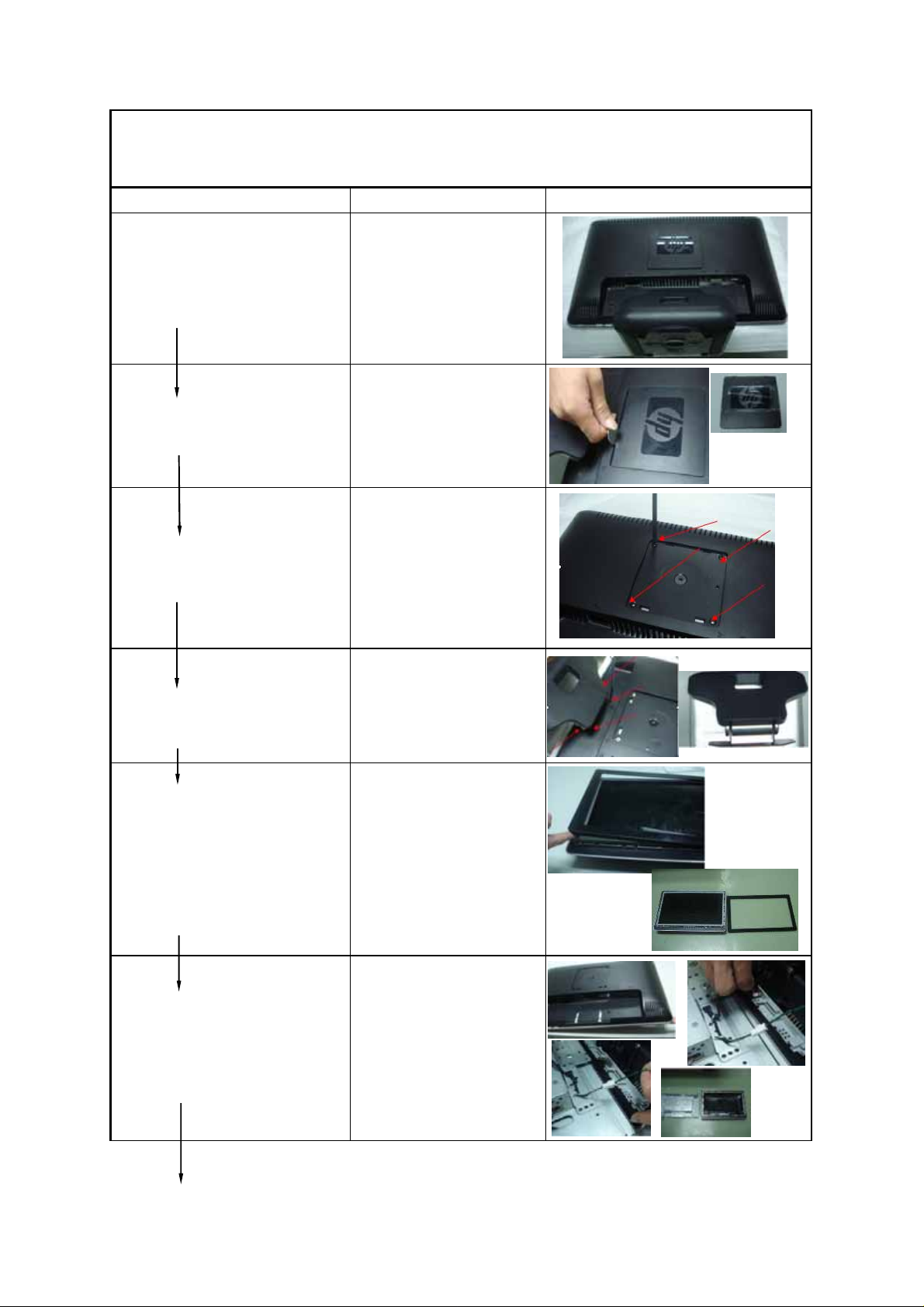
Lay the Monitor on the desk. N/A
Remove the VESA mounting cover with
hand.
Unlock the 4 screws which they fix the
VESA mounting by #2 scewdriver.
#2 Crossing Screw Driver
N/A
Photo
Unlock the 4 screws which they fix the
stand by 2# screwdriver.
Remove the front bezel out with hand. N/A
Remove the back cover out with hand. N/A
#2 Crossing Screw Driver
Page 4
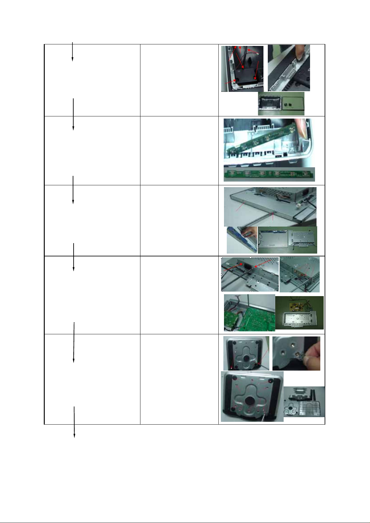
Unlock the 6 screws which fix the
speaker grill ,and take the sub-bezel out.
#2 Crossing Screw Driver
Take the keypad out. N/A
Unlock the 2 screws which fix the
chassis and panel, and then pull the
#2 Crossing Screw Driver
LVDS out .
Unlock 2 screws for DVI port, D-SUB
port, Power port, and 7 screws which
they fix between chassis PCA boards,
power board and IF board. Pull the wires
out.
Unlock the 2 screws which they fix
between the bottom-side and the base,
and then unlock the 12 screws which
they fix between the base and basecover.
#2 Crossing Screw Driver and
#1 Bushing Screw Driver
#2 Crossing Screw Driver
Page 5
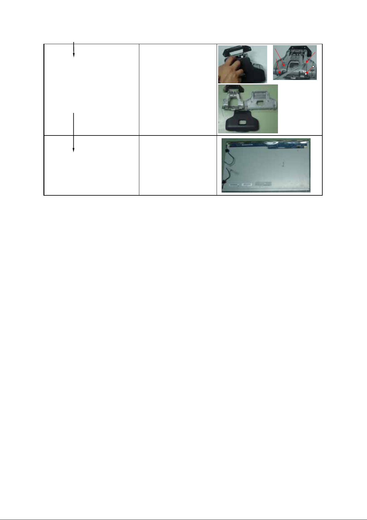
Remove the arm-rear and then unlock
the 4 screws which they fix between the
arm-front and the rion.
The panel N/A
#2 Crossing Screw Driver
Page 6

Page 7

Technical Notification
Technical Notification
Sequence of Module Disassembly for Lamp Separation ––
--Sequence of Module Disassembly for Lamp Separation
( LTM230HT01 )
( LTM230HT01 )
DATE : Oct. 08, 2008
Application Engineering 1 ,
HD development, LCD Business
Any of information, data and/or records in these documents shall be treated as “CONFIDENTIAL” and no copy thereof shall be
allowed without sender's prior written authorization. The disclosure of these documents shall be made to those who have need to
know or are intended to know.
Page 8

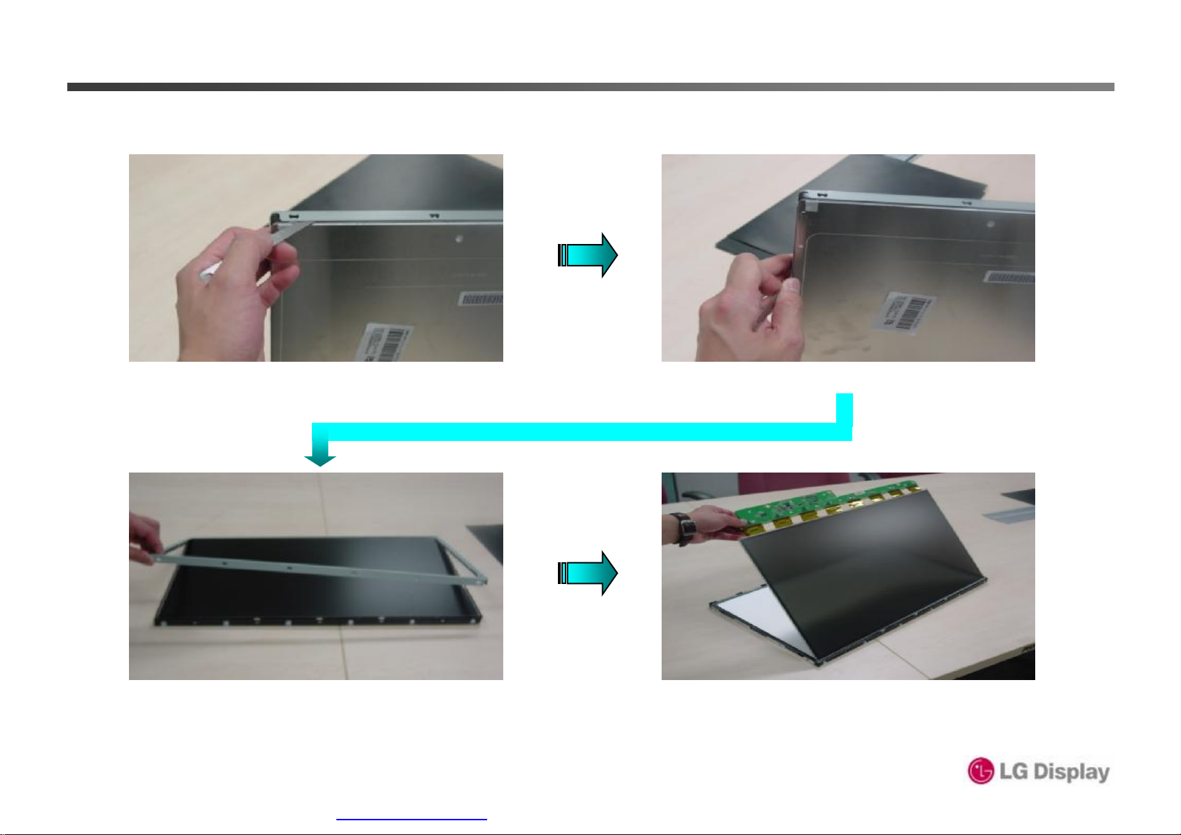
Sequence of Module Disassembly for Lamp Separation
Sequence of Module Disassembly for Lamp Separation
LTM230HT01 Module front and rare side
Disassemble top chassis and PCB cover
1 / 3
Page 9

Sequence of Module Disassembly for Lamp Separation
Sequence of Module Disassembly for Lamp Separation
Disassemble the panel from the Mold frame
Disassemble the mold frame, sheets and diffuser plate from the bottom chassis
2 / 3
Page 10

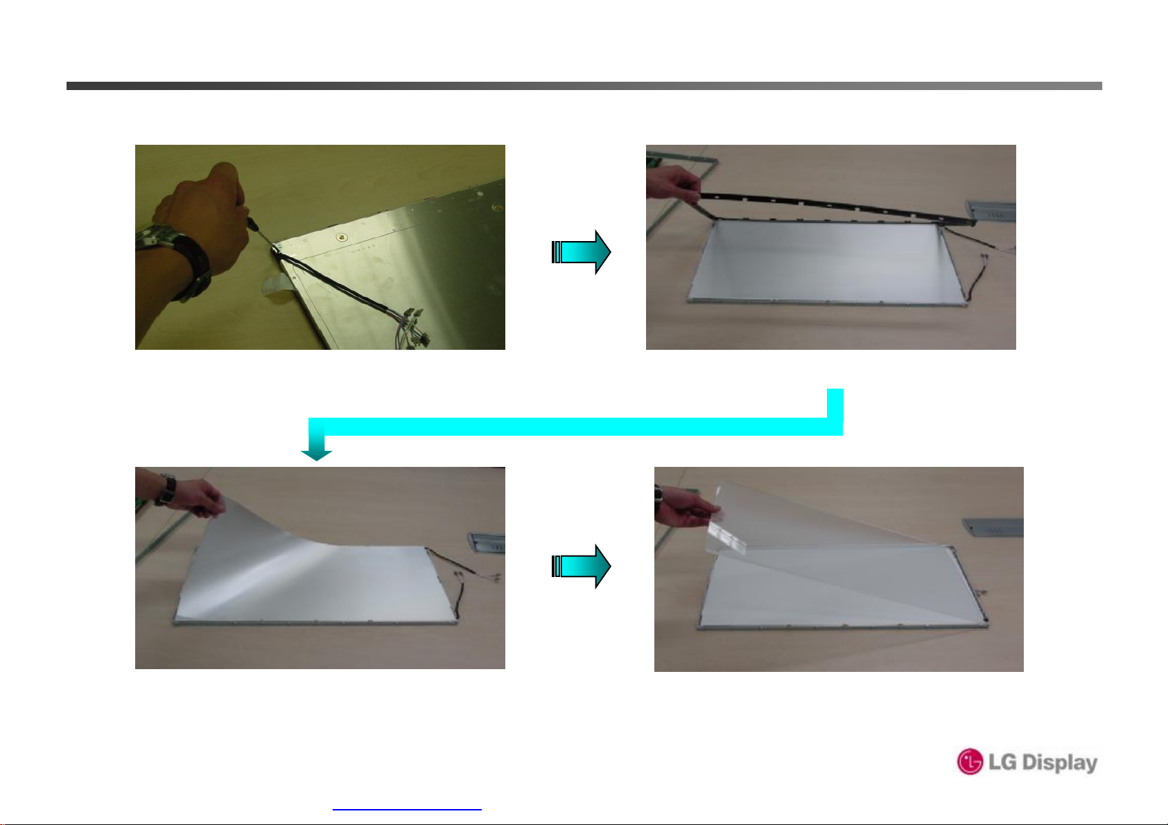
Sequence of Module Disassembly for Lamp Separation
Sequence of Module Disassembly for Lamp Separation
Separate side mold to pull out lamp
Separate lamp from backlight
3 / 3
Page 11

Method of lamp disassembly on LM230WF1-TLA3/TLB3
Step 1 : Rear side view Step 2 : Unfix the screws (3 Points)
Step 3 : Remove the Cover Shield
PDF created with pdfFactory trial version www.pdffactory.com
Step4 : Separate wires from the tape
Page 12
Method of lamp disassembly on LM230WF1-TLA3/TLB3
Step6 : Dismantle the case top(left/right)Step5 : Dismantle the case top(Down)
Step7 : Separate case top(push the case
top because of damages on COF)
PDF created with pdfFactory trial version www.pdffactory.com
Step8 : Separate Board Assy
Page 13
Method of lamp disassembly on LM230WF1-TLA3-731
Step9 : Unfix the BL Screw Step10 : remove S/Main
Step11 : remove the Optical Sheets Step12 : remove the LGP
PDF created with pdfFactory trial version www.pdffactory.com
Page 14
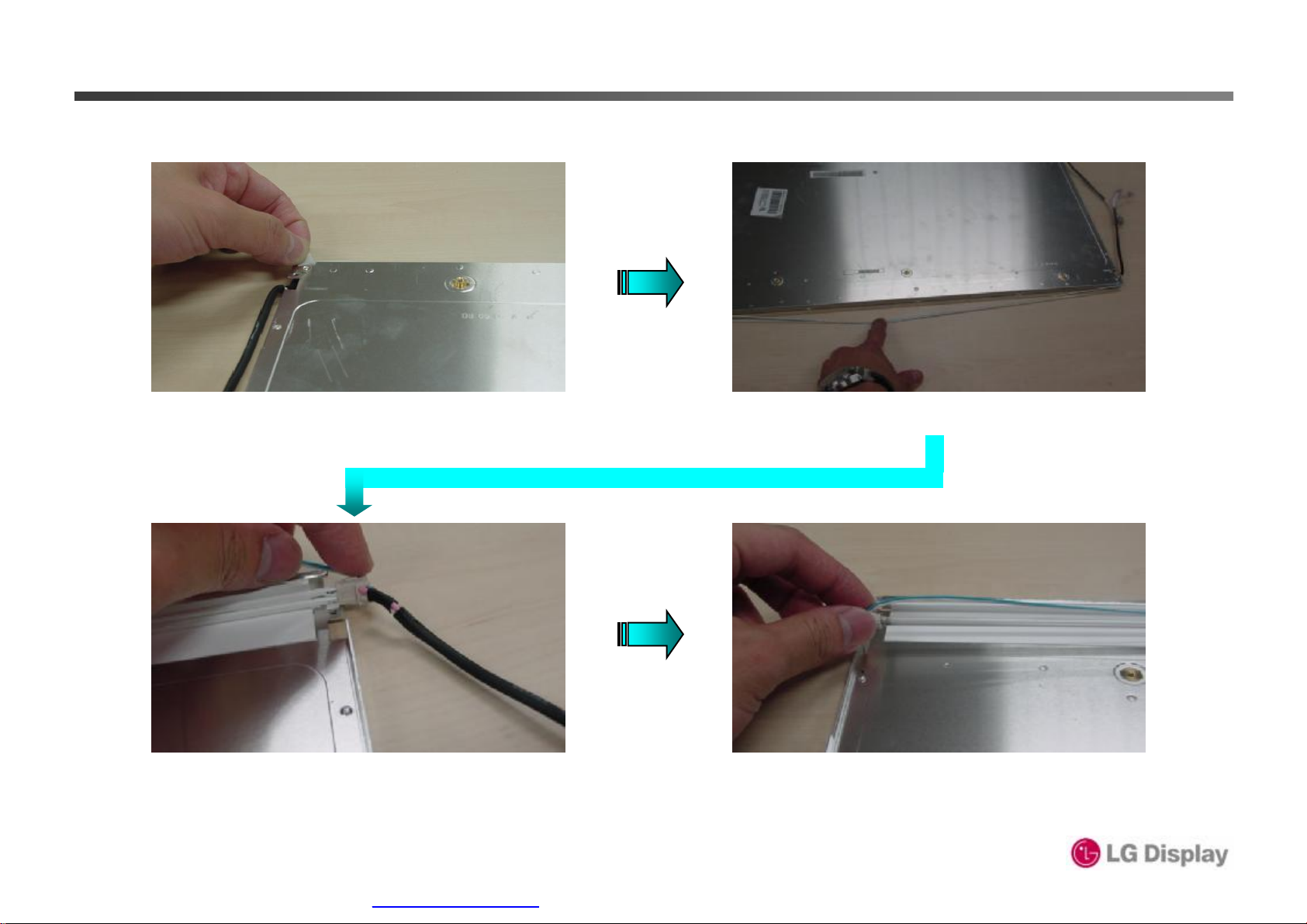
Method of lamp disassembly on LM230WF1-TLA3-731
Step13 : remove lamp wire tapes
(left/right)
Step15 : Separate Lamp holder(H) from
holder Guide of Cover bottom
Step14 : Separate wires from Cover bottom
Step16 : Separate Lamp holde(G) from
holder Guide of Cover bottom.
PDF created with pdfFactory trial version www.pdffactory.com
Page 15

Method of lamp disassembly on LM230WF1-TLA3-731
Final : Lamp Assy
PDF created with pdfFactory trial version www.pdffactory.com
 Loading...