

Page 1
HP Digital Entertainment Center
User’s Guide
Page 2

The only warranties for HP products and services are set forth in the
express warranty statements accompanying such products and services.
Nothing herein should be construed as constituting an additional
warranty. HP shall not be liable for technical or editorial errors or
omissions contained herein.
HP assumes no responsibility for the use or reliability of its software on
equipment that is not furnished by HP.
This document contains proprietary information that is protected by
copyright. No part of this document may be photocopied, reproduced,
or translated to another language without the prior written consent
of HP.
Hewlett-Packard Company
P.O. Box 4010
Cupertino, CA 95015-4010
USA
© 2004, 2005 Hewlett-Packard Development Company, L.P.
Warnings and notes
This product incorporates copyright protection technology that is
protected by method claims of certain U.S. patents and other intellectual
property rights owned by Macrovision Corporation and other rights
owners. Use of this copyright protection technology must be authorized
by Macrovision Corporation and is intended for home and other limited
viewing uses only unless otherwise authorized by Macrovision
Corporation. Reverse engineering or disassembly is prohibited.
Apparatus Claims of U.S. Patent Nos. 4,631,603, 4,577,216,
4,819,098, and 4,907,093 licensed for limited viewing uses only.
FireWire and iPod are trademarks of Apple Computer, Inc.
HP supports lawful use of technology and does not endorse or
encourage the use of its products for purposes other than those
permitted by copyright law.
Intel, Pentium, Intel Inside, and the Intel Inside logo are trademarks or
registered trademarks of Intel Corporation or its subsidiaries in the
United States and other countries/regions. Microsoft, the Microsoft
logo, Windows, and Windows XP are U.S. registered trademarks of
Microsoft Corporation.
The information in this document is subject to change
without notice.
Color-coded warnings and notes with additional text
contain important information.
w
A warning describes information you need to
avoid possible personal injury, damage to
equipment, or irrecoverable data loss.
Text set off in this manner indicates that
failure to follow directions could result in
bodily harm or loss of life.
Read and follow all warnings.
Sample warnings and notes are displayed on this page.
n
A note describes important information
you need.
Page 3

Table of Contents
Before You Begin ..................... 1
Welcome............................................................ 1
Benefits and Features............................................ 2
Functional Overview............................. 3
Front Panel..........................................................3
Memory Card Reader........................................... 5
Back Panel.......................................................... 6
Cleaning the
HP Digital Entertainment Center............................9
Shipping the
HP Digital Entertainment Center............................9
Keyboard ........................................... 10
Wireless Keyboard Operation............................. 12
Replacing the Keyboard Batteries......................... 13
Remote Control................................... 14
Remote Control Buttons....................................... 14
Remote Control Operation ..................................16
Installing the Remote Control Batteries ..................16
Safety Information................. 17
AC Power Safety Warnings ................................17
Installation Overview ............ 19
System Audio/Video Connections ....... 20
System Integration.............................................. 20
System Diagram ................................................22
Installation Guidelines ........................ 24
Placement and Ventilation Requirements ...............25
Basic Setup......................................... 27
Setting Up the
HP Digital Entertainment Center..........................27
Inventory ............................................29
Cables Included.................................................30
Connecting Audio ...................33
Audio Overview ..................................34
Audio Output Connectors....................................34
Sound Connector Jacks.......................................35
Speaker Types ...................................................35
Speaker Configurations ......................................36
Typical Audio Connection.....................38
TV Audio Connection ...........................39
Connecting TV Audio..........................................39
AV Receiver Audio Connection .............40
AV Receiver Equipment Overview ........................40
2.0 Home Stereo Installation ...............................41
2.1 Home Stereo Installation ...............................42
4.1 Home Theater Audio ....................................43
5.1 Home Theater Audio ....................................44
7.1 Home Theater Audio ....................................45
Digital Home Theater Audio ................................46
Powered Speaker Audio Connection....48
2.1 Powered Speakers .......................................49
4.1 Powered Speakers .......................................50
5.1 Powered Speakers .......................................51
7.1 Powered Speakers .......................................52
Digital Powered Speakers ...................................53
Monitor Speakers...............................................54
Audio In Connections...........................55
FM Radio Antenna...............................56
Table of Contents
Table of Contents iii
Page 4

Connecting Video Out ............ 57
Video Out Overview ...........................58
Video Out Connection Overview ......................... 58
Video Out Connectors ........................................ 59
Component Video Settings .................................. 60
TV Display Overview..........................................61
Audio and Video Switching Overview.................. 61
Using the Remote Control with Your TV................. 62
Typical Video Out Connections.............63
Video Out to TV...................................64
Video Out from AV Receiver to TV .......66
Video Out to Monitor ..........................68
Video Out to TV and Monitor...............69
Connecting TV Source In ......... 71
TV Source Overview............................72
TV Signal Source Overview................................. 72
Additional HDTV Information............................... 74
TV Source Connectors Overview.......................... 75
TV Source Connectors ........................................76
Typical TV Source Connections .............78
Antenna Connection ............................80
Antenna (NTSC) ................................................80
Antenna (ATSC)................................................. 81
Antenna (NTSC and ATSC)................................. 82
Cable Connection ................................83
Cable (NTSC) and Antenna (ATSC)...................... 83
One Cable TV Box or Digital Cable Receiver
(NTSC) and Antenna (ATSC).............................. 84
Two Cable TV Boxes, or Two Digital Cable
Receivers (NTSC) and Antenna (ATSC)................ 86
Cable Only (NTSC)............................................ 88
One Cable TV Box or
Digital Cable Receiver (NTSC) ...........................89
Two Cable TV Boxes, or
Two Digital Cable Receivers...............................91
Satellite Connection............................. 93
One Satellite Receiver (NTSC) .............................93
Two Satellite Receivers (NTSC) ............................95
Infrared Transmitter Connection .......... 97
Infrared Transmitter Overview..............................97
Infrared Transmitter Installation ............................99
Connecting Video
Equipment ............................101
Video Equipment Overview............... 102
Connectors......................................................102
Video Equipment Connection Overview ..............103
Typical Video Equipment
Connections ...................................... 104
VCR Connection................................. 105
VCR Direct In Connection..................................105
Wall to VCR to TV Using Coaxial Cable .............106
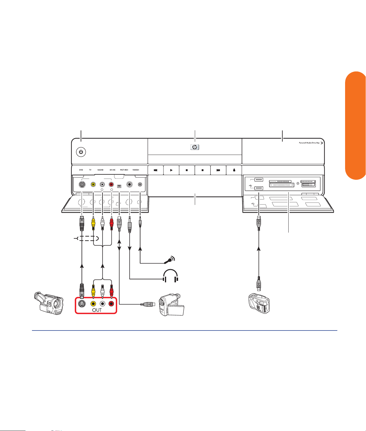
Video Camera Connection ................. 109
Connecting a Digital Video Camcorder ..............109
Connecting an Analog Camcorder.....................112
Connecting the Network .......113
Peripheral Connection Overview ....... 114
Typical Network Connections ............116
Connecting the Wireless
Network Antenna ............................. 117
Connecting a DSL/Cable Modem........ 119
iv HP Digital Entertainment Center
Page 5

Connecting Through a Router............ 120
USB Device Connection...................... 121
Digital Still Camera.......................................... 121
Other USB Devices........................................... 122
Connecting an
HP Personal Media Drive .................. 123
Installing an HP Personal Media Drive ................ 124
Disconnecting an HP Personal Media Drive......... 125
Initial Configuration ............. 127
Starting the HP Digital Entertainment
Center for the First Time.................... 128
Installing the Keyboard Batteries (Initial).............. 128
Initial Startup................................................... 129
Syncing the Keyboard ...................................... 130
Windows Welcome........................... 131
Media Center First Run...................... 132
Required Setup ................................................ 132
Optional Setup ................................................ 133
If Your Connections Don’t Work ........................ 135
Adjusting the Front Panel Display Brightness........ 135
Configuring Audio ............................ 136
Connecting Headphones ..................................136
Connecting a Microphone ................................136
Adjusting the Volume........................................ 138
Configuring Audio Output................................. 139
Configuring Video ............................ 141
Configuring Video Output................................. 141
Dual screen..................................................... 142
Adjusting the Desktop Display ...........................144
Adjusting the Display in Media Center................ 145
DVD Playback ................................................. 148
Adjusting the Display from the Desktop ...............149
HDTV Overscan Configuration...........................150
Finding ATSC HDTV and Standard
TV Channels...................................................151
Tuning the Desktop Display ...............................151
Configuring the System .....................154
Configuring the Keyboard Buttons ......................154
Registering with HP ..........................................155
Setting Up Virus Protection ................................155
Transferring Information from Your Old PC
to Your HP Digital Entertainment Center.............155
Installing Software............................................156
Utility Programs................................................156
Troubleshooting....................159
Problems and Solutions .....................160
Audio .............................................................160
Video .............................................................162
System............................................................164
Getting Help......................................170
Help and Support Center ..................................170
HP Support...................................................... 170
Warranty and Support Guide............................171
Updates from HP..............................................173
Microsoft Web Site ..........................................173
Appendix A: Replacing the
Hard Disk Drive....................175
Important Information About
Recorded TV Programs ....................................175
Procedure .......................................................175
Index ...................................179
Table of Contents
Table of Contents v
Page 6

vi HP Digital Entertainment Center
Page 7
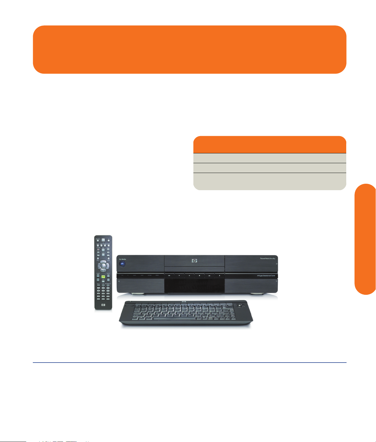
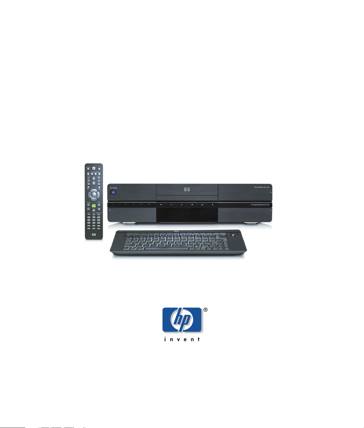
Before You Begin
Welcome
Thank you for purchasing the HP Digital Entertainment
Center. Your HP Digital Entertainment Center puts you in
control of your complete home entertainment experience.
Enjoy your TV, movies, music, photos, and home videos
with one simple interface. Pause and replay live TV, and
record your favorite TV shows. Use a television program
guide without a monthly fee. Capture, personalize, and
create DVDs of your home movies, and back up your
photos, music, or favorite TV programs onto DVD.
Use other entertainment equipment — like a TV, AV
receiver, satellite receiver, and digital camera — with the
HP Digital Entertainment Center to create an integrated
system. Access all of your TV programs, videos, pictures,
music CDs, and DVDs using Microsoft
software and the remote control.
®
Media Center
This User’s Guide helps you to set up the HP Digital
Entertainment Center to use with your audio/video
system.
Chapter Contents:
“Functional Overview” on page 3
“Keyboard” on page 10
“Remote Control” on page 14
Before You Begin
The HP Digital Entertainment Center
Before You Begin 1
Page 8

Benefits and Features
Benefits
■ Complete home digital entertainment solution for
your living room.
■ Watch, pause, and replay live TV on one channel
while recording another (select models only).
■ Schedule future recordings with the complimentary
TV programming guide (no charge — separately
purchased broadband Internet service required).
■ Burn a DVD of your favorite TV shows or home
videos.
■ Play DVDs in 7.1 surround sound (surround sound
system is required and sold separately).
■ Burn music audio CDs (for lawful use only).
Product features
■ Sophisticated, sleek, stackable case fits into your
AV cabinet
■ Built-in standard-definition TV tuner, NTSC
(Dual tuners for select models only)
■ Built-in high-definition ATSC HDTV tuner
(select models only)
■ Personal video recorder (PVR) with a complimentary
TV programming guide (no charge)
■ Built-in FM radio tuner
■ HP Personal Media Drive
■ Front panel media info display
■ CD/DVD double-layer, multiformat player/recorder
■ 9-in-1 media card reader
■ Store audio CDs in an easy-to-use music jukebox.
■ Listen to your collection of MP3 and AAC music.
■ Burn picture slide shows to CD or DVD.
■ View and edit your favorite digital photos.
■ Store your digital content on the HP Personal Media
Drive.
■ Download movies on demand (fees may apply —
separately purchased broadband Internet service
required).
■ Instant-message friends (separately purchased
broadband Internet service required).
■ Rear and front AV connectors:
■ Digital Audio Out: Optical and coaxial S/PDIF
5.1 surround
■ Analog Audio Out: Up to 7.1 channels
■ Video Out: DVI, VGA, S-video, component,
composite video
■ LAN Ethernet 10/100/1000
■ Integrated 802.11 b/g wireless
■ Front AV, USB, and FireWire
®
(IEEE 1394)
connectors for video capture
■ Full function remote control
■ Lap-sized, compact wireless keyboard with
integrated trackball mouse
2 HP Digital Entertainment Center
Page 9
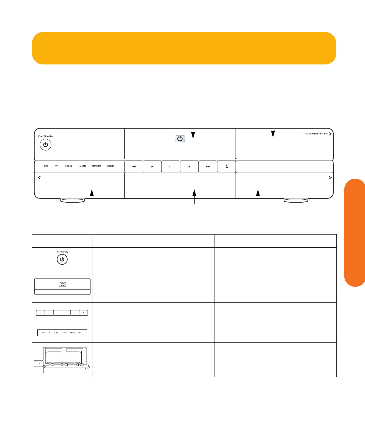
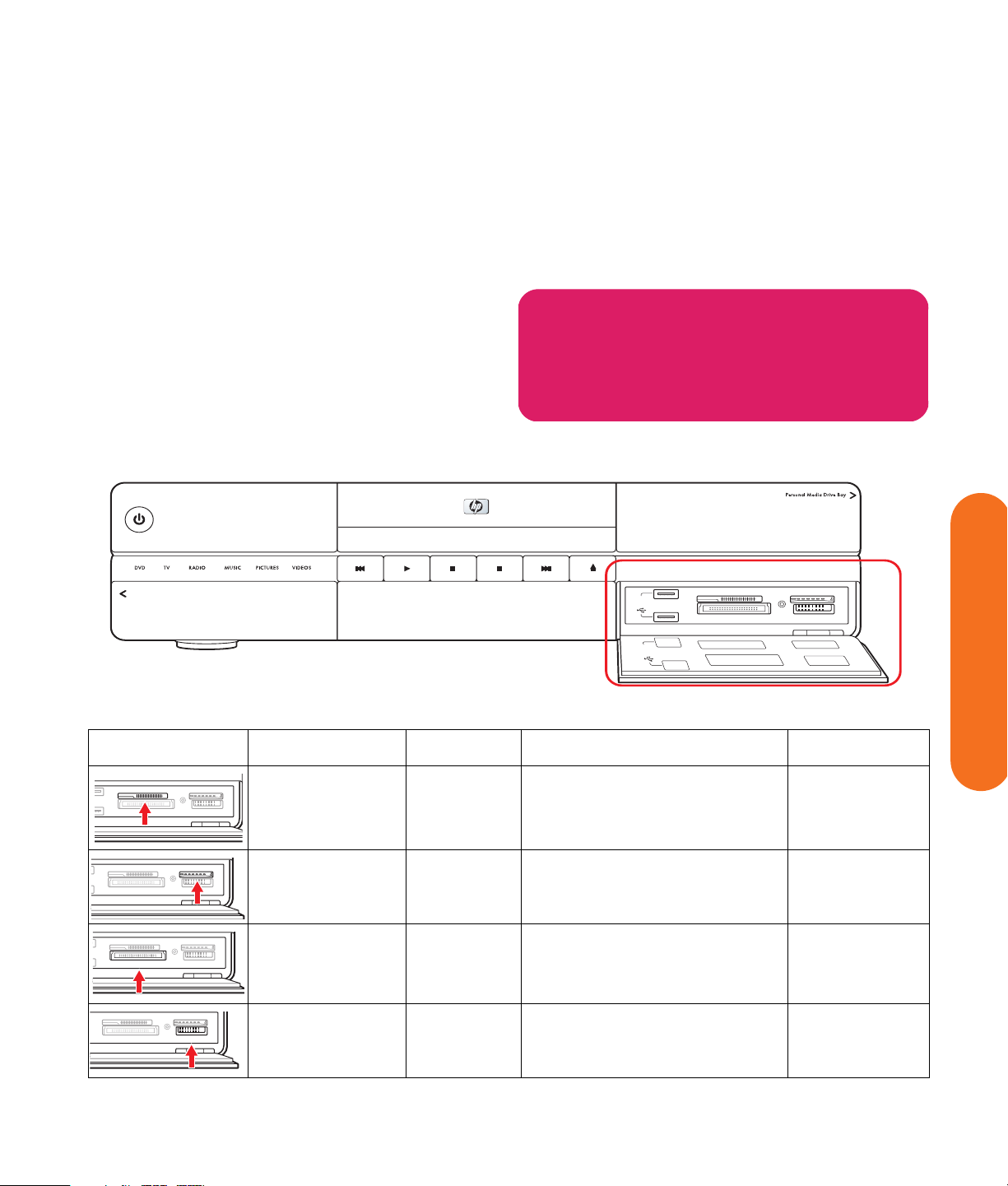
Functional Overview
l
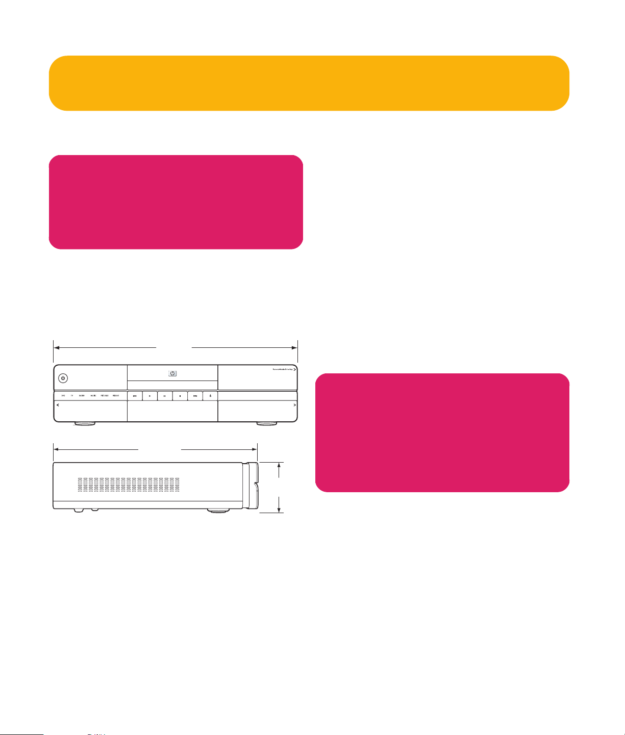
Front Panel
The following illustration shows a typical HP Digital
Entertainment Center front panel.
Your model might not have all features.
CD/DVD
HP Persona
Media Drive Bay
HP Digital Entertainment Center
Front panel
Item Function Comments
AV inputs USB and card readers
On/Standby (power) button and LED
Push to turn on. Push for standby.
Press and hold button 4 seconds to turn off.
CD/DVD player/recorder
Progressive scan DVD player plus
double-layer DVD+RW/DVD-R recorder
Transport control buttons Replay, Play, Pause, Stop, Skip, Eject
Experience mode status indicators White indicates DVD, TV, radio, music,
Personal Media Drive Bay Removable HP Personal Media Drive
Media info display
Solid blue: On
Solid amber: Standby
CD/DVD, multiformat
Push the Eject button to open.
Push the tray or Eject button to close.
pictures, videos, activities in Media Center
behind top right door, for additional
storage for recorded TV shows and digital
content
Before You Begin
Before You Begin 3
Page 10
Item Function Comments
E
2
N
CON
1
C
CONNECT
ED
.0
EED
2.0
FRONT INPUT
S-VIDEO VIDEO AUDIO DV INL
S-VIDEO VIDEO AUDIOL
HP Digital Entertainment Center
SmartMedia / xD
CompactFlash I/II
SmartMedia / xD
CompactFlash I/II
KEYBOARD
CONNECT
S-VIDEO
FRONT INPUT
FRONT INPUT
MMC / SD
MS / MS PRO
MMC / SD
MS / MS PRO
9-in-1 memory card readers
SmartMedia/xD, MMC/SD,
CompactFlash I/II, Microdrive, MS/MS-Pro
USB 2.0 (2)
Card readers behind lower right door
LED: Green (with media inserted)
Off (no media inserted)
See “Memory Card Reader” on page 5.
Media info display Front status panel for all media
information. Front-panel text content
displayed from Media Center
KEYBOARD
CONNECT
1394
R
HEADPHONES
Behind left door
MIC I
AV connectivity for capturing analog and
Front AV inputs — see below
digital video from camcorders
Keyboard connect switch for wireless
keyboard synchronization
Blinking green LED indicates keyboard
activity. Special blink status indicates sync
with keyboard.
S-video In Y/C video, analog 4-pin
Video In Composite video RCA jack
R
Audio In White: Left
HEADPHONES
MIC INHEADPHONES
MIC INHEADPHONES
R
Red: Right, RCA jacks
1394 DV In FireWire (IEEE 1394), 4-pin input-output
MI
for digital video
Headphone Out 1/4 inch jack
Microphone In 1/8 inch mini-jack
S-VIDEO VIDEO AUDIODL
1394
R
AUDIO DV INL
1394
R
O DV IN
1394
R
DV IN
4 HP Digital Entertainment Center
Page 11
Memory Card Reader
The HP Digital Entertainment Center 9-in-1 card readers
Two USB 2.0 connectors are also included.
are on the front panel, located behind a door for quick
transfer of digital photos and other digital content. Four
horizontal card slots accept memory cards.
An in-use light-emitting diode (LED) indicates card reader
activity when the HP Digital Entertainment Center is
reading or writing data. Wait until the LED stops blinking
before removing media.
Removing media when the in-use light is
blinking may cause damage.
w
Digital cameras and other digital devices use memory
cards, or media, to store digital picture files.
On/Standby
Your model might not have all features.
HP Digital Entertainment Center
HI SPEED
USB 2.0
HI SPEED
USB 2.0
SmartMedia / xD
CompactFlash I/II
SmartMedia / xD
CompactFlash I/II
MMC / SD
MS / MS PRO
MMC / SD
MS / MS PRO
Memory card readers
Item Name Slot Supports Insert media
Before You Begin
SmartMedia / xD
CompactFlash I/II
SmartMedia / xD
CompactFlash I/II
SmartMedia / xD
CompactFlash I/II
SmartMedia / xD
CompactFlash I/II
MMC / SD
MS / MS PRO
MMC / SD
MS / MS PRO
MMC / SD
MS / MS PRO
MMC / SD
MS / MS PRO
SmartMedia/xD Upper-left SmartMedia (SM) memory card/
xD media
MMC/SD Upper-right MultiMediaCard (MMC)
Secure Digital (SD) memory card
CompactFlash I/II
Microdrive
Lower-left CompactFlash Type I, II media
Microdrive disk drive
MS/MS-Pro Lower-right Memory Stick (MS)
Memory Stick (MS-Pro)
Facing up
Facing up
Receptacle
edge (holes)
Facing up
Before You Begin 5
Page 12
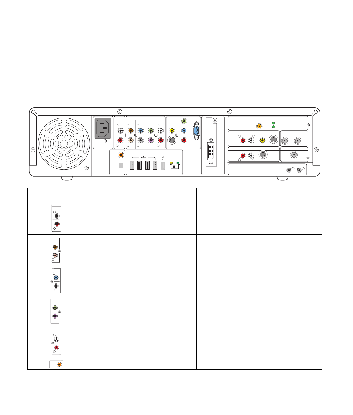
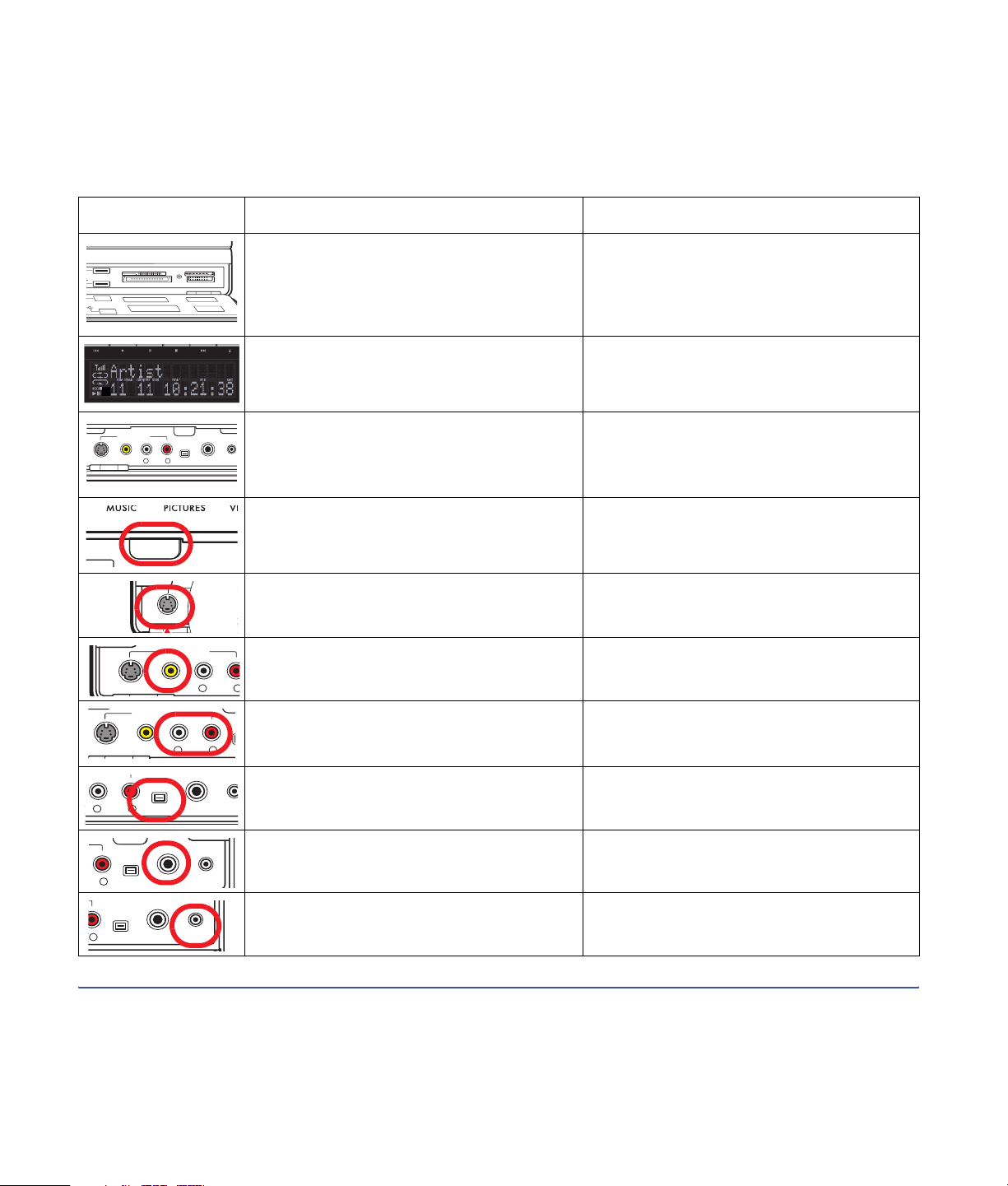
Back Panel
The following illustration shows the HP Digital Entertainment Center back panel.
(Location, availability, and number of connectors may vary.)
WIRELESS LAN 802.11 b/g
REMOVABLE ANTENNA
TV SOURCE 1 IN
R
L
AUDIO
TV SOURCE 2 IN
RL
VIDEO
INFRARED TRANSMITTER OUT
S-VIDEO
S-VIDEOAUDIO
ACTIVITY
LINK
CABLE/ANT. IN FM ANTENNA IN
DUAL
TUNER
HDTV / SDTV ANT. IN
ATSC TUNER
100-240V- 4/A 50/60Hz
AC IN
AUDIO IN
COAXIAL
OPTICAL
DIGITAL
SURROUND
BACK
L
L L L
R
R R
AUDIO
OUT
AUDIO 7.1 PRE-OUT
SURROUND CENTER
HI SPEED USB 2.0 ETHERNET1394
SUB
WOOFER
FRONT
R
VIDEO OUT
VIDEO
S-VIDEO COMPONENT
10/ 100/ 1000
Y
Pb
Pr
DVI
VGA
DIGITAL VIDEO OUT
Item Connector Type Color Supported format
AUDIO IN
L
R
SURROUND
BACK
L
R
SURROUND
L
Audio In RCA jacks White: Left
Red: Right
Audio 7.1 Pre-Out
Surround Back
Audio 7.1 Pre-Out
Surround
RCA jacks Brown: Left
Beige: Right
RCA jacks Blue: Left
Grey: Right
Analog stereo
Analog:
7.1
Analog:
7.1, 6.1, 5.1, 4.1
75
COAXIAL
12
Ω
R
CENTER
Audio 7.1 Pre-Out
Center/Subwoofer
SUB
WOOFER
FRONT
L
Audio 7.1 Pre-Out
Front
R
COAXIAL
Digital Audio Out Coaxial Orange S/PDIF 5.1 only
6 HP Digital Entertainment Center
RCA jacks Green: center
Purple:
subwoofer
RCA jacks White: Left
Red: Right
Analog:
7.1, 6.1, 5.1
Analog stereo:
7.1, 6.1, 5.1, 4.1, 2.1, 2.0
Page 13
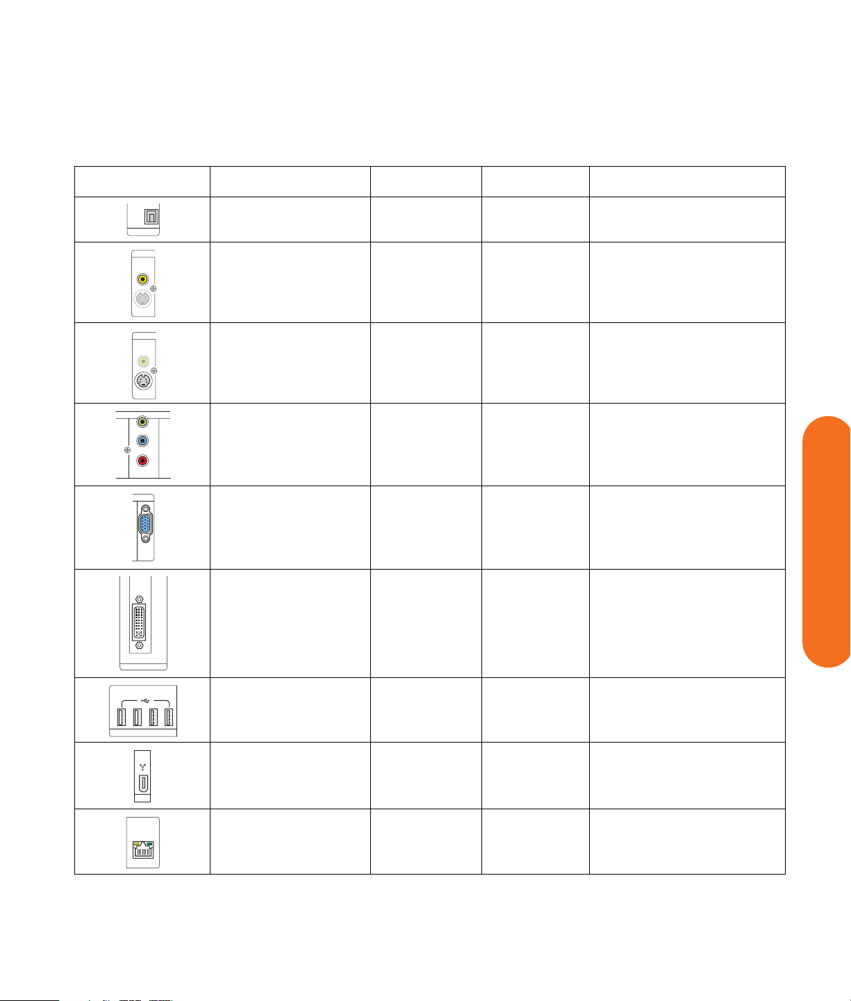
Item Connector Type Color Supported format
OPTICAL
AUDIO
DIGITAL
OUT
VIDEO
VIDEO
S-VIDEO
VIDEO
VIDEO
S-VIDEO
VIDEO OUT
Y
Pb
Pr
COMPONENT
OUT
VGA
DVI
DIGITAL VIDEO OUT
Digital Audio Out Optical Gray S/PDIF 5.1 only
Video Out
RCA jack Yellow Analog: Interlaced scan
(Composite)
S-video Out Y/C video
4-pin
Component Video Out
3 RCA jacks Green: Y
(Not all modes support
DVD playback due to
content protection.)
Black Analog: Interlaced scan
Up to 1024 x 768 @ 60 Hz
Analog: Interlaced or
Blue: Pb
Red: Pr
progressive scan
interlaced displays up to
1080i, Plus 480p, 720p
VGA Out 15-pin D-sub Blue Analog:
Up to 2048 x 1536 with
panning depending on
display size
Digital Video
Out (DVI)
DVI-I 29-pin
D-sub digital/
analog
White Digital:
Up to 1600 x 1200
Up to 2048 x 1536 with
panning depending on
display size
Before You Begin
HI SPEED USB 2.0
1394
10/100/1000
ETHERNET
USB 2.0
(high speed)
1394
(for digital video or
other device)
Ethernet
10/100/1000
4 ports Silver USB 2.0
6-pin DV input/
Silver FireWire (IEEE 1394)
output
RJ-45 N/A 10/100/1000
Before You Begin 7
Page 14
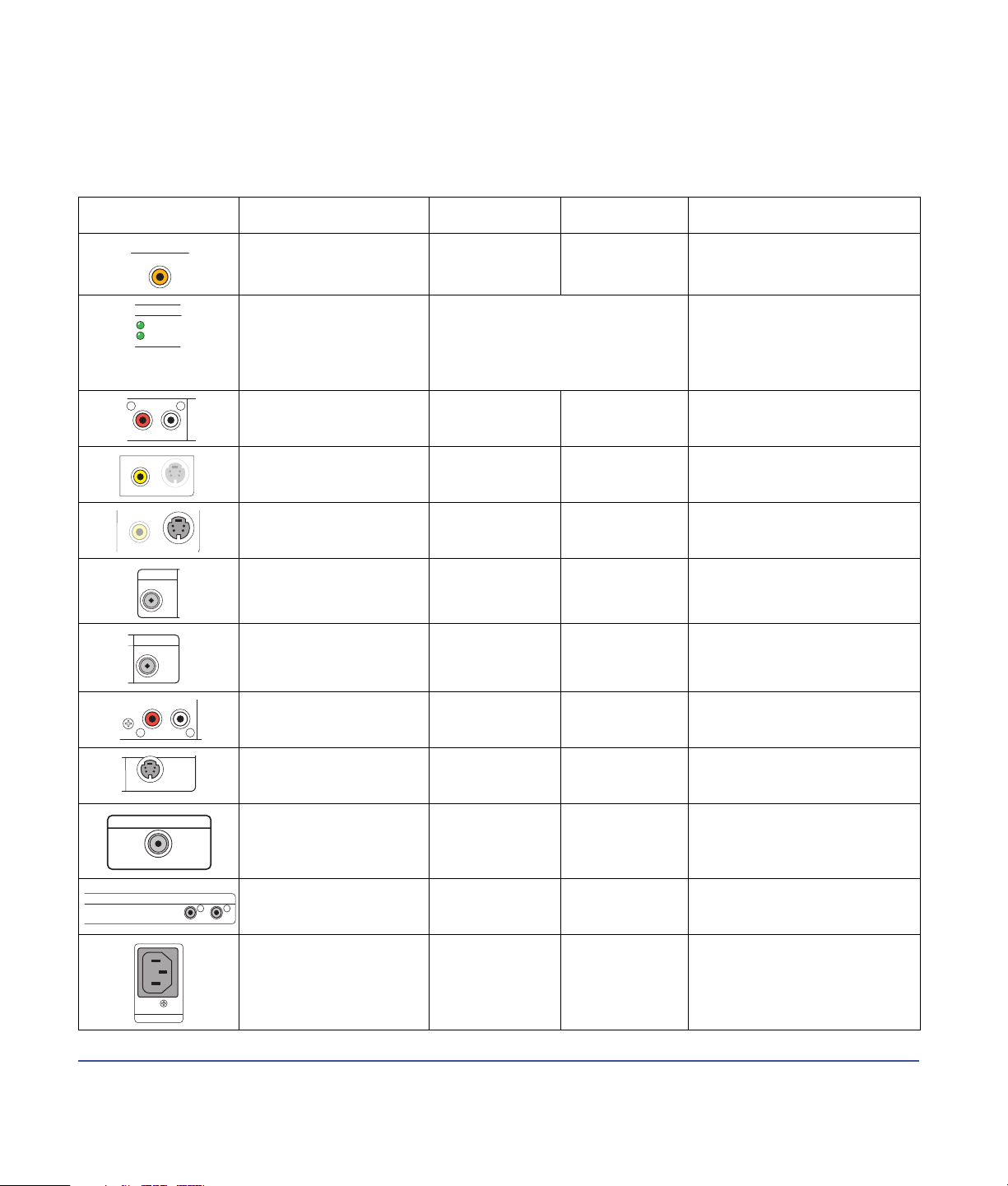
Item Connector Type Color Supported format
WIRELESS LAN
REMOVABLE ANTENNA
802.11 b/g
ACTIVITY
LINK
R
AUDIO
S-VIDEOVIDEO
S-VIDEOVIDEO
CABLE/ANT. IN
DUAL
TUNER
FM ANTENNA IN
75Ω
L
COAXIAL
R
R
AUDIO
Wireless LAN Removable
Gold 802.11 b/g
antenna
LEDs (2)
Activity: Blinks
when transmits/
receives data
L
Audio
TV Source 1 In
Video (Composite)
Link: Solid green when wireless
LAN is enabled and connected.
Blinks when wireless LAN is
scanning.
RCA jacks White: Left
Red: Right
RCA jack Yellow Analog:
TV Source 1 In
S-video
TV Source 1 In
Y/C video
Analog 4-pin
Black Analog:
Wireless LAN 802.11b/g
Analog
Up to 640 x 480 @ 60 Hz
Up to 640 x 480 @ 60 Hz
Cable/Antenna In Coaxial Silver RF NTSC with internal splitter
to dual-tuners
FM Antenna In 75 Ohm
Silver FM radio, RF
Coaxial
Audio TV Source 2 In
L
(Select models only)
RCA jacks White: Left
Red: Right
Analog
S-video TV Source 2 In
S-VIDEO
HDTV / SDTV ANT. IN
(Select models only)
HDTV/SDTV Ant. In
(Select models only)
ATSC TUNER
INFRARED TRANSMITTER OUT
Infrared Transmitter Out
12
(2 outputs)
AC In AC 110–240V
110-240V 50-60Hz
AC IN
8 HP Digital Entertainment Center
Y/C video
Analog 4-pin
Black Analog:
Up to 640 x 480 @ 60 Hz
Coaxial Silver RF ATSC
(from UHF and VHF antenna)
1/8 inch
Silver Remote infrared (IR Blaster)
mini-jack
Black Power
50–60 Hz
Page 15

Cleaning the HP Digital Entertainment Center
The HP Digital Entertainment Center is a high-quality
device that requires special care when cleaning. To clean
the HP Digital Entertainment Center, follow these steps:
1 Turn off the HP Digital Entertainment Center and
connected equipment.
2 Unplug the HP Digital Entertainment Center from the
wall outlet before cleaning.
w
3 Use a soft dry cloth for cleaning.
4 Plug in the HP Digital Entertainment Center.
5 Turn on connected equipment and the HP Digital
Entertainment Center.
Do not use liquid cleaners or aerosol cleaners
to clean your HP Digital Entertainment Center.
Do not use benzene, thinner, ammonia, or
any other volatile substances. These
chemicals may damage your unit.
Shipping the HP Digital Entertainment Center
Keep the original packing box in a storage area. You
may need it later if you move or ship your HP Digital
Entertainment Center.
Before You Begin
Before You Begin 9
Page 16
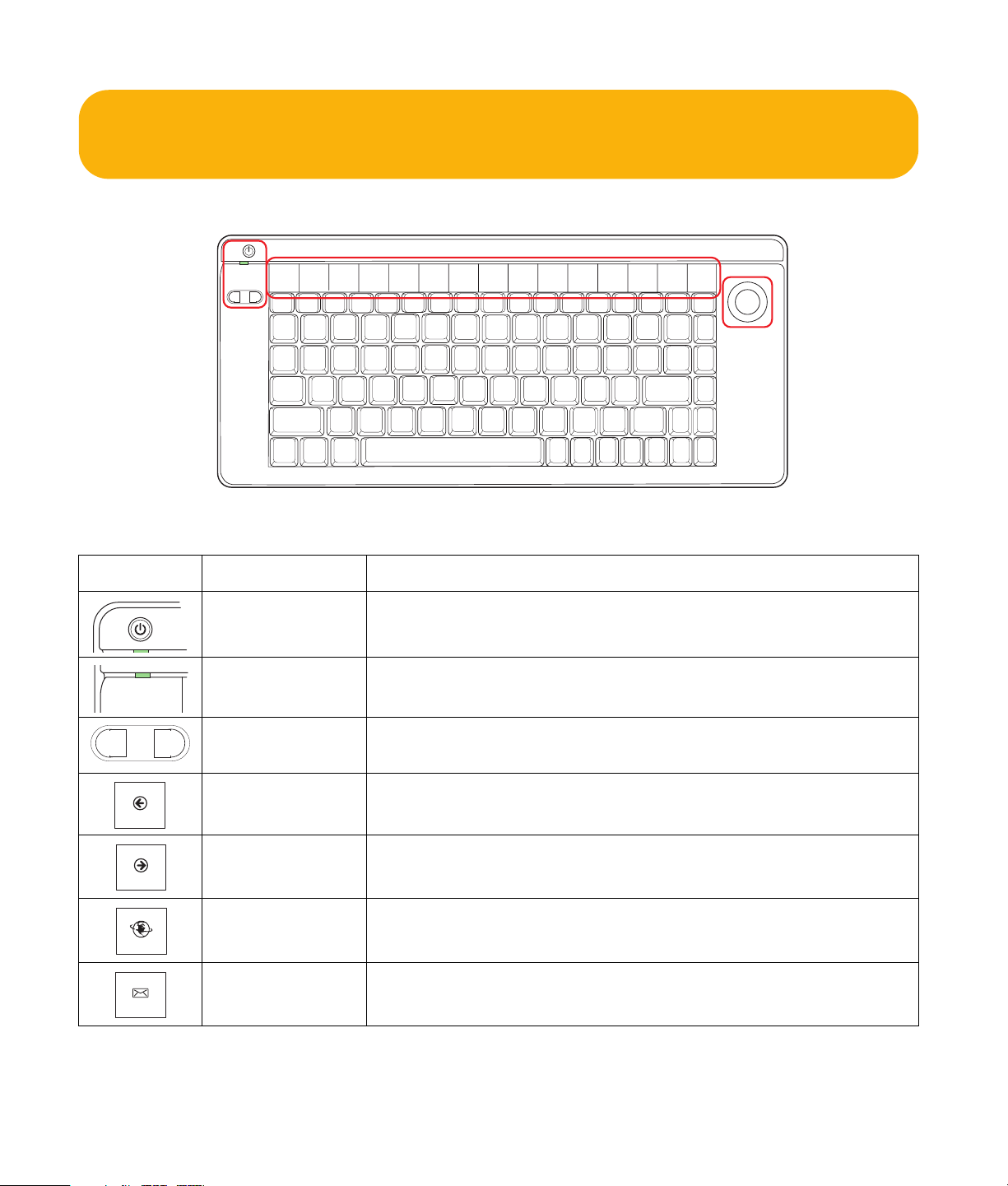
Keyboard
The following illustration shows the HP Digital Entertainment Center wireless keyboard.
Left, right
mouse button
The following table shows the wireless keyboard features and function keys from left to right.
Icon Item Description
On/Standby Turns HP Digital Entertainment Center on, when in standby.
Places HP Digital Entertainment Center in standby.
Indicator light Amber: Caps Lock on.
Green: Key or mouse button activity.
Mouse button
Left-click, right-click.
left, right
TrackBall
Back Displays previously viewed Media Center or browser page.
Back
Forward Displays next viewed Media Center or browser page.
Forward
Internet Opens your Internet browser.
Internet
E-mail Opens an Internet e-mail page or your e-mail software.
E-mail
10 HP Digital Entertainment Center
Page 17

Icon Item Description
Messenger Opens your instant messaging program.
Messenger
Minimize Minimizes the Media Center application.
Minimize
Maximize Maximizes the Media Center application.
Maximize
Media
Center
Previous
Play
Pause
Next
Vol
Vol
Mute
Media Center Starts Media Center.
Previous Selects previous media track.
Play Plays media.
Pause Pauses media.
Next Selects next media track.
Before You Begin
Vol – Decreases speaker volume.
Vol + Increases speaker volume.
Mute Turns speaker sound on and off.
Trackball Moves cursor on screen.
Before You Begin 11
Page 18
n
The Internet, E-mail, and Messenger buttons
can be reconfigured to open a Web site or
software program. See “Configuring the
Keyboard Buttons” on page 154. Refer to the
Media Center Edition 2005 Software Guide.
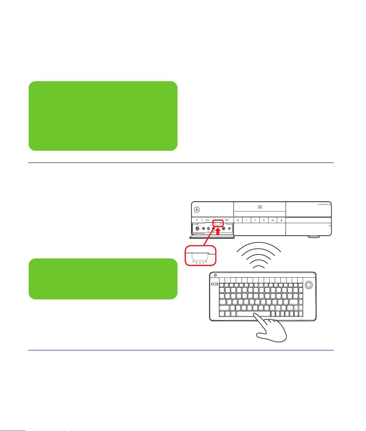
Wireless Keyboard Operation
Your HP Digital Entertainment Center includes a wireless
keyboard that uses a built-in receiver/transmitter instead
of a connector cable to communicate. The Keyboard
Connect button, behind the lower-left door of the
HP Digital Entertainment Center front panel, has an
LED that indicates receiver activity. Approximate range
is 12 feet (3.66 meters).
n
Use only alkaline batteries in the keyboard.
On/Standby
FRONT INPUT
S-VIDEO VIDEO AUDIO DV INL
KEYBOARD
CONNECT
KEYBOARD
CONNECT
1394
R
MIC INHEADPHONES
HP Digital Entertainment Center
12 HP Digital Entertainment Center
Page 19
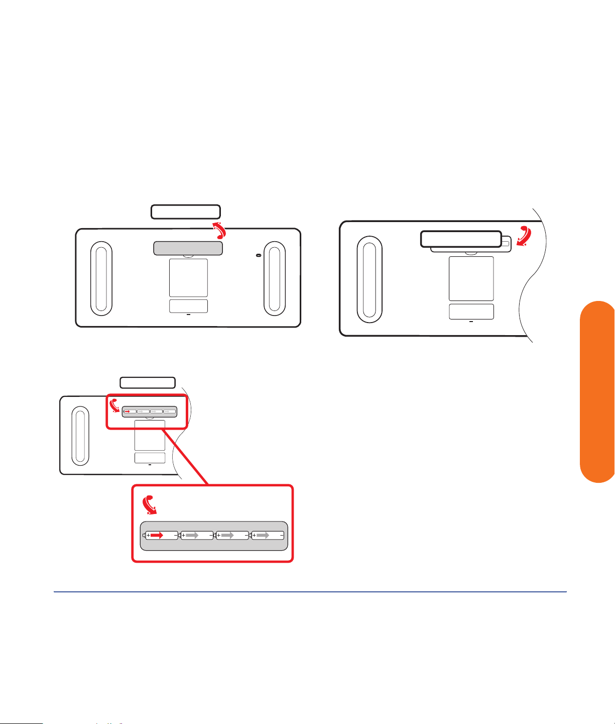
Replacing the Keyboard Batteries
Keep spare batteries on hand. Battery life will vary with
the use of the system.
1 Slide the battery cover off the back of the keyboard.
2 Insert four AA batteries (alkaline). Make sure the
battery positive and negative ends are inserted
correctly!
3 Replace the battery cover.
4 Make sure the HP Digital Entertainment Center is
powered on.
5 Test the keyboard.
■ The keyboard is set to connect to the HP Digital
Entertainment Center automatically.
6 If the keyboard does not operate:
a Check the battery orientation.
Before You Begin
b Sync the keyboard. See “Syncing the Keyboard”
on page 130.
If you have no batteries and must use a keyboard, attach
a USB keyboard to the back or front panel. You can also
use the remote control for many functions as a temporary
substitute.
Before You Begin 13
Page 20
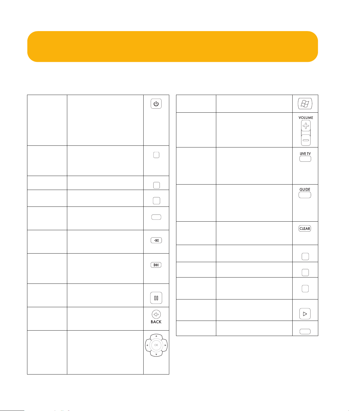
Remote Control
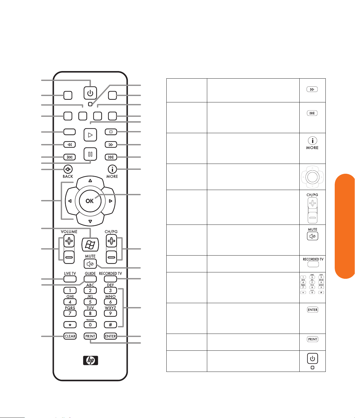
Remote Control Buttons
(Features and location may vary. Refer to the specific documentation for other remote controls.)
AStandby Puts the HP Digital
Entertainment Center into
and out of a powerreduced standby state.
It does not turn the
HP Digital Entertainment
Center off.
BDVD
Menu
Opens Play DVD window
in Media Center or opens
the main menu of a DVD
movie, if available.
CMusic Starts My Music.
DRadio Starts FM Radio.
ERecord Records selected television
program and stores it on
the hard disk drive.
FRew (Rewind) Moves the media
backward (press button for
three speeds).
GReplay Rewinds live or recorded
TV back 8 seconds, or to
beginning of music track
or DVD chapter.
HPause Pauses audio and video
tracks and live or recorded
TV programs.
JBack Returns to the previous
window within Media
Center.
KArrows Buttons move the cursor to
navigate within all Media
Center windows. They
also move forward and
backward through slideshow images.
DVD MENU
MUSIC
RADIO
RECORD
REW
REPLAY
PAUSE
LMedia
Center
Opens Media Center to
the main menu.
MVolume Increases (+) and
decreases (–) sound.
NLive TV Is a shortcut to view live
TV. It also moves to the
current point in a live TV
program after pausing
live TV.
OGuide Opens the Television
Program Guide to display
available TV channels and
programs to watch and
record.
PClear Deletes the selection and
works as the Backspace
key does on a keyboard.
QTV Starts My TV.
RPictures Starts My Pictures.
SVideos Starts My Videos.
TPlay Plays the selected media.
UStop Stops the selected media.
TV
PICTURES
VIDEOS
PLAY
STOP
14 HP Digital Entertainment Center
Page 21
A
B
C
D
G
H
DVD MENU
TV
AF
Q
MUSIC PICTURESVIDEOSRADIO
R
S
RECORD
PLAY
STOP
E
REW
F
REPLAY
PAUSE
FWD
SKIP
T
U
V
W
J
X
VFwd (Fast-forward) Moves media
forward (press button for three
speeds).
WSkip Moves media forward — for
example, 30 seconds in videos
and live TV, one music track, or
one DVD chapter.
XMore (i) Displays available information
about a selected media file
and displays more information
and options.
YOK Selects the desired action or
window option. It acts as the
FWD
SKIP
OK
Enter key.
K
L
M
N
O
P
Y
Z
AA
AB
AC
AD
AE
ZCH/PG Up (+) and down (–) change the
TV channel or move pages up
and down, depending on
available options.
AA Mute Turns sound off. The word Mute
is displayed on the Media
Center screen when Mute is
turned on.
AB Recorded
TV
AC 0 to 9,
#, *
Opens the Recorded TV
window.
Numeric keypad buttons to
change channels or enter text
into the Media Center search or
text box.
AD Enter Selects the desired action or
window option. In full-screen
mode, press Enter to return to the
last channel you were watching.
AE Print Prints selected content on the
screen.
AF LED Activity indicator lights on
pressing a button.
Before You Begin
Before You Begin 15
Page 22
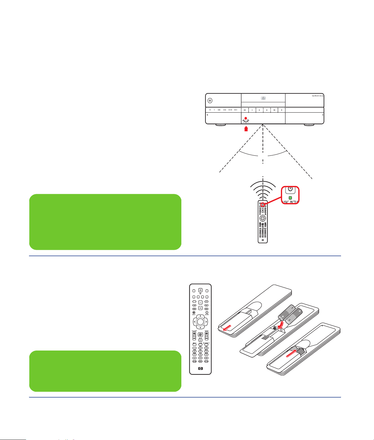
Remote Control Operation
Use the remote control to open the Media Center
program; view TV, record TV programs, play previously
recorded TV programs, and play music, movies, or video.
See “Using the Remote Control” in the Media Center
Edition 2005 Software Guide for detailed instructions on
using the features of the remote control.
To use the remote control, just point it at the HP Digital
Entertainment Center and press a button. Use the remote
control at a maximum distance of 26 feet (8 meters) from
the remote sensor and at a maximum of 45 degrees
(90 degrees total) from the center of the remote sensor.
The remote control will not operate until the HP Digital
Entertainment Center is powered on and fully booted up.
n
Media Center must be in full-screen mode (or
have focus) for consistent remote control
operation. Performance may vary.
On/Standby
HP Digital Entertainment Center z545
LED
90˚
~26
feet
Indicator
Light
Remote operation
Installing the Remote Control Batteries
1 Slide the battery cover off the back of the remote
control.
2 Insert the two AA alkaline batteries (provided). Make
sure the battery positive and negative ends are
inserted correctly!
3 Replace the battery cover.
4 Test the remote control by pressing any key.
The indicator light should blink.
DVD MENU
RECORD
REPLAY
TV
MUSICPICTURES VIDEOSRADIO
PLAY
STOP
REW
FWD
PAUSE
SKIP
OK
n
Use only alkaline batteries in the remote.
16 HP Digital Entertainment Center
Page 23

Safety Information
Read Instructions before installing or operating your
HP Digital Entertainment Center.
Follow the instructions provided.
Heed all safety warnings and notes.
Refer to the Warranty and Support Guide for additional
safety information.
“AC Power Safety Warnings” on page 17
w
Please read this important safety
information.
AC Power Safety Warnings
Use the right AC source. The power supply is preset
for the country/region in which you purchased the
HP Digital Entertainment Center. If you move to another
country/region, please make sure you check its voltage
requirements before plugging your HP Digital
Entertainment Center into an AC power outlet.
A power cord is included with your HP Digital
Entertainment Center. If another cord is used, use only
a power source and connection appropriate for this
HP Digital Entertainment Center.
Install the system near an AC outlet. The AC power cord
is your HP Digital Entertainment Center’s main AC
disconnecting device and must be easily accessible at all
times. For your safety, the power cord provided with your
system has a grounded plug. Always use the power cord
with a properly grounded wall outlet to avoid the risk of
electric shock.
■ Do not open top cover.
■ Risk of electric shock.
■ No user-serviceable parts inside top cover.
To reduce the possibility of an electric shock from the
telephone network, plug your system into the AC outlet
before connecting it to the DSL/telephone line. Also,
disconnect the DSL/telephone line before unplugging
your system from the AC power outlet.
This product has not been evaluated for connection to an
“IT” power system (an AC distribution system with no
direct connection to earth, according to IEC 60950).
Ground your system. To reduce the risk of electric
shock or damage to your equipment, do not disable the
power cord grounding feature. The grounding plug is an
important safety feature. Connect the equipment to a
grounded (earthed) power outlet.
For your safety, be sure that the grounded power outlet
into which you plug the power cord is easily accessible to
the operator and is located as close to the equipment as
possible.
Chapter Contents:
w
Safety Information
Safety Information 17
Page 24

AC Power Safety Warnings (continued)
Never pull on the cord. Disconnect the HP Digital
Entertainment Center by grasping the plug firmly and
pulling it from the power outlet. Never disconnect the
HP Digital Entertainment Center by pulling the cord.
Install your HP Digital Entertainment Center near an outlet
that you can easily reach. Do not allow anything to rest
on the power cord. Do not walk on the cord.
Use surge protection. To protect your HP Digital
Entertainment Center and other equipment, connect all
power cords for your system and its peripheral devices
(such as a printer or scanner) to a surge protection device
such as a power strip with surge protection or
Uninterruptible Power Supply (UPS).
Not all power strips provide surge protection; the power
strips must be specifically labeled as having this ability.
Use a power strip whose manufacturer offers a damage
replacement policy so you can replace your equipment if
surge protection fails.
Use the right power source. Use only a power
source and connection appropriate for this HP Digital
Entertainment Center, as indicated on the label/back
plate of the HP Digital Entertainment Center.
Be sure the total ampere rating of the products connected
to the outlet does not exceed the current rating of the
electrical outlet, and the total ampere rating of the
products connected to the cord does not exceed the
rating of the cord. Look on the power label to determine
the ampere rating (AMPS or A) for each device.
Outdoor antenna grounding — If an outside
antenna or cable system is connected to the product, be
sure the antenna or cable system is grounded so as to
provide some protection against voltage surges and static
buildup charges. Article 810 of the National Electrical
Code, ANSI/NFPA 70, provides information with regard
to proper grounding of the mast and supporting structure,
grounding of the lead-in wire to an antenna discharge
unit, connection to grounding electrodes, and
requirements for the grounding electrode. Refer to the
Warranty and Support Guide for additional safety
information.
Lightning — For added protection of any HP product
during a lightning storm, or when it is left unattended and
unused for long periods of time, unplug the product from
the wall outlet and disconnect the antenna or cable
system. This will prevent damage to the product due to
lightning and power line surges.
Power lines — An outside antenna should not be
located in the vicinity of overhead power lines or other
electric light or power circuits, or where it can fall into
such power lines or circuits.
18 HP Digital Entertainment Center
Page 25

Installation Overview
This chapter provides information on your system and
describes how to connect your HP Digital Entertainment
Center to your audio/video (AV) equipment in detail. You
may find connection details that won’t be in the basic
Start Here booklet.
The Start Here booklet works with this User’s Guide. Take
a few minutes to look at the Start Here booklet before you
read this chapter. You may find the information you need
there.
The HP Digital Entertainment Center is very versatile
and works with a wide variety of basic, typical, and
advanced multimedia systems.
The installation process is divided into four major areas:
Audio, Video, TV Source In, Network.
The setup can take some time, depending on your system,
and may require additional cables.
Chapter Contents:
“System Audio/Video Connections” on page 20
“Basic Setup” on page 27
“Inventory” on page 29
Installation Overview
w
Read the important safety information before
you install the HP Digital Entertainment
Center. See “Safety Information” on page 17.
Installation Overview 19
Page 26

System Audio/Video Connections
System Integration
The HP Digital Entertainment Center incorporates many
functions into one unit:
■ An Internet connection through a wireless or wired
network, using an Internet service provider (sold
separately), allows the HP Digital Entertainment
Center to access the Television Program Guide and
Internet content sources.
■ A cable connection from a set-top box or antenna
hookup (sold separately) allows the TV tuner inside
the HP Digital Entertainment Center to select the TV
channels.
■ An infrared transmitter (IR blaster) connection to
a set-top box from the HP Digital Entertainment
Center allows the HP Digital Entertainment Center to
select the set-top box channels from the HP Digital
Entertainment Center remote control.
■ Audio outputs from the HP Digital Entertainment
Center to your TV speakers or AV receiver allow up
to 7.1 surround sound.
■ Video outputs from the HP Digital Entertainment
Center to your TV or AV receiver allow you to watch
TV and to view the HP Digital Entertainment Center
display.
■ An FM radio antenna connection allows the FM
tuner inside the HP Digital Entertainment Center to
select the FM radio channels.
■ The wireless keyboard with trackball or remote
control allows you to operate the HP Digital
Entertainment Center from the comfort of your couch.
How you connect the HP Digital Entertainment Center into
your system depends on how you want to use it. The
HP Digital Entertainment Center functions as a media
source, with DVD and personal video player/recorders
built in. Your AV receiver or TV functions as your audio/
video output switch.
To watch and record TV, video, and audio, you must first
connect the HP Digital Entertainment Center inputs to your
video, audio, and network sources.
■ To play back audio/video, you must connect the
HP Digital Entertainment Center outputs to your
sound system and TV/display.
■ To record audio/video, you must connect the
HP Digital Entertainment Center inputs to your video
source, such as a cable set-top box, satellite receiver,
or antenna.
■ To update the Television Program Guide and use the
Internet, you must also connect to a home network or
DSL/cable modem.
If your HP Digital Entertainment Center has the dual-tuner
option, each tuner must be connected to the same TV
source. You can connect two cable set-top boxes, or two,
satellite receivers, or an antenna with cable splitter. The
Television Program Guide only supports one TV service
provider channel lineup.
Audio and video output cables from the HP Digital
Entertainment Center can be:
■ Routed through an AV receiver to provide an audio
and video signal to your TV.
Or
■ Routed directly to your TV.
Imagine the flow of your television signal into and out of
the HP Digital Entertainment Center. To watch and record
TV, your TV signal (for example, from a satellite) must flow
into the HP Digital Entertainment Center. Then, for you to
watch live or recorded TV, the HP Digital Entertainment
Center must send the recorded TV shows out to your TV.
20 HP Digital Entertainment Center
Page 27
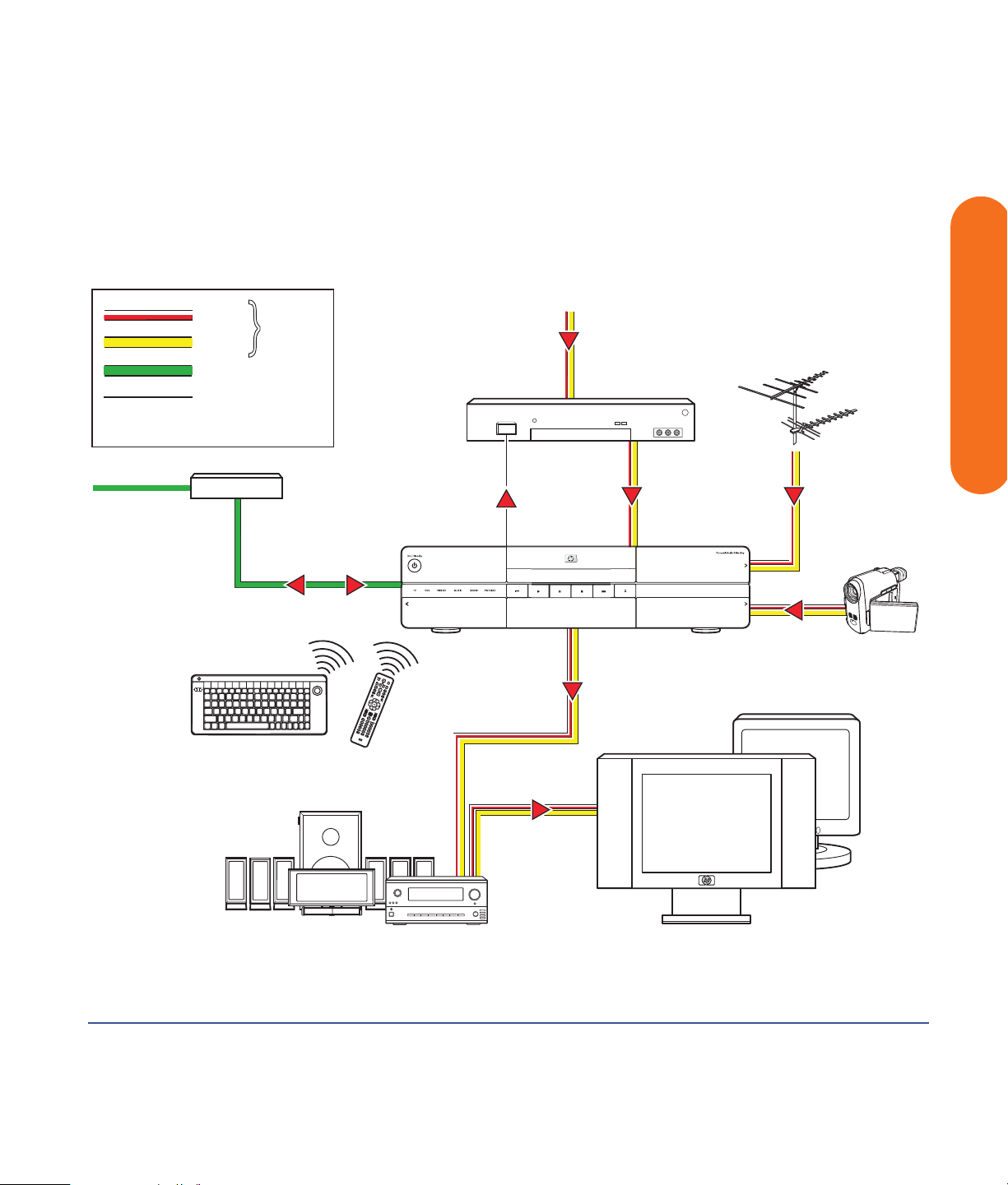
The following illustration shows the audio and video
signal routed from the satellite or cable receiver source to
the HP Digital Entertainment Center, then through an AV
receiver to your TV:
Internet
Download
TV Program
Guide
Audio
AV
Video
Network Data
Set-top-box Infrared
Transmitter
DSL/Cable Modem
or Wireless Router
Keyboard
Data
Remote
Control
TV Source
Infrared
Transmitter
AV In
Cable In
Cable Box or
Satellite Receiver
UHF
Antenna
TV
Source
In
HP Digital Entertainment Center
HP Digital Entertainment Center
AV Out
VHF
Antenna
Installation Overview
HDTV (ATSC)
and/or NTSC
Over-the-air
Digital Signal
Digital Video
Camcorder
Audio/Video flow
AV Receiver TV or Monitor
Installation Overview 21
Page 28
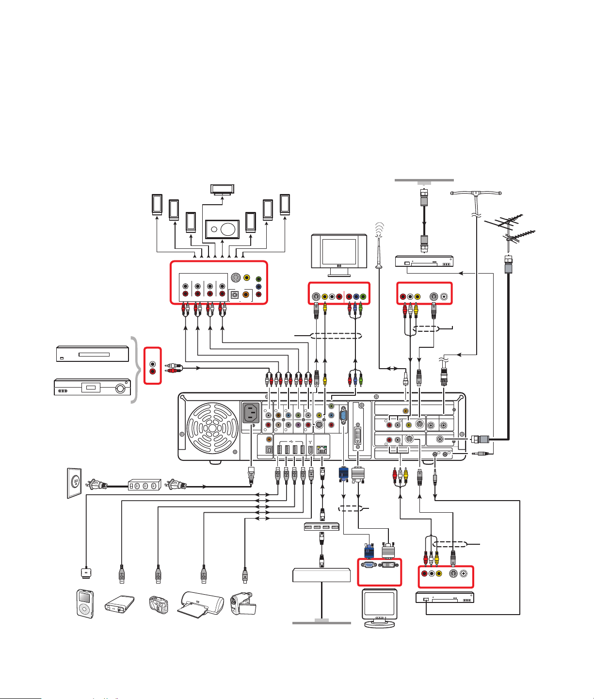
System Diagram
Back Panel
Surround
Note: 5.1 systems do not
include “Surr. Back”
connections.
CD
or Tape Player
AC
Wall Outlet
Surge Protector
Line Conditioner
Back
Left
OUT
Surround
Left
Front
Left
Subwoofer
AV RECEIVER IN
Audio In 7.1 Multichannel
Center
Surr. Back Surround
Sub
Center
Front
S-Video Video
Digital
Optical Coaxial
100-240V- 4/A 50/60Hz
Surround
Front
Right
Speakers
AC IN
Right
AUDIO IN
COAXIAL
OPTICAL
DIGITAL
Pr
Pb
Y
Choose
L
R
AUDIO
OUT
Surround
Back
Right
one
AUDIO 7.1 PRE-OUT
SURROUND
SURROUND CENTER
BACK
L L L
R R
WOOFER
HI SPEED USB 2.0 ETHERNET1394
S-video
FRONT
R
SUB
(Configurations may vary.)
Cable From Wall
WiFi
Antenna
S-video
WIRELESS LAN 802.11 b/g
REMOVABLE ANTENNA
L
VIDEO
S-VIDEO
S-VIDEOAUDIO
INFRARED TRANSMITTER OUT
OUT
ACTIVITY
LINK
CABLE/ANT. IN FM ANTENNA IN
Video
Component
VIDEO OUT
VIDEO
S-VIDEO COMPONENT
10/ 100/ 1000
TV IN
Y
Pb
Pr
VGA
DVI
DIGITAL VIDEO OUT
Composite
TV SOURCE 1 IN
R
AUDIO
TV SOURCE 2 IN
RL
Cable
or Satellite
Set-top box 1
Choose
one
Coaxial
75
Ω
DUAL
COAXIAL
TUNER
HDTV / SDTV ANT. IN
ATSC TUNER
12
FM Antenna
VHF
Antenna
Roof
Antenna
UHF
Antenna
Coaxial
iPod
Digital
PrinterExt. HDD
Camera
22 HP Digital Entertainment Center
Digital
Video Camcorder
Router/
Firewall/
Switch
DSL/Cable Modem
Wall
Internet
Choose
one
VGA
MONITOR
DVI
S-videoComposite
Choose
one
OUT
Cable
or Satellite
Set-top box 2
Note: Connect Set-top box 2 only
(optional)
Page 29
Front Panel
(Configurations may vary.)
The following illustration shows a typical HP Digital
Entertainment Center system front panel installation:
Choose
one
Analog
Video Camera
Power
On
On/Standby
S-VIDEO VIDEO AUDIO DV INL
S-VIDEO VIDEO AUDIO
S-video
FRONT INPUT
FRONT INPUT
Video
(Composite)
L
R
R
1394
KEYBOARD
CONNECT
1394
1394
DV IN
HI SPEED
USB 2.0
HP Personal
Media Drive
HP Digital Entertainment Center
SmartMedia / xD
CompactFlash I/II
SmartMedia / xD
CompactFlash I/II
Installation Overview
MMC / SD
MS / MS PRO
MMC / SD
MS / MS PRO
CD/DVD
Player/Recorder
HI SPEED
MIC INHEADPHONES
MIC INHEADPHONES
USB 2.0
Media Info
Display
USB 2.0
(x2)
Card Readers:
SmartMedia/xD,
MMC/SD,
CompactFlash I/II,
Microdrive
MS/MS Pro
Digital
Video
Camera
Digital
Camera
Installation Overview 23
Page 30
Installation Guidelines
To enhance the performance and extend the life of your
HP Digital Entertainment Center:
w
An open-back is required for adequate
cooling when installing your HP Digital
Entertainment Center in an AV cabinet.
■ Keep your HP Digital Entertainment Center in a
well-ventilated area, away from excessive light, heat,
or moisture.
■ Keep ventilation slots clear of obstructions such as
equipment or papers. The HP Digital Entertainment
Center automatically turns off if it gets too hot.
17 in
432 mm
On/Standby
HP Digital Entertainment Center
16.25 in
412.75 mm
4.5 in
114.3 mm
■ This product is heavy. Exercise caution when lifting
or moving.
■ Place your HP Digital Entertainment Center on a
stable, supported surface. Do not drop or place it
on an unstable surface.
■ Put your HP Digital Entertainment Center into
Standby when not in use. In Standby, the On/
Standby button is lit amber. Preset recordings only
start when the HP Digital Entertainment Center is on
or in Standby.
■ Adjust only those controls that are described in the
operating instructions.
■ Do not open your HP Digital Entertainment Center
cabinet or attempt to service this product yourself. If
your HP Digital Entertainment Center is not operating
properly or has been dropped or damaged, contact
your HP authorized dealer, reseller, or service
provider.
w
Leave slots and openings in the HP Digital
Entertainment Center cabinet open for
ventilation. These openings must not be
blocked or covered. Never push objects of
any kind into cabinet slots or other openings.
Choosing an HP Digital Entertainment
Center setup location
If you intend to connect your HP Digital Entertainment
Center to your TV, a set-top box, or a surround sound
system, HP recommends that you choose a clear working
area with easy access to the connectors of these devices.
If your TV is wall-mounted, make sure that you have
access to the rear ports on the TV before attempting to
connect it to the HP Digital Entertainment Center.
24 HP Digital Entertainment Center
Page 31

Placement and Ventilation Requirements
Cabinet Front
IMPORTANT: Use an open cabinet or shelves for best
operation of the HP Digital Entertainment Center. Do not
cover vents on top, back and sides of the unit.
If you choose to use a cabinet with front doors, you must
leave the doors open when the HP Digital Entertainment
Center is powered on.
.
w
Failure to follow these ventilation
requirements could cause the HP Digital
Entertainment Center to malfunction.
Installation Overview
Open cabinet (Actual home setup may vary.)
r
e
t
n
e
t C
n
e
m
n
i
ta
r
te
n
l E
ita
ig
D
P
H
Installation Overview 25
Page 32

Cabinet Back
The back of the AV cabinet should be open for best
operation.
19"W
Back View
minimum
Cabinet
6.5"H
minimum
minimum
HP Digital
Entertainment
Center
Wall Clearance
1"
If the AV cabinet has a back, the back must have a hole
behind the HP Digital Entertainment Center, for air
circulation, with a minimum open area of 19 inches
(48.3 cm) wide by 6.5 inches (16.5 cm) high.
See the following illustration.
2" minimum
1"
minimum
Note: These clearances are
required for proper
ventilation.
The HP Digital Entertainment Center back panel must be
at least 4 inches (10.2 cm) from the wall.
26 HP Digital Entertainment Center
Cabinet
HP Digital
Entertainment Center
Side View
4"
minimum
Wall
Back of
cabinet
Page 33

Basic Setup
Follow the steps in the Start Here booklet to set up the
HP Digital Entertainment Center.
Most of the hardware devices such as the monitor and
printer can be connected at the back panel of the
HP Digital Entertainment Center.
Some peripheral devices, such as a digital video camera,
can be plugged into the connectors on the back panel or
the front panel (behind lower doors) of the HP Digital
Entertainment Center.
Setting Up the HP Digital Entertainment Center
The basic steps to set up the HP Digital Entertainment
Center are in the Start Here booklet as follows. Your
system may be different. See the referenced sections for
detailed information on each step.
Before you begin:
■ Read “Safety Information” on page 17.
■ Read “Installation Guidelines” on page 24.
■ Refer to the Start Here booklet as a guide to connect
your HP Digital Entertainment Center.
Read the important safety information before
you install the HP Digital Entertainment
Center. See “Safety Information” on page 17.
Installation Overview
w
Required steps
1
Unpack the box contents.
a Take inventory. See “Inventory” on page 29.
Identify the items included with your HP Digital
Entertainment Center.
b Identify equipment you will need that is not
supplied.
c Place the HP Digital Entertainment Center where
you can easily reach the back panel.
2 Determine how you will connect the HP Digital
Entertainment Center to your system.
3 Connect the audio cables. See “Typical Audio
Connection” on page 38.
a Audio In (optional)
b Audio Out (to TV, AV receiver, speakers)
c Digital Audio Out
4 Connect the Video Out to the TV or display. See
“Typical Video Out Connections” on page 63.
Installation Overview 27
Page 34

5 Connect the TV Source 1 In and TV Source 2 In
cables. See “Typical TV Source Connections” on
page 78.
a Connect the Cable/Antenna In.
b Connect the Source 1 In audio/video cables to
cable TV box, digital cable box, or satellite
receiver 1.
11 Turn on all equipment, and then turn on the
HP Digital Entertainment Center. See “Starting the HP
Digital Entertainment Center for the First Time” on
page 128.
12 Complete the initial startup and registration. See
“Windows Welcome” on page 131.
a Follow the onscreen instructions.
c Connect the Source 2 In audio/video cables to
cable TV box, digital cable box, or satellite
receiver 2 (select models only).
d Connect the Infrared Transmitter 1 to cable TV
box, digital cable box, or satellite receiver 1.
e Connect the Infrared Transmitter 2 to cable TV
box, digital cable box, or satellite receiver 2
(select models only).
f Connect the HDTV Antenna In.
6 Connect the FM radio antenna. See “FM Radio
Antenna” on page 56.
7 Connect the Internet network cables. See “Typical
Network Connections” on page 116.
a DSL/cable modem to Internet (Ethernet)
b Wireless antenna
8 Pull the tab on the keyboard to activate the batteries.
See “Installing the Keyboard Batteries (Initial)” on
page 128.
9 Insert the remote control batteries. See “Installing the
Remote Control Batteries” on page 16.
10 Place the HP Digital Entertainment Center on a flat,
stable surface with the following clearances:
■ Top: 2 inches (5.08 cm)
■ Side: 1 inch (2.54 cm)
■ Back: Open cabinet
See “Safety Information” on page 17.
b Set up Media Center.
13 Optional step
(Recommended after basic setup)
Connect any additional rear panel devices.
a FireWire (IEEE 1394) device or digital video
camera. See “Peripheral Connection Overview”
on page 114.
b USB devices, such as printers or scanners
(up to 4). See “Peripheral Connection Overview”
on page 114.
14 Optional step
(Recommended after basic setup)
Connect front panel devices.
a FireWire (IEEE 1394) device or digital video
camera. See “Connecting Video Equipment” on
page 101.
b USB devices, such as printers or scanners
(up to 2). See “Peripheral Connection Overview”
on page 114.
c VCR or analog video camera. See “Connecting
Video Equipment” on page 101.
d Insert the removable hard disk drive (optional).
See “Connecting an HP Personal Media Drive”
on page 123.
Begin using your system. See the Media Center Edition
2005 Software Guide.
28 HP Digital Entertainment Center
Page 35

Inventory
HP Home Theater PC
System Recovery
W
in
d
o
w
s
®
X
P M
e
d
ia
C
e
n
te
r E
d
itio
n
2
0
0
4
S
u
p
p
o
r
t fo
r M
ic
ro
s
o
ft
p
r
o
d
u
c
ts
is
p
r
o
v
id
e
d
b
y
H
P
.
For distribution
only w
ith a
new
PC.
©
2
0
0
3
-2
0
0
4
H
e
w
le
tt-
P
a
ck
a
rd
D
e
v
e
lo
p
m
e
n
t
C
o
m
p
a
n
y, L
.P
.
P
o
rtio
ns
©
2
0
0
3
. M
ic
ro
so
ft
C
o
rp
o
ra
tio
n
.
A
ll rig
hts
re
se
r
v
e
d
.
P
ro
d
u
ct
o
f X
X
X
X
X
X
.
D
is
c
1
T
h
is
C
D
c
a
n
O
N
L
Y
b
e
u
s
e
d
w
ith
a
n
H
P
H
o
m
e
T
h
e
a
t
e
r
P
C
.
R
e
f
e
r t
o
th
e
p
rin
te
d
in
s
tru
c
tio
n
s
p
ro
v
id
e
d
w
ith
y
o
u
r
R
e
c
o
v
e
ry
C
D
s
.
H
P
1
2
3
4
-5
6
7
8
HP Home Theater PC
System Recovery
W
indows
®
XP Media Center Edition 2004
S
u
p
p
o
r
t
fo
r
M
ic
r
o
s
o
ft
p
r
o
d
u
c
ts
is
p
r
o
v
i
d
e
d
b
y
H
P
.
For distribution
only with a
new PC.
©
2
0
0
3
-2
0
0
4
H
e
w
le
tt-
P
a
c
ka
rd
D
e
ve
lo
p
m
e
n
t
C
o
m
p
a
n
y
, L.
P
.
P
o
rtio
n
s ©
2
0
0
3
. M
i
cr
o
s
o
ft
C
o
rp
o
ra
tio
n
.
A
ll rig
h
ts
r
e
s
e
rve
d
.
P
ro
d
u
c
t o
f X
X
X
X
X
X
.
Disc 1
T
h
is
C
D
c
a
n
O
N
L
Y
b
e
u
s
e
d
w
ith
a
n
H
P
H
o
m
e
T
h
e
a
te
r
P
C
.
R
e
f
e
r
to
th
e
p
r
i
n
te
d
in
s
tr
u
c
tio
n
s
p
r
o
v
id
e
d
w
i
th
y
o
u
r
R
e
c
o
v
e
r
y
C
D
s
.
H
P
1
2
3
4
-5
6
7
8
The following items are supplied with the HP Digital
Entertainment Center:
Name Picture Description
HP Digital
Entertainment
Center unit
HP Digital Entertainment Center
See “Functional Overview” on page 3.
Keyboard See “Keyboard” on page 10.
Remote control See “Remote Control” on page 14.
Cables See “Cables Included” on page 30.
FM antenna Antenna for FM radio, 75-ohm coaxial. See
“FM Radio Antenna” on page 56.
Wi-Fi antenna Antenna for Wireless LAN 802.11 b/g,
removable. See “Connecting the Wireless
H
P
H
o
m
e
T
h
S
e
y
a
ste
te
W
m
r P
i
n
R
d
C
o
e
w
®
c
s
o
X
v
P
e
M
ry
e
d
i
a
C
e
n
te
r
E
d
i
t
i
o
n
2
0
0
S
4
u
p
p
o
rt fo
p
r
M
ro
d
ic
u
ro
ct
so
s
is p
ft
b
© 2
y
H
r
o
0
v
P
03
ide
.
2004 Hewle
d
P
a
ckard De
tt-
Fo
velopme
Compa
r distribu
ny, L.P.
nt
Portion
o
s
nly
©2
tio
0
Co
0
w
n
3.
rporatio
M
ith a
i
cr
osoft
n.
All ri
ghts r
n
ew
eserved.
Prod
PC
uc
t
of
.
X
X
XXXX.
T
h
is
C
D
c
a
n
O
th
N
e
p
LY
r
b
in
te
e
u
d
se
in
d
str
w
u
ct
it
h
io
a
n
n
s
H
p
r
P
o
v
H
id
o
e
m
d
e
w
T
h
ith
e
a
y
te
H
o
r P
u
P
r
1
C
R
2
e
.
3
co
R
4
e
-5
ve
fe
6
ry
r
7
to
C
8
D
s
.
HP Digital Entertainment Center
Start Here
S
oftw
a
Documentation Printed documentation is included.
HP Digital Entertainment Center
Softw
HP Digital Entertainment Center
re
are G
G
u
id
e
uide
B
a
sic S
Connect your system
e
tu
p
Your connector locations and system components may vary.
to the back panel.
Network Antenna” on page 117.
Installation Overview
DVD recovery
Refer to the Warranty and Support Guide.
discs (2)
Batteries:
AA (6)
2 for remote (in package),
4 for keyboard (inside keyboard).
Installation Overview 29
Page 36

Cables Included
Your HP Digital Entertainment Center comes with the following cables.
Cable Name Description
Stereo RCA, red and white ends. Used for Audio Out.
DVI-D Digital video out. Connect to DVI-I or DVI-D input of the HDTV-
capable TV or monitor.
S-video Black. Used for Video Out.
Coaxial digital audio S/PDIF. Used for Digital Audio Out.
Infrared Transmitter
(2 with dual-tuner option)
Coaxial
(2 with dual-tuner option)
2 Way Splitter
Additional cables are sold separately. See “Optional
Cables Not Included” on page 31 for additional cables
that you may need.
Coaxial Splitter
(dual-tuner option)
AC Power
IR Blaster cable. Used for set-top boxes.
Used for TV source input from cable set-top boxes or antennas.
Used with coaxial cable for VHF and UHF antenna combinations.
Black 125V 10A.
30 HP Digital Entertainment Center
Page 37

Optional Cables Not Included
You might need the following extra cables
(these items are sold separately).
Cable Name Max quantity Description
Stereo and Video
(Composite)
Stereo 8 RCA: Red and white ends. Used for
Component video 1 RCA: Red, blue, and green ends. Used
S-video 4 Y/C, 4-pin. Plug cable into an S-video
Video (Composite) 4 RCA: Yellow end. Plug cable into an
S-video to composite
video adapter
VGA 1 15-pin, D-sub Analog. Used for monitor
4 RCA: Red, white, yellow ends. Used for
TV Source In connector.
Audio In/Out connectors.
for progressive scan component video.
connector such as S-video Video Out or
TV Source In connector.
RCA connector such as composite
Video Out or TV Source In connector.
1 Used with TV source input 2 composite
video input.
or HDTV capable TV.
Installation Overview
Optical digital audio 1 S/PDIF. Used for Digital Audio Out.
FireWire (IEEE 1394)
digital video in/out
USB 6 USB 2.0. Used for peripheral device
Ethernet RJ-45 1 Ethernet 10/100/1000. Used for
Coaxial Extra lengths Used for TV source input from cable
1
1
IEEE 1394 4-pin to 6-pin (back).
IEEE 1394 4-pin to 4-pin (front).
connectors.
broadband Internet connection.
set-top boxes or antennas.
Installation Overview 31
Page 38

Additional equipment
You must have the following items to set up and properly
operate your HP Digital Entertainment Center and system
(these items are sold separately):
■ Audio system equipment such as:
■ AV receiver with speakers
■ Powered speakers
■ TV speakers
■ Monitor speakers
■ Video equipment such as:
■ Monitor
■ TV
■ Video projector
■ Video output from cable/satellite box or antenna
■ UHF/VHF antenna for HDTV ATSC
Connecting cables
■ Broadband Internet equipment such as:
■ Cable/DSL modem (working connection required
for Media Center features, such as downloading
the Television Program Guide)
■ Wireless LAN 802.11 b/g network
■ Clean AC power (surge protector/line conditioner
recommended)
Additional equipment and cables are sold separately.
You may also need the following items (sold separately;
available at electronics stores) to fully set up your
HP Digital Entertainment Center, depending on your
system audio and video requirements:
■ Audio/Video/Network cables: See “Optional
Cables Not Included” on page 31.
■ Audio Y adapter(s), mini-plug to 2 RCA-plugs
(for powered speakers).
Observe the following guidelines:
■ Do not plug in the HP Digital Entertainment Center
until all connecting cables are installed.
■ Turn off power to all other equipment before
connecting cables.
32 HP Digital Entertainment Center
■ Connect cables firmly to avoid hum and noise.
■ Match the color codes, for instance: yellow — video,
white — left, red — right.
Page 39

Connecting Audio
The HP Digital Entertainment Center supports many
different audio options, sound connections, and speaker
configurations.
This chapter describes the most typical, and some
advanced, audio setup options for connecting Audio Out
and Audio In. To connect TV Source In audio and video,
see “Connecting TV Source In” on page 71.
Your system may have different components. Speakers,
AV receivers, and other equipment are sold separately.
Refer to the product documentation for these products.
Stereo
Chapter Contents:
“Audio Overview” on page 34
“Typical Audio Connection” on page 38
“TV Audio Connection” on page 39
“AV Receiver Audio Connection” on page 40
“Powered Speaker Audio Connection” on page 48
“Audio In Connections” on page 55
“FM Radio Antenna” on page 56
On/Standby
HP Digital Entertainment Center
Connecting Audio
HP Digital Entertainment Center
Connecting Audio 33
Page 40

Audio Overview
Audio Output Connectors
Digital Audio Out Audio Out
WIRELESS LAN 802.11 b/g
REMOVABLE ANTENNA
TV SOURCE 1 IN
L
R
AUDIO
VIDEO
TV SOURCE 2 IN
RL
INFRARED TRANSMITTER OUT
S-VIDEO
S-VIDEOAUDIO
ACTIVITY
LINK
CABLE/ANT. IN FM ANTENNA IN
DUAL
TUNER
HDTV / SDTV ANT. IN
ATSC TUNER
75
Ω
COAXIAL
12
100-240V- 4/A 50/60Hz
AC IN
AUDIO IN
L
R
COAXIAL
OPTICAL
DIGITAL
AUDIO 7.1 PRE-OUT
SURROUND
SURROUND CENTER
BACK
L L L
R R
AUDIO
HI SPEED USB 2.0 ETHERNET1394
OUT
SUB
WOOFER
FRONT
R
VIDEO OUT
VIDEO
S-VIDEO COMPONENT
10/ 100/ 1000
Y
Pb
Pr
DVI
VGA
DIGITAL VIDEO OUT
Connector Name Color Description Cable
SURROUND
BACK
L
R
SURROUND
L
R
CENTER
SUB
WOOFER
Surround
Back
Brown: Left
Beige: Right
Surround Blue: Left
Gray: Right
Center
Subwoofer
Green: Center
Purple: Subwoofer
Rear speakers in a multichannel audio
eight speaker system (7.1).
Side speakers in a multichannel audio
six or eight speaker system (4.1, 5.1,
6.1, 7.1).
Center speaker and subwoofer in a
multichannel audio system (5.1, 6.1, 7.1).
FRONT
L
Front White: Left
Red: Right
R
COAXIAL
OPTICAL
DIGITAL
COAXIAL
OPTICAL
DIGITAL
Coaxial
Digital Audio
AUDIO
OUT
Out
Optical
Digital Audio
AUDIO
OUT
Out
Orange Coaxial S/PDIF 5.1 only.
Gray Optical S/PDIF 5.1 only.
34 HP Digital Entertainment Center
Stereo speakers or front speakers in a
multichannel audio system
(2.0, 2.1, 4.1, 5.1, 6.1, 7.1).
See “Configuring Audio Output” on
page 139.
See “Configuring Audio Output” on
page 139.
Page 41

Sound Connector Jacks
The audio connectors are RCA-type jacks that connect
from the back of your HP Digital Entertainment Center to
a TV, powered speakers, or an AV receiver.
The HP Digital Entertainment Center has separate Audio
In connections (analog).
The HP Digital Entertainment Center has two Digital
Audio Out connections (S/PDIF) that are coaxial and
optical. Use analog Audio 7.1 Pre-out or Digital Audio
Out connectors, but not both. Use only one Digital Audio
Out connector at a time.
The HP Digital Entertainment Center does not have Digital
Audio In connections.
Speaker Types
A stereo speaker set is a left-right, two-channel speaker
system (sold separately).
A multichannel audio speaker system has a subwoofer,
left-right front, and left-right surround channels. The system
may also include a left-right surround back channel and a
center speaker. Surround back speakers are included in
more advanced 7.1 systems. A subwoofer provides
enhanced bass sounds.
The “.1” indicates a subwoofer. For example, 7.1
channels refer to an eight-speaker mode and uses two
front speakers (left-right), two side speakers (left-right),
two rear speakers (left-right), a center speaker, and a
subwoofer.
n
If your audio equipment has multiple input
and output connections, then it has front
panel input and output switches.
You must select the correct input and output
from the audio equipment front panel or
remote control to hear sound and see video.
Audio amplifiers
The HP Digital Entertainment Center does not supply an
amplified audio signal. You can connect the HP Digital
Entertainment Center to:
■ Passive speakers connected through a home audio
system. A home audio system does not require active
speakers because the receiver provides
amplification.
■ Active (powered) speakers directly. An active
speaker system must have its own power cord.
Connecting Audio
See “Speaker Configurations” on page 36 for more
information on speaker arrangements.
Connecting Audio 35
Page 42

Speaker Configurations
You can set up your HP Digital Entertainment Center for the following supported audio configurations:
Speaker
system
Home audio
system description Recommended arrangement See:
2 (stereo) Two speakers: Left
speaker, right speaker
2.1 Two speakers: Left
speaker, right speaker
One subwoofer
4.1 Two front speakers: Left
speaker, right speaker
Two side speakers:
surround left speaker,
surround right speaker
One subwoofer
Front left
speaker
Front left
speaker
Front left
speaker
Surround
left speaker
Subwoofer
Subwoofer
TV Display
TV Display
TV Display
Front right
speaker
Front right
speaker
Front right
speaker
Surround
right speaker
“2.0 Home Stereo
Installation” on
page 41
Or
“2.1 Powered
Speakers” on page 49
“2.1 Home Stereo
Installation” on
page 42
Or
“2.1 Powered
Speakers” on page 49
“4.1 Home Theater
Audio” on page 43
Or
“4.1 Powered
Speakers” on page 50
5.1 Two front speakers: Left
speaker, right speaker
Two side speakers:
surround left speaker,
surround right speaker
One center speaker
One subwoofer
36 HP Digital Entertainment Center
Front left
speaker
Surround
left speaker
Subwoofer
TV Display
Center
speaker
Front right
right speaker
speaker
Surround
“5.1 Home Theater
Audio” on page 44
Or
“5.1 Powered
Speakers” on page 51
Page 43

Speaker
system
Home audio
system description Recommended arrangement See:
6.1 Two front speakers: Left
speaker, right speaker
Two side speakers:
surround left speaker,
surround right speaker
One rear surround
back speaker
One center speaker
One subwoofer
7.1 Two front speakers: Left
speaker, right speaker
Subwoofer
TV Display
Center
speaker
If your 6.1 AV receiver
has only 5.1 (6) inputs,
see the following:
“5.1 Home Theater
Front left
speaker
Front right
speaker
Audio” on page 44
Or
“5.1 Powered
Speakers” on page 51
“7.1 Home Theater
Audio” on page 45
Center
speaker
Surround
right speaker
Surround
left speaker
Surround back speaker
Subwoofer
TV Display
Digital
audio 5.1
Two side speakers:
surround left speaker,
surround right speaker
Two rear speakers:
surround back left
speaker, surround back
right speaker
One center speaker
One subwoofer
Digital speakers or
digital input connector
on the audio system
Front left
speaker
Surround
left speaker
Surround back
left speaker
Subwoofer
Front left
speaker
Surround
left speaker
TV Display
Center
speaker
Front right
right speaker
Front right
speaker
Surround
right speaker
Surround back
right speaker
speaker
Surround
Or
“7.1 Powered
Speakers” on page 52
If your 7.1 AV receiver
has only five inputs, see
“5.1 Home Theater
Audio” on page 44
Connecting Audio
“Digital Home Theater
Audio” on page 46
Or
“Digital Powered
Speakers” on page 53
Connecting Audio 37
Page 44

Typical Audio Connection
Select the configuration that most closely matches your
home system.
You can set up your HP Digital Entertainment Center for
the following supported audio configurations:
Audio system Description See:
TV TV, monitor or display direct audio
connection with two speakers
AV receiver Home stereo or home theater audio system
with AV receiver and passive speakers
Powered speakers Audio system with active speakers “Powered Speaker Audio Connection”
FM FM Tuner In “FM Radio Antenna” on page 56
Headphones Speakers are muted on headphone
connection
Then see:
“Audio In Connections” on page 55
“Connecting Video Out” on page 57
“Configuring Audio” on page 136
“TV Audio Connection” on page 39
“AV Receiver Audio Connection” on
page 40
on page 48
“Connecting Headphones” on
page 136
38 HP Digital Entertainment Center
Page 45

TV Audio Connection
You can connect your TV, monitor, or display audio
directly to your HP Digital Entertainment Center for
two-speaker sound.
Connecting TV Audio
To connect a TV, monitor, or display audio directly:
■ Connect an RCA stereo cable (White: Left;
Red: Right) from the HP Digital Entertainment Center
back panel Audio Out connector to a TV Audio In
connector.
The following diagram shows a basic TV audio installation:
TV
AUDIO IN
If your TV has multiple inputs, you can use your TV as a
switch for audio and video.
Refer to the Start Here booklet that came with the
HP Digital Entertainment Center.
For additional information on connecting the speakers,
refer to the documentation that came with your speakers
and AV receiver.
Basic TV audio setup (2.0)
100-240V- 4/A 50/60Hz
AC IN
AUDIO IN
L
R
COAXIAL
OPTICAL
DIGITAL
AUDIO 7.1 PRE-OUT
SURROUND
SURROUND CENTER
BACK
L L L
R R R
AUDIO
HI SPEED USB 2.0 ETHERNET1394
OUT
SUB
WOOFER
FRONT
VIDEO OUT
VIDEO
S-VIDEO COMPONENT
10/ 100/ 1000
Y
Pb
Pr
VGA
DVI
DIGITAL VIDEO OUT
WIRELESS LAN 802.11 b/g
REMOVABLE ANTENNA
TV SOURCE 1 IN
L
R
AUDIO
VIDEO
TV SOURCE 2 IN
RL
INFRARED TRANSMITTER OUT
ACTIVITY
LINK
CABLE/ANT. IN FM ANTENNA IN
75
Ω
DUAL
TUNER
HDTV / SDTV ANT. IN
ATSC TUNER
COAXIAL
12
S-VIDEO
S-VIDEOAUDIO
Connecting Audio 39
Connecting Audio
Page 46

AV Receiver Audio Connection
You can connect your HP Digital Entertainment Center to
your home stereo or home theater multichannel AV
receivers or audio amplifiers using your existing
speakers.
n
You can also connect video through your AV
receiver or to your TV directly.
AV Receiver Equipment Overview
Select the configuration that most closely
matches your home system. See:
“2.0 Home Stereo Installation” on page 41
“2.1 Home Stereo Installation” on page 42
“4.1 Home Theater Audio” on page 43
“5.1 Home Theater Audio” on page 44
“7.1 Home Theater Audio” on page 45
You can also use a digital connection.
“Digital Home Theater Audio” on page 46
You can connect audio and video from the HP Digital
Entertainment Center, through an AV receiver, to the TV
input.
Use this method to connect AV receivers or audio-only
home receiver/amplifiers that have standard RCA-type
input connectors. You may have to select a front
panel button on your AV receiver to switch
audio inputs to hear sound.
40 HP Digital Entertainment Center
Use the 2.1 configuration for multichannel AV receivers
that have only left and right audio inputs.
Connecting a home stereo to an HP Digital Entertainment
Center typically requires audio cables that are long
enough to connect from the HP Digital Entertainment
Center to the stereo or AV receiver. Additional cables are
sold separately.
Page 47

2.0 Home Stereo Installation
The following diagram shows a typical two-channel (2.0)
speaker installation that uses passive stereo speakers
connected through a home stereo standard left and right
input.
AUDIO IN
LR
2 Channel
AV Receiver
100-240V- 4/A 50/60Hz
AC IN
AUDIO IN
COAXIAL
OPTICAL
DIGITAL
SURROUND
BACK
L
L L L
R
R R
AUDIO
OUT
AUDIO 7.1 PRE-OUT
SURROUND CENTER
HI SPEED USB 2.0 ETHERNET1394
SUB
WOOFER
FRONT
R
This is only a suggested configuration. Your system may
be different.
AV receiver/amplifier audio input connectors may be
labeled CD, DVD, or DVD In.
VIDEO OUT
VIDEO
S-VIDEO COMPONENT
10/ 100/ 1000
Y
Pb
Pr
DVI
VGA
DIGITAL VIDEO OUT
WIRELESS LAN 802.11 b/g
REMOVABLE ANTENNA
TV SOURCE 1 IN
R
L
AUDIO
VIDEO
TV SOURCE 2 IN
RL
INFRARED TRANSMITTER OUT
S-VIDEO
S-VIDEOAUDIO
ACTIVITY
LINK
CABLE/ANT. IN FM ANTENNA IN
DUAL
TUNER
HDTV / SDTV ANT. IN
ATSC TUNER
75
COAXIAL
12
Ω
Connecting Audio
2.0 audio system connection
Connecting Audio 41
Page 48

2.1 Home Stereo Installation
The following diagram shows a typical two-channel (2.1)
speaker installation that uses passive stereo speakers
connected through a home stereo standard left and right
input.
This is only a suggested configuration. Your system may
be different. Use this configuration for multichannel AV
receivers that only left and right audio inputs.
AV receiver/amplifier audio input connectors may be
labeled CD, DVD, or DVD In.
AUDIO IN
LR
2.1 Channel
AV Receiver
Some AV receivers generate the subwoofer
output without a subwoofer input; in this
case, you do not need to connect the
subwoofer output from the HP Digital
Entertainment Center. Refer to your AV
receiver product documentation.
n
100-240V- 4/A 50/60Hz
AC IN
AUDIO IN
COAXIAL
OPTICAL
DIGITAL
SURROUND
BACK
L
L L L
R
R R
AUDIO
OUT
AUDIO 7.1 PRE-OUT
SURROUND CENTER
WOOFER
HI SPEED USB 2.0 ETHERNET1394
2.1 multichannel audio system connection
42 HP Digital Entertainment Center
VIDEO OUT
FRONT
VIDEO
R
SUB
S-VIDEO COMPONENT
10/ 100/ 1000
Y
Pb
Pr
DVI
VGA
DIGITAL VIDEO OUT
WIRELESS LAN 802.11 b/g
REMOVABLE ANTENNA
TV SOURCE 1 IN
L
R
AUDIO
TV SOURCE 2 IN
RL
VIDEO
INFRARED TRANSMITTER OUT
S-VIDEO
S-VIDEOAUDIO
ACTIVITY
LINK
CABLE/ANT. IN FM ANTENNA IN
DUAL
TUNER
HDTV / SDTV ANT. IN
ATSC TUNER
75
Ω
COAXIAL
12
Page 49

4.1 Home Theater Audio
The following diagram shows a typical advanced home
theater audio four-channel 4/4.1 speaker installation that
requires multichannel inputs on a receiver/amplifier.
This is only a suggested configuration. Your system may
be different.
AV receiver/amplifier audio input connectors may be
labeled Surround, 4.1 or 4 Channel inputs, CD, DVD,
or DVD In.
AUDIO IN
100-240V- 4/A 50/60Hz
AC IN
AUDIO IN
COAXIAL
OPTICAL
DIGITAL
SURROUND
BACK
L
L L L
R
R R
AUDIO
OUT
AUDIO 7.1 PRE-OUT
SURROUND CENTER
HI SPEED USB 2.0 ETHERNET1394
SUB
WOOFER
FRONT
R
n
Some AV receivers generate the subwoofer
output without a subwoofer input; in this
case, you do not need to connect the
subwoofer output from the HP Digital
Entertainment Center. Refer to your AV
receiver product documentation.
4.1 Channel AV Receiver
VIDEO OUT
VIDEO
S-VIDEO COMPONENT
10/ 100/ 1000
Y
Pb
Pr
DVI
VGA
DIGITAL VIDEO OUT
WIRELESS LAN 802.11 b/g
REMOVABLE ANTENNA
TV SOURCE 1 IN
R
L
AUDIO
TV SOURCE 2 IN
RL
VIDEO
INFRARED TRANSMITTER OUT
S-VIDEO
S-VIDEOAUDIO
ACTIVITY
LINK
CABLE/ANT. IN FM ANTENNA IN
HDTV / SDTV ANT. IN
DUAL
TUNER
ATSC TUNER
75Ω
COAXIAL
12
Connecting Audio
4.1 multichannel audio system connection
Connecting Audio 43
Page 50

5.1 Home Theater Audio
The following diagram shows a typical advanced home
theater audio six-channel (5.1) speaker installation that
requires multichannel inputs on an AV receiver.
This is only a suggested configuration. Your system may
be different. Use this configuration for 6.1 and 7.1 AV
receivers that upmix the rear speaker(s). Use the 2.1
configuration for 5.1 AV receivers that have only left and
right inputs. Refer to your AV receiver product
documentation.
AV receiver audio input connectors may be labeled
Surround, 5.1 or 6 Channel Inputs, DVD, Ext. In, or
Multichannel Inputs.
AUDIO IN
Both Media Center speaker settings and DVD
audio settings must be changed for proper
audio setup. Go to “Configuring Audio
Output” on page 139 and note your speaker
configuration choice for later software setup
steps.
n
5.1 Channel AV Receiver
100-240V- 4/A 50/60Hz
AC IN
AUDIO IN
R
COAXIAL
OPTICAL
DIGITAL
SURROUND
BACK
L
L L L
R R R
AUDIO
HI SPEED USB 2.0 ETHERNET1394
OUT
AUDIO 7.1 PRE-OUT
SURROUND CENTER
WOOFER
SUB
5.1 multichannel audio system connection
44 HP Digital Entertainment Center
FRONT
VIDEO OUT
VIDEO
S-VIDEO COMPONENT
10/ 100/ 1000
Y
Pb
Pr
VGA
DVI
DIGITAL VIDEO OUT
WIRELESS LAN 802.11 b/g
REMOVABLE ANTENNA
TV SOURCE 1 IN
R
L
AUDIO
TV SOURCE 2 IN
RL
VIDEO
INFRARED TRANSMITTER OUT
S-VIDEO
S-VIDEOAUDIO
ACTIVITY
LINK
CABLE/ANT. IN FM ANTENNA IN
DUAL
TUNER
HDTV / SDTV ANT. IN
ATSC TUNER
75
COAXIAL
12
Ω
Page 51

7.1 Home Theater Audio
The following diagram shows a typical advanced home
theater audio eight-channel (7.1) speaker installation that
requires multichannel inputs on an AV receiver.
This is only a suggested configuration. Your system may
be different. If your AV receiver supports 7.1 and has
only 5.1 inputs, see “5.1 Home Theater Audio” on
page 44.
n
Some AV receivers can generate (upmix) the
7.1 audio with 5.1 channels. Refer to your AV
receiver product documentation.
AUDIO IN
Surr. Back Surround
Center
Sub Front
AV receiver audio input connectors may be labeled
Surround, 7.1 or 8 Channel inputs, DVD, Ext. In, or
Multichannel Inputs.
n
Both Media Center speaker settings and DVD
audio settings must be changed for proper
audio setup. Go to “Configuring Audio
Output” on page 139 and note your speaker
configuration choice for later software setup
steps.
7.1 Channel AV Receiver
Connecting Audio
100-240V- 4/A 50/60Hz
AC IN
AUDIO IN
COAXIAL
OPTICAL
DIGITAL
SURROUND
BACK
L
L L L
R
R R
AUDIO
OUT
AUDIO 7.1 PRE-OUT
SURROUND CENTER
SUB
WOOFER
HI SPEED USB 2.0 ETHERNET1394
7.1 multichannel audio system connection
FRONT
R
VIDEO OUT
VIDEO
S-VIDEO COMPONENT
10/ 100/ 1000
Y
Pb
Pr
VGA
DIGITAL VIDEO OUT
WIRELESS LAN 802.11 b/g
REMOVABLE ANTENNA
DVI
TV SOURCE 1 IN
L
R
AUDIO
TV SOURCE 2 IN
RL
INFRARED TRANSMITTER OUT
VIDEO
S-VIDEO
S-VIDEOAUDIO
ACTIVITY
LINK
CABLE/ANT. IN FM ANTENNA IN
DUAL
TUNER
HDTV / SDTV ANT. IN
ATSC TUNER
75
COAXIAL
12
Ω
Connecting Audio 45
Page 52

Digital Home Theater Audio
The HP Digital Entertainment Center supports digital
audio output.
■ For TV and music: two-channel stereo. (Your AV
receiver may separate the audio signal into multiple
channels.)
■ For DVD playback: the multiple channel Dolby
Digital 5.1 or DTS Digital encoded audio signal
passes to your AV receiver for decoding. Refer to
your AV receiver product documentation.
You can connect either the coaxial or the optical digital
audio cable, depending on your system. If you have both
cables, connect only one cable. Do not connect analog
multichannel speaker outputs if you connect the digital
output.
■ Insert optical cords straight in until they click into
place.
■ Do not bend or tie optical cords.
To connect digital audio from your HP Digital
Entertainment Center to an AV receiver:
1 Connect the Digital Audio Out connector on the back
panel of your HP Digital Entertainment Center to the
Digital Input (S/PDIF) on your AV receiver or digital
audio system.
The following diagram shows a typical advanced home
theater audio six-channel 5.1 speaker installation that
requires a digital input on an AV receiver. This is only a
suggested configuration. Your system may be different,
such as having more speakers.
n
Both Media Center speaker settings and DVD
audio settings must be changed for proper
audio setup. Go to “Configuring Audio
Output” on page 139 and note your speaker
configuration choice for later software setup
steps.
2 Select the AV receiver input.
3 Use the AV receiver to adjust the volume.
n
Some AV receivers can generate (upmix) the
7.1 audio with 5.1 channels. Refer to your AV
receiver product documentation.
46 HP Digital Entertainment Center
Page 53

DIGITAL
AUDIO IN
Coaxial Optical
Recommended
for best digital
audio experience
5.1 Channel AV Receiver
Choose one
100-240V- 4/A 50/60Hz
AC IN
AUDIO IN
R
COAXIAL
OPTICAL
DIGITAL
SURROUND
BACK
L
L L L
R R
AUDIO
OUT
AUDIO 7.1 PRE-OUT
SURROUND CENTER
HI SPEED USB 2.0 ETHERNET1394
SUB
WOOFER
FRONT
R
VIDEO
S-VIDEO COMPONENT
10/ 100/ 1000
Digital Audio Out
Digital 5.1 multichannel audio system connection
VIDEO OUT
Y
Pb
Pr
VGA
DVI
DIGITAL VIDEO OUT
WIRELESS LAN 802.11 b/g
REMOVABLE ANTENNA
TV SOURCE 1 IN
L
R
AUDIO
TV SOURCE 2 IN
RL
VIDEO
INFRARED TRANSMITTER OUT
S-VIDEO
S-VIDEOAUDIO
ACTIVITY
LINK
CABLE/ANT. IN FM ANTENNA IN
DUAL
TUNER
HDTV / SDTV ANT. IN
ATSC TUNER
75
Ω
COAXIAL
12
Connecting Audio
Connecting Audio 47
Page 54

Powered Speaker Audio Connection
You can connect active (powered) speakers directly to
your HP Digital Entertainment Center. An active speaker
system must have its own power cord.
You may need Y adapter cables (sold separately).
Y adapter cables
The HP Digital Entertainment Center has RCA-type output
connectors. You may need to connect Y adapter cables
between your HP Digital Entertainment Center analog
audio output and your powered speaker inputs. You can
also use them for audio inputs depending on your
equipment.
Use Y adapter cables with one female 1/8 inch (3.5 mm)
stereo mini-jack on one end and two male RCA
connectors on the other end. These cables are sold
separately.
Select the configuration that most closely
matches your home system. See:
“2.1 Powered Speakers” on page 49
“4.1 Powered Speakers” on page 50
“5.1 Powered Speakers” on page 51
“7.1 Powered Speakers” on page 52
You can also use a digital connection.
“Digital Powered Speakers” on page 53
Select the cable that most closely matches
your home system:
2.1 speaker system: 1 Y adapter cable
4.1 speaker system: 2 Y adapter cables
5.1 speaker system: 3 Y adapter cables
7.1 speaker system: 4 Y adapter cables
The number of Y adapter cables you need to connect to
your home stereo system depends on the number of
speakers you install.
48 HP Digital Entertainment Center
n
Y adapter cables and extension cables are
sold separately.
Page 55

2.1 Powered Speakers
To connect simple left/right stereo (2.0) active speakers:
Or
To connect two speakers and a subwoofer for 2.1
speaker output:
1 Connect the RCA connector end of the Y adapter
cable (sold separately) to the Front Right and Front
Left Audio Out connectors on the back of your
HP Digital Entertainment Center.
100-240V- 4/A 50/60Hz
AC IN
AUDIO IN
R
COAXIAL
OPTICAL
DIGITAL
SURROUND
BACK
L
L L L
R R
AUDIO
OUT
AUDIO 7.1 PRE-OUT
SURROUND CENTER
HI SPEED USB 2.0 ETHERNET1394
SUB
WOOFER
FRONT
R
2 Connect the female 1/8 inch (3.5 mm) mini-jack end
of the Y adapter cable to the Audio Line In cable of
the speaker amplifier.
3 Plug in the speaker system power. Refer to the
speaker documentation.
4 Turn on the speaker system.
Subwoofer
AC
VIDEO OUT
VIDEO
S-VIDEO COMPONENT
10/ 100/ 1000
Y
Pb
Pr
DVI
VGA
DIGITAL VIDEO OUT
WIRELESS LAN 802.11 b/g
REMOVABLE ANTENNA
TV SOURCE 1 IN
L
R
AUDIO
TV SOURCE 2 IN
RL
VIDEO
INFRARED TRANSMITTER OUT
S-VIDEO
S-VIDEOAUDIO
ACTIVITY
LINK
CABLE/ANT. IN FM ANTENNA IN
HDTV / SDTV ANT. IN
DUAL
TUNER
ATSC TUNER
75
COAXIAL
12
Connecting Audio
Ω
2.1 powered speaker installation
Connecting Audio 49
Page 56

4.1 Powered Speakers
To connect two front speakers, two surround speakers,
and a subwoofer for four-channel (4.1 speaker) output:
1 Connect the RCA connector end of the Y adapter
cables (sold separately) to the Audio Out connectors
Front Right, Front Left, Surround Right, and Surround
Left on the back of your HP Digital Entertainment
Center.
AC
2 Connect the female 1/8 inch (3.5 mm) mini-jack end
of the Y adapters to the Audio Line In cables of the
speaker amplifier.
3 Plug in the speaker system power. Refer to the
speaker documentation.
4 Turn on the speaker system.
Subwoofer
AUDIO IN
L
100-240V- 4/A 50/60Hz
AC IN
COAXIAL
OPTICAL
DIGITAL
R
AUDIO
OUT
4.1 powered speaker installation
50 HP Digital Entertainment Center
AUDIO 7.1 PRE-OUT
SURROUND
SURROUND CENTER
BACK
L L L
R R R
SUB
WOOFER
HI SPEED USB 2.0 ETHERNET1394
FRONT
VIDEO OUT
VIDEO
S-VIDEO COMPONENT
10/ 100/ 1000
Y
Pb
Pr
VGA
DIGITAL VIDEO OUT
WIRELESS LAN 802.11 b/g
REMOVABLE ANTENNA
DVI
TV SOURCE 1 IN
L
R
AUDIO
TV SOURCE 2 IN
RL
INFRARED TRANSMITTER OUT
VIDEO
S-VIDEO
S-VIDEOAUDIO
ACTIVITY
LINK
CABLE/ANT. IN FM ANTENNA IN
DUAL
TUNER
HDTV / SDTV ANT. IN
ATSC TUNER
75Ω
COAXIAL
12
Page 57

5.1 Powered Speakers
To connect two front speakers, two surround speakers, a
center speaker, and a subwoofer for six-channel
(5.1 speaker) output:
1 Connect the RCA connector end of the Y adapter
cables (sold separately) to the Audio Out connectors
Front Right, Front Left, Surround Right, Surround Left,
and Center on the back of your HP Digital
Entertainment Center.
AC
2 Connect the female 1/8 inch (3.5 mm) mini-jack end
of the Y adapters to the Audio Line In cables of the
speaker amplifier.
3 Plug in the speaker system power. Refer to the
speaker documentation.
4 Turn on the speaker system.
Subwoofer
Center Speaker
Connecting Audio
100-240V- 4/A 50/60Hz
AC IN
AUDIO IN
COAXIAL
OPTICAL
DIGITAL
SURROUND
BACK
L
L L L
R
R R
AUDIO
OUT
AUDIO 7.1 PRE-OUT
SURROUND CENTER
HI SPEED USB 2.0 ETHERNET1394
Typical 5.1 powered speaker installation
SUB
WOOFER
FRONT
R
VIDEO OUT
VIDEO
S-VIDEO COMPONENT
10/ 100/ 1000
Y
Pb
Pr
VGA
DIGITAL VIDEO OUT
WIRELESS LAN 802.11 b/g
REMOVABLE ANTENNA
DVI
TV SOURCE 1 IN
L
R
AUDIO
TV SOURCE 2 IN
RL
INFRARED TRANSMITTER OUT
VIDEO
S-VIDEO
S-VIDEOAUDIO
ACTIVITY
LINK
CABLE/ANT. IN FM ANTENNA IN
DUAL
TUNER
HDTV / SDTV ANT. IN
ATSC TUNER
75
COAXIAL
12
Ω
Connecting Audio 51
Page 58

7.1 Powered Speakers
You can install a 7.1 audio system to your HP Digital
Entertainment Center.
To connect two front speakers, two surround speakers,
two surround back speakers, a center speaker, and a
subwoofer for eight-channel (7.1 speaker) output:
1 Connect the RCA connector end of the Y adapter
cables to the Audio Out connectors Front Right, Front
Left, Center, Surround Right, Surround Left, Surround
Back on the back of your HP Digital Entertainment
Center.
2 Connect the female 1/8 inch (3.5 mm) mini-jack end
of the Y adapters to the Audio Line In cables of the
speaker amplifier.
AC
3 Plug in the speaker system power. Refer to the
speaker documentation.
4 Turn on the speaker system.
n
Some powered speakers can generate
(upmix) the 7.1 audio with 5.1 input
channels. Refer to your product
documentation.
Subwoofer
Center Speaker
AUDIO IN
AUDIO 7.1 PRE-OUT
SURROUND
SURROUND CENTER
BACK
L
L L L
100-240V- 4/A 50/60Hz
AC IN
COAXIAL
OPTICAL
DIGITAL
R
R R
AUDIO
OUT
HI SPEED USB 2.0 ETHERNET1394
Typical 7.1 powered speaker installation
52 HP Digital Entertainment Center
SUB
WOOFER
FRONT
R
VIDEO OUT
VIDEO
S-VIDEO COMPONENT
10/ 100/ 1000
Y
Pb
Pr
VGA
DVI
DIGITAL VIDEO OUT
WIRELESS LAN 802.11 b/g
REMOVABLE ANTENNA
TV SOURCE 1 IN
R
L
AUDIO
VIDEO
TV SOURCE 2 IN
RL
INFRARED TRANSMITTER OUT
S-VIDEO
S-VIDEOAUDIO
ACTIVITY
LINK
CABLE/ANT. IN FM ANTENNA IN
DUAL
TUNER
HDTV / SDTV ANT. IN
ATSC TUNER
75
COAXIAL
Ω
12
Page 59

Digital Powered Speakers
You can install a digital audio system with up to two front
speakers, two surround speakers, two surround back
speakers, a center speaker, and a subwoofer to your
HP Digital Entertainment Center.
Do not connect analog multichannel speaker outputs if
you connect the digital output.
You can connect either the coaxial or optical digital audio
cable, depending on your system. If you have both
cables, connect one cable only.
■ Insert optical cords straight in until they click into
place.
■ Do not bend or tie optical cords.
To connect six-channel (5.1 speaker) digital output to a speaker digital input:
Some powered speakers can generate
(upmix) the 7.1 audio with 5.1 input
channels. Refer to your product
documentation.
n
1 Connect a digital audio coaxial or optical cable to
a Digital Audio Out connector on the back of your
HP Digital Entertainment Center.
2 Connect the digital audio coaxial or optical cable to
the speakers.
DIGITAL
AUDIO IN
Coaxial Optical
Choose one
AUDIO IN
AUDIO 7.1 PRE-OUT
SURROUND
SURROUND CENTER
BACK
L
L L L
100-240V- 4/A 50/60Hz
R
COAXIAL
OPTICAL
DIGITAL
R R
AUDIO
OUT
AC IN
Digital Audio Out
Digital powered speaker installation (5.1 shown)
FRONT
R
SUB
WOOFER
HI SPEED USB 2.0 ETHERNET1394
VIDEO
S-VIDEO COMPONENT
10/ 100/ 1000
3 Plug in the speaker system power. Refer to the
speaker documentation.
4 Turn on the speaker system.
VIDEO OUT
Y
Pb
Pr
DVI
VGA
DIGITAL VIDEO OUT
WIRELESS LAN 802.11 b/g
REMOVABLE ANTENNA
TV SOURCE 1 IN
L
R
AUDIO
VIDEO
TV SOURCE 2 IN
RL
INFRARED TRANSMITTER OUT
S-VIDEO
S-VIDEOAUDIO
ACTIVITY
LINK
CABLE/ANT. IN FM ANTENNA IN
DUAL
TUNER
HDTV / SDTV ANT. IN
ATSC TUNER
75
Ω
COAXIAL
12
Connecting Audio
Connecting Audio 53
Page 60

Monitor Speakers
You can connect powered monitor speakers directly to
your HP Digital Entertainment Center.
You may need Y adapter cables.
You can:
■ Connect simple left/right stereo 2.0 powered
monitor speakers.
Or
■ Connect two powered speakers and a subwoofer for
2.1 monitor speaker output.
n
Monitor speaker configurations and
connections may vary. Your system may be
different.
Monitor
Audio Out
AUDIO IN
AUDIO 7.1 PRE-OUT
SURROUND
SURROUND CENTER
BACK
L
L L L
100-240V- 4/A 50/60Hz
AC IN
COAXIAL
OPTICAL
DIGITAL
R
AUDIO
OUT
R R
HI SPEED USB 2.0 ETHERNET1394
Monitor speaker installation (2.0 shown)
54 HP Digital Entertainment Center
SUB
WOOFER
FRONT
R
VIDEO OUT
VIDEO
S-VIDEO COMPONENT
10/ 100/ 1000
Y
Pb
Pr
VGA
DVI
DIGITAL VIDEO OUT
WIRELESS LAN 802.11 b/g
REMOVABLE ANTENNA
TV SOURCE 1 IN
R
L
AUDIO
VIDEO
TV SOURCE 2 IN
RL
INFRARED TRANSMITTER OUT
S-VIDEO
S-VIDEOAUDIO
ACTIVITY
LINK
CABLE/ANT. IN FM ANTENNA IN
DUAL
TUNER
HDTV / SDTV ANT. IN
ATSC TUNER
75
COAXIAL
Ω
12
Page 61
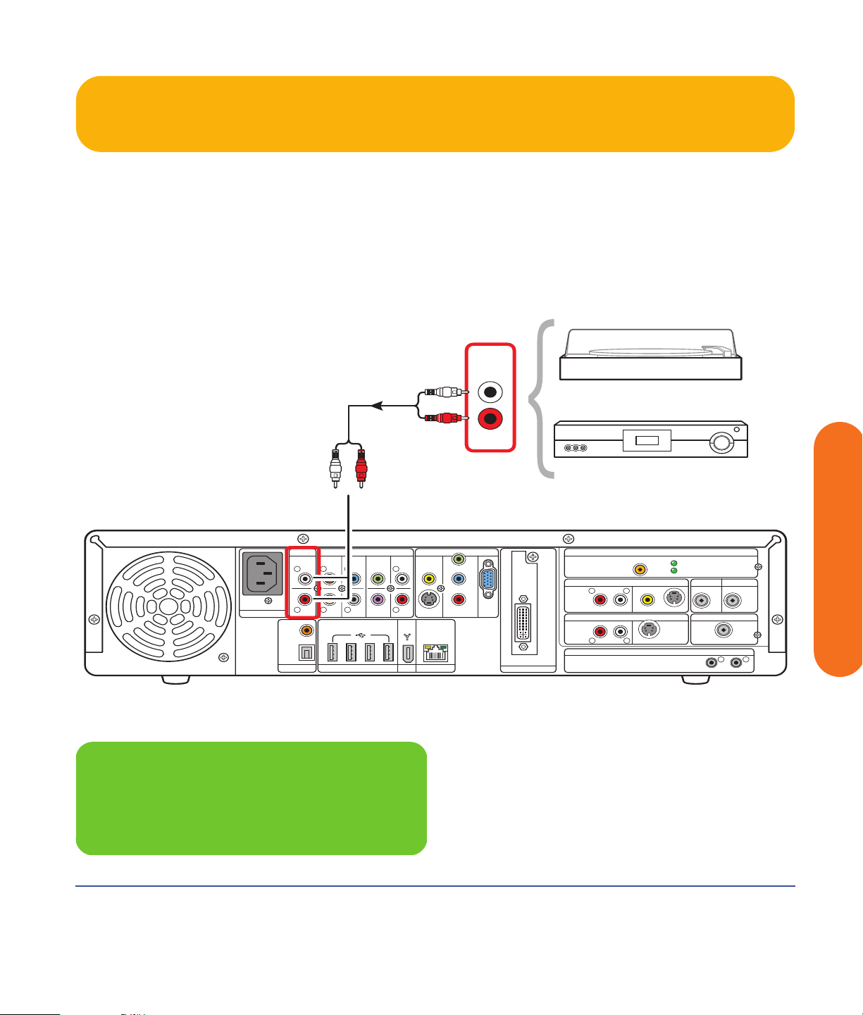
Audio In Connections
You can connect your existing home stereo or home
theater audio equipment, such as a tape player or
turntable, to your HP Digital Entertainment Center using
the Audio In stereo connectors on the back panel.
Audio In
100-240V- 4/A 50/60Hz
AC IN
AUDIO IN
COAXIAL
OPTICAL
DIGITAL
SURROUND
BACK
L
L L L
R
R R
AUDIO
OUT
AUDIO 7.1 PRE-OUT
SURROUND CENTER
HI SPEED USB 2.0 ETHERNET1394
SUB
WOOFER
FRONT
R
The Audio In connection can be used in conjunction with
sound recording software (application software sold
separately) to record audio from other external
equipment.
The following diagram shows a typical Audio In stereo
connection. This is only a suggested configuration. Your
system may be different.
Turntable
OUT
or Tape Player
VIDEO OUT
VIDEO
S-VIDEO COMPONENT
10/ 100/ 1000
Y
Pb
Pr
DVI
VGA
DIGITAL VIDEO OUT
WIRELESS LAN 802.11 b/g
REMOVABLE ANTENNA
TV SOURCE 1 IN
L
R
AUDIO
TV SOURCE 2 IN
RL
INFRARED TRANSMITTER OUT
VIDEO
S-VIDEO
S-VIDEOAUDIO
ACTIVITY
LINK
CABLE/ANT. IN FM ANTENNA IN
DUAL
TUNER
HDTV / SDTV ANT. IN
ATSC TUNER
75
COAXIAL
12
Ω
Connecting Audio
Audio In stereo connection
n
A turntable might require special phono
inputs through a mixer.
Connecting Audio 55
Page 62

FM Radio Antenna
-
The HP Digital Entertainment Center includes an FM radio
tuner.
To connect the FM radio antenna:
1 Plug the FM radio antenna cable into the FM (Tuner)
In connector on the back panel (75-Ohm Coaxial).
2 You may want to extend the ends of the cable to
improve your FM radio signal reception.
802.11 b/g
ENNA
ACTIVITY
LINK
802.11 b/g
NA
ACTIVITY
CABLE/ANT. IN FM ANTENNA IN
LINK
CABLE/ANT. IN FM ANTENNA IN
DUAL
75
Ω
COAXIAL
O S-VIDEO
S-VIDEO
S-VIDEO
ANSMITTER OUT
VIDEO
SMITTER OUT
TUNER
HDTV / SDTV ANT. IN
HDTV / SDTV ANT. IN
DUAL
TUNER
ATSC TUNER
ATSC TUNER
75
COAXIAL
12
12
Ω
Choose one
100-240V- 4/A 50/60Hz
AC IN
AUDIO IN
COAXIAL
OPTICAL
DIGITAL
SURROUND
BACK
L
L L L
R
R R
AUDIO
OUT
AUDIO 7.1 PRE-OUT
SURROUND CENTER
HI SPEED USB 2.0 ETHERNET1394
SUB
WOOFER
FRONT
R
S-VIDEO COMPONENT
10/ 100/ 1000
VIDEO OUT
VIDEO
The following diagram shows typical FM antenna
connections:
■ Indoor antenna
Or
■ Rooftop antenna (sold separately)
This is only a suggested configuration. Your system may
be different.
FM AntennaFM Radio Roof Antenna
WIRELESS LAN 802.11 b/g
Y
Pb
Pr
DVI
VGA
DIGITAL VIDEO OUT
REMOVABLE ANTENNA
TV SOURCE 1 IN
R
L
AUDIO
VIDEO
TV SOURCE 2 IN
RL
INFRARED TRANSMITTER OUT
S-VIDEO
S-VIDEOAUDIO
ACTIVITY
LINK
CABLE/ANT. IN FM ANTENNA IN
DUAL
TUNER
HDTV / SDTV ANT. IN
ATSC TUNER
75
COAXIAL
12
Ω
FM radio antenna cable external or internal connection
56 HP Digital Entertainment Center
Page 63

Connecting Video Out
This chapter describes how to connect the HP Digital
Entertainment Center to a TV or display monitor, so you
can watch TV and view the screen. It includes the most
typical, and some advanced, video output options.
You must have a display such as a TV or monitor
connected to the HP Digital Entertainment Center for
proper operation. HP Digital Entertainment Centers
support many different video options, connections, and
configurations of TVs and monitors. Your system may
have different equipment.
TV
Chapter Contents:
“Video Out Overview” on page 58
“Typical Video Out Connections” on page 63
“Video Out to TV” on page 64
“Video Out from AV Receiver to TV” on page 66
“Video Out to Monitor” on page 68
“Video Out to TV and Monitor” on page 69
On/Standby
HP Digital Entertainment Center
HP Digital Entertainment Center
Connecting Video Out
Connecting Video Out 57
Page 64

Video Out Overview
Video Out Connection Overview
The back panel connector that you hook up to your TV is
labeled Video Out.
Choose a Video Out connector and corresponding cable
that attaches to the back of your TV:
Standard definition television:
■ Video (composite)
■ S-video
■ Component (Y, Pb, Pr)
High definition capable plasma, LCD, or HDTV display:
■ Video (composite)
■ S-video
■ Component (Y, Pb, Pr)
■ VGA
■ DVI
Monitor:
■ VGA
■ DVI
The type of video cable you need depends on your TV:
■ If your TV has a composite video jack, you may need
a composite video cable.
■ If your TV has an S-video jack, you need an S-video
cable. An S-video cable provides separate color
and black-and-white image signals, and delivers a
sharper image than a composite video cable does.
■ For component video, see “Component Video
Settings” on page 60.
To connect a TV to the HP Digital Entertainment Center,
you may need a video cable and an audio cable. Use
a video cable to connect the Video Out on the HP Digital
Entertainment Center to your TV Video In. These cables
are included in the box. You may need other or
additional cables, depending on your TV or monitor.
When using an AV receiver, the Video Out cable can be
connected directly to a TV and just the audio is connected
and switched through an AV receiver, or video and audio
are connected and switched through an AV receiver.
When using an AV receiver, do not switch video types
such as connecting a Component In to a Composite Out.
Not all AV receivers support signal conversion.
n
Component video output requires specific
configurations for certain display types and
resolutions. Go to http://www.hp.com/
support and select your model number for
instructions on using component video.
58 HP Digital Entertainment Center
Some HP Digital Entertainment Center models output
NTSC only.
Page 65

Video Out Connectors
(Location, availability, and number of connectors may vary.)
WIRELESS LAN 802.11 b/g
REMOVABLE ANTENNA
TV SOURCE 1 IN
R
L
AUDIO
TV SOURCE 2 IN
RL
VIDEO
INFRARED TRANSMITTER OUT
S-VIDEO
S-VIDEOAUDIO
ACTIVITY
LINK
CABLE/ANT. IN FM ANTENNA IN
DUAL
TUNER
HDTV / SDTV ANT. IN
ATSC TUNER
75
COAXIAL
12
Ω
100-240V- 4/A 50/60Hz
AC IN
AUDIO IN
COAXIAL
OPTICAL
DIGITAL
L
R
AUDIO
AUDIO 7.1 PRE-OUT
SURROUND
SURROUND CENTER
BACK
L L L
R R
HI SPEED USB 2.0 ETHERNET1394
OUT
SUB
WOOFER
FRONT
R
VIDEO OUT
VIDEO
S-VIDEO COMPONENT
10/ 100/ 1000
Y
Pb
Pr
DVI
VGA
DIGITAL VIDEO OUT
Item Connector Type Color Cable type
VIDEO
VIDEO
S-VIDEO
VIDEO
VIDEO
Video (composite) RCA jack Yellow
S-video Y/C video
Black
4-pin
S-VIDEO
VIDEO OUT
Y
Pb
Pr
COMPONENT
OUT
Component (interlaced or progressive scan)
3 RCA jacks Green: Y
See http://www.hp.com/support for
instructions on using component video.
VGA Analog:
Blue: Pb
Red: Pr
Blue
15-pin D-sub
Video Out
VGA
Connecting Video Out 59
Connecting Video Out
Page 66

Item Connector Type Color Cable type
Digital Video Out (DVI) Digital:
29-pin D-sub
DVI
DIGITAL VIDEO OUT
DVI-I
Or
Analog:
Video Out
Component Video Settings
You must configure settings to view component video on
your TV properly. Component video output requires
specific configurations for certain display types and
resolutions. Go to http://www.hp.com/support
and select your model number for instructions on using
component video.
HP recommends initial setup using VGA or
composite video.
White
n
Overview
You must change the default desktop resolution of
800 x 600 to 640 x 480 for the best DVD playback and
Media Center experience. A resolution of 800 x 600 is
best for Windows desktop dialog boxes. See “Adjusting
the Desktop Display” on page 144. The component video
default output is 480i (interlaced) to provide a picture on
most TVs. Driver adjustments are required to configure
progressive scan for TVs that support progressive scan.
Progressive scan format provides a better desktop
viewing experience than interlaced format.
60 HP Digital Entertainment Center
Content-protected DVD playback is limited to the
following when component video is connected:
Component format Desktop resolution
480i (interlaced) 640 x 480 @ 30 Hz
480p (progressive) 640 x 480 @ 60 Hz
Page 67

TV Display Overview
The HP Digital Entertainment Center allows you to
connect to a TV to view the monitor image on a TV
screen. With the TV connected, you can view the
HP Digital Entertainment Center image, watch TV or
DVD movies, or play games on your TV. See “Video Out
to TV and Monitor” on page 69.
You must manually set up dual displays (clone).
Only either the TV or monitor, not both, will display after
initial turn on. See “Dual screen” on page 142.
Audio and Video Switching Overview
AV receiver: You can use your AV receiver as a switch
to direct the video to your TV and the audio to your
speakers from the HP Digital Entertainment Center. This
method gives you the best audio quality, and is easy to
switch audio/video inputs though your AV receiver
remote.
If your AV receiver has multiple input and output
connections, then it has front panel input and output
switches.
You must select the correct input and output on the AV
receiver front panel or remote control to hear sound and
see video.
TV: If you have multiple audio/video inputs on your TV,
you can use your TV as an audio/video switch and
control inputs though your TV remote.
If your TV has multiple input connections, then it has a
front panel input switch.
You must select the correct input and output on the TV
front panel or remote control to hear sound and see
video.
Monitor: If you have multiple audio/video inputs on
your monitor, you can use your monitor as an audio/
video switch. You will probably not be able to use a
remote control to switch.
If your monitor has multiple input and output connections,
then it has a front panel input switch and output switch.
You must select the correct input and output on the
monitor front panel to hear sound and see video.
n
If your video equipment has multiple input
and output connections, then it has front
panel input and output switches.
You must select the correct input and output
from the video equipment front panel or
remote control to hear sound and see video.
Connecting Video Out 61
Connecting Video Out
Page 68

Using the Remote Control with Your TV
You can use the HP Digital Entertainment Center remote
control to change channels and adjust volume if you have
a cable box or satellite receiver, have installed the
Infrared Transmitter cable, and have configured the
remote control after initial turn on.
Always point the HP Digital Entertainment Center remote
control at the HP Digital Entertainment Center front panel.
The infrared remote sensor, behind the front panel
window, receives signals from the remote control.
The HP Digital Entertainment Center includes one or two
Infrared Transmitter cables (IR blaster) that are required to
control one or two set-top boxes. You must carefully
position the Infrared Transmitter cable tip on the set-top
box to ensure the set-top box receives the IR signal from
the HP Digital Entertainment Center. See “Infrared
Transmitter Installation” on page 99.
62 HP Digital Entertainment Center
Page 69

Typical Video Out Connections
This section describes how to hook up the Video Out
connectors on the back panel of the HP Digital
Entertainment Center into your home system so you can
watch TV.
You may set up your HP Digital Entertainment Center for the following supported configurations:
Display/video configuration See:
From HP Digital Entertainment Center to TV through a
direct connection
From HP Digital Entertainment Center through an AV
receiver, to a TV
From HP Digital Entertainment Center to a monitor
through a direct connection
From HP Digital Entertainment Center to a TV and
monitor, dual-display option
(You must manually set dual displays.)
Other Video Equipment “Connecting Video Equipment” on page 101
These are only suggested configurations. Your system
may be different. Select the configuration that most
closely matches your home system.
“Video Out to TV” on page 64
“Video Out from AV Receiver to TV” on page 66
“Video Out to Monitor” on page 68
“Video Out to TV and Monitor” on page 69
Then see:
“Connecting TV Source In” on page 71
“Configuring Video” on page 141
Connecting Video Out
Connecting Video Out 63
Page 70

Video Out to TV
Switching: If you have multiple audio/video inputs on
your TV, you can use your TV as an audio/video switch
and control inputs though your TV remote.
Connectors: Choose a Video Out connector and
corresponding cable that attaches to the back of your TV:
Standard
definition
TV
Video
(composite)
S-video S-video
Component
(Y, Pb, Pr)
Equipment: The TV and some cables are sold
separately. Refer to the documentation that came with
your TV/display. You can also connect a video projector
using this procedure.
Configuration: You can adjust the TV display, after
initial turn on, using the Media Center software. See
“Initial Configuration” on page 127.
High
definition
display Monitor
Video
(composite)
Component
(Y, Pb, Pr)
VGA VGA
DVI DVI
n
Component video output requires specific
configurations for certain display types and
resolutions. Go to http://www.hp.com/
support and select your model number for
instructions on using component video.
n
If the S-video and composite Video Out
connections are not connected to a TV or
video input when the HP Digital
Entertainment Center is turned on, the
S-video and composite jacks turn off
automatically and you see no picture.
You must restart to ensure Video Out
connection to your TV or AV receiver. Press
and hold down the On/Standby (power)
button for 4 seconds to turn off your HP
Digital Entertainment Center. After it shuts
down, press the On/Standby button to turn
on your HP Digital Entertainment Center.
Procedure: Connect a video cable from the HP Digital
Entertainment Center back panel Video Out directly to the
TV Video In.
64 HP Digital Entertainment Center
Page 71

.
TV IN
S-video
Choose one
AUDIO IN
SURROUND
BACK
L
L L L
100-240V- 4/A 50/60Hz
R
COAXIAL
OPTICAL
DIGITAL
R R
AUDIO
OUT
HI SPEED USB 2.0 ETHERNET1394
AC IN
Video out to standard TV
S-video
Choose one
AUDIO 7.1 PRE-OUT
SURROUND CENTER
SUB
WOOFER
Video
Component
Video
VIDEO OUT
FRONT
VIDEO
R
S-VIDEO COMPONENT
10/ 100/ 1000
HDTV IN
*
Component
Y
Pb
Pr
VGA
DIGITAL VIDEO OUT
DVI
VGA
*
Note: Not recommended
*
R
RL
DVI
WIRELESS LAN 802.11 b/g
REMOVABLE ANTENNA
TV SOURCE 1 IN
L
AUDIO
VIDEO
TV SOURCE 2 IN
INFRARED TRANSMITTER OUT
Note: Not
*
for initial setup.
ACTIVITY
LINK
CABLE/ANT. IN FM ANTENNA IN
75
DUAL
TUNER
HDTV / SDTV ANT. IN
ATSC TUNER
COAXIAL
S-VIDEO
S-VIDEOAUDIO
recommended
for initial
setup.
Ω
12
AUDIO IN
100-240V- 4/A 50/60Hz
AC IN
L
R
COAXIAL
OPTICAL
DIGITAL
AUDIO 7.1 PRE-OUT
SURROUND
BACK
L L L
R R
AUDIO
HI SPEED USB 2.0 ETHERNET1394
OUT
SURROUND CENTER
WOOFER
VIDEO OUT
FRONT
R
SUB
VIDEO
S-VIDEO COMPONENT
10/ 100/ 1000
Y
Pb
Pr
DVI
VGA
DIGITAL VIDEO OUT
Video out to high-definition capable HDTV
WIRELESS LAN 802.11 b/g
REMOVABLE ANTENNA
TV SOURCE 1 IN
R
L
AUDIO
TV SOURCE 2 IN
RL
INFRARED TRANSMITTER OUT
ACTIVITY
LINK
CABLE/ANT. IN FM ANTENNA IN
75
Ω
DUAL
VIDEO
S-VIDEO
S-VIDEOAUDIO
TUNER
HDTV / SDTV ANT. IN
ATSC TUNER
COAXIAL
12
Connecting Video Out 65
Connecting Video Out
Page 72

Video Out from AV Receiver to TV
Switching: Switch audio and video through your AV
receiver if your AV receiver switches video and has the
correct connections. This method gives you the best audio
quality, and you can easily switch audio/video inputs
through your AV receiver remote.
Connectors: Choose a Video Out connector and
corresponding cable that attaches to the back of your TV:
Standard
definition
TV
Video
(composite)
S-video S-video
Component
High
definition
display Monitor
Video
(composite)
Component
If the S-video and composite Video Out
connections are not connected to a TV or
video input when the HP Digital
Entertainment Center is turned on, the
S-video and composite jacks will turn
off automatically.
You must restart to ensure Video Out
connection to your TV or AV receiver. Press
and hold down the On/Standby (power)
button for 4 seconds to turn off your HP
Digital Entertainment Center. After it shuts
down, press the On/Standby button to turn
on your HP Digital Entertainment Center.
n
(Y, Pb, Pr)
Equipment: The TV, AV receiver, and some cables are
sold separately. See the documentation that came with
your TV and AV receiver.
Configuration: You can adjust the TV display, after
initial turn on, using the Media Center software settings.
See “Initial Configuration” on page 127.
Procedure:
(Y, Pb, Pr)
VGA VGA
DVI DVI
1 Connect a video cable from the HP Digital
Entertainment Center back panel Video Out to the
AV receive r Video I n .
2 Connect a video cable from the AV receiver Video
Out to the TV Video In.
Use the same connector type if your AV
receiver does not support cross-connecting.
If your TV and AV receiver has multiple input
and output connections, then it has front
panel input and output switches.
You must select the correct input and output
from the TV and AV receiver front panel or
remote control to hear sound and see video.
Component video output requires specific
configurations for certain display types and
resolutions. Go to http://www.hp.com/
support and select your model number for
instructions on using component video.
66 HP Digital Entertainment Center
Page 73

.
TV IN
Choose one and keep
same type as AV Receiver In
S-video
Video
Component
*
*
Note: Not recommended
for initial setup.
AV Receiver
AV RECEIVER OUT
Choose one
AUDIO IN
L
100-240V- 4/A 50/60Hz
AC IN
COAXIAL
OPTICAL
DIGITAL
R
AUDIO
OUT
AV RECEIVER IN
S-video
AUDIO 7.1 PRE-OUT
SURROUND
SURROUND CENTER
BACK
L L L
R R
SUB
WOOFER
HI SPEED USB 2.0 ETHERNET1394
Video
FRONT
R
VIDEO OUT
VIDEO
S-VIDEO COMPONENT
10/ 100/ 1000
Component
Y
Pb
Pr
VGA
DIGITAL VIDEO OUT
Note: Not recommended
*
*
for initial setup.
WIRELESS LAN 802.11 b/g
REMOVABLE ANTENNA
DVI
TV SOURCE 1 IN
L
R
AUDIO
TV SOURCE 2 IN
RL
INFRARED TRANSMITTER OUT
VIDEO
S-VIDEO
S-VIDEOAUDIO
ACTIVITY
LINK
CABLE/ANT. IN FM ANTENNA IN
DUAL
TUNER
HDTV / SDTV ANT. IN
ATSC TUNER
75
COAXIAL
12
Ω
TV Out (through AV receiver)
Connecting Video Out
Connecting Video Out 67
Page 74

Video Out to Monitor
Switching: If you have multiple audio/video inputs on
your monitor, you can use your monitor as an audio/
video switch. You will probably not be able to use a
remote control as a switch.
Connectors: For a monitor, choose one of the following
Video Out connectors and cables:
■ VGA
■ DVI
n
If your monitor has multiple input
connections, then it has a front panel input
switch. You must select the correct input from
the monitor front panel or remote control to
hear sound and see video.
Equipment: The monitor and some cables may not be
included with the HP Digital Entertainment Center. See the
documentation that came with your monitor.
Configuration: You can adjust the monitor display,
after initial turn on, using the Media Center software. See
“Initial Configuration” on page 127.
Procedure: Connect a monitor video cable from the
HP Digital Entertainment Center back panel Video Out
directly to the monitor Video In.
MONITOR IN
VGA
DVI
Choose one
AUDIO IN
100-240V- 4/A 50/60Hz
AC IN
COAXIAL
OPTICAL
DIGITAL
Monitor out
68 HP Digital Entertainment Center
SURROUND
BACK
L
L L L
R
R R
AUDIO
OUT
AUDIO 7.1 PRE-OUT
SURROUND CENTER
HI SPEED USB 2.0 ETHERNET1394
SUB
WOOFER
FRONT
R
VIDEO OUT
VIDEO
S-VIDEO COMPONENT
10/ 100/ 1000
Y
Pb
Pr
VGA
DIGITAL VIDEO OUT
WIRELESS LAN 802.11 b/g
REMOVABLE ANTENNA
DVI
TV SOURCE 1 IN
R
L
AUDIO
TV SOURCE 2 IN
RL
INFRARED TRANSMITTER OUT
VIDEO
S-VIDEO
S-VIDEOAUDIO
ACTIVITY
LINK
CABLE/ANT. IN FM ANTENNA IN
DUAL
TUNER
HDTV / SDTV ANT. IN
ATSC TUNER
75
Ω
COAXIAL
12
Page 75

Video Out to TV and Monitor
Switching: If you have multiple audio/video inputs on
your TV or monitor, you can use your TV or monitor as an
audio/video switch. You can use a TV remote control to
switch inputs. If your AV receiver switches video and has
the correct connections, you can connect your TV or
monitor through your AV receiver.
Connectors: Choose Video Out connectors and
corresponding cables that attach to the back of your TV
and monitor:
Standard
definition
TV
Video
(composite)
S-video S-video
Component
(Y, Pb, Pr)
High
definition
display Monitor
Video
(composite)
Component
(Y, Pb, Pr)
You cannot view any combination of Video (composite),
S-video, or Component (Y, Pb, Pr) Video Out at the same
time with dual displays.
Equipment: The TV, monitor, and some cables may not
be included with the HP Digital Entertainment Center. See
the documentation that came with your TV and monitor.
Configuration: You can adjust the TV and monitor
displays, after initial turn on, using the Media Center.
software. See “Initial Configuration” on page 127.
Procedure:
1 Connect a monitor video cable from the HP Digital
Entertainment Center back panel Video Out directly
to the monitor Video In. Use the VGA or DVI Video
Out connectors.
2 Connect your TV to the HP Digital Entertainment
Center back panel. Use the Video (composite),
S-video, or Component (Y, Pb, Pr) Video Out
connectors for standard definition TVs.
3 After initial turn on, you will need to activate dual
displays. See “Dual screen” on page 142.
VGA VGA
DVI DVI
You can use the following combinations to connect your
TV and monitor:
Display Use with
VGA Video (composite)
S-video
Component (Y, Pb, Pr)
DVI
DVI Video (composite)
S-video
Component (Y, Pb, Pr)
VGA
n
If the S-video and Video (composite) Video
Out connections are not connected to a TV or
video input when the HP Digital
Entertainment Center is turned on, the S-video
and composite jacks will turn off
automatically.
You must restart to ensure Video Out
connection to your TV or AV receiver. Press
and hold down the On/Standby (power)
button for 4 seconds to turn off your HP
Digital Entertainment Center. After it shuts
down, press the On/Standby button to turn
on your HP Digital Entertainment Center.
Connecting Video Out
Connecting Video Out 69
Page 76
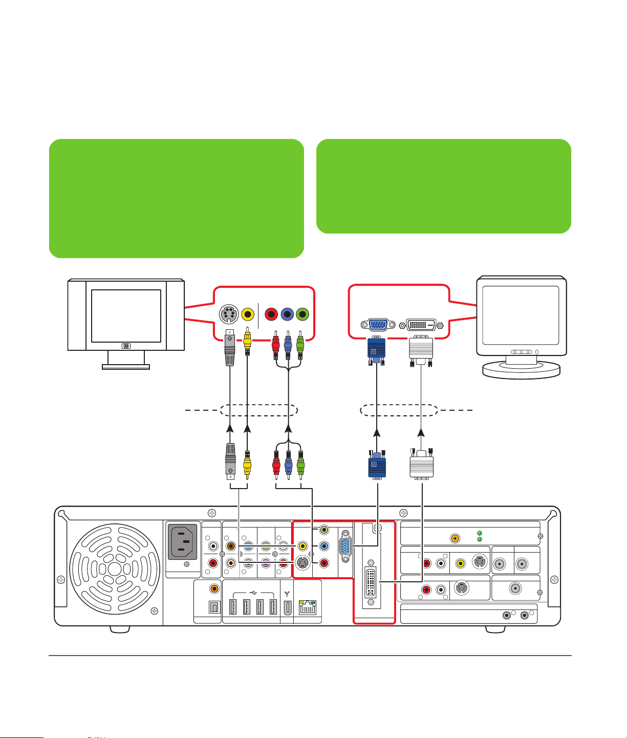
n
Component video output requires specific
configurations for certain display types and
resolutions. Go to http://www.hp.com/
support and select your model number for
instructions on using component video.
.
n
If your TV or monitor has multiple input
connections, select the correct input on the TV
or monitor.
Choose one
100-240V- 4/A 50/60Hz
S-video ComponentVideo
AUDIO IN
L
COAXIAL
OPTICAL
DIGITAL
R
AUDIO
OUT
AC IN
TV IN
AUDIO 7.1 PRE-OUT
SURROUND
SURROUND CENTER
BACK
L L L
R R
SUB
WOOFER
HI SPEED USB 2.0 ETHERNET1394
FRONT
R
VIDEO OUT
VIDEO
S-VIDEO COMPONENT
10/ 100/ 1000
Y
Pb
Pr
MONITOR IN
VGA
DVI
VGA
DIGITAL VIDEO OUT
DVI
WIRELESS LAN 802.11 b/g
REMOVABLE ANTENNA
TV SOURCE 1 IN
R
L
AUDIO
TV SOURCE 2 IN
RL
INFRARED TRANSMITTER OUT
Choose one
ACTIVITY
LINK
CABLE/ANT. IN FM ANTENNA IN
VIDEO
S-VIDEO
HDTV / SDTV ANT. IN
S-VIDEOAUDIO
DUAL
TUNER
ATSC TUNER
75
COAXIAL
12
Ω
TV (standard definition shown) and monitor out
70 HP Digital Entertainment Center
Page 77

Connecting TV Source In
This chapter describes how to connect TV source input
from a set-top box such as a cable box or satellite
receiver to the HP Digital Entertainment Center. Infrared
Transmitter cable installation is also included.
You connect the HP Digital Entertainment Center to an
existing setup for your TV signal source. This chapter
includes the most typical, and some advanced, input
options.
The HP Digital Entertainment Center supports many
different video source input options, connections, and
set-top-box configurations, such as a cable box or satellite
receiver. Your home system may have different
components.
Cable
Set-top box
Infrared Transmitter
On/Standby
HP Digital Entertainment Center
“TV Source Overview” on page 72
“Typical TV Source Connections” on page 78
“Antenna Connection” on page 80
“Cable Connection” on page 83
“Satellite Connection” on page 93
“Infrared Transmitter Connection” on page 97
For additional information on connecting the
cable box or satellite receiver, refer to the
documentation that came with your
equipment and the Start Here booklet
included.
Chapter Contents:
n
Connecting TV Source In
HP Digital Entertainment Center
Connecting TV Source In 71
Page 78

TV Source Overview
TV Signal Source Overview
You must connect a TV signal to the HP Digital
Entertainment Center for proper operation. You can
attach standard, analog NTSC TV and high-definition,
digital HDTV ATSC sources.
The back panel TV Source connectors are:
■ TV Source 1 In
■ TV Source 2 In
■ Cable/antenna In (NTSC) RF
■ HDTV/SDTV Ant. In (ATSC) RF antenna
NTSC Standard TV
An ATSC tuner that supports high-definition
TV is included with select HP Digital
Entertainment Center models only.
n
The NTSC back panel connectors are TV Source 1 In and
TV Source 2 In:
■ For an NTSC cable TV box, digital cable box, or
satellite receiver use TV Source 1 In or TV Source 2 In
(select models only).
■ For an NTSC analog cable RF coaxial connector use
Cable/antenna In. For dual-tuner systems, the
Cable/antenna In RF connector splits internally.
A set-top cable TV box is provided by your cable TV
provider to unscramble premium channels.
For Dual Tuner configurations, both TV sources must be of
the same type: either cable TV, digital cable TV, satellite
TV, or antenna. The TV sources must also have the same,
identical channel lineup; for example, if you are using
two satellite TV sources they must provide the exact same
channels. All TV viewing and scheduling is provided
through the Television Program Guide in Media Center,
so both TV sources must have identical Television Program
Guides.
The HP Digital Entertainment Center records television
and allows you to control the television channels. The
HP Digital Entertainment Center has two tuner
configurations available:
Single-tuner
TV Source
1 In
Dual-tuner
option TV
Source 2 In
A single tuner allows you to watch or
record one program only in NTSC.
You can have dual TV inputs, if your
HP Digital Entertainment Center
includes the two TV tuner option. You
can watch a show on one channel
while Media Center records another
show on a different channel. Or you
can record two different programs at
the same time, using two tuners
in NTSC.
72 HP Digital Entertainment Center
Page 79

ATSC high-definition TV
If your HP Digital Entertainment Center includes an
optional HDTV/SDTV Ant. In tuner card and dual NTSC
tuner card configuration, you can view and record ATSC
channels. Media Center supports over-the-air ATSC
digital TV.
Over-the-air ATSC digital TV requires a UHF/VHF
antenna (sold separately) to receive the digital signal.
Your location must be within an HDTV ATSC
broadcast area.
Connecting an ATSC antenna
You can attach an indoor or outdoor UHF/VHF antenna
to the HP Digital Entertainment Center to watch HDTV
ATSC through the VHF or UHF channels. A UHF/VHF
antenna receives HDTV ATSC channels, depending on
the quality (gain) of the antenna, geographic location,
and broadcast reception strength.
An internal or external roof antenna is sold separately.
You might have to reposition the antenna for best
reception. Position the antenna based on the following
general criteria:
The ATSC high-definition DTV (Digital TV) source back
panel connector is as follows:
■ HDTV/SDTV Ant. In connected to a UHF/VHF
antenna.
See the following section for more information on HDTV.
Then see the instructions to install HDTV ATSC.
Connecting TV Source In
Refer to http://www.antennaweb.org for more
information about:
■ The channels available in your area. The channels
may be color coded by zone.
■ Selecting the kind of antenna you need depending
on the channels you want to receive. Match your
antenna to your zone.
■ The direction to point your antenna.
■ Positioning an HDTV antenna for best reception.
■ Higher; the ideal position is above the roofline.
■ Closer to or facing the broadcast tower.
■ Larger for stronger signals.
■ Outdoor for less interference.
n
You can also attach an internal or external
roof VHF antenna to the HP Digital
Entertainment Center to watch NTSC
channels.
Connecting TV Source In 73
Page 80

Additional HDTV Information
What is HDTV?
HDTV (High-definition Television) is the highest quality
DTV standard. HDTV provides increased picture detail
(720p, 1080i) with a widescreen16:9 aspect ratio and
higher quality audio such as surround sound, on a
display that supports digital TV. HDTV/SDTV Ant. In is the
connector on the back of your HP Digital Entertainment
Center that you connect the ATSC signal to.
SDTV (Standard-definition Television) is the lowest quality
DTV standard.
ATSC (Advanced Television Systems Committee) is the
official name of the DTV picture format that is in use in the
United States and North America. The tuner inside your
HP Digital Entertainment Center is ATSC-capable.
DTV (Digital Television) is the umbrella term used to
describe the new digital television way of transmitting
television signals. DTV includes many formats of highdefinition TV that can broadcast an image resolution of
up to 2 million pixels.
NTSC (National Television Systems Committee) is
standard (analog) TV. Standard TV broadcasts an image
resolution of about 210,000 pixels and is distributed
today through antenna, cable, digital cable, or satellite.
About digital TV in Media Center
Digital TV for Windows
is available in the United States only. Refer to the Readme
for Update 1 for Windows XP Media Center Edition
2005 with HDTV for all digital TV requirements.
®
XP Media Center Edition 2005
Refer to the Microsoft
http://www.microsoft.com
Web site at:
74 HP Digital Entertainment Center
Page 81

TV Source Connectors Overview
Your standard television set-top box has one or more of
the following video output connectors and cables:
■ Coaxial (RF)
■ Video (composite)
■ S-video
Do not switch video types such as connecting S-video In
to TV Source 1 and Composite Video In to TV Source 2 or
a Coaxial In and a Composite Out. Not all set-top boxes
and AV receivers support signal conversion.
The type of video cable you need depends on your settop box:
Connecting a set-top box
A standard cable set-top box has only NTSC channels,
but you can connect a UHF/VHF antenna to view HDTV
ATSC channels also.
■ If your set-top box has an S-video jack, you need an
S-video cable to connect the HP Digital Entertainment
Center to your set-top box. An S-video cable
provides separate color and black-and-white image
signals, and delivers a sharper image than a
composite video cable.
■ If your set-top box has a composite video jack, you
need a composite video cable.
■ If you are connecting dual NTSC set-top box sources
to the HP Digital Entertainment Center dual NTSC
tuner with an composite video connection, use a
composite to S-video adapter (sold separately) on TV
Source 2 in.
You may need other or additional cables, depending on
your TV signal source.
If you can receive HDTV channels through cable or
satellite providers, connect the signal directly to your
TV/display. Refer to your TV/display documentation.
Connecting TV Source In
A set-top cable TV box is provided by your cable TV
provider to unscramble premium channels. You cannot
record digital TV if using the HP Digital Entertainment
Center with an HDTV cable box or HDTV satellite box.
Use an antenna to record digital TV.
Connecting TV Source In 75
Page 82

TV Source Connectors
M
(Location, availability, and number of connectors may vary.)
WIRELESS LAN 802.11 b/g
REMOVABLE ANTENNA
TV SOURCE 1 IN
L
R
AUDIO
TV SOURCE 2 IN
RL
VIDEO
INFRARED TRANSMITTER OUT
ACTIVITY
LINK
S-VIDEO
S-VIDEOAUDIO
100-240V- 4/A 50/60Hz
AC IN
AUDIO IN
COAXIAL
OPTICAL
DIGITAL
SURROUND
BACK
L
L L L
R
R R R
AUDIO
OUT
AUDIO 7.1 PRE-OUT
SURROUND CENTER
HI SPEED USB 2.0 ETHERNET1394
SUB
WOOFER
FRONT
VIDEO OUT
VIDEO
S-VIDEO COMPONENT
10/ 100/ 1000
Y
Pb
Pr
DVI
VGA
DIGITAL VIDEO OUT
Item Connector Type Color Cable
TV SOURCE 1
R
L
Audio TV Source 1 In RCA jacks White: Left
Red: Right
AUDIO
Video (composite)
RCA jack Yellow
TV Source 1 In
S-VIDEOVIDEO
S-VIDEOVIDEO
CABLE/ANT. IN F
S-video (4-pin)
TV Source 1 In
Cable/Antenna In
Y/C video
Black
Analog 4-pin
Coaxial Silver
With internal splitter to
DUAL
TUNER
dual-tuners
CABLE/ANT. IN FM ANTENNA IN
75Ω
DUAL
COAXIAL
TUNER
HDTV / SDTV ANT. IN
ATSC TUNER
12
TV SOURCE 2
Audio TV Source 2 In
(Select models only)
AUDIO
L
R
76 HP Digital Entertainment Center
RCA jacks White: Left
Red: Right
Page 83

Item Connector Type Color Cable
2 IN
S-VIDEO
HDTV / SDTV ANT. IN
S-video TV Source 2 In
(select models only)
HDTV/SDTV Ant. In Coaxial
Y/C video
Analog 4-pin
(from UHF/
Black
Silver
VHF antenna)
ATSC TUNER
UT
Infrared Transmitter Out 2 ports: 1/8
12
inch (3.5 mm)
Silver
mini-jacks
Additional cables to install the HP Digital Entertainment Center are sold separately.
Connecting TV Source In
Connecting TV Source In 77
Page 84

Typical TV Source Connections
These are only suggested configurations. Your system may be different.
Select the configuration that most closely matches your home system:
Display/video
TV source type
configuration Connector See:
Antenna Standard
NTSC from UHF/VHF antenna
HDTV
ATSC from UHF/VHF antenna
NTSC from UHF/VHF antenna
ATSC from UHF /VHF ant enna
NTSC cable and
ATSC antenna
NTSC digital
cable or satellite
and ATSC
antenna
NTSC analog cable directly
from the wall (without a set-top
box) and ATSC from UHF/
VHF antenna
One NTSC cable TV set-top
box and ATSC from UHF/VHF
antenna
Two NTSC cable TV set-top
boxes and ATSC from UHF/
VHF antenna
One NTSC digital cable or
satellite receiver and ATSC
from UHF/VHF antenna
Cable/Ant. In “Antenna (NTSC)” on
page 80
HDTV/SDTV Ant. In “Antenna (ATSC)” on
page 81
Cable/Ant. In
HDTV/SDTV Ant. In
Cable/Ant. In and
HDTV/SDTV Ant. In
TV Source 1 In and
HDTV/SDTV Ant. In
Or
Cable/Ant. In and
HDTV/SDTV Ant. in
TV Source 1 In
TV Source 2 In
HDTV/SDTV Ant. In
TV Source 1 In and
HDTV/SDTV Ant. In
Or
Cable/Ant. In and
HDTV/SDTV Ant. In
“Antenna (NTSC and
ATSC)” on page 82
“Cable (NTSC) and
Antenna (ATSC)” on
page 83
“One Cable TV Box or
Digital Cable Receiver
(NTSC) and Antenna
(ATSC)” on page 84
“Two Cable TV Boxes, or
Two Digital Cable Receivers
(NTSC) and Antenna
(ATSC)” on page 86
“One Cable TV Box or
Digital Cable Receiver
(NTSC) and Antenna
(ATSC)” on page 84
Two NTSC digital cable or
satellite receivers and ATSC
from UHF/VHF antenna
78 HP Digital Entertainment Center
TV Source 1 In
TV Source 2 In
HDTV/SDTV Ant. In
“Two Cable TV Boxes, or
Two Digital Cable Receivers
(NTSC) and Antenna
(ATSC)” on page 86
Page 85

TV source type
Display/video
configuration Connector See:
NTSC cable Cable directly from the wall
(without a cable TV set-top box
or digital cable receiver)
One cable TV set-top box or
digital cable receiver
Two cable TV set-top boxes, or
digital cable receivers
NTSC satellite One satellite receiver TV Source 1 In
Two satellite receivers TV Source 1 In
NTSC and ATSC
digital cable or
satellite
One NTSC and ATSC digital
cable or satellite receiver
Two NTSC and ATSC digital
cable or satellite receivers
Cable/Ant. In “Cable Only (NTSC)” on
TV Source 1 In
Or
Cable/Ant. In
TV Source 1 In
TV Source 2 In
Or
Cable/Ant. In
TV Source 2 In
TV Source 1 In
(to record HDTV in
standard format)
TV Source 1 In and
TV Source 2 In
(to record HDTV in
standard format)
page 88
“One Cable TV Box or
Digital Cable Receiver
(NTSC)” on page 89
“Two Cable TV Boxes, or
Two Digital Cable
Receivers” on page 91
“One Satellite Receiver
(NTSC)” on page 93
“Two Satellite Receivers
(NTSC)” on page 95
Connect the cable ATSC
signal directly to your TV/
display to view HDTV.
Refer to the TV/display
documentation.
Connect the cable ATSC
signal directly to your TV/
display to view HDTV.
Refer to the TV/display
documentation.
Connecting TV Source In
Then see:
“Infrared Transmitter Connection” on page 97 (cable TV box, digital cable receiver, or satellite receiver only)
“Connecting Video Equipment” on page 101
Connecting TV Source In 79
Page 86

Antenna Connection
(Location, availability, and number of connectors may vary.)
Antenna (NTSC)
:
If you are using a NTSC UHF/VHF broadcast television
antenna (sold separately) with no cable TV box, digital
cable box, or satellite receiver, do the following to
connect the TV signal source:
1 Plug the connector of a coaxial cable from
your external or internal TV antenna into
the Cable/Ant. In connector on the back of
the HP Digital Entertainment Center.
2 Turn the connector to tighten it.
CABLE/ANT. IN
TUNER
DUAL
Roof TV Antenna
VHF
Antenna
UHF
Antenna
Coaxial
AUDIO IN
L
100-240V- 4/A 50/60Hz
AC IN
R
COAXIAL
OPTICAL
DIGITAL
TV signal source — TV antenna
80 HP Digital Entertainment Center
AUDIO 7.1 PRE-OUT
SURROUND
SURROUND CENTER
BACK
L L L
R R
AUDIO
HI SPEED USB 2.0 ETHERNET1394
OUT
SUB
WOOFER
FRONT
R
VIDEO OUT
VIDEO
S-VIDEO COMPONENT
10/ 100/ 1000
Y
Pb
Pr
VGA
DIGITAL VIDEO OUT
WIRELESS LAN 802.11 b/g
REMOVABLE ANTENNA
DVI
TV SOURCE 1 IN
R
L
AUDIO
TV SOURCE 2 IN
RL
INFRARED TRANSMITTER OUT
VIDEO
S-VIDEO
S-VIDEOAUDIO
ACTIVITY
LINK
CABLE/ANT. IN FM ANTENNA IN
DUAL
TUNER
HDTV / SDTV ANT. IN
ATSC TUNER
75
Ω
COAXIAL
12
Page 87

Antenna (ATSC)
:
To connect an HDTV signal source to your HP Digital
Entertainment Center, do the following:
Roof TV Antenna
1 Connect a coaxial cable from your
UHF/VHF antenna into the HDTV/SDTV
Ant. In connector on the back of the HP
Digital Entertainment Center.
2 Turn the connector to tighten it.
AUDIO IN
L
100-240V- 4/A 50/60Hz
AC IN
COAXIAL
OPTICAL
DIGITAL
R
AUDIO
OUT
HDTV / SDTV ANT. IN
AUDIO 7.1 PRE-OUT
SURROUND
SURROUND CENTER
BACK
L L L
R R R
SUB
WOOFER
HI SPEED USB 2.0 ETHERNET1394
ATSC TUNER
FRONT
VIDEO OUT
VIDEO
S-VIDEO COMPONENT
10/ 100/ 1000
Y
Pb
Pr
VGA
DIGITAL VIDEO OUT
VHF
Antenna
UHF
Antenna
Connecting TV Source In
Coaxial
WIRELESS LAN 802.11 b/g
REMOVABLE ANTENNA
DVI
TV SOURCE 1 IN
L
R
AUDIO
TV SOURCE 2 IN
RL
INFRARED TRANSMITTER OUT
VIDEO
S-VIDEO
S-VIDEOAUDIO
ACTIVITY
LINK
CABLE/ANT. IN FM ANTENNA IN
DUAL
TUNER
HDTV / SDTV ANT. IN
ATSC TUNER
75Ω
COAXIAL
12
TV signal source — HDTV antenna
Connecting TV Source In 81
Page 88

Antenna (NTSC and ATSC)
If you are using a VHF and UHF broadcast television
antenna (sold separately) with no cable TV box, digital
cable box, or satellite receiver, do the following to
connect the NTSC and ATSC TV signal source to your
HP Digital Entertainment Center:
Roof Antenna
VHF
Antenna
1 Install a splitter (provided) as shown in the following
illustration (select models only). Connect the splitter
input to the antenna (outdoor shown).
2 Connect two coaxial cables to the splitter outputs.
Turn the connectors to tighten them.
3 Connect a coaxial cable into the Cable/Ant.
In connector on the back of the HP Digital
Entertainment Center. Turn the connector to
tighten it.
4 Connect a coaxial cable into the
HDTV/SDTV Ant. In connector on the
back of the HP Digital Entertainment
Center. Turn the connector to tighten it.
100-240V- 4/A 50/60Hz
AC IN
AUDIO IN
COAXIAL
OPTICAL
DIGITAL
SURROUND
BACK
L
L L L
R
R R R
AUDIO
OUT
AUDIO 7.1 PRE-OUT
SURROUND CENTER
HI SPEED USB 2.0 ETHERNET1394
CABLE/ANT. IN
HDTV / SDTV ANT. IN
ATSC TUNER
FRONT
SUB
WOOFER
DUAL
TUNER
VIDEO
S-VIDEO COMPONENT
10/ 100/ 1000
VIDEO OUT
Y
Pb
Pr
VGA
DIGITAL VIDEO OUT
UHF
Antenna
Coaxial
Splitter
WIRELESS LAN 802.11 b/g
REMOVABLE ANTENNA
DVI
TV SOURCE 1 IN
L
R
VIDEOAUDIO S-VIDEO
TV SOURCE 2 IN
RL
INFRARED TRANSMITTER OUT
S-VIDEOAUDIO
2 Way Splitter
ACTIVITY
LINK
CABLE/ANT. IN FM ANTENNA IN
1
DTV
12
HDTV and standard signal source — TV antenna
82 HP Digital Entertainment Center
Page 89

Cable Connection
(Location, availability, and number of connectors may vary.)
Cable (NTSC) and Antenna (ATSC)
.
To connect standard cable without a set-top box and a
HDTV/SDTV Ant. In input to your HP Digital Entertainment
Center, do the following to connect the NTSC and ATSC
TV signal sources:
1 Plug the connector of a coaxial cable from
your TV cable (wall) into the Cable/Ant. In
connector on the back of the HP Digital
Entertainment Center.
CABLE/ANT. IN
TUNER
DUAL
Antenna
VHF
Antenna
Roof Antenna
UHF
Connecting TV Source In
2 Turn the connector to tighten it.
3 Connect the coaxial cable from the
UHF/VHF antenna into the HDTV/SDTV
Ant. In connector on the back of the HP
Digital Entertainment Center.
HDTV / SDTV ANT. IN
ATSC TUNER
4 Turn the connector to tighten it.
AUDIO IN
AUDIO 7.1 PRE-OUT
SURROUND
SURROUND CENTER
BACK
L
L L L
100-240V- 4/A 50/60Hz
AC IN
R
COAXIAL
OPTICAL
DIGITAL
R R R
AUDIO
HI SPEED USB 2.0 ETHERNET1394
OUT
SUB
WOOFER
TV signal source NTSC cable and ATSC UHF/VHF antenna
FRONT
VIDEO OUT
VIDEO
S-VIDEO COMPONENT
10/ 100/ 1000
Y
Pb
Pr
DVI
VGA
DIGITAL VIDEO OUT
Cable From Wall
Coaxial
WIRELESS LAN 802.11 b/g
REMOVABLE ANTENNA
TV SOURCE 1 IN
R
L
AUDIO
TV SOURCE 2 IN
RL
INFRARED TRANSMITTER OUT
VIDEO
S-VIDEO
S-VIDEOAUDIO
ACTIVITY
LINK
CABLE/ANT. IN FM ANTENNA IN
HDTV / SDTV ANT. IN
DUAL
TUNER
ATSC TUNER
75
COAXIAL
Coaxial
Ω
12
Connecting TV Source In 83
Page 90

One Cable TV Box or Digital Cable Receiver (NTSC) and Antenna (ATSC)
To connect a standard set-top box (sold separately) and
an HDTV/SDTV Ant. In input to your HP Digital
Entertainment Center using a standard set-top box,
satellite receiver, or digital cable receiver with S-video or
composite video output, do the following:
1 Make sure that a coaxial cable connector from your
cable TV source (wall) is plugged into the set-top box
or digital cable receiver In connector.
2 Connect a video cable:
a Choose a video out connector:
■ Coaxial (RF)
■ Video (composite)
■ S-video
b Connect the video cable from the set-top
box or digital cable receiver back panel Video
Output connector.
c Connect the video cable into the HP Digital
Entertainment Center back panel TV Source 1 In
connector.
3 Connect stereo audio cables (skip this step if using
coaxial [RF]):
a From the set-top box or digital cable receiver
back panel Audio Out right (red) and Audio Out
left (white) connectors.
b Into the HP Digital Entertainment Center back
panel TV Source 1 In Audio right (red) and Audio
left (white) connectors.
4 Connect the coaxial cable from the UHF/VHF
antenna into the HDTV/SDTV Ant. In HDTV/SDTV
Ant. In connector on the back of the HP Digital
Entertainment Center.
5 Connect the set-top box Infrared Transmitter cable
(required for signal). See “Infrared Transmitter
Connection” on page 97.
84 HP Digital Entertainment Center
Page 91

.
Roof TV Antenna
Cable
Wall
Coaxial
VHF
Antenna
UHF
Antenna
OUT
Choose one
Video Coaxial
S-video
AUDIO IN
AUDIO 7.1 PRE-OUT
SURROUND
SURROUND CENTER
BACK
L
L L L
100-240V- 4/A 50/60Hz
AC IN
COAXIAL
OPTICAL
DIGITAL
R
R R
AUDIO
OUT
SUB
WOOFER
HI SPEED USB 2.0 ETHERNET1394
TV Source 1
VIDEO OUT
FRONT
R
10/ 100/ 1000
VIDEO
S-VIDEO COMPONENT
Y
Pb
Pr
VGA
Set-top box 1
DVI
DIGITAL VIDEO OUT
Infrared Transmitter
WIRELESS LAN 802.11 b/g
REMOVABLE ANTENNA
TV SOURCE 1 IN
R
L
AUDIO
VIDEO
TV SOURCE 2 IN
RL
S-VIDEO
S-VIDEOAUDIO
INFRARED TRANSMITTER OUT
ACTIVITY
LINK
CABLE/ANT. IN FM ANTENNA IN
DUAL
TUNER
HDTV / SDTV ANT. IN
ATSC TUNER
75
COAXIAL
Connecting TV Source In
Coaxial
Ω
12
TV signal source — one cable TV or digital cable box (NTSC) and ATSC UHF/VHF antenna
Connecting TV Source In 85
Page 92

Two Cable TV Boxes, or Two Digital Cable Receivers (NTSC) and Antenna (ATSC)
You must have two identical set-top boxes — such as two
digital cable receivers, two satellite receivers, or two
cable TV boxes (sold separately) — from the same TV
source and the HP Digital Entertainment Center dual-tuner
option (select models only) to set this up. This
configuration will allow you to watch live TV on one
channel and record another channel at the same time.
Connect the NTSC TV signal source from each set-top box
or digital cable receiver into each of the HP Digital
Entertainment Center tuners’ TV Source 1 and TV
Source 2.
If you are using two matching set-top cable boxes, with
S-video or composite video output, do the following to
connect two tuners and a HDTV ATSC input to your
HP Digital Entertainment Center:
1 Make sure that:
■ Cable TV box: A coaxial cable connector
from your cable source (wall) is plugged into
a cable splitter (provided), then into each cable
set-top box In connector. This setup is similar to
the illustration “TV signal source — two digital
cable boxes (NTSC)” on page 92.
■ Digital cable receiver: A coaxial cable
connector from two cable sources (wall) is
plugged into each digital cable receiver IN
connector. See “TV signal source — two digital
cable boxes (NTSC)” on page 92.
c Connect the video cable into the HP Digital
Entertainment Center back panel TV Source 1 In
connector.
3 Connect stereo audio cables for set-top box 1
(skip this step if using coaxial [RF]):
a From the set-top box or digital cable receiver
back Audio Out right (red) and Audio Out left
(white) connectors.
b Into the HP Digital Entertainment Center back
panel TV Source 1 In Audio right (red) and Audio
left (white) connectors.
4 Connect a video cable for set-top box 2:
a Choose a video out connector; use the same type
as set-top box 1:
■ Video (composite)
■ S-video
b Connect the video cable from the
set-top box or digital cable receiver back
panel video output connector.
c Connect the video cable into the HP Digital
Entertainment Center back panel TV Source 2 In
connector.
5 Connect stereo audio cables for set-top box 2
(skip this step if using coaxial [RF]):
2 Connect a video cable for set-top box 1.
a Choose a Video Out connector:
■ Video (composite)
■ S-video
b Connect the video cable from the
set-top box or digital cable receiver back
panel video output connector.
86 HP Digital Entertainment Center
a From the set-top box or digital cable receiver
back Audio Out right (red) and Audio Out left
(white) connectors.
b Into the HP Digital Entertainment Center back
panel TV Source 2 In Audio right (red) and Audio
left (white) connectors.
6 Connect the coaxial cable from the UHF/VHF
antenna into the HDTV/SDTV Ant. In connector on
the back of the HP Digital Entertainment Center.
Page 93
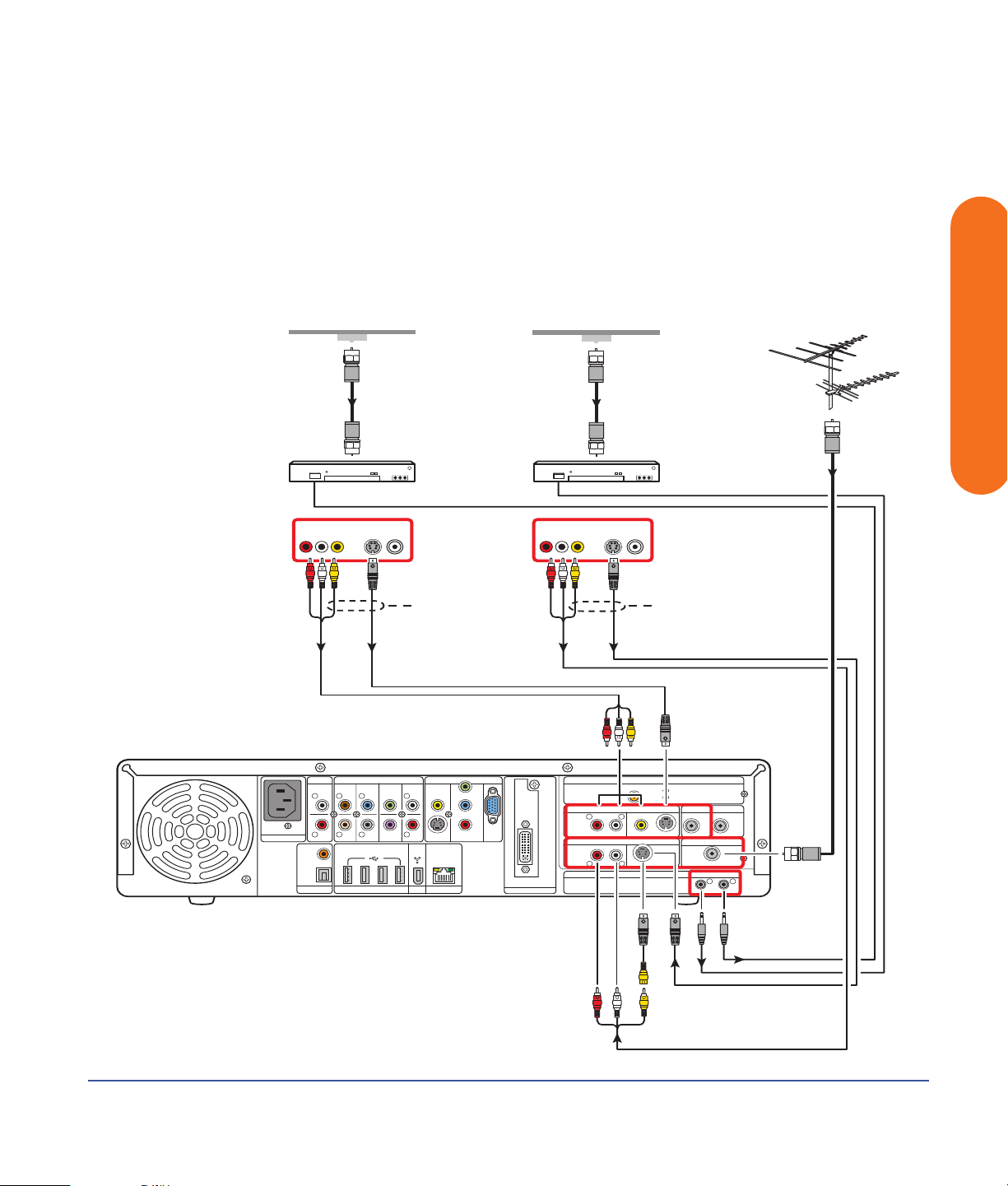
7 Connect the set-top box 1 Infrared Transmitter cable
(required for signal). See “Infrared Transmitter
Connection” on page 97.
.
Wall
Cable
Coaxial
Source 1
Set-top box 1
Source 2
Set-top box 2
8 Connect the set-top box 2 Infrared Transmitter cable
(required for signal). See “Infrared Transmitter
Connection” on page 97.
Wall
Cable
Antenna
Coaxial
Infrared Transmitter
Roof TV
Antenna
VHF
UHF
Antenna
Coaxial
Connecting TV Source In
Video
100-240V- 4/A 50/60Hz
AC IN
AUDIO IN
COAXIAL
OPTICAL
DIGITAL
SURROUND
BACK
L
L L L
R
R R
AUDIO
OUT
S-video
AUDIO 7.1 PRE-OUT
SURROUND CENTER
HI SPEED USB 2.0 ETHERNET1394
WOOFER
FRONT
R
SUB
VIDEO OUT
VIDEO
S-VIDEO COMPONENT
10/ 100/ 1000
Video S-video
Y
Pb
DVI
Pr
VGA
DIGITAL VIDEO OUT
VIDEO OUTVIDEO OUT
WIRELESS LAN 802.11 b/g
REMOVABLE ANTENNA
TV SOURCE 1 IN
L
R
AUDIO
TV SOURCE 2 IN
RL
INFRARED TRANSMITTER OUT
Note: Connect same
set-top box only
Choose oneChoose one
ACTIVITY
LINK
CABLE/ANT. IN FM ANTENNA IN
S-VIDEO
DUAL
TUNER
HDTV / SDTV ANT. IN
ATSC TUNER
VIDEO
S-VIDEOAUDIO
75
COAXIAL
Ω
12
TV signal source — two cable boxes (NTSC) and ATSC UHF/VHF antenna
Connecting TV Source In 87
Page 94

Cable Only (NTSC)
If you are using a standard cable without a set-top box or
digital cable receiver, do the following to connect the
NTSC-only TV signal source:
1 Plug the connector of a coaxial cable from
your TV cable (wall) into the Cable/Ant
connector on the back of the HP Digital
Entertainment Center. This connection
supplies the TV signal source for both TV tuners.
100-240V- 4/A 50/60Hz
AC IN
AUDIO IN
COAXIAL
OPTICAL
DIGITAL
SURROUND
BACK
L
L L L
R
R R
AUDIO
OUT
AUDIO 7.1 PRE-OUT
SURROUND CENTER
HI SPEED USB 2.0 ETHERNET1394
SUB
WOOFER
CABLE/ANT. IN
TUNER
FRONT
R
DUAL
VIDEO OUT
VIDEO
S-VIDEO COMPONENT
10/ 100/ 1000
2 Turn the connector to tighten it.
.
Cable
Wall
WIRELESS LAN 802.11 b/g
Y
Pb
Pr
DVI
VGA
DIGITAL VIDEO OUT
REMOVABLE ANTENNA
TV SOURCE 1 IN
R
AUDIO
TV SOURCE 2 IN
RL
INFRARED TRANSMITTER OUT
Coaxial
L
VIDEO
S-VIDEO
S-VIDEOAUDIO
ACTIVITY
LINK
CABLE/ANT. IN FM ANTENNA IN
DUAL
TUNER
HDTV / SDTV ANT. IN
ATSC TUNER
75
COAXIAL
12
Ω
TV signal source (NTSC cable)
88 HP Digital Entertainment Center
Page 95

One Cable TV Box or Digital Cable Receiver (NTSC)
Connect the NTSC TV signal source from the standard
cable TV set-top box or digital cable receiver (sold
separately) into the HP Digital Entertainment Center.
If you are using a standard set-top box or digital cable
receiver with S-video or composite video output, do the
following:
1 Make sure that a coaxial cable connector from your
cable TV source (wall) is plugged into the set-top box
or digital cable receiver In connector.
2 Connect a video cable:
a Choose a video out connector:
■ Coaxial (RF)
■ Video (composite)
■ S-video
b Connect the video cable from the set-top
box or digital cable receiver back panel Video
Output connector.
c Connect the video cable into the HP Digital
Entertainment Center back panel TV Source 1 In
connector.
3 Connect stereo audio cables (skip this step if using
coaxial [RF]):
a From the set-top box or digital cable receiver
back panel Audio Out right (red) and Audio Out
left (white) connectors.
b Into the HP Digital Entertainment Center back
panel TV Source 1 In Audio right (red) and Audio
left (white) connectors.
4 Connect the set-top box Infrared Transmitter cable
(required for signal). See “Infrared Transmitter
Connection” on page 97.
Connecting TV Source In
Connecting TV Source In 89
Page 96

.
Cable
From
Wall
Coaxial
OUT
Choose one
Video Coaxial
S-video
100-240V- 4/A 50/60Hz
AC IN
AUDIO IN
COAXIAL
OPTICAL
DIGITAL
SURROUND
BACK
L
L L L
R
R R R
AUDIO
OUT
AUDIO 7.1 PRE-OUT
SURROUND CENTER
SUB
WOOFER
HI SPEED USB 2.0 ETHERNET1394
TV Source 1
VIDEO OUT
FRONT
VIDEO
S-VIDEO COMPONENT
10/ 100/ 1000
Y
Pb
Pr
VGA
DIGITAL VIDEO OUT
Set-top box 1
Infrared Transmitter
DVI
WIRELESS LAN 802.11 b/g
REMOVABLE ANTENNA
TV SOURCE 1 IN
L
R
AUDIO
TV SOURCE 2 IN
RL
VIDEO
INFRARED TRANSMITTER OUT
S-VIDEO
S-VIDEOAUDIO
ACTIVITY
LINK
CABLE/ANT. IN FM ANTENNA IN
DUAL
TUNER
HDTV / SDTV ANT. IN
ATSC TUNER
75Ω
COAXIAL
12
TV signal source — one cable TV or digital cable box (NTSC)
90 HP Digital Entertainment Center
Page 97

Two Cable TV Boxes, or Two Digital Cable Receivers
You must have two identical set-top boxes, such as two
digital cable receivers or two cable TV boxes (sold
separately), from the same TV source and the HP Digital
Entertainment Center dual-tuner option (select models
only) to set this up. This configuration will allow you to
watch live TV on one channel and record another channel
at the same time.
Connect the TV signal source from each set-top box or
digital cable receiver into each of the HP Digital
Entertainment Center tuners’ TV Source 1 and TV
Source 2.
If you are using two matching set-top cable boxes or
digital cable receivers with S-video or composite video
output, do the following:
1 Make sure that:
■ Cable TV box: A coaxial cable connector
from your cable source (wall) is plugged into
a cable splitter (provided), then into each cable
set-top box In connector. This setup is similar to
the illustration “TV signal source — two digital
cable boxes (NTSC)” on page 92.
■ Digital cable receiver: A coaxial cable
connector from two cable sources (wall) is
plugged into each digital cable receiver IN
connector. See “TV signal source — two digital
cable boxes (NTSC)” on page 92.
2 Connect a video cable for set-top box 1.
a Choose a Video Out connector:
■ Video (composite)
■ S-video
b Connect the video cable from the
set-top box or digital cable receiver back
panel video output connector.
c Connect the video cable into the HP Digital
Entertainment Center back panel TV Source 1 In
connector.
3 Connect stereo audio cables for set-top box 1 (skip
this step if using coaxial [RF]):
a From the set-top box or digital cable receiver
back Audio Out right (red) and Audio Out left
(white) connectors.
b Into the HP Digital Entertainment Center back
panel TV Source 1 In Audio right (red) and Audio
left (white) connectors.
4 Connect a video cable for set-top box 2:
a Choose a video out connector; use the same type
as set-top box 1:
■ Video (composite)
■ S-video
b Connect the video cable from the
set-top box or digital cable receiver back
panel video output connector.
c Connect the video cable into the HP Digital
Entertainment Center back panel TV Source 2 In
connector.
5 Connect stereo audio cables for set-top box 2 (skip
this step if using coaxial [RF]):
a From the set-top box or digital cable receiver
back Audio Out right (red) and Audio Out left
(white) connectors.
b Into the HP Digital Entertainment Center back
panel TV Source 2 In Audio right (red) and Audio
left (white) connectors.
Connecting TV Source In
Connecting TV Source In 91
Page 98

6 Connect the set-top box 1 Infrared Transmitter cable
(required for signal). See “Infrared Transmitter
Connection” on page 97.
.
Cable From Wall Cable From Wall
7 Connect the set-top box 2 Infrared Transmitter cable
(required for signal). See “Infrared Transmitter
Connection” on page 97.
Source 1
Set-top box 1
100-240V- 4/A 50/60Hz
Video
AC IN
AUDIO IN
L
R
COAXIAL
OPTICAL
DIGITAL
AUDIO 7.1 PRE-OUT
SURROUND
BACK
L L L
R R
AUDIO
HI SPEED USB 2.0 ETHERNET1394
OUT
Coaxial
S-video
SURROUND CENTER
WOOFER
FRONT
R
SUB
Source 2
Set-top box 2
VIDEO OUT
Y
VIDEO
Pb
Pr
S-VIDEO COMPONENT
10/ 100/ 1000
VGA
Coaxial
VIDEO OUTVIDEO OUT
Video S-video
WIRELESS LAN 802.11 b/g
REMOVABLE ANTENNA
DVI
DIGITAL VIDEO OUT
TV SOURCE 1 IN
R
L
AUDIO
TV SOURCE 2 IN
RL
INFRARED TRANSMITTER OUT
Infrared Transmitter
Note: Connect same
set-top box only
Choose oneChoose one
ACTIVITY
LINK
CABLE/ANT. IN FM ANTENNA IN
75
DUAL
VIDEO
S-VIDEO
S-VIDEOAUDIO
TUNER
HDTV / SDTV ANT. IN
ATSC TUNER
COAXIAL
12
Ω
TV signal source — two digital cable boxes (NTSC)
92 HP Digital Entertainment Center
Page 99

Satellite Connection
(Location, availability, and number of connectors may vary.)
One Satellite Receiver (NTSC)
Connect the TV signal source from the satellite receiver
into the HP Digital Entertainment Center.
If you are using a satellite receiver (sold separately) with
S-video or composite video output, do the following:
1 Make sure that a coaxial cable connector from your
dish source is plugged into the satellite receiver In
connector.
2 Connect a video cable.
a Choose a Video Out connector:
■ Coaxial (RF)
■ Video (composite)
■ S-video
b Connect the video cable from the
satellite receiver back panel video output
connector.
c Connect the video cable into the HP Digital
Entertainment Center back panel TV Source 1 In
connector.
3 Connect stereo audio cables (skip this step if using
coaxial [RF]):
Connecting TV Source In
a From the satellite receiver back panel Audio Out
right (red) connector and Audio Out left (white)
connectors.
b Into the HP Digital Entertainment Center back
panel TV Source 1 In Audio right (red) and Audio
left (white) connectors.
4 Connect the satellite receiver Infrared Transmitter
cable (required for signal). See “Infrared Transmitter
Connection” on page 97.
Connecting TV Source In 93
Page 100
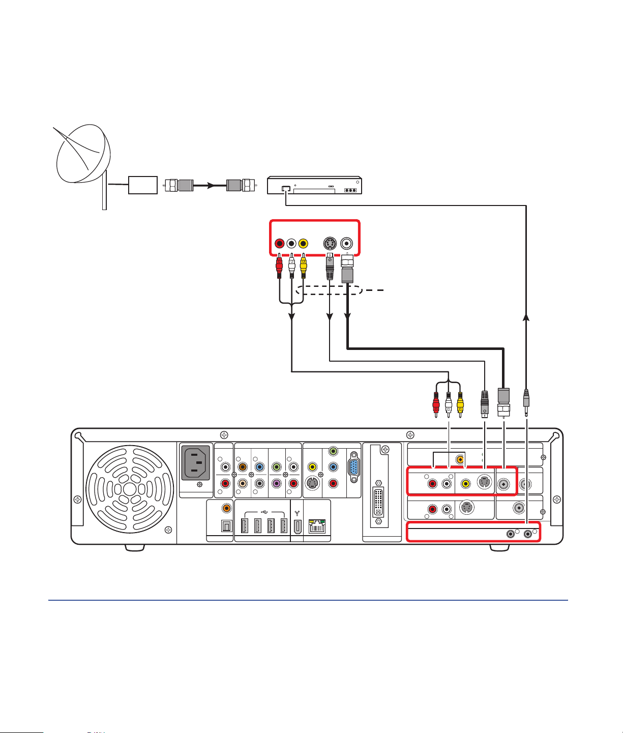
.
Coaxial
100-240V- 4/A 50/60Hz
AC IN
AUDIO IN
L
R
COAXIAL
OPTICAL
DIGITAL
AUDIO 7.1 PRE-OUT
SURROUND
SURROUND CENTER
BACK
L L L
R R R
AUDIO
HI SPEED USB 2.0 ETHERNET1394
OUT
Satellite Receiver
OUT
Video
VIDEO OUT
FRONT
VIDEO
SUB
WOOFER
S-VIDEO COMPONENT
10/ 100/ 1000
Y
Pb
Pr
CoaxialS-video
VGA
DIGITAL VIDEO OUT
Choose one
TV Source 1
DVI
R
RL
Infrared Transmitter
WIRELESS LAN 802.11 b/g
REMOVABLE ANTENNA
TV SOURCE 1 IN
L
AUDIO
TV SOURCE 2 IN
INFRARED TRANSMITTER OUT
VIDEO
S-VIDEO
S-VIDEOAUDIO
ACTIVITY
LINK
CABLE/ANT. IN FM ANTENNA IN
HDTV / SDTV ANT. IN
DUAL
TUNER
ATSC TUNER
75Ω
COAXIAL
12
TV signal source — one satellite receiver (NTSC)
94 HP Digital Entertainment Center
 Loading...