

Page 1

English
upgrading and
servicing the pc
Page 2

The information in this document is subject to change without
notice.
Hewlett-Packard
®
Company makes no warranty of any kind with
regard to this material, including, but not limited to, the implied
warranties of merchantability and fitness for a particular purpose.
HP shall not be liable for errors contained herein or for incidental
or consequential damages in connection with the furnishing,
performance, or use of this material.
HP assumes no responsibility for the use or reliability of its software
on equipment that is not furnished by HP.
This document contains proprietary information that is protected by
copyright. All rights are reserved. No part of this document may be
photocopied, reproduced, or translated to another language
without the prior written consent of HP.
Hewlett-Packard Company
Home Products Division
P.O. Box 4010
Cupertino, CA 95015-4010
USA
© Hewlett-Packard Company, 2001. All rights reserved.
Hewlett-Packard is a registered trademark of Hewlett-Packard
Company in the United States of America and other countries.
Other brand or product names are trademarks of their respective
holders.
Page 3

English
Features of the HP Pavilion home PC .... 1
Opening the Computer .........................2
Before You Begin .............................................. 3
Removing the Side Panel ................................... 4
Removing the Fan Duct...................................... 5
Removing the Drive Cage .................................. 6
Adding Memory................................... 7
DIMMs ............................................................ 8
DDR DIMMs ..................................................... 8
RIMMs............................................................. 8
Installing a Memory Module .............................. 9
Removing a Memory Module ........................... 11
Installing Add-In Cards....................... 12
What Is Plug and Play? ................................... 14
If the New Card or Device Isn’t Working ........... 14
Adding and Removing Drives............. 15
Installing a Second Hard Drive......................... 15
Removing the Preinstalled Hard Drive ............... 16
Replacing the Diskette Drive............................. 17
Replacing the Optical Drive ............................. 18
Replacing the Battery......................... 20
Closing the Computer......................... 21
Replacing the Drive Cage................................ 21
Replacing the Fan Duct ................................... 23
Replacing the Side Panel................................. 23
Regulatory and Safety Information .... 25
ENERGY STAR Compliance ............................. 28
Operating Specifications ................................. 41
Index ................................................ 42
Contents
Page 4

Page 5

English
Features of the
HP Pavilion home PC
On the top of the chassis is a CD holder (A).
Store the CDs that came with the HP Pavilion
inside this compartment, so you can quickly
locate them if you ever need to reinstall any
of the system applications.
To connect components to the front of the PC, flip
up the port cover (B) and plug the cables into the
corresponding connectors.
B
A
Note:
The power supply is pre-set for the country in which
you purchased the HP Pavilion. If you move to
another location, please make sure you check the
voltage requirements in the country you reside
before turning on the PC.
Page 6
Opening the Computer
Warning:
The HP Pavilion is heavy; be
sure to use ergonomically correct lifting
procedures when moving the computer.
Avertissement :
L’ord inat eur
HP Pavilion est lourd ; suivez des
procédures ergonomiques lorsque vous l
e
déplacez.
Warning:
Electrostatic discharge (ESD)
can damage disk drives, add-in cards,
and other components. If an ESD station
is not available, wear a wrist strap
attached to a metal part of the computer.
Place cards on a conductive foam pad or
inside the conductive wrapper they came
in; do not place the cards on top of the
wrapper.
Avertissement :
Des décharges
électrostatiques peuvent endommager les
unités de disque, cartes d’extension et
autres composants. Si vous ne disposez
pas d’une station de protection contre les
décharges électrostatiques, portez un
bracelet antistatique relié à une partie
métallique de l’ordinateur. Placez les
cartes sur un tapis en mousse conducteur
ou dans leur emballage, mais ne les
posez jamais sur leur emballage.
Warning:
Do not operate the system
with the cover removed. Always replace
the cover before turning on the system.
Avertissement :
N’utilisez pas le
système lorsque son capot est ouvert.
Remettez toujours le capot en place
avant de mettre le système sous tension.
Page 7

English
Before You Begin
Read the following items before attempting to
upgrade or service the computer:
3
These procedures assume familiarity with the
general terminology associated with personal
computers and with the safety practices and
regulatory compliance required for using and
modifying electronic equipment.
3
Set up an equipment log to record the system
model and serial numbers, all installed
options, and other information about the
system. If you need this information, it will be
easier to consult the log than to open up and
examine the system.
3
HP recommends that you use an antistatic wrist
strap and a conductive foam pad when
working on the system.
3
Disconnect the system from any
telecommunications links, networks,
or modems, and then disconnect the system
power source before performing any of the
procedures described in this guide. Failure to
do so before you open the system or do any
procedures can result in personal injury or
equipment damage.
Note:
Disconnect the modem/phone cable before
disconnecting the power cord from the system.
To gain access to the inside of the computer,
remove the side panel.
Warning:
Please read the
“Additional
Safety Information”
located at the end of
this document before installing and
connecting your system to the electrical
power system.
Avertissement :
Prière de lire les
consignes additionnelles de sécurité
à la
fin de ce document avant d’installer et
d’alimenter votre système informatique.
Page 8
Removing the Side Panel
You must remove the side panel to add memory,
insert add-in cards, install or remove drives, or
change the battery.
1
Turn off the computer and all peripherals.
2
Disconnect the modem/phone cable.
3
Disconnect the power cord and all other
attached cables (such as the keyboard, mouse,
and monitor).
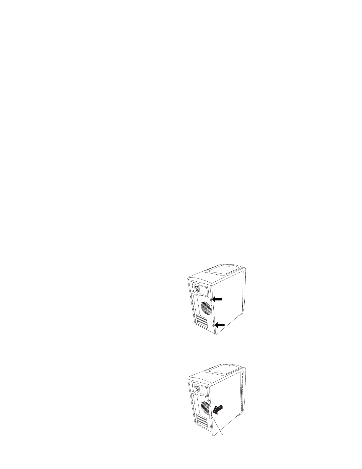
4
Loosen the two thumbscrews on the right side
of the back panel. The first time you loosen
these screws you’ll need a flathead
screwdriver. (These screws do not detach;
they’ll stay on the side panel loosely until you
tighten them again.)
5
Stand behind the computer, and place one
hand on top of the chassis.
6
Grasp the handle (A) with your other hand
and pull the panel towards you until it stops.
A
7
Lift the panel up and out. Set the panel aside.
Page 9
English
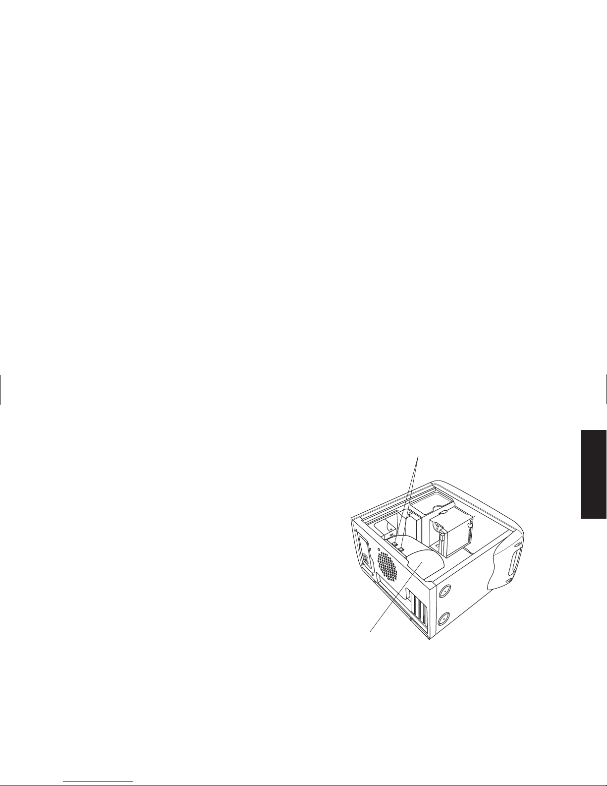
Removing the Fan Duct
To access some components on the motherboard,
you may need to remove the fan duct.
Note:
Make sure the computer is turned off and the
modem/phone cable and power cord are
disconnected from the computer.
1
Remove the side panel (see “Removing the
Side Panel” on page 4).
2
Gently lay the computer on its side.
3
To disengage the fan duct (B), push down on
the two tabs (C). You can push with your
fingers or a pen.
C
B
4
Rotate the fan duct down and out to remove it
from the chassis.
Page 10
Removing the Drive Cage
The HP Pavilion has two drive cages. The top
cage that holds the CD drive(s) is stationary. The
bottom cage holds the diskette and hard drive
and is removable. You may need to remove this
bottom drive cage to access internal components
or to add or replace a hard drive.
Note:
Make sure the computer is turned off and the
modem/phone cable and power cord are
disconnected from the computer.
1
Remove the side panel (see “Removing the
Side Panel” on page 4).
2
Gently lay the computer on its side.
3
Remove the fan duct (see “Removing the Fan
Duct” on page 5).
4
Remove the power and IDE cables from the
back of the diskette and hard drives. Make
note of each connection before disconnecting
the cables.
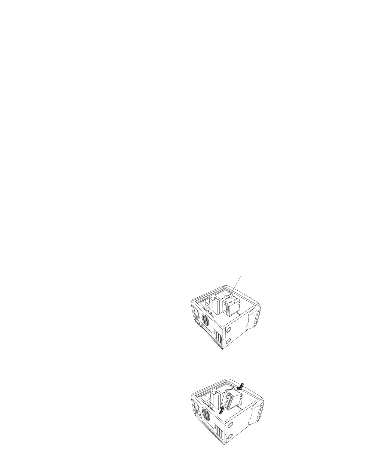
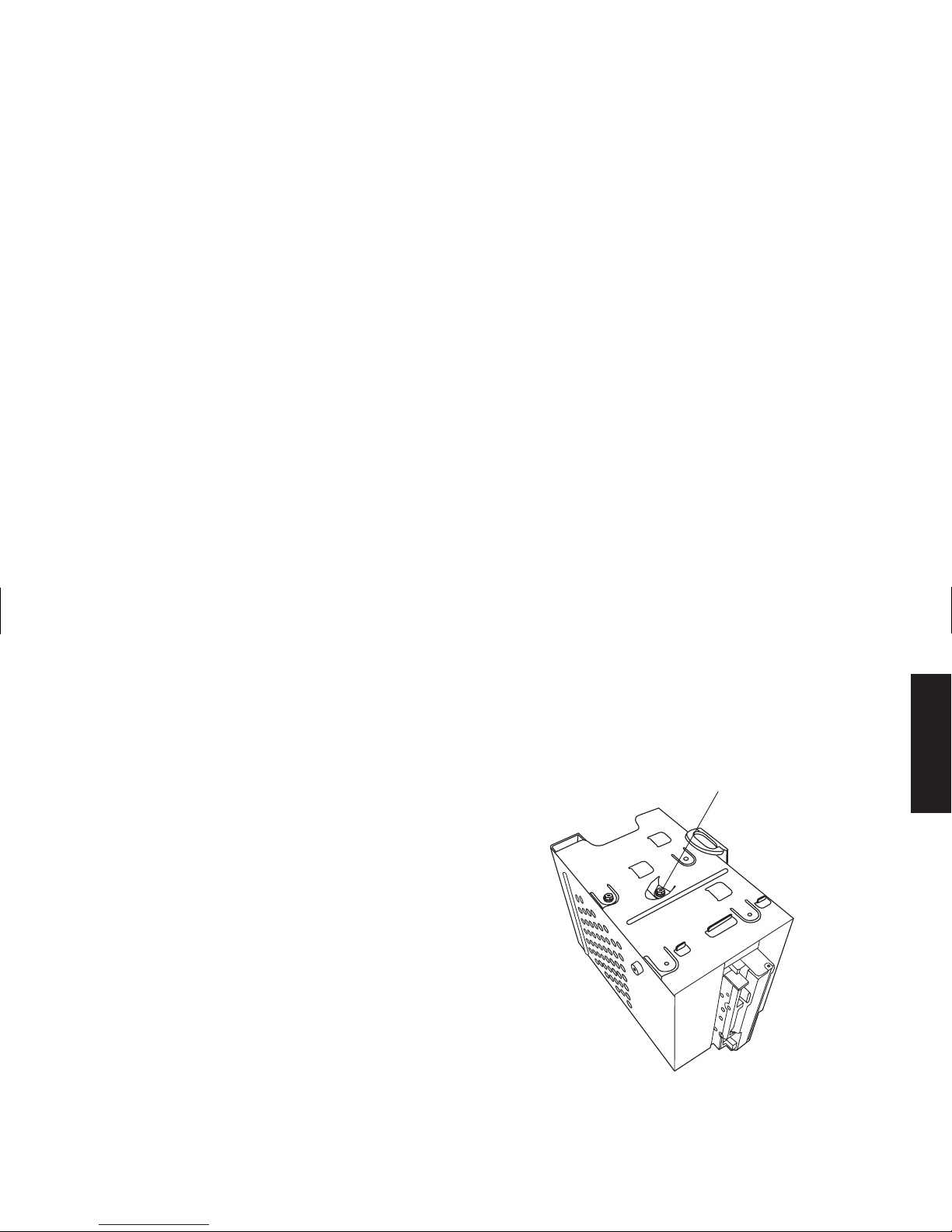
5
Push down on the drive cage release tab (D).
D
6
Hold the release tab down as you rotate the
cage up and lift it out.
Page 11
English
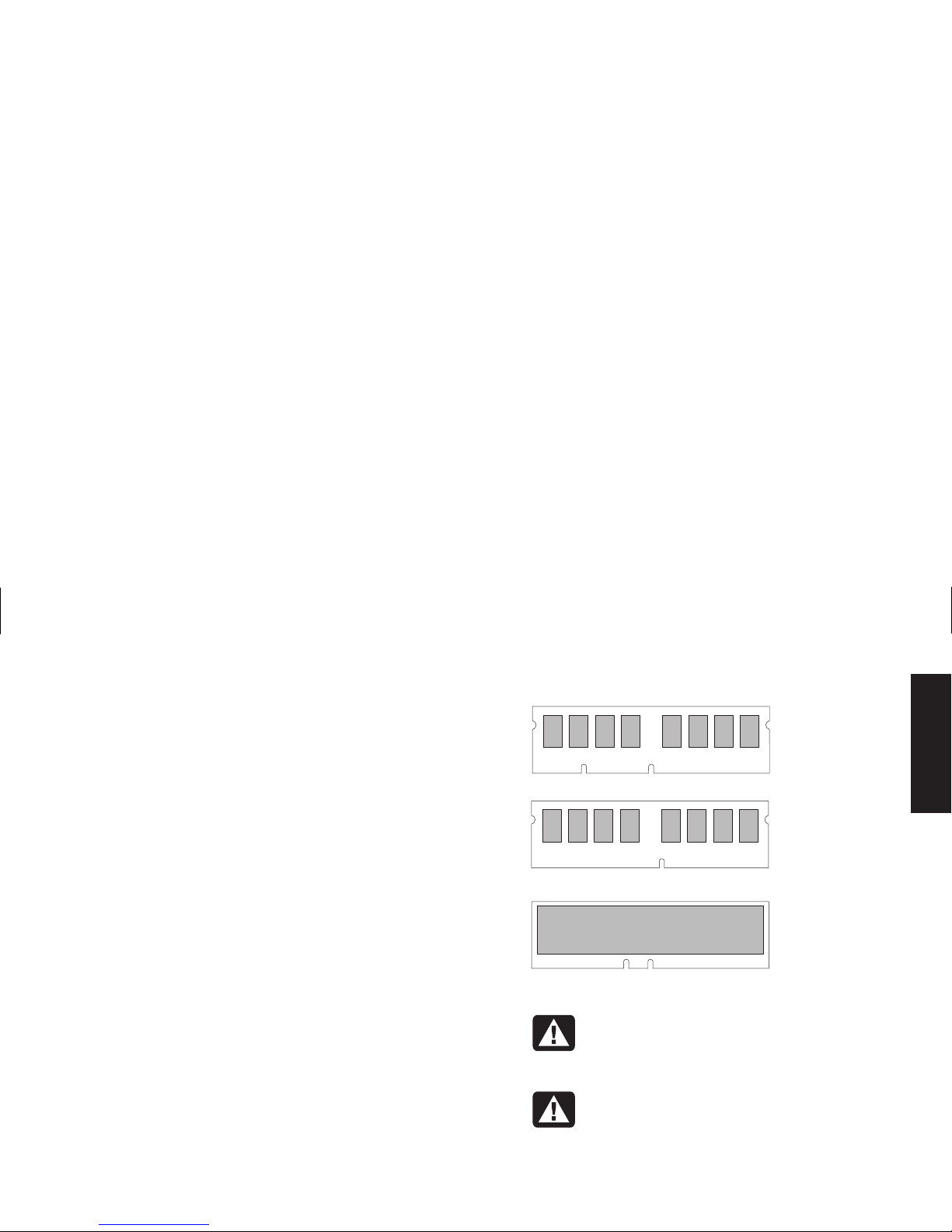
Adding Memory
The motherboard contains sockets for either
DIMMs (dual in-line memory modules), DDR
DIMMs (double data rate dual in-line memory
modules), or RIMMs (Rambus in-line memory
modules), depending on which HP Pavilion
model you have. To determine which type of
memory module your HP Pavilion uses, go to the
HP At Home Web site listed in the
Warranty and
License Information
, and look at the online
HP Pavilion technical specifications.
The motherboard contains 168-pin DIMM
sockets, 184-pin DDR DIMM sockets, or 184-pin
RIMM sockets. The exact number of sockets
depends on which model you have.
DIMM
RIMM
DDR DIMM
Warning:
Using the wrong type of
memory module could damage the
system.
Avertissement :
L’utilisation d’un type
inapproprié de module de mémoire peut
endommager votre système.
Page 12

DIMMs
DIMMs must be 168-pin unbuffered SDRAM
(synchronous dynamic random access memory),
compliant with the Intel
®
PC SDRAM Unbuffered
DIMM Specification
. The HP Pavilion ships with
one or more memory modules, but you can
replace the existing memory module(s) with
higher-capacity ones. You can install 64 MB,
128 MB, or 256 MB memory modules in the
computer.
DDR DIMMs
DDR DIMMs must be 184-pin unbuffered DDR
SDRAM (double data rate synchronous dynamic
random access memory). The HP Pavilion ships
with one or more memory modules, but you can
replace the existing memory module(s) with
higher-capacity ones. You can install 64 MB,
128 MB, or 256 MB memory modules in the
computer.
RIMMs
RIMMs must be 184-pin RDRAM (Rambus
dynamic random access memory), non-ECC (nonerror correction checking), compliant with the
Rambus/Intel specification.
The motherboard has four RIMM sockets that are
for a dual-channel configuration. The following
requirements must be met:
3
Rambus signaling level technology permits 600
and 800 MHz transfer rates. The HP Pavilion
uses PC600 or PC800 RDRAM modules.
3
All four RIMM sockets must be filled. If you do
not populate a socket with a RIMM, the empty
socket must be filled with a C-RIMM (continuity
RIMM). Two C-RIMMs are included on the
motherboard.
Note:
A C-RIMM does not contain any memory — it is
only a placeholder card used to close the
memory circuit. C-RIMMs are necessary to
avoid breaking the signal lines, which are a
serial connection in a Rambus interface; this
assures the electrical integrity.
Page 13

English
3
RIMMs work in identical pairs, so they must be
from the same vendor, have the same speed,
and memory size density within each channel
(see the memory table).
3
When C-RIMMs are used to fill empty sockets,
they must be placed in the RIMM A2 and
RIMM B2 sockets. The RIMMs must be inserted
in the RIMM A1 and RIMM B1 sockets.
The following table illustrates the initial
combinations of RIMMs you can use and the
insertion sequence.
Channel 1 Channel 2
Total
Memory
RIMM A1
socket
RIMM A2
socket
RIMM B1
socket
RIMM B2
socket
128 MB 64 MB
RIMM
C-RIMM 64 MB
RIMM
C-RIMM
256 MB 64 MB
RIMM
64 MB
RIMM
64 MB
RIMM
64 MB
RIMM
256 MB 128 MB
RIMM
C-RIMM 128 MB
RIMM
C-RIMM
384 MB 128 MB
RIMM
64 MB
RIMM
128 MB
RIMM
64 MB
RIMM
512 MB 128 MB
RIMM
128 MB
RIMM
128 MB
RIMM
128 MB
RIMM
512 MB 256 MB
RIMM
C-RIMM 256 MB
RIMM
C-RIMM
Installing a Memory Module
1
Turn off the computer and all peripherals.
2
Disconnect the modem/phone cable.
3
Disconnect the power cord and all other
attached cables (such as the keyboard, mouse,
and monitor).
4
Remove the side panel and the fan duct (see
“Removing the Side Panel” on page 4 and
“Removing the Fan Duct” on page 5).
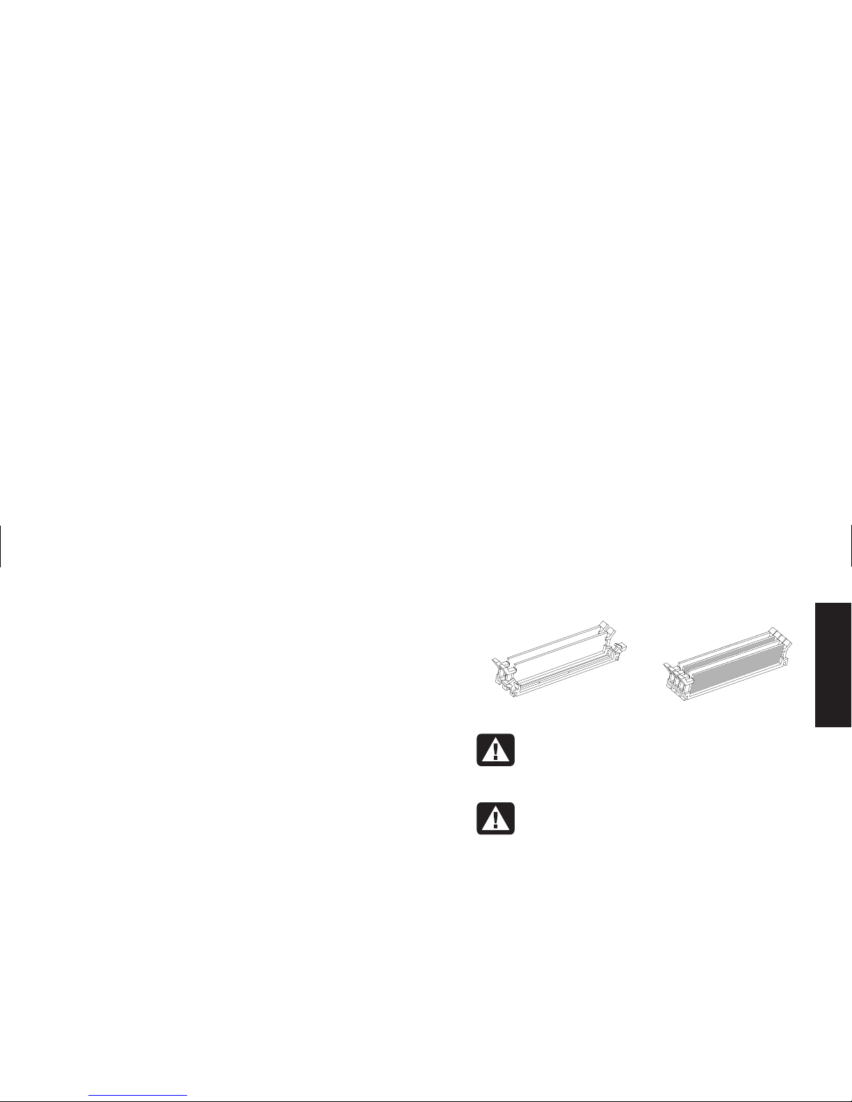
5
Locate the memory sockets on the
motherboard.
DIMM and
RIMM
DDR DIMM
Note:
If all of the memory sockets are filled, you need
to remove one of the memory modules (see
“Removing a Memory Module” on page 11).
6
Move any cabling out of the way, if necessary.
Page 14

7
Push down the two retaining clips on the ends
of the memory socket.
8
Holding the new memory module by its edges
only, remove it from the antistatic packaging.
(Avoid touching the memory chips or the gold
contacts on the module.) The memory module
has one or two small notches on the lower
edge that fit into raised bumps in the memory
socket.
9
Hold the memory module in alignment with the
socket, aligning the notches with the bumps.
DIMM RIMM
DDR DIMM
10
Push straight down on top of the memory
module until it is fully seated in the socket. The
retaining clips on the ends of the socket
automatically lock it into position when the
memory module is fully seated.
To reassemble the computer:
1
If you moved any cabling, restore the cable
connections and routing.
2
Replace the fan duct and the side panel (see
“Closing the Computer” on page 21).
3
Reconnect the power cord and all other
cables.
4
Reconnect the modem/phone cable.
5
Turn on the computer and all peripherals.
Page 15
English
Removing a Memory Module
1
Turn off the computer and all peripherals.
2
Disconnect the modem/phone cable.
3
Disconnect the power cord and all other
attached cables (such as the keyboard, mouse,
and monitor).
4
Remove the side panel and the fan duct (see
“Removing the Side Panel” on page 4 and
“Removing the Fan Duct” on page 5).
5
Locate the memory sockets on the
motherboard.
6
Move any cabling out of the way, if necessary.
7
Push down the two retaining clips on the ends
of the socket until the memory module pops out
of the socket.
DIMM and
RIMM
DDR DIMM
Warning:
Do not pull the memory
module out of the socket. Use the
retaining clips to eject the module.
Avertissement :
Ne tirez pas
directement sur le module de mémoire.
Servez-vous des clips pour l’éjecter.
8
Holding the memory module by its edges only,
lift it away from the socket. Store it in its
antistatic packaging.
To install a new memory module in this socket,
see “Installing a Memory Module” on page 9.
Page 16
Installing Add-In Cards
At some point, you may want to add a PCI or
AGP card to the computer to accommodate a
new component, such as a scanner, or to
upgrade an existing card.
Warning:
Do not overload the system
by installing add-in cards that draw
excessive current. The system is designed
to provide 2 amps (average) of +5 V
power for each board/card in the
computer. The total +5 V current draw in
a fully loaded system (one with all addin card slots filled) must not exceed the
total number of slots multiplied by
2 amps.
Avertissement :
Ne surchargez pas
l’ordinateur en installant des cartes
d’extension qui consomment beaucoup
de courant. L’ordinateur est conçu pour
fournir un courant de 2 ampères (en
moyenne), +5 volts, à chaque carte
installée sur l’ordinateur. La
consommation totale de courant de +5 V
sur un ordinateur entièrement chargé
(dont tous les logements de cartes sont
occupés) ne doit pas excéder le nombre
total de supports multiplié par
2 ampères.
To add or replace an add-in card:
1
Turn off the computer and all peripherals.
2
Disconnect the modem/phone cable.
3
Disconnect the power cord and all other
attached cables (such as the keyboard, mouse,
and monitor).
4
Remove the side panel (see “Removing the
Side Panel” on page 4).
5
Gently lay the computer on its side.
Page 17
English
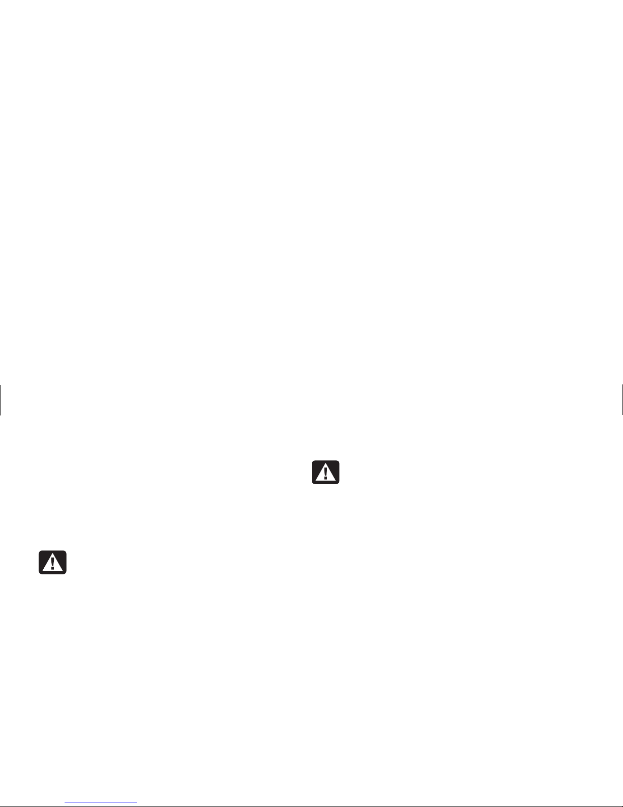
6
To prepare an empty card slot for a new card,
loosen the screw of the expansion slot cover of
the empty slot (E). Remove the expansion slot
cover of the empty slot.
E
Warning:
Be careful of the sharp edges
on the expansion slot cover.
Avertissement :
Soyez prudent, car les
bords du couvercle du support
d’extension sont tranchants.
7
If you are replacing a card, disconnect any
external and/or internal cables attached to the
card.
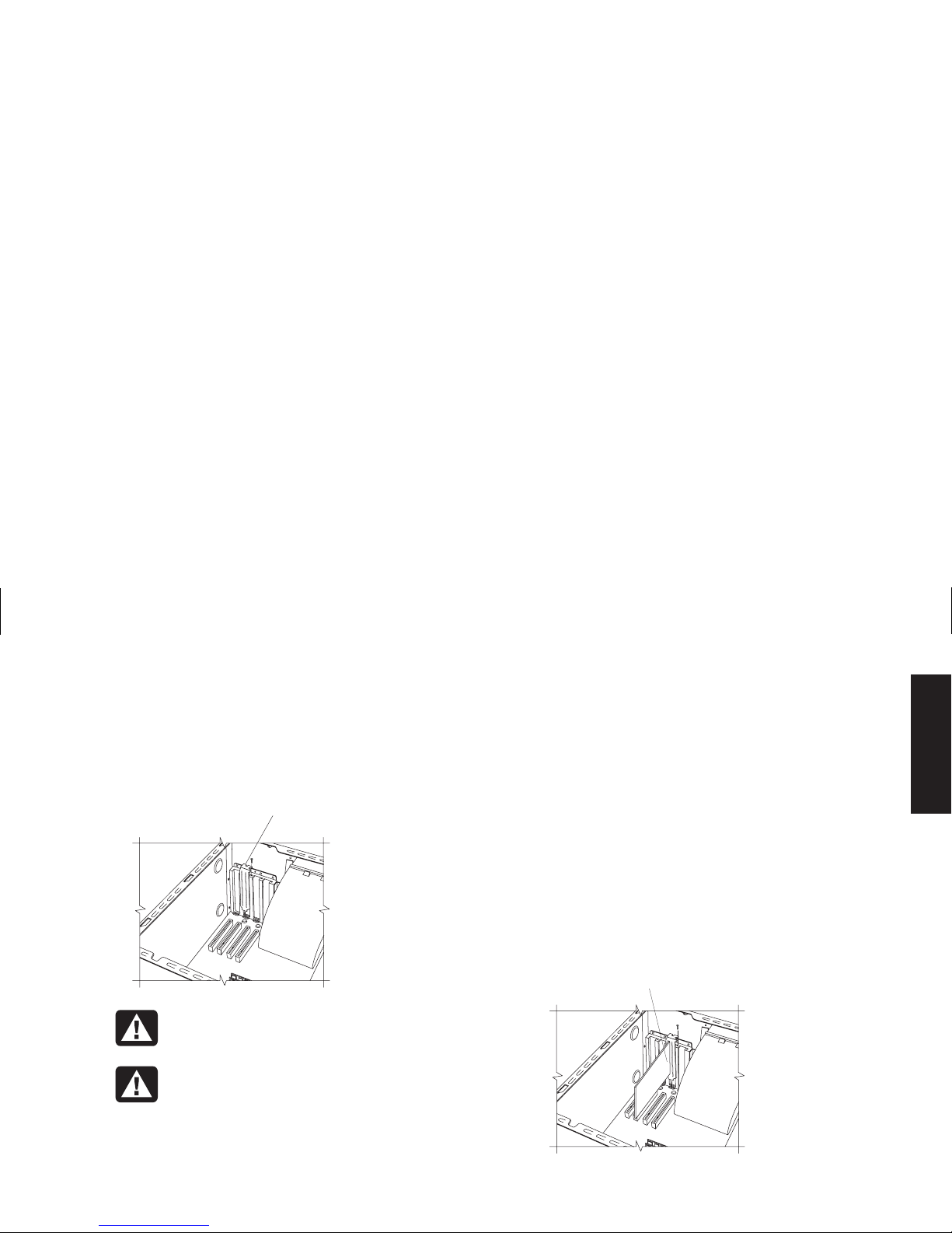
8
Loosen the screw on the bracket of the card
you are replacing (F).
9
Hold the metal bracket and the far top corner
of the card. Carefully remove the card by
pulling the card straight out of the
expansion slot.
10
Insert the new card into the slot and push
straight down. Make sure the card is properly
seated.
11
Attach the screw to secure the card you have
replaced (F).
F
Page 18

To reassemble the computer:
1
Replace the side panel (see “Replacing the
Side Panel” on page 23).
2
Reconnect the power cord and all other
cables.
3
Reconnect the modem/phone cable.
4
Turn on the computer and all peripherals.
5
Install any software drivers supplied by the
card manufacturer.
What Is Plug and Play?
“Plug and Play” describes the ability to add and
remove add-in cards, memory, and peripherals
without any special procedures (such as resetting
jumpers and testing for system conflicts). The
system BIOS (basic input/output system) finds
these components and adds them to the system.
You do not have to run the BIOS setup program.
If the New Card or Device Isn’t
Working
Read through the card manufacturer’s installation
instructions, and recheck all connections,
including those to the card, power supply,
keyboard, and monitor. If the problem still exists,
run the BIOS setup program and load the default
settings, and then save and exit.
Page 19

English
Adding and Removing
Drives
You can install a second hard drive into the
system or replace the existing hard drive. In
addition, you can replace the existing diskette or
optical drives.
Installing a Second Hard Drive
The HP Pavilion has an empty 3.5-inch drive bay
to accommodate an additional hard drive.
1
Turn off the computer and all peripherals.
2
Disconnect the modem/phone cable.
3
Disconnect the power cord and all other
attached cables (such as the keyboard, mouse,
and monitor).
4
Remove the side panel (see “Removing the
Side Panel” on page 4).
5
Remove the drive cage (see “Removing the
Drive Cage” on page 6).
Note:
Make sure the jumper on the new drive is in the
CS (Cable Select) position.
6
Slide the new drive into the empty bay in the
drive cage, until the screw holes align.
7
Install the two screws on the top of the drive
cage and the one screw on the bottom of the
drive cage.
8
Replace the drive cage (see “Replacing the
Drive Cage” on page 21).
9
Attach the power cable to the back of the
drive.
10
Attach the connector marked “Master” on the
IDE ribbon cable to the back of the primary
hard drive. After this primary connection is
attached, twist the remaining part of the cable
marked “Slave” on that same IDE ribbon cable
and connect it to the secondary hard drive.
11
Connect the IDE cable to the motherboard.
Page 20

To reassemble the computer:
1
Replace the side panel (see “Replacing the
Side Panel” on page 23).
2
Reconnect the power cord and all other
cables.
3
Reconnect the modem/phone cable.
4
Turn on the computer and all peripherals.
5
Install any software drivers supplied by the
drive manufacturer.
Removing the Preinstalled Hard
Drive
You need to remove the hard drive from the
chassis if you want to replace it with a highercapacity drive or if you want to safeguard your
data when sending the computer out to be
repaired.
To remove the preinstalled hard drive:
1
Turn off the computer and all peripherals.
2
Disconnect the modem/phone cable.
3
Disconnect the power cord and all other
attached cables (such as the keyboard, mouse,
and monitor).
4
Remove the side panel (see “Removing the
Side Panel” on page 4).
5
Remove the drive cage (see “Removing the
Drive Cage” on page 6).
6
Remove the two screws on the top of the hard
drive and the one screw on the bottom of the
hard drive.
7
Pull the hard drive out, and store the drive and
screws in a safe location.
8
Replace the drive cage and the side panel (see
“Closing the Computer” on page 21).
Page 21
English
Replacing the Diskette Drive
If you need to replace the diskette drive, you can
remove the existing drive and install a new one.
To ensure that the drive fits properly into the
HP Pavilion, be sure to purchase the replacement
diskette drive from HP. Refer to your support path
card for the telephone number of the
HP Customer Care Center.
To remove the existing diskette drive:
1
Turn off the computer and all peripherals.
2
Disconnect the modem/phone cable.
3
Disconnect the power cord and all other
attached cables (such as the keyboard, mouse,
and monitor).
4
Remove the side panel (see “Removing the
Side Panel” on page 4).
5
Remove the drive cage (see “Removing the
Drive Cage” on page 6).
6
Remove the screw (A) on each side of the
diskette drive.
A
Note:
The second screw (A) is on the other side of the
drive cage (not pictured).
7
Pull the diskette drive out.
Page 22

To install a new diskette drive:
1
Slide the diskette drive into the drive cage,
until the two screw holes align.
2
Attach the screws on each side of the drive
cage.
To reassemble the computer:
1
Replace the drive cage (see “Replacing the
Drive Cage” on page 21).
2
Reattach the cables to the back of the hard
and diskette drives.
3
Replace the side panel (see “Replacing the
Side Panel” on page 23).
4
Reconnect the power cord and all other
cables.
5
Reconnect the modem/phone cable.
6
Turn on the computer and all peripherals.
Replacing the Optical Drive
Your computer comes with two optical drives
(CD-ROM, DVD, and/or CD-Writer) that you
can replace or upgrade.
To remove the existing optical drive:
1
Turn off the computer and all peripherals.
2
Disconnect the modem/phone cable.
3
Disconnect the power cord and all other
attached cables (such as the keyboard, mouse,
and monitor).
4
Remove the side panel (see “Removing the
Side Panel” on page 4).
5
Remove the fan duct (see “Removing the
Fan Duct” on page 5).
6
Locate the screws (B and C) on the optical
drive.
Page 23

English
B
C
7
If you are removing the bottom optical drive,
remove the two screws (C) on the drive and
push the drive part way out through the front
of the computer.
Or
If you are removing the top optical drive,
remove the screws (B and C) on both optical
drives and push both drives part way out
through the front of the computer. (This allows
better access to the cables at the back of the
drive.)
8
Remove the cables on the back of the drive
you want to replace.
9
Pull the drive out through the front of the
computer.
To install a new optical drive:
Note:
Make sure the jumper on the new drive is in the
CS (Cable Select) position.
1
Slide the new optical drive through the front of
the computer. Don’t slide the drive in all the
way — you need room to attach the cables.
2
Attach the cables to the back of the optical
drive.
3
Push the drive(s) all the way in, aligning the
screw holes.
4
Attach the screws.
To reassemble the computer:
1
Replace the fan duct and side panel (see
“Closing the Computer” on page 21).
2
Reconnect the power cord and all other
cables.
3
Reconnect the modem/phone cable.
4
Turn on the computer and all peripherals.
5
Install any software drivers supplied by the
drive manufacturer.
Page 24

Replacing the Battery
A lithium battery on the motherboard provides
backup power for the computer’s timekeeping
capability. The battery has an estimated life
expectancy of seven years.
When the battery starts to weaken, the date and
time may be incorrect. If the battery fails, replace
it with a CR2032 lithium battery (3 volt,
220mAH rating) or an equivalent battery.
Warning:
There is danger of explosion
if the battery is incorrectly replaced.
Replace only with the same, or
equivalent, type of battery. Discard used
batteries according to the manufacturer’s
instructions.
Avertissement :
Le remplacement
incorrect de la pile peut provoquer une
explosion. Utilisez uniquement une pile
de même type ou de type équivalent.
Éliminez les piles usées conformément
aux instructions du fabricant.
To replace the battery:
1
Turn off the computer and all peripherals.
2
Disconnect the modem/phone cable.
3
Disconnect the power cord and all other
attached cables (such as the keyboard, mouse,
and monitor).
4
Remove the side panel (see “Removing the
Side Panel” on page 4).
5
If necessary to reach the battery, remove the
drive cage (see “Removing the Drive Cage” on
page 6).
6
If necessary to reach the battery, remove the
fan duct (see “Removing the Fan Duct” on
page 5).
7
If any cards restrict access to the battery:
3
Remove the add-in card bracket. (See
steps 7–9 on page 13.)
3
Remove the cards that are on or near the
battery.
Page 25

English
8
With a pen or screwdriver, press the metal
latch that holds the battery in its socket. The
battery will pop out.
9
Install the new CR2032 battery in the socket,
with the positive (+) side facing up.
To reassemble the computer:
1
Replace any cards that you removed, and then
replace the add-in card bracket.
2
Replace the drive cage, fan duct, and side
panel (see “Closing the Computer” on
page 21).
3
Reconnect the power cord and all other
cables.
4
Reconnect the modem/phone cable.
5
Turn on the computer and all peripherals.
6
Run the BIOS setup program to reset the date
and time.
Closing the Computer
After you have finished installing memory or
drives, inserting or replacing add-in cards, or
changing the battery, you need to replace the
drive cage, the fan duct, and the side panel.
Replacing the Drive Cage
1
Holding the drive cage at a 45-degree angle,
slide the two nubs (A) on the drive cage into
the guides (B) on the chassis.
A
B
Page 26
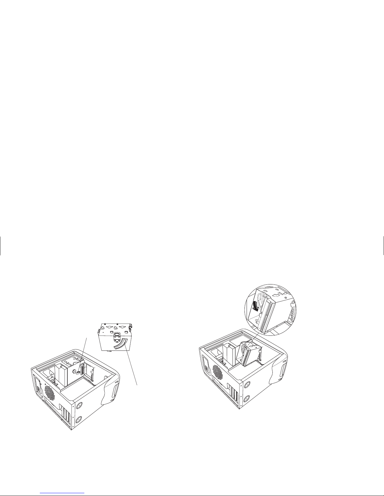
Note:
The second nub (A) is on the other side of the
drive cage (not pictured).
2
Align the track (C) on the drive cage with the
guide (D) on the stationary drive cage.
C
D
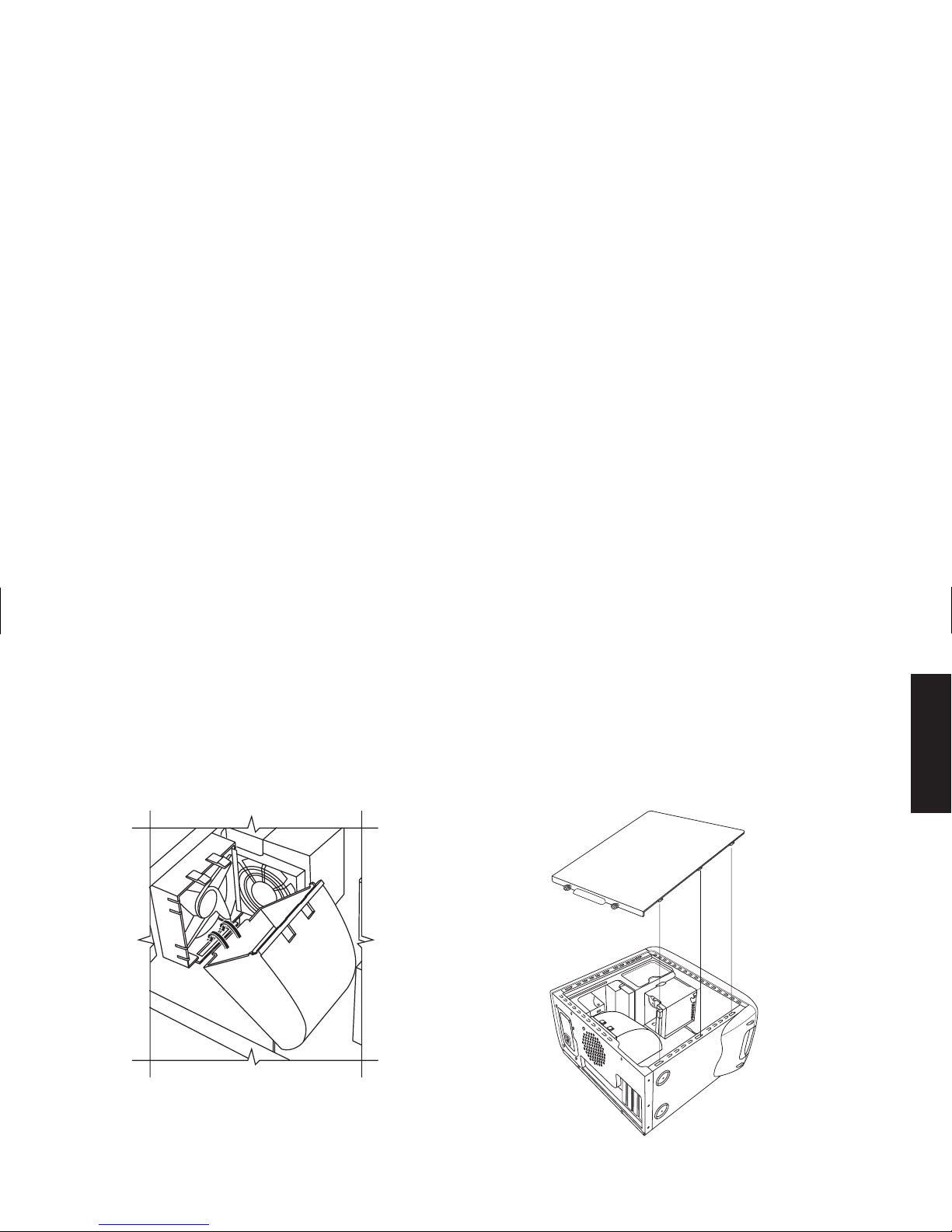
3
Push the removable drive cage firmly against
the stationary cage as you rotate the
removable drive down into position.
4
To make sure that the cage is locked into
position, grasp the drive cage and pull up
forcefully.
Note:
If you are able to remove the drive cage without
pressing the release tab, you didn’t properly
align the track with the guide. Repeat steps 1–4
above.
Page 27
English
Replacing the Fan Duct
1
Holding the fan duct at a 45-degree angle,
align the bottom of the duct with the hole on
the fan holder.
2
Rotate the fan duct into position and make sure
it’s securely locked.
Replacing the Side Panel
1
Lay the side panel on top of the chassis,
aligning the notches on the panel with the
holes on the chassis.
Page 28
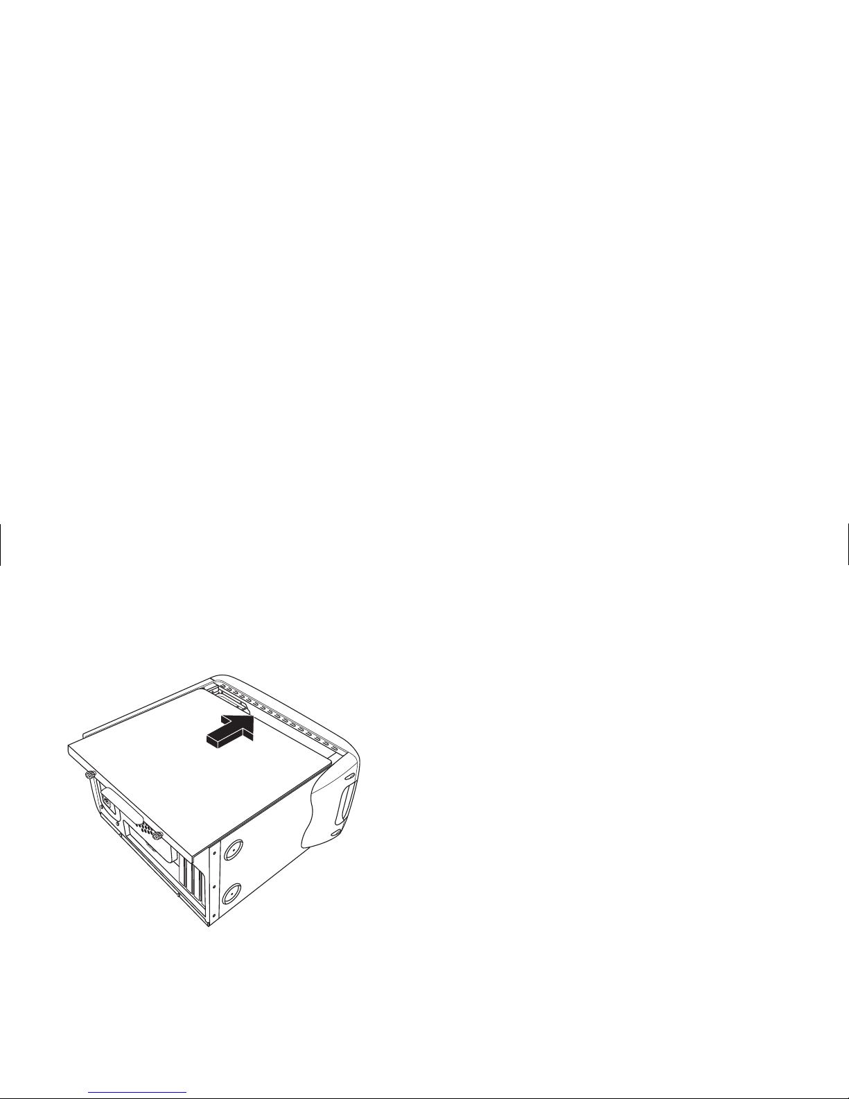
2
Slide the side panel forward until it locks in
place.
3
Tighten the thumbscrews on the side panel.
Page 29

English
Regulatory and Safety
Information
Declaration of Conformity
According to ISO/IEC Guide 22 and EN 45014
Manufacturer’s Name:
Hewlett-Packard Company
Manufacturer’s Address:
10500 Ridgeview Ct.
Cupertino, CA 95015-4010
USA
declares that the product
Product
Name:
HP Pavilion Multimedia Personal Computer System
Model
Number(s):
79XXY, 89XXY (X is any number 0–9, Y is any
alphanumeric character or blank)
XT9ZZ (Z is any number 0–9)
Product
Options:
All
conforms to the following Product Specifications:
Safety:
IEC 60950:1991 + A1, A2, A3, A4
EN 60950:1992 + A1, A2, A3, A4, A11
EMC:
CISPR 22:1997/ EN 55022:1998 Class B
1)
CISPR 24:1997/EN55024:1998
IEC 61000-3-2:1995/EN61000-3-2:1995 + A14 —
Harmonics
IEC 61000-3-3:1994/EN61000-3-3:1995 — Flicker
FCC Title 47 CFR, Part 15 Class B
2)
/ICES-003, Issue 2
AS/NZS 3548:1995+A1+A2:1997/CISPR 22:1993
+A1+A2:1996 Class B
1)
Telecom:
TBR 21:1998, EG201 121:1998
Supplementary Information:
The product herewith complies with the requirements of the following
Directives and carries the CE marking accordingly.
— the EMC Directive 89/336/EEC
— the Low Voltage Directive 73/23/EEC
— the R&TTE Directive 1999/5/EC
1) The Product was tested in a typical configuration with
Hewlett-Packard Personal Computer peripherals.
2) This Device complies with Part 15 of the FCC Rules. Operation
is subject to the following two conditions: (1) this device may
not cause harmful interference, and (2) this device must accept
any interference received, including interference that may
cause undesired operation.
Hardware Quality Engineering Manager
Cupertino, CA, USA May, 2001
For Regulatory Compliance Information ONLY, contact:
Australian
Contact:
Product Regulations Manager
Hewlett-Packard Australia Ltd.
31-41 Joseph Street
Blackburn, Victoria 3130, Australia
European
Contact:
Hewlett-Packard GmbH. HQ-TRE
Herrenberger Straße 110-140
D-71034 Böblingen, Germany
(FAX: + 49-7031-14-3143)
North America
Contact:
Hardware Quality Engineering Manager
Hewlett-Packard, HPD
10500 Ridgeview Ct.
Cupertino, CA 95015-4010
USA
(Phone: 408-343-5000)
Page 30

FCC Regulatory and Safety
Information (USA Only)
Federal Communications Commission (FCC) Radio
Frequency Interference Statement
Warning:
This equipment has been tested
and found to comply with the limits for a
Class B digital device, pursuant to Part 15
of the FCC Rules. These limits are designed
to provide reasonable protection against
harmful interference in a residential
installation. This equipment generates,
uses, and can radiate radio frequency
energy and, if not installed and used in
accordance with the instructions,
may cause harmful interference to radio
communications. However, there is no
guarantee that interference will not occur
in a particular installation. If this
equipment does cause harmful
interference to radio or television
reception, which can be determined by
turnin
g
the equipment off and on, the user
is encouraged to correct the interference
by one or more of the following measures:
3
Reorient or relocate the receiving
antenna.
3
Increase the separation between the
equipment and the receiver.
3
Connect the equipment into an outlet that
is on a circuit different from the receiver.
3
Consult the dealer or an experienced
radio/TV technician for help.
Hewlett-Packard’s system RFI and
Radiated Immunity tests were conducted
with HP-su
pp
orted peripheral devices and
HP-shielded cables, such as those you
receive with your system. Changes or
modifications not expressly approved by
Hewlett-Packard could void the user’s
authority to operate the equipment. To
comply with the limits for an FCC Class B
computing device, always use shielded
signal cables and the power cord supplied
with this unit.
Page 31

English
Consumer Information and FCC
Requirements
Telephone Connection
3
This equipment complies with Part 68 of the Federal
Communications Commission rules. These rules permit this
device to be directly connected to the telephone network.
Standardized jacks are used for these connections. This
equipment should not be used on party lines or coin lines.
3
If this device is malfunctioning, it may also cause harm to
the telephone network; this device should be disconnected
until the source of the problem can be determined and
until it has been repaired. If this is not done, the
telephone company may temporarily disconnect your
service.
3
The telephone company may make changes in its
technical operations and procedures. If such changes
affect the compatibility or use of this device, the telephone
company is required to give adequate notice of the
changes.
3
If the telephone company requests information on what
equipment is connected to their lines, inform them of:
a
The telephone number this unit is connected to
b
The ringer equivalence number
c
The USOC jack required: RJ-11C
d
The FCC Registration Number
Items (b) and (c) are indicated on the label. The ringer
equivalence number (REN) is used to determine how
many devices can be connected to your telephone line.
In most areas, the sum of the RENs on any one line should
not exceed five (5.0). If too many devices are attached,
they may not ring properly.
3
In the event of equipment malfunction, Hewlett-Packard or
an authorized HP Personal Computer Dealer Repair
Center should perform all repairs. It is the responsibility of
users requiring service to report the problem to HP’s
Home Products Division, or to one of our authorized
agents. Service can be obtained by calling the
HP Customer Care Center at 208-323-4663
(United States).
Page 32

Statement of Fax Branding
The Consumer Protection Act of 1991 makes it unlawful for
any person to use a computer or other electronic device to
send any message via telephone fax machine, unless it
clearly contains: a margin at the top or bottom of each
transmitted page or on the first page of the transmission, the
date and time it is sent, identification of the business or other
entity, or individual sending the message, the telephone
number of the sending machine or such business, entity, or
individual.
ENERGY STAR Compliance
Hewlett-Packard Pavilion PCs and monitors marked with the
ENERGY STAR
logo comply with the U.S. Environmental
Protection Agency’s
ENERGY STAR
guidelines for energy
efficiency. For information on changing power management
features, refer to “Putting the Computer into Standby and
Hibernation Mode” in the
Quick Start Guide
.
ENERGY STAR
is a U.S. registered service mark of the
United States Environmental Protection Agency.
Canada Department of
Communications (DOC) Notice
Telephone Connection
The Canada Department of Communications label identifies
certified equipment. This certification means that the
equipment meets certain telecommunications network
protective, operational, and safety requirements. The
department does not guarantee the equipment will operate
to the user’s satisfaction.
Before installing this equipment, the user should ensure it
is permissible to connect it to the facilities of the local
communications company. The equipment must be installed
using an acceptable method of connection. In some cases,
the company’s inside wiring associated with a single line
individual service may be extended by means of a certified
connector assembly (telephone extension cord). The
customer should be aware that compliance with the above
conditions may not prevent degradation of service in some
situations.
Repairs to certified equipment should be made by an
authorized Canadian maintenance facility designated by the
supplier. Any repairs or alterations made by the user to this
equipment, or equipment malfunctions, may give the
telecommunications company cause to request that the user
disconnect the equipment.
Page 33

English
Users should ensure, for their own protection, that the
electrical ground connections of the power utility, telephone
lines, and internal metallic water pipe systems, if present,
are connected together. This precaution may be particularly
important in rural areas.
Warning:
Users should not attempt to
make such connections themselves, but
should contact the appropriate electrical
inspection authority or electrician, as
appropriate.
Avertissement :
L’utilisateur ne devrait pas
tenter de faire ces connexions lui-même
mais devrait utiliser les services
de l’organisme approprié d’inspection des
installations électri
q
ues ou d’un électricien,
selon le cas.
Warning:
The Load Number .9 assigned to
each terminal device denotes the
percentage of the total load to be
connected to a telephone loop; this is used
by the device to prevent overloading. The
termination on a loop may consist of any
combination of devices, sub
j
ect only to the
requirement that the sum of the Load
Numbers does not exceed 100.
Avertissement :
La valeur de charge .9
attribuée à chaque élément terminal
indique le pourcentage de la charge totale
pouvant être connecté à une boucle
télé
p
honique. Cette valeur est utilisée pour
éviter les surchar
g
es. La terminaison d’un
e
boucle peut être constituée d’une
combinaison quelconque d’équipements,
dans la mesure où la somme des valeurs
de charge ne dépasse pas 100.
DOC Statement (Canada Only)
This Class B digital apparatus meets all requirements of the
Canadian Interference-Causing Equipment Regulations.
Cet appareil numérique de la classe B respecte toutes les
exigences du Règlement sur le matériel brouilleur du
Canada.
Austel Statement (Australia Only)
When setting the number of automatic redials for the
modem, ensure the following: The number of automatic
redials that the modem performs should be limited to a
maximum of 9 redials plus the original call. If the above
retries are unsuccessful, no further attempts should be made
to the same number for a minimum period of five minutes.
Page 34

Warning:
Failure to set the modem, and
any communication software used with
the modem, to the values contained in the
listing will result in the modem being
operated in a non-compliant manner.
Consequently, there would be no permit in
force for this equipment, and the
Telecommunications Act 1991 prescribes a
penalty of A$12,000 for the connection of
non-permitted equipment.
Australia/New Zealand Telecom
Statement
Your modem has been granted an Austel Permit for use in
Australia and a New Zealand Telecom Telepermit for use in
New Zealand. In each country, special conditions apply to
the settings and features of your modem. Failure to observe
these conditions might result in heavy penalties being
applied (up to A$12,000.00 in Australia).
Warning:
For safety reasons, only connect
equipment with a telecommunications
compliance label. This includes customer
equipment previously labeled, permitted
or certified.
The grant of a Permit/Telepermit in no way indicates the
telecom agency’s acceptance of responsibility for the correct
operation of that device under all operating conditions. In
particular, the higher speeds at which this modem is
capable of operating depend on a specific network
implementation which is only one of many ways of
delivering high-quality voice telephone to customers. Failure
to operate should not be reported as a fault to Telecom or
Austel.
In addition to satisfactory line conditions, a modem can
work properly only if:
3
It is compatible with the modem at the other end of the
call, and
3
The application using the modem is compatible with the
application at the other end of the call; for example,
accessing the Internet requires suitable software in
addition to a modem.
This equipment shall not be used in any manner which could
constitute a nuisance to other customers.
The setting and features discussed below influence how your
modem reacts with the telephone network. If changes from
the default values are made, then it is possible that
unwanted signals or interference may be generated, your
modem might dial wrong numbers or suffer from a reduced
level of performance. We strongly recommend that the
settings are not changed under any circumstances or the
Permit/Telepermit may become invalid.
Page 35

English
Initialization
Many communications programs react to the default settings
when started. This is usually achieved by the ATZ command
and initializes your modem for correct operation. Many
programs are developed for worldwide use and generally
use the ATZ command; however, some programs have builtin modem configuration utilities and these should not be
used unless you can confirm that they are compatible with
Australian and New Zealand requirements.
If your program does not use the ATZ command to initialize,
but instead sends a complex string of characters, then it must
be configured to send the correct string for Australia and
New Zealand. The correct initialization string is (spaces
should not be entered; they are to make it easier to read):
AT &F T /N6 S6=3 S7=45 % L=7 &Y0 &W0
Once you have entered this command string, it is written to
the internal memory of the modem and the default
configuration.
Dialing
The modem supports both pulse and tone dialing in
Australia and only tone dialing in New Zealand. New
Zealand users please note that if pulse dialing is selected,
then wrong numbers will be dialed, as the reverse
numbering scheme is not supported. There are several dial
string modifiers referred to in the main users’ manual, and
we suggest that they be used with caution to avoid problems
when making calls.
Automatic Answering
To conform with Austel and Telecom New Zealand
requirements when configuring your modem for autoanswering, please do not set the SO register to values less
than 2 or greater than 10 (Note: ATSO-O will disable autoanswering). Pre-configured software should be checked and
changed as necessary. These settings ensure:
3
A person calling your modem will hear a short burst of
ringing before the modem answers. This confirms that the
call has been successfully switched through the network.
3
Caller identification information (which occurs between
the first and second ring cadences) is not destroyed.
Automatic Multiple Dialing Attempts
Most communication software can be configured to make
automatic dialing attempts to a telephone number that is
busy or not answering (automatic redial function). The
maximum number of all attempts that can be made in one
sequence must not exceed the numbers shown in the
following table. If your program makes continuous automatic
dialing attempts or more than the number in the table, and it
cannot be changed, an alternative program must be used or
automatic dialing disabled. There is no limit for manually
initiated dialing attempts.
Page 36

Country
Number of
attempts per
sequence
Pauses
between
attempts
(seconds)
Pauses
between
sequences
(minutes)
Australia
New Zealand1010
3
60
30
60
Bell Compatible Operation
Bell compatible mode should not be used. Nearly all
modems use CCITT mode because Bell mode is limited to a
maximum speed of 300 or 1200 BPS, and some network
interference problems may arise due to line signaling
requirements.
Parallel Telephones
If you find that you regularly experience line noise or other
interference when using your modem, we suggest
disconnecting other telephones from the line. Some
telephones may place a load across the telephone line when
not in use, which adversely affects the performance of your
modem.
If disconnecting parallel telephones reduces the interference,
then it may be necessary to have the telephone(s) repaired
or replaced.
Warning:
(
New Zealand users only) Please
note that operation of this modem on the
same line as telephones or other
e
quip
ment with audible ringing devices, o
r
automatic ringing detectors, may cause
“bell tinkle” or false tripping of the
ringing detector.
If this occurs, do not contact Telecom Faults
Service. Also, please note that the power
consumed from the telephone line by this
modem may not provide for the effective
transfer of a call to or from other
equipment connected to the same line.
Connecting to Other Equipment
There are two telephone line sockets in your modem,
marked LINE and PHONE. The telephone line is connected
to the LINE socket, and other equipment, such as the
telephone, is connected to the PHONE socket. Please note
that Austel permitted/NZ Telepermitted equipment only may
be connected to the PHONE socket.
Miscellaneous
There are many commands referred to in the main user’s
manual. Incorrect use of some of these commands may
render your modem inoperative or severely degrade its
performance. Generally, it is best not to change any setting
unless you are an experienced user.
Page 37

English
Should you accidentally alter any settings, and are unsure
how to undo the changes, it is best to completely re-initialize
your modem by giving the AT&F command (the only time
you should use this command) and then manually enter the
initialization string of point A. This will reset your modem to
the correct settings for Australia and New Zealand.
Voice Features
If your new modem is fitted with voice features, then it is
illegal in Australia and New Zealand to use it with software
that allows recording of telephone conversations. (It can be
used as an answering machine, mail box center,
telemarketing system, and so forth, but it cannot be used to
record a “live” conversation between telephone users.) If
your software supports telephone conversation recording
(perhaps called Two-way Recording), then this feature must
be disabled in the program configuration.
EMI Statement (European Union Only)
This is a class B product. In a domestic environment, this
product may cause radio interference in which case the user
may be required to take adequate measures.
European Telephone Network
Declaration (European Union Only)
The product herewith complies with the requirements of the
R&TTE Directive 1999/5/EC (Annex II) and carries the CE
marking accordingly. However, due to differences between
the individual PSTNs provided in different countries, the
approval does not, of itself, give an unconditional assurance
of successful operation on every PSTN network termination
point. In the event of problems, you should contact your
equipment supplier in the first instance.
European Network Compatibility
Declarations (European Union
Only)
This equipment has been designed to work with analogue
DTMF Networks (TBR-21 compliant).
This equipment may have internetworking difficulties in
PSTN networks that only support Pulse Dialing. Please
consult with your network operator for further assistance.
Page 38

UK Compliance Information
This modem is approved by the Secretary of State at the
Department of Trade and Industry for connection to a single
exchange line of the public switch telephone network run by
certain licensed public telecommunication operators or
systems connected thereto. (Direct exchange lines only, not
shared service or 1-1 carrier systems.)
This modem is also suitable for connection to Private
Automatic Branch Exchanges (PABXs) which return
secondary proceed indication.
If this modem is to be used with a PBX which returns
secondary proceed indication, no more than two pauses of
four seconds duration each should be inserted between the
initial PSTN access digit and the number to be dialed. This
is to avoid interference to the PTO network.
If this modem is to be used with a PBX which has extension
wiring owned by BT, connection of the modem to the PBX
can only be carried out by BT; or, by the authorized
maintainer of the PNX unless the authorized maintainer has
been given 14 days written notice that the connection is to
be made by another person, and that period of notice has
expired.
This modem is suitable for use only on telephone lines
provided with Loop-Disconnect or Multi-Frequency Dialing
facilities.
Users of this modem are advised that the approval is for
connection to the PSTN via the telephone line interference
supplied with it. Connection of a modem to the PSTN by any
other means will invalidate the approval.
There is no guarantee of correct working in all
circumstances. Any difficulties should be referred to your
supplier.
Some network operators require that intended users of their
network request permission to connect and for the
installation of an appropriate socket.
Ringer Equivalence Number
The ringer equivalence number (REN) of this modem is 1.
REN is a guide to the maximum number of apparatuses that
can be simultaneously connected to one telephone line. The
REN value of each apparatus is added together, and should
not exceed 4. Unless otherwise marked, a telephone can be
assumed to have a REN value of 1.
Approved Usage
This modem is approved only for the following:
3
Storage of telephone numbers for retrieval by a
predetermined code
3
Detection of initial proceed indication
3
Automatic calling/Automatic answering
3
Ton e de te c ti on
Page 39

English
3
Operation in the absence as a secondary proceed
indication
3
Loudspeaking facility
This modem is NOT suitable for use as an extension to a
payphone.
This modem is not approved for connection to UK private
speechband services.
This modem does not support the automatic redial function.
Any other usage will invalidate the approval of your
modem, if, as a result, it then ceases to conform to the
standards against which approval was granted.
The approval of this modem is INVALIDATED if the
apparatus is subject to modification in any material way not
authorized by the BABT or if it is used with or connected to
external software that has not been formally accepted by
BABT.
Storage of Numbers
It is advisable to check the telephone numbers stored in your
modem immediately after programming.
In order to prevent the misdirection of class and network
interference, please ensure that all manually programmed
telephone numbers are correctly entered.
The number you enter to dial may optionally contain a
PAUSE character (a comma) to allow this modem to operate
with a PABX. Each comma gives a two-second delay.
Additional Safety Information
This product has not been evaluated for connection to an
“IT” power system (an AC distribution system with no direct
connection to earth, according to IEC 60950).
AC Power Safety Warning
Proper Electrical Connection (Norway and
Sweden only)
Adversel:
Apparatet må kun tilkoples
jordet stikkontakt.
Varnin g!
Apparaten skall anslutas till
jordat uttag när den ansluts till ett
nätverk.
Warning:
Install the computer near an AC
outlet. The AC power cord is your
HP Pavilion’s main AC disconnectin
g
device
and must be easily accessible at all times.
For your safety, the power cord provided
with your system has a grounded plug.
Always use the power cord with a
properly grounded wall outlet, to avoid
the risk of electrical shock.
Page 40

Warning:
Your system is provided with a
voltage select switch for use in a 115 or
230 Vac power system. The voltage select
switch has been pre-set to the correct
voltage setting for use in the particular
country where it was initially sold.
Changing the voltage select switch to the
incorrect position can damage your PC
and void any implied warranty.
Warning:
To reduce the possibility of an
electric shock from the tele
p
hone network,
plug your computer into the AC outlet
before connecting it to the telephone line.
Also, disconnect the telephone line before
unplugging your computer from the
AC power outlet.
Warning:
Always disconnect the modem
cord from the telephone system before
installing or removing your computer
cover.
Warning:
Do not operate the computer
with the cover removed.
Warning:
The power supply is not userserviceable. To prevent damage to the
power supply, have a qualified person
repair or replace it. All other components
are user-serviceable.
Warning:
Electrostatic discharge (ESD) can
damage disk drives, add-in cards, and
other components. If an ESD station is not
available, wear a wrist stra
p
attached to
a
metal part of the computer. Place cards on
a conductive foam pad or inside the card
wrapper, if possible, but never on the card
wrapper.
Page 41

English
Warning:
For your safety, always unplug
the system from its power source and from
any telecommunications systems (such as
p
hone lines), networks, or modems before
performing any of the procedures
described in this guide. Failure to do so
may result in personal injury or equipment
damage. Hazardous voltage levels are
inside the power supply and modem of
this product.
Avertissement :
Installez l’ordinateur à
proximité d’une prise c.a. Le cordon
d’alimentation c.a. est le principal dispositif
de déconnexion de l’ordinateur HP Pavilion
et doit toujours être facilement accessible.
Pour votre sécurité, le cordon
d’alimentation fourni avec votre système
possède une prise avec mise à la terre.
Branchez toujours le cordon dans une
prise murale avec mise à la terre, afin
d’éviter les risques d’électrocution.
Avertissement :
Votre système est doté
d’un commutateur de sélection de tension
(115 ou 230 volts c.a.). Ce commutateur a
été
p
lacé sur la tension appropriée pour le
pays dans lequel l’équipement est
initialement vendu. Mettre le commutateur
à la mauvaise position peut endommager
l’ordinateur et annuler toute garantie
implicite.
Avertissement :
Pour réduire les risques de
choc électrique en provenance du réseau
téléphonique, branchez votre ordinateur
dans une
p
rise c.a. avant de le connecter à
une ligne téléphonique. En outre,
déconnectez votre ligne téléphonique
avant de débrancher votre ordinateur de
la prise c.a.
Avertissement :
Débranchez la carte
modem du réseau téléphonique avant
d’installer ou d’enlever le couvercle de
votre ordinateur.
Page 42

Avertissement :
N’utilisez pas l’ordinateur
lorsque le capot est enlevé.
Avertissement :
Le bloc d’alimentation
n’est pas réparable par l’utilisateur. Pour
éviter d’endommager le bloc
d’alimentation, confiez-le à un technicien
p
our réparation ou remplacement. Tous les
autres composants peuvent être changés
ou réparés par l’utilisateur.
Avertissement :
Des décharges
électrostatiques peuvent endommager les
unités de disque, cartes d’extension et
autres composants. Si vous ne disposez
pas d’une station de protection contre les
décharges électrostatiques, portez un
bracelet antistatique relié à une partie
métallique de l’ordinateur. Placez les
cartes sur un tapis en mousse conducteur
ou dans leur emballa
g
e, mais ne les posez
jamais sur leur emballage.
Avertissement :
Pour plus de sécurité,
débranchez toujours le système de sa
source d’alimentation, de tout système de
télécommunications (comme les lignes
téléphoniques), des réseaux et des
modems avant d’exécuter l’une des
procédures décrites dans ce chapitre.
Si vous ne respectez pas ces consignes,
vous risquez de vous blesser et de causer
des dommages matériels. Des niveaux de
tension dan
g
ereux se trouvent à l’intérieur
du bloc d’alimentation et du modem de ce
produit.
Lithium Battery Caution
Warning:
The PC uses a lithium battery,
type CR2032. There is danger of an
explosion if the battery is incorrectly
replaced. Replace only with the same, or
equivalent, type recommended by the
manufacturer. Dispose of used batteries
according to the manufacturer’s
instructions.
Page 43

English
Warnung:
In diesem PC wird eine
Lithiumbatterie des Typs CR2032
verwendet. Wenn Sie beim Austauschen
dieser Batterie nicht sach
g
emäß vorgehen,
besteht Explosionsgefahr. Ersetzen Sie die
Batterie nur durch eine Batterie desselben
Typs oder eines entsprechenden, vom
Hersteller empfohlenen Typs. Befolgen Sie
bei der Entsorgung gebrauchter Batterien
die Anweisungen des Herstellers.
Avertissement :
L’ordinateur utilise une
pile au lithium de type CR2032.
Le remplacement incorrect de la pile peut
provoquer une explosion. Utilisez
uniquement une pile de même type ou de
type équivalent. Éliminez les piles usées
conformément aux instructions du
fabricant.
Varnin g!
PC:n använder ett litiumbatteri,
typ CR2032. Vid felaktigt batteribyte
föreligger risk för explosion. Ersätt bara
med samma eller liknande batterityp,
rekommenderad av tillverkaren. Gör dig
av med batterierna enligt tillverkarens
instruktioner.
Advarsel:
PCen bruker et litiumbatteri av
typen CR2032. Dersom det brukes feil
batteri, kan det oppstå fare for
eksplosjon. Du må bare bruke
batteritypen som anbefales av
produsenten, eller tilsvarende batterier.
Følg produsentens instruksjoner for
kassering av brukte batterier.
Varoitus:
PC käyttää CR2032-tyyppistä
litiumparistoa. Räjähdyksen vaara, jos
paristo vaihdetaan väärin. Vaihda vain
samanlaiseen tai vastaavaan valmistajan
suosittelemaan paristoon. Käytetyt
paristot täytyy hävittää valmistajan
ohjeiden mukaisesti.
Waarschuwing:
De PC gebruikt een
lithiumbatterij, type CR2032. Er bestaat
explosiegevaar als de batterij niet goed
wordt vervangen. Vervang de batterij
uitsluitend door een batterij van hetzelfde
of een gelijkwaardig type, dat wordt
aanbevolen door de leverancier. Behandel
gebruikte batterijen volgens de
aanwijzingen van de leverancier.
Page 44

Laser Safety Statement
Class 1 LED Product
The CD-ROM and DVD drives contain a laser system and
are classified as a “Class 1 Laser Product” under a U.S.
Department of Health and Human Services (DHHS)
Radiation Performance standard according to the Radiation
Control for Health and Safety Act of 1968.
Should the unit ever require maintenance, contact an
authorized service location.
Warning:
Use of controls, adjustments, or
performance procedures other than those
specified in this
Upgrading and Servicing
the PC
guide may result in hazardous
radiation exposure. To prevent direct
exposure to laser beam, do not try to
open the enclosure of the CD-ROM or DVD.
Avertissement : L’utilisation de
commandes, réglages ou procédures de
performance autres que ceux spécifiés
dans le guide Mise à niveau et entretien
de l’ordinateur peut entraîner une
exposition à des radiations. Afin d’éviter
une exposition directe au rayon laser, ne
tentez pas d’ouvrir le boîtier du lecteur de
CD-ROM ou DVD.
TV Antenna Connectors Protection
External Television Antenna Grounding
If an outside antenna or cable system is connected to the
product, be sure the antenna or cable system is electrically
grounded so as to provide some protection against voltage
surges and built-up static charges. Article 810 of the
National Electrical Code, ANSI/NFPA 70, provides
information with regard to proper electrical grounding of the
mast and supporting structure, grounding of the lead-in wire
to an antenna-discharge unit, size of grounding conductors,
location of antenna-discharge unit, connection to grounding
electrodes, and requirements for the grounding electrode.
Lightning Protection
For added protection of any Hewlett-Packard product during
a lightning storm, or when it is left unattended and unused
for long periods of time, unplug the product from the wall
outlet and disconnect the antenna or cable system. This will
prevent damage to the product from lightning and power
line surges.
Page 45

English
2
1
1
2
3
4
5
6
7
3
4
5
6
7
Antenna Grounding
Antenna Grounding
Grounding Component
Electric Service Equipment
Ground Clamps
Ground Clamp
Grounding Conductors (NEC Section 810-21)
Antenna Discharge Unit (NEC Section 810-20)
Antenna Lead in Wire
Power Service Grounding Electrode System
(NEC Art 250, Part H)
Reference
Power Lines
An outside antenna system should not be located in the
vicinity of overhead power lines or other electric light or
power circuits, or where it can fall into such power lines or
circuits.
Warning:
When installing an outside
antenna system, extreme care should be
taken to keep from touching such power
lines or circuits as contact with them could
be fatal.
Avertissement :
Lorsque vous installez une
antenne extérieure, vous devez faire
attention à ne pas toucher ces lignes et
circuits d’alimentation, tout contact
pouvant être mortel.
Operating Specifications
Electrical ratings
Models 79XXY/ 89XXY/ XT9ZZ —
100–127 Vö/200–240 Vö,
4/2 A, 50/60 Hz
Operating
temperature
5° to 35° C
Storage
temperature
–40° to 70° C
Operating
humidity
15 to 80% @ 26° C
Storage humidity
90% @ 65° C (non-condensing)
Operating altitude
0–2286 m
Storage altitude
0–4572 m
Page 46

Index
A
add-in cards
installing, 12
troubleshooting, 14
AGP cards, adding, 12
B
battery, replacing, 20
D
DDR DIMMs
installing and removing, 7
DIMMs, installing and removing, 7
diskette drive
replacing, 17
drive cage
removing, 6
replacing, 21
F
fan duct
removing, 5
replacing, 23
H
hard drive
installing, 15
removing, 16
I
installing components
memory, 7
M
memory
adding, 7
DDR DIMMs, 8
DIMMs, 8
installing, 9
removing, 11
RIMMs, 8
memory module
installing, 9
O
optical drive
replacing, 18
P
panel
removing, 4
replacing, 23
PCI cards, adding, 12
Plug and Play, 14
R
regulatory and safety information,
25
RIMMs, installing and removing, 7
S
safety information, 35
T
troubleshooting, add-in cards, 14
Page 47

Français
mise à niveau et entretien
de l’ordinateur
Page 48

Les informations apparaissant dans ce document sont sujettes à
modification sans préavis.
La société Hewlett-Packard
®
n’offre aucune garantie concernant ce
matériel, notamment une éventuelle garantie tacite de
commercialisation ou de convenance à un usage quelconque.
La société HP ne peut être tenue responsable de quelque erreur
dans ce document ni d’éventuels dommages secondaires ou
indirects liés à la vente, aux performances ou à l’utilisation de ce
matériel.
La société HP n’assume aucune responsabilité quant à l’utilisation
ou à la fiabilité de ses logiciels sur un matériel qui n’est pas fourni
par HP.
Ce document contient des informations en propriété exclusive
protégées par copyright. Tous les droits sont réservés. Aucune
partie de ce document ne peut être photocopiée, reproduite ou
traduite dans une autre langue sans l’autorisation écrite préalable
de HP.
Hewlett-Packard Company
Home Products Division
P.O. Box 4010
Cupertino, CA 95015-4010
États-Unis
© Hewlett-Packard Company, 2001. Tous droits réservés.
Hewlett-Packard est une marque déposée de Hewlett-Packard
Company aux États-Unis et dans d’autres pays.
Les autres marques ou noms de produits sont des marques de
commerce appartenant à leurs propriétaires respectifs.
Page 49

Français
Caractéristiques du l’ordinateur
personnel HP Pavilion .......................... 1
Ouverture de l’ordinateur .................... 2
Avant de commencer......................................... 3
Enlèvement du panneau latéral........................... 4
Retrait du conduit du ventilateur.......................... 5
Enlèvement de la cage de lecteurs ...................... 6
Ajout de mémoire ................................ 8
Modules DIMM ................................................ 9
Modules DDR DIMM ......................................... 9
Modules RIMM................................................. 9
Installation d’un module de mémoire................. 10
Retrait d’un module de mémoire ....................... 12
Installation de cartes d’extension ....... 13
Qu’est-ce que le Plug and Play
?....................... 15
Si la nouvelle carte ou le nouveau périphérique
ne fonctionne pas ........................................... 15
Ajout et retrait de lecteurs.................. 16
Installation d’un second disque dur................... 16
Retrait du disque dur d’origine......................... 17
Remplacement du lecteur de disquette............... 18
Remplacement du lecteur optique ..................... 19
Remplacement de la pile.................... 21
Fermeture de l’ordinateur .................. 23
Remise en place de la cage de lecteurs............. 23
Remise en place du conduit du ventilateur ......... 24
Remise en place du panneau latéral ................. 25
Informations sur la réglementation et la
sécurité ............................................. 26
Homologation ENERGY STAR .......................... 29
Fiche technique .............................................. 44
Index ................................................ 45
Table des matières
Page 50

Page 51

Français
Caractéristiques du
l’ordinateur personnel
HP Pavilion
Un compartiment de rangement des disques
compacts (A) se trouve en haut du châssis.
Conservez-y les CD-ROM fournis avec
l’ordinateur afin de pouvoir les trouver
rapidement au cas où vous devriez réinstaller
des applications.
Pour connecter des composants sur l’avant de
l’ordinateur, soulevez le volet (B), et branchez
les câbles dans les connecteurs appropriés.
B
A
Remarque :
Le bloc d’alimentation électrique est
préréglé pour le pays où vous avez acheté votre
ordinateur HP Pavilion. Si vous déménagez dans un
autre pays, n’oubliez pas de vérifier la tension
électrique disponible dans votre nouvelle résidence.
Page 52

Ouverture de l’ordinateur
Warning:
The HP Pavilion is heavy; be
sure to use ergonomically correct lifting
procedures when moving the computer.
Avertissement :
L’ordinateur
HP Pavilion est lourd ; respectez les règles
d’ergonomie lorsque vous le déplacez.
Warning:
Electrostatic discharge (ESD)
can damage disk drives, add-in cards,
and other components. If an ESD station is
not available, wear a wrist strap attache
d
to a metal part of the computer. Place
cards on a conductive foam pad or inside
the conductive wrapper they came in; do
not place the cards on top of the wrapper.
Avertissement :
Les décharges
électrostatiques peuvent endommager les
unités de disque, cartes d’extension et
autres composants. Si vous ne disposez
pas d’une station de protection contre les
décharges électrostatiques, portez un
bracelet antistatique relié à une partie
métallique de l’ordinateur. Placez les
cartes sur un tapis en mousse conducteur
ou dans leur emballage, mais ne les
posez jamais sur l’emballage.
Warning:
Do not operate the system
with the cover removed. Always replace
the cover before turning on the system.
Avertissement :
N’utilisez pas le
système lorsque son capot est ouvert.
Remettez toujours le capot en place avant
de mettre le système sous tension.
Page 53

Français
Avant de commencer
Lisez attentivement les directives suivantes avant
d’effectuer une mise à niveau de votre
ordinateur ou une quelconque réparation :
3
Dans ces procédures, il est entendu que vous
connaissez la terminologie générale associée
aux ordinateurs personnels, ainsi que les
règles de sécurité et de conformité applicables
pour l’utilisation et la modification
d’équipements électroniques.
3
Tenez un journal pour enregistrer les numéros
de modèle et de série de l’ordinateur, les
options installées ainsi que d’autres
informations sur le système. Lorsque vous en
aurez besoin, il sera plus facile de consulter
ce journal que d’ouvrir et examiner
l’ordinateur.
3
HP vous conseille d’utiliser un bracelet
antistatique et un tapis en mousse conducteur
lorsque vous ouvrez l’ordinateur.
3
Avant d’exécuter l’une des procédures décrites
dans ce chapitre, déconnectez l’ordinateur de
toute liaison de télécommunication, réseau ou
modem, puis de la source d’alimentation. Sans
quoi, vous risqueriez de vous blesser ou
d’endommager l’ordinateur.
Remarque :
Débranchez le câble de
modem/téléphone avant de débrancher le
cordon d’alimentation.
Vous devrez retirer le panneau latéral pour
accéder aux composants internes de l’ordinateur.
Warning:
Please read the “
Additional
Safety Information”
located at the end of
this document before installing and
connecting your system to the electrical
power system.
Avertissement :
Prière de lire les
consignes additionnelles de sécurité
à la
fin de ce document avant d’installer et
d’alimenter votre système informatique.
Page 54

Enlèvement du panneau latéral
Vous devrez retirer le panneau latéral pour
ajouter de la mémoire, des cartes d’extension,
installer ou retirer des lecteurs, ou pour changer
la pile.
1
Éteignez l’ordinateur et tous ses
périphériques.
2
Débranchez le câble du modem/téléphone.
3
Débranchez le cordon d’alimentation et tous
les autres câbles reliés à l’ordinateur, tels que
ceux du clavier, de la souris, et du moniteur.
4
Desserrez les deux vis à droite du panneau
arrière. La première fois que vous desserrez les
vis, un tournevis à tête plate est nécessaire (ces
vis ne s’enlèvent pas et restent sur le panneau
latéral. Pensez à les resserrer lorsque vous
aurez terminé).
Page 55

Français
5
Placez-vous derrière l’ordinateur et posez une
main sur le haut du châssis.
6
De l’autre main, tirez sur la poignée (A) pour
faire bouger le panneau dans votre direction,
jusqu’à ce qu’il n’aille pas plus loin.
A
7
Soulevez le panneau et retirez-le. Mettez le
panneau de côté.
Retrait du conduit du ventilateur
Vous devrez retirer le conduit du ventilateur pour
accéder à certains composants de la carte mère.
Remarque :
Vérifiez que l’ordinateur est hors tension.
Le câble du modem/téléphone et le cordon
d’alimentation doivent être débranchés de
l’ordinateur.
1
Retirez le panneau latéral (voir
Enlèvement du
panneau latéral
en page 4).
2
Posez délicatement l’ordinateur sur le côté.
3
Dégagez le conduit du ventilateur (B) en
poussant sur les deux onglets (C). Vous pouvez
pousser avec vos doigts ou avec un stylo.
Page 56

C
B
4
Faites tourner le conduit du ventilateur et
retirez-le du châssis.
Enlèvement de la cage de lecteurs
L’ordinateur HP Pavilion possède deux cages de
lecteurs. La cage supérieure fixe contient le(s)
lecteur(s) de disque compact. La cage inférieure
contient le lecteur de disquette et l’unité de disque
dur. Elle est amovible. Il est possible que vous
deviez enlever cette cage inférieure pour accéder
à divers composants internes ou pour ajouter un
disque dur ou le remplacer.
Remarque :
Vérifiez que l’ordinateur est hors tension.
Le câble du modem/téléphone et le cordon
d’alimentation doivent être débranchés de
l’ordinateur.
1
Retirez le panneau latéral (voir
Enlèvement du
panneau latéral
en page 4).
2
Posez délicatement l’ordinateur sur le côté.
3
Enlevez le conduit du ventilateur (voir
Retrait du
conduit du ventilateur
en page 5).
Page 57

Français
4
Débranchez le cordon d’alimentation et le
câble IDE derrière le lecteur de disquette et les
unités de disque dur. Notez toutes les
connexions avant de débrancher les câbles.
5
Poussez sur la languette de dégagement de la
cage de lecteurs (D).
D
6
Tenez la languette en bas, faites pivoter la
cage vers le haut et sortez-la.
Page 58

Ajout de mémoire
La carte mère est équipée de supports convenant
à des modules DIMM, DDR DIMM ou RIMM, en
fonction du modèle de votre ordinateur
HP Pavilion. Pour connaître le type de module
utilisé par votre modèle, accédez au site
HP Pavilion indiqué dans la section de
renseignements du la garantie et la licence et
consultez la fiche technique de votre modèle.
La carte mère comporte des supports DIMM à
168 broches, des supports DDR DIMM à 184
broches ou des supports RIMM à 184 broches.
Le nombre exact de supports dépend du modèle
utilisé.
DIMM
RIMM
DDR DIMM
Warning:
Using the wrong type of
memory module could damage the
system.
Avertissement :
L’utilisation d’un type
inapproprié de module de mémoire peut
endommager votre système.
Page 59

Français
Modules DIMM
Les modules DIMM doivent être du type SDRAM,
168 broches sans mémoire tampon, conformes
à la norme Intel
®
PC SDRAM Unbuffered DIMM
.
Votre ordinateur HP Pavilion est fourni avec un
ou plusieurs modules de mémoire, que vous
pouvez remplacer par d’autres modules de
capacité supérieure. Votre système accepte les
capacités de 64 Mo, 128 Mo et 256 Mo.
Modules DDR DIMM
Les modules DDR DIMM doivent être du type
SDRAM, 184 broches, sans mémoire tampon.
L’ordinateur HP Pavilion est fourni avec un ou
plusieurs modules de mémoire, que vous pouvez
remplacer par d’autres modules de capacité
supérieure. Votre système accepte les capacités
de 64 Mo, 128 Mo et 256 Mo.
Modules RIMM
Les modules RIMM doivent être du type RDRAM,
184 broches non ECC, conformes à la norme
Rambus/Intel.
La carte mère est équipée de quatre supports
RIMM conçus pour une configuration à double
canal. Les conditions requises sont les suivantes :
3
L’utilisation de la technologie Rambus permet
d’obtenir des taux de transfert de 600 et
800 MHz. L’ordinateur HP Pavilion utilise des
modules RDRAM PC600 ou PC800.
3
Les quatre supports doivent être remplis. Un
support ne contenant pas de module RIMM doit
contenir un module C-RIMM (continuity RIMM —
module de continuité RIMM). La carte mère est
fournie avec deux modules C-RIMM.
Page 60

Remarque :
Un module C-RIMM ne contient pas de
mémoire et ne sert qu’à fermer le circuit en
l’absence de modules RIMM. Les modules
C-RIMM permettent d’éviter l’interruption des
lignes de signaux (connexion série dans une
interface Rambus) et assurent l’intégrité des
circuits électriques.
3
Les modules RIMM fonctionnent par paires
identiques, ils doivent donc provenir du même
fournisseur, avoir la même vitesse et la même
densité de taille mémoire sur chaque canal (voir
le tableau de mémoire).
3
Lorsque vous utilisez des C-RIMM pour remplir
des supports vides, vous devez les placer dans
les supports RIMM A2 et RIMM B2. Les modules
RIMM doivent être placés dans les supports
RIMM A1 et RIMM B1.
Le tableau suivant présente les combinaisons
initiales de modules RIMM utilisables, ainsi que
l’ordre d’insertion.
Canal 1 Canal 2
Mémoire
totale
Douille
RIMM A1
Douille
RIMM A2
Douille
RIMM B1
Douille
RIMM B2
128 Mo RIMM
64 Mo
C-RIMM RIMM
64 Mo
C-RIMM
256 Mo
RIMM
64 Mo
RIMM
64 Mo
RIMM
64 Mo
RIMM
64 Mo
256 Mo RIMM
128 Mo
C-RIMM RIMM
128 Mo
C-RIMM
384 Mo RIMM
128 Mo
RIMM
64 Mo
RIMM
128 Mo
RIMM
64 Mo
512 Mo RIMM
128 Mo
RIMM
128 Mo
RIMM
128 Mo
RIMM
128 Mo
512 Mo
RIMM
256 Mo
C-RIMM
RIMM
256 Mo
C-RIMM
Installation d’un module de
mémoire
1
Éteignez l’ordinateur et tous ses périphériques.
2
Débranchez le câble du modem/téléphone.
3
Débranchez le cordon d’alimentation et tous les
autres câbles reliés à l’ordinateur, tels que ceux
du clavier, de la souris, et du moniteur.
Page 61

Français
4
Retirez le panneau latéral et le conduit du
ventilateur (voir
Enlèvement du panneau
latéral
en page 4 et
Retrait du conduit du
ventilateur
en page 5).
5
Repérez les supports de mémoire sur la
carte mère.
DIMM et
RIMM
DDR DIMM
Remarque :
Si tous les supports à mémoire sont
remplis, vous devrez retirer un des modules de
mémoire (voir
Retrait d’un module de mémoire
en page 12).
6
Au besoin, écartez les câbles qui vous gênent.
7
Appuyez sur les deux clips de fixation aux
extrémités du support de mémoire.
8
Retirez le nouveau module de mémoire de son
emballage antistatique en le tenant par les
bords uniquement. (Évitez de toucher les puces
de mémoire ou les contacts dorés du module.)
Le module comporte une ou deux petites
encoches sur le bord inférieur qui s’enclenchent
dans les bords surélevés du support de
mémoire.
9
Alignez le module de mémoire sur le support
en faisant coïncider les encoches avec les
bords surélevés.
DIMM RIMM
DDR DIMM
10
Appuyez sur le module de mémoire jusqu’à ce
qu’il soit bien enfoncé dans le support. Les clips
de fixation situés aux extrémités du support
s’enclenchent automatiquement lorsque le
module de mémoire est entièrement inséré.
Page 62

Pour remonter l’ordinateur :
1
Si vous avez déplacé des câbles, remettez-les
en place et rebranchez-les.
2
Remettez le conduit du ventilateur et le
panneau latéral en place (voir
Fermeture de
l’ordinateur
en page 23).
3
Rebranchez le cordon d’alimentation et tous
les autres câbles.
4
Rebranchez le câble du modem/téléphone.
5
Mettez l’ordinateur et tous ses périphériques
sous tension.
Retrait d’un module de mémoire
1
Éteignez l’ordinateur et tous ses
périphériques.
2
Débranchez le câble du modem/téléphone.
3
Débranchez le cordon d’alimentation et tous
les autres câbles reliés à l’ordinateur, tels que
ceux du clavier, de la souris, et du moniteur.
4
Retirez le panneau latéral et le conduit du
ventilateur (voir
Enlèvement du panneau
latéral
en page 4 et
Retrait du conduit du
ventilateur
en page 5).
5
Repérez les supports de mémoire sur la
carte mère.
6
Au besoin, écartez les câbles qui vous gênent.
7
Appuyez sur les deux clips de fixation aux
extrémités du support pour en extraire le
module.
DIMM et
RIMM
DDR DIMM
Warning:
Do not pull the memory
module out of the socket. Use the
retaining clips to eject the module.
Avertissement :
Ne tirez pas
directement sur le module de mémoire.
Servez-vous des clips pour l’éjecter.
8
Dégagez le module de mémoire de son support
en le tenant par les bords uniquement. Placez
le module dans son emballage antistatique.
Pour installer un nouveau module de mémoire
dans ce support, consultez
Installation d’un
module de mémoire
en page 10.
Page 63

Français
Installation de cartes
d’extension
Il deviendra peut-être nécessaire d’ajouter une
carte PCI ou AGP à votre ordinateur pour
installer un nouveau composant, tel qu’un
scanner, ou pour mettre à niveau une carte
existante.
Warning:
Do not overload the system
by installing add-in cards that draw
excessive current. The system is designed
to provide 2 amps (average) of +5 V
power for each board/card in the
computer. The total +5 V current draw in
a fully loaded system (one with all add-in
card slots filled) must not exceed the total
number of slots multiplied by 2 amps.
Avertissement :
Ne surchargez pas
l’ordinateur en installant des cartes
d’extension à trop forte consommation.
L’ordinateur est conçu pour fournir 2
ampères (en moyenne), +5 volts, à
chaque carte installée sur l’ordinateur. La
consommation totale de +5 V sur un
ordinateur entièrement chargé (dont tous
les supports de cartes sont occupés) ne
doit pas excéder le nombre total de
supports multiplié par 2 ampères.
Pour ajouter ou remplacer une carte d’extension :
1
Éteignez l’ordinateur et tous ses périphériques.
2
Débranchez le câble du modem/téléphone.
3
Débranchez le cordon d’alimentation et tous les
autres câbles reliés à l’ordinateur, tels que ceux
du clavier, de la souris, et du moniteur.
4
Retirez le panneau latéral (voir
Enlèvement du
panneau latéral
en page 4).
5
Posez délicatement l’ordinateur sur le côté.
Page 64

6
Afin de préparer un support vide pour une
nouvelle carte, desserrez la vis du couvercle
du support vide (E). Retirez le couvercle du
support vide.
E
Warning:
Be careful of the sharp edges
on the expansion slot cover.
Avertissement :
Soyez prudent, car les
bords du couvercle du support
d’extension sont tranchants.
7
Si vous remplacez une carte, déconnectez les
câbles internes ou externes qui sont reliés à la
carte.
8
Desserrez la vis sur la patte métallique du
support de la carte que vous désirez
remplacer (F).
9
En tenant la patte métallique et l’angle
supérieur de la carte, dégagez doucement la
carte en la tirant bien droite hors du support.
10
Insérez et enfoncez la nouvelle carte dans le
support. Vérifiez que la carte est correctement
placée.
11
Installez la vis pour fixer la carte que vous
venez d’insérer (F).
F
Page 65

Français
Pour remonter l’ordinateur :
1
Remettez en place le panneau latéral (voir
Remise en place du panneau latéral
en
page
25).
2
Rebranchez le cordon d’alimentation et tous
les autres câbles.
3
Rebranchez le câble du modem/téléphone.
4
Mettez l’ordinateur et tous ses périphériques
sous tension.
5
Installez les pilotes fournis par le fabricant de
la carte.
Qu’est-ce que le Plug and Play
?
L’expression Plug and Play désigne la fonction qui
permet d’ajouter et de supprimer des cartes
d’extension, des modules mémoire et des
périphériques sans avoir à suivre de procédure
spéciale (comme la réinitialisation de cavaliers ou
le test de conflits système). Le BIOS (système
d’entrée-sortie de base) de votre ordinateur
détecte ces composants et les ajoute au système. Il
n’est pas nécessaire d’exécuter le programme de
configuration du BIOS.
Si la nouvelle carte ou le nouveau
périphérique ne fonctionne pas
Consultez les directives d’installation du fabricant
de la carte, vérifiez à nouveau toutes les
connexions, y compris les connexions à la carte,
au bloc d’alimentation, au clavier et à l’écran. Si
le problème persiste, exécutez le programme de
configuration du BIOS, chargez les paramètres
par défaut, enregistrez-les et quittez le
programme.
Page 66

Ajout et retrait de lecteurs
Sur ce système, vous pouvez installer un
deuxième disque dur ou remplacer celui qui est
déjà installé. En outre, vous pouvez remplacer le
lecteur de disquette et le lecteur optique.
Installation d’un second
disque dur
L’ordinateur HP Pavilion possède un support vide
de 3,5 pouces pour vous permettre d’installer un
autre disque dur.
1
Éteignez l’ordinateur et tous ses
périphériques.
2
Débranchez le câble du modem/téléphone.
3
Débranchez le cordon d’alimentation et tous
les autres câbles reliés à l’ordinateur, tels que
ceux du clavier, de la souris, et du moniteur.
4
Retirez le panneau latéral (voir
Enlèvement du
panneau latéral
en page 4).
5
Enlevez la cage de lecteurs (voir
Enlèvement de
la cage de lecteurs
en page 6).
Remarque :
Assurez-vous que le cavalier du
nouveau lecteur est sur la position CS (cable
select).
6
Faites glisser le nouveau lecteur dans
l’ouverture de la cage de lecteurs, de façon à
aligner les trous des vis.
7
Installez les deux vis sur le dessus de la cage
de lecteurs, ainsi que la vis en-dessous.
8
Remettez en place la cage de lecteurs (voir
Remise en place de la cage de lecteurs
en
page
23).
9
Reliez le cordon d’alimentation au dos du
lecteur.
10
Branchez le connecteur « Master », du câble
plat IDE sur l’arrière du disque dur principal.
Lorsque cette connexion de base est faite,
enroulez la partie « Slave » (esclave) du même
câble plat IDE et connectez-la au disque dur
secondaire.
Page 67

Français
11
Connectez le câble IDE à la carte mère.
Pour remonter l’ordinateur :
1
Remettez en place le panneau latéral (voir
Remise en place du panneau latéral
en
page 25).
2
Rebranchez le cordon d’alimentation et tous
les autres câbles.
3
Rebranchez le câble du modem/téléphone.
4
Mettez l’ordinateur et tous ses périphériques
sous tension.
5
Installez les pilotes fournis par le fabricant du
lecteur.
Retrait du disque dur d’origine
Vous devrez enlever le disque dur du châssis
pour le remplacer par un autre ayant une
capacité supérieure ou pour protéger vos
données avant d’envoyer votre ordinateur à un
atelier de réparation.
Pour retirer le disque dur d’origine :
1
Éteignez l’ordinateur et tous ses périphériques.
2
Débranchez le câble du modem/téléphone.
3
Débranchez le cordon d’alimentation et tous les
autres câbles reliés à l’ordinateur, tels que ceux
du clavier, de la souris, et du moniteur.
4
Retirez le panneau latéral (voir
Enlèvement du
panneau latéral
en page 4).
5
Enlevez la cage de lecteurs (voir
Enlèvement de
la cage de lecteurs
en page 6).
6
Enlevez les deux vis sur le dessus du disque
dur, ainsi que la vis en-dessous.
7
Sortez le disque dur, puis rangez le disque et
les vis dans un endroit sûr.
8
Replacez la cage de lecteurs et le panneau
latéral (voir
Fermeture de l’ordinateur
en
page 23).
Page 68

Remplacement du lecteur de
disquette
Si vous devez remplacer le lecteur de disquette,
vous pouvez enlever l’ancien et en installer un
nouveau. Pour vous assurer que le nouveau
lecteur soit compatible avec votre ordinateur
HP Pavilion, achetez-le chez HP. Pour connaître
le numéro de téléphone du centre de Service
Clientèle HP, consultez votre carte d’assistance
technique.
Pour retirer le lecteur de disquette original :
1
Éteignez l’ordinateur et tous ses
périphériques.
2
Débranchez le câble du modem/téléphone.
3
Débranchez le cordon d’alimentation et tous
les autres câbles reliés à l’ordinateur, tels que
ceux du clavier, de la souris, et du moniteur.
4
Retirez le panneau latéral (voir
Enlèvement du
panneau latéral
en page 4).
5
Enlevez la cage de lecteurs (voir
Enlèvement de
la cage de lecteurs
en page 6).
6
Retirez la vis (A) sur chaque côté du lecteur de
disquette.
A
Remarque :
La deuxième vis (A) est sur l’autre côté
de la cage de lecteurs (non illustrée).
7
Retirez le lecteur de disquette.
Page 69

Français
Pour installer un nouveau lecteur de disquette :
1
Faites glisser le lecteur de disquette dans la
cage de lecteurs, jusqu’à ce que les deux
trous de vis soient alignés.
2
Installez les vis sur chaque côté de la cage de
lecteurs.
Pour remonter l’ordinateur :
1
Remettez en place la cage de lecteurs (voir
Remise en place de la cage de lecteurs
en
page 23).
2
Rebranchez les câbles à l’arrière du disque
dur et du lecteur de disquette.
3
Remettez le panneau latéral en place (voir
Remise en place du panneau latéral
en
page 25).
4
Rebranchez le cordon d’alimentation et tous
les autres câbles.
5
Rebranchez le câble du modem/téléphone.
6
Mettez l’ordinateur et tous ses périphériques
sous tension.
Remplacement du lecteur optique
Votre ordinateur est équipé de deux lecteurs
optiques (CD-ROM, DVD et/ou CD-Writer) que
vous pouvez remplacer ou mettre à niveau.
Pour retirer le lecteur optique original :
1
Éteignez l’ordinateur et tous ses périphériques.
2
Débranchez le câble du modem/téléphone.
3
Débranchez le cordon d’alimentation et tous les
autres câbles reliés à l’ordinateur, tels que ceux
du clavier, de la souris, et du moniteur.
4
Retirez le panneau latéral (voir
Enlèvement du
panneau latéral
en page 4).
5
Enlevez le conduit du ventilateur (voir
Retrait du
conduit du ventilateur
en page 5).
Page 70

6
Repérez les vis (B et C) sur le lecteur optique.
B
C
7
Si vous désirez enlever le lecteur optique
inférieur, enlevez les deux vis (C) sur le lecteur
et poussez sur le lecteur pour le sortir
partiellement sur l’avant de l’ordinateur.
— Ou —
Si vous enlevez le lecteur optique supérieur,
enlevez les vis (B et C) sur les deux lecteurs et
poussez sur les deux lecteurs pour les sortir
partiellement sur le devant du lecteur (vous
aurez ainsi plus de facilité à accéder aux
câbles derrière le lecteur).
8
Enlevez les câbles derrière le lecteur que vous
désirez remplacer.
9
Sortez le lecteur par le devant de l’ordinateur.
Pour installer un nouveau lecteur optique :
Remarque :
Assurez-vous que le cavalier du
nouveau lecteur est sur la position CS (cable
select).
1
Faites glisser le nouveau lecteur optique dans le
boîtier par le devant de l’ordinateur. Ne
poussez pas le lecteur jusqu’au fond, vous
aurez besoin d’espace pour installer les câbles.
2
Installez les câbles derrière le lecteur optique.
3
Enfoncez le ou les lecteurs au maximum, en
alignant les trous de vis.
4
Remettez les vis en place.
Page 71

Français
Pour remonter l’ordinateur :
1
Remettez le conduit du ventilateur et le
panneau latéral en place (voir
Fermeture de
l’ordinateur
en page 23).
2
Rebranchez le cordon d’alimentation et tous
les autres câbles.
3
Rebranchez le câble du modem/téléphone.
4
Mettez l’ordinateur et tous ses périphériques
sous tension.
5
Installez les pilotes fournis par le fabricant du
lecteur.
Remplacement de la pile
Une pile au lithium posée sur la carte mère assure
l’alimentation de secours pour la fonction
d’horloge de l’ordinateur. La pile a une durée de
vie prévue de sept ans.
Lorsqu’elle commence à faiblir, la date et l’heure
peuvent devenir incorrectes. Vous devrez alors la
remplacer par une pile neuve au lithium CR2032
(3 volts, puissance nominale 220 mAH) ou de
type équivalent.
Warning:
There is danger of explosion
if the battery is incorrectly replaced.
Replace only with the same, or
equivalent, type of battery. Discard used
batteries according to the manufacturer’s
instructions.
Avertissement :
Le remplacement
incorrect de la pile peut provoquer une
explosion. Utilisez uniquement une pile d
e
même type ou de type équivalent. Jetez
les piles usagées conformément aux
instructions du fabricant.
Page 72

Pour remplacer la pile :
1
Éteignez l’ordinateur et tous ses
périphériques.
2
Débranchez le câble du modem/téléphone.
3
Débranchez le cordon d’alimentation et tous
les autres câbles reliés à l’ordinateur, tels que
ceux du clavier, de la souris, et du moniteur.
4
Retirez le panneau latéral (voir
Enlèvement du
panneau latéral
en page 4).
5
Si cela est nécessaire pour atteindre la pile,
enlevez la cage de lecteurs (voir
Enlèvement
de la cage de lecteurs
en page 6).
6
Si cela est nécessaire pour atteindre la pile,
enlevez le conduit du ventilateur (voir
Retrait
du conduit du ventilateur
en page 5).
7
Si des cartes empêchent d’accéder à la pile :
3
Enlevez le support de cartes d’extension
(voir les opérations 7–9 en page 14).
3
Retirez les cartes proches de la pile.
8
Avec un stylo ou un tournevis, appuyez sur le
verrou métallique qui retient la pile dans son
support. La pile s’éjectera.
9
Posez la nouvelle pile CR2032 dans le support,
le côté positif (+) vers le haut.
Pour remonter l’ordinateur :
1
Remettez les cartes en place et fermez le
support de cartes d’extension.
2
Replacez la cage de lecteur, le conduit du
ventilateur et le panneau latéral (voir
Fermeture
de l’ordinateur
en page 23).
3
Rebranchez le cordon d’alimentation et tous les
autres câbles.
4
Rebranchez le câble du modem/téléphone.
5
Mettez l’ordinateur et tous ses périphériques
sous tension.
6
Exécutez le programme de configuration du
BIOS pour programmer la date et l’heure.
Page 73

Français
Fermeture de l’ordinateur
Après avoir installé des modules mémoire ou des
lecteurs, inséré ou remplacé des cartes
d’extension ou changé la pile, vous devrez
remettre en place la cage de lecteurs, le conduit
du ventilateur et le panneau latéral.
Remise en place de la cage de
lecteurs
1
Tenez la cage de lecteurs inclinée sur 45°,
puis faites glisser les deux bosses (A) de la
cage de lecteurs dans les rainures de guidage
(B) du châssis.
A
B
Remarque :
La deuxième bosse (A) est sur l’autre
côté de la cage de lecteurs (non illustrée).
2
Alignez le rail (C) de la cage de lecteurs avec
la rainure de guidage (D) sur la cage de
lecteurs fixe.
C
D
3
Appuyez fermement la cage de lecteurs
amovible contre la cage fixe en même temps
que vous la faites tourner pour l’installer.
Page 74

4
Pour vous assurer que la cage est bloquée en
position, saisissez-la et essayez de tirer vers le
haut avec énergie.
Remarque :
Si vous arrivez à enlever la cage de
lecteurs sans appuyer sur la languette
d’ouverture, vous avez mal aligné le rail avec
la rainure de guidage. Répétez les opérations
1 à 4 ci-dessus.
Remise en place du conduit du
ventilateur
1
Tenez le conduit du ventilateur à un angle de
45°, en alignant la base du conduit avec le
trou dans le support du ventilateur.
2
Faites tourner le conduit pour l’insérer à sa
place, en vous assurant qu’il est solidement
bloqué.
Page 75

Français
Remise en place du panneau
latéral
1
Posez le panneau sur le dessus du châssis et
alignez les encoches du panneau avec les
trous du châssis.
2
Faites glisser le panneau vers l’avant jusqu’à ce
qu’il se bloque en place.
3
Serrez les vis sur le côté du panneau.
Page 76

Informations sur la
réglementation et la
sécurité
Déclaration de conformité
Conformément aux normes ISO/IEC Manuel 22 et
EN 45014
Nom du fabricant :
Hewlett-Packard Company
Adresse du fabricant:
10500 Ridgeview Ct.
Cupertino, CA 95015-4010,
États-Unis
déclare que le produit
Nom du
produit :
Ordinateur personnel multimédia HP Pavilion
Modèle(s) :
79XXY, 89XXY (X représente n’importe quel
chiffre entre 0 et 9, tandis que Y correspond à un
espace ou à un caractère alphanumérique)
XT9ZZ (Z représente un chiffre entre 0 et 9)
Options du
produit :
Toutes
Respecte les spécifications suivantes :
Sécurité :
IEC 60950:1991 + A1, A2, A3, A4
EN 60950:1992 + A1, A2, A3, A4, A11
CEM :
CISPR 22:1997/ EN55022:1998 Classe B
1)
CISPR 24:1997/ EN55024:1998
IEC 61000-3-2:1995/EN61000-3-2:1995 + A14 —
Harmoniques
IEC 61000-3-3:1994/EN61000-3-3:1995 —
Scintillement
FCC Titre 47 CFR, Partie 15 Classe B
2)
/ICES-003,
Édition 2
AS/NZS 3548:1995 + A1 + A2:1997/CISPR
22:1993 + A1 + A2:1996 Classe B
1)
Telecom :
TBR 21:1998, EG201 121:1998
Informations supplémentaires :
Le produit ci-joint respecte les exigences des directives suivantes et porte
le sceau approprié de l’UE.
— la directive EMC 89/336/EEC
— la directive sur les tensions faibles 73/23/EEC
— la directive R&TTE 1999/5/EC
1) Le produit a été testé dans une configuration typique avec des
périphériques pour micro-ordinateurs Hewlett-Packard.
2) Cet équipement respecte les dispositions de la partie 15 de la
réglementation FCC. Son fonctionnement est sous réserve des
deux conditions suivantes : (1) cet équipement ne peut pas
causer d’interférences nuisibles et (2) cet équipement doit
accepter toute interférence reçue, y compris les interférences
capables de causer un mauvais fonctionnement.
Chef de l’ingénierie et de la qualité du matériel
Cupertino CA, USA mai 2001
Pour plus d’informations sur la réglementation et la sécurité
UNIQUEMENT, contactez :
Contact
australien :
Product Regulations Manager
Hewlett-Packard Australia Ltd.
31-41 Joseph Street
Blackburn, Victoria 3130, Australie
Contact
européen :
Hewlett-Packard GmbH.HQ-TRE
Herrenberger Straße 110-140
D-71034 Böblingen, Allemagne
(FAX: + 49-7031-14-3143)
Amérique du
Nord :
Hardware Quality Engineering Manager,
Hewlett-Packard, HPD, 10500 Ridgeview Ct.,
Cupertino, CA 95015-4010, USA
(Téléphone : 408-343-5000)
Page 77

Français
Informations sur la sécurité et la
réglementation de la FCC
(États-Unis uniquement)
Déclaration de la Federal Communications Commission
(FCC) sur les interférences radio
Avertissement :
Cet équipement a été testé
et trouvé conforme aux limites concernant
les appareils numériques de classe B, selon
les dispositions de la partie 15 des règles
de la FCC. Ces limites sont conçues pour
offrir une protection raisonnable contre les
interférences dans une installation
résidentielle. Cet équipement produit, utilise
et peut émettre de l’énergie sous forme de
radiofréquences. S’il n’est pas utilisé
conformément aux instructions, il peut
produire des interférences nuisibles aux
communications radio. Cependant, il
n’existe aucune garantie assurant qu’il n’y
aura pas d’interférence dans une
installation particulière. Si cet équipement
produit des interférences nuisibles pour la
réception des ondes radio ou télévision, ce
qui peut être déterminé en allumant et
éteignant l’équipement, l’utilisateur devrait
essayer de corriger les interférences en
prenant l’une des mesures suivantes :
3
Réorientez ou déplacez l’antenne de
réception.
3
Augmentez la distance entre
l’équipement et le récepteur.
3
Connectez l’équipement dans une prise
reliée à un autre circuit que celui utilisé
par le récepteur.
3
Consultez votre marchand ou demandez
l’aide d’un technicien expérimenté en
radiotélévision
.
Des tests d’immunité aux bruits parasites et
aux interférences radioélectriques ont été
effectués sur les systèmes
Hewlett-Packard avec des périphériques HP
et des câbles blindés HP, identiques à ceux
fournis avec votre système. Tout
changement ou modification ne bénéficiant
pas d’une autorisation expresse en ce sens
pourrait annuler le droit de l’utilisateur de
l’équipement. Pour satisfaire aux exigences
de la FCC sur les équipements informatique
s
de classe B, utilisez toujours un câble de
transmission blindé et le cordon
d’alimentation fourni avec le système.
Page 78

Informations à l’intention des
consommateurs et exigences de la FCC
Raccordement téléphonique
3
Cet équipement respecte les exigences de la partie 68
des règles de la Federal Communications Commission.
Ces règles permettent à cet équipement d’être
directement connecté au réseau téléphonique. Des prises
normalisées peuvent être utilisées pour ces connexions.
Cet équipement ne doit pas être utilisé sur une ligne
partagée ou sur une ligne de téléphone public.
3
Si cet équipement venait à mal fonctionner, il pourrait
alors endommager le réseau téléphonique. Il devra alors
être débranché jusqu’à ce que la source du problème
soit connue et que la réparation soit faite. Dans le cas
contraire, votre compagnie de téléphone pourrait vous
déconnecter temporairement.
3
Votre compagnie de téléphone peut modifier son
fonctionnement technique et ses procédures. Si ces
modifications affectent la compatibilité ou le
fonctionnement de cet équipement, la compagnie de
téléphone doit fournir un avis préalable en ce sens.
3
Si votre compagnie de téléphone demande des
renseignements sur le type d’équipement connecté à leurs
lignes, donnez-leur :
a
Le numéro de téléphone utilisé par l’appareil
b
Le numéro d’équivalence sonnerie (NES)
c
La prise USOC requise : RJ-11C
d
Le numéro d’homologation FCC
Les éléments (b) et (c) sont indiqués sur l’étiquette. Le
numéro d’équivalence sonnerie (NES) permet de savoir
combien d’appareils peuvent être branchés sur votre ligne
téléphonique. Dans la plupart des cas, la somme des NES
ne peut pas dépasser cinq (5,0) par ligne. S’il y a trop
d’appareils, ils risquent de mal sonner.
3
Dans l’éventualité d’une défectuosité de l’équipement, les
réparations doivent être effectuées par la société
Hewlett-Packard ou le service de réparation d’un centre
après-vente agréé de la société HP. L’utilisateur doit faire
part du problème à la division Home Products de la
société HP ou à l’un de ses agents autorisés. Les
réparations peuvent être demandées en appelant le centre
de service à la clientèle HP au 208-323-4663 (États-Unis).
Page 79

Français
Déclaration d’identification des
télécopies
La loi américaine de 1991 sur la protection des
consommateurs interdit à toute personne d’utiliser un
ordinateur ou un autre appareil électronique pour envoyer
un message par télécopieur qui ne contient pas clairement :
Une marge dans le haut ou le bas de chaque page
transmise, ou sur la première page de la transmission,
indiquant la date et l’heure de la transmission, le nom de
l’organisation ou de la personne envoyant le message et le
numéro de téléphone du télécopieur utilisé, de
l’organisation ou de la personne envoyant le message.
Homologation ENERGY STAR
Les ordinateurs Hewlett-Packard Pavilion et les moniteurs
portant le logo
ENERGY STAR
respectent les directives
ENERGY STAR
de l’agence américaine de protection de
l’environnement concernant le rendement énergétique. Pour
de plus amples informations sur les modifications aux
système de gestion de l’alimentation, reportez-vous à
Mise
en mode veille ou hibernation de l’ordinateur
dans le
Manuel de démarrage rapide
.
ENERGY STAR
est une marque de service déposée aux
États-Unis par l’agence américaine de protection de
l’environnement.
Avis du ministère des
Communications du Canada
Raccordement téléphonique
L’étiquette du ministère des Communications du Canada
permet de reconnaître les équipements homologués. Cette
homologation signifie que l’équipement respecte certaines
normes de protection, de fonctionnement et de sécurité. Le
ministère ne garantit pas que l’équipement fonctionnera à la
satisfaction du client.
Avant d’installer cet équipement, l’utilisateur doit s’assurer
qu’il est permis de le connecter aux installations de sa
compagnie de téléphone locale. L’équipement doit être
installé avec une procédure de connexion acceptable. Dans
certains cas, le câblage intérieur d’une ligne téléphonique
peut être prolongé avec un connecteur homologué (rallonge
téléphonique). Le client doit savoir que le respect des
conditions ci-dessus peut ne pas empêcher les dégradations
de services dans certaines situations.
La réparation d’équipements homologués doit être confiée à
un centre canadien de réparation agréé par le fabricant. Les
réparations ou modifications effectuées par l’utilisateur, ainsi
que les défectuosités de l’équipement peuvent inciter la
compagnie de téléphone à demander le débranchement de
l’appareil.
Pour sa propre protection, l’utilisateur doit s’assurer que les
raccords de terre de l’entrée électrique, des lignes
téléphoniques et de la plomberie métallique interne, s’il y a
lieu, sont tous reliés. Cette précaution est particulièrement
importante dans les zones rurales.
Page 80

Warning:
Users should not attempt to
make such connections themselves, but
should contact the appropriate electrical
inspection authority or electrician, as
appropriate.
Avertissement :
L’utilisateur ne devrait
pas tenter de faire ces connexions luimême, mais devrait utiliser les services
de l’organisme approprié d’inspection
des installations électri
q
ues, ou ceux d’u
n
électricien, selon le cas.
Warning:
The Load Number .9 assigned
to each terminal device denotes the
percentage of the total load to be
connected to a telephone loop; this is
used by the device to prevent
overloading. The termination on a loop
may consist of any combination of
devices, subject only to the requirement
that the sum of the Load Numbers does
not exceed 100.
Avertissement :
La valeur de charge .9
attribuée à chaque élément terminal
indique le pourcentage de la charge
totale pouvant être connecté à une
boucle téléphonique. Cette valeur est
utilisée pour éviter les surcharges. La
terminaison d’une boucle peut être
constituée d’une combinaison
q
uelconque
d’équipements, dans la mesure où la
somme des valeurs de char
g
e ne dépass
e
pas 100.
Déclaration du ministère des
Communications du Canada (Canada
uniquement)
This Class B digital apparatus meets all requirements of the
Canadian Interference-Causing Equipment Regulations.
Cet appareil numérique de la classe B respecte toutes les
exigences du Règlement sur le matériel brouilleur du
Canada.
Déclaration d’Austel (Australie
uniquement)
Lorsque vous définissez le nombre de recompositions
automatiques pour un modem, faites les vérifications
suivantes : Le nombre de recompositions automatiques
pouvant être effectuées par le modem ne doit pas dépasser 9
(en plus de la première composition). Si toutes ces
recompositions échouent, aucune tentative supplémentaire ne
peut être faite pour ce numéro pendant au moins 5 minutes.
Page 81

Français
Avertissement :
Si vous ne réglez pas
votre modem et tous les équipements qui
y sont associés selon les exigences
ci-dessus, le modem sera utilisé de façon
non conforme. Par conséquent,
l’équipement ne bénéficiera d’aucun
permis valide et la loi sur les
télécommunications de 1991 prévoit une
amende de 12 000 $ A lorsqu’un
équipement interdit est connecté.
Déclaration sur les télécommunications
en Australie et en Nouvelle-Zélande
Votre modem a reçu un permis Austel permettant une
utilisation en Australie et un « Tel ec om Te le per mi t »
permettant une utilisation en Nouvelle-Zélande. Dans
chaque pays, des conditions spéciales s’appliquent aux
réglages et caractéristiques de votre modem. Si ces
conditions ne sont pas respectées, des pénalités sévères
pourraient s’appliquer (jusqu’à 12 000 $ A en Australie).
Avertissement :
Pour des raisons de
sécurité, connectez uniquement des
équipements portant une étiquette
d’homologation pour les
télécommunications, ce qui s’applique
aux équipements déjà étiquetés,
autorisés ou homologués.
L’octroi d’un permis ou d’un « Tele per mi t » ne constitue
aucunement une acceptation par l’agence de
télécommunication d’une responsabilité concernant le bon
fonctionnement de cet équipement sous toutes les conditions.
De façon plus spécifique, les vitesses élevées pouvant être
atteintes par ce modem dépendent des caractéristiques du
réseau utilisé, lequel ne constitue qu’une des nombreuses
façons de transmettre à des clients des transmissions vocales
de qualité supérieure. Les erreurs de fonctionnement ne
peuvent pas être imputées à Telec om o u A us tel .
Outre les conditions satisfaisantes de la ligne, le modem
fonctionnera bien :
3
S’il est compatible avec le modem de la destination et
3
si l’application utilisant le modem est compatible avec
l’application à destination (par exemple, pour accéder au
réseau Internet, il faut un logiciel approprié en plus d’un
modem).
Page 82

Cet équipement ne doit pas être utilisé d’une manière
pouvant nuire à d’autres clients.
Les réglages et les caractéristiques décrits ci-dessous
influencent les réactions de votre système sur le réseau
téléphonique. Si les valeurs implicites sont modifiées, il est
possible que des interférences ou des signaux indésirables
soient produits, que votre modem compose mal les numéros
ou qu’il fonctionne mal. Nous recommandons fortement de
ne jamais modifier les réglages, sous peine d’annulation du
permis ou du « Tel e pe r m it ».
Initialisation
Plusieurs programmes de communications réagissent aux
réglages implicites lorsque le système est mis en route.
Cette procédure est généralement réalisée avec la
commande ATZ et initialise votre modem pour un
fonctionnement adéquat. Plusieurs programmes ont été
conçus pour un usage mondial et utilisent généralement la
commande ATZ. Cependant, certains modems ont des
utilitaires incorporés de configuration de modem qui ne
doivent pas être utilisés, sauf si vous pouvez confirmer
qu’ils sont compatibles avec les exigences australiennes et
néo-zélandaises.
Si votre programme n’utilise pas la commande ATZ pour
initialiser et qu’il envoie plutôt une chaîne complexe de
caractères, il doit être reconfiguré pour envoyer la chaîne
exigée en Australie et en Nouvelle-Zélande. Voici la chaîne
d’initialisation exigée (les espaces ne doivent pas être
incorporés, ils apparaissent ici pour faciliter la lecture) :
AT &F T /N6 S6=3 S7=45 % L=7 &Y0 &W0
Lorsque vous avez saisi cette chaîne d’initialisation, elle est
transcrite dans la mémoire interne du modem et dans la
configuration implicite.
Composition
Le modem est compatible avec la composition avec cadran
ou à boutons-poussoirs en Australie et uniquement avec
boutons-poussoirs en Nouvelle-Zélande. En
Nouvelle-Zélande, les utilisateurs doivent savoir que s’ils
choisissent la composition avec cadran, ils composeront des
mauvais numéros, puisque le mode de composition inversé
n’est pas reconnu. Le manuel de l’utilisateur offre plusieurs
modificateurs de la chaîne de composition, mais nous vous
suggérons de les utiliser avec parcimonie pour éviter les
problèmes durant la composition de vos appels.
Réponse automatique
Pour respecter les exigences d’Austel et de Telecom New
Zealand relatives à la configuration d’un modem pour
obtenir une réponse automatique, veuillez ne pas définir le
registre SO à moins de 2 ou à plus de 10 (remarque :
ATSO -O d ésactive la réponse automatique). Les logiciels
préconfigurés doivent être vérifiés et modifiés si nécessaire.
Ces réglages garantissent que :
3
Une personne appelant votre modem entendra une courte
série de sonneries avant que le modem réponde. Ce
signal confirme que l’appel a été commuté avec succès sur
le réseau téléphonique.
Page 83

Français
3
Les renseignements d’identification de l’appelant
(transmis entre la première et la deuxième sonnerie) ne
sont pas détruits.
Tentatives de compositions multiples
automatiques
La plupart des logiciels de communications peuvent être
configurés pour faire des tentatives automatiques de
composition vers un numéro de téléphone occupé ou sans
réponse (fonction de recomposition automatique). Le
nombre maximum des tentatives pouvant être effectuées
pendant une séquence ne doit pas dépasser les valeurs
indiquées dans le tableau suivant. Si votre programme tente
indéfiniment de rappeler ou si le nombre de tentatives est
supérieur au maximum indiqué et si cette caractéristique ne
peut pas être modifiée, vous devez utiliser un autre
programme ou désactiver la fonction de recomposition
automatique.
Il n’existe aucune limite pour les appels recomposés
manuellement.
Pays
Nombre de
tentatives
par
séquence
Pauses entre
les tentatives
(secondes)
Pauses
entre les
séquences
(minutes)
Australie
NouvelleZélande1010
3
60
30
60
Fonctionnement compatible avec Bell
Le mode compatible Bell ne doit pas être utilisé. Presque tous
les modems utilisent le mode CCITT parce que le mode Bell
est limité à un maximum de 300 ou 1200 bits/s et certains
problèmes d’interférence du réseau peuvent survenir à cause
des exigences de composition de ligne.
Téléphones parallèles
Si vous constatez souvent des parasites ou des interférences
lorsque vous utilisez votre modem, nous vous suggérons de
débrancher les autres appareils téléphoniques utilisant la
même ligne. Il est possible que certains téléphones ajoutent
une charge sur la ligne lorsqu’ils sont inutilisés, affectant
ainsi le rendement de votre modem.
Si le débranchement des téléphones parallèles réduit les
interférences, il pourrait être nécessaire de réparer ou
remplacer les téléphones défectueux.
Avertissement :
Veuillez prendre note que
l’utilisation de ce modem sur la même
ligne que des téléphones ou d’autres
appareils munis d’une sonnerie (ou d’un
détecteur de sonnerie automatique) peut
causer un « tintement de cloche » ou un
faux déclenchement du détecteur de
sonnerie.
Page 84

Dans ce cas, ne contactez pas le service
des pannes (Telecom Faults Service). En
outre, veuillez prendre note que ce
modem n’est pas conçu pour transférer
un appel vers ou en provenance d’un
autre appareil branché sur la même ligne.
Connexion à d’autres équipements
Votre modem possède deux prises téléphoniques, portant
les inscriptions LINE et PHONE. La ligne téléphonique doit
être branchée dans la prise LINE, tandis que l’autre
équipement (par exemple, un téléphone) doit être branché
dans la prise PHONE. Veuillez prendre note que seuls les
équipements ayant un permis australien ou néo-zélandais
peuvent être connectés à la prise PHONE ou TEL.
Divers
Le manuel de l’utilisateur décrit plusieurs commandes. Une
mauvaise utilisation de ces commandes peut rendre votre
modem inutilisable ou nuire gravement à son rendement. En
général, il est préférable de ne pas modifier les réglages à
moins d’être un utilisateur expérimenté.
Si vous modifiez accidentellement des réglages et que vous
ne savez pas exactement comment effacer ces
modifications, il est préférable de réinitialiser complètement
votre modem avec la commande AT&F (la seule occasion
où vous devriez utiliser cette commande), puis de faire
manuellement la saisie de la chaîne d’initialisation du point
A. Cette procédure réinitialisera votre modem avec les
paramètres appropriés pour l’Australie et la
Nouvelle-Zélande.
Caractéristiques vocales
Si votre nouveau modem possède des caractéristiques
vocales, il est illégal de l’utiliser en Australie ou en
Nouvelle-Zélande avec un logiciel pouvant enregistrer les
conversations (vous pouvez l’utiliser pour installer un
répondeur, un centre de messagerie vocale, un système de
télémarketing ou autre, mais vous ne pouvez pas l’employer
pour enregistrer une conversation « en direct » entre deux
correspondants au téléphone). Si votre logiciel permet
l’enregistrement des conversations téléphoniques (cette
fonction est parfois appelée Two-way Recording), cette
caractéristique doit être éliminée de la configuration du
programme.
Déclaration sur les interférences
électromagnétiques (Union
Européenne uniquement)
Cet équipement est un produit de classe B. Dans un
environnement résidentiel, ce produit peut causer des
interférences radio pouvant obliger l’utilisateur à prendre des
mesures adéquates.
Page 85

Français
Déclaration relative au réseau
téléphonique européen (Union
Européenne uniquement)
Le produit ci-joint respecte les exigences de la directive
R&TTE 1999/5/EC (Annexe II) et porte le sceau approprié
de l'UE. Cependant, étant donné les différences existant
entre les RTC des divers pays, l'homologation ne fournit pas
une garantie inconditionnelle de bon fonctionnement sur
tous les points d'un RTC. Si vous avez des difficultés, vous
devez d'abord contacter le marchand qui vous a vendu
l'équipement.
Déclarations de compatibilité avec
les réseaux européens (Union
Européenne uniquement)
Cet équipement a été conçu pour fonctionner sur des
réseaux analogiques DTMF (homologués TBR-21).
Cet équipement pourrait présenter des problèmes de
connexion sur les réseaux téléphoniques publics commutés
acceptant uniquement la composition à cadran. Pour avoir
des renseignements supplémentaires, veuillez contacter
votre opérateur de réseau.
Renseignements sur la conformité
avec les normes britanniques
Ce modem est approuvé par le Secrétariat d’État du
ministère du Commerce et de l’Industrie pour un
raccordement à une ligne unique d’un réseau téléphonique
commuté, géré par une entreprise reconnue de
télécommunications ou d’un système raccordé à un tel réseau
(lignes non partagées uniquement ou systèmes porteurs 1-1).
Ce système peut également être raccordé à un central
téléphonique privé (PABX) retournant des signaux
secondaires.
Si ce modem est utilisé avec un central téléphonique
retournant des signaux secondaires, un maximum de deux
pauses de quatre secondes chacune peuvent être insérées
entre le premier chiffre d’accès au RTC et le numéro
demandé. Cette mesure sert à éviter les interférences sur le
réseau PTO.
Si ce modem est utilisé avec un central téléphonique muni de
rallonges téléphoniques appartenant à BT, la connexion du
modem au central téléphonique doit être effectuée par BT ou
par un agent autorisé chargé de l’entretien du réseau, sauf si
ce dernier a reçu un avis écrit l’informant que le
raccordement serait effectué par une autre personne après
un délai de 14 jours et que ce délai est expiré.
Page 86

Ce modem peut être utilisé sur les lignes téléphoniques
fournies avec les systèmes Loop-Disconnect ou MultiFrequency Dialling.
Les utilisateurs de ce modem sont avisés que l’autorisation
concerne son raccordement à un RTC avec les dispositifs de
connexion fournis avec le modem. Le raccordement d’un
modem à un TEC avec d’autres procédés annule
l’autorisation.
Il n’existe aucune garantie de bon fonctionnement quelles
que soient les circonstances. Si vous avez des difficultés,
consultez votre fournisseur.
Certains opérateurs de réseau exigent que les utilisateurs
éventuels demandent une permission pour se raccorder et
installer une prise appropriée.
Numéro d’équivalence sonnerie
Le numéro d’équivalence sonnerie (NES) de ce modem est
1. Le NES aide à déterminer combien d’appareils peuvent
être raccordés simultanément à une ligne téléphonique.
Lorsque le NES de tous les appareils est additionné, la
valeur totale ne doit pas dépasser 4. Sauf indication
contraire, il est entendu qu’un téléphone possède un
NES de 1.
Usages autorisés
Ce modem est autorisé uniquement pour les usages suivants :
3
Mémorisation de numéros téléphoniques pour une
récupération avec un code prédéterminé
3
Détection d’un signal primaire
3
Appel automatique et réponse automatique
3
Détection de tonalité
3
Fonctionnement sans indication de signal secondaire
3
Téléphone à haut-parleur
Ce modem n’est PAS conçu pour être connecté à un
téléphone public.
Ce modem n’est pas approuvé pour un raccordement aux
services britanniques privés de bandes téléphoniques.
Ce modem n’offre pas de fonction de recomposition
automatique.
Tout autre usage annule l’autorisation de l’utilisateur de votre
modem dès qu’il cesse de se conformer aux normes sur
lesquelles repose l’autorisation.
L’approbation de ce modem est ANNULÉE si l’appareil fait
l’objet de modifications non autorisées par BABT ou s’il est
utilisé avec un logiciel ne bénéficiant pas d’une acceptation
formelle de BABT.
Page 87

Français
Mémorisation des numéros
Il est conseillé de vérifier les numéros de téléphone
mémorisés dans le modem immédiatement après la
programmation.
Afin de prévenir le mauvais acheminement des classes et
les interférences de réseau, veuillez vous assurer que tous
les numéros programmés manuellement ont été
correctement saisis.
Un numéro mémorisé peut contenir un caractère de pause
(une virgule) pour permettre à ce modem de fonctionner
avec un central téléphonique. Chaque virgule correspond à
un délai de deux secondes.
Informations de sécurité
supplémentaires
Ce système n’a pas été évalué pour un raccordement à un
système électrique « IT » (c’est-à-dire un système de
distribution c.a. sans connexion directe à la terre, selon la
norme IEC 60950).
Avertissement de sécurité sur
l’alimentation c.a.
Proper Electrical Connection (Norway and
Sweden only)
Adversel:
Apparatet må kun tilkoples
jordet stikkontakt.
Varnin g!
Apparaten skall anslutas till
jordat uttag när den ansluts till ett
nätverk.
Warning:
Install the computer near an AC
outlet. The AC power cord is your
HP Pavilion’s main AC disconnecting
device and must be easil
y
accessible at all
times. For your safety, the power cord
provided with your system has a
grounded plug. Always use the power
cord with a properly grounded wall
outlet, to avoid the risk of electrical shock.
Page 88

Warning:
Your system is provided with a
voltage select switch for use in a 115 or
230 Vac power system. The voltage select
switch has been pre-set to the correct
voltage setting for use in the particular
country where it was initially sold.
Changing the voltage select switch to the
incorrect position can damage your PC
and void any implied warranty.
Warning:
To reduce the possibility of an
electric shock from the telephone
network, plug your computer into the AC
outlet before connecting it to the
telephone line. Also, disconnect the
telephone line before unplugging your
computer from the AC power outlet.
Warning:
Always disconnect the modem
cord from the telephone system before
installing or removing your computer
cover.
Warning:
Do not operate the computer
with the cover removed.
Warning:
The power supply is not userserviceable. To prevent damage to the
power supply, have a qualified person
repair or replace it. All other components
are user-serviceable.
Warning:
Electrostatic discharge (ESD) can
damage disk drives, add-in cards, and
other components. If an ESD station is not
available, wear a wrist strap attached to
a metal part of the computer. Place cards
on a conductive foam pad or inside the
card wrapper, if possible, but never on
the card wrapper.
Warning:
For your safety, always unplug
the system from its power source and
from any telecommunications systems
(such as phone lines), networks, or
modems before performing any of the
procedures described in this guide. Failure
to do so may result in personal injury or
equipment damage. Hazardous voltage
levels are inside the power supply and
modem of this product.
Page 89

Français
Avertissement :
Installez l’ordinateur à
proximité d’une prise c.a. Le cordon
d’alimentation c.a. est le principal
dispositif de déconnexion de l’ordinateur
HP Pavilion et doit toujours être
facilement accessible. Pour votre sécurité,
le cordon d’alimentation fourni avec votre
système possède une prise avec mise à la
terre. Branchez toujours le cordon dans
une prise murale avec mise à la terre,
afin d’éviter les risques d’électrocution.
Avertissement :
Votre système est doté
d’un commutateur de sélection de tension
(115 ou 230 volts c.a.). Ce commutateur a
été placé sur la tension appropriée pour
le pays dans lequel l’équipement est
initialement vendu. Mettre le
commutateur à la mauvaise position peut
endommager l’ordinateur et annuler tout
e
garantie implicite.
Avertissement :
Pour réduire les risques
de choc électrique en provenance du
réseau téléphonique, branchez votre
ordinateur dans une prise c.a. avant de le
connecter à une ligne téléphonique. En
outre, déconnectez votre ligne
téléphonique avant de débrancher votre
ordinateur de la prise c.a.
Avertissement :
Débranchez la carte
modem du réseau téléphonique avant
d’installer ou d’enlever le capot de votre
ordinateur.
Avertissement :
N’utilisez pas l’ordinateur
lorsque le capot est enlevé.
Avertissement :
Le bloc d’alimentation
n’est pas réparable par l’utilisateur. Pour
éviter d’endommager le bloc
d’alimentation, confiez-le à un technicien
pour réparation ou remplacement. Tous
les autres composants peuvent être
changés ou réparés par l’utilisateur.
Page 90

Avertissement :
Les décharges
électrostatiques peuvent endommager les
unités de disque, cartes d’extension et
autres composants. Si vous ne disposez
pas d’une station de protection contre les
décharges électrostatiques, portez un
bracelet antistatique relié à une partie
métallique de l’ordinateur. Placez les
cartes sur un tapis en mousse conducteur
ou dans leur emballage, mais ne les
posez jamais sur l’emballage.
Avertissement :
Pour plus de sécurité,
débranchez toujours le système de sa
source d’alimentation, de tout système de
télécommunications (comme les lignes
téléphoniques), des réseaux et des
modems avant d’exécuter l’une des
procédures décrites dans ce chapitre.
Si vous ne respectez pas ces consignes,
vous risquez de vous blesser et de causer
des dommages matériels. Des niveaux de
tension dangereux se trouvent à
l’intérieur du bloc d’alimentation et du
modem de ce produit.
Avis concernant les piles au lithium
Warning:
The PC uses a lithium battery,
type CR2032. There is danger of an
explosion if the battery is incorrectly
replaced. Replace only with the same, or
equivalent, type recommended by the
manufacturer. Dispose of used batteries
according to the manufacturer’s
instructions.
Warnung:
In diesem PC wird eine
Lithiumbatterie des Typs CR2032
verwendet. Wenn Sie beim Austauschen
dieser Batterie nicht sachgemäß
vorgehen, besteht Explosionsgefahr.
Ersetzen Sie die Batterie nur durch eine
Batterie desselben Typs oder eines
entsprechenden, vom Hersteller
empfohlenen Typs. Befolgen Sie bei der
Entsorgung gebrauchter Batterien die
Anweisungen des Herstellers.
Page 91

Français
Avertissement :
L’ordinateur utilise une
pile au lithium de type CR2032. Le
remplacement incorrect de la pile peut
provoquer une explosion. Utilisez
uniquement une pile de même type ou de
type équivalent. Jetez les piles usées
conformément aux instructions du
fabricant.
Varnin g!
PC:n använder ett litiumbatteri,
typ CR2032. Vid felaktigt batteribyte
föreligger risk för explosion. Ersätt bara
med samma eller liknande batterityp,
rekommenderad av tillverkaren. Gör dig
av med batterierna enligt tillverkarens
instruktioner.
Advarsel:
PCen bruker et litiumbatteri av
typen CR2032. Dersom det brukes feil
batteri, kan det oppstå fare for
eksplosjon. Du må bare bruke
batteritypen som anbefales av
produsenten, eller tilsvarende batterier.
Følg produsentens instruksjoner for
kassering av brukte batterier.
Varoitus:
PC käyttää CR2032-tyyppistä
litiumparistoa. Räjähdyksen vaara, jos
paristo vaihdetaan väärin. Vaihda vain
samanlaiseen tai vastaavaan valmistajan
suosittelemaan paristoon. Käytetyt
paristot täytyy hävittää valmistajan
ohjeiden mukaisesti.
Waarschuwing:
De PC gebruikt een
lithiumbatterij, type CR2032. Er bestaat
explosiegevaar als de batterij niet goed
wordt vervangen. Vervang de batterij
uitsluitend door een batterij van hetzelfde
of een gelijkwaardig type, dat wordt
aanbevolen door de leverancier. Behande
l
gebruikte batterijen volgens de
aanwijzingen van de leverancier.
Page 92

Déclaration sur la sécurité des
équipements laser
Produit avec afficheur à cristaux liquides de
classe 1
Les lecteurs de CD-ROM et de DVD contiennent un système
laser. Ils sont considérés comme un produit laser de classe
1 selon une norme sur les équipements à radiations du
ministère américain de la Santé et des Services sociaux
(DHHS) conformément à la loi de 1968 sur le contrôle des
radiations pour la santé et la sécurité du public.
Si l’appareil nécessite un jour une réparation,
adressez-vous à un centre de service autorisé.
Warning:
Use of controls, adjustments, or
performance procedures other than those
specified in this
Upgrading and Servicing
the PC
guide may result in hazardous
radiation exposure. To prevent direct
exposure to laser beam, do not try to
open the enclosure of the CD-ROM
or DVD.
Avertissement :
L’utilisation de
commandes, réglages ou procédures de
performance autres que ceux spécifiés
dans le Guide de l’utilisateur de
l’ordinateur HP Pavilion peut entraîner
une exposition à des radiations. Afin
d’éviter une exposition directe au rayon
laser, ne tentez pas d’ouvrir le boîtier du
lecteur de CD-ROM ou DVD.
Page 93

Français
Protection des connecteurs pour antenne
de télévision
Mise à la terre d’une antenne de télévision
extérieure
Si une antenne extérieure ou un système de transmission
par câble est raccordé à ce produit, assurez-vous que
l’antenne ou le système de transmission par câble est
électriquement mis à la terre, de façon à vous protéger
contre les surtensions et les accumulations d’électricité
statique. L’article 810 du National Electrical Code des
États-Unis (ANSI/NFPA 70) fournit des informations sur la
mise à la terre du mât et de la structure de base, sur la mise
à la terre du fil conducteur vers un système de décharge,
sur la taille des conducteurs de mise à la terre, sur
l’emplacement du système de décharge, sur le
raccordement des électrodes de mise à la terre et sur les
exigences applicables à l’électrode de mise à la terre.
Protection contre la foudre
Pour mieux protéger un appareil Hewlett-Packard durant un
orage électrique, ou lorsque l’équipement demeure
longtemps inutilisé et sans surveillance, débranchez la fiche
de raccordement électrique, puis l’antenne ou le câble.
Vou s éviterez ainsi que la foudre ou des surtensions
n’endommagent l’équipement.
2
1
1
2
3
4
5
6
7
3
4
5
6
7
Mise à la terre de l'antenne
Matériel de mise à la terre
Boîtier de distribution électrique
Pince de mise à la terre
Pince de mise à la terre
Conducteurs de mise à la masse (Section 810-21 du NEC)
Unité de décharge d'antenne (Section 810-20 du NEC)
Fil conducteur de l'antenne
Systèmes d'électrodes de mise à la terre du
réseau électrique (art. 250 du NEC, Partie H)
Référence
Page 94

Lignes électriques
Aucun système d’antenne extérieure ne doit être installé à
proximité de lignes électriques aériennes ou d’autres
appareils électriques installés en hauteur, ni dans un endroit
où l’antenne pourrait tomber sur de telles installations
électriques.
Warning:
When installing an outside
antenna system, extreme care should be
taken to keep from touching such power
lines or circuits as contact with them could
be fatal.
Avertissement :
Lorsque vous installez une
antenne extérieure, vous devez faire
attention à ne pas toucher ces lignes et
circuits d’alimentation, tout contact
pouvant être mortel.
Fiche technique
Capacités
électriques
Modèles 79XXY/89XXY/XT9ZZ —
100–127 Vö200–240 Vö
4/2 A, 50/60 Hz
Température de
fonctionnement
5 à 35 °C
Température
d’entreposage
–40 à 70 °C
Humidité de
fonctionnement
15 à 80 % à 26 °C
Humidité
d’entreposage
90 % à 65 °C (sans condensation)
Altitude
d’utilisation
0–2286 m
Altitude
d’entreposage
0–4572 m
Page 95

Français
Index
C
cage de lecteurs
remise en place, 23
retrait, 6
cartes AGP, ajout, 13
cartes d’extension
dépannage, 15
installation, 13
cartes PCI, ajout, 13
conduit du ventilateur
remise en place, 24
retrait, 5
D
dépannage, cartes d’extension, 15
disque dur
installation, 16
retrait, 17
I
informations de sécurité, 37
informations sur la réglementation et
la sécurité, 26
installation de composants
mémoire, 8
L
lecteur de disquette
remplacement, 18
lecteur optique
remplacement, 19
M
mémoire
installation, 10
modules DDR DIMM, 9
modules DIMM, 9
modules RIMM, 9
retrait, 12
mémoire
ajout, 8
module de mémoire
installation, 10
modules DDR DIMM, installation et
enlèvement, 8
modules DIMM, installation et
enlèvement, 8
modules RIMM, installation et
enlèvement, 8
P
panneau
remise en place, 25
retrait, 4
pile, remplacement, 21
Plug and Play, 15
Page 96

Page 97

Español
actualización y
reparación de la
computadora
Page 98

La información que aparece en este documento está sujeta a
cambios sin previo aviso.
Hewlett-Packard
®
Company no concede respecto a este material
garantías implícitas, ni de comercialización o aptitud para ningún
propósito concreto, ni ningún otro tipo de garantía.
HP no será responsable de los errores contenidos en este
documento ni de los daños, fortuitos o consecuentes, relacionados
con la instalación, rendimiento o uso de este material.
HP no asume responsabilidad alguna sobre el uso o confiabilidad
de su software en un equipo no suministrado por HP.
La información contenida en este documento pertenece a su
propietario y está protegida por las leyes de derechos de autor.
Todos los derechos están reservados. Ninguna parte de este
documento puede ser fotocopiada, reproducida o traducida a otro
idioma sin el consentimiento previo por escrito de HP.
Hewlett-Packard Company
División de productos para el hogar
P.O. Box 4010
Cupertino, CA 95015-4010
EE.UU.
© Hewlett-Packard Company, 2001. Todos los derechos
reservados.
Hewlett-Packard es una marca registrada de Hewlett-Packard
Company en los Estados Unidos de América y otros países.
Otras marcas o nombres de productos son marcas comerciales de
sus respectivos propietarios.
Page 99

Español
Características de la computadora
HP Pavilion home PC para el hogar...... 1
Apertura de la computadora ................ 2
Antes de empezar ............................................ 2
Retiro del panel lateral ...................................... 3
Retiro del conducto del ventilador....................... 5
Retiro de la caja de unidad ............................... 6
Adición de memoria............................. 7
DIMM ............................................................. 8
DDR DIMM ...................................................... 8
RIMM.............................................................. 9
Instalación de un módulo de memoria............... 10
Retiro de un módulo de memoria...................... 12
Instalación de tarjetas adicionales...... 13
Qué es Plug and Play? .................................... 15
Si la nueva tarjeta o dispositivo no funciona ...... 16
Adición y retiro de unidades .............. 16
Instalación de una segunda unidad de
disco duro ..................................................... 16
Retiro de la unidad de disco duro
preinstalada .................................................. 18
Reinstalación de la unidad de disquete............. 18
Reinstalación de la unidad óptica..................... 20
Sustitución de la batería .................... 23
Cierre de la computadora .................. 25
Reinstalación de la caja de unidad................... 25
Reinstalación del conducto del ventilador .......... 26
Reinstalación del panel lateral ......................... 27
Información sobre cumplimiento
normativo y de seguridad.................. 28
Cumplimiento de las normas ENERGY STAR ...... 31
Especificaciones de funcionamiento.................. 43
Índice alfabético ................................ 44
Índice
Page 100

 Loading...