

Page 1
Illustrated Parts & Service Map
HP Elite 7300/7500 Microtower Business PC
© 2011, 2012 Hewlett-Packard Development Company, L.P. The information
contained herein is subject to change without notice. HP shall not be liable for
technical or editorial errors or omissions contained herein.
Microsoft and Windows are either trademarks or registered trademarks of
Microsoft Corporation in the United States and/or other countries.
Document Number 663324-004. 4th Edition November 2012.
Key Specifications
Processor Type Intel® Core™ i7, i5, i3, Pentium, Celeron
RAM Type
Maximum RAM 16 GB
Expansion Slots • (1) PCIe-x16
Chipset Intel H67 Express (model 7300)
Graphics Adapter Intel HD graphics
Bays • (2) external 5.25-inch
I/O Interfaces Front: (2) USB 2.0, (2) USB 3.0, headphone, microphone
Preinstalled Operating
Systems
Spare Parts
PC3-10600 DDR3 (1066/1333 MHz), non-ECC (model 7300)
PC3-12800 DDR3 (1600 MHz), non-ECC (model 7500)
• (3) PCIe-x1
• (1) MiniPCI
Intel Z75 Express (model 7500)
• (1) external 3.5-inch
• (2) internal 3.5-inch
Rear: (4) USB 2.0, DVI-I, DVI-D, VGA, PS/2 keyboard and
mouse, audio in, microphone, 5.1/7.1 channel audio out,
SPDIF Digital out, RJ-45, surround side/rear/center
• Windows® 8
• Windows 7
• FreeDos
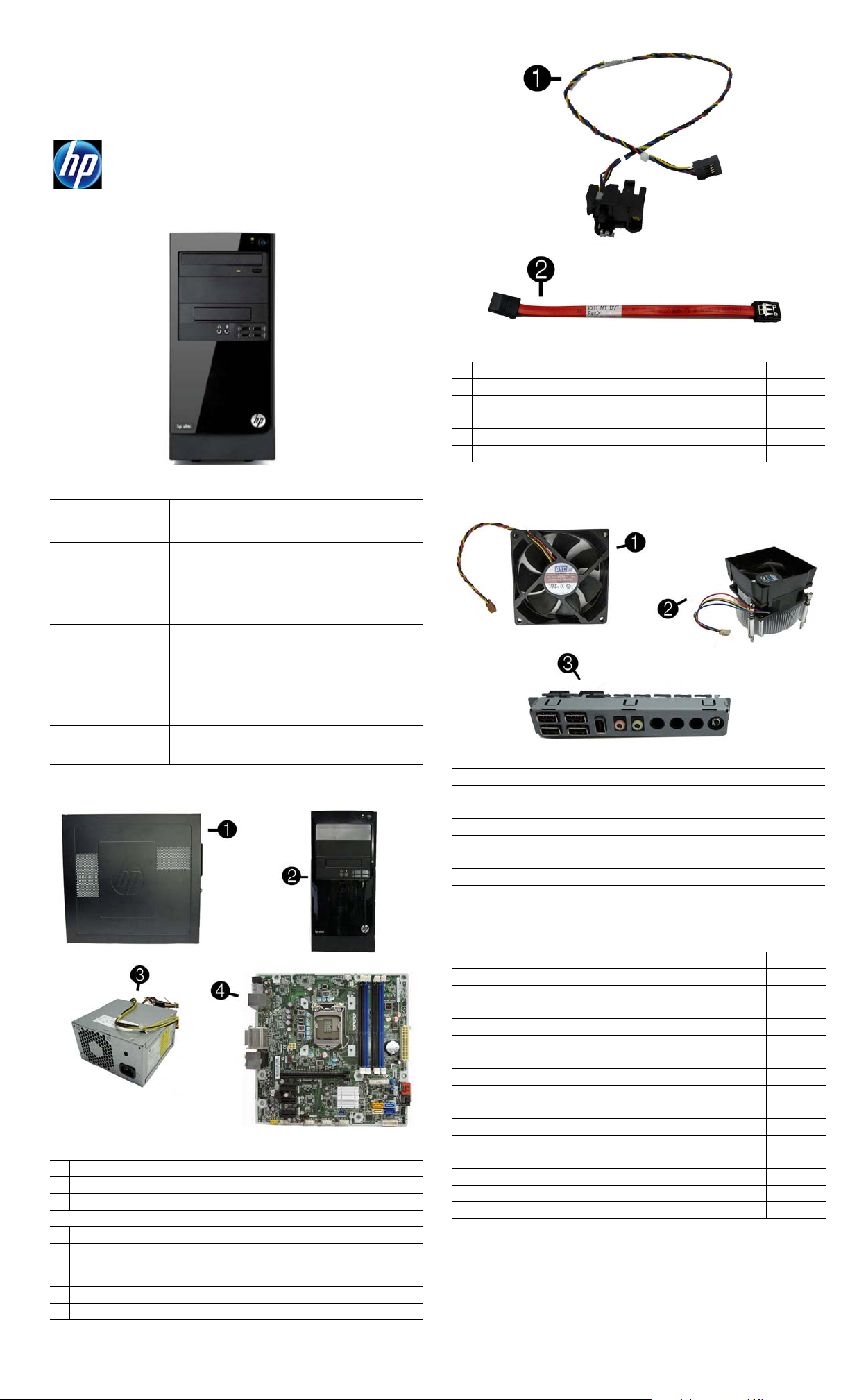
Cables
1 Power switch/LED assembly 657105-001
2 SATA cable, 165 mm 657102-001
* Adapter, DVI to VGA, HF 657401-001
* Adapter, DVI to VGA, 29-pin, HF 657851-001
* Antenna, for use with 2x2 WLAN modules 593890-001
* Antenna, for use with 1x1 WLAN modules 701397-001
*Not shown
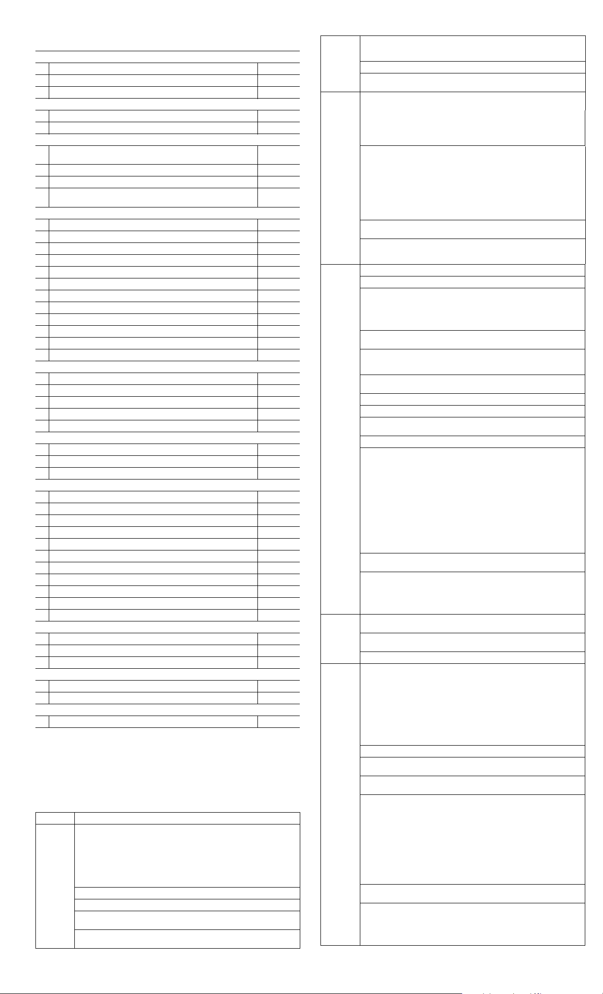
Miscellaneous Parts
1 Chassis fan 657103-001
2 Fan sink 657402-001
3 Front USB and I/O assembly 657113-001
* Card reader, bezel blank 657853-001
* Card reader, bezel 657854-001
* RTC battery 319603-001
* Rubber feet 530593-001
*Not shown
System Unit
1 Access panel 657104-001
2 Front bezel 657112-001
3 Power supply, 300W 656721-001
System boards with thermal grease, alcohol pad, and CPU socket cover
4 System board for use in 7300 models 656599-001
* System board for use in 7500 models 687940-001
* System board for use in 7500 models with Windows 8 with no Digital
Product Key (DPK)
* System board for use in 7500 models with Windows 8 Standard 696887-501
* System board for use in 7500 models with Windows 8 Professional 696887-601
* Not shown
696887-001
Mass Storage Devices (not illustrated)
16X SATA DVD±RW drive with 581600-001
Blu-ray BD-RW SuperMulti DL Drive 617030-001
Bezel, optical drive 657852-001
3 TB, 7200 rpm SATA hard drive 696961-001
3 TB, 5400 rpm SATA hard drive 668149-001
2 TB, 7200 rpm SATA hard drive 616608-001
2 TB, 5400 rpm SATA hard drive 613210-001
1.5 TB, 7200 rpm SATA hard drive, 6G 613209-001
1.5 TB, 5400 rpm SATA hard drive, 3G 652272-001
1 TB, 7200 rpm SATA hard drive 621418-001
750 GB, 7200 rpm SATA hard drive, 3G 632938-001
500 GB, 7200 rpm SATA hard drive, 3G 621421-001
320 GB, 7200 rpm SATA hard drive, 6G 621420-001
256 GB Solid-state drive (SSD) 661842-001
128 GB Solid-state drive (SSD) 665961-001
120 GB Solid-state drive (SSD) 661841-001
HP Elite 7300/7500, MT 663324-004 page 1
Page 2
Standard and Optional Boards (not illustrated)
Memory modules (PC3-10600, CL9) for use in 7300 models
*1 GB
*2 GB
*4 GB
Memory modules (PC3-12800, CL11) for use in 7500 models
*2 GB
*4 GB
WLAN modules
* Ralink RT5390R 802.11bgn 1x1 Wi-Fi Adapter for use in models with
Windows 8
* Ralink RT5390R 802.11bgn 1x1 Wi-Fi Adapter 701396-001
* Atheros AR9462 802.11b/g/n WiFi Adapter 701398-001
* Ralink RT3290LE 802.11bgn 1x1 Wi-Fi and Bluetooth 4.0 Combo
Adapter
Graphics adapters for use in models without Windows 8
*
ATI Radeon HD 7570 2-GB graphics adapter for use only on 7500 models
*
ATI Radeon HD 7450 1-GB graphics adapter for use only on 7500 models
* ATI Radeon HD 6570 2-GB graphics adapter, full height 638406-001
* ATI Radeon HD 6570 1-GB graphics adapter, full height 638405-001
* ATI Radeon HD 6450 1-GB graphics adapter 638132-001
* ATI Radeon HD 6450 512-MB graphics adapter 647449-001
*
nVidia GeForce GT640 3-GB graphics adapter for use only on 7500 models
*
nVidia GeForce GT630 2-GB graphics adapter for use only on 7500 models
*
nVidia GeForce GT620 1-GB graphics adapter for use only on 7500 models
* nVidia GeForce GT545 3-GB graphics adapter, full height 657107-001
* nVidia GeForce GT530 2-GB graphics adapter, full height 657106-001
* nVidia GeForce GT520 1-GB graphics adapter, full height 657399-001
Graphics adapters for use in models with Windows 8
*
ATI Radeon HD 7570 2-GB graphics adapter for use only on 7500 models
*
ATI Radeon HD 7450 1-GB graphics adapter for use only on 7500 models
*
nVidia GeForce GT640 3-GB graphics adapter for use only on 7500 models
*
nVidia GeForce GT630 2-GB graphics adapter for use only on 7500 models
*
nVidia GeForce GT620 1-GB graphics adapter for use only on 7500 models
Intel Core i7 processors (include thermal material)
* 3770K, 3.5 GHz, 8-MB L3 cache for use in only 7500 models 688165-001
* 3770,3.4 GHz, 8-MB L3 cache for use in only 7500 models 688164-001
* 2600S, 2.8 GHz, 8-MB L3 cache 638419-001
Intel Core i5 processors (include thermal material)
* 3570K, 3.4 GHz, 6-MB L3 cache for use in only 7500 models 688163-001
* 3570, 3.4 GHz, 6-MB L3 cache for use in only 7500 models 688162-001
* 3550, 3.3 GHz, 6-MB L3 cache for use in only 7500 models 687944-001
* 3470, 3.2 GHz, 6-MB L3 cache for use in only 7500 models 687943-001
* 3450, 3.1 GHz, 6-MB L3 cache for use in only 7500 models 687942-001
* 3330, 3.0 GHz, 6-MB L3 cache for use in only 7500 models 687941-001
* 2500S, 2.7 GHz, 6-MB L3 cache 638420-001
* 2500, 3.3 GHz, 6-MB L3 cache 638631-001
* 2400, 3.1 GHz, 6-MB L3 cache 638630-001
* 2310, 2.9 GHz, 6-MB L3 cache 657111-001
* 2300, 2.8 GHz, 6-MB L3 cache 654601-001
Intel Core i3 processors (include thermal material)
* 3240, 3.4 GHz, 3-MB L3 cache 688951-001
* 3220, 3.3 GHz, 3-MB L3 cache 688950-001
* 2125, 3.3 GHz, 3-MB L3 cache 677427-001
Intel Pentium Dual-Core processors (include thermal material)
* G870, 3.1 GHz, 3-MB L3 cache 691936-001
* G640, 2.8 GHz, 3-MB L3 cache 691935-001
Intel Celeron processor (include thermal material)
* G55, 3.3 GHz, 2-MB L3 cache 691934-001
635802-001
635803-001
585157-001
671612-001
671613-001
634906-001
701399-001
679219-001
679218-001
687226-001
687580-001
687579-001
701403-001
701402-001
701828-001
701405-001
701404-001
System Setup and Boot
Access the Setup Utility during computer boot by pressing the F10 key. If you do not
press F10 at the appropriate time, you must restart the computer and again press F10
when the monitor light turns green. NOTE: Not all settings are available for all models.
Computer Setup Menu
Heading Option/Description
File System Information - Lists the following main system specifications:
• Product name
• SKU number (some mo de l s )
• Processor type/speed/stepping
• Cache size (L1/L2/L3)
• Installed memory size/speed/ch
• Integrated MAC Address
About - Displays copyright notice.
Set Time and Date - Allows you to set system time and date.
Replicated Setup - Allows you to save or restore system configuration to/
from a USB flash drive.
Default Setup - Allows you to save current settings as default or restore
factory settings as default.
• System BIOS
• Chassis serial number
• Asset tracking number
• ME firmware version
• ME management mode
File
(continued)
Storage Device Configuration - Lists all installed BIOS-controlled storage
Security
Power OS Power Management - Allows you to enable/disable Runtime Power
Advanced Power-On Options - Allows you to set:
Apply Defaults and Exit - Applies the selected default setting s and clears
any established passwords.
Ignore Changes and Exit - Exits Computer setup without saving changes.
Save Changes and Exit - Saves changes to system configuration or
default settings and exits Computer Setup.
devices. The following options are available:
• CD-ROM
• Hard Disk
• Default Values
• Translation Mode
Storage Options - Allows you to set:
• eSATA Port - Set SATA port as eSATA port for use with external drive.
• SATA Emulation - Choose how the SATA controller and devices are
accessed by the OS. SATA Emulation choices are AHCI, RAID, or IDE.
• Removable Media Boot - Enables/disables ability to boot the system
from removable media.
• Max eSATA Speed - Allows you to choose 1.5 Gbps or 3.0 Gpbs as
the maximum eSATA speed. By default, the speed is limited to 1.5
Gbps for maximum reliability.
DPS Self-Test - Execute self-tests on ATA hard drives capable of performing the Drive Protection System (DPS) self-tests.
Boot Order - Specify boot order for UEFI and legacy boot sources. Also
specify hard drive boot order.
• Shortcut to Temporarily Override Boot Order
Setup Password - Set and enable the setup (Admin) password.
Power-On Password - Set and enable power-on password.
Password Options - Allows to you enable/disable:
• Lock Legacy Resources
• Setup Browse Mode
• Password prompt on F9 & F1 2
• Network Server Mode
Smart Cover - Allows you to lock/unlock the smart cover and set the
cover removal sensor to disable/notify user/setup password.
Device Security - Set Device Available/Device Hidden for: embedded security
device, system audio, network controller, USB controller, serial/parallel ports,
and SATA ports.
USB Security - Set Device Available/Device Hidden for front USB ports,
rear USB ports, internal USB ports, accessory USB ports.
Slot Security - Disable the PCI, PCIe, and Mini Card slots.
Network Boot - Enables/disables boot from OS (NIC models only).
System IDs - Allows you to update asset tag, ownership tag, UUID, key-
board locale setting.
Master Boot Record Security - enables/disables MBR.
System Security - Allows you to set:
• Data Execution Prevention (enable/disable)
• SVM CPU Virtualization (enable/disable).
• Virtualization Technology (VTx) (enable/disable)
• Virtualization Technology/Directed IO (VTd) (enable/disable)
• Trusted Execution Technology (enable/disable)
• Embedded Security Device (enable/disable)
• Reset to Factory Settings (Do not reset/Reset)
• Measure boot variables/devices to PCR1 (enable/di sable)
• OS management of Embedded Security Device (enable/disable)
• Reset of Embedded Security Device through OS (enable/disable)
• No PPI provisioning (Windows 8 only; enable/disable)
• Allow PPI policy to be changed by OS (enable/disable)
DriveLock Security - Allows you to assign or modify a master or user
password for hard drives.
Secure Boot Configuration (Windows 8 only)
• Legacy Support (enable/disable)
• Secure Boot (enable/disable).
• Key Management (enable/disable)
• Fast Boot (enable/disable)
Management, Idle Power Savings, Unique Sleep State Blink Rates.
Hardware Power Management - Enable/disable SATA power management,
S5 maximum power savings., PCI slots, network controller, USB 3.0 controller
Thermal - Control minimum fan speed.
• POST mode (QuickBoot, Clear Memory, FullBoot, or FullBoot Every x Days)
• POST messages (enable/disable)
• Press the ESC key for Startup Menu (enable/ disable)
• Option ROM Prompt (enable/disable)
• After Power Loss (off/on/previous state)
• POST Delay (none, 5, 10, 15, 20, or 60 seconds)
• Remote Wakeup Boot Source (remote server/local hard drive)
• Factory Recovery Boot Support (enable/disable)
• Bypass F1 Prompt on Configuration Changes (enable/disable)
BIOS Power-On - Set the computer to turn on at a preset time.
Bus Options - Allows you to enable/disable PCI SERR# Generation and
PCI VGA palette snooping.
Onboard Devices - Allows you to set resources for or disable on-board
system devices.
Device Options - Allows you to set:
• Printer mode (Bi-Directional, EPP + ECP, Output Only)
• Num Lock State at Power-on (off/on)
• Integrated Video (enable/disable)
• Integrated Graphics (Auto/Disable/Force)
• Internal Speaker (enable/disable)
• NIC PXE Option ROM Download (enable/disable)
• SATA RAID Option ROM Download (enable/disable)
• Multi-Processor (enable/disable)
• Hyper-threading (enable/disable)
• Turbo Mode (enable/disable)
VGA Configuration - Allows you to specify which VGA controller is the
“boot”/primary. Displayed only if add-in video card installed.
AMT Configuration - Allows you to set:
• AMT (enable/disable)
• Unconfigure AMT/ME (enable/disable)
• Hide Unconfigure ME Confirmation Prompt (enable/disable)
• Watchdog Timer (enable/disable)
• SSD Life Used
• SMART (ATA disks only)
• Diskette
•SATA Defaults
HP Elite 7300/7500, MT 663324-004 page 2
Page 3

Common POST Error Messages
Screen
Message Probable Cause Recommended Action
101-Option ROM
Error
103-System Board
Failure
163-Time & Date
Not Set
164-Memory Size
Error
164-Memory Size
Error
201-Memory Size
Error
214-DIMM Configuration Warning
219-ECC Memory
Module Detected
ECC Modules not
supported on this
Platform
301-, 304-Keyboard error
511-CPU Fan not
Detected
1805-Ambient
Temperature Previously Over Limit
2200-PMM Allocation Error during
MEBx Download
2201-MEBx Module did not checksum correctly
2202-PMM Deallocation Error during
MEBx cleanup
2230-General
error during MEBx
execution
2231-ME error during MEBx execution
2232-AMT error
during MEBx execution
System ROM or expansion
board option ROM checksum.
DMA or timers 1. Clear CMOS memory.
Invalid time or date in configuration memory.
RTC battery may need to be
replaced.
Memory amount has
changed since the last boot
(memory added/removed).
Incorrect memory configuration
RSM failure 1. Ensure memory modules are correctly
Populated DIMM configuration is not optimized
Recently added memory
module(s) support ECC
memory error correction.
Keyboard failure. 1. Reconnect keyboard with system turned off.
CPU Fan not Detected. 1. Reseat CPU fan.
This system was placed in a
low power state to prevent
damage due to excessive
environmental temperature.
(2200) Memory error during
POST execution of the Management Engine (ME) BIOS
Extensions option ROM.
(2201) Memory error during
POST execution of the Management Engine (ME) BIOS
Extensions option ROM.
(2202) Memory error during
POST execution of the Management Engine (ME) BIOS
Extensions option ROM.
(2230) Error occurred during
MEBx execution which fails
into the “General” grouping.
Status information displayed
along with the error provides
further clarity into the failure.
MEBx handles transference
of information between the
system BIOS and ME firmware.
(2231) Error occurred during
MEBx execution which fails
into “ME” grouping.
(2232) Error occurred during
MEBx execution which fails
into “AMT” grouping.
1. Verify ROM, reflash if required
2. Remove recently added cards to see if
problem remains.
3. Clear CMOS. If message disappears, may
be card problem.
4. Replace system board
2. Remove expansion boards.
3. Replace system board.
Reset the date and time under Control Panel
(Computer Setup can also be used). If the
problem persists, replace the R TC battery.
Press the F1 key to save the memory changes.
1. Run Setup (F10).
2. Make sure memory module(s) installed
properly.
3. If third-party memory added, test using HPonly memory.
1. Verify proper module type.
installed.
2. Verify proper module type.
3. Remove and replace faulty module(s).
4. If error persists after replacing mo dules,
replace system board.
Rearrange DIMMs so that each channel has
the same amount of memory.
1. If additional memory was recently added,
remove it to see if the problem remains.
2. Check product documentation for memory
support information.
2. Check kybd connection or keys.
3. Check connector for bent or missing pins.
4. Replace keyboard.
5. If 304, possible sys bd problem.
2. Reseat fan cable.
3. Replace CPU fan.
Make sure the system meets the HP enclosure
guidelines as listed in the Quick Specs, including the following:
1. Clean the air vents on the front, back, or any
other vented side of the computer.
2. Ensure that there is a 10.2 cm (4 in)
clearance on all vented sides of the
computer to permit the required airflow.
3. Ensure that computers are not so near each
other that they are subject to each other's
re-circulated or preheated air.
1. Reboot the computer.
2. Unplug the power cord, re-seat the memory
modules, and reboot the computer.
3. If the memory configuration was recently
changed, unplug the computer, restore the
original memory configuration, and reboot
the computer.
4. If the error persists, replace the system
board.
1. Reboot the computer.
2. If the error persists, update to the latest
BIOS version and ME firmware version.
3. If the error still persists, replace the system
board.
Diagnostic LEDs
LED Color LED Activity State/Message
Power Green On Computer on
Power Green 1 blink every 2 seconds Normal Suspend Mode
Power Red 1 blink every second followed
Power Red 3 blinks, 1 blink every second
Power Red 4 blinks, 1 blink every second
Power Red 5 blinks, 1 blink every second
Power Red 6 blinks, 1 blink every second
Power Red 7 blinks, 1 blink every second
Power Red 8 blinks, 1 blink every second
Power Red 9 blinks, 1 blink every second
Power Red 10 blinks, 1 blink every second
Power Red 11 blinks, 1 blink every second
none none System does not power on and
by a 2 second pause
followed by a 2 second pause
followed by a 2 second pause
followed by a 2 second pause
followed by a 2 second pause
followed by a 2 second pause
followed by a 2 second pause
followed by a 2 second pause
followed by a 2 second pause
followed by a 2 second pause
LEDs are not flashing
CPU thermal shutdown
Processor not installed
Power failure (power supply overload)
Pre-video memory error
Pre-video graphics error
System board failure (ROM
Invalid ROM based on Checksum
System powers on but is unable to boot
Bad option card
Current processor does not support a
feature previously enabled.
System unable to power on
Password Security
Establishing a Setup or Power-On password:
1. Turn on or restart the computer.
2. As soon as the computer turns on, press the Esc key while “Press the ESC key for Startup
Menu” message is displayed at the bottom of the screen.
3. Press the F10 key to enter Computer Setup.
4. To establish Setup password, select Security > Setup Password and follow the instructions.
- or To establish a Power-On password, select Security > Power-On Password and follow the
instructions on the screen
5. Before exiting, click File > Save Changes and Exit.
Changing a Setup or Power-On password:
1. Turn on or restart the computer.
To change the Setup password, go to step 2.
To change the Power-on password, go to step 3.
2. To change the Setup password, as soon as the computer turns on:
- Press the Esc key while “Press the ESC key for Startup Menu” message is displayed.
- Press the F10 key to enter Computer Setup.
3. When the key icon appears, type your current password, a slash (/) or alternate delimiter
character, your new password, another slash (/) or alternate delimiter character, and your new
password again as shown:
current password/new password/new password.
NOTE: Type the new password carefully since the characters do not appear on the screen.
4. Press Enter.
The new password will take effect the next time the computer is restarted.
Deleting a Power-On or Setup password
1. Turn on or restart the computer.
To delete the Setup password, go to step 2.
To delete the Power-On password, go to step 3.
2. To change the Setup password, as soon as the computer turns on:
- Press the Esc key while “Press the ESC key for Startup Menu” message is displayed.
- Press the F10 key to enter Computer Setup.
3. When the key icon appears, type your current password followed by a slash (/) or alternate
delimiter character as shown. Example: currentpassword/
4. Press Enter.
Clearing CMOS
1. Turn off the computer and disconnect the power cord from the power outlet.
2. Remove the access panel.
3. On the system board, locate the CMOS/password header.
4. Remove the jumper from pins 4 and 6.
5. Place the jumper on pins 4 and 2 for 10-15 seconds.
6. Replace the jumper on pins 4 and 6.
7. Replace the chassis access panel and reconnect the power cord.
8. Turn on the computer and allow it to start.
9. Use F10 setup to verify or configure new settings.
Clearing Passwords
1. Turn off the computer and disconnect the power cord from the power outlet.
2. Remove the access panel.
3. On the system board, locate the CMOS/password header.
4. Remove the jumper from pins 5 and 3.
5. Place the jumper on pins 3 and 1 for 10-15 seconds.
6. Replace the jumper on pins 5 and 3.
7. Replace the chassis access panel and reconnect the power cord.
8. Turn on the computer and allow it to start.
9. Use F10 setup to verify or configure new settings.
HP Elite 7300/7500, MT 663324-004 page 3
Page 4

System Board for use in HP Pro 7300 models System Board for use in HP Pro 7500 models
System Board Connectors and Jumpers (component location may vary)
CPU_FAN1 Heat sink fan connector
XMM1 Memory socket - channel A
XMM2 Memory socket - channel B
XMM3 Memory socket - channel A
XMM4 Memory socket - channel B F_AUDIO Front audio connector
ATXPOWER Main power connector PCIEX1_3 PCIe X1 slot
BATTERY RTC battery socket PCIEX1_2 PCIe X1 slot
MINI_CARD1 Mini PCIe connector SPDIF_OUT2 Internal SPDIF connector
CMOS/PSWD CMOS/password header PCIEX1_1 PCIe X1 slot
SATA4 SATA drive PCIEX16 PCIe X16 slot
SATA5 SATA drive AUDIO Audio connectors
SATA2 1st optical drive SYS_FAN1 Fan connector
HOOD_SENSOR
F_PANEL Front panel connector HDMI/DVI Combo HDMI/DVI connector
SATA0 1st hard drive LAN+USB LAN + USB connector
SATA1 2nd hard drive USB USB connectors
SATA3 2nd optical drive SPDIF_OUT21 External SPDIF connector
Hood sensor connector ATX_CPU CPU power connector
F_USB1
F_USB2
F_USB3
F_USB4
1st USB connector
2nd USB connector
3rd USB connector
4th USB connector
System Board Connectors and Jumpers (component location may vary)
SPDIF_OUT1 Internal SPDIF connector SATA2 1st optical drive
PUMP_FAN CPU cooler connector SATA3 2nd optical drive
ATX_CPU CPU power connector
CPU_FAN1 Heat sink fan connector
XMM1 Memory socket - channel A BATTERY RTC battery socket
XMM2 Memory socket - channel B
XMM3 Memory socket - channel A F_AUDIO Front audio connector
XMM4 Memory socket - channel B PCIEX1_3 PCIe X1 slot
ATXPOWER Main power connector PCIEX1_2 PCIe X1 slot
MINI_CARD1 Mini PCIe connector PCIEX1_1 PCIe X1 slot
CMOS/PW CMOS/password header PCIEX16 PCIe X16 slot
SATA4 SATA drive AUDIO Audio connectors
SATA5 SATA drive SYS_FAN1 Fan connector
HOOD_SENSE
F_PANEL Front panel connector SS_USB1 USB 3.0 connectors
F_SSUSB1 Internal USB 3.0 connector LAN+USB LAN + USB connector
SATA0 1st hard drive USB1 USB 2.0 connectors
SATA1 2nd hard drive
Hood sensor connector DVI-D//DVI-I Combo HDMI/DVI connector
F_USB1
F_USB2
F_USB3
1st USB connector
2nd USB connector
3rd USB connector
HP Elite 7300/7500, MT 663324-004 page 4
 Loading...