

Page 1
Illustrated Parts & Service Map
HP Elite 7100 Series Microtower PC
© 2010 Hewlett-Packard Development Company, L.P. The information con-
tained herein is subject to change without notice. HP shall not be liable for
technical or editorial errors or omissions contained herein.
Document Number 606037-001. 1st Edition February 2010.
Mass Storage Devices (not illustrated)
22-in-1 media card reader, 3.5-inch 480032-001
16X SATA DVD±RW and CD-RW drive with LightScribe 581600-001
16X SATA DVD-ROM drive 581599-001
Blu-ray ROM DVD±R/RW SuperMulti DL Drive with LightScribe 581601-001
1 TB (1000 GB) SATA hard drive 585465-001
500 GB SATA hard drive 586720-001
320 GB SATA hard drive 586969-001
250 GB, 7200-RPM SATA hard drive 586719-001
160 GB, 7200-RPM SATA hard drive 586718-001
64 GB solid state drive (SSD) 581057-001
250-GB hard drive, USB 586383-001
500019-001
Key Specifications
Processor Type Intel® Core™ i3, Intel Core i5, Intel Core i7
Maximum RAM 16 GB; PC-3-10600 (1333MHz) DDR3 SDRAM
Expansion Slots • 1 PCI x16
Integrated Graphics Integrated Intel HD graphics
Chipset Intel H57 Express
Drive Support • External: (2) 5.25-inch and (1) 3.5-inch drive bays
I/O Interfaces Front: (3) USB ports, 1394, microphone, headphone
Operating Systems • Windows® 7
• 3 PCI x1
• Internal: (2) 3.5-inch drive bays
Rear: (6) USB ports, (1) RJ-45, (1) 1394, (1) audio in, (1)
audio out, (1) microphone, (1) surround center, (1) surround
right, (1) surround left, (1) optical out, (1) VGA, (1) DVI
• Windows XP Professional (downgrade from Windows 7)
• Windows Vista® Business
• Novell SUSE Linux Enterprise Desktop 11
• FreeDOS
Spare Parts
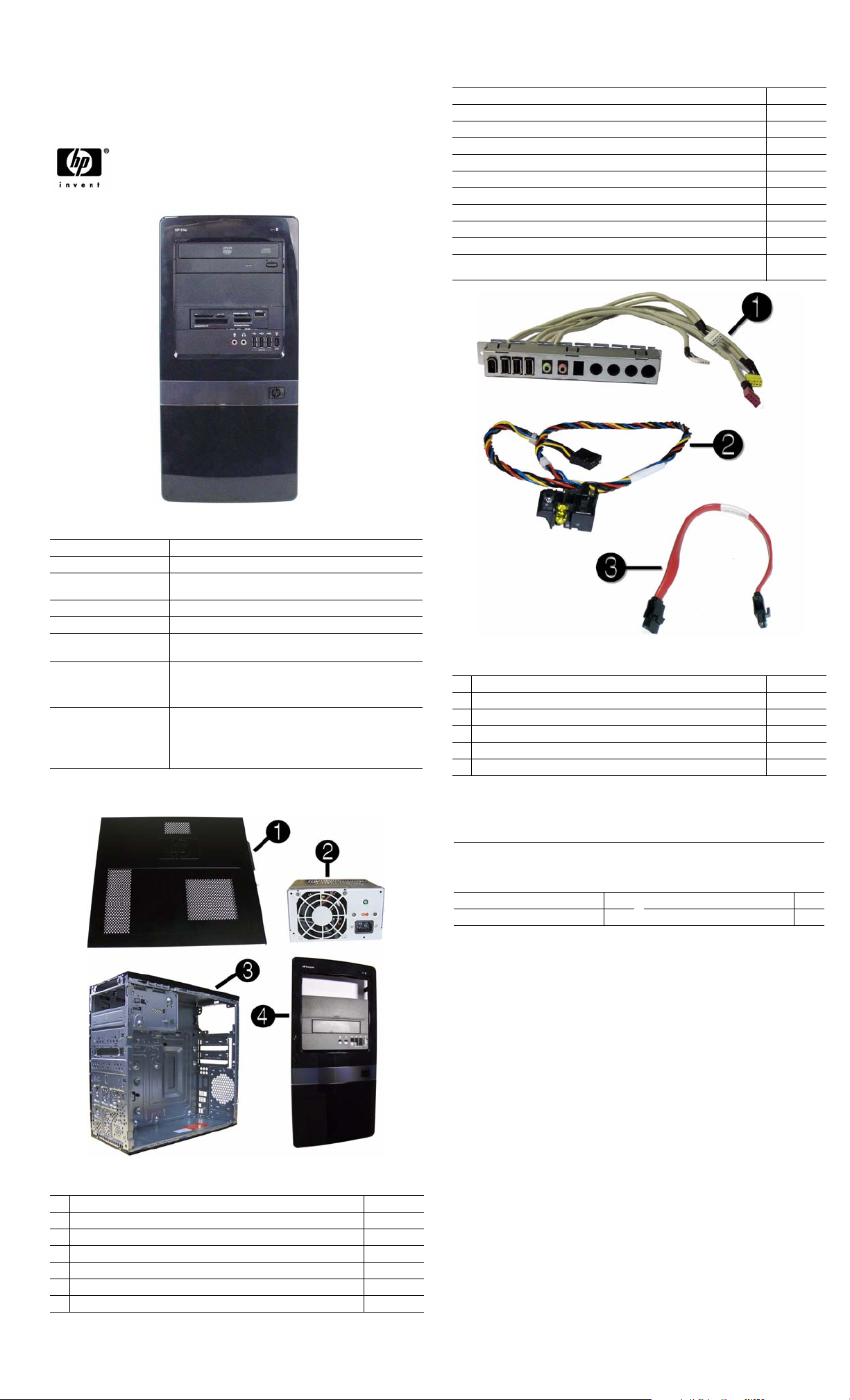
Cables
1 Front I/O with USB 487744-001
2 Power switch/LED cable assembly 464574-001
3 SATA HDD cable, 4 inch (10 cm) 449283-001
* SATA cable, 6.5 inch (16.5 cm) 448670-001
* DMS-59 to dual VGA 463023-001
* DMS-59 to dual DVI 463024-001
*Not shown
Keyboards (not illustrated)
USB, Standard
USB, Smart card*
USB, Washable
USB, Mini
Brazil* -201 Latin America* -161
French Canada -121
*537747-xxx only
537746-xxx
537747-xxx
577495-xxx
535873-xxx
U.S. -001
System Unit
1 Access panel 586372-001
2 Power supply, 300W, PFC 604611-001
2 Power supply, 300W, 85% efficient 575437-002
3 Chassis not spared
4 Front bezel 586373-001
* 5.25-inch bezel blank 536306-001
* 3.5-inch bezel blank 583094-001
* Not shown
HP Elite 7100 MT Series 606037-001 page 1
Page 2
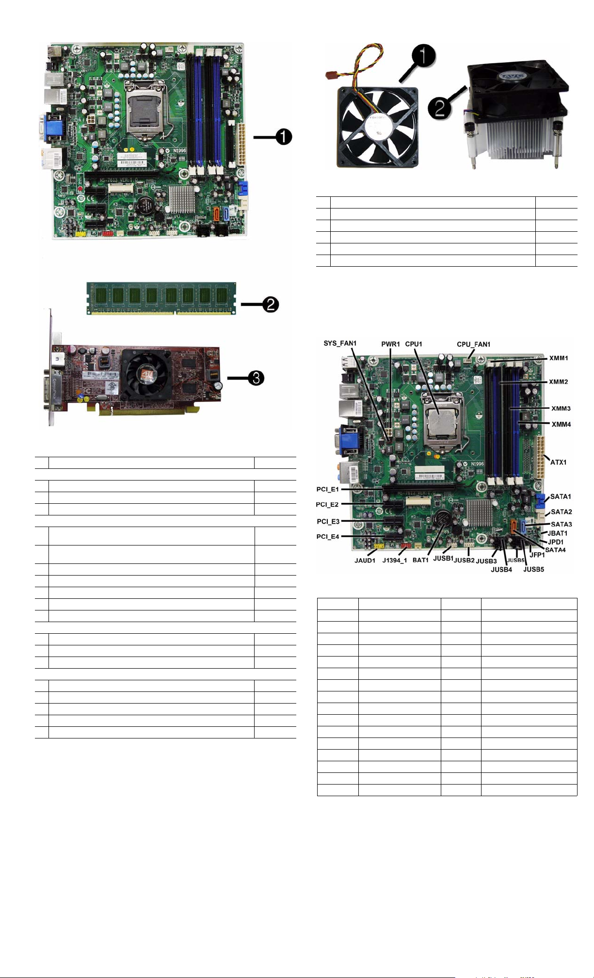
Standard and Optional Boards
1 System board, includes heat sink backplate 601312-001
Memory modules (DDR3, PC3-10600)**
*4 GB
*2 GB
21 GB
Other boards
3 ATI Radeon HD 4550 256-MB Dual Head graphics adapter (PCIe x16),
includes bracket
* ATI Radeon HD 4650 1-GB Dual Head graphics adapter (PCIe x16),
includes bracket
* nVidia GeForce GT230 1.5-GB graphics adapter, includes bracket 586381-001
* nVidia GeForce G210 512-MB graphics adapter, includes bracket 586382-001
* Intel Pro 1000 PT Gb Ethernet PCIe NIC, includes bracket 490367-001
* LSI PCIe x1 56K International SoftModem, includes bracket 490689-001
* 802.11b/g/n WLAN PCIe adapter 538048-001
Intel Core processors (8-MB L3 cache, 1333-MHz FSB, quad core)
* i7-870, 2.93-GHz processor 586378-001
* i7-860, 2.80-GHz processor 586377-001
* i5-750, 2.66-GHz processor 586376-001
Intel Core processors (4-MB L3 cache, 1333-MHz FSB, dual core)
* i5-670, 3.46-GHz processor 604616-001
* i5-660, 3.33-GHz processor 604615-001
* i5-650, 3.2-GHz processor 604614-001
* i3-540, 3.06-GHz processor 604613-001
* i3-530, 2.93-GHz processor 604612-001
* Not shown
585157-001
576110-001
576109-001
538051-001
584217-001
578174-001
Miscellaneous Parts
1 Chassis fan 449207-001
2 Heat sink with alcohol pad and factory-applied thermal grease 586374-001
* Rubber feet 530593-001
* Mouse, optical, black 537749-001
* Mouse, USB laser 570580-001
* USB-powered speakers 466618-001
*Not shown
LP = Low profile
System Board
System Board Connectors and Jumpers (position of some untitled
components may vary in location)
CPU1 Processor JUSB1 Front USB
CPU_FAN1 Primary CPU fan BAT Real-time-clock battery
DIMM4 DIMM 4 (Channel A) CON1 Internal connector
DIMM3 DIMM 3 (Channel B) J1394_1 Front 1394 port connector
DIMM2 DIMM 2 (Channel A) JAUD1 Front audio connector
DIMM1 DIMM 1 (Channel B) PCI_E4 PCIe X1, slot 3
ATX1 Main power PCI_E3 PCIe X1, slot 2
SATA1 Primary HDD connector PCI_E2 PCIe X1, slot 1
SATA2 Primary ODD connector PCI_E1 PCIe X16 slot
SATA3 Secondary HDD connector AUDIO1 External audio connector
SATA4 Secondary ODD connector SYS_FAN1 Primary chassis fan
JFP1 Power button/LED
JUSB6 USB connector PWR1 CPU power
JUSB5 USB connector LAN_USB1 RJ-45/USB connector
JUSB4 USB connector
JUSB3 Front I/O connector SPDIF SP/DIF connector
JUSB2
Media card reader connector
JVGA_DVI1
I1394_USB1
USB1 USB connector
Display/DVI connector
1394 port/USB connector
HP Elite 7100 MT Series 606037-001 page 2
Page 3

Setup Utility
Basic system information is in the Setup Utility held in the system ROM, accessed by pressing
F10 when prompted (on screen) during the boot sequence.
Computer Setup Menu
Heading Option / Description
Main System Time Allows you to set system time.
System Date Allows you to set system date.
Language Allows you to select the language.
1st Drive
2nd Drive
3rd Drive
4th Drive
System Information Allows you to view installed memory, memory banks 1-
Model Number Allows you to modify the model number.
Serial Number Allows you to manually enter the serial number.
Asset Tag Allows you to manually enter the Asset Tag.
Product Number View only. Allows you to view the product number.
Advanced CPU Type View only.
CPU Speed View only.
Cache RAM(L2) View only.
Cache RAM(L3) View only.
Primary Video
Adapter
SATA Controller
Mode
SATA Controller Allows you to disable/enable the SATA controller.
Onboard LAN Disable/enable onboard LAN controller.
Onboard LAN Boot
ROM
USB Ports Allows you to individually enable/disable available USB
Onboard 1394 Allows you to enable/disable all 1394 ports.
Supervisor Password Allows you to view the supervisor password.
User Password Allows you to view the user password.
Onboard Audio Auto/disable/enable.
ESC: Boot Menu Allows you to enable/disable the option to press the Esc
F9:Diagnostics Allows you to enable/disable the option to press the F9
F10:Setup Allows you to enable/disable the option to press the F10
F11:Recovery Allows you to enable/disable the option to press the F11
F12:Boot from LAN Allows you to enable/disable the option to press the F12
Power After AC Power Fail-
Boot Boot-time Diagnostic
Exit Exit Saving Changes Press Enter to exit saving changes.
ure
Hyper-threading Disable/enable.
XD (Execute Disable) Disable/enable XD bit.
Virtualization Technology
WOL from S5 Allows you to enable/disable Limited (normal shut-
Screen
Boot Device Priority:
1st Boot Device, 2nd
Boot Device, 3rd
Boot Device, 4th Boot
Device
Floppy Group Boot
Priority
CD-ROM Boot Priority
Hard Drive Boot Priority
Network Group Boot
Priority
Exit Discarding
Changes
Load Setup Defaults Press Enter to load setup defaults.
Discard Changes Press Enter to discard changes.
Save Changes Press Enter to save changes.
Allow you to: view capacity (HDD only). Also allows
you to run HDD self-test for selected channel: SMART
status check, SMART short self test, SMART extended
self test.
4, BIOS revision, core version.
Allows you to select boot display device when more
than 2 video options are offered by system: PCIe x1 and
PCIe x16.
If SATA controller is enabled, allows you to set the
mode to: IDE, AHCI, RAID.
Disable/enable the boot ROM of the onboard LAN chip.
ports.
key to access the Boot menu during computer startup.
key to access the Diagnostics menu during computer
startup.
key to access the Setup menu during computer startup.
key to access the Recovery menu during computer startup.
key to access the Boot from LAN option
during computer startup.
Allows you to select system restart behavior after power
loss: Stay off, Power on, Auto.
Disable/enable.
down) WOL from S5 support.
Disable/enable POST diagnostic messages display.
Allows you to specify which device groups will boot
first, second, third, and fourth or to disable any
of the four: Floppy group, CD-ROM group, Hard drive
group, Network boot group. MS-DOS drive lettering
assignments maybe apply after a non-MS-DOS operating system has started.
Specifies boot device priority within removable devices.
Specifies boot device priority within CD/DVD drives.
Specifies boot device priority within hard drives.
Specifies boot device priority within bootable network
devices.
Press Enter to exit discarding changes.
Recovering the Configuration Settings
To reset all BIOS Setup options to their default values (including options for Ctrl+F10), you
must enter F10 Setup mode and press F5.
This does not include updates to system date, system time, supervisor password, user password,
and CPU frequency multiplier.
Password Security
This computer supports security password features, which can be established through the
Computer Setup Utilities menu.
This computer supports two security password features that are established through the
Computer Setup Utilities menu: setup password and power-on password. When you establish
only a setup password, any user can access all the information on the computer except Computer
Setup. When you establish only a power-on password, the power-on password is required to
access Computer Setup and any other information on the computer. When you establish both
passwords, only the setup password will give you access to Computer Setup.
When both passwords are set, the setup password can also be used in place of the power-on
password as an override to log in to the computer. This is a useful feature for a network
administrator.
If you forget the password for the computer, you can clear that password so you can gain access
to the information on the computer by resetting the password jumper.
Resetting the password jumper
1. Shut down the computer. With the power cord disconnected, press the power button again to
drain the system of any residual power.
2. Remove the access panel.
3. Locate the header and jumper labeled JPD1.
4. Remove the jumper from pins 1 and 2. Place the jumper on pins 2 and 3.
5. Replace the access panel.
6. Plug in and turn on power. Allow the operating system to start. This clears the current
passwords and disables the password features.
7. To establish new passwords, repeat steps 1 - 4, replace the password jumper on pins 1 and 2,
then repeat steps 5 - 6. Establish new passwords in Computer Setup.
Resetting the CMOS jumper
The CMOS button resets CMOS but does not clear the power-on and setup passwords.
1. Turn off the computer and any external devices, and disconnect power.
2. Remove the access panel.
3. Locate the header and jumper labeled JBAT1.
4. Remove the CMOS jumper from pins 1 and 2 and put the jumper on pins 2 and 3. This clears
the CMOS.
5. Put the jumper back on pins 1 and 2.
6. Replace the access panel, external devices, and reconnect the power cord.
7. Turn on the computer.
Use Computer Setup to reset any special system setups along with the date and time.
HP Vision Diagnostics
The Hewlett-Packard Vision Diagnostics utility allows you to view information about the hardware configuration of the computer and perform hardware diagnostic tests on the subsystems of
the computer. The utility simplifies the process of effectively identifying, diagnosing, and isolating hardware issues.
The Survey tab is displayed when you invoke HP Vision Diagnostics. This tab shows the current
configuration of the computer. From the Survey tab, there is access to several categories of
information about the computer. Other tabs provide additional information, including diagnostic
test options and test results. The information in each screen of the utility can be saved as an html
file and stored on a USB flash drive.
Use HP Vision Diagnostics to determine if all the devices installed on the computer are recognized by the system and functioning properly. Running tests is optional but recommended after
installing or connecting a new device.
Vision Diagnostics may be found on the CD that shipped with some computer models. The tool
may also be downloaded from the HP Web site using the following procedure:
1. Go to www.hp.com
2. Click the Software & Drivers link.
3. Select Download drivers and software (and firmware).
4. Enter the product number in the text box and press Enter.
5. Select the specific product.
6. Select the OS.
7. Click the Diagnostic link.
8. Click Hewlett-Packard Vision Diagnostics.
9. Click Download.
NOTE: The download includes instructions on how to create a bootable CD or USB flash drive.
POST Front Panel LEDs and Audible Codes
Beeps/
Activity Meaning Recommended Action
1 short, 1 long,
3 sec pause
2 short, 1 long,
3 sec pause
3 short, 1 long,
3 sec pause
1 short,
1 sec pause
2 short,
1 sec pause
3 short,
1 sec pause
4 short,
1 sec pause
5 short,
1 sec pause
Bad memory or memory
configuration error.
No graphics card installed
or graphics card initialization failed.
CPU configuration error or
invalid CPU detected
before graphics card initialized.
No optical drive found. 1. Check cable connections.
No CD found. 1. Check the type of drive and use the correct
Flashing not ready (missing utility or BIOS image
file, etc.)
Flashing operation has
failed (checksum
error, corrupted image,
etc.)
BIOS recovery was successful.
Check that the memory modules have been
installed correctly and that proper modules are
used.
For systems with a graphics card:
1. Reseat graphics card. Power on system.
2. Replace the graphics card.
3. Replace the system board.
For systems with integrated graphics, replace
the system board.
1. Upgrade the BIOS to proper version.
2. Change the processor.
2. Run the Computer Setup utility and ensure
the device port is enabled.
media type.
2. Replace the CD with a new one.
Upgrade the BIOS to proper version.
1. Verify the correct ROM.
2. Flash the ROM if needed.
3. If an expansion board recently added,
remove to see if the problem remains.
4. Clear CMOS.
5. If the message disappears, there may be a
problem with the expansion card.
6. Replace the system board.
No action required.
HP Elite 7100 MT Series 606037-001 page 3
 Loading...