

Page 1

HP Pavilion dm4 Entertainment PC
Maintenance and Service Guide
Page 2

© Copyright 2011 Hewlett-Packard
Development Company, L.P.
Bluetooth is a trademark owned by its
proprietor and used by Hewlett-Packard
Company under license. Intel, Core, and
Centrino are trademarks of Intel
Corporation in the U.S. and other countries.
Microsoft and Windows are U.S. registered
trademarks of Microsoft Corporation. SD
Logo is a trademark of its proprietor.
The information contained herein is subject
to change without notice. The only
warranties for HP products and services are
set forth in the express warranty statements
accompanying such products and services.
Nothing herein should be construed as
constituting an additional warranty. HP shall
not be liable for technical or editorial errors
or omissions contained herein.
Third Edition: December 2011
First Edition: May 2011
Document Part Number: 639435-003
Page 3

Safety warning notice
WARNING! To reduce the possibility of heat-related injuries or of overheating the computer, do not
place the computer directly on your lap or obstruct the computer air vents. Use the computer only on
a hard, flat surface. Do not allow another hard surface, such as an adjoining optional printer, or a soft
surface, such as pillows or rugs or clothing, to block airflow. Also, do not allow the AC adapter to
contact the skin or a soft surface, such as pillows or rugs or clothing, during operation. The computer
and the AC adapter comply with the user-accessible surface temperature limits defined by the
International Standard for Safety of Information Technology Equipment (IEC 60950).
iii
Page 4

iv Safety warning notice
Page 5

Table of contents
1 Product description ........................................................................................................................................ 1
2 External component identification ................................................................................................................ 5
Top ....................................................................................................................................................... 5
TouchPad ............................................................................................................................ 5
Lights ................................................................................................................................... 6
Buttons ................................................................................................................................. 7
Keys ..................................................................................................................................... 8
Front ..................................................................................................................................................... 9
Right side ............................................................................................................................................. 9
Left side .............................................................................................................................................. 10
Display ................................................................................................................................................ 11
Rear .................................................................................................................................................... 12
Bottom ................................................................................................................................................ 12
3 Illustrated parts catalog ............................................................................................................................... 13
Serial number location ........................................................................................................................ 13
Computer major components ............................................................................................................. 14
Display assembly components ........................................................................................................... 19
Plastics Kit .......................................................................................................................................... 20
Mass storage devices ......................................................................................................................... 21
Miscellaneous parts ............................................................................................................................ 22
Sequential part number listing ............................................................................................................ 23
4 Removal and replacement procedures ....................................................................................................... 29
Preliminary replacement requirements ............................................................................................... 29
Tools required .................................................................................................................... 29
Service considerations ....................................................................................................... 29
Plastic parts ....................................................................................................... 29
Cables and connectors ..................................................................................... 30
Drive handling ................................................................................................... 30
v
Page 6

Grounding guidelines ......................................................................................................... 31
Electrostatic discharge damage ........................................................................ 31
Packaging and transporting guidelines ............................................. 32
Workstation guidelines ..................................................................... 32
Equipment guidelines ....................................................................... 33
Component replacement procedures ................................................................................................. 34
Serial number .................................................................................................................... 34
Computer feet .................................................................................................................... 35
Battery ............................................................................................................................... 36
Memory module ................................................................................................................. 37
RTC battery ....................................................................................................................... 39
WLAN module .................................................................................................................... 40
Hard drive .......................................................................................................................... 43
Optical drive ....................................................................................................................... 45
Keyboard ........................................................................................................................... 47
Top cover ........................................................................................................................... 49
Fingerprint reader board .................................................................................................... 53
Power button board ........................................................................................................... 55
Display assembly ............................................................................................................... 56
USB board ......................................................................................................................... 63
Power connector cable ...................................................................................................... 64
Bluetooth module ............................................................................................................... 66
Speaker assembly ............................................................................................................. 68
System board ..................................................................................................................... 70
Fan/heat sink assembly ..................................................................................................... 72
Processor ........................................................................................................................... 77
5 Setup Utility ................................................................................................................................................... 79
Starting Setup Utility ........................................................................................................................... 79
Using Setup Utility .............................................................................................................................. 79
Changing the language of Setup Utility ............................................................................. 79
Navigating and selecting in Setup Utility ............................................................................ 80
Displaying system information ........................................................................................... 80
Restoring default settings in Setup Utility .......................................................................... 80
Exiting Setup Utility ............................................................................................................ 81
Setup Utility menus ............................................................................................................................ 82
Main menu ......................................................................................................................... 82
Security menu .................................................................................................................... 82
System Configuration menu .............................................................................................. 82
Diagnostics menu .............................................................................................................. 83
vi
Page 7

6 Specifications ................................................................................................................................................ 84
Computer specifications ..................................................................................................................... 84
35.56 cm (14.0 in) display specifications ............................................................................................ 85
Hard drive specifications .................................................................................................................... 86
DVD±RW SuperMulti Double-Layer Drive specifications ................................................................... 87
System resource specifications .......................................................................................................... 88
7 Backup and recovery .................................................................................................................................... 89
Restore ............................................................................................................................................... 90
Creating restore media ....................................................................................................................... 90
Performing a system restore .............................................................................................................. 91
Restoring using the dedicated recovery partition (select models only) .............................. 91
Restoring using the restore media ..................................................................................... 92
Changing the computer boot order .................................................................................... 92
Backing up and recovering your information ...................................................................................... 93
Using Windows Backup and Restore ................................................................................ 94
Using Windows system restore points ............................................................................... 95
When to create restore points ........................................................................... 95
Create a system restore point ........................................................................... 95
Restore to a previous date and time ................................................................. 95
8 Recycling ....................................................................................................................................................... 96
Battery ................................................................................................................................................ 96
Display ................................................................................................................................................ 96
Index ................................................................................................................................................................. 102
vii
Page 8

viii
Page 9

1 Product description
Category Description Discrete UMA
Product Name HP Pavilion dm4 Entertainment PC √√
Processors Intel® Core™ i7 processor
i7-2620M Dual-Core processor (2.7 GHz, SC turbo
up to 3.40 GHz), 4 MB L3 cache, 35 W
Intel Core i5 processors
i5-2540M Dual-Core processor (2.6 GHz, SC turbo
up to 3.3 GHz), 3 MB L3 cache, 35 W
i5-2520M Dual-Core processor (2.5 GHz, SC turbo
up to 3.2 GHz), 3 MB L3 cache, 35 W
i5-2430M Dual-Core processor (2.4 GHz, SC turbo
up to 3.0 GHz), 3 MB L3 cache, 35 W
i5-2410M processor (2.3 GHz, turbo up to 2.9 GHz),
3 MB L3 cache, 35 W
Intel Core i3 processors
i3-2330M Dual-Core processor (2.2 GHz), 3 MB L3
cache, 35 W (soldered to system board)
i3-2310M Dual-Core processor (2.1 GHz), 3 MB L3
cache, 35 W (soldered to system board)
Chipset Intel HM65 Express √√
Graphics Switchable discrete graphics (HD Decode, DX11,
and HDMI)
ATI Radeon™ HD 6470M) with 1024MB of
dedicated video memory (128M x16 DDR3, 900
MHz x 4 PCs)
√√
√√
√√
√√
√√
√
√
√
Internal Intel HD Graphics
HD Graphics 3000 (Intel HM65)
Panel 35.56 cm (14.0 in) HD LED BrightView (1366 x 768
resolution)
16:9 ultra wide aspect ratio √√
Typical brightness: 200 nits √√
Memory 2 SODIMM slots √√
√
√√
1
Page 10

Customer-accessible and upgradable √√
Supports up to 8 GB of system memory √√
DDR3-1333MHz dual channel support √√
Supports the following configurations: √√
● 3072 MB (1024 MB x 1 + 2048 MB x 1)
● 1024 MB (1024 MB x 1) (No support for
Hard drives HP ProtectSmart Hard Drive Protection √√
Supports the following 9.5 mm, 6.35 cm (2.5 in)
● 500 GB, 7200 rpm
8192 MB (4096 MB x 2) (No support for 32 bit
●
operating systems)
6144 MB (2048 MB x 1 + 4096 MB x 1) (No
●
support for 32 bit operating systems)
4096 MB (2048 MB x 2)
●
4096 MB (4096 MB x 1)
●
2048 MB (2048 MB x 1)
●
2048 MB (1024 MB x 2)
●
Microsoft Windows 7, 64 bit)
SATA hard drives
750 GB, 7200 rpm
●
640 GB, 7200 rpm
●
320 GB, 7200 rpm
●
√√
Supports the following solid-state drive: √√
● 160 GB √√
Optical drives Supports the DVD±R/RW SuperMulti Double-Layer
Drive (9.5 mm tray load, fixed, SATA) (select
models only)
Optical drive weight saver available for non-ODD
models
Camera HP TrueVision HD √√
Fixed (no tilt), activity LED √√
1280 × 800 by 30 frames per second √√
Microphone One microphone, digital (software included) √√
Echo cancellation and noise suppression √√
Audio Dolby Home Theater, HD audio √√
Supports Microsoft Premium requirements √√
Altec Lansing speakers (2) √√
Ethernet Integrated 10/100/1000 network interface card (NIC) √√
√√
2 Chapter 1 Product description
Page 11

Wireless Integrated wireless local area network (WLAN)
options by way of wireless module:
√√
Intel Centrino Wireless-N 1000 802.11b/g/n 1x2 with
WiDi support
Intel Centrino advanced wireless-N 1030 +
Bluetooth® combo 802.11b/g/n 1x2 with WiDi
support
Intel Centrino Advanced–N + WiMAX 6150, 802.11
b/g/n with WiDi support
Intel Centrino Advanced–N + WiMAX 6150 +
Bluetooth 802.11 b/g/n with WiDi support
Realtek RTL8191SE 802.11b/g/n 1x1 WiFi Adapter √√
Ralink 5390GN 802.11b/g/n 1x1 WiFi Adapter √√
Atheros AR9002WB-1NGB 802.11b/g/n 1x1 WiFi
and Bluetooth 2.1+EDR Combo Adapter (BT3.0+HS
ready)
Realtek RTL8188CE 802.11b/g/n WiFi with Realtek
CSRBC4 Bluetooth 2.1+EDR Adapter
Atheros 9485GN 802.11b/g/n 1x1 WiFi and 3012
Bluetooth 4.0 Combo Adapter
Broadcom 4313GN 802.11b/g/n 1x1 WiFi and
20702 Bluetooth 4.0 Combo Adapter
External media card Digital Media Slot; supports SD/SDHC/SDXC, MMC √√
√√
√√
√√
√√
√√
√√
√√
√√
Internal media card
expansion
Ports VGA (Dsub 15-pin) supporting:
Hot plug/unplug and auto detect for wide-aspect or
HDMI v1.4 supporting up to 1080p, 1920 x 1200 @
USB 2.0 (4) √√
RJ-45 √√
Audio in (microphone) √√
Audio-out (headphone) √√
Smart-pin AC adapter plug √√
Keyboard/pointing devices 35.56 cm (14.0 inch) full-size keyboard √√
Dura-coat island style keyboard √√
TouchPad with tab cover (taps and multitouch
One half-size mini-card slot for WLAN √√
√√
2048 x 1536 resolution at 75 Hz
√√
standard-aspect video
√√
60 Hz DVI mode
√√
gestures (2-finger scrolling, taps, and pinch zoom
enabled by default)
Power requirements Batteries
3
Page 12

Supports battery fast charge √
9-cell (100 Whr) 3.0 Ah Li-ion battery √√
6-cell (62-Whr) 2.80Ah Li-ion battery √√
6-cell (55-Whr) 2.55 Ah Li-ion battery √√
AC Adapters
65 W AC adapter with Smart-Pin DC connector √
90 W AC adapter with Smart-Pin DC connector √
Security Kensington Security Lock √√
Fingerprint reader with Digital Persona Software
Support
OTP (VeriSign) support √√
Intel AT-p ready support √√
Operating system Preinstalled:
Microsoft Windows 7 Professional (32 and 64 bit) √√
Microsoft Windows 7 Home Premium (32 and 64
bit)
Microsoft Windows 7 Home Basic (32 and 64 bit) √√
Microsoft Windows 7 Starter (32 bit), (No support for
HDD 320 GB)
FreeDOS √√
RedFlag √√
Serviceability End-user replaceable parts: √√
AC adapter √√
Battery (system) √√
Hard drive √√
Memory module √√
√√
√√
√√
Optical drive √√
Mini-card device √√
4 Chapter 1 Product description
Page 13
2 External component identification
Top
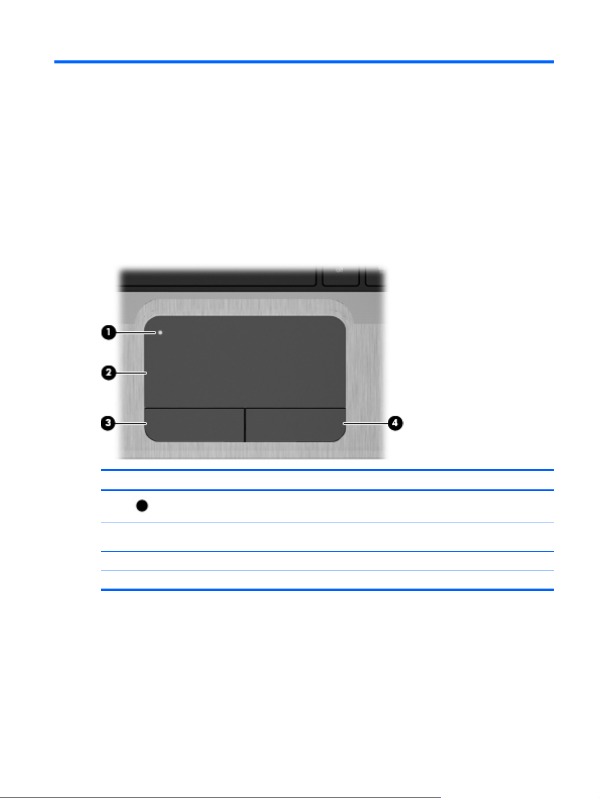
TouchPad
Component Description
(1)
(2) TouchPad zone Moves the pointer and selects or activates items on the
(3) Left TouchPad button Functions like the left button on an external mouse.
(4) Right TouchPad button Functions like the right button on an external mouse.
TouchPad light Turns the TouchPad on and off. Quickly double-tap the
TouchPad light to turn the TouchPad on and off.
screen.
Top 5
Page 14
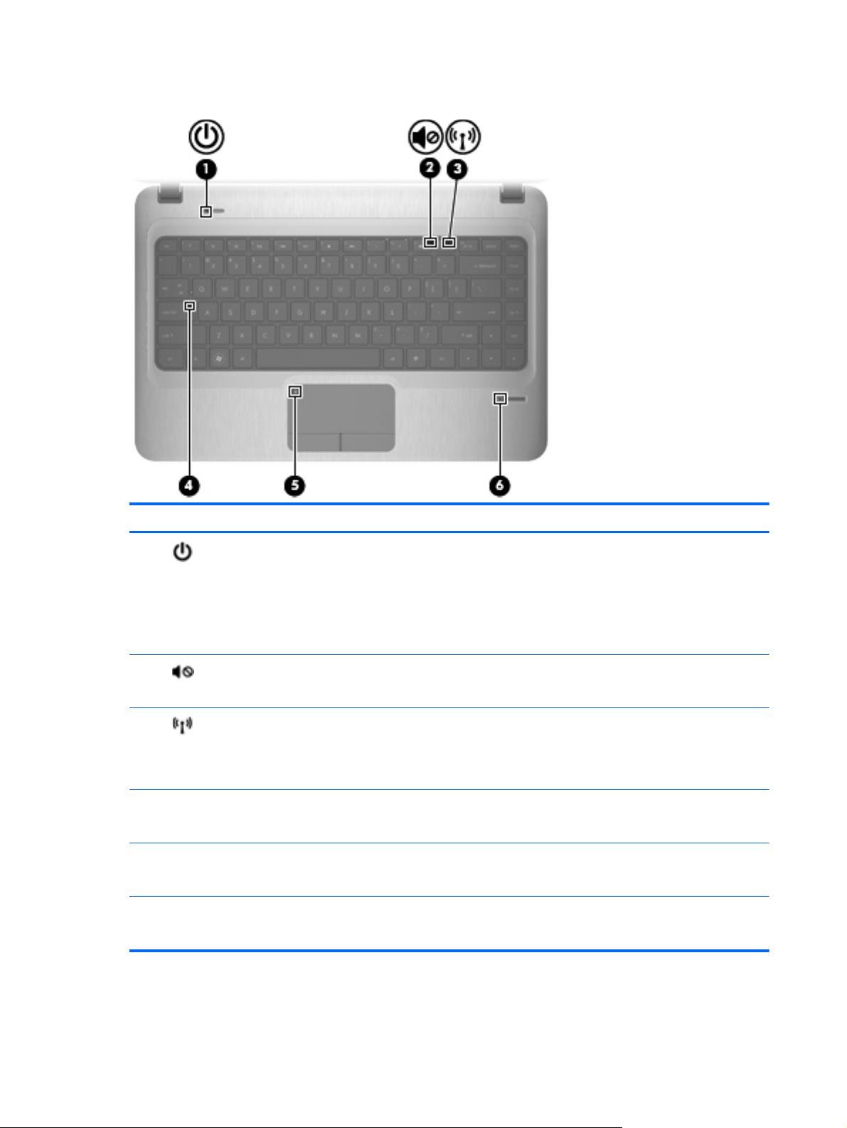
Lights
Component Description
(1)
(2)
(3)
(4) Caps lock light
(5) TouchPad light
(6) Fingerprint reader light
Power light
Mute light
Wireless light
White: Power is on.
●
● Blinking white: The computer is in the Sleep state.
Off: The computer is off or in Hibernation.
●
NOTE: Another power light is located on the left side of
the computer.
Amber: Computer sound is off.
●
● Off: Computer sound is on.
White: An integrated wireless device, such as a
●
wireless local area network (WLAN) device and/or a
Bluetooth® device, is on.
Amber: All wireless devices are off.
●
White: Caps lock is on.
●
● Off: Caps lock is off.
Amber: The TouchPad is off.
●
● Off: The TouchPad is on.
White: Fingerprint read is good.
●
6 Chapter 2 External component identification
● Amber: Fingerprint read is bad.
Page 15

Buttons
Component Description
(1)
(2) Fingerprint reader Allows a fingerprint logon to Windows, instead of a
Power button ● When the computer is off, press the button to turn on
the computer.
When the computer is on, press the button briefly to
●
initiate Sleep.
When the computer is in the Sleep state, press the
●
button briefly to exit Sleep.
● When the computer is in Hibernation, press the button
briefly to exit Hibernation.
If the computer has stopped responding and Windows®
shutdown procedures are ineffective, press and hold the
power button for at least 5 seconds to turn off the computer.
To learn more about your power settings, select Start >
Control Panel > System and Security > Power Options,
or refer to the HP Notebook Reference Guide.
password logon.
Top 7
Page 16
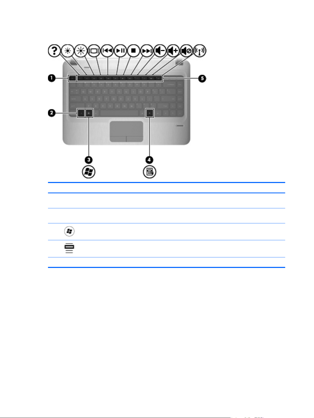
Keys
Component Description
(1) esc key Displays system information when pressed in combination
(2) fn key Executes frequently used system functions when pressed
(3)
(4)
(5) Action keys Execute frequently used system functions.
Windows logo key Displays the Windows Start menu.
Windows applications key Displays a shortcut menu for items beneath the pointer.
with the fn key.
in combination with the esc key.
8 Chapter 2 External component identification
Page 17

Front
Component Description
(1) Digital Media Slot Supports the following digital card formats:
(2) Speakers (2) Produce sound.
Right side
● MultiMedia card
● Secure Digital (SD) card
● Secure Digital High Capacity (SDHC) Memory card
(standard and large size)
Component Description
(1) Optical drive light
(2) Optical drive (select models only)
Optical drive weight saver option
(3)
(4) Battery light
(5)
USB ports (2) Connect optional USB devices.
Power connector Connects an AC adapter.
On: The optical drive is being accessed.
●
● Off: The optical drive is idle.
Reads and writes to an optical disc.
White: The computer is connected to external power
●
and the battery is fully charged.
● Amber: A battery is charging.
Blinking: The battery has reached a low or critical
●
battery level or there is a battery error.
Front 9
Page 18
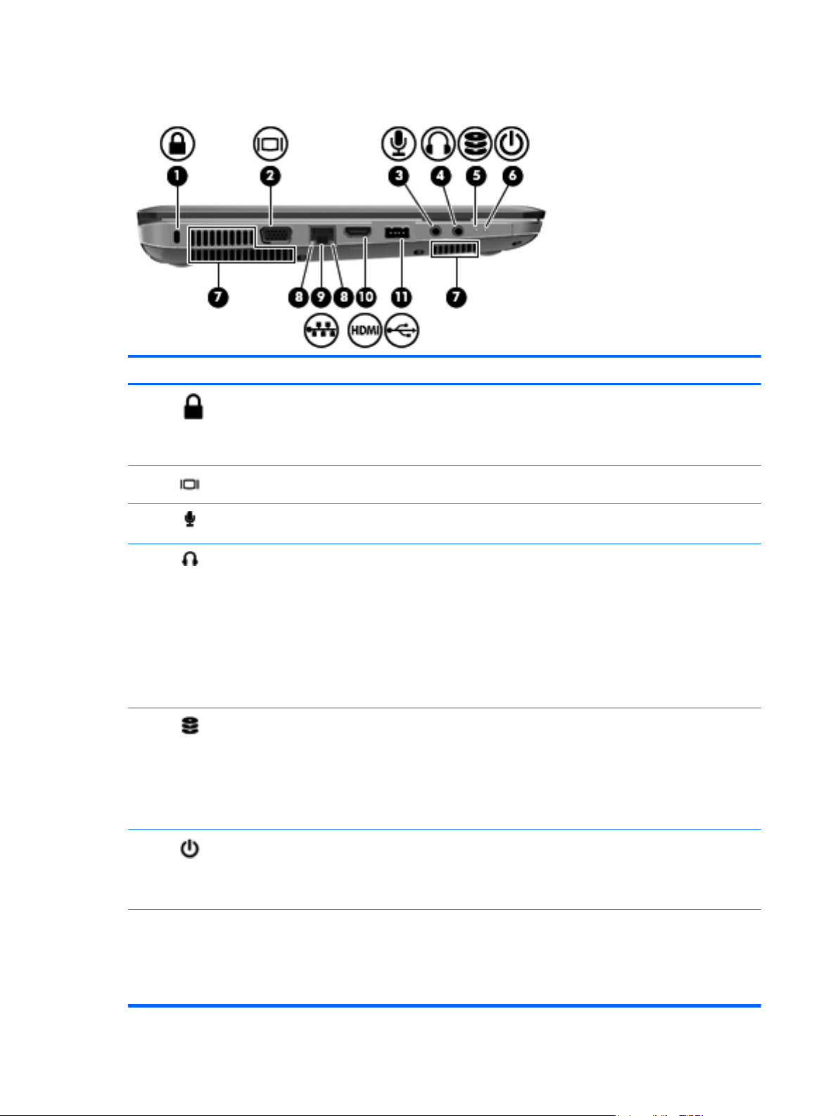
Left side
Component Description
(1)
(2)
(3)
(4)
(5)
Security cable slot Attaches an optional security cable to the computer.
NOTE: The security cable is designed to act as a
deterrent, but it may not prevent the computer from being
mishandled or stolen.
External monitor port Connects an external VGA monitor or projector.
Audio in (microphone) jack Connects an optional computer headset microphone,
stereo array microphone, or monaural microphone.
Audio-out (headphone) jack Produces sound when connected to optional powered
stereo speakers, headphones, ear buds, a headset, or
television audio.
WARNING! To reduce the risk of personal injury, adjust
the volume before putting on headphones, earbuds, or a
headset. For additional safety information, refer to the
Regulatory, Safety and Environmental Notices.
NOTE: When a device is connected to the jack, the
computer speakers are disabled.
Drive light
Blinking white: The hard drive is being accessed.
●
● Amber: HP ProtectSmart Hard Drive Protection has
temporarily parked the hard drive.
NOTE: For information on HP ProtectSmart Hard
Drive Protection, refer to the HP Notebook Reference
Guide.
(6)
(7) Vents (3) Enable airflow to cool internal components.
Power light ● White: The computer is on.
10 Chapter 2 External component identification
Blinking white: The computer is in the Sleep state.
●
Off: The computer is off or in Hibernation.
●
NOTE: The computer fan starts up automatically to cool
internal components and prevent overheating. It is normal
for the internal fan to cycle on and off during routine
operation.
Page 19

Component Description
(8) RJ-45 (network) lights
(9)
(10)
(11)
Display
White: The network is connected.
●
● Amber: The network is showing activity.
RJ-45 (network) jack Connects a network cable.
HDMI port Connects an optional video or audio device, such as a
high-definition television, or any compatible digital or audio
component.
USB port Connects optional USB devices.
Component Description
(1) WLAN antennas (2) Send and receive wireless signals to communicate with wireless
(2) Internal microphone Records sound.
(3) Webcam Records video and captures still photographs.
(4) Webcam light On: The webcam is in use.
*The antennas are not visible from the outside of the computer. For optimal transmission, keep the areas immediately
around the antennas free from obstructions. To see wireless regulatory notices, refer to the section of the Regulatory, Safety
and Environmental Notices that applies to your country or region. These notices are located in Help and Support.
local area networks (WLAN).
To use the webcam, select Start > All Programs > Cyberlink
Youcam.
Display 11
Page 20

Rear
Component Description
Vent Enables airflow to cool internal components.
Bottom
NOTE: The computer fan starts up automatically to cool internal
components and prevent overheating. It is normal for the internal fan
to cycle on and off during routine operation.
Component Description
(1) Battery bay Holds the battery.
(2)
(3) Vents (5) Enable airflow to cool internal components.
(4)
(5)
Battery release latch Releases the battery from the battery bay.
Hard drive bay Holds the hard drive.
Memory module compartment Contains the memory module slots.
12 Chapter 2 External component identification
NOTE: The computer fan starts up automatically to cool
internal components and prevent overheating. It is normal
for the internal fan to cycle on and off during routine
operation.
Page 21
3 Illustrated parts catalog
Serial number location
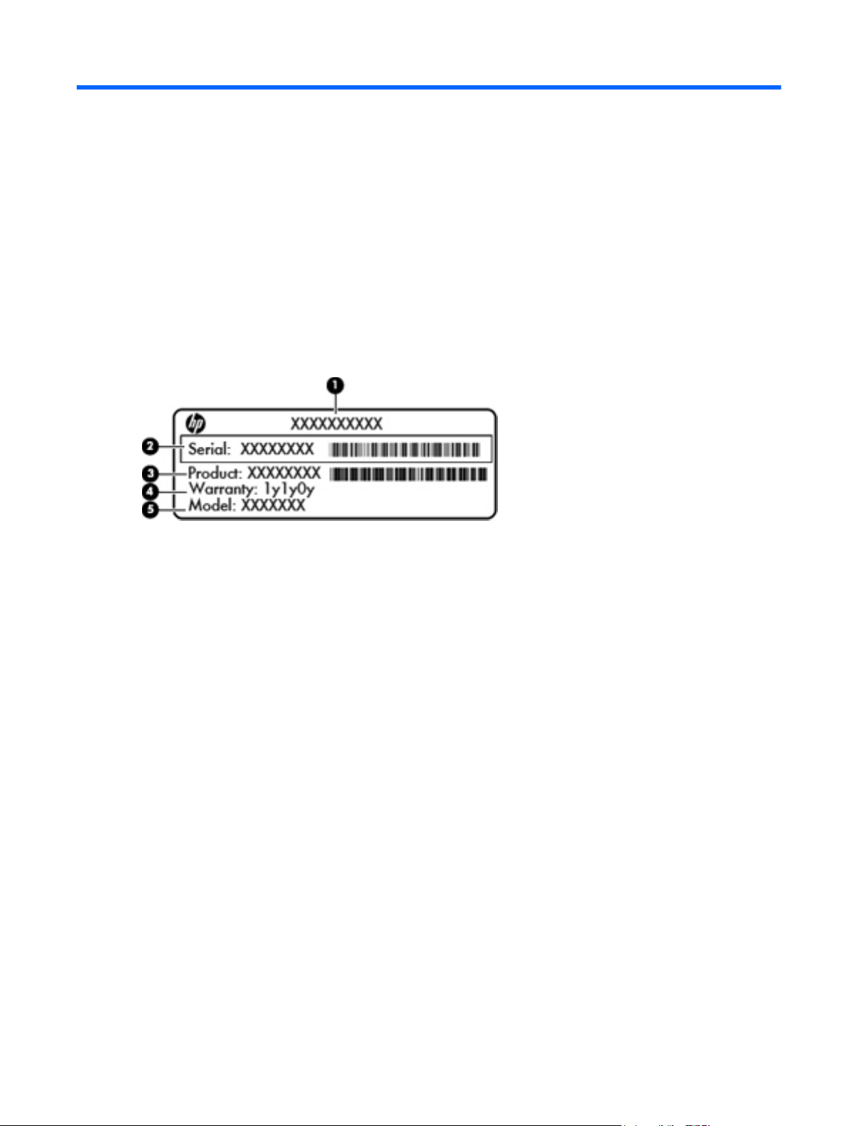
When ordering parts or requesting information, provide the computer serial number and model
number located in the battery bay of the computer.
Product name (1). This is the product name affixed to the front of the computer.
●
Serial number (s/n) (2). This is an alphanumeric identifier that is unique to each product.
●
Part number/Product number (p/n) (3). This number provides specific information about the
●
product's hardware components. The part number helps a service technician to determine what
components and parts are needed.
Warranty period (4). This number describes the duration (in years) of the warranty period for the
●
computer.
Model description (5). This is the alphanumeric identifier used to locate documents, drivers, and
●
support for the computer.
Serial number location 13
Page 22
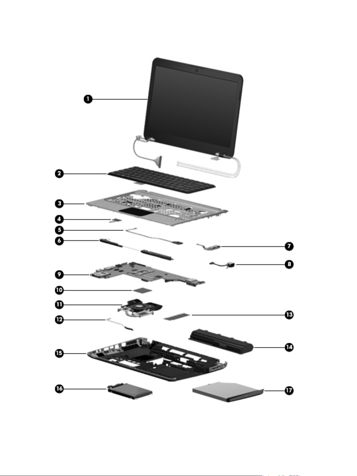
Computer major components
14 Chapter 3 Illustrated parts catalog
Page 23

Item Description Spare part number
(1) 35.56 cm (14.0 in), SVA, high-definition (HD), BrightView LED display assembly
NOTE: See
internal component spare part information.
For use in Dark Umber models 636941-001
For use in Steel Gray models 650675-001
(2) Keyboards
NOTE: For a detailed list of available keyboards, see
Standard 608222-xxx
QuickWeb 663563-xxx
(3) Top cover (includes TouchPad)
For use in Dark Umber models 636946-001
For use in Steel Gray models 650676-001
(4) Power button board (includes cable) 658706-001
(5) Fingerprint reader board 608225-001
(6) Speaker assembly (includes cable) 608232-001
(7) USB board (includes cable) 658707-001
(8) Power connector cable (includes power connector and cable) 608273-001
Display assembly components on page 19 for more display assembly
Sequential part number listing on page 23.
(9) System board (includes replacement thermal material)
For use in models equipped with 1 GB of discrete HD6470 graphics memory 636944-001
For use in models equipped with HM65 UMA graphics memory 636945-001
For use in models equipped with HM65 UMA graphics; includes Intel Core i3 2330M
For use in models equipped with HM65 UMA graphics memory; includes Intel Core i3
(10) Processor (includes replacement thermal material)
2nd Generation Intel Core i7 processor
● i7-2620M processor (2.7-Hz SC turbo up to 3.4 GHz), 4 MB L3 cache 35 W 631252-001
Intel Core i5 processors
● i5-2520M processor (2.5 GHz, SC turbo up to 3.2 GHz), 3 MB L3 cache, 35 W 631253-001
(11) Fan/heatsink assembly (includes replacement thermal material)
For use in UMA models in which the processor is not soldered to the system board 636940-001
processor
2310M processor
i5-2540M processor (2.6 GHz, SC turbo up to 3.3 GHz), 3 MB L3 cache, 35 W 631255-001
●
i5-2430M processor (2.4 GHz, SC turbo up to 3.3 GHz), 3 MB L3 cache, 35 W 653341-001
●
i5-2410M processor (2.3 GHz, SC turbo up to 2.9 GHz), 3 MB L3 cache, 35 W 638039-001
●
642732-001
656092-001
For use in UMA models in which the processor is soldered to the system board 642731-001
Computer major components 15
Page 24

Item Description Spare part number
For use in models equipped with discrete graphics 636939-001
(12) Bluetooth module
NOTE: The Bluetooth module cable is included in the Cable Kit, spare part number
608227-001.
WLAN modules (not illustrated)
Intel Centrino wireless-N 1000 802.11b/g/n 1x2 with WiDi support
For use in Argentina, Bolivia, Brazil, Canada (French/English), Chile, Columbia, Costa
Rica, Ecuador, El Salvador, Guadeloupe, Guatemala, Honduras, Mexico, Nicaragua,
Panama, Paraguay, Peru, the United States, Uruguay, and Venezuela.
Intel Centrino advanced wireless-N 1030 + Bluetooth® combo 802.11b/g/n 1x2
with WiDi support
For use in Algeria, Argentina, Bahrain, Belarus, Belgium, Bolivia, Brazil, Bulgaria,
Cameron, Canada (French/English), Chad, Chile, Columbia, Costa Rica, Croatia,
Cyprus, Ecuador, Egypt, El Salvador, Estonia, France, Guadeloupe, Guatemala,
Guyane Francaise, Honduras, Ivory Coast, Jordan, Kuwait, Latvia, Lebanon, Martinique,
Mayotte, Mexico, Montenegro, Morrocco, Nambia, Nicaragua, Nouvelle Caledoni,
Oman, Panama, Paraguay, Peru, Polynesie Francais, Portugal, Qatar, Reunion,
Romania, Russia, Sao Some & principe, Saudi Arabia, Senegal, South Africa, Spain, St.
Pierre et Miquel, Switzerland, the United States, Tunisia, Turkey, UAE, United Kingdom,
Uruguay, Venezuela, Wallis et Futuna, and Yemen.
Intel Centrino Advanced–N + WiMAX 6150, 802.11 b/g/n with WiDi support (+
Bluetooth
For use in the United States.
537921-001
593530-001
631956-001
633817-001
Realtek 8188GN 802.11b/g/n 1x1 WiFi Adapter
For use in Algeria, Argentina, Bahrain, Belarus, Belgium, Bolivia, Brazil, Bulgaria,
Cameron, Canada (French/English), Chad, Chile, Columbia, Costa Rica, Croatia,
Cyprus, Ecuador, Egypt, El Salvador, Estonia, France, Guadeloupe, Guatemala,
Guyane Francaise, Honduras, Ivory Coast, Jordan, Kuwait, Latvia, Lebanon, Martinique,
Mayotte, Mexico, Montenegro, Morrocco, Nambia, Nicaragua, Nouvelle Caledoni,
Oman, Panama, Paraguay, Peru, Polynesie Francais, Portugal, Qatar, Reunion,
Romania, Russia, Sao Some & principe, Saudi Arabia, Senegal, South Africa, Spain, St.
Pierre et Miquel, Switzerland, the United States, Tunisia, Turkey, UAE, United Kingdom,
Uruguay, Venezuela, Wallis et Futuna, and Yemen.
Ralink 5390GN 802.11 b/g/n 1x1 WiFi Adapter
For use in Algeria, Argentina, Bahrain, Belarus, Belgium, Bolivia, Brazil, Bulgaria,
Cameron, Canada (French/English), Chad, Chile, Columbia, Costa Rica, Croatia,
Cyprus, Ecuador, Egypt, El Salvador, Estonia, France, Guadeloupe, Guatemala,
Guyane Francaise, Honduras, Ivory Coast, Jordan, Kuwait, Latvia, Lebanon, Martinique,
Mayotte, Mexico, Montenegro, Morrocco, Nambia, Nicaragua, Nouvelle Caledoni,
Oman, Panama, Paraguay, Peru, Polynesie Francais, Portugal, Qatar, Reunion,
Romania, Russia, Sao Some & principe, Saudi Arabia, Senegal, South Africa, Spain, St.
Pierre et Miquel, Switzerland, the United States, Tunisia, Turkey, UAE, United Kingdom,
Uruguay, Venezuela, Wallis et Futuna, and Yemen.
640926-001
630703-001
16 Chapter 3 Illustrated parts catalog
Page 25

Item Description Spare part number
Atheros AR9002WB-1NGB 802.11 b/g/n 1x1 WiFi and Bluetooth 2.1+EDR Combo
Adapter (BT3.0+HS ready)
For use in Algeria, Argentina, Bahrain, Belarus, Belgium, Bolivia, Brazil, Bulgaria,
Cameron, Canada (French/English), Chad, Chile, Columbia, Costa Rica, Croatia,
Cyprus, Ecuador, Egypt, El Salvador, Estonia, France, Guadeloupe, Guatemala,
Guyane Francaise, Honduras, Ivory Coast, Jordan, Kuwait, Latvia, Lebanon, Martinique,
Mayotte, Mexico, Montenegro, Morrocco, Nambia, Nicaragua, Nouvelle Caledoni,
Oman, Panama, Paraguay, Peru, Polynesie Francais, Portugal, Qatar, Reunion,
Romania, Russia, Sao Some & principe, Saudi Arabia, Senegal, South Africa, Spain, St.
Pierre et Miquel, Switzerland, the United States, Tunisia, Turkey, UAE, United Kingdom,
Uruguay, Venezuela, Wallis et Futuna, and Yemen.
Realtek RTL8188CE 802.11 b/g/n WiFi with Realtek CSRBC4 Bluetooth 2.1+EDR
Adapter
For use in Algeria, Argentina, Bahrain, Belarus, Belgium, Bolivia, Brazil, Bulgaria,
Cameron, Canada (French/English), Chad, Chile, Columbia, Costa Rica, Croatia,
Cyprus, Ecuador, Egypt, El Salvador, Estonia, France, Guadeloupe, Guatemala,
Guyane Francaise, Honduras, Ivory Coast, Jordan, Kuwait, Latvia, Lebanon, Martinique,
Mayotte, Mexico, Montenegro, Morrocco, Nambia, Nicaragua, Nouvelle Caledoni,
Oman, Panama, Paraguay, Peru, Polynesie Francais, Portugal, Qatar, Reunion,
Romania, Russia, Sao Some & principe, Saudi Arabia, Senegal, South Africa, Spain, St.
Pierre et Miquel, Switzerland, the United States, Tunisia, Turkey, UAE, United Kingdom,
Uruguay, Venezuela, Wallis et Futuna, and Yemen.
Broadcom 4313/2070 802.11b/g/n (1x1) and Bluetooth high-speed Half Mini Card
For use in Afghanistan, Albania, Algeria, Andorra, Angola, Antigua and Barbuda,
Argentina, Armenia, Aruba, Australia, Austria, Azerbaijan, Bahamas, Bahrain,
Bangladesh, Barbados, Belarus, Belgium, Belize, Benin, Bermuda, Bhutan, Bolivia,
Bosnia and Herzegovina, Botswana, Brazil, the British Virgin Islands, Brunei, Bulgaria,
Burkina Faso, Burundi, Cambodia, Cameroon, Canada, Cape Verde, the Cayman
Islands, Central African Republic, Chad, Chile, the People's Republic of China,
Colombia, Comoros, Congo, Costa Rica, Croatia, Cyprus, Czech Republic, Denmark,
Djibouti, Dominica, the Dominican Republic, East Timor, Ecuador, Egypt, El Salvador,
Equitorial Guinea, Eritrea, Estonia, Ethiopia, Fiji, Finland, France, French Guiana,
Gabon, Gambia, Georgia, Germany, Ghana, Gibraltar, Greece, Grenada, Guadeloupe,
Guam, Guatemala, Guinea, Guinea-Bissa, Guyana, Haiti, Honduras, Hong Kong,
Hungary, Iceland, India, Indonesia, Iraq, Ireland, Israel, Italy, Ivory Coast, Jamaica,
Japan, Jordan, Kazakhstan, Kenya, Kiribati, Kuwait, Kyrgyzstan, Laos, Latvia, Lebanon,
Lesotho, Liberia, Liechtenstein, Lithuania, Luxembourg, Macedonia, Madagascar,
Malawi, Malaysia, Maldives, Mali, Malta, Marshall Islands, Martinique, Mauritania,
Mauritius, Mexico, Micronesia, Monaco, Mongolia, Montenegro, Morocco, Mozambique,
Namibia, Nauru, Nepal, the Nether Antilles, the Netherlands, New Zealand, Nicaragua,
Niger, Nigeria, Norway, Oman, Pakistan, Palau, Panama, Papua New Guinea,
Paraguay, Peru, Philippines, Poland, Portugal, Puerto Rico, Qatar, the Republic of
Moldova, Romania, Russia, Rwanda, Samoa, San Marino, Sao Tome and Principe,
Saudi Arabia, Senegal, Serbia and Montenegro, Seychelles, Sierra Leone, Singapore,
Slovakia, Slovenia, Solomon Islands, Somalia, South Africa, South Korea, Sri Lanka, St.
Kitts and Nevis, St. Lucia, St. Vincent and the Grenadines, Suriname, Swaziland,
Sweden, Switzerland, Taiwan, Tajikistan, Tanzania, Thailand, Togo, Tonga, Trinidad
and Tobago, Tunisia, Turkey, Turkmenistan, Tuvalu, Uganda, Ukraine, the United Arab
Emirates, the United Kingdom, the United States, Uruguay, the US Virgin Islands,
Uzbekistan, Vanuatu, Venezuela, Vietnam, Yemen, Zaire, Zambia, and Zimbabwe
593127-001
602993-001
600370-001
Atheros 9485GN 802.11b/g/n 1x1 WiFi and 3012 Bluetooth 4.0 Combo Adapter 655795-001
Broadcom 4313GN 802.11b/g/n 1x1 WiFi and 20702 Bluetooth 4.0 Combo Adapter 657325-001
(13) Memory modules (PC3-10600, 1333 MHz)
2 GB 621565-001
Computer major components 17
Page 26

Item Description Spare part number
4 GB 621569-001
(14) Battery
9-cell, 100 WHr (3.0 Ah) Li-ion 636631-001
6-cell, 62 WHr (2.80 Ah) Li-ion 593562-001
6-cell, 55 WHr (2.55 Ah) Li-ion 593554-001
(15) Base enclosure (includes modem cable and optical drive cable) 636937-001
(16) Hard drive (includes hard drive bracket)
NOTE: The hard drive cable is included in the Cable Kit, spare part number 608227-001.
750 GB, 7200 rpm 678103-001
640 GB, 7200 rpm 678102-001
500 GB, 7200 rpm 678101-001
320 GB, 7200 rpm 678100-001
160 GB solid-state drive 608215-001
(17) DVD±RW SuperMulti DL Drive (12.7 mm optical drive, fixed) (select models only) 677742-001
Optical drive weight saver (not illustrated) 660550-001
18 Chapter 3 Illustrated parts catalog
Page 27

Display assembly components
Item Description Spare part number
(1) Display bezel 636938-001
(2) Webcam module 615744-001
(3) Display panel (35.56 cm (14.0 in) Brightview, high-definition; includes display panel
cable)
Display Cable Kit 608211-001
(4a) Webcam cable
608206-001
Display assembly components 19
Page 28
Item Description Spare part number
(4b) Antennas and cables
(5) Display hinge covers 608210-001
(6) Display bracket 608214-001
(7) Display back cover
For use in Dark Umber computer models 636936-001
For use in Steel Gray computer models 650674-001
Display Screw Kit (not illustrated; includes screws and screw covers) 608212-001
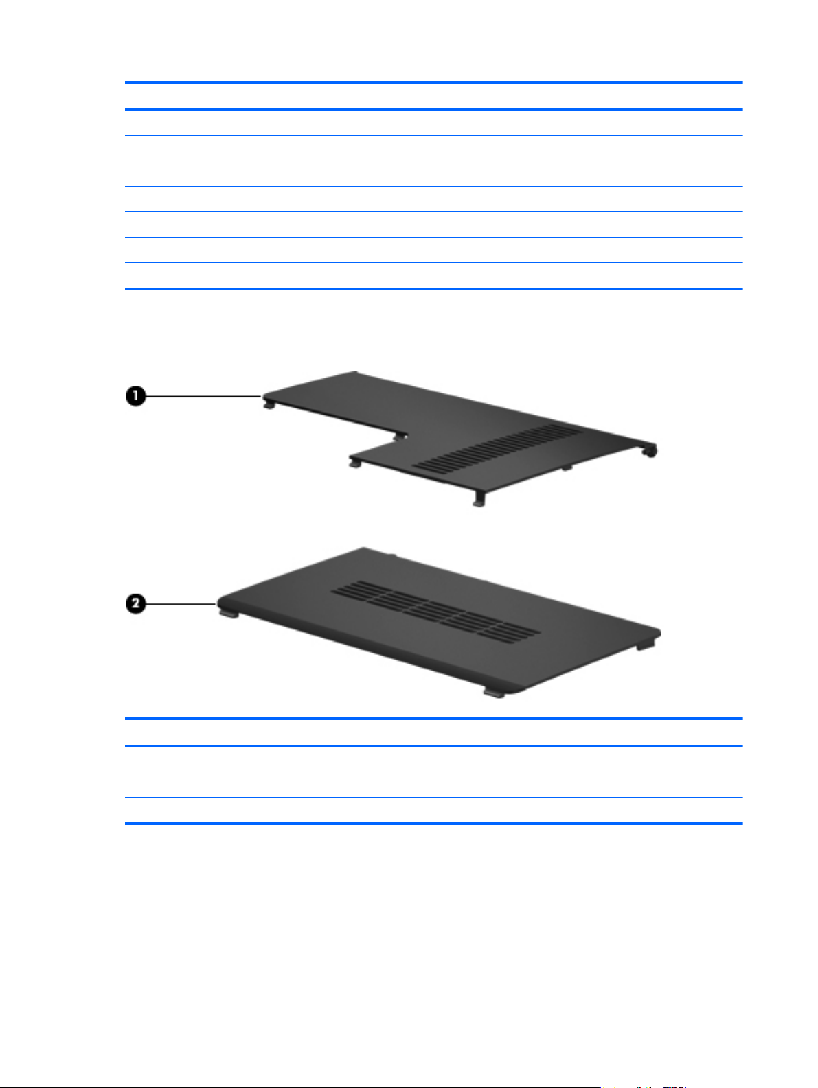
Plastics Kit
Item Description Spare part number
Plastics Kit 636942-001
(1) Wireless/memory module mini-card compartment cover (includes captive screw)
(2) Hard drive bay cover (includes captive screws)
20 Chapter 3 Illustrated parts catalog
Page 29

Mass storage devices
Item Description Spare part number
(1) Optical drive (12.7 mm, SATA, fixed)
DVD±RW SuperMulti DL Drive (select models only) 677742-001
Optical drive weight saver 660550-001
(2) Hard drive (include hard drive bracket)
NOTE: The hard drive cable is included in the Cable Kit, spare part number 608227-001.
750 GB, 7200 rpm 678103-001
640 GB, 7200 rpm 678102-001
500 GB, 7200 rpm 678101-001
320 GB, 7200 rpm 678100-001
160 GB solid-state drive (not illustrated) 608215-001
Hard drive mounting hardware 672516-001
Mass storage devices 21
Page 30

Miscellaneous parts
Description Spare part number
AC adapters
90 W Smart AC adapter, RC/V 3W 609940-001
65 W Smart AC adapter, RC/V 3W 609939-001
Power cord, AC, 3 wire, black, 1.83 m
For use in Argentina 490371-D01
For use in Brazil 490371-202
For use in the People's Republic of China 490371-AA1
For use in Denmark 490371-081
For use in Europe, the Middle East, and Africa 490371-021
For use in Italy 490371-061
For use in North America 490371-001
For use in Switzerland 490371-111
For use in the United Kingdom and Singapore 490371-031
Thermal pad kit 634366-001
RTC battery 449137-001
Rubber feet 608228-001
Screw Kit
Phillips M2.0x2.0 broadhead screw
●
Phillips M2.0x3.0 screw
●
● Phillips M2.0x4.0 screw
Phillips M2.0x5.0 screw
●
Phillips M2.5x5.0 screw
●
● Phillips M2.5x6.5 screw
● Phillips M2.5x7.0 screw
Phillips M3.0x3.0 screw
●
608234-001
22 Chapter 3 Illustrated parts catalog
Page 31

Sequential part number listing
Spare part
number
449137-001 RTC battery
490371-001 Power cord, AC, 3-pin, black, 1.83 m, for use in North America
490371-021 Power cord, AC, 3-pin, black, 1.83 m, for use in Europe, the Middle East, and Africa
490371-031 Power cord, AC, 3-pin, black, 1.83 m, for use in the United Kingdom and Singapore
490371-061 Power cord, AC, 3-pin, black, 1.83 m, for use in Italy
490371-081 Power cord, AC, 3-pin, black, 1.83 m, for use in Denmark
490371-111 Power cord, AC, 3-pin, black, 1.83 m, for use in Switzerland
490371-202 Power cord, AC, 3-pin, black, 1.83 m, for use in Brazil
490371-D01 Power cord, AC, 3-pin, black, 1.83 m, for use in Argentina
537921-001 Bluetooth module without cable (For use in the United States)
593127-001 Atheros AR9002WB-1NGB 802.11 b/g/n 1x1 WiFi and Bluetooth 2.1+EDR Combo Adapter (BT3.0+HS
Description
ready)
For use in Albania, Algeria, Andorra, Angola, Argentina, Azerbaijan, Austria, Bahrain, Belarus,
Belgium, Bolivia, Bosnia, Botswana, Brazil, Bulgaria, Cameroon, Canada (French/English), Chad,
Chile, Columbia, Costa Rica, Croatia, Cyprus, Czech Republic, Denmark, Ecuador, Egypt, El Salvador,
Estonia, Finland, France, Georgia, Germany, Ghana, Gibraltar, Greece, Guadeloupe, Guatemala,
Guyane Francaise, Honduras, Hungary, Iceland, Israel, Italy, Ivory Coast, Jordan, Kazakhstan, Kenya,
Kuwait, Latvia, Lebanon, Liberia, Libya, Liechtenstein, Lithuania, Luxembourg, Macedonia, Martinique,
Mayotte, Mauritius, Mexico, Moldova, Monaco, Montenegro, Morocco, Nambia, Netherlands,
Nicaragua, Nigeria, Norway, Nouvelle Caledoni, Oman, Panama, Paraguay, Peru, Poland, Polynesie
Francais, Portugal, Qatar, Reunion, Romania, Russia, San Marino, Sao Tome and principe, Saudi
Arabia, Senegal, Slovenia, South Africa, Spain, St. Pierre et Miquel, Swaziland, Sweden, Switzerland,
Tanzania, the United States, Tunisia, Turkey, UAE, Uganda, United Kingdom, Uruguay, Venezuela,
Wallis et Futuna, and Yemen.
593530-001 Intel Centrino wireless-N 1000 802.11b/g/n 1x2 with WiDi support
For use in Argentina, Bolivia, Brazil, Canada (French/English), Chile, Columbia, Costa Rica, Ecuador,
El Salvador, Guadeloupe, Guatemala, Honduras, Mexico, Nicaragua, Panama, Paraguay, Peru, the
United States, Uruguay, and Venezuela.
593554-001 6-cell, 55 WH (2.55 Ah) Li-ion battery
593562-001 6-cell, 62 WH (2.80 Ah) Li-ion battery
Sequential part number listing 23
Page 32

Spare part
number
Description
600370-001 Broadcom 4313/2070 802.11b/g/n (1x1) and Bluetooth high-speed Half Mini Card for use in
602993-001 Realtek RTL8188CE 802.11 b/g/n WiFi with Realtek CSRBC4 Bluetooth 2.1 + EDR Adapter
Afghanistan, Albania, Algeria, Andorra, Angola, Antigua and Barbuda, Argentina, Armenia, Aruba,
Australia, Austria, Azerbaijan, Bahamas, Bahrain, Bangladesh, Barbados, Belarus, Belgium, Belize,
Benin, Bermuda, Bhutan, Bolivia, Bosnia and Herzegovina, Botswana, Brazil, the British Virgin Islands,
Brunei, Bulgaria, Burkina Faso, Burundi, Cambodia, Cameroon, Canada, Cape Verde, the Cayman
Islands, Central African Republic, Chad, Chile, the People's Republic of China, Colombia, Comoros,
Congo, Costa Rica, Croatia, Cyprus, Czech Republic, Denmark, Djibouti, Dominica, the Dominican
Republic, East Timor, Ecuador, Egypt, El Salvador, Equitorial Guinea, Eritrea, Estonia, Ethiopia, Fiji,
Finland, France, French Guiana, Gabon, Gambia, Georgia, Germany, Ghana, Gibraltar, Greece,
Grenada, Guadeloupe, Guam, Guatemala, Guinea, Guinea-Bissa, Guyana, Haiti, Honduras, Hong
Kong, Hungary, Iceland, India, Indonesia, Iraq, Ireland, Israel, Italy, Ivory Coast, Jamaica, Japan,
Jordan, Kazakhstan, Kenya, Kiribati, Kuwait, Kyrgyzstan, Laos, Latvia, Lebanon, Lesotho, Liberia,
Liechtenstein, Lithuania, Luxembourg, Macedonia, Madagascar, Malawi, Malaysia, Maldives, Mali,
Malta, Marshall Islands, Martinique, Mauritania, Mauritius, Mexico, Micronesia, Monaco, Mongolia,
Montenegro, Morocco, Mozambique, Namibia, Nauru, Nepal, the Nether Antilles, the Netherlands,
New Zealand, Nicaragua, Niger, Nigeria, Norway, Oman, Pakistan, Palau, Panama, Papua New
Guinea, Paraguay, Peru, Philippines, Poland, Portugal, Puerto Rico, Qatar, the Republic of Moldova,
Romania, Russia, Rwanda, Samoa, San Marino, Sao Tome and Principe, Saudi Arabia, Senegal,
Serbia and Montenegro, Seychelles, Sierra Leone, Singapore, Slovakia, Slovenia, Solomon Islands,
Somalia, South Africa, South Korea, Sri Lanka, St. Kitts and Nevis, St. Lucia, St. Vincent and the
Grenadines, Suriname, Swaziland, Sweden, Switzerland, Taiwan, Tajikistan, Tanzania, Thailand,
Togo, Tonga, Trinidad and Tobago, Tunisia, Turkey, Turkmenistan, Tuvalu, Uganda, Ukraine, the
United Arab Emirates, the United Kingdom, the United States, Uruguay, the US Virgin Islands,
Uzbekistan, Vanuatu, Venezuela, Vietnam, Yemen, Zaire, Zambia, and Zimbabwe
For use in Albania, Algeria, Andorra, Angola, Argentina, Azerbaijan, Austria, Bahrain, Belarus,
Belgium, Bolivia, Bosnia, Botswana, Brazil, Bulgaria, Cameroon, Canada (French/English), Chad,
Chile, Columbia, Costa Rica, Croatia, Cyprus, Czech Republic, Denmark, Ecuador, Egypt, El Salvador,
Estonia, Finland, France, Georgia, Germany, Ghana, Gibraltar, Greece, Guadeloupe, Guatemala,
Guyane Francaise, Honduras, Hungary, Iceland, Israel, Italy, Ivory Coast, Jordan, Kazakhstan, Kenya,
Kuwait, Latvia, Lebanon, Liberia, Libya, Liechtenstein, Lithuania, Luxembourg, Macedonia, Martinique,
Mayotte, Mauritius, Mexico, Moldova, Monaco, Montenegro, Morocco, Nambia, Netherlands,
Nicaragua, Nigeria, Norway, Nouvelle Caledoni, Oman, Panama, Paraguay, Peru, Poland, Polynesie
Francais, Portugal, Qatar, Reunion, Romania, Russia, San Marino, Sao Tome and principe, Saudi
Arabia, Senegal, Slovenia, South Africa, Spain, St. Pierre et Miquel, Swaziland, Sweden, Switzerland,
Tanzania, the United States, Tunisia, Turkey, UAE, Uganda, United Kingdom, Uruguay, Venezuela,
Wallis et Futuna, and Yemen..
608206-001 Display panel, 35.56 cm (14.0 in), high definition, Brightview
608210-001 Display hinge cover
608211-001 Display Cable Kit
608212-001 Display Screw Kit
608214-001 Display bracket (with hinges)
608215-001 Hard drive, 160 GB, solid state
677742-001 DVD±RW SuperMulti DL Drive (select models only)
608222-001 Keyboard for use in the United States
608222-031 Keyboard for use in the United Kingdom
608222-041 Keyboard for use in Germany
608222-051 Keyboard for use in France
608222-071 Keyboard for use in Spain
24 Chapter 3 Illustrated parts catalog
Page 33

Spare part
number
608222-121 Keyboard for use in English and French Canada
608222-131 Keyboard for use in Portugal
608222-141 Keyboard for use in Turkey
608222-161 Keyboard for use in Latin America
608222-171 Keyboard for use in Saudi Arabia
608222-201 Keyboard for use in Brazil
608222–251 Keyboard for use in Russia
608222-B31 Keyboard for use in Europe, the Middle East, and Africa
608222-BG1 Keyboard for use in Switzerland
608222-DH1 Keyboard for use in the Netherlands
608225-001 Fingerprint reader board
608227-001 Cable Kit (includes Bluetooth module cable and hard drive cable)
608228-001 Rubber Feet Kit
608232-001 Speaker assembly (includes cable)
608234-001 Screw Kit
Description
608273-001 Power connector with cable
609939-001 65 W Smart AC adapter, RC/V 3W
609940-001 90 W Smart AC adapter, RC/V 3W
615744-001 Webcam module
621565-001 Memory module, 2 GB (PC3 10600 1333 Mhz)
621569-001 Memory module, 4 GB (PC3 10600 1333 Mhz)
630703-001 Ralink 5390GN 802.11 b/g/n 1x1 WiFi Adapter
For use in Albania, Algeria, Andorra, Angola, Argentina, Azerbaijan, Austria, Bahrain, Belarus,
Belgium, Bolivia, Bosnia, Botswana, Brazil, Bulgaria, Cameroon, Canada (French/English), Chad,
Chile, Columbia, Costa Rica, Croatia, Cyprus, Czech Republic, Denmark, Ecuador, Egypt, El Salvador,
Estonia, Finland, France, Georgia, Germany, Ghana, Gibraltar, Greece, Guadeloupe, Guatemala,
Guyane Francaise, Honduras, Hungary, Iceland, Israel, Italy, Ivory Coast, Jordan, Kazakhstan, Kenya,
Kuwait, Latvia, Lebanon, Liberia, Libya, Liechtenstein, Lithuania, Luxembourg, Macedonia, Martinique,
Mayotte, Mauritius, Mexico, Moldova, Monaco, Montenegro, Morocco, Nambia, Netherlands,
Nicaragua, Nigeria, Norway, Nouvelle Caledoni, Oman, Panama, Paraguay, Peru, Poland, Polynesie
Francais, Portugal, Qatar, Reunion, Romania, Russia, San Marino, Sao Tome and principe, Saudi
Arabia, Senegal, Slovenia, South Africa, Spain, St. Pierre et Miquel, Swaziland, Sweden, Switzerland,
Tanzania, the United States, Tunisia, Turkey, UAE, Uganda, United Kingdom, Uruguay, Venezuela,
Wallis et Futuna, and Yemen.
631252-001 Intel Core i7 2620M Dual-Core processor (2.7 GHz, SC turbo up to 3.40 GHz, 4 MB L3 cache, 35 W)
631253-001 Intel Core i5 2520M Dual-Core processor (2.5 GHz,, SC turbo up to 3.20 GHz, 3 MB, L3 cache 35 W)
631255-001 Intel Core i5 2540M Dual-Core processor (2.6 GHz,, SC turbo up to 3.33 GHz, 3 MB, L3 cache 35 W)
Sequential part number listing 25
Page 34

Spare part
number
631956-001 Intel Centrino advanced wireless-N 1030 + Bluetooth® combo 802.11b/g/ n 1x2 with WiDi support
633817-001 Intel Centrino Advanced-N + WiMAX 6150 with WIDI support (+ Bluetooth)
634366-001 Thermal pad kit
636631-001 9-cell, 100 WH (3.0 Ah) Li-ion battery
636936-001 Display back cover for use in Dark Umber computer models
636937-001 Base enclosure
636938-001 Display bezel
Description
For use in Albania, Algeria, Andorra, Angola, Argentina, Azerbaijan, Austria, Bahrain, Belarus,
Belgium, Bolivia, Bosnia, Botswana, Brazil, Bulgaria, Cameroon, Canada (French/English), Chad,
Chile, Columbia, Costa Rica, Croatia, Cyprus, Czech Republic, Denmark, Ecuador, Egypt, El Salvador,
Estonia, Finland, France, Georgia, Germany, Ghana, Gibraltar, Greece, Guadeloupe, Guatemala,
Guyane Francaise, Honduras, Hungary, Iceland, Israel, Italy, Ivory Coast, Jordan, Kazakhstan, Kenya,
Kuwait, Latvia, Lebanon, Liberia, Libya, Liechtenstein, Lithuania, Luxembourg, Macedonia, Martinique,
Mayotte, Mauritius, Mexico, Moldova, Monaco, Montenegro, Morocco, Nambia, Netherlands,
Nicaragua, Nigeria, Norway, Nouvelle Caledoni, Oman, Panama, Paraguay, Peru, Poland, Polynesie
Francais, Portugal, Qatar, Reunion, Romania, Russia, San Marino, Sao Tome and principe, Saudi
Arabia, Senegal, Slovenia, South Africa, Spain, St. Pierre et Miquel, Swaziland, Sweden, Switzerland,
Tanzania, the United States, Tunisia, Turkey, UAE, Uganda, United Kingdom, Uruguay, Venezuela,
Wallis et Futuna, and Yemen.
For use in the United States.
636939-001 Fan/heat sink assembly for use in models with discrete graphics (includes replacement thermal
636940-001 Fan/heat sink assembly for use in UMA models in which the processor is not soldered to the system
636941-001 Display assembly, 35.56 cm (14.0 in), SVA, high-definition (HD), BrightView LED for use in Dark
636942-001 Plastics Kit
636944-001 System board (includes replacement thermal material) for use in models equipped with 1 GB of
636945-001 System board for use in models equipped with HM65 UMA graphics memory
636946-001 Top cover for use in Dark Umber models (includes TouchPad and bracket, button board, and cable)
638039-001 Intel Core i5-2410M processor (2.3 GHz, turbo up to 2.9 GHz, 3 MB, L3 cache 35 W)
640926-001 Realtek RTL8191SE 802.11 b/g/n WiFi Adapter
material)
board (includes replacement thermal material)
Umber models
HD6470 discrete graphics memory
For use in Albania, Algeria, Andorra, Angola, Argentina, Azerbaijan, Austria, Bahrain, Belarus,
Belgium, Bolivia, Bosnia, Botswana, Brazil, Bulgaria, Cameroon, Canada (French/English), Chad,
Chile, Columbia, Costa Rica, Croatia, Cyprus, Czech Republic, Denmark, Ecuador, Egypt, El Salvador,
Estonia, Finland, France, Georgia, Germany, Ghana, Gibraltar, Greece, Guadeloupe, Guatemala,
Guyane Francaise, Honduras, Hungary, Iceland, Israel, Italy, Ivory Coast, Jordan, Kazakhstan, Kenya,
Kuwait, Latvia, Lebanon, Liberia, Libya, Liechtenstein, Lithuania, Luxembourg, Macedonia, Martinique,
Mayotte, Mauritius, Mexico, Moldova, Monaco, Montenegro, Morocco, Nambia, Netherlands,
Nicaragua, Nigeria, Norway, Nouvelle Caledoni, Oman, Panama, Paraguay, Peru, Poland, Polynesie
Francais, Portugal, Qatar, Reunion, Romania, Russia, San Marino, Sao Tome and principe, Saudi
Arabia, Senegal, Slovenia, South Africa, Spain, St. Pierre et Miquel, Swaziland, Sweden, Switzerland,
Tanzania, the United States, Tunisia, Turkey, UAE, Uganda, United Kingdom, Uruguay, Venezuela,
Wallis et Futuna, and Yemen.
26 Chapter 3 Illustrated parts catalog
Page 35

Spare part
number
Description
642731-001 Fan/heat sink for use in UMA models in which the processor is soldered to the system board (includes
642732-001 System board for use in models equipped with HM65 UMA graphics memory; includes Intel Core
650674-001 Display back cover for use in Steel Gray computer models
650675-001 Display assembly, 35.56 cm (14.0-in), SVA, high-definition (HD), BrightView, LED for use in Steel Gray
650676-001 Top cover for use in Steel Gray models (includes TouchPad and bracket, button board, and cable)
653341-001 Intel Core i5-2430M processor (2.4 GHz, turbo up to 2.9 GHz), 3 MB, L3 cache 35 W
655795-001 Atheros 9485GN 802.11b/g/n 1x1 WiFi and 3012 Bluetooth 4.0 Combo Adapter
656092-001 System board for use in models equipped with HM65 UMA graphics memory; includes Intel Core
657325-001 Broadcom 4313GN 802.11b/g/n 1x1 WiFi and 20702 Bluetooth 4.0 Combo Adapter
658706-001 Power button board (includes cable)
658707-001 USB board with cable
660550-001 Optical drive weight saver
663563-001 QuickWeb keyboard for use in the United States
663563-031 QuickWeb keyboard for use in the United Kingdom
replacement thermal material)
i3-2330M processor
models
i3-2310M processor
663563-041 QuickWeb keyboard for use in Germany
663563-051 QuickWeb keyboard for use in France
663563-061 QuickWeb keyboard for use in Italy
663563-071 QuickWeb keyboard for use in Spain
663563-121 QuickWeb keyboard for use in French Canada
663563-131 QuickWeb keyboard for use in Portugal
663563-141 QuickWeb keyboard for use in Turkey
663563-161 QuickWeb keyboard for use in Latin America
663563-171 QuickWeb keyboard for use in Saudi Arabia
663563-201 QuickWeb keyboard for use in Brazil
663563-251 QuickWeb keyboard for use in Russia
663563-A41 QuickWeb keyboard for use in Belgium
663563-B31 QuickWeb keyboard for use internationally
663563-BG1 QuickWeb keyboard for use in Switzerland
663563-DH1 QuickWeb keyboard for use in the Netherlands
672516-001 Hard drive mounting hardware
677742-001 DVD±RW SuperMulti DL Drive (select models only)
Sequential part number listing 27
Page 36

Spare part
number
678100-001 320 GB, 7200 rpm hard drive
678101-001 500 GB, 7200 rpm hard drive
678102-001 640 GB, 7200 rpm hard drive
678103-001 750 GB, 7200 rpm hard drive
Description
28 Chapter 3 Illustrated parts catalog
Page 37

4 Removal and replacement procedures
Preliminary replacement requirements
Tools required
You will need the following tools to complete the removal and replacement procedures:
● Flat-bladed screwdriver
● Magnetic screwdriver
Phillips P0 and P1 screwdrivers
●
Service considerations
The following sections include some of the considerations that you must keep in mind during
disassembly and assembly procedures.
NOTE: As you remove each subassembly from the computer, place the subassembly (and all
accompanying screws) away from the work area to prevent damage.
Plastic parts
Using excessive force during disassembly and reassembly can damage plastic parts. Use care when
handling the plastic parts. Apply pressure only at the points designated in the maintenance
instructions.
Preliminary replacement requirements 29
Page 38

Cables and connectors
CAUTION: When servicing the computer, be sure that cables are placed in their proper locations
during the reassembly process. Improper cable placement can damage the computer.
Cables must be handled with extreme care to avoid damage. Apply only the tension required to
unseat or seat the cables during removal and insertion. Handle cables by the connector whenever
possible. In all cases, avoid bending, twisting, or tearing cables. Be sure that cables are routed in
such a way that they cannot be caught or snagged by parts being removed or replaced. Handle flex
cables with extreme care; these cables tear easily.
Drive handling
CAUTION: Drives are fragile components that must be handled with care. To prevent damage to
the computer, damage to a drive, or loss of information, observe these precautions:
Before removing or inserting a hard drive, shut down the computer. If you are unsure whether the
computer is off or in Hibernation, turn the computer on, and then shut it down through the operating
system.
Before handling a drive, be sure that you are discharged of static electricity. While handling a drive,
avoid touching the connector.
Before removing a diskette drive or optical drive, be sure that a diskette or disc is not in the drive and
be sure that the optical drive tray is closed.
Handle drives on surfaces covered with at least one inch of shock-proof foam.
Avoid dropping drives from any height onto any surface.
After removing a hard drive, an optical drive, or a diskette drive, place it in a static-proof bag.
Avoid exposing a hard drive to products that have magnetic fields, such as monitors or speakers.
Avoid exposing a drive to temperature extremes or liquids.
If a drive must be mailed, place the drive in a bubble pack mailer or other suitable form of protective
packaging and label the package “FRAGILE.”
30 Chapter 4 Removal and replacement procedures
Page 39

Grounding guidelines
Electrostatic discharge damage
Electronic components are sensitive to electrostatic discharge (ESD). Circuitry design and structure
determine the degree of sensitivity. Networks built into many integrated circuits provide some
protection, but in many cases, ESD contains enough power to alter device parameters or melt
silicon junctions.
A discharge of static electricity from a finger or other conductor can destroy static-sensitive devices or
microcircuitry. Even if the spark is neither felt nor heard, damage may have occurred.
An electronic device exposed to ESD may not be affected at all and can work perfectly throughout a
normal cycle. Or the device may function normally for a while, then degrade in the internal layers,
reducing its life expectancy.
CAUTION: To prevent damage to the computer when you are removing or installing internal
components, observe these precautions:
Keep components in their electrostatic-safe containers until you are ready to install them.
Use nonmagnetic tools.
Before touching an electronic component, discharge static electricity by using the guidelines
described in this section.
Avoid touching pins, leads, and circuitry. Handle electronic components as little as possible.
If you remove a component, place it in an electrostatic-safe container.
The following table shows how humidity affects the electrostatic voltage levels generated by different
activities.
CAUTION: A product can be degraded by as little as 700 V.
Typical electrostatic voltage levels
Relative humidity
Event 10% 40% 55%
Walking across carpet 35,000 V 15,000 V 7,500 V
Walking across vinyl floor 12,000 V 5,000 V 3,000 V
Motions of bench worker 6,000 V 800 V 400 V
Removing DIPS from plastic tube 2,000 V 700 V 400 V
Removing DIPS from vinyl tray 11,500 V 4,000 V 2,000 V
Removing DIPS from Styrofoam 14,500 V 5,000 V 3,500 V
Removing bubble pack from PCB 26,500 V 20,000 V 7,000 V
Packing PCBs in foam-lined box 21,000 V 11,000 V 5,000 V
Preliminary replacement requirements 31
Page 40

Packaging and transporting guidelines
Follow these grounding guidelines when packaging and transporting equipment:
● To avoid hand contact, transport products in static-safe tubes, bags, or boxes.
Protect ESD-sensitive parts and assemblies with conductive or approved containers or
●
packaging.
● Keep ESD-sensitive parts in their containers until the parts arrive at static-free workstations.
Place items on a grounded surface before removing items from their containers.
●
Always be properly grounded when touching a component or assembly.
●
Store reusable ESD-sensitive parts from assemblies in protective packaging or nonconductive
●
foam.
Use transporters and conveyors made of antistatic belts and roller bushings. Be sure that
●
mechanized equipment used for moving materials is wired to ground and that proper materials
are selected to avoid static charging. When grounding is not possible, use an ionizer to dissipate
electric charges.
Workstation guidelines
Follow these grounding workstation guidelines:
● Cover the workstation with approved static-shielding material.
Use a wrist strap connected to a properly grounded work surface and use properly grounded
●
tools and equipment.
● Use conductive field service tools, such as cutters, screwdrivers, and vacuums.
When fixtures must directly contact dissipative surfaces, use fixtures made only of static-safe
●
materials.
● Keep the work area free of nonconductive materials, such as ordinary plastic assembly aids and
Styrofoam.
● Handle ESD-sensitive components, parts, and assemblies by the case or PCM laminate. Handle
these items only at static-free workstations.
Avoid contact with pins, leads, or circuitry.
●
● Turn off power and input signals before inserting or removing connectors or test equipment.
32 Chapter 4 Removal and replacement procedures
Page 41

Equipment guidelines
Grounding equipment must include either a wrist strap or a foot strap at a grounded workstation.
● When seated, wear a wrist strap connected to a grounded system. Wrist straps are flexible
straps with a minimum of one megohm ±10% resistance in the ground cords. To provide proper
ground, wear a strap snugly against the skin at all times. On grounded mats with banana-plug
connectors, use alligator clips to connect a wrist strap.
When standing, use foot straps and a grounded floor mat. Foot straps (heel, toe, or boot straps)
●
can be used at standing workstations and are compatible with most types of shoes or boots. On
conductive floors or dissipative floor mats, use foot straps on both feet with a minimum of one
megohm resistance between the operator and ground. To be effective, the conductive strips
must be worn in contact with the skin.
The following grounding equipment is recommended to prevent electrostatic damage:
Antistatic tape
●
Antistatic smocks, aprons, and sleeve protectors
●
Conductive bins and other assembly or soldering aids
●
Nonconductive foam
●
● Conductive tabletop workstations with ground cords of one megohm resistance
● Static-dissipative tables or floor mats with hard ties to the ground
Field service kits
●
Static awareness labels
●
Material-handling packages
●
Nonconductive plastic bags, tubes, or boxes
●
● Metal tote boxes
● Electrostatic voltage levels and protective materials
The following table lists the shielding protection provided by antistatic bags and floor mats.
Material Use Voltage protection level
Antistatic plastic Bags 1,500 V
Carbon-loaded plastic Floor mats 7,500 V
Metallized laminate Floor mats 5,000 V
Preliminary replacement requirements 33
Page 42

Component replacement procedures
This chapter provides removal and replacement procedures.
There are as many as 75 screws, in 12 different sizes, that must be removed, replaced, or loosened
when servicing the computer. Make special note of each screw size and location during removal and
replacement.
Serial number
The serial number label, located in the battery bay of the computer, provides important information
that you may need when contacting technical support.
Product name (1). This is the product name affixed to the front of the computer.
●
● Serial number (s/n) (2). This is an alphanumeric identifier that is unique to each product.
Part number/Product number (p/n) (3). This number provides specific information about the
●
product's hardware components. The part number helps a service technician to determine what
components and parts are needed.
Warranty period (4). This number describes the duration (in years) of the warranty period for the
●
computer.
Model description (5). This is the alphanumeric identifier used to locate documents, drivers, and
●
support for the computer.
34 Chapter 4 Removal and replacement procedures
Page 43

Computer feet
Description Spare part number
Rubber Feet Kit 608228-001
The computer feet are adhesive-backed rubber pads. The feet attach to the base enclosure in the
locations illustrated below.
Component replacement procedures 35
Page 44

Battery
Description Spare part number
9-cell, 100 WHr (3.0 Ah) Li-ion 636631-001
6-cell, 55 WHr (2.55 Ah) Li-ion 593554-001
6-cell, 62 WHr (2.80 Ah) Li-ion 593562-001
Before disassembling the computer, follow these steps:
1. Shut down the computer. If you are unsure whether the computer is off or in Hibernation, turn
the computer on, and then shut it down through the operating system.
2. Disconnect all external devices connected to the computer.
3. Disconnect the power from the computer by first unplugging the power cord from the AC outlet
and then unplugging the AC adapter from the computer.
Remove the battery:
1. Turn the computer upside down on a flat surface.
2. Slide the battery release latch (1) to release the battery.
3. Pivot the battery (2) upward and lift it out of the computer.
To insert the battery, insert the rear edge of the battery into the battery bay and pivot the front edge
downward until the battery is seated. The battery release latch automatically locks the battery into
place.
36 Chapter 4 Removal and replacement procedures
Page 45

Memory module
Description Spare part number
2 GB (PC3-10600 1333 MHz) 621565-001
4 GB (PC3-10600 1333 MHz) 621569-001
Before removing the memory module, follow these steps:
1. Shut down the computer. If you are unsure whether the computer is off or in Hibernation, turn
the computer on, and then shut it down through the operating system.
2. Disconnect all external devices connected to the computer.
3. Disconnect the power from the computer by first unplugging the power cord from the AC outlet
and then unplugging the AC adapter from the computer.
4. Remove the battery (see
Battery on page 36).
Remove the memory module:
1. Turn the computer upside down with the front toward you.
2. Loosen the two Phillips M2.5×5.0 captive screws (1) that secure the memory/wireless module
compartment cover to the computer.
3. Lift the left side of the cover (2), swing it forward, and remove it (3). The memory/wireless
compartment cover is included in the plastics kit, spare part number 636942-001.
4. Spread the retaining tabs (1) on each side of the memory module slot to release the memory
module. (The edge of the module opposite the slot rises away from the computer.)
Component replacement procedures 37
Page 46

5. Remove the module (2) by pulling it away from the slot at an angle.
NOTE: Memory modules are designed with a notch (3) to prevent incorrect insertion into the
memory module slot.
Reverse this procedure to install a memory module.
38 Chapter 4 Removal and replacement procedures
Page 47

RTC battery
Description Spare part number
RTC battery 449137-001
Before removing the RTC battery, follow these steps:
1. Shut down the computer. If you are unsure whether the computer is off or in Hibernation, turn
the computer on, and then shut it down through the operating system.
2. Disconnect all external devices connected to the computer.
3. Disconnect the power from the computer by first unplugging the power cord from the AC outlet
and then unplugging the AC adapter from the computer.
4. Remove the battery (see
Battery on page 36).
5. Remove the memory/wireless module compartment cover (see
Remove the RTC battery:
1. Release the RTC battery from the clips on the system board (1).
2. Remove the RTC battery (2).
Memory module on page 37)
Reverse this procedure to install the RTC battery.
Component replacement procedures 39
Page 48

WLAN module
Description Spare part
Intel Centrino wireless-N 1000 802.11b/g/n 1x2 with WiDi support
For use in Argentina, Bolivia, Brazil, Canada (French/English), Chile, Columbia, Costa Rica, Ecuador,
El Salvador, Guadeloupe, Guatemala, Honduras, Mexico, Nicaragua, Panama, Paraguay, Peru, the
United States, Uruguay, and Venezuela.
Intel Centrino advanced wireless-N 1030 + Bluetooth combo 802.11b/g/ n 1x2 with WiDi support
For use in Algeria, Argentina, Bahrain, Belarus, Belgium, Bolivia, Brazil, Bulgaria, Cameron, Canada
(French/English), Chad, Chile, Columbia, Costa Rica, Croatia, Cyprus, Ecuador, Egypt, El Salvador,
Estonia, France, Guadeloupe, Guatemala, Guyane Francaise, Honduras, Ivory Coast, Jordan, Kuwait,
Latvia, Lebanon, Martinique, Mayotte, Mexico, Montenegro, Morrocco, Nambia, Nicaragua, Nouvelle
Caledoni, Oman, Panama, Paraguay, Peru, Polynesie Francais, Portugal, Qatar, Reunion, Romania,
Russia, Sao Some & principe, Saudi Arabia, Senegal, South Africa, Spain, St. Pierre et Miquel,
Switzerland, the United States, Tunisia, Turkey, UAE, United Kingdom, Uruguay, Venezuela, Wallis et
Futuna, and Yemen.
Intel Centrino Advanced–N + WiMAX 6150, 802.11 b/g/nwith WiDi support (+ bluetooth)
For use in the United States.
Realtek 8188GN 802.11b/g/n 1x1 WiFi adapter
For use in For use in Algeria, Argentina, Bahrain, Belarus, Belgium, Bolivia, Brazil, Bulgaria, Cameron,
Canada (French/English), Chad, Chile, Columbia, Costa Rica, Croatia, Cyprus, Ecuador, Egypt, El
Salvador, Estonia, France, Guadeloupe, Guatemala, Guyane Francaise, Honduras, Ivory Coast,
Jordan, Kuwait, Latvia, Lebanon, Martinique, Mayotte, Mexico, Montenegro, Morrocco, Nambia,
Nicaragua, Nouvelle Caledoni, Oman, Panama, Paraguay, Peru, Polynesie Francais, Portugal, Qatar,
Reunion, Romania, Russia, Sao Some & principe, Saudi Arabia, Senegal, South Africa, Spain, St.
Pierre et Miquel, Switzerland, the United States, Tunisia, Turkey, UAE, United Kingdom, Uruguay,
Venezuela, Wallis et Futuna, Yemen.
number
593530-001
631956-001
633817-001
640926-001
Ralink 5390GN 802.11b/g/n 1x1 WiFi adapter
For use in Algeria, Argentina, Bahrain, Belarus, Belgium, Bolivia, Brazil, Bulgaria, Cameron, Canada
(French/English), Chad, Chile, Columbia, Costa Rica, Croatia, Cyprus, Ecuador, Egypt, El Salvador,
Estonia, France, Guadeloupe, Guatemala, Guyane Francaise, Honduras, Ivory Coast, Jordan, Kuwait,
Latvia, Lebanon, Martinique, Mayotte, Mexico, Montenegro, Morrocco, Nambia, Nicaragua, Nouvelle
Caledoni, Oman, Panama, Paraguay, Peru, Polynesie Francais, Portugal, Qatar, Reunion, Romania,
Russia, Sao Some & principe, Saudi Arabia, Senegal, South Africa, Spain, St. Pierre et Miquel,
Switzerland, the United States, Tunisia, Turkey, UAE, United Kingdom, Uruguay, Venezuela, Wallis et
Futuna, Yemen.
Atheros AR9002WB-1NGB 802.11b/g/n 1x1 WiFi and Bluetooth 2.1+EDR Combo Adapter (BT3.0+HS
ready)
For use in Algeria, Argentina, Bahrain, Belarus, Belgium, Bolivia, Brazil, Bulgaria, Cameron, Canada
(French/English), Chad, Chile, Columbia, Costa Rica, Croatia, Cyprus, Ecuador, Egypt, El Salvador,
Estonia, France, Guadeloupe, Guatemala, Guyane Francaise, Honduras, Ivory Coast, Jordan, Kuwait,
Latvia, Lebanon, Martinique, Mayotte, Mexico, Montenegro, Morrocco, Nambia, Nicaragua, Nouvelle
Caledoni, Oman, Panama, Paraguay, Peru, Polynesie Francais, Portugal, Qatar, Reunion, Romania,
Russia, Sao Some & principe, Saudi Arabia, Senegal, South Africa, Spain, St. Pierre et Miquel,
Switzerland, the United States, Tunisia, Turkey, UAE, United Kingdom, Uruguay, Venezuela, Wallis et
Futuna, Yemen.
630703-001
593127-001
40 Chapter 4 Removal and replacement procedures
Page 49

Description Spare part
number
Realtek RTL8188CE 802.11b/g/n WiFi with Realtek CSRBC4 Bluetooth 2.1+EDR Adapter
For use in Algeria, Argentina, Bahrain, Belarus, Belgium, Bolivia, Brazil, Bulgaria, Cameron, Canada
(French/English), Chad, Chile, Columbia, Costa Rica, Croatia, Cyprus, Ecuador, Egypt, El Salvador,
Estonia, France, Guadeloupe, Guatemala, Guyane Francaise, Honduras, Ivory Coast, Jordan, Kuwait,
Latvia, Lebanon, Martinique, Mayotte, Mexico, Montenegro, Morrocco, Nambia, Nicaragua, Nouvelle
Caledoni, Oman, Panama, Paraguay, Peru, Polynesie Francais, Portugal, Qatar, Reunion, Romania,
Russia, Sao Some & principe, Saudi Arabia, Senegal, South Africa, Spain, St. Pierre et Miquel,
Switzerland, the United States, Tunisia, Turkey, UAE, United Kingdom, Uruguay, Venezuela, Wallis et
Futuna, Yemen.
Broadcom 4313/2070 802.11b/g/n (1x1) and Bluetooth high-speed Half Mini Card for use in
Afghanistan, Albania, Algeria, Andorra, Angola, Antigua and Barbuda, Argentina, Armenia, Aruba,
Australia, Austria, Azerbaijan, Bahamas, Bahrain, Bangladesh, Barbados, Belarus, Belgium, Belize,
Benin, Bermuda, Bhutan, Bolivia, Bosnia and Herzegovina, Botswana, Brazil, the British Virgin Islands,
Brunei, Bulgaria, Burkina Faso, Burundi, Cambodia, Cameroon, Canada, Cape Verde, the Cayman
Islands, Central African Republic, Chad, Chile, the People's Republic of China, Colombia, Comoros,
Congo, Costa Rica, Croatia, Cyprus, Czech Republic, Denmark, Djibouti, Dominica, the Dominican
Republic, East Timor, Ecuador, Egypt, El Salvador, Equitorial Guinea, Eritrea, Estonia, Ethiopia, Fiji,
Finland, France, French Guiana, Gabon, Gambia, Georgia, Germany, Ghana, Gibraltar, Greece,
Grenada, Guadeloupe, Guam, Guatemala, Guinea, Guinea-Bissa, Guyana, Haiti, Honduras, Hong
Kong, Hungary, Iceland, India, Indonesia, Iraq, Ireland, Israel, Italy, Ivory Coast, Jamaica, Japan,
Jordan, Kazakhstan, Kenya, Kiribati, Kuwait, Kyrgyzstan, Laos, Latvia, Lebanon, Lesotho, Liberia,
Liechtenstein, Lithuania, Luxembourg, Macedonia, Madagascar, Malawi, Malaysia, Maldives, Mali,
Malta, Marshall Islands, Martinique, Mauritania, Mauritius, Mexico, Micronesia, Monaco, Mongolia,
Montenegro, Morocco, Mozambique, Namibia, Nauru, Nepal, the Nether Antilles, the Netherlands, New
Zealand, Nicaragua, Niger, Nigeria, Norway, Oman, Pakistan, Palau, Panama, Papua New Guinea,
Paraguay, Peru, Philippines, Poland, Portugal, Puerto Rico, Qatar, the Republic of Moldova, Romania,
Russia, Rwanda, Samoa, San Marino, Sao Tome and Principe, Saudi Arabia, Senegal, Serbia and
Montenegro, Seychelles, Sierra Leone, Singapore, Slovakia, Slovenia, Solomon Islands, Somalia,
South Africa, South Korea, Sri Lanka, St. Kitts and Nevis, St. Lucia, St. Vincent and the Grenadines,
Suriname, Swaziland, Sweden, Switzerland, Taiwan, Tajikistan, Tanzania, Thailand, Togo, Tonga,
Trinidad and Tobago, Tunisia, Turkey, Turkmenistan, Tuvalu, Uganda, Ukraine, the United Arab
Emirates, the United Kingdom, the United States, Uruguay, the US Virgin Islands, Uzbekistan, Vanuatu,
Venezuela, Vietnam, Yemen, Zaire, Zambia, and Zimbabwe
602993-001
600370-001
Atheros 9485GN 802.11b/g/n 1x1 WiFi and 3012 Bluetooth 4.0 Combo Adapter 655795-001
Broadcom 4313GN 802.11b/g/n 1x1 WiFi and 20702 Bluetooth 4.0 Combo Adapter 657325-001
Before removing the WLAN module, follow these steps:
1. Shut down the computer. If you are unsure whether the computer is off or in Hibernation, turn
the computer on, and then shut it down through the operating system.
2. Disconnect all external devices connected to the computer.
3. Disconnect the power from the computer by first unplugging the power cord from the AC outlet
and then unplugging the AC adapter from the computer.
4. Remove the battery (see
Battery on page 36).
Remove the WLAN module:
1. Turn the computer upside down with the front toward you.
2. Disconnect the two WLAN antenna cables (1) from the WLAN module.
Component replacement procedures 41
Page 50

3. Remove the two Phillips M2.0×4.0 screws (2) that secure the WLAN module to the computer.
(The edge of the module opposite the slot rises away from the computer.)
4. Remove the WLAN module (3) by pulling it away from the slot at an angle.
CAUTION: To prevent an unresponsive system, replace the wireless module only with a
wireless module authorized for use in the computer by the governmental agency that regulates
wireless devices in your country or region. If you replace the module and then receive a warning
message, remove the module to restore computer functionality, and then contact technical
support through Help and Support.
NOTE: WLAN modules are designed with a notch (4) to prevent incorrect insertion into the
WLAN module slot.
Reverse this procedure to install a WLAN module.
42 Chapter 4 Removal and replacement procedures
Page 51

Hard drive
NOTE: All hard drive spare part kits include a hard drive bracket.
NOTE: The hard drive cable is included in the Cable Kit, spare part number 608227-001.
Description Spare part number
750 GB, 7200 rpm 678103-001
640 GB, 7200 rpm 678102-001
500 GB, 7200 rpm 678101-001
320 GB, 7200 rpm 678100-001
160 GB solid-state drive 608215-001
Hard drive mounting hardware 672516-001
Before removing the hard drive, follow these steps:
1. Shut down the computer. If you are unsure whether the computer is off or in Hibernation, turn
2. Disconnect all external devices connected to the computer.
the computer on, and then shut it down through the operating system.
3. Disconnect the power from the computer by first unplugging the power cord from the AC outlet
and then unplugging the AC adapter from the computer.
4. Remove the battery (see
Battery on page 36).
Remove the hard drive:
1. Position the computer with the front toward you.
2. Loosen the two captive Phillips M2.5×5.0 screws (1) that secure the hard drive cover to the
computer.
3. Lift the cover up at an angle (2) and remove it (3). The hard drive cover is included in the plastics
kit, spare part number 636942-001.
4. Disconnect the hard drive cable from the system board (1).
Component replacement procedures 43
Page 52

5. Lift the hard drive out of the hard drive bay (2).
6. If it is necessary to replace the hard drive bracket (also called the protective cover), disconnect
the hard drive cable (1) from the hard drive.
7. Remove the four Phillips M3.0×3.0 screws (2) and cover (3) only If the hard drive does not
already have these components preassembled.
Reverse this procedure to reassemble and install the hard drive.
44 Chapter 4 Removal and replacement procedures
Page 53

Optical drive
Description Spare part number
DVD±RW SuperMulti DL Drive (select models only) 677742-001
Optical drive weight saver 660550-00
Before removing the optical drive, follow these steps:
1. Shut down the computer. If you are unsure whether the computer is off or in Hibernation, turn
the computer on, and then shut it down through the operating system.
2. Disconnect all external devices connected to the computer.
3. Disconnect the power from the computer by first unplugging the power cord from the AC outlet
and then unplugging the AC adapter from the computer.
4. Remove the battery (see
5. Remove the hard drive cover (see
Battery on page 36).
Hard drive on page 43).
Remove the optical drive:
1. Position the computer upside down with the front toward you.
2. Remove the Phillips M2.5x5.0 screw (1) that secures the optical drive to the computer.
3. Use a flat-bladed screwdriver or similar tool to push the drive bracket (2) to release the optical
drive.
4. Remove the optical drive (3).
5. If it is necessary to remove the drive bezel, insert the end of a paper clip into the release access
hole (1) in the optical drive bezel. Press in gently until the tray is released.
Component replacement procedures 45
Page 54

6. Firmly pull outward on the open tray (2) until the drive slides out.
7. Press the bezel release button (1), lift the bezel at an angle (2), and remove the bezel (3).
8. If it is necessary to replace the optical drive bracket, position the optical drive with the optical
drive bracket toward you.
9. Remove the two Phillips M2.0×3.0 screws (1) that secure the optical drive bracket to the optical
drive.
10. Remove the optical drive bracket (2).
Reverse the above procedure to reassemble and install the optical drive.
46 Chapter 4 Removal and replacement procedures
Page 55

Keyboard
NOTE: For a detailed list of available keyboards, see Sequential part number listing on page 23.
Description Spare part number
Keyboard, standard 608222-xxx
Keyboard, QuickWeb 663563-xxx
Before removing the keyboard, follow these steps:
1. Shut down the computer. If you are unsure whether the computer is off or in Hibernation, turn
2. Disconnect all external devices connected to the computer.
3. Disconnect the power from the computer by first unplugging the power cord from the AC outlet
the computer on, and then shut it down through the operating system.
and then unplugging the AC adapter from the computer.
4. Remove the battery (see
5. Remove the memory/wireless compartment cover (see
6. Remove the hard drive cover (see
Battery on page 36).
Memory module on page 37).
Hard drive on page 43).
Remove the keyboard:
1. Turn the computer upside down with the front toward you.
2. Remove the two Phillips M2.5×6.5 screws that secure the keyboard to the computer.
3. Turn the computer right-side up with the front toward you.
4. Open the display as far as possible.
5. Release the top edge of the keyboard by lifting it up to disengage the keyboard from the tabs on
the top cover (1).
6. Rotate the keyboard over until it rests on the palm rest (2).
Component replacement procedures 47
Page 56

7. Release the zero insertion force (ZIF) connector (3) to which the keyboard cable is attached and
disconnect the keyboard cable (4) from the system board.
8. Remove the keyboard.
Reverse this procedure to install the keyboard.
48 Chapter 4 Removal and replacement procedures
Page 57

Top cover
Description Spare part number
Top cover, Dark Umber (includes TouchPad and bracket, button board, and cable) 636946-001
Top cover, Steel Gray (includes TouchPad and bracket, button board, and cable) 650676-001
Before removing the top cover, follow these steps:
1. Shut down the computer. If you are unsure whether the computer is off or in Hibernation, turn
2. Disconnect all external devices connected to the computer.
3. Disconnect the power from the computer by first unplugging the power cord from the AC outlet
4. Remove the following components:
the computer on, and then shut it down through the operating system.
and then unplugging the AC adapter from the computer.
a. Battery (see
b. Hard drive (see
c. Optical drive (see
d. Keyboard (see
Battery on page 36)
Hard drive on page 43)
Optical drive on page 45)
Keyboard on page 47)
Remove the top cover:
1. Turn the computer upside down with the front toward you.
2. Remove the two feet near the battery (1) and the 13 Phillips M2.5×7.0 screws (2) that secure the
top cover to the base enclosure. Two of the screws are under the feet.
Component replacement procedures 49
Page 58

3. Remove the six Phillips M2.0x2.0 broadhead screws that secure the top cover to the base
enclosure.
4. Turn the computer right-side up with the front toward you.
5. Open the display as far as possible.
6. Release the ZIF connector (1) to which the TouchPad button board cable is connected and then
disconnect the cable from the system board (2).
7. Release the ZIF connector (3) to which the fingerprint reader board cable is connected and
disconnect the cable from the system board (4).
50 Chapter 4 Removal and replacement procedures
Page 59

8. Remove the four Phillips M2.0 x 4.0 screws that secure the base enclosure and lift the
enclosure.
9. Lift the top cover from the base enclosure to access the power button cable.
Component replacement procedures 51
Page 60

10. Release the ZIF connector (1) to which the power button board cable is connected and
disconnect the cable from the system board (2).
Reverse this procedure to install the top cover.
52 Chapter 4 Removal and replacement procedures
Page 61

Fingerprint reader board
Description Spare part number
Fingerprint reader board 608225-001
Before removing the fingerprint reader board, follow these steps:
1. Shut down the computer. If you are unsure whether the computer is off or in Hibernation, turn
the computer on, and then shut it down through the operating system.
2. Disconnect all external devices connected to the computer.
3. Disconnect the power from the computer by first unplugging the power cord from the AC outlet
and then unplugging the AC adapter from the computer.
4. Remove the battery (see
Battery on page 36).
5. Remove the following components:
a. Hard drive (see
b. Optical drive (see
c. Keyboard (see
d. Top cover (see
Hard drive on page 43)
Optical drive on page 45)
Keyboard on page 47)
Top cover on page 49)
Remove the fingerprint reader board:
1. Turn the top cover upside down, with the front toward you.
2. Remove the Phillips M2.0×3.0 screw (1) that secures the fingerprint reader board and bracket to
the top cover.
3. Release the ZIF connector (2) on the fingerprint reader board and disconnect the cable (3) from
the connector.
4. Remove the fingerprint reader board bracket (4) from the top cover.
Component replacement procedures 53
Page 62

5. Remove the fingerprint reader board (5) from the top cover.
Reverse the above procedure to install the fingerprint reader board.
NOTE: To reinstall, place the board into the slot, and then place the bracket over it by setting the
right side of bracket into the slots. Then replace the screw.
54 Chapter 4 Removal and replacement procedures
Page 63

Power button board
Description Spare part number
Power button board (includes cable) 658706-001
Before removing the power button board, follow these steps:
1. Shut down the computer. If you are unsure whether the computer is off or in Hibernation, turn
the computer on, and then shut it down through the operating system.
2. Disconnect all external devices connected to the computer.
3. Disconnect the power from the computer by first unplugging the power cord from the AC outlet
and then unplugging the AC adapter from the computer.
4. Remove the battery (see
Battery on page 36).
5. Remove the following components:
a. Hard drive (see
b. Optical drive (see
c. Keyboard (see
d. Top cover (see
Hard drive on page 43)
Optical drive on page 45)
Keyboard on page 47)
Top cover on page 49)
Reverse this procedure to install the power button board.
Remove the power button board:
1. Turn the top cover upside down with the rear edge toward you.
2. Remove the two Phillips M2.0×3.0 screws (1) that secure the power button board to the top
cover.
Component replacement procedures 55
Page 64

3. Remove the power button board (2).
Reverse the above procedure to install the power button board.
Display assembly
Description Spare Part Number
35.56 cm (14.0 in), SVA, high-definition (HD), BrightView LED display assembly for use in Dark
Umber models
35.56 cm (14.0 in), SVA, high-definition (HD), BrightView LED display assembly for use in
Steel Gray models
636941-001
650675-001
Before removing the display assembly, follow these steps:
1. Shut down the computer. If you are unsure whether the computer is off or in Hibernation, turn
the computer on, and then shut it down through the operating system.
2. Disconnect all external devices connected to the computer.
3. Disconnect the power from the computer by first unplugging the power cord from the AC outlet
and then unplugging the AC adapter from the computer.
4. Remove the battery (see
5. Disconnect the wireless antenna cables from the WLAN module (see
Battery on page 36).
WLAN module
on page 40).
6. Remove the following components:
a. WLAN module (see
b. Keyboard (see
WLAN module on page 40)
Keyboard on page 47)
56 Chapter 4 Removal and replacement procedures
Page 65

c. Optical drive (see Optical drive on page 45)
d. Top cover (see
Top cover on page 49)
Remove the display assembly:
1. Turn the computer display-side up, with the front toward you.
2. Open the display as far as possible.
3. Disconnect the display panel cable (1) from the system board.
4. Remove the wireless antenna cables from the hole (2) built into the base enclosure.
CAUTION: Support the display assembly when removing the display screws in the following
steps. Failure to support the display assembly can result in damage to the assembly and other
components.
5. Remove the four black Phillips M2.5×6.5 screws (3) that secure the display assembly to the
computer.
6. Remove the display assembly (4).
Component replacement procedures 57
Page 66

7. If it is necessary to remove the display brackets, remove the two Phillips M2.0×3.0 screws (1)
that secure the brackets to the base enclosure, and the remove the brackets (2).
8. If it is necessary to replace any of the display assembly internal components, remove the
following screw covers and screws. The display screw covers are included in the Display Screw
Kit, spare part number 608212-001.
(1) Two screw covers on the display bezel bottom edge
(2) Two Phillips M2.5×5.0 screws
9. Flex the inside edge of the top (1), the left and right sides (2), and the bottom (3) of the display
bezel until the bezel disengages from the display back cover.
58 Chapter 4 Removal and replacement procedures
Page 67

10. Remove the display bezel (4). The display bezel is available using spare part number
636938-001.
11. If it is necessary to replace the webcam module, lift the webcam from the double-sided tape on
the display back cover (1), disconnect the webcam cable (2) from the module, and remove the
webcam. The webcam is available using spare part number 615744-001.
12. If it is necessary to replace the display panel, remove the two Phillips M2.0x3.5 screws (1) and
the two Phillips M2.0x2.5 screws (2) that secure the display panel to the display enclosure.
Component replacement procedures 59
Page 68

13. Remove the cable from the routing path (3) along the bottom of the enclosure, disconnect the
display panel cable from the HP logo light cable (4), and then lift the panel from the enclosure
(5). The display panel is available using the spare part numbers 636941-001 or 650675-001.
14. If it is necessary to replace the display cable, follow these steps:
a. Position the display panel upside down.
b. Disengage the webcam cable from the glue securing it to the back of the display (1).
c. Peel back the tape that secures the display cable to the display (2).
d. Unplug the display cable from the display (3).
e. Remove the display cable from the display (4).
The display cable is available in the Display Cable Kit, spare part number 608211-001.
15. If it is necessary to replace the display bracket and hinges, remove the two Phillips M2.5×5.0
screws (1) that secure the brackets to the display.
60 Chapter 4 Removal and replacement procedures
Page 69

16. Use a tool to gently pry the display hinge covers (2) from the display.
17. Remove the four Phillips M2.5x3.0 screws (1) that secure the display brackets to the display.
Remove the display brackets (2) from the display. The display bracket and hinge set are
available using spare part number 608214-001.
NOTE: Note the WLAN antenna routing path through the right hinge for replacement.
The silver screws go on the outside of the hinges.
18. If it is necessary to replace the wireless antennas and cables, remove the adhesive strip (1) that
secures each antenna to the display back cover.
19. Remove the antennas from the clips (2) built into the top of the display enclosure.
Component replacement procedures 61
Page 70

20. Remove the wireless antennas and cables (3) from the display enclosure. The wireless
antennas and cables are included in the Display Cable Kit, spare part number 608211-001.
Reverse this procedure to reassemble and install the display assembly.
62 Chapter 4 Removal and replacement procedures
Page 71

USB board
Description Spare part number
USB board (includes cable) 658707-001
Before removing the USB board, follow these steps:
1. Shut down the computer. If you are unsure whether the computer is off or in Hibernation, turn
2. Disconnect all external devices connected to the computer.
3. Disconnect the power from the computer by first unplugging the power cord from the AC outlet
the computer on, and then shut it down through the operating system.
and then unplugging the AC adapter from the computer.
4. Remove the battery (see
Battery on page 36).
5. Remove the following components:
a. Hard drive (see
b. Optical drive (see
c. Keyboard (see
d. Top cover (see
Hard drive on page 43)
Optical drive on page 45)
Keyboard on page 47)
Top cover on page 49)
Remove the USB board:
1. Position the computer upright with the right side toward you.
2. Disconnect the USB board cable (1) from the system board.
3. Remove the Phillips M2.5×5.0 screw (2) that secures the USB board to the base enclosure.
4. Lift the USB board straight up (3) to remove it from the computer.
Component replacement procedures 63
Page 72

Reverse this procedure to install the USB board.
NOTE: When reinstalling note that the screw goes into the upper hole.
Power connector cable
Description Spare part number
Power connector cable (includes cable and connector) 608273-001
Before removing the power connector cable, follow these steps:
1. Shut down the computer. If you are unsure whether the computer is off or in Hibernation, turn
the computer on, and then shut it down through the operating system.
2. Disconnect all external devices connected to the computer.
3. Disconnect the power from the computer by first unplugging the power cord from the AC outlet
and then unplugging the AC adapter from the computer.
4. Remove the battery (see
Battery on page 36).
5. Remove the following components:
a. Hard drive (see
b. Optical drive (select models only) (see
c. Keyboard (see
d. Top cover (see
e. USB board (see
Hard drive on page 43)
Optical drive on page 45)
Keyboard on page 47)
Top cover on page 49)
USB board on page 63)
Remove the power connector cable:
1. Turn the computer upright with the right side toward you.
2. Disconnect the power connector cable (1) from the system board.
3. Remove the two Phillips M2.5×5.0 screws (2) that secure the power connector cable to the base
enclosure.
4. Lift the bracket from the connector (3).
64 Chapter 4 Removal and replacement procedures
Page 73

5. Remove the power connector (4) from the base enclosure.
Reverse this procedure to install the power connector cable.
Component replacement procedures 65
Page 74

Bluetooth module
NOTE: The Bluetooth module cable is included in the Cable Kit, spare part number 608227-001.
Description Spare part number
Bluetooth module 537921-001
Before removing the Bluetooth module, follow these steps:
1. Shut down the computer. If you are unsure whether the computer is off or in Hibernation, turn
the computer on, and then shut it down through the operating system.
2. Disconnect all external devices connected to the computer.
3. Disconnect the power from the computer by first unplugging the power cord from the AC outlet
and then unplugging the AC adapter from the computer.
4. Remove the battery (see
Battery on page 36).
5. Remove the following components:
a. Hard drive (see
b. Optical drive (see
c. Keyboard (see
d. Top cover (see
Hard drive on page 43)
Optical drive on page 45)
Keyboard on page 47)
Top cover on page 49)
Remove the Bluetooth module:
1. Position the computer upright with the front toward you.
2. Lift the tape near the system board connector (1) that secures the Bluetooth module cable to the
system board.
3. Disconnect the cable from the system board (2).
66 Chapter 4 Removal and replacement procedures
Page 75

4. Remove the Bluetooth module and cable from the slot in the base enclosure (3), while noting the
cable routing path atop the speaker (4).
Reverse the above procedure to install the Bluetooth module.
Component replacement procedures 67
Page 76

Speaker assembly
Description Spare part number
Speaker assembly 608232-001
Before removing the speaker assembly, follow these steps:
1. Shut down the computer. If you are unsure whether the computer is off or in Hibernation, turn
the computer on, and then shut it down through the operating system.
2. Disconnect all external devices connected to the computer.
3. Disconnect the power from the computer by first unplugging the power cord from the AC outlet
and then unplugging the AC adapter from the computer.
4. Remove the battery (see
Battery on page 36).
5. Remove the following components:
a. Optical drive (see
b. Keyboard (see
c. Top cover (see
d. Bluetooth module (see
Optical drive on page 45)
Keyboard on page 47)
Top cover on page 49)
Bluetooth module on page 66).
Remove the speaker assembly:
1. Position the computer upright with the front toward you.
2. Disconnect the speaker cable from the system board (1).
3. Remove the Phillips M2.0×4.0 screw (2) that secures the speaker assembly to the base
enclosure.
68 Chapter 4 Removal and replacement procedures
Page 77

4. Lift the speaker assembly straight up (3) to remove it from the base enclosure.
Reverse this procedure to install the speaker assembly.
Component replacement procedures 69
Page 78

System board
NOTE: All system board kits include replacement thermal material.
NOTE: System boards with the processor already installed, as well as without the processor, are
available for this computer.
Description Spare part number
System board (includes replacement thermal material) for use in models equipped with 1 GB of
HD6470 discrete graphics memory
System board with HM65 UMA graphics memory 636945-001
System board with HM65 UMA graphics memory; includes Intel i3 2330M processor 642732-001
System board with HM65 UMA graphics memory; includes Intel i3 2310M processor 656092-001
636944-001
When replacing the system board, be sure that the following components are removed from the
defective system board and installed on the replacement system board:
RTC battery (see
●
Memory modules (see
●
WLAN module (see
●
Fan/heat sink assembly (see
●
● Processor (see
RTC battery on page 39)
Memory module on page 37)
WLAN module on page 40)
Fan/heat sink assembly on page 72)
Processor on page 77)
NOTE: Only for system boards that do not come with the processor installed.
Before removing the system board, follow these steps:
1. Shut down the computer. If you are unsure whether the computer is off or in Hibernation, turn
the computer on, and then shut it down through the operating system.
2. Disconnect all external devices connected to the computer.
3. Disconnect the power from the computer by first unplugging the power cord from the AC outlet
and then unplugging the AC adapter from the computer.
4. Remove the battery (see
Battery on page 36).
5. Remove the following components:
a. Hard drive (see
b. WLAN module (see
c. Optical drive (see
d. Keyboard (see
e. Top cover (see
f. Speaker assembly (see
Hard drive on page 43)
WLAN module on page 40)
Optical drive on page 45)
Keyboard on page 47)
Top cover on page 49)
Speaker assembly on page 68)
70 Chapter 4 Removal and replacement procedures
Page 79

g. Display assembly (see Display assembly on page 56)
h. USB board (see
i. Power connector cable (see
j. Bluetooth module (see
USB board on page 63)
Power connector cable on page 64)
Bluetooth module on page 66)
1. Turn the computer upright with the left side toward you.
2. Disconnect the optical drive connector cable (1) from the system board.
3. Remove the three Phillips M2.5×5.0 screws (2) that secure the system board to the computer.
4. Loosen the captive screw in the fan sink that secures the system board (3).
5. Lift the right side of the system board (4).
6. Release the system board by sliding it to the right at an angle (5) until the connectors on the left
side of the system board clear the base enclosure, and then remove the system board.
Reverse the preceding procedure to install the system board.
Component replacement procedures 71
Page 80

Fan/heat sink assembly
NOTE: All fan/heat sink assembly kits include replacement thermal material.
Description Spare part number
Fan/heat sink assembly for use in UMA models in which the processor is not soldered to the
system board
Fan/heat sink assembly for use in UMA models in which the processor is soldered to the system
board
Fan/heat sink assembly for use in models with discrete graphics 636939-001
636940-001
642731-001
NOTE: To properly ventilate the computer, allow at least a 7.6 cm (3 inch) clearance on the right
side and rear panel of the computer. The computer uses an electric fan for ventilation. The fan is
controlled by a temperature sensor and is designed to turn on automatically when high temperature
conditions exist. These conditions are affected by high external temperatures, system power
consumption, power management/battery conservation configurations, battery fast charging, and
software requirements. Exhaust air is displaced through the ventilation grill located on the left side of
the computer.
Before removing the fan/heat sink assembly, follow these steps:
1. Shut down the computer. If you are unsure whether the computer is off or in Hibernation, turn
the computer on, and then shut it down through the operating system.
2. Disconnect all external devices connected to the computer.
3. Disconnect the power from the computer by first unplugging the power cord from the AC outlet
and then unplugging the AC adapter from the computer.
4. Remove the battery (see
Battery on page 36).
5. Remove the following components:
a. Hard drive (see
b. WLAN module (see
c. Optical drive (see
d. Keyboard (see
e. Top cover (see
f. Speaker assembly (see
g. Power connector cable (see
h. USB board (see
i. Display assembly (see
j. Bluetooth module removal (see
k. System board (see
Hard drive on page 43)
WLAN module on page 40)
Optical drive on page 45)
Keyboard on page 47)
Top cover on page 49)
Speaker assembly on page 68)
Power connector cable on page 64)
USB board on page 63).
Display assembly on page 56)
Bluetooth module on page 66)
System board on page 70)
Remove the fan/heat assembly (fan/heat sink appearance may vary):
72 Chapter 4 Removal and replacement procedures
Page 81

NOTE: Steps 1 through 4 apply to computers with discrete subsystem memory on the system
board. Steps 5 through 7 apply to computers with UMA subsystem memory.
1. Turn the system board upside down.
2. Disconnect the fan cable from the system board.
3. Follow the sequence embossed on heat sink to loosen the six Phillips M2.5×7.0 captive screws
(1) that secure the fan/heat sink assembly to the system board.
NOTE: Due to the adhesive quality of the thermal material located between the fan/heat sink
assembly and system board components, it may be necessary to move the fan/heat sink
assembly from side to side to detach the assembly.
Component replacement procedures 73
Page 82

4. Remove the fan/heat sink assembly (2).
The thermal material must be thoroughly cleaned from the surfaces of the fan/heat sink
assembly (1), the processor (2) and the graphics processor (3) on the system board each time
the fan/heat sink assembly is removed. Thermal pads and thermal paste must be installed on all
surfaces before the fan/heat sink assembly is reinstalled.
The following illustration shows the locations for thermal material on systems with discrete
graphics subsystems.
NOTE: Steps 5 through 7 apply to computers with UMA subsystem memory on the system
board. Steps 1 through 4 apply to computers with discrete subsystem memory.
74 Chapter 4 Removal and replacement procedures
Page 83

5. Disconnect the fan cable from the system board.
6. Follow the sequence embossed on heat sink to loosen the four Phillips M2.5×7.0 captive screws
(1) that secure the fan/heat sink assembly to the system board.
NOTE: Due to the adhesive quality of the thermal material located between the fan/heat sink
assembly and system board components, it may be necessary to move the fan/heat sink
assembly from side to side to detach the assembly.
Component replacement procedures 75
Page 84

7. Remove the fan/heat sink assembly (2).
The thermal material must be thoroughly cleaned from the surface of the processor component (1)
and the fan/heat sink assembly (2) each time the fan/heat sink assembly is removed. Thermal pads
and thermal paste must be installed on all surfaces before the fan/heat sink assembly is reinstalled.
NOTE: Thermal pads and thermal paste are included with all fan/heat sink assembly, system board,
and processor spare part kits.
The following illustration shows the locations for thermal material on systems with UMA graphics
subsystems.
Reverse this procedure to install the fan/heat sink assembly.
76 Chapter 4 Removal and replacement procedures
Page 85

Processor
NOTE: All processor spare part kits include thermal material.
Description Spare part number
Intel Core i7 2620M processor, 2.7 GHz (SC turbo up to 3.40 GHz), 4 MB L3 cache 35 W 631252-001
Intel Core i5 2520M processor, 2.5 GHz, (SC turbo up to 3.2 GHz), 3 MB L3 cache 35 W 631253-001
Intel Core i5 2540M processor, 2.6 GHz, (SC turbo up to 3.33 GHz), 3 MB L3 cache 35 W 631255-001
Intel Core i5 2430M Dual-Core processor, 2.4 GHz, (SC turbo up to 3.0 GHz), 3 MB L3 cache 35 W 653341-001
Intel Core i5 2460M processor, 2.53 GHz, 3 MB L3 cache) 626309-001
Before removing the processor, follow these steps:
1. Shut down the computer. If you are unsure whether the computer is off or in Hibernation, turn
2. Disconnect all external devices connected to the computer.
3. Disconnect the power from the computer by first unplugging the power cord from the AC outlet
the computer on, and then shut it down through the operating system.
and then unplugging the AC adapter from the computer.
4. Remove the battery (see
Battery on page 36).
5. Remove the following components:
a. Hard drive (see
b. WLAN module (see
c. Optical drive (see
d. Keyboard (see
e. Top cover (see
f. Speaker assembly (see
Hard drive on page 43)
WLAN module on page 40)
Optical drive on page 45)
Keyboard on page 47)
Top cover on page 49)
Speaker assembly on page 68)
g. Power connector cable (see
h. USB board (see
i. Display assembly (see
j. Bluetooth module (see
k. System board (see
USB board on page 63)
Display assembly on page 56)
Bluetooth module on page 66)
System board on page 70)
l. Fan/heat sink assembly (see
Power connector cable on page 64)
Fan/heat sink assembly on page 72)
Remove the processor:
1. Turn the processor locking screw (1) one-half turn counterclockwise until you hear a click.
Component replacement procedures 77
Page 86

2. Lift the processor (2) straight up and remove it.
NOTE: The gold triangle (3) on the processor must be aligned with the triangle icon (4)
embossed on the processor socket when you install the processor.
Reverse this procedure to install the processor.
78 Chapter 4 Removal and replacement procedures
Page 87

5 Setup Utility
Starting Setup Utility
Setup Utility is a ROM-based information and customization utility that can be used even when your
Windows operating system is not working.
NOTE: The fingerprint reader cannot be used to access Setup Utility.
The utility reports information about the computer and provides settings for startup, security, and
other preferences.
To start Setup Utility:
Open Setup Utility by turning on or restarting the computer. While the “Press the ESC key for
▲
Startup Menu” message is displayed in the lower-left corner of the screen, press f10.
– or –
1. Open Setup Utility by turning on or restarting the computer. While the “Press the ESC key for
Startup Menu” message is displayed in the lower-left corner of the screen, press esc.
2. When the Startup Menu is displayed, press f10.
Using Setup Utility
Changing the language of Setup Utility
The following procedure explains how to change the language of Setup Utility. If Setup Utility is not
already running, begin at step 1. If Setup Utility is already running, begin at step 2.
1. Open Setup Utility by turning on or restarting the computer. While the “Press the ESC key for
Startup Menu” message is displayed in the lower-left corner of the screen, press f10.
– or –
Open Setup Utility by turning on or restarting the computer. While the “Press the ESC key for
Startup Menu” message is displayed in the lower-left corner of the screen, press esc. When the
Startup Menu is displayed, press f10.
2. Use the arrow keys to select System Configuration > Language, and then press enter.
3. Use the arrow keys to select a language, and then press enter.
Starting Setup Utility 79
Page 88

4. When a confirmation prompt with your language selected is displayed, press enter.
5. To save your change and exit Setup Utility, use the arrow keys to select Exit > Exit Saving
Changes, and then press enter.
Your change goes into effect immediately.
Navigating and selecting in Setup Utility
Because Setup Utility is not Windows based, it does not support the TouchPad. Navigation and
selection are by keystroke.
To choose a menu or a menu item, use the arrow keys.
●
To choose an item in a list or to toggle a field, for example an Enable/Disable field, use either the
●
arrow keys or f5 or f6.
To select an item, press enter.
●
To close a text box or return to the menu display, press esc.
●
To display additional navigation and selection information while Setup Utility is open, press f1.
●
Displaying system information
The following procedure explains how to display system information in Setup Utility. If Setup Utility is
not open, begin at step 1. If Setup Utility is open, begin at step 2.
1. Open Setup Utility by turning on or restarting the computer. While the “Press the ESC key for
Startup Menu” message is displayed in the lower-left corner of the screen, press f10.
– or –
Open Setup Utility by turning on or restarting the computer. While the “Press the ESC key for
Startup Menu” message is displayed in the lower-left corner of the screen, press esc. When the
Startup Menu is displayed, press f10.
2. Select the Main menu. System information such as the system time and date, and identification
information about the computer is displayed.
3. To exit Setup Utility without changing any settings, use the arrow keys to select Exit > Exit
Discarding Changes, and then press enter.
Restoring default settings in Setup Utility
The following procedure explains how to restore the Setup Utility default settings. If Setup Utility is not
already running, begin at step 1. If Setup Utility is already running, begin at step 2.
1. Open Setup Utility by turning on or restarting the computer. While the “Press the ESC key for
Startup Menu” message is displayed in the lower-left corner of the screen, press f10.
– or –
Open Setup Utility by turning on or restarting the computer. While the “Press the ESC key for
Startup Menu” message is displayed in the lower-left corner of the screen, press esc. When the
Startup Menu is displayed, press f10.
2. Use the arrow keys to select Exit > Load Setup Defaults, and then press enter.
80 Chapter 5 Setup Utility
Page 89

3. When the Setup Confirmation is displayed, press enter.
4. To save your change and exit Setup Utility, use the arrow keys to select Exit > Exit Saving
Changes, and then press enter.
The Setup Utility default settings go into effect when the computer restarts.
NOTE: Your password, security, and language settings are not changed when you restore the
factory default settings.
Exiting Setup Utility
You can exit Setup Utility with or without saving changes.
To exit Setup Utility and save your changes from the current session:
●
If the Setup Utility menus are not visible, press esc to return to the menu display. Then, use the
arrow keys to select Exit > Exit Saving Changes, and then press enter.
To exit Setup Utility without saving your changes from the current session:
●
If the Setup Utility menus are not visible, press esc to return to the menu display. Then, use the
arrow keys to select Exit > Exit Discarding Changes, and then press enter.
After either choice, the computer restarts in Windows.
Using Setup Utility 81
Page 90

Setup Utility menus
The menu tables in this section provide an overview of Setup Utility options.
NOTE: Some of the Setup Utility menu items listed in this chapter may not be supported by your
computer.
Main menu
Select To do this
System information
Security menu
Select To do this
Administrator password Enter, change, or delete an administrator password.
Power-On Password Enter, change, or delete a power-on password.
System Configuration menu
Select To do this
Language Support Change the Setup Utility language.
Virtualization Technology (select models only) Enable/disable the processor Virtualization Technology.
View and change the system time and date.
●
● View identification information about the computer.
● View specification information about the processor, memory size,
system BIOS, and keyboard controller version (select models
only).
Fan Always On Enable/disable Fan Always On. When enabled, the computer fan will
82 Chapter 5 Setup Utility
always be on.
Page 91

Select To do this
Action Keys Mode Enable/disable action keys.
Boot Options Set the following boot options:
● f10 and f12 Delay (seconds)―Set the delay for the f10 and f12
functions of Setup Utility in intervals of 5 seconds each (0, 5, 10,
15, 20).
CD-ROM boot―Enable/disable boot from CD-ROM.
●
Floppy boot―Enable/disable boot from diskette.
●
Internal Network Adapter boot―Enable/disable boot from Internal
●
Network Adapter.
Boot Order―Set the boot order for:
●
Hard drive
◦
◦ Internal CD/DVD ROM drive
◦ USB Diskette on Key/USB hard disk
◦ USB CD/DVD ROM drive
USB floppy
◦
Network adapter
◦
Diagnostics menu
Select To do this
Hard Disk Self Test Run a comprehensive self test on the hard drive.
Secondary Hard Disk Self Test (select models
only)
Memory Test Run a diagnostic test on the system memory.
NOTE: On models with two hard drives, this menu option is called
Primary Hard Disk Self Test.
Run a comprehensive self test on a secondary hard drive.
Setup Utility menus 83
Page 92

6 Specifications
Computer specifications
Dimensions
Factor Metric U.S.
Depth 22.8 cm 8.98 in
Width 34.8 cm 13.7 in
Height (front to rear) 2.5 to 3.2 cm 0.98 to 1.26 in
Weight (lowest weight configuration) < 2.00 kg 4.42 lbs
Input power
Operating voltage 18.5 V dc @ 4.74 A – 90 W
Operating current 4.74 A
Temperature
Factor Metric U.S.
Operating 5°C to 35°C 41°F to 95°F
Nonoperating -20°C to 60°C –4°F to 140°F
Relative humidity (noncondensing)
Operating 10% to 90% 10% to 90%
Nonoperating 5% to 95% 5% to 95%
Maximum altitude (unpressurized)
Operating -15 m to 3,048 m -50 ft to 10,000 ft
Nonoperating -15 m to 12,192 m -50 ft to 40,000 ft
NOTE: Applicable product safety standards specify thermal limits for plastic surfaces. The computer operates well within
this range of temperatures.
84 Chapter 6 Specifications
Page 93

35.56 cm (14.0 in) display specifications
Dimensions
Active diagonal size 35.56 cm (14.00 in)
Active area 309.399 x 173.952
Resolution 1366 × 768 (HD)
Weight 320 g (0.71 lbs)
Contrast ratio 500:1 (typical)
Luminance 200 nits (typical)
Luminance uniformity 1.4 (typical)
1.6 (max)
Lifetime (1/2 luminance) 12,000 hours
Backlight LED
Response time 8 ms (typical)
Surface treatment BV
Total power consumption 2.8 W
Viewing angle SVA
35.56 cm (14.0 in) display specifications 85
Page 94

Hard drive specifications
750 GB* 640 GB* 500 GB* 320 GB*
Dimensions
Height 9.5 mm
Width 70 mm
Weight 101 g
Interface type SATA
Transfer rate 100 MB/sec
Security ATA security
Seek times (typical read, including setting)
Single track 1.0 ms 1.0 ms 1.0 ms 1.5 ms
Average 14.0 ms 14.0 ms 14.0 ms 12.0 ms
Maximum 22.0 ms 22.0 ms 22.0 ms 22.0 ms
Logical blocks 1,465,149,168 1,250,263,728 976,773,168 625,142,448
Disc rotational speed 7200 rpm 7200 rpm 7200 rpm 7200 rpm
Operating temperature 5°C to 35°C (41°F to 95°F)
*1 GB = 1 billion bytes when referring to hard drive storage capacity. Actual accessible capacity is less. Actual drive
specifications may differ slightly.
NOTE: Certain restrictions and exclusions apply. Contact technical support for details.
86 Chapter 6 Specifications
Page 95

DVD±RW SuperMulti Double-Layer Drive specifications
Applicable disc
Read CD-DA, CD+(E)G, CD MIDI, CD-TEXT, CD-ROM, CD-ROM XA, MIXED
Write CD-R and CD-RW, DVD+R, DVD+RW, DVD-R, DVD-RW, DVD-RAM
Random access time
DVD < 230 ms
CD < 175 ms
Cache buffer 2 MB
Data transfer rate
24X CD-ROM 3,600 KB/sec
8X DVD-ROM 10,800 KB/sec
24X CD-R 3,600 KB/sec
16X CD-RW 2,400 KB/sec
8X DVD+R 10,800 KB/sec
4X DVD+RW 5,400 KB/sec
8X DVD-R 10,800 KB/sec
MODE CD, CD-I, CD-I Bridge (Photo-CD, Video CD), Multisession CD
(Photo-CD, CD-EXTRA, Portfolio, CD-R, CD-RW), CD-R, CD-RW, DVDROM (DVD-5, DVD-9, DVD-10, DVD-18), DVD-R, DVD-RW, DVD+R, DVD
+RW, DVD-RAM
4X DVD-RW 5,400 KB/sec
2.4X DVD+R(9) 2,700 KB/sec
5X DVD-RAM 6,750 KB/sec
Transfer mode Multiword DMA Mode
DVD±RW SuperMulti Double-Layer Drive specifications 87
Page 96

System resource specifications
You can use Device Manager to get a graphical view of the system resources that control how the
devices work on the computer. System resources you can access from Device Manager are direct
memory access (DMA) channels, input/output (I/O) ports, interrupt request (IRQ) lines, and memory
addresses.
If two devices require the same resource and create a device conflict, you can manually change the
resource settings in Device Manager to be sure each setting is unique.
CAUTION: Improperly changing resource settings can disable your hardware and cause your
computer to malfunction or become inoperable. Only users who have expert knowledge of computer
hardware and hardware configurations should change resource settings.
To view resource settings in Windows 7:
1. Select Start > Computer.
2. Click System properties near the top of the Computer folder.
3. On the left, click Device Manager.
4. On the View menu, click one of the following:
Resources by type
●
Resources by connection
●
88 Chapter 6 Specifications
Page 97

7 Backup and recovery
● Restore
Creating restore media
●
Performing a system restore
●
Backing up and recovering your information
●
Your computer includes tools provided by the operating system and HP to help you safeguard your
information and restore it if ever needed.
This chapter provides information on the following topics:
Creating a set of recovery discs or a recovery flash drive (HP Recovery Manager software
●
feature)
Performing a system restore (from the partition, recovery discs, or a recovery flash drive)
●
Backing up your information
●
Recovering a program or driver
●
89
Page 98

Restore
In the event of hard drive failure, to restore your system to its factory image you will need a set of
recovery discs or a recovery flash drive that you can create using HP Recovery Manager. HP
recommends that you use this software to create either a set of recovery discs or a recovery flash
drive immediately after software setup.
If for some other reason you need to restore your system, this can be achieved using the HP
Recovery partition (select models only), without the need for recovery discs or a recovery flash drive.
To check for the presence of a recovery partition, click Start, right-click Computer, click Manage,
and then click Disk Management. If the recovery partition is present, a Recovery drive is listed in the
window.
CAUTION: HP Recovery Manager (partition or discs/flash drive) restores only software that was
preinstalled at the factory. Software not provided with this computer must be reinstalled manually.
NOTE: Recovery discs have been included if your computer does not have a recovery partition.
Creating restore media
HP recommends that you create either a set of recovery discs or a recovery flash drive to be sure that
you can restore your computer to its original factory state if the hard drive fails, or if for any reason
you cannot restore using the recovery partition tools. Create these discs or the flash drive after setting
up the computer for the first time.
NOTE: HP Recovery Manager allows the creation of only one set of recovery discs or one recovery
flash drive. Handle these discs or the flash drive carefully and keep them in a safe place.
NOTE: If your computer does not include an integrated optical drive, you can use an optional
external optical drive (purchased separately) to create recovery discs, or you can purchase recovery
discs for your computer from the HP Web site. If you use an external optical drive, it must be
connected directly to a USB port on the computer, not to a USB port on an external device, such as a
USB hub.
Guidelines:
Purchase high-quality DVD-R, DVD+R, DVD-R DL, or DVD+R DL discs.
●
NOTE: Read-write discs, such as CD-RW, DVD±RW, double-layer DVD±RW, and BD-RE
(rewritable Blu-ray) discs, are not compatible with the HP Recovery Manager software.
The computer must be connected to AC power during this process.
●
Only one set of recovery discs or one recovery flash drive can be created per computer.
●
NOTE: If you are creating recovery discs, number each disc before inserting it into the optical
drive.
If necessary, you can exit the program before you have finished creating the recovery discs or
●
recovery flash drive. The next time you open HP Recovery Manager, you will be prompted to
continue the backup creation process.
To create a set of recovery discs or a recovery flash drive:
1. Select Start > All Programs > HP > HP Recovery Manager > HP Recovery Media Creation.
2. Follow the on-screen instructions.
90 Chapter 7 Backup and recovery
Page 99

Performing a system restore
HP Recovery Manager software allows you to repair or restore the computer to its original factory
state. HP Recovery Manager works from recovery discs or a recovery flash drive, or from a dedicated
recovery partition (select models only) on the hard drive.
NOTE: A system restore needs to be performed if the computer hard drive has failed or if all
attempts to correct any functional computer issues fail. A system restore should be used as a final
attempt to correct computer issues.
Note the following when performing a system restore:
You can restore only the system that you have previously backed up. HP recommends that you
●
use Recovery Manager to create either a set of recovery discs or a recovery flash drive as soon
as you set up the computer.
Windows has its own built-in repair features, such as System Restore. If you have not already
●
tried these features, try them before using HP Recovery Manager.
HP Recovery Manager restores only software that was preinstalled at the factory. Software not
●
provided with this computer must be downloaded from the manufacturer's Web site or reinstalled
from the disc provided by the manufacturer.
Restoring using the dedicated recovery partition (select models only)
When using the dedicated recovery partition, there is an option to back up pictures, music and other
audio, videos and movies, recorded TV shows, documents, spreadsheets and presentations, e-mails,
and Internet favorites and settings during this process.
To restore the computer from the recovery partition, follow these steps:
1. Access HP Recovery Manager in either of the following ways:
Select Start > All Programs > HP > HP Recovery Manager > HP Recovery Manager.
●
– or –
Turn on or restart the computer, and then press esc while the “Press the ESC key for
●
Startup Menu” message is displayed at the bottom of the screen. Then, press f11 while the
“F11 (System Recovery)” message is displayed on the screen.
2. Click System Recovery in the HP Recovery Manager window.
3. Follow the on-screen instructions.
Performing a system restore 91
Page 100

Restoring using the restore media
1. If possible, back up all personal files.
2. Insert the first recovery disc into the optical drive on your computer or an optional external
optical drive, and then restart the computer.
– or –
Insert the recovery flash drive into a USB port on your computer, and then restart the computer.
NOTE: If the computer does not automatically restart in HP Recovery Manager, the computer
boot order needs to be changed.
3. Press f9 at system bootup.
4. Select the optical drive or the flash drive.
5. Follow the on-screen instructions.
Changing the computer boot order
To change the boot order for recovery discs:
1. Restart the computer.
2. Press esc while the computer is restarting, and then press f9 for boot options.
3. Select Internal CD/DVD ROM Drive from the boot options window.
To change the boot order for a recovery flash drive:
1. Insert the flash drive into a USB port.
2. Restart the computer.
3. Press esc while the computer is restarting, and then press f9 for boot options.
4. Select the flash drive from the boot options window.
92 Chapter 7 Backup and recovery
 Loading...