

Page 1

HP ProLiant DL580 Generation 3 Server
User Guide
July 2005 (Third Edition)
Part Number 379044-003
Page 2

© Copyright 2005 Hewlett-Packard Development Company, L.P.
The information contained herein is subject to change without notice. The only warranties for HP products
and services are set forth in the express warranty statements accompanying such products and services.
Nothing herein should be construed as constituting an additional warranty. HP shall not be liable for
technical or editorial errors or omissions contained herein.
Microsoft, Windows, and Windows NT are U.S. registered trademarks of Microsoft Corporation. Linux is
a U.S. registered trademark of Linus Torvalds.
July 2005 (Third Edition)
Part Number 379044-003
Audience assumptions
This document is for the person who installs, administers, and troubleshoots servers and storage systems.
HP assumes you are qualified in the servicing of computer equipment and trained in recognizing hazards in
products with hazardous energy levels.
Page 3

3
Contents
Server component identification 9
Front panel components..................................................................................................................... 10
Front panel LEDs and buttons............................................................................................................11
Memory board components and LEDs...............................................................................................12
Processor module LEDs..................................................................................................................... 15
Rear panel components...................................................................................................................... 16
Rear panel LEDs and buttons.............................................................................................................17
Power supply LEDs ...........................................................................................................................18
System board components .................................................................................................................20
System maintenance switch....................................................................................................21
Boot device selector switch ....................................................................................................22
QuickFind diagnostic display LEDs....................................................................................... 23
DIMM slot locations.......................................................................................................................... 25
SCSI IDs ............................................................................................................................................26
Hot-plug SCSI hard drive LEDs........................................................................................................ 27
Hot-plug SCSI hard drive LED combinations ................................................................................... 28
SATA or SAS IDs.............................................................................................................................. 29
SATA or SAS hard drive LEDs.........................................................................................................30
SAS and SATA hard drive LED combinations..................................................................................31
Fan locations...................................................................................................................................... 32
Hot-plug fan LEDs.............................................................................................................................34
BBWC LEDs .....................................................................................................................................35
Server operations 37
Powering up the server.......................................................................................................................37
Powering down the server.................................................................................................................. 37
Extending the server from the rack.................................................................................................... 38
Removing the access panel ................................................................................................................40
Replacing hot-plug fans .....................................................................................................................41
Removing the system cage.................................................................................................................42
Accessing the QuickFind diagnostic display .....................................................................................43
Battery................................................................................................................................................ 44
Server setup 47
Optional installation services.............................................................................................................47
Rack planning resources ....................................................................................................................48
Optimum environment....................................................................................................................... 49
Page 4

4 HP ProLiant DL580 Generation 3 Server User Guide
Space and airflow requirements..............................................................................................49
Temperature requirements......................................................................................................50
Power requirements................................................................................................................ 51
Electrical grounding requirements..........................................................................................52
Rack warnings and cautions............................................................................................................... 52
Identifying rack server shipping carton contents ...............................................................................54
Installing hardware options................................................................................................................54
Installing the server into the rack.......................................................................................................54
Installing the cable management arm.................................................................................................55
Powering up and configuring the server ............................................................................................55
Installing the operating system...........................................................................................................55
Registering the server.........................................................................................................................56
Hardware options installation 57
Introduction........................................................................................................................................ 57
Processor options ............................................................................................................................... 57
Removing the Processor Module............................................................................................ 58
Installing a processor..............................................................................................................59
Hot-plug SCSI hard drive options......................................................................................................63
Removing a hard drive blank.................................................................................................. 63
Removing a hot-plug SCSI hard drive.................................................................................... 64
Installing a hot-plug SCSI hard drive .....................................................................................65
SAS and SATA hard drive guidelines................................................................................................66
Installing the SAS hard drive cage .........................................................................................66
Installing a hot-plug SAS hard drive ......................................................................................69
Redundant hot-plug power supply .....................................................................................................71
Battery-Backed Write Cache..............................................................................................................73
DVD, diskette, and CD-RW drives....................................................................................................75
Expansion board options 77
Expansion slot overview.................................................................................................................... 77
PCI-X Hot Plug Mezzanine Option........................................................................................ 79
PCI Express mezzanine options..............................................................................................80
Installing the PCI-X Hot Plug Mezzanine Option..............................................................................81
Installing the PCI Express mezzanine options ...................................................................................86
Installing non-hot-plug expansion boards..........................................................................................89
Installing hot plug expansion boards..................................................................................................91
Removing a PCI-X Hot Plug expansion board ..................................................................................92
RILOE II Board .................................................................................................................................93
Memory options 95
Memory overview.............................................................................................................................. 95
General memory configuration requirements......................................................................... 96
Single- and dual-rank DIMMs................................................................................................97
Page 5

Contents 5
Advanced ECC memory .................................................................................................................... 97
Online spare memory.........................................................................................................................99
Hot-plug mirrored memory..............................................................................................................100
Hot-plug RAID memory.................................................................................................................. 102
Memory Boards and DIMMs........................................................................................................... 103
Removing a memory board blank.........................................................................................105
Removing and installing a memory board while the server is running.................................105
Removing and installing a memory board (non-hot-plug)....................................................108
Configuring the memory..................................................................................................................111
POST memory test................................................................................................................112
ROM-based diagnostics........................................................................................................ 112
Selecting the AMP mode...................................................................................................... 112
Server cabling 115
Storage device cabling guidelines....................................................................................................115
PCI-X Hot Plug mezzanine cabling................................................................................................. 115
BBWC cabling................................................................................................................................. 116
RILOE II cabling .............................................................................................................................117
Hot-plug SCSI drive cabling............................................................................................................ 117
SCSI simplex mode .............................................................................................................. 118
SCSI duplex mode................................................................................................................118
Hot-plug SAS hard drive cabling..................................................................................................... 119
USB cable assembly.........................................................................................................................120
Power switch cable assembly........................................................................................................... 121
Server software and configuration utilities 123
Configuration tools ..........................................................................................................................123
SmartStart software ..............................................................................................................123
SmartStart Scripting Toolkit................................................................................................. 124
HP ROM-Based Setup Utility ..............................................................................................125
HP ProLiant Essentials Rapid Deployment Pack............................................................................. 127
Option ROM Configuration for Arrays............................................................................................128
Array Configuration Utility .............................................................................................................128
Re-entering the server serial number and product ID ......................................................................129
Management tools............................................................................................................................130
Automatic Server Recovery.................................................................................................. 130
ROMPaq utility.....................................................................................................................130
System Online ROM flash component utility.......................................................................131
Remote Insight Lights-Out Edition II................................................................................... 132
Integrated Lights-Out technology.........................................................................................132
Erase Utility..........................................................................................................................133
StorageWorks library and tape tools..................................................................................... 133
HP Systems Insight Manager................................................................................................133
Page 6

6 HP ProLiant DL580 Generation 3 Server User Guide
Management Agents............................................................................................................. 134
Redundant ROM support......................................................................................................134
USB support .........................................................................................................................135
Diagnostic tools ...............................................................................................................................135
HP Insight Diagnostics .........................................................................................................136
Survey Utility .......................................................................................................................136
Integrated Management Log................................................................................................. 137
Array Diagnostic Utility .......................................................................................................137
Remote support and analysis tools...................................................................................................137
HP Instant Support Enterprise Edition..................................................................................138
Keeping the system current.............................................................................................................. 138
Drivers.................................................................................................................................. 138
Resource Paqs....................................................................................................................... 139
ProLiant Support Packs ........................................................................................................139
Operating system version support.........................................................................................139
Change control and proactive notification............................................................................ 140
Natural language search assistant .........................................................................................140
Care Pack.............................................................................................................................. 140
Electrostatic discharge 141
Preventing electrostatic discharge.................................................................................................... 141
Grounding methods to prevent electrostatic discharge ....................................................................142
Troubleshooting 143
Additional information.....................................................................................................................143
Server diagnostic steps..................................................................................................................... 144
Important safety information............................................................................................................144
Symbols on equipment .........................................................................................................144
Warnings and cautions..........................................................................................................146
Preparing the server for diagnosis.................................................................................................... 147
Symptom information ......................................................................................................................148
Service notifications......................................................................................................................... 149
Loose connections............................................................................................................................ 149
Diagnostic steps ............................................................................................................................... 150
Start diagnosis flowchart ...................................................................................................... 150
General diagnosis flowchart ................................................................................................. 152
Power-on problems flowchart...............................................................................................154
POST problems flowchart ....................................................................................................157
OS boot problems flowchart.................................................................................................159
Server fault indications flowchart......................................................................................... 161
POST error messages and beep codes..............................................................................................164
Introduction to POST error messages................................................................................... 164
Other information resources.............................................................................................................167
Page 7

Contents 7
Regulatory compliance notices 169
Regulatory compliance identification numbers................................................................................169
Federal Communications Commission notice..................................................................................170
FCC rating label....................................................................................................................170
Class A equipment................................................................................................................ 170
Class B equipment................................................................................................................ 171
Declaration of conformity for products marked with the FCC logo, United States only................. 171
Modifications ...................................................................................................................................172
Cables...............................................................................................................................................172
Mouse compliance statement........................................................................................................... 172
Canadian notice (Avis Canadien).....................................................................................................172
European Union regulatory notice ...................................................................................................173
Japanese notice.................................................................................................................................174
BSMI notice..................................................................................................................................... 174
Korean notice A&B .........................................................................................................................175
Laser compliance .............................................................................................................................175
Battery replacement notice...............................................................................................................176
Taiwan battery recycling notice....................................................................................................... 177
Power cord statement for Japan ....................................................................................................... 177
Server specifications 179
Environmental specifications........................................................................................................... 179
Server specifications ........................................................................................................................179
Technical support 181
Before you contact HP..................................................................................................................... 181
HP contact information.................................................................................................................... 181
Customer self repair......................................................................................................................... 182
Acronyms and abbreviations 183
Index 187
Page 8

Page 9

9
Server component identification
In this section
Front panel components................................................................................................................10
Front panel LEDs and buttons......................................................................................................11
Memory board components and LEDs.........................................................................................12
Processor module LEDs ...............................................................................................................15
Rear panel components.................................................................................................................16
Rear panel LEDs and buttons .......................................................................................................17
Power supply LEDs......................................................................................................................18
System board components............................................................................................................20
DIMM slot locations.....................................................................................................................25
SCSI IDs.......................................................................................................................................26
Hot-plug SCSI hard drive LEDs...................................................................................................27
Hot-plug SCSI hard drive LED combinations..............................................................................28
SATA or SAS IDs ........................................................................................................................29
SATA or SAS hard drive LEDs ...................................................................................................30
SAS and SATA hard drive LED combinations ............................................................................31
Fan locations.................................................................................................................................32
Hot-plug fan LEDs .......................................................................................................................34
BBWC LEDs................................................................................................................................35
Page 10
10 HP ProLiant DL580 Generation 3 Server User Guide
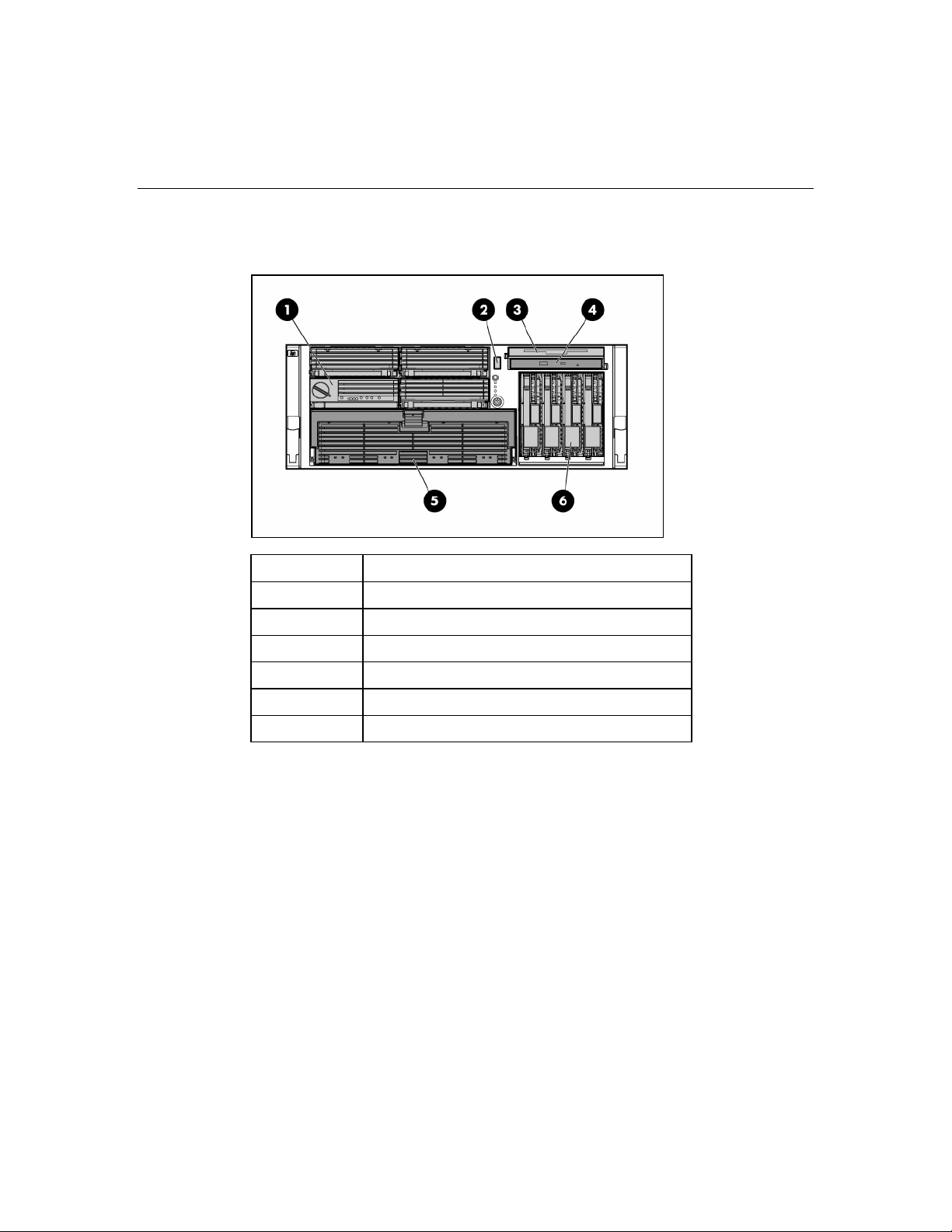
Front panel components
Item Description
1 Memory board or blank
2 USB port
3 Optional multibay drive or blank
4 DVD drive
5 Processor module
6 Hard drive bay
Page 11
Server component identification 11
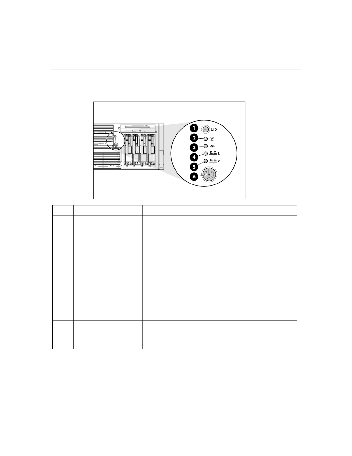
Front panel LEDs and buttons
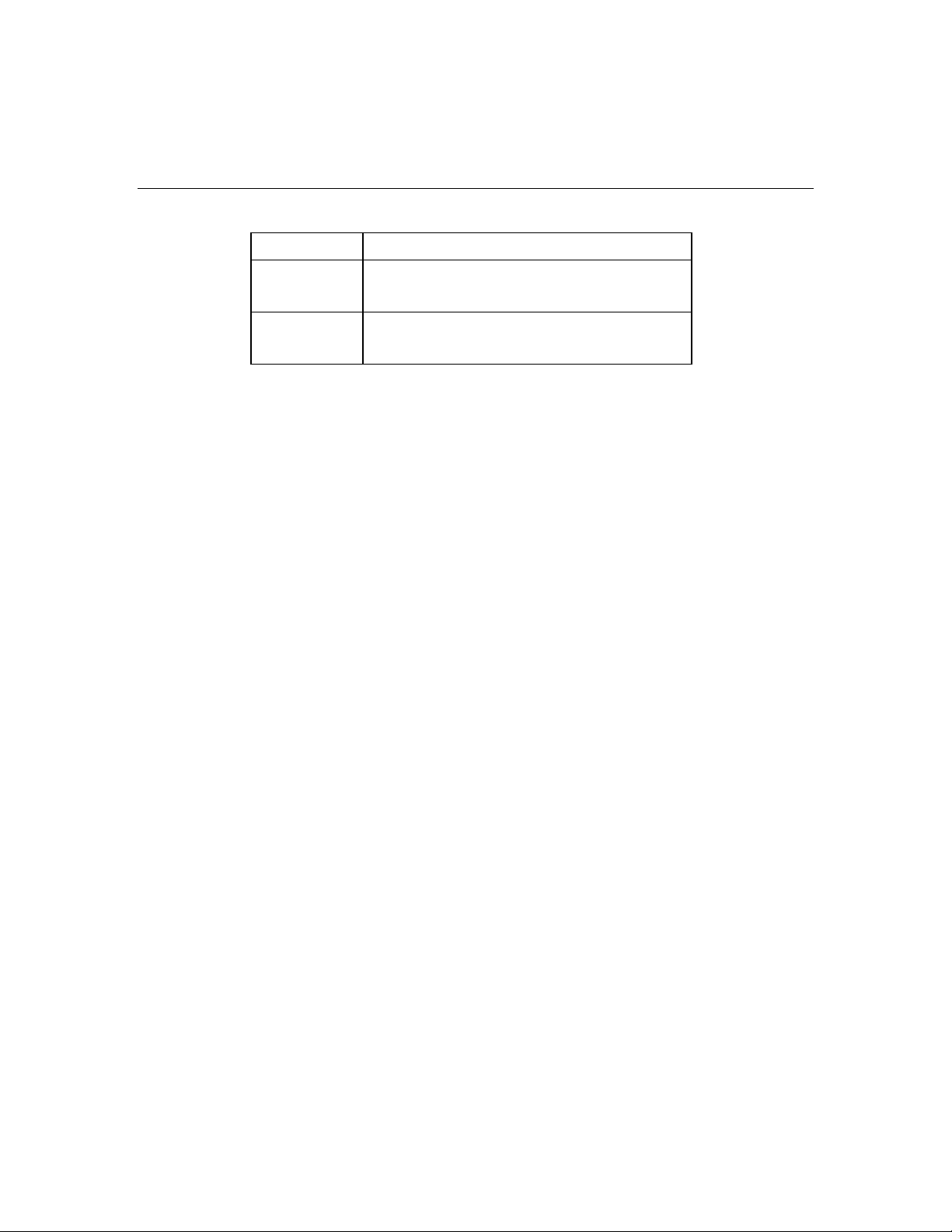
Item Description Status
1 UID switch and LED Blue = Activated
Flashing blue = Server being managed remotely
Off = Deactivated
2 Internal system health
LED
3 External system health
LED
4 NIC 1 link/activity LED Green = Linked to network
Green = Normal (system on)
Flashing amber = System health is degraded
Flashing red = System health is critical
Off = Normal (system off)
Green = Normal (system on)
Flashing amber = System health is degraded
Flashing red = System health is critical
Off = Normal (system off)
Flashing green = Linked with activity on the network
Off = No network connection
Page 12
12 HP ProLiant DL580 Generation 3 Server User Guide
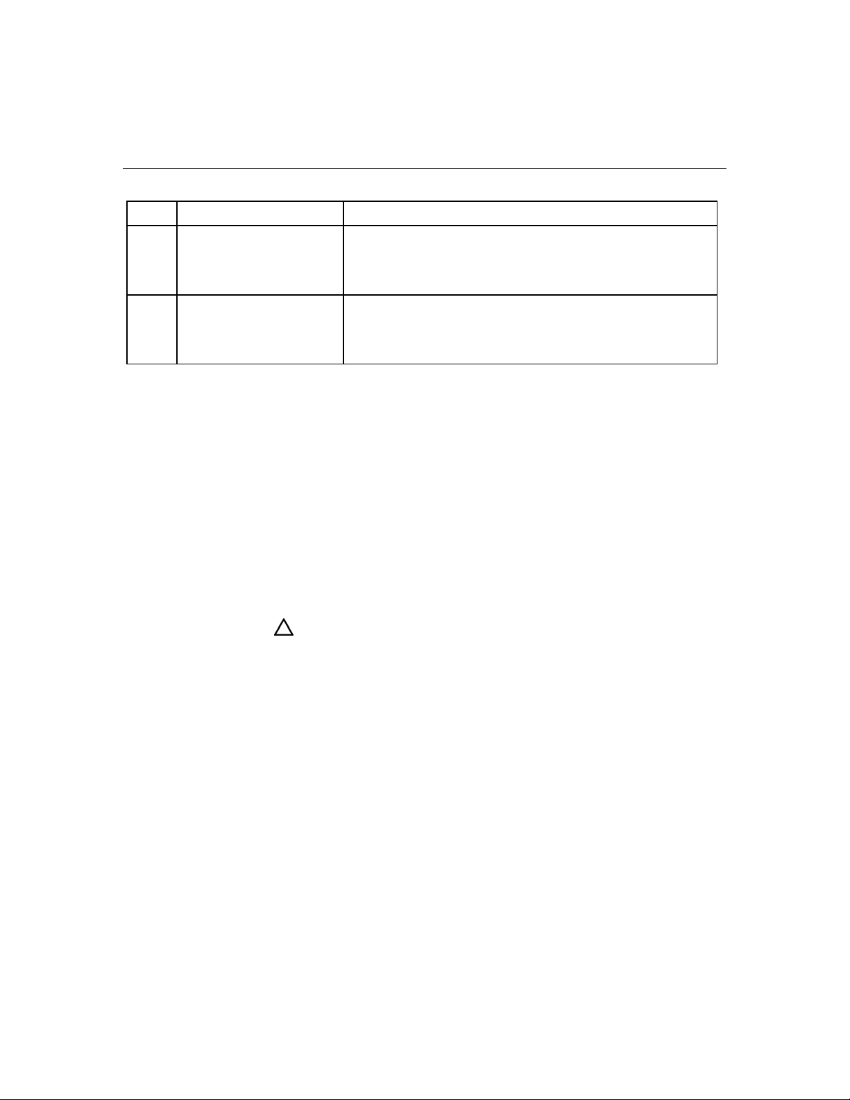
Item Description Status
5 NIC 2 link/activity LED Green = Linked to network
Flashing green = Linked with activity on the network
Off = No network connection
6 Power on/Standby button
and LED
Amber = System has AC power and is in standby mode
Green = System has AC power and is turned on
Off = System has no AC power
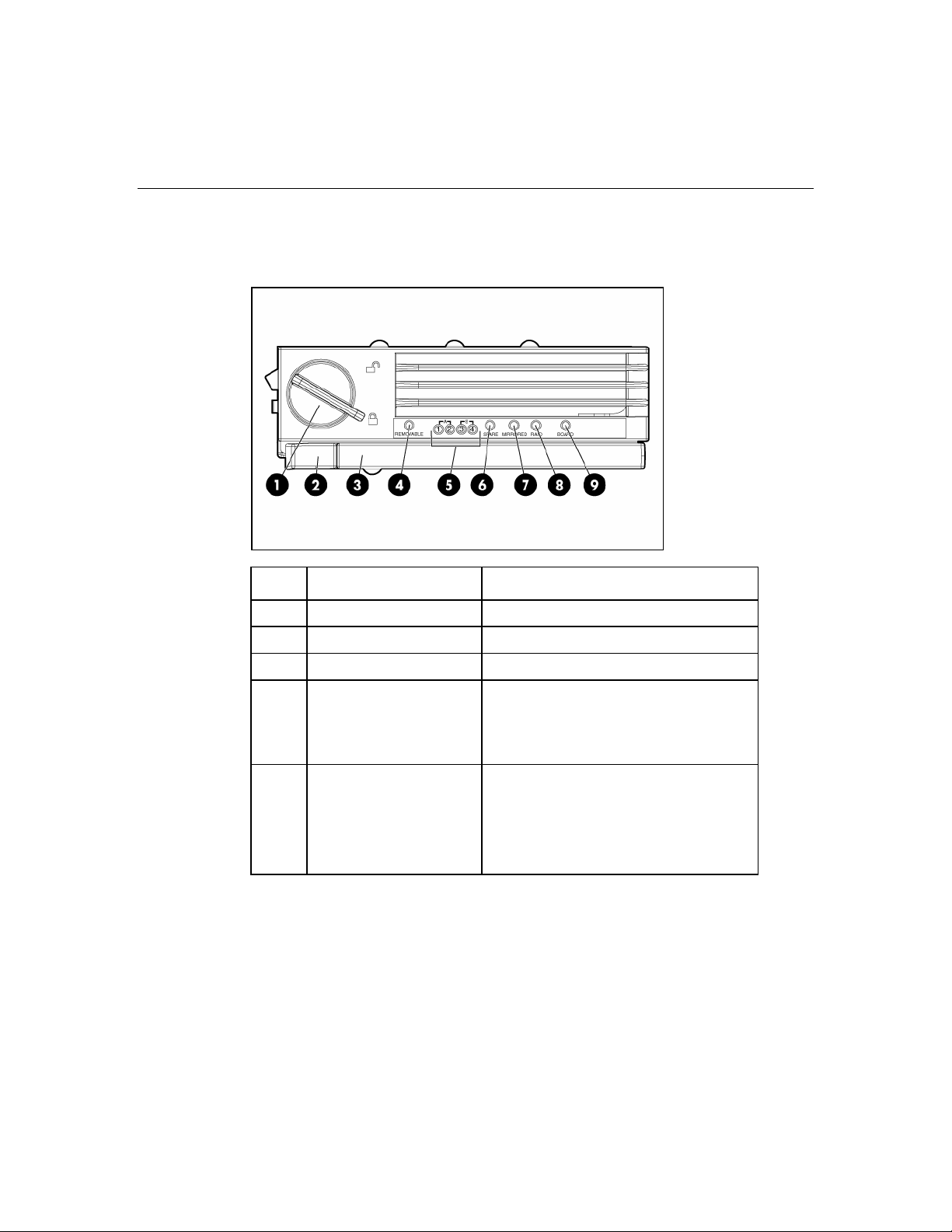
Memory board components and LEDs
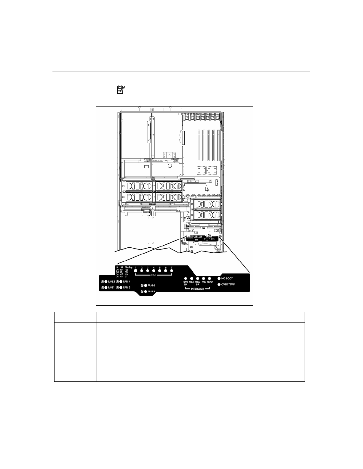
Error indicators remain illuminated when the system is powered off so that the
status of the LEDs can still be seen. This behavior matches the behavior of all the
other error indicators in the server.
The indicators are only cleared in the following situations:
• If the locking switch is locked after the board is reinstalled
• If the server is rebooted
• If the board is removed from the server
CAUTION: When the memory board locking switch is unlocked in
a mode that does not support hot-add or hot-replace capabilities, audio
alarms and visual alerts occur. Removing the memory board at this
point causes server failure.
To end the audio alarms and visual alerts, move the memory board
locking switch back to the locked position. This action does not result in
data corruption or server failure.
Page 13
Server component identification 13
If removal of a single memory board is required and it is the only
memory board, power down the server and make the necessary
memory changes.
Item Description Status
1 Locking switch N/A
2 Release latch N/A
3 Ejector lever N/A
4 Removable Off = Do not remove memory board if
server is powered on
Green = Memory board can be safely
removed
5 DIMM LEDs (1–4) Off = Normal or DIMM not installed
Amber = Uncorrectable error detected or
correctable error threshold reached
Flashing amber = DIMM configuration
error
Page 14

14 HP ProLiant DL580 Generation 3 Server User Guide
Item Description Status
6 Spare Off = Board not online or board not
configured for Online Spare Memory mode
Amber = Correctable error threshold
reached; server is in degraded Online
Spare Memory mode
Flashing amber = Memory configuration
error*
Green = Online Spare Memory mode
7 Mirrored Off = Board not online or board not
configured for Hot-Plug Mirrored Memory
mode
Amber = Server is in degraded Hot-Plug
Mirrored Memory mode
Flashing amber = Memory configuration
error*
Green = Hot-Plug Mirrored Memory mode
8 RAID Off = Board not online or board not
configured for Hot-Plug RAID Memory
mode
Amber = Server is in degraded Hot-Plug
RAID Memory mode
Flashing amber = Memory configuration
error*
Green = Hot-Plug RAID Memory mode
9 Board Off = Power off or locking switch unlocked
Amber = Memory error detected
Flashing amber = Memory configuration
error*
Flashing green = Board is rebuilding
Green = Normal
* AMP configuration errors occur when the current memory configuration is not
valid for the configured AMP mode:
Page 15

Server component identification 15
• If the mode selected is the desired mode, modify the DIMM or board
configuration to support the desired mode. For more information, refer to
"Memory Options (on page 95
)."
• If the mode selected is not the desired mode, run RBSU and change the AMP
mode. For more information, refer to the section "HP ROM-Based Setup
Utility (on page 125
NOTE: If the Spare, Mirrored, and RAID LEDs are off, the server is
in Advanced ECC mode. Refer to "HP ROM-Based Setup Utility (on
page 125
)" for more information.
)."
Processor module LEDs
PPM LED (1) Processor LED
(2)
Off Off Off One of the following conditions exist:
Off Amber Flashing amber Pre-failure error threshold exceeded; LEDs will
External health
LED
Description
• No AC power present
• Normal
clear after the next reboot
Page 16

16 HP ProLiant DL580 Generation 3 Server User Guide
PPM LED (1) Processor LED
(2)
External health
LED
Description
Off Amber Flashing red One or more of the following conditions exist:
• The processor was replaced and the LEDs
will clear after the next reboot
• Processor failed
Off Flashing amber Flashing red Processor configuration error detected
Amber Off Flashing red PPM failed
Flashing amber Off Flashing red One or more of the following conditions exist:
• PPM not installed
• PPM configuration error detected
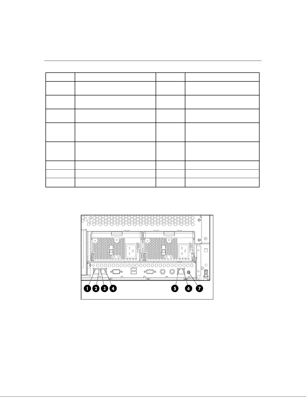
Rear panel components
Item Description Item Description
1 PCI-X non-hot-plug slot 7, 64-bit/100-
MHz
2 PCI-X non-hot-plug slot 6, 64-bit/100-
MHz
11 NIC port 2
12 NIC port 1
Page 17
Server component identification 17
Item Description Item Description
3 PCI-X non-hot-plug slot 5, 64-bit/133-
MHz
4 PCI-X non-hot-plug slot 4, 64-bit/133-
MHz
5 PCI-X non-hot-plug slot 3, 64-bit/133-
MHz
6 Optional PCI-X Hot Plug or optional
PCI Express non-hot-plug expansion
slot 2
7 Optional PCI-X Hot Plug or optional
PCI Express non-hot-plug expansion
slot 1
8 T-15 Torx screwdriver 18 iLO NIC
9 Optional power supply (redundant) 19 UID
10 Power supply (primary)
13 Serial port
14 USB ports
15 Video port
16 Keyboard port
17 Mouse port
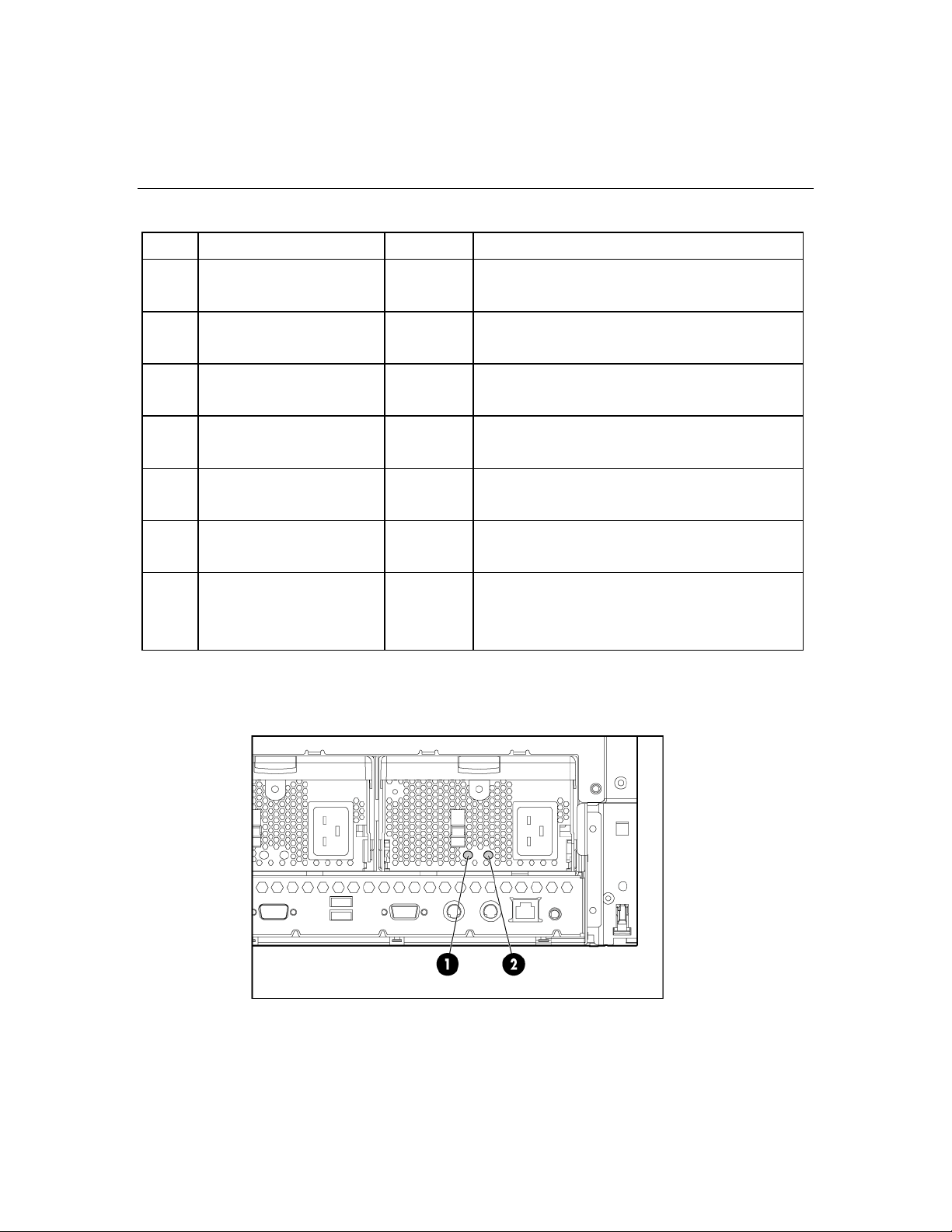
Rear panel LEDs and buttons
Page 18
18 HP ProLiant DL580 Generation 3 Server User Guide
Item Description LED color Status
1 NIC 1 Activity LED Green On or flashing = Network activity
Off = No network activity
2 NIC 1 Link LED Green On = Linked to network
Off = Not linked to network
3 NIC 2 Activity LED Green On or flashing = Network activity
Off = No network activity
4 NIC 2 Link LED Green On = Linked to network
Off = Not linked to network
5 iLO NIC Activity LED Green On or flashing = Network activity
Off = No network activity
6 iLO NIC Link LED Green On = Linked to network
Off = Not linked to network
7 UID LED Blue On = Activated
Flashing = Server remotely managed
Off = Deactivated
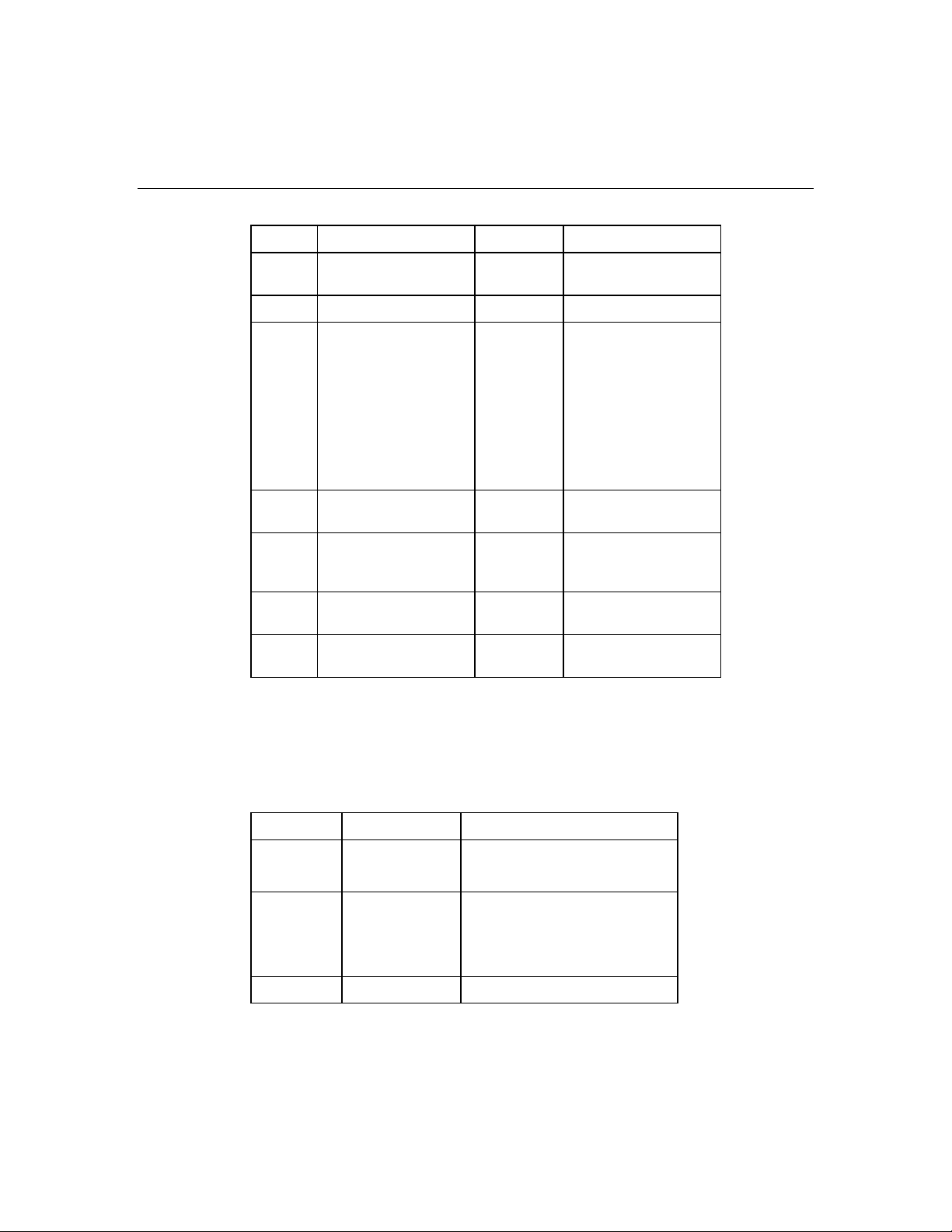
Power supply LEDs
Page 19

Server component identification 19
Fail LED 1
(amber)
Off Off No AC power to any power
Flashing Off Power supply failure (over
On Off No AC power to this power
Off Flashing • AC power present
Off On Normal
Power LED 2
(green)
Description
supply
current)
supply
• Standby mode
Page 20

20 HP ProLiant DL580 Generation 3 Server User Guide
System board components
Item Description Item Description
1 Fan 1 12 PCI-X, non-hot-plug
slot 7, 64-bit/100-MHz
2 Fan 2 13 BBWC battery pack
3 Fan 3 14 Remote management
connector
4 Fan 4 15 BBWC cache module
socket
Page 21
Server component identification 21
Item Description Item Description
5 System maintenance
16 Fan 6
switch
6 System battery 17 Fan 5
7 Connectors for one of
the following:
• PCI-X Hot Plug
18 Boot device selector
switch (default = FLP
TOP)
mezzanine option
• PCI Express x4
mezzanine option
• PCI Express x8
mezzanine option
8 PCI-X non-hot-plug
19 SCSI port A
slot 3, 64-bit/133-MHz
9 PCI-X, non-hot-plug
slot 4, 64-bit/133-MHz
20 SCSI simplex/duplex
switch (default =
duplex)
10 PCI-X, non-hot-plug
slot 5, 64-bit/133-MHz
11 PCI-X, non-hot-plug
21 QuickFind diagnostic
display
22 SCSI port B
slot 6, 64-bit/100-MHz
System maintenance switch
The system maintenance switch (SW1) is an eight-position switch that is used for
system configuration. The default position for all eight positions is Off.
Position Description Function
S1 iLO Security Off = iLO security is enabled
S2 Configuration
lock
S3 Reserved Reserved
On = iLO security is disabled
Off = System configuration can
be changed
On = System configuration is
locked
Page 22
22 HP ProLiant DL580 Generation 3 Server User Guide
Position Description Function
S4 Reserved Reserved
S5 Password
protection
override
S6 Invalidate
configuration
S7 Reserved Reserved
S8 Reserved Reserved
Boot device selector switch
The boot device selector switch setting determines the device access order of the
multibay drives in the server. The default setting for the boot device selector
switch is FLP TOP.
When the boot device selector switch is set to FLP TOP, the optical drive in the
bottom bay is designated as the primary optical drive. The diskette drive in the
top bay is bootable. The server cannot boot from a diskette drive in the bottom
bay when the boot device selector switch is set to FLP TOP.
Off = No function
On = Clears power-on
password and administrator
password
Off = Normal
On = Clears NVRAM
When the boot device selector switch is set to FLP BOT, the optical drive in the
top bay is designated as the primary optical drive. The diskette drive in the
bottom bay is bootable. The server cannot boot from a diskette drive in the top
bay when the boot device selector switch is set to FLP BOT.
NOTE: If two optical drives are installed in the server, the server
will first attempt to boot from the primary optical drive. The boot device
selector switch setting determines which drive is the primary optical
drive.
Page 23
Server component identification 23
Switch setting Description
FLP TOP
(default)
FLP BOT Primary optical drive in top bay is bootable
Diskette drive in top bay is bootable
Primary optical drive in bottom bay is bootable
Diskette drive in bottom bay is bootable
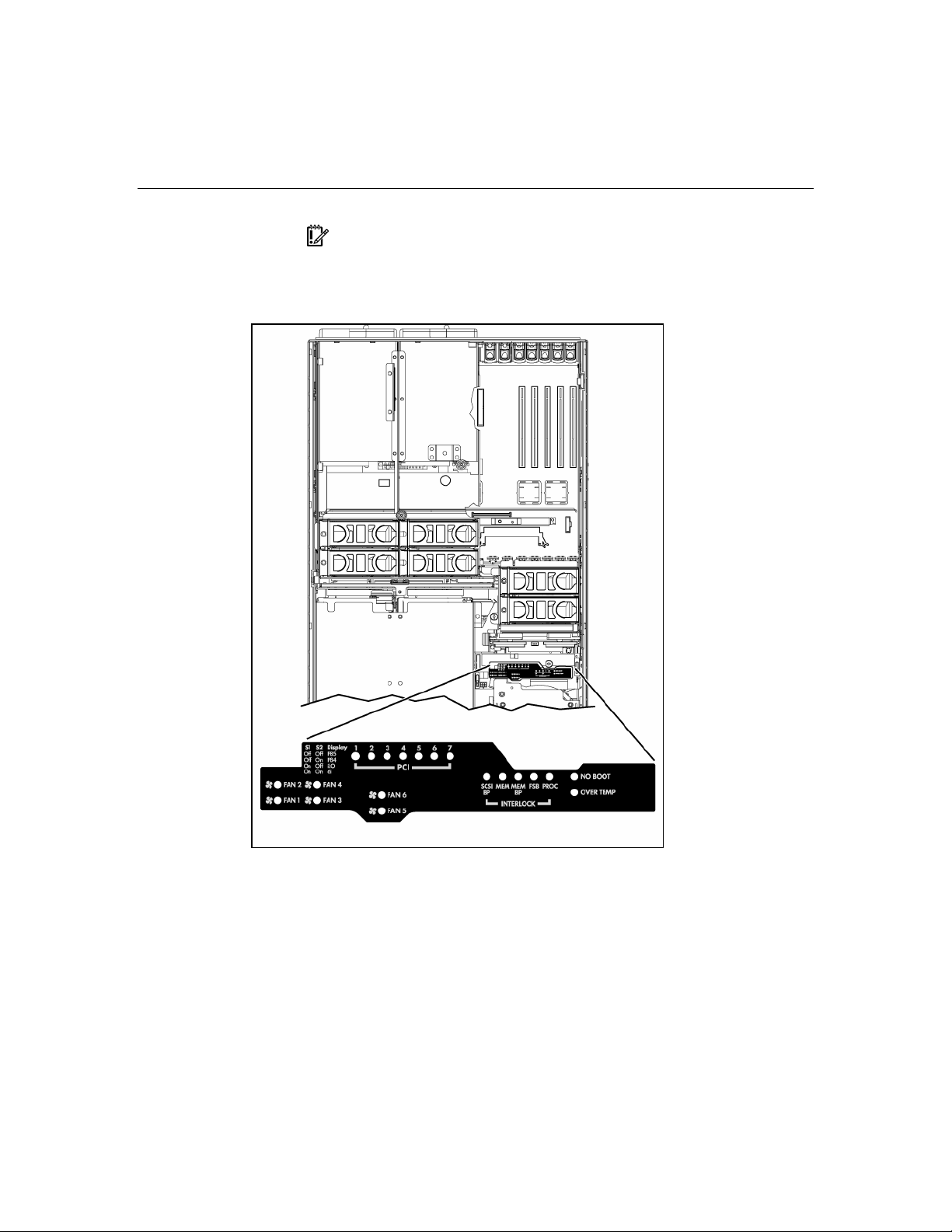
QuickFind diagnostic display LEDs
The front panel health LEDs indicate only the current hardware status. In some
situations, HP SIM might report server status differently than the health LEDs
because the software tracks more system attributes.
The amber QuickFind diagnostic display LEDs are located on the media board.
In normal operations, all of the LEDs are off unless one of the components fails.
Page 24
24 HP ProLiant DL580 Generation 3 Server User Guide
NOTE: The system management driver must be installed for the
internal health LED to provide pre-failure and warranty conditions.
LED Description
Fan X One or more of the following conditions exist:
• A fan is missing or not properly installed.
• A fan failed.
PCI X One or more of the following conditions exist:
• A PCI address parity error was detected on the numbered PCI slot.
• A PCI data parity error was detected on the numbered PCI slot.
Page 25
Server component identification 25
LED Description
SCSI BP The SCSI backplane is missing or not properly installed.
MEM A memory board is not properly installed.
MEM BP A memory backplane is missing or not properly installed.
FSB One or more of the following conditions exist:
• A processor or PPM is missing or not properly installed.
• An FSB configuration error was detected.
PROC A processor is missing or not properly installed.
OVER TEMP The internal temperature has exceeded operating levels.
NO BOOT A "no boot" condition was detected.
P84 Switch set to display port 84 codes.
P85 Switch set to display port 85 codes.
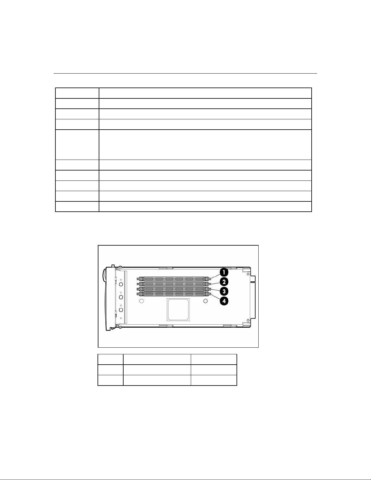
DIMM slot locations
Item Description Bank
1 DIMM slot 1 A
2 DIMM slot 2 A
Page 26
26 HP ProLiant DL580 Generation 3 Server User Guide
Item Description Bank
3 DIMM slot 3 B
4 DIMM slot 4 B
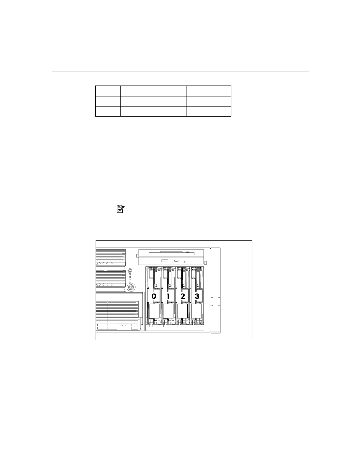
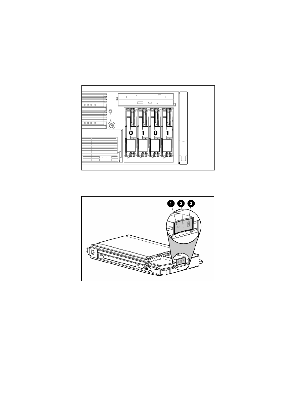
SCSI IDs
The server supports single- or dual-channel hard drive configurations. The
single-channel configuration (simplex mode) supports up to four hard drives on
one channel. The dual-channel configuration (duplex mode) supports two hard
drives on each channel (SCSI IDs 0 and 1).
The SCSI IDs for both simplex mode and duplex mode are illustrated. Always
populate hard drive bays starting with the lowest SCSI ID.
NOTE: These SCSI ID designations apply regardless of the
controller or the configuration used.
Simplex mode
Page 27
Server component identification 27
Duplex mode
Hot-plug SCSI hard drive LEDs
Page 28

28 HP ProLiant DL580 Generation 3 Server User Guide
Item LED description Status
1 Activity status On = Drive activity
Flashing = High activity on the drive or
drive is being configured as part of an
array.
Off = No drive activity
2 Online status On = Drive is part of an array and is
currently working.
Flashing = Drive is actively online.
Off = Drive is offline.
3 Fault status On = Drive failure
Flashing = Fault-process activity
Off = No fault-process activity
Hot-plug SCSI hard drive LED combinations
Activity
LED (1)
Online
LED (2)
Fault LED
(3)
Interpretation
On, off, or
On or off Flashing A predictive failure alert has been received for this drive.
flashing
On, off, or
On Off The drive is online and is configured as part of an array.
flashing
On or
Flashing Off
flashing
On Off Off
Replace the drive as soon as possible.
If the array is configured for fault tolerance and all other drives in
the array are online, and a predictive failure alert is received or a
drive capacity upgrade is in progress, you may replace the drive
online.
Do not remove the drive. Removing a drive may terminate the
current operation and cause data loss.
The drive is rebuilding or undergoing capacity expansion.
Do not remove the drive.
The drive is being accessed, but (1) it is not configured as part of an
array; (2) it is a replacement drive and rebuild has not yet started; or
(3) it is spinning up during the POST sequence.
Page 29
Server component identification 29
Activity
LED (1)
Flashing Flashing Flashing
Off Off On The drive has failed and has been placed offline.
Off Off Off Either (1) the drive is not configured as part of an array; (2) the
Online
LED (2)
Fault LED
(3)
Interpretation
Do not remove the drive. Removing a drive may cause data
loss in non-fault-tolerant configurations.
Either (1) the drive is part of an array being selected by an array
configuration utility; (2) Drive Identification has been selected in
HP SIM; or (3) drive firmware is being updated.
You may replace the drive.
drive is configured as part of an array, but it is a replacement drive
that is not being accessed or being rebuilt yet; or (3) the drive is
configured as an online spare.
If the drive is connected to an array controller, you may replace the
drive online.
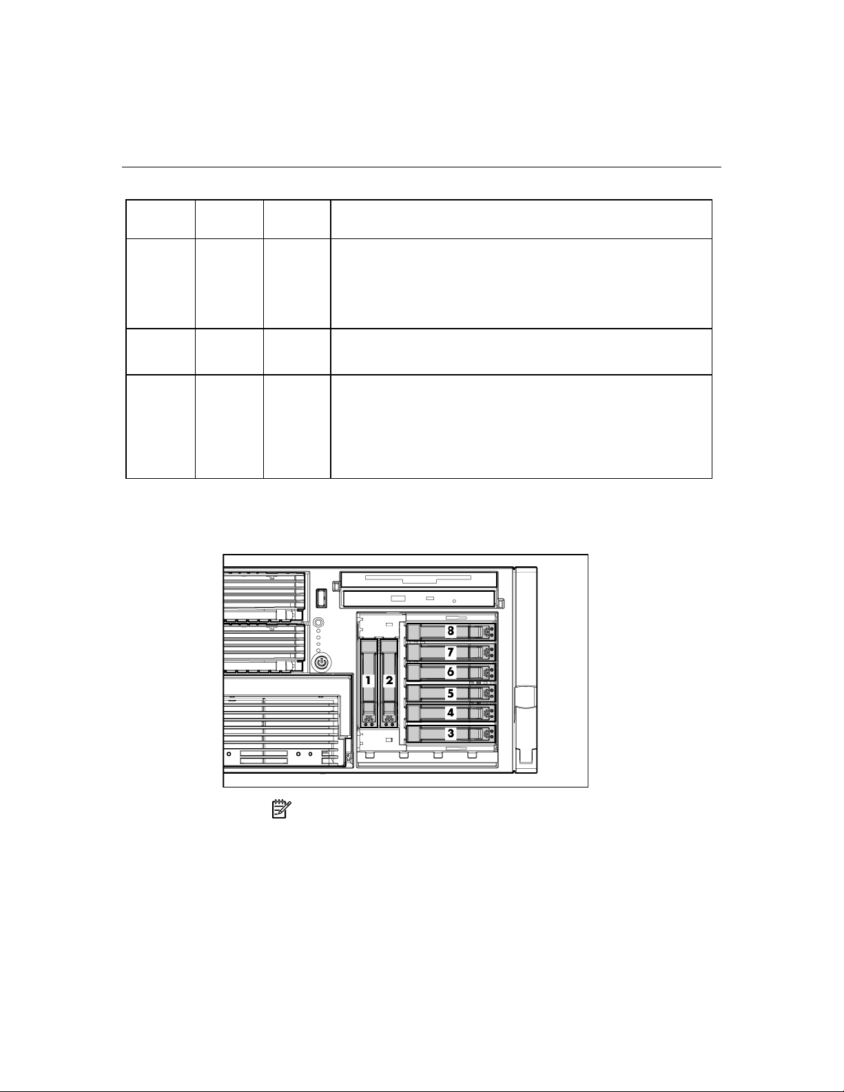
SATA or SAS IDs
NOTE: The server may look different from that shown.
When adding SAS hard drives to the server, observe the following general
guidelines:
Page 30
30 HP ProLiant DL580 Generation 3 Server User Guide
• The server supports eight SAS or SATA hot-plug hard drives.
• The system automatically sets all drive numbers.
• If only one hard drive is used, install it in the bay with the lowest number.
• Hard drives must be SFF types.
• Drives must be the same capacity to provide the greatest storage space
efficiency when drives are grouped together into the same drive array.
NOTE: ACU does not support mixing SAS and SATA drives in the
same logical volume.
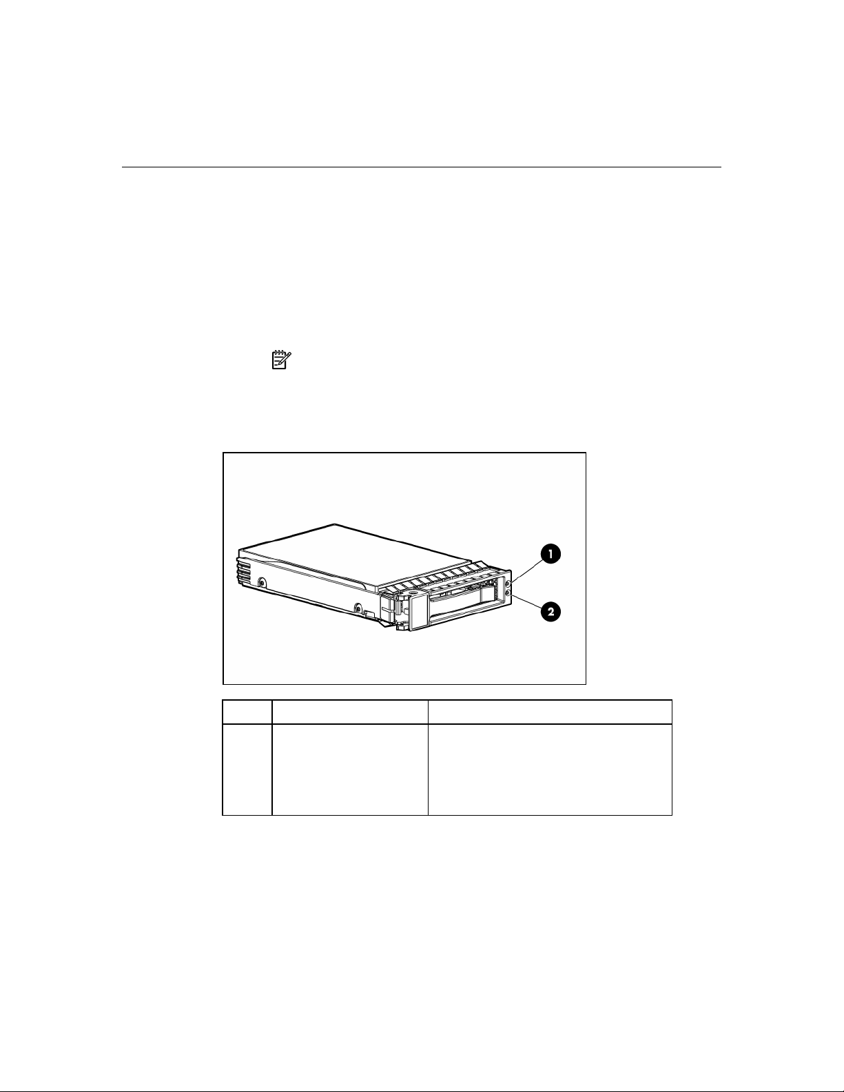
SATA or SAS hard drive LEDs
Item LED Description Status
1 Fault/UID status Amber = Drive failure
Flashing amber = Fault-process activity
Blue = Unit identification is active
Off = No fault-process activity
Page 31

Server component identification 31
Item LED Description Status
2 Online/Activity status Green = Drive activity
Flashing green = High activity on the
drive or drive is being configured as part
of an array
Off = No drive activity
SAS and SATA hard drive LED combinations
Online/Activity
LED (green)
Fault/UID LED
(amber/blue)
Interpretation
On, off, or
flashing
Alternating amber
and blue
The drive has failed, or a predictive failure alert has been
received for this drive; it also has been selected by a
management application.
On, off, or
flashing
On Amber, flashing
Steadily blue The drive is operating normally, and it has been selected by a
management application.
A predictive failure alert has been received for this drive.
regularly (1 Hz)
Replace the drive as soon as possible.
On Off The drive is online, but it is not active currently.
Flashing
regularly (1 Hz)
Amber, flashing
regularly (1 Hz)
Do not remove the drive. Removing a drive may terminate
the current operation and cause data loss.
The drive is part of an array that is undergoing capacity
expansion or stripe migration, but a predictive failure alert has
been received for this drive. To minimize the risk of data loss,
do not replace the drive until the expansion or migration is
complete.
Flashing
regularly (1 Hz)
Off
Do not remove the drive. Removing a drive may terminate
the current operation and cause data loss.
The drive is rebuilding, or it is part of an array that is
undergoing capacity expansion or stripe migration.
Flashing
irregularly
Flashing
Amber, flashing
regularly (1 Hz)
The drive is active, but a predictive failure alert has been
received for this drive. Replace the drive as soon as possible.
Off The drive is active, and it is operating normally.
irregularly
Page 32

32 HP ProLiant DL580 Generation 3 Server User Guide
Online/Activity
LED (green)
Off Steadily amber A critical fault condition has been identified for this drive, and
Off Amber, flashing
Off Off The drive is offline, a spare, or not configured as part of an
Fault/UID LED
(amber/blue)
regularly (1 Hz)
Interpretation
the controller has placed it offline. Replace the drive as soon
as possible.
A predictive failure alert has been received for this drive.
Replace the drive as soon as possible.
array.
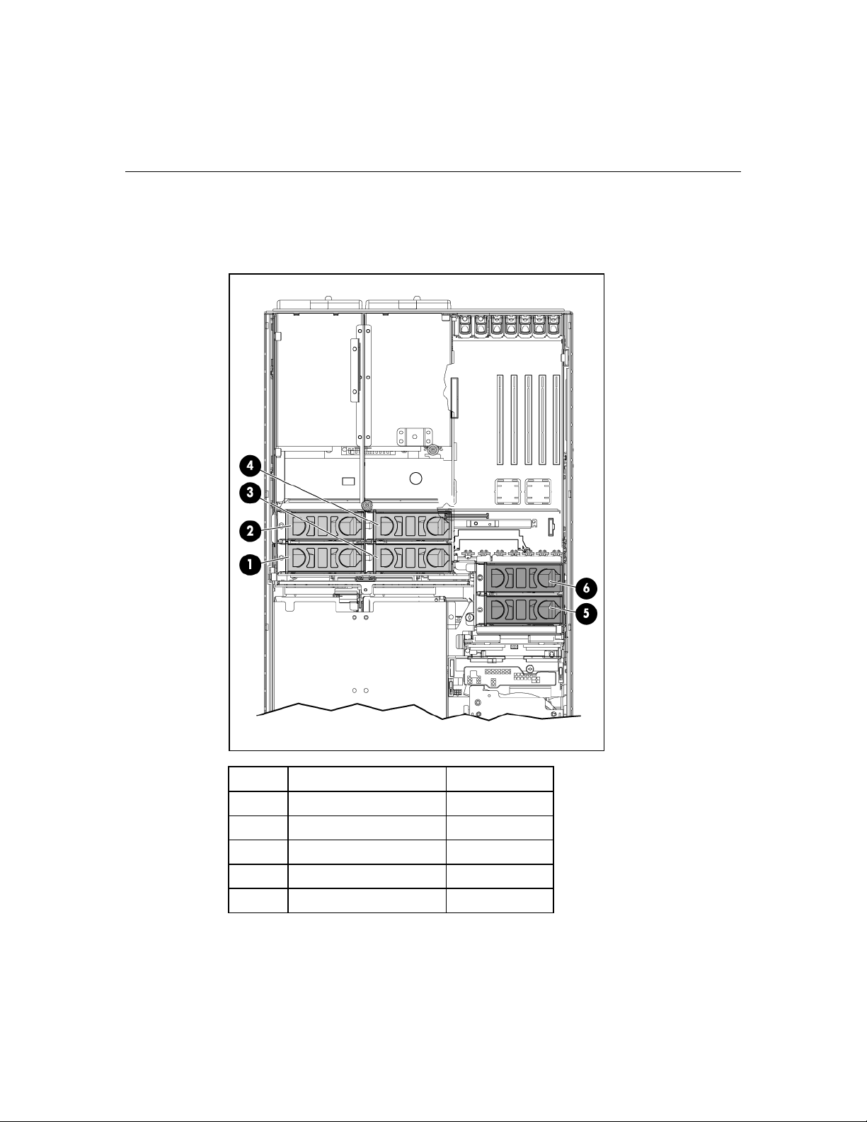
Fan locations
The server is shipped with six system fans. Each fan is hot-swappable and
independently controlled. The fans are distributed into two zones to control
thermal conditions within the server.
• Zone 1 contains four fans (three, plus one redundant) to control the
temperature in the processor module area.
• Zone 2 contains two fans (one, plus one redundant) to control the
temperature in the hard drive bay area.
Page 33
Server component identification 33
This fan configuration allows the server to continue operating in non-redundant
mode if a single fan fails in either zone. If the system detects two fan failures in
the same zone, the server shuts down to avoid thermal damage.
Item Description Zone
1 Fan 1 1
2 Fan 2 1
3 Fan 3 1
4 Fan 4 1
5 Fan 5 2
Page 34

34 HP ProLiant DL580 Generation 3 Server User Guide
Item Description Zone
6 Fan 6 2
Hot-plug fan LEDs
Status
Green = Operating normally
Amber = Failed
Off = No power
Page 35

Server component identification 35
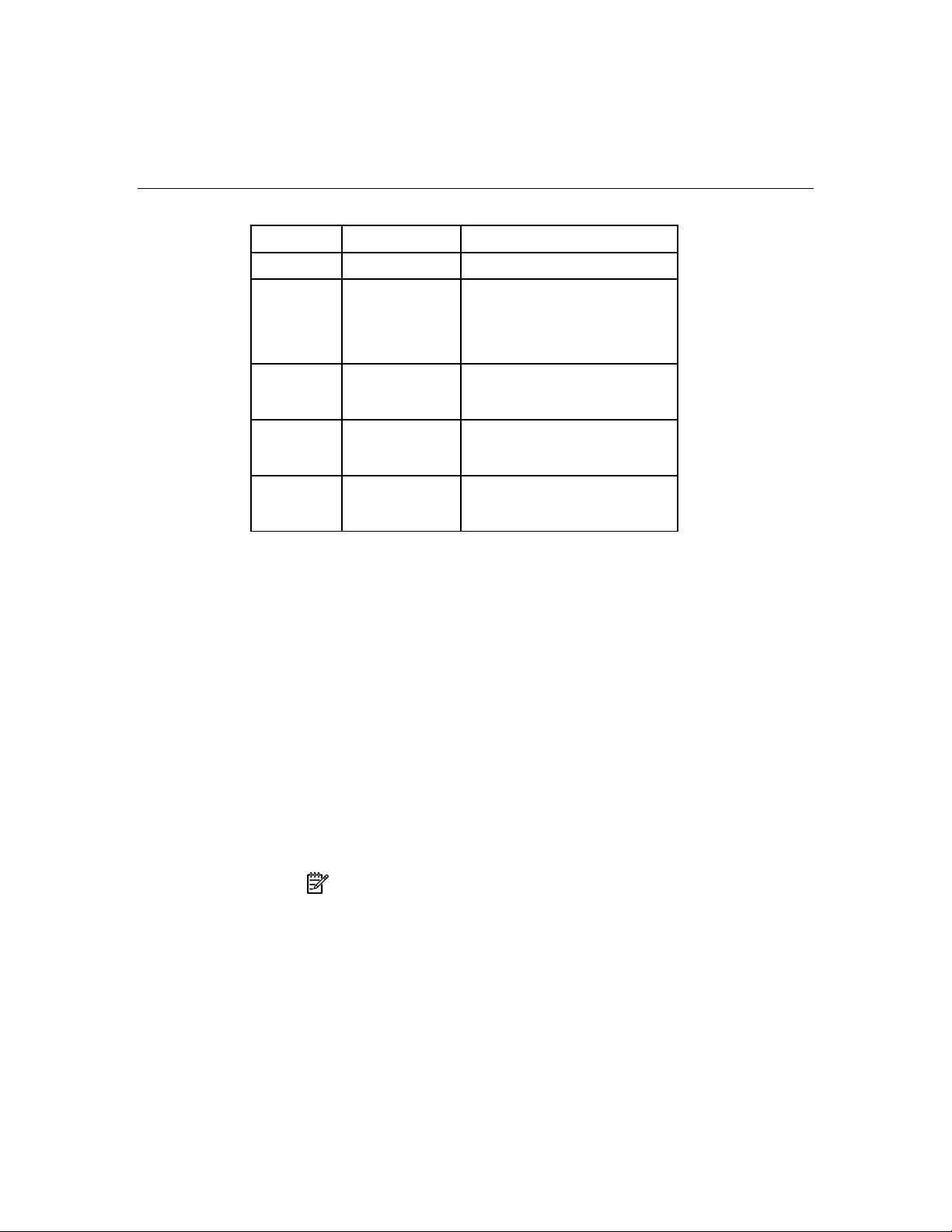
BBWC LEDs
Server status LED 1 (amber) LED 2 (green) Battery module status
Server is on and has
normal run time
Server is off and is in
data retention mode
Off On Fast charging
Off Flashing The microcontroller is waiting for
communication from the host controller.
Off Off The battery is fully charged.
On Off A short exists in the connection of one or
more of the three button cells within the
battery module.
Flashing Off An opening exists in the circuit between the
positive and negative terminals of the
battery module.
Off Off Normal
Flashing every
15 seconds
Off User data held in the write cache is being
backed up.
Page 36

Page 37

37
Server operations
In this section
Powering up the server .................................................................................................................37
Powering down the server ............................................................................................................37
Extending the server from the rack...............................................................................................38
Removing the access panel...........................................................................................................40
Replacing hot-plug fans................................................................................................................41
Removing the system cage ...........................................................................................................42
Accessing the QuickFind diagnostic display................................................................................43
Battery ..........................................................................................................................................44
Powering up the server
To power up the server, press the Power On/Standby button.
Powering down the server
WARNING: To reduce the risk of personal injury, electric
shock, or damage to the equipment, remove the power cord to
remove power from the server. The front panel Power On/Standby
button does not completely shut off system power. Portions of the
power supply and some internal circuitry remain active until AC
power is removed.
IMPORTANT: If installing a hot-plug device, it is not necessary to
power down the server.
1. Shut down the OS as directed by the OS documentation.
2. Press the Power On/Standby button to place the server in standby mode.
When the server enters standby power mode, the system power LED changes
to amber.
3. Disconnect the power cords.
The system is now without power.
Page 38

38 HP ProLiant DL580 Generation 3 Server User Guide
Extending the server from the rack
The design of the server enables you to access several components through the
front of the server. Installing or accessing the following components will not
require extending the server from the rack:
• Processors
• Memory boards
• DIMMs
• DVD drive
• Diskette drive
• Hard drives
To extend the server from the rack:
1. Release the two levers on the lower outside corners of the rack.
NOTE: If the server is in a rack and in the shipping configuration,
remove the two shipping screws directly behind the levers.
IMPORTANT: If the server is installed in a telco rack, remove the
server from the rack to access internal components.
Page 39

Server operations 39
2. Extend the server on the rack rails until the server rail-release latches engage.
WARNING: To reduce the risk of personal injury or equipment
damage, be sure that the rack is adequately stabilized before
extending a component from the rack.
WARNING: To reduce the risk of personal injury, be careful
when pressing the server rail-release latches and sliding the server
into the rack. The sliding rails could pinch your fingers.
3. After performing the installation or maintenance procedure, slide the server
back into the rack by pressing the server rail-release latches.
Page 40

40 HP ProLiant DL580 Generation 3 Server User Guide
NOTE: The release latches will lock into place when the rails are
fully extended.
Removing the access panel
WARNING: To reduce the risk of personal injury from hot
surfaces, allow the drives and the internal system components to
cool before touching them.
CAUTION: Do not operate the server for long periods with the
access panel open or removed. Operating the server in this manner
results in improper airflow and improper cooling that can lead to thermal
damage.
IMPORTANT: When removing the access panel to view QuickFind
diagnostic LEDs, leave the server powered on. The QuickFind
diagnostic LEDs are cleared when the server is powered off.
1. Extend the server from the rack, if applicable ("Extending the server from the
rack" on page 38
2. If the locking latch is locked, use a Torx T-15 screwdriver to unlock the
latch.
NOTE: The T-15 Torx screwdriver is shipped with the server and
can be located on the rear panel ("Rear panel components" on page
16
).
).
Page 41

Server operations 41
3. Lift up on the hood latch, and remove the access panel.
4. After installing hardware options, replace the access panel. Be sure that the
panel is securely locked into place before powering up the server.
Replacing hot-plug fans
The server supports redundant hot-plug fans ("Fan locations" on page 32) to
provide proper airflow to the server if a primary fan fails.
WARNING: To prevent personal injury from hazardous
energy:
• Remove watches, rings, or other metal objects.
• Use tools with insulated handles.
• Do not place tools or metal parts on top of batteries.
IMPORTANT: Remove and replace one fan at a time. If the
system detects two fan failures in the same zone, the server shuts down
to avoid thermal damage.
1. Extend the server from the rack, if applicable ("Extending the server from the
rack" on page 38
2. Remove the access panel ("Removing the access panel" on page 40
).
).
3. Remove the malfunctioning hot-plug fan from the server.
Page 42

42 HP ProLiant DL580 Generation 3 Server User Guide
4. Install the replacement fan.
5. Repeat to replace additional fans as needed.
6. Observe the LED on each installed fan to be sure it is illuminated green
("Hot-plug fan LEDs" on page 34
).
7. Observe the internal system health LED on the front panel to be sure it is
illuminated green ("Front panel LEDs and buttons" on page 11
).
NOTE: If the front panel internal system health LED is not green
after you install hot-plug fans, reseat the hot-plug fan or refer to the
troubleshooting section.
Removing the system cage
Installing or accessing some options in the server may require removing the
system cage. Refer to the instructions for each individual option to determine if
removing the system cage is necessary.
To remove the system cage:
1. Power down the server, if applicable ("Powering down the server" on page
37
).
2. Extend the server from the rack, if applicable ("Extending the server from the
rack" on page 38
).
Page 43

Server operations 43
3. Remove the access panel ("Removing the access panel" on page 40).
4. Remove all expansion boards and expansion slot covers.
5. Remove the PCI-X Hot Plug basket, if applicable.
6. Disconnect the hot-plug board cable from the PCI-X Hot Plug mezzanine
board, if applicable.
7. Remove all system fans ("Replacing hot-plug fans" on page 41
).
8. Remove all power supplies ("Redundant hot-plug power supply" on page
).
71
9. Loosen the thumbscrews, and lift the system cage from the server.
NOTE: The T-15 Torx screwdriver can be used to loosen the
thumbscrews. The T-15 Torx screwdriver is shipped with the server and
can be located on the rear panel ("Rear panel components" on page
16
).
Accessing the QuickFind diagnostic display
1. Extend the server from the rack, if applicable ("Extending the server from the
rack" on page 38
2. Remove the access panel ("Removing the access panel" on page 40
).
).
Page 44
44 HP ProLiant DL580 Generation 3 Server User Guide
IMPORTANT: When removing the access panel to view QuickFind
diagnostic LEDs, leave the server powered on. The QuickFind
diagnostic LEDs are cleared when the server is powered off.
3. Locate the QuickFind diagnostic display.
Battery
If the server no longer automatically displays the correct date and time, you may
need to replace the battery that provides power to the real-time clock. Under
normal use, battery life is 5 to 10 years.
Page 45

Server operations 45
WARNING: The computer contains an internal lithium
manganese dioxide, a vanadium pentoxide, or an alkaline battery
pack. A risk of fire and burns exists if the battery pack is not
properly handled. To reduce the risk of personal injury:
• Do not attempt to recharge the battery.
• Do not expose the battery to temperatures higher than
60°C (140°F).
• Do not disassemble, crush, puncture, short external contacts,
or dispose of in fire or water.
• Replace only with the spare designated for this product.
To remove the component:
1. Power down the server ("Powering down the server" on page 37
).
2. Extend the server from the rack, if applicable ("Extending the server from the
rack" on page 38
3. Remove the access panel ("Removing the access panel" on page 40
).
).
4. Remove any hardware that will interfere with accessing the battery.
5. Remove the battery.
To replace the component, reverse the removal procedure.
For more information about battery replacement or proper disposal, contact an
authorized reseller or an authorized service provider.
Page 46

Page 47

47
Server setup
In this section
Optional installation services........................................................................................................47
Rack planning resources...............................................................................................................48
Optimum environment..................................................................................................................49
Rack warnings and cautions .........................................................................................................52
Identifying rack server shipping carton contents..........................................................................54
Installing hardware options ..........................................................................................................54
Installing the server into the rack .................................................................................................54
Installing the cable management arm ...........................................................................................55
Powering up and configuring the server.......................................................................................55
Installing the operating system.....................................................................................................55
Registering the server ...................................................................................................................56
Optional installation services
Delivered by experienced, certified engineers, HP Care Pack services help you
keep your servers up and running with support packages tailored specifically for
HP ProLiant systems. HP Care Packs let you integrate both hardware and
software support into a single package. A number of service level options are
available to meet your needs.
HP Care Pack Services offer upgraded service levels to expand your standard
product warranty with easy-to-buy, easy-to-use support packages that help you
make the most of your server investments. Some of the Care Pack services are:
• Hardware support
– 6-Hour Call-to-Repair
– 4-Hour 24x7 Same Day
– 4-Hour Same Business Day
• Software support
– Microsoft®
Page 48

48 HP ProLiant DL580 Generation 3 Server User Guide
– Linux
– HP ProLiant Essentials (HP SIM and RDP)
– VMWare
• Integrated hardware and software support
– Critical Service
– Proactive 24
– Support Plus
– Support Plus 24
• Startup and implementation services for both hardware and software
For more information on Care Packs, refer to the HP website
(http://www.hp.com/hps/carepack/servers/cp_proliant.html
Rack planning resources
The rack resource kit ships with all HP branded or Compaq branded 9000,
10000, and H9 series racks. A summary of the content of each resource follows:
).
• Custom Builder is a web-based service for configuring one or many racks.
Rack configurations can be created using:
– A simple, guided interface
– Build-it-yourself mode
For more information, refer to the HP website
(http://www.hp.com/products/configurator
).
• The Installing Rack Products video provides a visual overview of operations
required for configuring a rack with rack-mountable components. It also
provides the following important configuration steps:
– Planning the site
– Installing rack servers and rack options
– Cabling servers in a rack
– Coupling multiple racks
Page 49

Server setup 49
• The Rack Products Documentation CD enables you to view, search, and print
documentation for HP and Compaq branded racks and rack options. It also
helps you set up and optimize a rack in a manner that best fits your
environment.
If you intend to deploy and configure multiple servers in a single rack, refer to
the white paper on high-density deployment on the HP website
(http://www.hp.com/products/servers/platforms
).
Optimum environment
When installing the server, select a location that meets the environmental
standards described in this section.
Space and airflow requirements
To allow for servicing and adequate airflow, observe the following space and
airflow requirements when deciding where to install a rack:
• Leave a minimum clearance of 122 cm (48 in) in front of the rack.
• Leave a minimum clearance of 76.2 cm (30 in) behind the rack.
• Leave a minimum clearance of 122 cm (48 in) from the back of the rack to
the back of another rack when racks are back-to-back.
HP servers draw in cool air through the front door and expel warm air through
the rear door. Therefore, the front and rear rack doors must be adequately
ventilated to allow ambient room air to enter the cabinet, and the rear door must
be adequately ventilated to allow the warm air to escape from the cabinet.
CAUTION: To prevent improper cooling and damage to the
equipment, do not block the ventilation openings.
When vertical space in the rack is not filled by a server or rack component, the
gaps between the components cause changes in airflow through the rack and
across the servers. Cover all gaps with blanking panels to maintain proper
airflow.
Page 50

50 HP ProLiant DL580 Generation 3 Server User Guide
CAUTION: Always use blanking panels to fill empty vertical
spaces in the rack. This arrangement ensures proper airflow. Using a
rack without blanking panels results in improper cooling that can lead to
thermal damage.
The Compaq 9000 and 10000 Series racks provide proper server cooling from
flow-through perforations in the front and rear doors that provide 64 percent
open area for ventilation.
CAUTION: When using a Compaq branded 7000 Series rack, you
must install the high airflow rack door insert [P/N 327281-B21 (42U) or
P/N 157847-B21 (22U)] to provide proper front-to-back airflow and
cooling.
CAUTION: If a third-party rack is used, observe the following
additional requirements to ensure adequate airflow and to prevent
damage to the equipment:
• Front and rear doors—If the 42U rack includes closing front and rear
doors, you must allow 5,350 sq cm (830 sq in) of holes evenly
distributed from top to bottom to permit adequate airflow (equivalent
to the required 64 percent open area for ventilation).
• Side—The clearance between the installed rack component and the
side panels of the rack must be a minimum of 7 cm (2.75 in).
Temperature requirements
To ensure continued safe and reliable equipment operation, install or position the
system in a well-ventilated, climate-controlled environment.
The maximum recommended ambient operating temperature (TMRA) for most
server products is 35°C (95°F). The temperature in the room where the rack is
located must not exceed 35°C (95°F).
CAUTION: To reduce the risk of damage to the equipment when
installing third-party options:
• Do not permit optional equipment to impede airflow around the
server or to increase the internal rack temperature beyond the
maximum allowable limits.
• Do not exceed the manufacturer’s TMRA.
Page 51

Server setup 51
Power requirements
Installation of this equipment must comply with local and regional electrical
regulations governing the installation of information technology equipment by
licensed electricians. This equipment is designed to operate in installations
covered by NFPA 70, 1999 Edition (National Electric Code) and NFPA-75, 1992
(code for Protection of Electronic Computer/Data Processing Equipment). For
electrical power ratings on options, refer to the product rating label or the user
documentation supplied with that option.
WARNING: To reduce the risk of personal injury, fire, or
damage to the equipment, do not overload the AC supply branch
circuit that provides power to the rack. Consult the electrical
authority having jurisdiction over wiring and installation
requirements of your facility.
CAUTION: Protect the server from power fluctuations and
temporary interruptions with a regulating uninterruptible power supply
(UPS). This device protects the hardware from damage caused by
power surges and voltage spikes and keeps the system in operation
during a power failure.
When installing more than one server, you may need to use additional power
distribution devices to safely provide power to all devices. Observe the following
guidelines:
• Balance the server power load between available AC supply branch circuits.
• Do not allow the overall system AC current load to exceed 80 percent of the
branch circuit AC current rating.
• Do not use common power outlet strips for this equipment.
• Provide a separate electrical circuit for the server.
Page 52

52 HP ProLiant DL580 Generation 3 Server User Guide
Electrical grounding requirements
The server must be grounded properly for proper operation and safety. In the
United States, you must install the equipment in accordance with NFPA 70, 1999
Edition (National Electric Code), Article 250, as well as any local and regional
building codes. In Canada, you must install the equipment in accordance with
Canadian Standards Association, CSA C22.1, Canadian Electrical Code. In all
other countries, you must install the equipment in accordance with any regional
or national electrical wiring codes, such as the International Electrotechnical
Commission (IEC) Code 364, parts 1 through 7. Furthermore, you must be sure
that all power distribution devices used in the installation, such as branch wiring
and receptacles, are listed or certified grounding-type devices.
Because of the high ground-leakage currents associated with multiple servers
connected to the same power source, HP recommends the use of a PDU that is
either permanently wired to the building’s branch circuit or includes a
nondetachable cord that is wired to an industrial-style plug. NEMA locking-style
plugs or those complying with IEC 60309 are considered suitable for this
purpose. Using common power outlet strips for the server is not recommended.
Rack warnings and cautions
WARNING: To reduce the risk of personal injury or damage to
the equipment, be sure that:
• The leveling jacks are extended to the floor.
• The full weight of the rack rests on the leveling jacks.
• The stabilizing feet are attached to the rack if it is a single-rack
installation.
• The racks are coupled together in multiple-rack installations.
• Only one component is extended at a time. A rack may become
unstable if more than one component is extended for any
reason.
WARNING: To reduce the risk of personal injury or equipment
damage when unloading a rack:
Page 53

Server setup 53
• At least two people are needed to safely unload the rack from
the pallet. An empty 42U rack can weigh as much as 115 kg
(253 lb), can stand more than 2.1 m (7 ft) tall, and may become
unstable when being moved on its casters.
• Never stand in front of the rack when it is rolling down the ramp
from the pallet. Always handle the rack from both sides.
WARNING: When installing a server in a telco rack, be sure
that the rack frame is adequately secured to the top and bottom of
the building structure.
WARNING: This server is very heavy. To reduce the risk of
personal injury or damage to the equipment:
• Observe local occupational health and safety requirements and
guidelines for manual material handling.
• Get help to lift and stabilize the product during installation or
removal, especially when the product is not fastened to the
rails. When the server weighs more than 22.5 kg (50 lb), at least
two people must lift the server into the rack together. A third
person may be required to help align the server if the server is
installed higher than chest level.
• Use caution when installing the server in or removing the
server from the rack; it is unstable when not fastened to the
rails.
WARNING: To reduce the risk of personal injury from hot
surfaces, allow the drives and the internal system components to
cool before touching them.
WARNING: To reduce the risk of personal injury, electric
shock, or damage to the equipment, remove the power cord to
remove power from the server. The front panel Power On/Standby
button does not completely shut off system power. Portions of the
power supply and some internal circuitry remain active until AC
power is removed.
CAUTION: Protect the server from power fluctuations and
temporary interruptions with a regulating uninterruptible power supply
(UPS). This device protects the hardware from damage caused by
power surges and voltage spikes and keeps the system in operation
during a power failure.
Page 54

54 HP ProLiant DL580 Generation 3 Server User Guide
CAUTION: Do not operate the server for long periods with the
access panel open or removed. Operating the server in this manner
results in improper airflow and improper cooling that can lead to thermal
damage.
Identifying rack server shipping carton contents
Unpack the server shipping carton and locate the materials and documentation
necessary for installing the server. All the rack mounting hardware necessary for
installing the server into the rack is included with the rack or the server.
The contents of the server shipping carton include:
• Server
• Power cord
• Hardware documentation, Documentation CD, and software products
• Rack mounting hardware
In addition to the supplied items, you may need:
• Hardware options
• Operating system or application software
• PDU
Installing hardware options
Install any hardware options before initializing the server. For options installation
information, refer to the option documentation. For server-specific information,
refer to "Hardware options installation (on page 57
Installing the server into the rack
Refer to the installation instructions that ship with the rack kit to install the server
into the rack.
)."
Page 55

Server setup 55
Installing the cable management arm
Refer to the installation instructions that ship with the rack kit to install the cable
management arm.
Powering up and configuring the server
To power up the server, press the Power On/Standby button.
While the server boots, RBSU is automatically configured to prepare the server
for OS installation.
To manually configure the utilities, press the F9 key when prompted during the
boot process to change the server settings using RBSU. The system is set up by
default for the English language.
NOTE: If an array controller has been added or is embedded in the
system, the ORCA utility provides a default RAID configuration based
on the size and number of hard drives installed.
For more information on the automatic configuration, refer to the HP ROM-
Based Setup Utility User Guide located on the Documentation CD.
Installing the operating system
To operate properly, the server must have a supported operating system. For the
latest information on supported operating systems, refer to the HP website
(http://www.hp.com/go/supportos
Two methods are available to install an operating system on the server:
• SmartStart assisted installation—Insert the SmartStart CD into the CD-ROM
drive and reboot the server.
• Manual installation—Insert the operating system CD into the CD-ROM drive
and reboot the server. This process may require you to obtain additional
drivers from the HP website (http://www.hp.com/support
Follow the on-screen instructions to begin the installation process.
).
).
Page 56

56 HP ProLiant DL580 Generation 3 Server User Guide
For information on using these installation paths, refer to the SmartStart
installation poster in the HP ProLiant Essentials Foundation Pack, included with
the server.
Registering the server
To register a server, refer to the registration card in the HP ProLiant Essentials
Foundation Pack or the HP Registration website (http://register.hp.com
).
Page 57

57
Hardware options installation
In this section
Introduction ..................................................................................................................................57
Processor options..........................................................................................................................57
Hot-plug SCSI hard drive options ................................................................................................63
SAS and SATA hard drive guidelines..........................................................................................66
Redundant hot-plug power supply................................................................................................71
Battery-Backed Write Cache........................................................................................................73
DVD, diskette, and CD-RW drives ..............................................................................................75
Introduction
If more than one option is being installed, read the installation instructions for all
the hardware options and identify similar steps to streamline the installation
process.
WARNING: To reduce the risk of personal injury from hot
surfaces, allow the drives and the internal system components to
cool before touching them.
CAUTION: To prevent damage to electrical components, properly
ground the server before beginning any installation procedure. Improper
grounding can cause electrostatic discharge.
Review "Electrostatic Discharge (on page 141)" before installing hardware
options into the server.
Processor options
The server supports up to four processors. Processor socket 1 and PPM slot 1
must be populated at all times or the server will not function properly.
Server PPMs provide the proper power to each processor. Each PPM must be
installed in the slot adjacent to its processor.
Page 58

58 HP ProLiant DL580 Generation 3 Server User Guide
Removing the Processor Module
The processors are stored in a module at the front of the server. Access to the
processor module is provided through the front panel, eliminating the need to
extend the server from the rack to install new or replace existing processors.
To remove the processor module:
1. Power down the server ("Powering down the server" on page 37
2. Release the latches to unlock the processor module.
).
Page 59
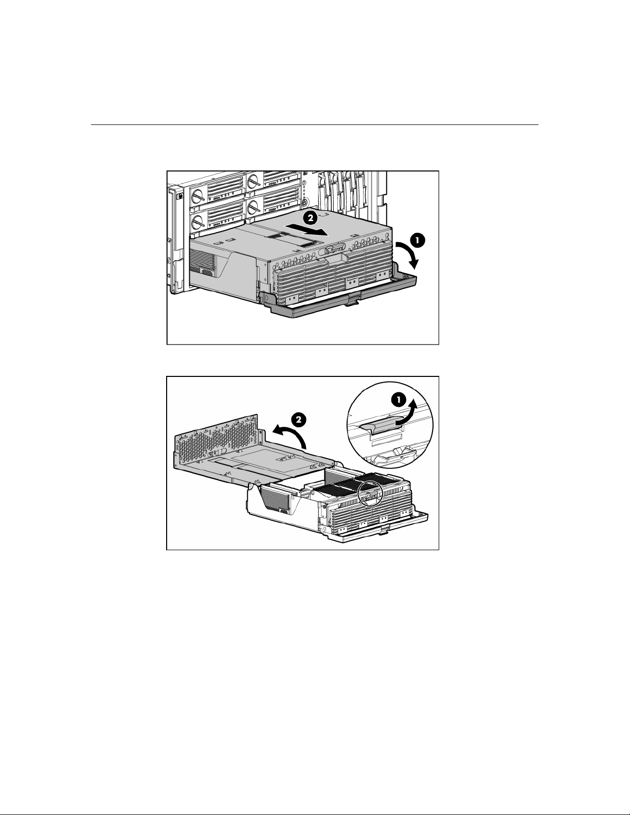
Hardware options installation 59
3. Lower the processor module lever, and pull the module out of the server.
4. Release the latch, and open the cover to expose the processors.
Installing a processor
Processors must be installed in the following order: processor 1, processor 2,
processor 4, and processor 3.
Server PPMs provide the proper power to each processor. Each PPM must be
installed in the slot adjacent to its processor.
Page 60

60 HP ProLiant DL580 Generation 3 Server User Guide
CAUTION: To prevent thermal instability and damage to the
server, do not separate the processor from the heatsink. The processor,
heatsink, and retaining clip make up a single assembly.
CAUTION: To prevent possible server malfunction and damage to
the equipment, do not mix processors of different types.
IMPORTANT: If upgrading processor speed or adding additional
processors, update the system ROM before installing the processor.
IMPORTANT: Processor socket 1 and PPM slot 1 must be
populated at all times or the server will not function properly.
IMPORTANT: Always install a PPM when you install a processor.
The system fails to boot if the PPM is missing.
1. Power down the server ("Powering down the server" on page 37).
2. Remove the processor module ("Removing the Processor Module" on page
58
).
3. Unlock the processor retaining bracket.
4. Open the processor retaining bracket.
5. Open the processor locking lever.
Page 61

Hardware options installation 61
CAUTION: Failure to completely open the processor locking lever
prevents the processor from seating during installation, leading to
hardware damage.
6. Install the processor assembly into the processor socket.
IMPORTANT: Determine the correct processor orientation by
observing the guide pins on the base of the processor retaining bracket
and the three corresponding guide slots on the processor assembly.
7. Insert the processor assembly into the processor socket, and close the locking
lever.
Page 62

62 HP ProLiant DL580 Generation 3 Server User Guide
CAUTION: To prevent possible server malfunction or damage to
the equipment, be sure to completely close the processor locking lever.
8. Close and lock the processor retaining bracket.
9. Install the PPM.
Page 63

Hardware options installation 63
IMPORTANT: Always install a PPM when you install a processor.
The system fails to boot if the corresponding PPM is missing.
NOTE: The appearance of compatible PPMs may vary.
10. Close the cover, and replace the processor module.
Hot-plug SCSI hard drive options
When adding SCSI hard drives to the server, observe the following general
guidelines:
• Hot-plug hard drives must be Ultra320 SCSI drives for optimum
performance. Mixing Ultra320 SCSI drives other drive types degrades the
overall performance of the drive subsystem.
• When drives are groups together into the same drives array, drives must be
the same capacity to provide the greatest storage space efficiency.
Removing a hard drive blank
CAUTION: To prevent improper cooling and thermal damage, do
not operate the server unless all bays are populated with either a
component or a blank.
Page 64

64 HP ProLiant DL580 Generation 3 Server User Guide
Remove the hard drive blank by squeezing the release buttons, and pulling the
blank from the server.
To replace the component, reverse the removal procedure.
Removing a hot-plug SCSI hard drive
CAUTION: Always power down the server if the boot partition
resides on the drive you are replacing or if you are replacing the only
drive in the server.
CAUTION: To prevent improper cooling and thermal damage, do
not operate the server unless all bays are populated with either a
component or a blank.
1. Determine the status of the hard drive from the hot-plug hard drive LEDs
("Hot-plug SCSI hard drive LED combinations" on page 28
hard drive LEDs" on page 27
).
, "Hot-plug SCSI
2. Back up all server data on the hard drive to be removed.
Page 65

Hardware options installation 65
3. Remove the hard drive.
Installing a hot-plug SCSI hard drive
1. Remove the existing hard drive blank or hard drive from the drive bay
("Removing a hard drive blank" on page 63
2. Install the hard drive, and close the lever.
3. Determine the status of the hard drive from the hot-plug hard drive LEDs
("Hot-plug SCSI hard drive LED combinations" on page 28
hard drive LEDs" on page 27
).
).
, "Hot-plug SCSI
Page 66
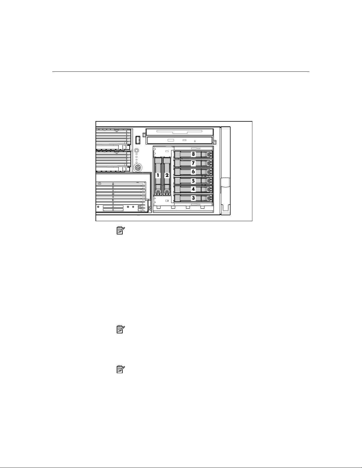
66 HP ProLiant DL580 Generation 3 Server User Guide
4. Resume normal server operations.
SAS and SATA hard drive guidelines
NOTE: The server may look different from that shown.
When adding SAS hard drives to the server, observe the following general
guidelines:
• The server supports eight SAS or SATA hot-plug hard drives.
• The system automatically sets all drive numbers.
• If only one hard drive is used, install it in the bay with the lowest number.
• Hard drives must be SFF types.
• Drives must be the same capacity to provide the greatest storage space
efficiency when drives are grouped together into the same drive array.
NOTE: ACU does not support mixing SAS and SATA drives in the
same logical volume.
Installing the SAS hard drive cage
NOTE: You must provide a SAS controller before proceeding with
the SAS hard drive cage installation.
Page 67
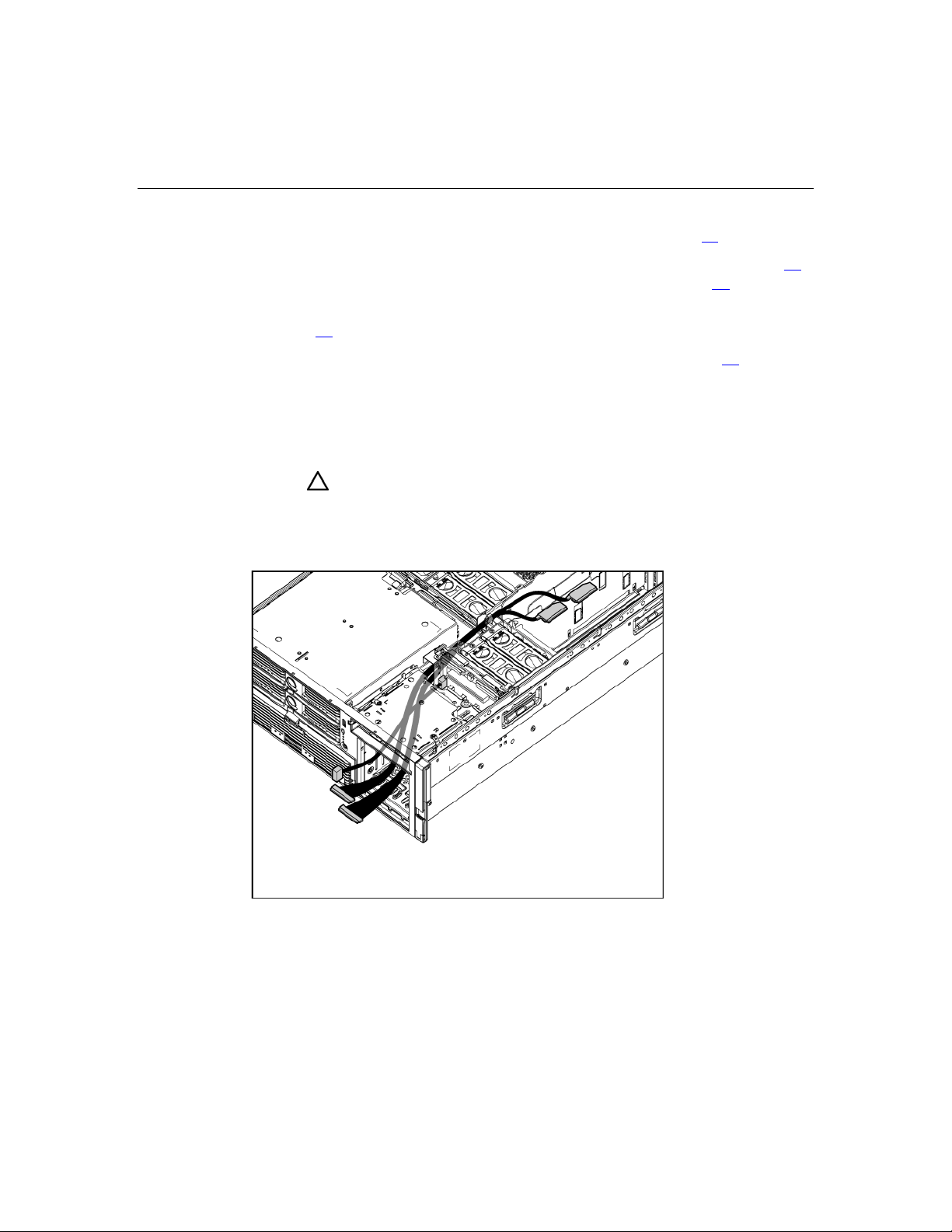
Hardware options installation 67
1. Power down the server ("Powering down the server" on page 37).
2. Remove all hard drives ("Removing a hot-plug SCSI hard drive" on page 64
and hard drive blanks ("Removing a hard drive blank" on page 63
).
)
3. Extend the server from the rack ("Extending the server from the rack" on
page 38
4. Remove the access panel ("Removing the access panel" on page 40
).
).
5. Install the SAS controller. Refer to the directions provided with the controller
for installation instructions.
6. Route and connect the power cable to the power cable connector on the SCSI
backplane.
CAUTION: When routing cables, always be sure that the cables
are not in a position where they can be pinched or crimped.
7. Route the SAS cables through the opening near the SCSI backplane and over
the center wall.
8. Connect the cables to the connectors on the back of the SAS hard drive cage.
Page 68
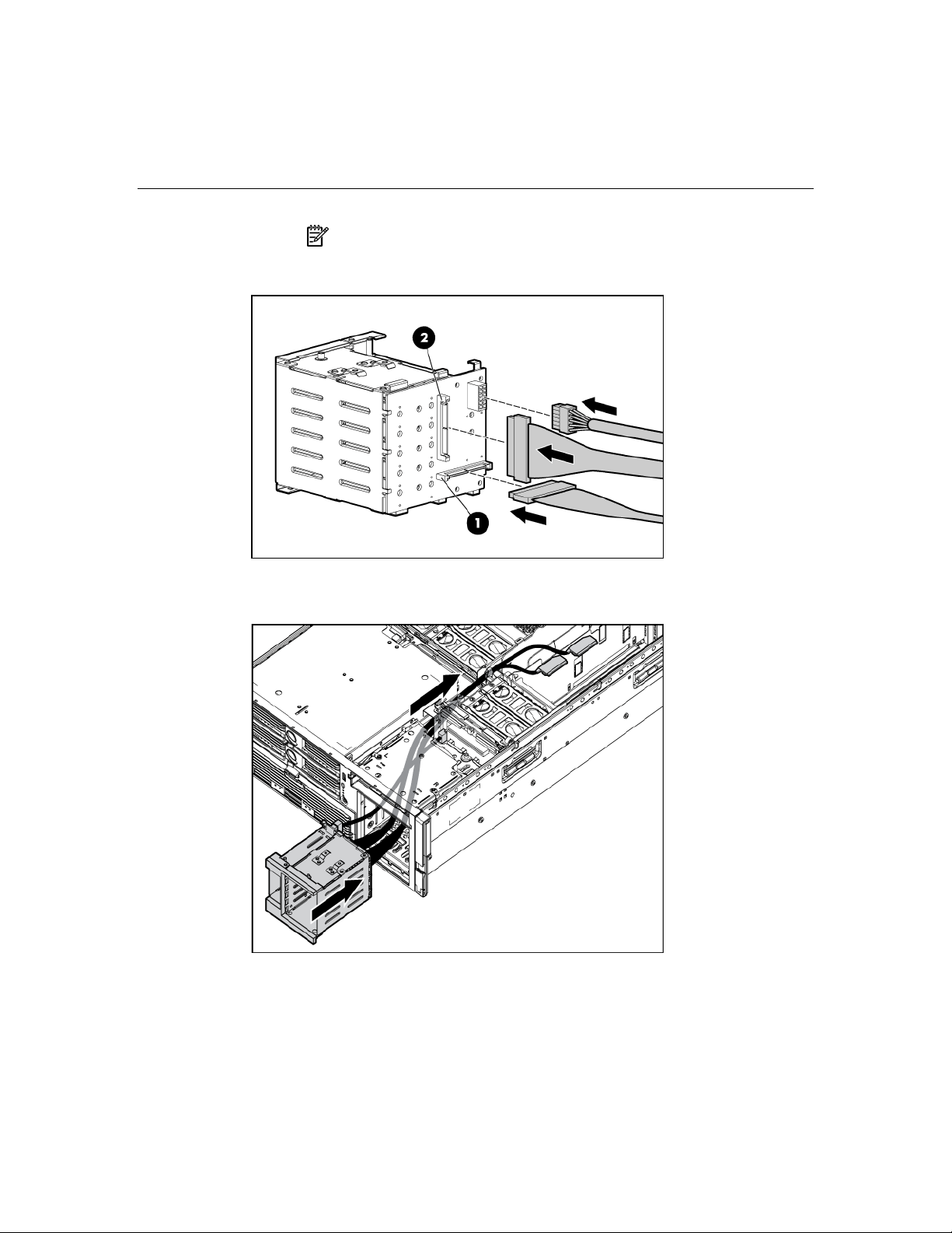
68 HP ProLiant DL580 Generation 3 Server User Guide
NOTE: Port 1 supports hard drives 1 through 4. Port 2 supports
hard drives 5 through 8. If you are using a single channel SAS
controller, connect the cable to port 1.
9. Install the SAS hard drive cage, pulling the slack in the SAS cables over the
center wall.
10. Connect the SAS cables to the controller.
Page 69

Hardware options installation 69
11. Secure the SAS hard drive cage with the screws provided in the option kit.
12. Install the hot-plug hard drives or hard drive blanks into the SAS hard drive
cage.
CAUTION: To prevent improper cooling and thermal damage, do
not operate the server unless all bays are populated with either a
component or a blank.
Installing a hot-plug SAS hard drive
IMPORTANT: The SAS hard drive cage ("Installing the SAS hard
drive cage" on page 66
hot-plug SAS or SATA hard drives.
1. Remove the hard drive blank.
) must be installed before installing the optional
Page 70

70 HP ProLiant DL580 Generation 3 Server User Guide
2. Prepare the SAS hard drive.
3. Install the hard drive.
4. Determine the status of the hard drive from the hot-plug SAS hard drive LED
combinations ("SAS and SATA hard drive LED combinations" on page 31
).
Page 71

Hardware options installation 71
Redundant hot-plug power supply
The server supports a second hot-plug power supply to provide redundant power
to the server in the event of a failure in the primary power supply. You can install
or replace a second hot-plug power supply without powering down the server.
WARNING: To reduce the risk of electric shock or damage to
the equipment:
• Do not disable the power cord grounding plug. The grounding
plug is an important safety feature.
• Plug the power cord into a grounded (earthed) electrical outlet
that is easily accessible at all times.
• Unplug the power cord from the power supply to disconnect
power to the equipment.
• Do not route the power cord where it can be walked on or
pinched by items placed against it. Pay particular attention to
the plug, electrical outlet, and the point where the cord extends
from the server.
CAUTION: If only one power supply is installed, do not remove the
power supply unless the server has been powered down. Removing the
only operational power supply will cause an immediate power loss.
NOTE: If you remove or replace the primary hot-plug power
supply, use the T-15 Torx screwdriver provided with the server to
remove the shipping screw. It is located just under the port-colored
plastic handle of the power supply unit.
Page 72
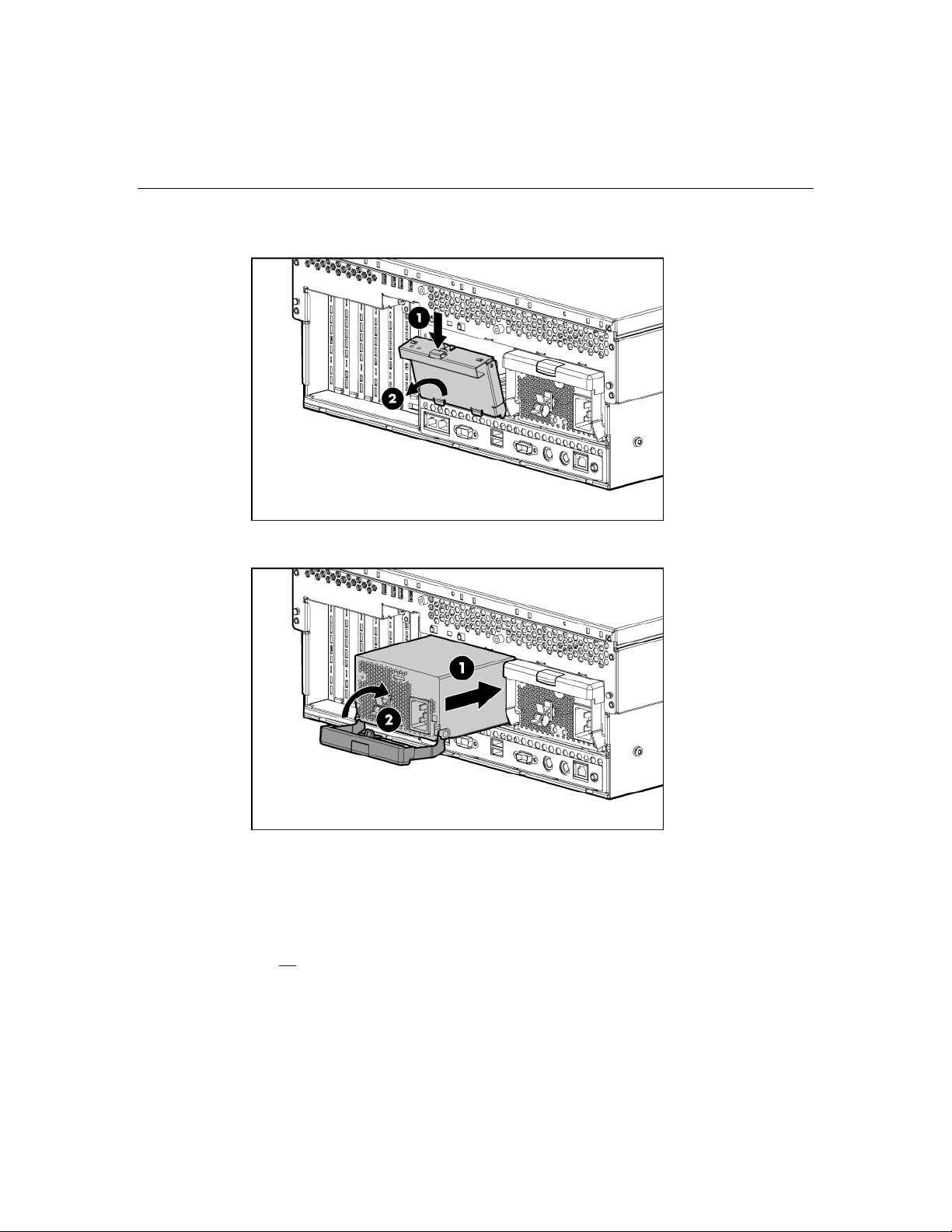
72 HP ProLiant DL580 Generation 3 Server User Guide
1. Remove the power supply blank.
2. Install the hot-plug power supply, and lock the lever.
3. Connect the power cord to the redundant power supply.
4. Secure the power cords to the retaining clip.
5. Connect the power cord to the power source.
6. Be sure that the power supply LED is green ("Power supply LEDs" on page
).
18
Page 73

Hardware options installation 73
7. Be sure that the front panel external health LED is green ("Front panel LEDs
and buttons" on page 11
IMPORTANT: For maximum server availability, be sure that the
two power supplies are powered by separate AC power sources.
NOTE: If the server will be shipped to another location after
configuration, install a shipping screw into each power supply.
).
Battery-Backed Write Cache
Along with the cache module, the battery pack provides transportable data
protection, increases overall controller performance, and maintains any cached
data for up to 72 hours after the server loses power. The NiMH batteries in the
battery pack are continuously recharged through a trickle-charging process
whenever the system power is on.
For information on BBWC LEDs, refer to "BBWC LEDs (on page 35
CAUTION: To prevent a server malfunction or damage to the
equipment, do not add or remove the battery pack while an array
capacity expansion, RAID level migration, or stripe size migration is in
progress.
CAUTION: After the server is powered down, wait 15 seconds and
then check the amber LED before unplugging the cable from the cache
module. If the amber LED blinks after 15 seconds, do not remove the
cable from the cache module. The cache module is backing up data,
and data will be lost if the cable is detached.
IMPORTANT: The battery pack may have a low charge when
installed. In this case, a POST error message is displayed when the
server is powered up, indicating that the battery pack is temporarily
disabled. No action is necessary on your part. The internal circuitry
automatically recharges the batteries and enables the battery pack. This
process may take up to 4 hours. During this time, the cache module will
function properly, but without the performance advantage of the battery
pack.
NOTE: The data protection and the time limit also apply if a power
outage occurs. When power is restored to the system, an initialization
process writes the preserved data to the hard drives.
To install the BBWC battery pack and cache module:
)."
Page 74

74 HP ProLiant DL580 Generation 3 Server User Guide
1. Power down the server ("Powering down the server" on page 37).
2. Extend the server from the rack, if applicable ("Extending the server from the
rack" on page 38
).
3. Remove the access panel ("Removing the access panel" on page 40
4. Remove the system cage ("Removing the system cage" on page 42
IMPORTANT: The BBWC cable is wound around the battery pack.
Unwind the cable to the appropriate length before installing the battery
pack assembly into the server.
5. Install the battery pack assembly into the server.
6. Route the cable along the system board.
).
).
7. Locate the cache module socket.
Page 75
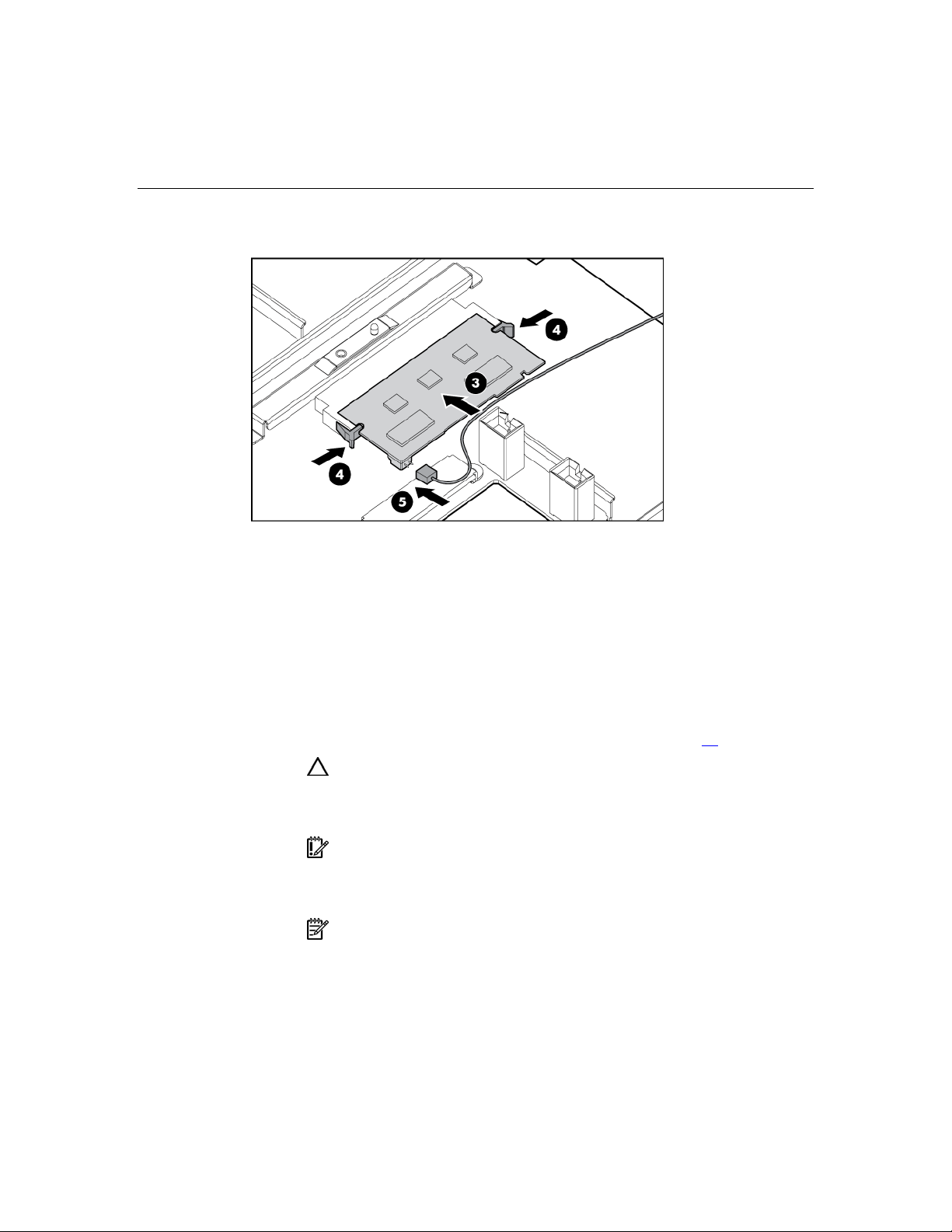
Hardware options installation 75
8. Install the cache module, and connect the BBWC cable to the cache module.
To reinstall all components, reverse the removal procedures.
DVD, diskette, and CD-RW drives
The server is shipped with one DVD drive. You can install an optional DVD
drive, 3.5-inch diskette drive, or CD-RW drive.
To install an optional media drive:
1. Power down the server ("Powering down the server" on page 37
CAUTION: Always populate each media bay with either a device
or a blank. Proper airflow can only be maintained when the bays are
populated. Unpopulated drive bays can lead to improper cooling and
thermal damage.
IMPORTANT: By default, the DVD drive is installed in the lower
drive bay. To boot from a DVD or CD-RW drive in the upper drive bay or
to boot from a diskette drive in the lower bay, change the boot device
selector switch to FLP BOT.
NOTE: If two optical drives are installed in the server, the server
will first attempt to boot from the primary optical drive. The boot device
selector switch setting determines which drive is the primary optical
drive.
).
Page 76

76 HP ProLiant DL580 Generation 3 Server User Guide
2. Use the T-15 Torx screwdriver to eject the drive blank, and pull the drive
blank out of the server.
NOTE: The T-15 Torx screwdriver is shipped with the server and
can be located on the rear panel ("Rear panel components" on page
16
).
3. Install the media drive into the server.
4. Power up the server ("Powering up the server" on page 37
).
Page 77

77
Expansion board options
In this section
Expansion slot overview...............................................................................................................77
Installing the PCI-X Hot Plug Mezzanine Option........................................................................81
Installing the PCI Express mezzanine options..............................................................................86
Installing non-hot-plug expansion boards ....................................................................................89
Installing hot plug expansion boards............................................................................................91
Removing a PCI-X Hot Plug expansion board.............................................................................92
RILOE II Board............................................................................................................................93
Expansion slot overview
The server supports up to seven expansion slots. When the server is shipped, it is
equipped with five expansion slots (slots 3 through 7) and two connectors to add
two optional expansion slots (slots 1 and 2).
To support the optional expansion slots, install one of the following into the
server:
• PCI-X Hot Plug mezzanine option (on page 79
Hot Plug expansion slots
• PCI Express x4 mezzanine option ("PCI Express mezzanine options" on page
80
)—Adds two optional PCI Express x4 expansion slots
• PCI Express x8 mezzanine option ("PCI Express mezzanine options" on page
)—Adds one optional PCI Express x8 expansion slot
80
)—Adds two optional PCI-X
Page 78

78 HP ProLiant DL580 Generation 3 Server User Guide
NOTE: Only one mezzanine option can be installed in the server.
Item Slot Description
1 1–2 Connectors for one of the following:
• Optional PCI Express x4 mezzanine
board
• Optional PCI Express x8 mezzanine
board
• Optional PCI-X Hot Plug mezzanine
board
2 3 PCI-X non-hot-plug expansion slot, 64-
bit/133-MHz
3 4 PCI-X non-hot-plug expansion slot, 64-
bit/133-MHz
4 5 PCI-X non-hot-plug expansion slot, 64-
bit/133-MHz
5 6 PCI-X non-hot-plug expansion slot, 64-
bit/100-MHz
6 7 PCI-X non-hot-plug expansion slot, 64-
bit/100-MHz
Page 79

Expansion board options 79
PCI-X Hot Plug Mezzanine Option
The PCI-X Hot Plug Mezzanine Option adds support for two optional PCI-X Hot
Plug expansion slots.
Item Description
1 PCI-X Hot Plug expansion slot 1, 64-
bit/133-MHz
2 PCI-X Hot Plug expansion slot 2, 64-
bit/133-MHz
Page 80

80 HP ProLiant DL580 Generation 3 Server User Guide
PCI Express mezzanine options
The PCI Express x4 mezzanine option adds support for two optional PCI Express
x4 non-hot-plug expansion slots in slots 1 and 2.
Item Description
1 PCI Express x4 non-hot-plug
expansion slot 1
2 PCI Express x4 non-hot-plug
expansion slot 2
Page 81

Expansion board options 81
The PCI Express x8 mezzanine option adds support for one optional PCI Express
x8 non-hot-plug expansion slot in slot 1.
Installing the PCI-X Hot Plug Mezzanine Option
1. Power down the server ("Powering down the server" on page 37).
2. Extend or remove the server from the rack ("Extending the server from the
rack" on page 38
3. Remove the access panel ("Removing the access panel" on page 40
).
).
Page 82

82 HP ProLiant DL580 Generation 3 Server User Guide
4. Adhere the PCI-X Hot Plug label to the power supply cover.
5. Remove the expansion boards from slots 3 and 4, if installed, to gain access
to the mezzanine connectors.
6. Remove the expansion slot covers from slots 1 and 2.
7. Connect the hot-plug cable to the mezzanine board.
Page 83

Expansion board options 83
NOTE: The cable connector is keyed at pin 1 for alignment.
8. Use the guide pins to align the mezzanine board, and seat the mezzanine
board onto the system board.
9. Tighten the three thumbscrews to secure the mezzanine board.
Page 84

84 HP ProLiant DL580 Generation 3 Server User Guide
10. Install the PCI-X Hot Plug board.
11. Route the cable from the mezzanine board to the hot-plug board, and connect
the cable.
Page 85

Expansion board options 85
12. Attach the latch to the chassis, and press down until it snaps into place.
13. Install the retaining clips.
Page 86
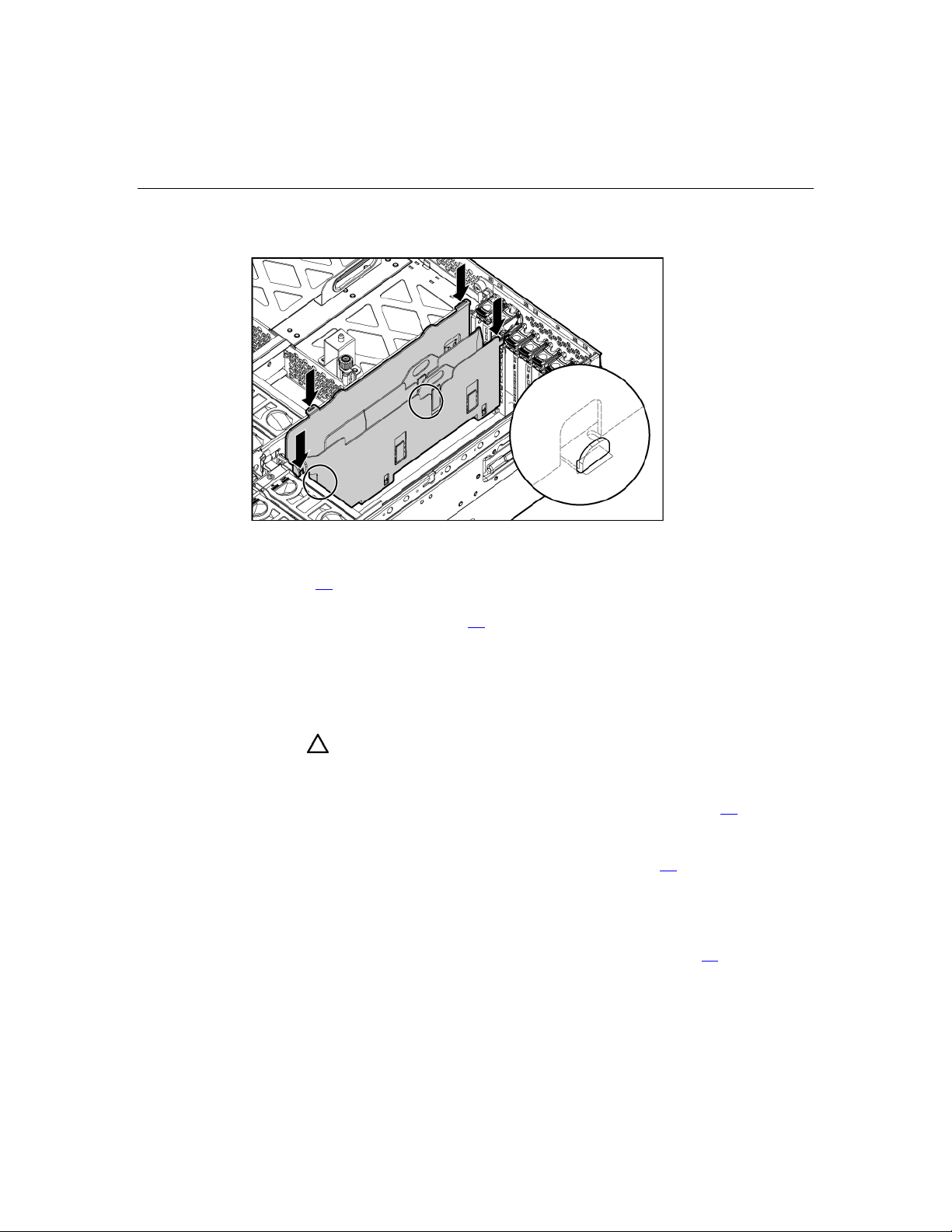
86 HP ProLiant DL580 Generation 3 Server User Guide
14. Install the basket.
15. Install the PCI-X Hot Plug expansion boards. If the server is powered off,
use non-hot-plug procedures ("Installing non-hot-plug expansion boards" on
page 89
) to install the expansion boards. If the server is running, install PCIX Hot Plug expansion boards using hot-plug procedures ("Installing hot plug
expansion boards" on page 91
).
16. Reinstall any expansion boards removed to install the PCI-X Hot Plug
Mezzanine Option.
17. Place the expansion slot covers over any remaining empty expansion slots,
and close the latches.
CAUTION: To prevent improper cooling and thermal damage, do
not operate the server unless all expansion slots have either an
expansion slot cover or an expansion board installed.
18. Replace the access panel ("Removing the access panel" on page 40).
19. Slide the server back into the rack.
20. Power up the server ("Powering up the server" on page 37
).
Installing the PCI Express mezzanine options
1. Power down the server ("Powering down the server" on page 37).
Page 87

Expansion board options 87
2. Extend or remove the server from the rack ("Extending the server from the
rack" on page 38
).
3. Remove the access panel ("Removing the access panel" on page 40
).
4. Remove the expansion boards from slots 3 and 4, if installed, to gain access
to the mezzanine connectors.
5. Remove the expansion slot covers from slots 1 and 2.
6. Use the guide pins to align the mezzanine board, and seat the mezzanine
board onto the system board.
7. Tighten the three thumbscrews to secure the mezzanine board.
Page 88

88 HP ProLiant DL580 Generation 3 Server User Guide
NOTE: The PCI Express x8 mezzanine board is shown.
8. Attach the latch to the chassis, and press down until it snaps into place.
Page 89

Expansion board options 89
9. Install the retaining clip.
10. Install the PCI Express x8 non-hot-plug expansion board ("Installing non-
hot-plug expansion boards" on page 89
)into slot 1, if installing the PCI
Express x8 mezzanine option. Install the PCI Express x4 non-hot-plug
expansion boards into slots 1 and 2, if installing the PCI Express x4
mezzanine option.
11. Place expansion slot covers over any remaining empty slots, and close the
latches.
CAUTION: To prevent improper cooling and thermal damage, do
not operate the server unless all expansion slots have either an
expansion slot cover or an expansion board installed.
12. Replace the access panel ("Removing the access panel" on page 40).
13. Slide the server back into the rack.
14. Power up the server ("Powering up the server" on page 37
Installing non-hot-plug expansion boards
CAUTION: To prevent damage to the server or expansion boards,
power down the server and remove all AC power cords before removing
or installing the expansion boards.
).
Page 90
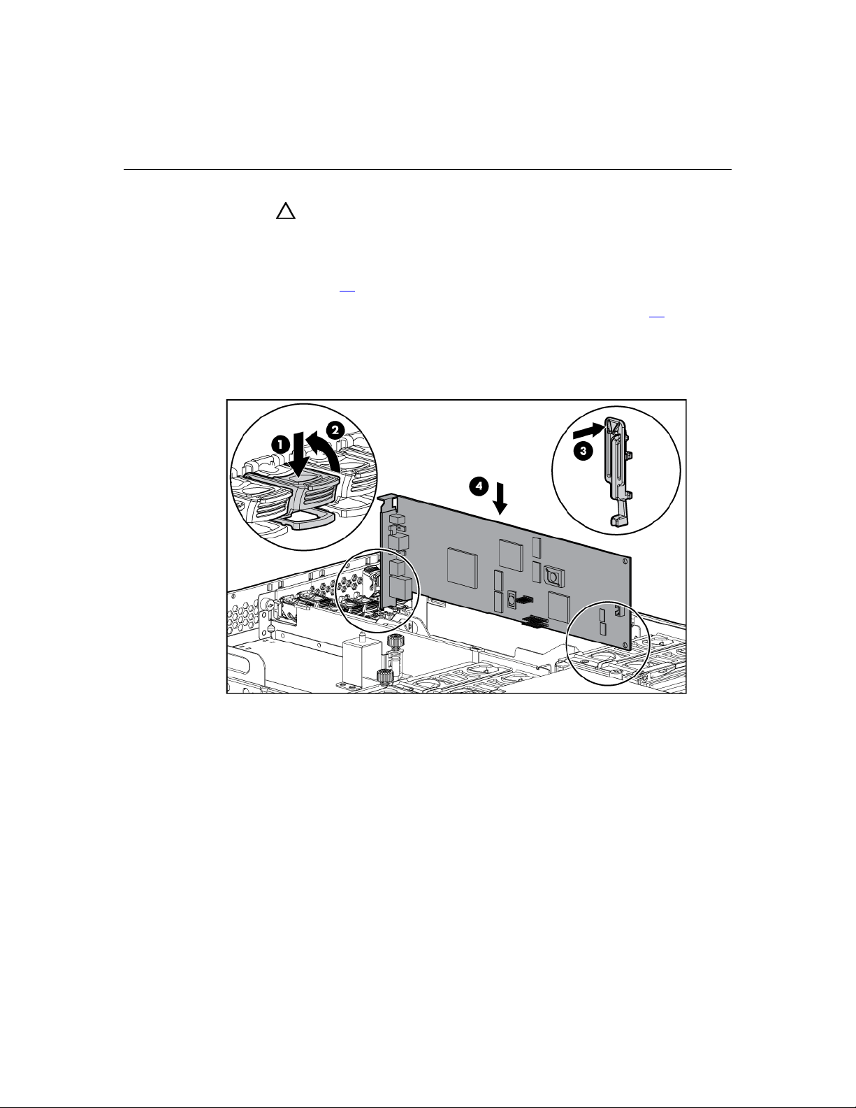
90 HP ProLiant DL580 Generation 3 Server User Guide
CAUTION: To prevent improper cooling and thermal damage, do
not operate the server unless all expansion slots have either an
expansion slot cover or an expansion board installed.
1. Extend or remove the server from the rack ("Extending the server from the
rack" on page 38
).
2. Remove the access panel ("Removing the access panel" on page 40
).
3. Open the latch, and remove the expansion slot cover.
4. Unlock the retaining clip (for full-length expansion boards), and install the
non-hot-plug expansion board.
5. Lock the retaining clip (for full-length expansion boards), and close the latch.
6. Connect any required internal or external cables to the expansion board.
7. Replace the access panel, and resume normal server operations.
To remove a non-hot-plug expansion board, reverse the installation procedures.
Page 91

Expansion board options 91
Installing hot plug expansion boards
For hot-plug capability, the PCI-X Hot Plug Mezzanine Option (on page 79)
must be installed before installing PCI-X Hot Plug expansion boards in the
server.
CAUTION: To prevent improper cooling and thermal damage, do
not operate the server unless all expansion slots have either an
expansion slot cover or an expansion board installed.
1. Extend or remove the server from the rack ("Extending the server from the
rack" on page 38
).
2. Remove the access panel ("Removing the access panel" on page 40
).
3. Press the PCI-X Hot Plug button to remove power from the slot. When the
green power LED on the slot stops flashing, power has been removed from
the slot.
4. Open the latch, and remove the expansion slot cover.
Page 92
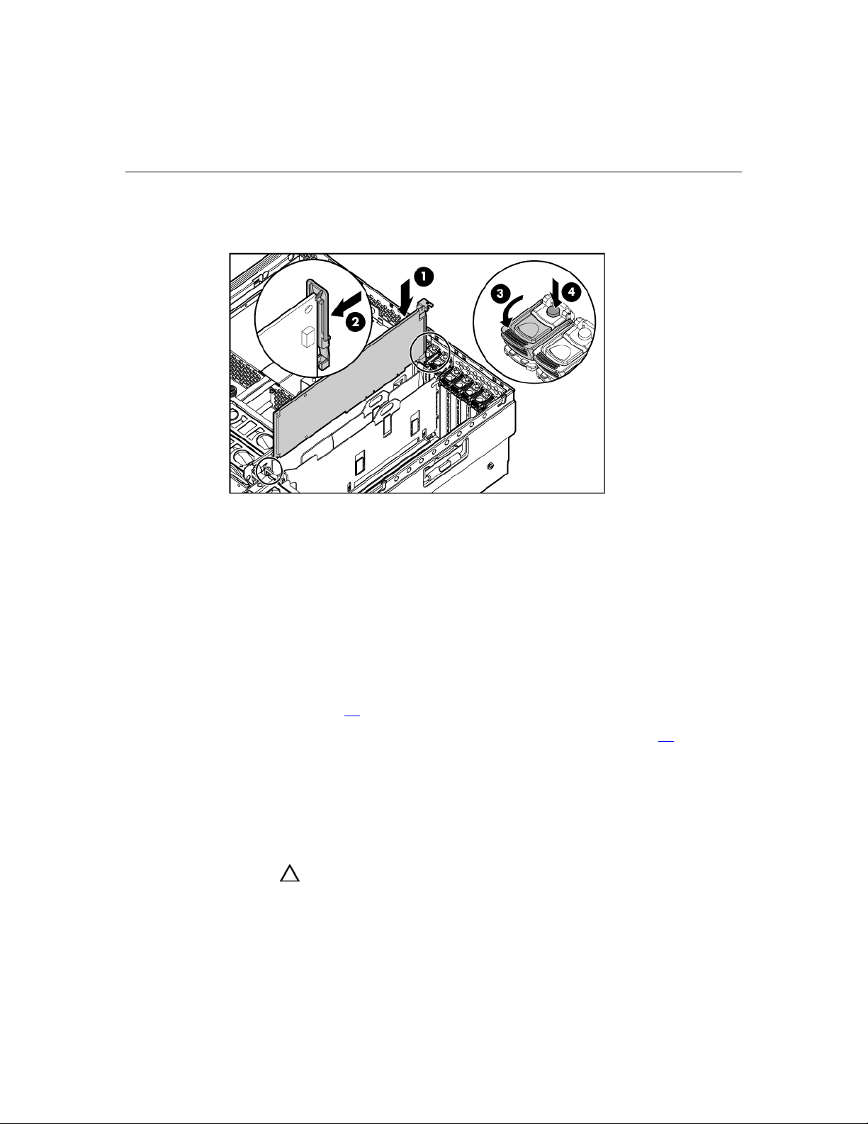
92 HP ProLiant DL580 Generation 3 Server User Guide
5. Unlock the retaining clip (for full-length expansion boards), and install the
PCI-X Hot Plug expansion board.
6. Lock the retaining clip (for full-length expansion boards), and close the latch.
7. Connect any required internal or external cables to the expansion board.
8. Press the PCI-X Hot Plug button, and wait for the power LED to illuminate
green without flashing.
9. Replace the access panel, and resume normal server operations.
Removing a PCI-X Hot Plug expansion board
1. Extend or remove the server from the rack ("Extending the server from the
rack" on page 38
2. Remove the access panel ("Removing the access panel" on page 40
3. Press the PCI-X Hot Plug button to remove power from the slot. When the
green power LED on the slot stops flashing, power has been removed from
the slot.
4. Unlock the retaining clip (for full-length expansion boards).
5. Lift the latch, and remove the board from the server.
CAUTION: To prevent improper cooling and thermal damage, do
not operate the server unless all expansion slots have either an
expansion slot cover or an expansion board installed.
).
).
Page 93

Expansion board options 93
To replace the component, reverse the removal procedure.
RILOE II Board
The server comes with iLO remote management capability embedded on the
system board. The 30-pin remote management connector for the RILOE II board
is provided to reduce external cabling. The 30-pin connector provides power,
keyboard, mouse, and other peripheral signals directly to the system board;
therefore, the external AC power adapter and keyboard/mouse loopback cable are
not needed for normal operations.
The RILOE II board provides remote server manageability for ProLiant servers.
It can be accessed from a network client using a standard web browser, and it
provides a keyboard, mouse, and video capability for a host server, regardless of
the state of the host operating system or host server. The RILOE II board features
include a faster processor for increased performance, new user interface for
easier browsing, and integration with LDAP, Virtual Floppy, and Virtual CD for
increased server manageability.
A built-in processor, memory, NIC, ROM, and standard external power supply
make the RILOE II board independent of the host server and its operating
system. This design allows the RILOE II board to provide remote access to any
authorized network client, send alerts, and perform other management functions.
Page 94

94 HP ProLiant DL580 Generation 3 Server User Guide
For information about iLO technology, refer to "Integrated Lights-Out
Technology (on page 132
)."
To install the RILOE II board:
IMPORTANT: Install the RILOE II board into slot 7 for ease of
cabling.
1. Power down the server ("Powering down the server" on page 37).
2. Remove the access panel ("Removing the access panel" on page 40
3. Install the RILOE II board into slot 7.
4. Connect the RILOE II cable ("RILOE II cabling" on page 117
) to the 30-pin
connector on the system board.
5. Connect the RILOE II cable to the RILOE II board.
).
Page 95

95
Memory options
In this section
Memory overview.........................................................................................................................95
Advanced ECC memory...............................................................................................................97
Online spare memory....................................................................................................................99
Hot-plug mirrored memory ........................................................................................................100
Hot-plug RAID memory.............................................................................................................102
Memory Boards and DIMMs .....................................................................................................103
Configuring the memory ............................................................................................................111
Memory overview
This server supports up to four memory boards. Each memory board contains
four DIMM slots for a total of 16 DIMM slots in the server. Memory can be
expanded by installing PC2-3200R Registered DDR2 DRAM DIMMs.
The server supports a host of AMP options to optimize server availability:
• Advanced ECC ("Advanced ECC memory" on page 97
• Online spare memory (on page 99
• Hot-plug mirrored memory (dual- and quad-board) ("Hot-plug mirrored
memory" on page 100
• Hot-plug RAID memory
Hot-plug operations can be hot-add or hot-replace. Hot-add makes additional
memory resources available to the operating system. Hot-replace allows failed or
degraded DIMMs to be replaced while the server is running.
The maximum supported total memory for this server is 64 GB using four
memory boards. The maximum supported memory per memory board is 16 GB
using four 4-GB DIMMs.
)
)
)
Page 96

96 HP ProLiant DL580 Generation 3 Server User Guide
For an overview of single- and dual-rank DIMMs, refer to "Single- and DualRank DIMMs."
For DIMM slot locations and bank assignments, refer to "DIMM Slot Locations
(on page 25
)."
General memory configuration requirements
The following configuration requirements apply regardless of the AMP mode.
• DIMMs must be installed in pairs.
• Dimms pairs in a memory bank must contain DIMMS with the same part
number.
• Always populate the DIMMs in sequential order per bank: Bank A and then
Bank B.
• Always populate the memory boards in sequential order: Board 1, Board 2,
Board 3, and Board 4. Any deviation from this requirement results in the
server defaulting to Advanced ECC ("Advanced ECC memory" on page 97
on the next reboot.
)
• Dual-rank DIMMs must be populated before single-rank DIMMs (dual-rank
DIMMs must be in the lower bank).
• The following table lists all valid combinations of single- and dual-rank
DIMM configurations for a memory board. "Single" indicates a bank of
single-rank DIMMs. "Dual" indicates a bank of dual-rank DIMMs.
Configuration Bank A Bank B
1 Single
2 Single Single
3 Dual
4 Dual Single
5 Dual Dual
NOTE: A bank contains 2 DIMMs.
Page 97

Memory options 97
• The server can be configured for any AMP mode in RBSU. RBSU displays a
warning message if the selected AMP mode is not supported by the current
DIMM configuration. However, if the DIMM configuration at POST does
not match the AMP mode selected in RBSU, the server defaults to Advanced
ECC ("Advanced ECC memory" on page 97
). When this occurs, a message
displays during POST and the status LED for the configured AMP mode
flashes amber.
• Unpopulated memory boards (those without any installed DIMMs) can be
installed in the server for storing extra memory boards.
• If your server contains more than 4 GB of memory, consult your operating
system documentation for additional requirements.
Single- and dual-rank DIMMs
PC2-3200 DIMMs can either be single- or dual-rank. While it is not normally
important for you to differentiate between these two types of DIMMs, certain
DIMM configuration requirements are based on these classifications.
Certain configuration requirements exist with single- and dual-rank DIMMs that
allow the architecture to optimize performance. A dual-rank DIMM is similar to
having two separate DIMMs on the same module. Although only a single DIMM
module, a dual-rank DIMM acts as if it were two separate DIMMs. The primary
reason for the existence of dual-rank DIMMs is to provide the largest capacity
DIMM given the current DIMM technology. If the maximum DIMM technology
allows for creating 2-GB single-rank DIMMs, a dual-rank DIMM using the same
technology would be 4-GB.
Advanced ECC memory
Advanced ECC is the default memory protection mode for this server. In
Advanced ECC, the server is protected against correctable memory errors. The
server will provide notification if the level of correctable errors exceeds a
predefined threshold rate. The server does not fail because of correctable
memory errors.
Page 98

98 HP ProLiant DL580 Generation 3 Server User Guide
Advanced ECC provides additional protection over Standard ECC in that it is
possible to correct certain memory errors that would otherwise be uncorrectable
and result in a server failure. Whereas Standard ECC can correct single-bit
memory errors, Advanced ECC can correct single-bit memory errors and multibit memory errors if all failed bits are on the same DRAM device on the DIMM.
The following guidelines apply to Advanced ECC memory:
• All general memory requirements apply.
• Advanced ECC mode is supported with one to four memory boards.
• Board insertions do not convert the AMP mode while the server is running.
A server cannot be converted from Advanced ECC to another AMP mode by
inserting a board while the server is running. Board insertions in Advanced
ECC are solely for making additional memory resources available to the
operating system.
• Advanced ECC is the only mode in which hot-add operations are supported,
and is the only mode in which the amount of memory available to the
operating system can be increased without a reboot.
• If a memory board (which contains DIMMs) is unlocked while in Advanced
ECC mode, audio alarms and visual alerts occur.
The following rules apply to hot-add operations. Hot-add is performed by adding
a memory board while the server is running, and the additional memory is made
available to the operating system without a reboot.
• Boards must be inserted sequentially.
• Multiple hot-add board insertions can be performed one at a time on the
same server. For example, if a server has three empty memory board slots,
three hot-add board insertions can be performed.
• If multiple hot-add operations are performed, allow one board insertion
operation to complete (as indicated by the memory board LEDs ("Memory
board components and LEDs" on page 12
) and operating system logs) before
inserting another memory board.
CAUTION: When the memory board locking switch is unlocked in
a mode that does not support hot-add or hot-replace capabilities, audio
alarms and visual alerts occur. Removing the memory board at this
point causes server failure.
Page 99

Memory options 99
To end the audio alarms and visual alerts, move the memory board
locking switch back to the locked position. This action does not result in
data corruption or server failure.
If removal of a single memory board is required and it is the only
memory board, power down the server and make the necessary
memory changes.
Online spare memory
Online spare memory provides a higher level of memory protection than
Advanced ECC ("Advanced ECC memory" on page 97
memory, the probability of a server failing because of uncorrectable memory
errors is reduced.
In this mode, degraded memory that is receiving a high rate of correctable
memory errors is automatically disengaged and a replacement set of memory is
used in its place. Because DIMMs that are receiving a high rate of correctable
memory errors have an increased probability of receiving an uncorrectable
memory error (which results in a server failure), the server experiences higher
availability. The degraded memory can be replaced during scheduled downtime
and poses no additional risk to the server.
). With online spare
Online spare memory is supported with one to four memory boards installed. On
this server, each installed memory board is protected by its own spare memory.
No operating system support is required.
The following guidelines apply to online spare memory:
• All general memory requirements apply.
• Online spare memory supports 1, 2, 3, or 4 memory boards.
• Each board must have a valid online spare configuration. No dependencies
exist for the configuration between different memory boards.
• Each memory board includes its own online spare bank. All boards will
operate in online spare memory mode independently. Each board can
failover to its online spare bank independent of the other memory boards.
Some boards can be in degraded online spare mode while others are still in
operational online spare memory mode.
Page 100

100 HP ProLiant DL580 Generation 3 Server User Guide
• The minimum valid online spare configuration for a memory board requires
at least one bank of dual-rank DIMMs or two banks of single-rank DIMMs.
If the server does not meet these requirements, an error message appears
during POST and the server defaults to Advanced ECC ("Advanced ECC
memory" on page 97
).
• The server automatically configures the optimal online spare solution.
• Hot-plug operations are not supported.
HP recommends the following configurations. These configurations result in
optimal use of memory. Other configurations are valid, but do not result in the
maximum amount of installed memory being available to the operating system.
• If only single-rank DIMMs are used on a memory board, all DIMMs should
be of the same size on that memory board.
• If only dual-rank DIMMs are used on a memory board, all DIMMs should be
of the same size on that memory board.
• If a mixture of single- and dual-rank DIMMs are used on a memory board,
the dual-rank DIMMs should be twice the size of any single-rank DIMM.
After installing DIMMs, use RBSU to configure the server ("Configuring the
memory" on page 111
) for online spare memory support.
Hot-plug mirrored memory
Hot-plug mirrored memory provides a higher level of memory protection than
either Advanced ECC ("Advanced ECC memory" on page 97
memory (on page 99
against uncorrectable memory errors that would otherwise result in server failure.
Hot-plug mirrored memory allows the server to keep two copies of all memory
data on separate memory boards.
If an uncorrectable error is encountered, the proper data is retrieved from the
memory board that did not fail. In addition, hot-plug mirrored memory allows
failed or degraded DIMMs to be replaced while the server is running without
requiring server downtime. The memory board with the failed DIMMs can be
removed, failed DIMMs replaced, and the board re-inserted into the server
without any interruption to the operating system.
). With hot-plug mirrored memory, the server is protected
) or online spare
 Loading...