

Page 1

HP ProLiant DL580 Generation 3 Server Maintenance and Service Guide
May 2006 (Sixth Edition)
Part Number 379041-006
Page 2

© Copyright 2005, 2006 Hewlett-Packard Development Company, L.P.
The information contained herein is subject to change without notice. The only warranties for HP products and services are set forth in the express
warranty statements accompanying such products and services. Nothing herein should be construed as constituting an additional warranty. HP
shall not be liable for technical or editorial errors or omissions contained herein.
Microsoft, Windows, and Windows NT are U.S. registered trademarks of Microsoft Corporation. Windows Server 2003 is a trademark of
Microsoft Corporation. Intel and Xeon are trademarks or registered trademarks of Intel Corporation or its subsidiaries in the United States and
other countries. Linux is a U.S. registered trademark of Linus Torvalds.
May 2006 (Sixth Edition)
Part Number 379041-006
Audience assumptions
This document is for the person who installs, administers, and troubleshoots servers and storage systems.
HP assumes you are qualified in the servicing of computer equipment and trained in recognizing hazards
in products with hazardous energy levels.
Page 3

Contents
Illustrated parts catalog ................................................................................................................. 6
Customer self repair................................................................................................................................... 6
Mechanical components............................................................................................................................. 6
System components ...................................................................................................................................8
Removal and replacement procedures........................................................................................... 13
Required tools......................................................................................................................................... 13
Safety considerations............................................................................................................................... 14
Preventing electrostatic discharge .................................................................................................... 14
Server warnings and cautions ......................................................................................................... 14
Preparation procedures............................................................................................................................ 14
Extending the server from the rack ................................................................................................... 15
Power down the server................................................................................................................... 16
Remove the server from the rack...................................................................................................... 16
Removing the access panel............................................................................................................. 17
Removing the system cage.............................................................................................................. 17
Removing the front bezel.......................................................................................................................... 18
Removing a media drive blank.................................................................................................................. 19
Removing a media drive ..........................................................................................................................19
Removing the processor module ................................................................................................................ 20
Removing a processor.............................................................................................................................. 22
Removing a PPM..................................................................................................................................... 25
Removing a PCI latch............................................................................................................................... 26
Removing a PCI retaining clip...................................................................................................................27
Removing the PCI-X Hot Plug basket........................................................................................................... 28
Removing a non-hot-plug expansion board .................................................................................................28
Removing the PCI-X Hot Plug mezzanine option........................................................................................... 29
Removing the PCI Express mezzanine option ..............................................................................................30
Recovering data from the BBWC............................................................................................................... 30
Removing the BBWC battery pack............................................................................................................. 31
Removing the BBWC cache module........................................................................................................... 32
Removing the system board ...................................................................................................................... 32
Re-entering the server serial number and product ID........................................................................... 34
Removing the system battery ..................................................................................................................... 35
Removing the media board....................................................................................................................... 37
Removing the SCSI backplane .................................................................................................................. 37
Removing the power backplane ................................................................................................................39
Removing the memory backplane .............................................................................................................. 39
Removing a hard drive blank.................................................................................................................... 40
Removing a hot-plug SCSI hard drive......................................................................................................... 40
Removing a hot-plug SAS hard drive.......................................................................................................... 41
Removing the SAS-SATA hard drive cage...................................................................................................42
Removing the SAS-SATA backplane........................................................................................................... 46
Removing a PCI-X Hot Plug expansion board ..............................................................................................47
Removing a power supply blank................................................................................................................ 48
Removing a redundant hot-plug power supply............................................................................................. 48
Replacing hot-plug fans............................................................................................................................ 49
Memory overview ................................................................................................................................... 50
General memory configuration requirements ..................................................................................... 50
Single- and dual-rank DIMMs .......................................................................................................... 51
Contents 3
Page 4

Advanced ECC memory ................................................................................................................. 51
Online spare memory .................................................................................................................... 52
Hot-plug mirrored memory .............................................................................................................. 53
Hot-plug RAID memory...................................................................................................................54
Configuring the memory................................................................................................................. 55
Memory boards and DIMMs........................................................................................................... 56
Diagnostic tools.......................................................................................................................... 60
SmartStart software ................................................................................................................................. 60
SmartStart Scripting Toolkit....................................................................................................................... 60
HP Instant Support Enterprise Edition.......................................................................................................... 61
Option ROM Configuration for Arrays ....................................................................................................... 61
HP ROM-Based Setup Utility ..................................................................................................................... 61
ROMPaq utility........................................................................................................................................ 62
System Online ROM flash component utility ................................................................................................ 62
Integrated Management Log ..................................................................................................................... 62
Integrated Lights-Out technology................................................................................................................ 63
Automatic Server Recovery ....................................................................................................................... 63
HP Systems Insight Manager..................................................................................................................... 63
HP Insight Diagnostics.............................................................................................................................. 63
USB support ...........................................................................................................................................64
Troubleshooting the system using port 85 codes .......................................................................................... 64
Processor-related port 85 codes....................................................................................................... 64
Expansion board-related port 85 codes............................................................................................ 65
Memory-related port 85 codes ........................................................................................................ 66
Miscellaneous port 85 codes .......................................................................................................... 66
Server component identification.................................................................................................... 68
Front panel components ........................................................................................................................... 68
Front panel LEDs and buttons .................................................................................................................... 69
Memory board components and LEDs ........................................................................................................ 70
Processor module LEDs............................................................................................................................. 72
Rear panel components............................................................................................................................ 73
Rear panel LEDs and buttons..................................................................................................................... 74
Power supply LEDs................................................................................................................................... 75
System board components........................................................................................................................ 76
System maintenance switch............................................................................................................. 77
Boot device selector switch ............................................................................................................. 77
QuickFind diagnostic display LEDs................................................................................................... 78
Setting the switch to view port 85 codes........................................................................................... 80
DIMM slot locations................................................................................................................................. 80
SCSI IDs................................................................................................................................................. 80
Hot-plug SCSI hard drive LEDs ..................................................................................................................82
Hot-plug SCSI hard drive LED combinations ................................................................................................ 82
SATA or SAS IDs..................................................................................................................................... 83
SATA or SAS hard drive LEDs ................................................................................................................... 84
SAS and SATA hard drive LED combinations ..............................................................................................84
Fan locations .......................................................................................................................................... 85
Hot-plug fan LEDs .................................................................................................................................... 87
BBWC LEDs............................................................................................................................................ 87
Server cabling............................................................................................................................ 89
Storage device cabling guidelines.............................................................................................................89
PCI-X Hot Plug mezzanine cabling............................................................................................................. 89
BBWC cabling........................................................................................................................................ 90
Contents 4
Page 5

RILOE II cabling ......................................................................................................................................90
Hot-plug SCSI drive cabling...................................................................................................................... 91
SCSI simplex mode........................................................................................................................ 92
SCSI duplex mode......................................................................................................................... 92
Hot-plug SAS hard drive cabling ............................................................................................................... 92
USB cable assembly ................................................................................................................................ 93
Power switch cable assembly.................................................................................................................... 94
Specifications............................................................................................................................. 96
Server specifications................................................................................................................................96
Environmental specifications ..................................................................................................................... 96
Hot-plug power supply calculations............................................................................................................ 97
Acronyms and abbreviations........................................................................................................ 98
Index....................................................................................................................................... 102
Contents 5
Page 6
Illustrated parts catalog
In this section
Customer self repair ................................................................................................................................. 6
Mechanical components ........................................................................................................................... 6
System components .................................................................................................................................. 8
Customer self repair
What is customer self repair?
HP's customer self-repair program offers you the fastest service under either warranty or contract. It
enables HP to ship replacement parts directly to you so that you can replace them. Using this program,
you can replace parts at your own convenience.
A convenient, easy-to-use program:
• An HP support specialist will diagnose and assess whether a replacement part is required to address
a system problem. The specialist will also determine whether you can replace the part.
• Replacement parts are express-shipped. Most in-stock parts are shipped the very same day you
contact HP. You may be required to send the defective part back to HP, unless otherwise instructed.
• Available for most HP products currently under warranty or contract. For information on the warranty
service, refer to the HP website
(http://h18004.www1.hp.com/products/servers/platforms/warranty/index.html
For more information about HP's customer self-repair program, contact your local service provider. For the
North American program, refer to the HP website (http://www.hp.com/go/selfrepair
Customer replaceable parts are identified in the following tables.
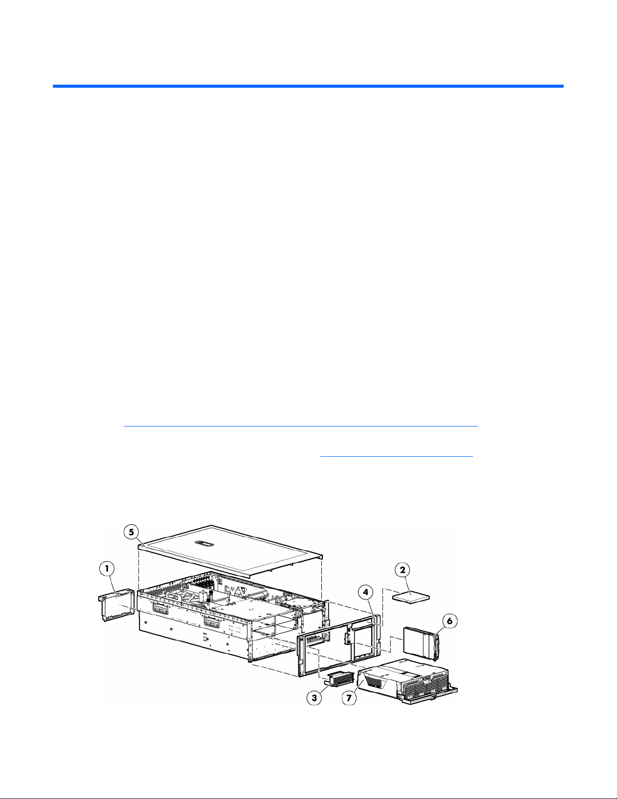
Mechanical components
).
).
Illustrated parts catalog 6
Page 7

Item Description
Original
assembly part
number
Modified
assembly
part
Original spare
part number
Modified
spare part
number
Customer
self repair
number
—
Hardware kit, ProLiant
— — 385642-001 — Yes
DL580 G3 Server *
1
a) Blank, power
366450-002 — — — Yes
supply
2
b) Blank,
377569-001 — — — Yes
CD/DVD/diskette
3
c) Blank, memory
374278-001 — — — Yes
board
4
Bezel, ProLiant DL580
367600-001 — 376481-001 — Yes
G3 Server
5
Cover, top, ProLiant
367572-001 — 376480-001 — Yes
DL580 G3 Server
6 Blank, hard drive 302531-002 — 122759-001 — Yes
7 Plastics kit — — 376479-001 — Yes
8
a) Guide, PCA, short
367597-001 — — — Yes
(2) *
9
b) Guide, PCA, tall (2)
367939-001 — — — Yes
*
10
c) Latch, PCI, carbon
228194-001 — — — Yes
(2) *
11
d) Latch, PCA, blue
228194-002 — — — Yes
(2) *
12
e) Retainer, card
379046-001 — — — Yes
guide, carbon (2) *
13
f) Retainer, card
379046-002 — — — Yes
guide, blue (2) *
14
Return kit, ProLiant
— — 378336-001 — Yes
DL580 G3 Server *
15 Tool, Torx, T-15* 107473-001 — 199630-001 — Yes
* not shown
‡REQUIREMENT:
For Customers in the EU only.
The use of the Original Spare part is regulated by RoHS legislation§.
If your unit contains a part that is labelled with the Modified Spare number, the Modified Spare must be ordered as
the replacement part in the EU.
If your unit contains a part that is labelled with the Original Spare number, please order the Original Spare as the
replacement part in the EU. In this case either the Original Spare or the Modified Spare may be shipped which will
not affect performance or functionality of the unit.
§Directive 2002/95/EC restricts the use of lead, mercury, cadmium, hexavalent chromium, PBBs and PBDEs in
electronic products.
Illustrated parts catalog 7
Page 8
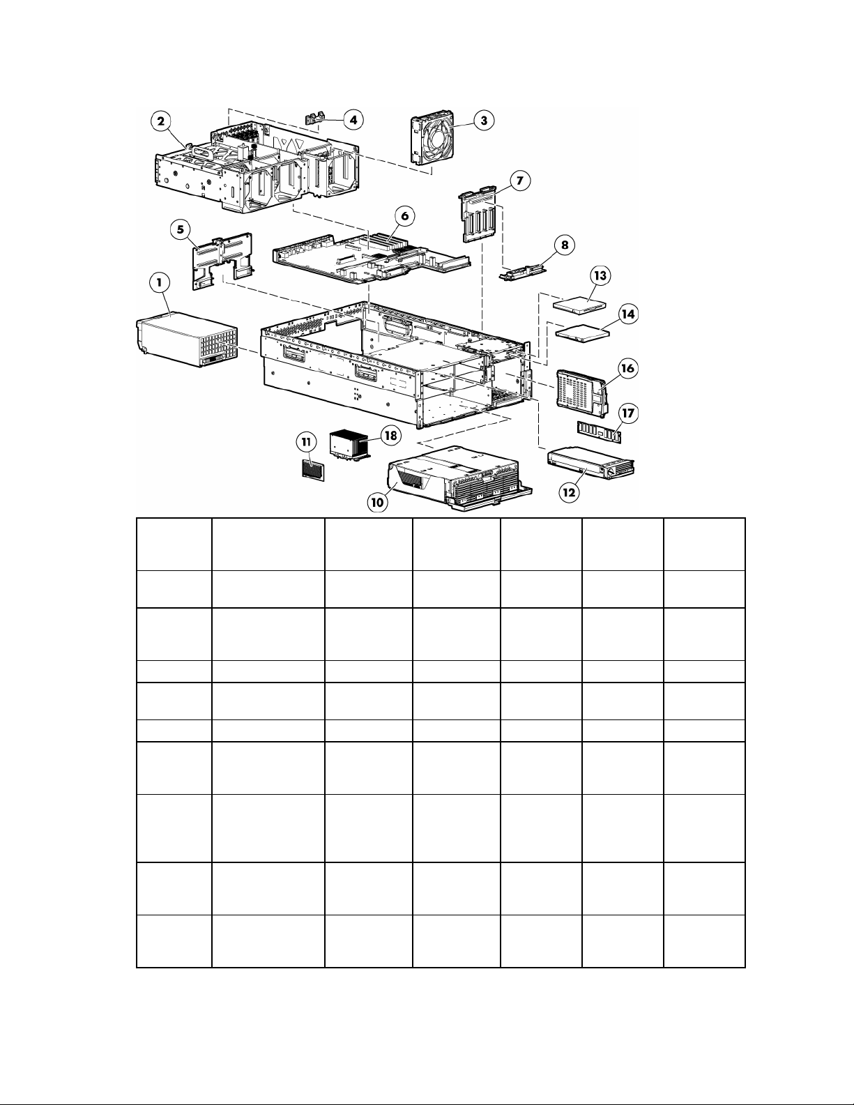
System components
Item Description
—
1
2 System cage — — — — —
3
— Boards — — — — —
4
5
6
7
System
components
Power supply,
910–1300 W
Fan 120 mm, hotplug
PCI-X Hot Plug
switch
Memory
backplane,
ProLiant DL580
G3 Server
System board,
ProLiant DL580
G3 Server
SCSI backplane,
ProLiant DL580
G3 Server
Original
assembly part
number
— — — — —
337867001‡ See
requirement
364517-001 — 374552-001 — Yes
011077001‡ See
requirement
012101001‡ See
requirement
012092001‡ See
requirement
012104001‡ See
requirement
Modified
assembly part
number
337867-501
011077-501
012101-501
012092-501
012104-501
Original
spare part
number
364360001‡ See
requirement
230981001‡ See
requirement
376471001‡ See
requirement
376468001‡ See
requirement
376474001‡ See
requirement
Modified
spare part
number
406421-001 Yes
411796-001 Yes
412327-001 Yes
412324-001 No
412328-001 Yes
Customer self
repair
Illustrated parts catalog 8
Page 9

Item Description
8
9
10
11
12
— Media devices — — — — —
13
14 DVD drive, 8x
15
— Hard drives — — — — —
16
—
—
—
—
—
—
Media board
(CD/DVD/diskette)
Power backplane,
ProLiant DL580
G3 Server *
Processor module
assembly, ProLiant
DL580 G3 Server
Processor Power
Module
Memory board,
ProLiant Dl580 G3
Server
Diskette drive, 3.5
in
DVD/CD-RW drive * 294766-
SCSI Ultra320
universal hot-plug
hard drive
a) 36.4 GB,
15,000 rpm *
b) 72.8 GB,
10,000 rpm *
c) 72.8 GB,
15,000 rpm *
d) 146.8 GB,
10,000 rpm *
e) 146.8 GB,
15,000 rpm *
f) 300 GB,
10,000 rpm *
Original
assembly part
number
012207001‡ See
requirement
012110001‡ See
requirement
012095001‡ See
requirement
367240-001 —
012098001‡ See
requirement
263394001‡ See
requirement
1680039D1/935‡
See
requirement
9D1/9D2‡
See
requirement
— — — — —
271837016‡ See
requirement
271837008‡ See
requirement
271837018‡ See
requirement
271837010‡ See
requirement
281837028‡ See
requirement
271837001‡ See
requirement
Modified
assembly part
number
012207-501
012110-501
012095-501
012825-001
263394-002
395910-001
383696-002
404670-008
404670-003
404670-007
404670-002
404670-006
404670-001
Original
spare part
number
376477001‡ See
requirement
376476001‡ See
requirement
376469001‡ See
requirement
370718001‡ See
requirement
376470001‡ See
requirement
263394002‡ See
requirement
395910001‡ See
requirement
337273001‡ See
requirement
289241001‡ See
requirement
289042001‡ See
requirement
289243001‡ See
requirement
289044001‡ See
requirement
347779001‡ See
requirement
351126001‡ See
requirement
Modified
spare part
number
416422-001 Yes
411795-001 No
412325-001 Yes
— Yes
410188-001 Yes
399396-001 Yes
397928-001 Yes
399959-001 Yes
404714-001 Yes
404709-001 Yes
404713-001 Yes
404708-001 Yes
404712-001 Yes
404701-001 Yes
Customer self
repair
Illustrated parts catalog 9
Page 10

Item Description
—
—
—
— Memory — — — — —
17
— a) 512 MB *
— b) 1 GB *
—
—
— e) 4 GB *
—
18
—
—
—
—
—
—
g) 72-GB SAS
drive, 10,000 rpm
*
h) 36-GB SAS
drive, 10,000 rpm
*
i) 60-GB SATA
drive, 5,400 rpm
*
DIMM, PC2-3200,
DDR2
c) 2 GB (singlerank) *
d) 2 GB (dualrank) *
Processor
assemblies
Processor
assemblies
a) Intel® 3.33GHz Xeon™ 8 MB
*
b) Intel® 3.00GHz Xeon™ 8 MB
*
c) Intel® 2.83GHz Xeon™ 4 MB
*
d) Intel® 3.66GHz Xeon™ 1 MB
*
e) Intel® 3.16GHz Xeon™ 1 MB
*
f) Intel® 2.66-GHz
Xeon™ 1 MBx2
dual core *
Original
assembly part
number
375696-002 — 376597-001 — Yes
375696-001 — 376596-001 — Yes
390158-001 — 382264-001 — Yes
— — — — —
345112051‡ See
requirement
345113051‡ See
requirement
345114061‡ See
requirement
345114051‡ See
requirement
345115061‡ See
requirement
— — — — —
— — — — —
376660-001 — 379982-001 — Yes
376660-002 — 379981-001 — Yes
376661-001 — 379980-001 — Yes
376659-002 — 389027-001 — Yes
376659-001 — 377840-001 — Yes
399752-001 — 399954-001 — Yes
Modified
assembly part
number
345112-851
345113-851
345114-861
345114-851
345115-861
Original
spare part
number
359241001‡ See
requirement
359242001‡ See
requirement
359243001‡ See
requirement
378021001‡ See
requirement
379984001‡ See
requirement
Modified
spare part
number
413384-001 Yes
413385-001 Yes
413386-001 Yes
413387-001 Yes
413388-001 Yes
Customer self
repair
Illustrated parts catalog 10
Page 11

Item Description
—
19
— Cables — — — — —
20
—
—
—
21
—
—
— Options — — — — —
22
23
24
25
26
27
28
29
g) Intel® 3.00GHz Xeon™ 2
MBx2 dual core*
Processor blanks
(two)
Cable kit, data,
ProLiant DL580
G3 Server *
a) Cable
assembly, USB
b) Cable
assembly, power
switch
c) Cable assembly,
PCI-X Hot Plug
switch board
SAS hard drive
cable kit *
a) SAS cable
assembly
b) SAS power
cable
Battery-Backed
Write Cache
battery housing *
Battery-Backed
Write Cache
battery *
Cache board, 128
MB *
PCI Express x4
mezzanine board
*
PCI Express x8
mezzanine board
*
PCI-X Hot Plug
mezzanine board
*
PCI-X Hot Plug
basket assembly *
SAS backplane,
ProLiant DL580
G3 Server *
Original
assembly part
number
399755-001 — 399955-001 — Yes
392523-001 — 406056-001 — Yes
— — 376478-001 — Yes
346187-001 — — — Yes
367602-001 — — — Yes
224999-003 — — — Yes
— — 393535-001 — Yes
361316-002 — — — Yes
379196-001 — — — Yes
338173-001 — 349989-001 — Yes
274779-001 — 307132-001 — Yes
012304-001 — 351518-001 — Yes
012450001‡ See
requirement
012743001‡ See
requirement
012447001‡ See
requirement
375192-001 —
012564001‡ See
requirement
Modified
assembly part
number
012450-501
012743-501
012447-501
012564-501
Original
spare part
number
376473001‡ See
requirement
390347001‡ See
requirement
376472001‡ See
requirement
393784001‡ See
requirement
376475001‡ See
requirement
Modified
spare part
number
411792-001 Yes
411793-001 Yes
411791-001 Yes
— Yes
411794-001 Yes
Customer self
repair
Illustrated parts catalog 11
Page 12

Item Description
30
SAS array
Original
assembly part
number
012335-001 — 370855-001 — Yes
Modified
assembly part
number
Original
spare part
number
Modified
spare part
number
Customer self
repair
controller board *
31
SAS array cache
011773-002 — 309522-001 — Yes
board (with
battery) *
32
SAS/SATA hard
376383-001 — 392613-001 — Yes
drive blank *
— Miscellaneous — — — — —
33
Battery, 3V,
166899-001 — 153009-001 — Yes
Lithium *
34
Power cord, AC
287485-002 — 391097-001 — Yes
line, C14-C19 *
35
Power cord, AC
178968-001 — 237457-001 — Yes
line, 5–15P *
36
Rack mount kit,
374503-001 — 377839-001 — Yes
universal *
* not shown
‡REQUIREMENT:
For Customers in the EU only.
The use of the Original Spare part is regulated by RoHS legislation§.
If your unit contains a part that is labelled with the Modified Spare number, the Modified Spare must be ordered as
the replacement part in the EU.
If your unit contains a part that is labelled with the Original Spare number, please order the Original Spare as the
replacement part in the EU. In this case either the Original Spare or the Modified Spare may be shipped which will
not affect performance or functionality of the unit.
§Directive 2002/95/EC restricts the use of lead, mercury, cadmium, hexavalent chromium, PBBs and PBDEs in
electronic products.
Illustrated parts catalog 12
Page 13

Removal and replacement procedures
In this section
Required tools........................................................................................................................................ 13
Safety considerations.............................................................................................................................. 14
Preparation procedures........................................................................................................................... 14
Removing the front bezel......................................................................................................................... 18
Removing a media drive blank ................................................................................................................ 19
Removing a media drive ......................................................................................................................... 19
Removing the processor module............................................................................................................... 20
Removing a processor............................................................................................................................. 22
Removing a PPM.................................................................................................................................... 25
Removing a PCI latch.............................................................................................................................. 26
Removing a PCI retaining clip.................................................................................................................. 27
Removing the PCI-X Hot Plug basket.......................................................................................................... 28
Removing a non-hot-plug expansion board................................................................................................ 28
Removing the PCI-X Hot Plug mezzanine option ......................................................................................... 29
Removing the PCI Express mezzanine option............................................................................................. 30
Recovering data from the BBWC.............................................................................................................. 30
Removing the BBWC battery pack............................................................................................................ 31
Removing the BBWC cache module ......................................................................................................... 32
Removing the system board..................................................................................................................... 32
Removing the system battery.................................................................................................................... 35
Removing the media board ..................................................................................................................... 37
Removing the SCSI backplane ................................................................................................................. 37
Removing the power backplane ............................................................................................................... 39
Removing the memory backplane............................................................................................................. 39
Removing a hard drive blank................................................................................................................... 40
Removing a hot-plug SCSI hard drive ....................................................................................................... 40
Removing a hot-plug SAS hard drive ........................................................................................................ 41
Removing the SAS-SATA hard drive cage.................................................................................................. 42
Removing the SAS-SATA backplane ......................................................................................................... 46
Removing a PCI-X Hot Plug expansion board............................................................................................. 47
Removing a power supply blank ..................................................................................................
Removing a redundant hot-plug power supply ........................................................................................... 48
Replacing hot-plug fans........................................................................................................................... 49
Memory overview .................................................................................................................................. 50
............ 48
Required tools
You need the following items for some procedures:
• Torx T-15 screwdriver (provided with the server ("Rear panel components" on page 73))
• Phillips screwdriver
Removal and replacement procedures 13
Page 14

•
Flathead screwdriver
• Diagnostics Utility
Safety considerations
Before performing service procedures, review all the safety information.
Preventing electrostatic discharge
To prevent damaging the system, be aware of the precautions you need to follow when setting up the
system or handling parts. A discharge of static electricity from a finger or other conductor may damage
system boards or other static-sensitive devices. This type of damage may reduce the life expectancy of the
device.
To prevent electrostatic damage:
• Avoid hand contact by transporting and storing products in static-safe containers.
• Keep electrostatic-sensitive parts in their containers until they arrive at static-free workstations.
• Place parts on a grounded surface before removing them from their containers.
• Avoid touching pins, leads, or circuitry.
• Always be properly grounded when touching a static-sensitive component or assembly.
Server warnings and cautions
Before installing a server, be sure that you understand the following warnings and cautions.
WARNING: To reduce the risk of electric shock or damage to the equipment:
• Do not disable the power cord grounding plug. The grounding plug is an important
safety feature.
• Plug the power cord into a grounded (earthed) electrical outlet that is easily
accessible at all times.
• Unplug the power cord from the power supply to disconnect power to the equipment.
• Do not route the power cord where it can be walked on or pinched by items placed
against it. Pay particular attention to the plug, electrical outlet, and the point where
the cord extends from the server.
WARNING: To reduce the risk of personal injury from hot surfaces, allow the drives and
the internal system components to cool before touching them.
CAUTION: Do not operate the server for long periods with the access panel open or removed. Operating
the server in this manner results in improper airflow and improper cooling that can lead to thermal damage.
Preparation procedures
To access some components and perform certain service procedures, perform one or more of the
following procedures:
• Extend the server from the rack ("Extending the server from the rack" on page 15).
If you are performing service procedures in an HP, Compaq branded, telco, or third-party rack
cabinet, you can use the locking feature of the rack rails to support the server and gain access to
internal components.
For more information about telco rack solutions, refer to the RackSolutions.com website
(http://www.racksolutions.com/hp
).
Removal and replacement procedures 14
Page 15
•
Power down the server (on page 16).
If you must remove a server from a rack or a non-hot-plug component from a server, power down the
server.
• Remove the server from the rack (on page 16).
If the rack environment, cabling configuration, or the server location in the rack makes it difficult to
service the unit, remove the server from the rack.
• Remove the access panel ("Removing the access panel" on page 17).
If you are servicing internal components, remove the access panel.
• Remove the system cage ("Removing the system cage" on page 17).
If you must remove the system board, power backplane, or the BBWC, remove the system cage.
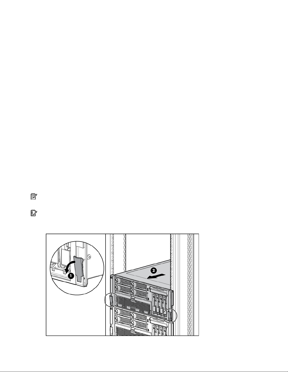
Extending the server from the rack
The design of the server enables you to access several components through the front of the server.
Installing or accessing the following components will not require extending the server from the rack:
• Processors
• PPMs
• Memory boards
• DIMMs
• Media drive
• Diskette drive
• Hard drives
To extend the server from the rack:
1. Release the two levers on the lower outside corners of the rack.
NOTE: If the server is in a rack and in the shipping configuration, remove the two shipping screws directly
behind the levers and the two shipping screws on the rails in the rear of the server.
IMPORTANT: If the server is installed in a telco rack, remove the server from the rack to access internal
components.
2. Extend the server on the rack rails until the server rail-release latches engage.
Removal and replacement procedures 15
Page 16
WARNING: To reduce the risk of personal injury or equipment damage, be sure that the
rack is adequately stabilized before extending a component from the rack.
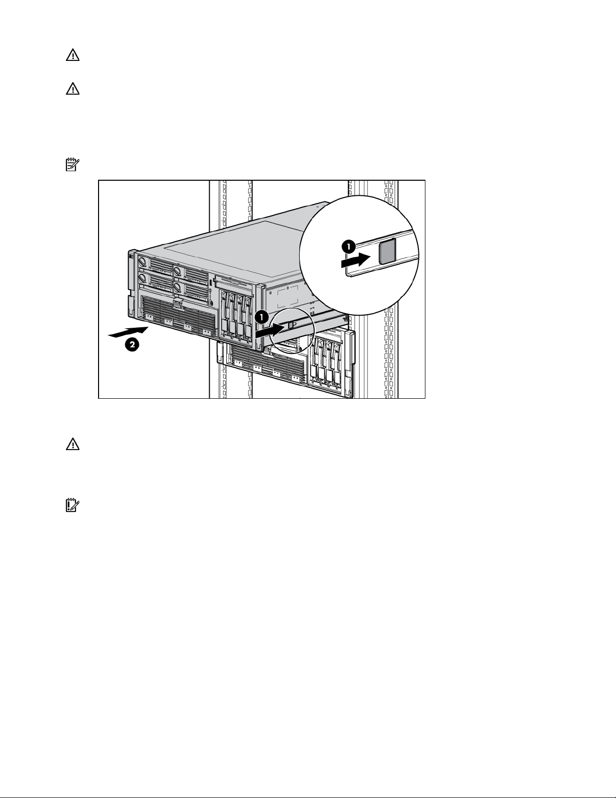
WARNING: To reduce the risk of personal injury, be careful when pressing the server
rail-release latches and sliding the server into the rack. The sliding rails could pinch your
fingers.
3. After performing the installation or maintenance procedure, slide the server back into the rack by
pressing the server rail-release latches.
NOTE: The release latches will lock into place when the rails are fully extended.
Power down the server
WARNING: To reduce the risk of personal injury, electric shock, or damage to the
equipment, remove the power cord to remove power from the server. The front panel
Power On/Standby button does not completely shut off system power. Portions of the
power supply and some internal circuitry remain active until AC power is removed.
IMPORTANT: If installing a hot-plug device, it is not necessary to power down the server.
1. Shut down the OS as directed by the OS documentation.
2. Press the Power On/Standby button to place the server in standby mode. When the server enters
standby power mode, the system power LED changes to amber.
3. Disconnect the power cords.
The system is now without power.
Remove the server from the rack
To remove the server from an HP, Compaq branded, telco, or third-party rack:
1. Power down the server (on page 16).
2. Extend the server from the rack ("Extending the server from the rack" on page 15).
3. Disconnect the cabling and remove the server from the rack. For more information, refer to the
documentation that ships with the rack mounting option.
4. Place the server on a sturdy, level surface.
Removal and replacement procedures 16
Page 17
Removing the access panel
WARNING: To reduce the risk of personal injury from hot surfaces, allow the drives and
the internal system components to cool before touching them.
CAUTION: Do not operate the server for long periods with the access panel open or removed. Operating
the server in this manner results in improper airflow and improper cooling that can lead to thermal damage.
IMPORTANT: When removing the access panel to view QuickFind diagnostic LEDs ("QuickFind diagnostic
display LEDs" on page 78), leave the server powered on. The QuickFind diagnostic LEDs are cleared when
the server is powered off.
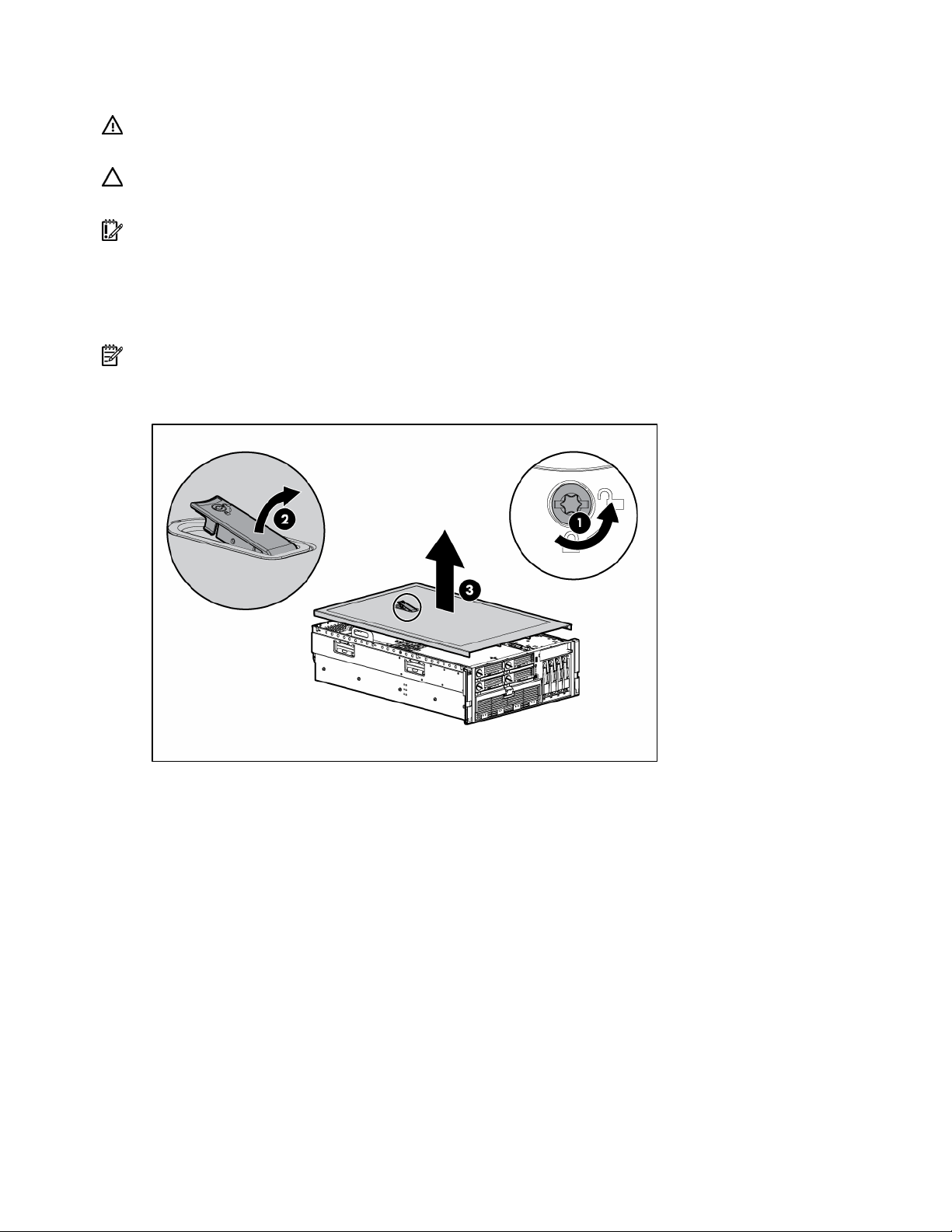
1. Extend the server from the rack, if applicable ("Extending the server from the rack" on page 15).
2. If the locking latch is locked, use a Torx T-15 screwdriver to unlock the latch.
NOTE: The T-15 Torx screwdriver is shipped with the server and can be located on the rear panel ("Rear
panel components" on page 73).
3. Lift up on the hood latch, and remove the access panel.
4. After installing hardware options, replace the access panel. Be sure that the panel is securely locked
into place before powering up the server.
Removing the system cage
Installing or accessing some options in the server may require removing the system cage. Refer to the
instructions for each individual option to determine if removing the system cage is necessary.
To remove the system cage:
1. Power down the server, if applicable ("Power down the server" on page 16).
2. Extend the server from the rack, if applicable ("Extending the server from the rack" on page 15).
3. Remove the access panel ("Removing the access panel" on page 17).
4. Remove all expansion boards and expansion slot covers.
5. Remove the PCI-X Hot Plug basket, if applicable.
6. Disconnect the hot-plug board cable from the PCI-X Hot Plug mezzanine board, if applicable.
7. Remove all system fans ("Replacing hot-plug fans" on page 49).
Removal and replacement procedures 17
Page 18
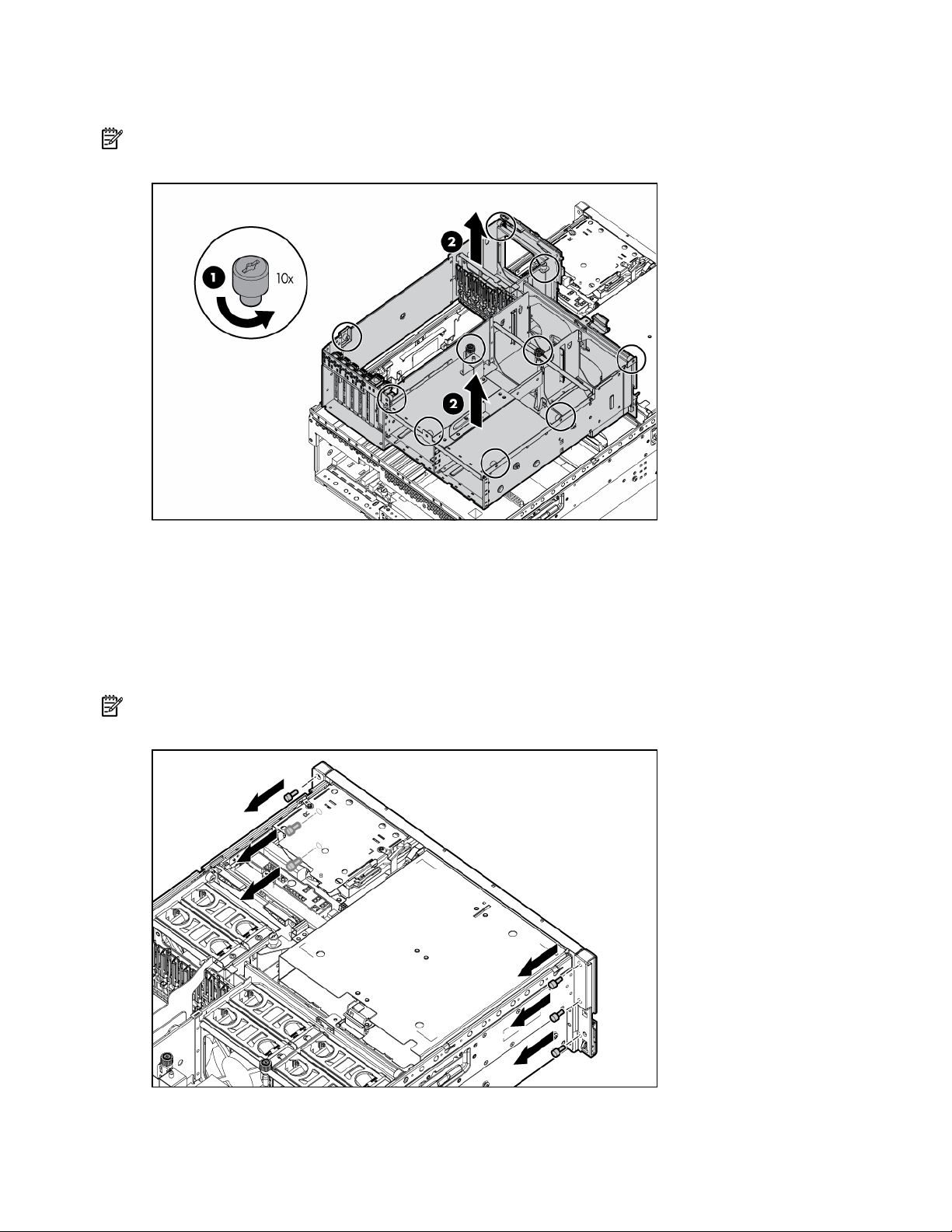
8.
Remove all power supplies ("Removing a redundant hot-plug power supply" on page 48).
9. Loosen the thumbscrews, and lift the system cage from the server.
NOTE: The T-15 Torx screwdriver can be used to loosen the thumbscrews. The T-15 Torx screwdriver is
shipped with the server and can be located on the rear panel ("Rear panel components" on page 73).
Removing the front bezel
1. Power down the server (on page 16).
2. Extend the server from the rack ("Extending the server from the rack" on page 15).
3. Remove the access panel ("Removing the access panel" on page 17).
4. Using the T-15 Torx screwdriver, remove the three screws on each side of the front bezel.
NOTE: The T-15 Torx screwdriver is shipped with the server and can be located on the rear panel ("Rear
panel components" on page 73).
5. Release the two levers on the lower outside corners of the rack.
Removal and replacement procedures 18
Page 19
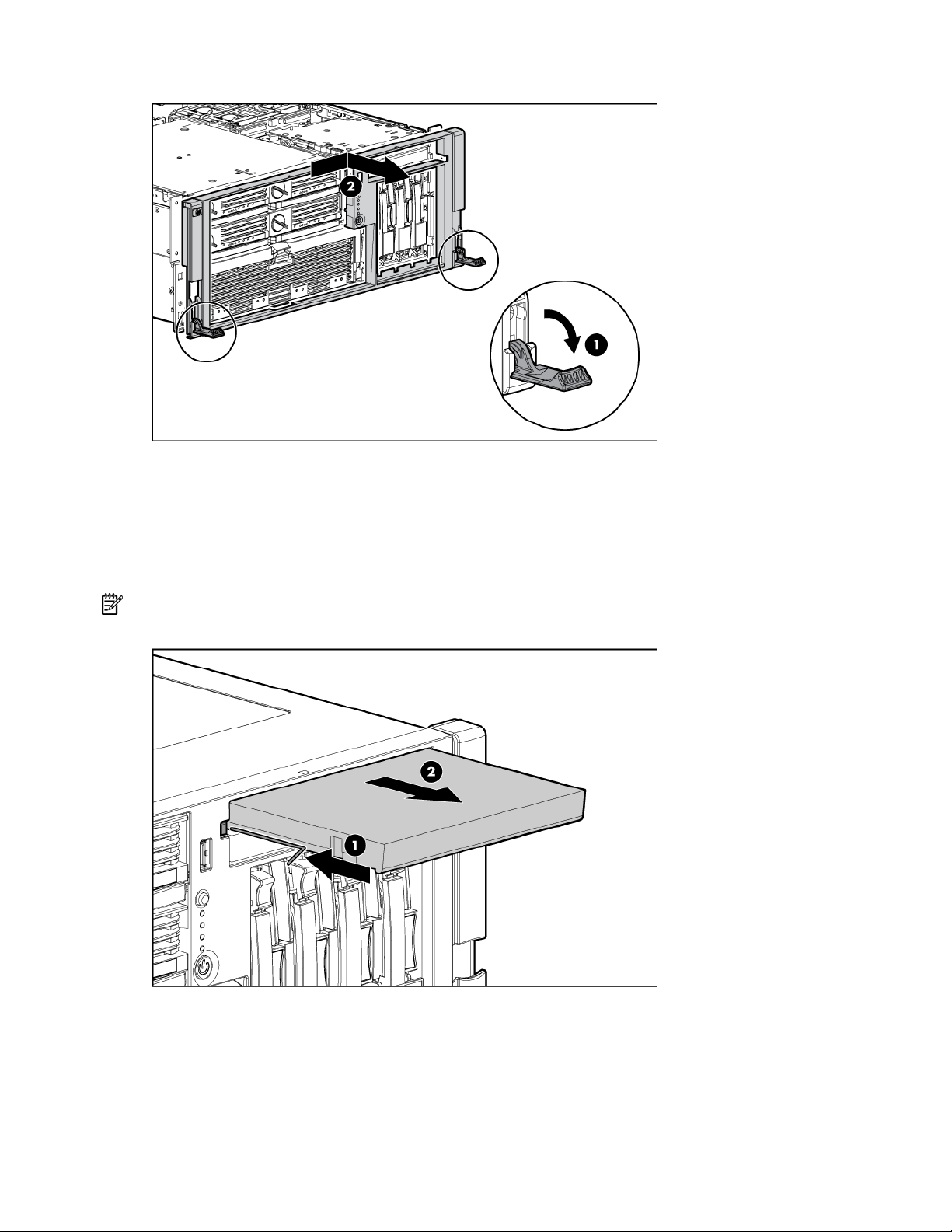
6.
Slide the bezel to the right, and detach the bezel from the server.
To replace the component, reverse the removal procedure.
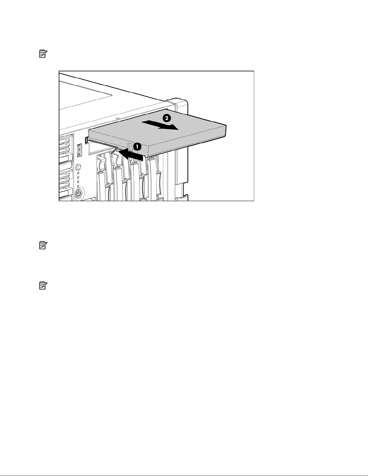
Removing a media drive blank
1. Power down the server (on page 16).
2. Use the T-15 Torx screwdriver to eject the drive blank, and pull the drive blank out of the server.
NOTE: The T-15 Torx screwdriver is shipped with the server and can be located on the rear panel ("Rear
panel components" on page 73).
To replace the component, reverse the removal procedure.
Removing a media drive
To remove the DVD drive, optional diskette drive, or optional CD-RW drive:
Removal and replacement procedures 19
Page 20
1.
Power down the server (on page 16).
2. Use the T-15 Torx screwdriver to eject the drive, and pull the drive out of the server.
NOTE: The T-15 Torx screwdriver is shipped with the server and can be located on the rear panel ("Rear
panel components" on page 73).
To replace the component, reverse the removal procedure.
Removing the processor module
NOTE: Refer the section "Processor module LEDs (on page 72)" for information on the current processor
and PPM status.
1. Power down the server (on page 16).
2. Remove the shipping bracket, if applicable.
NOTE: The shipping bracket is located near the processor module lever, and is marked with an orange tab
for easy identification.
Removal and replacement procedures 20
Page 21
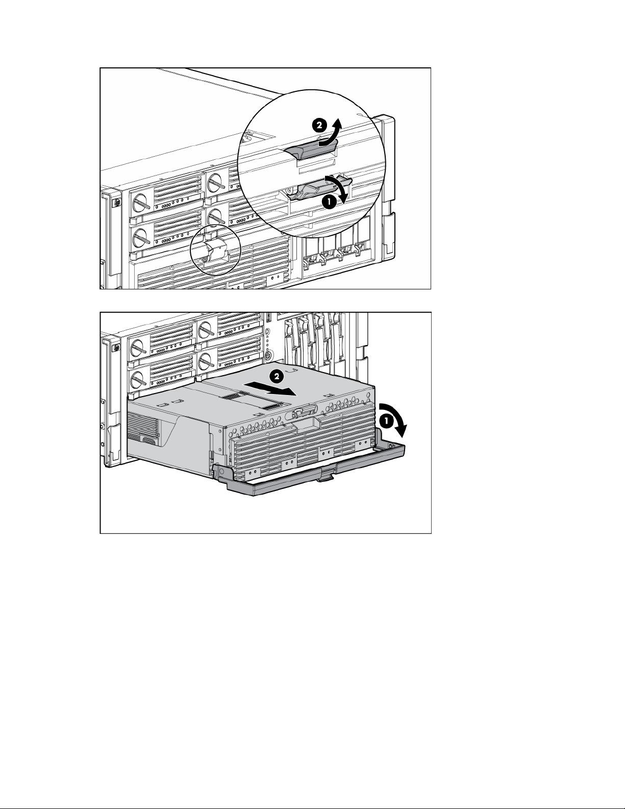
3.
Release the latches to unlock the processor module.
4. Lower the processor module lever, and pull the module out of the server.
Removal and replacement procedures 21
Page 22
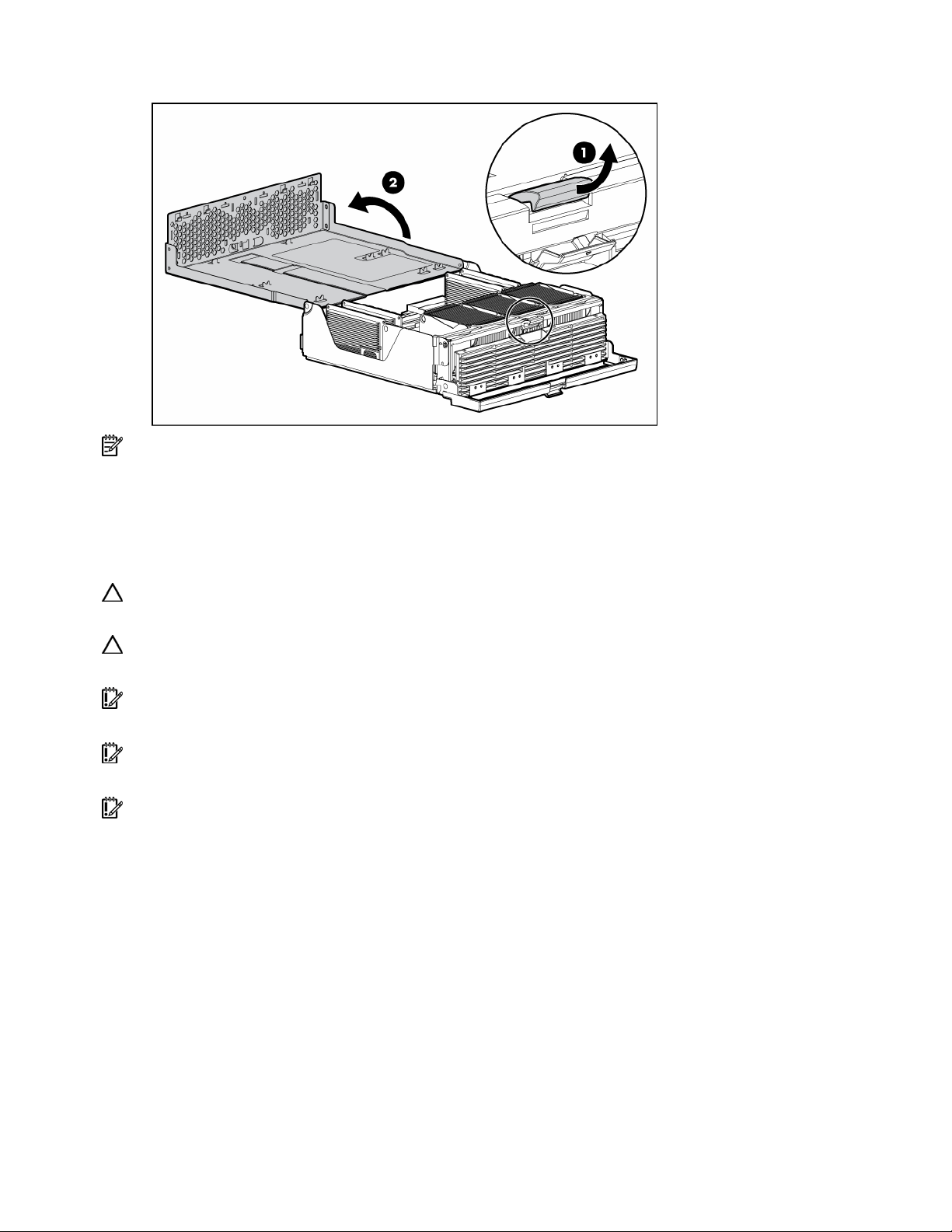
5.
Release the latch, and open the cover to expose the processors.
NOTE: To install a new processor module, remove all processors and PPMs from the processor module.
Reinstall the processors and PPMs into the replacement processor module.
To replace the component, reverse the removal procedure.
Removing a processor
CAUTION: To prevent thermal instability and damage to the server, do not separate the processor from the
heatsink. The processor, heatsink, and retaining clip make up a single assembly.
CAUTION: To prevent possible server malfunction and damage to the equipment, do not mix single- and
dual-core processors or processors with different speeds or cache sizes.
IMPORTANT: If upgrading processor speed or adding additional processors, update the system ROM
before installing the processor.
IMPORTANT: Processor socket 1 and PPM slot 1 must be populated at all times or the server does not
function properly.
IMPORTANT: Always install a PPM when you install a processor. The system fails to boot if the PPM is
missing.
1. Power down the server (on page 16).
2. Remove the processor module ("Removing the processor module" on page 20).
Removal and replacement procedures 22
Page 23
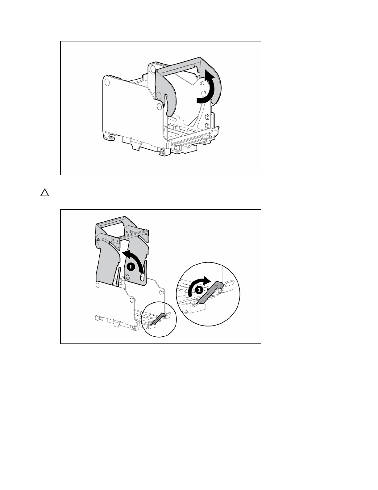
3.
Unlock the processor retaining bracket.
4. Open the processor retaining bracket, and open the processor locking lever.
CAUTION: Failure to completely open the processor locking lever prevents the processor from seating
during installation, leading to hardware damage.
5. Remove the processor.
Removal and replacement procedures 23
Page 24
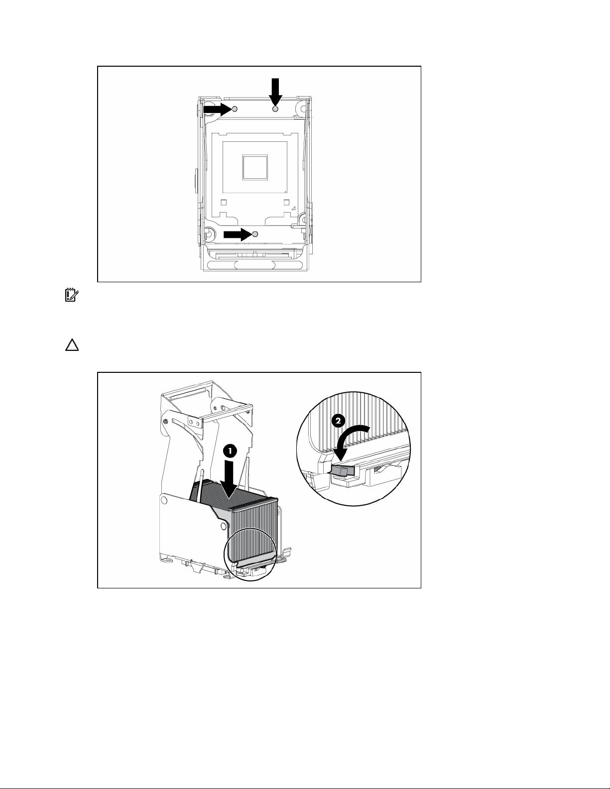
6.
Install the replacement processor assembly, if applicable.
IMPORTANT: Determine the correct processor orientation by observing the guide pins on the base of the
processor retaining bracket and the three corresponding guide slots on the processor assembly.
7. Insert the processor assembly into the processor socket, and close the locking lever.
CAUTION: To prevent possible server malfunction or damage to the equipment, be sure to completely close
the processor locking lever.
Removal and replacement procedures 24
Page 25

8.
Close and lock the processor retaining bracket.
9. Close the cover, and replace the processor module.
Removing a PPM
The server PPMs provide the proper power to each processor. Each PPM must be installed in the correct
slot for the processor.
IMPORTANT: Processor socket 1 and PPM slot 1 must be populated at all times or the server does not
function properly.
IMPORTANT: Always install a PPM when you install a processor. The system fails to boot if the PPM is
missing.
To remove a PPM:
1. Power down the server (on page 16).
2. Remove the processor module ("Removing the processor module" on page 20).
Removal and replacement procedures 25
Page 26
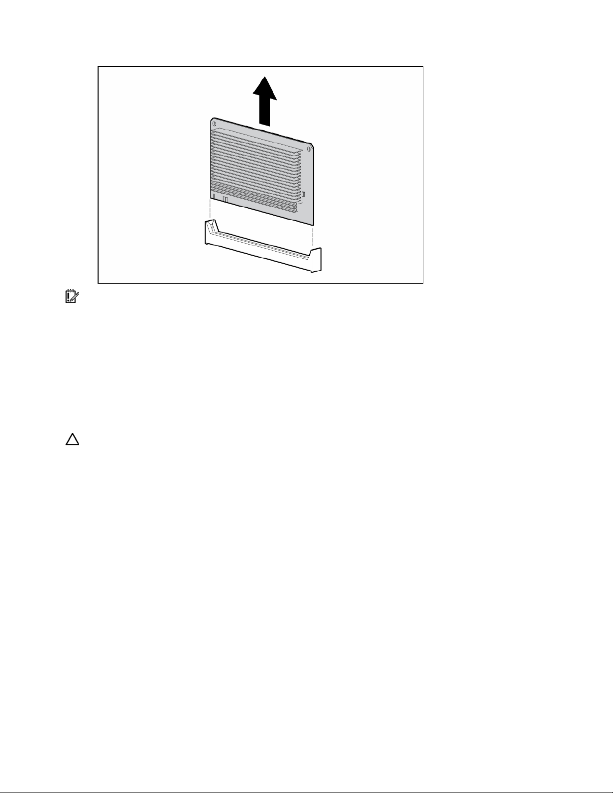
3.
Remove the PPM.
IMPORTANT: Always install a PPM when you install a processor. The system fails to boot if the
corresponding PPM is missing.
To replace the component, reverse the removal procedure.
Removing a PCI latch
1. Power down the server (on page 16).
2. Extend or remove the server from the rack ("Remove the server from the rack" on page 16).
3. Remove the access panel ("Removing the access panel" on page 17).
CAUTION: To prevent improper cooling and thermal damage, do not operate the server unless all
expansion slots have either an expansion slot cover or an expansion board installed.
4. Open the latch.
5. Remove the expansion board from the slot, if installed ("Removing a PCI-X Hot Plug expansion
board" on page 47).
6. Remove the expansion slot cover from the slot, if installed.
Removal and replacement procedures 26
Page 27
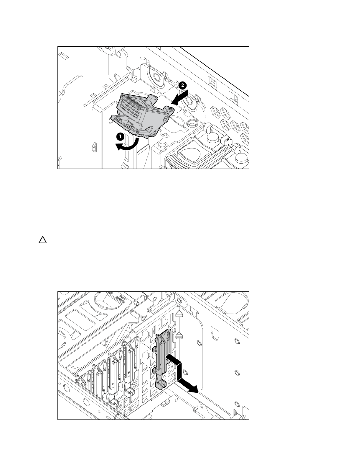
7.
Remove the PCI latch by pushing up on the clear plastic piece of the PCI latch that extends below the
chassis under the latch.
To replace the component, reverse the removal procedure.
Removing a PCI retaining clip
1. Power down the server (on page 16).
2. Extend or remove the server from the rack ("Remove the server from the rack" on page 16).
3. Remove the access panel ("Removing the access panel" on page 17).
CAUTION: To prevent improper cooling and thermal damage, do not operate the server unless all
expansion slots have either an expansion slot cover or an expansion board installed.
4. Open the PCI latch, and unlock the PCI retaining clip.
5. Remove the expansion board from the slot, if installed ("Removing a PCI-X Hot Plug expansion
board" on page 47).
6. Remove the PCI retaining clip.
Removal and replacement procedures 27
Page 28
To replace the component, reverse the removal procedure.
Removing the PCI-X Hot Plug basket
1. Power down the server (on page 16).
2. Extend or remove the server from the rack ("Remove the server from the rack" on page 16).
3. Remove the access panel ("Removing the access panel" on page 17).
CAUTION: To prevent improper cooling and thermal damage, do not operate the server unless all
expansion slots have either an expansion slot cover or an expansion board installed.
4. Remove the expansion board from the slot, if installed ("Removing a PCI-X Hot Plug expansion
board" on page 47).
5. Remove the PCI-X Hot Plug basket ("Removing the PCI-X Hot Plug basket" on page 28).
To replace the component, reverse the removal procedure.
Removing a non-hot-plug expansion board
1. Power down the server (on page 16).
2. Extend or remove the server from the rack ("Remove the server from the rack" on page 16).
3. Remove the access panel ("Removing the access panel" on page 17).
4. Disconnect any required internal or external cables from the expansion board.
5. Open the PCI latch.
6. Unlock the retaining clip.
Removal and replacement procedures 28
Page 29
7.
Remove the expansion board.
To replace the component, reverse the removal procedure.
Removing the PCI-X Hot Plug mezzanine option
1. Power down the server (on page 16).
2. Extend or remove the server from the rack ("Remove the server from the rack" on page 16).
3. Remove the access panel ("Removing the access panel" on page 17).
4. Remove the expansion boards from slots 1 and 2.
5. Remove the expansion boards from slots 3 and 4, if installed, to gain access to the mezzanine
board.
6. Remove the PCI-X Hot Plug basket ("Removing the PCI-X Hot Plug basket" on page 28).
7. Disconnect the cable from the PCI-X Hot Plug mezzanine board.
8. Loosen the thumbscrews, and lift the mezzanine board from the server.
Removal and replacement procedures 29
Page 30

CAUTION: To prevent improper cooling and thermal damage, do not operate the server unless all
expansion slots have either an expansion slot cover or an expansion board installed.
To replace the component, reverse the removal procedure.
Removing the PCI Express mezzanine option
1. Power down the server (on page 16).
2. Extend or remove the server from the rack ("Remove the server from the rack" on page 16).
3. Remove the access panel ("Removing the access panel" on page 17).
4. Remove the expansion boards from slots 1 and 2.
5. Remove the expansion boards from slots 3 and 4, if installed, to gain access to the mezzanine
board.
6. Loosen the thumbscrews, and lift the mezzanine board from the server.
CAUTION: To prevent improper cooling and thermal damage, do not operate the server unless all
expansion slots have either an expansion slot cover or an expansion board installed.
To replace the component, reverse the removal procedure.
Recovering data from the BBWC
If the server fails, you can recover any data temporarily trapped in the BBWC by using the following
procedure.
CAUTION: Before starting this procedure, read the information about protecting against electrostatic
discharge ("Preventing electrostatic discharge" on page 14).
1. Perform one of the following:
• Set up a recovery server station using an identical server model. Do not install any internal drives
or BBWC in this server. (This option is preferred.)
• Find a server that has enough empty drive bays to accommodate all the drives from the failed
server and that meets all the other requirements for drive and array migration.
Removal and replacement procedures 30
Page 31

2.
Power down the failed server ("Power down the server" on page 16). If any data is trapped in the
cache module, the amber LED on the module ("BBWC LEDs" on page 87) blinks every 15 seconds.
CAUTION: Do not detach the cable that connects the battery pack to the cache module. Detaching the
cable causes any unsaved data in the cache module to be lost.
3. Transfer the hard drives from the failed server to the recovery server station.
4. Remove the BBWC cache module and battery pack from the failed server.
5. Perform one of the following:
• Install the BBWC into an empty BBWC DIMM socket on the system board of the recovery server.
• Install the BBWC into an empty BBWC DIMM socket on any Smart Array 641 or 642 controller
in the recovery server.
6. Power up the recovery server. A 1759 POST message appears, stating that valid data was flushed
from the cache. This data is now stored on the drives in the recovery server. You can now transfer
the drives (and controller, if one was used) to another server.
Removing the BBWC battery pack
1. Power down the server (on page 16).
2. Extend or remove the server from the rack ("Remove the server from the rack" on page 16).
3. Remove the access panel ("Removing the access panel" on page 17).
4. Remove the system cage ("Removing the system cage" on page 17).
CAUTION: To prevent a server malfunction or damage to the equipment, do not add or remove the battery
pack while an array capacity expansion, RAID level migration, or stripe size migration is in progress.
CAUTION: After the server is powered down, wait 15 seconds and then check the amber LED before
unplugging the cable from the cache module. If the amber LED blinks after 15 seconds, do not remove the
cable from the cache module. The cache module is backing up data, and data is lost if the cable is
detached.
5. Remove the BBWC battery pack.
To replace the component, reverse the removal procedure.
Removal and replacement procedures 31
Page 32

IMPORTANT: The battery pack might have a low charge when installed. In this case, a POST error
message is displayed when the server is powered up, indicating that the battery pack is temporarily
disabled. No action is necessary on your part. The internal circuitry automatically recharges the batteries
and enables the battery pack. This process might take up to four hours. During this time, the cache module
functions properly, but without the performance advantage of the battery pack.
NOTE: The data protection and the time limit also apply if a power outage occurs. When power is restored
to the system, an initialization process writes the preserved data to the hard drives.
Removing the BBWC cache module
1. Power down the server (on page 16).
2. Extend or remove the server from the rack ("Remove the server from the rack" on page 16).
3. Remove the access panel ("Removing the access panel" on page 17).
4. Remove the system cage ("Removing the system cage" on page 17).
CAUTION: To prevent a server malfunction or damage to the equipment, do not add or remove the battery
pack while an array capacity expansion, RAID level migration, or stripe size migration is in progress.
CAUTION: After the server is powered down, wait 15 seconds and then check the amber LED before
unplugging the cable from the cache module. If the amber LED blinks after 15 seconds, do not remove the
cable from the cache module. The cache module is backing up data, and data is lost if the cable is
detached.
5. Open the latches, and remove the BBWC cache module.
6. Disconnect the cable from the cache module.
To replace the component, reverse the removal procedure.
Removing the system board
CAUTION: Only authorized technicians trained by HP should attempt to remove the system board. If you
believe the system board requires replacement, contact HP Technical Support before proceeding.
Removal and replacement procedures 32
Page 33

IMPORTANT: HP recommends troubleshooting the system using port 85 codes before replacing the system
board. Refer to "Troubleshooting the system using port 85 codes (on page 64)" for a list of codes and
troubleshooting procedures.
1. Power down the server (on page 16).
2. Remove all media drives ("Removing a media drive" on page 19) and media drive blanks
("Removing a media drive blank" on page 19).
3. Remove all hard drives ("Removing a hot-plug SCSI hard drive" on page 40, "Removing a hot-plug
SAS hard drive" on page 41) and hard drive blanks ("Removing a hard drive blank" on page 40).
4. Remove all memory boards ("Removing a memory board" on page 58, "Removing a memory board
(non-hot-plug)" on page 57) and memory board blanks.
5. Remove the processor module ("Removing the processor module" on page 20).
6. Extend or remove the server from the rack ("Remove the server from the rack" on page 16).
7. Remove the access panel ("Removing the access panel" on page 17).
8. Remove the media board ("Removing the media board" on page 37).
9. Remove the SCSI backplane ("Removing the SCSI backplane" on page 37).
10. Remove all system fans ("Replacing hot-plug fans" on page 49).
11. Remove all expansion boards ("Removing a non-hot-plug expansion board" on page 28, "Removing
a PCI-X Hot Plug expansion board" on page 47).
12. Remove the PCI-X Hot Plug basket ("Removing the PCI-X Hot Plug basket" on page 28), if installed.
13. Disconnect the cable from the PCI-X Hot Plug mezzanine board, if installed.
14. Remove the system cage ("Removing the system cage" on page 17).
15. Unlock the latch and open the lever.
Removal and replacement procedures 33
Page 34

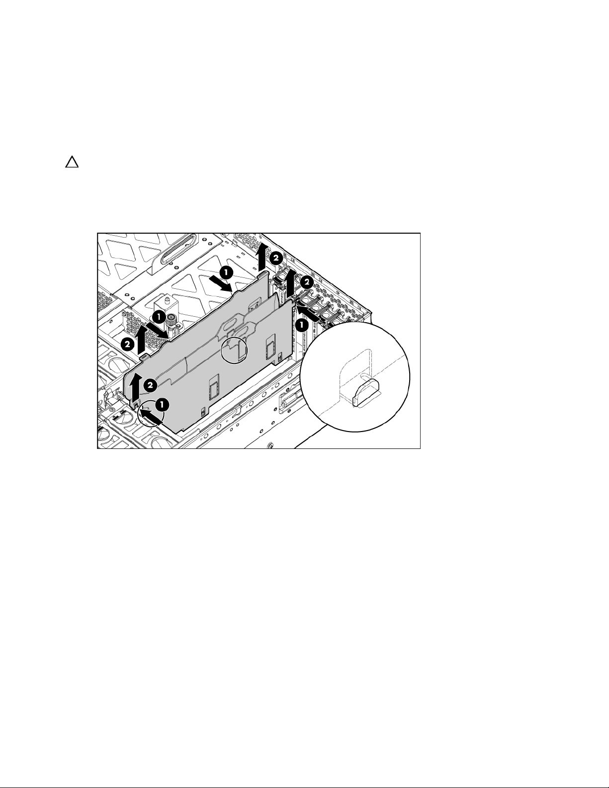
16.
Using the lever, lift the system board slightly, and slide the system board out through the back of the
server.
IMPORTANT: If replacing the system board or clearing NVRAM, you must re-enter the server serial number
through RBSU ("Re-entering the server serial number and product ID" on page 34).
To replace the component, reverse the removal procedure.
Re-entering the server serial number and product ID
After you replace the system board, you must re-enter the server serial number and the product ID.
1. During the server startup sequence, press the F9 key to access RBSU.
2. Select the Advanced Options menu.
3. Select Serial Number. The following warning is displayed:
Warning: The serial number should ONLY be modified by qualified service
personnel. This value should always match the serial number located on
the chassis.
4. Press the Enter key to clear the warning.
5. Enter the serial number.
6. Select Product ID. The following warning is displayed.
Warning: The Product ID should ONLY be modified by qualified service
personnel. This value should always match the Product ID located on the
chassis.
7. Enter the product ID and press the Enter key.
8. Press the Escape key to close the menu.
9. Press the Escape key to exit RBSU.
Removal and replacement procedures 34
Page 35

10.
Press the F10 key to confirm exiting RBSU. The server will automatically reboot.
Removing the system battery
If the server no longer automatically displays the correct date and time, you might need to replace the
battery that provides power to the real-time clock. Under normal use, battery life is five to 10 years.
WARNING: The computer contains an internal lithium manganese dioxide, a vanadium
pentoxide, or an alkaline battery pack. A risk of fire and burns exists if the battery pack
is not properly handled. To reduce the risk of personal injury:
• Do not attempt to recharge the battery.
• Do not expose the battery to temperatures higher than 60°C (140°F).
• Do not disassemble, crush, puncture, short external contacts, or dispose of in fire or
water.
• Replace only with the spare designated for this product.
1. Power down the server (on page 16).
2. Extend or remove the server from the rack ("Remove the server from the rack" on page 16).
3. Remove the access panel ("Removing the access panel" on page 17).
Removal and replacement procedures 35
Page 36

4.
Locate the battery.
5. Remove the battery.
Removal and replacement procedures 36
Page 37

To replace the component, reverse the removal procedure.
Run RBSU to configure the server after replacing the battery. Refer to the HP ROM-Based Setup Utility User
Guide on the Documentation CD for more detailed information.
Removing the media board
1. Power down the server (on page 16).
2. Extend the server from the rack, if applicable ("Extending the server from the rack" on page 15).
3. Remove the access panel ("Removing the access panel" on page 17).
4. Remove all media drives ("Removing a media drive" on page 19) and media drive blanks
("Removing a media drive blank" on page 19).
5. Disconnect all cabling from the media board.
6. Loosen the thumbscrew, and slide the media board toward the front of the server to disconnect it
from the SCSI backplane.
7. Remove the media board.
To replace the component, reverse the removal procedure.
Removing the SCSI backplane
1. Power down the server (on page 16).
2. Remove all media drives ("Removing a media drive" on page 19) and media drive blanks
("Removing a media drive blank" on page 19).
3. Remove all hard drives ("Removing a hot-plug SCSI hard drive" on page 40, "Removing a hot-plug
SAS hard drive" on page 41) and hard drive blanks ("Removing a hard drive blank" on page 40).
4. Extend the server from the rack, if applicable ("Extending the server from the rack" on page 15).
5. Remove the access panel ("Removing the access panel" on page 17).
6. Disconnect all cables from the SCSI backplane.
7. Remove the media board ("Removing the media board" on page 37).
Removal and replacement procedures 37
Page 38

8.
Record the position of the SCSI simplex/duplex switch.
9. Lift the levers, and pull the SCSI backplane out of the server.
Removal and replacement procedures 38
Page 39

IMPORTANT: Be sure to set the SCSI simplex/duplex switch to the appropriate setting when replacing the
SCSI backplane.
To replace the component, reverse the removal procedure.
Removing the power backplane
1. Power down the server (on page 16).
2. Remove all power supplies ("Removing a redundant hot-plug power supply" on page 48) and power
supply blanks ("Removing a power supply blank" on page 48).
NOTE: If you remove or replace the primary hot-plug power supply, use the T-15 Torx screwdriver provided
with the server to remove the shipping screw. It is located just under the port-colored plastic handle of the
power supply unit.
3. Extend or remove the server from the rack ("Remove the server from the rack" on page 16).
4. Remove the access panel ("Removing the access panel" on page 17).
5. Remove the system cage ("Removing the system cage" on page 17).
6. Loosen the thumbscrew, and remove the power backplane from the server.
To replace the component, reverse the removal procedure.
Removing the memory backplane
1. Power down the server (on page 16).
2. Remove all memory boards ("Removing a memory board" on page 58, "Removing a memory board
(non-hot-plug)" on page 57).
3. Remove the processor module ("Removing the processor module" on page 20).
4. Extend or remove the server from the rack ("Remove the server from the rack" on page 16).
5. Remove the access panel ("Removing the access panel" on page 17).
Removal and replacement procedures 39
Page 40

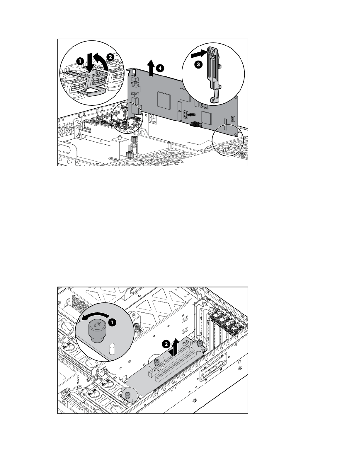
6.
Open the latch, and lift the memory backplane from the server.
To replace the component, reverse the removal procedure.
Removing a hard drive blank
CAUTION: To prevent improper cooling and thermal damage, do not operate the server unless all bays
are populated with either a component or a blank.
Remove the hard drive blank by squeezing the release buttons, and pulling the blank from the server.
To replace the component, reverse the removal procedure.
Removing a hot-plug SCSI hard drive
CAUTION: Always power down the server if the boot partition resides on the drive you are replacing or if
you are replacing the only drive in the server.
Removal and replacement procedures 40
Page 41

CAUTION: To prevent improper cooling and thermal damage, do not operate the server unless all bays
are populated with either a component or a blank.
1. Determine the status of the hard drive from the hot-plug hard drive LEDs ("Hot-plug SCSI hard drive
LEDs" on page 82, "SATA or SAS hard drive LEDs" on page 84).
2. Back up all server data on the hard drive to be removed.
3. Remove the hard drive.
To replace the component, reverse the removal procedure.
Removing a hot-plug SAS hard drive
CAUTION: Always power down the server if the boot partition resides on the drive you are replacing or if
you are replacing the only drive in the server.
CAUTION: To prevent improper cooling and thermal damage, do not operate the server unless all bays
are populated with either a component or a blank.
1. Determine the status of the hard drive from the hot-plug hard drive LEDs ("SAS and SATA hard drive
LED combinations" on page 84).
2. Back up all server data on the hard drive to be removed.
Removal and replacement procedures 41
Page 42

3.
Remove the hard drive.
Removing the SAS-SATA hard drive cage
1. Power down the server (on page 16).
2. Remove the access panel ("Removing the access panel" on page 17).
3. Remove all hard drives ("Removing a hot-plug SAS hard drive" on page 41) and hard drive blanks
("Removing a hard drive blank" on page 40).
4. Remove the screws securing the SAS hard drive cage.
5. Slowly pull the SAS hard drive cage out of the server until there is enough room to reach behind the
SAS hard drive cage.
6. Disconnect all cables from the back of the SAS hard drive cage.
Removal and replacement procedures 42
Page 43

7.
Disconnect and remove the power and SAS cables, if applicable.
To replace the SAS-SATA hard drive cage, perform the following procedures:
CAUTION: The power transfer board is only installed in the HP ProLiant DL585 Server. Installing the power
transfer board in the HP ProLiant DL580 Generation 3 Server might damage the board and server
components.
NOTE: You must provide a SAS controller before proceeding with the SAS hard drive cage installation.
1. Power down the server (on page 16).
2. Remove all hard drives ("Removing a hot-plug SCSI hard drive" on page 40, "Removing a hot-plug
SAS hard drive" on page 41) and hard drive blanks ("Removing a hard drive blank" on page 40).
3. Extend the server from the rack ("Extending the server from the rack" on page 15).
4. Remove the access panel ("Removing the access panel" on page 17).
5. Install the SAS controller. Refer to the directions provided with the controller for installation
instructions.
6. Route and connect the power cable to the power cable connector on the SCSI backplane.
CAUTION: When routing cables, always be sure that the cables are not in a position where they can be
pinched or crimped.
Removal and replacement procedures 43
Page 44

7.
Route the SAS cables through the opening near the SCSI backplane and over the center wall.
8. Connect the cables to the connectors on the back of the SAS hard drive cage.
NOTE: Port 1 supports hard drives 1 through 4. Port 2 supports hard drives 5 through 8. If you are using a
single channel SAS controller, connect the cable to port 1.
Removal and replacement procedures 44
Page 45

9.
Install the SAS hard drive cage, pulling the slack in the SAS cables over the center wall.
10. Connect the SAS cables to the controller.
11. Secure the SAS hard drive cage with the screws provided in the option kit.
12. Install the hot-plug hard drives or hard drive blanks into the SAS hard drive cage.
Removal and replacement procedures 45
Page 46

CAUTION: To prevent improper cooling and thermal damage, do not operate the server unless all bays
are populated with either a component or a blank.
The installation is complete.
Removing the SAS-SATA backplane
1. Power down the server (on page 16).
2. Remove the access panel ("Removing the access panel" on page 17).
3. Remove all hard drives ("Removing a hot-plug SAS hard drive" on page 41) and hard drive blanks
("Removing a hard drive blank" on page 40).
4. Remove the screws securing the SAS hard drive cage.
5. Slowly pull the SAS hard drive cage out of the server until there is enough room to reach behind the
SAS hard drive cage.
6. Disconnect all cables from the back of the SAS hard drive cage.
Removal and replacement procedures 46
Page 47

7.
Remove the SAS backplane from the rear of the cage.
To replace the component, reverse the removal procedure.
Removing a PCI-X Hot Plug expansion board
1. Extend or remove the server from the rack ("Remove the server from the rack" on page 16).
2. Remove the access panel ("Removing the access panel" on page 17).
3. Press the PCI-X Hot Plug button to remove power from the slot. When the green power LED on the
slot stops flashing, power has been removed from the slot.
4. Unlock the retaining clip (for full-length expansion boards).
5. Lift the latch, and remove the board from the server.
CAUTION: To prevent improper cooling and thermal damage, do not operate the server unless all
expansion slots have either an expansion slot cover or an expansion board installed.
To replace the component, reverse the removal procedure.
Removal and replacement procedures 47
Page 48

Removing a power supply blank
NOTE: If you remove or replace the primary hot-plug power supply, use the T-15 Torx screwdriver provided
with the server to remove the shipping screw. It is located just under the port-colored plastic handle of the
power supply unit.
1. Remove the power supply blank.
To replace the component, reverse the removal procedure.
Removing a redundant hot-plug power supply
WARNING: To reduce the risk of electric shock, do not disassemble the power supply or
attempt to repair it. Replace it only with the specified spare part.
CAUTION: If only one power supply is installed, do not remove the power supply unless the server has
been powered down. Removing the only operational power supply will cause an immediate power loss.
NOTE: If you remove or replace the primary hot-plug power supply, use the T-15 Torx screwdriver provided
with the server to remove the shipping screw. It is located just under the port-colored plastic handle of the
power supply unit.
NOTE: Refer to the section "Power supply LEDs (on page 75)" for information on the current status of the
hot-plug power supply.
1. Disconnect the power cord from the power supply.
2. Remove the shipping screw, if applicable.
NOTE: If you remove or replace the primary hot-plug power supply, use the T-15 Torx screwdriver provided
with the server to remove the shipping screw. It is located just under the port-colored plastic handle of the
power supply unit.
Removal and replacement procedures 48
Page 49

3.
Remove the hot-plug power supply from the server.
CAUTION: To prevent improper cooling and thermal damage, do not operate the server unless all bays
are populated with either a component or a blank.
To replace the component, reverse the removal procedure.
Replacing hot-plug fans
The server supports redundant hot-plug fans ("Fan locations" on page 85) to provide proper airflow to the
server if a primary fan fails.
WARNING: To prevent personal injury from hazardous energy:
• Remove watches, rings, or other metal objects.
• Use tools with insulated handles.
• Do not place tools or metal parts on top of batteries.
IMPORTANT: Remove and replace one fan at a time. If the system detects two fan failures in the same
zone, the server shuts down to avoid thermal damage.
1. Extend the server from the rack, if applicable ("Extending the server from the rack" on page 15).
2. Remove the access panel ("Removing the access panel" on page 17).
3. Remove the malfunctioning hot-plug fan from the server.
Removal and replacement procedures 49
Page 50

4.
Install the replacement fan.
5. Repeat to replace additional fans as needed.
6. Observe the LED on each installed fan to be sure it is illuminated green ("Hot-plug fan LEDs" on page
87).
7. Observe the internal system health LED on the front panel to be sure it is illuminated green ("Front
panel LEDs and buttons" on page 69).
NOTE: If the front panel internal system health LED is not green after you install hot-plug fans, reseat the hot-
plug fan or refer to the troubleshooting section.
Memory overview
This server supports up to four memory boards. Each memory board contains four DIMM slots for a total
of 16 DIMM slots in the server. Memory can be expanded by installing PC2-3200R Registered DDR2
DRAM DIMMs.
The server supports a host of AMP options to optimize server availability:
• Advanced ECC ("Advanced ECC memory" on page 51)
• Online spare memory (on page 52)
• Hot-plug mirrored memory (dual- and quad-board) ("Hot-plug mirrored memory" on page 53)
• Hot-plug RAID memory (on page 54)
Hot-plug operations can be hot-add or hot-replace. Hot-add makes additional memory resources available
to the operating system. Hot-replace allows failed or degraded DIMMs to be replaced while the server is
running.
The maximum supported total memory for this server is 64 GB using four memory boards. The maximum
supported memory per memory board is 16 GB using four 4-GB DIMMs.
For an overview of single- and dual-rank DIMMs, refer to "Single- and dual-rank DIMMs (on page 51)."
For DIMM slot locations and bank assignments, refer to "DIMM slot locations (on page 80)."
General memory configuration requirements
The following configuration requirements apply regardless of the AMP mode.
Removal and replacement procedures 50
Page 51

•
DIMMs must be installed in pairs.
• DIMM pairs within a memory bank must contain DIMMs with the same part number.
• Always populate the DIMMs in sequential order per bank: Bank A and then Bank B.
• Always populate the memory boards in sequential order: Board 1, Board 2, Board 3, and Board 4.
Any deviation from this requirement results in the server defaulting to Advanced ECC ("Advanced
ECC memory" on page 51) on the next reboot.
• Dual-rank DIMMs ("Single- and dual-rank DIMMs" on page 51) must be populated before single-rank
DIMMs (dual-rank DIMMs must be in the lower bank).
• The following table lists all valid combinations of single- and dual-rank DIMM configurations for a
memory board. "Single" indicates a bank of single-rank DIMMs. "Dual" indicates a bank of dualrank DIMMs.
NOTE: A bank contains two DIMMs.
Configuration Bank A Bank B
1 Single —
2 Single Single
3 Dual —
4 Dual Single
5 Dual Dual
• The server can be configured for any AMP mode in RBSU. RBSU displays a warning message if the
selected AMP mode is not supported by the current DIMM configuration. However, if the DIMM
configuration at POST does not match the AMP mode selected in RBSU, the server defaults to
Advanced ECC ("Advanced ECC memory" on page 51). When this occurs, a message displays
during POST and the status LED for the configured AMP mode flashes amber.
• Unpopulated memory boards (those without any installed DIMMs) can be installed in the server for
storing extra memory boards.
• If your server contains more than 4 GB of memory, consult your operating system documentation for
additional requirements.
Single- and dual-rank DIMMs
PC2-3200 DIMMs can either be single- or dual-rank. While it is not normally important for you to
differentiate between these two types of DIMMs, certain DIMM configuration requirements are based on
these classifications.
Certain configuration requirements exist with single- and dual-rank DIMMs that allow the architecture to
optimize performance. A dual-rank DIMM is similar to having two separate DIMMs on the same module.
Although only a single DIMM module, a dual-rank DIMM acts as if it were two separate DIMMs. The
primary reason for the existence of dual-rank DIMMs is to provide the largest capacity DIMM given the
current DIMM technology. If the maximum DIMM technology allows for creating 2-GB single-rank DIMMs,
a dual-rank DIMM using the same technology would be 4-GB.
Advanced ECC memory
Advanced ECC is the default memory protection mode for this server. In Advanced ECC, the server is
protected against correctable memory errors. The server will provide notification if the level of correctable
errors exceeds a predefined threshold rate. The server does not fail because of correctable memory
errors.
Advanced ECC provides additional protection over Standard ECC in that it is possible to correct certain
memory errors that would otherwise be uncorrectable and result in a server failure. Whereas Standard
Removal and replacement procedures 51
Page 52

ECC can correct single-bit memory errors, Advanced ECC can correct single-bit memory errors and multibit memory errors if all failed bits are on the same DRAM device on the DIMM.
The following guidelines apply to Advanced ECC memory:
• All general memory requirements apply.
• Advanced ECC mode is supported with one to four memory boards.
• Board insertions do not convert the AMP mode while the server is running. A server cannot be
converted from Advanced ECC to another AMP mode by inserting a board while the server is
running. Board insertions in Advanced ECC are solely for making additional memory resources
available to the operating system.
• Advanced ECC is the only mode in which hot-add operations are supported, and is the only mode in
which the amount of memory available to the operating system can be increased without a reboot.
• If a memory board (which contains DIMMs) is unlocked while in Advanced ECC mode, audio alarms
and visual alerts occur.
The following rules apply to hot-add operations. Hot-add is performed by adding a memory board while
the server is running, and the additional memory is made available to the operating system without a
reboot.
• Boards must be inserted sequentially.
• Multiple hot-add board insertions can be performed one at a time on the same server. For example,
if a server has three empty memory board slots, three hot-add board insertions can be performed.
• If multiple hot-add operations are performed, allow one board insertion operation to complete (as
indicated by the memory board LEDs ("Memory board components and LEDs" on page 70) and
operating system logs) before inserting another memory board.
CAUTION: When the memory board locking switch is unlocked in a mode that does not support hot-add or
hot-replace capabilities, audio alarms and visual alerts occur. Removing the memory board at this point
causes server failure.
To end the audio alarms and visual alerts, move the memory board locking switch back to the locked position.
This action does not result in data corruption or server failure.
If removal of a single memory board is required and it is the only memory board, power down the server and
make the necessary memory changes.
Online spare memory
Online spare memory provides a higher level of memory protection than Advanced ECC ("Advanced
ECC memory" on page 51). With online spare memory, the probability of a server failing because of
uncorrectable memory errors is reduced.
In this mode, degraded memory that is receiving a high rate of correctable memory errors is automatically
disengaged and a replacement set of memory is used in its place. Because DIMMs that are receiving a
high rate of correctable memory errors have an increased probability of receiving an uncorrectable
memory error (which results in a server failure), the server experiences higher availability. The degraded
memory can be replaced during scheduled downtime and poses no additional risk to the server.
Online spare memory is supported with one to four memory boards installed. On this server, each
installed memory board is protected by its own spare memory. No operating system support is required.
The following guidelines apply to online spare memory:
• All general memory requirements apply.
• Online spare memory supports 1, 2, 3, or 4 memory boards.
• Each board must have a valid online spare configuration. No dependencies exist for the
configuration between different memory boards.
Removal and replacement procedures 52
Page 53

•
Each memory board includes its own online spare bank. All boards will operate in online spare
memory mode independently. Each board can failover to its online spare bank independent of the
other memory boards. Some boards can be in degraded online spare mode while others are still in
operational online spare memory mode.
• The minimum valid online spare configuration for a memory board requires at least one bank of
dual-rank DIMMs or two banks of single-rank DIMMs. If the server does not meet these requirements,
an error message appears during POST and the server defaults to Advanced ECC ("Advanced ECC
memory" on page 51).
• The server automatically configures the optimal online spare solution.
• Hot-plug operations are not supported.
HP recommends the following configurations. These configurations result in optimal use of memory. Other
configurations are valid, but do not result in the maximum amount of installed memory being available to
the operating system.
• If only single-rank DIMMs are used on a memory board, all DIMMs should be of the same size on
that memory board.
• If only dual-rank DIMMs are used on a memory board, all DIMMs should be of the same size on that
memory board.
• If a mixture of single- and dual-rank DIMMs are used on a memory board, the dual-rank DIMMs
should be twice the size of any single-rank DIMM.
After installing DIMMs, use RBSU to configure the server ("Configuring the memory" on page 55) for
online spare memory support.
Hot-plug mirrored memory
Hot-plug mirrored memory provides a higher level of memory protection than either Advanced ECC
("Advanced ECC memory" on page 51) or online spare memory (on page 52). With hot-plug mirrored
memory, the server is protected against uncorrectable memory errors that would otherwise result in server
failure. Hot-plug mirrored memory allows the server to keep two copies of all memory data on separate
memory boards.
If an uncorrectable error is encountered, the proper data is retrieved from the memory board that did not
fail. In addition, hot-plug mirrored memory allows failed or degraded DIMMs to be replaced while the
server is running without requiring server downtime. The memory board with the failed DIMMs can be
removed, failed DIMMs replaced, and the board re-inserted into the server without any interruption to the
operating system.
Hot-plug mirrored memory is supported with either two or four memory boards installed. No operating
system support is required.
Hot-plug mirrored memory has two configurations: dual-board and quad-board. Single-board mirrored
memory is not supported. For either mode, choose "Mirrored Memory with Advanced ECC" in RBSU.
The following guidelines apply to hot-plug mirrored memory:
• All general memory requirements apply.
• Hot-plug mirrored memory is supported with two or four memory boards.
• Memory boards 1 and 2 are populated for dual-board hot-plug mirrored memory. Boards 1, 2, 3,
and 4 are populated for quad-board hot-plug mirrored memory. Any deviation from these guidelines
results in the server defaulting to Advanced ECC ("Advanced ECC memory" on page 51).
• Memory boards 1 and 2 form a mirrored pair for dual-board hot-plug mirrored memory. For quad-
board hot-plug mirrored memory, memory boards 3 and 4 also form a mirrored pair.
• Memory boards within a mirrored pair must have the same amount of total memory. However, each
board of the mirrored pair may have different DIMM configurations as long as they have equal total
Removal and replacement procedures 53
Page 54

size. For example, memory boards 1 and 2 could each contain 2 GB of physical memory per board
with board 1 containing two 1-GB DIMMs and board 2 containing four 512-MB DIMMs.
• The amount of memory between mirrored pairs can be different in quad-board Hot-Plug Mirrored
Memory mode. For example, memory pair 1 (boards 1 and 2) can contain 2 GB each while
memory pair 2 (boards 3 and 4) contain 4 GB each.
• In quad-board hot-plug mirrored memory, the two pairs of memory boards operate independently.
One of the pairs of memory boards can be degraded while the other pair of memory boards can still
be fully mirrored.
• Hot-add operations are not supported. Board removals and insertions in Hot-Plug Mirrored Memory
mode are solely for the purpose of hot-replace operations.
• For hot-replace to function properly, the memory board must be re-inserted into the location from
which it was removed. If the board is placed into the incorrect slot (for example, if board 2 is
removed in dual-board mode and re-inserted into memory slots 3 or 4), a configuration error occurs.
Attempting to insert a board into the improper position results in audio alarms and visual alerts.
• Replace only one board at a time. That is, if memory boards 2 and 4 both contain memory errors,
remove board 2, correct the error, and replace board 2. Wait for the board status LED to stop
flashing before proceeding to board 4.
• If a board is inserted into a valid memory slot but with an invalid DIMM configuration (including too
much or too little memory), a DIMM configuration error occurs and a visual alert occurs (refer to
Memory Board Components and LEDs (on page 70)).
• If you remove a board while the server is running and do not replace the board, the server defaults
to Advanced ECC ("Advanced ECC memory" on page 51) on the next reboot.
Hot-plug RAID memory
Hot-plug RAID memory provides a similar level of memory protection as hot-plug mirrored memory (on
page 53) but obtains this protection using less total memory. Hot-plug RAID memory protects the server
against uncorrectable memory errors that would otherwise result in a server failure.
Although hot-plug mirrored memory keeps two copies of all memory data, hot-plug RAID memory keeps
only one copy of all memory data and additional parity information. If an uncorrectable memory error is
encountered, the server can create the proper data using the parity information and the information from
the other memory boards that contain no failures. In a hot-plug RAID memory configuration, 25% of the
installed memory is not available to the operating system. In a hot-plug mirrored memory configuration,
however, 50% of the installed memory is not available to the operating system.
As with hot-plug mirrored memory, hot-plug RAID memory allows failed or degraded DIMMs to be
replaced while the server is running without requiring server downtime. The memory board with the failed
DIMMs can be removed, failed DIMMs replaced, and the board re-inserted into the server without any
interruption to the operating system.
Hot-plug RAID memory is only supported if all four memory boards are installed. No operating system
support is required.
The following guidelines apply to hot-plug RAID memory:
• All general memory requirements apply.
• Hot-plug RAID memory is only supported with four memory boards.
• All four memory boards must have the same amount of total memory. However, each board can
have different DIMM configurations as long as they have equal total size. Any deviation from this
rule results in the server defaulting to Advanced ECC ("Advanced ECC memory" on page 51).
• Hot-replace operations are supported.
• If you remove a board while the server is running and do not replace it, the server defaults to
Advanced ECC on the next reboot.
Removal and replacement procedures 54
Page 55

Configuring the memory
Configuring the memory system of the server requires configuring both hardware and software.
To configure the memory:
1. Install the correct amount of memory for the desired AMP mode. For a list of AMP options, refer to
"Memory options ("Memory overview" on page 50)." For more information, refer to "General
memory configuration requirements (on page 50)."
2. Test the DIMMs for all AMP modes, except Advanced ECC, before configuring the AMP mode in
RBSU. The two testing methods are:
• POST memory test (on page 55)
• ROM-Based Diagnostics test ("ROM-based diagnostics" on page 55)
NOTE: If the total amount of memory has changed, the POST memory test will run automatically. Additional
memory testing is not necessary.
POST memory test
3. Select the AMP mode ("Selecting the AMP mode" on page 55).
1. Power on the server.
2. Press the F9 key, when prompted, to enter RBSU.
3. Select Advanced Options.
4. Change POST Speed Up to Disable.
5. Press any key to return to the RBSU main menu.
6. Press the F10 key, when prompted, to exit RBSU. The server reboots and tests all memory in the
system.
7. Once the memory has been tested, re-enable POST Speed Up for faster system boot, if desired.
ROM-based diagnostics
1. Power up the server.
2. Press the F10 key, when prompted, to enter the System Maintenance menu.
3. Select Diagnostics.
4. Run the Memory Diagnostics.
5. After the memory has been tested, exit the utility and reboot.
6. Select the AMP mode ("Selecting the AMP mode" on page 55).
Selecting the AMP mode
1. Upon reboot, press the F9 key, when prompted, to enter RBSU.
2. Select System Options.
3. Select Advanced Memory Protection.
4. Select the desired memory mode.
• Advanced ECC (hot-add enabled)
• Advanced ECC (hot-add disabled)
• Online Spare Memory with Advanced ECC
• Hot-Plug Mirrored Memory with Advanced ECC
• Hot-Plug RAID Memory with Advanced ECC
Removal and replacement procedures 55
Page 56

5.
Press the Escape key twice to go back to the main RBSU menu.
6. Press the F10 key, when prompted, to exit RBSU. The server reboots and tests all memory in the
system.
IMPORTANT: To reconfigure the memory mode after initial setup, you must reboot the system, enter RBSU,
and select an AMP mode.
Memory boards and DIMMs
Memory board and DIMM removal and replacement procedures can be either hot-replace or non-hotplug, depending on how the server is configured. Hot-replace enables failed or degraded DIMMs to be
replaced while the server is running, and has no operating system requirements.
When the server is configured for hot-plug mirrored memory or hot-plug RAID memory, you can perform a
hot-replacement procedure without powering down the server or experiencing server downtime:
1. Remove a memory board ("Removing a memory board" on page 58, "Removing a memory board
(non-hot-plug)" on page 57).
2. Replace failed or degraded DIMMs ("Removing DIMMs" on page 59).
3. Reinstall the memory board in the slot from which it was removed.
The replacement procedures in this section apply to both hot-replace and non-hot-plug memory
procedures, except as noted.
IMPORTANT: Be sure to power down the server when performing board removal procedures in a server
that is not configured for Advanced ECC, hot-plug mirrored memory, or hot-plug RAID memory.
Observe the following warnings when performing a hot-plug replacement procedure.
WARNING: Always comply with all electrostatic and thermal guidelines to prevent bodily
injury and ensure a properly functioning system when performing hot-plug operations.
WARNING: To prevent personal injury from hazardous energy:
• Remove watches, rings, or other metal objects.
• Use tools with insulated handles.
• Do not place tools or metal parts on top of batteries.
Removal and replacement procedures 56
Page 57

Removing a memory board blank
To remove the memory board blank, squeeze the levers and pull the blank out of the server.
Removing a memory board (non-hot-plug)
1. Power down the server (on page 16).
2. Unlock the locking switch, and open the release latch.
3. Use the ejector lever to pull the memory board out of the server.
Removal and replacement procedures 57
Page 58

4.
Open the memory board.
5. Replace the DIMM ("Removing DIMMs" on page 59).
IMPORTANT: Be sure to observe all DIMM installation requirements for the desired memory mode.
6. Close the memory board.
IMPORTANT: Be sure that the locking switch is unlocked. The memory board will not seat in the server if
the locking switch is locked.
7. Install the memory board.
8. Close the ejector lever, and lock the locking switch.
9. Power up the server.
10. Reference the memory board LEDs ("Memory board components and LEDs" on page 70) to be sure
that the memory board is functioning properly.
Removing a memory board
1. Power down the server if the server is not configured for hot-plug RAID memory or hot-plug mirrored
memory.
Removal and replacement procedures 58
Page 59

CAUTION: Only memory boards with a green Removable LED can be removed. Do not attempt to remove
any memory board with the Removable LED off.
CAUTION: To prevent system failure, do not remove the memory board from the server until the board
status LED stops flashing.
2. Unlock the locking switch, and open the release latch.
3. Use the ejector lever to pull the memory board out of the server.
NOTE: While the memory board with the failed or degraded DIMM is being replaced, the server continues
to read and write from the operational memory board.
Removing DIMMs
1. Remove the memory board using the appropriate hot-replace or non-hot-plug procedure ("Removing
a memory board (non-hot-plug)" on page 57).
2. Remove the DIMM.
To replace the component, reverse the removal procedure.
Removal and replacement procedures 59
Page 60

Diagnostic tools
In this section
SmartStart software ................................................................................................................................ 60
SmartStart Scripting Toolkit...................................................................................................................... 60
HP Instant Support Enterprise Edition ........................................................................................................ 61
Option ROM Configuration for Arrays...................................................................................................... 61
HP ROM-Based Setup Utility .................................................................................................................... 61
ROMPaq utility....................................................................................................................................... 62
System Online ROM flash component utility............................................................................................... 62
Integrated Management Log.................................................................................................................... 62
Integrated Lights-Out technology .............................................................................................................. 63
Automatic Server Recovery...................................................................................................................... 63
HP Systems Insight Manager.................................................................................................................... 63
HP Insight Diagnostics............................................................................................................................. 63
USB support .......................................................................................................................................... 64
Troubleshooting the system using port 85 codes......................................................................................... 64
SmartStart software
SmartStart is a collection of software that optimizes single-server setup, providing a simple and consistent
way to deploy server configuration. SmartStart has been tested on many ProLiant server products,
resulting in proven, reliable configurations.
SmartStart assists the deployment process by performing a wide range of configuration activities,
including:
• Configuring hardware using embedded configuration utilities, such as RBSU and ORCA
• Preparing the system for installing "off-the-shelf" versions of leading operating system software
• Installing optimized server drivers, management agents, and utilities automatically with every
assisted installation
• Testing server hardware using the Insight Diagnostics Utility ("HP Insight Diagnostics" on page 63)
• Installing software drivers directly from the CD. With systems that have internet connection, the
SmartStart Autorun Menu provides access to a complete list of ProLiant system software.
• Enabling access to the Array Configuration Utility, Array Diagnostic Utility, and Erase Utility
SmartStart is included in the HP ProLiant Essentials Foundation Pack. For more information about
SmartStart software, refer to the HP ProLiant Essentials Foundation Pack or the HP website
(http://www.hp.com/servers/smartstart
).
SmartStart Scripting Toolkit
The SmartStart Scripting Toolkit is a server deployment product that delivers an unattended automated
installation for high-volume server deployments. The SmartStart Scripting Toolkit is designed to support
Diagnostic tools 60
Page 61

ProLiant BL, ML, and DL servers. The toolkit includes a modular set of utilities and important documentation
that describes how to apply these new tools to build an automated server deployment process.
Using SmartStart technology, the Scripting Toolkit provides a flexible way to create standard server
configuration scripts. These scripts are used to automate many of the manual steps in the server
configuration process. This automated server configuration process cuts time from each server deployed,
making it possible to scale server deployments to high volumes in a rapid manner.
For more information, and to download the SmartStart Scripting Toolkit, refer to the HP website
(http://www.hp.com/servers/sstoolkit
).
HP Instant Support Enterprise Edition
ISEE is a proactive remote monitoring and diagnostic tool to help manage your systems and devices, a
feature of HP support. ISEE provides continuous hardware event monitoring and automated notification to
identify and prevent potential critical problems. Through remote diagnostic scripts and vital system
configuration information collected about your systems, ISEE enables fast restoration of your systems.
Install ISEE on your systems to help mitigate risk and prevent potential critical problems.
For more information on ISEE, refer to the HP website
(http://www.hp.com/hps/hardware/hw_enterprise.html
).
To download HP ISEE, visit the HP website (http://www.hp.com/hps/hardware/hw_downloads.html
For installation information, refer to the HP ISEE Client Installation and Upgrade Guide
(ftp://ftp.hp.com/pub/services/hardware/info/isee_client.pdf
).
Option ROM Configuration for Arrays
Before installing an operating system, you can use the ORCA utility to create the first logical drive, assign
RAID levels, and establish online spare configurations.
The utility also provides support for the following functions:
• Reconfiguring one or more logical drives
• Viewing the current logical drive configuration
• Deleting a logical drive configuration
• Setting the controller to be the boot controller
If you do not use the utility, ORCA will default to the standard configuration.
For more information regarding array controller configuration, refer to the controller user guide.
For more information regarding the default configurations that ORCA uses, refer to the HP ROM-Based
Setup Utility User Guide on the Documentation CD.
HP ROM-Based Setup Utility
).
RBSU, an embedded configuration utility, performs a wide range of configuration activities that may
include:
• Configuring system devices and installed options
• Displaying system information
• Selecting the primary boot controller
• Configuring memory options
• Language selection
Diagnostic tools 61
Page 62

For more information on RBSU, refer to the HP ROM-Based Setup Utility User Guide on the Documentation
CD or the HP website (http://www.hp.com/servers/smartstart
).
ROMPaq utility
Flash ROM enables you to upgrade the firmware (BIOS) with system or option ROMPaq utilities. To
upgrade the BIOS, insert a ROMPaq diskette into the diskette drive and boot the system.
The ROMPaq utility checks the system and provides a choice (if more than one exists) of available ROM
revisions. This procedure is the same for both system and option ROMPaq utilities.
For more information about the ROMPaq utility, refer to the HP website
(http://www.hp.com/servers/manage
).
System Online ROM flash component utility
The Online ROM Flash Component Utility enables system administrators to efficiently upgrade system or
controller ROM images across a wide range of servers and array controllers. This tool has the following
features:
• Works offline and online
• Supports Microsoft® Windows NT®, Windows® 2000, Windows Server™ 2003, Novell Netware,
and Linux operating systems
IMPORTANT: This utility supports operating systems that may not be supported by the server. For
operating systems supported by the server, refer to the HP website (http://www.hp.com/go/supportos
• Integrates with other software maintenance, deployment, and operating system tools
• Automatically checks for hardware, firmware, and operating system dependencies, and installs only
the correct ROM upgrades required by each target server
To download the tool and for more information, refer to the HP website
(http://h18000.www1.hp.com/support/files/index.html
).
Integrated Management Log
The IML records hundreds of events and stores them in an easy-to-view form. The IML timestamps each
event with 1-minute granularity.
You can view recorded events in the IML in several ways, including the following:
• From within HP SIM ("HP Systems Insight Manager" on page 63)
• From within Survey Utility
• From within operating system-specific IML viewers
• For NetWare: IML Viewer
• For Windows®: IML Viewer
• For Linux: IML Viewer Application
• From within the iLO user interface
• From within HP Insight Diagnostics (on page 63)
).
For more information, refer to the Management CD in the HP ProLiant Essentials Foundation Pack.
Diagnostic tools 62
Page 63

Integrated Lights-Out technology
The iLO subsystem is a standard component of selected ProLiant servers that provides server health and
remote server manageability. The iLO subsystem includes an intelligent microprocessor, secure memory,
and a dedicated network interface. This design makes iLO independent of the host server and its
operating system. The iLO subsystem provides remote access to any authorized network client, sends
alerts, and provides other server management functions.
Using iLO, you can:
• Remotely power up, power down, or reboot the host server.
• Send alerts from iLO regardless of the state of the host server.
• Access advanced troubleshooting features through the iLO interface.
• Diagnose iLO using HP SIM through a web browser and SNMP alerting.
For more information about iLO features, refer to the iLO documentation on the Documentation CD or on
the HP website (http://www.hp.com/servers/lights-out
Automatic Server Recovery
ASR is a feature that causes the system to restart when a catastrophic operating system error occurs, such
as a blue screen, ABEND, or panic. A system fail-safe timer, the ASR timer, starts when the System
Management driver, also known as the Health Driver, is loaded. When the operating system is
functioning properly, the system periodically resets the timer. However, when the operating system fails,
the timer expires and restarts the server.
).
ASR increases server availability by restarting the server within a specified time after a system hang or
shutdown. At the same time, the HP SIM console notifies you by sending a message to a designated
pager number that ASR has restarted the system. You can disable ASR from the HP SIM console or
through RBSU.
HP Systems Insight Manager
HP SIM is a web-based application that allows system administrators to accomplish normal administrative
tasks from any remote location, using a web browser. HP SIM provides device management capabilities
that consolidate and integrate management data from HP and third-party devices.
IMPORTANT: You must install and use HP SIM to benefit from the Pre-Failure Warranty for processors,
SAS and SCSI hard drives, and memory modules.
For additional information, refer to the Management CD in the HP ProLiant Essentials Foundation Pack or
the HP SIM website (http://www.hp.com/go/hpsim
).
HP Insight Diagnostics
HP Insight Diagnostics is a proactive server management tool, available in both offline and online
versions, that provides diagnostics and troubleshooting capabilities to assist IT administrators who verify
server installations, troubleshoot problems, and perform repair validation.
HP Insight Diagnostics Offline Edition performs various in-depth system and component testing while the
OS is not running. To run this utility, launch the SmartStart CD.
HP Insight Diagnostics Online Edition is a web-based application that captures system configuration and
other related data needed for effective server management. Available in Microsoft® Windows® and
Linux versions, the utility helps to ensure proper system operation.
Diagnostic tools 63
Page 64

For more information or to download the utility, refer to the HP website
(http://www.hp.com/servers/diags
USB support
HP provides both standard USB support and legacy USB support. Standard support is provided by the
operating system through the appropriate USB device drivers. HP provides support for USB devices before
the operating system loads through legacy USB support, which is enabled by default in the system ROM.
HP hardware supports USB version 1.1 or 2.0, depending on the version of the hardware.
Legacy USB support provides USB functionality in environments where USB support is normally not
available. Specifically, HP provides legacy USB functionality for:
• POST
• RBSU
• Diagnostics
• DOS
• Operating environments which do not provide native USB support
For more information on ProLiant USB support, refer to the HP website
(http://h18004.www1.hp.com/products/servers/platforms/usb-support.html
).
).
Troubleshooting the system using port 85 codes
1. Locate the port 85 code display.
IMPORTANT: Be sure the port 84/85 switch is set to display port 85 codes.
2. Locate the code in the following table.
For example, if the port 85 code displays "31h," see "Processor-related port 85 codes (on page
64)" for more information.
Port 85 code Description
3xh
4xh
6xh
All other codes,
including 00h, 01h,
and 5xh
3. Reference the designated section in this guide for the appropriate troubleshooting steps.
Processor-related port 85 codes
Port 85 codes in this format indicate processor-related errors. See "Processorrelated port 85 codes (on page 64)" for more information.
Port 85 codes in this format indicate memory-related errors. See "Memory-related
port 85 codes (on page 66)" for more information.
Port 85 codes in this format indicate expansion board-related errors. See
"Expansion board-related port 85 codes (on page 65)" for more information.
Port 85 codes in this range cover several areas. See the section "Miscellaneous
port 85 codes (on page 66)" for more information.
Processor-related port 85 codes display in the format 3xh.
IMPORTANT: Reboot the server after completing each numbered step. If the error condition continues,
proceed with the next step.
To troubleshoot processor-related error codes:
Diagnostic tools 64
Page 65

1.
Bring the server to base configuration by removing all components that are not required by the
server to complete POST. This process can include removing all:
• Expansion boards ("Removing a non-hot-plug expansion board" on page 28, "Removing a PCI-X
Hot Plug expansion board" on page 47)
• Processors ("Removing a processor" on page 22), except the processor installed in socket 1
IMPORTANT: Processor socket 1 and PPM slot 1 must be populated at all times or the server does not
function properly.
• PPMs ("Removing a PPM" on page 25), except the PPM installed in slot 1
• DIMMs ("Removing DIMMs" on page 59), except the first bank
• Hard drives ("Removing a hot-plug SCSI hard drive" on page 40, "Removing a hot-plug SAS
hard drive" on page 41)
• Peripheral devices
2. Reseat the processor in socket 1.
3. Reseat the remaining processors, rebooting after each installation to identify any failed processors.
IMPORTANT: Populate the processors in the following order: 1, 2, 4, 3.
IMPORTANT: Always install a PPM when you install a processor. The system fails to boot if the PPM is
missing.
4. Replace the processor in socket 1.
5. Replace the processor board, if applicable.
6. Replace the system board.
IMPORTANT: If replacing the system board or clearing NVRAM, you must re-enter the server serial number
through RBSU ("Re-entering the server serial number and product ID" on page 34).
Expansion board-related port 85 codes
Expansion board-related port 85 codes display in the format 6xh.
IMPORTANT: Reboot the server after completing each numbered step. If the error condition continues,
proceed with the next step.
To troubleshoot expansion board-related error codes:
1. Reseat all expansion boards.
2. Bring the server to base configuration by removing all components that are not required by the
server to complete POST. This process can include removing all:
• Expansion boards ("Removing a non-hot-plug expansion board" on page 28, "Removing a PCI-X
Hot Plug expansion board" on page 47)
• Processors ("Removing a processor" on page 22), except the processor installed in socket 1
IMPORTANT: Processor socket 1 and PPM slot 1 must be populated at all times or the server does not
function properly.
• PPMs ("Removing a PPM" on page 25), except the PPM installed in slot 1
• DIMMs ("Removing DIMMs" on page 59), except the first bank
• Hard drives ("Removing a hot-plug SCSI hard drive" on page 40, "Removing a hot-plug SAS
hard drive" on page 41)
• Peripheral devices
Diagnostic tools 65
Page 66

3.
Install the expansion boards one at a time, rebooting between each installation to isolate the failed
expansion board.
4. Replace the failed expansion board, if applicable.
5. Replace the PCI riser board, if applicable.
6. Replace the system board.
IMPORTANT: If replacing the system board or clearing NVRAM, you must re-enter the server serial number
through RBSU ("Re-entering the server serial number and product ID" on page 34).
Memory-related port 85 codes
Memory-related port 85 codes display in the format 4xh.
IMPORTANT: Reboot the server after completing each numbered step. If the error condition continues,
proceed with the next step.
To troubleshoot memory-related error codes:
1. Check the memory LEDs ("Memory board components and LEDs" on page 70) for any identified
errors or failed DIMMs, and take corrective action.
2. Bring the server to base configuration by removing all components that are not required by the
server to complete POST. This process can include removing all:
• Expansion boards ("Removing a non-hot-plug expansion board" on page 28, "Removing a PCI-X
Hot Plug expansion board" on page 47)
• Processors ("Removing a processor" on page 22), except the processor installed in socket 1
IMPORTANT: Processor socket 1 and PPM slot 1 must be populated at all times or the server does not
function properly.
• PPMs ("Removing a PPM" on page 25), except the PPM installed in slot 1
• DIMMs ("Removing DIMMs" on page 59), except the first bank
• Hard drives ("Removing a hot-plug SCSI hard drive" on page 40, "Removing a hot-plug SAS
hard drive" on page 41)
• Peripheral devices
3. Reseat the remaining memory boards, rebooting after each installation to isolate any failed memory
boards, if applicable.
4. Replace the DIMMs with a remaining bank of memory.
5. Replace the memory board, if applicable.
6. Replace the system board.
IMPORTANT: If replacing the system board or clearing NVRAM, you must re-enter the server serial number
through RBSU ("Re-entering the server serial number and product ID" on page 34).
Miscellaneous port 85 codes
To troubleshoot all other port 85 codes:
IMPORTANT: Reboot the server after completing each numbered step. If the error condition continues,
proceed with the next step.
1. Bring the server to base configuration by removing all components that are not required by the
server to complete POST. This process can include removing all:
Diagnostic tools 66
Page 67

•
Expansion boards ("Removing a non-hot-plug expansion board" on page 28, "Removing a PCI-X
Hot Plug expansion board" on page 47)
• Processors ("Removing a processor" on page 22), except the processor installed in socket 1
IMPORTANT: Processor socket 1 and PPM slot 1 must be populated at all times or the server does not
function properly.
• PPMs ("Removing a PPM" on page 25), except the PPM installed in slot 1
• DIMMs ("Removing DIMMs" on page 59), except the first bank
• Hard drives ("Removing a hot-plug SCSI hard drive" on page 40, "Removing a hot-plug SAS
hard drive" on page 41)
• Peripheral devices
2. Install each remaining system component, rebooting between each installation to isolate any failed
components.
3. Clear the system NVRAM ("System maintenance switch" on page 77).
4. Replace the system board.
IMPORTANT: If replacing the system board or clearing NVRAM, you must re-enter the server serial number
through RBSU ("Re-entering the server serial number and product ID" on page 34).
Diagnostic tools 67
Page 68

Server component identification
In this section
Front panel components .......................................................................................................................... 68
Front panel LEDs and buttons................................................................................................................... 69
Memory board components and LEDs....................................................................................................... 70
Processor module LEDs............................................................................................................................ 72
Rear panel components........................................................................................................................... 73
Rear panel LEDs and buttons ................................................................................................................... 74
Power supply LEDs ................................................................................................................................. 75
System board components....................................................................................................................... 76
DIMM slot locations................................................................................................................................ 80
SCSI IDs................................................................................................................................................ 80
Hot-plug SCSI hard drive LEDs ................................................................................................................. 82
Hot-plug SCSI hard drive LED combinations............................................................................................... 82
SATA or SAS IDs.................................................................................................................................... 83
SATA or SAS hard drive LEDs.................................................................................................................. 84
SAS and SATA hard drive LED combinations............................................................................................. 84
Fan locations ......................................................................................................................................... 85
Hot-plug fan LEDs................................................................................................................................... 87
BBWC LEDs........................................................................................................................................... 87
Front panel components
Item Description
1 Memory board or blank
Server component identification 68
Page 69

Item Description
2 USB port
3 Optional multibay drive or blank
4 DVD drive
5 Processor module
6 Hard drive bay
Front panel LEDs and buttons
Item Description Status
1 UID switch and LED Blue = Activated
Flashing blue = Server being managed remotely
Off = Deactivated
2 Internal system health LED Green = Normal (system on)
Flashing amber = System health is degraded
Flashing red = System health is critical
Off = Normal (system off)
3 External system health LED Green = Normal (system on)
Flashing amber = System health is degraded
Flashing red = System health is critical
Off = Normal (system off)
4 NIC 1 link/activity LED Green = Linked to network
Flashing green = Linked with activity on the network
Off = No network connection
5 NIC 2 link/activity LED Green = Linked to network
Flashing green = Linked with activity on the network
Off = No network connection
Server component identification 69
Page 70

Item Description Status
6
Power on/Standby button
and LED
Amber = System has AC power and is in standby mode
Green = System has AC power and is turned on
Off = System has no AC power
Memory board components and LEDs
Error indicators remain illuminated when the system is powered off so that the status of the LEDs can still
be seen. This behavior matches the behavior of all the other error indicators in the server.
The indicators are only cleared in the following situations:
• If the locking switch is locked after the board is reinstalled
• If the server is rebooted
• If the board is removed from the server
CAUTION: When the memory board locking switch is unlocked in a mode that does not support hot-add or
hot-replace capabilities, audio alarms and visual alerts occur. Removing the memory board at this point
causes server failure.
To end the audio alarms and visual alerts, move the memory board locking switch back to the locked position.
This action does not result in data corruption or server failure.
If removal of a single memory board is required and it is the only memory board, power down the server and
make the necessary memory changes.
Item Description Status
1 Locking switch N/A
2 Release latch N/A
3 Ejector lever N/A
4 Removable
Off = Do not remove memory board if
server is powered on
Green = Memory board can be safely
removed
Server component identification 70
Page 71

Item Description Status
5 DIMM LEDs (1–4) Off = Normal or DIMM not installed
Amber = Uncorrectable error detected or
correctable error threshold reached
Flashing amber = DIMM configuration error
6 Spare
Off = Board not online or board not
configured for Online Spare Memory mode
Amber = Correctable error threshold
reached; server is in degraded Online
Spare Memory mode
Flashing amber = Memory configuration
error*
Green = Online Spare Memory mode
7 Mirrored
Off = Board not online or board not
configured for Hot-Plug Mirrored Memory
mode
Amber = Server is in degraded Hot-Plug
Mirrored Memory mode
Flashing amber = Memory configuration
error*
Green = Hot-Plug Mirrored Memory mode
8 RAID
Off = Board not online or board not
configured for Hot-Plug RAID Memory mode
Amber = Server is in degraded Hot-Plug
RAID Memory mode
Flashing amber = Memory configuration
error*
Green = Hot-Plug RAID Memory mode
9 Board Off = Power off or locking switch unlocked
Amber = Memory error detected
Flashing amber = Memory configuration
error*
Flashing green = Board is rebuilding
Green = Normal
* AMP configuration errors occur when the current memory configuration is not valid for the configured
AMP mode:
• If the mode selected is the desired mode, modify the DIMM or board configuration to support the
desired mode. For more information, refer to "Memory options ("Memory overview" on page 50)."
• If the mode selected is not the desired mode, run RBSU and change the AMP mode. For more
information, refer to the section "HP ROM-Based Setup Utility (on page 61)."
NOTE: If the Spare, Mirrored, and RAID LEDs are off, the server is in Advanced ECC mode. Refer to "HP
ROM-Based Setup Utility (on page 61)" for more information.
Server component identification 71
Page 72

Processor module LEDs
PPM LED (1)
Processor LED
(2)
External health
LED
Description
Off Off Off One of the following conditions exist:
• No AC power present
• Normal
Off Amber Flashing amber
Pre-failure error threshold exceeded; LEDs will
clear after the next reboot
Off Amber Flashing red One or more of the following conditions exist:
• The processor was replaced and the LEDs will
clear after the next reboot
• Processor failed
Off Flashing amber Flashing red Processor configuration error detected
Amber Off Flashing red PPM failed
Flashing amber Off Flashing red One or more of the following conditions exist:
• PPM not installed
• PPM configuration error detected
Server component identification 72
Page 73

Rear panel components
Item Description Item Description
1
PCI-X non-hot-plug slot 7, 64-bit/100-
11 NIC port 2
MHz
2
PCI-X non-hot-plug slot 6, 64-bit/100-
12 NIC port 1
MHz
3
PCI-X non-hot-plug slot 5, 64-bit/133-
13 Serial port
MHz
4
PCI-X non-hot-plug slot 4, 64-bit/133-
14 USB ports
MHz
5
PCI-X non-hot-plug slot 3, 64-bit/133-
15 Video port
MHz
6
Optional PCI-X Hot Plug or optional PCI
16 Keyboard port
Express non-hot-plug expansion slot 2
7
Optional PCI-X Hot Plug or optional PCI
17 Mouse port
Express non-hot-plug expansion slot 1
8 T-15 Torx screwdriver 18 iLO NIC
9 Optional power supply (redundant) 19 UID
10 Power supply (primary)
Server component identification 73
Page 74

Rear panel LEDs and buttons
Item Description LED color Status
1 NIC 1 Activity LED Green On or flashing = Network activity
Off = No network activity
2 NIC 1 Link LED Green On = Linked to network
Off = Not linked to network
3 NIC 2 Activity LED Green On or flashing = Network activity
Off = No network activity
4 NIC 2 Link LED Green On = Linked to network
Off = Not linked to network
5 iLO NIC Activity LED Green On or flashing = Network activity
Off = No network activity
6 iLO NIC Link LED Green On = Linked to network
Off = Not linked to network
7 UID LED Blue On = Activated
Flashing = Server remotely managed
Off = Deactivated
Server component identification 74
Page 75

Power supply LEDs
Fail LED 1
(amber)
Power LED 2
(green)
Description
Off Off No AC power to any power supply
Flashing Off Power supply failure (over current)
On Off No AC power to this power supply
Off Flashing • AC power present
• Standby mode
Off On Normal
Server component identification 75
Page 76

System board components
Item Description Item Description
1 Fan 1 12
2 Fan 2 13 BBWC battery pack
3 Fan 3 14 Remote management connector
4 Fan 4 15 BBWC cache module socket
5 System maintenance switch 16 Fan 6
6 System battery 17 Fan 5
PCI-X, non-hot-plug slot 7, 64bit/100-MHz
Server component identification 76
Page 77

Item Description Item Description
7
Connectors for one of the
following:
• PCI-X Hot Plug
mezzanine option
• PCI Express x4
mezzanine option
• PCI Express x8
mezzanine option
8
PCI-X non-hot-plug slot 3, 64bit/133-MHz
9
PCI-X, non-hot-plug slot 4, 64bit/133-MHz
10
PCI-X, non-hot-plug slot 5, 64bit/133-MHz
11
PCI-X, non-hot-plug slot 6, 64bit/100-MHz
System maintenance switch
18
Boot device selector switch
(default = FLP TOP)
19 SCSI port A
20
SCSI simplex/duplex switch
(default = duplex)
21 Port 84/85 code switch
22 SCSI port B
The system maintenance switch (SW1) is an eight-position switch that is used for system configuration. The
default position for all eight positions is Off.
Position Description Function
S1 iLO Security Off = iLO security is enabled
On = iLO security is disabled
S2
Configuration
lock
S3 Reserved Reserved
S4 Reserved Reserved
S5
Password
protection
override
S6
Invalidate
configuration
S7 Reserved Reserved
S8 Reserved Reserved
Off = System configuration can
be changed
On = System configuration is
locked
Off = No function
On = Clears power-on
password and administrator
password
Off = Normal
On = Clears NVRAM
Boot device selector switch
The boot device selector switch setting determines the device access order of the multibay drives in the
server. The default setting for the boot device selector switch is FLP TOP.
Server component identification 77
Page 78

When the boot device selector switch is set to FLP TOP, the optical drive in the bottom bay is designated
as the primary optical drive. The diskette drive in the top bay is bootable. The server cannot boot from a
diskette drive in the bottom bay when the boot device selector switch is set to FLP TOP.
When the boot device selector switch is set to FLP BOT, the optical drive in the top bay is designated as
the primary optical drive. The diskette drive in the bottom bay is bootable. The server cannot boot from a
diskette drive in the top bay when the boot device selector switch is set to FLP BOT.
NOTE: If two optical drives are installed in the server, the server will first attempt to boot from the primary
optical drive ("Boot device selector switch" on page 77). The boot device selector switch setting determines
which drive is the primary optical drive.
Switch setting Description
FLP TOP (default) Diskette drive in top bay is bootable
Primary optical drive in bottom bay is bootable
FLP BOT Primary optical drive in top bay is bootable
Diskette drive in bottom bay is bootable
QuickFind diagnostic display LEDs
The front panel health LEDs indicate only the current hardware status. In some situations, HP SIM might
report server status differently than the health LEDs because the software tracks more system attributes.
The amber QuickFind diagnostic display LEDs are located on the media board. In normal operations, all
of the LEDs are off unless one of the components fails.
Server component identification 78
Page 79

NOTE: The system management driver must be installed for the internal health LED to provide pre-failure
and warranty conditions.
LED Description
Fan X One or more of the following conditions exist:
• A fan is missing or not properly installed.
• A fan failed.
PCI X One or more of the following conditions exist:
• A PCI address parity error was detected on the numbered PCI slot.
• A PCI data parity error was detected on the numbered PCI slot.
SCSI BP The SCSI backplane is missing or not properly installed.
MEM A memory board is not properly installed.
MEM BP A memory backplane is missing or not properly installed.
FSB One or more of the following conditions exist:
• A processor or PPM is missing or not properly installed.
• An FSB configuration error was detected.
PROC A processor is missing or not properly installed.
Server component identification 79
Page 80

LED Description
OVER TEMP The internal temperature has exceeded operating levels.
NO BOOT A "no boot" condition was detected.
P84 Switch set to display port 84 codes.
P85
Switch set to display port 85 codes ("Troubleshooting the system using port 85 codes"
on page 64).
Setting the switch to view port 85 codes
To change the display on the QuickFind diagnostic panel to view port 84 and 85 codes
("Troubleshooting the system using port 85 codes" on page 64):
1. Extend the server from the rack ("Extending the server from the rack" on page 15).
2. Remove the access panel ("Removing the access panel" on page 17).
3. Locate the switch on the media board ("System board components" on page 76).
4. Set the switch to the P85 position to view port 85 codes.
DIMM slot locations
Item Description Bank
1 DIMM slot 1 A
2 DIMM slot 2 A
3 DIMM slot 3 B
4 DIMM slot 4 B
SCSI IDs
The server supports single- or dual-channel hard drive configurations. The single-channel configuration
(simplex mode) supports up to four hard drives on one channel. The dual-channel configuration (duplex
mode) supports two hard drives on each channel (SCSI IDs 0 and 1).
Server component identification 80
Page 81

The SCSI IDs for both simplex mode and duplex mode are illustrated. Always populate hard drive bays
starting with the lowest SCSI ID.
NOTE: These SCSI ID designations apply regardless of the controller or the configuration used.
Simplex mode
Duplex mode
Server component identification 81
Page 82

Hot-plug SCSI hard drive LEDs
Item LED description Status
1 Activity status On = Drive activity
Flashing = High activity on the drive or drive
is being configured as part of an array.
Off = No drive activity
2 Online status
3 Fault status On = Drive failure
On = Drive is part of an array and is
currently working.
Flashing = Drive is actively online.
Off = Drive is offline.
Flashing = Fault-process activity
Off = No fault-process activity
Hot-plug SCSI hard drive LED combinations
Activity
LED (1)
On, off, or
flashing
On, off, or
flashing
On or
flashing
Online LED
(2)
On or off Flashing A predictive failure alert has been received for this drive.
On Off The drive is online and is configured as part of an array.
Flashing Off
Fault LED
(3)
Interpretation
Replace the drive as soon as possible.
If the array is configured for fault tolerance and all other drives in the
array are online, and a predictive failure alert is received or a drive
capacity upgrade is in progress, you may replace the drive online.
Do not remove the drive. Removing a drive may
terminate the current operation and cause data loss.
The drive is rebuilding or undergoing capacity expansion.
Server component identification 82
Page 83

Activity
LED (1)
On Off Off Do not remove the drive.
Flashing Flashing Flashing
Off Off On
Off Off Off One or more of the following conditions may exist:
Online LED
(2)
Fault LED
(3)
Interpretation
The drive is being accessed, but (1) it is not configured as part of an
array; (2) it is a replacement drive and rebuild has not yet started; or
(3) it is spinning up during the POST sequence.
Do not remove the drive. Removing a drive may cause
data loss in non-fault-tolerant configurations.
One or more of the following conditions may exist:
• The drive is part of an array being selected by an array
configuration utility
• Drive Identification has been selected in HP SIM
• The drive firmware is being updated
The drive has been placed offline due to hard disk drive failure or
subsystem communication failure.
You may need to replace the drive.
• The drive is not configured as part of an array
• The drive is configured as part of an array, but it is a
replacement drive that is not being accessed or being rebuilt yet
• The drive is configured as an online spare
If the drive is connected to an array controller, you may replace the
drive online.
SATA or SAS IDs
NOTE: The server may look different from that shown.
When adding SAS hard drives to the server, observe the following general guidelines:
• The server supports eight SAS or SATA hot-plug hard drives.
• The system automatically sets all drive numbers.
Server component identification 83
Page 84

•
If only one hard drive is used, install it in the bay with the lowest number.
• Hard drives must be SFF types.
• Drives must be the same capacity to provide the greatest storage space efficiency when drives are
grouped together into the same drive array.
NOTE: ACU does not support mixing SAS and SATA drives in the same logical volume.
SATA or SAS hard drive LEDs
Item LED description Status
1 Fault/UID status Amber = Drive failure
Flashing amber = Fault-process activity
Blue = Unit identification is active
Off = No fault-process activity
2 Online/Activity status Green = Drive activity
Flashing green = High activity on the
drive or drive is being configured as part
of an array
Off = No drive activity
SAS and SATA hard drive LED combinations
Online/activity
LED (green)
On, off, or
flashing
On, off, or
flashing
On
Fault/UID LED
(amber/blue)
Alternating amber and
blue
Steadily blue
Amber, flashing
regularly (1 Hz)
Interpretation
The drive has failed, or a predictive failure alert has been
received for this drive; it also has been selected by a
management application.
The drive is operating normally, and it has been selected by a
management application.
A predictive failure alert has been received for this drive.
Replace the drive as soon as possible.
Server component identification 84
Page 85

Online/activity
LED (green)
On Off The drive is online, but it is not active currently.
Flashing regularly
(1 Hz)
Flashing regularly
(1 Hz)
Flashing
irregularly
Flashing
irregularly
Off Steadily amber
Off
Off Off
Fault/UID LED
(amber/blue)
Amber, flashing
regularly (1 Hz)
Off
Amber, flashing
regularly (1 Hz)
Off The drive is active, and it is operating normally.
Amber, flashing
regularly (1 Hz)
Interpretation
Do not remove the drive. Removing a drive may
terminate the current operation and cause data loss.
The drive is part of an array that is undergoing capacity
expansion or stripe migration, but a predictive failure alert has
been received for this drive. To minimize the risk of data loss,
do not replace the drive until the expansion or migration is
complete.
Do not remove the drive. Removing a drive may
terminate the current operation and cause data loss.
The drive is rebuilding, or it is part of an array that is
undergoing capacity expansion or stripe migration.
The drive is active, but a predictive failure alert has been
received for this drive. Replace the drive as soon as possible.
A critical fault condition has been identified for this drive, and
the controller has placed it offline. Replace the drive as soon as
possible.
A predictive failure alert has been received for this drive.
Replace the drive as soon as possible.
The drive is offline, a spare, or not configured as part of an
array.
Fan locations
The server is shipped with six system fans. Each fan is hot-swappable and independently controlled. The
fans are distributed into two zones to control thermal conditions within the server.
• Zone 1 contains four fans (three, plus one redundant) to control the temperature in the processor
module area.
• Zone 2 contains two fans (one, plus one redundant) to control the temperature in the hard drive bay
area.
Server component identification 85
Page 86

This fan configuration allows the server to continue operating in non-redundant mode if a single fan fails
in either zone. If the system detects two fan failures in the same zone, the server shuts down to avoid
thermal damage.
Item Description Zone
1 Fan 1 1
2 Fan 2 1
3 Fan 3 1
4 Fan 4 1
5 Fan 5 2
6 Fan 6 2
Server component identification 86
Page 87

Hot-plug fan LEDs
Status
Green = Operating normally
Amber = Failed
Off = No power
BBWC LEDs
Server status LED 1 (amber) LED 2 (green) Battery module status
Server is on and has
normal run time
Off On Fast charging
Off Flashing
Off Off The battery is fully charged.
The microcontroller is waiting for
communication from the host controller.
Server component identification 87
Page 88

Server status LED 1 (amber) LED 2 (green) Battery module status
On Off
A short exists in the connection of one or
more of the three button cells within the
battery module.
Flashing Off
An opening exists in the circuit between the
positive and negative terminals of the
battery module.
Server is off and is in
data retention mode
Off Off Normal
Flashing every
15 seconds
Off
User data held in the write cache is being
backed up.
Server component identification 88
Page 89

Server cabling
In this section
Storage device cabling guidelines............................................................................................................ 89
PCI-X Hot Plug mezzanine cabling............................................................................................................ 89
BBWC cabling....................................................................................................................................... 90
RILOE II cabling ..................................................................................................................................... 90
Hot-plug SCSI drive cabling..................................................................................................................... 91
Hot-plug SAS hard drive cabling.............................................................................................................. 92
USB cable assembly ............................................................................................................................... 93
Power switch cable assembly................................................................................................................... 94
Storage device cabling guidelines
CAUTION: To prevent damage to the equipment, be sure that the server is powered down, all cables are
disconnected from the back of the server, and the power cord is disconnected from the grounded (earthed)
AC outlet before installing devices.
CAUTION: To prevent damage to electrical components, properly ground the server before beginning any
installation procedure. Improper grounding can cause electrostatic discharge.
PCI-X Hot Plug mezzanine cabling
The server supports an optional PCI-X Hot Plug mezzanine board that provides hot-plug capability for two
expansion slots. A ribbon cable connects the PCI-X Hot Plug button to the PCI-X Hot Plug mezzanine
board.
Server cabling 89
Page 90

CAUTION: When routing cables, always be sure that the cables are not in a position where they can be
pinched or crimped.
BBWC cabling
CAUTION: When routing cables, always be sure that the cables are not in a position where they can be
pinched or crimped.
IMPORTANT: The BBWC cable is wound around the battery pack. Unwind the cable to the appropriate
length before installing the battery pack assembly into the server.
RILOE II cabling
The 30-pin Remote Insight cable ships with the RILOE II cable kit.
Server cabling 90
Page 91

CAUTION: When routing cables, always be sure that the cables are not in a position where they can be
pinched or crimped.
IMPORTANT: Install the RILOE II board into slot 7 for ease of cabling.
Hot-plug SCSI drive cabling
CAUTION: When routing cables, always be sure that the cables are not in a position where they can be
pinched or crimped.
The following are the standard SCSI cabling configurations for this server:
• Single-channel (simplex mode) SCSI cabling to the SCSI ports
• Dual-channel (duplex mode) SCSI cabling to the SCSI ports
• Standard SCSI cabling to an expansion board
NOTE: The server ships with the required cables.
Server cabling 91
Page 92

SCSI simplex mode
In the PCI simplex cabling configuration, an optional PCI array controller controls up to four hard drives
through one SCSI bus.
SCSI duplex mode
In the PCI duplex cabling configuration, an optional PCI array controller controls up to four hard drives
through two SCSI buses. Each bus controls two hard drives.
Hot-plug SAS hard drive cabling
CAUTION: When routing cables, always be sure that the cables are not in a position where they can be
pinched or crimped.
Server cabling 92
Page 93

For ease of cabling, route the cables in the server before connecting the cables to the SAS hard drive
cage.
NOTE: Port 1 supports hard drives 1 through 4. Port 2 supports hard drives 5 through 8. If you are using a
single channel SAS controller, connect the cable to port 1.
USB cable assembly
The USB cable connects the front panel USB connector to the SCSI backplane.
To remove the component:
1. Power down the server (on page 16).
2. Extend the server from the rack ("Extending the server from the rack" on page 15).
3. Remove the access panel ("Removing the access panel" on page 17).
4. Remove the front bezel ("Removing the front bezel" on page 18).
5. Disconnect all cables from the media board.
6. Remove the media board ("Removing the media board" on page 37).
Server cabling 93
Page 94

7.
Loosen the screw, and slide the USB cable connector up to remove the cable assembly from the
server.
To replace the component, reverse the removal procedure.
Power switch cable assembly
1. Power down the server (on page 16).
2. Extend the server from the rack ("Extending the server from the rack" on page 15).
3. Remove the access panel ("Removing the access panel" on page 17).
4. Remove the front bezel ("Removing the front bezel" on page 18).
5. Disconnect all cables from the media board.
6. Remove the media board ("Removing the media board" on page 37).
7. Remove the USB cable assembly.
8. Insert a flat screwdriver into the power switch cable housing next to the middle two LEDs and pry the
housing from the chassis.
Server cabling 94
Page 95

9.
Remove the power switch cable assembly.
To replace the component, reverse the removal procedure.
Server cabling 95
Page 96

Specifications
In this section
Server specifications............................................................................................................................... 96
Environmental specifications.................................................................................................................... 96
Hot-plug power supply calculations .......................................................................................................... 97
Server specifications
Specification Value
Dimension
Height 17.6 cm (6.94 in)
Depth 67.3 cm (26.5 in)
Width 46.3 cm (19.0 in)
Weight (maximum) 47.6 kg (105 lb)
Weight (no drives installed) 36.3 kg (80 lb)
Input requirement
Rated input voltage 100-127 VAC
200-240 VAC
Rated input frequency 50-60 Hz
Rated input current @ 100 VAC–12A
@ 200 VAC–8A
Rated input power @100 VAC–1161 W
@200 VAC–1598 W
BTUs per hour @100 VAC–3960 BTU
@200 VAC–5450 BTU
Power supply output
Power supply output 910 W (low line)
1300 W (high line)
Environmental specifications
Specification Value
Temperature range* —
Operating 10°C to 35°C (50°F to 95°F)
Shipping -40°C to 70°C (-40°F to 158°F)
Maximum wet bulb temperature 28°C (82.4°F)
Specifications 96
Page 97

Specification Value
Relative humidity
(noncondensing)**
Operating 10% to 90%
Non-operating 5% to 95%
* All temperature ratings shown are for sea level. An altitude derating of 1°C per 300 m (1.8°F per 1,000 ft) to
3048 m (10,000 ft) is applicable. No direct sunlight allowed.
** Storage maximum humidity of 95% is based on a maximum temperature of 45°C (113°F). Altitude maximum for
storage corresponds to a pressure minimum of 70 KPa.
—
Hot-plug power supply calculations
For hot-plug power supply specifications and calculators to determine electrical and heat loading for the
server, refer to the HP Enterprise Configurator website (http://h30099.www3.hp.com/configurator/
).
Specifications 97
Page 98

Acronyms and abbreviations
ABEND
abnormal end
AMP
Advanced Memory Protection
ASR
Automatic Server Recovery
BBWC
battery-backed write cache
BP
backplane
CSA
Canadian Standards Association
DDR
double data rate
DIMM
dual inline memory module
ECC
error checking and correcting
IEC
International Electrotechnical Commission
iLO
Integrated Lights-Out
IML
Integrated Management Log
Acronyms and abbreviations 98
Page 99

IPL
initial program load
IRQ
interrupt request
LED
light-emitting diode
MPS
multi-processor specification
NEMA
National Electrical Manufacturers Association
NFPA
National Fire Protection Association
NIC
network interface controller
NVRAM
non-volatile memory
ORCA
Option ROM Configuration for Arrays
PCI
peripheral component interface
PCI Express
peripheral component interconnect express
PCI-X
peripheral component interconnect extended
PCIe
peripheral component interconnect express
PDU
power distribution unit
Acronyms and abbreviations 99
Page 100

POST
Power-On Self Test
PPM
processor power module
PSP
ProLiant Support Pack
PXE
Preboot Execution Environment
RBSU
ROM-Based Setup Utility
RILOE II
Remote Insight Lights-Out Edition II
SAS
serial attached SCSI
SATA
serial ATA
SCSI
small computer system interface
SDRAM
synchronous dynamic RAM
SIM
Systems Insight Manager
SPM
system power module
SSD
support software diskette
TMRA
recommended ambient operating temperature
Acronyms and abbreviations 100
 Loading...