

Page 1

HP ProLiant DL560 Server
Maintenance and Service Guide
January 2004 (Third Edition)
Part Number 303206-003
Page 2

© 2004 Hewlett-Packard Development Company, L.P.
Microsoft, Windows, and Windows NT are trademarks of Microsoft Corporation in the U.S. and other
countries.
Intel and Pentium are trademarks of Intel Corporation in the U.S. and other countries.
Hewlett-Packard Company shall not be liable for technical or editorial errors or omissions contained
herein. The information in this document is provided “as is” without warranty of any kind and is subject to
change without notice. The warranties for HP products are set forth in the express limited warranty
statements accompanying such products. Nothing herein should be construed as constituting an additional
warranty.
January 2004 (Third Edition)
Part Number 303206-003
Audience Assumptions
This guide is for an experienced service technician. HP assumes you are qualified in the servicing
of computer equipment and trained in recognizing hazards in products with hazardous energy
levels and are familiar with weight and stability precautions for rack installations.
Page 3

3
Contents
Illustrated Parts Catalog 7
Mechanical Components...................................................................................................................... 7
System Components.............................................................................................................................8
Removal and Replacement Procedures 13
Safety Considerations ........................................................................................................................14
Preventing Electrostatic Discharge.........................................................................................14
Server Warnings and Cautions ...............................................................................................14
Preparation Procedures ......................................................................................................................15
Powering Down the Server..................................................................................................... 16
Extending the Server from the Rack....................................................................................... 17
Removing the Server from the Rack.......................................................................................18
Removing the Access Panel....................................................................................................18
Hot-Plug SCSI Hard Drive ................................................................................................................19
Hard Drive Blank...............................................................................................................................20
CD-ROM Drive .................................................................................................................................20
CD-ROM Drive Blank.......................................................................................................................21
Universal Hot-Plug Tape Drive .........................................................................................................23
Tape Drive Blank...............................................................................................................................23
Hot-Plug Power Supply .....................................................................................................................24
Power Supply Blank...........................................................................................................................26
Hot-Plug Fan......................................................................................................................................27
Front Bezel......................................................................................................................................... 28
Front Fan Module ..............................................................................................................................29
Battery-Backed Write Cache Enabler Bracket...................................................................................31
Battery-Backed Write Cache Enabler ................................................................................................32
PCI Riser Cage...................................................................................................................................32
Expansion Board................................................................................................................................33
Expansion Slot Cover.........................................................................................................................35
PCI Slot Release Lever ......................................................................................................................35
Power Module....................................................................................................................................37
DC Converter Module........................................................................................................................39
Power Button/LED Board..................................................................................................................40
DIMMs...............................................................................................................................................43
Processor............................................................................................................................................44
PPM ...................................................................................................................................................46
Smart Array 5i Plus Memory Module................................................................................................47
Page 4

4 HP ProLiant DL560 Server Maintenance and Service Guide
Battery................................................................................................................................................ 48
SCSI Cable......................................................................................................................................... 49
SCSI Backplane .................................................................................................................................50
Removable Media Tray......................................................................................................................51
Peripheral Board ................................................................................................................................53
System Board..................................................................................................................................... 54
Rear Fan Bracket................................................................................................................................57
Re-Entering the Server Serial Number...............................................................................................58
Diagnostic Tools 61
Automatic Server Recovery............................................................................................................... 61
Insight Manager 7 ..............................................................................................................................62
Integrated Management Log ..............................................................................................................62
Integrated Lights-Out Technology.....................................................................................................63
iLO ROM-Based Setup Utility...........................................................................................................63
Option ROM Configuration for Arrays..............................................................................................64
ProLiant Essentials Rapid Deployment Pack..................................................................................... 65
ROM-Based Setup Utility..................................................................................................................65
ROMPaq Utility................................................................................................................................. 65
Smart Components for Remote ROM Flash ......................................................................................66
SmartStart Software........................................................................................................................... 66
Survey Utility..................................................................................................................................... 67
Specifications 69
Server Dimensions and Weight..........................................................................................................69
Environmental Specifications ............................................................................................................69
Hot-Plug Power Supply Calculations.................................................................................................70
DDR SDRAM DIMM Specifications................................................................................................ 70
1.44-MB Diskette Drive Specifications .............................................................................................70
CD-ROM Drive Specifications..........................................................................................................71
Server Component Identification 75
Front Panel Components....................................................................................................................75
Front Panel LEDs and Buttons...........................................................................................................76
Rear Panel Components.....................................................................................................................78
Rear Panel LEDs and Buttons............................................................................................................ 79
System Board Components................................................................................................................80
NMI Switch ............................................................................................................................81
Chassis ID Switch................................................................................................................... 81
DIMM Slots............................................................................................................................81
System Maintenance Switch................................................................................................... 82
System Board LEDs........................................................................................................................... 84
System LEDs and Internal Health LED Combinations...................................................................... 86
SCSI Backplane Components............................................................................................................ 88
Page 5

Contents 5
Hot-Plug SCSI Hard Drive LEDs...................................................................................................... 89
Hot-Plug SCSI Hard Drive LED Combinations.................................................................................90
PCI Riser Cage LED..........................................................................................................................91
Remote Management Connector........................................................................................................ 91
Hot-Plug Fans ....................................................................................................................................92
Redundant Hot-Plug Fan Option........................................................................................................ 93
Hot-Plug Fan LED .............................................................................................................................95
Index 97
Page 6

Page 7
7
Illustrated Parts Catalog
In This Section
Mechanical Components ................................................................................................................7
System Components .......................................................................................................................8
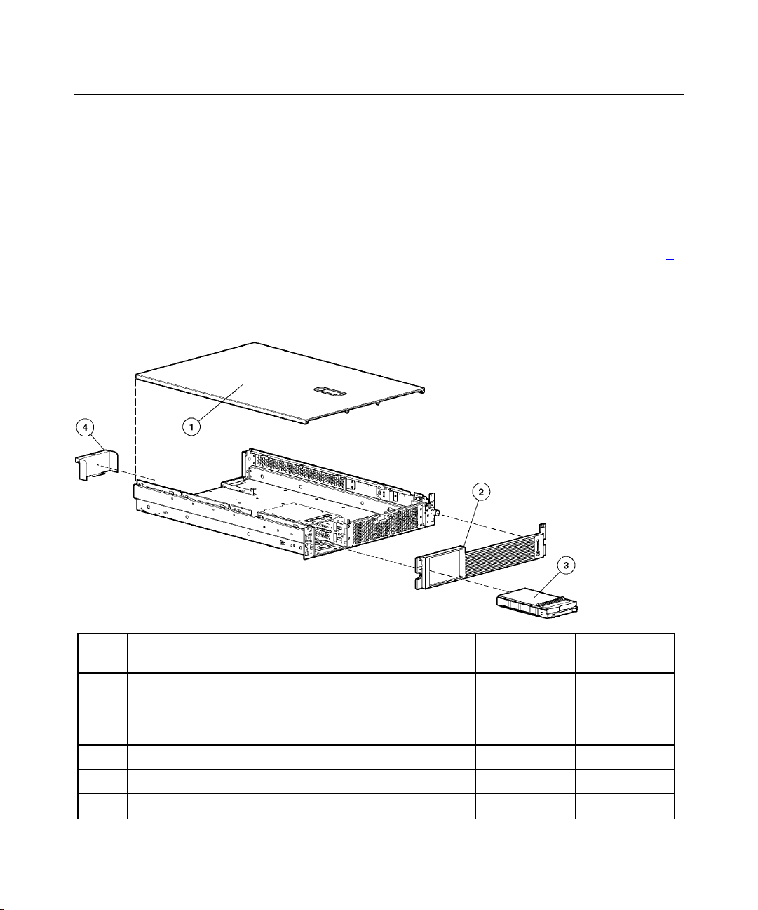
Mechanical Components
Item Description Assembly
Part Number
1 Access panel 302866-001 310794-001
2 Front bezel 302889-001 310797-001
3 Hard drive blank — 122759-001
4 Power supply blank 302886-001 310793-001
5 Torx T-15 tool* 107473-001 199630-001
* Not shown
Spare Part
Number
Page 8
8 HP ProLiant DL560 Server Maintenance and Service Guide
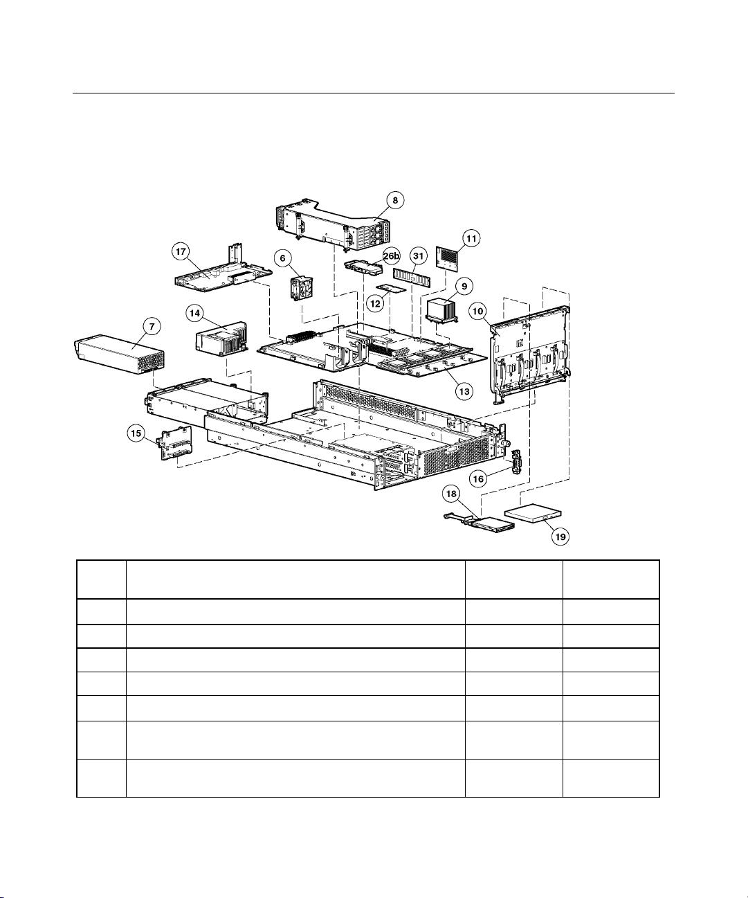
System Components
Item Description Assembly
Part Number
System Components
6 Hot-plug fan, 60 mm 289596-001 310795-001
7 Hot-plug power supply, 550 W 280126-001 300892-001
8 PCI riser cage 313004-001 295012-001
9 Processor assembly
a) Intel Pentium processor, Xeon MP, 2.0-GHz/1-MB L3
— 327839-001
cache
b) Intel Pentium processor, Xeon MP, 2.5-GHz/1-MB L3
— 327840-001
cache
Spare Part
Number
Page 9
Illustrated Parts Catalog 9
Item Description Assembly
Part Number
10 Removable media tray 313005-001 310796-001
11 PPM (Processor Power Module), 12 V, 81 A 292718-001 289564-001
12 Smart Array 5i Plus memory module 011665-001 260741-001
13 System board, with two-bay fan bracket and system
14 Power converter module 268189-001 292223-001
15 SCSI backplane, 2 bay 011548-001 295011-001
16 Power button/LED board with cable 011563-001 295015-001
17 Peripheral board 011560-001 295014-001
c) Intel Pentium processor, Xeon MP, 2.8-GHz/2-MB L3
cache
d) Intel Pentium processor, Xeon MP, 2.2 GHz/2-MB L3* — 352311-001
e) Intel Pentium processor, Xeon MP, 2.7 GHz/2-MB L3* — 352312-001
f) Intel Pentium processor, Xeon MP, 3.0 GHz/4-MB L3 — 352313-001
Boards
battery
Media Devices
— 327841-001
011557-001 295013-001
Spare Part
Number
18 Diskette drive, slimline, 1.44 MB 279983-001 228507-001
19 CD-ROM drive, removable slimline, IDE, 24X 222837-001 228508-001
20 DVD-ROM drive, removable slimline, 8X * 294766-9D1 337273-001
21 SCSI cable kit * 166298-440 320177-001
22 Smart Array 5i Plus Battery-Backed Write Cache Enabler
23 Rack mounting hardware kit * 300605-001 289570-001
24 Rack mounting hardware kit, round-hole* — 289572-001
Cables
cable kit*
Rack Mounting Hardware
Miscellaneous
— 283033-001
Page 10
10 HP ProLiant DL560 Server Maintenance and Service Guide
Item Description Assembly
Part Number
25 Hardware kit *
a) Screws, T-15, flathead
b) Expansion slot cover
c) Screws, 6-32
26 Plastics kit
a) PCI slot release lever *
b) Battery Backed-Write Cache Enabler bracket
c) Blank, tape drive *
27 AC power cord, IEC-IEC 10 ft. * 142263-003 142258-003
28 Battery, 3.3 V, lithium * 334149-001 153099-001
29 Country kit * — 320115-001
30 Return kit, pack box, and cushions * — 320116-001
31 DIMM, 256 MB, registered DDR SDRAM 300678-B21 300699-001
32 DIMM, 512 MB, registered DDR SDRAM * 300679-B21 300700-001
33 DIMM, 1 GB, registered DDR SDRAM * 300680-B21 300701-001
Memory
—
228213-001
228072-001
192308-009
—
228194-001
302925-001
218512-001
Spare Part
Number
228527-001
—
—
—
314688-001
—
—
—
34 DIMM, 2 GB, registered DDR SDRAM * 300682-B21 300702-001
35 Round-hole rack rail mounting kit * 293052-B21 289572-001
36 Battery-Backed Write Cache Enabler * 011665-001 260740-001
37 Hard Disk Drives
Options
a) 18.2-GB SCSI hard drive, U320, hot-plug, 15K* — 289240-001
b) 36.4-GB SCSI Hard drive, U320, hot-plug, 10K* — 289041-001
c) 36.4-GB SCSI Hard drive, U320, hot-plug, 15K* — 289241-001
d) 72.8-GB SCSI hard drive, U320, hot-plug, 10K* — 289042-001
e) 72.8-GB SCSI hard drive, U320, hot-plug, 15K* — 289243-001
f) 146.8-GB SCSI hard drive, U320, hot-plug, 10K* — 289044-001
Page 11
Illustrated Parts Catalog 11
Item Description Assembly
Part Number
* Not shown
Spare Part
Number
Page 12

Page 13

13
Removal and Replacement Procedures
In This Section
Safety Considerations...................................................................................................................14
Preparation Procedures.................................................................................................................15
Hot-Plug SCSI Hard Drive...........................................................................................................19
Hard Drive Blank .........................................................................................................................20
CD-ROM Drive............................................................................................................................20
CD-ROM Drive Blank..................................................................................................................21
Universal Hot-Plug Tape Drive....................................................................................................23
Tape Drive Blank .........................................................................................................................23
Hot-Plug Power Supply................................................................................................................24
Power Supply Blank.....................................................................................................................26
Hot-Plug Fan ................................................................................................................................27
Front Bezel ...................................................................................................................................28
Front Fan Module.........................................................................................................................29
Battery-Backed Write Cache Enabler Bracket .............................................................................31
Battery-Backed Write Cache Enabler...........................................................................................32
PCI Riser Cage .............................................................................................................................32
Expansion Board ..........................................................................................................................33
Expansion Slot Cover...................................................................................................................35
PCI Slot Release Lever.................................................................................................................35
Power Module ..............................................................................................................................37
DC Converter Module ..................................................................................................................39
Power Button/LED Board ............................................................................................................40
DIMMs .........................................................................................................................................43
Processor.......................................................................................................................................44
PPM ..............................................................................................................................................46
Smart Array 5i Plus Memory Module ..........................................................................................47
Battery ..........................................................................................................................................48
SCSI Cable ...................................................................................................................................49
SCSI Backplane............................................................................................................................50
Removable Media Tray ................................................................................................................51
Peripheral Board...........................................................................................................................53
System Board................................................................................................................................54
Rear Fan Bracket ..........................................................................................................................57
Re-Entering the Server Serial Number.........................................................................................58
Page 14

14 HP ProLiant DL560 Server Maintenance and Service Guide
You need the following items for some procedures:
• • Torx T-15 screwdriver (provided with the server)
Diagnostics Utility
Safety Considerations
Before performing service procedures, review all the safety information.
Preventing Electrostatic Discharge
To prevent damaging the system, be aware of the precautions you need to follow
when setting up the system or handling parts. A discharge of static electricity
from a finger or other conductor may damage system boards or other staticsensitive devices. This type of damage may reduce the life expectancy of the
device.
To prevent electrostatic damage:
•
Avoid hand contact by transporting and storing products in static-safe
containers.
•
Keep electrostatic-sensitive parts in their containers until they arrive at staticfree workstations.
•
Place parts on a grounded surface before removing them from their
containers.
•
Avoid touching pins, leads, or circuitry.
•
Always be properly grounded when touching a static-sensitive component or
assembly.
Server Warnings and Cautions
Before installing a server, be sure that you understand the following warnings
and cautions.
Page 15
Removal and Replacement Procedures 15
WARNING: To reduce the risk of electric shock or damage
to the equipment:
Do not disable the power cord grounding plug. The grounding
•
plug is an important safety feature.
•
Plug the power cord into a grounded (earthed) electric outlet
that is easily accessible at all times.
•
Unplug the power cord from the power supply to disconnect
power to the equipment.
•
Do not route the power cord where it can be walked on or
pinched by items placed against it. Pay particular attention to
the plug, electric outlet, and the point where the cord extends
from the server.
WARNING: To reduce the risk of personal injury from hot
surfaces, allow the drives and the internal system components to
cool before touching them.
CAUTION: Do not operate the server for long periods without
the access panel. Operating the server without the access panel results
in improper airflow and improper cooling that can lead to thermal
damage.
Preparation Procedures
To access some components and perform certain service procedures, you must
perform one or more of the following procedures:
• Extend the server from the rack ("Extending the Server from the Rack" on
page 17
If you are performing service procedures in a Compaq branded rack, telco
rack, or third-party rack cabinet, you can use the locking feature of the rack
rails to support the server and gain access to internal components.
For more information about telco rack solutions, refer to the
RackSolutions.com website (http://www.racksolutions.com/hp
).
).
Page 16
16 HP ProLiant DL560 Server Maintenance and Service Guide
• Power down the server ("Powering Down the Server" on page 16).
If you must remove a server from a rack or a non-hot-plug component from a
server, power down the server.
• Remove the server from the rack ("Removing the Server from the Rack" on
page 18
).
If the rack environment, cabling configuration, or the server location in the
rack creates awkward conditions, remove the server from the rack.
Powering Down the Server
WARNING: To reduce the risk of personal injury, electric
shock, or damage to the equipment, remove the power cord to
remove power from the server. The front panel Power On/Standby
button does not completely shut off system power. Portions of the
power supply and some internal circuitry remain active until AC
power is removed.
IMPORTANT: If installing a hot-plug device, it is not necessary to
power down the server.
1. Back up the server data.
2. Shut down the operating system as directed by the operating system
documentation.
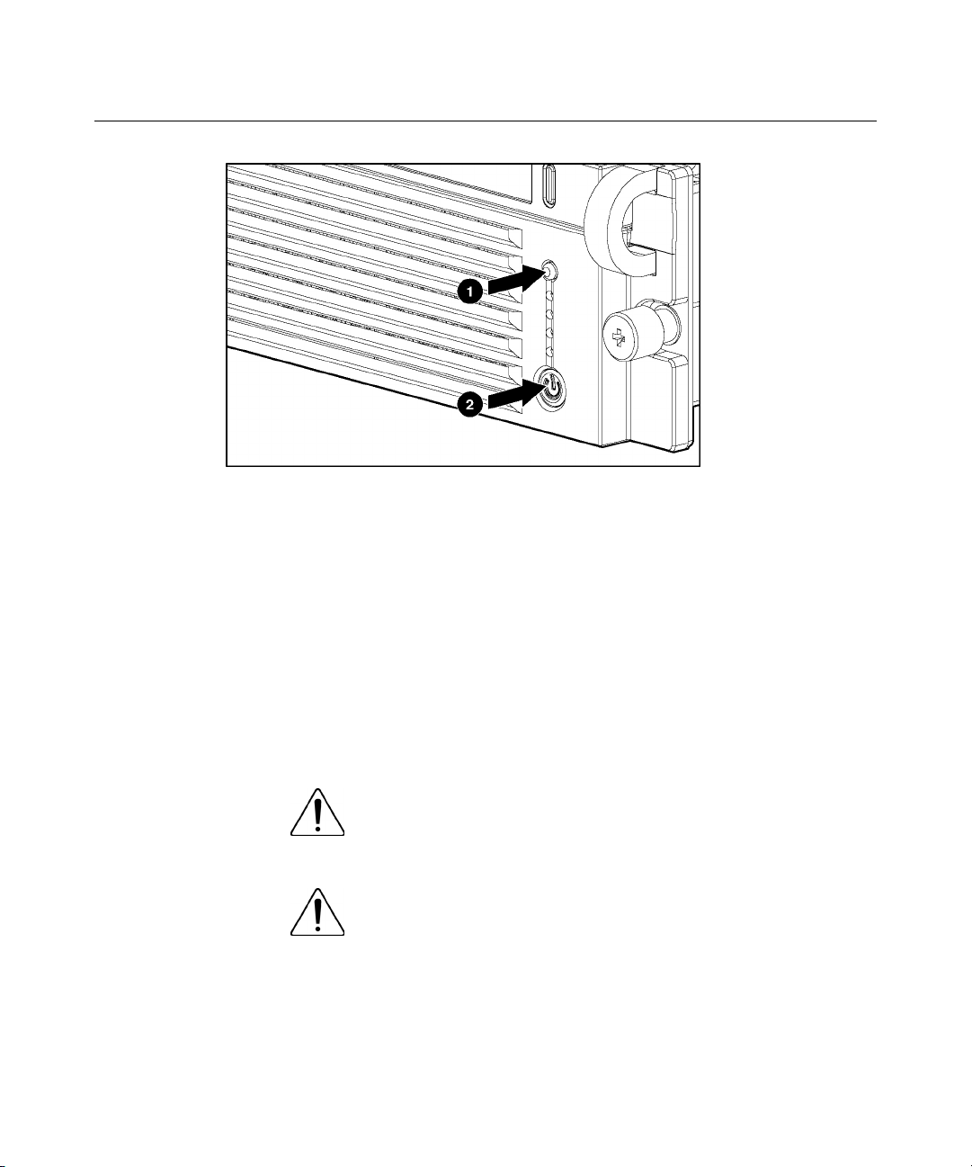
3. If the server is installed in a rack, press the UID LED/button on the front
panel (1). Blue LEDs illuminate on the front and rear panels of the server.
4. Press the Power On/Standby button to place the server in standby mode (2).
When the server activates standby power mode, the system power LED
changes to amber.
Page 17
Removal and Replacement Procedures 17
5. If the server is installed in a rack, locate the server by identifying the
illuminated rear UID LED button.
6. Disconnect the power cords.
The system is now without power.
Extending the Server from the Rack
1. Loosen the thumbscrews that secure the server faceplate to the front of the
rack.
2. Grasping the handles on the front bezel, extend the server on the rack rails
until the server rail-release latches engage.
WARNING: To reduce the risk of personal injury or
equipment damage, be sure that the rack is adequately stabilized
before extending a component from the rack.
WARNING: To reduce the risk of personal injury, be
careful when pressing the server rail-release latches and sliding
the server into the rack. The sliding rails could pinch your fingers.
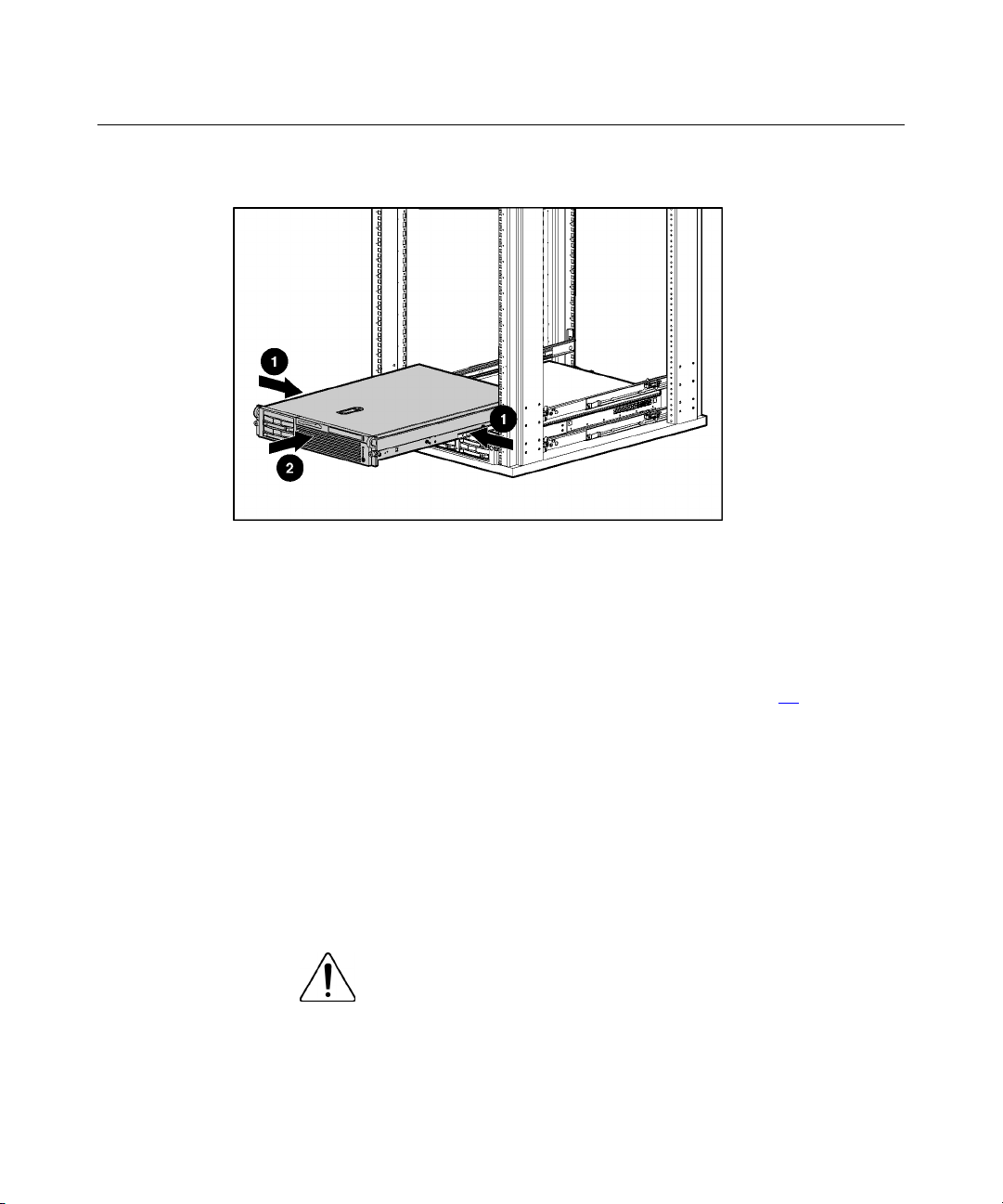
3. After performing the installation or maintenance procedure, slide the server
back into the rack:
Page 18
18 HP ProLiant DL560 Server Maintenance and Service Guide
a. Press the server rail-release latches and slide the server fully into rack.
b. Secure the server by tightening the thumbscrews.
Removing the Server from the Rack
To remove the server from a Compaq branded, telco, or third-party rack:
1. Power down the server ("Powering Down the Server" on page 16
2. Loosen the front panel thumbscrews that secure the server faceplate to the
front of the rack.
3. Disconnect the cabling and remove the server from the rack. Reverse the
server installation steps in the documentation that ships with the rackmounting option.
4. Place the server on a sturdy, level surface.
Removing the Access Panel
WARNING: To reduce the risk of personal injury from hot
surfaces, allow the drives and the internal system components to
cool before touching them.
).
Page 19
Removal and Replacement Procedures 19
CAUTION: Do not operate the server for long periods without
the access panel. Operating the server without the access panel results
in improper airflow and improper cooling that can lead to thermal
damage.
1. Power down the server if performing a non-hot-plug installation or
maintenance procedure ("Powering Down the Server" on page 16
).
2. Extend the server from the rack, if applicable ("Extending the Server from
the Rack" on page 17
3. Lift up on the hood latch handle and remove the access panel.
).
Hot-Plug SCSI Hard Drive
To remove the component:
CAUTION: To prevent improper cooling and thermal damage,
do not operate the server unless all bays are populated with either a
component or a blank.
1. Determine the status of the hard drive from the hot-plug hard drive LEDs
("Hot-Plug SCSI Hard Drive LEDs" on page 89
).
2. Back up all server data on the hard drive.
3. Remove the hard drive.
Page 20
20 HP ProLiant DL560 Server Maintenance and Service Guide
To replace the component, reverse the removal procedure.
Hard Drive Blank
To remove the component:
CAUTION: To prevent improper cooling and thermal damage,
do not operate the server unless all bays are populated with either a
component or a blank.
To replace the blank, slide the blank into the bay until it locks into place.
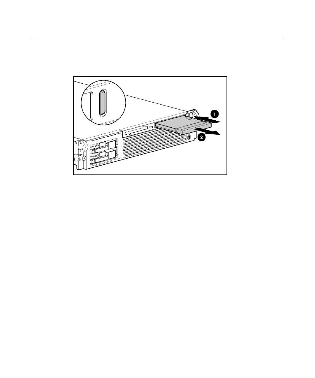
CD-ROM Drive
To remove the component:
1. Power down the server ("Powering Down the Server" on page 16).
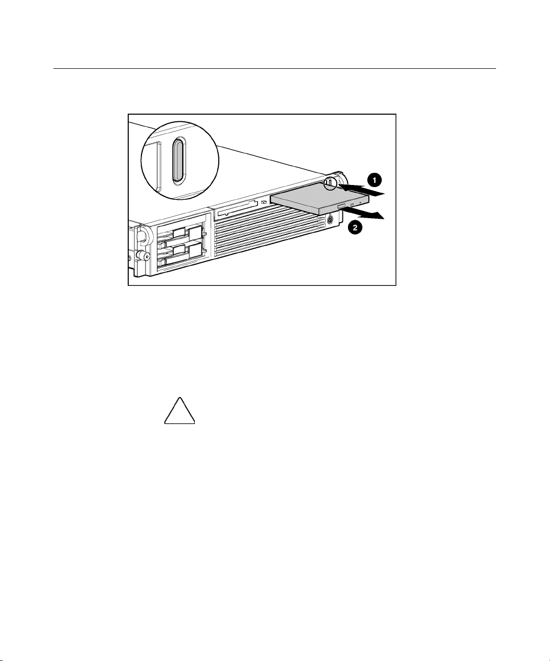
IMPORTANT: The ejector button is recessed to prevent accidental
ejection; it may be helpful to use the Torx T-15 tool on the back of the
server or similar shaped object to access the button.
Page 21
Removal and Replacement Procedures 21
2. Remove the CD-ROM drive.
To replace the CD-ROM drive, slide the drive into the bay until the drive is fully
seated.
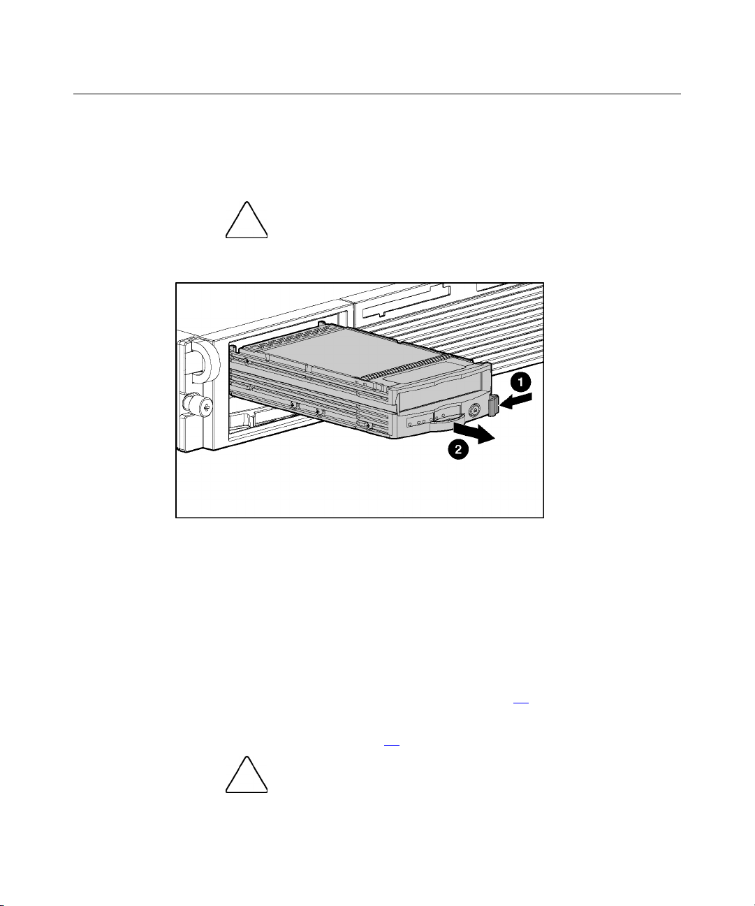
CD-ROM Drive Blank
To remove the component:
CAUTION: To prevent improper cooling and thermal damage,
do not operate the server unless all bays are populated with either a
component or a blank.
Page 22
22 HP ProLiant DL560 Server Maintenance and Service Guide
IMPORTANT: The ejector button is recessed to prevent accidental
ejection; it may be helpful to use the Torx T-15 tool on the back of the
server or similar shaped object to access the button.
To replace the blank, slide the blank into the bay until it locks into place.
Page 23
Removal and Replacement Procedures 23
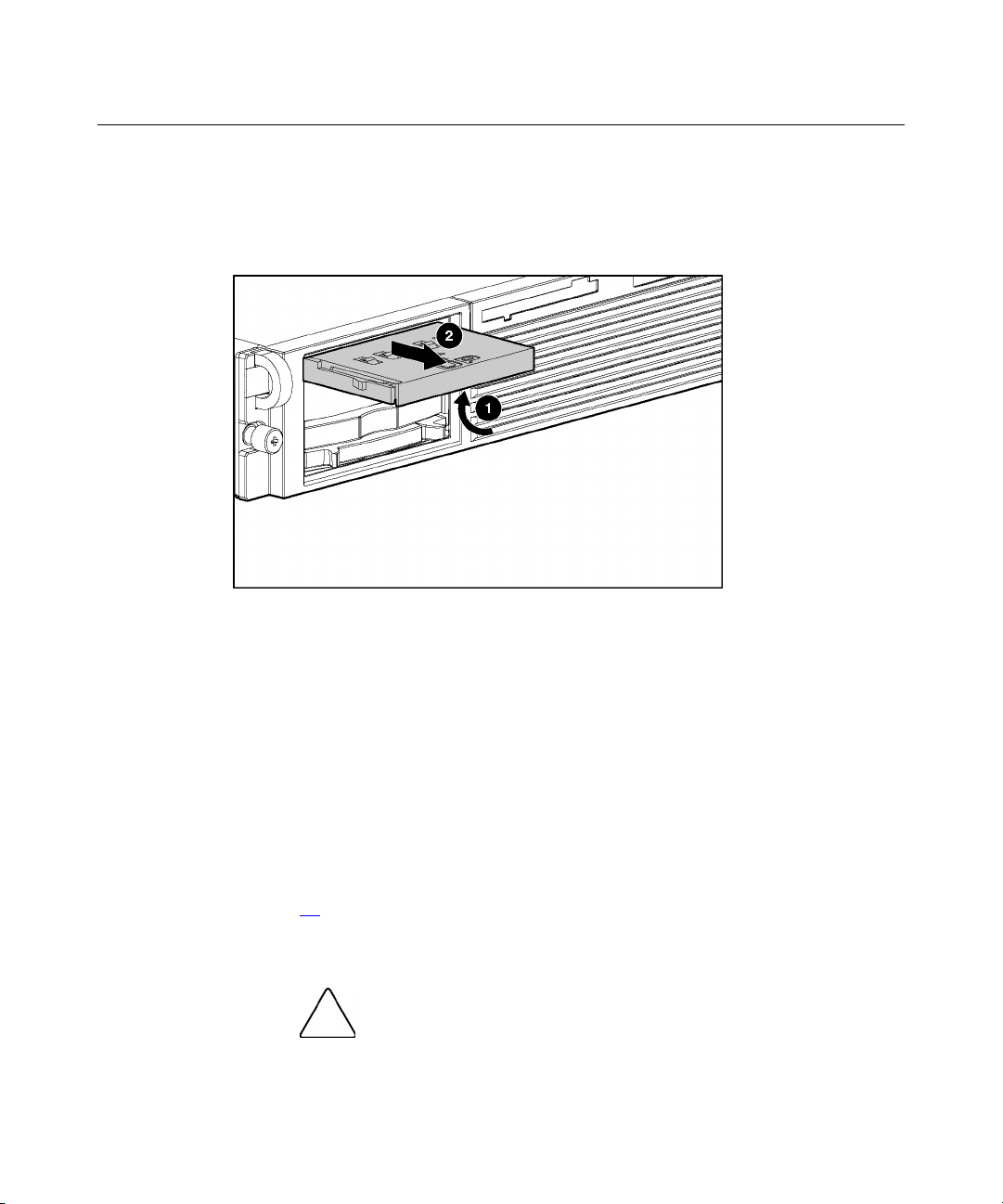
Universal Hot-Plug Tape Drive
To remove the component:
CAUTION: To prevent improper cooling and thermal damage,
do not operate the server unless all bays are populated with either a
component or a blank.
To replace the Universal Hot-Plug tape drive, slide the drive into the bay until it
locks into place.
Tape Drive Blank
To remove the component:
1. Remove the hot-plug SCSI hard drive, if one is installed, below the tape
drive blank ("Hot-Plug SCSI Hard Drive" on page 19
2. Remove the hard drive blank, if one is installed, below the tape drive blank
("Hard Drive Blank" on page 20
do not operate the server unless all bays are populated with either a
component or a blank.
).
).
CAUTION: To prevent improper cooling and thermal damage,
Page 24
24 HP ProLiant DL560 Server Maintenance and Service Guide
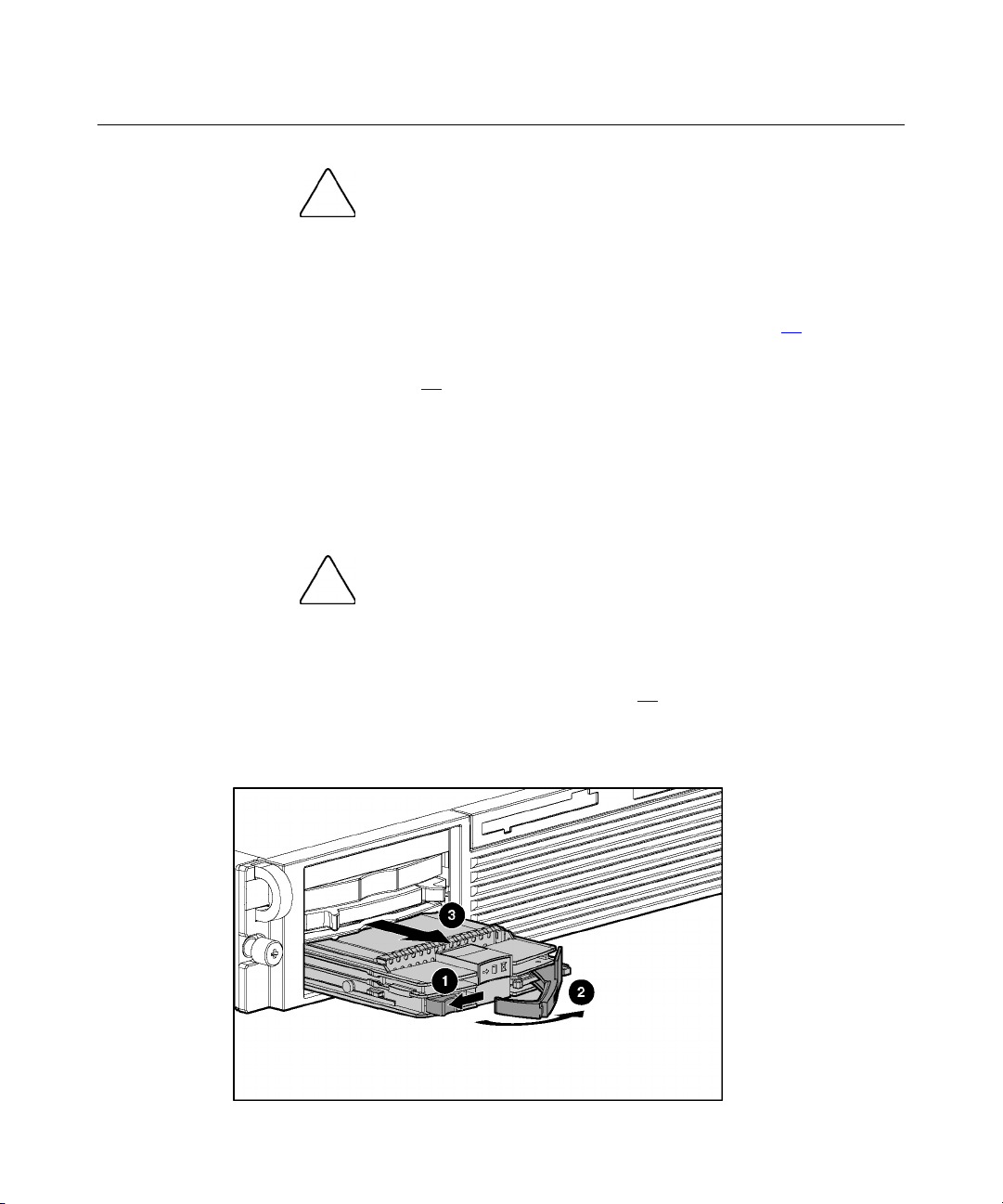
3. Remove the tape drive blank.
a. Reach underneath and squeeze the middle of the tape drive blank (1).
b. Pull the blank out of the bay (2).
4. To replace the blank, slide the blank into the bay until it locks into place.
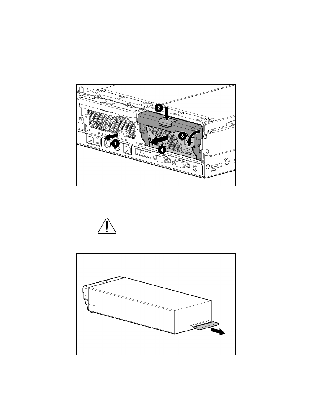
Hot-Plug Power Supply
To remove the component:
1. Unlock the hinge on the cable management arm and swing the arm away
from the power supply area.
2. Determine how many hot-plug power supplies are installed:
− If only one hot-plug power supply is installed, power down and remove
the power cord from the server ("Powering Down the Server" on page
).
16
− If more than one hot-plug power supply is installed, continue with the
next step.
CAUTION: To prevent improper cooling and thermal damage,
do not operate the server unless all bays are populated with either a
component or a blank.
Page 25
Removal and Replacement Procedures 25
3. Remove the shipping screw and then the hot-plug power supply.
IMPORTANT: The power supply shipping screw is not required for
server operation. It is only required for shipping.
To replace a hot-plug power supply:
1. Remove the protective cover from the connector pins on the power supply.
WARNING: To reduce the risk of electric shock or damage
to the equipment, do not connect the power cord to the power
supply until the power supply is installed.
Page 26
26 HP ProLiant DL560 Server Maintenance and Service Guide
2. Slide the power supply into the power supply bay.
3. Connect the power cord to the power supply.
4. Route the power cord through the cable management arm or power cord
anchor.
NOTE: If using the power cord anchor, be sure to leave enough slack
in the power cord so that the redundant power supply can be removed
without disconnecting the power cord from the primary power supply.
5. Lock the cable management arm into the operating position.
Power Supply Blank
To remove the component:
1. Unlock the hinge on the cable management arm and swing the arm away
from the power supply area.
CAUTION: To prevent improper cooling and thermal damage,
do not operate the server unless all bays are populated with either a
component or a blank.
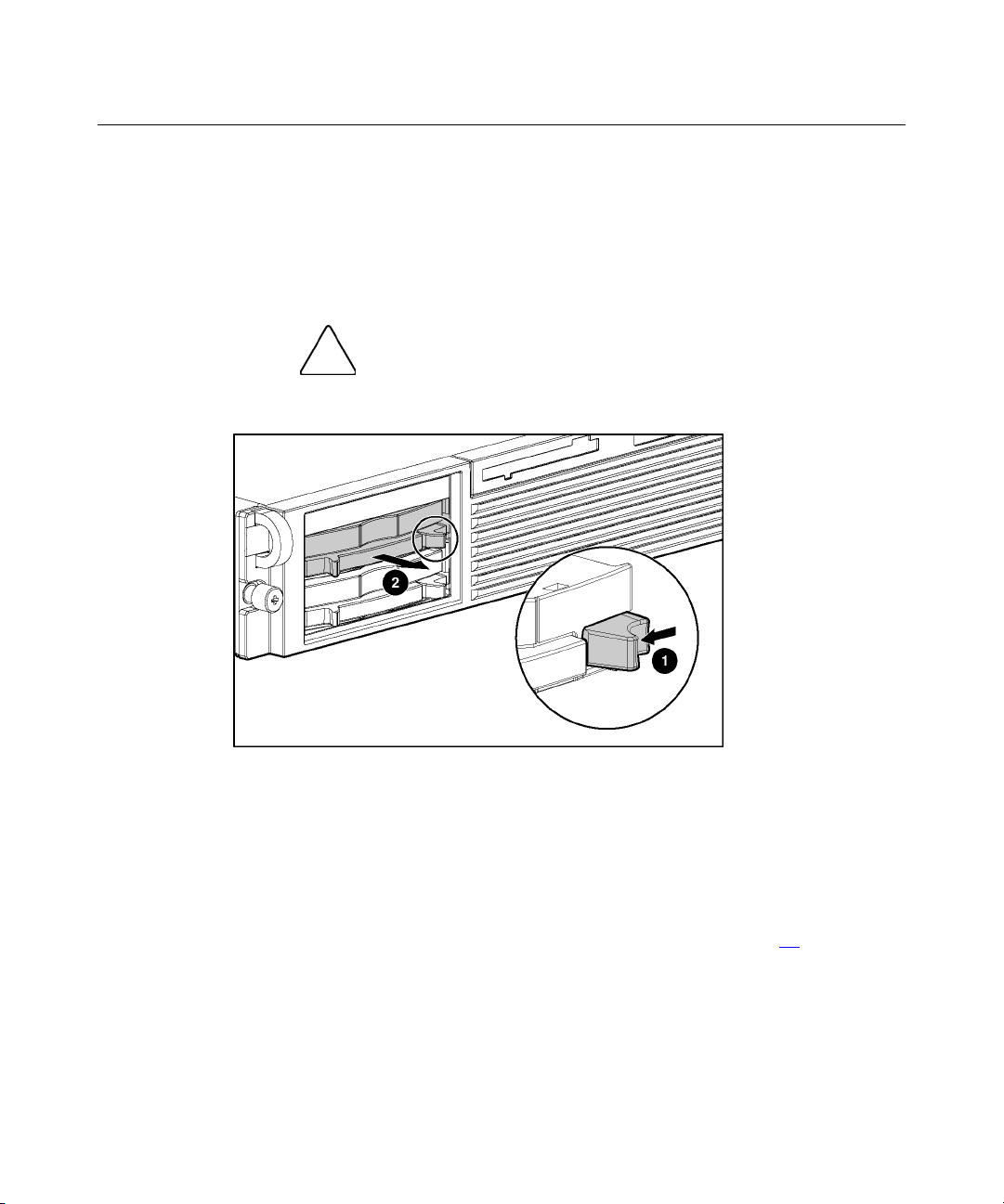
2. Remove the power supply blank.
To replace a power supply blank:
Page 27
Removal and Replacement Procedures 27
1. Slide the power supply blank into the bay until it locks into place.
2. Swing the cable management arm into place and lock it.
Hot-Plug Fan
To remove the component:
1. Extend or remove the server from the rack ("Extending the Server from the
Rack" on page 17
, "Removing the Server from the Rack" on page 18).
2. Remove the access panel ("Removing the Access Panel" on page 18
3. Determine whether the fan is operating with redundancy:
− If the fan zone is not operating with redundancy, power down the server
("Powering Down the Server" on page 16
).
− If the fan zone is operating with redundancy, continue with the next step.
For information on fan redundancy, refer to "Redundant Hot-Plug Fan
Option (on page 93
)."
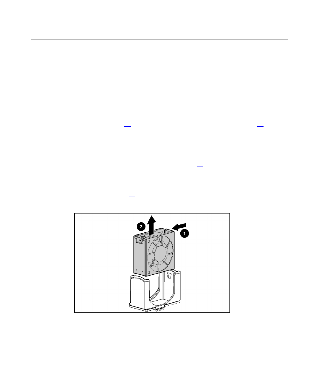
4. Remove the fan.
).
Page 28
28 HP ProLiant DL560 Server Maintenance and Service Guide
CAUTION: Do not operate the server for long periods without
the access panel. Operating the server without the access panel results
in improper airflow and improper cooling that can lead to thermal
damage.
IMPORTANT: For optimum cooling, install fans in all primary fan
locations. For more information, refer to the previous fan locations table.
To replace the component, reverse the removal procedure.
Front Bezel
To remove the component:
1. Power down the server ("Powering Down the Server" on page 16
).
2. Extend or remove the server from the rack ("Extending the Server from the
Rack" on page 17
3. Remove all hard drives ("Hot-Plug SCSI Hard Drive" on page 19
, "Removing the Server from the Rack" on page 18).
).
4. Remove the six screws (three on each side) from the front bezel.
Page 29
Removal and Replacement Procedures 29
5. Remove the front bezel.
To replace the component, reverse the removal procedure.
Front Fan Module
To remove the component:
1. Power down the server ("Powering Down the Server" on page 16
).
2. Extend or remove the server from the rack ("Extending the Server from the
Rack" on page 17
3. Remove the access panel ("Removing the Access Panel" on page 18
, "Removing the Server from the Rack" on page 18).
).
Page 30
30 HP ProLiant DL560 Server Maintenance and Service Guide
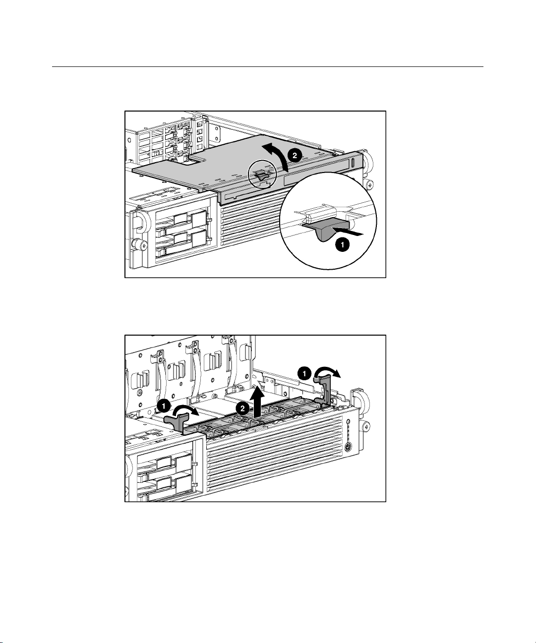
4. Lift the removable media tray.
5. Remove the fan module.
NOTE: Fans do not have to be removed to install or remove the fan
module.
To replace the front fan bracket, reverse the removal steps and press down on the
top of each fan to be sure it is seated properly.
Page 31

Removal and Replacement Procedures 31
Battery-Backed Write Cache Enabler Bracket
To remove the component:
1. Power down the server ("Powering Down the Server" on page 16
).
2. Extend or remove the server from the rack ("Extending the Server from the
Rack" on page 17
3. Remove the access panel ("Removing the Access Panel" on page 18
, "Removing the Server from the Rack" on page 18).
).
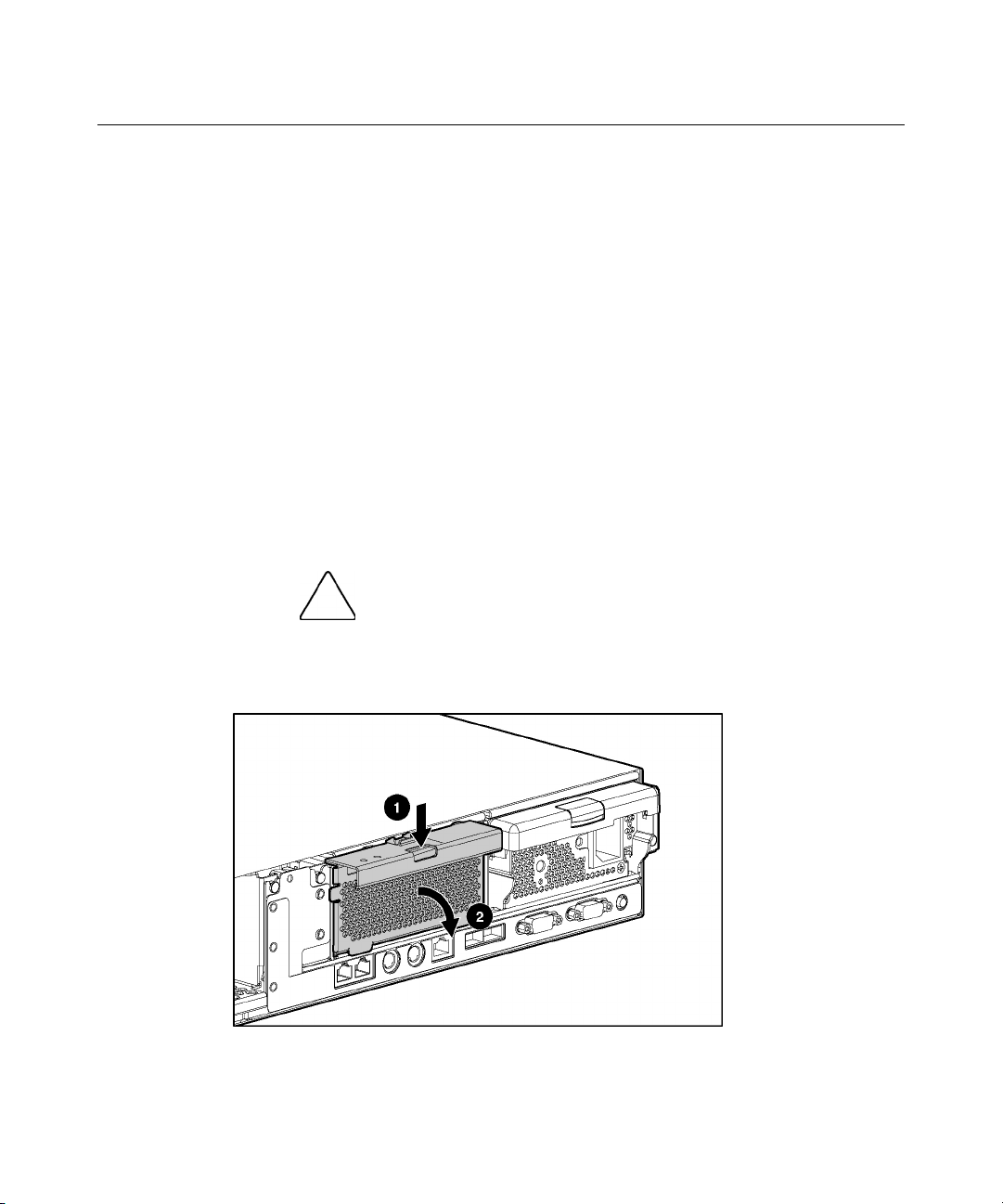
4. Remove the battery module bracket:
a. Turn the pins on the battery module bracket (1) and lift the battery
module bracket from the chassis (2).
b. If the battery module is installed, be sure the amber LED on the battery
module is not blinking. If the amber LED is blinking, the battery module
is backing up data. Wait until the LED stops blinking before continuing
to the next step.
c. If the battery module is installed, disconnect the cable from the Smart
Array 5i Plus memory module (3).
CAUTION: Disconnecting the battery module cable will cause
any unsaved data in the memory module to be lost.
5. To replace the component, reverse the removal procedure.
Page 32

32 HP ProLiant DL560 Server Maintenance and Service Guide
Battery-Backed Write Cache Enabler
To remove the component:
1. Power down the server ("Powering Down the Server" on page 16
).
2. Extend or remove the server from the rack ("Extending the Server from the
Rack" on page 17
3. Remove the access panel ("Removing the Access Panel" on page 18
, "Removing the Server from the Rack" on page 18).
).
4. Remove the Battery-Backed Write Cache Enabler bracket ("Battery-Backed
Write Cache Enabler Bracket" on page 31
).
5. Remove the battery module from the bracket.
To replace the component, reverse the removal procedure.
PCI Riser Cage
To remove the component:
boards, power down the server and remove all AC power cords before
removing or installing the PCI riser cage.
CAUTION: To prevent damage to the server or expansion
Page 33

Removal and Replacement Procedures 33
1. Power down the server ("Powering Down the Server" on page 16).
2. Extend the server from the rack, if applicable ("Extending the Server from
the Rack" on page 17
).
3. Remove the access panel ("Removing the Access Panel" on page 18
4. Disconnect any internal or external cables connected to any existing
expansion boards.
5. Remove the PCI riser cage.
To replace the component, reverse the removal procedure.
Expansion Board
).
To remove the component:
1. Extend or remove the server from the rack ("Extending the Server from the
Rack" on page 17
2. Remove the access panel ("Removing the Access Panel" on page 18
, "Removing the Server from the Rack" on page 18).
).
Page 34

34 HP ProLiant DL560 Server Maintenance and Service Guide
3. Unlock the PCI retaining clip.
CAUTION: To prevent improper cooling and thermal damage,
do not operate the server unless all PCI slots have either an expansion
slot cover or an expansion board installed.
4. Remove the expansion board.
To replace the component, reverse the removal procedure.
Page 35

Removal and Replacement Procedures 35
Expansion Slot Cover
To remove the component:
1. Power down the server ("Powering Down the Server" on page 16
).
2. Extend or remove the server from the rack ("Extending the Server from the
Rack" on page 17
3. Remove the access panel ("Removing the Access Panel" on page 18
4. Remove the PCI riser cage ("PCI Riser Cage" on page 32
CAUTION: To prevent damage to the server or expansion
boards, power down the server and remove all AC power cords before
removing or installing the PCI riser cage.
, "Removing the Server from the Rack" on page 18).
).
).
5. Remove the expansion slot cover.
PCI Slot Release Lever
To remove the component:
1. Power down the server ("Powering Down the Server" on page 16
2. Extend or remove the server from the rack ("Extending the Server from the
Rack" on page 17
, "Removing the Server from the Rack" on page 18).
).
Page 36

36 HP ProLiant DL560 Server Maintenance and Service Guide
3. Remove the access panel ("Removing the Access Panel" on page 18).
4. Remove the PCI riser cage ("PCI Riser Cage" on page 32
CAUTION: To prevent damage to the server or expansion
boards, power down the server and remove all AC power cords before
removing or installing the PCI riser cage.
).
5. Remove the expansion board from the slot, if installed ("Expansion Board"
on page 33
).
6. Remove the expansion slot cover from the slot, if installed ("Expansion Slot
Cover" on page 35
).
7. Open the PCI slot release lever.
Page 37

Removal and Replacement Procedures 37
8. Remove the PCI slot release lever.
To replace the component, reverse the removal procedure.
Power Module
To remove the component:
1. Power down the server ("Powering Down the Server" on page 16
).
2. Extend or remove the server from the rack ("Extending the Server from the
Rack" on page 17
3. Remove the access panel ("Removing the Access Panel" on page 18
, "Removing the Server from the Rack" on page 18).
).
Page 38

38 HP ProLiant DL560 Server Maintenance and Service Guide
4. Disconnect internal power cables.
5. Remove power module.
To replace the component, reverse the removal procedure.
Page 39

Removal and Replacement Procedures 39
DC Converter Module
To remove the component:
NOTE: You do not have to remove the DC converter module to remove
the power module.
1. Power down the server ("Powering Down the Server" on page 16).
2. Extend or remove the server from the rack ("Extending the Server from the
Rack" on page 17
, "Removing the Server from the Rack" on page 18).
3. Remove the access panel ("Removing the Access Panel" on page 18
4. Disconnect internal power cables.
5. Partially remove any installed power supplies ("Hot-Plug Power Supply" on
page 24
). You do not need to completely remove the power supplies.
).
Page 40

40 HP ProLiant DL560 Server Maintenance and Service Guide
6. Remove the DC converter module.
Power Button/LED Board
To remove the component:
1. Power down the server ("Powering Down the Server" on page 16
2. Extend or remove the server from the rack ("Extending the Server from the
Rack" on page 17
3. Remove the access panel ("Removing the Access Panel" on page 18
, "Removing the Server from the Rack" on page 18).
).
).
Page 41

Removal and Replacement Procedures 41
4. Lift the removable media tray.
5. Remove the front fan module.
Page 42

42 HP ProLiant DL560 Server Maintenance and Service Guide
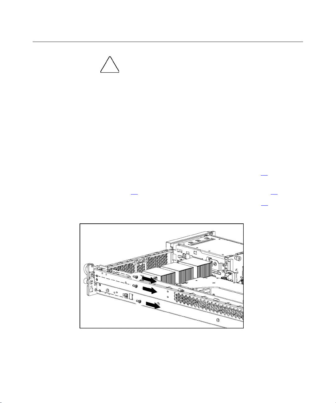
6. Remove the screws from the front bezel to expose the power button/LED
board.
7. Remove the power button/LED board.
To replace the component, reverse the removal procedure.
Page 43

Removal and Replacement Procedures 43
DIMMs
To remove the component:
1. Power down the server ("Powering Down the Server" on page 16
).
2. Extend or remove the server from the rack ("Extending the Server from the
Rack" on page 17
3. Remove the access panel ("Removing the Access Panel" on page 18
NOTE: The server ships with at least two DIMMs installed in DIMM
slots 1A and 2A.
, "Removing the Server from the Rack" on page 18).
).
4. Remove the DIMM.
CAUTION: Be sure to install DIMMs in the proper
configuration. Refer to the Documentation CD.
CAUTION: Use only Compaq branded or HP DIMMs. DIMMs
from other sources may adversely affect data integrity.
IMPORTANT: DIMMs do not seat fully if turned the wrong way.
To replace a DIMM, align the DIMM with the slot and insert the DIMM firmly.
When fully seated, the DIMM slot latches lock into place.
Page 44

44 HP ProLiant DL560 Server Maintenance and Service Guide
Processor
To remove the component:
1. Power down the server ("Powering Down the Server" on page 16
).
2. Extend or remove the server from the rack ("Extending the Server from the
Rack" on page 17
3. Remove the access panel ("Removing the Access Panel" on page 18
, "Removing the Server from the Rack" on page 18).
).
4. Lift the removable media tray.
CAUTION: To prevent thermal instability and damage to the
server, do not separate the processor from the heatsink. The processor,
heatsink, and retaining clip make up a single assembly.
5. Remove the processor and heatsink assembly.
Page 45

Removal and Replacement Procedures 45
CAUTION: Failure to open the processor locking lever
completely prevents the processor from seating during installation,
leading to hardware damage.
CAUTION: To prevent possible server malfunction and
damage to the equipment, do not mix processors of different types.
CAUTION: To prevent possible server malfunction or damage
to the equipment, be sure to align the processor pins with the
corresponding holes in the socket.
IMPORTANT: Processor socket 1 and PPM slot 1 must be populated
at all times or the server will not function properly.
IMPORTANT: PPM slots must be populated when processors are
installed. If PPM slots are not populated, the server does not boot or
halts during POST.
IMPORTANT: If you replace a failed processor or processors, clear the
status log in RBSU after powering up the server. For RBSU procedures,
refer to the Documentation CD.
To replace the component, reverse the removal procedure.
Page 46

46 HP ProLiant DL560 Server Maintenance and Service Guide
CAUTION: To prevent possible server malfunction or damage
to the equipment, be sure to completely close the processor locking
lever.
PPM
To remove the component:
1. Power down the server ("Powering Down the Server" on page 16
).
2. Extend or remove the server from the rack ("Extending the Server from the
Rack" on page 17
3. Remove the access panel ("Removing the Access Panel" on page 18
NOTE: The appearance of compatible PPMs may vary.
, "Removing the Server from the Rack" on page 18).
).
4. Remove the PPM.
IMPORTANT: PPM slots must be populated when processors are
installed. If PPM slots are not populated, the server does not boot or
halts during POST.
To replace the component, reverse the removal procedure.
Page 47

Removal and Replacement Procedures 47
Smart Array 5i Plus Memory Module
To remove the component:
1. Power down the server ("Powering Down the Server" on page 16
).
2. Extend or remove the server from the rack ("Extending the Server from the
Rack" on page 17
3. Remove the access panel ("Removing the Access Panel" on page 18
4. Remove the PCI riser cage ("PCI Riser Cage" on page 32
CAUTION: To prevent damage to the server or expansion
boards, power down the server and remove all AC power cords before
removing or installing the PCI riser cage.
CAUTION: Disconnecting the battery module cable will cause
any unsaved data in the memory module to be lost.
, "Removing the Server from the Rack" on page 18).
).
).
5. Disconnect and remove the Smart Array 5i Plus memory module cable.
6. Remove the Smart Array 5i Plus memory module.
To replace the component, reverse the removal procedure.
Page 48

48 HP ProLiant DL560 Server Maintenance and Service Guide
CAUTION: To prevent damage to the memory module during
installation, be sure the memory module is fully inserted before pressing
down.
Battery
If the server no longer automatically displays the correct date and time, you may
need to replace the battery that provides power to the real-time clock. Under
normal use, battery life is 5 to 10 years.
WARNING: The computer contains an internal lithium
manganese dioxide, a vanadium pentoxide, or an alkaline battery
pack. A risk of fire and burns exists if the battery pack is not
properly handled. To reduce the risk of personal injury:
Do not attempt to recharge the battery. •
•
Do not expose the battery to temperatures higher than
60°C (140°F).
•
Do not disassemble, crush, puncture, short external contacts,
or dispose of in fire or water.
•
Replace only with the spare designated for this product.
To remove the component:
1. Power down the server ("Powering Down the Server" on page 16
).
2. Extend or remove the server from the rack ("Extending the Server from the
Rack" on page 17
3. Remove the access panel ("Removing the Access Panel" on page 18
4. Remove the power module ("Power Module" on page 37
, "Removing the Server from the Rack" on page 18).
).
).
Page 49

Removal and Replacement Procedures 49
5. Remove the battery.
IMPORTANT: Replacing the system board battery resets the system
ROM to its default configuration. After replacing the battery, reconfigure
the system through RBSU.
To replace the component, reverse the removal procedure.
For more information about battery replacement or proper disposal, contact an
authorized reseller or authorized service provider.
SCSI Cable
To remove the component:
1. Power down the server ("Powering Down the Server" on page 16
2. Extend or remove the server from the rack ("Extending the Server from the
3. Remove the access panel ("Removing the Access Panel" on page 18
Rack" on page 17
).
, "Removing the Server from the Rack" on page 18).
).
Page 50

50 HP ProLiant DL560 Server Maintenance and Service Guide
4. Disconnect and remove the SCSI cable.
To replace the component, reverse the removal procedure.
SCSI Backplane
To remove the component:
1. Power down the server ("Powering Down the Server" on page 16
).
2. Extend or remove the server from the rack ("Extending the Server from the
Rack" on page 17
3. Remove the access panel ("Removing the Access Panel" on page 18
, "Removing the Server from the Rack" on page 18).
).
4. Remove all hot-plug SCSI hard drives ("Hot-Plug SCSI Hard Drive" on page
).
19
5. Remove the tape drive, if installed ("Universal Hot-Plug Tape Drive" on
page 23
).
Page 51

Removal and Replacement Procedures 51
6. Disconnect cables connected to the SCSI backplane.
7. Remove the SCSI backplane.
To replace the component, reverse the removal procedure.
Removable Media Tray
To remove the component:
1. Power down the server ("Powering Down the Server" on page 16).
Page 52

52 HP ProLiant DL560 Server Maintenance and Service Guide
2. Extend or remove the server from the rack ("Extending the Server from the
Rack" on page 17
, "Removing the Server from the Rack" on page 18).
3. Remove the access panel ("Removing the Access Panel" on page 18
4. Lift the removable media tray.
5. Disconnect cables from the system board.
).
Page 53

Removal and Replacement Procedures 53
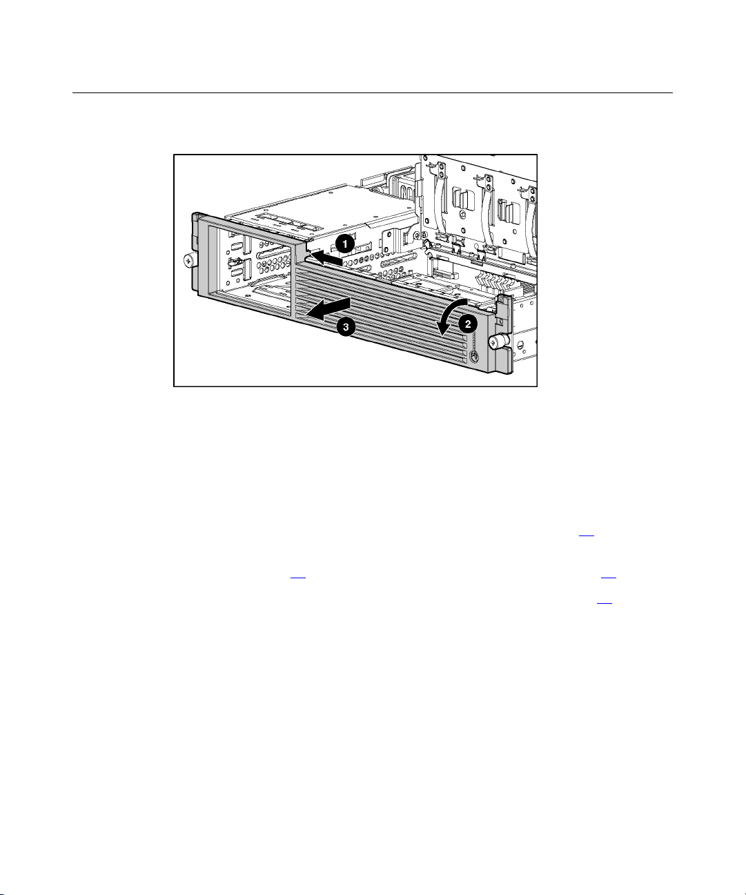
6. Remove the removable media tray.
Peripheral Board
To remove the component:
1. Power down the server ("Powering Down the Server" on page 16
2. Extend or remove the server from the rack ("Extending the Server from the
Rack" on page 17
3. Remove the access panel ("Removing the Access Panel" on page 18
4. Remove the power module ("Power Module" on page 37
5. Remove the PCI riser cage ("PCI Riser Cage" on page 32
).
, "Removing the Server from the Rack" on page 18).
).
).
).
Page 54

54 HP ProLiant DL560 Server Maintenance and Service Guide
6. Release the peripheral board from the system board.
7. Remove the peripheral board.
System Board
To remove the component:
1. Power down the server ("Powering Down the Server" on page 16
).
Page 55

Removal and Replacement Procedures 55
2. Extend or remove the server from the rack ("Extending the Server from the
Rack" on page 17
, "Removing the Server from the Rack" on page 18).
3. Remove the access panel ("Removing the Access Panel" on page 18
4. Remove the PCI riser cage ("PCI Riser Cage" on page 32
CAUTION: To prevent damage to the server or expansion
boards, power down the server and remove all AC power cords before
removing or installing the PCI riser cage.
).
).
5. Remove the power module ("Power Module" on page 37).
6. Remove the peripheral board ("Peripheral Board" on page 53
7. Remove the removable media tray ("Removable Media Tray" on page 51
8. Remove the front fan bracket ("Front Fan Module" on page 29
IMPORTANT: For this procedure, you do not need to remove the hotplug fans from the front fan bracket. When reinstalling the front fan
bracket, press the top of each fan to be sure it seats securely.
).
).
).
9. Remove the hot-plug fans from the rear fan bracket ("Hot-Plug Fan" on page
27
).
10. Remove the processors ("Processor" on page 44
NOTE: When removing the system board, you may leave the DIMMs,
the PPMs, the Smart Array 5i memory module, and the system battery
on the system board, unless you are replacing them as failed items.
).
11. Disconnect all cables connected to the system board.
Page 56

56 HP ProLiant DL560 Server Maintenance and Service Guide
12. Remove the system board thumbscrew.
13. Identify the alignment keys and keyhole locations.
Page 57

Removal and Replacement Procedures 57
14. Remove the system board.
NOTE: The system board spare kit does not includes DIMMs,
processors, PPMs, or the Smart Array 5i memory module.
To replace the component, reverse the removal procedure.
IMPORTANT: If replacing the system board or clearing NVRAM, you
must re-enter the server serial number through RBSU ("Re-Entering the
Server Serial Number" on page 58
).
Rear Fan Bracket
To remove the component:
1. Remove the system board ("System Board" on page 54
NOTE: When removing the system board, you may leave the DIMMs,
the PPMs, the Smart Array 5i memory module, and the system battery
on the system board, unless you are replacing them as failed items.
).
Page 58

58 HP ProLiant DL560 Server Maintenance and Service Guide
2. Remove the rear fan bracket.
To replace the component, reverse the removal procedure.
Re-Entering the Server Serial Number
After you replace the system board or clear NVRAM, you must re-enter the
server serial number.
1. During the server startup sequence, press the F9 key to access RBSU.
2. Select the System Options menu.
3. Select Serial Number. The following warning is displayed:
WARNING! WARNING! WARNING! The serial number is loaded
into the system during the manufacturing process and
should NOT be modified. This option should only be used
by qualified service personnel. This value should always
match the serial number sticker located on the chassis.
4. Press the Enter key to clear the warning.
5. Enter the serial number and press the Enter key.
6. Press the Escape key to close the menu.
7. Press the Escape key to exit RBSU.
Page 59

Removal and Replacement Procedures 59
8. Press the F10 key to confirm exiting RBSU. The server will automatically
reboot.
Page 60

Page 61

61
Diagnostic Tools
In This Section
Automatic Server Recovery..........................................................................................................61
Insight Manager 7.........................................................................................................................62
Integrated Management Log.........................................................................................................62
Integrated Lights-Out Technology ...............................................................................................63
iLO ROM-Based Setup Utility.....................................................................................................63
Option ROM Configuration for Arrays........................................................................................64
ProLiant Essentials Rapid Deployment Pack ...............................................................................65
ROM-Based Setup Utility ............................................................................................................65
ROMPaq Utility............................................................................................................................65
Smart Components for Remote ROM Flash.................................................................................66
SmartStart Software......................................................................................................................66
Survey Utility ...............................................................................................................................67
Automatic Server Recovery
ASR is a feature that causes the system to restart when a catastrophic operating
system error occurs, such as a blue screen, ABEND (abnormal end), or panic. A
system fail-safe timer, the ASR timer, starts when the System Management
driver, also known as the Health Driver, is loaded. When the operating system is
functioning properly, the system periodically resets the timer. However, when the
operating system fails, the timer expires and restarts the server.
ASR increases server availability by restarting the server within a specified time
after a system hang or shutdown. At the same time, the Insight Manager 7
console notifies you by sending a message to a designated pager number that
ASR has restarted the system. You can disable ASR from the Insight Manager 7
console or through RBSU.
Page 62

62 HP ProLiant DL560 Server Maintenance and Service Guide
Insight Manager 7
Insight Manager 7 is a Web-based application that allows system administrators
to accomplish normal administrative tasks from any remote location, using a
Web browser. Insight Manager 7 provides device management capabilities that
consolidate and integrate management data from HP and third-party devices.
IMPORTANT: You must install and use Insight Manager 7 to benefit
from the Pre-Failure Warranty for processors, hard drives, and memory
modules.
For additional information, refer to the Management CD in the HP ProLiant
Essentials Foundation Pack.
Integrated Management Log
The IML records hundreds of events and stores them in an easy-to-view form.
The IML timestamps each event with 1-minute granularity.
You can view recorded events in the IML in several ways, including the
following:
•
From within Insight Manager 7
•
From within Survey Utility
•
From within operating system-specific IML viewers
− For NetWare: IML Viewer
− For Windows®: Event Viewer or IML Viewer
− For Linux: IML Viewer Application
•
From within HP Insight Diagnostics
For more information, refer to the Management CD in the HP ProLiant
Essentials Foundation Pack.
Page 63

Diagnostic Tools 63
Integrated Lights-Out Technology
Integrated Lights-Out is a standard component of selected ProLiant servers that
provides server health and remote server manageability. The iLO subsystem
includes an intelligent microprocessor, secure memory, and a dedicated network
interface. This design makes iLO independent of the host server and its operating
system. The iLO subsystem provides remote access to any authorized network
client, sends alerts, and provides other server management functions.
Using iLO, you can:
•
Remotely power up, power down, or reboot the host server.
•
Send alerts from iLO regardless of the state of the host server.
•
Access advanced troubleshooting features through the iLO interface.
•
Diagnose iLO using Insight Manager 7 through a Web browser and SNMP
alerting.
For more information about iLO features, refer to the Integrated Lights-Out User
Guide on the Documentation CD or on the HP website
(http://www.hp.com/servers/lights-out
).
iLO ROM-Based Setup Utility
HP recommends using iLO RBSU to configure and set up iLO. iLO RBSU is
designed to assist you with setting up iLO on a network; it is not intended for
continued administration.
To run iLO RBSU:
1. Restart or power up the server.
2. Press the F8 key when prompted during POST. The iLO RBSU runs.
3. Enter a valid iLO user ID and password with the appropriate iLO privileges
(Administer User Accounts, Configure iLO Settings). Default account
information is located on the iLO Default Network Settings tag.
4. Make and save any necessary changes to the iLO configuration.
5. Exit iLO RBSU.
Page 64

64 HP ProLiant DL560 Server Maintenance and Service Guide
HP recommends using DNS/DHCP with iLO to simplify installation. If
DNS/DHCP cannot be used, use the following procedure to disable DNS/DHCP
and to configure the IP address and the subnet mask:
1. Restart or power up the server.
2. Press the F8 key when prompted during POST. The iLO RBSU runs.
3. Enter a valid iLO user ID and password with the appropriate iLO privileges
(Administer User Accounts, Configure iLO Settings). Default account
information is located on the iLO Default Network Settings tag.
4. Select Network, DNS/DHCP, press the Enter key, and then select DHCP
Enable. Press the spacebar to turn off DHCP. Be sure that DHCP Enable is
set to Off and save the changes.
5. Select Network, NIC and TCP/IP, press the Enter key, and type the
appropriate information in the IP Address, Subnet Mask and Gateway IP
Address fields.
6. Save the changes. The iLO system automatically resets to use the new setup
when you exit iLO RBSU.
Option ROM Configuration for Arrays
Before installing an operating system, you can use the ORCA utility to create the
first logical drive, assign RAID levels, and establish online spare configurations.
The utility provides support for the following functions:
•
Configuring one or more logical drives using physical drives on one or more
SCSI buses
•
Viewing the current logical drive configuration
•
Deleting a logical drive configuration
If you do not use the utility, ORCA will default to the standard configuration.
For more information about array controller configuration, refer to the Smart
Array 5i Plus Controller and Battery-Backed Write Cache Enabler User Guide,
or the HP ROM-Based Setup Utility User Guide on the Documentation CD or the
HP website (http://www.compaq.com/support/techpubs/whitepapers
).
Page 65

Diagnostic Tools 65
ProLiant Essentials Rapid Deployment Pack
The ProLiant Essentials Rapid Deployment Pack software is the preferred
method for rapid, high-volume server deployments. The Rapid Deployment Pack
software integrates two powerful products: Altiris eXpress Deployment Server
and the ProLiant Integration Module.
The Altiris eXpress Deployment Server console’s intuitive graphical user
interface provides simplified point-and-click and drag-and-drop solutions that
enable you to deploy target servers remotely, perform imaging or scripting
functions, and maintain software images.
For more information about the ProLiant Essentials Rapid Deployment Pack,
refer to the documentation that ships on the ProLiant Essentials Rapid
Deployment Pack CD or refer to the HP website
(http://www.hp.com/servers/rdp
).
ROM-Based Setup Utility
RBSU performs a wide range of configuration activities including the following:
•
Configuring system devices and installed options
•
Displaying system information
•
Selecting the operating system
•
Selecting the primary boot controller
•
Configuring online spare memory
For more information on RBSU, refer to the HP ROM-Based Setup Utility User
Guide on the Documentation CD or the HP website
(http://www.compaq.com/support/techpubs/whitepapers
ROMPaq Utility
Flash ROM enables you to upgrade the firmware (BIOS) with system or option
ROMPaq utilities. To upgrade the BIOS, insert a ROMPaq diskette into the
diskette drive and boot the system.
).
Page 66

66 HP ProLiant DL560 Server Maintenance and Service Guide
The ROMPaq utility checks the system and provides a choice (if more than one
exists) of available ROM revisions. This procedure is the same for both system
and option ROMPaq utilities.
For more information about the ROMPaq utility, refer to the HP website
(http://www.hp.com/servers/manage
).
Smart Components for Remote ROM Flash
The Smart Components for Remote ROM Flash tool enables system
administrators to efficiently upgrade system or controller ROM images across a
wide range of servers and array controllers. This tool has the following features:
•
Works offline and online
•
Supports Microsoft Windows NT, Windows 2000, Novell NetWare, and
Linux operating systems
•
Integrates with other software maintenance, deployment, and operating
system tools
•
Automatically checks for hardware, firmware, and operating system
dependencies, and installs only the correct ROM upgrades required by each
target server
To download the tool and for more information, refer to the HP website
(http://www.hp.com
SmartStart Software
SmartStart software is a CD-based, single-server method for installing system
software, thereby achieving a well-integrated server and ensuring maximum
dependability and supportability. The SmartStart CD contains tools that diagnose
problems with the server, configure storage arrays, and update the system ROM.
SmartStart software enables you to:
• • Install selected server operating systems using packaged product CDs.
Install the latest optimized drivers.
).
Page 67

Diagnostic Tools 67
•
Create and copy standard server configuration scripts using the SmartStart
Scripting Toolkit and Configuration Replication Utility.
•
Test server hardware using the Insight Diagnostics Utility.
•
Update the latest system or option ROM using the ROM Update Utility.
•
Install software drivers directly from the CD. With systems that have internet
connection, the SmartStart Autorun Menu provides access to the complete
list of ProLiant System Software on the website.
•
Access ACU, ADU, and Erase Utility
For more information about SmartStart software, refer to the ProLiant Essentials
Foundation Pack or the HP website (http://www.hp.com/servers/smartstart
).
Survey Utility
Survey Utility gathers critical hardware and software information on servers
running Microsoft® Windows® 2000, Novell NetWare, SCO OpenServer, or
SCO UnixWare operating systems.
IMPORTANT: This utility supports operating systems that may not be
supported by the server. For operating systems supported by the
server, refer to the HP website
(ftp://ftp.compaq.com/pub/products/servers/os-support-matrix-310.pdf
).
If a significant change occurs between data-gathering intervals, the Survey
Utility marks the previous information and overwrites the Survey text files to
reflect the latest changes in the configuration.
To install the Survey Utility, use the Management CD in the HP ProLiant
Essentials Foundation Pack or refer to the HP website
(http://www.hp.com/servers/manage
).
Page 68

Page 69

69
Specifications
In This Section
Server Dimensions and Weight ....................................................................................................69
Environmental Specifications.......................................................................................................69
Hot-Plug Power Supply Calculations...........................................................................................70
DDR SDRAM DIMM Specifications...........................................................................................70
1.44-MB Diskette Drive Specifications........................................................................................70
CD-ROM Drive Specifications ....................................................................................................71
Server Dimensions and Weight
Parameter Value
Height 8.59 cm (3.38 in)
Depth 65.45 cm (25.75 in)
Width 44.45 cm (17.50 in)
Weight (maximum) 27.22 kg (60 lb)
Weight (no drives installed) 20.41 kg (47.18 lb)
Environmental Specifications
Temperature range
Operating
Shipping
Maximum wet bulb
temperature
NOTE: All temperature ratings shown are for sea level. An
altitude derating of 1°C per 300 m (1.8°F per 1,000 ft) to 3048 m
(10,000 ft) is applicable. No direct sunlight allowed.
10°C to 35°C (50°F to 95°F)
-40°C to 70°C (-40°F to 158°F)
28°C (82.4°F)
Page 70

70 HP ProLiant DL560 Server Maintenance and Service Guide
Relative humidity (noncondensing)
Operating 10% to 90%
Non-operating 5% to 95%
NOTE: Storage maximum humidity of 95% is based on a
maximum temperature of 45°C (113°F). Altitude maximum for
storage corresponds to a pressure minimum of 70 KPa.
Hot-Plug Power Supply Calculations
For hot-plug power supply specifications and calculators to determine electrical
and heat loading for the server, refer to the HP Enterprise Configurator website
(http://h30099.www3.hp.com/configurator/
).
DDR SDRAM DIMM Specifications
Item Description
Size 256 MB, 512 MB, 1 GB, 2 GB
Width 72 bits
Upgrade
requirement
Any combination of like-paired DDR SDRAM DIMMs
that provide a minimum of 512 MB
Note: Use only 256-, 512-MB, 1-GB or 2-GB, 72-bit wide, 2.5-V, PC2100
Registered ECC DDR SDRAM. Use Compaq branded or HP DDR SDRAM
only.
1.44-MB Diskette Drive Specifications
Item Description
Dimensions
Height 12.7 mm (0.5 in)
Width 96 mm (3.8 in)
Page 71

Specifications 71
Item Description
Depth 130 mm (5.1 in)
LEDs (front panel) Green = On
Read/write capacity per
diskette
High density 1.44 MB
Low density 720 KB
Drives supported 1
Drive height One-third height
Drive rotation 300 rpm
Transfer rate
High 500 Kb/s
Low 250 Kb/s
Bytes/sector 512
Sectors per track (high/low) 18/9
Tracks per side (high/low) 80/80
Access times
Track-to-track (high/low) 3 ms/6 ms
Average (high/low) 169 ms/94 ms
Setting time 15 ms
Latency average 100 ms
Cylinders (high/low) 80/80
Read/write heads 2
CD-ROM Drive Specifications
Item Description
Applicable disk CD-ROM (modes 1 and 2); mixed mode (audio and data combined); CD-DA;
Photo CD (single/multiple-session), CD-XA ready; CDi ready
Page 72

72 HP ProLiant DL560 Server Maintenance and Service Guide
Item Description
Capacity 550 MB (mode 1, 12 cm)
Block size 2368, 2352 bytes (mode 0)
Dimensions
Height 12.7 mm (0.50 inch)
Depth 132.08 mm (5.20 inch)
Width 132.08 mm (5.20 inch)
Weight 0.34 kg (0.75 lb)
Data transfer rate
Sustained 150 KB/s (sustained 1X), 1500/3600 KB/s (10X to 24X)
Burst 16.6 MB/s
Access times
(typical)
Full stroke 300 ms
Random 140 ms
Diameter 12 cm, 8 cm (4.70 inch, 3.15 inch)
Thickness 1.2 mm (0.05 inch)
640 MB (mode 2, 12 cm)
2352, 2340, 2336, 2048 bytes (mode 1)
2352, 2340, 2336, 2048 bytes (mode 2)
Track pitch 1.6 µm (6.3 × 10⁻⁷ inch)
Cache/buffer 128 KB
Startup time < 10 s
Stop time < 5 s (single); < 30 s (multisession)
Laser parameters
Type Semiconductor laser GaAs
Wave length 700 ± 25 nm
Divergence angle 53.5° ± 1.5°
Output power 0.14 mW
Page 73

Specifications 73
Item Description
Operating conditions
Temperature 5°C to 45°C (41°F to 118°F)
Humidity 5% to 90%
Page 74

Page 75

75
Server Component Identification
In This Section
Front Panel Components ..............................................................................................................75
Front Panel LEDs and Buttons .....................................................................................................76
Rear Panel Components................................................................................................................78
Rear Panel LEDs and Buttons ......................................................................................................79
System Board Components ..........................................................................................................80
System Board LEDs .....................................................................................................................84
System LEDs and Internal Health LED Combinations ................................................................86
SCSI Backplane Components.......................................................................................................88
Hot-Plug SCSI Hard Drive LEDs.................................................................................................89
Hot-Plug SCSI Hard Drive LED Combinations...........................................................................90
PCI Riser Cage LED.....................................................................................................................91
Remote Management Connector ..................................................................................................91
Hot-Plug Fans...............................................................................................................................92
Redundant Hot-Plug Fan Option ..................................................................................................93
Hot-Plug Fan LED........................................................................................................................95
Front Panel Components
Page 76

76 HP ProLiant DL560 Server Maintenance and Service Guide
Item Description
1 SCSI hard drive bay 1 (SCSI ID 0)
2 SCSI hard drive bay 2 (SCSI ID 1)
3 Tape drive blank
4 Diskette drive
5 CD-ROM drive in Universal Media Bay
Front Panel LEDs and Buttons
Item Description Status
1 CD-ROM drive ejector
NA
button
2 UID LED button Blue = Activated
Flashing = System remotely managed
Off = Deactivated
Page 77

Server Component Identification 77
Item Description Status
3 Internal health LED Green = Normal
Amber = System degraded. Refer to system board LEDs to
identify component in degraded state ("System Board LEDs" on
page 84
Red = System critical. Refer to system board LEDs to identify
component in critical state ("System Board LEDs" on page 84
).
).
4 External health LED
(power supply)
Green = Normal
Amber = Power redundancy failure
Red = Critical power supply failure
5 NIC 1 link/activity LED Green = Network link
Flashing = Network link and activity
Off = No link to network. If power is off, refer to the rear panel
NIC LEDs for status ("Rear Panel LEDs and Buttons" on page
79
).
6 NIC 2 link/activity LED Green = Network link
Flashing = Network link and activity
Off = No link to network. If power is off, refer to the rear panel
NIC LEDs for status ("Rear Panel LEDs and Buttons" on page
).
79
7 Power On/Standby
button/system power LED
Green = Power on
Amber = Power standby; auxiliary power still present
Off = Power off
Page 78

78 HP ProLiant DL560 Server Maintenance and Service Guide
Rear Panel Components
Item Description Connector Color
1 Slot 1, 64-bit/133-MHz PCI-X, bus 3 N/A
2 Slot 2, 64-bit/100-MHz PCI-X, bus 6 N/A
3 Slot 3, 64-bit/100-MHz PCI-X, bus 6 N/A
4 NIC 1 RJ-45 connector N/A
5 NIC 2 RJ-45 connector N/A
6 Mouse connector Green
7 Keyboard connector Purple
8 iLO RJ-45 connector N/A
9 USB connectors Black
10 Serial connector Teal
11 Video connector Blue
12 AC power supply connector N/A
Page 79

Server Component Identification 79
Rear Panel LEDs and Buttons
Item Description LED Color Status
1 RJ-45 activity LED Green On or flashing = Network activity
Off = No network activity
2 RJ-45 link LED Green On = Linked to network
Off = Not linked to network
3 Power supply LED Green On = Power turned on and power supply
functioning properly
Off = One or more of the following conditions
exist:
•
AC power unavailable
•
Power supply failed
•
Power supply in standby mode
•
Power supply exceeded current limit
4 UID LED button Blue On = Activated
Flashing = System remotely managed
Off = Deactivated
Page 80

80 HP ProLiant DL560 Server Maintenance and Service Guide
System Board Components
Item Description Item Description
1 DIMM slots (1-6) 12 Processor socket 4
2 Smart Array 5i Plus
Memory Module
3 PPM slot 4 14 CD-ROM drive system
4 PPM slot 3 15 Diskette drive system
5 PPM slot 2 16 Power supply signal connector
6 PPM slot 1 (populated) 17 Chassis ID switch
7 SCSI connector 18 VHDM connector
8 Power On/Standby
button/LED cable
connector
9 Processor socket 1
(populated)
10 Processor socket 2 21 PCI riser cage connector
13 System power connector
connector
connector
(under power module)
(under power module)
19 NMI switch
20 System maintenance switch
11 Processor socket 3 — —
Page 81

Server Component Identification 81
NMI Switch
The NMI switch allows administrators to perform a memory dump before
performing a hard reset. Crash dump analysis is an essential part of eliminating
reliability problems, such as hangs or crashes in operating systems, device
drivers, and applications. Many crashes freeze a system, requiring you to do a
hard reset. Resetting the system erases any information that would support root
cause analysis.
Systems running Microsoft® Windows® operating systems experience a blue
screen trap when the operating system crashes. When this happens, Microsoft®
recommends that system administrators perform an NMI event by pressing a
dump switch. The NMI event enables a hung system to become responsive again.
Chassis ID Switch
The chassis ID switch on the system board is reserved for use by authorized
technicians only. Do not modify the switch setting.
DIMM Slots
DIMM slots are numbered sequentially (1 through 6) and the paired banks are
identified by the letters A, B, and C.
Page 82

82 HP ProLiant DL560 Server Maintenance and Service Guide
Item Description
1 DIMM slot 1A
2 DIMM slot 2A
3 DIMM slot 3B
4 DIMM slot 4B
5 DIMM slot 5C
6 DIMM slot 6C
System Maintenance Switch
Position Default Function
S1 Off Reserved
S2 Off Off = System configuration can be
S3 Off Reserved
S4 Off Off = Booting from diskette is
changed.
On = System configuration is locked.
controlled by RBSU.
On = Booting from diskette is
disabled.
Page 83

Server Component Identification 83
Position Default Function
S5 Off Off = Power-on password is enabled.
On = Power-on password is disabled.
S6 Off Off = No function.
On = Clear NVRAM*.
S7 Off Off = iLO security is enabled.
On = iLO security is disabled.
S8 Off Off = Processor hot-spare boot is
enabled.
On = Processor hot-spare boot is
disabled.
NOTE: To access the redundant ROM using the system
maintenance switch, refer to "Access to Redundant ROM
Settings."
* If you clear NVRAM, you must re-enter the server serial
number through RBSU ("Re-Entering the Server Serial Number"
on page 58
).
Page 84

84 HP ProLiant DL560 Server Maintenance and Service Guide
System Board LEDs
Page 85

Server Component Identification 85
Item LED Description Status
1 Processor 1 failure Amber = Processor failed
Off = Normal
2 Processor 2 failure Amber = Processor failed
Off = Normal
3 Processor 3 failure Amber = Processor failed
Off = Normal
4 Processor 4 failure Amber = Processor failed
Off = Normal
5 Online spare memory Amber = Failover, online spare memory in
use
Off = Disabled
6 DIMM 6C failure Amber = Memory failed
Off = Normal
7 DIMM 5C failure Amber = Memory failed
Off = Normal
8 DIMM 4B failure Amber = Memory failed
Off = Normal
9 DIMM 3B failure Amber = Memory failed
Off = Normal
10 iLO Diagnostic LEDs Refer to the Integrated Lights-Out User
Guide on the Documentation CD.
11 DIMM 2A failure Amber = Memory failed
Off = Normal
12 DIMM 1A failure Amber = Memory failed
Off = Normal
13 Overtemperature Amber = Cautionary or critical temperature
level is detected
Off = Temperature OK
Page 86

86 HP ProLiant DL560 Server Maintenance and Service Guide
Item LED Description Status
14 PPM 4 failure Amber = PPM failed
Off = Normal
15 PPM 3 failure Amber = PPM failed
Off = Normal
16 PPM 2 failure Amber = PPM failed
Off = Normal
17 PPM 1 failure Amber = PPM failed
Off = Normal
18 Fans (1 through 8) Green = Normal
Off = Power off
Amber = One or both of the following
conditions exist:
• • Fan failed or is not seated
Fan bracket is not seated
19 System power Green = System power is applied
Off = System power is not applied
20 Auxiliary power Green = Auxiliary power is applied
Off = Auxiliary power is not applied
21 Peripheral board
interlock
22 Riser interlock Amber = PCI riser cage is not seated
Amber = Peripheral board is not seated
Off = Peripheral board is seated
Off = PCI riser cage is seated
System LEDs and Internal Health LED Combinations
When the internal health LED on the front panel is either amber or red, the server
is experiencing a health event. Combinations of illuminated system LEDs and the
internal health LED indicate system status.
Page 87

Server Component Identification 87
The front panel health LEDs indicate only the current hardware status. In some
situations, Insight Manager 7 may report server status differently than the health
LEDs because the software tracks more system attributes.
System LED and
Color
Internal Health
LED Color
Status
Processor failure,
socket X (Amber)
Processor failure, two
or more sockets
(Amber)
PPM failure, slot X
(Amber)
DIMM failure, slot X
(Amber)
Red •
Amber Processor in socket X is in a pre-failure condition.
Red Processor types are mismatched.
Red • • PPM in slot X has failed.
Red • • DIMM in slot X has failed.
Amber •
Processor in socket X has failed.
•
Processor in socket X failed over to the offline spare.
•
Processor X is not installed in the socket.
•
Processor X is unsupported.
•
ROM detects a failed processor during POST.
PPM is not installed in slot X, but the corresponding
processor is installed.
DIMM in slot X is an unsupported type, and no valid
memory exists in another bank.
DIMM in slot X has reached single-bit correctable
error threshold.
•
DIMM in slot X is in a pre-failure condition.
•
DIMM in slot X is an unsupported type, but valid
memory exists in another bank.
Overtemperature
(Amber)
Riser interlock
(Amber)
Peripheral board
interlock (Amber)
Fan (Amber) Amber Redundant fan has failed.
Red • • Health Driver has detected a cautionary temperature
level.
Server has detected a hardware critical temperature
level.
Red PCI riser cage is not seated.
Red Peripheral board is not seated.
Page 88

88 HP ProLiant DL560 Server Maintenance and Service Guide
System LED and
Color
Internal Health
Status
LED Color
Red The minimum fan requirements are not being met. One
or more fans have failed or are missing.
Online spare memory
Amber Bank X failed over to the online spare memory bank.
(Amber)
SCSI Backplane Components
Item Description
1 SCSI connector
2 SCSI power connector
Page 89

Server Component Identification 89
Hot-Plug SCSI Hard Drive LEDs
Item LED Description Status
1 Activity status On = Drive activity
Flashing = High activity on the drive or
drive is being configured as part of an
array.
Off = No drive activity
2 Online status On = Drive is part of an array and is
currently working.
Flashing = Drive is actively online.
Off = Drive is offline.
3 Fault status On = Drive failure
Flashing = Fault-process activity
Off = No fault-process activity
Page 90

90 HP ProLiant DL560 Server Maintenance and Service Guide
Hot-Plug SCSI Hard Drive LED Combinations
Activity
LED (1)
Online
LED (2)
Fault
LED (3)
Interpretation
On, off,
or
flashing
On, off,
or
flashing
On or
flashing
On Off Off
Flashing Flashing Flashing
Off Off On The drive has failed and been placed offline.
On or off Flashing A predictive failure alert has been received for this drive.
Replace the drive as soon as possible.
On Off The drive is online and is configured as part of an array.
If the array is configured for fault tolerance and all other drives in
the array are online, and a predictive failure alert is received or a
drive capacity upgrade is in progress, you may replace the drive
online.
Flashing Off
Do not remove the drive. Removing a drive may terminate the
current operation and cause data loss.
The drive is rebuilding or undergoing capacity expansion.
Do not remove the drive.
The drive is being accessed, but (1) it is not configured as part of
an array; (2) it is a replacement drive and rebuild has not yet
started; or (3) it is spinning up during the POST sequence.
Do not remove the drive. Removing a drive may cause data
loss in non-fault-tolerant configurations.
Either (1) the drive is part of an array being selected by an array
configuration utility; (2) Drive Identification has been selected in
Insight Manager; or (3) drive firmware is being updated.
You may replace the drive.
Off Off Off Either (1) the drive is not configured as part of an array; (2) the
drive is configured as part of an array, but it is a replacement drive
that is not being accessed or being rebuilt yet; or (3) the drive is
configured as an online spare.
If the drive is connected to an array controller, you may replace
the drive online.
Page 91

Server Component Identification 91
PCI Riser Cage LED
Status
On = system power connected
Off = system power disconnected
CAUTION: To prevent damage to the server or expansion
boards, power down the server and remove all AC power cords before
removing or installing the PCI riser cage.
Remote Management Connector
The 30-pin remote management connector, located on the PCI riser cage, is used
to cable the Remote Insight Lights-Out Edition II option. For more information,
refer to "RILOE II Cabling" in the user guide or the Remote Insight Lights-Out
Edition II User Guide on the Documentation CD.
Page 92

92 HP ProLiant DL560 Server Maintenance and Service Guide
Hot-Plug Fans
Item Description Fan Zone
1 Fan 1 Processor
2 Fan 2 Processor
3 Fan 3 Processor
4 Fan 4 Processor
Page 93

Server Component Identification 93
Item Description Fan Zone
5 Fan 5 Processor
6 Fan 6 Processor
7 Fan 7 Processor
8 Fan 8 Processor
9 Fan 9 Power supply
10 Fan 10 Power supply
NOTE: For information on fan redundancy, refer to "Redundant
Hot-Plug Fan Option (on page 93
)."
Redundant Hot-Plug Fan Option
The server supports redundant hot-plug fans to provide proper airflow to the
system if a primary fan fails. The server airflow is divided into two fan zones:
processor and power supply.
In the standard configuration, five fans cool the server: fans 1, 3, 5, and 7 in the
processor zone, and fan 9 in the power supply zone.
For the redundant configuration, fans 2, 4, 6, 8, and 10 are added to back up the
primary fans. This allows the server to continue operation in non-redundant
mode with one fan failure in either zone.
The server shuts down in the following scenarios:
• At POST:
− The BIOS suspends the server for 5 minutes if a cautionary temperature
level is detected. If the cautionary temperature level is still detected after
5 minutes, the BIOS performs an orderly shutdown and then restarts.
This process repeats until the cautionary temperature level is no longer
detected.
Page 94

94 HP ProLiant DL560 Server Maintenance and Service Guide
− In a nonredundant configuration, the BIOS performs an orderly
shutdown if a fan failure occurs in the processor zone or power supply
zone. In a redundant configuration, the BIOS performs an orderly
shutdown if two fan failures occur in the processor zone or power supply
zone.
− The server performs an immediate shutdown if a critical temperature
level is detected.
IMPORTANT: An immediate shutdown is a hardware-controlled
function and it overrides any firmware or software actions.
• In the operating system:
− With the Health Driver loaded and Thermal Shutdown enabled in RBSU,
the Health Driver performs an orderly shutdown if a cautionary
temperature level is detected. If the server detects a critical temperature
level before the orderly shutdown occurs, the server performs an
immediate shutdown. Additionally, in a nonredundant configuration, the
Health Driver performs an orderly shutdown if a fan failure occurs in the
processor zone or power supply zone. In a redundant configuration, the
Health Driver performs an orderly shutdown if two fan failures occur in
the processor zone or power supply zone.
− With the Health Driver loaded and Thermal Shutdown disabled in
RBSU, the server performs an immediate shutdown if a critical
temperature level is detected. The Health Driver will not initiate an
orderly shutdown if a cautionary temperature level is detected.
− Without the Health Driver loaded, the server performs an immediate
shutdown if a critical temperature level is detected.
IMPORTANT: An immediate shutdown is a hardware-controlled
function and it overrides any firmware or software actions.
Page 95

Server Component Identification 95
Hot-Plug Fan LED
Status
Green = Operating normally
Amber = Failed
Off = No power
Page 96

Page 97

97
deployment software 65
Index
A
AC power supply 8, 24
access panel 7, 18
Altiris eXpress Deployment Server 65
ASR (Automatic Server Recovery) 61
ASR-2 (Automatic Server Recovery-2) 61
Automatic Server Recovery (ASR) 61
Automatic Server Recovery-2 (ASR-2) 61
auxiliary power LED 84
B
battery 8, 48, 81
Battery-Backed Write Cache Enabler 8, 32
Battery-Backed Write Cache Enabler bracket 8,
31
bezel, front 7, 28
BIOS upgrade 66
blanks 7, 8, 20, 21, 23, 26
blue screen event 81
buttons 75
C
cable kits 8
cables 8, 49
CD-ROM drive 8, 20, 71, 75
CD-ROM drive blank 21
CD-ROM drive connectors 80
chassis ID switch 80, 81
components 7, 8, 75
configuration of system 82
connectors 75
crash dump analysis 81
D
DC converter module 39
diagnostic tools 61, 65, 66
dimensions, server 69
DIMM slot LEDs 84, 86
DIMM slots 80, 81
DIMMs 8, 43, 70
diskette boot control 82
diskette drive 8, 70, 75
diskette drive connectors 80
drive bays 75
drive LEDs 89
E
electrostatic discharge 14
environmental requirements 69
environmental specifications 69
expansion boards 33
expansion slot covers 8, 35
expansion slots 78
extending server from rack 17
external health LED 76
F
fan brackets 29, 57
fan LED 84, 86, 95
fans 27, 92, 93
features 75
flash ROM 66
front panel buttons 76
front panel components 75
front panel LEDs 76
H
hard drive blanks 7, 20
hard drive LEDs 89, 90
hard drives 19, 75, 89, 90
hardware kit 8
Health Driver 61
health LEDs 76, 86
hot spare boot 82
Page 98

98 HP ProLiant DL560 Server Maintenance and Service Guide
I
illustrated parts catalog 7
iLO (Integrated Lights-Out) 63, 78, 82
iLO RBSU (Integrated Lights-Out ROM-Based
Setup Utility) 63
IML (Integrated Management Log) 62
Insight Manager 7 62
Integrated Lights-Out ROM-Based Setup Utility
(iLO RBSU) 63
Integrated Management Log (IML) 62
internal health LED 76, 86
K
keyboard connector 78
L
laser devices 71
LEDs 75
LEDs, hard drive 89
M
management tools 61
mechanical components 7
memory 43
memory dump 81
memory slot LEDs 84, 86
memory slots 80, 81
mouse connector 78
N
NIC connectors 78
NIC LEDs 76, 79
NMI switch 80, 81
NVRAM, clearing 82
O
online spare memory LED 84, 86
operating system crash 81
ORCA (Option ROM Configuration for
Arrays) 64
overtemperature LED 84, 86
P
part numbers 7, 8
part numbers, options 8
PCI riser cage 32
PCI riser cage connector 80
PCI riser cage LED 91
PCI riser interlock LED 84, 86
PCI slot release lever 35
PCI slots 78
PCI-X boards 78
peripheral board 53
peripheral board interlock LED 84, 86
plastics kit 8
power button/LED board 40
power connectors, external 78
power connectors, internal 80
power cord connector 81
power LEDs, system 76, 84
power module 37
Power On/Standby button 16, 76
power requirements 70
power supplies 8, 24, 70, 78
power supply blank 7, 26
power supply LEDs 79
power supply output 70
powering down 16
PPM (Processor Power Module) 8, 46
PPM failure LEDs 84, 86
PPM slots 80
preparation procedures 15
processor failure LEDs 84, 86
processor hot-spare boot 82
processors 8, 44, 80
ProLiant Essentials Foundation Pack 62
ProLiant Essentials Rapid Deployment Pack 65
R
rack options 8
rack-mounting hardware 8
Page 99

Index 99
rear panel buttons 79
rear panel connectors 78
rear panel LEDs 79
Remote ROM Flash, Smart Components 66
removable media tray 51
removal and replacement procedures 13
removing server from rack 18
resetting the system 81
riser interlock LED 84, 86
RJ-45 connectors 78
RJ-45 network connector LEDs 79
ROMPaq utility 66
S
safety considerations 14
SCSI backplane 8, 50
SCSI backplane components 88
SCSI connectors 80, 88
SCSI IDs 75
serial connector 78
serial number 58
server setup 14
server warnings and cautions 14
Smart Array 5i Plus Memory Module 8, 47, 80
Smart Components for Remote ROM Flash 66
spare part numbers 7, 8
specifications 69
specifications, server 69, 70, 71
static electricity 14
Survey Utility 67
system board 8, 54
system board battery 8, 48
system board components 80
system board LEDs 84
system components 8
system configuration settings 82
system maintenance switch 80, 82
system power LED 76
temperature requirements 69
temperature, overtemperature LED 84, 86
tools 61
U
UID LEDs 76, 79
USB connectors 78
utilities 62, 63, 64, 66, 67
V
VHDM connector 80
video connector 78
T
tape drive blank 23
tape drives 8, 23, 75
telco racks 15
 Loading...