

Page 1

HP Designjet 10000s Printer series
User's Guide
Page 2

Legal notices
The information contained in this document
is subject to change without notice.
Hewlett-Packard makes no warranty of any
kind with regard to this material, including,
but not limited to, the implied warranties of
merchantability and fitness for a particular
purpose.
Hewlett-Packard shall not be liable for errors
contained herein or for incidental or
consequential damages in connection with
the furnishing, performance, or use of this
material.
No part of this document may be photocopied
or translated to another language without the
prior written consent of Hewlett-Packard
Company.
Page 3

Table of contents
1 Introduction
Using this guide .................................................................................................................................. 2
Introduction ................................................................................................................. 2
How do I … ................................................................................................................. 2
The problem is … ....................................................................................................... 2
Tell me about … ......................................................................................................... 2
Index ........................................................................................................................... 2
The printer's main components .......................................................................................................... 2
Front view ................................................................................................................... 3
Rear view .................................................................................................................... 4
The heaters ................................................................................................................ 5
The printer's front panel ..................................................................................................................... 5
Front panel controls and indicators ............................................................................ 6
Using the front panel .................................................................................................. 7
Main scroller controls ......................................................................................................................... 9
Media feed side control panel ..................................................................................... 9
Take-up side control panel ......................................................................................... 9
Foot switches ............................................................................................................ 10
The printer's heaters ........................................................................................................................ 12
The heater's front panel ............................................................................................ 12
Defining heater parameters ...................................................................................... 12
Connect to a computer ..................................................................................................................... 13
Choose the system configuration ............................................................................. 13
Connection procedure .............................................................................................. 13
Turn the power on/off ....................................................................................................................... 14
Turn on the printer .................................................................................................... 15
Turn on the heater .................................................................................................... 16
Turn the power off .................................................................................................... 17
Turn off the printer ............................................................................ 17
Turn off the heaters ........................................................................... 18
Replace an ink cartridge .................................................................................................................. 18
Print Modes ...................................................................................................................................... 21
Safety precautions ........................................................................................................................... 22
General warnings ..................................................................................................... 22
General cautions ...................................................................................................... 23
Handling precautions ....................................................................................................................... 25
Power supply ............................................................................................................ 25
Printer ....................................................................................................................... 25
Regular inspection and maintenance ....................................................................... 25
Consumables ............................................................................................................ 25
ENWW iii
Page 4

2 How do I perform basic media operations?
Install a media roll in the printer using the main scroller .................................................................. 28
Install a media roll in the printer using the sub-scroller .................................................................... 42
Use the take-up reel ......................................................................................................................... 49
Use the media edge guards ............................................................................................................. 57
Tension bars .................................................................................................................................... 58
Feed side tension bar assembly ............................................................................... 59
Take-up side assembly method ................................................................................ 59
Use media tube flanges ................................................................................................................... 60
Install the media tube flanges ................................................................................... 61
Change the printhead height ............................................................................................................ 64
Remove a media roll from the printer ............................................................................................... 66
Load cut sheet .................................................................................................................................. 68
Perform a manual media feed .......................................................................................................... 71
Use manual nesting ......................................................................................................................... 72
Increase/reduce pressure on media ................................................................................................. 76
Pause or cancel print jobs ................................................................................................................ 77
Offset media loading using the main scroller ................................................................................... 78
3 How do I use dual media rolls?
Install dual media rolls on separate scrollers ................................................................................... 95
Install dual media rolls on the main scroller ................................................................................... 108
Use the take-up reel (dual media rolls) .......................................................................................... 116
Dual media rolls take-up method 1 ......................................................................... 116
Dual media rolls take-up method 2 ......................................................................... 119
Dual media rolls take-up method 3 ......................................................................... 122
Dual media rolls take-up method 4 ......................................................................... 125
Adjust the back tension of the sub-scroller .................................................................................... 125
Remove dual rolls media edge guards for full width media printing ............................................... 127
4 How do I perform double-sided printing
Printing on the back of the media after rewinding .......................................................................... 131
Printing on the back of the media from the feed side (after relocating from take-up side) ............. 138
Printing on the back of the media from the take-up reel (without relocating from take-up
side) ............................................................................................................................................... 145
5 How do I print with a liner
Double sided printing with a liner ................................................................................................... 154
Print on mesh tarpaulin (without dedicated liner) ........................................................................... 167
Use the special edge guards for use with a liner ........................................................................... 178
Use the liner separator bar ............................................................................................................. 183
Install the separator bar support assembly ............................................................. 184
Install the separator bar .......................................................................................... 186
6 How do I maintain the printer?
Regular maintenance guide ........................................................................................................... 189
Daily printhead maintenance .......................................................................................................... 190
Wiper blade and sponge cleaning .......................................................................... 191
Capping unit cleaning ............................................................................................. 196
iv ENWW
Page 5

Prepare for extended power down (two to four weeks) .................................................................. 198
Ink system storage ................................................................................................. 199
When returning to the printer after being switched off for an extended period (less than two
weeks) ............................................................................................................................................ 202
Clean ink system .................................................................................................... 202
Charge the ink system ................................................................................................................... 206
Clean the exterior of the printer ...................................................................................................... 206
Clean the rear cover and media feed ............................................................................................. 206
Clean the platen ............................................................................................................................. 207
Carriage cleaning ........................................................................................................................... 209
Replace the waste ink bottle .......................................................................................................... 210
Normal printhead recovery ............................................................................................................. 213
IQ print ........................................................................................................................................... 213
7 How do I get the best image quality?
Print the Image Quality print ........................................................................................................... 216
Interpret the image quality print ...................................................................................................... 218
Manage media types ...................................................................................................................... 219
Copy a media type to create a new one ................................................................. 219
Create a new media type ........................................................................................ 220
Modify media type settings ..................................................................................... 221
Delete a media type ................................................................................................ 222
Calibrate the printer ........................................................................................................................ 223
Calibrate media advance ........................................................................................ 223
Perform printhead position adjustment ................................................................... 225
Back feed adjustment print ..................................................................................... 227
Back feed adjustment while printing ............................................................................................... 228
Adjust heater and print mode settings ............................................................................................ 229
8 The problem is… (troubleshooting topics)
The problem is… (checklist) ........................................................................................................... 234
A printhead crash ........................................................................................................................... 235
Ink cartridge is not installed ............................................................................................................ 238
Ink cartridge is not detected ........................................................................................................... 238
Ink cartridge is near expiry date ..................................................................................................... 238
Ink cartridge has passed its expiry date ......................................................................................... 239
An error message ........................................................................................................................... 239
Service errors ......................................................................................................... 239
POC error messages ...................................................................... 240
Engine error messages ................................................................... 240
System error messages .................................................................. 240
Operator error messages ....................................................................................... 240
Ink cartridge .................................................................................... 240
Waste ink bottle is not installed ....................................................... 242
Waste ink bottle is full ..................................................................... 242
Media crash .................................................................................... 242
Media .............................................................................................. 242
Other messages .............................................................................. 243
The ink LED flashes ................................................ 242
Error LED is flashing ............................................... 243
ENWW v
Page 6

An abnormal sound ........................................................................................................................ 244
9 The problem is print quality
10 Tell me about… (basic knowledge topics)
Operating conditions ...................................................................................................................... 248
Installation space .................................................................................................... 248
Environmental conditions ....................................................................................... 248
Operating temperature and humidity levels .................................... 248
Places where the printer must not be installed ............................... 249
The power supply ........................................................................................................................... 249
Power .................................................................................................................... 249
Dryer ....................................................................................................................... 250
Exhaust attachment ................................................................................................ 250
Front panel messages and printer state ......................................................................................... 250
Messages on the front panel .................................................................................. 250
Initialization display ......................................................................... 250
Online state (idle mode) display ...................................................... 251
Online state (print mode) display .................................................... 251
Online state (print pause mode) display ......................................... 251
Online state (print information mode) display ................................. 252
Offline (menu mode) display ........................................................... 252
Shutdown state display ................................................................... 253
11 Tell me about media
Storing media ................................................................................................................................. 255
Disposing of media ......................................................................................................................... 255
Using media ................................................................................................................................... 256
Handling prints ............................................................................................................................... 256
Other precautions ........................................................................................................................... 256
12 Tell me about the ink system
Ink cartridges .................................................................................................................................. 257
Replacing an ink cartridge .............................................................................................................. 259
Ink cartridge storage and disposal ................................................................................................. 260
HP 790 Waste Ink Bottle ................................................................................................................ 261
Precautions for handling the waste ink bottle ......................................................... 261
HP 790 Cap Cleaning Kit ............................................................................................................... 261
HP 790 Wiper Cleaning Liquid Kit .................................................................................................. 262
HP 790 Ink System Storage Kit ...................................................................................................... 262
HP 790 Ink System Cleaning Kit .................................................................................................... 262
Print stop and resume ............................................. 251
Print cancel (end) .................................................... 251
13 Tell me about waste management
General recommendations ............................................................................................................. 266
14 Tell me about front panel menus
vi ENWW
Page 7

Menu operations ............................................................................................................................ 270
Menu structure ........................................................................................................ 270
Making front panel selections and settings ..................................... 270
To define a setting ................................................... 270
To define a value ..................................................... 271
Character list ........................................................... 272
The INK menu & messages ........................................................................................................... 273
Replacing an empty ink cartridge ........................................................................... 273
Replacing ink cartridges during printing ................................................................. 273
The ink cover is open ...................................................................... 273
The ink cartridge is empty ............................................................... 274
The MEDIA menu ........................................................................................................................... 274
The MEDIA REG menu .................................................................................................................. 275
Selecting a media type number (SELECT MEDIA) ................................................ 276
Setting a media type name (RENAME MEDIA) ...................................................... 276
Media advance value (MEDIA ADV VALUE) .......................................................... 276
Manufacturing default media advance value (MFNG VAL) .................................... 276
Dry time value (DRY TIME VALUE) ....................................................................... 277
Print mode setting (PRINT MODE) ......................................................................... 277
Print direction setting (PRINT DIRECTION) ........................................................... 277
Use media edge guard (USE EDGE GUARD) ....................................................... 278
Media advance mode (MEDIA ADV MODE) .......................................................... 278
Leading edge mode (LEADING EDGE) ................................................................. 278
Vacuum level setting (VACUUM LEVEL) ............................................................... 279
Initial temperature setting for the front heater (FRONT HEATER T) ...................... 279
Initial temperature setting for the print heater (PRINT HEATER T) ........................ 280
Initial temperature setting for the rear heater (REAR HEATER T) ......................... 280
Color stripe setting (COLOR STRIPE) ................................................................... 281
Printhead firing mode setting (IMAGE GRADIENT) ............................................... 281
Printhead height setting (PH HEIGHT VAL) ........................................................... 282
Bidirectional print position (Left) adjustment (YY BIDIR DEF(L)) ........................... 282
Bidirectional print position (Right) adjustment (YY BIDIR DEF(R)) ........................ 282
Bidirectional print position (Left) adjustment (YY BIDIR F.D (L)) ............................ 282
Bidirectional print position (Right) adjustment (YY BIDIR F.D (R)) ......................... 283
Printhead cleaning mode (PH CLEANING) ............................................................ 283
Media back feed adjustment (BACK ADJUST VAL) ............................................... 284
Media advance preference (ADVANCE PREF) ...................................................... 284
Print mode preference (PRINT MODE PREF) ....................................................... 284
Heater preference (HEATER PREF) ...................................................................... 285
Media width detection (WIDTH DETECTION) ........................................................ 285
Media width (MEDIA WIDTH) ................................................................................. 285
Liner width (LINER WIDTH) ................................................................................... 285
Unstick mode (UNSTICK MODE) ........................................................................... 286
Printhead rest period (PH REST PERIOD) ............................................................ 286
Printhead rest time (PH REST TIME) ..................................................................... 286
Printhead temperature rest (PH TEMP REST) ....................................................... 286
Deleting a media type (DELETE MEDIA) ............................................................... 287
Copying a media type (COPY MEDIA) ................................................................... 287
Pasting a media type (PASTE MEDIA) .................................................................. 287
Default values for media types ............................................................................... 288
ENWW vii
Page 8

Media advance calibration ............................................................................................................. 289
Media advance calibration print .............................................................................. 289
Media advance adjustment print ............................................................................. 290
Back feed adjustment print ..................................................................................... 290
Media back feed adjustment value ......................................................................... 290
The PH. MAIN menu ...................................................................................................................... 291
Ink system optimization (INK SYS OPT) ................................................................ 291
Cap cleaning (CAP CLEANING) ............................................................................ 292
Wiper cleaning (WIPER CLEANING) ..................................................................... 292
Washing with printheads (WASH PRINTHEADS) .................................................. 292
Printhead height (PH HEIGHT ADJ) ....................................................................... 292
Ink (INK WASTE) .................................................................................................... 293
The PH RECOVERY menu ............................................................................................................ 293
The FEED menu ............................................................................................................................ 293
The PRINTER menu ...................................................................................................................... 294
Configuration print (CONFIG PRINT) ..................................................................... 294
Error log information print (ERROR LOG PRINT) .................................................. 294
History print (HISTORY PRINT) ............................................................................. 294
The ADJUST menu ........................................................................................................................ 295
Adjustment pattern print (TEST PRINTS) ............................................................... 295
Printhead nozzle position adjustment (#YY PH ROW VAL) ................................... 295
Printhead position adjustment (#YY PH TO PH VAL) ............................................ 295
Bidirectional print position (Left) adjustment (YY BIDIR DEF(L)) ........................... 296
Bidirectional print position (Right) adjustment (YY BIDIR DEF(R)) ........................ 296
Bidirectional print position (Left) adjustment (YY BIDIR F.D (L)) ............................ 296
Bidirectional print position (Right) adjustment (YY BIDIR F.D (R)) ......................... 297
The SETUP menu .......................................................................................................................... 297
Language for front panel (LANGUAGE) ................................................................. 297
Acoustic warning (BEEP) ....................................................................................... 297
End of ink acoustic warning (END OF INK BEEP) ................................................. 297
BOOT version display (BOOT VERSION) .............................................................. 298
F/W version display (F/W VERSION) ..................................................................... 298
Main PCA version display (MAIN PCA VER) ......................................................... 298
ICB board version display (CARRIAGE PCA) ........................................................ 298
ASIC version display (ASIC VER) .......................................................................... 298
Heater H/W version display (HEATER HW VER) ................................................... 299
Heater F/W version display (HEATER FW VER) ................................................... 299
HEB board H/W version (HEB Version) ................................................................. 299
USB address (USB ADDRESS) ............................................................................. 299
USB speed (USB SPEED) ..................................................................................... 299
Factory default setting (FACTORY DEFAULT) ...................................................... 300
15 Tell me about the heaters
The heaters .................................................................................................................................... 301
Heater temperature settings ........................................................................................................... 302
Heater preset temperature by medium ................................................................... 303
Flow of heater temperature setting ......................................................................... 304
Temperature control ............................................................................................... 304
Maintaining the preset temperature ................................................ 304
Maintaining the standby temperature .............................................. 305
viii ENWW
Page 9

The heater front panel ............................................................................................ 305
Turning off the heaters .................................................................... 305
Display in normal mode .................................................................. 305
Display — heater on ....................................................................... 306
Display — heater off ....................................................................... 306
Display — heater AC power is turned off ........................................ 306
Heater parameter setup mode ................................................................................ 306
Setup items and parameters ........................................................... 306
Heater error messages .................................................................................................................. 307
16 Tell me about printer specifications
Specifications ................................................................................................................................. 310
Ecological specifications ................................................................................................................ 311
17 Tell me about ordering supplies and accessories
Ordering supplies ........................................................................................................................... 314
Ordering media .............................................................................................................................. 314
Ordering accessories ..................................................................................................................... 315
18 Tell me about getting help
HP Customer Care ......................................................................................................................... 317
HP Designjet Online ....................................................................................................................... 318
Index ...................................................................................................................................................................... 319
ENWW ix
Page 10

x ENWW
Page 11

1 Introduction
Using this guide
●
The printer's main components
●
The printer's front panel
●
Main scroller controls
●
The printer's heaters
●
Connect to a computer
●
Turn the power on/off
●
Replace an ink cartridge
●
Print Modes
●
Safety precautions
●
Handling precautions
●
Introduction
ENWW 1
Page 12

Using this guide
Introduction
Using your printer is organized into the following chapters.
Introduction
This chapter provides a brief introduction to the printer and its documentation for new users.
How do I …
These chapters help you to carry out various procedures such as loading media or changing an ink
cartridge. Many of these procedures are illustrated with drawings.
The problem is …
These chapters help you to solve problems that may occur while printing.
Tell me about …
These chapters contain reference information, including the specifications of the printer, and the part
numbers of media types, ink supplies, and other accessories.
Index
In addition to the table of contents, there is an alphabetical index to help you to find topics quickly.
The printer's main components
The following front and rear views of the printer show the main components.
2 Chapter 1 Introduction ENWW
Page 13

Front view
1. Media Load Lever
2. Printer front panel
3. Right ink supply station
4. Foot switch connection
5. Media winding direction switch
6. Media rewind switch (white)
7. Media advance switch (black)
8. Main scroller
9. Tension bar
10. Tension bar guide
11. Caster wheel
12. Left ink supply station
13. Heater front panel
14. Media pressure lever
15. Sub-scroller
Introduction
ENWW The printer's main components 3
Page 14

Introduction
Rear view
1. Rear cover
2. Media outlet
3. Wiper cover
4. Printer Online — Cancel keys
5. Heater on/off switch
6. Heater power socket
7. Main scroller (take-up reel)
8. USB port
9. Foot switch connector
10. Media winding direction switch
11. Media rewind switch (white)
12. Media advance switch (black)
13. Waste ink bottle
14. Cap cover
15. Carriage Shield
16. Brush
4 Chapter 1 Introduction ENWW
Page 15

17. Printhead height lever
18. Printer power socket
19. Printer power on/off switch
The heaters
The printer includes three heaters for fixing and stabilizing the printed image on the media. Each heater is
controlled separately.
1. Printhead
2. Rear heater (dries the ink and stabilizes the printed image)
3. Print heater (fixes the ink on to the media)
4. Front heater (preheats the media)
5. Tension bar
6. Main scroller
7. Media
Introduction
WARNING! Do not touch heater surfaces in the paper path. This may cause burns.
The printer's front panel
This section describes the various controls and indicators provided on the printer's front panel and how to
use them to control basic printer functions.
ENWW The printer's front panel 5
Page 16

Introduction
Front panel controls and indicators
Your printer's front panel is located on the front of the printer, on the right-hand side. It has the following
important functions:
It must be used to perform certain operations, such as loading and unloading media.
●
It can display up-to-date information about the status of the printer, the ink cartridges, the media, etc.
●
It can provide guidance when using the printer.
●
It displays warning and error messages when appropriate.
●
It can be used to change the values of printer settings, consequently changing the operation of the
●
printer.
The front panel has the following components:
1. Audio warning beeper.
2. The keys to set printer functions.
The Online key switches the printer online or offline and provides access to the front panel menu
●
groups.
The Shift key is used to switch between the menu groups.
●
The Cancel key cancels an input parameter.
●
The OK key selects a menu or confirms a parameter.
●
The four arrow keys select a menu or select menu options (selection, number up/down).
●
3. The LEDs light, flash, or turn off to indicate the status of the printer.
A. The green Data LED shows the data reception state.
Flashing: print commands are being received from the computer
●
Off: nothing is being received from the computer
●
6 Chapter 1 Introduction ENWW
Page 17

B. The orange Error LED indicates whether an error has occurred.
On: an error has occurred
●
Flashing: warning state (take-up reel time-out error)
●
Off: normal (no error has occurred)
●
C. The green Ink LED shows the status of the ink cartridges.
On: all ink cartridges are present
●
Flashing: ink is running out in at least one cartridge
●
Off: no ink (ink has run out in at least one cartridge)
●
D. The green Media LED shows whether media is loaded.
On: media is loaded (roll or cut sheet)
●
Off: no media is loaded
●
4. The power key turns the printer on and off.
5. The LCD displays information and menus.
6. The green Online LED indicates whether the printer is online.
On: online
●
Flashing: online pause mode
●
Off: offline
●
Using the front panel
To enable menu operations:
1. Enter the offline mode by pressing the Online key.
2. When the printer enters the offline mode, a menu group screen is displayed.
Introduction
Menu group selection:
Select a menu group using the
●
ENWW The printer's front panel 7
, , , and keys.
Page 18
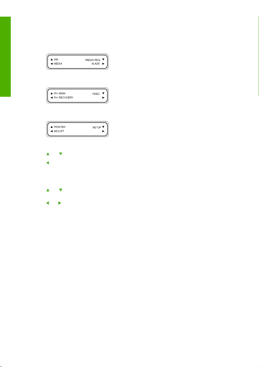
Introduction
Switch between menu group screens with the Shift key.
●
To access a menu, use the arrow key that corresponds to the menu group you want to access.
To switch to the next menu group, press Shift.
To switch to the next menu group, press Shift.
If you select a menu in the menu groups, you will then be able to select an option or submenu:
and keys: change between menus at the same level.
●
key: return to menu group selection.
●
OK key: select a submenu or option so that parameters can be changed.
●
Setting or changing parameters:
and keys: switch between parameters, or increase or decrease a selected value.
●
and keys: change the digit you need to modify when entering a value.
●
Setting a parameter or canceling:
OK key: sets a parameter.
●
Cancel key: cancels an input parameter value and returns to the submenu/option selection.
●
8 Chapter 1 Introduction ENWW
Page 19

Main scroller controls
This section describes the controls provided for the feed and take-up side scroller drive units and the
associated remote foot switches.
Media feed side control panel
NOTE Media advance and rewind always refers to the media travel through the media path
from the feed side to the take-up side of the printer and NOT to the media advance or rewind on
the actual main scrollers.
The media feed controls are located on the control panel next to the main scroller drive unit at the feed side
of the printer. This control panel provides the necessary switches to control the manual advance or rewind
of media through the media path (from the feed side to take-up side of the printer). It also provides and
method of selecting which side of the main scroller to wind the media (inside or outside).
Main scroller drive controls:
1. The white two-position media winding direction switch (1) which is used to select which side of the
main scroller to wind the media on (inside or outside).
2. The black media advance push switch (2), which is used to feed media from the main scroller through
the print path (from the feed side to take-up side of the printer) in the direction set with the winding
direction switch (1). The same operation can also be controlled using the black button on the foot
switch connected at the feed side of the printer.
3. The white media rewind push switch (3), which is used to rewind media to the main scroller through
the print path (from the feed side to take-up side of the printer) back onto the main scroller. The same
operation can also be controlled using the black button on the foot switch connected to the feed side
of the printer.
Introduction
Take-up side control panel
NOTE Media advance and rewind always refers to the media travel through the media path
from the feed side to the take-up side of the printer and NOT to the media advance or rewind on
the actual main scrollers.
ENWW Main scroller controls 9
Page 20

Introduction
The media take-up controls are located on the control panel next to the main scroller (take-up reel) drive
unit at the take-up side of the printer. This control panel provides the necessary switches to control the
manual advance or rewind of media through the media path (from the feed side to take-up side of the
printer). It also provides the method of selecting which side of the main scroller (for take-up) to wind the
media (inside or outside).
Scroller drive controls:
1. The white media rewind push switch (1), which is used to rewind media from the main scroller (take-
up reel) through the print path (from the feed side to take-up side of the printer) in the direction set
with the winding direction switch (3). The same operation can also be controlled using the black button
on the foot switch connected to the feed side of the printer
2. The black media advance push switch (2), which is used to feed media to the main scroller (take-up
reel) through the print path (from the feed side to take-up side of the printer). The same operation can
also be controlled using the black button on the foot switch connected at the feed side of the printer.
3. Three position media winding direction switch (3) which is used to disable the drive and to select which
side of the scroller to wind the media on (inside or outside).
Foot switches
The printer is equipped with two remote foot switches, one to control main scroller drive functions on the
feed side and the other to control the main scroller drive functions on the take-up side. Both foot switches
are identical and contain a black push switch (2) and a white push switch (1). These switches each have
exactly the same functions as their equivalent push switches on the control panels for the main feed and
take-up reel units.
10 Chapter 1 Introduction ENWW
Page 21

Introduction
ENWW Main scroller controls 11
Page 22

The printer's heaters
Introduction
This section describes how to control the printer's heaters used for drying the printed media.
The heater's front panel
The heater's front panel is located on the front of the printer, on the left-hand side. The heater front panel
displays the settings for the Front, Print, and Rear heaters. It can also be used to control the temperature
settings.
1. The display screen, at the top of the panel, shows the target temperature and the current temperature
of each heater.
2. The three On/Off switches turn the three heaters on or off. The three pairs of
to raise or lower the target temperatures of the respective heaters.
Defining heater parameters
1. On the heater front panel press the On/Off key, and the and keys at the same time to enter the
parameter setup mode.
or keys can be used
2. Select a setup parameter using the and keys on the heater front panel and press the On/Off key
on the heater front panel to modify the setup item displayed.
3. Use the
12 Chapter 1 Introduction ENWW
and keys to select the value and press the On/Off key to confirm.
NOTE If you have selected an incorrect setup value, you can press the On/Off key again
to cancel the setting and repeat from step 2.
Page 23
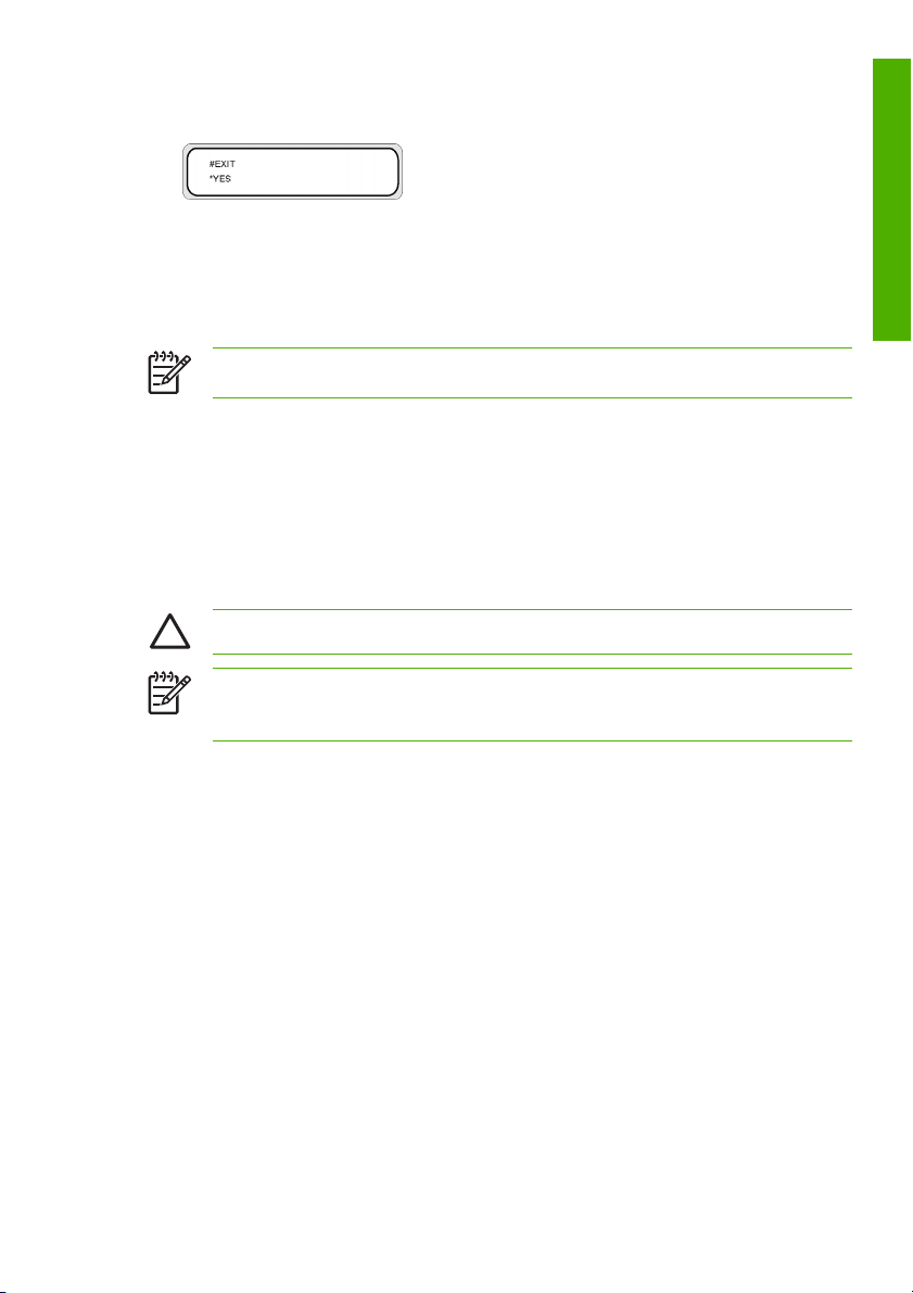
4. To exit the parameter setup mode, scroll to the EXIT option and press the On/Off key to select YES.
5. Press the On/Off key on the heater front panel to confirm.
Connect to a computer
This section describes system configuration and cable connection procedures.
NOTE Before connecting or disconnecting the USB cable, turn the printer OFF.
Choose the system configuration
The following connections are possible.
1. Printer
2. USB interface
3. Printer server (RIP)
Connection procedure
CAUTION Make sure the USB cable is correctly routed to avoid contact with the media.
NOTE Before you connect the USB cable, you should ensure that the RIP is installed so that
the printer can be detected by your operating system. Refer to the instructions that came with
your RIP for installation instructions.
Introduction
ENWW Connect to a computer 13
Page 24

Introduction
Connect a USB cable as follows:
1. Disconnect the USB cable (2) from the rear of your printer if it is already connected.
2. Turn the printer off at the front panel.
3. Power off the printer using the power switch at the rear.
4. Connect a USB cable (2) to the USB connector (1) at the rear of the printer.
5. Use the cable clamps (4) provided, to secure the USB cable (2) to either side, according to the location
of the computer relative to the printer.
6. Connect a USB cable to the USB connector on your computer (3).
7. Power on the printer using the power switch at the rear.
8. Turn the printer on at the front panel.
9. On your computer, select the printer.
Turn the power on/off
WARNING! Only use a 200-240 V AC power supply voltage.
Be sure the printer is well-grounded. Failure to ground the printer may result in electrical shock,
fire, and susceptibility to electromagnetic interference.
CAUTION Always hold the power cord by the plug when connecting and disconnecting from
the power outlet. Never pull on the cord because this may damage it and create risk of fire and
electric shock.
14 Chapter 1 Introduction ENWW
Page 25

Turn on the printer
1. Turn off (position 0) the printer switch (1) on the rear of the printer, and plug one end of the supplied
power cable into the power socket (2) of the printer. Insert the other power plug of the cable into a
suitable electrical outlet.
WARNING! Avoid overloading the printer’s electrical outlet with multiple devices. Use only
the electrical cord supplied by HP with the printer. Do not damage, cut, or repair the power
cord. A damaged power cord causes a risk of fire and electric shock. Replace a damaged
power cord with an HP-approved power cord.
2. Turn on (position 1) the printer switch (1) on the rear of the printer (left hand side viewed from the rear
of the printer).
3. Press the POWER ON/OFF key (1) on the front panel.
Introduction
ENWW Turn the power on/off 15
Page 26
Introduction
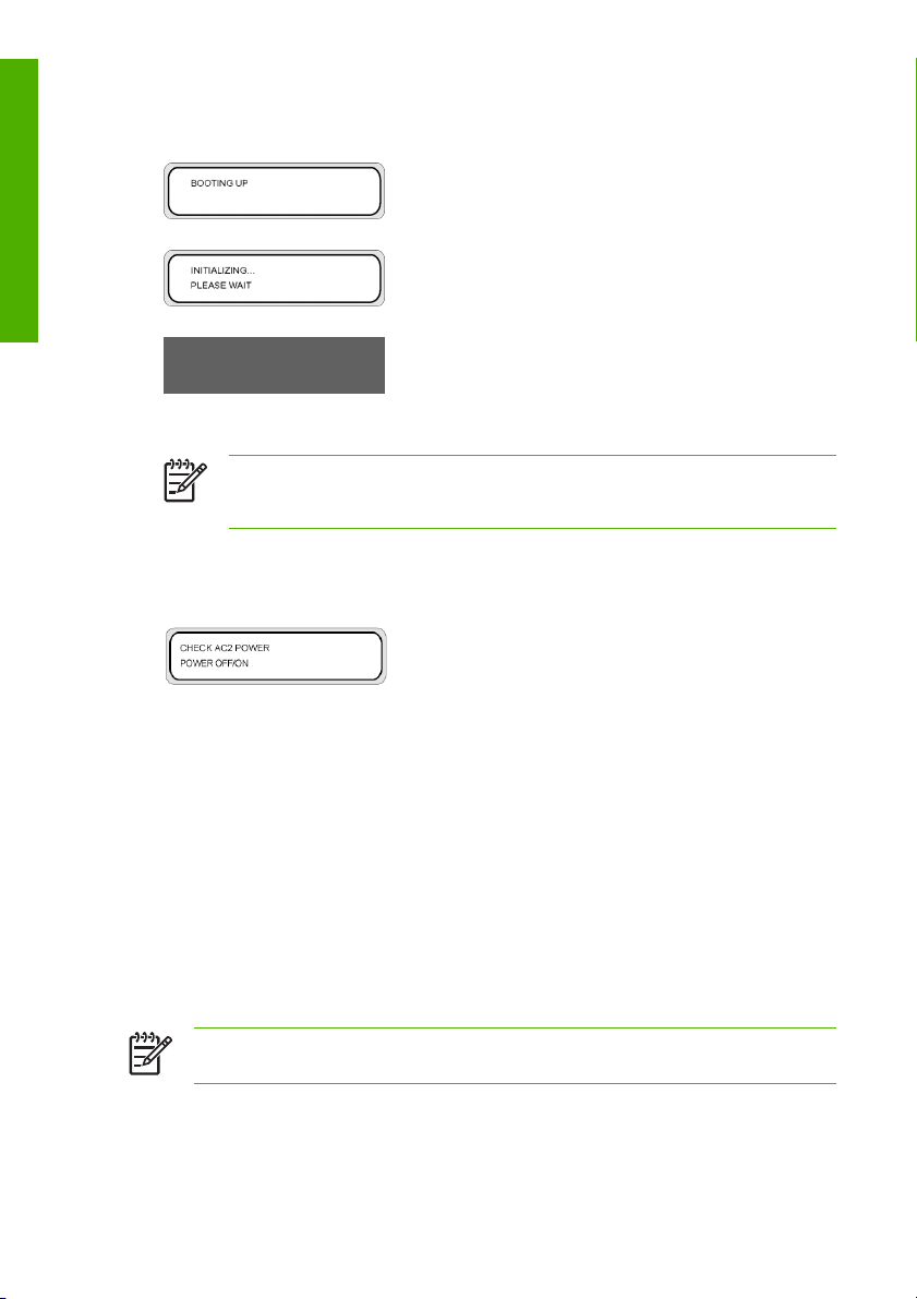
4. When you press power on, the printer performs a power-on self-diagnostic test and the following
messages are displayed on the front panel.
(If a 64" paper roll is loaded).
NOTE Unless there is an emergency, only turn off the printer while PRINTER READY is
displayed on the front panel. Do not turn off the printer while INITIALIZING or PH
RECOVERY is displayed on the front panel to avoid ink drops and damage to the printhead.
5. When you turn the printer power on, the heater front panel display turns on. Turn on the heater power
on/off switch at the rear of the printer to use the heater.
When the heater power is off, the following message is displayed on the front panel.
Turn on the heater
Press the power switch (1) at the rear of the printer (right hand side viewed from the rear of the printer).
NOTE Use the heater switch at the rear of the printer only when turning the printer off completely
for removal, installation, or servicing.
16 Chapter 1 Introduction ENWW
Page 27
Turn the power off
Turn off the printer
WARNING! The printer has an internal clock which allows it to wash the printheads
automatically, flushing some ink through the printhead, which keeps the printheads in good
condition. This is done after the first 20 hours without printing and every 3 days. If the printer is
switched off for a long period, this process does not happen. If the ink does not flow through the
printheads from time to time, the ink will dry inside the nozzles, reaching a point where it is
impossible to recover them and the printhead will fail. This will mean an expensive printhead
replacement.
The printer power switch on the rear of the printer should be used only when the printer is turned
off to move it, to connect it to a computer, or to install or maintain printer parts.
CAUTION If you need to leave the printer unattended for any reason, ensure that the printer
is on, the ink cartridges are full, and the waste ink bottle is empty, so that automatic
maintenance (performed after the first 20 hours without printing and every 3 days) can be
completed successfully for the time you are not present. If needed, install new ink cartridges. The
ink cartridges that you replace can be reused when you return them to your printer, if they still
contain ink.
WARNING! Turn the printer off and unplug the power cable from the power outlet in any of the
following cases; when placing your hands inside the printer, if there is smoke or an unusual smell
coming from the printer, if the printer is making an unusual noise not heard during normal
operation, a piece of metal or a liquid (not part of cleaning and maintenance routines) touches
internal parts of the printer, during an electrical (thunder/lightning) storm, during a power failure.
CAUTION Always hold the power cord by the plug when connecting and disconnecting it from
the power outlet. Never pull on the cord because this may damage it and create risk of fire and
electric shock.
Introduction
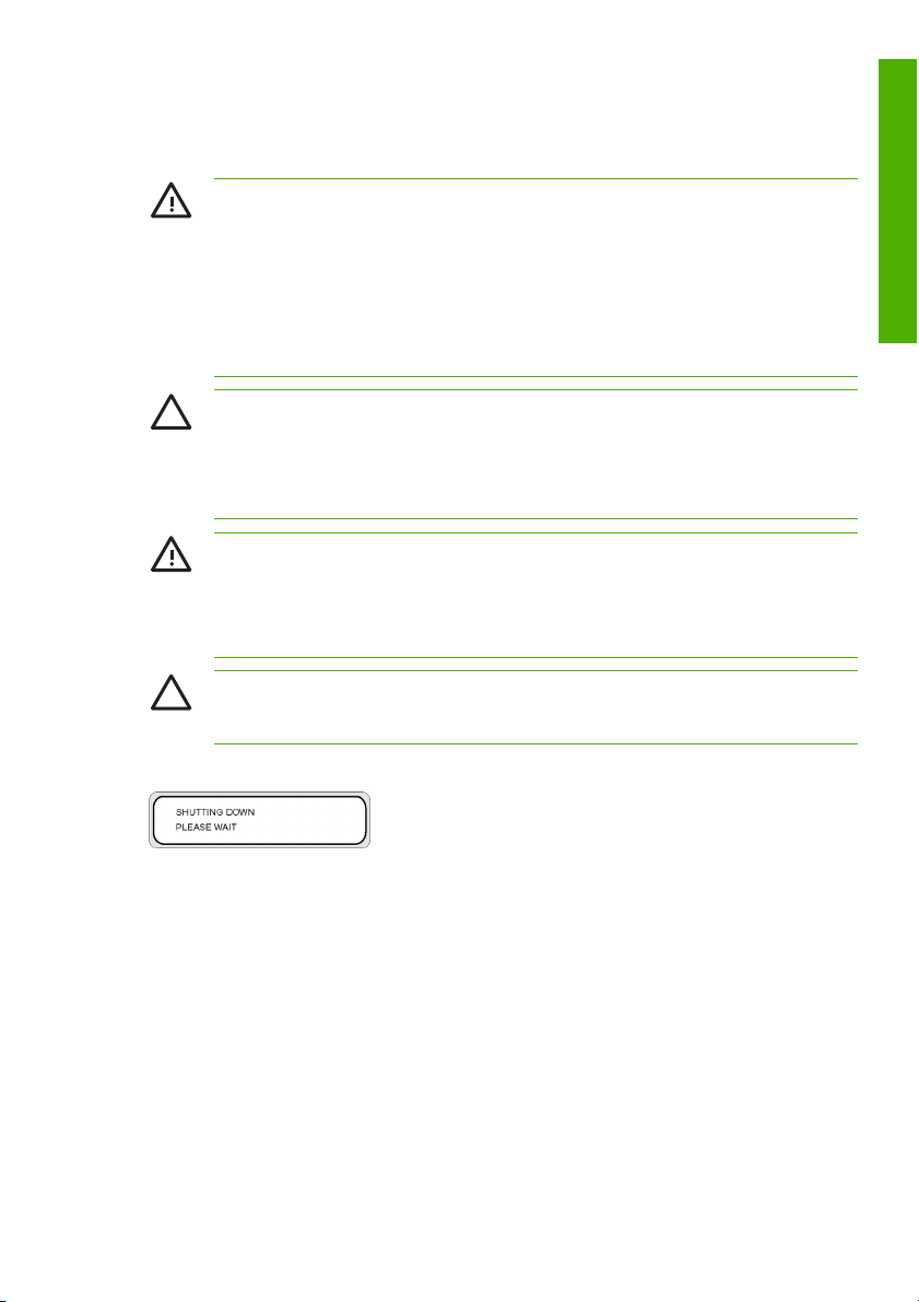
Turn off the power by pressing the power on/off key on the front panel for a couple of seconds.
The front panel displays the message above to indicate that a shutdown process is in progress. After the
process ends, the power is turned off.
If you intend to turn the printer off for a short time, you can avoid the printhead wash operation by pressing
the power on/off key while pressing the Cancel key.
The printhead wash operation is always recommended.
ENWW Turn the power on/off 17
Page 28

Introduction
CAUTION The printer power switch at the rear of the printer should only be used when the
printer is turned off to move it, connect it to a computer, or to install or maintain printer parts.
Turn off the power on/off switch, wait for at least ten seconds, then turn it on again.
The printer washes the printheads 20 hours after the last printing process and every 3 days. We
recommend that the printer power is always left on.
Turn off the heaters
Turn off the heaters by pressing the On/Off keys on the heater front panel.
Under normal conditions of use, you do not need to turn off the heaters using the heater power switch
(1) on the rear of the printer.
NOTE Use the heater switch at the rear of the printer only when turning the printer off completely
for removal, installation, or servicing.
Replace an ink cartridge
CAUTION Always use genuine HP ink cartridges. These have been designed for high-quality
imaging performance and reliable printer operation. Using non-HP inks may cause poor print
quality, printer malfunction, or printer failure. The hazard characteristics of different solvent inks
can vary widely. HP has not conducted product safety testing for non-HP inks with this printer
and is not responsible for any loss or damage that may result if non-HP inks are used.
HP ink cartridges must be installed before the “Install By” date printed on the cartridge. Use of
the ink cartridge 3 months beyond the “Install By” date may cause deterioration in print quality or
a printer malfunction.
NOTE
If an ink cartridge cannot be inserted, check that the color matches the slot. A mechanical key
prevents an ink cartridge from being inserted into the wrong slot.
Do not shake ink cartridges before inserting into the printer.
18 Chapter 1 Introduction ENWW
Page 29

The front panel will advise you when you need to change an ink cartridge.
XX: Ink name (K: Black, Lm: Light magenta, Lc: Light cyan)
XX: Ink name (C: Cyan M: Magenta Y: Yellow)
NOTE The printer will continue to print while you are replacing an ink cartridge.
To replace an empty ink cartridge:
1. Press the clip (1) to open the ink cover (2).
Introduction
ENWW Replace an ink cartridge 19
Page 30

Introduction
2. Remove an ink cartridge (1) from the printer.
3. Insert a new ink cartridge (1) into the printer.
4. Close the ink cover (1).
20 Chapter 1 Introduction ENWW
Page 31

Print Modes
This printer provides 14 different print modes. Choose the print mode to use based on the type of media,
the productivity , and the image quality.
NOTE The recommended print mode for this printer is the “NORMAL” mode. Use the other
modes if productivity and image quality are important.
The FAST print modes should be used when the PC processing the print job has a slow CPU or
has low memory or a small capacity HDD. With these modes the emphasis is on the PC
processing speed and therefor the RIP time is decreased, but the input resolution is 360 x 360
dpi. Consequently, the printed image quality could be degraded compared to the normal modes.
The media width and nest origin settings cannot be saved.
1. “NORMAL” (Productivity + Image quality oriented — 4–pass) This is the standard print mode for this
printer and is the mode you should normally use. It provides a print resolution of 720 x 720 dpi at a
print speed of 16 m2/h. The image quality is processed at high resolution.
2. “H-QUALITY” (Image quality oriented — 8–pass) This mode is used for media that has poor drying
performance or shows noticeable uneven printing in NORMAL mode. The print resolution is the same
as NORMAL mode, 720 x 720 dpi, and the print speed is half the speed of the NORMAL mode.
3. “H-DENSITY” (High density printing — 8–pass) This mode is designed for printing on transparent
media such as FF, transparent vinyl chloride, and other such media, where high density is required.
If media that has poor drying performance is used, unidirectional printing is effective. A solid image
of 100% density is printed at 200% density. The print speed is the same as H-QUALITY.
4. “3 TIMES” (High density printing — 12–pass) This mode is designed for printing on transparent media
such as FF, transparent vinyl chloride, and other such media, where high density is required. A solid
image of 100% density is printed at 300% density. The print speed is three times slower than NORMAL
mode.
5. “H-QUALITY2” (Image quality oriented — 16–pass) This mode is used for media that has poor drying
performance or shows noticeable uneven printing in H-QUALITY mode. The print resolution is the
same as NORMAL mode, 720 x 720 dpi, and the print speed is half the speed of the H-QUALITY
mode.
6. “H-DENSITY2” (High density printing — 16–pass) This mode is designed for printing on transparent
media such as FF, transparent vinyl chloride, and other such media, where high density is required.
Use this mode for media that has poor drying performance or shows noticeable uneven printing in HDENSITY mode. A solid image of 100% density is printed at 200% density. The print speed is half the
speed of the H-DENSITY mode.
7. “DRAFT” (Productivity oriented — 2–pass) This mode provides a print resolution of 360 x 720 dpi at
a print speed of 30 m2/h but with a much lower density than the NORMAL mode. Consequently,
depending on the type of media used, uneven printing may be noticeable. A solid image of 100%
density is printed at 50% density of the NORMAL mode. This mode is very useful for checking layout.
8. “FAST” (Reduced PC processing time— 4–pass) This mode has an equivalent density and the same
print speed as the NORMAL mode.
9. “F-H-QUALITY” (Reduced PC processing time — 8–pass) This mode is used for media that has poor
drying performance or shows noticeable uneven printing in FAST mode but at half the speed of the
FAST mode.
Introduction
ENWW Print Modes 21
Page 32

10. “F-H-DENSITY” (Reduced PC processing time + High density printing — 8–pass) This mode provides
Introduction
equivalent density and print speed to the H-DENSITY mode.
11. “F-3 TIMES” (Reduced PC processing time + High density printing — 12–pass) This mode provides
equivalent density and print speed to the 3–TIMES mode.
12. “F-H-QUAL2” (Reduced PC processing time — 16–pass) This mode is used for media that has poor
drying performance or shows noticeable uneven printing in F-H-QUALITY mode. The print speed is
half the speed of the F-H-QUALITY mode.
13. “F-H-DENS2” (Reduced PC processing time + High density printing — 16–pass) This mode provides
equivalent density to the H-DENSITY mode but at half the speed.
14. “FINE DRAFT” (Productivity + Image quality oriented — 4–pass) This mode provides a print resolution
of 540 x 720 dpi at a print speed of 20 m2/h which is 20% faster than the NORMAL mode. The image
quality for photographs is almost equivalent to that of the NORMAL mode, but a solid image of 100%
density is printed at 75% density of the NORMAL mode. Consequently, if the darkness of the colors
is important, you should use the NORMAL mode.
Safety precautions
The following symbols are used in this manual to ensure the proper use of the printer and to prevent the
printer from being damaged. Follow the instructions marked with these symbols.
WARNING! Failure to follow the guidelines marked with this symbol could result in serious
personal injury or death.
CAUTION Failure to follow the guidelines marked with this symbol could result in minor personal
injury or damage to the product.
General warnings
Only use a 200-240 V AC power supply voltage. Avoid overloading the printer’s electrical outlet with
●
multiple devices.
Be sure the printer is well-grounded. Failure to ground the printer may result in electrical shock, fire,
●
and susceptibility to electromagnetic interference.
Do not disassemble or repair the printer yourself. Do not reinstall the printer in a new location. Call
●
your local HP Service Representative for service.
Use only the electrical cord supplied by HP with the printer. Do not damage, cut, or repair the power
●
cord. A damaged power cord has risk of fire and electric shock. Replace a damaged power cord with
an HP-approved power cord.
Do not allow metal or liquids (except those used in HP Cleaning Kits) to touch the internal parts of the
●
printer. Doing so may cause fire, electric shock, or other serious hazards.
Power OFF the printer and unplug the power cable from the power outlet in any of the following cases:
●
●
●
When placing your hands inside the printer.
If there is smoke or an unusual smell coming from the printer.
22 Chapter 1 Introduction ENWW
Page 33

If the printer is making an unusual noise not heard during normal operation.
●
A piece of metal or a liquid (not part of cleaning and maintenance routines) touches internal parts
●
of the printer.
During an electrical (thunder/lightning) storm.
●
During a power failure.
●
Inks used in the printer and liquids in the HP Cleaning kits contain an organic solvent (ethylene glycol
●
monobutyl ether acetate, CAS No. 112-07-2). Observe all local, state, and federal regulations related
to the handling, use, storage, and disposal of organic solvents.
Ink and fluids used in the Cleaning Kits are combustible. Do not use or store within 8 meters (25 feet)
●
of open flames, sparks, or other sources of ignition.
Do not operate printer within 8 meters (25 feet) of open flames, sparks, or other sources of ignition.
●
Do not smoke within 8 meters (25 feet) of the printer.
Install and operate the printer in a well-ventilated area.
●
The printer installation must meet local, state, and federal regulations on the emissions of volatile
●
organic compounds in the workplace. It is the responsibility of the user to comply with these
regulations. HP recommends that installations use an ink vapor extraction and exhaust system or an
HP Air Purification System. Before installing a system exhausting ink vapors to the outside
atmosphere, consult with your local air quality control authorities. It is your responsibility to comply
with all local, state, and federal air pollution control regulations and building codes.
Avoid contact between ink and skin, eyes, and clothing.
●
Immediately wash skin with soapy water.
●
Remove clothing soaked with ink from contact with skin.
●
Use an approved eye wash station if ink is splashed into eyes and consult a doctor if necessary.
●
If an approved eye wash station is unavailable, flush eyes with cold water and consult a doctor
if necessary.
Do not swallow ink. If swallowed, do not induce vomiting, but seek immediate medical attention.
●
Keep ink cartridges, cleaning kits, and waste ink bottles out of the reach of children.
●
Be sure all operators are trained in the use of emergency equipment such as eye wash stations and
●
fire extinguishers and know where they are located.
Introduction
General cautions
Handle media rolls with care. They can be heavy and difficult to move in confined spaces. In some
●
cases, two people should move and install media rolls. Dropping a media roll could cause personal
injury or damage to the printer.
Allow and maintain adequate space around printer for immediate access to safety equipment such
●
as eye wash stations, fire extinguishers, glove and safety glass dispensers, and fireproof waste
storage containers.
Treat any media, used cleaning and maintenance supplies, and wipes soaked with ink as combustible
●
materials. Handle and dispose of properly.
ENWW Safety precautions 23
Page 34

Introduction
If an Air Purification System is installed, allow adequate space for exhaust hoses from the printer.
●
Locate these hoses and the Air Purification System so that they do not pose a trip hazard or interfere
with the operation of the printer such as loading and unloading media, replacing ink cartridges,
inspecting and replacing the waste ink bottle.
Always hold the power cord by the plug when connecting and disconnecting from the power outlet.
●
Never pull on the cord because this may damage it and create risk of fire and electric shock.
Do not touch heater surfaces in the paper path. This may cause burns.
●
In order to ensure the safe operation of the printer, heed all of the cautions and warnings contained
throughout this manual.
24 Chapter 1 Introduction ENWW
Page 35

Handling precautions
These precautions are recommended to avoid damage to your printer and its components.
Power supply
Only use a 200-240 V AC power supply voltage.
●
Check the printer electrical outlet for proper polarity and grounding before connecting printer. Failure
●
to do so may result in fire and electric shock hazards.
Be sure the printer is well-grounded. Failure to ground the printer may result in electrical shock, fire,
●
and susceptibility to electromagnetic interference.
Avoid overloading the printer’s electrical outlet with multiple devices.
●
Use only the electrical cord supplied by HP with the printer.
●
Printer
Wipe the printer clean with a soft cloth. A cloth moistened with a neutral detergent may be used. Do
●
not allow liquid to enter the printer. This may create risk of fire and electrical shock and cause a
malfunction. Do not clean the printer with benzene or paint thinner. This may damage the paint.
Never touch the printhead nozzles. They can be easily damaged or clogged.
●
Regular inspection and maintenance
Clean the capping unit and wiper blade every day.
●
Check the moisture of the wiper sponge every day.
●
Store the ink system when leaving the printer for a long time (two weeks or more with the power off).
●
Clean and charge the ink system before printing when leaving the printer for a long time.
●
Consumables
Ink inside the ink cartridge is combustible. Do not expose or store near open flames, sparks, or other
●
sources of ignition.
HP ink cartridges must be installed before the “Install By” date printed on the cartridge. Use of the ink
●
cartridge 3 months beyond the “Install By” date may cause deterioration in print quality or a printer
malfunction.
Do not disassemble the ink cartridges. Ink cartridges are intended for single use only.
●
Avoid contact between ink and skin, eyes, and clothing.
●
Immediately wash skin with soapy water.
●
Remove clothing soaked with ink from contact with skin.
●
Use an approved eye wash station if ink is splashed into eyes and consult a doctor if necessary.
●
If an approved eye wash station is unavailable, flush eyes with cold water and consult a doctor
if necessary.
Introduction
ENWW Handling precautions 25
Page 36

Introduction
Use only an HP waste ink bottle. The bottle must be installed according to instructions or waste ink
●
may overflow. An HP waste ink bottle must always be installed before turning the printer ON. Automatic
and manual service cycles produce waste ink that must be contained in an HP waste ink bottle. Do
not remove the cap from its tether to the HP waste ink bottle. The cap is needed to properly seal the
HP waste ink bottle for disposal. Keep the HP waste ink bottle upright. Do not place on tables or
shelves where it could fall. Waste ink is combustible. Keep an HP waste ink bottle containing waste
ink away from open flames, sparks, or other sources of ignition. The level in the HP waste ink bottle
must be checked by visual inspection to prevent overflow. If the waste ink level is above the indication
line, the bottle must be replaced with an empty HP waste ink bottle.
Place a sheet of paper under the HP waste ink bottle on the floor when removing a bottle containing
●
waste ink. This will help clean up any ink spills. If soaked with ink, treat the paper as a combustible
material and dispose of properly.
Do not store HP ink cartridges in direct sunlight. Store HP ink cartridges in a cool, dry place. This
●
prevents deterioration of the ink during storage.
26 Chapter 1 Introduction ENWW
Page 37

2 How do I perform basic media
p
operations?
This chapter explains how to perform basic media operations and guides you through the normal sequence
of tasks required to load roll or sheet media in the printer. It also provides details of any other tasks
associated with manipulation of the media.
The following different tasks are described:
Install a media roll in the printer using the main scroller
●
Install a media roll in the printer using the sub-scroller
●
Use the take-up reel
●
Use the media edge guards
●
Tension bars
●
Use media tube flanges
●
Change the printhead height
●
Remove a media roll from the printer
●
Load cut sheet
●
Perform a manual media feed
●
Use manual nesting
●
Increase/reduce pressure on media
●
Pause or cancel print jobs
●
Offset media loading using the main scroller
●
erations?
o
How do I perform basic media
ENWW 27
Page 38

Install a media roll in the printer using the main scroller
p
CAUTION Do not touch heater surfaces in the paper path. This may cause burns.
Handle media rolls with care. They can be heavy and difficult to move in confined spaces. In some
cases, two people should move and install media rolls. Dropping a media roll could cause
personal injury or damage to the printer.
The printer's front panel messages will guide you through the process of loading media. To install a media
roll:
How do I perform basic media
o
erations?
1. Place the media roll (1) on a suitable table or handling cart (2).
2. Adjust the media roll spacer on the main scroller to a position equivalent to the middle (half the width)
of the media roll you are going to load.
NOTE The media roll spacer stops the weight of the media from causing the roll to sag at
the center.
a. Remove the two locking screws (1) of the media roll spacer.
b. Slide the spacer (3) to the required position on the main scroller (2). There are three positions
available, each of which corresponds to the middle position of different width media rolls.
c. Replace and tighten the two locking screws (1).
28 Chapter 2 How do I perform basic media operations? ENWW
Page 39

3. Install the media roll on the main scroller.
p
a. Verify the media winding direction for the side of the media you are going to print onto, either the
inside of the media (1) or the outside of the media (2).
b. Carefully slide the media tube (2) onto the main scroller (1).
erations?
o
How do I perform basic media
ENWW Install a media roll in the printer using the main scroller 29
Page 40

How do I perform basic media
p
o
erations?
c. Use the media positioning tool (2) to set the correct distance between the media (3) edge and
the main scroller flange (1).
d. Turn the hand-wheel (1) of the main scroller clockwise until it reaches the stop to lock the media
roll to the main scroller.
30 Chapter 2 How do I perform basic media operations? ENWW
Page 41

e. Slide the toothed flange spacer (1) over the main scroller (2) until it is fully engaged with the
p
media tube.
f. Slide the flange stopper (2) over the main scroller until you can align and fully engage it with the
keyway in the flange spacer (1).
g. Fully tighten the locking knob (3) on the flange stopper (2) to lock it to the flange spacer (1) and
the main scroller.
erations?
o
How do I perform basic media
4. Install the main scroller in the printer.
If you are working alone you will need a transport cart (2) to install the main scroller (1).
ENWW Install a media roll in the printer using the main scroller 31
Page 42

How do I perform basic media
p
o
erations?
If there are two people available to load the main scroller (1) by hand, one person will need to use the
scroller handling grip (2) to support the main scroller (1).
a. Carefully position the drive end (1) of the main scroller into the drive slot (2).
32 Chapter 2 How do I perform basic media operations? ENWW
Page 43

b. Carefully lower the opposite end (4) of the main scroller into the scroller retainer (3).
p
5. Adjust the tension bar guide.
a. Loosen the locking knob (2).
b. Move the tension bar guide (1) so that it is aligned with its position label (3).
c. Fully tighten the tension bar guide locking knob (2) to lock the tension bar guide (1).
erations?
o
How do I perform basic media
ENWW Install a media roll in the printer using the main scroller 33
Page 44

6. Open the rear cover (1).
p
How do I perform basic media
o
erations?
7. Move the media edge guards (1) to each end of the platen so they will not be hidden under the media.
8. Lift the media load lever (1).
9. Set the feed direction switch (1) to select the way the media is going to be printed, either on the inside
or the outside of the media.
34 Chapter 2 How do I perform basic media operations? ENWW
Page 45

10. At the front of the printer, use the black media advance switch (2), or the black media advance switch
p
on the foot switch, to feed enough media to insert it into the media feeder.
11. Load the media into the media feeder.
CAUTION Inserting the media obliquely or inserting media with wrinkles could cause a
media jam or skewed feed.
a. Insert the top edge of the media (1) into media feeder (2) while stretching it outwards to prevent
any wrinkling.
b. If the media curls up (1) or down (2), making it hard to insert into the media feeder, place a
backing sheet (3) on or under the curled media to make loading easier.
erations?
o
How do I perform basic media
ENWW Install a media roll in the printer using the main scroller 35
Page 46

How do I perform basic media
p
c. At the front of the printer, use the black media advance switch to feed the media through the
media feeder until it almost reaches the floor.
o
erations?
d. Smooth out the media from the center towards the edges of the platen to tension the center area
of the media.
e. At the front of the printer, use the white rewind switch to rewind the media (1) until it is just
protruding from the rear cover.
NOTE Rewinding the media ensures there is no skew.
36 Chapter 2 How do I perform basic media operations? ENWW
Page 47

f. Lower the media load lever (1).
p
g. Adjust the media edge guards (1) so that they are correctly positioned over the edge of the media.
12. Close the rear cover.
To complete the loading procedure, follow the front panel instructions.
erations?
o
How do I perform basic media
13. Confirm the position of the media edge guards and press the OK key.
The media width checking process starts.
14. Select the media feed position.
a. Select MAIN using the or keys.
b. Press the OK key to confirm the selection.
15. Select the whether or not to use nesting.
ENWW Install a media roll in the printer using the main scroller 37
Page 48

How do I perform basic media
p
o
erations?
a. Select OFF or ON using the or keys.
b. Press the OK key to confirm the selection.
16. Select a media type.
a. Select the media type using the or keys.
There are five preset media types to choose from:
Paper
●
Glossy
●
Matte
●
Banner
●
BLT_B (Backlit)
●
b. Press the OK key to confirm.
NOTE If you wish to select a media type that is currently not available, then you will
need to create a new media type.
c. If required, select the NEW MEDIA ENTRY option using the or key and press the OK key
(Refer to
Manage media types).
Press the Cancel key to return to the SELECT MEDIA menu.
17. Install the tension bar. For full details of how to prepare the tension bars (Refer to
Tension bars).
CAUTION Do not mount the flanges on the tension bar.
a. Adjust the tension bar (1) length to half the media width.
38 Chapter 2 How do I perform basic media operations? ENWW
Page 49

b. At the front of the printer, use the black media advance switch to feed enough media so that you
p
can install the tension bar (1) in the slack area of the media.
NOTE Make sure the tension bar (1) is positioned in the center (widthwise) of the
slack area of the media or the media may not feed smoothly .
NOTE If the media does not roll out smoothly, adjust the tension bar (1) length to be
a little shorter than the width of the media.
18. Install another tension bar (fixing bar) in the tension bar guide at the front of the printer (feed side).
NOTE Refer to Tension bars for full details concerning the adjustment of the tension bar
(fixing bar) length.
a. Adjust the tension bar (1) length to match the width of the media.
b. Fit flanges to each end of the tension bar.
c. Verify that the tension bar guide (2) is located at the correct position for the actual width of the
tension bar and adjust as necessary.
erations?
o
How do I perform basic media
ENWW Install a media roll in the printer using the main scroller 39
Page 50

How do I perform basic media
p
o
erations?
d. Mount the tension bar (1) in the tension bar guides (2).
CAUTION Make sure you install the tension bar with the ESD contact ring at the right
hand end of the tension bar (viewed from the front of the printer).
40 Chapter 2 How do I perform basic media operations? ENWW
Page 51

19. Verify the front panel shows this message and press the OK key.
p
NOTE The next operation will not start if the media is too tight.
The media setting operation starts automatically and shows this message on the front panel.
If the operation completes correctly, the printer returns to the online or offline state.
If it does not complete correctly, the front panel will show an error message. If this occurs, retry the
operation from the step in this procedure where you raised the media load lever.
NOTE The temperature at each end of the platen is slightly lower than the temperature at
the central area. On rare occasions, this temperature difference could cause color density
irregularities at the edges when the media is slow to dry. This color difference is most
apparent when using vinyl chloride (PVC) media. If raising the temperature (Refer to
temperature settings) does not remove the color density irregularity at the edges this can
be solved by using the offset media loading option (Refer to
main scroller). This option moves the media out of the affected area but this option is only
available when using vinyl chloride (PVC) media, on a single roll, with a width of less than
2,000 mm installed on the main scroller.
Offset media loading using the
erations?
o
Heater
How do I perform basic media
ENWW Install a media roll in the printer using the main scroller 41
Page 52

Install a media roll in the printer using the sub-scroller
p
CAUTION Do not touch heater surfaces in the paper path. This may cause burns.
Handle media rolls with care. They can be heavy and difficult to move in confined spaces. In some
cases, two people should move and install media rolls. Dropping a media roll could cause
personal injury or damage to the printer.
The printer's front panel messages will guide you through the process of loading media. To install a media
roll in the printer on the sub-scroller:
How do I perform basic media
1. Place the media roll on a suitable table.
2. Install the media roll on the sub-scroller.
o
erations?
a. Verify the media winding direction for the side of the media you are going to print onto, either the
inside of the media (2) or the outside of the media (1).
b. Carefully slide the media tube (2) onto the sub-scroller (1).
42 Chapter 2 How do I perform basic media operations? ENWW
Page 53

c. Install and tightly lock the flange (1) on the sub-scroller.
p
3. Install the sub-scroller in the printer.
a. Unscrew the attachment knob (2) and remove the tension arm (3) from the sub-scroller center
holder (1).
erations?
o
How do I perform basic media
b. Loosen the locking knob (1) and slide the center sub-scroller holder (2) so that it is outside the
media path.
ENWW Install a media roll in the printer using the sub-scroller 43
Page 54

c. Open the rear cover (1).
p
How do I perform basic media
o
erations?
d. Move the media edge guards (1) so they will not be hidden under the media.
e. Lift the media load lever (1).
44 Chapter 2 How do I perform basic media operations? ENWW
Page 55

f. Place the sub-scroller (2) on the sub-scroller holders (1).
p
4. Adjust the center sub-scroller holder position.
a. Slide the center sub-scroller holder (1) as close as possible to the sub-scroller flange.
b. Push the center sub-scroller holder (1) towards the rear of the printer (this ensures it is seated
squarely).
c. Fully tighten the center sub-scroller holder locking knob (2).
erations?
o
How do I perform basic media
ENWW Install a media roll in the printer using the sub-scroller 45
Page 56

How do I perform basic media
p
o
erations?
5. Load the media.
a. Feed the media (1) through the media feeder until it almost reaches the floor.
b. Rotate the sub-scroller (1) by hand to rewind the media (2) until it is just protruding from the rear
cover.
NOTE Use your hand to restrain the central area of the media to eliminate any slack.
46 Chapter 2 How do I perform basic media operations? ENWW
Page 57

c. Lower the media load lever (1).
p
d. Adjust the media edge guards (1) so that they are correctly positioned over the edge of the media.
6. Close the rear cover (1).
erations?
o
How do I perform basic media
To complete the loading procedure, follow the front panel instructions.
7. Select the media feed position.
ENWW Install a media roll in the printer using the sub-scroller 47
Page 58

How do I perform basic media
p
o
erations?
a. Select SUB using the or keys.
b. Press the OK key to confirm the selection.
8. Select the whether or not to use nesting.
a. Select OFF or ON using the or keys.
b. Press the OK key to confirm the selection.
9. Select a media type.
a. Select the media type using the or keys.
There are five preset media types to choose from:
Paper
●
Glossy
●
Matte
●
Banner
●
BLT_B (Backlit)
●
b. Press the OK key to confirm.
NOTE If you wish to select a media type that is currently not available, then you will
need to create a new media type.
c. If required, select the NEW MEDIA ENTRY option using the or key and press the OK key
(Refer to
Manage media types).
Press the Cancel key to return to the SELECT MEDIA menu.
48 Chapter 2 How do I perform basic media operations? ENWW
Page 59

10. The media setting operation starts automatically and shows this message on the front panel.
p
If the operation completes correctly, the printer returns to the online or offline state.
If it does not complete correctly, the front panel will show an error message. If this occurs, retry the
operation from the step in this procedure where you raised the media load lever.
NOTE The temperature at each end of the platen is slightly lower than the temperature at
the central area. On rare occasions, this temperature difference could cause color density
irregularities at the edges when the media is slow to dry. This color difference is most
apparent when using vinyl chloride (PVC) media. If raising the temperature (Refer to
temperature settings) does not remove the color density irregularity at the edges this can
be solved by using the offset media loading option (Refer to
main scroller). This option moves the media out of the affected area but this option is only
available when using vinyl chloride (PVC) media, on a single roll, with a width of less than
2,000 mm installed on the main scroller.
Use the take-up reel
1. Adjust media roll spacer on the main scroller to a position equivalent to the middle (half the width) of
the media tube you are going to load. There are three positions available to suit different widths of
media.
NOTE The media roll spacer stops the weight of the media from causing the roll to sag at
the center.
a. Remove the two locking screws (1) of the media roll spacer.
b. Slide the spacer (3) to the required position on the main scroller (2). There are three positions
available, each of which corresponds to the middle position of different width media rolls.
c. Replace and tighten the two locking screws (1).
Heater
Offset media loading using the
erations?
o
How do I perform basic media
2. Install a suitable empty media tube on the main scroller.
ENWW Use the take-up reel 49
Page 60

How do I perform basic media
p
o
erations?
NOTE Position the tension bar guide so it does not cause any mechanical interference.
3. Use the media positioning tool (2) to set the correct distance between the edge of the empty media
tube (3) and the main scroller flange (1).
4. Turn the hand-wheel (1) of the main scroller clockwise until it reaches the stop, to lock the media tube
to the main scroller.
50 Chapter 2 How do I perform basic media operations? ENWW
Page 61

5. Slide the flange spacer (1) over the main scroller (2) until it is fully engaged with the empty media
p
tube.
6. Slide the flange stopper (2) over the main scroller until you can align and fully engage it with the keyway
in the flange spacer (1).
7. Fully tighten the knob (3) on the flange stopper (2) to lock it to the flange spacer (1) and the main
scroller.
erations?
o
How do I perform basic media
ENWW Use the take-up reel 51
Page 62

How do I perform basic media
p
o
erations?
8. At the rear of the printer, set the white media winding direction switch (1) to the OFF (center) position.
WARNING! If you do not set the media winding direction switch to the OFF position before
installing the take-up reel you risk trapping your hands in the drive mechanism.
9. Install the main scroller (take-up reel) in the printer.
a. Carefully position the drive end of the main scroller (1) into the drive slot on the printer.
b. Carefully lower the opposite end of the main scroller (1) into the scroller retainer.
52 Chapter 2 How do I perform basic media operations? ENWW
Page 63

10. Use the front panel feed menu to feed the media (1) through the media feeder far enough for it to be
p
taken-up on the main scroller (take-up reel).
11. Attach media to the media tube on the main scroller (take-up reel).
a. Confirm the take-up direction, inside or outside.
b. Attach the edge of the media to the media tube on the take-up reel using adhesive tape (1) at
center the center position.
c. Make sure the media is perfectly straight and then secure the outer edges with adhesive tape
(1).
erations?
o
How do I perform basic media
ENWW Use the take-up reel 53
Page 64

How do I perform basic media
p
o
erations?
12. Verify that the tension bar guide (1) is located within the light sensor (2) receiving area and adjust as
necessary.
13. At the rear of the printer, set the white media winding direction switch (1) to the correct position for
the way the media is to be taken-up, inner take-up (A) or outer take-up (B).
14. Use the front panel feed menu to feed enough media to provide two full turns on the take-up reel
(Refer to
Perform a manual media feed).
54 Chapter 2 How do I perform basic media operations? ENWW
Page 65

15. At the rear of the printer, set the white media winding direction switch (1) to the OFF (center) position.
p
16. Turn the take-up reel by hand (in the required direction—for inner or outer take-up) until two full turns
have been wound onto the tube.
17. Use the front panel feed menu to feed enough additional media through the media feeder to create a
slack area (approximately 30 cm) in the media sufficient to install the tension bar (Refer to
manual media feed).
18. Position the tension bar (1) in its guides (2) in the slack area of the media.
CAUTION Make sure you install the tension bar with the ESD contact flange at the right
hand end of the tension bar (viewed from the rear of the printer).
Perform a
erations?
o
How do I perform basic media
ENWW Use the take-up reel 55
Page 66

How do I perform basic media
p
o
erations?
19. At the wiper end of the tension bar (1), adjust the take-up bar flange (3) position for the width of the
media, leaving a 2 mm gap, and lock it in position with the two O-rings (2).
20. At the capping end, adjust the take-up flange (1) on the tension bar (2) so it is positioned against the
edge of the media (without the fixing O-rings).
21. At the rear of the printer, set the white media winding direction switch (1) to the correct position for
the direction the media is to be taken-up, inner take-up (A) or outer take-up (B).
56 Chapter 2 How do I perform basic media operations? ENWW
Page 67

22. If you are using vinyl chloride (PVC) media (1), do not use the full tension bar as explained previously.
p
Instead, adjust the tension bar (2) length to approximately half the width of the media and position it
in the slack area without the flanges.
NOTE If you are using vinyl chloride (PVC) media, it is recommended to use media tube
flanges in order to prevent weaving. Refer to
Use the media edge guards
Set the media edge guards (1) on the right and left of the media in the printing path to reduce the risk of
printhead crashes.
NOTE When using the media edge guards, the right and left margins increase from 5 mm to 10
mm.
If you need to activate or deactivate the use of the media edge guards, you can do it through the front panel
by accessing the MEDIA REG menu:
1. Press the Online key.
Use media tube flanges
erations?
o
How do I perform basic media
ENWW Use the media edge guards 57
Page 68

How do I perform basic media
p
2. Press the key to see MEDIA REG menu options.
3. Select the media with which you want to use or not use the media edge guards, and press the OK
key.
This setting will only apply to the selected media.
4. Scroll to USE EDGE GUARD using the
or keys and press the OK key.
o
erations?
Tension bars
5. Select YES or NO and press OK to confirm.
You use the same tension bars on the media feed side and take-up side of the printer but in order to
eliminate the possible of the build up of any electrostatic energy different flanges are used for each. The
tension bars are provided in three sets, two with flanges and one without flanges providing the following
total parts:
3 x long tension (1) bar with male joints at each end (123 cm)
●
3 x medium tension (2) bar with one male and one female joint (61 cm)
●
6 x short tension bars (3) with one male and one female joint (41 cm)
●
6 x standard flanges (4)
●
2 x take-up flanges (5)
●
2 x fixing rings (6)
●
1 x feed side ESD contact ring (7)
●
1 x take-up side ESD flange (8)
●
58 Chapter 2 How do I perform basic media operations? ENWW
Page 69

Feed side tension bar assembly
p
The tension bars screw into one another to make a total length of 266 cm if all four are used. The long
tension bar, with two male joints, must always be used, with or without additional medium and short tension
bars because it has male joints which are required for fitting flanges.
If the tension bar is going to be installed in the slack area of the media, use one or more tension bars
●
(3) to create a total length that is equivalent to half the width of the media and do not install the flanges
(1) and ESD contact ring (2).
If the tension bar is going to be installed in the tension bar guides, use the required tension bars to
●
create a total length that is equivalent to the width of the printer, install two standard flanges (1) at the
left end and an ESD contact ring (2) and another standard flange (1) at the right hand end.
erations?
o
How do I perform basic media
Take-up side assembly method
The tension bars screw into one another to make a total length of 266 cm, if all four are used. The long
tension bar, with two male joints, must always be used, with or without additional medium and short tension
bars because it has male joints which are required for fitting flanges.
ENWW Tension bars 59
Page 70

How do I perform basic media
p
o
erations?
If the tension bar is going to be installed in the slack area of the media, use one or more tension bars
●
(3) to create a total length that is equivalent to half the width of the media and do not install the flanges
(1), ESD flange (4) and the take-up flanges (3) and their associated fixing rings (2).
If the tension bar is going to be installed in the tension bar guides, use the required tension bars to
●
create a total length that is equivalent to the width of the printer, at the left hand end install one standard
flange (1) and one ESD flange (4) , slide the take-up flanges (3) and their associated fixing rings (2)
onto the tension bar, and install two standard flanges (1) at the right hand end.
CAUTION You must always clean the fixing ring and tension bar using alcohol to remove
any dirt because this could cause the fixing ring to become displaced during take-up,
resulting in the media being wound unevenly.
Install the flanges at each end of the tension bar. When you insert the tension bar into the flange, align
●
the cutouts in the flange with the screw heads in the tension bar.
NOTE For vinyl chloride (PVC) media assemble the tension bar in the same way as for
the feed side (no flanges, take-up flanges, or fixing rings).
Use media tube flanges
You use the media tube flanges to take-up media such as vinyl chloride (PVC) and FF which are both
susceptible to weaving. In some cases special spacers are required to install the media tube flanges. These
special spaces are needed when the media tube cannot be fully engaged with the end flanges because
the inside diameter of the tube is too small.
The following flanges are supplied:
3 x rubber spacer A (1)
●
3 x rubber spacer B (2)
●
1 x rubber spacer C (3)
●
60 Chapter 2 How do I perform basic media operations? ENWW
Page 71

4 x media tube flanges (4)
p
●
Install the media tube flanges
This procedure describes how to install the media tube flanges on the main scroller (take-up reel).
1. Adjust the media tube spacer position to suit the media width.
2. Prepare the media tube and slide it onto the scroller.
3. Install the rubber spacer C (1) on the scroller (2).
erations?
o
How do I perform basic media
ENWW Use media tube flanges 61
Page 72

How do I perform basic media
p
o
erations?
4. Put the rubber spacer A (1) on the flange spacer (2).
5. Engage the flange spacer and rubber spacer A (2) with the flange stopper and mount them both on
the on the scroller (1).
If the internal diameter of the media tube is too small to fully engage the flange spacer and rubber
spacer A (2), resulting in a large space between flange spacer and the edge of the media tube, use
the rubber spacer B (3) to fill this gap.
6. Temporarily install the media tube flanges (1) on the rubber spacers. You will adjust the position of
these later according to the actual media width.
7. At the rear of the printer, set the white media winding direction switch to the OFF position.
62 Chapter 2 How do I perform basic media operations? ENWW
Page 73

8. Refer to Install a media roll in the printer using the main scroller and install the main scroller in the
p
printer.
9. Use the front panel feed menu to feed the media through the media feeder far enough for it to be
taken-up on the take-up reel.
10. Use adhesive tape to attach the edge of each media to the media tube on the take-up reel. Attach the
center of the media first then the outer edges, making sure the media is straight.
Inner take-up is recommended because the amount of media wound with outer take-up is less, which
could cause abrasion to the printed surface when the diameter of the wound media becomes large,
consequently degrading the image quality.
11. Adjust the positions of the media tube flanges to match the media width.
12. Tighten the three locking screws (1) on each media tube flange to lock the flanges in position. Use
the indications on the labels to equally tighten the locking screws.
erations?
o
How do I perform basic media
13. At the rear of the printer, set the white media winding direction switch (1) to match the required take-
up winding direction, inner (A) or outer (B).
ENWW Use media tube flanges 63
Page 74

Change the printhead height
p
You can increase or reduce the printhead height depending on the thickness of the media you are using.
Two tasks must be performed to change the printhead height:
Mechanical height adjustment on the printhead carriage.
●
Firmware height adjustment through the front panel.
●
To change the printhead height:
1. Press the Online key.
How do I perform basic media
o
erations?
2. Press the Shift key to display the PH. MAIN menu.
3. Press the key to enter the PH. MAIN menu.
4. Scroll to PH HEIGHT ADJUSTon the front panel and press OK to confirm.
The following message is displayed.
The following message is displayed.
64 Chapter 2 How do I perform basic media operations? ENWW
Page 75

5. Open the cap cover (3) and loosen the printhead fixing screws (1) using the long screwdriver provided
p
with your printer inserted through the hole in the chassis (2).
6. Change the height of the printhead by lifting the printhead height lever (1) to lower the printhead, or
by lowering it to lift the printhead.
7. Tighten the printhead fixing screws, previously loosened, using the long screwdriver provided with
your printer.
NOTE Tighten the printhead fixing screws while applying slight downward pressure on the
carriage using your hand.
8. Close the rear cover.
erations?
o
How do I perform basic media
ENWW Change the printhead height 65
Page 76

To change the printhead height on the front panel:
p
1. Press the Online key.
2. Press the key to display the MEDIA REG menu.
How do I perform basic media
3. Scroll to the PH HEIGHT VAL option and press the OK key.
o
erations?
4. Select NORMAL or HIGH, according to the mechanical change you have made, and press the OK
key.
Parameters: NORMAL (default) or HIGH (for thick media).
NOTE When the printhead height is changed, a gap in printing may occur in bidirectional
printing. Adjust the correction value for bidirectional printing (Refer to
adjustment).
Remove a media roll from the printer
To remove a media roll from the printer:
1. Remove the tension bars from the media feed side and take-up side of the printer.
2. If necessary, cut the media.
CAUTION A mesh is installed on the media feed side and take-up side of the printer so
that the media does not adhere to the platen. Do not remove this netting. When cutting the
media, take care not to damage the netting.
Perform printhead position
66 Chapter 2 How do I perform basic media operations? ENWW
Page 77

3. Lift the media load lever (1).
p
4. Use the white rewind switch on the media feed side of the printer to rewind the media back onto the
main scroller.
5. Remove the main scroller from the printer and place it on a suitable table.
6. Loosen the knob (3) and remove the flange stopper (2) and the flange spacer (1) from the main scroller.
7. Remove the scroller from the media roll.
a. Rotate the hand wheel counterclockwise (1).
b. When a gap is visible between the hand wheel and the main scroller shaft, remove the main
scroller from the media roll.
erations?
o
How do I perform basic media
ENWW Remove a media roll from the printer 67
Page 78

How do I perform basic media
p
Load cut sheet
o
erations?
The printer's front panel messages will guide you through the process of loading media. To load cut sheet:
1. Open the rear cover and slide the media edge guards (1) to each end of the platen.
2. Close the rear cover.
68 Chapter 2 How do I perform basic media operations? ENWW
Page 79

3. Lift the media load lever (1).
p
4. Feed the media until a beep sounds from the media feeder (about 200 mm).
NOTE If you have problems loading media, feed the media into the printer by holding both
edges of the media.
Take care that the media does not curl inside the rear cover and that the media edge guards
are not obstructing the media path.
erations?
o
How do I perform basic media
ENWW Load cut sheet 69
Page 80

5. Open the rear cover and adjust the media edge guards (1).
p
How do I perform basic media
o
erations?
6. Lower the media load lever (1).
7. Confirm the position of the media edge guards and press the OK key.
To complete the loading procedure, follow the front panel instructions.
8. Select cut sheet.
a. Select SHEET using the or keys.
b. Press the OK key to confirm.
9. Select a media type.
70 Chapter 2 How do I perform basic media operations? ENWW
Page 81

a. Select the media type using the or keys.
p
There are five preset media types to choose from:
Paper
●
Glossy
●
Matte
●
Banner
●
BLT_B (Backlit)
●
b. Press the OK key to confirm.
NOTE If you wish to select a media type that is currently not available, then you will
need to create a new media type.
erations?
o
c. If required, select the NEW MEDIA ENTRY option using the or key and press the OK key
(Refer to
Manage media types).
Press the Cancel key to return to the SELECT MEDIA menu.
10. The media will be loaded automatically.
If an error message is displayed, remove the media and repeat the task.
Perform a manual media feed
This section describes how to feed media manually through the printing path, for example to use cut sheets
without causing skew.
1. Press the Online key.
ENWW Perform a manual media feed 71
How do I perform basic media
Page 82

2. Press the Shift key to display the FEED menu.
p
3. Hold down the key.
How do I perform basic media
While the key is pressed, roll media advances. If cut sheet is loaded, it is discharged.
4. When the
o
erations?
Use manual nesting
When printing a small-sized image (2), such as A4, on a 64-inch width roll, a large area of media (1) is left
blank. You can rewind the roll and nest an image in the blank area using the Origin Point Setting feature.
key is released, media feeding stops and the menu group is displayed.
NOTE The manual nesting feature can be used only with roll media.
72 Chapter 2 How do I perform basic media operations? ENWW
Page 83

To use manual nesting:
p
1. Lift the media load lever.
2. Rewind the media (1).
A. Blank area
NOTE Rewind the media only when the image is dry, to avoid smearing.
3. The front panel instructs you to load media. Load the media.
erations?
o
How do I perform basic media
ENWW Use manual nesting 73
Page 84

How do I perform basic media
p
o
erations?
4. Lower the media load lever.
5. Select NEST in the SELECT MEDIA menu and press the OK key.
NOTE In the next steps, use the MEDIA WIDTH setting if you cut the media to remove the
image that was previously printed. Use the NEST ORIGIN setting if you have not cut the
media and to start printing from a point that excludes the previously printed image.
6. Enter the media width and press the OK key. The media width previously detected is displayed. (Media
width input range: 290 to 1635 mm)
74 Chapter 2 How do I perform basic media operations? ENWW
Page 85

7. Input the nest origin point (print offset value for media width: origin point).
p
The nest origin setting is displayed.
The start position for printing is modified if either the media width or the nest origin is set.
A. Nest origin point
B. Print margin including the image
C. Media width input value
8. Select YES or NO.
Select YES to increase the available area for printing. Rewind the media back onto the roll
●
ensuring the media is present between the media output sensor and media rollers. (The first 20
– 30 mm from the front edge will not be available for printing).
erations?
o
How do I perform basic media
Select NO if the area from the media output sensor position to the print start position (the media
●
rollers) will not be available for printing.
NOTE Ensure the media is aligned with the vertical guide line before loading.
ENWW Use manual nesting 75
Page 86

9. Select a media type again.
p
Shift
How do I perform basic media
NOTE Ensure front, right, and left margins are sufficient as you rewind the media manually.
The media width and nest origin settings cannot be saved.
o
erations?
Increase/reduce pressure on media
The media pressure lever allows you to change the pressure on the media exerted by the media
transmission roller. This can be used to solve skew with certain types of media. To increase/reduce pressure
on media:
NOTE The low pressure position should be used for textile type media.
Pull the lever to the front and lift or lower to change the pressure on the media. Down for normal
pressure and up for low pressure.
76 Chapter 2 How do I perform basic media operations? ENWW
Page 87

Pause or cancel print jobs
p
You can pause and cancel printing from the rear of the printer. This may be useful if there are problems
with media output from the rear of the printer.
Tip We recommend that you always pause or cancel printing through your software RIP.
1. Print Pause/Restart (1) and Cancel (2) buttons.
2. While printing, press the Pause/Restart (1) button to interrupt printing and the Restart button to
continue printing after an interruption.
3. To restart printing, press the Print Pause/Restart (1).
4. Press the Cancel button (2) to cancel printing.
erations?
o
How do I perform basic media
ENWW Pause or cancel print jobs 77
Page 88

Offset media loading using the main scroller
p
The temperature at each end of the platen is slightly lower than the temperature at the central area. On
rare occasions, this temperature difference could cause color density irregularities at the edges when the
media is slow to dry. This color difference is most apparent when using vinyl chloride (PVC) media. If raising
the temperature does not remove the color density irregularity at the edges this can be solved by using the
offset media loading option. This option moves the media out of the affected area but this option is only
available when using vinyl chloride (PVC) media, on a single roll, with a width of less than 2,000 mm installed
on the main scroller.
CAUTION Do not touch heater surfaces in the paper path. This may cause burns.
How do I perform basic media
o
erations?
Handle media rolls with care. They can be heavy and difficult to move in confined spaces. In some
cases, two people should move and install media rolls. Dropping a media roll could cause
personal injury or damage to the printer.
NOTE Offset media loading does not prevent color density irregularities that appear across the
whole width of the media. In such case, select a print mode with a higher pass count.
NOTE Offset media loading is only available for vinyl chloride (PVC) media installed on the main
scroller. It is not available for any of the other media loading methods.
The printer's front panel messages will guide you through the process of loading media. To install a media
roll:
1. Place the media roll (1) on a suitable table or handling cart (2).
2. Remove the media roll spacer from the main scroller.
a. Remove the two locking screws (1) of the media roll spacer.
b. Slide the spacer (3) off the main scroller (2).
78 Chapter 2 How do I perform basic media operations? ENWW
Page 89

3. Slide the flange stopper (1) onto the main scroller (2).
p
4. Slide the flange spacer (1) onto the main scroller (2).
erations?
o
How do I perform basic media
ENWW Offset media loading using the main scroller 79
Page 90

How do I perform basic media
p
o
erations?
5. Position the media roll spacer on the main scroller to a position equivalent to the middle (half the width)
of the media roll you are going to load.
NOTE The media roll spacer stops the weight of the media from causing the roll to sag at
the center.
a. Replace the media roll spacer (3) onto the main scroller (2).
b. Slide the spacer (3) to the required position on the main scroller (2). There are three positions
available, each of which corresponds to the middle position of different width media rolls.
c. Replace and tighten the two locking screws (1).
6. Install the media roll on the main scroller.
a. Verify the media winding direction for the side of the media you are going to print onto, either the
inside of the media (2) or the outside of the media (1).
80 Chapter 2 How do I perform basic media operations? ENWW
Page 91

b. Carefully slide the media tube (2) onto the main scroller (1). Do not tighten the locking knob at
p
this stage.
c. Slide the toothed flange spacer (1) over the main scroller (2) until it is fully engaged with the
media tube.
erations?
o
How do I perform basic media
ENWW Offset media loading using the main scroller 81
Page 92

How do I perform basic media
p
o
erations?
d. Slide the flange stopper (2) over the main scroller until you can align and fully engage it with the
keyway in the flange spacer (1). Do not tighten the locking knob at this stage.
7. Install the main scroller in the printer.
If you are working alone you will need a transport cart (2) to install the main scroller (1).
If there are two people available to load the main scroller (1) by hand, one person will need to use the
scroller handling grip (2) to support the main scroller (1).
82 Chapter 2 How do I perform basic media operations? ENWW
Page 93

a. Carefully position the drive end (1) of the main scroller into the drive slot (2).
p
b. Carefully lower the opposite end (4) of the main scroller into the scroller retainer (3).
8. Align the edge of the media (2) with the label (1) on the printer.
erations?
o
How do I perform basic media
ENWW Offset media loading using the main scroller 83
Page 94

How do I perform basic media
p
9. Align and engage the flange stopper (2) with the keyway in the flange spacer (3) and fully tighten the
locking knob (1) to lock it to the flange spacer (1) and the main scroller.
o
erations?
10. Align and engage the flange stopper (2) with the keyway in the flange spacer (1) and fully tighten the
locking knob (3) to lock it to the flange spacer (1) and the main scroller.
11. Adjust the tension bar guide.
a. Loosen the locking knob (2).
b. Move the tension bar guide (1) so that it is aligned with its position label (3).
84 Chapter 2 How do I perform basic media operations? ENWW
Page 95

c. Fully tighten the tension bar guide locking knob (2) to lock the tension bar guide (1).
p
12. Open the rear cover (1).
13. Move the media edge guards (1) to each end of the platen so they will not be hidden under the media.
erations?
o
How do I perform basic media
ENWW Offset media loading using the main scroller 85
Page 96

How do I perform basic media
p
o
erations?
14. Lift the media load lever (1).
15. Set the feed direction switch (1) to select the way the media is going to be printed, either on the inside
or the outside of the media.
16. At the front of the printer, use the black media advance switch (2), or the black media advance switch
on the foot switch, to feed enough media to insert it into the media feeder.
17. Load the media into the media feeder.
86 Chapter 2 How do I perform basic media operations? ENWW
Page 97

CAUTION Inserting the media obliquely or inserting media with wrinkles causes a media
p
jam or skewed feed.
a. Insert the top edge of the media (1) into media feeder (2) while stretching it outwards to prevent
any wrinkling.
b. If the media curls up (1) or down (2), making it hard to insert into the media feeder, place a
backing sheet (3) on or under the curled media to make loading easier.
c. At the front of the printer, use the black media advance switch to feed the media through the
media feeder until it almost reaches the floor.
d. Smooth out the media from the center towards the edges of the platen to tension the center area
of the media.
erations?
o
How do I perform basic media
ENWW Offset media loading using the main scroller 87
Page 98

How do I perform basic media
p
e. Use the white rewind switch to rewind the media (1) until it is just protruding from the rear cover.
o
erations?
f. Lower the media load lever (1).
18. Change the print mode to offset media loading.
a. When you lower the media load lever the front panel shows the following message.
b. Press and hold the Shift key for more than two seconds to change the media loading option to
offset media loading.
c. Press the Ok to confirm the media loading option to offset media loading.
88 Chapter 2 How do I perform basic media operations? ENWW
Page 99

19. Adjust the media edge guards (1) so that they are correctly positioned over the edge of the media.
p
20. Confirm the position of the media edge guards and press the OK key.
The media width checking process starts.
21. Select the media feed position.
erations?
o
a. Select MAIN using the or keys.
b. Press the OK key to confirm the selection.
22. Select a media type.
a. Select the media type using the or keys.
There are five preset media types to choose from:
Paper
●
Glossy
●
Matte
●
Banner
●
BLT_B (Backlit)
●
ENWW Offset media loading using the main scroller 89
How do I perform basic media
Page 100

How do I perform basic media
p
b. Press the OK key to confirm.
NOTE If you wish to select a media type that is currently not available, then you will
need to create a new media type.
c. If required, select the NEW MEDIA ENTRY option using the or key and press the OK key
(Refer to
Manage media types).
Press the Cancel key to return to the SELECT MEDIA menu.
23. Install the tension bar. For full details of how to prepare the tension bars (Refer to
Tension bars).
o
erations?
CAUTION Do not mount the flanges on the tension bar.
a. Adjust the tension bar (1) length to half the media width.
b. At the front of the printer, use the black media advance switch to feed enough media so that you
can install the tension bar (1) in the slack area of the media.
NOTE Make sure the tension bar (1) is positioned in the center (widthwise) of the
slack area of the media or the media may not feed smoothly .
NOTE If the media does not roll out smoothly, adjust the tension bar (1) length to be
a little shorter than the width of the media.
24. Install another tension bar (fixing bar) in the tension bar guide at the front of the printer (feed side).
NOTE Refer to Tension bars for full details concerning the adjustment of the tension bar
(fixing bar) length.
a. Adjust the tension bar (1) length to match the width of the media.
b. Fit flanges to each end of the tension bar.
90 Chapter 2 How do I perform basic media operations? ENWW
 Loading...