

Page 1

Parts and Diagrams7
Right Hand Covers 7-2
Left Hand Covers 7-4
Center Covers 7-6
Electronics Module 7-8
Control Panels 7-10
Carriage Assembly 7-12
Scan-Axis Assemblies 7-14
Paper Path Assemblies 7-16
Media Entry Assemblies 7-18
Take-Up-Reel Assemblies 7-20
Capping Assemblies 7-22
Wiping Assemblies 7-24
Ink Supply and Subtank Tubes 7-26
Ink Supply and Subtank Assemblies 7-28
Printer Stand and Waste Bottle 7-30
Media Feed and TUR Sensors 7-32
Accessories 7-34
Service Tools 7-36
7
HP Designjet 10000s Series Printer Service Manual
7-1
Page 2
Parts and Diagrams
Right Hand Covers
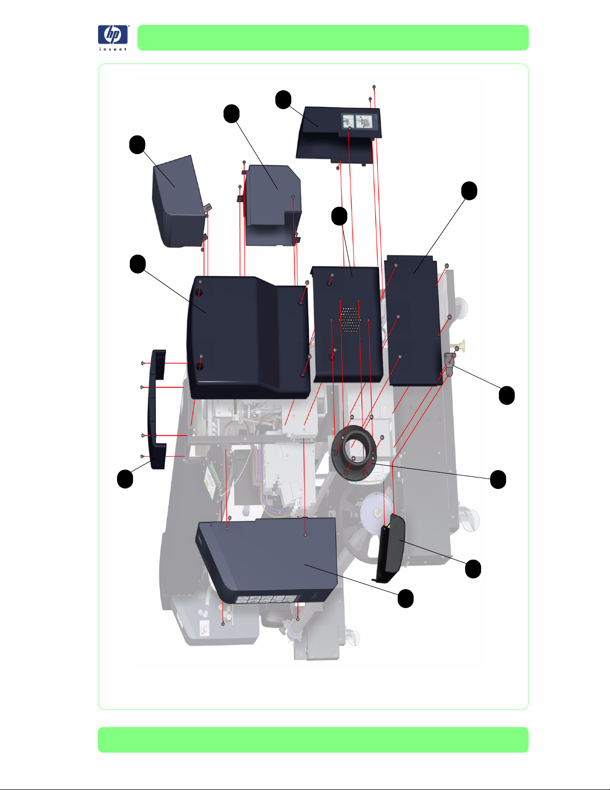
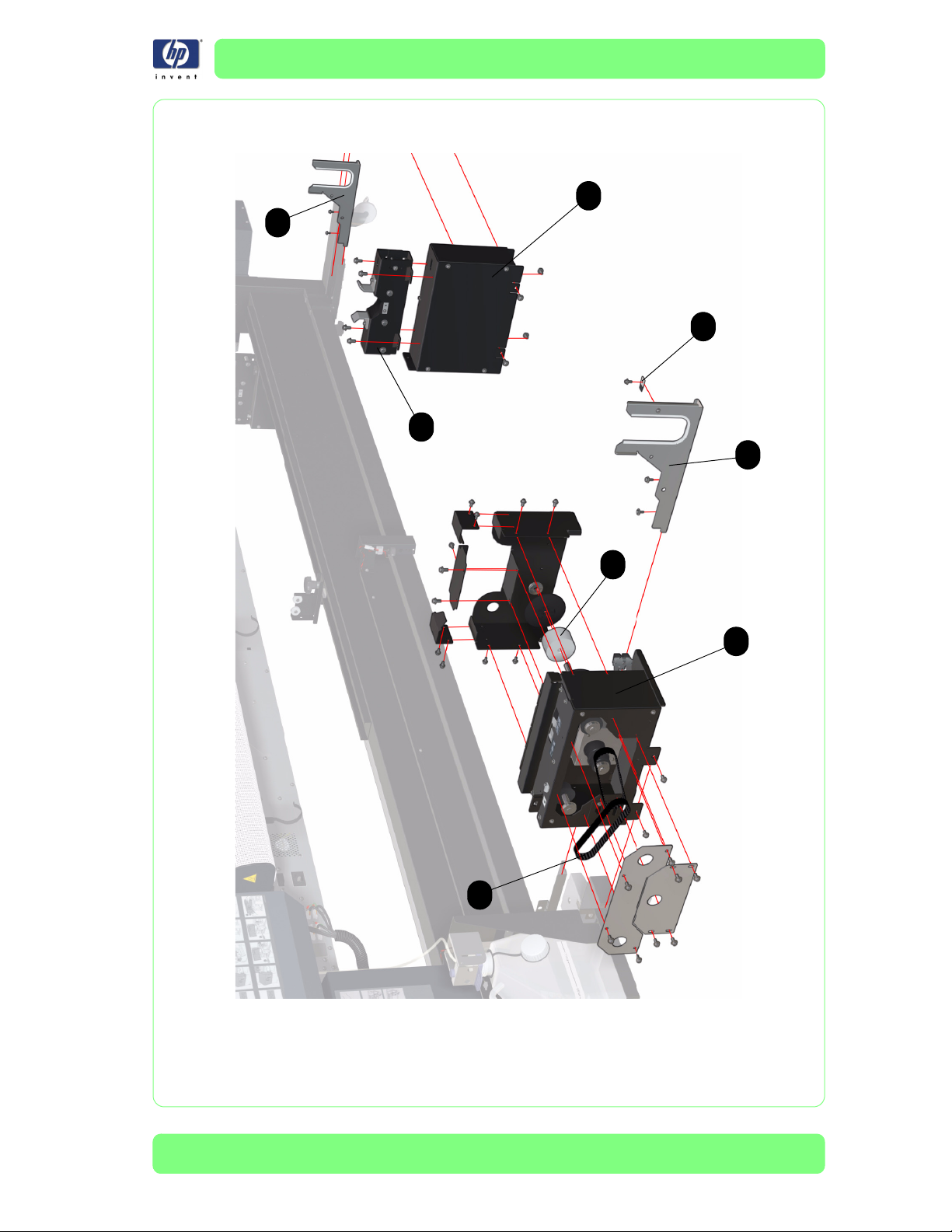
Right Hand Covers
Reference
on
Drawing
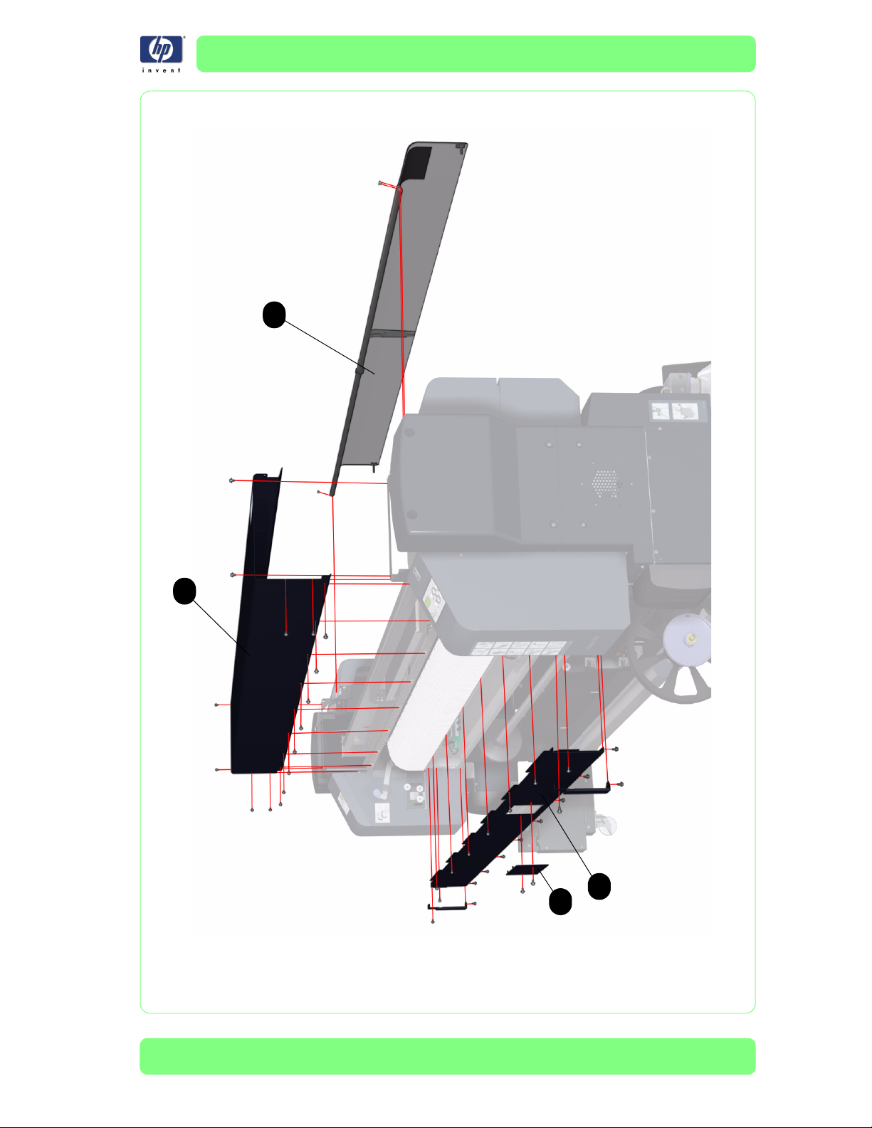
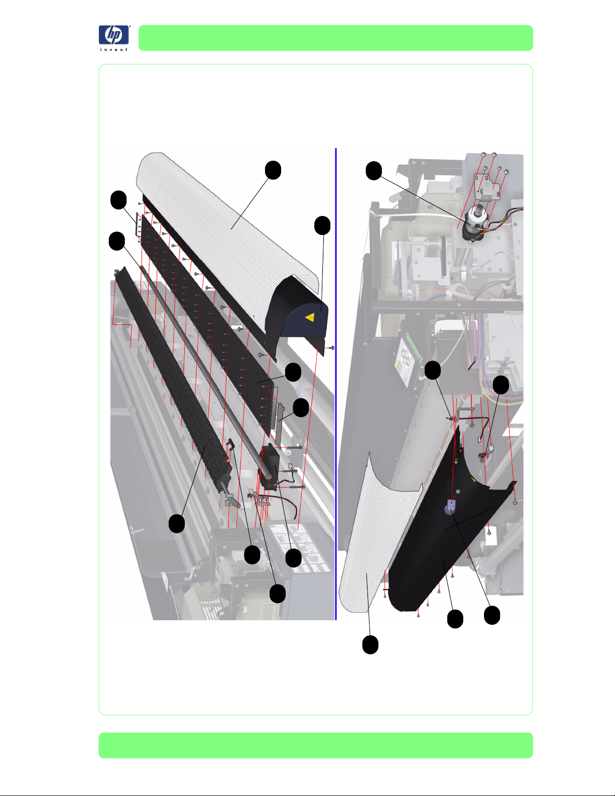
1 Q6665-60011 2 Top Side Cover
2 Q6693-60003 2 Upper Side Cover
3 Q6665-60008 2
4 Q6665-60005 1 Capping Door
5 Q6665-60006 1 Lower Capping Cover
6 Q6693-60004 1 Right Subtank Cover
7 Q6665-60014 1
8 Q6665-60016 4 Side Ink Cartridge Cover
9Q6693-600071Right Rear Ink Cartridge Cover
10 Q6665-60091 1 Plastic Exhaust Attachment
HP Part Number Quantity Description/Comments
Lower Side Cover (includes both the left
(wiping) and right (capping) Lower Side
Cover)
Right Ink Cartridge Door (contains the
hinges)
7-2
HP Designjet 10000s Series Printer Service Manual
Page 3
Parts and Diagrams
9
5
4
8
3
2
7
1
10
7
6
Figure 1: Right Hand Covers
HP Designjet 10000s Series Printer Service Manual
7-3
Page 4
Parts and Diagrams
Left Hand Covers
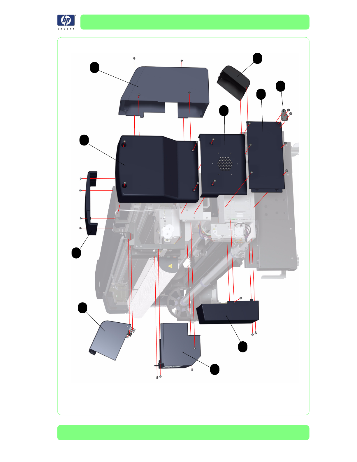
Left Hand Covers
Reference
on
Drawing
1 Q6665-60011 2 Top Side Cover
2 Q6665-60007 2 Upper Side Cover
3 Q6665-60008 2
4 Q6693-60001 1 Wiping Door
5 Q6665-60003 1 Lower Wiping Cover
6 Q6693-60005 1 Left Subtank Cover
7 Q6665-60015 1 Left Ink Cartridge Door (contains the hinges)
8 Q6665-60016 4 Side Ink Cartridge Cover
9 Q6665-60081 1 Left Rear Ink Cartridge Cover
HP Part Number Quantity Description/Comments
Lower Side Cover (includes both the left
(wiping) and right (capping) Lower Side
Cover
7-4
HP Designjet 10000s Series Printer Service Manual
Page 5
Parts and Diagrams
7
6
7
8
3
2
1
4
9
5
Figure 2: Left Hand Covers
HP Designjet 10000s Series Printer Service Manual
7-5
Page 6
Parts and Diagrams
Center Covers
Center Covers
Reference
on
Drawing
1 Q6693-60006 1 Rear Cover ***
2Q6693-600021Top Cover ***
3 Q6693-60011 1 Electronics Module Cover ***
4 Q6665-60021 1 Firmware Access Cover
HP Part Number Quantity Description/Comments
*** These parts are contained in boxes that measure at least 3 meters, so
should be dispatched directly from the parts stock to the customer.
7-6
HP Designjet 10000s Series Printer Service Manual
Page 7
Parts and Diagrams
1
2
3
4
Figure 3: Center Covers
HP Designjet 10000s Series Printer Service Manual
7-7
Page 8
Parts and Diagrams
Electronics Module
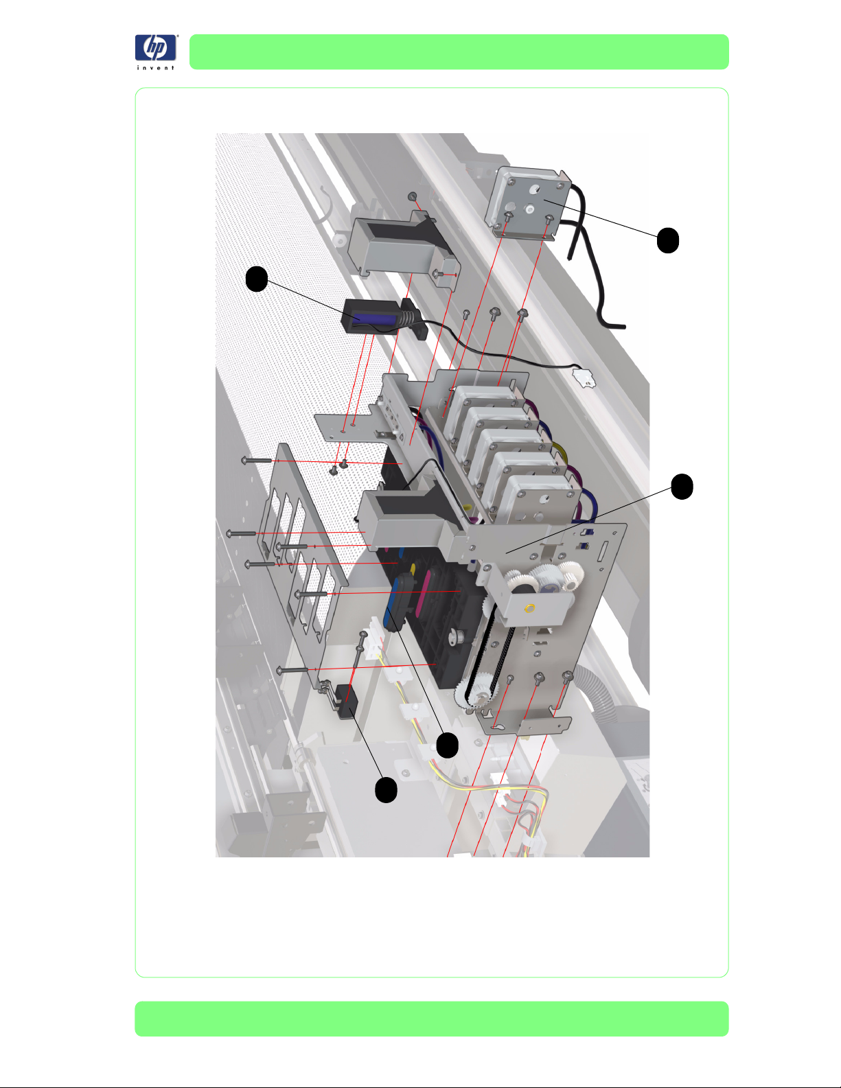
Electronics Module
Reference
on
Drawing
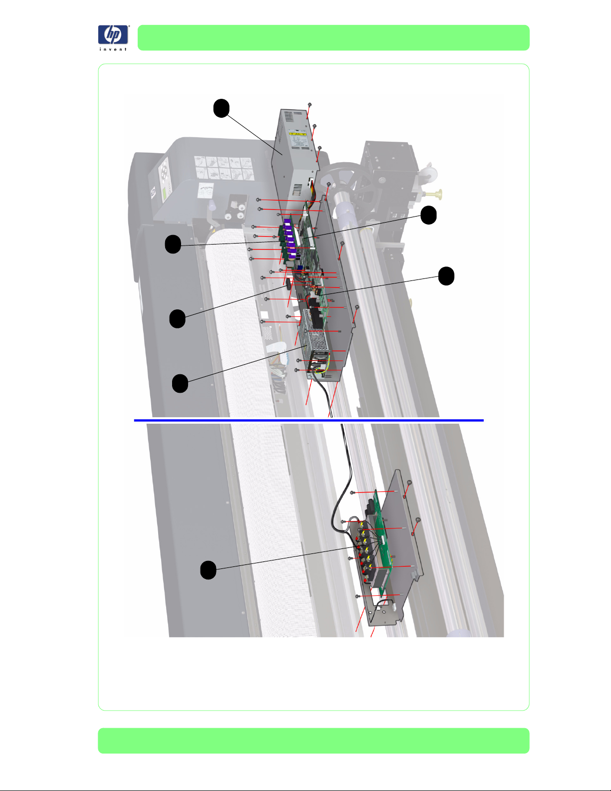
1 Q6693-60010 1 Power Supply Unit
2 Q6665-60017 1 NVRAM
3Q6693-600081
4 Q6665-60019 1 Head Relay Board
5 Q6693-60009 1
6 Q6693-60031 1 Add-on (HEB2) Control PCA
7 Q6693-60032 1 Switching Power Supply
HP Part Number Quantity Description/Comments
Main PCA (includes NVRAM, part #
Q6665-60017)
Heater Relay Assembly (includes the metal
support tray and the AC2 Power Connector)
7-8
HP Designjet 10000s Series Printer Service Manual
Page 9
Parts and Diagrams
1
3
4
6
2
7
5
Figure 4: Electronics Module
HP Designjet 10000s Series Printer Service Manual
7-9
Page 10

Parts and Diagrams
Control Panels
Control Panels
Reference
on
Drawing
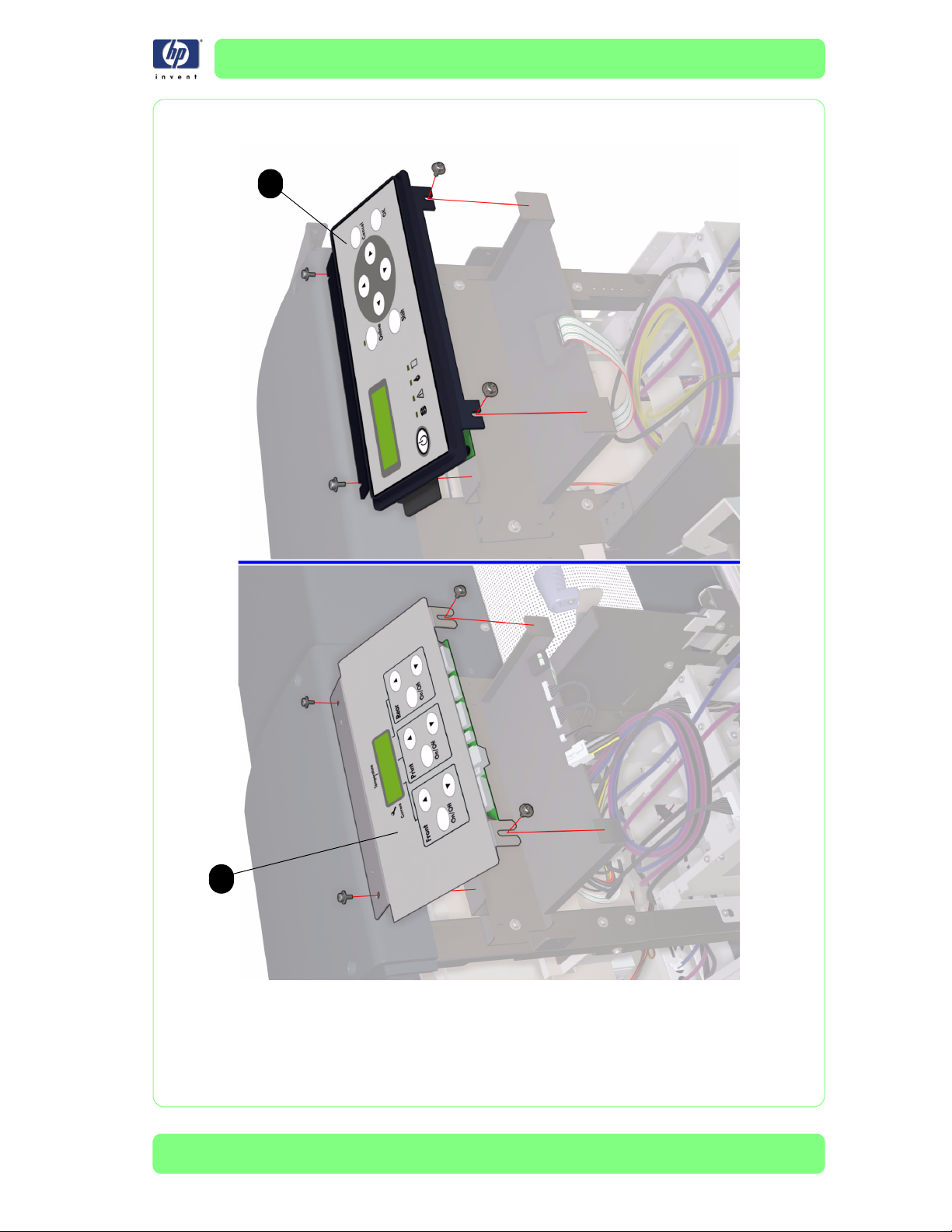
1Q6665-600271Front Panel
2 Q6665-60025 1 Heater Panel
HP Part Number Quantity Description/Comments
7-10
HP Designjet 10000s Series Printer Service Manual
Page 11
Parts and Diagrams
1
2
Figure 5: Control Panels
HP Designjet 10000s Series Printer Service Manual
7-11
Page 12
Parts and Diagrams
Carriage Assembly
Carriage Assembly
Reference
on
Drawing
1 Q6665-60052 2 Printhead Cooling Fan (includes two fans)
2 Q6665-60048 1 Carriage PCA
3 Q6665-60001 6
4 Q6665-60047 6
5 Q6665-60049 1 Encoder Sensor
6 Q6665-60050 1 Line Sensor
7Q6693-600216
8 Q6693-60018 1 Encoder Strip
9Q6665-600261
10 Q6693-60039 1 Discharge Brush
HP Part Number Quantity Description/Comments
Printhead (does not include the Printhead
Connector Assembly)
Printhead Connector Assembly (comes in a
kit of 3 Cables - one for the left hand
Printhead, one for the Center Printhead and
one for the right hand Printhead).
Air Damper Kit (includes six Air Dampers,
tubes going to the Printheads and 1 tie
wrap to secure the Light Cyan tube)
Carriage Home Position Sensor (this Sensor
is also the same as the Media Lever Sensor)
7-12
HP Designjet 10000s Series Printer Service Manual
Page 13
Parts and Diagrams
3
4
1
10
6
5
8
2
7
9
Figure 6: Carriage Assembly
HP Designjet 10000s Series Printer Service Manual
7-13
Page 14

Parts and Diagrams
Scan-Axis Assemblies
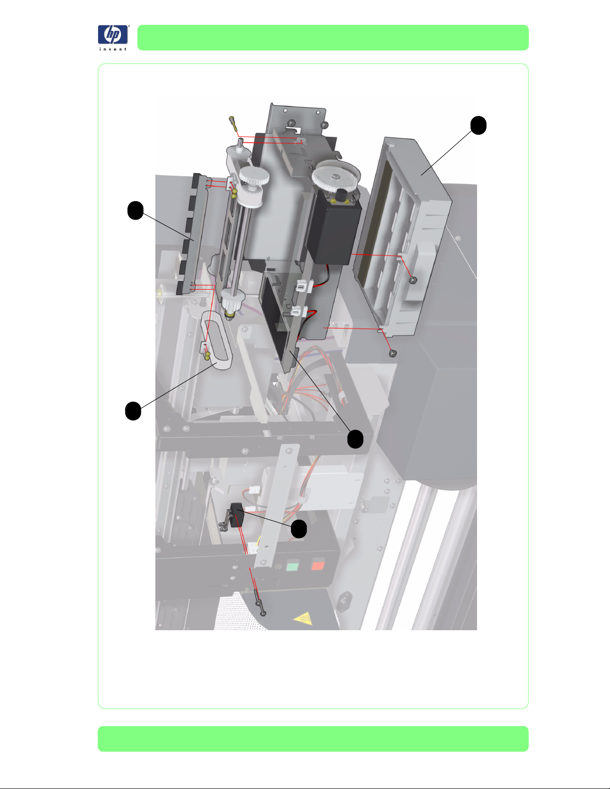
Scan-Axis Assemblies
Reference
on
Drawing
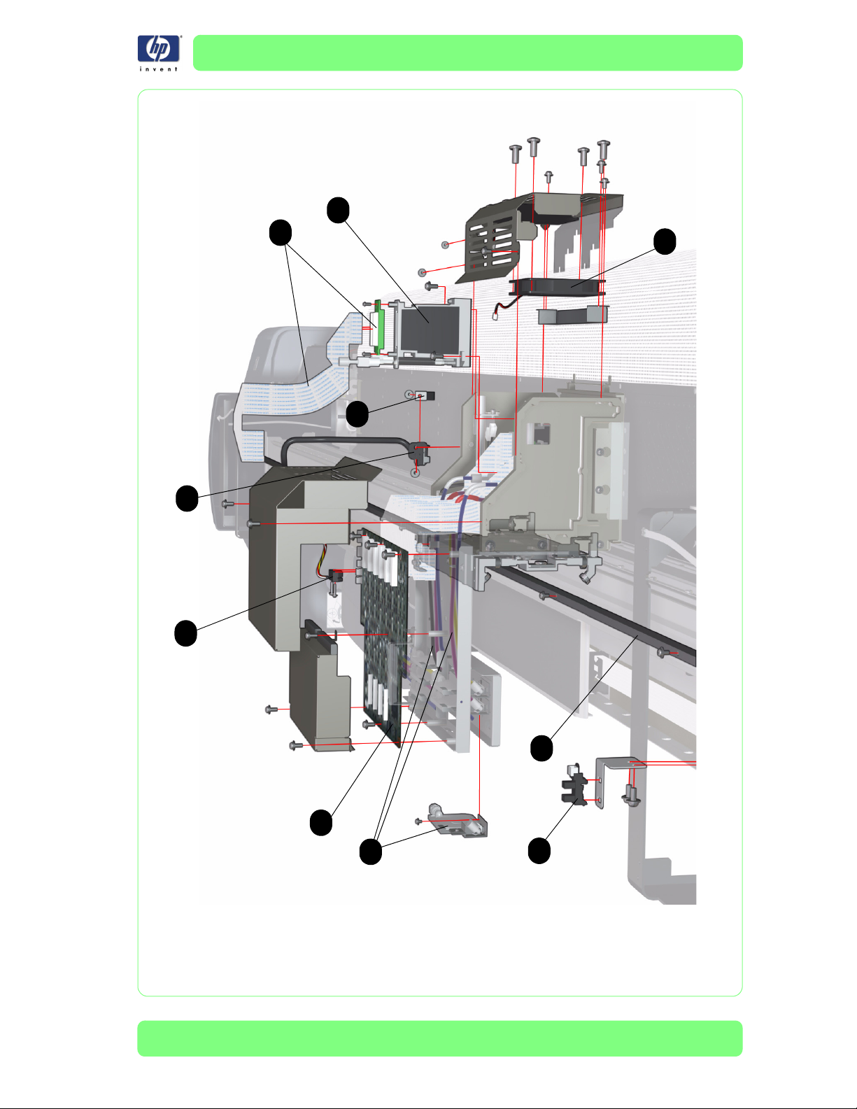
1 Q6693-60020 1
2 Q6693-60019 1 Belt
3 Q6665-60045 1 Tension Pulley
4 Q6665-60043 1 Drive Pulley (includes the Black Rubber Belt)
5 Q6665-60044 1 Scan-Axis Motor Assembly
6Q6665-600921Media-Axis Motor Belt
HP Part Number Quantity Description/Comments
Trailing Cable Assembly (includes four prefolded cables)
7-14
HP Designjet 10000s Series Printer Service Manual
Page 15
Parts and Diagrams
3
1
5
2
4
6
Figure 7: Scan-Axis Assemblies
HP Designjet 10000s Series Printer Service Manual
7-15
Page 16

Parts and Diagrams
Paper Path Assemblies
Paper Path Assemblies
Reference
on
Drawing
1 Q6693-60013 1 Front Heater ***
2 Q6693-60012 1 Center Platen ** ***
3 Q6693-60014 1 Rear Heater ***
4Q6665-600305Vacuum Fan
5 Q6693-60016 1
6 Q6665-60028 2
7 Q6693-60017 40 Pinch Roller Kit
8 Q6693-60060 40 Pinch Roller Blade
9 Q6665-60033 2 Media Sensor (Front and Rear)
10 Q6665-60026 1
11 Q6693-60015 1 Front and Rear Net Kit
12 Q6665-60034 2 Lever Knob
13 Q6693-60038 1 Media Drive Roller ** ***
HP Part Number Quantity Description/Comments
Paper-Axis Motor (includes Belt, Gear,
Spring, Washer and Bearing)
Media Edge Guard (includes eight screws
and four small Guides)
Media Lever Sensor (this Sensor is also the
same as the Carriage Home Position Sensor)
** When ordering the Center Platen or the Media Drive Roller, you MUST
also order the Platen Flatness Adjustment Tools (Part Number Q6693-
60037). Also, due to the size and weight of the Center Platen and the
Media Drive Roller, two Customer Engineers are required when installing
these parts.
*** These parts are contained in boxes that measure at least 3 meters, so
should be dispatched directly from the parts stock to the customer.
7-16
HP Designjet 10000s Series Printer Service Manual
Page 17
Parts and Diagrams
6
13
11
5
3
2
9
10
6
7
8
4
9
Figure 8: Paper Path Assemblies
HP Designjet 10000s Series Printer Service Manual
11
1
12
7-17
Page 18
Parts and Diagrams
Media Entry Assemblies
Media Entry Assemblies
Reference
on
Drawing
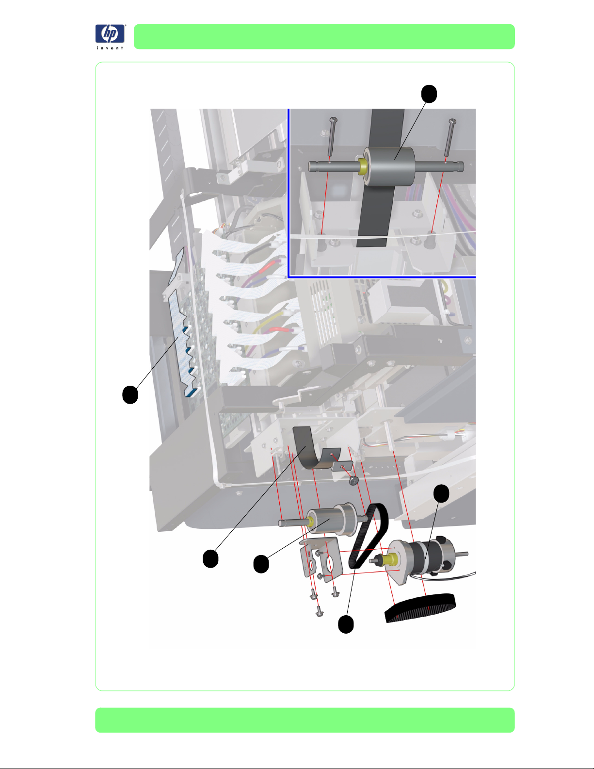
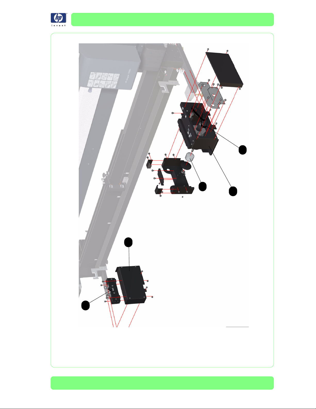
1 Q6693-60028 1 Feeder Drive Unit Assembly
2 Q6693-60029 1 Left Bottom Leg Covers (Front and Rear)
3 Q6693-60030 2 Media Scroller Support
4 Q6693-60034 2
5 Q6693-60059 2
HP Part Number Quantity Description/Comments
Roller (for Feed/TUR Unit) (includes a robust
Allen Key)
Timing Belt (for Feed/TUR Unit) (includes
two belts per support part)
7-18
HP Designjet 10000s Series Printer Service Manual
Page 19
Parts and Diagrams
5
4
1
2
3
Figure 9: Media Entry Assemblies
HP Designjet 10000s Series Printer Service Manual
7-19
Page 20
Parts and Diagrams
Take-Up-Reel Assemblies
Take-Up-Reel Assemblies
Reference
on
Drawing
1 Q6693-60027 1 Take-Up-Reel Drive Unit Assembly
2 Q6693-60029 1 Left Bottom Leg Covers (Front and Rear)
3 Q6693-60030 2 Media Scroller Support
4 Q6693-60034 2
5 Q6693-60059 2
6 Q6693-60050 1 Right Tension Bar Guide
7 Q6693-60051 1 Left Tension Bar Guide
8 Q6693-60039 1 Discharge Brush
HP Part Number Quantity Description/Comments
Roller (for Feed/TUR Unit) (includes a robust
Allen Key)
Timing Belt (for Feed/TUR Unit) (includes
two belts) per support part)
7-20
HP Designjet 10000s Series Printer Service Manual
Page 21
Parts and Diagrams
2
7
8
3
6
4
1
5
Figure 10: Take-Up-Reel Assemblies
HP Designjet 10000s Series Printer Service Manual
7-21
Page 22
Parts and Diagrams
Capping Assemblies
Capping Assemblies
Reference
on
Drawing
1 Q6693-60022 1 Capping Station Assembly
2 Q6665-60061 6 Capping Unit (includes 6 units)
3 Q6665-60062 2 Solenoid Assembly
4 Q6665-60063 6 Prime Assembly
5 Q6665-60024 2 Rear Cover Sensor (includes 2 sensors)
HP Part Number Quantity Description/Comments
7-22
HP Designjet 10000s Series Printer Service Manual
Page 23
Parts and Diagrams
4
3
1
2
5
Figure 11: Capping Assemblies
HP Designjet 10000s Series Printer Service Manual
7-23
Page 24

Parts and Diagrams
Wiping Assemblies
Wiping Assemblies
Reference
on
Drawing
1 Q6665-60064 1 Wiping Station Assembly
2 Q6665-60066 1 Wiper Blade
3 Q6665-60067 1 Wiper Belt (includes 2 belts)
4 Q6665-60065 1 Wiper Cleaning Assembly
5 Q6665-60024 1 Rear Cover Sensor (includes 2 sensors)
HP Part Number Quantity Description/Comments
7-24
HP Designjet 10000s Series Printer Service Manual
Page 25
Parts and Diagrams
4
2
3
1
5
Figure 12: Wiping Assemblies
HP Designjet 10000s Series Printer Service Manual
7-25
Page 26
Parts and Diagrams
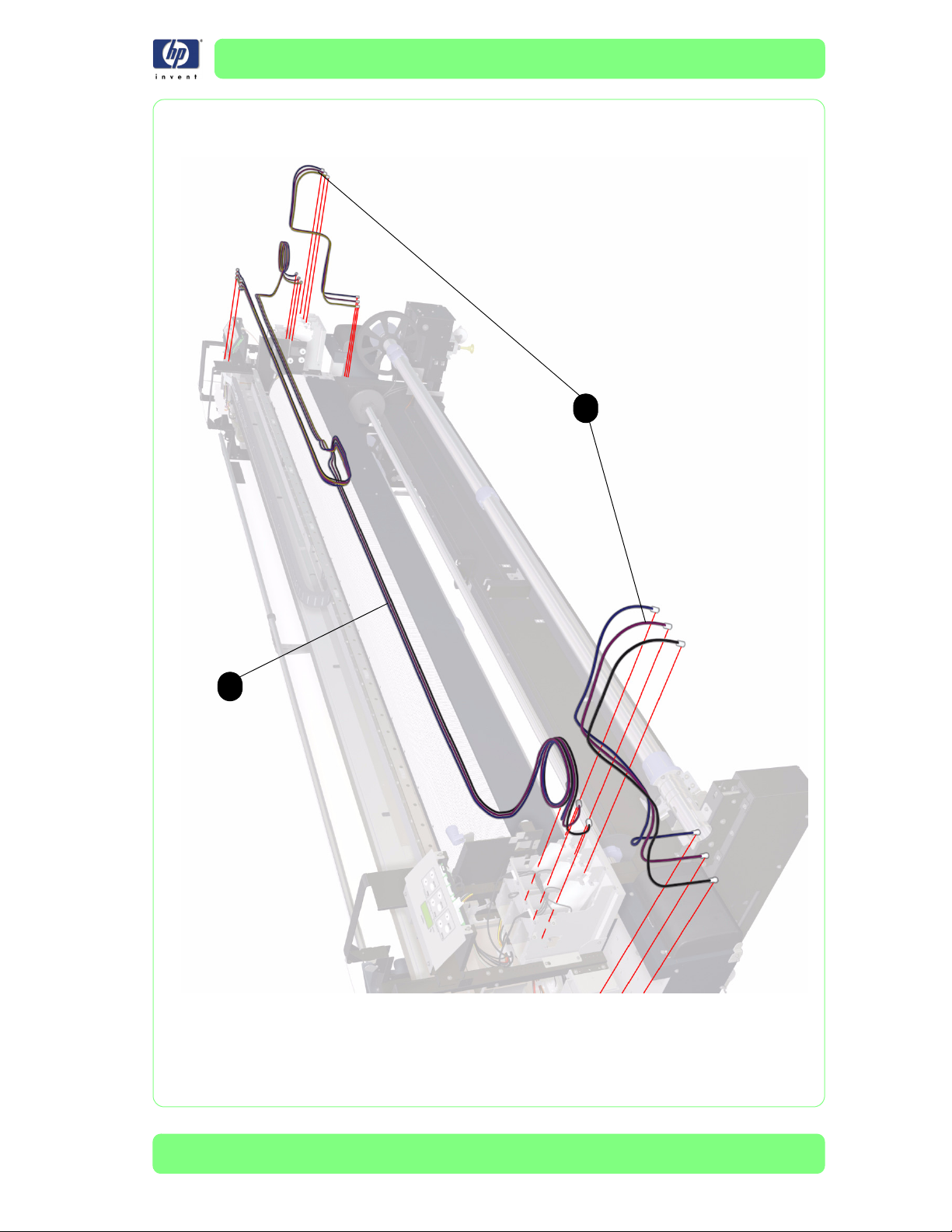
Ink Supply and Subtank Tubes
Ink Supply and Subtank Tubes
Reference
on
Drawing
1 Q6693-60068 1 (set of 6) Tubes Kit 10000
2 Q6665-60086 1 (set of 6) Pump to Subtank Tubes
HP Part Number Quantity Description/Comments
7-26
HP Designjet 10000s Series Printer Service Manual
Page 27
Parts and Diagrams
2
1
HP Designjet 10000s Series Printer Service Manual
7-27
Page 28
Parts and Diagrams
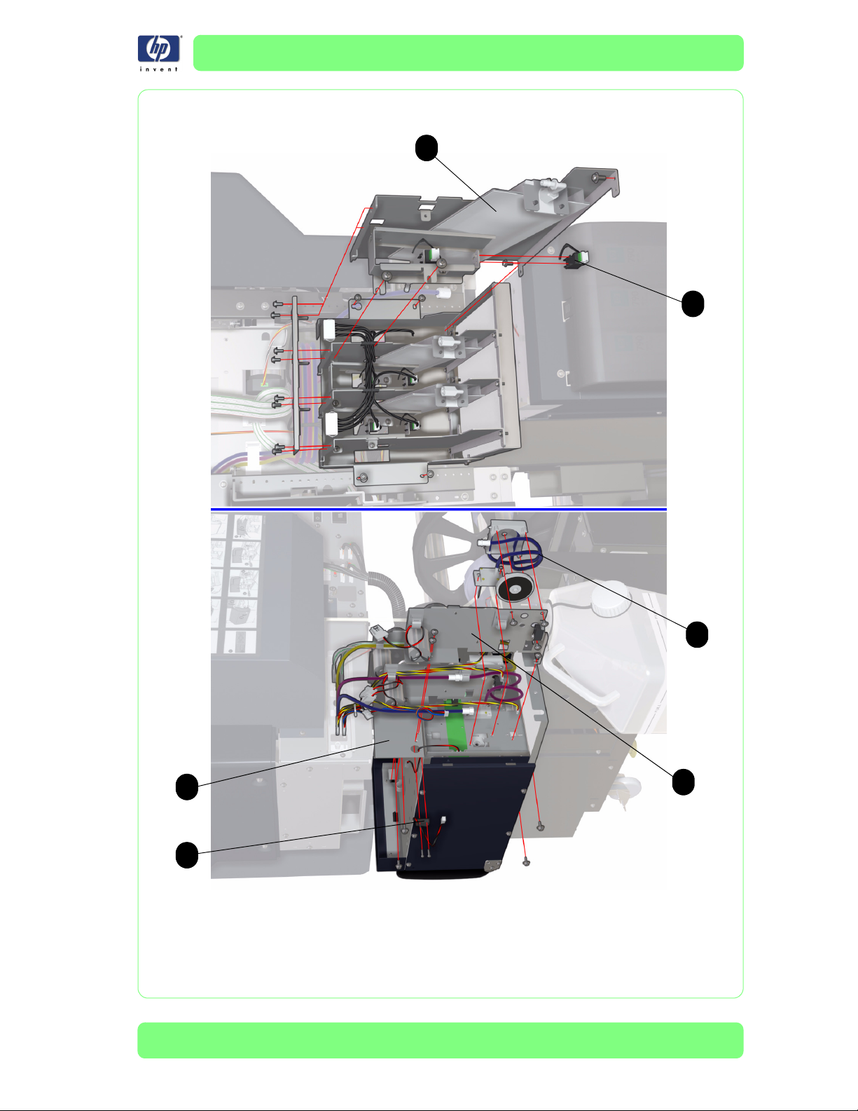
Ink Supply and Subtank Assemblies
Ink Supply and Subtank Assemblies
Reference
on
Drawing
1 Q6665-60055 1 Right Ink Supply Station
- Q6665-60056 1 Left Ink Supply Station
2Q6665-600536
3 Q6665-60054 6 Ink Pump Tube
4 Q6665-60057 2 Ink Cartridge Door Sensor
5 Q6665-60059 2 Subtank Assembly (includes 3 assemblies)
6 Q6665-60058 2 Subtank Sensors (includes 3 sensors)
HP Part Number Quantity Description/Comments
Ink Pump Assembly (includes Ink Pump Tube
and needle)
7-28
HP Designjet 10000s Series Printer Service Manual
Page 29
Parts and Diagrams
5
6
3
1
2
4
Figure 13: Ink Supply and Subtank Assemblies
HP Designjet 10000s Series Printer Service Manual
7-29
Page 30

Parts and Diagrams
Printer Stand and Waste Bottle
Printer Stand and Waste Bottle
Reference
on
Drawing
1 Q6693-60023 2 Foot Casters (includes 2 Foot casters)
2Q6665-600681Waste Bottle
3 Q6665-60057 1 Waste Bottle Sensor
4 Q6693-60025 1 Waste Bottle Holder Assembly and Sensor
5 Q6693-60035 2 Leveler
HP Part Number Quantity Description/Comments
7-30
HP Designjet 10000s Series Printer Service Manual
Page 31

Parts and Diagrams
4
1
3
5
Figure 14: Printer Stand and Waste Bottle
HP Designjet 10000s Series Printer Service Manual
7-31
Page 32

Parts and Diagrams
Media Feed and TUR Sensors
Media Feed and TUR Sensors
Reference
on
Drawing
1Q6693-600331
HP Part Number Quantity Description/Comments
Media Sensor Kit (Includes 2 Receiving
Units and 2 Emitting Units)
7-32
HP Designjet 10000s Series Printer Service Manual
Page 33

Parts and Diagrams
1
1
1
1
Figure 15: Media Feed and TUR Sensors
HP Designjet 10000s Series Printer Service Manual
7-33
Page 34

Parts and Diagrams
Accessories
Accessories
Reference
on
Drawing
1Q6693-600472
2Q6693-600481
3Q6693-600491
4 Q6693-60054 2 Foot Switch
5 Q6693-60057 1
6 Q6693-60055 4 Flange Spacer
7 Q6693-60056 4 Flange Stopper
8 Q6693-60041 2 Subscroller Flange
9 Q6693-60050 1 Right Tension Bar Guide
10 Q6693-60051 1 Left Tension Bar Guide
11 Q6693-60062 2 Tension Bar Flange
12 Q6693-60063 1 Media Roll Spacer (includes two screws)
HP Part Number Quantity Description/Comments
Main Scroller *** (for the Media feed side
or for the Take-up-reel side)
Sub Scroller *** (includes the Sub-Scroller
Assembly)
Tension Bar Kit (can be used to replace any
of the three tension bars and includes the
black flanges and yellow flanges which can
be used on the Media feed side and Takeup-reel side)
Sub Scroller Holder Assembly (includes the
Tension Arm Assembly)
7-34
- Q6693-60064 1 Tension Bar Holder
- Q6693-60040 1 Edge Guard Kit (when using a Liner)
-Q6693-600421
- Q6693-60046 1 Liner Separator Bar Set ***
- Q6693-60052 1
- Q6693-60053 1 Paper Set Gauge
- Q6693-60058 1 Flange Joint
- C7790-60425 1 USB Cable (5 m)
*** These parts are contained in boxes that measure at least 3 meters, so
should be dispatched directly from the parts stock to the customer.
HP Designjet 10000s Series Printer Service Manual
Edge Guard Kit for Dual-Roll Printing
(includes eight crews and four small guides)
Paper Tube Flanges Kit (Includes two big
black Media Tubes Flanges, one rubber
spacer A, one rubber spacer B and one
rubber spacer C)
Page 35

Parts and Diagrams
5
2
4
9
11
8
1
12
6
3
7
10
Figure 16: Accessories
HP Designjet 10000s Series Printer Service Manual
7-35
Page 36

Parts and Diagrams
Service Tools
Service Tools
Reference
on
Drawing
1 Q6693-60024 1 Carriage Height Adjustment Tools
2 Q6665-60071 1 Printhead Position Adjustment Tools
3 Q6665-60075 1 Capping Height Adjustment Tools
4 Q6693-60037 1
HP Part Number Quantity Description/Comments
Platen Flatness Adjustment Tools (includes
Shims and Dummy Heater Sensor).
Shims included are:
30 small Shims 0.1 mm (100 µm).
30 small Shims 0.2 mm (200 µm).
15 large Shims 0.1 mm (100 µm).
15 large Shims 0.2 mm (200 µm).
If any of the above tools are required, please contact the HP Response
Center or the nearest HP Support Office.
7-36
HP Designjet 10000s Series Printer Service Manual
Page 37

Parts and Diagrams
2
3
1
4
Figure 17: Service Tools
HP Designjet 10000s Series Printer Service Manual
7-37
Page 38

Parts and Diagrams
Air Purifier System
Service Tools
Reference
on
Drawing
1 Q6668-60007 1 Turbine Assembly 110V
2 Q6668-60008 1 Turbine Assembly 220V
3 Q6668-60009 1 APS Electronic Module / Front Panel
4 Q6668-60010 1 Foot Casters
5 Q6668-60012 1
6 Q6668-60017 1
7 Q6679-60001 1 APS Replacement Filter
HP Part Number Quantity Description/Comments
APS Tubes Kit (with tubes of 4 meters for HP
Designjet 8000s and 9000s)
APS Tubes Kit (with tubes of 6 meters for HP
Designjet 8000s, 9000s and 10000s)
7-38
HP Designjet 10000s Series Printer Service Manual
Page 39

Removal and Installation 8
Introduction 8-2
Covers 8-3
Front Panel 8-25
Heater Panel 8-27
Front Heater 8-29
Rear Heater 8-32
Center Platen 8-34
Vacuum Fan 8-35
Main PCA 8-36
NVRAM 8-41
Head Relay Board 8-42
Add-On (HEB2) Control PCA 8-45
Switching Power Supply Unit 8-47
Power Supply Unit 8-50
Heater Relay Assembly 8-52
Waste Bottle Sensor 8-54
Front Media Sensor 8-56
Rear Media Sensor 8-58
Media Lever Sensor 8-59
Rear Cover Sensor 8-61
Home Position Sensor 8-66
Paper-Axis Motor and Belt 8-68
Scan-Axis Motor and Belt 8-72
Carriage Drive Assembly (Includes Carriage Belt) 8-75
Encoder Strip 8-79
Trailing Cable 8-80
Printhead Cooling Fans 8-88
Printhead 8-92
Printhead Connector Assembly 8-95
Carriage PCA 8-97
Carriage Base Plate Replacement 8-101
Air Damper 8-112
Encoder Sensor 8-116
Line Sensor 8-118
Ink Pump Assembly 8-120
Ink Supply Station (Left or Right) 8-122
Ink-supply and Subtank Tubes 8-125
Subtank Sensors 8-151
Capping Station Assembly 8-156
Capping Unit 8-165
Prime Assembly 8-166
Solenoid Assembly 8-170
Waste Bottle Holder and Sensor Assembly 8-175
Wiping Station Assembly 8-181
Wiper Cleaning Assembly 8-185
Wiper Blade 8-186
Wiper Belts 8-188
Pinchwheel Assembly 8-192
Drive Roller 8-196
Media Feed Drive Unit Assembly 8-201
Take-Up-Reel Drive Unit Assembly 8-205
Drive Unit Rollers 8-210
Drive Unit Timing Belt 8-216
Media Sensors (Media End, Media Slack and Take-Up-Reel) 8-220
White Nets (For Front and Rear Heaters) 8-226
Sub-Scroller Flange 8-229
8
HP Designjet 10000s Series Printer Service Manual
8-1
Page 40

Removal and Installation
Introduction
This chapter is a step by step guide to the removal and installation of the key components in the
printer. You may find it useful to tick off the steps as they are performed. Use the illustration at
each procedure to identify the parts referred to in the text.
The procedures appear in order of removal. So the whole machine can be stripped down by
starting at the beginning of this chapter and working through the subsequent procedures.
Before using this chapter to remove and install a new component, always
make sure that you have performed the relevant service test from Chapter 4. If
the test passes you will not need to replace the component.
Safety Precautions
Review WARNING and CAUTION symbols and instructions before you service the printer.
Follow these warnings and cautions for your protection and to avoid damaging the printer.
Serious shock hazard leading to death or injury may result if you do not take
the following precautions:
Ensure that the ac power outlet (mains) has a protective earth (ground)
terminal.
Switch the Printer Off, and disconnect it from the power source prior to
performing any maintenance.
Prevent water or other liquids from running onto electrical components or
circuits, or through openings in the module.
Electrostatic Discharge (ESD) Precautions
To prevent damage to the Printer circuits from high-voltage electrostatic discharge (ESD):
1. Do not wear clothing that is subject to static build-up.
2. Do not handle integrated circuits (ICs) in carpeted areas.
3. Do not remove an IC or a printed circuit assembly (PCA) from its conductive foam pad or
conductive packaging until you are ready to install it.
4. Ground (earth) your body while disassembling and working on the Printer.
5. After removing a cover from the Printer, attach an earthing (ground) lead between the PCA
common and earth ground. Touch all tools to earth ground to remove static charges before
using them on the Printer.
6. After removing any PCA from the Printer, place it on a conductive foam pad or into its
conductive packaging to prevent ESD damage to any ICs on the PCA.
8-2
HP Designjet 10000s Series Printer Service Manual
Page 41

Rear Cover
Removal
Switch off the product and remove the power cable.
1. Remove two screws that secure the Rear
Cover to the right hinge.
2. Remove two screws that secure the Rear
Cover to the left hinge.
Removal and Installation
3. Remove the Rear Cover from the Printer.
HP Designjet 10000s Series Printer Service Manual
8-3
Page 42

Removal and Installation
Upper Side Cover (Left or Right)
Removal
Switch off the product and remove the power cable.
1. Remove four screws that secure the Upper
Side Cover to the Printer.
2. Remove the Upper Side Cover from the
Printer.
8-4
HP Designjet 10000s Series Printer Service Manual
Page 43

Top Side Cover (Left or Right)
Removal
Switch off the product and remove the power cable.
1.
Remove the Upper Side Cover (Left or Right)
⇒
Page 8-4.
2. Remove four screws that secure the Top
Side Cover to the Printer.
Removal and Installation
3. Remove the Top Side Cover from the
Printer.
HP Designjet 10000s Series Printer Service Manual
8-5
Page 44

Removal and Installation
Top Cover
Removal
Switch off the product and remove the power cable.
1. Remove the Rear Cover ⇒ Page 8-3.
2. Remove the Upper Side Cover (Left and
Right) ⇒ Page 8-4.
3. Remove the Top Side Cover (left and Right)
⇒ Page 8-5.
In steps 4 and 5, the screws at
the bottom of the Cover are short
screws (M4 x 6) and the screws
at the top and at the sides are
long screws (M4 x 10).
4. Remove seven screws that secure the Top
Cover to the left hand side of the Printer.
8-6
5. Remove nine screws that secure the Top
Cover to the right hand side of the Printer.
HP Designjet 10000s Series Printer Service Manual
Page 45

Removal and Installation
6. Remove the Top Cover from the Printer.
HP Designjet 10000s Series Printer Service Manual
8-7
Page 46

Removal and Installation
Lower Side Cover (Left or Right)
Removal
Switch off the product and remove the power cable.
1. Open the Ink Cartridge Door and remove
two screws that secure the metal cover to
the Ink Supply Station. Remove the metal
cover from the Ink Supply Station.
2. Remove two screws that secure the Lower
Side Cover to the Printer.
8-8
3. Remove the Lower Side Cover from the
Printer.
HP Designjet 10000s Series Printer Service Manual
Page 47

Subtank Cover (Left or Right)
Removal
Switch off the product and remove the power cable.
1. Remove the Upper Side Cover (Left or
Right) ⇒ Page 8-4.
2. Remove the Lower Side Cover (Left or Right)
⇒ Page 8-8.
3. Remove two screws that secure the
Electronics Module Side Trim to the Printer.
Removal and Installation
4. Remove the Electronics Module Side Trim
from the Printer.
5. Remove two screws that secure the Subtank
Cover to the Printer.
HP Designjet 10000s Series Printer Service Manual
8-9
Page 48

Removal and Installation
6. Remove two screws that secure the Subtank
Cover to the Printer.
7. Remove the Subtank Cover from the Printer.
8-10
HP Designjet 10000s Series Printer Service Manual
Page 49

Lower Capping Cover
Removal
Switch off the product and remove the power cable.
1. Remove the Upper Side Cover (Right) ⇒
Page 8-4.
2. Remove the Lower Side Cover (Right) ⇒
Page 8-8.
3. Open the Capping Door.
Removal and Installation
4. Remove three screws that secure the Lower
Capping Cover to the Printer.
HP Designjet 10000s Series Printer Service Manual
8-11
Page 50

Removal and Installation
5. Remove one screw that secures the Lower
Capping Cover to the Printer.
6. Remove the Lower Capping Cover from the
Printer.
8-12
HP Designjet 10000s Series Printer Service Manual
Page 51

Capping Door
Removal
Switch off the product and remove the power cable.
1.
Remove the Upper Side Cover (Right)
Page 8-4.
2. Remove the Lower Side Cover (Right) ⇒
Page 8-8.
3. Open the Window.
Removal and Installation
⇒
4. Open the Capping Door.
5. Remove one screw that secures the
Capping Door hinge to the Printer.
HP Designjet 10000s Series Printer Service Manual
8-13
Page 52

Removal and Installation
6. Remove the Hinge from the Printer.
7. Slide the Capping Door to the left and
remove from the Printer.
8-14
HP Designjet 10000s Series Printer Service Manual
Page 53

Lower Wiping Cover
Removal
Switch off the product and remove the power cable.
1. Remove the Upper Side Cover (Left) ⇒
Page 8-4.
2. Remove the Lower Side Cover (Left) ⇒
Page 8-8.
3. Open the Wiping Door.
Removal and Installation
4. Remove three screws that secure the Lower
Wiping Cover to the Printer.
HP Designjet 10000s Series Printer Service Manual
8-15
Page 54

Removal and Installation
5. Remove one screw that secures the Lower
Wiping Cover to the Printer.
6. Remove the Lower Wiping Cover from the
Printer.
8-16
HP Designjet 10000s Series Printer Service Manual
Page 55

Wiping Door
Removal
Switch off the product and remove the power cable.
1.
Remove the Upper Side Cover (Left)
Page 8-4.
2. Remove the Lower Side Cover (Left) ⇒
Page 8-8.
3. Open the Window.
Removal and Installation
⇒
4. Open the Wiping Door.
5. Remove one screw that secures the Wiping
Door hinge to the Printer.
HP Designjet 10000s Series Printer Service Manual
8-17
Page 56

Removal and Installation
6. Remove the Hinge from the Printer.
7. Slide the Wiping Door to the right and
remove from the Printer.
8-18
HP Designjet 10000s Series Printer Service Manual
Page 57

Ink Cartridge Door (Left or Right)
Removal
Switch off the product and remove the power cable.
1. Remove one screw that secures the Ink
Cartridge Door Hinge to the Printer.
2. Remove the Hinge from the Printer.
Removal and Installation
3. Open the Ink Cartridge Door and remove
from the Printer.
HP Designjet 10000s Series Printer Service Manual
8-19
Page 58

Removal and Installation
Rear Ink Cartridge Cover (Left or Right)
Removal
Switch off the product and remove the power cable.
1. Remove three screws that secure the Rear
Ink Cartridge Cover to the Printer.
2. Loosen one screw that secures the Rear Ink
Cartridge Cover to the Printer.
8-20
3. Remove the Rear Ink Cartridge Cover from
the Printer.
HP Designjet 10000s Series Printer Service Manual
Page 59

Electronics Module Cover
Removal
Switch off the product and remove the power cable.
1. Remove two screws that secure the Left
Electronics Module Side Trim to the Printer.
2. Remove the Left Electronics Module Side
Trim from the Printer.
Removal and Installation
3. Remove two screws that secure the Right
Electronics Module Side Trim to the Printer.
HP Designjet 10000s Series Printer Service Manual
8-21
Page 60

Removal and Installation
4. Remove the Right Electronics Module Side
Trim from the Printer.
5. Remove eight screws that secure the top
and the side of the Electronics Module
Cover to the Printer.
6. Loosen eight screws that secure the bottom
of the Electronics Module Cover to the
Printer.
8-22
HP Designjet 10000s Series Printer Service Manual
Page 61

Removal and Installation
7. Remove the Electronics Module Cover from
the Printer.
HP Designjet 10000s Series Printer Service Manual
8-23
Page 62

Removal and Installation
Firmware Access Cover
Removal
Switch off the product and remove the power cable.
1. Remove two screws that secure the
Firmware Access Cover to the Printer.
2. Remove the Firmware Access Cover from
the Printer.
8-24
HP Designjet 10000s Series Printer Service Manual
Page 63

Front Panel
Removal
Switch off the product and remove the power cable.
1. Remove the Upper Side Cover (Right) ⇒
Page 8-4.
2. Remove the Lower Side Cover (Right) ⇒
Page 8-8.
3. Remove the Subtank Cover (Right) ⇒ Page
8-9.
4. Disconnect the Front Panel Cable from the
Front Panel.
Removal and Installation
5. Loosen two screws that secure the Front
Panel to the Printer.
HP Designjet 10000s Series Printer Service Manual
8-25
Page 64

Removal and Installation
6. Remove two screws that secure the Front
Panel to the Printer.
7. Remove the Front Panel from the Printer.
8-26
HP Designjet 10000s Series Printer Service Manual
Page 65

Heater Panel
Removal
Switch off the product and remove the power cable.
1. Remove the Upper Side Cover (Left) ⇒
Page 8-4.
2. Remove the Lower Side Cover (Left) ⇒
Page 8-8.
3.
Remove the Subtank Cover (Left) ⇒ Page 8-9.
4. Disconnect ALL the Heater Panel Cables
from the Heater Panel.
Removal and Installation
5. Loosen two screws that secure the Heater
Panel to the Printer.
HP Designjet 10000s Series Printer Service Manual
8-27
Page 66

Removal and Installation
6. Remove two screws that secure the Heater
Panel to the Printer.
7. Remove the Heater Panel from the Printer.
8-28
HP Designjet 10000s Series Printer Service Manual
Page 67

Front Heater
Removal
Switch off the product and remove the power cable.
1. Remove the Upper Side Cover (Left) ⇒
Page 8-4.
2. Remove the Lower Side Cover (Left) ⇒
Page 8-8.
3. Remove the Subtank Side Cover (Left) ⇒
Page 8-9.
4. Carefully pull out the Left Subtank Station
slightly ⇒ Page 8-151.
5. Remove three screws that secure the Sub-
Scroller Holder to the Printer.
Removal and Installation
6. Remove the Sub-Scroller Holder from the
Printer.
HP Designjet 10000s Series Printer Service Manual
8-29
Page 68

Removal and Installation
7. Remove one screw from either side of the
Printer.
8. Remove seven screws that secure the
bottom of the Front Heater to the Printer.
9. Pull out the Front Heater slightly.
8-30
HP Designjet 10000s Series Printer Service Manual
Page 69

Removal and Installation
10. Disconnect the Front Heater Cables from
the Front Heater.
11. Remove the Front Heater (including the
white net) from the Printer.
HP Designjet 10000s Series Printer Service Manual
8-31
Page 70

Removal and Installation
Rear Heater
Removal
Switch off the product and remove the power cable.
1. Loosen the screw that secures each Tension
Bar Holder and remove the five Holders
from the Printer.
2. Loosen nine screws that secure the bottom
of the Rear Heater to the Printer.
8-32
3. Remove 11 screws that secure the top of
the Rear Heater to the Printer.
Make sure that the washers do
NOT slip underneath the Center
Platen.
HP Designjet 10000s Series Printer Service Manual
Page 71

Removal and Installation
4. Pull out the Rear Heater slightly.
5. Disconnect the Rear Heater Cables from
the Rear Heater.
6. Remove the Rear Heater (including the
white net) from the Printer.
When re-installing the Rear heater, make sure you push the white net evenly
underneath the Center Platen (start from the center and move outwards).
When ins talling the top 11 sc rews, make sure you tighten them starting from the
center and then moving outwards.
When positioning the Rear Heater, make sure you do NOT trap the captive
washers (on the bottom) between the Rear heater and the Printer.
HP Designjet 10000s Series Printer Service Manual
8-33
Page 72

Removal and Installation
Center Platen
Removal
Switch off the product and remove the power cable.
1. Remove the Rear Heater ⇒ Page 8-32.
2. Disconnect ALL the cables connected to the
Center Platen.
3. Remove 55 screws that secure the Center
Platen to the Printer.
4. Remove the Center Platen from the Printer.
When removing the Center
Platen, take care not to disturb
the Shims that are placed
underneath the Center Platen.
Once the Center Platen has been
installed correctly, you must
perform the Platen Flatness
Adjustment. For further
information, refer to Page
5-45
.
8-34
HP Designjet 10000s Series Printer Service Manual
Page 73

Vacuum Fan
Removal
Switch off the product and remove the power cable.
1. Remove the Rear Heater ⇒ Page 8-32.
2. Disconnect the Vacuum Fan Cable.
Removal and Installation
3. Using a small 5mm Allen Key, remove 3
screws that secure the Vacuum Fan to the
Printer.
4. Remove the Vacuum Fan from the Printer.
HP Designjet 10000s Series Printer Service Manual
8-35
Page 74

Removal and Installation
Main PCA
Removal
Switch off the product and remove the power cable.
1. Remove the Electronics Module Cover ⇒
Page 8-21.
2. Remove five screws that secure the Main
PCA Tray to the Printer from the rear.
3. Remove three screws that secure the Main
PCA Tray to the front of the Printer.
4. Disconnect ALL the cables connected to the
Main PCA.
8-36
HP Designjet 10000s Series Printer Service Manual
Page 75

Removal and Installation
5. Disconnect ALL the cables connected to the
Add-On Control PCA (no need to
disconnect cables connected between the
Add-On Control PCA and the Switching
Power Supply Unit).
6. Remove one screw that secures the
Grounding Strip and disconnect the cable
from the Switching Power Supply Unit.
7. Remove the Main PCA Tray from the
Printer.
HP Designjet 10000s Series Printer Service Manual
8-37
Page 76

Removal and Installation
8. Pull up and remove the NVRAM from the
Main PCA.
9. Remove four screws that secure the Head
Relay Board to the Main PCA.
10. Remove the Head Relay Board from the
Main PCA.
8-38
HP Designjet 10000s Series Printer Service Manual
Page 77

Removal and Installation
11. Remove 10 screws that secure the Main
PCA to the Tray.
12. Remove one screw that secures the USB
Connector to the Tray.
13. Remove the Main PCA from the Tray.
Make sure that you re-install the NVRAM and the Head Relay Board on the NEW Main PCA.
Once the NEW Main PCA is installed, power ON the Printer and do the following:
1. Enter into the Maintenance Mode ⇒ Page 4-7.
2. Press
the
Shift
key once and then
the W key to enter in to the Setup menu.
HP Designjet 10000s Series Printer Service Manual
8-39
Page 78

Removal and Installation
3. In the Setup submenu, scroll to "Save Calibs" and press the OK key.
# SAVE CALIBS
>
4.
You will need to confirm that you want to save the NVRAM Calibrations by pressing the OK key.
# SAVE CALIBS
OK?
*
5. In the Setup submenu, scroll to "Save NVRAM" and press the OK key.
# SAVE NVRAM
>
6. You will need to confirm that you want to save the NVRAM contents by pressing the OK key.
# SAVE NVRAM
OK?
*
If both the NVRAM and the Main PCA are replaced at the same time, please refer to Chapter 1 for further information.
8-40
HP Designjet 10000s Series Printer Service Manual
Page 79

NVRAM
Removal
Switch off the product and remove the power cable.
1. Remove the Electronics Module Cover ⇒
Page 8-21.
2. Carefully pull up and remove the NVRAM
from the Main PCA.
Removal and Installation
Once the NEW NVRAM is installed, power ON the Printer and do the following:
1. Enter into the Maintenance Mode ⇒ Page 4-7.
2. Press
3.
4.
5. In the Setup submenu, scroll to "
the
Shift
key once and then
the W key to enter in to the Setup menu.
In the Setup submenu, scroll to "NVRAM Init" and press th
# NVRAM INIT
>
You will need to confirm
# NVRAM INIT
OK?
*
# RESTORE NVRAM
>
that you want to initialize the NVRAM by pressing the OK key
Restore NVRAM
" and press the OK key.
e OK
key.
.
6. You will need to confirm that you want to restore the NVRAM contents by pressing the OK key.
# RESTORE NVRAM
OK?
*
7. Power Off the Printer, wait a few seconds and then power the Printer On again.
If both the NVRAM and the Main PCA are replaced at the same time, please
refer to Chapter 1 for further information.
HP Designjet 10000s Series Printer Service Manual
8-41
Page 80

Removal and Installation
Head Relay Board
Removal
Switch off the product and remove the power cable.
1. Remove the Electronics Module Cover ⇒
Page 8-21.
2. Remove five screws that secure the Main
PCA Tray to the Printer from the rear.
3. Remove three screws that secure the Main
PCA Tray to the front of the Printer.
4. Disconnect ALL the cables connected to the
Main PCA.
8-42
HP Designjet 10000s Series Printer Service Manual
Page 81

Removal and Installation
5. Disconnect ALL the cables connected to the
Add-On Control PCA (no need to
disconnect cables connected between the
Add-On Control PCA and the Switching
Power Supply Unit).
6. Remove one screw that secures the
Grounding Strip and disconnect the cable
from the Switching Power Supply Unit.
7. Remove the Main PCA Tray from the
Printer.
HP Designjet 10000s Series Printer Service Manual
8-43
Page 82

Removal and Installation
8. Remove four screws that secure the Head
Relay Board to the Main PCA.
9. Remove the Head Relay Board from the
Main PCA.
8-44
HP Designjet 10000s Series Printer Service Manual
Page 83

Add-On (HEB2) Control PCA
Removal
Switch off the product and remove the power cable.
1. Remove the Electronics Module Cover ⇒
Page 8-21.
2. Remove five screws that secure the Main
PCA Tray to the Printer from the rear.
Removal and Installation
3. Remove three screws that secure the Main
PCA Tray to the front of the Printer.
4. Disconnect ALL the cables connected to the
Add-On Control PCA.
HP Designjet 10000s Series Printer Service Manual
8-45
Page 84

Removal and Installation
5.
Pull out slightly the Main PCA Tray from the
Printer and remove five screws that secure the
Add-On Control PCA to the Main PCA Tray.
If you cannot access the screws
that secure the Add-On Control
PCA, then it is recommended to
disconnect ALL the cables from
the Main PCA and remove the
Main PCA Tray from the Printer.
6. Remove the Add-On Control PCA from the
Main PCA Tray.
8-46
HP Designjet 10000s Series Printer Service Manual
Page 85

Switching Power Supply Unit
Removal
Switch off the product and remove the power cable.
1. Remove the Electronics Module Cover ⇒
Page 8-21.
2. Remove five screws that secure the Main
PCA Tray to the Printer from the rear.
Removal and Installation
3. Remove three screws that secure the Main
PCA Tray to the front of the Printer.
4. Disconnect ALL the cables connected to the
Main PCA.
HP Designjet 10000s Series Printer Service Manual
8-47
Page 86

Removal and Installation
5. Disconnect ALL the cables connected to the
Add-On Control PCA (no need to
disconnect cables connected between the
Add-On Control PCA and the Switching
Power Supply Unit).
6. Remove one screw that secures the
Grounding Strip and disconnect the cable
from the Switching Power Supply Unit.
7. Remove the Main PCA Tray from the
Printer.
8-48
HP Designjet 10000s Series Printer Service Manual
Page 87

Removal and Installation
8. Disconnect ALL the cables connected to the
Switching Power Supply Unit.
9. Remove three screws that secure the
Switching Power Supply Unit to the Main
PCA Tray.
10. Remove the Switching Power Supply Unit
from the Main PCA Tray.
HP Designjet 10000s Series Printer Service Manual
8-49
Page 88

Removal and Installation
Power Supply Unit
Removal
Switch off the product and remove the power cable.
1. Remove the Electronics Module Cover ⇒
Page 8-21.
2. Remove four screws that secure the Power
Supply Unit to the Printer from the rear.
3. Remove three screws that secure the Power
Supply Unit to the Printer from the front.
4. Disconnect ALL the cables connected to the
Power Supply Unit.
8-50
HP Designjet 10000s Series Printer Service Manual
Page 89

Removal and Installation
5. Remove the Power Supply Unit from the
Printer.
HP Designjet 10000s Series Printer Service Manual
8-51
Page 90

Removal and Installation
Heater Relay Assembly
Removal
Switch off the product and remove the power cable.
1. Remove the Electronics Module Cover ⇒
Page 8-21.
2. Remove three screws that secure the Heater
Relay Assembly Tray to the Printer from the
rear.
3. Disconnect ALL the cables from the Heater
Relay Assembly (except for the long black
and white cable).
To help identify the cables when
reconnecting, it is useful to label
the cables before disconnecting.
4. Remove two screws that secure the Heater
Relay Assembly to the Printer.
8-52
HP Designjet 10000s Series Printer Service Manual
Page 91

Removal and Installation
5. Pull out slightly the Heater Relay Assembly
from the Printer.
6. Remove two screws that secure the black
and white cable (with the red sleeves) to
the relay.
7. Release the black and white cable from the
relay and remove the Heater Relay
Assembly from the Printer.
HP Designjet 10000s Series Printer Service Manual
8-53
Page 92

Removal and Installation
Waste Bottle Sensor
Removal
Switch off the product and remove the power cable.
1. Remove the Waste Ink Bottle from the
Printer.
2. Remove two screws that secure the Waste
Bottle Locking Bracket.
8-54
3. Disconnect the Waste Bottle Sensor Cable.
HP Designjet 10000s Series Printer Service Manual
Page 93

Removal and Installation
4. Turn the Waste Bottle Bracket 180 degrees
and remove two screws that secure the
Waste Bottle Sensor to the Bracket.
5. Remove the Waste Bottle Sensor from the
Bracket.
HP Designjet 10000s Series Printer Service Manual
8-55
Page 94

Removal and Installation
Front Media Sensor
Removal
Switch off the product and remove the power cable.
1. Remove the Front Heater ⇒ Page 8-29.
2. Disconnect the Front Media Sensor Cable.
3. Remove one screw that secure the Cable
Holder to the Printer.
4. Remove one screw that secures the Front
Media Sensor to the Bracket.
8-56
HP Designjet 10000s Series Printer Service Manual
Page 95

Removal and Installation
5. Remove the Front Media Sensor from the
Printer.
HP Designjet 10000s Series Printer Service Manual
8-57
Page 96

Removal and Installation
Rear Media Sensor
Removal
Switch off the product and remove the power cable.
1. Remove the Rear Heater ⇒ Page 8-32.
2. Disconnect the Rear Media Sensor Cable.
3. Remove one screw that secures the Rear
Media Sensor to the Bracket.
4. Remove the Rear Media Sensor from the
Printer.
8-58
HP Designjet 10000s Series Printer Service Manual
Page 97

Media Lever Sensor
Removal
Switch off the product and remove the power cable.
1. Remove the Front Heater ⇒ Page 8-29.
2. Disconnect the Media Lever Sensor Cable.
Removal and Installation
3. Remove one screw that secures the Media
Lever Sensor to the Bracket.
4. Remove the Media Lever Sensor from the
Printer.
HP Designjet 10000s Series Printer Service Manual
8-59
Page 98

Removal and Installation
5. Remove the Media Lever Sensor from the
Bracket.
8-60
HP Designjet 10000s Series Printer Service Manual
Page 99

Rear Cover Sensor
Removal
Switch off the product and remove the power cable.
1. Remove the Upper Side Cover (Left and
Right) ⇒ Page 8-4.
2. Remove the Top Side Cover (Left and Right)
⇒ Page 8-5.
3. Remove the Lower Side Cover (Left and
Right) ⇒ Page 8-8.
4.
Remove the Lower Capping Cover ⇒ Page 8-
11.
5.
Remove the Capping Door ⇒ Page 8-13.
6.
Remove the Lower Wiping Cover ⇒ Page 8-
15.
7.
Remove the Wiping Door ⇒ Page 8-17.
8.
Remove two screws that secure the metal
bracket to the chassis (on the Capping Side).
Removal and Installation
9. Remove the metal bracket from the Printer.
HP Designjet 10000s Series Printer Service Manual
8-61
Page 100

Removal and Installation
10. Remove one screw from each side of the
Solenoid Assembly.
11. Rotate the Solenoid Assembly so that the
Right Rear Cover Sensor can be accessed.
Be very careful when rotating the
Solenoid Assembly as the tube
joint can easily break when
handled incorrectly.
12. Disconnect the Cable from the Right Rear
Cover Sensor.
8-62
HP Designjet 10000s Series Printer Service Manual
 Loading...