

Page 1
Page 2

For HP Internal Use Only
©Copyright Hewlett-Packard
Company 2006
This document contains
proprietary information that is
protected by copyright. All
rights are reserved. No part of
this document may be
photocopied, reproduced, or
translated to another language
without the prior written
consent of Hewlett-Packard
Company.
First Edition, September 2006
Second Edition, March 2007
Warranty
The information contained in
this document is subject to
change without notice.
Hewlett-Packard makes
no warranty of any kind
with regard to this
material, including, but
not limited to, the implied
warranties of
merchantability and
fitness for a particular
purpose.
Hewlett-Packard shall not be
liable for errors contained
herein or for incidental or
consequential damages in
connection with the furnishing,
performance, or use of this
material.
WARNING
The procedures described in
this manual are to be
performed by HP-qualified
service personnel only.
Electrical Shock Hazard
Serious shock hazard leading
to death or injury may result if
you do not take the following
precautions:
- Ensure that the ac power
outlet (mains) has a protective
earth (ground) terminal.
- Disconnect the Printer from the
power source prior to
performing any maintenance.
- Prevent water or any other
liquids from running onto
electrical components or
circuits, or through openings in
the enclosure.
Electrostatic Discharge
Refer to the beginning of
Chapter 4of this manual, for
precautions you should take to
prevent damage to the Printer
circuits from electrostatic
discharge.
WARNING
The Warning symbol calls
attention to a procedure,
practice, or the like, which, if
not correctly performed or
adhered to, could result in
personal injury. Do not
proceed beyond a Warning
symbol until the indicated
conditions are fully understood
and met.
CAUTION
The Caution symbol calls
attention to an operating
procedure, practice, or the like,
which, if not correctly
performed or adhered to, could
result in damage to or
destruction of part or all of the
product. Do not proceed
beyond a Caution symbol until
the indicated conditions are
fully understood and met.
Content Management Department,
Large Format Printing division,
Hewlett-Packard Espanola, S.A.
Avda. Graells, 501
08190 Sant Cugat del Valles
Spain
Safety Symbols
General definitions of safety
symbols are given immediately
after the table of contents.
Page 3
Page 4
Using this Manual
Purpose
This Service Manual contains information necessary to test, calibrate and
service:
HP Designjet 10000s Series Printers (Model Q6693A).
For information about using these printers, refer to the corresponding User
Guide.
Readership
The procedures described in this Service Manual are to be performed by HP
Certified service personnel only.
Part Numbers
Part Numbers for Printer options, accessories and service parts are located
in Chapter 7.
Conventions
A small arrow ⇒ is used to indicate other parts of the Service Manual where
you can find information related to the topic you are consulting.
Safety Precautions
The following Warnings and Cautions are presented in this Service Manual
and must be observed.
Follow the instructions marked with these symbols.
Failure to follow the guidelines marked
with this symbol could result in severe
personal injury or death.
Failure to follow the guidelines marked
with this symbol could result in minor
personal injury or product and/or
peripheral damage.
2
HP Designjet 10000s Series Printers Service Manual
Page 5
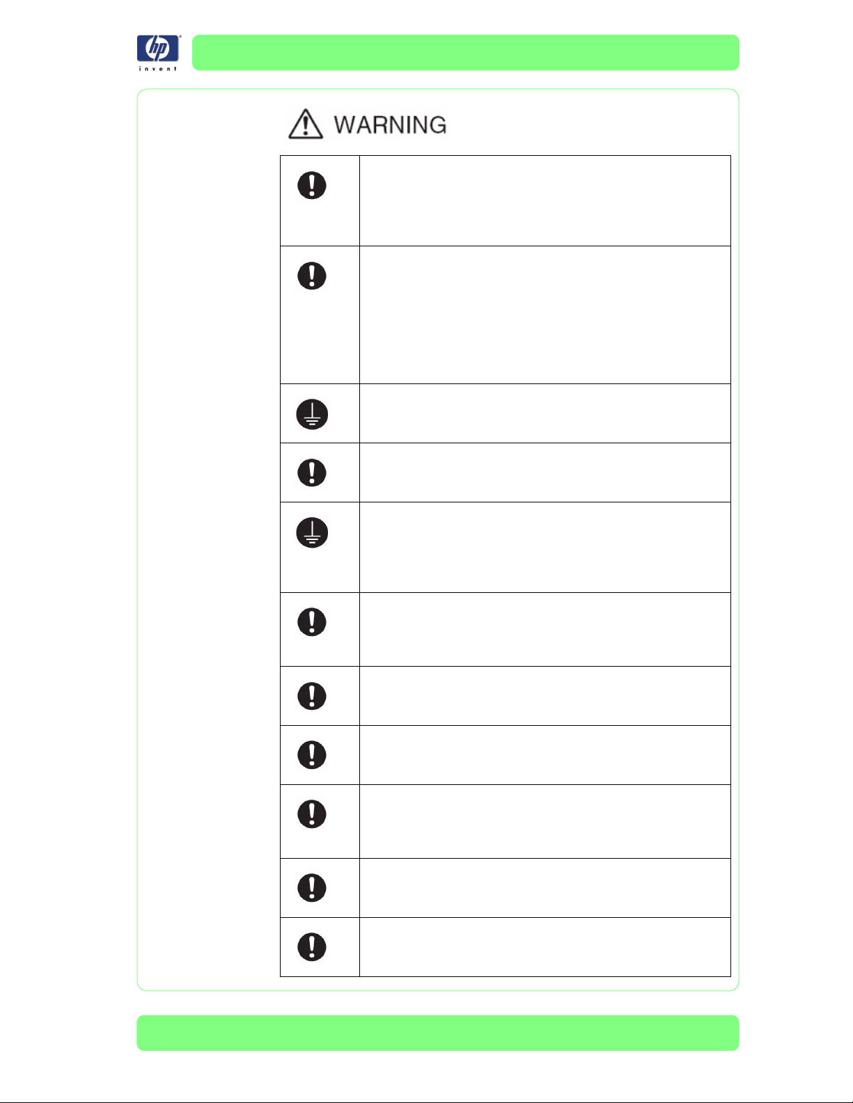
Inks used in the printer and liquids in the HP Cleaning and
Maintenance kits contain an organic solvent (ethylene glycol
monobutyl ether acetate, CAS No. 112-07-2). Observe all
local, state, and federal regulations related to the handling,
use, storage, and disposal of organic solvents.
Avoid contact between ink and skin, eyes, and clothing.
Immediately wash skin with soapy water.
Remove clothing soaked with ink from contact with skin.
Use an approved eye wash station if ink is splashed into
eyes and consult a doctor if necessary.
If an approved eye wash station is unavailable, flush
eyes with cold water and consult a doctor if necessary.
Be sure the printer is well-grounded. Failure to ground the
printer may result in electrical shock, fire, and susceptibility
to electromagnetic interference.
Ink and fluids used in the Cleaning and Maintenance Kits
are combustible. Do not use or store within 8 meters (25 feet)
of open flames, sparks, or other sources of ignition.
Switch power OFF, remove the power cords from the electric
outlets and allow the printer to cool before attempting to
remove any panels or covers. The printer contains high
voltage and hot components. Removal of panels or covers
may result in exposure to electric shock and burns.
Do not allow metal or liquids (except those used in HP
Cleaning and Maintenance Kits) to touch the internal parts
of the printer. Doing so may cause fire, electric shock, or
other serious hazards.
When shutting down the entire system, always turn OFF the
printer switch as well as the heater switch (breaker).
Use only an HP Waste Ink Bottle. The bottle must be installed
according to instructions or waste ink may overflow.
An HP Waste Ink Bottle must always be installed before
turning the printer ON. Automatic and manual service
cycles produce waste ink that must be contained in an HP
Waste Ink Bottle.
Always use both hands to remove and carry an HP Waste Ink
Bottle.
Keep the HP Waste Ink Bottle upright. Do not place on
tables or shelves where it could fall.
HP Designjet 10000s Series Printers Service Manual
3
Page 6
Waste ink is combustible. Keep an HP Waste Ink Bottle
containing waste ink away from open flames, sparks, or
other sources of ignition.
Never store waste ink in a glass container.
Never pour waste ink into a container filled with other
chemicals.
The HP Waste Ink Bottle contains organic solvents and must
be disposed of in compliance with all local, state, and
federal regulations.
Always securely replace the cap on a full or partially-full the
HP Waste Ink Bottle after removing it from the printer to
prevent ink spills.
4
HP Designjet 10000s Series Printers Service Manual
Page 7
Treat any media, paper, used cleaning and maintenance
supplies, and wipes soaked with ink as combustible
materials. Handle and dispose of properly.
Do not clean the printer with benzene or paint thinner. This
may damage the paint.
Wipe the printer clean with a soft cloth. A cloth moistened
with a neutral detergent may be used. Do not allow liquid to
enter the printer. This may create risk of fire and electrical
shock and cause a malfunction.
Never touch the printhead nozzles. They can be easily
damaged or clogged.
Do not touch heater surfaces in the paper path. This may
cause burns. Take care when touching printer components
near the heaters.
HP Ink Cartridges must be installed before the “Install By”
printed on the cartridge. Use of the Ink Cartridge 3 months
beyond the “Install By” date may cause deterioration in print
quality or a printer malfunction.
Do not separate the cap from a new HP Waste Ink Bottle.
The cap is needed to properly seal the HP Waste Ink Bottle
for disposal.
The level in the HP Waste Ink Bottle should be checked by
visual inspection to prevent overflow. If the waste ink level is
above the indication line, the bottle must be replaced with
an empty HP Waste Ink Bottle.
The use of safety glasses and gloves is recommended when
performing cleaning and maintenance operations.
HP Designjet 10000s Series Printers Service Manual
5
Page 8

Table of Contents
Table of Contents 1
Troubleshooting 1-1
System Error Codes 2-1
Head Adjustment 3-1
Maintenance Mode 4-1
Adjustments and Calibrations 5-1
Print Quality 6-1
Parts and Diagrams 7-1
Removal and Installation 8-1
Preventive Maintenance 9-1
6
HP Designjet 10000s Series Printers Service Manual
Page 9

Troubleshooting 1
Introduction 1-2
Troubleshooting System Error Codes 1-2
Performing a Service Test on a Failed Assembly 1-2
Performing the Necessary Service Calibrations or Adjustments 1-3
Solving Print Quality Problems 1-3
The Printer does not Power ON 1-3
Cover Sensors are not Working 1-3
The File Sent is Not Processed Immediately 1-3
Troubleshooting Media Jam Messages 1-4
Media Jams Occur Frequently 1-5
Print Speed is Very Slow 1-5
No Ink Message when there is Enough Ink 1-5
Abnormal Sound Coming from the Printer 1-5
Front Panel is Not Working 1-5
Heater Panel is Not Working 1-5
Solving Heater Problems 1-6
"Power ON Heater Power Switch" appears on Heater Panel 1-6
Heater Does NOT become Hot 1-6
Abnormal Temperature is Displayed 1-6
The Heater Temperature Becomes Extremely High 1-6
"Initializing" Continuously Appears on the Heater Panel 1-6
"Power Save Mode" Continuously Appears on the Heater Panel 1-7
Special Power On Procedure 1-7
Problems with Media End/Slack and TUR Sensors 1-7
Both NVRAM and Main PCA are Replaced Together 1-8
Solving Media Skew and Differential Banding Problems 1-10
Improving Image Quality when Frequently Printing Long Prints 1-22
1
HP Designjet 10000s Series Printer Service Manual
1-1
Page 10
Troubleshooting
Guide to Troubleshooting the Printer
Introduction
This chapter will guide you through the relevant steps to take when
troubleshooting the Printer.
Troubleshooting System Error Codes
Chapter 2 - System Error Codes contains a list of system error codes and
their respective descriptions and recommended corrective actions. Only try
one recommended action at a time and check if the error code has
disappeared.
If you have an error code which is not documented in this Service Manual or
you have an error which you cannot resolve, then report the error to the HP
Response Center or the nearest HP Support Office. When reporting the
error, have the following information ready:
Model and Serial Number of the printer.
Which firmware revision the printer is using.
The complete error number.
The System and History Prints
Which software application the customer is using (name, version, etc.).
.
Whenever an Error Message is displayed, you should try to
switch the Printer Off and then On again to see if the error
disappears. If the error disappears, there is no need to
troubleshoot the Printer any further.
Performing a Service Test on a Failed Assembly
If possible, always perform a Service Test on the component/assembly that
you are about to replace, just to make sure that is the actual component/
assembly that has failed.
If the test on that component/assembly passes, you should
NOT replace it.
For information on the Service Tests and how to use them see Chapter 4 -
Maintenance Mode.
1-2
HP Designjet 10000s Series Printer Service Manual
Page 11

Troubleshooting
Performing the Necessary Service Calibrations or
Adjustments
Is the printer calibrated or adjusted correctly after replacing a component?
For information on the Service Calibrations and Adjustments and how to use
them, see Chapter 5 - Adjustments and Calibrations.
Remember that certain Calibrations or Adjustments are
required even if an Assembly has been disassembled to gain
access to another Assembly or Component.
Solving Print Quality Problems
Whenever a Print Quality problem appears, it is advisable to print the Test
Print to help diagnose the problem. The Test Print will help you differentiate
between possible Printhead errors or mechanical problems. For information
on solving Print Quality problems see Chapter 6 - Print Quality.
The Printer does not Power ON
1 Check that the power cord is connected correctly to the Printer and to the
Power Socket.
2 Check that the Power Switch on the BACK of the Printer is in the ON
position.
3 Replace the Power Supply Unit
⇒ Page 8-45.
Cover Sensors are not Working
1 Perform the Sensors Test ⇒ Page 4-57.
2 Check if the cable for the faulty sensor is not damaged and is connected
correctly.
3 Replace the faulty Sensor.
The File Sent is Not Processed Immediately
1 Check that the USB Cable is connected correctly to the Computer and the
Printer and that it is NOT damaged.
2 Check that the Data LED on the Front Panel is flashing. If it is flashing and
nothing is printed, then maybe the file sent is corrupted or too big.
3 Make sure that the Printer is in the Online state when the file is sent. The file
will be rejected if the file is sent when the Printer is in the Offline state.
HP Designjet 10000s Series Printer Service Manual
1-3
Page 12

Troubleshooting
Troubleshooting Media Jam Messages
There are three different messages that appear on the Front Panel if a media
Jam occurs in the Printer:
Warning (0) Clear Media Jam.
Warning (1) Clear Media Jam.
Warning (2) Clear Media Jam.
Warning (0) Clear Media Jam
Over-current has been detected in the use of the Paper-Axis Motor. Try the
following:
1 Open the Rear Cover and check for any visible obstacles in the paper path.
If there is a wrinkled mass of paper inside the paper path, lift the
Pinchwheels (using the Media Lever) and clear the obstruction.
2 Check the Tension Bar to make sure that it is not applying too much weight
on the Media (check the User’s Guide for information on the correct usage
of the Tension Bars).
3 If sticky media is being used, then either use different media or use it with
the Liner.
4 Clean the Drive Roller and make sure that there is no paper dust or other dirt
trapped around the Drive Roller.
5
Check the tension of the Paper-Axis Belt and adjust it if necessary ⇒ Page 5-
14.
6 If this problem continues, replace the Paper-Axis Motor ⇒ Page 8-68.
Warning (1) Clear Media Jam
Over-current has been detected in the use of the Scan-Axis Motor. Try the
following:
1 Open the Rear Cover and check for any visible obstacles in the paper path.
If there is a wrinkled mass of paper inside the paper path, lift the
Pinchwheels (using the Media Lever) and clear the obstruction.
2 Check the Ink Supply Tubes Rail to make sure that it is correctly positioned (if
not correctly positioned, it could cause extra friction on the Carriage).
3 Check the tension of the Carriage Belt and adjust it if necessary.
4 Check the Encoder Strip to make sure that it is not dirty or damaged.
5 Check the Slider Rod to make sure that it not dirty.
6
Check the tension of the Scan-Axis Belt and adjust it if necessary ⇒ Page 5-
12.
7 If this problem continues, replace the Scan-Axis Motor ⇒ Page 8-72.
Warning (2) Clear Media Jam
This problem could be caused by a firmware error. Try the following:
1-4
1
Switch the Printer OFF and ON again and check if the message still appears
HP Designjet 10000s Series Printer Service Manual
.
Page 13

Troubleshooting
Media Jams Occur Frequently
1 Make sure that the paper type setting matches the type of paper loaded into
the Printer.
2 Open the Rear Cover and check for any visible obstacles in the paper path.
If there is a wrinkled mass of paper inside the paper path, lift the
Pinchwheels (using the Media Lever) and clear the obstruction.
3 Make sure that the Vacuum Fans are working correctly.
Print Speed is Very Slow
1 Make sure that the Printer is being used at temperatures of 20oC or higher
otherwise the Highlight mode is activated which will reduce the print speed
by up to 15%.
Print Stops After Each Pass
1 M
ake sure that the host PC and the Printer are correctly connected with a USB
2.0 Cable.
No Ink Message when there is Enough Ink
1 Make sure that the Ink Cartridge is installed correctly.
2 Check that the connector in the Ink Cartridge is NOT damaged.
3 Make sure that the Ink Cartridge Sensors are working correctly. Perform the
Ink Sensor Test
⇒ Page 4-58.
Abnormal Sound Coming from the Printer
1 One of the Motors in the Printer might be defective. Check that the Motors
are working correctly ⇒ Page 4-78.
2 Check that there are no foreign or loose objects inside the Printer.
3 Check the Carriage Base to make sure it is correctly installed.
Front Panel is Not Working
1 Make sure that the Front Panel Cable is connected correctly to the Front
Panel and to the Main PCA.
2 Make sure that the Front Panel Cable is NOT damaged.
3 Replace the Front Panel
⇒ Page 8-25.
Heater Panel is Not Working
1 Make sure that ALL Heater Panel Cables are connected correctly to the
Heater Panel.
2 Make sure that the Heater Panel Cables are NOT damaged.
3 Replace the Heater Panel
HP Designjet 10000s Series Printer Service Manual
⇒ Page 8-27.
1-5
Page 14

Troubleshooting
Solving Heater Problems
"Power ON Heater Power Switch" appears on Heater Panel
1 Check that the Heater Power Cable is connected and that the heater Power
Switch is switched On.
2 Replace the Heater Relay Assembly
3 Replace the Heater Panel
Heater Does NOT become Hot
1 Try performing the Heater Test ⇒ Page 4-96. If the Heater does not work
during the test, try the following:
⇒ Page 8-27.
⇒ Page 8-52.
Make sure that the Cable between the Heater Panel and the Heater Relay
Assembly is connected correctly and NOT damaged.
Make sure that the Heaters are connected correctly to the power voltage
alternation switch.
Replace the Heater Relay Assembly ⇒ Page 8-52.
Replace the Heater Panel ⇒ Page 8-27.
2 If the Heater does work during the Heater test, try the following:
Make sure that ALL Heater Panel Cables are connected correctly to the
Heater Panel.
Make sure that the Heater Panel Cables are NOT damaged.
Replace the Heater Panel ⇒ Page 8-27.
Replace the Main PCA ⇒ Page 8-36.
Abnormal Temperature is Displayed
1 Make sure that the Heater that is experiencing the abnormal temperature is
installed correctly. Check that the Heater Cable is connected correctly.
2 Replace the Heater Panel
3 Replace the Heater that is experiencing the abnormal temperature.
The Heater Temperature Becomes Extremely High
1 Make sure that the Heater that is experiencing the high temperature is
installed correctly. Check that the Heater Cable is connected correctly.
2 Replace the Heater Panel
3 Replace the Heater Relay Assembly
"Initializing" Continuously Appears on the Heater Panel
1 Make sure that the Cable between the Heater Panel and the Main PCA is
connected correctly and NOT damaged.
2 Replace the Heater Panel
3 Replace the Main PCA
⇒ Page 8-27.
⇒ Page 8-27.
⇒ Page 8-52.
⇒ Page 8-27.
⇒ Page 8-36.
1-6
HP Designjet 10000s Series Printer Service Manual
Page 15
Troubleshooting
"Power Save Mode" Continuously Appears on the Heater Panel
1 Make sure that the Cable between the Heater Panel and the Power Supply
Unit is connected correctly and NOT damaged.
2 Replace the Heater Panel
3 Replace the Power Supply Unit
4 Replace the Main PCA
⇒ Page 8-27.
⇒ Page 8-45.
⇒ Page 8-36.
Special Power On Procedure
When turning On the Printer, the Printer will follow the internal initialization
process, turning on the different systems and making the necessary system
checks. In order to troubleshoot the Printer the following Power On options
are available:
1 Press the Cancel key and Power On button - This will allow you to skip the
system check of the Printer.
2 Press the Cancel and Shift keys and Power On button - This will allow you
to skip the error recovery check of the Printer. You will be given the option to
enter the Maintenance Mode in order to troubleshoot the Printer by entering
a password:
This option is useful if you want to perform the following:
– Ink purging without installing media. In a normal power On situation,
the Printer cannot function without the media loaded.
– Recovery of a damaged NVRAM. By powering in the special power
On situation, the NVRAM can be recovered by entering the
Maintenance Mode and by performing the necessary steps to recover
the NVRAM.
W, X, Shift and OK.
MAINTENANCE MODE
PASSWORD?
Problems with Media End/Slack and TUR Sensors
If you see the following behavior when operating the Printer, it could be due
to the incorrect installation of the Media End/Slack and TUR Sensors:
1 On the Media Load side:
During media loading, when the Printer performs the slack check, the
printer continues to ask you to check the Slack.
If during media load, the media slack was too high, then at the end of the
media loading process, the Printer will display "End of Media" on the
Front Panel.
2 On the TUR side:
The Take-Up-Reel will not rotate.
In all these situations, you should double check that the Sensors have been
installed and connected correctly
HP Designjet 10000s Series Printer Service Manual
⇒ Page 8-220.
1-7
Page 16
Troubleshooting
Both NVRAM and Main PCA are Replaced Together
When both the NVRAM and the Main PCA are replaced at the same time,
mechanical correction value parameters, counters, calibrations, etc. are lost.
Whenever possible, this most be prevented by just replacing either the
NVRAM or the Main PCA. If for whatever reason, both the NVRAM and the
Main PCA are replaced together, you need to perform the following:
1 Make sure that the NVRAM and the Main PCA have been installed correctly.
2
Press the
3 Enter into the Maintenance Mode ⇒ Page 4-7.
Cancel
key and Power On button in order to skip the system check.
4 Press
5
the
Shift
key once and then
the W key to enter in to the Setup menu.
In the Setup submenu, scroll to "NVRAM Init" and press th
# NVRAM INIT
>
e OK
key.
6 You will need to confirm that you want to initialize the NVRAM by pressing
the OK key.
# NVRAM INIT
OK?
*
7 In the Setup submenu, scroll to "Language" and press the OK key.
# LANGUAGE
> ENGLISH
8
In the Language submenu, select "English" or "Japanese" and press the OK key.
# LANGUAGE
ENGLISH
*
9 Power Off the Printer.
10 Press the Cancel and Shift keys and Power On button in order to skip the
error recovery check of the Printer.
11 Perform the Line Sensor Test (⇒ Page 4-57) to register the platen’s maximum
value read by the Line Sensor to the NVRAM automatically.
1-8
12 Power Off the Printer, wait a few seconds and power On the Printer again.
13 You will need to check, and if necessary perform the following:
Wiping Position Calibration ⇒ Page 5-58.
Capping Position Calibration (the Cap Position Value must not be set to
0.0 mm in order for the Capping to work correctly) ⇒ Page 5-60.
Printhead Voltage ⇒ Page 4-23.
Printhead Row Value ⇒ Page 4-20.
Printhead to Printhead Value ⇒ Page 4-21.
Bidirection Definitions ⇒ Page 4-22.
HP Designjet 10000s Series Printer Service Manual
Page 17
Troubleshooting
Media Advance Print ⇒ Page 4-11.
Side Margin Position Calibration ⇒ Page 5-62.
Top Margin Position Calibration ⇒ Page 5-64.
14 In the Printhead Maintenance submenu, scroll to "Ink Charge Done" and
press the OK key.
# INK CHARGE DONE
> NO
15 In the Ink Charge Done submenu, select "Yes" to indicate that ink charge
has been completed and then press the OK key.
# INK CHARGE DONE
YES
*
16 In the Setup submenu, scroll to "Save Calibs" and press the OK key.
# SAVE CALIBS
>
17 You will need to confirm that you want to save the NVRAM Calibrations by
pressing the OK key.
# SAVE CALIBS
OK?
*
18 In the Setup submenu, scroll to "Save NVRAM" and press the OK key.
# SAVE NVRAM
>
19 You will need to confirm that you want to save the NVRAM contents by
pressing the OK key.
# SAVE NVRAM
OK?
*
20 Power Off the Printer, wait a few seconds and power On the Printer again.
HP Designjet 10000s Series Printer Service Manual
1-9
Page 18

Troubleshooting
Solving Media Skew and Differential Banding
Problems
The following information is not intended to be an exhaustive description of
the media loading process, but a list of the critical parts of the loading
process in order to avoid the following problems:
Media skew: when the media shifts from right to left or vice versa. This is
mainly visible when the vertical section of the media on the input side is
‘bending and flexing’, or when the media rolls incorrectly onto the TakeUp Reel.
Differential banding: when the banding is different from the right side to
the left side through the carriage movement.
1 Ensure that the roll of media is correctly loaded onto the Take-Up Reel and
the Main Scroller. This can be verified with the customer over the phone.
See the loading-guide table below for recommended settings to assist when
printing in the following methods:
Single-sided printing
Dual-sided printing
– Front side
– Back side (with liner)
– Back side (without liner)
Suggested
media path
Front Panel
mode
Main scroll
Tension Bar
HP does NOT recommend back-side printing without the liner.
Dual roll printing
Mesh printing
For a more in-depth description of the media-loading process, please refer to
the User’s Guide.
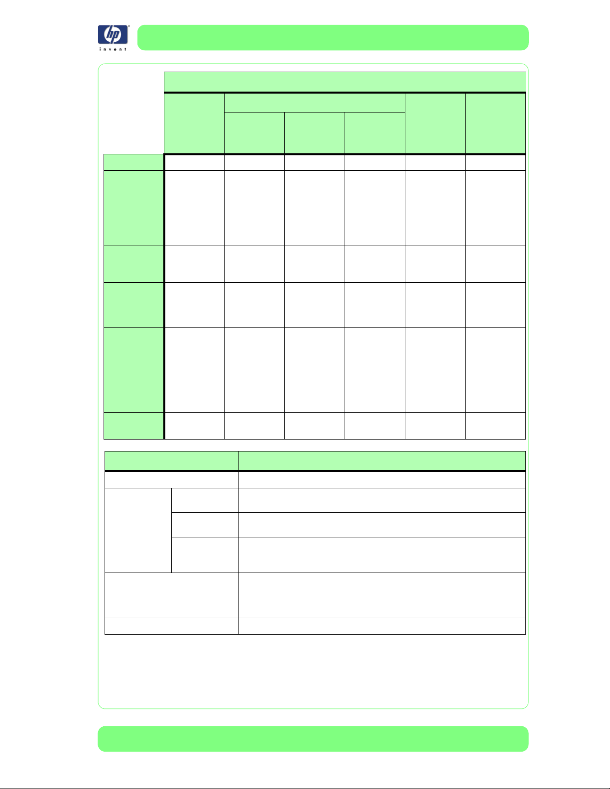
Loading-guide Table
Single-
side
MAIN FRONT BACKm BACKm DUAL BACKm
Depends on
media (see
media table)
Front side
(no liner)
Depends on
media (see
media table)
Dual-side Dual-roll Mesh
Back side
(without
liner)
Depends on
media (see
media table)
Back side
(with liner)
Depends on
media (see
media table)
Use two
tension bars
(one for each
slack)
Depends on
media (see
media table)
1-10
HP Designjet 10000s Series Printer Service Manual
Page 19
Loading-guide Table
Troubleshooting
Sub scroll
Take -up
setting
Media
Pressure
Lever
Carriage
height
Extra parts
needed
Vacuum
setting
Single-
Dual-side Dual-roll Mesh
side
Front side
(no liner)
Back side
(without
Back side
(with liner)
liner)
Not used Not used Not used Not used Not used Not used
Used to roll
the media
(optional),
depends on
media (see
media table)
Depends on
media (see
media table)
Low if the
media is
thinner than
0.5mm
None None None
High High High High High High
Used to roll
the media
(optional),
depends on
media (see
media table)
Depends on
media (see
media table)
Low if the
media is
thinner than
0.5mm
Used to roll
the media
(not
recommended)
Depends on
media (see
media table)
Low if the
media is
thinner than
0.5mm
Used to roll
the liner.
Media Width
Bar/Small
Flanges/2xOrings
Depends on
media (see
media table)
High
Special edge
guard hook,
Wiper side
edge guard,
Cap side
edge guard,
attachment
magnets (3)
Used to roll
the media
(optional),
depends on
media (see
User’s Guide
Chapter 3)
Depends on
media (see
media table)
Low if the
media is
thinner than
0.5mm
Flange spacer
(2), Flange
joint, Media
edge guards
(2)
Used to roll
the liner.
Media Width
Bar/Small
Flanges/2xOrings
Depends on
media (see
media table)
High
Special edge
guard hook,
Wiper side
edge guard,
Cap side
edge guard,
attachment
magnets (3)
Printing method Comments
Single-side None
Dual-side
Dual-roll
Mesh
Front side (no
liner)
Back side (no
liner)
Back side (with
liner)
Two lines at the end of each plot will be printed.
Rotate the image in the RIP before sending it. For alternative dual-side methods,
see Chapter 4 of the User’s Guide.
Rotate the image in the RIP by 180 degrees before sending it. Set the DETECT
WIDTH setting to NONE. Use the Separator bar. For alternative dual-side
methods, see Chapter 4 of the User’s Guide.
The maximum-media roll width is 50". Use identical media rolls (type and width).
The wound diameter on each roll must be the same. Only print on the outside of
the media rolls. For alternative dual-roll methods, see Chapter 3 of the User’s
Guide.
Set the DETECT WIDTH setting to NONE. Use the Separator bar.
HP Designjet 10000s Series Printer Service Manual
1-11
Page 20
Troubleshooting
Media Table
Media Main scroll Tension
Bar (*)
Banner 1/2 media width
PVC (S/A Vinyl) Shortest (16in)
Textile 1/2 media width
Premium backlit film Shortest (16in)
Canvas 1/2 media width
Universal photo realistic Shortest (16in)
(*) For sticky media, consider the following points:
Use a longer Tension Bar (up to 90% of the media width).
Make the Tension Bar heavier by adding media. The maximum allowable
Tension Bar weight is 3Kg.
Take-up Setting Media Pressure
Lever
Media Width Bar /
Small Flanges / 2xOrings
Tension Bar not used /
Big Flanges
1/2 Media Width Bar
/ Small Flanges / 2xOrings
Tension Bar not used /
Big Flanges
Media Width Bar /
Small Flanges / 2xOrings
Tension Bar not used /
Big Flanges
Down (Normal)
Down (Normal)
Up (Low)
Down (Normal)
Down (Normal)
Down (Normal)
1-12
HP Designjet 10000s Series Printer Service Manual
Page 21
Troubleshooting
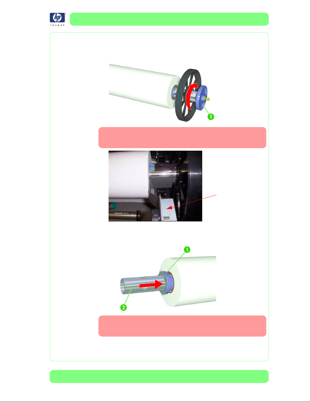
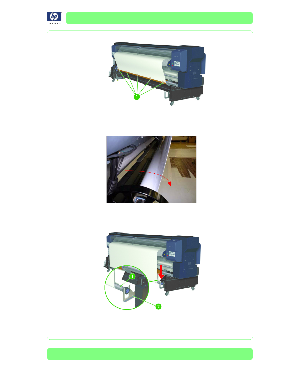
a Ensure that the core of the media is correctly fixed onto the Main Scroller.
To lock the media roll to the main scroller, turn the hand-wheel (1) of the
main scroller clockwise until it reaches the stop. This must also be done
for the Take-Up Reel if it is used.
Use the Media Positioning Tool shown in the picture below to
leave additional space between the media roll and the drive
wheel. This will help to position the flange on the TUR side.
b Ensure that the toothed flange spacer (1) is correctly inserted on the left
side of the roll on the Main Scroller (2). This must also be done for the
Take-Up Reel if it is used.
If the toothed flange spacer is not inserted correctly, the core of
the media will not rotate in a circular motion, but will rotate in
an elliptical motion, which will result in media skew.
HP Designjet 10000s Series Printer Service Manual
1-13
Page 22
Troubleshooting
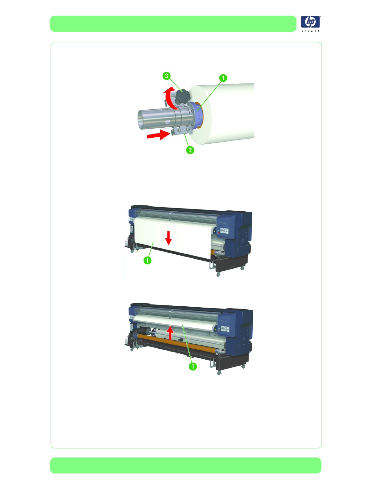
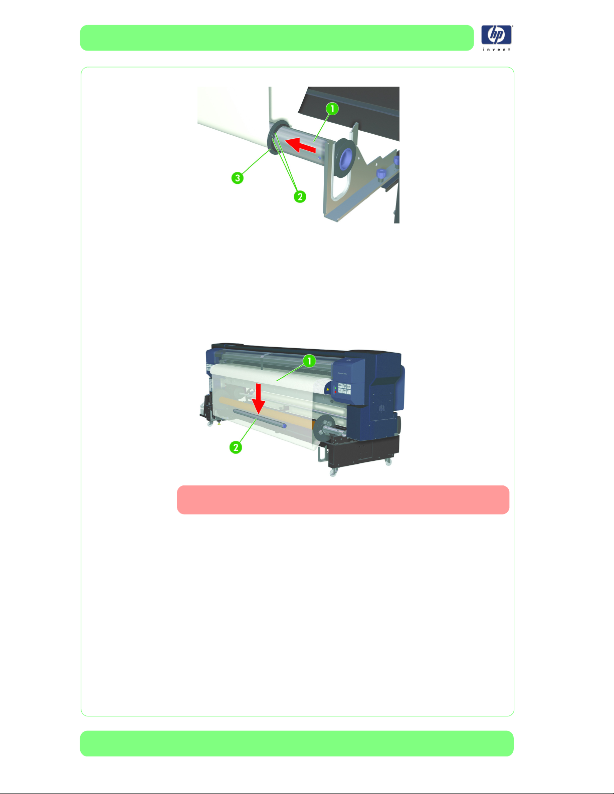
c Ensure that the locking knob (3) is fully tightened on the flange stopper
(2) to lock it to the flange spacer (1) and the main scroller. This must also
be done on the Take-Up Reel if it is used.
2 During the loading process of the media, ensure that the media is correctly
wound into the roll.
a Use the black media advance switch at the front of the printer to feed the
media through the media feeder until it almost reaches the floor. Do not
close the Media Lever yet.
1-14
b Use the white rewind switch at the front of the printer to rewind the media
(1) until it is just protruding from the rear cover.
HP Designjet 10000s Series Printer Service Manual
Page 23
Troubleshooting
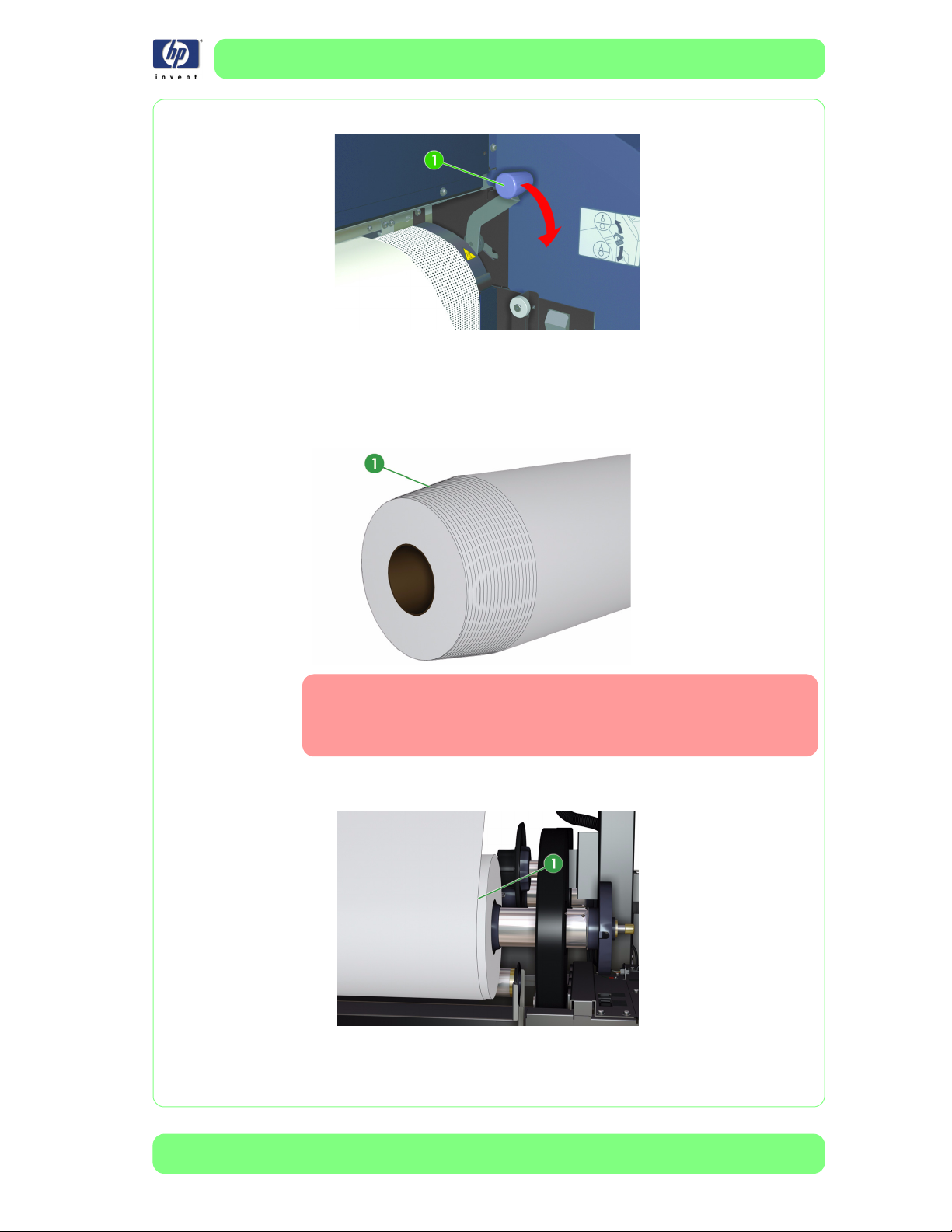
c Lower the Media Lever and follow the instruction from the Front Panel.
3 Ensure that the media is tightly rewound onto the roll.
If the media (1) is not correctly rewound onto the roll as explained in step
2b, do not use the roll. The probability of skew will be very high if you
choose to continue. You can repeat steps 2a - 2c to get the roll to load
straight and parallel with the ends of the cardboard core.
After rewinding the media, verify that the media is correctly rewound onto the Main Scroller. If the edge of the core of the media (1) is not straight, as shown in the picture, this will
generate skew.
HP Designjet 10000s Series Printer Service Manual
1-15
Page 24
Troubleshooting
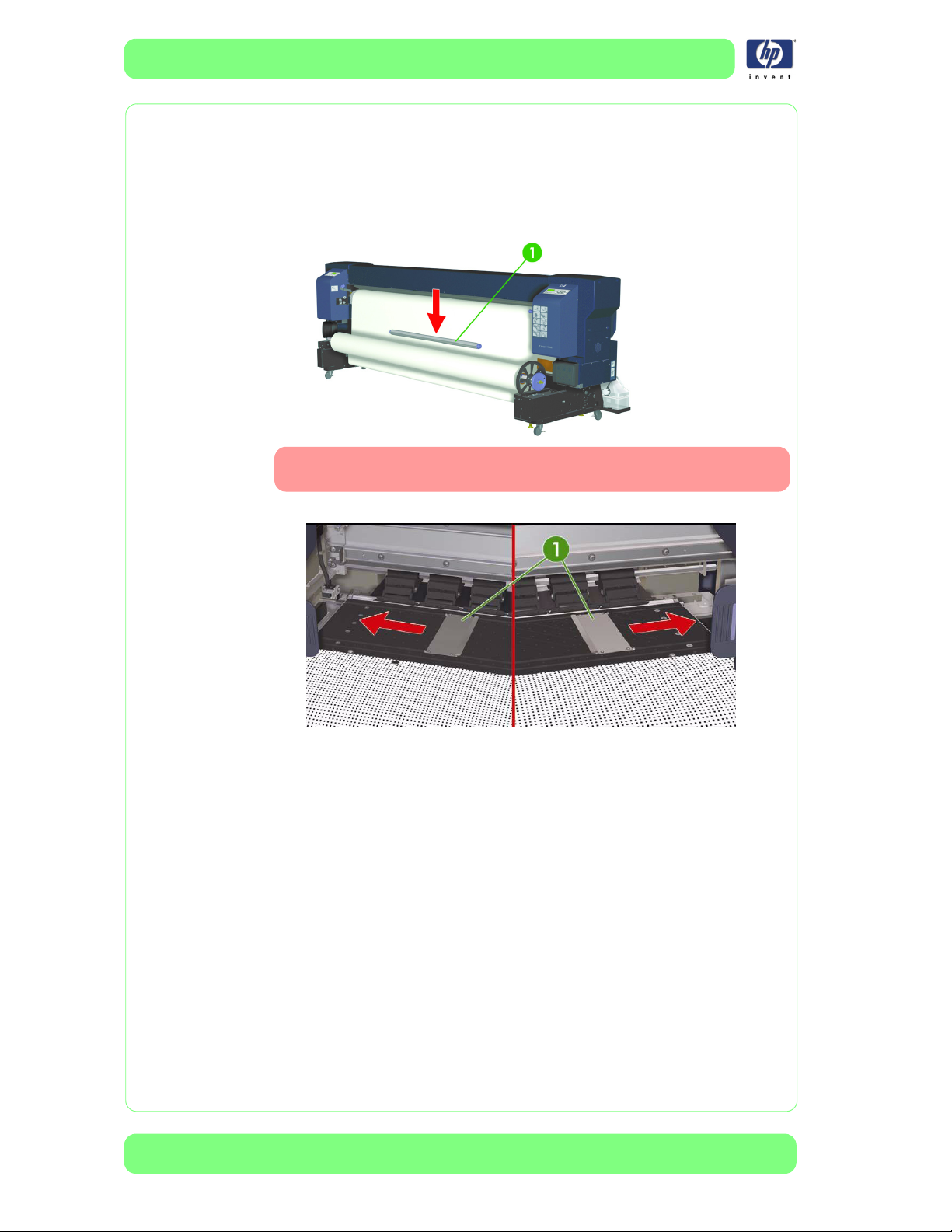
4 Ensure that the correct length of tension bar is being used in the slack area
of the media.
The tension bar must be half the width of the media. If the tension bar is too
big or too small it can create skew. Make sure the tension bar (1) is
positioned in the center of the slack area of the media or the media may not
feed smoothly.
When using PVC (Vinyl), it is recommended that you use a short
tension bar (16”, 40cm).
5 Ensure that the Edge Guards (1) are correctly installed.
1-16
6 When using the Take-Up Reel, ensure that the correct process is being
performed.
a When taping the media onto the Take-Up Reel, take the following points
into consideration:
Ensure that the media is advanced towards the empty core by using the
feed entry from the Front Panel (the Media Load Lever should be closed.
The media must remain fully loaded).
Ensure that the media is straight.
Ensure that you first tape the middle of the media to the core, and then
tape from the inside, until you reach the outside edges of the media.
Do not create any additional tension on the media when you are taping.
HP Designjet 10000s Series Printer Service Manual
Page 25
Troubleshooting
Carefully apply the tape to the media and core.
b Use the Front Panel Feed Menu to feed more media.
c Manually turn the Take-Up Reel a few times. This is not mentioned in the
user's guide, but should be noted. This is done to ensure that no lengths
of tape fall off, which could create skew.
d Ensure that the correct flanges are used for the loaded media. For most
media (with the exception of film), the small flanges can be used. Using
the big flanges on some media can cause skew. The tension bar (1)
should be placed on the tension bar guides (2).
HP Designjet 10000s Series Printer Service Manual
1-17
Page 26
Troubleshooting
e Use the O-rings (2) to maintain the flanges on the Take-Up Reel.
f When using PVC media (1), taking the following points into
consideration will help to reduce skew:
Use the large, black Media Tube Flanges on the Take-Up Reel.
Do not put the tension bar on the tension-bar guides.
Use the tension bar without flanges (2) or try removing it to see if it
reduces the skew.
Adjust the length of the tension bar to approximately half the width of the
media, and then position it in the slack area as shown below.
1-18
When using PVC (Vinyl), it is recommended that you use a short
tension bar (16”, 40cm).
7 Use the dryer to dry the media before it is wound onto the Take-Up Reel.
Images printed with a lot of ink take longer to dry and can cause the TakeUp Reel core to stick, putting unwanted tension on the media. Using the
dryer will help to keep the printed media from sticking to the core and will
help to reduce skew.
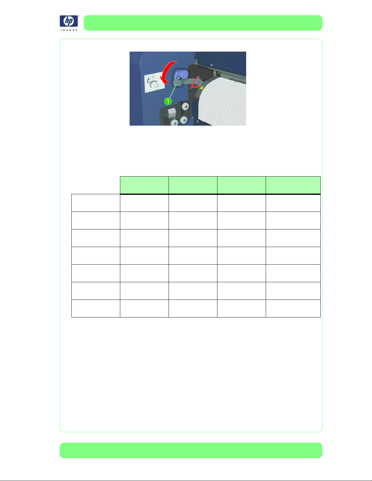
8 Verify the position of the Media-Pressure Lever.
Verify the position of the Media-Pressure Lever on the right side of the printer.
By default it should be in the lowered position, which adds pressure to the
media. However, for certain media, such as textile media, the MediaPressure Lever should be set at the raised position, which reduces pressure
HP Designjet 10000s Series Printer Service Manual
Page 27
Troubleshooting
on the media.
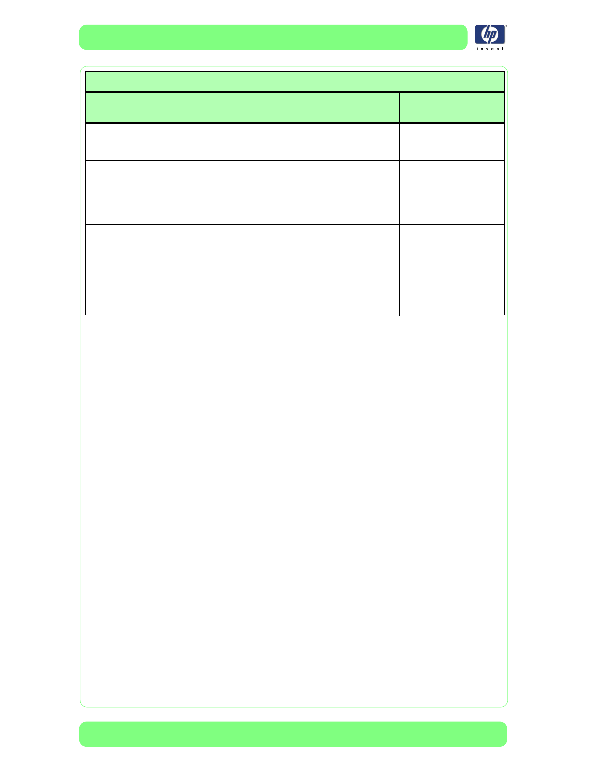
The table below shows recommended settings for the Tension Bar, Flanges,
and the Media-Pressure Lever for a variety of HP media which have been
tested and proven to provide the best image-quality results. Consult the table
to choose a setting for a media similar to those listed when using third-party
media.
Premium scrim
Banner
Universal scrim
Banner
Premium self
adhesive vinyl
Textile (without
backing)
Canvas
Universal photo
realistic
Premium Backlit
Film
Main scroll
Tension Bar
Half media
width
Half media
width
Shortest (16
inches)
Half media
width
Half media
width
Shortest (16
inches)
Shortest (16
inches)
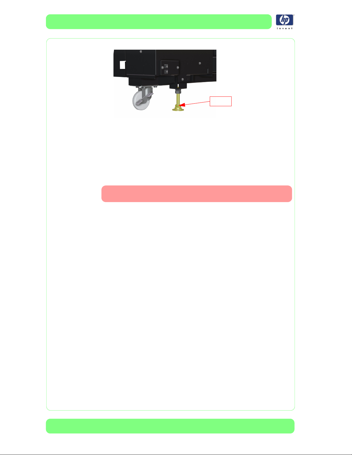
9 Verify the positions of the levelers.
Ensure that the levelers are correctly adjusted and touching the ground.
There are 2 levelers per unit: one under the Main Scroller unit and one
TUR Tension
Bar
Media width
Bar
Media width
Bar
Not used Big flanges Down (Normal)
Media width
Bar
Media width
Bar
Not used Big flanges Down (Normal)
Not used Big flanges Down (Normal)
Take-up
Flanges
Small flanges
2x O-rings
Small flanges
2x O-rings
Small flanges
2x O-rings
Small flanges
2x O-rings
Media
Pressure Level
Down (Normal)
Down (Normal)
Up (Low)
Down (Normal)
HP Designjet 10000s Series Printer Service Manual
1-19
Page 28
Troubleshooting
under the Take-Up Reel.
Leveler
10 Changing the Fan-Vacuum Level might help.
From the Front Panel select Media-Reg, select Vacuum Fan, and then
select Low, Middle, or High.
If the previous section does not solve the skewing
To know if the Take-Up Reel is generating skew, try printing without the TakeUp Reel. If there is no skew, focus must be placed on how to set-up media on
the Take-Up Reel.
If the case can not be solved through the phone call, the following must be performed by an ‘On site customer engineer’.
1 First verify that the customer is correctly following all of the necessary steps
for loading media (refer the customer to the User's Guide and the advice
presented in this section).
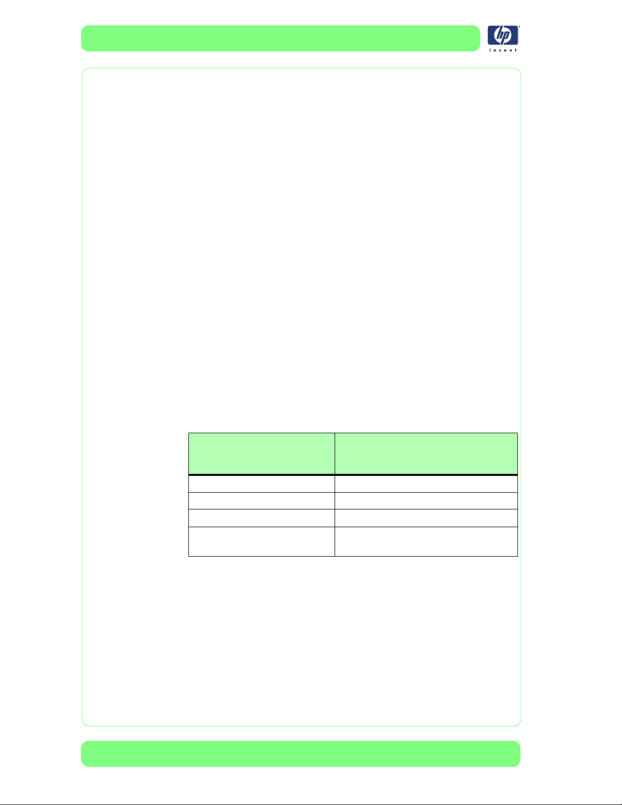
2 Ensure that the rear heater is correctly installed.
Ensure that the screws that are used to secure the heater to the printer are
correctly inserted, and ensure that the heater border is correctly inserted into
1-20
HP Designjet 10000s Series Printer Service Manual
Page 29
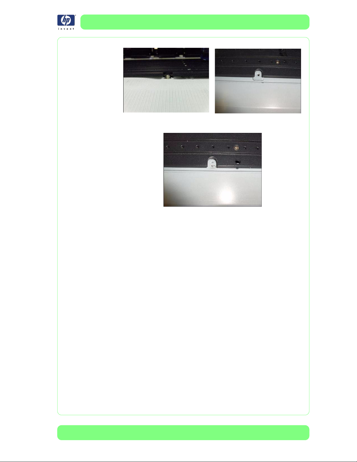
the slot.
Troubleshooting
Incorrect installation
Correct insertion of the heater into the support slot
3 Perform the Media Feed and Take-Up-Reel Unit Adjustment
⇒
Page 5-30
.
HP Designjet 10000s Series Printer Service Manual
1-21
Page 30
Troubleshooting
Improving Image Quality when Frequently Printing
Long Prints
Customers who frequently print long prints (more than 10m/33ft) need to
configure some specific printer settings to keep the printheads in good
condition and avoid image-quality issues.
Normal Printer Operation
Low-solvent printheads require frequent maintenance and servicing to keep
the nozzles from becoming clogged. Therefore, in addition to the customer’s
required daily maintenance tasks, the printer performs automatic, periodic
servicing between prints.
During the automatic servicing, the printer performs the following services:
Primes the printheads to unblock any temporarily blocked nozzles.
Wipes the nozzle plate to remove any residual solvent ink that may have
accumulated around the nozzles to reduce the chances of nozzle
blockage with additional usage.
Opens the capping units to remove any ink accumulation inside the caps.
These processes are necessary to ensure the correct functioning of the
printhead, which affects the image quality of the printed image.
When printing an average job, automatic servicing is done between prints.
After a predetermined length of media has been printed, the printer
performs the automatic servicing procedure. The amount of media that is
printed on before the servicing is triggered depends on which print mode is
selected:
Print Mode Selected
(Bidirectional)
Draft (2 passes) 18m/60ft
Normal (4 passes) 9m/30ft
High Quality (8 passes) 4.5m/15ft
High Quality 200% (16
passes)
Long prints (more than 10m/33ft) operation
Canceling the automatic servicing is not recommended. Over time, doing so
will negatively impact printhead performance and image quality.
As the nozzle plate accumulates ink from the tails of the drops of solvent ink,
and the accumulation of ink in the capping units, image quality starts to
deteriorate.
Amount of media printed
before printhead servicing is
performed
2.25m/7.4ft
1-22
The accumulation of ink on the nozzle plate creates "nozzle-outs" that can
HP Designjet 10000s Series Printer Service Manual
Page 31

Troubleshooting
result in banding on vinyl material, and color deviation on textiles.
Dirty nozzle plate due to lack of regular servicing
This problem can be resolved by stopping the printer and allowing it to
perform minimal printer maintenance.
Longer-term side effects can occur when frequently printing long plots. For
more details on long-term side effects, see Page 1-26.
How to correctly print frequent jobs of length longer than
10m/33ft
There are three different scenarios to consider:
1 The customer is printing individual jobs nested as one file. Printing in this
manner is not recommended because it puts unnecessary stress on the
printhead. The benefits of printing in this manner are likely to be offset by the
need re-print all or some parts of the printout.
2 The customer is printing large tiles. When printing large tiles, ensure that the
“Send tiles as independent job” setting is selected in the RIP. If it is not
selected, the RIP will send the tile as one job, which will not allow the printer
to perform servicing between the tiles.
3 The customer is printing single jobs that are longer than 10m/33 ft. When
printing jobs of this size, the printer requires resting periods, during which it
performs printhead servicing.
As a guideline, the default resting period is 10 seconds for every 10 meters
of printed media. The length of printed media per rest can be shortened or
lengthened based on the amount of ink applied during printing.
For more information on defining periodic printhead resting periods, see
Page 1-24. Be aware that printhead resting periods can result in unwanted
side effects such as banding. For more information on banding under these
circumstances, see Page 1-25.
With any of these three printing scenarios, there are other factors to consider
to ensure correct printhead functionality:
Ensure that the environmental temperature is above 20ºC/69ºF.
Ensure that the color stripe is set to ON.
HP Designjet 10000s Series Printer Service Manual
1-23
Page 32

Troubleshooting
Ensure that the Central Platen Heater temperature is below 40ºC/104ºF.
Ensure that the arrow on the Fan Guard Lever is aligned with the edge of
the media, to avoid excessive hot air blowing on to the nozzle plate.
Select the “Send tiles as independent job” setting in the
Postershop RIP
Define a periodic printhead resting period
The printer has the following two settings:
1 #PH REST PERIOD: The setting defines how many print cycles are made
before the printer rests. One cycle equals one pass.
The recommendation is to allow the printer to rest every 10m/33 ft, but the
length must be converted into cycles based on the print mode.
Printmode DRAFT
Number of
passes
2 passes 4 passes 8 passes 16 passes
Number of
cycles for 10/
550 cycles 1,100 cycles 2,200 cycles 4,400 cycles
m33ft
2#PH REST TIME: This setting defines the amount of time (in seconds) that
the printer rests during each resting period.
Here is an example to illustrate the correct settings based on the recommendations in
the table above.
consist of 5 tiles, each 20m in length, on
FINE DRAFT FAST
NORMAL
H-QUALITY HDENSITY
H-QUALITY2 HDENSITY2
Imagine that the customer is going to print a job which will
HP Premium Scrim Banner medium
1-24
HP Designjet 10000s Series Printer Service Manual
Page 33

(Q8678A), with the print mode set to Normal (4 passes).
These settings are in the MEDIA REG (media registration) menu.
Media and print mode settings
Because the print mode is set to
NORMAL, there will be 1,100 cycles
per 10m/33ft of media printed. The
rest time is set to 10 seconds.
Banding while stopping
Troubleshooting
The previous recommendations will ensure the health of the printhead and
image quality, allowing results like that shown below.
However, side effects may occur when using the aforementioned settings.
The image below illustrates banding that can occur during the printer resting
HP Designjet 10000s Series Printer Service Manual
1-25
Page 34

Troubleshooting
periods.
This type of banding is not usually visible when viewed from a distance.
Depending on the media type and the printed image, the customer might
experience a slight color change in the image (banding) where the
printhead was positioned during the printer resting period. The banding is
most likely to occur when printing dark images on textiles.
Banding can be reduced by testing different rest times, but the main factor is
the type of media being printed on. Banding does not occur, for example,
when printing on HP Self-Adhesive Vinyl.
Possible long-term side effects
Failure to follow the printhead maintenance recommendations will result in
image-quality issues; the most significant and immediate of which being
banding or color shift in the middle of a print. However, long-term failure to
follow the maintenance recommendations will result in printhead damage.
To maintain the health of the nozzles, the printhead spits into the capping
units after every other pass. The ink accumulates in the capping units until
printhead servicing, at which time they are emptied.
1-26
If printhead servicing is not done during the printing of long prints, two
unwanted scenarios can occur.
1 The Printhead Nozzle Plate can come in contact with the ink while printing,
HP Designjet 10000s Series Printer Service Manual
Page 35

resulting in nozzle blockage.
2 The ink in the capping units can overflow. When this occurs, the ink seeps
below the capping units where it dries and accumulates. Under these
circumstances the printer is not able to adequately perform the capping and
priming procedures. Over time, the nozzles become blocked.
Dry ink below capping units
Ink overflow
To verify that the capping units are working correctly, follow these steps:
1 Perform the PH WASH procedure.
2 Turn the printer off by using the hard ON/OFF switch at the front of the
printer, below the front heater.
3 Remove the covers to access the capping station.
4 Manually lower the capping station.
Troubleshooting
5 The capping units should not be empty. If any of the capping units are
empty, they are not functioning correctly.
Dry ink below capping units
If the capping units are not functioning correctly, the entire capping station
must be replaced. Adequate maintenance practices are the best way to
assure maximum printhead life and image quality.
HP Designjet 10000s Series Printer Service Manual
1-27
Page 36

Troubleshooting
1-28
HP Designjet 10000s Series Printer Service Manual
Page 37

System Error Codes 2System Error Codes 1
Introduction 2-2
Self-Diagnostic Errors at Power On 2-3
System Error Codes 2-8
Heater Error Codes 2-17
System Error Codes 2-20
2
HP Designjet 10000s Series Printer Service Manual
2-1
Page 38

System Error Codes
System Error Codes
Introduction
The following pages contain a list of error codes and their respective
descriptions and recommended corrective actions. Only try one
recommended action at a time and check if the error code has disappeared.
If you have an error code which is not documented in this Service Manual or
you have an error which you cannot resolve, then report the error to the HP
Response Center or the nearest HP Support Office. When reporting the
error, have the following information ready:
Model and Serial Number of the printer.
Which firmware revision the printer is using.
The complete error number.
The Service Configuration Print
The Current configuration sheet.
Which software application the customer is using (name, version, etc.).
.
Whenever an Error Message is displayed, you should try to
switch the Printer Off and then On again to see if the error
disappears. If the error disappears, there is no need to troubleshoot the Printer any further.
2-2
HP Designjet 10000s Series Printer Service Manual
Page 39

System Error Codes
Self-Diagnostic Errors at Power On
When the Printer is powered up, it performs the Boot-Up sequence which
initializes the major components of the Printer. If for some reason the BootUp sequence fails because a component has failed to initialize, an error
code will appear on the Front Panel.
INITIALIZING
E Ennnn
The Boot-Up error codes are hexa-decimal based numbers and correspond
to bits which are explained in the following table:
Bit Error Code (nnnn) Diagnosis
00001Internal RAM
10002SRAM
2 0004 Flash ROM
30008PIO
40010NVRAM
5 0020 FPGA (Main PCA)
6 0040 FPGA (Carriage PCA)
70080ASIC CONF (Main PCA)
8 0100 ASIC CONF (Carriage PCA)
90200DRAM
10 0400 USB Register
11 0800 Power Supply
13 2000 Add-ON (HEB2) Control PCA
14 4000 Cap Position Adjustment Value
15 - Reserved
When multiple errors occur during the Boot-Up sequence, the error codes
are added together and only one hexa-decimal figure is displayed on the
Front Panel. For example, if the NVRAM and the Power Supply fail
during the Boot-Up sequence, the error code E0810 will be displayed.
NVRAM (0010) + Power Supply (0800) = 0810
Each error code and it’s appropriate corrective actions are explained on the
following pages.
HP Designjet 10000s Series Printer Service Manual
2-3
Page 40

System Error Codes
Boot-Up Error: Internal RAM (0001)
Problem
Description:
Corrective Action: Try the following:
Boot-Up Error: SRAM (0002)
The read/write of the RAM on the Main PCA was diagnosed and an error
was detected.
Replace the Main PCA
⇒
Page 8-36.
Problem
Description:
Corrective Action: Try the following:
Boot-Up Error: Flash ROM (0004)
Problem
Description:
Corrective Action: Try the following:
Boot-Up Error: PIO (0008)
Problem
Description:
Corrective Action: Try the following:
Boot-Up Error: NVRAM (0010)
The read/write of the SRAM on the Main PCA was diagnosed and an error
was detected.
Replace
The program area in the Flash ROM is sum-checked, and it could not be
read, causing an error.
Reinstall the Firmware (Printer and Boot Firmware).
If the Error continues, replace the Main PCA
The read/write of a specific Parallel I/O (PIO) was tested and an error was
detected.
Replace the Main PCA ⇒ Page 8-36.
the Main PCA ⇒
Page 8-36
.
⇒
Page 8-36.
Problem
Description:
Corrective Action: Try the following:
2-4
Problems with the NVRAM detected.
If multiple errors have occurred that include the NVRAM error, try to resolve
the other errors first. After resolving the other errors (except NVRAM),
switch the Printer Off.
Switch the Printer On again and only the NVRAM error recovery will be
performed.
If System Error Code 11Ax appears when the Printer is turned On, then
refer to Page 2-11.
Replace NVRAM ⇒ Page 8-41.
Replace Main PCA ⇒ Page 8-36.
HP Designjet 10000s Series Printer Service Manual
Page 41

Boot-Up Error: FPGA (Main PCA) (0020)
Problem
Description:
Corrective Action: Try the following:
Boot-Up Error: FPGA (Carriage PCA) (0040)
The read/write of the FPGA-ATG (Band Memory) and FPGA-RSM (Mask
Memory) registers on the Main PCA was diagnosed and an error was
detected.
Replace the Main PCA ⇒ Page 8-36.
System Error Codes
Problem
Description:
Corrective Action: Try the following:
Boot-Up Error: ASIC CONF (Main PCA) (0080)
Problem
Description:
Corrective Action: Try the following:
Boot-Up Error: ASIC CONF (Carriage PCA) (0100)
Problem
Description:
The read/write of the FPGA-PTC (Print Timing Controller) and FPGA-PDD
(Print Data Distributor) registers on the Carriage PCA was diagnosed and an
error was detected.
Replace the Carriage PCA ⇒ Page 8-97.
Make sure that the Carriage Cable is correctly connected.
Replace the Main PCA ⇒ Page 8-36.
The program load from the Flash ROM on the Main PCA to the FPGA on the
Main PCA or sum-check was not performed correctly and an error occurred.
Reload the ASIC program from the IC Card.
Replace the Main PCA ⇒ Page 8-36.
The program load from the Flash ROM on the Main PCA to the ASIC on the
Carriage PCA or sum-check was not performed correctly and an error
occurred.
Corrective Action: Try the following:
Reload the ASIC program from the IC Card.
Make sure that the Carriage Cable is correctly connected.
Replace the Carriage PCA
Replace the Main PCA ⇒ Page 8-36.
Boot-Up Error: DRAM (0200)
Problem
Description:
Corrective Action: Try the following:
HP Designjet 10000s Series Printer Service Manual
The read/write of the image band memory on the Main PCA was
diagnosed and an error was detected.
Replace the Main PCA ⇒ Page 8-36.
⇒
Page 8-97.
2-5
Page 42

System Error Codes
Boot-Up Error: USB Register (0400)
Problem
Description:
Corrective Action: Try the following:
Boot-Up Error: Power Supply (+36V, +24V, +12V) (0800)
The read/write of the USB controller on the Main PCA was diagnosed and
an error was detected.
Replace the Main PCA ⇒ Page 8-36.
Problem
Description:
Corrective Action: Try the following:
The power supplies of +36, +24 and +12 V were diagnosed and could not
be detected.
Open the Electronics Cover and check LED 11 and LED 13.
If both LED 11 and LED 13 are OFF, then try the following:
– Check the Interlock Switches to make sure they are installed/connected
correctly. Make sure that the Rear Cover lips (that activate the Interlock
Switches) are not bent and that the Rear Cover is closed correctly.
– If the Interlock Switches are installed and connected correctly, then
replace the Main PCA
If both LED 11 and LED 13 are ON, then try the following:
– Check whether the correct voltages are supplied from the power source
(refer to the table below). If the correct voltages are not supplied, then
replace the Power Supply Unit ⇒
– It is possible that this error occurred because of a faulty Main PCA.
Replace the Main PCA ⇒ Page 8-36.
– Check whether the motors have been short-circuited by testing +24 V. If
+24 V is not supplied then replace both Scan-Axis/Paper-Axis Motors.
If error continues, replace the Main PCA ⇒ Page 8-36.
⇒ Page 8-36
Page 8-45.
.
2-6
HP Designjet 10000s Series Printer Service Manual
Page 43

System Error Codes
Power Line Measuring Position
(on the Main PCA)
+1.5 V TP70 +1.45 V to +1.55 V
+3.3 V TP69 +3.20 V to +3.40 V
+5 V REF TP36 +4.90 V to +5.10 V
5 V TP35 +4.75 V to +5.25 V
+12 V TP50 +11.00 V to +13.00 V
+24 V TP34 +23.00 V to +25.00 V
+36 V TP93, TP33 +35.00 V to +37.00 V
Boot-Up Error: Add-On (HEB2) Control PCA (2000)
Problem
Description:
Corrective Action: Try the following:
Problems with the Add-On (HEB2) Control PCA detected.
Make sure the HEB2 Board Interface Cable is connected correctly and is
not damaged
Replace the
If the error continues, replace the Main PCA ⇒ Page 8-36.
Add-On (HEB2) Control PCA ⇒
Normal Value
Page 8-45.
Boot-Up Error: Cap Position Adjustment Value (4000)
Problem
Description:
Corrective Action: Try the following:
This error appears when the Cap Position Adjustment Value is set to zero.
To clear this error:
– Turn the Printer ON in error skip mode by holding down the Cancel
and Shift keys and pressing the ON button.
– Enter the Password to enter the Maintenance Mode menu:
and OK
– Set the correct Cap Position value (so that it is not set at 0.0 mm) ⇒
Page 4-13.
.
W, X, Shift
HP Designjet 10000s Series Printer Service Manual
2-7
Page 44

System Error Codes
System Error Codes
A System Error Code appears on the Front Panel when a component of the
Printer has failed during normal usage. Each System Error Code and it’s
appropriate corrective actions are explained on the following pages.
System Error: System Error 1110: GA_ATG Block Clear Error
Problem
Description:
Corrective Action: Try the following:
System Error: System Error 1111: GA_ATG DMA Transfer Error
The ATG band memory block erase does not end. This error is checked
during Boot-Up sequence and printing.
Replace the Main PCA ⇒ Page 8-36.
Problem
Description:
Corrective Action: Try the following:
System Error: System Error 112x: Vacuum Fan Error
Problem
Description:
Corrective Action: Try the following:
There is a problem with the USB communication. This error is checked during
printing.
Turn off the printer, and then turn it on again.
Make sure that the host PC and the Printer are correctly connected with a
USB 2.0 Cable.
If the error occurs frequently, the problem might be that the RIP is hanging.
Make sure the RIP is functioning correctly.
Make sure that the printer is running the latest firmware.
Replace the Main PCA ⇒ Page 8-36.
x = 0: The Vacuum Fan (Wiping Side) has failed.
x = 1: The Vacuum Fan (2nd Fan from Wiping Side) has failed.
x = 2: The Vacuum Fan (Center of the Platen) has failed.
x = 3: The Vacuum Fan (2nd Fan from Capping Side) has failed.
x = 4: The Vacuum Fan (Capping Side) has failed.
Make sure that the failing Vacuum Fan Cable is connected correctly and is
not damaged
Replace the failing Vacuum Fan ⇒ Page 8-35.
If the error continues, replace the Add-On (HEB2) Control PCA (for errors
where x = 0 or 1) and the Main PCA (for errors where x = 2, 3 or 4).
System Error: System Error 1130: DMA Controller Error.
Problem
Description:
Corrective Action: Try the following:
2-8
There is a problem with the USB communication.
Turn off the printer, and then turn it on again.
HP Designjet 10000s Series Printer Service Manual
Page 45

Make sure that the host PC and the Printer are correctly connected with a
USB 2.0 Cable.
If the error occurs frequently, the problem might be that the RIP is hanging.
Make sure the RIP is functioning correctly.
Make sure that the printer is running the latest firmware.
Replace the Main PCA ⇒ Page 8-36.
System Error: System Error 1140: Flash ROM Write Error
System Error Codes
Problem
Description:
Corrective Action: Try the following:
System Error: System Error 1150: Home Position Sensor Error
Problem
Description:
Corrective Action: Try the following:
A time-out error occurs when the NVRAM contents are being saved in the
flash memory in Maintenance Mode and erasing does not end.
Replace the Main PCA ⇒ Page 8-36.
The Carriage cannot be moved to it’s home position.
Enter the Sensors Menu (in Maintenance Mode) and select "Printer
Sensors". Then execute the "Home Position" option, which will display the
state of the home position sensor. If the home position is detected, "1" will
be displayed on the Front Panel. If the home position is not detected,
manually move the Carriage and check the Front Panel to see if the "1" is
displayed.
Make sure the Home Position Sensor Cable is connected correctly and is
not damaged.
Replace the Home Position Sensor.
Replace the Main PCA ⇒ Page 8-36.
System Error: System Error 1160: Wiping Error
Problem
Description:
Corrective Action: Check whether the Wiper turns once and the Wiper Sensor detects the turn
HP Designjet 10000s Series Printer Service Manual
When the Wiping Motor has been running for a while, the sensor fails to
detect that the Motor has made one turn.
when the Printer is initializing when it is powered On.
If the Wiper
– Check manually by turning the Wiper Gears to see if the Wiper turns.
If it does not turn then replace the Wiping Station.
– Check whether 24 V is supplied to the Main PCA with the circuit tester.
If the Wiper Motor does not turn even though the 24 V is supplied,
there is a possibility of a failure in the Wiper Motor. Replace the
Wiping Station
– Make sure the Wiper Sensor Cable is connected correctly and is not
damaged.
– If the error continues, replace the Main PCA ⇒
does not
⇒ Page 8-181
turn once:
.
Page 8-36
.
2-9
Page 46

System Error Codes
If the Wiper
does
turn once:
– Check whether the Wiper Sensor can be switched ON and OFF by
manually rotating the Wiper. Check whether the lever type switch is not
loose.
– Make sure the Wiper Sensor Cable is connected correctly and is not
damaged.
– Make sure that the Wiper Sensor is clean.
– If the error continues, replace the Main PCA ⇒
System Error: System Error 1170: Temperature Sensor Error
Problem
Description:
The Temperature Sensor detects abnormal temperatures (-10
o
C or higher).
85
Corrective Action: Try the following:
Make sure that the Printer is in an environment where the temperature is
o
between -10
Make sure the Ambient Temperature Sensor Cable is connected correctly
C and 85oC.
and is not damaged.
Replace the Main PCA ⇒ Page 8-36.
Page 8-36
o
C or lower or
.
System Error: System Error 1180: Capping Motor Error
Problem
Capping Motor over current is detected.
Description:
Corrective Action: Try the following:
When the ambient temperature is very low, the Pump Motor Tube becomes
hard and the load on the Capping Motor is increased. Make sure that the
Printer is in an environment where the temperature is not below -10
higher than +85
The Capping Station has a Torque Limiter for up and down operation so
o
C.
that the Capping Station does not experience any over current.
Apply grease on the shaft of the Capping Station Gear so that it helps with
rotation.
Enter the Motors Menu (in Maintenance Mode) and open Solenoids L and
R. Access the Pump Motors and check whether the Motor Drive Circuit and
Motor work correctly by manually rotating the Motor. When the home
position is set to "0", it is clear that the home position has not been
adjusted and that capping is not available.
Make sure that the Capping Station cables are connected correctly and
are not damaged
If the Capping Motor cannot be rotated, replace the Capping Station
Page 8-156
Make sure the Cap Sensor Cable is connected correctly and is not
.
damaged.
Replace the Main PCA ⇒ Page 8-36.
o
C or
⇒
2-10
HP Designjet 10000s Series Printer Service Manual
Page 47

System Error Codes
System Error: System Error 119x:
Problem
Description:
Corrective Action: Try the following:
System Error: System Error 11Ax: NVRAM Error
Problem
Description:
Corrective Action: Try the following:
Output voltages of the
Check whether 36V is supplied to the Main PCA. If not, then:
– Make sure that the Rear Cover is closed.
– Replace Power Supply Unit
Preset the Head Relay Board Voltage from the Diagnostic Menu. Use a
circuit tester to check the voltages of the channels that have an error
If the voltage is supplied, it means that the voltage check circuit is defective.
Replace the Main PCA
If the voltage is not supplied, replace the Head Relay Board ⇒ Page 8-42
There is a possibility of a short circuit off the Head Relay Board output line.
Perform a short circuit test on the Main PCA.
Make sure the Carriage Trailing Cable is connected correctly and is not
damaged.
The data in the NVRAM is incorrect.
Switch the Printer OFF and ON again and check if the error still appears.
If the error continues, skip the Power-ON Self-Diagnostic by keeping the
Cancel Key pressed and powering ON the Printer. Perform NVRAM
Initialization (
Switch the Printer OFF and ON again and check if the error still appears.
If the error continues, restore the Printer to defaults settings. Switch the
Printer OFF and ON again and check if the error still appears.
Check whether the NVRAM is mounted on the Main PCA correctly. If
necessary, replace the NVRAM
If the error continues, replace the Main PCA ⇒ Page 8-36.
Head Relay
Head Relay
⇒
Page 4-50) and then perform Restore Calibs (⇒ Page 4-51).
Variable Supply Error
⇒ Page 8-45
⇒
Page 8-36.
Board are abnormal.
.
⇒
Page 8-41.
.
.
System Error: System Error 11C0: Cap Position Error
Problem
Description:
Corrective Action: Try the following:
HP Designjet 10000s Series Printer Service Manual
The Carriage position sensors have detected more than a 2mm gap during
the capping operation.
Make sure that the Encoder Strip is
Make sure that the Encoder Sensor is mounted correctly and that the cable
is connected correctly.
Make sure that the Trailing Cable is connected correctly.
Replace the Carriage PCA ⇒ Page 8-97.
If the error continues, replace the Main PCA ⇒ Page 8-36.
not
stained.
2-11
Page 48

System Error Codes
System Error: System Error 11D0: Cooling Fan Error
Problem
Description:
When the Printhead temperature reaches above 43
whether the temperature drops below 43
o
C during printing
appear if the temperature does not drop below 43
Corrective Action: Try the following:
Make sure that the Printhead Cooling Fans are working correctly. If the
Printhead Cooling Fans are not working correctly, replace them
Make sure that the Printer Cooling Fans are connected and working
correctly.
System Error: System Error 11E0: Long Term Storage Error
Problem
Description:
This error is displayed when the Printer has been left switched OFF for more
than 31 days
.
Corrective Action: Try the following:
This error can be avoided if the "Store Ink System" procedure is performed
before turning the Printer OFF for long periods.
To clear this error:
– Turn the Printer ON in error skip mode by holding down the Cancel
and Shift keys and pressing the ON button.
– Enter the Password to clear the internal error flag:
– Switch the Printer OFF and then ON again.
o
C, the Printer will check
. This error will
o
C after 10 minutes.
⇒
Page 8-88.
W, X, Shift and OK
.
System Error: System Error 12Ax: End of Life of Part Reached
Problem
Description:
The end of life of the Pump Tube has been reached since it has been
working for more than 73 hours.
Corrective Action: Try the following:
Replace the Ink Pump Assembly ⇒ Page 8-120.
System Error: System Error 120x: Printhead Drive IC Error
Problem
Description:
The Piezo Drive IC on a Printhead is too hot (85
o
10
C or lower).
Corrective Action: Try the following:
Check whether the temperature of the Printhead voltage circuit on the
Carriage PCA is extremely hot. If it is extremely high, check the short-circuit
of the Printhead and the Printhead Cable using a tester. The Short-circuit
may have been caused by the incorrect insertion of the Printhead Cable,
internal failure of the Printhead or by a foreign object attached to the
Carriage PCA.
Replace the Printhead ⇒ Page 8-36.
Replace the Carriage PCA ⇒ Page 8-97.
o
C or higher) or too low (-
2-12
HP Designjet 10000s Series Printer Service Manual
Page 49

System Error: System Error 121x: Printhead Temperature Error
Problem
Description:
Corrective Action: Try the following:
System Error: System Error 1220: Edge Sensor Error
Problem
Description:
The Printhead temperature is too high (85oC or higher) or too low (-10oC or lower).
x = 0: Printhead Number 1 (Black).
x = 1: Printhead Number 2 (Light Magenta).
x = 2: Printhead Number 3 (Light Cyan).
x = 3: Printhead Number 4 (Yellow).
x = 4: Printhead Number 5 (Magenta).
x = 5: Printhead Number 6 (Cyan).
Check the failing Printhead to make sure that it is
the cable are correctly connected
Replace the Carriage PCA ⇒ Page 8-97.
Replace the Printhead ⇒ Page 8-36.
The Printer has problems detecting the edge of the Media
System Error Codes
not
damaged and that
.
Corrective Action: Try the following:
Enter the Sensors Menu (in Maintenance Mode) and select "Printer
Sensors". Then execute the "Line Sensor" option, and check if the Line
Sensor is functioning correctly by inserting a white piece of paper
underneath it. If the Line Sensor responds, then it is functioning correctly.
If the Line Sensor does
replace the Line Sensor
Replace the Carriage PCA ⇒ Page 8-97.
System Error: System Error 123x: Sub-Tank Sensor Error (Full or Half)
Problem
Description:
Corrective Action: Try the following:
The Full and Half Sensors on the Sub-Tanks are defective.
x = 0: Printhead Number 1 (Black).
x = 1: Printhead Number 2 (Light Magenta).
x = 2: Printhead Number 3 (Light Cyan).
x = 3: Printhead Number 4 (Yellow).
x = 4: Printhead Number 5 (Magenta).
x = 5: Printhead Number 6 (Cyan).
Enter the Sensors Menu (in Maintenance Mode) and select "Sub Tank
Sensor". Then execute ALL the "Full x" and "Half x" options, and check if the
Sub-Tank Sensors are functioning correctly. Manually move the Sub-Tank
Sensor Plate and if the Sensor responds, it means that it is working correctly.
If any of the Sub-Tank Sensors fail to respond, then replace the
corresponding Sub-Tank Sensor
Make sure that the Sub-Tank Sensor Relay Cables (Left/Right) and the SubTank Sensor Cables are connected correctly and are not damaged.
Replace the Main PCA ⇒ Page 8-36.
not
respond to the white piece of paper, then
⇒
Page 8-118.
⇒
Page 8-151.
HP Designjet 10000s Series Printer Service Manual
2-13
Page 50

System Error Codes
System Error: System Error 124x: Ink Supply Sensor Error
Problem
Description:
Corrective Action: Try the following:
The Ink Supply Sensor does not change even though the specified time has
passed after driving the Ink Supply Motor for the Sub-Tank.
x = 0: Printhead Number 1 (Black).
x = 1: Printhead Number 2 (Light Magenta).
x = 2: Printhead Number 3 (Light Cyan).
x = 3: Printhead Number 4 (Yellow).
x = 4: Printhead Number 5 (Magenta).
x = 5: Printhead Number 6 (Cyan).
Enter the Sensors Menu (in Maintenance Mode) and select "Sub Tank
Sensor". Then, execute the "XX Ink Pump" option for each color, and check
if the Ink Supply Sensor is functioning correctly. Manually move the gear
and if the Sensor responds, it means that it is working correctly.
If any of the Ink Supply Sensors fail to respond, then replace the
⇒
corresponding Ink Supply Station
Enter the Motors Menu (in Maintenance Mode) and set the "X Pump
Motor" option to "Normal" to drive the Ink Supply Motor. When the SubTank is already full, it will not be checked and therefore ink should be
discharged. Once the motor drive has been checked, set it "Stop"
immediately. Repeat the process with the other colors.
If any Ink Supply Motor fails, then replace the corresponding Ink Supply
⇒
Station
Replace the Main PCA ⇒ Page 8-36.
Page 8-122.
Page 8-122.
System Error: System Error 125x: Sub-Tank Supply Error
Problem
Description:
Corrective Action: Try the following:
The Sub-Tank Sensor does not switch to less than half even though ink has been
consumed.
x = 0: Printhead Number 1 (Black).
x = 1: Printhead Number 2 (Light Magenta).
x = 2: Printhead Number 3 (Light Cyan).
x = 3: Printhead Number 4 (Yellow).
x = 4: Printhead Number 5 (Magenta).
x = 5: Printhead Number 6 (Cyan).
Enter the Motors Menu (in Maintenance Mode) and set the "Solenoid L"
and "Solenoid R" options to "Closed" to cut the outside air. Now set the
"Cap Stat Motor" to "Prime" to discharge the ink from the Sub-Tank and
check if the Ink Supply Motor drives by turning the power ON again when
there is a little bit of ink left. If the Motor is not driven, replace the
corresponding Cable or Ink Supply Station.
Check whether the Sub-Tank Sensor Plate works correctly and is not
blocked by any foreign object.
Enter the Sensors Menu (in Maintenance Mode) and select "Sub Tank
Sensor". Then, execute the "XX Ink Pump" option for each color, and check
2-14
HP Designjet 10000s Series Printer Service Manual
Page 51

if the Ink Supply Sensor is functioning correctly. Manually move the gear
and if the Sensor responds, it means that it is working correctly.
If any of the Ink Supply Sensors fail to respond, then replace the
⇒
corresponding Ink Supply Station
Replace the Main PCA ⇒ Page 8-36.
System Error: System Error 126x: Trailing Cable Connection Error
Page 8-122.
System Error Codes
Problem
Description:
Corrective Action: Try the following:
System Error: System Error 1270: Feed Motor Error
Problem
Description:
Corrective Action: Try the following:
The Trailing Cable connected to the one of the following connectors is faulty.
x = 0: Connector 9.
x = 1: Connector 10.
x = 2: Connector 11.
x = 3: Connector 12.
Reconnect the Trailing Cable to the Carriage PCA and the Main PCA.
Make sure that the Trailing Cable is not damaged.
Replace the Carriage PCA ⇒ Page 8-97
If the error continues, replace the Main PCA ⇒ Page 8-36.
Over-current problem in the Feed Motor Drive Circuit
Check the short-circuit of the internal cable of the Feed/Rewind Motor and
Feed Motor Relay Cable.
Check the short-circuit of the Feed Motor.
Replace the Add-On (HEB2) Control PCA ⇒ Page 8-45.
.
.
System Error: System Error 1280: Take-Up-Reel Motor Error
Problem
Description:
Corrective Action: Try the following:
System Error: System Error 1290: End of Life of Part Reached
Problem
Description:
Corrective Action: Try the following:
HP Designjet 10000s Series Printer Service Manual
Over-current problem in the Take-Up-Reel Motor Drive Circuit
Check the short-circuit of the internal cable of the Feed/Take-Up-Reel Motor
and Take-Up-Reel Motor Relay Cable.
Check the short-circuit of the Take-Up-Reel Motor.
Replace the Add-On (HEB2) Control PCA ⇒ Page 8-45.
The end of life of the Prime Assembly has been reached since it has been
working for more than 58 hours.
Replace the Prime Assembly ⇒ Page 8-166.
.
2-15
Page 52

System Error Codes
System Error: System Error 170X: Servo Motor Error
x = 0: Feed System.
x = 1: Carriage System.
x = 2: Servo Unit.
Problem
Description:
Corrective Action: Try the following:
The Paper-Axis or the Scan-Axis Motor moves the Carriage, but the input from
the Linear Encoder Sensor does not change.
Make sure that there is no paper jam blocking the Carriage path.
Make sure that the corresponding cables are connected correctly to
Connectors CN14 and CN17 on the Main PCA.
Make sure that the Linear Encoder Sensor Cable is connected correctly to
the Carriage PCA
Make sure that the Encoder Strip is not damaged or scratched.
Make sure that the pinchwheels rotate correctly.
Make sure that the Carriage gears work correctly
Replace the Main PCA ⇒ Page 8-36.
If the error continues, replace the Paper-Axis or Scan-Axis Motors.
.
2-16
HP Designjet 10000s Series Printer Service Manual
Page 53

Heater Error Codes
A Heater Error Code appears on the Heater Panel when a component of the
Heater has failed during normal usage. Each Heater Error Code and it’s
appropriate corrective actions are explained on the following pages.
Heater Error: Heater Error H01: System Error
Problem
Description:
Corrective Action: Try the following:
Heater Error: Heater Error H02: Relay Board Error
Abnormal operation of the Heater Relay Assembly.
Replace the Heater Relay Assembly ⇒ Page 8-52.
System Error Codes
Problem
Description:
Corrective Action: Try the following:
Heater Error: Heater Error H03: Front Heater Temperature Error
Problem
Description:
Corrective Action: Try the following:
Heater Error: Heater Error H04: Rear Heater Temperature Error
Problem
Description:
The Heater Board and the Relay Board are not connected together.
Make sure that the Heater Board is connected correctly to the Relay Board
via the Relay Cable.
Replace the Heater Relay Assembly ⇒ Page 8-52.
Temperature read by the Front Heater is abnormal (
o
C)
higher than 70
Make sure that the Heater Relay Assembly is connected correctly to the
Front Heater.
Replace the Heater Relay Assembly ⇒ Page 8-52.
Replace the Front Heater ⇒ Page 8-29
Temperature read by the Rear Heater is abnormal (
higher than 70
.
.
o
C)
.
lower than -10oC or
lower than -10oC or
Corrective Action: Try the following:
Make sure that the Heater Relay Assembly is connected correctly to the
Rear Heater.
Replace the Heater Relay Assembly ⇒ Page 8-52.
Replace the Rear Heater ⇒ Page 8-32
HP Designjet 10000s Series Printer Service Manual
.
2-17
Page 54

System Error Codes
Heater Error: Heater Error H05: Center Heater Temperature Error
Problem
Description:
Corrective Action: Try the following:
Heater Error: Heater Error H06: Front Heater Time-out Error
Problem
Description:
Corrective Action: Try the following:
Temperature read by the Center Heater is abnormal (
higher than 70
Make sure that the Heater Relay Assembly is connected correctly to the
Center Platen.
Replace the Heater Relay Assembly ⇒ Page 8-52.
Replace the Center Platen ⇒ Page 8-34
The temperature of the Front Heater
even after 15 minutes
Make sure that the Voltage alternation switch located at the back of the
Printer is set correctly to the AC voltage being used.
Make sure that the Fuse (F2) on the Heater Relay Assembly has not blown.
If the fuse has blown, replace it.
Make sure that the Heater Board is connected correctly to the Relay Board
via the Relay Cable.
Make sure that the Heater Relay Assembly is connected correctly to the
Front Heater.
Replace the Heater Relay Assembly ⇒ Page 8-52.
Replace the Front Heater ⇒ Page 8-29
o
C)
.
.
does not reach the preset temperature
.
.
lower than -10oC or
Heater Error: Heater Error H07: Rear Heater Time-out Error
Problem
Description:
Corrective Action: Try the following:
The temperature of the Rear Heater
even after 15 minutes
Make sure that the Voltage alternation switch located at the back of the
Printer is set correctly to the AC voltage being used.
Make sure that the Fuse (F2) on the Heater Relay Assembly has not blown.
If the fuse has blown, replace it.
Make sure that the Heater Board is connected correctly to the Relay Board
via the Relay Cable.
Make sure that the Heater Relay Assembly is connected correctly to the
Rear Heater.
Replace the Heater Relay Assembly ⇒ Page 8-52.
Replace the Rear Heater ⇒ Page 8-32
.
does not reach the preset temperature
.
2-18
HP Designjet 10000s Series Printer Service Manual
Page 55

Heater Error: Heater Error H08: Center Heater Time-out Error
Problem
Description:
Corrective Action: Try the following:
Heater Error: Heater Error H09: Operation Panel Switch Error
Problem
Description:
Corrective Action: Try the following:
The temperature of the Center Heater
even after 15 minutes
Make sure that the Voltage alternation switch located at the back of the
Printer is set correctly to the AC voltage being used.
Make sure that the Fuse (F2) on the Heater Relay Assembly has not blown.
If the fuse has blown, replace it.
Make sure that the Heater Board is connected correctly to the Relay Board
via the Relay Cable.
Make sure that the Heater Relay Assembly is connected correctly to the
Center Platen.
Replace the Heater Relay Assembly ⇒ Page 8-52.
Replace the Center Platen Heater ⇒ Page 8-34
The specified switch is not pressed for 30 seconds or more when the
diagnostics that verifies the switch action is executed.
Replace the Heater Relay Assembly ⇒ Page 8-52.
.
does not reach the preset temperature
System Error Codes
.
Heater Error: Heater Error H10: Zero Cross Error
Problem
Description:
Corrective Action: Try the following:
This error occurs when the diagnostics for the AC Relay is executed.
Make sure that the Heater Board is connected correctly to the relays on the
Heater Block Assembly
Make sure that the Heater Board is connected correctly to the Relay Board
via the Relay Cable.
Replace the Heater Relay Assembly ⇒ Page 8-52.
HP Designjet 10000s Series Printer Service Manual
2-19
Page 56

System Error Codes
System Error Codes
A System Error Code appears on the Front Panel when an unrecoverable
system exception interrupt occurs in the Printer.
nnnn: System Error Code
The System Error Codes are listed in the following table:
System Error Code Error Description
F_es: 0001 Operation Code Exception
F_es: 0002 Slot Illegal Exception
F_es: 0003 Address Exception
F_es: 0004 DMA Error
F_es: 0005 NMI Occurrence (WatchDog Error)
Corrective Action
1. Replace the Main PCA
2. Upgrade the Printer Firmware.
⇒ Page 8-36
.
2-20
HP Designjet 10000s Series Printer Service Manual
Page 57

Printhead Adjustment 3
Introduction 3-2
Tools Required 3-2
Calibrate the Printhead Adjustment Jig 3-3
Install the Printhead Adjustment Jigs in the Carriage 3-5
Set Printhead Voltage 3-9
Print the Printhead Adjustment Pattern 3-11
Perform Printhead Position Correction 3-12
Print the Check Printhead Pattern 3-15
Adjust the Printhead 3-16
Perform the Bidirectional Calibration 3-19
Tip to Speed-Up the Printhead Adjustment 3-20
3
HP Designjet 10000s Series Printer Service Manual
3-1
Page 58

Printhead Adjustment
Printhead Adjustment
Introduction
The mechanical adjustment of a Printhead must be done every time a
Printhead is removed or replaced. If the adjustment of the Printheads is not
done, you could get Print Quality problems like banding. The Printhead
Adjustment should be done in the following order:
1 Calibrate the Printhead Adjustment Jig.
2 Install the Printhead Adjustment Jigs in to the Carriage.
3 Set Printhead Voltage.
4 Print the Printhead Adjustment pattern.
5 Perform Printhead Position correction.
6 Print the Check Printhead pattern.
7 Mechanically adjust the Printhead.
8 Perform the Bidirectional Calibration.
Tools Required
The Tools required to perform the Printhead Adjustment procedure are shown
below. Without these tools, the Printhead Adjustment procedure cannot be
completed correctly.
Printhead Adjustment Jig 1
Printhead Positioning Pins
Small Flat-Head Screwdriver
Printhead Adjustment Reference Plate
Printhead Adjustment Jig 2
3-2
Cross-Head Screwdriver
HP Designjet 10000s Series Printer Service Manual
Measuring Loupe
Page 59

Printhead Adjustment
Calibrate the Printhead Adjustment Jig
To speed up the Printhead Adjustment, you can follow the tip
on Page
calibrate the Printhead Adjustment Jig.
Before installing the Printhead Adjustment Jig 1 in to the Carriage, it needs
to be calibrated as follows:
1
Retract the datum pins located in the Printhead Adjustment Jig 1 by turning
the Adjustment Screws counterclockwise using a small Flat-Head Screwdriver.
3-20
. If the tip is followed, then it is not necessary to
Adjustment Screws
Datum Pins
2 Place the Printhead Adjustment Jig 1 on top of the Printhead Adjustment
Reference Plate as shown:
3 Insert the two Printhead Positioning Pins in to the Printhead Adjustment Jig 1.
HP Designjet 10000s Series Printer Service Manual
3-3
Page 60

Printhead Adjustment
4 Tighten the two fixing screws so that the Printhead Adjustment Jig 1 is
securely attached to the Printhead Adjustment Reference Plate.
Fixing Screws
5 Place the Printhead Adjustment Jig on a flat surface and without holding it,
gently turn the Adjustment Screws clockwise until the Printhead Adjustment
Jig begins to move. Check that the Datum Pins touch the walls of the
Printhead Adjustment Reference Plate. Do NOT force the Adjustment Screws
too much as this could damage the Datum Pins.
3-4
6 Once the Printhead Adjustment Jig 1 has been calibrated, you can loosen
the fixing screws, remove the Printhead Positioning Pins and remove the
Printhead Adjustment Reference Plate.
HP Designjet 10000s Series Printer Service Manual
Page 61

Printhead Adjustment
Install the Printhead Adjustment Jigs in the Carriage
The next procedure will be to install the Printhead in to the Carriage and
install the Printhead Adjustment Jigs as follows:
N
ever touch the Printhead nozzles. They can be easily damaged or
clogged. For Printhead removal information, refer to
1 Install the new Printhead in to the Carriage and secure it with two screws.
The screws should not be tightened too much, just enough so that the
Printhead does not move loosely.
Page
8-92
.
2
Install the Printhead Adjustment Jig 1 in to position against the Carriage Base
Plate. Make sure that the 2 datum pins touch the Printhead as shown.
Datum
Pins
Printhead
Printhead Adjustment
Jig 1
3 Insert the two Printhead Positioning Pins into the Printhead Adjustment Jig 1.
Printhead
Positioning Pins
HP Designjet 10000s Series Printer Service Manual
3-5
Page 62

Printhead Adjustment
4 Tighten the two fixing screws so that the Printhead Adjustment Jig 1 is
securely attached to the Carriage Base Plate.
Fixing Screws
5
Install the Printhead Adjustment Jig 2 in to position against the Carriage Base
Plate.
Make sure the Printhead
Adjustment Jig 2 is
located against this pin
This corner of the
Printhead should
touch the Printhead
Adjustment Jig 2
6 Stretch the spring and hook the key over the top screw of the Printhead
Printhead
Printhead Adjustment
Jig 2
Adjustment Jig 1 as shown.
Key
Screw
Spring
3-6
HP Designjet 10000s Series Printer Service Manual
Page 63

Printhead Adjustment
7 The following drawing shows the overall position of the Printhead Adjustment
Jigs in relation to the Printhead (the tubes have been removed for clarity).
Printhead
Printhead Adjustment
Jig 2
8 Once the Printhead Adjustment Jigs are in place, tighten the front screw that
secures the Printhead to the Carriage Base Plate.
9 Remove the tube cap from the Printhead.
Printhead Adjustment
Jig 1
HP Designjet 10000s Series Printer Service Manual
3-7
Page 64

Printhead Adjustment
10 Attach the Ink Tube to the Printhead and secure it tightly.
11
Attach the Printhead Connector Assembly to the Printhead and secure it with 2
screws.
12 Before moving to the next stage of the Printhead Adjustment procedure,
make sure that the Printhead Connector cables are safely secured with tape
so that they don’t hit other parts of the Printer.
Secure with
tape
13 Enter into the Ink System Options submenu and select "Wash Printheads" in
order to charge the replaced Printhead with ink.
14
Print a Nozzle Check pattern in order to verify that ink has been charged
correctly into the Printhead. If any of the nozzles are not firing correctly, then
perform a Normal Printhead Recovery and then retry the nozzle Check pattern.
3-8
HP Designjet 10000s Series Printer Service Manual
Page 65

Printhead Adjustment
Set Printhead Voltage
Before the Printhead can be used to print correctly, you must set the
Printhead Voltage as follows:
Remember to correctly set BOTH the left and right Printhead
Voltage values for each Printhead. To avoid damaging the
Printheads, make sure that you do not modify the values by
more than +/- 1 volt.
You can find the Printhead Voltage values on each Printhead as shown:
Voltage
Values
Press the Left Arrow
Key to select
1 Power On the Printer and enter in to the Maintenance Mode ⇒ Page 4-7.
2 Press the
W key to enter in to the Printhead Adjustment menu.
S
P. ADJ PH. MAIN
W
PH. ADJ
T
3 In the Printhead Adjustment submenu, scroll to "PH Voltage" and press the
X key.
# PH VOLTAGE
# Lm (L)
4 In the PH Voltage submenu, select the color of the Printhead (either left or
right) for which you would like to set the Printhead Voltage and press the OK
key. If you would like to exit the PH Voltage submenu, press the
# PH VOLTAGE
> Lm (L) >16.0 V
W key.
HP Designjet 10000s Series Printer Service Manual
3-9
Page 66

Printhead Adjustment
5
Use the S and T keys to change the digits and use the W and X keys to
select the digits. The value can be changed in a range of 12.0 to 20.0 V (in
increments of 0.1 V). Press the
# PH VOLTAGE
> Lm (L) >17.6 V
OK
key once you have entered the new value.
3-10
HP Designjet 10000s Series Printer Service Manual
Page 67

Printhead Adjustment
Print the Printhead Adjustment Pattern
In order to correct the Printhead position, you must first print the Printhead
Adjustment pattern as follows:
1 Enter in to the Maintenance Mode ⇒ Page 4-7.
Press the Left Arrow
Key to select
2 Press the
W key to enter in to the Printhead Adjustment menu.
S
P. ADJ PH. MAIN
W
PH. ADJ
T
1 In the Printhead Adjustment submenu, scroll to "PH Adj Print" and press the
OK key.
# PH ADJ PRINTS
> NOZZLE CHECK
2 In the Printhead Adjustment Prints submenu, scroll to "Printhead Adj" and
press the OK key.
# PH ADJ PRINTS
PRINTHEAD ADJ
*
3
You will need to confirm that you want to print the Printhead Adjustment
pattern by pressing th
e OK
key.
# PH ADJ PRINTS
PRINTHEAD ADJ OK?
*
4 The Printer will start printing the Printhead Adjustment pattern and the
following message will appear on the Front Panel.
# PH ADJ PRINTS
EXECUTING
*
HP Designjet 10000s Series Printer Service Manual
3-11
Page 68

Printhead Adjustment
Perform Printhead Position Correction
Once you have printed the Printhead Adjustment pattern, you can use it to
correct the position of the Printhead as follows:
1
Locate the Printhead Row pattern in the Printhead Adjustment pattern.
Printhead Row Pattern
2 Select the pattern that looks the best aligned and note down the value (either
a - value or a + value).
3-12
Lines
not
well aligned Lines well aligned
3 In the Printhead Adjustment submenu, scroll to "PH Row Val" and press the
X key.
# PH ROW VAL
# Lm
4 In the PH Row Val submenu, select the color of the Printhead that you would
like to adjust and press the OK key. If you would like to exit the PH Row Val
submenu, press the
# PH ROW VAL
> Lm >+00
W key.
HP Designjet 10000s Series Printer Service Manual
Page 69

Printhead Adjustment
5 Use the S and T keys to change the digits and use the W and X keys to
select the digits. Enter the value that you noted down in step 2.
# PH ROW VAL
> Lm >+01
6 Press the OK key once you have entered the new value.
7
Locate the Printhead to Printhead pattern in the Printhead Adjustment pattern.
Printhead to Printhead Pattern
8 Select the pattern that looks the best aligned and note down the value (either
a - value or a + value).
Lines
not
well aligned Lines well aligned
9 In the Printhead Adjustment submenu, scroll to "PH to PH Val" and press the
X key.
# PH TO PH VAL
# Lm
HP Designjet 10000s Series Printer Service Manual
3-13
Page 70

Printhead Adjustment
10 In the PH to PH Val submenu, select the color of the Printhead that you would
like to adjust and press the OK key. If you would like to exit the PH to PH Val
submenu, press the
# PH TO PH VAL
> Lm >+00
W key.
11 Use the
S and T keys to change the digits and use the W and X keys to
select the digits. Enter the value that you noted down in step 8.
# PH TO PH VAL
> Lm >+01
12 Press the OK key once you have entered the new value.
3-14
HP Designjet 10000s Series Printer Service Manual
Page 71

Printhead Adjustment
Print the Check Printhead Pattern
In order to adjust the Printhead, you must first print the Check Printhead
pattern as follows:
1 Enter in to the Maintenance Mode ⇒ Page 4-7.
Press the Left Arrow
Key to select
2 Press the
W key to enter in to the Printhead Adjustment menu.
S
P. ADJ PH. MAIN
W
PH. ADJ
T
1 In the Printhead Adjustment submenu, scroll to "PH Adj Prints" and press the
OK key.
# PH ADJ PRINTS
> NOZZLE CHECK
2 In the Printhead Adjustment Prints submenu, scroll to "Check Printhead" and
press the OK key.
# PH ADJ PRINTS
CHECK PRINTHEAD
*
3
You will need to confirm that you want to print the Check Printhead pattern by
pressing th
e OK
key.
# PH ADJ PRINTS
CHECK PRINTHEAD OK?
*
4 The Printer will start printing the Check Printhead pattern and the following
message will appear on the Front Panel.
# PH ADJ PRINTS
EXECUTING
*
HP Designjet 10000s Series Printer Service Manual
3-15
Page 72

Printhead Adjustment
Adjust the Printhead
Once you have printed the Check Printhead pattern, you can use it to adjust
the Printhead as follows:
1 Locate the mechanical adjustment pattern in the Check Printhead pattern.
2 Using a Measuring Loupe, you must first measure the deviation of the
Printhead in the vertical position.
Deviation
3 Loosen the front screw that secures the Printhead to the Carriage Base Plate.
3-16
HP Designjet 10000s Series Printer Service Manual
Page 73

Printhead Adjustment
4 Using the measurement obtained in step 2, calculate how many scales you
will need to turn the Vertical Adjustment Screw to adjust the vertical position
of the Printhead.
1 Scale = 10 micromillimeters
1 Turn = 100 micromillimeters
Vertical Adjustment Screw
5 If for example, the deviation measured in step 2 was 240 micro-millimeters,
you would turn the Vertical Adjustment Screw 2 full turns and 4 scales.
6 Tighten the front screw that secures the Printhead to the Carriage Base Plate.
7 Reprint the Check Printhead pattern and measure again the deviation of the
Printhead in the vertical position. If there is still deviation, repeat the
instructions from step 3.
HP Designjet 10000s Series Printer Service Manual
3-17
Page 74

Printhead Adjustment
8 If the deviation measured is 0, you will now measure the deviation of the
Printhead in the slant position.
Deviation
9 Loosen the front screw that secures the Printhead to the Carriage Base Plate.
10 Using the measurement obtained in step 8, calculate how many scales you
will need to turn the Slant Adjustment Screw to adjust the slant position of the
Printhead.
1 Scale = 10 micromillimeters
1 Turn = 100 micromillimeters
Slant Adjustment Screw
3-18
HP Designjet 10000s Series Printer Service Manual
Page 75

Printhead Adjustment
11 If for example, the deviation measured in step 8 was 120 micro-millimeters,
you would turn the Slant Adjustment Screw 1 full turn and 2 scales.
12 Tighten the front screw that secures the Printhead to the Carriage Base Plate.
13 Reprint the Check Printhead pattern and measure again the deviation of the
Printhead in the slant position. If there is still deviation, repeat the instructions
from step 9.
14 If the deviation measured is 0, you can remove Printhead Adjustment Jig 2
from the Carriage.
15 Tighten the rear Printhead mounting screw.
16 Remove Printhead Adjustment Jig 1 from the Carriage.
Perform the Bidirectional Calibration
If the customer will print using a Bidirectional print mode, it is important that
you perform a Bidirectional calibration on the media that is being used. For
further information, refer to Page 4-18.
HP Designjet 10000s Series Printer Service Manual
3-19
Page 76

Printhead Adjustment
Tip to Speed-Up the Printhead Adjustment
An alternative and faster way to adjust a new Printhead is as follows:
1 Before removing the old Printhead, install the Printhead Adjustment Jig 1 in
to position against the Carriage Base Plate.
Printhead
Adjustment Jig 1
2 Insert the two Printhead Positioning Pins into the Printhead Adjustment Jig 1.
Printhead
Positioning Pins
3 Tighten the two fixing screws so that the Printhead Adjustment Jig 1 is
securely attached to the Carriage Base Plate.
Fixing Screws
3-20
HP Designjet 10000s Series Printer Service Manual
Page 77

Printhead Adjustment
4 Turn both Adjustment Screws so that the 2 datum pins touch the Printhead as
shown. You must not force the Adjustment Screws too much as this could
damage the Datum Pins.
Datum
Pins
Printhead
Adjustment Screw
5 Now that the Printhead Adjustment Jig 1 is calibrated to the old Printhead,
the Printhead can now be removed
6 Install a new Printhead in to the Carriage and position it against the
Printhead Adjustment Jig 1 as shown.
the Printhead as shown.
⇒
Page 8-92
Make sure that the 2 datum pins touch
.
Datum
Pins
Printhead
Printhead Adjustment
Jig 1
7 Install the two screws to secure the Printhead. The screws should not be
tightened too much, just enough so that the Printhead does not move loosely.
HP Designjet 10000s Series Printer Service Manual
3-21
Page 78

Printhead Adjustment
This corner of the
Printhead should
touch the Printhead
Adjustment Jig 2
8
Install the Printhead Adjustment Jig 2 in to position against the Carriage Base
Plate.
Make sure the Printhead
Adjustment Jig 2 is
located against this pin
Printhead
Printhead Adjustment
Jig 2
9 Tighten the front screw that secures the Printhead to the Carriage Base Plate.
10 At this point the new Printhead should now be more or less in the same
position as the old Printhead.
11 Before continuing, you should connect the Ink Tube and
Assembly to the Printhead.
12
You should now continue the Printhead Adjustment procedure from Page 3-9.
Printhead Connector
3-22
HP Designjet 10000s Series Printer Service Manual
Page 79

Maintenance Mode 4
Introduction 4-2
Diagnostics - Self Test 4-2
Phone Support 4-2
Maintenance Mode Menus 4-3
Entering the Maintenance Mode 4-7
Basic Menu Operation 4-8
P. ADJ. (Printer Adjustment) 4-10
PH. ADJ (Printhead Adjustment) 4-18
PH. MAIN (Printhead Maintenance) 4-25
MNFG-PRN (Manufacturing Patterns) 4-47
SETUP 4-48
FEED 4-55
SENSORS 4-57
ELECT (Electronics) 4-65
VOLT (Voltage Check) 4-77
MOTORS 4-78
SYSTEM INF 4-86
COUNTER 4-89
Heater Panel Maintenance Mode 4-95
4
HP Designjet 10000s Series Printer Service Manual
4-1
Page 80

Maintenance Mode
Maintenance Mode
Introduction
This chapter explains how to use the built-in Maintenance Mode which is
designed to assist Service Personnel to make any necessary factory
adjustments or to perform Service Tests to verify if certain components of the
Printer are functioning correctly.
If possible, always perform a Service Test on the component
that you are about to replace, just to make sure that is the
component that has failed. If the test on that component
passes, there is no need to replace it.
Diagnostics - Self Test
Initialization Sequences
Whenever the Printer is switched ON, it automatically performs a series of
internal self tests and mechanical initialization sequences. If any of the parts
fail, a system error will appear and you should consult Chapter 2 - System
Error Codes.
Phone Support
In certain circumstances, a Call Agent can try and troubleshoot
the Printer by requesting the Customer to perform a Service
Test via the phone. Using this process, it can be determined
whether the Printer requires any on-site maintenance.
4-2
HP Designjet 10000s Series Printer Service Manual
Page 81

Maintenance Mode
Maintenance Mode Menus
The following is a list of all internal Maintenance Mode Menus available in
the Printer. Instructions for entering the Maintenance Mode are explained on
Page 4-7.
1 P. ADJ. (Printer Adjustment) ⇒ Page 4-10
This menu contains the necessary options to set the adjustment parameters of
the Printer so that it functions correctly. The different options available in this
menu are as follows:
Adjust Print.
Media Advance Print.
Manufacturing Print 1.
Cap Position.
Wipe Position.
Line Sensor (Top) Adjustment.
Line Sensor (Side) Adjustment.
Media Advance Value.
Back Adjust Print.
Back Adjust Value.
2 PH. ADJ. (Printhead Adjustment) ⇒ Page 4-18
This menu contains the necessary options to set the adjustment parameters of
the Printhead so that it functions correctly. The different options available in
this menu are as follows:
Printhead Adjustment Prints.
Move Carriage.
Printhead Row Value.
Printhead to Printhead Value.
Set Bidirection Media.
Bidirection Definitions.
Drive Voltage.
Manufacturing Print 2.
3 PH. MAIN. (Printhead Maintenance) ⇒ Page 4-25
This menu contains the necessary options related to the actual Printheads
contained in the Carriage Assembly, like cleaning or servicing. The different
options available in this menu are as follows:
Charge Ink System.
Purge Ink System.
Ink System Options.
Ink Charge Done.
Printhead Recovery.
Uncap Carriage.
Cap Carriage.
HP Designjet 10000s Series Printer Service Manual
4-3
Page 82

Maintenance Mode
4 MNFG-PRN. (Manufacturing Test Patterns) ⇒ Page 4-47
This menu contains the test patterns which are used during the
manufacturing process.
5 SETUP ⇒ Page 4-48
This menu contains the necessary option to set the different system
parameters, like language or system time. The different options available in
this menu are as follows:
Language.
Beeper Settings.
End of Ink Beeper Settings.
System Date.
System Time.
Serial Number.
NVRAM Initialization.
Save Calibrations.
Restore Calibrations.
Save NVRAM.
Restore NVRAM.
Boot Version.
Printer Firmware Version.
Main PCA Version.
Carriage PCA Version.
ASIC Version.
Heater Hardware Version.
Heater Firmware Version.
Add-ON (HEB2) Control PCA Version.
Heater Upgrade.
Install Done.
4-4
6 FEED ⇒ Page 4-55
This option allows you to feed the media manually in to the Printer.
7 SENSORS ⇒ Page 4-57
This menu can be used to check the status of the various sensors and
thermistors in the Printer in real time. The different options available in this
menu are as follows:
Printer Sensors.
Ink Sensor.
Sub Tank Sensor.
Bottle Sensor.
Media Supply Reel (MSR) Sensors.
TUR Sensors.
Temperature Sensors.
HP Designjet 10000s Series Printer Service Manual
Page 83

Maintenance Mode
8 ELECT (Electronics) ⇒ Page 4-65
This menu contains the necessary diagnostics that can be used to test the
various electronic components in the Printer. The different options available
in this menu are as follows:
Flash ROM.
PIO.
NVRAM.
Ink EEPROM.
ATG.
DRAM.
RSM.
PTC.
PDD.
HEB.
ALL.
VDD.
Front Panel.
9 VOLT (Voltage Check) ⇒ Page 4-77
This menu can be used to turn the Voltage check to high or low. The different
options available in this menu are as follows:
Voltage Check.
10 MOTORS ⇒ Page 4-78
This menu contains the necessary diagnostics that can be used to test the
various Motors in the Printer. The different options available in this menu are
as follows:
Media Advance Motor.
Capping Station Motor.
Wiping Station Motor.
Solenoid (Left or Right).
Vacuum Fans (Left, Right or Center).
Exhaust Fans.
Printhead Cooling Fan.
MSR Motor.
TUR Motor.
Pump Motors.
11 SYSTEM INF ⇒ Page 4-86
This menu can be used to print various information pages. The different
options available in this menu are as follows:
System Print.
Error Log Print.
History Print.
HP Designjet 10000s Series Printer Service Manual
4-5
Page 84

Maintenance Mode
12 COUNTER ⇒ Page 4-89
13 Heater Panel Maintenance Mode ⇒ Page 4-95
This menu can be used to view and reset the different counters that are used
to track the usage of various parts which need to be replaced as a
preventive measure. Also, this menu can be used to check if Non-HP or
Expired Ink is being used in the printer. The different options available in this
menu are as follows:
Media Used.
Prime Assembly.
Pump Tube.
Wiper Cleaning.
Wiper Belt.
Wiper Blade.
Capping Unit.
Scan-Axis belt.
Non-HP Ink Used.
Expired Ink Used.
The Heater Panel has a separate Maintenance Mode which can used to set
certain parameters.
4-6
HP Designjet 10000s Series Printer Service Manual
Page 85

Maintenance Mode
Entering the Maintenance Mode
Enter in to the Maintenance Mode as follows:
1 When the "Printer Ready" message appears on the Front Panel, press the
Online key to take the Printer offline.
PRINTER READY
ROLL: 64/PAPER
2 When the following screen is displayed on the Front Panel, press the
following keys in this order: Cancel, Shift, Cancel, Cancel.
S
INK MEDIA REG
MEDIA M.ADV
W
3 When the following screen is displayed on the Front Panel, you will be
requested to enter a password. Press the following keys in this order:
Shift and OK.
MAINTENANCE MODE
PASSWORD?
T
X
W, X,
4 Once the password has been entered correctly, you will enter in to the
Maintenance Mode.
S
P.ADJ PH.MAIN
PH. ADJ
W
T
HP Designjet 10000s Series Printer Service Manual
4-7
Page 86

Maintenance Mode
Basic Menu Operation
Menu Group Selection
You can select a menu group directly with the
S, T, W and X keys.
In order to switch between the different Maintenance Mode menus, the
Shift key has to be used. The order of the different menus is as follows:
S
P.ADJ PH. MAIN
PH. ADJ
W
S
MNFG-PRN FEED
SETUP
W
S
SENSORS VOLT
ELECT MOTORS
W
T
T
T
X
S
SYSTEM INF
W
COUNTER
4-8
HP Designjet 10000s Series Printer Service Manual
Page 87

Menu Selection
Maintenance Mode
Use the
Use the
a lower level menu.
Use the OK key to select a menu.
Parameter Setting
Use the
the value of the digits.
Use the
parameter.
Use the OK key to confirm the parameter.
Use the Cancel key to cancel the parameter (without changing it) and return
to the menu selection level.
Exiting Maintenance Mode
Use the Online key at anytime to immediately exit the Maintenance Mode.
S and T keys to change between the menus at the same level.
W key to move to a higher level menu and use the X key to move to
S and T keys to switch between the parameters and to change
W and X keys to move between the digits when entering a
HP Designjet 10000s Series Printer Service Manual
4-9
Page 88

Maintenance Mode
P. ADJ. (Printer Adjustment)
This menu contains the necessary options to set the adjustment parameters of
the Printer so that it functions correctly. The different options available in this
menu are as follows:
Adjust Print ⇒ Page 4-10.
Media Advance Print ⇒ Page 4-11.
Manufacturing Print 1 ⇒ Page 4-13.
Cap Position ⇒ Page 4-13.
Wipe Position ⇒ Page 4-14.
Line Sensor Adjust Top Value ⇒ Page 4-14.
Line Sensor Adjust Side Value ⇒ Page 4-15.
Media Advance Value ⇒ Page 4-15.
Back Adjust Print ⇒ Page 4-16.
Back Adjust Value ⇒ Page 4-17.
To enter in to the Printer Adjustment menu, enter in to the Maintenance Mode
and press the
S
key.
Press the Up Arrow
Key to select
S
P. ADJ PH. MAIN
W
PH. ADJ
T
Adjust Print
This option allows you to print an adjustment print that is then used to
calibrate the Line Sensor:
1 In the Printer Adjustment submenu, scroll to "Adjust Print" and press the OK
key.
# ADJUST PRINT
> LS ADJ PRINT
2 In the Adjust Print submenu, scroll to "LS Adj Print" and press the OK key.
# ADJUST PRINT
LS ADJ PRINT
*
3 You will need to confirm that you want to print the Adjust Print by pressing
the OK key.
4-10
# ADJUST PRINT
OK?
*
HP Designjet 10000s Series Printer Service Manual
Page 89

Maintenance Mode
4 The Printer will start printing the Adjust Print and the following message will
appear on the Front Panel.
# ADJUST PRINT
EXECUTING
*
5 After printing the Adjust Print, you will need to enter the values (if necessary)
for the Line Sensor adjustment ⇒ Page 4-14.
Media Advance Print
This option allows you to print the media advance pattern which is then used
to calibrate the media advance for the different media used in the printer:
Always set the Take-up-reel to Tension Mode when performing
the Media Advance adjustment.
1 In the Printer Adjustment submenu, scroll to "Media Adv Print" and press the
OK key.
# MEDIA ADV PRINT
> ROUGH (NORMAL)
2 In the Media Adv Print submenu, scroll to "Rough (Normal)" and press the
OK key.
# MEDIA ADV PRINT
ROUGH (NORMAL)
*
The other Media Advance Prints available in this menu are as follows:
Rough (Normal) - Prints the media advance adjustment pattern every
0.25% in the 99.0 to 101.1% range (Standard 4-pass print mode).
Rough (H-Qual) - Prints the media advance adjustment pattern every
0.25% in the 99.0 to 101.1% range (High Quality 8-pass print mode).
Rough (H-Dens) - Prints the media advance adjustment pattern every
0.25% in the 99.0 to 101.1% range (High Density 8-pass print mode).
Rough (3 Times) - Prints the media advance adjustment pattern every
0.25% in the 99.0 to 101.1% range (Triple Density 12-pass print mode).
Rough (H-Qual2) - Prints the media advance adjustment pattern every
0.25% in the 99.0 to 101.1% range (High Quality2 16-pass print
mode).
HP Designjet 10000s Series Printer Service Manual
4-11
Page 90

Maintenance Mode
Rough (H-Dens2) - Prints the media advance adjustment pattern every
0.25% in the 99.0 to 101.1% range (High Density2 16-pass print
mode).
Rough (Draft) - Prints the media advance adjustment pattern every 0.25%
in the 99.0 to 101.1% range (Draft 2-pass print mode).
Detail (Normal) - Prints the media advance adjustment pattern every 0.06%
in the current setting value ± 0.12% range (Standard 4-pass print mode).
Detail (H-Qual) - Prints the media advance adjustment pattern every 0.06%
in the current setting value ± 0.12% range (High Quality 8-pass print
mode).
Detail (H-Dens) - Prints the media advance adjustment pattern every 0.06%
in the current setting value ± 0.12% range (High Density 8-pass print
mode).
Detail (3 Times) - Prints the media advance adjustment pattern every 0.06%
in the current setting value ± 0.12% range (Triple Density 12-pass print
mode).
Detail (H-Qual2) - Prints the media advance adjustment pattern every 0.06%
in the current setting value ± 0.12% range (High Quality2 16-pass print
mode).
Detail (H-Dens2) - Prints the media advance adjustment pattern every
the current setting value ± 0.12% range
(High Density2 16-pass print mode).
0.06% in
Detail (Draft) - Prints the media advance adjustment pattern every 0.06%
in the current setting value ± 0.12% range (Draft 2-pass print mode).
Detail 2 prints are only used in the Manufacturing process, so should
not be used.
3 You will need to confirm that you want to print the selected Media Advance
print by pressing the OK key.
# MEDIA ADV PRINT
OK?
*
4 The Printer will start printing the selected Media Advance Print and the
following message will appear on the Front Panel. You can press the Cancel
key at any time to stop printing.
# MEDIA ADV PRINT
EXECUTING
*
4-12
HP Designjet 10000s Series Printer Service Manual
Page 91

Maintenance Mode
5 The Media Advance Print will show 9 patterns printed in 0.25% steps in a
range from 99.00% to 101.00% (example shown using Black color).
A Dark lines are visible, so the value is too low.
B No line are visible, so the value is correct.
C Light lines are visible, so the value is too high.
6 From the printed pattern, select the best media advance calibration value.
7 Enter the "Media Adv Value" submenu and enter the value selected in the
previous step ⇒ Page 4-15.
8 Repeat the process from step 2, but this time selecting "Detail (Normal)"
instead.
# MEDIA ADV PRINT
DETAIL (NORMAL)
*
Manufacturing Print 1
This option is ONLY used for manufacturing purposes.
Cap Position
This option allows you to correct the value of the capping position:
Please refer to the instructions on Page
5-60
for the full in-
structions on how to calibrate the capping position.
HP Designjet 10000s Series Printer Service Manual
4-13
Page 92

Maintenance Mode
1 In the Printer Adjustment submenu, scroll to "Cap Position" and press the OK
key.
# CAP POSITION
> +0.0 mm
The value of the Cap Position should never be set as 0.0 mm
as this means that the Cap Position has not been adjusted.
2 Use the
S and T keys to change the digits and use the W and X keys to
select the digits. The value can be changed in a range of -5.0 to +5.0 mm.
# CAP POSITION
+0.3 mm
*
3 Press the OK key once you have entered the new value.
Wipe Position
This option allows you to correct the value of the wiping position:
Please refer to the instructions on Page
5-58
for the full instruc-
tions on how to calibrate the wiping position.
1 In the Printer Adjustment submenu, scroll to "Wipe Position" and press the
OK key.
# WIPE POSITION
> +0.0 mm
2 Use the
S and T keys to change the digits and use the W and X keys to
select the digits. The value can be changed in a range of -5.0 to +5.0 mm.
4-14
# WIPE POSITION
-0.5 mm
*
3 Press the OK key once you have entered the new value.
Line Sensor Adjust Top Value
This option allows you to correct the value for the Line Sensor (top margin
position), according to the print results of the Adjust Print:
Please refer to the instructions on Page
5-64
for the full instruc-
tions on how to calibrate the Line Sensor Top Margin.
HP Designjet 10000s Series Printer Service Manual
Page 93

Maintenance Mode
1 In the Printer Adjustment submenu, scroll to "LS Adj Top Val" and press the
OK key.
# LS ADJ TOP VAL
> +0.0 mm
2 Use the
S and T keys to change the digits and use the W and X keys to
select the digits. The value can be changed in a range of -5.0 to +5.0 mm.
# LS ADJ TOP VAL
+0.8 mm
*
3 Press the OK key once you have entered the new value.
Line Sensor Adjust Side Value
This option allows you to correct the value for the Line Sensor (side margin
position), according to the print results of the Adjust Print:
Please refer to the instructions on Page
5-62
for the full instruc-
tions on how to calibrate the Line Sensor Side Margin.
1 In the Printer Adjustment submenu, scroll to "LS Adj Side Val" and press the
OK key.
# LS ADJ SIDE VAL
> +0.0 mm
2 Use the
S and T keys to change the digits and use the W and X keys to
select the digits. The value can be changed in a range of -5.0 to +5.0 mm.
# LS ADJ SIDE VAL
+1.1 mm
*
3 Press the OK key once you have entered the new value.
Media Advance Value
This option allows you to enter the media advance value which is needed to
calibrate the media advance for the different media used in the printer.
For an image of the Media Advance Print, see Page 4-11.
Do NOT change the MNFG value as this is ONLY used during
the manufacturing process.
HP Designjet 10000s Series Printer Service Manual
4-15
Page 94

Maintenance Mode
1 In the Printer Adjustment submenu, scroll to "Media Adv Value" and press
the
X key.
# MEDIA ADV VALUE
# MNFG
2 In the Media Adv Value submenu, select the media that you would like to
correct and press the OK key. If you would like to exit the Media Adv Value
submenu, press the
# MEDIA ADV VALUE
# PAPER >099.80%
3
Use the S and T keys to change the digits and use the W and X keys to
W key.
select the digits. The value can be changed in a range of 097.00% to 103.00%.
# MEDIA ADV VALUE
# PAPER >098.40%
4 Press the OK key once you have entered the new value.
Back Adjust Print
This option allows you to print an adjustment pattern so that the media back
feed can be mechanically adjusted:
1 In the Printer Adjustment submenu, scroll to "Back Adj Print" and press the
OK key.
# BACK ADJ PRINT
> NORMAL
2 In the Back Adj Print submenu, scroll to the pattern that you would like to
print and press the OK key.
# BACK PATTERN
NORMAL
*
The Back Adjust patterns available in this menu are as follows:
Normal - Prints using a Standard 4-pass printmode.
H-Quality - Prints using a High Quality 8-pass printmode.
H-Density - Prints using a High Density 8-pass print mode.
3 Times - Prints using a Triple Density 12-pass print mode.
H-Quality2 - Prints using a High Quality2 16-pass print mode.
H-Density2 - Prints using a High Density2 16-pass print mode.
4-16
HP Designjet 10000s Series Printer Service Manual
Page 95

Maintenance Mode
Draft - Prints using a Draft 2-pass printmode.
3 You will need to confirm that you want to print the selected Back Adjust
pattern by pressing the OK key.
# BACK ADJ PRINT
OK?
*
4 The Printer will start printing the selected Back Adjust pattern and the
following message will appear on the Front Panel.
# BACK ADJ PRINT
EXECUTING
*
Back Adjust Value
Do NOT change the MNFG value as this is ONLY used during
the manufacturing process.
This option allows you to correct the media back feed value based on the
back adjust print:
1 In the Printer Adjustment submenu, scroll to "Back Adj Value" and press the
X key.
# BACK ADJ VALUE
# MNFG
2 In the Back Adj Value submenu, select the media that you would like to
correct and press the OK key. If you would like to exit the Back Adj Value
submenu, press the
# BACK ADJ VALUE
# PAPER >+0000P
3 Use the
S and T keys to change the digits and use the W and X keys to
W key.
select the digits. The value can be changed in a range of ±2000P (±5 mm).
1 pulse = 2.5 micromillimeters.
# BACK ADJ VALUE
# PAPER >+0100P
4 Press the OK key once you have entered the new value.
HP Designjet 10000s Series Printer Service Manual
4-17
Page 96

Maintenance Mode
Press the Left Arrow
Key to select
PH. ADJ (Printhead Adjustment)
This menu contains the necessary options to set the adjustment parameters of
the Printhead so that it functions correctly. The different options available in
this menu are as follows:
Printhead Adjustment Prints ⇒ Page 4-18.
Move Carriage ⇒ Page 4-19.
Printhead Row Value ⇒ Page 4-20.
Printhead to Printhead Value ⇒ Page 4-21.
Set Bidirection Media ⇒ Page 4-21.
Bidirection Definitions ⇒ Page 4-22.
Printhead Voltage ⇒ Page 4-23.
Manufacturing Print 2 ⇒ Page 4-24.
To enter in to the Printhead Adjustment menu, enter in to the Maintenance
Mode and press the
S
P. ADJ PH. MAIN
W
PH. ADJ
W
key.
T
Printhead Adjustment Prints
This option allows you to print the different adjustment patterns that need to
be used to adjust the Printhead:
Make sure that media is loaded completely flat and that there are
no bubbles forming when the media passes over the Print Platen.
1 In the Printhead Adjustment submenu, scroll to "PH Adj Prints" and press the
OK key.
# PH ADJ PRINTS
> NOZZLE CHECK
2 In the Printhead Adjustment Prints submenu, scroll to the pattern that you
would like to print and press the OK key.
# PH ADJ PRINTS
NOZZLE CHECK
*
The Printhead Adjustment Prints available in this menu are as follows:
Nozzle Check - Prints a nozzle check pattern that can be used to
determine which nozzles are missing (if any).
4-18
HP Designjet 10000s Series Printer Service Manual
Page 97

Maintenance Mode
Printhead Adj - Prints a Printhead adjustment pattern that can be used to
adjust the printhead (used when installing a new Printhead).
Check Printhead - Prints a Printhead adjustment check pattern.
PH Row - Prints a Printhead alignment pattern.
PH to PH - Prints a Printhead to Printhead alignment pattern.
Bidirection Def - Prints a Bi-directional adjustment pattern.
Bidirection F.D - Prints a Bi-directional adjustment pattern for the Fine Draft
print mode.
Check PH to PH - Prints a Printhead to Printhead check pattern
Check Bidir Def - Prints a Bi-directional check pattern (this should be done
when using any Bi-directional print mode, except for the Fine Draft print
mode).
Check Bidir F.D - Prints a Bi-directional check pattern for the Fine Draft
print mode.
3 You will need to confirm that you want to print the selected printhead
Adjustment Pattern by pressing the OK key.
# PH ADJ PRINTS
OK?
*
4 The Printer will start printing the selected Printhead Adjustment Pattern and
the following message will appear on the Front Panel.
# PH ADJ PRINTS
EXECUTING
*
Move Carriage
This option allows you to move the Carriage when adjusting the Printhead:
1 In the Printhead Adjustment submenu, scroll to "Move Carriage" and press
the OK key.
# MOVE CARRIAGE
> HOME
2 In the Move Carriage submenu, scroll to the position that you would like the
Carriage to move to and press the OK key.
# MOVE CARRIAGE
HOME
*
The positions that the Carriage can move to are as follows:
Home - Moves the Carriage to the home position.
Cap - Moves the Carriage to the capping position.
Center - Moves the Carriage to the center of the Printer.
Wipe - Moves the Carriage to the wiping position.
HP Designjet 10000s Series Printer Service Manual
4-19
Page 98

Maintenance Mode
3 You will need to confirm that you want to move the Carriage to the selected
position by pressing the OK key.
# MOVE CARRIAGE
WIPE OK?
*
Printhead Row Value
This option allows you to adjust the left and right position of each Printhead
by entering the correction values according to the results obtained from the
Printhead Adjustment Print:
1 In the Printhead Adjustment submenu, scroll to "PH Row Val" and press the
X key.
# PH ROW VAL
# K
2 In the PH Row Val submenu, select the color of the Printhead that you would
like to adjust and press the OK key. If you would like to exit the PH Row Val
submenu, press the
# PH ROW VAL
# K >+00
W key.
The different colors of the Printheads are as follows:
K - Black.
Lm - Light Magenta.
Lc - Light Cyan.
Y - Yellow.
M - Magenta.
C - Cyan.
3 Use the
S and T keys to change the digits and use the W and X keys to
select the digits. The numerical value can be changed in a range of -32 to
+31 (1 unit = 1 dot).
# PH ROW VAL
# Lc >+04
4-20
4 Press the OK key once you have entered the new value.
HP Designjet 10000s Series Printer Service Manual
Page 99

Maintenance Mode
Printhead to Printhead Value
This option allows you to adjust the Printhead position in the main scanning
direction of each head by entering the correction values according to the
results obtained from the Printhead Adjustment Print:
1 In the Printhead Adjustment submenu, scroll to "PH to PH Val" and press the
X key.
# PH TO PH VAL
# Lm
2 In the PH to PH Val submenu, select the color of the Printhead that you would
like to adjust and press the OK key. If you would like to exit the PH to PH Val
submenu, press the
W key.
# PH TO PH VAL
# Lm >+00
The different colors of the Printheads are as follows:
Lm - Light Magenta.
Lc - Light Cyan.
Y - Yellow.
M - Magenta.
C - Cyan.
3 Use the
S and T keys to change the digits and use the W and X keys to
select the digits. The numerical value can be changed in a range of -32 to
+31 (1 unit = 1 dot).
# PH TO PH VAL
# Lm >+03
4 Press the OK key once you have entered the new value.
Set Bidirection Media
Do NOT use the MNFG value as this is ONLY used during the
manufacturing process.
This option allows you to select the target media that will be used to adjust
the Bidirectional values (media selected here will be used in the Bidirection
HP Designjet 10000s Series Printer Service Manual
4-21
Page 100

Maintenance Mode
Definition):
1 In the Printhead Adjustment submenu, scroll to "Set Bidir Media" and press
the OK key.
# SET BIDIR MEDIA
> MNFG
2 In the Set Bidir Media submenu, scroll to the media that you would like to
use for Bidirection adjustment and press the OK key.
# SET BIDIR MEDIA
PAPER
*
Bidirection Definition
The example on this page explains how to enter the correction
values for the left Bidirection position. Use the same procedure
in order to correct the right Bidirection value and the Bidirection values for Fine Draft (left and right positions).
This option allows you to adjust the left Bidirection position of each head for
the selected media by entering the correction values according to the results
obtained from the Printhead Adjustment Print:
4-22
HP Designjet 10000s Series Printer Service Manual
 Loading...