

Page 1
7DNH8S5HHO'HVLJQ-HW6HULHV+3
User’s Guide
Page 2

All rights are reserved. No part of this document may be photocopied, reproduced,
or translated to another language without the prior written consent of HewlettPackard Company.
PostScript® is a registered trademark of Adobe Systems Incorporated.
Notice
The information contained i n th is docu ment is su bj ect t o c hang e wi th out n otice and
should not be construed as a commitment by Hewlett-Packard Company.
Hewlett-Packard assumes no responsibility for any errors that may appear in
this document nor does it make expressed or implied warranty of any kind
with regard to this material, including, but not limited to the implied
warranties of merchantability and fitness for a particular purpose.
The Hewlett-Packard Company shall not be liable for incidental or consequential
damages in connection with, or arisin g ou t of the furni shing. pe rforma nce. or use of
this document and the program material which it describes.
HP DesignJet 1000 Series Take-Up Reel 2
Page 3

Contents
Upgrading your Printer 4
Checking the Firmware Revision Number 4
Installing a New Firmware Module 5
Take-Up Reel Components 11
Installing the Take-Up Reel 13
Loading Paper on to the Take-Up Reel 21
Unloading Paper from the Take-Up Reel 29
Changing the Core Tube on the Take-Up Reel 32
Drying Time with the Take-Up Reel 36
Troubleshooting 38
Take-Up Reel Does Not Function 38
Paper Skewed on Take-Up Reel 38
Take-Up Reel Specifications 39
Regulatory Notices 41
Declaration of Conformity 43
3 HP DesignJet 1000 Series Take-Up Reel
Page 4

Upgrading your Printer
Before installing your take-up reel, you should check that the firmware module
installed in your printer supports a take-up reel.
Checking the Firmware Revision Number
Utilities
Statistics
Code rev
You can find out your firmware revision number from the printer’s front panel by
selecting the Printer Setup menu and then “Utilities”, “Statistics”, and “Code rev”.
■ If your firmware revision number is A.01.05 or higher, your take-up reel is
supported and you can proceed with installation.
■ If your firmware revision number is A.01.04 or A.01.04A, you need to contact
an HP Customer Care Centre, which will send you a free Firmware Upgrade Kit.
The telephone numbers of HP Customer Care Centres in each country are listed
in the Customer Care booklet provided with your take-up reel.
HP DesignJet 1000 Series Take-Up Reel 4
Page 5
Installing a New Firmware Module
This section explains how to install a new firmware module. If you do not need to
install a new firmware module (see the previous page), you can skip this section.
CAUTION The firmware module contains electrical components that are easily damaged
by small amounts of static electricity. Please read th e following advice carefully
before you handle the firmware module:
■ Leave the firmware module in the antistatic bag until you are ready to install it.
■ If possible, use an antistatic wrist strap and a grounding mat.
■ Before you remove the firmware module from the antistatic bag, touch a
grounded, unpainted metal surface to discharge static electricity.
Now you are ready to begin the installation.
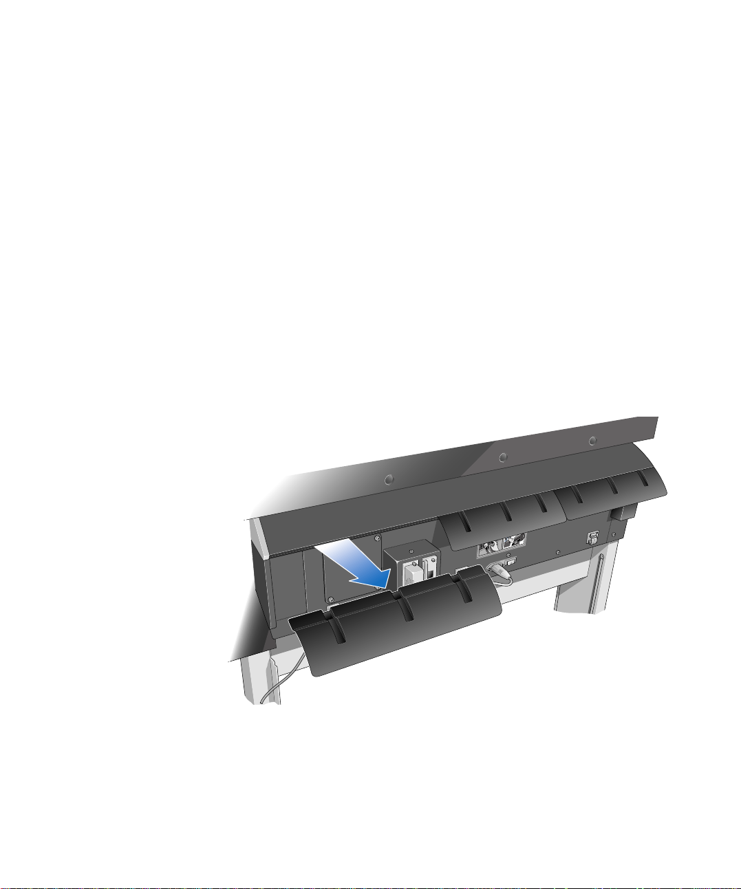
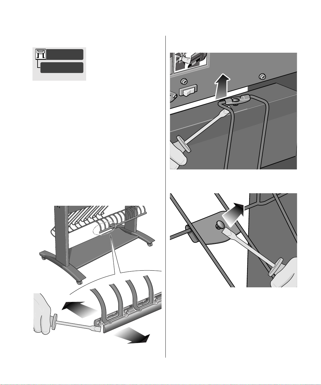
1 If the printer is turned on, turn it off at the front panel.
2 Looking at the rear of the printer, remove the paper path deflector from the left rear
side of the printer. To do this, push the two slots in the deflector downwards and
then pull it towards you.
2
1
5 HP DesignJet 1000 Series Take-Up Reel
Page 6
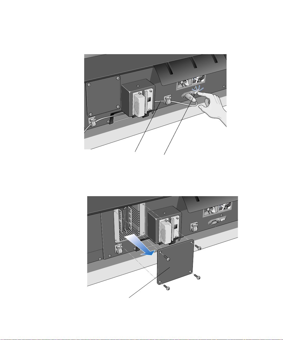
3 Switch the printe r off at th e power isolator switch at the back of the pr inter and
disconnect the power cord and the interface cable.
2
1
Power Cord
Power Off the Printer
4 Unscrew the four screws and remove the cover plate at the back of the printer.
To prevent loss of these screws, loo sely re-install them in the printer.
2
1
Cover Plate
HP DesignJet 1000 Series Take-Up Reel 6
Page 7
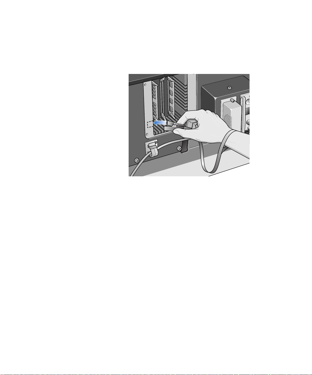
5 Looking at the back of the printer, you will see three slots. It is important to i nst all
the firmware module in the slot that is furthest to the right.
6 Put on a grounding wrist strap and attach the other end to the metal chassis of the
printer.
7 Remove the module that is currently occupying the rightmost slot. First push down
the lower locking tab to release the module, then pull out the module, holding it by
its edges.
8 Take the firmware module out of its bag. Hold the firmware module by its edges
with the non-metallic edges toward you.
7 HP DesignJet 1000 Series Take-Up Reel
Page 8
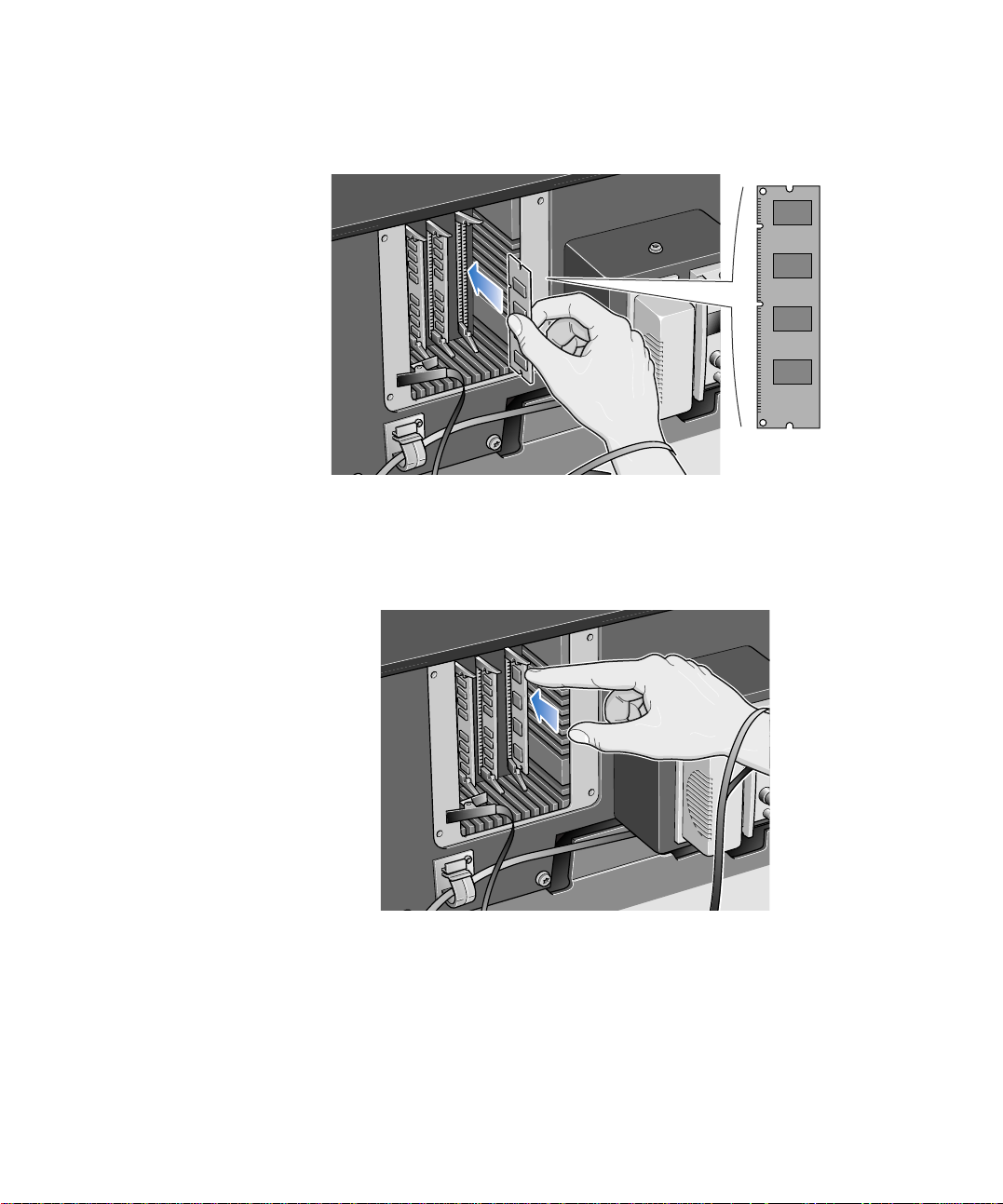
9 Carefully push the top e dg e of the firmware module into the slot.
10 Continue pushing the top edge of the firmware module until you feel it “click” into
position. At the same time you will see that the top locking tab locks into positio n.
HP DesignJet 1000 Series Take-Up Reel 8
Page 9
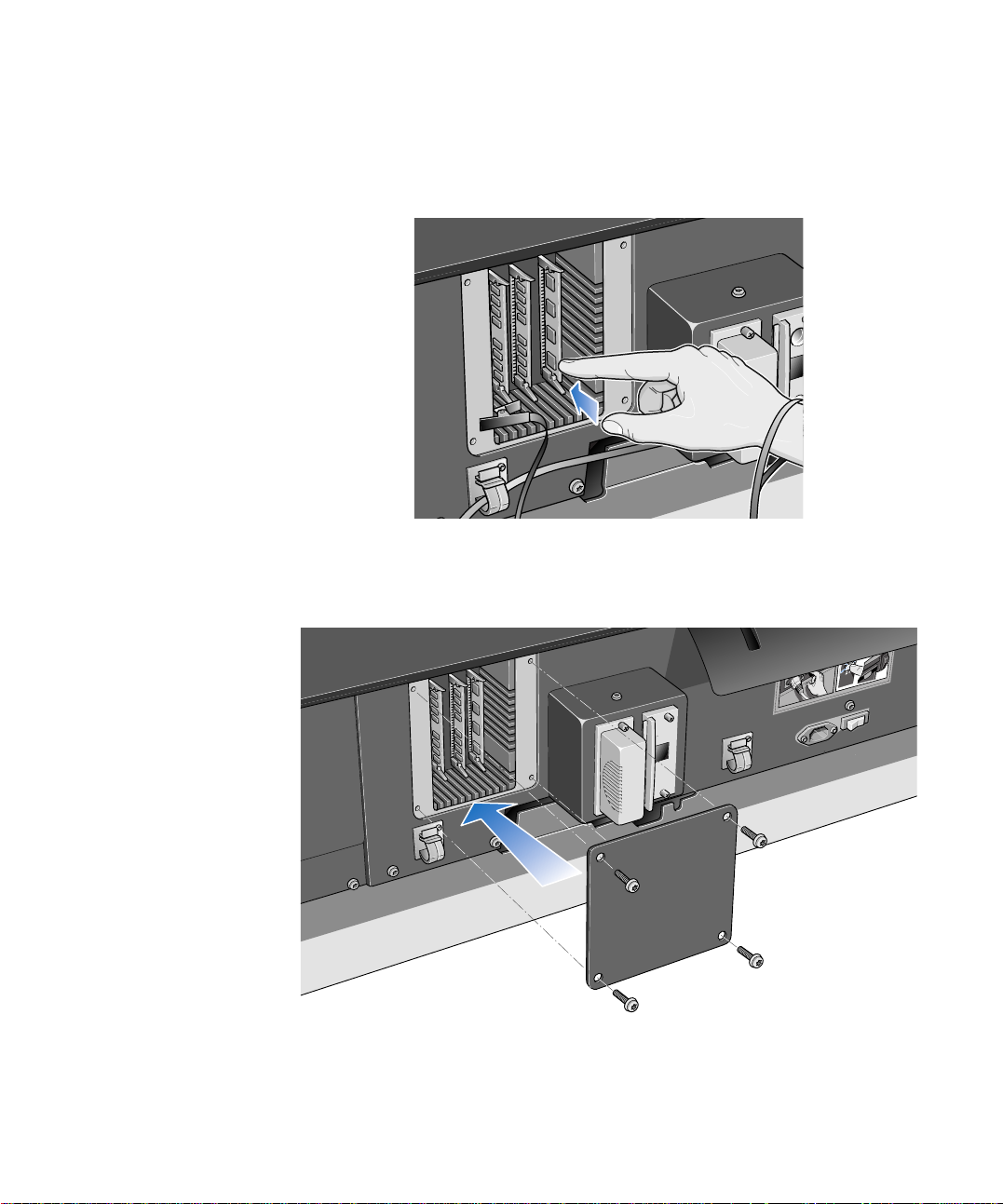
11 Carefully push the bottom edge of the firmware module in to the slot until you feel it
“click” into position. Again, you will see that the bottom locking tab locks into
position.
12 Remove the grounding wrist strap and then re-install the cover plate on the back of
the printer, using the four screws.
1
2
9 HP DesignJet 1000 Series Take-Up Reel
Page 10
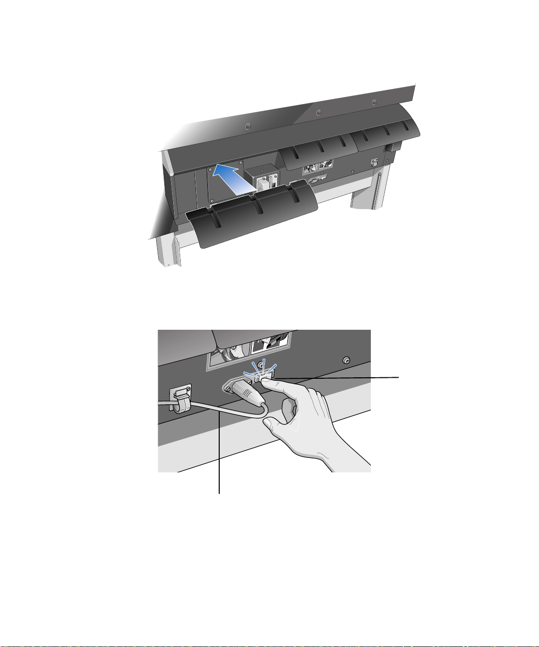
13 Re-install the paper path deflector on the left side of the printer.
2
1
14 Reconnect the power cord and the interface cable and switch on the power isolator
switch at the back of the printer.
1
Power Cord
You have now finished installing the firmware module.
HP DesignJet 1000 Series Take-Up Reel 10
Power Isolator Switch
Page 11
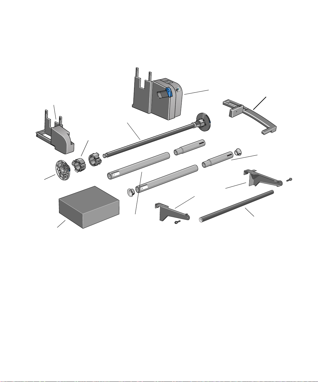
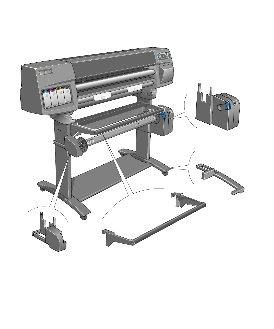
Take-Up Reel Components
These are the main components of the take-up reel.
Left-hand
assembly
Paper
guide
Documentation,
assembly tool, etc.
3-inch core
adaptors
Take-up reel
spindle
m
m
0
1
6
m
/
m
''
5
4
1
2
m
''/9
m
6
0
3
7
=
2
m
''/1
+
0
m
5
2
7
=
3
''/1
+
4
5
=
+
Take-up core
(different lengths)
Right-hand
assembly
m
m
3
0
2
'' /
8
8'' / 203mm
m
m
0
1
6
m
/
m
''
5
4
1
2
m
''/9
m
6
0
3
7
=
2
m
''/1
+
0
m
5
2
7
=
3
''/1
+
4
5
=
+
Deflector supports
Take-up reel
sensor
Paper weight
(different leng t h s )
Deflecto r rod
11 HP DesignJet 1000 Series Take-Up Reel
Page 12
The following picture shows the main components of the take-up reel and where
they are installed on the printer,
Right-hand
assembly
Take-up reel
sensor
Left-hand
assembly
HP DesignJet 1000 Series Take-Up Reel 12
Deflector
Page 13
Installing the Take-Up Reel
Device Setup
TUR installed
1. Using the front panel, select the Printer Setup
menu, then “Device Setup”, then “TUR installed”,
and change the value of this option from No to Yes.
If you do not find any “TUR installed” option, you
may need to upgrade your printer’s firmware (see
Upgrading your Printer, on page 4).
2. If a roll of paper is loaded, remove it (see
Chapter 3 of the User’s Guide).
3. If the bin cover is in use, remove it.
4. Remove the bin assembly with a flat-blade
screwdriver.
5. Carefully lev er apart t he cappi ng st rip assembly
through the holes at the bottom.
6. Carefully lever the six retaining clips from the
paper-bin support.
7. Carefully lever the six retaining clips from the
cross-brace assembly.
13 HP DesignJet 1000 Series Take-Up Reel
Page 14
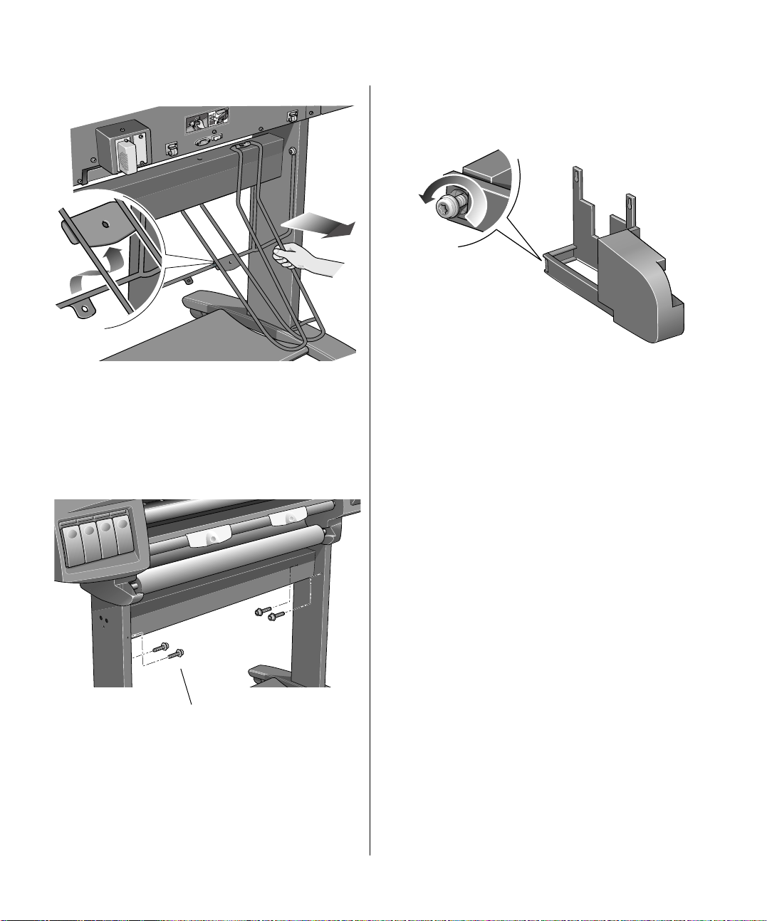
8. Remove the six paper-bin arms.
1
2
9. Remove the bin suppor t fr om the le gs assembly
by removing four screws. Do not use these
(shorter) screws for the next step.
10. Install the four (longer) screws from the take-
up reel kit loosely into the legs as shown below. Do
not tighten them yet.
11. Release the clamp on the left-hand assembly
by loosening the screw shown below. Do not remove
the screw.
Install 4
screws
HP DesignJet 1000 Series Take-Up Reel 14
Page 15

12. Open the clamp and fit the left-hand assembly
on to the screws installed in step 10.
14. Close the clamp and secure with the clamp
screw as shown below .
13. Pull the left-hand assemb ly dow n so that it
rests securely on the screws.
15. Tighten the two screws supporting the
assembly.
16. Release the clamp on the right-hand assembly.
by loosening the screw shown below. Do not remove
the screw.
15 HP DesignJet 1000 Series Take-Up Reel
Page 16

17. Open the clamp and fit the right-hand
assembly on to the screws installed in ste p 10.
18. Pull the right-hand assembly down so that it
rests securely on the screws.
19. Close the clamp and secure with the clamp
screw as shown below .
Clamp
Clamp screw
20. Tighten the two screws supporting the
assembly.
21. Unscrew the screw on the sensor assembly
shown below (but do not remove it) and open the
clamp.
HP DesignJet 1000 Series Take-Up Reel 16
Page 17

22. Install the front of the sensor assembly onto
the front of the right foot assembly as shown below
Sensor assembly
Right foot
assembly
23. Lower the sensor into the position shown
below.
24. Slide the sensor assembly hard up against the
leg and then close the sensor clamp as shown below.
25. Tighten the screw to secure the cl amp i n p la ce
and connect the sensor cable as shown below.
Ensure this is
clipped under
the foot
17 HP DesignJet 1000 Series Take-Up Reel
Page 18

26. Connect the power cord into the rear of the
take-up reel.
Power switch
27. Use the blue lever to unlock the left-hand
paper guide on the take-up reel spindle. Remove the
paper guide.
28. Assemble the take-up reel core and put i t on to
the spindle as shown below. Then put the paper
guide back on to the spi ndle an d lock it with t he blu e
lever..
A
29. Ensure the spindle lock is open.
30. Install the take-u p reel spindle into the printer
by pushing firmly on each end of the spindle A then
B as shown below.
m
m
5
0
3
/
''
2
1
m
m
7
6
0
m
m
'' / 1
5
1
2
9
4
'/
'
m
6
m
0
=
7
2
1
'/
+3
'
m
0
5
m
2
=
7
3
1
/
+
''
4
5
=
+
B
HP DesignJet 1000 Series Take-Up Reel 18
m
m
5
0
3
/
'
'
2
1
m
m
7
m
6
0
m
5
1
1
/
m
''
m
''/9
2
0
6
7
4
2
m
1
=
m
''/
2
0
7
+3
3
=
''/1
4
+5
=
+5
Page 19

31. IMPORTANT: Close the spindle lock.
12'' / 305mm
You must close the spindle lock, otherwise the takeup reel will not operate.
33. Slide each of the deflector supports sideways
until the T-piece on top of the support is fully
inserted into the gap between the cross brace and the
printer leg. The deflector support should now be
touching the take-up reel assembly.
32. A paper deflector, which consists of a rod and
two supports, is supplied with the take-up reel kit. Fit
the left and right supports on top of the printer’s
cross brace.
34. Rest the deflector rod on the two supports.
19 HP DesignJet 1000 Series Take-Up Reel
Page 20

35. Attach it to the su pports with the two screws
provided.
36. Turn on the t ake-up reel b y pressing t he switch
at the back.
37. If you have disconnected the printer’s power
cord, re-connect it now, turn on the power isolator
switch at the back of the printer, then turn on the
printer using the on/off button on the front panel.
38. Wait until the printer has finished initializing
and a “Ready” message is displayed on the front
panel.
You have now finished installing the take-up reel.
HP DesignJet 1000 Series Take-Up Reel 20
Page 21

Loading Paper on to the Take-Up Reel
Before using the take-up reel, ensure that it has been properly installed (see
preceding pages). In particular, the core tube should be mounted on the spindle.
CAUTION HP Bright White Inkjet Paper is available in 150-ft and 300-ft rolls. The take-
up reel can only completely roll up 150-ft rolls.
CAUTION Backlit paper with a separate slip sheet is not recommended for use with the
take-up reel.
■ If you already have a roll of paper in the printer, go to the front panel and select
the Roll Paper menu. Set the “TUR loaded” option to Yes. Now go to step 1
below.
■ If you do not already have a roll of paper i n the printer, load the roll according to
the instructions in Chap ter 3 of the User’s Guide. Soon after you have selected
the paper type, the front panel wil l off er the opt ion “Load Take-Up Reel (TUR)”,
which can be set to No or Yes. Select Yes. Continue with step 1 below.
1 The front panel will prompt you to move the paper using th e arrow keys. Use the ↓
key to move the leading edge of the paper down until it is level with the centre of
the core tube. Make sure the paper passes in front of the deflector, as shown below.
If you move the paper too far by mistake, use the ↑ key to move the paper back up.
21 HP DesignJet 1000 Series Take-Up Reel
Page 22

2 Ensure that the spindle lock is closed.
3 Move the adjustment levers on the left and right paper guides to the unlocked
position.
HP DesignJet 1000 Series Take-Up Reel 22
Page 23

4 The two paper guides and core must be positioned on the take-up reel spindle so
that the paper is in the center, between the paper guides. Adjust the position of the
core as shown below . The paper guide s may be slightly stif f on the spindle: you may
have to use both hands.
5 When you have adjusted the posi t ion of th e co re, p ull the adjustment levers on both
paper guides to the locked position.
23 HP DesignJet 1000 Series Take-Up Reel
Page 24

6 Pull the paper taut to the position shown below. Do not attempt to pull more paper
out of the printer; if you need more paper, use the front panel.
HP DesignJet 1000 Series Take-Up Reel 24
Page 25

7 Use a small amount of sticky tape to attach the paper to the core. Use three strips,
one in the middle (first) and then one at each side of the paper.
NOTE: Use only tape that will not tear the paper when it is removed later.
NOTE: To avoid the paper skewing as it is wound onto the core tube, ensure the
paper is straight when it is at tached.
8 Press the ↓ key on the front panel to advance the paper. Enough paper should be
advanced so that the paper can wrap at least once around the core.
Advance about this
much paper
25 HP DesignJet 1000 Series Take-Up Reel
Page 26

9Important: Press the paper wind button on the take-up reel panel indicated below
to wind the paper once around the core. If the paper fails to wind, ensure that the
spindle lock is closed (see step 2)
10 Press the ↓ button on the front panel to adv ance some more paper: enoug h to enable
you to insert the paper weight.
It is important that the paper weight is the same width a s the paper you are using.
By matching color coded lengths of plastic tube, you can make a paper weight for
different widths of standard paper sizes: 24”, 36”.
m
m
5
1
m
9
/
24'' / 610mm
''
m
6
0
7
2
=
1
m
''/
m
0
+3
2
7
=
3
1
''/
+5
4
=
+5
HP DesignJet 1000 Series Take-Up Reel 26
12'' / 305m
m
Page 27

11 Carefully insert the paper weight. Ensure that the end caps are installed and extend
42'' / 1067mm
+
54''/1372m
m
=
+
36''/915m
m
=
+
50''/1270m
m
=
42'' / 1067mm
+
54''/1372m
m
=
+
36''/915m
m
=
+
50''/1270m
m
=
over the edges of the paper.
CAUTION It is important that the paper weight is inserted. The take-up reel will not
function properly without it.
12'' / 305mm12'' / 305mm
12 Press Enter on the printer’s front panel, which will then display the Ready
message.
NOTE: When the take-up reel is in operation it is important to ensure that the take-
up reel sensor is not blocked.
27 HP DesignJet 1000 Series Take-Up Reel
Page 28

13 Shown below is how th e pr i nter sho uld look when it is in o per at io n. As paper is fed
from the printer it drops down in a loop and up into the take-up reel spindle.
Do not block the
take-up reel sensor
Make sure endcaps
are clear of paper
HP DesignJet 1000 Series Take-Up Reel 28
Page 29

Unloading Paper from the Take-Up Reel
To unload the roll paper from the take-up reel, perform the following procedure.
1 Ensure that the ink is dry. See Drying Time with the Take-Up Reel (page 36).
2 Press the FORM FEED AND CUT key on the front panel.
The front panel will prompt you t o re mov e th e paper weight and wind excess paper
using the take-up reel buttons.
3Important: Remove the paper weight as shown below. It may help you to remove
the end-caps first.
m
m
m
m
5
5
0
0
3
'' / 3
'' /
2
2
1
1
29 HP DesignJet 1000 Series Take-Up Reel
Page 30

4 Press the paper wind button shown below to wind the paper hanging do wn ont o t he
take-up reel.
5 Press Enter on the printer’s front panel. The printer will now cut the paper.
6 Slide open the spindle lock on the right-hand side of the take-up reel.
HP DesignJet 1000 Series Take-Up Reel 30
Page 31

7 Remove the take-up reel spindle.
m
m
5
0
'' / 3
2
1
m
m
5
1
m
/9
m
''
0
6
7
42'' / 1067mm
2
m
1
=
'/
m
'
2
0
7
+3
3
=
/1
''
4
+5
=
+5
8 Unlock and remove the left-hand paper guide from the take-up reel spindle.
Remove the core from the spindle.
Take-up reel spindle
Take-Up Core (with paper)
Paper
guide
To remove roll paper from the printer, see the User’s Guide.
31 HP DesignJet 1000 Series Take-Up Reel
Page 32

Changing the Core Tube on the Take-Up Reel
The core tube on the ta ke-up r eel must be the same width as the paper you are using .
To change the core, perform the following procedure.
1 Slide open the spindle lock on the right hand side of the take-up reel.
2 Remove the take-up reel spindle from the printer as shown by pulling firmly on
each end of the spindle, A then B.
HP DesignJet 1000 Series Take-Up Reel 32
m
m
5
0
3
/
'
'
2
1
m
m
7
m
6
0
m
1
5
1
/
m
9
''
/
m
'
'
2
0
6
7
4
2
m
1
=
/
'
m
'
2
0
7
+3
3
=
1
/
'
'
4
+5
=
+5
Page 33

3 Remove the left-hand paper guide.
4 Remove the old take-up core.
5 Install the new core you have chosen onto the spindle and re-install the left hand
guide assembly.
NOTE: You can also use an empty cardboard tube to replace the plastic t ake-up core
that was supplied with you r printer.
It is important tha t th e take-u p core i s the same widt h as the pape r you ar e usi ng. By
matching color coded lengths of plastic tube, you can make a take-up core for
different widths of standard paper sizes: 24”, 36”.
12'' / 305mm
m
24'' / 610m
+ 36''/915mm=
+ 50''/1270mm=
+ 54''/1372mm=
Alternatively, you can use an empty paper cardboard core.
NOTE: Ensure the take-up core is pushed firmly into both paper guides.
33 HP DesignJet 1000 Series Take-Up Reel
Page 34

NOTE: If you want to use a three-inch cardboard core, use the three-inch core
adaptors shown below.
Right-hand
paper guide
Take-up reel spindle
3-inch core adaptors
m
m
X
X
'' / X
X
X
XX'' / XXXXmm
36''/915mm=
+
50''/1270mm=
+
54''/1372mm=
+
Take-up core
Left-hand paper
guide
HP DesignJet 1000 Series Take-Up Reel 34
Page 35

6 Install the take-up reel spindle into the printer by pushing firmly on each end of the
spindle, A then B.
m
m
5
0
3
/
'
'
2
1
m
m
7
m
6
0
m
1
5
1
/
m
9
''
/
m
'
'
2
0
6
7
4
2
m
1
=
/
'
m
'
2
0
7
+3
3
=
1
/
'
'
4
+5
=
+5
7 Slide shut the spindle lock on the right-hand side of the take-up reel.
35 HP DesignJet 1000 Series Take-Up Reel
Page 36

Drying Time with the Take-Up Reel
If the ink is not dry when the paper is wound on to the take-up spindle, then the
image will be damaged.
In most cases the take-up reel paper loop gives the print time to dry before it is
wound on to the spindle. However, sometimes the print will need a longer time to
dry, and so the printer will slow down the printing process to allow more time
before winding on to the take-up reel; this is called the drying time.
Device Setup
Drying time
There are three drying time settings, whi ch are descri bed below. Y ou can change the
drying time setting by selecting the Printer Setup menu on the printe r’s front panel,
then “Device setup” and “Drying time”. T his is e xpl ai ned i n more d etail in Chapt er
2 of the User’s Guide.
Drying time=None
This setting means there is no delay to the printing process.
Hewlett-Packard has tested the HP paper range in different environmental
conditions. The table below shows paper that may need drying time and what
conditions are required to avoid it. This table applies to Best mode only.
HP Paper Type Width of
Printing Area
HP Glossy Photo 12 inches or more 50% 25°C
Matte Film 12 inches or more 45% 25°C
Clear Film 12 inches or more 75% 35°C
Maximum
Relative Humidity
Maximum
Temperature
HP DesignJet 1000 Series Take-Up Reel 36
Page 37

Drying time=Automatic
This is the default setting. If n e cessary, the printer will automatically adjust the
drying time depending on the following:
■ Type of paper
■ Print mode
■ Width of printing area
■ Environmental conditions
CAUTION To avoid the printer adding drying time to prints, operate the printer under the
following envir o nmental conditions. This table applies to Best mode only.
HP Paper Type Width of
Printing Area
HP Glossy Photo 12 inches or more 45% 25°C
Matte Film 12 inches or more 40% 25°C
Clear Film 12 inches or more 70% 35°C
Maximum
Relative Humidity
Maximum
Temperature
Drying time=Manual
In this mode you can override the amount of time that the printer has estimated to
print your image. However, the printer needs a certain minimum amount of time to
print. If the amount of time that you have specified is less than this, the printer will
ignore your setting.
37 HP DesignJet 1000 Series Take-Up Reel
Page 38

Troubleshooting
This page lists some possible explanations of problems that may occur with the
take-up reel.
Take-Up Reel Does Not Function
■ Perhaps you have a power problem. Check t hat the power cabl e is connected and
that there is power available at the socket.
■ Check that the ON/OFF sw itch is in the ON position at the back of the take-up
reel.
■ Check the spindle lever: it should be closed.
■ Check that the sensor cable from the right-hand assembly is connected correctly.
■ Check that the sensor operates correctly by placing a sheet of paper over the
sensor.
■ Perhaps you have a defective right-hand take-up reel assembly.
■ Perhaps you have a defective sensor assembly.
Paper Skewed on Take-Up Reel
■ Perhaps the paper was not loaded straight on the take-up reel core.
■ Perhaps the paper weight is not the same width as the paper.
■ Perhaps the take-up reel core is not the same width as the paper.
■ Perhaps the paper weight is not fully inserted.
■ Perhaps the take-up reel spindle is not installed correctly.
■ Perhaps the left- and right-hand take-up reel assemblies are not installed
correctly.
■ Ensure that there are no objects in the base tray assembly.
HP DesignJet 1000 Series Take-Up Reel 38
Page 39

Take-Up Reel Specifications
Paper Types
Plain Paper
HP Translucent Bond
HP Bright White Inkjet Paper (up to 150 feet/45 meters)
HP Vellum
HP Coated Paper
HP Heavy Coated Paper
HP High-Gloss Photo Paper
HP Matte Film
HP Clear Film
HP Natural Tracing Paper
Thin natural tracing paper (more than 70 g/m
Power Specifications
Source 100-240V ac ±10%. Autoranging.
Frequency 50-60 Hz
Current 0.2 amp maximum
Consumption 15 watts maximum
2
)
Environmental Specifications
Environmental
Operating Range
Storage ranges 95% humidity -40°C to 70°C (-40° F to 158° F)
Optimal print quality: 15°C to 30°C (59° F to 86° F)
Standard: 15°C to 35°C (59° F to 95° F)(except
glossy media: 15°C to 30°C (59° F to 86°
F)
Operating Relative Humidity: 20% to 80% Noncondensing
Printhead and Printhead Cleaners stored in the HP DesignJet Ink System Storage
Container:
T emp erature: +15°C to +35°C (+59° F to +95° F) @ 20% - 80% Relative Humidity
39 HP DesignJet 1000 Series Take-Up Reel
Page 40

EMC (ElectroMagnetic Compatibility) Specifications
Canada Canadian Department of Commu nications, Radio Interference R egulations
Class B compliant.
European Union 89/336/EEC EMC Directive compliant.
South Africa SABS licensed.
USA Federal Communications Commission.
Class B digital device.
CFR 47 Part 15
Australia
New Zealand
Taiwan (ROC) BCIQ Certified
Meets AS/NZS 3548
Safety Specifications
Constructed according to Information Technology Equipment (ITE) Safety Standard IEC950
Fixed,
Class I,
Plugable Type A,
Installation Category II,
Pollution Degree 2.
For use in indoor controlled office environments.
Canada Canadian Standards Association “Certified” ITE, CSA C22.2 No.950
European Union 73/23/EEC Low Voltage Directive compliant. Meets EN 60950
Germany TUV EN60950 certified
Mexico DGN, NOM019-SCFI-1994 certified
USA Underwriters' Laboratories
UL 1950 Listed
Poland PCBC certified
Russia GOST certified
HP DesignJet 1000 Series Take-Up Reel 40
Page 41

Regulatory Notices
Sound
Geräuschemission
(Germany)
LpA < 70 dB, am Arbeitsplatz, im Normalbetrieb, nach DIN 45635 T. 19.
Electro-Magnetic Compatibility (EMC)
FCC Statements
(U.S.A.)
CAUTION Pursuant to Part 15.21 of the FCC Rules, any changes or modifications to this
The U.S. Federal Communications Commission (in 47 cfr 15.105) has specified
that the following notices be brought to the attention of users of this product.
Product identification numbers:
Take-Up Reel C6079X (where X denotes any alphabetic character)
This device complies with part 15 of the FCC rules. Operation is subject to the
following two conditions: (1) This device ma y not cause harmful interference, and
(2) this device must accept any interference received, including interference that
may cause undesired operation.
equipment not expressly approved by the Hewlett-Packard Company, may
cause harmful interference and void the FCC authorization to operate this
equipment.
NOTE: This equipment has been tested and found to comply with the limits for a
Class B digital device, pursuant to part 15 of the FCC Rules. These limits are
designed to provide reasonable protection against harmful interference in a
residential installation. This equipment generates, uses and can ra diate radio
frequency energy and, if not installed and used in accordance with the instructions,
may cause harmful interference to radio communications. However, there is no
guarantee that interferen c e will not occur in a particular in stallation. If this
equipment does cause harmful interference to radio or television reception, which
can be determined by t urning the equipment of f and on, the user is encouraged to try
and correct the interferences by one or more of the following measures:
■ Reorient the receiving antenna
■ Increase the separation between the equipment and the receiver
■ Connect the equipment in to an outl et o n a ci rcuit different from th at t o whic h t he
receiver is connected
■ Consult the dealer or an experienced radio/TV technician for help
41 HP DesignJet 1000 Series Take-Up Reel
Page 42

The user may find useful the following booklet prepared by the FCC: “How to
Identify and Resolve Radio-TV Interference Problems”. This booklet is available
from the US Government Printing Office, Washington, DC 20402, Stock No. 004000-00345-4.
Normes de sécurité
(Canada)
DOC statement
(Canada)
Taiwanese EMI
statement
Address
Le présent appareil numérique n'émet pas de bruits radioélectriques dépassant les
limites applicables aux appareils numériques de Classe B prescrites dans le
réglement sur le brouillage radioélectrique édicté par le Ministére des
Communications du Canada.
This digital apparatus does not exceed the Class B limits for radio noise emissions
from digital apparatus set out in the Radio Interf erence Regulatio ns of the Canadian
Department of Communications.
Hewlett-Packard Company
Manager of Corporate Product Regulations
3000 Hanover Street
Palo Alto, CA 94304
415/857-1501
HP DesignJet 1000 Series Take-Up Reel 42
Page 43

Declaration of Conformity
DECLARATION OF CONFORMITY
according to ISO/IEC Guide 22 and EN 45014
Manufacturer’s Name:
Manufacturer’s Address:
Declares that the product
Product Name:
Model Number (s):
Product Accessory:
Conforms to the following Product Specifications:
Safety: IEC 950 (1991) + A1,A2,A3,A4 / EN 60950 (1992) + A1,A2,A3,A4
EMC: CISPR 22:1993 / EN 55022 (1994): Class B
Supplementary Information:
The product herewith complies with the requirements of the Low-Vo ltag e Directive 73/ 23/EEC and the EMC
Directive 89/336/EEC and carries the CE marking accordingly.
The product was tested in a typical system with a Hewlett-Packard DesignJet series printer.
Hewlett-Packard Espanola S.A.
Barcelona Division
Avda. Graells, 501
08190 Sant Cugat del Valles
Barcelona, Spain
HP Take Up Reel
HP C6079X (where X denotes any alphabetic character)
CSA C22.2 No 950 (1995)
UL 1950 (1995)
NOM-019-SCFI-1994
GB 4943 (1995)
IEC 825-1 (1993) / EN 60825-1 (1994) Class 1 for LED
EN 50082-1 (1992)
IEC 801-2:1991/prEN 55024-2 (1992): 4KV CD, 8KV AD
IEC 801-3:1984/prEN 55024-3 (1991): 3V/m
IEC 801-4:1988/prEN 55024-4 (1993): 1KV Power Lines
IEC 1000-3-2 (1995) / EN 61000-3-2 (1995);
IEC 1000-3-3 (1994) / EN 61000-3-3 (1995);
FCC Part 15 - Class B / DOC-B / BCIQ-A
AS/NZS 3548 / GB9254:1988
Sant Cugat del Valles (Barcelona),
10th of May 1999
European Contact: Your local Hewlett-Packard Sales and Service Office or Hewlett-Packard GmbH, Department HQ - TRE,
Herrenberger Strasse 130, D-71034 Boeblingen, Gernany (FAX: +49 7031 143143)
Josep-Maria Pujol,
Site Quality Services Manager
43 HP DesignJet 1000 Series Take-Up Reel
Page 44

© Copyright Hewlett-Packard Company 1999
Part number: C6079-90001
First edition
Printed in Europe
Hewlett-Packard Company
Barcelona Division
Avda. Graells, 501
08190 Sant Cugat del Vallès
Barcelona, Spain
 Loading...