

Page 1

HP Ultra/Wide SCSI 4 GB and
9 GB Hard Disk Drive
Installation Guide
HP Part Number 5967-4544
Printed in June 1998
Page 2

Notice
The information contained in this document is subject to change without notice.
Hewlett-Packard makes no warranty of any kind with regard to this
material, including, but not limited to, the implied warranties of
merchantability and fitness for a particular purpose. Hewlett-Packard shall not
be liable for errors contained herein or for incidental or consequential damages in
connection with the furnishing, performance, or use of this material.
Hewlett-Packard assumes no responsibility for the use or reliability of its software
on equipment that is not furnished by Hewlett-Packard.
This document contains proprietary information that is protected by copyright. All
rights are reserved. No part of this document may be photocopied, reproduced, or
translated to another la nguage without the prior written consent of HewlettPackard Company.
®
NetWare
Windows NT and NTAS® are registered trademarks of Microsoft Corporation.
SCO
Banyan
and UnixWare
®
UNIX® is a registered trademark of The Santa Cruz Operation, Inc.
®
and VINES® are the registered trademark of Banyan Systems
Incorporated. OS/2
Machines Corporation.
®
are registered trademarks of Novell, Inc. Microsoft
is the registered trademark of the International Business
®
Hewlett-Packard Company
Network Server Division
Technical Marketing/MS 49EU-FQ
5301 Stevens Creek Blvd.
P. O. Box 58059
Santa Clara, CA 95052-8059 USA
© Copyright 1998, Hewlett-Packard Company.
Audience A ssumptions
This guide is for the person who installs, administers, and troubleshoots LAN
servers. Hewlett-Packard Company assumes you are qualified in the servicing of
computer equipment and trained in recognizing hazards in products with
hazardous energy levels.
ii
Page 3

Contents
1 Prepare Drive for Installation.......................................................................... 1
Introduction........................................................................................................1
General Installation Steps ............................................................................. 1
Step 1: Prepare for Installation ..........................................................................2
Tools You Need............................................................................................. 2
Setup Information You Need......................................................................... 2
Unpack the Drive...........................................................................................3
Step 2: Determine the Drive Type ..................................................................... 3
Step 3: Set the SCSI Address ........................................................................... 8
Step 4: Connect SCSI Cable Adapter (if required) .......................................... 14
Step 5: Continue Installation............................................................................ 14
2 Mount the Drive in the NetServer L Series .................................................. 15
Step 1: Mount the Drive in the System ............................................................15
Step 2: Connect the Drive Activity Light........................................................... 16
Step 3: Connect the Drive................................................................................ 19
Step 4: Configure the Drive ............................................................................. 20
3 Mount the Drive in the NetServer E 45......................................................... 23
Step 1: Determine the Drive Location.............................................................. 23
Step 2: Mount the Drive in the System ............................................................25
Mount the Drive in Shelf 5 or 6....................................................................25
Mount the Drive in Shelf 3 or 4....................................................................26
Step 3: Connect the Drive................................................................................ 26
Step 4: Configure the Drive ............................................................................. 27
A Jumper Settings ............................................................................................ 29
Jumper Legend................................................................................................ 29
B Disk Drive Characteristics............................................................................ 31
NetWare and DOS........................................................................................... 31
OS/2 and Windows NT .................................................................................... 32
UNIX and Banyan Vines..................................................................................33
C Returning HP Hard Disk Drives.................................................................... 35
D Warranty and Support................................................................................... 37
Hardware Warranty.......................................................................................... 37
iii
Page 4

Contents
HP Repair and Telephone Support.................................................................. 37
E Regulatory Information................................................................................. 39
Index.................................................................................................................... 41
iv
Page 5
1 Prepare Drive for Installation
Introduction
This chapter describes the tools, setup information and the steps necessary to
install a SCSI hard disk drive into an HP NetServer. The drives do c umented in this
guide are listed in Table 1-1.
Table 1-1. Hard Disk Drive Product Numbers
HP Product Number
D4910A 4.26 GB
D4911A 9.10 GB
Capacity
1
General Installation Steps
In general, the steps for installing a hard drive are shown below. Please refer to the
detailed instructions in each step before attempting to install your drive.
1. Prepare for Installation
2. Determine the Drive Type
3. Set the SCSI Address
4. Connect SCSI Cable Adapter (if required)
5. Mount the Drive in the System
6. Connect the Drive Activity Light (if appropriate)
7. Connect the Drive
8. Configure the Dr ive
CAUTION In a few cases, drives with the same product number can be of
different types and require different jumper settings. If your
drive does not match the type in the figure, check the other
figures for the matching type.
1
The operating system may report a different capacity.
1
Page 6

Chapter 1 Prepare Drive for Installation
Step 1: Prepare for Installation
Gather the tools and the setup information you need to install the drive, before
removing the drive from its packaging.
Tools You Need
To install the disk drive, you need the following tools:
•
Tweezers, needle-nose pliers or a similar tool for setting configuration
jumpers.
•
A Torx
Setup Information You Need
Before you begin, you need the following setup info rmation:
•
The HP NetServer Installation Road Map for your system or Information
•
The SCSI addresses available in your system. (Refer to your system in
TM
T-15 screwdriver or a regular blade screwdriver.
Assistant on the HP NetServer Navigator CD-ROM.
Information Assistant on the HP NetServer Navigator CD-ROM for
information on determining available SCSI addresses.)
2
Page 7

Chapter 1 Prepare Drive for Installation
Unpack the Drive
CAUTION Shock: Hard disk drives are very susceptible to mechanical
shock and can be damaged by a drop as short as one-quarter of
an inch. Take care when unpacking and handling the disk
drive. If the drop would crack an egg, it will damage the drive.
Static: Protect the hard disk drive from static electricity by
leaving it in its anti-static bag until you are ready to install it.
Use an antistatic wrist strap and a grounding mat (3M
8501/8502/8505 or equivalent). If an antistatic work area is
not available, touch any unpainted metal surface to discharge
static electricity before handling the drive.
When you remove the hard disk drive from the anti-static bag,
handle it only by the frame. Do not touch the electrical
components. Place the drive on the anti-static bag whenever
you set it down.
After gathering the information and tools:
•
Remove the drive from the packaging.
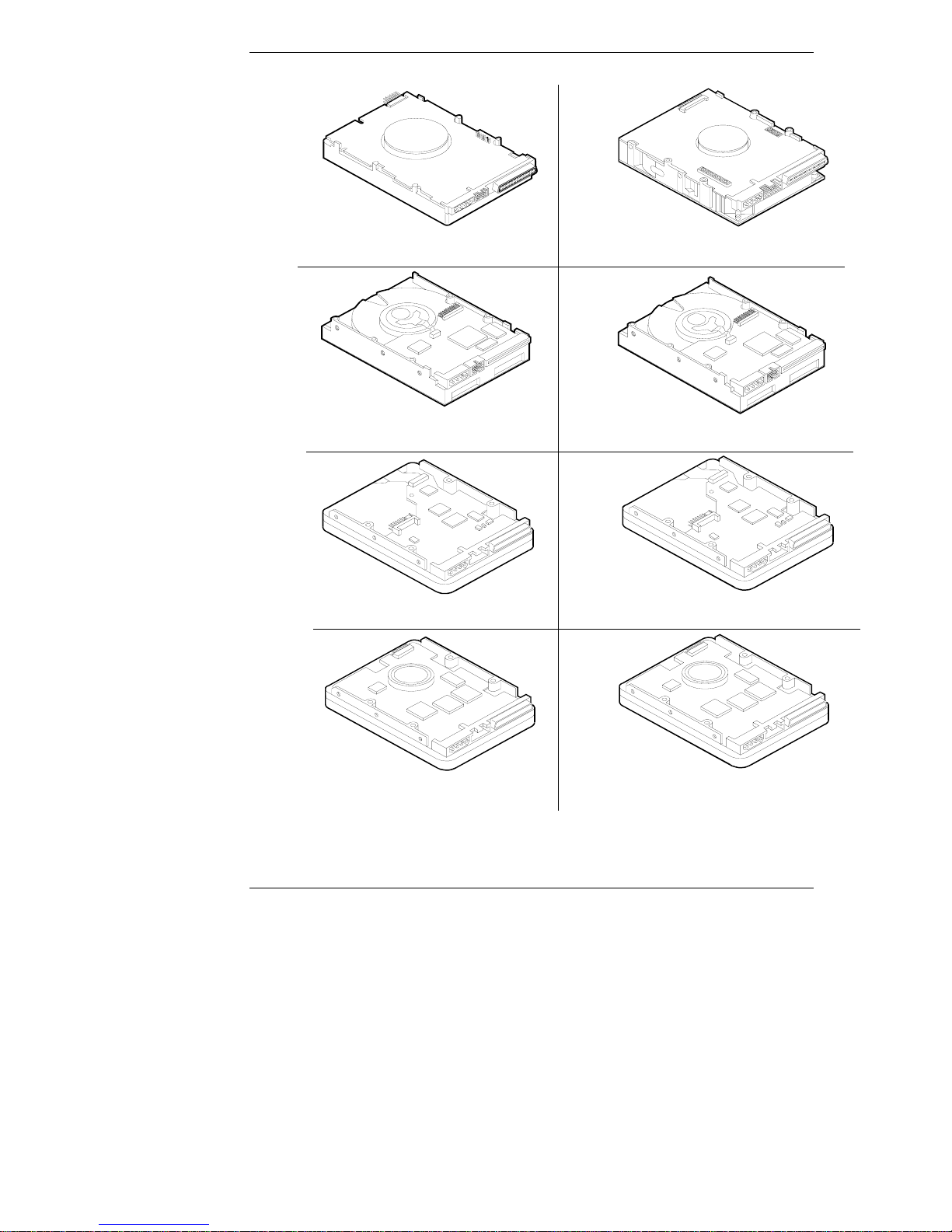
Step 2: Determine the Drive Ty pe
The type of the drive varies and drives with the same part number may be of
different types.
•
Match the drive you unpacked with the type of drive shown in Figure 1-1.
3
Page 8
Chapter 1 Prepare Drive for Installation
D4910A 4.26 GB Model
(T ype 1)
D4910A 4.26 GB Model
(Type 2)
D4910A 4.26 GB Model
(Type4)
D4911A 9.10 GB Model
(Type 3)
D4911A9.10 GB Model
(Type 2)
D4911A9.10 GB Model
(Type4)
4
D4910A 4.26 GB Model
(Type5)
D4911A9.10GBModel
(Type5)
Figure 1-1. Identification of the 4 Different Types of Drives
Page 9
Chapter 1 Prepare Drive for Installation
NOTE Some of the product numbers are duplicated, because the type
of drive shipped is not always the same. Therefore, it is
important that you match your drive to the correct type.
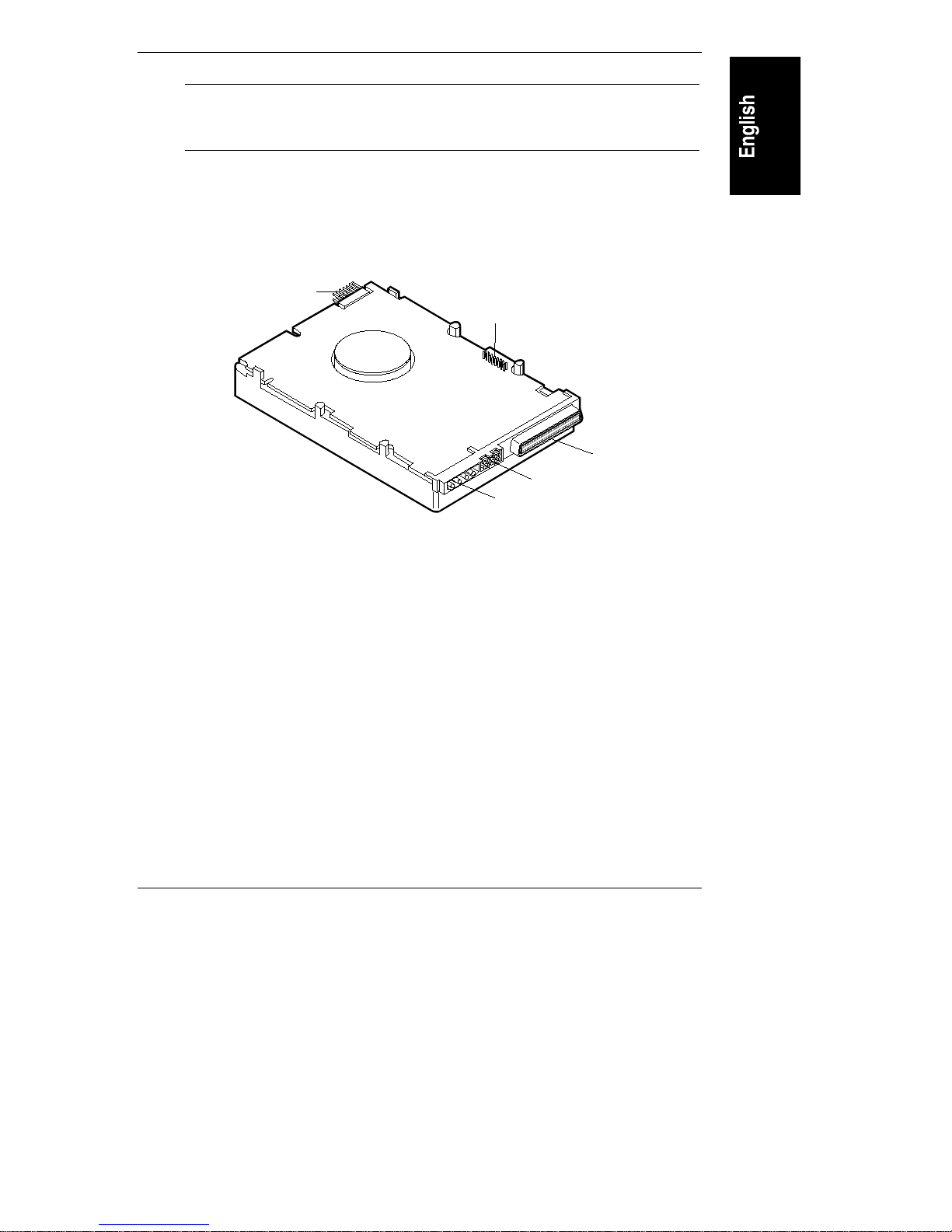
The types of drives differ in that the jumpers are in different locations. Refer to the
appropriate illustration (Figure 1-2, 1-3, 1-4, 1-5 o r 1-6) for your type of drive,
and note the location of the jumpers.
The "Disk Drive Characteristics" appendix shows a legend of the drive control
settings and the jumper control settings for the individual drives.
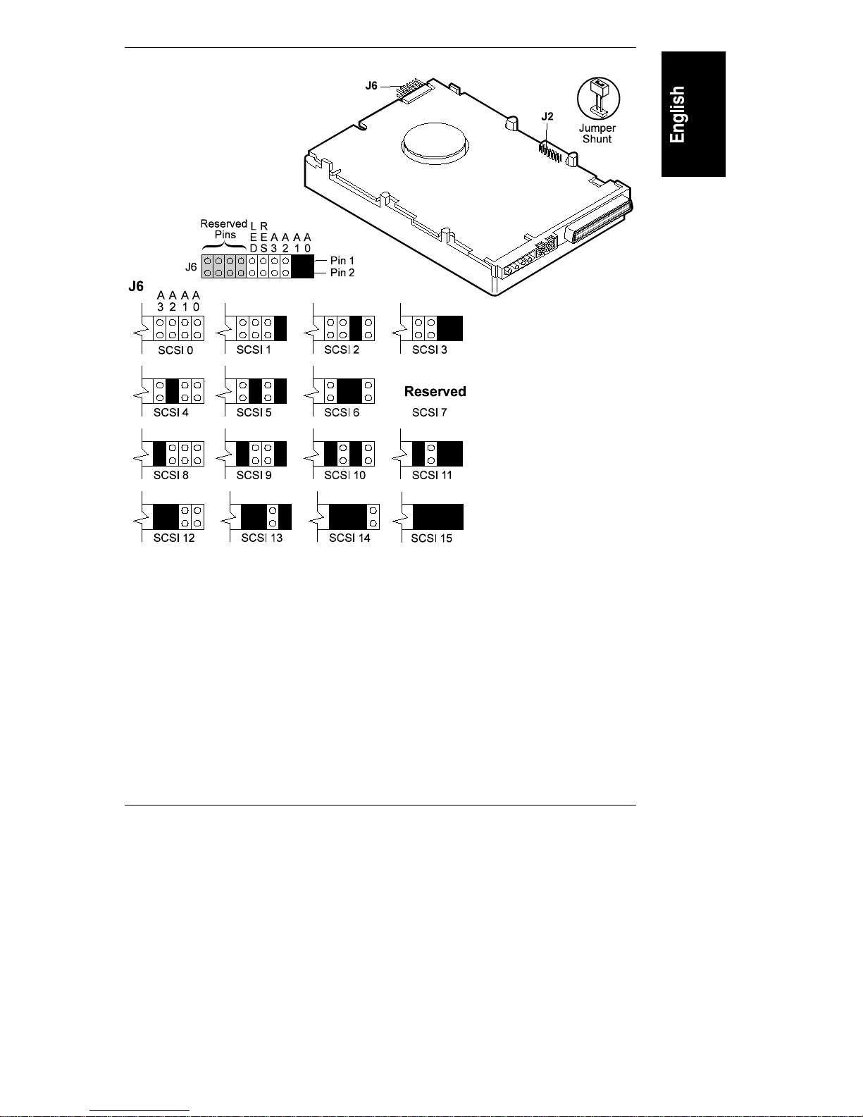
J6
J2
SCSI Connector
J1
Power Connector
Figure 1-2. Component Identification, Type 1 Drives
5
Page 10
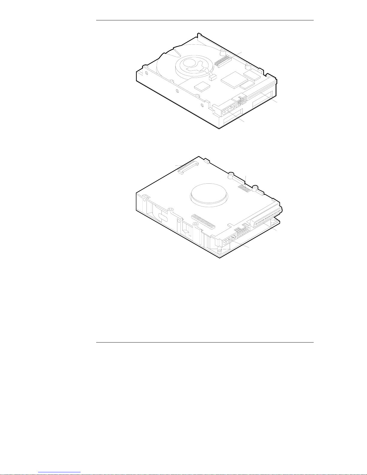
Chapter 1 Prepare Drive for Installation
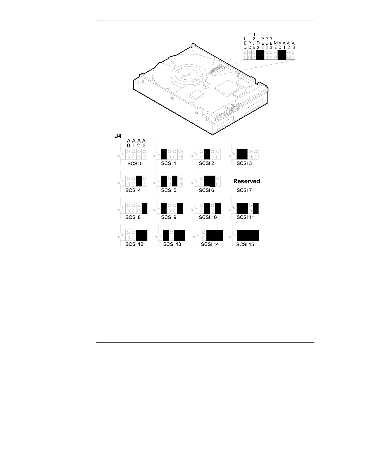
J4
SCSI
Connector
Power
Connector
Figure 1-3. Component Identification, Type 2 Drives
J6
J2
SCSI
Connector
Power Connector
Figure 1-4. Component Identification, Type 3 Drives
6
Page 11

Chapter 1 Prepare Drive for Installation
Figure 1-5. Component Identification, Type 4 Drives
Figure 1-6. Component Identification, Type 5 Drives
7
Page 12

Chapter 1 Prepare Drive for Installation
Step 3: Set the SCSI Address
The SCSI address is set using jumpers located on the drive. SCSI addresses range
from 0 to 15.
• Each drive is preset to SCSI address 3.
• Address 7 is reserved for communications with the SCSI host bus adapter.
• Addresses 8 to 15 should NOT be used because the HP NetServer will
time out waiting for the hard disk drive to spin up.
Set the drive to the lowest available SCSI address. Address 0 should be used for
the first drive in the system. Typically, address 1 is assigned to the second hard
disk drive, address 2 is assigned to the third drive, and so forth.
This step assumes the jumpers are accessible. If they are not accessible, it may be
necessary to remove the mounting tray or bracket to adjust the settings.
Each device on the channel needs a different SCSI address. If this is the first hard
drive in the system, complete this step to verify the jumper is set correctly. If this
is one of two or more SCSI devices in the system (and not the first drive), you
must change the SCSI address for the drive.
•
If you are connecting an Ultra/Wide SCSI drive to a narrow SCSI cable
and narrow SCSI controller, set the SCSI address to 0, 1, 2, or 3.
•
If you are connecting an Ultra/Wide SCSI drive to a wide SCSI cable and
wide SCSI controller, set the SCSI address to 0, 1, 2, 3, 4, 5, or 6.
Detailed descriptions of all the jumpers are provided in the "Jumper Settings"
appendix. Figures 1-7, 1-8, 1-9, 1-10 and 1-11 show the default SCSI address
settings for each drive.
8
Page 13
Chapter 1 Prepare Drive for Installation
Figure 1-7. SCSI Address Settings, Type 1 Drives
9
Page 14
Chapter 1 Prepare Drive for Installation
10
Figure 1-8. SCSI Address Settings, Type 2 Drives
Page 15

Chapter 1 Prepare Drive for Installation
Figure 1-9. SCSI Address Settings, Type 3 Drives
11
Page 16

Chapter 1 Prepare Drive for Installation
12
Figure 1-10. SCSI Address Settings, Type 4 Drives
Page 17

Chapter 1 Prepare Drive for Installation
Figure 1-11. SCSI Address Settings, Type 5 Drives
13
Page 18

Chapter 1 Prepare Drive for Installation
Step 4: Connect SCSI Cable Adapter (if required)
The SCSI cable adapter (see Figure 1-11) allows you to connect an Ultra/Wide
SCSI drive to a narrow SCSI cable and narrow SCSI controller. If you are not
connecting your drive to a narrow cable, continue with Step 5.
Figure 1-12. Narrow to Ultra/Wide SCSI Adapter
•
Plug the narrow SCSI cable into the adapter, aligning the notch in the
connector with the slot in the adapter.
•
Plug the other end of the adapter into the drive. The shape of the connector
prevents it from being plugged into the drive incor rectly.
Step 5: Continue Installation
If you are installing the drive in an HP NetServer L Series, continue with
Chapter 2. If you are installing the drive in an HP NetServer E 45, continue with
Chapter 3.
14
Page 19

2 Mount the Drive in the NetServer
L Series
This chapter describes the installation of a drive in the NetServer L Series.
Step 1: Mount the Drive in the Sy stem
Determine what type of mounting tray or bracket is correct for the system.
Use the tray with the drive activity light for mounting a drive in the front of a
NetServer. The drives are shipped already mounted on this tray. To purchase the
tray separately, order Product Number D2198B (multipack).
Front view
Figure 2-1. Tray
Consult Information Assistant on the HP NetServer Navigator CD-ROM for your
system for additional information regarding the tray or bracket.
Attach a tray to a drive or change a factory-supplied tray (if needed) as follows:
•
Place the drive on a flat surface, free of static electricity, with the circuit
board of the drive facing up.
•
If your drive is on a tray that is not appropriate for your server, remove the
four screws attaching the drive to the tray and remove the tray. These
screws can be used to mount the drive on the tray or bracket.
•
Place the new tray or bracket on the drive.
15
Page 20

Chapter 2 Mount the Drive in the NetServer L Series
•
Align the mounting holes on the tray or bracket with those on the drive.
•
Attach the tray or bracket to the drive using the four screws.
Step 2: Connect the Drive A ctivity Light
The mounting tray (D2198B) has a drive activity light on the front-panel. The
drive activity light flashes during data access and the drive power-on self-test.
Connect the drive activity light for your drive as shown in Figures 2-2, 2-3, 2-4, 25, and 2-6.
16
Figure 2-2. Activity Light Connection, Type 1 Drives
Page 21

Chapter 2 Mount the Drive in the NetServer L Series
Figure 2-3. Activity Light Connection, Type 2 Drives
Figure 2-4. Activity Light Connection, Type 3 Drives
17
Page 22

Chapter 2 Mount the Drive in the NetServer L Series
A0A1A2A
J3
Pin 1
Pin 2
+5VRedCable
Black Cable
Drive ActivityLED
R
L
E
E
DME
3
S
R
R
E
E
S
S
Figure 2-5. Activity Light Connection, Type 4 Drives
A0A1A2A
J3
Pin 1
Pin 2
+5V Red Cable
Black Cable
R
L
E
E
DME
3
S
R
R
E
E
S
S
18
Drive ActivityLED
Figure 2-6. Activity Light Connection, Type 5 Drives
Page 23

Chapter 2 Mount the Drive in the NetServer L Series
Step 3: Connect the Drive
In this step, you install the drive in the system, and connect the SCSI data cable
and the drive power cable. The SCSI cable is connected to the SCSI connector on
the system board or to a SCSI host bus adapter board.
The correct cable for HP Ultra SCSI-3 drives has an active termination module on
one end of the cable. The active termination module is easy to recognize, because
it looks different from the other connectors on the cable, and the word "active"
should appear on the active termination module.
NOTE HP SCSI-3 drives must connect to the actively terminated
cable. Using an incorrect cable (or not using an active
termination module) will cause data transmission errors.
Do not use passively terminated cables with Ultra SCSI-3 hard
disk drives.
CAUTION The active termination module belongs on the last connector
on the cable, opposite the system board or host bus SCSI
adapter. Do not remove this module.
•
Turn off your system and the display.
•
Disconnect the power cords.
•
Detach any external cables.
•
Remove the cover from the HP NetServer.
•
Remove any hardware necessary to reach the cables or insert the drive.
Consult Information Assistant on the HP NetServer Navigator
CD-ROM for your system for instructions.
•
Insert the mounted hard dr ive in your HP NetServer.
•
Connect the internal power supply cable to the hard disk drive with one of
the unused cables fro m the power supply unit.
•
Select an available connector on the SCSI cable and connect it to the disk
drive.
19
Page 24

Chapter 2 Mount the Drive in the NetServer L Series
CAUTION The connector is keyed. Do not force the connector in the slot.
(The red stripe on the edge of the cable denotes the positio n of
Pin 1 on the cable.)
•
Record information about the new hard disk setup, including: model
number, capacity, and SCSI address.
•
Reassemble your HP NetServer.
•
Connect all the cables and power cords.
•
Power up your HP NetSe rver.
NOTE If a drive recognition error displays during system startup, press
Ctrl+Alt+Del to restart the system. Do not power cycle the
system because the drive recognition error will likely repeat.
Step 4: Configure the Drive
The SCSI controller is configured for the drive using a configuration utility.
20
•
If the SCSI controller is not yet configured, run the appropriate
configuration utility, included with your system.
•
Consult your operating system documentation for information on
formatting the disk drive for use in the system. Typically, you create one or
more partitions on your new hard drive, using the guidelines in Appendix
B, "Disk Drive Characteristics."
•
Initialize the file system, using the operating system format utility.
CAUTION No low-level format is needed. HP performs the low-level
format at the factory.
NOTE If you are experiencing problems with the drive, watch the
messages on your monitor while the system boots. A message
appears if a drive is not recognized by the HP NetServer (which
happens when the HP NetServer attempts to communicate with
a drive before the drive has finished spinning up).
If the system did not recognize a hard drive:
Page 25

Chapter 2 Mount the Drive in the NetServer L Series
• Wait until all drives reach full speed.
• Press the Reset button on the system or press the
Ctrl+Alt+Del hot-key combination to restart the HP
NetServer without powering it down.
Do not power-down (power-cycle) the system to restart it, as
this causes all the drives to stop spinning.
21
Page 26

Page 27

3 Mount the Drive in the NetServer
E 45
This chapter provides instructions for installing a hard disk d rive in the HP
NetServer E 45.
Consider the following when installing a drive in an HP NetServer E Series
system.
• The HP NetServer E 45 supports up to four 4 GB or four
9 GB drives.
• Drive types D4910A and D4911A are supported in the HP
NetServer E 45.
• Drive types D4910A and D4911A are not supported in the HP NetServer E
40 or the HP NetServer E 30.
NOTE The HP NetServer E 45 ships with drive mounting trays
installed in shelves 3 and 4. Drives shipped as accessories
usually come installed on a factory tray, which must be
removed. The drive must be put on an NetServer E 45 tray.
Step 1: Determine the Drive Location
The drive can be mounted in one of several possible locations in the system. If you
decide to mount the drive on shelf 5 or 6 (recommended), you will fasten the drive
to the chassis. If you decide to install the drive on shelf 3 or 4, you will mount the
drive onto a tray, which is installed in one of the shelves.
•
Decide whether to mount the drive on shelf 5 or 6 (recommended) or on
shelf 3 or 4. See Figure 3-1 for the locations of shelves in the system, and
some of the cabling options.
23
Page 28

Chapter 3 Mount the Drive in the NetServer E 45
Power
Switch
FlexibleDisk
Controller
FlexibleDisk
CD-ROM
SystemBoard
IDE1
IDE2
F5
D5
Shelf 1
Shelf 2
Shelf 3
Shelf 4
For cabling options and connector locations, see the
Technical Reference Label inside your HP NetServer chassis.
*
C33
SCSI Card
PCI 1
Shelf 5
Shelf 6
Key
AvailableConnector
EngagedConnector
50-pinSCSI Cable
C33
D5
IDE CD-ROM Cable
FlexibleDisk Cable
F5
Built-inSCSI Terminator
*
Figure 3-1. NetServer E 45 Shelf Positions and Cabling Options
•
Use the guidelines in Table 3-1 to determine the proper location within
your HP NetServer E 45 to install your hard disk drive.
Table 3-1. Mass Storage Device Locations and SCSI ID Settings
Device Location SCSI Address
Standard Hard Drive
Shelf 5 0 (default)
(in models that include
one)
24
HP Accessory 4 GB
HD (D4910A)
Shelf 3, 4, 5 or 6 0, if it is the first hard drive; for
subsequent drives, use address 1, 2
or 3
HP Accessory 9 GB
HD (D4911A)
Shelf 3, 4, 5 or 6 0, if it is the first hard drive; for
subsequent drives, use address 1, 2
or 3
HP SureStore T4i Shelf 3 or 4 4 (default)
HP SureStore 8i,
5000i, 2000i
Standard SCSI
Shelf 3 or 4 2 (default)
(can be set to any unused address)
PCI 1 Slot 7
Controller
Page 29

Chapter 3 Mount the Drive in the NetServer E 45
•
If the drive is in a factory-provided tray, place the drive on a flat surface
free from static electricity with the circuit board on the drive facing up.
Remove the four screws that attach the drive to the tray and remove the
drive. (These screws can be used to mount the drive in the HP NetServer E
45.)
Step 2: Mount the Drive in the Sy stem
To prepare to install the drive:
•
Turn off your system and the display.
•
Disconnect the power cords.
•
Detach any external cables.
•
Remove the cover from the HP NetServer.
•
Remove any hardware necessary to reach the cables or insert the drive.
Consult Information Assistant on the HP NetServer Navigator CD-ROM
for your system for specific instructions for removing components.
If you are mounting the drive in shelf 5 or 6, continue with "Mount the Drive in
Shelf 5 or 6" If you are mounting the drive in shelf 3 or 4, continue with "Mount
the Drive in Shelf 3 or 4."
Mount the Drive in Shelf 5 or 6
•
Remove the rear cooling fan.
•
Align the four screw holes of the rear shelf with the four screw holes of the
drive.
•
Loosely install all of the screws (provided with the drive), then tighten the
screws to no more than eight inch-po unds (0.9 newton meters).
•
Carefully insert the fan wire fully into the drive bay.
•
Replace the rear cooling fan.
Continue with Step 3.
25
Page 30

Chapter 3 Mount the Drive in the NetServer E 45
Mount the Drive in Shelf 3 or 4
•
Remove the drive mounting tray from the system. (See Figure 3-2.)
Figure 3-2. Hard Disk Drive Mounting Tray
•
Align the four screw holes in the bottom of the NetServer E 45 tray with
the four screw holes in the bottom of the drive.
•
Loosely install all of the screws, then tighten the screws to no more than
eight inch-pounds (0.9 newton-meter).
•
Place the tray in the shelf opening and slide the tray into the shelf.
•
Align the screw holes at the front of the tray with the holes in the front of
the chassis.
•
Loosely install all screws, then tighten each screw to no more than eight
inch-pounds (0.9 newton-meter).
Step 3: Connect the Drive
Connect the SCSI data cable and power cable and complete the drive installation.
The SCSI cable is connected to the SCSI connector on the SCSI host bus adapter
board.
The correct cable for HP Ultra SCSI-3 drives has an active termination module on
one end of the cable. The active termination module is easy to recognize, because
it looks different from the other connectors on the cable. The cable bundled with
your system is actively terminated.
26
Page 31

Chapter 3 Mount the Drive in the NetServer E 45
NOTE HP SCSI-3 drives must connect to the actively terminated
cable. Using an incorrect cable (or not using an active
termination module) will cause data transmission errors. Do not
use passively terminated cables with Ultra SCSI-3 hard disk
drives.
CAUTION The active termination module belongs on the last connector
on the cable. Do not remove this terminator.
•
Connect the internal power supply cable to the hard disk drive with one of
the unused cables fro m the power supply unit.
•
Select an available connector on the SCSI cable and connect it to the disk
drive.
CAUTION The connector is keyed. Do not force the connector in the slot.
(The red stripe on the edge of the cable denotes the positio n of
Pin 1 on the cable.)
•
Record information about the new hard disk setup, including: model
number, capacity, and SCSI.
•
Reassemble the HP NetServer.
•
Connect all the cables and power cords.
•
Turn on power to the HP NetServer.
Step 4: Configure the Drive
Configure the SCSI controller for the drive using the SCSI SelectTM utility.
•
If the SCSI controller is not yet configured, run the SCSI Select utility,
included with your system.
•
Consult your operating system documentation for information on how best
to format the disk drive for this HP NetServer. Typically, you create one or
more partitions on your new hard drive, using the guidelines in Appendix
B, "Disk Drive Characteristics."
27
Page 32

Chapter 3 Mount the Drive in the NetServer E 45
CAUTION No low level format is needed. HP performs the low-level
format at the factory.
•
Initialize the file system, using the operating system format utility.
NOTE If you are experiencing problems with the drive, watch the
messages on your monitor while the system boots. A message
appears if a drive is not recognized by the HP NetServer (which
happens when the HP NetServer attempts to communicate with
a drive before the drive has finished spinning up).
If the system did not recognize a hard drive:
• Wait until all drives reach full speed.
• Press the Reset button on the system or press the
Ctrl+Alt+Del hot-key combination to restart the HP
NetServer without powering it down.
Do not power-down (power-cycle) the system to restart it, as
this causes all the drives to stop spinning.
28
Page 33

A Jumper Settings
Each of the drives has an Ultra SCSI-3, single-ended, wide 8 or 16-bit interface
data connection. The hard disk drives are shipped without SCSI terminators. These
drives are ready to use on a SCSI cable with a built-in active terminator.
The terminator power options are:
1. No terminator power is connected to drive terminators or the SCSI bus I/O
pin 26 (recommended).
2. Drive supplies own terminator power only.
3. Drive supplies power to I/O pin 26 of the SCSI bus: no power is supplied
to the internal terminators.
4. Drive supplies terminator power to itself (internal connection) and to I/O
pin 26 of the SCSI bus.
5. Connects terminator power from the SCSI bus I/O pin 26 to the drive’s
internal terminator, if present.
Each hard disk drive is configured at the factory for optimum performance on
most systems. With the possible exception of setting the SCSI address, you should
not change default settings. Cha nging the disk drive configuration can cause
unexpected or undesirable results.
Jumper Legend
Table A-1 shows the jumper descriptions for all drives. All jumper controlled
features are not available on all drives. (An * indicates a factory default setting.)
Table A-1. General Jumper Description
ID Description
Ax SCSI Addresses (A0, A1, A2 and A3)
See the "Set the SCSI Address" step in the chapter "Prepare
Drive for Installation" for detailed information.
LED Light Emitting Diode Drive Activity Light
Not a jumper in the traditional sense. This is where the drive
activity light connects to the drive.
29
Page 34

Appendix A Jumper Settings
ID Description
DS Delay Spin-Up
On* Motor start up is delayed by the sum of the SCSI ID times 6
seconds after power is applied; i.e., Drive 0 spindle starts
immediately, drive 1 starts after a 6 second delay, drive 2 starts
after a 12 second delay, and so forth.
Off Motor start up begins immediately after system power up,
unless Motor Start Enable is on. If Motor Start Enable is on, it
overrides this setting.
ME Motor Start Enable
On Drive spindle starts when the Start Unit command is received
from the host system. If the Delay Spin-Up feature is on, the
Delay Spin-Up feature is overridden.
Off* Spindle starts immediately after power up. If Delay Spin-Up is
on, it overrides this setting.
PD Parity Disable
On Parity checking and parity error reporting by the drive is
disabled.
RES Reserved
WP Write Protect
12/6 Delay Time
* Defa ult
NOTE Jumpers are "off," when the jumper is not installed (no
30
Off* Parity checking and parity error reporting by the drive is
enabled. The drive checks for parity and reports the results of
parity checking to the host system.
This pin set is not used and must remain as set at the factory.
On The drive is write protected.
Off* The drive is not write protected.
On The delay spin-up is 12 seconds.
Off* The delay spin-up is 6 seconds.
electrical connection) or "on," when the jumper is in place
(completing the electrical connection).
Page 35

B Disk Drive Characteristics
The proper settings for the following items depend on the operating system
(NetWare, DOS, OS/2, Windows NT, UNIX or Banyan Vines) and corresponding
version number:
• Extended Translation setting for the controller
• Partitions, logical drives or divisions for the ho t swap hard disk drive
For non-UNIX systems, partition and logical hot swap hard disk drive sizes also
depend on:
• Partition type (Bootable or Non-bootable)
• File system (FAT, HPFS or NTFS)
To determine the appropriate controller and d isk d rive configuration, consult the
section below for your operating system.
NetWare and DOS
Table B-1. Partitioning Information for NetWare and DOS
Extended
Primary
(Boot)
Partition
1 GB max. for
DOS
Extended
Partition
None N/A
Operating
System
NetWare
with DOS
Disk Use
Operating
system
and data
Translation
for > 1 GB
Drive
Disabled 30-50 MB rec.,
Logical
disk
NetWare
only
DOS only Operating
DOS only Data only Enabled None Disk
Data only Disabled None None N/A
Enabled 2 GB max. Rest of disk 2 GB
system
capacity
max.
2 GB
max.
31
Page 36

Appendix B Disk Drive Characteristics
OS/2 and Windows NT
NOTE Configure the controller with "Extended Translation for Drives
> 1 GB" enabled.
Table B-2. Partitioning Information for OS/2 and Windows NT
Maximum
Bootable Partition
Operating
System
OS/2 2.x 2 GB N/A 2 GB 2 GB N/A
OS/2 Warp
Family
Windows
NT 3.1
Windows
NT 3.5
Windows
NT 3.51
Windows
NT 4.0
Windows
NT 3.5.1
FAT or
HPFS
2 GB N/A 2 GB 64 GB N/A
2 GB 2 GB 2 GB Disk
2 GB 2 GB 2 GB Disk
4 GB 4 GB 4 GB Disk
4 GB 4 GB 4 GB N/A Disk
4 GB 4 GB 4 GB Disk
NTFS FAT HPFS NTFS
Maximum
Non-bootable Drive
Disk
capacity
capacity
capacity
capacity
capacity
Disk
capacity
Disk
capacity
capacity
Disk
capacity
32
Page 37

Appendix B Disk Drive Characteristics
UNIX and Banyan Vines
Table B-3. Partitioning Information for UNIX
Maximum Size Maximum Number
Extended
File
System
(Division)
1 GB (root)
2 GB
(data)
Partitions
on Disk
47
Divisions in
Partition
Operating
System
SCO UNIX
3.2.4.2 and
ODT/OS 3.0
Translation
for > 1 GB
Drive
Disabled Disk
Partition
capacity
SCO UNIX
3.2v5.0 and
OS 5.0
UnixWare
1.1
UnixWare
2.0.X Disabled
UnixWare
2.1.X Disabled
Banyan
VINES 5.54,
6X and 7.X Disabled
SCO Open
Server 5.0 Disabled
Disabled Disk
Disabled Disk
capacity
capacity
Disk
capacity
Disk
capacity
Disk
capacity
Disk
capacity
1 TB 4 7
2 GB 4 16 slices
2 GB–1 TB 4 16 slices
2 GB–1 TB 4 184 slices
2 GB 1 N/A
1 TB 4 7
33
Page 38

Page 39

C Returning HP Hard Disk Drives
When returning a drive for service, repair, or replacement, use the packaging
supplied with the exchange drive.
Foam
Antistatic Bag
Hard Disk Drive
Figure C-1. Drive Repackaging
35
Page 40

Page 41

D Warranty and Support
The hardware warranty below applies to components purchased as accessories. If
your component was factory installed as part of an HP NetServer model, refer to
the warranty statement provided with your system documentation.
Hardware Warranty
This HP NetServer accessory is covered by a limited hardware warranty for a
period of one year from receipt by the original end-user purchaser.
Once installed in an HP NetServer, this accessory may carry the longer of either a
one-year warranty or the remainder of the warranty period for the HP NetServer in
which it is installed.
This accessory may be serviced through expedited part shipment. In this event, HP
will prepay shipping charges, duty, and taxes; provide telephone assistance on
replacement of the component; and pay shipping charges, duty, and taxes for any
part that HP asks to be returned.
The customer may be required to run HP-supplied configuration and diagnostic
programs before a replacement will be dispatched or an on-site visit is authorized.
Refer to the warranty statement provided with your original HP NetServer system
documentation for the warranty limitations, customer responsibilities, and other
terms and conditions.
HP Repair and Telephone Support
Refer to the Service and Support section of your HP NetServer system
documentation for instructions on how to obtain HP repair and telephone support.
37
Page 42

Page 43

E Regulatory Information
DECLARATION OF CONFORMITY
according to ISO/IEC Guide 22 and EN 45014
Manufacturer’s Name: Hewlett-Packard Company
Address: 5301 Stevens Creek Blvd.
Santa Clara, CA 95052
USA
declares, that the product
Product Name: 4 GB and 9 GB Ultra SCSI-3 Disk Drives
Model Number(s): HP D4910A and HP D4911A
Product Options: N/A
conforms to the following Product Specifications:
Safety: IEC 950:1991 + A1, A2 / EN 60950 (1992) + A1, A2
EMC: CISPR 22:1985 / EN 55022 (1988) - Class B
EN 50082-1:1992 - Generic Immunity
IEC 801-2:1991, 4 kV CD, 8 kV AD
IEC 801-3:1984, 3V/m
IEC 801-4:1988, 0.5 kV Signal Lines, 1 kV Power Lines
FCC Title 47 CFR, Part 15
1
Supplementary Information:
The product herewith complies with the requirements of the Low Voltage Directive
73/23/EEC and the EMC Directive 89/336/EEC.
1) This product was tested in a typical configuration with a Hewlett-Packard NetServer
computer and peripherals.
Santa Clara, May 20, 1998
Nigel Marrion/Quality Manager
North American Contact: Hewlett-Packard Company Product Regulations Manager/ 3000 Hanover Street/Palo
Alto, CA 94304 (650) 857-1501
European Contact: Your local Hewlett-Packard Sales and Service Office or Hewlett-Packard GmbH,
Department ZQ / Standards Europe, Herrenberger Straße 130, D-7030 Böblingen (FAX: + 49-7031-143143)
39
Page 44

Page 45

Index
A
active termination, 19, 26
adapter, SCSI cable, 14
B
Banyan Vines, 33
D
delay spin-up, 29, 30
disk drive
configuration, 29
drive
format, 21, 27
logical partition, 21, 27
NetServer tray, 15
product number, 1
drive activity light, 16, 29
D4910A, 16
D4911A, 17, 18
drive style
D4910A, 5, 7
D4911A, 6, 7
F
fast SCSI-2, 29
file system initialization, 21, 28
front mounting tray, 16
H
hardware warranty, 37
HP fast SCSI-2 cables, 19, 26
HP Information Assistant CD-ROM, 2
HP NetServer Road Map, 2
I
installation
general proc edure, 1
NetServer E 45, 23
internal power supply cable, 19, 27
J
jumper descriptions, 29
jumper locations
D4910A, 5, 7
D4911A, 6, 7
M
mounted tray, 15
N
narrow interface data connection, 29
narrow SCSI adapter, 14
NetServer E 30, 23
NetServer E 40, 23
NetServer E 45, 23
NetWare, 31
O
operating system format utility, 21, 28
OS/2, 32
P
parity, 30
passively terminated
cables, 19, 27
R
restart system, 21, 28
returning a drive, 35
S
SCSI address, 29
default, 8
range, 8
typical settings, 8
SCSI address settings
D4910A, 9
D4911A, 10, 11
SCSI addresses, 2
SCSI cable, 19, 26, 29
SCSI cable adapter, 14
41
Page 46

Index
SCSI connector, 19, 26
SCSI controller, 21, 27
SCSI drive power cable, 19, 26
SCSI hard drives
multiple, 8
SCSI host bus adapter, 8, 19, 26
SCSI Select utility, 21, 27
SCSI terminators, 29
setup information, 2
shock, 3
start unit command, 30
static electricity, 3
support, 37
system board, 19, 26
system boot, 21, 28
T
tools, 2
U
Ultra Wide SCSI connector, 14
W
Windows NT, 32
write protect, 30
42
 Loading...