

Page 1
HPE Converged Architecture 700 with
Nimble Storage Deployment Guide
Page 2

Contents
Executive Summary.....................................................................................8
Solution Overview................................................................................................................................8
Target Audience...................................................................................................................................8
Business Need.....................................................................................................................................9
Terms and Abbreviations......................................................................................................................9
System Setup.............................................................................................11
Validated Software and Firmware Levels...........................................................................................12
HPE Service Pack for ProLiant................................................................................................13
Nimble Storage Software........................................................................................................13
HPE Infrastructure Firmware...................................................................................................13
HPE Infrastructure Software....................................................................................................14
VMware Infrastructure Software..............................................................................................14
Resources for Physical Deployment..................................................................................................15
Compute Physical Deployment...............................................................................................15
Network Physical Deployment.................................................................................................15
Cabling for Networking, Storage, and Power..........................................16
Network Cabling.................................................................................................................................16
Power Cabling....................................................................................................................................18
Preparing to Install and Configure the HPE Converged Architecture
700 with Nimble Storage........................................................................21
The Configuration Worksheet............................................................................................................21
Fully Qualified Domain Names Versus IP Addresses........................................................................21
HPE Resources for Automation Efforts..............................................................................................21
Connecting to the Components in the Solution..................................................................................22
HPE iLO..................................................................................................................................22
HPE Onboard Administrator....................................................................................................22
Network Switches....................................................................................................................22
VMware Host Client.................................................................................................................23
VMware vSphere Client for Windows......................................................................................23
VMware vSphere Web Client..................................................................................................23
VMware vSphere Administration Portal...................................................................................24
VMware VM Console: vSphere Web Client.............................................................................24
VMware VM Console: vSphere Client for Windows................................................................24
HPE OneView Web Administration Portal...............................................................................24
Copyright©2017 by Nimble Storage, Inc. All rights reserved.
Page 3

HPE OneView for vCenter Plugin Administrator Console.......................................................25
Nimble Storage Array CLI........................................................................................................25
Nimble Storage Administrator Console...................................................................................25
HPE Insight Control Server Provisioning Web Administration Page.......................................25
Configuring the Ethernet Network............................................................26
Set Up IRF Configuration...................................................................................................................26
Configure Multi-Active Detection and Remote Access to the Switch.................................................28
Configure IRF Priority........................................................................................................................29
Convert the Chassis Working Mode...................................................................................................29
Configure NTP...................................................................................................................................30
Configure the VLANs Needed............................................................................................................30
Convert Interfaces to Use FC Protocol..............................................................................................31
Add Individual Port Descriptions for Troubleshooting.........................................................................31
Configure Global FCoE Parameters..................................................................................................32
Configure Interface FCoE Parameters...............................................................................................33
Configure the FCoE Mode and VSANs..............................................................................................34
Add FC Interfaces to the Appropriate VSANs....................................................................................35
Configure SNMPv3............................................................................................................................35
Create Bridge Aggregations...............................................................................................................36
Uplink into the Existing Network Infrastructure..................................................................................37
Configuring the Computing Infrastructure and the Management
Servers....................................................................................................38
Configuring iLO..................................................................................................................................38
Install iLO Advanced Licenses................................................................................................38
Configure iLO..........................................................................................................................38
Configuring the c7000 Enclosures.....................................................................................................40
Assign IP Addresses to the c7000 Enclosures from the Insight Display.................................40
Configure Enclosures with the OA Wizard..............................................................................41
Configure Enclosure Bay IP Addressing.................................................................................43
Create Admin User for All iLOs...............................................................................................44
Repeat c7000 Configuration Procedures for Each Enclosure in the Solution.........................44
Configuring the Server and Installing the Hypervisor for the Management Servers..........................45
Launch iLO Remote Console and Power On the Server.........................................................45
Enter Intelligent Provisioning and Configure the Smart Array.................................................45
Continue Intelligent Provisioning Configuration and Install Wizard to Install Hypervisor........46
Configuring the Management Server After Hypervisor Installation ...................................................46
Configure vSphere Host Network Parameters Through the ESXi Host UI..............................46
Configure the vSwitch Failover Policy.....................................................................................47
Download the VMware vSphere Client for Windows...............................................................48
Log in to VMware ESXi Hosts with the VMware vSphere Client for Windows........................48
Set Up VMkernel Ports and Virtual Switches..........................................................................48
Copyright©2017 by Nimble Storage, Inc. All rights reserved.
Page 4

Rename the Local Datastore..................................................................................................50
Set Date and Time and Configure NTP...................................................................................50
Deploying the VMware vCenter Management Appliance...................................................................50
Prepare for the VMware vCenter Server Appliance Installer...................................................50
Install the Platform Services Controller...................................................................................50
Install VMware vCenter Management Appliance....................................................................52
Create vCenter Data Center and Management Cluster..........................................................53
Add Hosts to Management Cluster.........................................................................................53
Configure vCenter Power Management .................................................................................53
Building the Management VM............................................................................................................54
Deploy Base Windows VM......................................................................................................54
Install VMware Tools...............................................................................................................55
Enable the Desktop Experience Role......................................................................................55
Configure the Second Hard Drive...........................................................................................56
Set Host Name........................................................................................................................56
Set IP Addresses....................................................................................................................56
Disable the Firewall ................................................................................................................57
Enable Remote Desktop Access.............................................................................................57
Configure NTP........................................................................................................................57
Run Updates and Install Software...........................................................................................57
Configuring the IIS or ICsp Media Server...............................................................................58
Installing and Configuring the Nimble Storage Array.............................59
Initializing and Configuring the Nimble Storage Array........................................................................59
Initialize the Array with NWT...................................................................................................59
Configure the Nimble Array.....................................................................................................60
Update NimbleOS..............................................................................................................................60
Configure Nimble Storage to Communicate with VMware vCenter....................................................60
Configuring the FCoE SAN and Presenting the Storage Arrays to the
Management Host...................................................................................62
Zoning the Nimble Storage to the Management Servers...................................................................62
Create and Configure the vFC Interfaces for the Management Servers.................................62
Create the Alias for the Nimble Storage Array and Management Systems.............................62
Create the Zone Definitions for the Nimble Storage Array to the Management Systems.......64
Create and Activate the Zone Set...........................................................................................64
Present Storage to the Management Servers....................................................................................65
Migrate the Virtual Machines on the Management Hosts to Shared Storage.........................66
Deploying the HPE Infrastructure Management Software......................67
Deploying and Configuring HPE OneView.........................................................................................67
Deploy the HPE OneView VM.................................................................................................67
Copyright©2017 by Nimble Storage, Inc. All rights reserved.
Page 5

Perform the Initial Configuration of the HPE OneView VM......................................................67
Apply Patches to the HPE OneView VM.................................................................................68
Complete the HPE OneView Configuration from the Web UI..................................................68
Upload the HPE Service Pack for ProLiant.............................................................................69
Add HPE OneView Licenses to the HPE OneView Appliance................................................69
Import the DL Management Servers.......................................................................................70
Create Networks.....................................................................................................................70
Create Network Sets...............................................................................................................71
Create Logical Interconnect Groups........................................................................................72
Create an Enclosure Group....................................................................................................74
Import the HPE BladeSystem c7000 Enclosures....................................................................74
Creating Profiles for the HPE DL360 Gen9 Management Servers.........................................74
Creating Profile Templates for the HPE ProLiant BL460c Gen9 Servers................................75
Creating Profile Templates for the HPE ProLiant BL660c Gen9 Servers................................77
Complete Additional HPE OneView Configuration..................................................................79
Deploying and Configuring HPE ICsp................................................................................................79
Deploy the HPE ICsp VM........................................................................................................79
Perform the Initial Configuration of the HPE ICsp VM.............................................................80
Apply Patches to the HPE ICsp VM........................................................................................80
Connect to the Management VM and Obtain the ICsp Media Server Setup Utility.................81
Configure the Media Server and Load the HPE Service Pack for ProLiant.............................81
Load the VMware ESXi Image................................................................................................82
Load VMware VIBs..................................................................................................................82
Configure the ICsp Media Server............................................................................................83
Configure the HPE ICsp OneView Integration........................................................................83
Configure OS Deployment Settings........................................................................................83
Adding a New Build Plan for Enhanced HPE OneView for VMware vCenter Builds...............83
Installing and Configuring the HPE OneView for VMware vCenter Software.....................................85
Deploy the HPE OneView for VMware vCenter VM................................................................86
Perform the Initial Configuration of the HPE OneView for vCenter Plugin..............................86
Access the HPE OneView for vCenter Plugin in vCenter........................................................87
Configure Server Module Credentials.....................................................................................87
Generate a Self-Signed Certificate.........................................................................................89
Upload the Self-Signed Certificate to the Onboard Administrator of Each Enclosure.............89
Restart HPE OneView for VMware vCenter Services and Initialize the Plugin.......................90
Set Host Network Configuration Preferences..........................................................................90
Building the Compute Servers..................................................................91
Build Compute Servers with HPE Grow Cluster................................................................................91
Post Installation: Configure Compute Server for OneView................................................................92
Post Installation: Configure Compute Server Networking..................................................................93
Post Installation: Configure Compute Server for VMware vCenter ...................................................94
Post Installation: Configuring Compute Server for Storage................................................................94
Gather the WWN of the Compute Server from OneView........................................................94
Copyright©2017 by Nimble Storage, Inc. All rights reserved.
Page 6

Create and Configure the vFC Interfaces for the Compute Hosts...........................................95
Create Datastores for the Compute Cluster............................................................................96
Appendixes.................................................................................................97
Appendix A: Configuration Worksheet...............................................................................................97
Appendix B: ESXi 6.5 Kickstart File for Grow Cluster......................................................................105
Appendix C: Factory Resetting a Blade to Prepare for a New OV4VC Build or After a Failed
Deployment on a Blade...............................................................................................................106
Remove Server Entry from ICsp...........................................................................................106
Remove Profile from OneView..............................................................................................107
Reset the Blade Through Intelligent Provisioning.................................................................107
Additional Resources..............................................................................109
About the Authors....................................................................................110
David Fogaren..................................................................................................................................110
Julian Cates.....................................................................................................................................110
Version History.........................................................................................111
Copyright©2017 by Nimble Storage, Inc. All rights reserved.
Page 7

Legal Notices
Documentation Feedback
Legal Notices
Copyright 2010-2017 Hewlett Packard Enterprise Development LP. All rights reserved worldwide.
No part of this document may be reproduced, stored in a retrieval system, or transmitted in any form or by
electronic, mechanical, recording, photocopy, scanning or other means without prior written permission from
Nimble Storage, Inc.
The product described in this documentation may be protected byUSPatent8,285,918,USPatent 8,832,330
US Patent8,924,607,USP atent8,949,502,USPatent9,003,113,USPatent9,015,406,USPatent 9,081,670,
US Patent 9,098,405, US Patent 9,116,630 and other pending patent applications.
Nimble Storage, Incorporated (Nimble), has used the latest information that is available in producing this
document. Nimble Storage makes no warranty, expressed or implied, with regard to accuracy and
completeness.
Information in this document is subject to change without notice.
NimbleStorageInc.NimbleStorage ,the"Nimble Storage" logo,Inf oSight,SmartStack,CASL,NimbleConnect,
Timeless Storage, Data Velocity Delivered, Unified Flash Fabric, and other names are registered trademarks
or trademarks of NimbleStorageintheUnitedStatesand/orotherjurisdictions.Othertradenames,trademarks,
and service marks are the property of their respective owners.
InfoSight®is a registered trademark in Japan of Intage Inc. of Japan. Usage of InfoSight®in Japanispermitted
pursuant to a trademark license agreement between Nimble Storage, Inc. and Intage Inc.
Nimble Storage, Inc.
211 River Oaks Parkway
San Jose, CA 95134
U.S.A.
Tel: +1 408.432.9600
Website: http://www.nimblestorage.com
Sales: sales@nimblestorage.com
Tuesday June 20, 2017 07:30:37Publication Date:
Support
All documentation and knowledge base articles are available on the Nimble Storage Support site at
https://infosight.nimblestorage.com. To register on InfoSight, click the Enroll Now link on the main page.
Email: support@nimblestorage.com
For all other general support contact information, go to http://www.nimblestorage.com/support.
Copyright©2017 by Nimble Storage, Inc. All rights reserved.
Page 8

Executive Summary
Documentation Feedback
Executive Summary
In the last several years, integrated infrastructures have emerged as a more efficient, less risk-prone method
of deploying IT gear. HPE introduces a new best-of-class solution in this space, the HPE Converged
Architecture 700 with Nimble Storage.
The HPE Converged Architecture 700 with Nimble Storage delivers a scalable, converged infrastructure
platform for virtualization that provides tuned infrastructure for running workloads and applications. These
solutions are delivered through certified channel partners and provide infrastructure your way, delivered as
one integrated stack, saving you time and resources.
The HPE Converged Architecture 700 with Nimble Storage includes Hewlett Packard Enterprise lab-tested
components, such as HPE network switches, HPE industry-leading x86 servers, and storage arrays from
Nimble Storage, a Hewlett Packard Enterprise company, plus the VMware®vSphere®hypervisor. This
foundation can be used to support a wide variety of enterprise workloads:
• Data center server consolidation and cloud solutions
• Business-critical applications, such as databases and applications from Oracle, Microsoft, and SAP
• Virtual desktop infrastructure (VDI) solutions, such as Citrix®VDI and VMware Horizon®View
• Workforce-enablementapplications, such as Microsoft®Exchange Server,SharePoint®Server,andLync
Server
™
®
The HPE Converged Architecture 700 with Nimble Storage is a robust, fault-tolerant, scalable,
high-performance, high-availability solution. It has been validated in lab testing to meet these criteria so that
customers can purchase and deploy the solution with the confidence and knowledge that stringent design
and testing have been performed by HPE.
Solution Overview
The HPE Converged Architecture 700 with Nimble Storage can be thought of as a solution template whose
components havebeenprevalidated together.Thetemplateindicateswhichfamiliesofhardwareandsoftware
to deployandhowtoconnectand configure them. The HPE ConvergedArchitecture 700 with Nimble Storage
simplifies and accelerates deployment with a prescribed and validated deployment guide that produces
predictableresultsandreducestherisk of failurecausedbyalackofknowledge of the hardware and software
interdependencies.
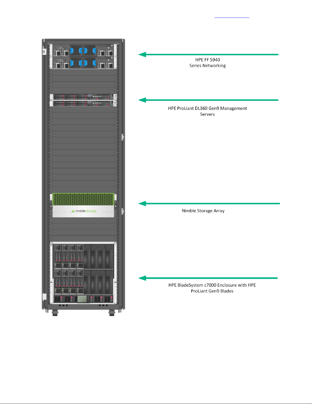
Every HPE Converged Architecture 700 with Nimble Storage deployment contains the following components:
• Ethernet switches: A pair of HPE FlexFabric 5940 10/40 GbE switches
• Storage: Nimble Storage arrays with a converged fabric-attached topology
• Computing resources:
• Industry-leading HPE ProLiant Gen9 serverbladesintheHPEBladeSystemc7000chassisformfactor
• A pair of standalone HPE ProLiant Gen9 rack mount servers for solution management
• Hypervisor: VMware vSphere 6.5
The testing described in this deployment guide was performed in May 2017.
Target Audience
The target audience for this deployment guide is solution engineers, distributors, and value-added resellers
who are HPE authorized partners. Readers can use this document to achieve the following goals:
• Gain insight into the value proposition for the HPE Converged Architecture 700 with Nimble Storage
solution.
8Copyright©2017 by Nimble Storage, Inc. All rights reserved.
Page 9

Business Need
• Better understand the component requirements for the solution.
• Better understand the recommended software and features that are part of the solution.
• Leverage design guidance to architect the solution to fit a particular set of business cases.
• Better understand the design considerations related to fault tolerance, performance, and scalability when
architecting the solution.
The HPE Converged Architecture 700 with Nimble Storage is intended for midsize businesses, large
enterprises, and IT service providers who are looking for and understand the value from the combination of
consolidation, efficiency, and consistency enabled by the solution.
Documentation Feedback
Business Need
One of the biggest challenges for IT is to provide a wide variety of software services with appropriate service
levelsand performance for the applications and services that customers need. New workloads and business
demands are forcing customers to reevaluate the way they buy and manage infrastructure.
Rather than do-it-yourself systems or integrated systems assembled from components that are provided by
multiple vendors, customers want pre-engineered systems and support from a single vendor. They need
repeatable and flexible building blocks that are tuned to handle unpredictable workloads. These systems
must deliver fast time-to-value and must include software-defined management of servers, storage, and
networking that automates all layers of the data center and streamlines routine tasks.
The HPE Converged Architecture 700 with Nimble Storage combines industry-leading HPE x86 servers,
storage arrays from Nimble Storage, HPE 5940 Series network switches, and a validated management
software stack to provide a highly available, scalable, and high-performing virtualization platform from one
vendor, HPE. These components are configured according to HPE best practices, providing a prescriptively
defined foundation onto which IT workloads can be deployed.
Terms and Abbreviations
The followingtermsandabbreviationsappearfrequentlyinthisdeploymentguide.Youcanusethedefinitions
in this list as a quick reference for how the terms apply to the HPE Converged Architecture 700 with Nimble
Storage.
bridge aggregation
The HPE name for link aggregation. Link aggregation combines multiple network interface connections on
a network deviceto increase throughput beyondthelev elthatasingleconnectioncansustain.Italsoprovides
redundancy if a link fails.
HPE Insight Control server provisioning (ICsp)
A virtual appliance that is used to install and configure HP ProLiant servers. ICsp uses resources such as
OS build plans and scripts to run deployment jobs.
HPE Integrated Lights-Out (iLO)
The proprietary HPE embedded server management technology that provides out-of-band management
capabilities.
HPE Intelligent Resilient Framework (IRF)
A technology in HPE Comware-based switchesthatconverges up to nine network devices into a single fabric
(on both the management and control planes) through physical IRF ports. The configuration of all devices
that participate in the IRF configuration is managed through a single IP address, and all network switches
in the IRF configuration look like one device to the network components.
HPE OneView
A powerfulconvergedmanagementappliancethatsimplifiesthedeploymentandmanagementofconverged
infrastructure services. HPE OneView is an appliance virtual machine (VM) that runs on the VMware
management server cluster.
9Copyright©2017 by Nimble Storage, Inc. All rights reserved.
Page 10

Terms and Abbreviations
Documentation Feedback
HPE ROM-Based Setup Utility (RBSU)
A utility that has a menu-driven interface and a BIOS serial CLI that allow users to perform configuration
activities on the server.
HPE Service Pack for ProLiant (SPP)
A consolidated set of solution-tested HPE ProLiant system software (firmware, drivers, agents, and utilities)
that is available as a single download from an easy-to-use website. You spend less time on maintenance
with resulting confidence in the stability of the update.
logical interconnect group
Groups of Virtual Connect interconnects that share a common network and storage configuration. HPE
OneView administrators create logical interconnect groups.
management servers
The VMware 6.5–based ESXi™DL360 Gen9 servers that host the VMs for management and for other
infrastructure.
management VM
The Windows Server®2012 R2–based VM that is used as the HPE ICsp media server and that runs the
HPE OneView for vCenter plugin software. This VM can also be the primary management system for the
solution, managing the VMware vSphere hosts and the Nimble Storage arrays.
multi-active detection (MAD)
A mechanism that manages switches during an IRF failure. MAD detects other switches in the IRF stack
that come online as masters and keeps online only the switch with the lowest master IRF ID. The others
shut down their interfaces, effectively removing them from the network, and stopping any network loops.
virtual local area network (VLAN)
A method for segmenting a network into related groups, which improves the efficiency of traffic flow and
limits the propagation of multicast and broadcast messages. Traffic between VLANs is blocked unless the
VLANs are connected by a router, which increases security.
virtual storage attached network (VSAN)
The virtual SAN fabric that carries storage traffic throughout the solution.
10Copyright©2017 by Nimble Storage, Inc. All rights reserved.
Page 11

System Setup
Documentation Feedback
System Setup
To deploy the HPE ConvergedArchitecture 700 with Nimble Storagesolution, youmustcompletethefollowing
tasks:
• Lay out the physical infrastructure.
• Complete the configuration worksheet.
• Configure the network.
• Configure the HPE compute infrastructure.
• Configure the management servers:
• Configure the hypervisor for the management server.
• Deploy the VMware vCenter Management Appliance.
• Build the management VM.
• Configure the storage arrays:
• Deploy the Nimble Storage arrays.
• Configure the converged SAN network.
• Configure the Nimble Storage vCenter integration.
• Deploy the Nimble Storage datastores to the management hosts.
• Configure the HPE management software:
• Deploy HPE OneView.
• Deploy HPE ICsp.
• Deploy the HPE OneView for VMware vCenter plugin.
• Configure the compute servers:
• Build the compute servers.
• Deploy the Nimble Storage datastores to the compute hosts.
11Copyright©2017 by Nimble Storage, Inc. All rights reserved.
Page 12
Validated Software and Firmware Levels
Figure 1: Configuration tested and verified by HPE and Nimble Storage
Documentation Feedback
Validated Software and Firmware Levels
The HPE Converged Architecture 700 with Nimble Storage solution was thoroughly tested to validate the
design and the interoperability of the components. The precise software and firmware versions that were
tested in the lab are presented in the sections that follow.
12Copyright©2017 by Nimble Storage, Inc. All rights reserved.
Page 13

HPE Service Pack for ProLiant
Documentation Feedback
HPE Service Pack for ProLiant
The following table lists the HPE Service Pack for ProLiant (SPP) firmware versions for the infrastructure
components that were verified for the solution. Access to the SPP requires validation from the HPE Support
Center. An active warranty or HPE Support agreement is required to download the SPP. Unless otherwise
noted, the listed components are included in the HPE SPP.
Table 1: HPE Service Pack for ProLiant
Verified VersionComponent
2017.04HPE Service Pack for ProLiant
4.60HPE Onboard Administrator
4.45HPE Virtual Connect
ROM Version: I36 v2.40 (02/17/2017)HPE ProLiant BL460c Gen9
ROM Version: P89 v2.40 (02/17/2017)HPE ProLiant DL360 Gen9
2.53*HPE Integrated Lights-Out 4 (iLO 4)
5.04HPE Smart ArrayP440ar/2GFIO Controller (DL360 Gen9)
5.04HPE Smart Array P244br/1G FIO Controller (BL460c)
bc 1.46 ncsi 1.3.16.0HPE Ethernet 1Gb 4-port 331i Adapter (Broadcom)
11.1.183.62HPE FlexFabric10Gb2P 556FLR-SFP+ Adapter (Emulex)
11.1.183.62HPE FlexFabric 20Gb 2P 650FLB Adapter (Emulex)
Note Components marked with an asterisk (*) are not included in the SPP. For these components, you must
build a custom firmware bundle. For instructions on how to create the bundle, see Create a Custom SSP in
the HPE OneView 3.0 User Guide.
Nimble Storage Software
The following table lists the Nimble Storage software components and versions that were verified for the
solution.
Table 2: Nimble Storage software
Verified VersionComponent
4.3NimbleOS
4.1.0.132Nimble Windows Toolkit
4.1.0Nimble Connection Manager for VMware ESXi 6.5
HPE Infrastructure Firmware
The followingtableliststheinfrastructurefirmware components and versionsthat were verifiedforthesolution.
The firmware versions noted in the table are not contained in the SPP; they must be downloaded separately
to a local repository. For update procedures for these components, see the documentation for the respective
component.
13Copyright©2017 by Nimble Storage, Inc. All rights reserved.
Page 14

HPE Infrastructure Software
Table 3: HPE infrastructure firmware
Verified VersionComponent
2.50HPE Intelligent Provisioning
7.1.070, Release 2606HPE FF 5940-4Slot
2.00.0038HPE metered and switched power distribution unit
Documentation Feedback
HPE Infrastructure Software
The following table lists the HPE infrastructure software components and versions that were verified for the
solution.
Table 4: HPE infrastructure software
Verified VersionComponent
3.0.07HPE OneView
7.6HPE Insight Control server provisioning (ICsp)
VMware Infrastructure Software
The followingtableliststhe infrastructure software components and versions related to VMware vSphere that
were verified for the solution.
Table 5:VMware infrastructure software
Current Supported VersionComponent
6.5 (Build: 4602587) (ISO Build: 4602587)VMware vCenter Server
6.5 (Build: 5224529)VMware vSphere
HPE Custom Image for VMware ESXi 6.5
HPE Customized VMware Image
HPE publishes a separate VMware recipe specific to HPE ProLiant hardware to ensure compatibility of driver
and firmware releases with the VMware ESXi hypervisor. The recipe details the HPE customized VMware
image and the components necessary for a successful deployment of ESXi. The relevant components in the
recipe are listed in the table.
HPE publishes a new version of the HPE customized image in the following scenarios:
• When HPE publishes a new SPP
• When HPE publishes a new Maintenance Supplement Bundle (MSB)
• When VMware publishes a new OS release
• When VMware publishes a new update release
• When HPE releases a hotfix for a critical driver or a firmware fix
VMware-ESXi-6.5.0-OS-Release-5146846HPE-650.9.6.5.27-May2017 (6.5)
8.2.1HPE OneView for VMware vCenter
2012 R2 (Standard Edition)Windows Server (Windows®management VMs)
The driversforthenetworkandstoragecontrollersintheProLiantserversareintegratedintheHPEcustomized
image and are not part of the generic ESXi image that is distributed by VMware. ESXi requires the drivers
14Copyright©2017 by Nimble Storage, Inc. All rights reserved.
Page 15

Resources for Physical Deployment
for these key controllers to be integrated with the base image. You will not be prompted to install key drivers
during the installation process for ESXi.
For more information about the HPE customized image, see Getting Started with HPE Customized Images
in the Software Delivery Repository - vibsdepot (aka HPE Online Depot) site.
For more information about deploying and updating VMware software on HPE ProLiant servers, including
adding VMware patches or hotfixes to the HPE customized image, see the technical white paper Deploying
and updating VMware vSphere on HPE ProLiant servers.
Windows Server VM
The Windows Server VM is used as a centralized management server within the solution and as a place to
install Windows components, such as the Windows-based VMware vCenter deployment. HPE recommends
applying Microsoft updates to the VM in accordance with your data center's operations policies.
For information about available hotfixes, visit the Microsoft Support site.
Documentation Feedback
Resources for Physical Deployment
Compute Physical Deployment
HPE BladeSystem c7000 Enclosure
Forsite requirements, installation instructions, and other general reference materials, see HPE BladeSystem
c7000 Enclosures on the HPE Support Site.
HPE ProLiant BL460c Gen9 Servers
For site requirements, installation instructions, and other general reference materials, see HPE ProLiant
BL460c Gen9 Servers on the HPE Support Site.
HPE ProLiant WS460c Gen9 Graphics Server Blade
For site requirements, installation instructions, and other general reference materials, see HPE ProLiant
WS460c Gen9 Graphics Server Blade on the HPE Support Site.
HPE ProLiant WS460c Gen9 Graphics Expansion Blade
For site requirements, installation instructions, and other general reference materials, see HPE ProLiant
WS460c Gen9 Graphics Server Blade on the HPE Support Site.
HPE ProLiant BL660c Gen9 Servers
For site requirements, installation instructions, and other general reference materials, see HPE ProLiant
BL660c Gen9 Servers on the HPE Support Site.
HPE ProLiant DL360 Gen9 Servers
For site requirements, installation instructions, and other general reference materials, see HPE ProLiant
DL360 Gen9 Servers on the HPE Support Site.
Network Physical Deployment
HPE FlexFabric 5940 Switch Series
For site requirements, installation instructions, and other general reference materials, see HPE FlexFabric
5940 Switch Series on the HPE Support Site.
15Copyright©2017 by Nimble Storage, Inc. All rights reserved.
Page 16
Cabling for Networking, Storage, and Power
Documentation Feedback
Cabling for Networking, Storage, and Power
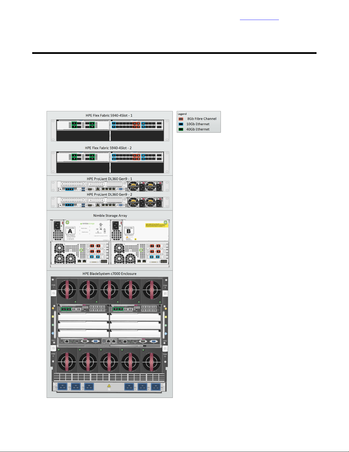
Network Cabling
The following diagram shows the SAN connections for the HPE Converged Architecture 700 with Nimble
Storage solution.
Figure 2: Cabling overview: SAN connections
16Copyright©2017 by Nimble Storage, Inc. All rights reserved.
Page 17

Network Cabling
Documentation Feedback
Detailed cabling information for each connection is provided in the following table.
Table 6: SAN connections with the HPE FF 5940-4Slot switch and the Nimble Storage array
PortDevicePortSwitch
Cabling
Code
1Interconnect 1 Q1HPEBladeSystemc7000enclosure1/1/1HPE FF 5940-4Slot-1
2Interconnect 1 Q2HPEBladeSystemc7000enclosure1/1/2HPE FF 5940-4Slot-1
3Interconnect 2 Q1HPEBladeSystemc7000enclosure2/1/1HPE FF 5940-4Slot-2
4Interconnect 2 Q2HPEBladeSystemc7000enclosure2/1/2HPE FF 5940-4Slot-2
52/1/7HPE FF 5940-4Slot-21/1/7HPE FF 5940-4Slot-1
62/1/8HPE FF 5940-4Slot-21/1/8HPE FF 5940-4Slot-1
7PCI 1-1HPE ProLiant DL360 Gen9 -11/2/1HPE FF 5940-4Slot-1
8PCI 1-2HPE ProLiant DL360 Gen9 -12/2/1HPE FF 5940-4Slot-2
9PCI 1-1HPE ProLiant DL360 Gen9 -21/2/2HPE FF 5940-4Slot-1
10PCI 1-2HPE ProLiant DL360 Gen9 -22/2/2HPE FF 5940-4Slot-2
11FC5Nimble Storage controller A1/2/13HPE FF 5940-4Slot-1
12FC6Nimble Storage controller A2/2/13HPE FF 5940-4Slot-2
13FC9Nimble Storage controller A1/2/14HPE FF 5940-4Slot-1
14FC10Nimble Storage controller A2/2/14HPE FF 5940-4Slot-2
The following diagram shows the 1 GbE connections that are used for management.
15FC5Nimble Storage controller B1/2/15HPE FF 5940-4Slot-1
16FC6Nimble Storage controller B2/2/15HPE FF 5940-4Slot-2
17FC9Nimble Storage controller B1/2/16HPE FF 5940-4Slot-1
18FC10Nimble Storage controller B2/2/16HPE FF 5940-4Slot-2
19tg1Nimble Storage controller A1/2/17HPE FF 5940-4Slot-1
20tg2Nimble Storage controller A2/2/17HPE FF 5940-4Slot-2
21tg1Nimble Storage controller B1/2/18HPE FF 5940-4Slot-1
22tg2Nimble Storage controller B2/2/18HPE FF 5940-4Slot-2
17Copyright©2017 by Nimble Storage, Inc. All rights reserved.
Page 18
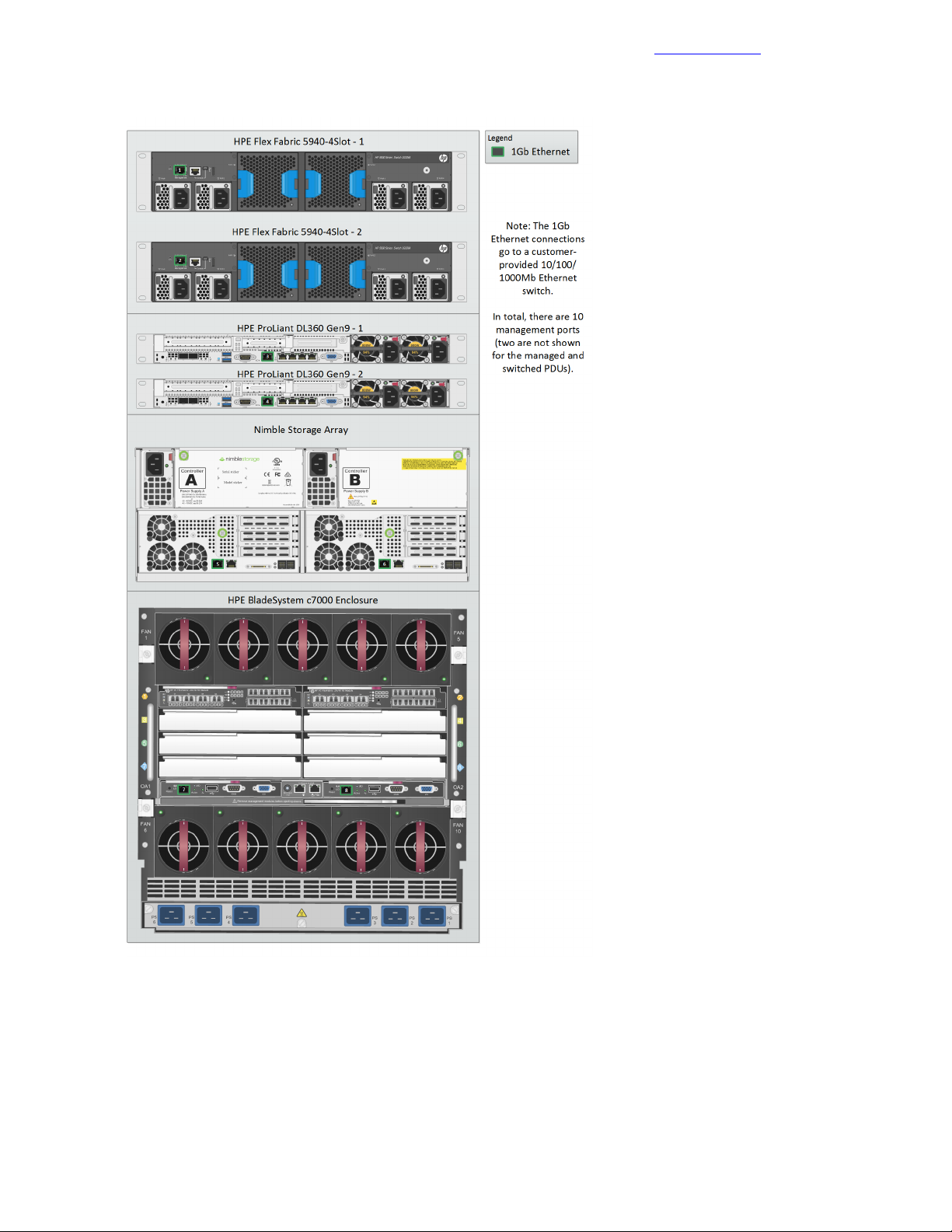
Power Cabling
Figure 3: Cabling overview: 1 GbE connections for management
Documentation Feedback
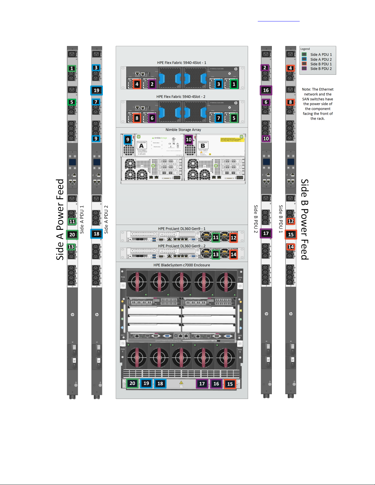
Power Cabling
The following diagram shows the power connections for the HPE Converged Architecture 700 with Nimble
Storage solution.
18Copyright©2017 by Nimble Storage, Inc. All rights reserved.
Page 19
Power Cabling
Figure 4: Power cabling overview
Documentation Feedback
Detailed information for each power connection is provided in the following table.
19Copyright©2017 by Nimble Storage, Inc. All rights reserved.
Page 20

Power Cabling
Documentation Feedback
Table 7: Power configuration with HPE switching and 4 x HPE 4.9kVA 208 Volt L6-30 input
(20xC13/4xC19) NA/JP managed PDU (H8B50A)
PortPDUPortDevice
Cabling
Code
1L2 – 11Side A PDU 1PS 1HPE FF 5940-4Slot-1
2L2 – 11Side B PDU 2PS 2HPE FF 5940-4Slot-1
3L2 – 11Side A PDU 2PS 3HPE FF 5940-4Slot-1
4L2 – 11Side B PDU 1PS 4HPE FF 5940-4Slot-1
5L2 – 7Side A PDU 1PS 1HPE FF 5940-4Slot-2
6L2 – 7Side B PDU 2PS 2HPE FF 5940-4Slot-2
7L2 – 7Side A PDU 2PS 3HPE FF 5940-4Slot-2
8L2 – 7Side B PDU 1PS 4HPE FF 5940-4Slot-2
9L2 – 1Side A PDU 2PS 1Nimble Storage array controller A
10L2 – 1Side B PDU 2PS 1Nimble Storage array controller B
11L2 – 9Side A PDU 1PS 2HPE ProLiant DL360 Gen9 – 1
12L2 – 9Side B PDU 1PS 1HPE ProLiant DL360 Gen9 – 1
13L1 – 7Side A PDU 1PS 2HPE ProLiant DL360 Gen9 – 2
14L1 – 7Side B PDU 1PS 1HPE ProLiant DL360 Gen9 – 2
15L1 – 8Side B PDU 1PS 1HPEBladeSystemc7000enclosure
16L2 – 8Side B PDU 2PS 2HPEBladeSystemc7000enclosure
17L1 – 8Side B PDU 2PS 3HPEBladeSystemc7000enclosure
18L1 – 8Side A PDU 2PS 4HPEBladeSystemc7000enclosure
19L2 – 8Side A PDU 2PS 5HPEBladeSystemc7000enclosure
20L1 – 8Side A PDU 1PS 6HPEBladeSystemc7000enclosure
20Copyright©2017 by Nimble Storage, Inc. All rights reserved.
Page 21

Preparing to Install and Configure the HPE Converged Architecture 700 with Nimble Storage
Documentation Feedback
Preparing to Install and Configure the HPE Converged
Architecture 700 with Nimble Storage
The Configuration Worksheet
Appendix A: Configuration Worksheet on page 97 lists the variables that are required to complete the tasks
in this deployment guide. Before beginning the deployment of an HPE Converged Architecture 700 with
Nimble Storage, ensure that the configuration worksheet is completed with the correct and validated values.
You are free to expand the configuration worksheet to suit your needs.
Fully Qualified Domain Names Versus IP Addresses
All components that are deployed with the HPE Converged Architecture 700 with Nimble Storage must have
correct forward and reverse domain name system (DNS) entries in the network DNS server. This guide
assumes that the site where the HPE Converged Architecture 700 with Nimble Storage will be deployed
already has a DNS server and that the server configuration will be modified to accommodate the HPE
ConvergedArchitecture700withNimbleStorage .YoucanalsodeployandconfigureaDNSserverspecifically
for use with this solution; however, the deployment steps for a DNS server are not covered in the guide.
Throughout the guide, when you are asked to enter the IP address of a component, you can, most of the
time, use the DNS name or the fully qualified domain name (FQDN) of the component instead. Although you
can use just IP addresses, HPE recommends that you use DNS names whenever possible. The solution
requires a valid DNS server with host name entries for every component even if you use only IP addresses.
HPE Resources for Automation Efforts
This deployment guide covers the manual steps that are required to build a verified configuration of the HPE
Converged Architecture 700 with Nimble Storage. The guide covers no automation, except the automation
that is built into products; for example, HPE OneView for VMware vCenter Enhanced Grow Cluster.
Libraries (such as REST, Python, Java, and PowerShell libraries) that you can use for automation efforts are
available for most of the components of the HPE Converged Architecture 700 with Nimble Storage. You can
use these resources to streamline deployments.
HPE OneView
HPE OneView API Reference and HP OneView 2.0 REST API Reference
HPE OneView REST API scripting help
HPE OneView SDK and Libraries on GitHub
HPE Insight Control server provisioning
HP Insight Control server provisioning API Reference:
https://<<icsp_mgmt_ip>>/api-docs/current/#about
Note To access this reference, you must be logged in to a deployed instance of HPE ICsp.
HPE Insight Control server provisioning SDK and Libraries on GitHub
HPE Integrated Lights Out
iLO RESTful API Data Management Model Reference (iLO 4)
21Copyright©2017 by Nimble Storage, Inc. All rights reserved.
Page 22

Connecting to the Components in the Solution
Managing Hewlett Packard Enterprise Servers Using the RESTful API
HPE Integrated Lights Out SDK and Libraries on GitHub
Nimble Storage Array
Nimble Storage REST API Reference
VMware
VMware API and SDK Documentation
Documentation Feedback
Connecting to the Components in the Solution
As you deploy the HPE Converged Architecture 700 with Nimble Storage solution, you will need to connect
to various components. Use the information in this section for guidance on how to connect to a specific
component during the solution build or as a general reference.
HPE iLO
Perform the steps in this procedure to logintotheHPEIntegratedLights-Out(iLO)ofanHPEProLiantserver.
Procedure
1 Using a web browser, navigate to the iLO to which you want to connect.
For example, to connect to the iLO of the first management server, navigate to
https://<<mgmt_server_1_ilo_ip>>.
2 Accept any security warnings to continue to the website.
3 Log in with the user name admin and the password <<mgmt_server_ilo_password>>.
4 To access the Integrated Remote Console, click the .NET link or the Java link on the Overview page.
HPE Onboard Administrator
Perform the steps in this procedure to log in to the active HPE Onboard Administrator of an enclosure.
Procedure
1 Using a web browser, navigate to https://<<enclosure_1_oa_1_ip>>.
2 Accept any security warnings to continue to the website.
3 Log in with the user name admin and the password <<enclosure_1_password>>.
4 Alternatively, connect to the Onboard Administrator CLI through an SSH connection, using PuTTY,
TeraTerm, or another SSH client.
Network Switches
How you connect to the network switches depends on whether networking has been configured on them. A
serial connection is always possible. If the switch is availableon the network, you can use an SSH connection
instead of a serial connection.
Procedure
1 Connect a serial cable between the deployment PC and the switch.
2 Using a terminal emulation program that supports serial connections (for example, TeraTerm), select the
correct serial port.
3 Configure the port settings for 9600 baud, 8-bits, no parity, 1 stop bit, and no flow control.
4 Log in:
22Copyright©2017 by Nimble Storage, Inc. All rights reserved.
Page 23

VMware Host Client
If the switch has not been configured yet, there is no user name and password.•
• If the switchhas been configured, the admin password should be <<net_switch_admin_passwor d>>.
5 If the switch has been configured and you want to connect through SSH, open an SSH connection to the
switch by using an SSH client, such as TeraTerm, and log in with the user name admin and the password
<<net_switch_admin_password>>.
Documentation Feedback
VMware Host Client
Perform the steps in this procedure to open the VMware Host Client to manage a local VMware ESXi node.
Procedure
1 Open a web browser on the management workstation and navigate to the ESXi node management IP
address; for example, <<mgmt_server_1_ip>>.
2 Accept any security warnings to continue to the website.
3 Click Open the VMware Host Client.
4 Log in with the user name root and the password <<mgmt_server_root_password>>.
5 Clear the Join CEIP checkbox and click OK.
VMware vSphere Client for Windows
Perform the steps in this procedure to download and install the vSphere Client for Windows application and
to use it to connect to VMware hosts or to vCenter.
Procedure
1 Download the client:
a Using a web browser, navigate to
http://vsphereclient.vmware.com/vsphereclient/5/1/1/2/5/0/8/VMware-viclient-all-6.0.0-5112508.exe.
b Download and install the vSphere Client for Windows.
You will later use the vSphere Web Client for administration tasks, but the thick client installed in this
step is used to ease installation.
c After you download and install the thick client, run the application.
A shortcut to the vSphere Client for Windows may have been added to the desktop.
2 Connect to a VMware host:
a In the vSphere Client application, enter the IP address or the host name for the host; for example,
<<mgmt_server_1_ip>.
b Log in with the user name root and the password <<mgmt_server_root_password>>.
c Click Login.
3 Connect to the VMware vCenter instance:
a Enter the IP address or the FQDN for vCenter; for example, <<vcenter_fqdn>>.
b Log in with the user name administrator@<<mgmt_net_domain_name>> and the password
<<vcenter_administrator_password>>.
VMware vSphere Web Client
Perform the steps in this procedure to connect to the vSphere Web Client.
Procedure
1 Using a web browser, navigate to https://<<vcenter_fqdn>>/vsphere-client.
23Copyright©2017 by Nimble Storage, Inc. All rights reserved.
Page 24

VMware vSphere Administration Portal
2 Accept any certificate warnings.
3 Log in with the user name administrator@<<mgmt_net_domain_name>> and the password
<<vcenter_administrator_password>>.
Documentation Feedback
VMware vSphere Administration Portal
Perform the steps in this procedure to connect to the VMware vSphere Administration Portal.
Procedure
1 Using a web browser, navigate to https://<<vcenter_mgmt_ip>>:5480.
2 Log in with the user name root.
3 Enter the password:
• If this is the first time that you log in to the portal, the default password is vmware.
• Otherwise, the password is <<vcenter_root_password>>.
VMware VM Console: vSphere Web Client
Perform the steps in this procedure to open a VM console from the vSphere Web Client.
Procedure
1 Log in to the vSphere Web Client.
2 From the Home page, click VMs and Templates.
3 In the left pane, expand the data tree to display the VM for which you want to open the console.
4 Click the VM to select it:
a Click the Summary tab for the VM.
b Click Launch Console.
You may have to allow pop-up windows in the browser for the console window to open.
c Accept any security warnings in the new browser window or tab that opens.
VMware VM Console: vSphere Client for Windows
Perform the steps in this procedure to open a VM console from the vSphere Client for Windows application.
Procedure
1 Log in to the vSphere Client for Windows.
2 From the Home page, click VMs and Templates.
3 In the left pane, expand the data tree to display the VM for which you want to open the console.
4 Right-click the VM and choose Open Console:
a To enter console commands, click anywhere in the console window or use the mouse in the console.
b To release the keyboard and the mouse from the console, press and release Ctrl+Alt.
c To send a Ctrl-Alt-Del sequence to the VM, click VM > Guest > Send Ctrl+Alt+Del from the console
toolbar.
HPE OneView Web Administration Portal
Perform the steps in this procedure to log in to the HPE OneView Web Administration Portal.
If you are uploading a file to HPE OneView, such as a patch update or the HPE Service Pack for ProLiant,
do not use Microsoft Internet Explorer to upload the update package because this browser cannot handle
large file sizes. Use Google Chrome or Mozilla Firefox to complete this setup.
24Copyright©2017 by Nimble Storage, Inc. All rights reserved.
Page 25

HPE OneView for vCenter Plugin Administrator Console
Procedure
1 Using a web browser, navigate to https://<<oneview_fqdn>>.
2 Accept any security warnings to continue to the website.
3 Log in with the user name Administrator and the password <<oneview_administrator_password>>.
Documentation Feedback
HPE OneView for vCenter Plugin Administrator Console
Perform the steps in this procedure to log in to the HPE OneView for vCenter Plugin Administrator Console.
Procedure
1 Using a web browser, navigate to https://<<ov4vc_fqdn>>/ui/index.html.
2 Accept any security warnings to continue to the website.
3 Log in with the user name Admin and the password <<ov4vc_admin_password>>.
Nimble Storage Array CLI
Perform the steps in this procedure by using a terminal editor to access the CLI of the Nimble Storage array
through SSH.
Procedure
1 Open a terminal emulator that supports SSH connections and connect to <<nimble_fqdn>>.
2 Log in with the user name admin and the password <<nimble_adm_pwd>>.
Nimble Storage Administrator Console
Perform the steps in this procedure to log in to the Nimble Storage array Administrator Console.
Procedure
1 Using a web browser, navigate to https://<<nimble_fqdn>>.
2 Accept any security warnings to continue to the website.
3 Log in with the user name admin and password <<nimble_adm_pwd>>.
HPE Insight Control Server Provisioning Web Administration Page
Perform the steps in this procedure to log in to the HPE ICsp Web Administration page.
Procedure
1 Using a web browser, navigate to https://<<icsp_fqdn>>.
2 Accept any security warnings to continue to the website.
3 Log in with the user name Administrator and the password <<icsp_administrator_password>>.
25Copyright©2017 by Nimble Storage, Inc. All rights reserved.
Page 26

Configuring the Ethernet Network
Documentation Feedback
Configuring the Ethernet Network
The HPE Converged Architecture 700 with Nimble Storage has been validated with the HPE FlexFabric
5940-4Slot switch. The HPE FlexFabric 5940-slot-2QSFP+ switch can also be leveraged for deployments,
but those steps are not documented in this guide.
The following procedures describe how to configure the HPE FlexFabric 5940-4Slot switches for use in a
base HPE Converged Architecture 700 with Nimble Storage environment. Before configuring the switches,
make sure that they are running the HPE Comware version specified in Validated Software and Firmware
Levels on page 12. A base HPE Converged Architecture 700 with Nimble Storage deployment must use a
minimum of two of the same model network switches.
Set Up IRF Configuration
The procedure for configuring the Intelligent Resilient Framework (IRF) begins at switch A, moves to switch
B, and concludes back at switch A.
Procedure
1 Starting at the serial port of HPE FlexFabric 5940-4Slot switch A, configure the switch.
At initial boot and connection to the serial or console port of the switch, the Comware setup should
automatically start and attempt to enter automatic configuration.
Note When instructions call for network configuration in system-view context, if you are at the <HPE>
prompt, issue the system-view command to get to the [HPE] prompt.
Startup configuration file does not exist.
Started automatic configuration, press CTRL_C or CTRL_D to break.
Automatic configuration attempt: 1.
Not ready for automatic configuration: no interface available.
Waiting for the next...
Automatic configuration attempt: 2.
Interface used: M-GigabitEthernet0/0/0.
Enable DHCP client on M-GigabitEthernet0/0/0.
M-GigabitEthernet0/0/0 failed to obtain IP address.
Interface used: Vlan-interface1.
Enable DHCP client on Vlan-interface1.
Vlan-interface1 failed to obtain IP address.
Waiting for the next... Line aux0 is available.
Press ENTER to get started.
<HPE> system-view
System View: return to User View with Ctrl+Z.
2 Configure the IRF ports.
[HPE] interface range FortyGigE 1/1/7 to FortyGigE 1/1/8
[HPE-if-range] shutdown
[HPE-if-range] quit
[HPE] irf-port 1/1
[HPE-irf-port1/1] port group interface FortyGigE 1/1/7
[HPE-irf-port1/1] port group interface FortyGigE 1/1/8
[HPE-irf-port1/1] quit
26Copyright©2017 by Nimble Storage, Inc. All rights reserved.
Page 27

Set Up IRF Configuration
[HPE]save
The current configuration will be written to the device. Are you sure? [Y/N]:y
Please input the file name(*.cfg)[flash:/startup.cfg]
(To leave the existing filename unchanged, press the enter key):
3 Moving to the serial port of HPE FlexFabric 5940-4Slot switch B, configure the switch.
Startup configuration file does not exist.
Started automatic configuration, press CTRL_C or CTRL_D to break.
Automatic configuration attempt: 1.
Not ready for automatic configuration: no interface available.
Waiting for the next...
Automatic configuration attempt: 2.
Interface used: M-GigabitEthernet0/0/0.
Enable DHCP client on M-GigabitEthernet0/0/0.
M-GigabitEthernet0/0/0 failed to obtain IP address.
Interface used: Vlan-interface1.
Enable DHCP client on Vlan-interface1.
Vlan-interface1 failed to obtain IP address.
Waiting for the next...
Line aux0 is available.
Press ENTER to get started.
<HPE> system-view
System View: return to User View with Ctrl+Z.
Documentation Feedback
4 Change the IRF member ID and reboot the switch.
[HPE] irf member 1 renumber 2
Renumbering the member ID may result in configuration change or loss.
Continue?[Y/N] y
[HPE] save
The current configuration will be written to the device. Are you sure? [Y/N]:y
Please input the file name(*.cfg)[flash:/startup.cfg]
(To leave the existing filename unchanged, press the enter key):
Validating file. Please wait...
Saved the current configuration to mainboard device successfully.
[HPE] quit
<HPE> reboot
Start to check configuration with next startup configuration file, please
wait.........DONE!
This command will reboot the device.
Continue? [Y/N]:y
Now rebooting, please wait...
5 When the switch reboot is complete, configure the IRF ports.
<HPE> system-view
[HPE] interface range FortyGigE 2/1/7 to FortyGigE 2/1/8
[HPE-if-range] shutdown
[HPE-if-range] quit
[HPE] irf-port 2/2
[HPE-irf-port2/2] port group interface FortyGigE 2/1/7
[HPE-irf-port2/2] port group interface FortyGigE 2/1/8
[HPE-irf-port2/2] quit
27Copyright©2017 by Nimble Storage, Inc. All rights reserved.
Page 28

Configure Multi-Active Detection and Remote Access to the Switch
[HPE] irf-port-configuration active
[HPE] interface range FortyGigE 2/1/7 to FortyGigE 2/1/8
[HPE-if-range] undo shutdown
[HPE-if-range] quit
[HPE] save
The current configuration will be written to the device. Are you sure? [Y/N]:y
Please input the file name(*.cfg)[flash:/startup.cfg]
(To leave the existing filename unchanged, press the enter key):
flash:/startup.cfg exists, overwrite? [Y/N]:y
Validating file. Please wait...
Saved the current configuration to mainboard device successfully.
[HPE]
6 Back at HPE FlexFabric 5940-4Slot switch A, enable the IRF ports on switch A.
<HPE> system-view
[HPE] irf-port-configuration active
[HPE] interface range FortyGigE 1/1/7 to FortyGigE 1/1/8
[HPE-if-range] undo shutdown
[HPE-if-range] quit
Documentation Feedback
7 Allow switch B to reboot to merge into the IRF fabric.
Fromthis point on, allconfigurations happen only on switchA. No further configurationisneeded on switch
B because the control and management planes have been merged as a part of the IRF configuration.
Configure Multi-Active Detection and Remote Access to the Switch
HPErecommendsimplementing a multi-active detection (MAD) mechanism, which is useful forthese purposes:
• To detect the presence of multiple identical IRF fabrics
• To handle collisions
• To recover from faults in the unlikely event of an IRF split or failure
For more information, see the HPE FlexFabric 5940 IRF Configuration Guide. This guide explains how to
use the management links to configure MAD Bidirectional Forwarding Detection (BFD).
Note The switch configuration code in this procedure does not include switch prompts.
Procedure
1 Fromsystem-view,run the following commands, substituting the values from the configuration worksheet.
interface M-GigabitEthernet 0/0/0
ip address <<net_switch_mgmt_ip>> <<mgmt_net_netmask>>
mad bfd enable
mad ip address <<net_switch1_mad_ip>> <<mad_net_netmask>> member 1
mad ip address <<net_switch2_mad_ip>> <<mad_net_netmask>> member 2
quit
ip route-static 0.0.0.0 0.0.0.0 <<mgmt_net_gw>>
local-user admin
password simple <<net_switch_admin_password>>
authorization-attribute user-role network-admin
service-type ssh terminal
28Copyright©2017 by Nimble Storage, Inc. All rights reserved.
Page 29

Configure IRF Priority
quit
ssh server enable
user-interface vty 0 63
authentication-mode scheme
protocol inbound ssh
quit
user-interface aux 0 1
authentication-mode scheme
quit
save
2 Create the public keys on the switch.
public-key local create rsa
Input the modulus length [default = 1024]:Enter
public-key local create dsa
Input the modulus length [default = 1024]:Enter
public-key local create ecdsa secp256r1
Documentation Feedback
3 SSH to the switch by using <<net_switch1_mgmt_ip>>, the user name admin, and the password
<<net_switch_admin_password>>.
Configure IRF Priority
Configure the domain and IRF parameters. The <<net_switch_domain_id>> value is an arbitrary number,
but it must be unique from other IRF domains.
Procedure
1 From system-view, run the following commands:
irf domain <<net_switch_domain_id>>
irf member 1 priority 32
irf member 2 priority 30
irf mac-address persistent always
Convert the Chassis Working Mode
To configure the interfaces and the switch to use FC or FCoE, you must convert the system working mode.
Before running the commands, make sure that both switches are merged into the IRF fabric.
Procedure
1 From system-view, run the following commands:
system-working-mode advance
Do you want to change the system working mode? [Y/N]:y
The system working mode is changed, please save the configuration and reboot
29Copyright©2017 by Nimble Storage, Inc. All rights reserved.
Page 30

Configure NTP
the system to make it effective.
return
save
reboot
Configure NTP
Network Transport Protocol (NTP) must be configured on the switch.
Procedure
1 From system-view, run the following commands:
clock protocol none
return
clock datetime 13:28:00 02/17/2016
system-view
ntp-service unicast-server <<mgmt_net_ntp1>> priority
clock protocol ntp
Documentation Feedback
save
Configure the VLANs Needed
To create the necessary VLANs, perform this procedure on both switches.
Procedure
1 From system-view, run the following commands:
vlan <<mgmt_net_vlan>>
name MGMT-VLAN
quit
vlan <<deployment_net_vlan>>
name Native-Deployment-VLAN
quit
vlan <<mgmt_vmotion_net_vlan>>
name MGMT-vMotion-VLAN
quit
vlan <<mgmt_ft_net_vlan>>
name MGMT-FT-VLAN
quit
vlan <<compute_vmotion_net_vlan>>
name Compute-vMotion-VLAN
quit
vlan <<compute_ft_net_vlan>>
name Compute-FT-VLAN
quit
30Copyright©2017 by Nimble Storage, Inc. All rights reserved.
Page 31

Convert Interfaces to Use FC Protocol
vlan <<vm_production_net_1_vlan>>
name VM-Production-VLAN1
quit
vlan <<fcoe_san_a_vlan>>
name FCoE-SAN-A-VLAN
description FCOE SAN A (VSAN <<net_fcoe_vsan_a_id>>)
quit
vlan <<fcoe_san_b_vlan>>
name FCoE-SAN-B-VLAN
description FCOE SAN B (VSAN <<net_fcoe_vsan_b_id>>)
quit
save
Convert Interfaces to Use FC Protocol
Convert the needed ports to serve as Fibre Channel (FC) ports.
Documentation Feedback
Procedure
1 From system-view, run the following command:
interface range Ten-GigabitEthernet 1/2/1 to Ten-GigabitEthernet 1/2/6
Ten-GigabitEthernet 2/2/1 to Ten-GigabitEthernet 2/2/6
port-type fc
Add Individual Port Descriptions for Troubleshooting
Add individual port descriptions for troubleshooting activity and verification. The following examples use a
single Nimble Storage array with dual controllers.
Procedure
1 From system-view, run the following commands:
interface FortyGigE 1/1/1
description <<enclosure_1_name>>-VC1:Q1
quit
interface FortyGigE 1/1/2
description <<enclosure_1_name>>-VC1:Q2
quit
interface FortyGigE 2/1/1
description <<enclosure_1_name>>-VC2:Q1
quit
interface FortyGigE 2/1/2
description <<enclosure_1_name>>-VC2:Q2
quit
interface FortyGigE 1/1/7
description Switch1-IRF-Switch2-IRF-2/1/7
quit
interface FortyGigE 1/1/8
31Copyright©2017 by Nimble Storage, Inc. All rights reserved.
Page 32

Configure Global FCoE Parameters
description Switch1-IRF-Switch2-IRF-2/1/8
quit
interface FortyGigE 2/1/7
description Switch2-IRF-Switch1-IRF-1/1/7
quit
interface FortyGigE 2/1/8
description Switch2-IRF-Switch1-IRF-1/1/8
quit
interface Fc1/2/13
description <<nimble_system_name>> CA-fc5
quit
interface Fc1/2/14
description <<nimble_system_name>> CA-fc9
quit
interface Fc1/2/15
description <<nimble_system_name>> CB-fc5
quit
interface Fc1/2/16
description <<nimble_system_name>> CB-fc9
quit
interface Fc2/2/13
description <<nimble_system_name>> CA-fc6
quit
interface Fc2/2/14
description <<nimble_system_name>> CA-fc10
quit
interface Fc2/2/15
description <<nimble_system_name>> CB-fc6
quit
interface Fc2/2/16
description <<nimble_system_name>> CB-fc10
quit
Documentation Feedback
interface Ten-GigabitEthernet 1/2/1
description <<mgmt_server_1_hostname>>-LOM1
quit
interface Ten-GigabitEthernet 1/2/2
description <<mgmt_server_2_hostname>>-LOM1
quit
interface Ten-GigabitEthernet 2/2/1
description <<mgmt_server_1_hostname>>-LOM2
quit
interface Ten-GigabitEthernet 2/2/2
description <<mgmt_server_2_hostname>>-LOM2
quit
save
Configure Global FCoE Parameters
Configuring the Fibre Channel over Ethernet (FCoE) mode requires configuring quality of service (QoS) for
Data Center Bridging Exchange on the switch. Configuring QoS for Data Center Bridging Exchange also
prevents FCoE traffic in the switch from being blocked and ensures that the FCoE traffic is lossless.
Procedure
1 On the switch, run the following commands from system-view to configure the Enhanced Transmission
Selection local precedence QoS table.
32Copyright©2017 by Nimble Storage, Inc. All rights reserved.
Page 33

Configure Interface FCoE Parameters
Level 3 (Critical Applications) must be set to the highest level to ensure that FCoE traffic is given the
highest priority.
qos map-table dot1p-lp
import 0 export 0
import 1 export 0
import 2 export 0
import 3 export 1
import 4 export 0
import 5 export 0
import 6 export 0
import 7 export 0
quit
2 Create an access control list (ACL) in the switch to allow FCoE (Ethernet protocol number 0x8906) and
FCoE Initiation Protocol (FIP) (Ethernet Protocol 0x8914) packets to pass through the switch.
This rule is also applied to the DCBX traffic classifier (created in a later step). FCoE and FIP packets on
the switch receive the highest priority because they are mapped to 802.1p priority value 3.
acl number 4000 name DCBX
rule 0 permit type 8906 ffff
rule 5 permit type 8914 ffff
quit
Documentation Feedback
3 Create a traffic classifier rule called DCBX with the operator class OR, and map it to ACL 4000, which
was created in the previous step.
traffic classifier DCBX operator or
if-match acl 4000
quit
4 Create a traffic behavior named DCBX and configure it to mark packets with an 802.1.p priority of 3.
traffic behavior DCBX
remark dot1p 3
quit
5 Create a QoS policy that associates the traffic classifier created in step 3 with the traffic behavior created
in step 4, and specify that this classifier-behavior mode is associated with DCBX.
qos policy DCBX
classifier DCBX behavior DCBX mode dcbx
quit
save
Configure Interface FCoE Parameters
To enable FCoE traffic to be passed to the CNAs of the management servers and to each enclosure, you
must configure the interface with LLDP, DCBX support, and the previously created QoS policy.
Procedure
1 In system-view, configure priority flow control and spanning tree.
To prevent FCoE packets from being dropped, enable priority flow control and ensure that any packet
with the dot1p classifier of 3 is not dropped and is forwarded. Also, setting the interfaces to edge ports in
33Copyright©2017 by Nimble Storage, Inc. All rights reserved.
Page 34

Configure the FCoE Mode and VSANs
spanning tree ensures that if spanning tree is enabled on the switch as part of the configuration, these
ports directly transition to the forwarding state in the spanning tree topology.
interface range FortyGigE 1/1/1 to FortyGigE 1/1/3 FortyGigE 2/1/1 to FortyGigE
2/1/3 Ten-GigabitEthernet 1/2/17 to Ten-GigabitEthernet 1/2/18
Ten-GigabitEthernet 2/2/17 to Ten-GigabitEthernet 2/2/18
priority-flow-control auto
priority-flow-control no-drop dot1p 3
qos trust dot1p
stp edged-port
2 Configure LLDP and DNCX TLV advertising on the interfaces.
Runthe following commands in system-viewwhile still on the interfacerange from step 1 of this procedure:
lldp tlv-enable dot1-tlv dcbx
qos apply policy DCBX outbound
3 Enable weighted round robin (WRR) on the interfaces, setting 50 percent of the bandwidth to networking
for best effort (be) and 50 percent of the bandwidth to storage traffic for assured forwarding (af1).
Set the rest of the WRR values to strict priority because they are not being used. Run the following
commands in system-view while still on the interface range from step 1 of this procedure:
Documentation Feedback
qos wrr be group 1 byte-count 5
qos wrr af1 group 1 byte-count 5
qos wrr af2 group sp
qos wrr af3 group sp
qos wrr af4 group sp
qos wrr ef group sp
qos wrr cs6 group sp
qos wrr cs7 group sp
quit
save
Configure the FCoE Mode and VSANs
This procedure enables FCoE mode on the switch and sets it to Fibre Channel forwarder (FCF) mode. It also
creates the VSANs for FCoE SAN A and FCoE SAN B and attaches them to the appropriate VLAN IDs.
Procedure
1 In system-view, set the FCoE mode to FCF.
fcoe-mode fcf
2 Create the VSAN for FCoE SAN A and set the domain ID.
vsan <<net_fcoe_vsan_a_id>>
domain-id <<net_fcoe_vsan_a_domain_id>> preferred
Non-disruptive reconfiguration or isolating the switch may be performed.
Continue? [Y/N]:y
quit
34Copyright©2017 by Nimble Storage, Inc. All rights reserved.
Page 35

Add FC Interfaces to the Appropriate VSANs
3 Create the VSAN for FCoE SAN B and set the domain ID.
vsan <<net_fcoe_vsan_b_id>>
domain-id <<net_fcoe_vsan_b_domain_id>> preferred
Non-disruptive reconfiguration or isolating the switch may be performed.
Continue? [Y/N]:y
quit
4 Associate the VSAN for FCoE SAN A with the VLAN for SAN A.
vlan <<fcoe_san_a_vlan>>
fcoe enable vsan <<net_fcoe_vsan_a_id>>
quit
5 Associate the VSAN for FCoE SAN B with the VLAN for SAN B.
vlan <<fcoe_san_b_vlan>>
fcoe enable vsan <<net_fcoe_vsan_b_id>>
quit
Add FC Interfaces to the Appropriate VSANs
Documentation Feedback
This procedure associates all FC interfaces on HPE FlexFabric 5940-4Slot switch A with the VSAN for FCoE
SAN A and all FC interfaces on HPE FlexFabric 5940-4Slot switch B with the VSAN for FCoE SAN B.
Procedure
1 In system-view, associate the FC interfaces on HPE FlexFabric 5940-4Slot switch A with the VSAN for
FCoE SAN A.
interface range Fc 1/2/1 to Fc 1/2/12
port access vsan <<net_fcoe_vsan_a_id>>
2 Associate the FC interfaces on HPE FlexFabric 5940-4Slot switch B with the VSAN for FCoE SAN B.
interface range Fc 2/2/1 to Fc 2/2/12
port access vsan <<net_fcoe_vsan_b_id>>
Configure SNMPv3
SNMPv3 must be configured properly on the switches to enable HPE OneView to manage them.
Procedure
1 In system-view, configure SNMPv3.
snmp-agent
snmp-agent community read <<net_snmp_ro_string>>
snmp-agent sys-info contact <<net_snmp_contact_info>>
snmp-agent sys-info location HPE CA700 <<net_switch1_hostname>>
snmp-agent sys-info version v3
snmp-agent group v3 admin write-view <<net_snmp_wr_string>>
snmp-agent mib-view included SolutionRW iso
snmp-agent mib-view included SolutionRW snmp
snmp-agent mib-view included view1 iso
35Copyright©2017 by Nimble Storage, Inc. All rights reserved.
Page 36

Create Bridge Aggregations
snmp-agent usm-user v3 <<net_snmp_user>> user-role network-admin simple
authentication-mode sha <<net_snmp_user_password>> privacy-mode aes128
<<net_snmp_user_password>>
save
Documentation Feedback
Create Bridge Aggregations
Bridge aggregations must be configured for each enclosure and each management server.
Procedure
1 In system-view, create a bridge aggregation for each Virtual Connect module in each enclosure.
interface Bridge-Aggregation 111
link-aggregation mode dynamic
description <<enclosure_1_name>>-VC1
quit
interface Bridge-Aggregation 112
link-aggregation mode dynamic
description <<enclosure_1_name>>-VC2
quit
interface range name <<enclosure_1_name>> interface Bridge-Aggregation111
Bridge-Aggregation112
quit
interface range FortyGigE 1/1/1 to FortyGigE 1/1/3
port link-aggregation group 111
quit
interface range FortyGigE 2/1/1 to FortyGigE 2/1/3
port link-aggregation group 112
quit
interface range name <<enclosure_1_name>>
port link-type trunk
undo port trunk permit vlan 1
port trunk pvid vlan <<deployment_net_vlan>>
port trunk permit vlan <<deployment_net_vlan>> <<mgmt_net_vlan>>
<<compute_vmotion_net_vlan>> <<compute_ft_net_vlan>>
<<vm_production_net_1_vlan>>
quit
2 Add the appropriate FCoE VLAN to the appropriate bridge aggregation for the enclosure.
Note At this point, only the VLANs are added. The VLAN for SAN A is added to Bridge-Aggregation 111
and the VLAN for SAN B to Bridge-Aggregation 112. When the VSANs are configured later, SAN A is
isolated to IRF member 1 and SAN B to IRF member 2.
interface Bridge-Aggregation 111
port trunk permit vlan <<fcoe_san_a_vlan>>
quit
interface Bridge-Aggregation 112
port trunk permit vlan <<fcoe_san_b_vlan>>
quit
36Copyright©2017 by Nimble Storage, Inc. All rights reserved.
Page 37

Uplink into the Existing Network Infrastructure
3 Create a bridge aggregation for each management server.
interface Bridge-Aggregation 11
description <<mgmt_server_1_hostname>>
quit
interface Bridge-Aggregation 12
description <<mgmt_server_2_hostname>>
quit
interface range name mgmt_servers interface Bridge-Aggregation11
Bridge-Aggregation12
quit
interface range Ten-GigabitEthernet 1/2/17 Ten-GigabitEthernet 2/2/17
port link-aggregation group 11
quit
interface range Ten-GigabitEthernet 1/2/18 Ten-GigabitEthernet 2/2/18
port link-aggregation group 12
quit
interface range name mgmt_servers
port link-type trunk
undo port trunk permit vlan 1
port trunk pvid vlan <<deployment_net_vlan>>
port trunk permit vlan <<deployment_net_vlan>> <<mgmt_net_vlan>>
<<mgmt_vmotion_net_vlan>> <<fcoe_san_a_vlan>> <<fcoe_san_b_vlan>>
quit
Documentation Feedback
save
Note The bridge aggregations created in this procedure do not become fully operational until the
management and compute servers are deployed with VMware vSphere as described in this guide.
Uplink into the Existing Network Infrastructure
Depending on the available network infrastructure, several methods and features can be used to uplink the
HPE Converged Architecture 700 with Nimble Storage environment. HPE recommends using bridge
aggregations to uplink the HPE FlexFabric 5940-4Slot switches in the HPE Converged Architecture 700 with
Nimble Storage environment into the infrastructure.
The preceding procedures can be used to create an uplink bridge aggregation to the existing environment.
After configuration is complete, be sure to run the save command to save the configuration on each switch.
37Copyright©2017 by Nimble Storage, Inc. All rights reserved.
Page 38

Configuring the Computing Infrastructure and the Management Servers
Documentation Feedback
Configuring the Computing Infrastructure and the
Management Servers
Configuration involves the following tasks:
• Configuring iLO on the management servers (and applying iLO Advanced licenses, if necessary)
• Configuring the c7000 enclosures
• Installing and configuring the management servers
• Deploying the VMware vCenter Management Appliance
• Building the management VM
Configuring iLO
Each management server’s Integrated Lights-Out (iLO) configuration must be completed manually to assign
each server an iLO IP address.The configuration process also adds a user to the iLO environment to manage
the solution. The purpose of adding a user is to allow the default “Administrator” account and password to
remain unaltered. This solution admin user is manually created during the iLO configuration.
Note The iLO Advanced licenses might have been installed by the HPE factory, depending on how you
purchased your OneView licensing. Perform the steps to install the iLO Advanced licenses only if they are
not already installed.
Install iLO Advanced Licenses
If the iLO Advanced licenses were not installed in the factory,locate the HPE OneView license keys from the
paper documentation for the server. Each DL360 includes an HPE OneView license.
Figure 5: Example of HPE OneView key (with iLO)
The information highlighted in yellow is the HPE part number that identifies whether this is a key for the DL
platform. In this example, E5Y43A is the part number forthe "HPE OneView for ProLiant DL Server, including
3years 24x7 Support FIO Bundle Physical 1 Server" license.
The information highlighted in green is the iLO Advanced license key string that you must manually enter into
the DL360 iLOs to enable advancedfeatures,such as the remote console and the Virtual Media components.
You must enter the key before proceeding with the iLO configuration.
Configure iLO
Before starting to configure iLO, ensure that all firmware components are at the correct levels as specified
in this document.
Procedure
1 Connect and enter the ROM-based setup utility (RBSU):
a Connect the keyboard and monitor to the first DL360 Gen9.
38Copyright©2017 by Nimble Storage, Inc. All rights reserved.
Page 39

Configure iLO
b Power up the server.
c Press F9 when the server POST displays F9 System Utilities on the bottom of the screen.
d Select System Configuration and press Enter.
e Select BIOS/Platform Configuration (RBSU) and press Enter.
2 Configure the date and time:
a Select Date and Time and press Enter.
b Select the month digits on Date and press Enter. Enter the month in the mm format and press Enter.
c Use the right arrow to select the day digits and press Enter. Enter the day in the dd format and press
Enter.
d Use the right arrow to select the year digits and press Enter. Enter the year in the yyyy format and
press Enter.
e Select the hour digits on Time and press Enter. Enter the hour in the hh format and press Enter.
f Use the right arrow to select the minute digits and press Enter. Enter the minutes in the mm format
and press Enter.
g Select Time Zone and press Enter. Select the appropriate time zone and press Enter.
h Press F10 to save. Enter Y to saveand exit. After the Changes Saved pop-up window displays, press
Enter.
3 Configure the iLO IP information – IP Information:
a Press ESC to go to the BIOS menu and again to go to the System Configuration menu.
b Select iLO 4 Configuration Utility and press Enter.
c Select Network Options and press Enter.
d Select DHCP Enable and press Enter. In the pop-up, select OFF and press Enter.
e Select DNS Name and press Enter. Enter <<mgmt_server_1_ilo_hostname>> and press Enter.
f Select IP Address and press Enter. Enter <<mgmt_server_1_ilo_ip>>and press Enter.
g Select Subnet Mask and press Enter. Enter <<mgmt_net_netmask>> and press Enter.
h Select Gateway IP Address and press Enter. Enter <<mgmt_net_gw>> and press Enter.
i Press F10 to save the configuration.
j Enter Y to save and exit.
k Press Enter on the iLO Needs to Reset pop-up window.
l Wait30 seconds for the iLO to reset, and then try to reconnect to the iLO and open the remote console.
m Press Enter on the iLO is Resetting pop-up window again and then ESC.
n Press ESC to go to the iLO 4 Configuration Utility menu, again to go to the Systems Configuration
menu, and again at the System Utilities menu.
o Press Enter to exit RBSU and Enter again to reboot.
p Select Reboot the System and press Enter to reboot the system.
Documentation Feedback
4 Configure the iLO IP information – Advanced Network Options:
a Press F9 when the server POST displays F9 System Utilities at the bottom of the screen.
b Select System Configuration and press Enter.
c Select iLO 4 Configuration Utility and press Enter.
d Select Advanced Network Options and press Enter.
e Select Gateway from DHCP and press Enter. In the pop-up, select Disabled and press Enter.
f Select DHCP Routes and press Enter. In the pop-up window, select Disabled and press Enter.
g Select Gateway from DHCP and press Enter. In the pop-up window,select Disabledand press Enter.
h Select DNS from DHCP and press Enter. In the pop-up window, select Disabled and press Enter.
i Select DNS Server 1 and press Enter. Enter <<mgmt_net_dns1>> and press Enter.
j Select WINS from DHCP and press Enter. In the pop-up window, select Disabled and press Enter.
k Select Domain Name and press Enter. In the pop-up window,enter <<mgmt_net_domain_name>>
and press Enter.
39Copyright©2017 by Nimble Storage, Inc. All rights reserved.
Page 40

Configuring the c7000 Enclosures
l Press F10 to save the configuration.
m Enter Y to save and exit.
n Press Enter on the iLO Needs to Reset pop-up window.
o Wait 30 seconds for the iLO to reset, and then try to reconnect to the iLO and open the remote console.
p Press Enter on the iLO is Resetting pop-up window again and then ESC.
q Press ESC to go to the iLO 4 Configuration Utility menu, again to go to the Systems Configuration
menu, and again at the System Utilities menu. Press Enter to exit RBSU and Enter again to reboot.
5 Add the admin user to iLO:
a Press F9 when the server POST displays F9 System Utilities on the bottom of the screen.
b Select System Configuration and press Enter.
c Select iLO 4 Configuration Utility and press Enter.
d Select User Management and press Enter.
e Select Add User and press Enter.
f Review all of the new user iLO4 privileges and ensure they are all set to Yes.
g Select New User Name and press Enter.
h Enter admin and press Enter.
i Select Login Name and press Enter. Enter admin and press Enter.
j Select Password and press Enter. Enter <<mgmt_server_ilo_password>> and press Enter.
k Confirm the password by retyping <<mgmt_server_ilo_password>> and press Enter.
l Press Enter on the iLO Needs to Reset pop-up window.
m Press Enter on the iLO is Resetting pop-up window.
n Press Enter when you see the Changes Saved! pop-up window.
o Press ESC to go to the iLO 4 Configuration Utility menu, again to go to the Systems Configuration
menu, and again at the System Utilities menu. Press Enter to exit RBSU and Enter again to reboot.
Documentation Feedback
6 Repeat the procedure for each management server in the configuration:
a Power down the server before it continues with the boot sequence.
b Apply the license as described in Install iLO Advanced Licenses on page 38.
c Repeat this process for the other management server in the solution, using the variables that are
appropriate for that server.
Configuring the c7000 Enclosures
These procedures describe how to configure an HPE BladeSystem c7000 chassis for use in the HPE
Converged Architecture 700 with Nimble Storage.
Assign IP Addresses to the c7000 Enclosures from the Insight Display
Use this procedure to configure the basic network parameters for each enclosure from the physical Insight
display on the front of each c7000 enclosure.
40Copyright©2017 by Nimble Storage, Inc. All rights reserved.
Page 41
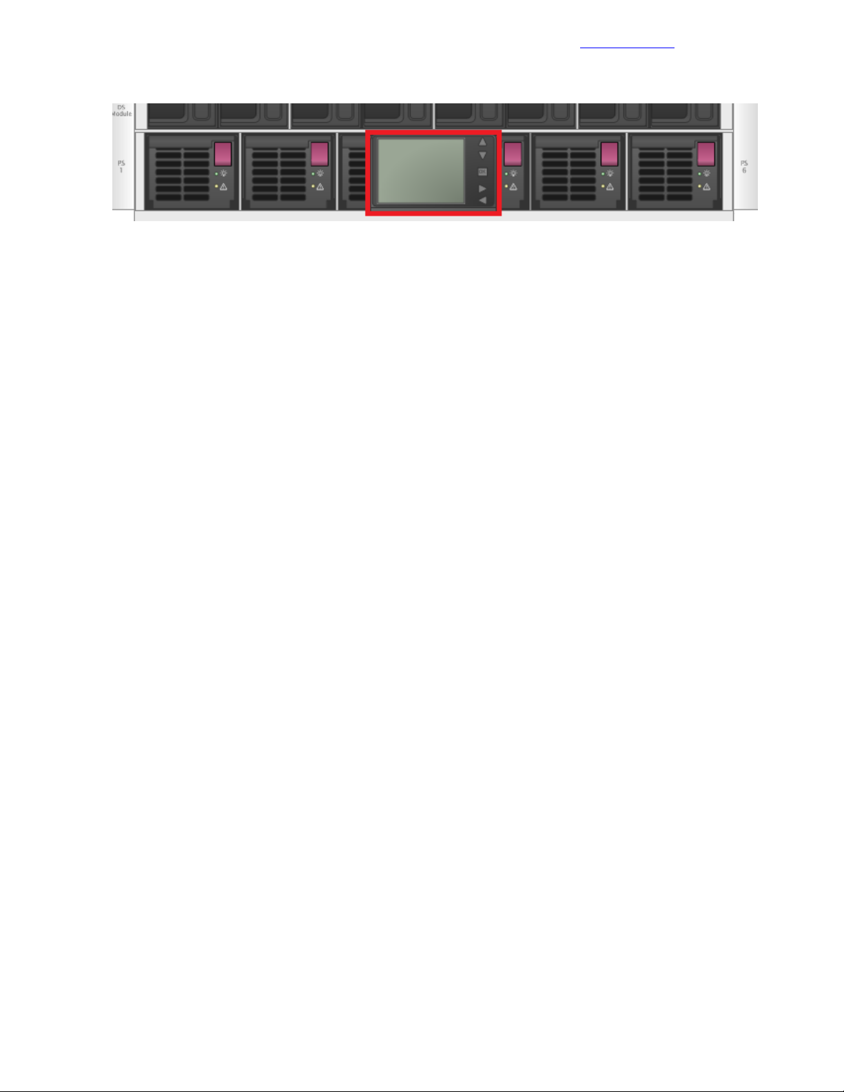
Configure Enclosures with the OA Wizard
Documentation Feedback
Figure 6: Insight display located on front of c7000 enclosure
Procedure
1 Starting with the first enclosure in the first compute rack, press OK to activate the Insight display on the
front of the enclosure.
2 Use the arrow buttons to scroll to Enclosure Settings and press OK.
3 Scroll to OA1 IPV6 and press OK.
4 Scroll to OA1 IPV4 and press OK.
5 Change network mode from DHCP to Static and press OK.
6 Navigate to Accept and press OK.
7 Set the following parameters:
• IP Address: <<enclosure_1_oa_1_ip>>.
• Subnet Mask: <<mgmt_net_netmask>>.
• Default Gateway: <<mgmt_net_gw>>.
8 Navigate to Accept and press OK.
9 Using the information provided on the configuration worksheet, repeat this procedure to set the network
information on each enclosure in the solution.
Configure Enclosures with the OA Wizard
Further configure each enclosure through the web UI.
Procedure
1 Log in and configure Onboard Administrator (OA):
a Connect to the primary HPE Onboard Administrator for the first enclosure.
b If a security warning appears, choose the option Continue to this website (not recommended) to
proceed.
c Log in to the OA as the administrator, with the Admin user ID and the password from the Pull tag on
the OA module.
d On the First Time Setup Wizard Welcome page, click Next.
e On the FIPS page, click Skip.
f On the Enclosure Selection page, click Next.
g On the Configuration Management page, click Skip.
h On the Rack and Enclosure Settings page, complete the following fields and click Next:
• Rack Name: Enter the appropriate name.
• Enclosure Name: <<enclosure_1_name>>.
• Asset Tag (optional): Enter the asset tag for the system if required.
i On the Administrator Account Setup page, click Skip.
2 Add the admin user:
41Copyright©2017 by Nimble Storage, Inc. All rights reserved.
Page 42

Configure Enclosures with the OA Wizard
On the Local User Accounts page, click New.a
b In the pop-up window, provide the identifying information:
• User Name: admin.
• Enter and Confirm Password: <<enclosure_1_password>>.
• Privilege Level: Administrator.
• User Permissions group box: Select the Onboard Administrator Bays checkbox.
• Add User: Click Add User and add any additional users requested.
c Back on the Local User Accounts page, click Next.
d On the EBIPA page, click Skip because this task is performed later.
e On the Directory Groups page, click Skip .
f On the Directory Settings page, click Skip.
3 Configure the OA IP address information:
a On the Onboard Administrator Network Settings page, click Next.
b For each OA in the enclosure, ensure that Use static IP settings for each active Onboard
Administrator is selected and the appropriate information is entered.
OA1 is used in this example:
• DNS Host Name: <<enclosure_1_oa_1_hostname>>.
• IP Address: <<enclosure_1_oa_1_ip>>.
• Subnet Mask: <<mgmt_net_netmask>>.
• Gateway: <<mgmt_net_gw>>.
• DNS Server 1: <<mgmt_net_dns1>>.
Documentation Feedback
c In the warning dialog box, click Next and click OK.
If you changed the information for the Active Onboard administrator, you must reconnect to the OA.
d On the IPv6 page, deselect the Enable IPv6 checkbox and click Next.
42Copyright©2017 by Nimble Storage, Inc. All rights reserved.
Page 43
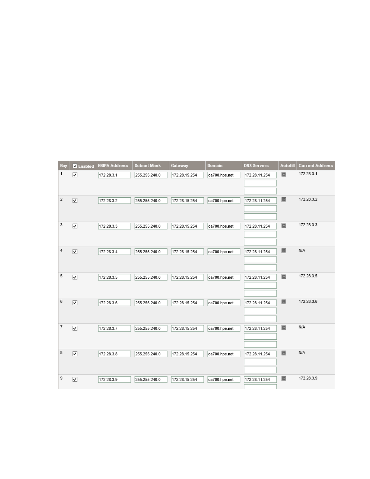
Configure Enclosure Bay IP Addressing
Documentation Feedback
e On the SNMP Settings page, click Skip.
4 Configure the power and finish the wizard:
a On the Power Management page, select AC Redundant and click Next.
b On the Finish page, ensure that Do not automatically show this wizard again is checked, and click
Finish.
Configure Enclosure Bay IP Addressing
After the Enclosure wizard is finished, the next task is to configure the enclosure bay IP addressing (EBIPA)
so that the blade iLOs and the enclosure interconnects can obtain IP addresses.
Procedure
1 From the left side of the UI, select Enclosure Information > Enclosure Bay IP Addressing > IPv4.
2 On the Device tab for bay 1, enter the IP address, subnet mask, gateway, domain, and DNS servers in
the appropriate fields of the configuration worksheet.
3 Choose the appropriate option for populating the EBIPA information in the rest of the blades:
• If the IP information is contiguous for all blades in the enclosure, click Autofill.
• If it is not contiguous, enter the information for each blade manually based on the configuration sheet.
43Copyright©2017 by Nimble Storage, Inc. All rights reserved.
Page 44

Create Admin User for All iLOs
4 Click the Enable option for each blade (or for all blades) as required.
If you used the autofill option, delete the IP addresses from the blades as appropriate.
5 Click Apply.
6 On the Interconnect tab, for the first interconnect, enter the IP address, subnet mask, gateway, domain,
and DNS servers in the appropriate fields of the configuration worksheet.
7 Choose the appropriate option for populating the EBIPA information in the rest of the blades:
• If the IP information is contiguous for all blades in the enclosure, click Autofill .
• If it is not contiguous, enter the information for each blade manually based on the configuration sheet.
8 Click the Enable option for each blade (or for all blades) as required.
If you used the autofill option, delete the IP addresses from the blades as appropriate.
9 Click Apply.
10 Log out of the enclosure.
Documentation Feedback
Create Admin User for All iLOs
This procedure creates an admin account with administrative privileges on each blade in the enclosure.
Procedure
1 Using a terminal emulation program, open an SSH session to the active Onboard Administrator.
2 In the SSH window, enter the identifying information for the enclosure:
• IP Address: <<enclosure_1_oa_1_ip>>.
• Username: admin.
• Password: <<enclosure_1_password>>.
3 Run the following command to create an admin user on each blade iLO in the enclosure, replacing
<<blade_ilo_admin_password>> with the appropriate value:
HPONCFG all << end_marker
<RIBCL VERSION="2.0">
<LOGIN USER_LOGIN="adminname" PASSWORD="password">
<USER_INFO MODE="write">
<ADD_USER
USER_NAME="admin"
USER_LOGIN="admin"
PASSWORD="<<blade_ilo_admin_password>>">
<ADMIN_PRIV value ="Yes"/>
<REMOTE_CONS_PRIV value ="Yes"/>
<RESET_SERVER_PRIV value ="Yes"/>
<VIRTUAL_MEDIA_PRIV value ="Yes"/>
<CONFIG_ILO_PRIV value="Yes"/>
</ADD_USER>
</USER_INFO>
</LOGIN>
</RIBCL>
end_marker
4 Exit the OA SSH session by typing exit and pressing Enter.
Repeat c7000 Configuration Procedures for Each Enclosure in the Solution
Repeat the procedures in this chapter for each HPE BladeSystem c7000 in the solution.
44Copyright©2017 by Nimble Storage, Inc. All rights reserved.
Page 45

Configuring the Server and Installing the Hypervisor forthe Management Servers
Documentation Feedback
Configuring the Server and Installing the Hypervisor for the Management
Servers
The management servers are built manually to host the management infrastructure of the solution. The
management server environment is a requirement for deploying and configuring the remaining components
of the solution.
You must use the HPE custom image for VMware ESXi 6.5 for this task. This image is also required later for
setting up HPE ICsp and building the ProLiant server blades. Before beginning these procedures, ensure
that all firmware components are at the levels specified in Validated Software and Firmware Levels on page
12.
Perform the followingprocedures on the first management server and then repeat for the second management
server in the solution, or, alternatively, perform the procedures in parallel on both management servers
simultaneously:
• Configure the Smart Array P440ar RAID level.
• Install VMware vSphere 6.5 on the DL360 Gen9 server.
Launch iLO Remote Console and Power On the Server
Before you can begin configuring the array, you must launch the Integrated Remote Console and power on
the server.
Procedure
1 Open a connection and log in to the first management server’s iLO.
2 Launch the Integrated Remote Console by selecting either .NET or Java from the Information Overview
window.
3 If prompted, click Run to allow the remote console to open.
4 With the server in the powered-off state, power on the server by selecting Power Switch > Momentary
Press.
Enter Intelligent Provisioning and Configure the Smart Array
Procedure
1 Press F10 when appropriate to enter Intelligent Provisioning.
2 When the splash screen appears, select Smart Storage Administrator.
3 Click Smart Array P440ar from the Array Controller(s) list under Available Device(s) in the left pane:
a Click Configure under the Actions list in the right pane.
b Click Create Array under the Actions list in the right pane.
c Select the drives you want to use for the new array and then click Create Array in the lower right.
4 Select RAID 1+0 as the RAID level and leave the defaults for the remaining options.
5 Click Create Logical Drive in the lower right.
6 If spare drive configuration is needed, click Manage Spare Drives:
a Select the spare drive type that you want to use.
HPE recommends selecting Auto Replace Drives so that drives are automatically added to the RAID
array if a drive fails.
b Select drives to use as spares.
c Click Save.
7 Confirm the array details and click Finish.
45Copyright©2017 by Nimble Storage, Inc. All rights reserved.
Page 46

Continue Intelligent Provisioning Configuration and Install Wizard to Install Hypervisor
8 Click the X icon in the upper right, and then click OK to exit the HPE Smart Storage Administrator.
Documentation Feedback
Continue Intelligent Provisioning Configuration and Install Wizard to Install Hypervisor
Procedure
1 Set the following options for the OS Selection step:
• OS Family: VMware ESXi/vSphere Custom Image.
• Installation: Customized.
• Source Media: Physical DVD.
2 Attach the HPE custom image for ESXi 6.5 through iLO Virtual Media.
3 On the Remote Console window, select Virtual Drives > Image File CD-ROM/DVD from the iLO options
menu bar and navigate to the .iso file located on the deployment system.
4 Select the image and click Open.
5 Click the Continue > icon in the lower-right pane.
6 Intelligent Provisioning scans the .iso image to ensure that it is a valid ESXi image.
The warning Only VMware Custom images should be used! displays. If the image is the correct HPE
Custom Image as stated in the CA700 Architectural Policies document, you may proceed.
7 Set the following options for the OS Information Step:
• Host Name: <<mgmt_server_1_hostname>>.
• Root Password, and Re-enter Root Password: <<mgmt_server_root_password>>.
• Network Type: Static.
• IP Address: <<mgmt_server_1_ip>>.
• Subnet Mask: <<mgmt_net_netmask>>.
• Default Gateway: <<mgmt_net_gw>>.
• DNS: <<mgmt_net_dns1>>.
8 Click the Continue icon in the lower-right pane.
9 Confirm the information presented, and click Continue.
10 Intelligent Provisioning installs ESXi on the management server.
This process takes several minutes and causes the system to reboot.
11 When the ESXi installation is finished, a pop-up message states that the server must be rebooted. Press
Enter to reboot the server.
12 The server reboots and loads to the ESXi start screen. Leave the iLO Remote Console window open to
continue configuring the host.
13 Repeat this procedure for the other management servers in the configuration.
Configuring the Management Server After Hypervisor Installation
Perform the followingprocedures on the first management server and then repeat for the second management
server in the solution. You may perform these steps in parallel on both management servers simultaneously.
There are three general tasks to accomplish:
• Configure vSphere host parameters through the ESXi host UI.
• Configure vSphere host parameters from the CLI.
• Upload software files to the first management server.
Configure vSphere Host Network Parameters Through the ESXi Host UI
This procedure configures an ESXi host with access to the management network.
46Copyright©2017 by Nimble Storage, Inc. All rights reserved.
Page 47

Configure the vSwitch Failover Policy
Documentation Feedback
Procedure
1 After the server has finished rebooting, press F2 to customize the system.
2 Log in as root, enter the corresponding password<<mgmt_server_root_password>>, and press Enter.
3 Select the Configure the Management Network option and press Enter.
4 Select the Network Adapters option and press Enter.
5 Select vmnic4 and vmnic5.
These vmnics correspond to the Embedded FlexibleLOM ports, and they should display a status of
Connected if the network cables have been connected and are active.
6 Press Enter to confirm the Network Adapter selections.
7 If the Management network VLAN is not a native (untagged) VLAN, select VLAN (optional) and press
Enter.
8 Enter <<mgmt_net_vlan>> and press Enter.
9 Select Custom DNS Suffixes.
10 Enter <<mgmt_net_domain_name>> and press Enter.
11 Press Esc to exit the Configure Management Network submenu.
12 Press Y to confirm the changes and return to the main menu.
Configure the vSwitch Failover Policy
You must configure a policy to specify how the vSwitch will handle failover.
Procedure
1 From the System Customization menu, select Troubleshooting Options and press Enter.
2 Select Enable ESXi Shell and press Enter.
3 Press Alt and F1 at the same time.
4 Log in with the user name root and the password <<mgmt_server_root_password >>.
47Copyright©2017 by Nimble Storage, Inc. All rights reserved.
Page 48

Download the VMware vSphere Client for Windows
5 Enter the following command to set up the vSwitch load-balancing policy:
esxcli network vswitch standard portgroup policy failover set –p "Management
Network" -l iphash
6 Type exit to log out of the console.
7 Press Alt and F2 at the same time.
8 Select Disable ESXi Shell and press Enter.
9 Press Esc to exit Troubleshooting Options.
10 Select Test Management Network to verify that the management network is set up correctly, and then
press Enter.
11 Press Enter to run the test.
12 Press Enter to exit the window.
13 Press Esc to log out of the VMware console.
14 Repeat this procedure for the other management servers in the configuration.
Documentation Feedback
Download the VMware vSphere Client for Windows
Procedure
1 Using a web browser, navigate to
http://vsphereclient.vmware.com/vsphereclient/5/1/1/2/5/0/8/VMware-viclient-all-6.0.0-5112508.exe.
2 Download and install the vSphere Client for Windows.
Note This application is downloaded from the VMware website. Therefore, Internet access is required on
the management workstation.
Log in to VMware ESXi Hosts with the VMware vSphere Client for Windows
Log in to each ESXi host with the vSphere Client for Windows.
Procedure
1 Open the downloaded VMware vSphere Client for Windows and connect to the first management server.
2 Openanotherinstance of the VMware vSphere Client for Windows and connect to the secondmanagement
server.
Set Up VMkernel Ports and Virtual Switches
Set up the VMkernel ports and virtual switches on each ESXi host.
Procedure
1 From the vSphere Client, click the host in the inventory.
2 Click the Configuration tab and, in the Hardware pane, click Networking.
3 On the right side of vSwitch0, click Properties:
a From the Ports tab, select vSwitch and click Edit.
b From the General tab, change the MTU to 9000.
c From the NIC Teaming tab, change Load Balancing to Route based on IP Hash.
d Ensure that both vmnic4 and vmnic5 are in the Active Adapters section.
If they are not, move them to that section.
e Click OK to close the properties for vSwitch0.
4 Select the Management Network configuration and click Edit:
48Copyright©2017 by Nimble Storage, Inc. All rights reserved.
Page 49

Set Up VMkernel Ports and Virtual Switches
Documentation Feedback
Change the network label to VMkernel-MGMT and select the Management Traffic checkbox:a
• If the <<mgmt_net_vlan>> is 1 or untagged, ensure that the VLAN is set to 0 (None).
• If the <<mgmt_net_vlan>> has a value other than 1 or untagged, set <<mgmt_net_vlan>> as the
VLAN ID and click OK.
b Click OK to finalize the edits for the management network.
5 Select the VM Network configuration and click Edit:
a Change the network label to Management:
• If the <<mgmt_net_vlan>> is 1 or untagged, ensure that the VLAN is set to 0 (None).
• If the <<mgmt_net_vlan>> has a value other than 1 or untagged, set <<mgmt_net_vlan>> as the
VLAN ID and click OK.
b Click OK to finalize the edits for the management port group.
6 Optional:Ifusingaseparatenetwork as a deployment network (not running deployment overManagement),
click Add to add a network element:
a Select Virtual Machine and click Next.
b Change the network label to Deployment.
Do not specify a VLAN ID because the deployment network must be a native VLAN.
c Click Next and then Finish to finalize the creation of the Deployment network.
7 To add the vMotion network, click Add to add a network element:
a Select VMkernel and click Next.
b Change the network label to VMkernel-vMotion and enter <<mgmt_vmotion_net_vlan>> in the
VLAN ID (Optional) field.
c Select the Use This Port Group for vMotion checkbox.
d Click Next to continue with vMotion VMkernel creation.
e Enter the vMotion IP address <<mgmt_server_1_vmotion_ip>> and subnet mask
<<mgmt_vmotion_net_netmask>> for the host.
f Click Next and Finish to finalize the creation of the vMotion VMkernel interface.
8 Select the VMkernel-vMotion configuration and click Edit:
a Change the MTU to 9000.
b Click OK to finalize the edits for the VMkernel-vMotion network.
9 To add the Fault Tolerant network, click Add to add a network element:
a Select VMkernel and click Next.
b Change the network label to VMkernel-FT and enter <<mgmt_ft_net_vlan>> in the VLAN ID (Optional)
field.
c Select the Use This Port Group for Fault Tolerance Logging checkbox.
d Click Next to continue with vMotion VMkernel creation.
e Enterthe vMotion IP address <<mgmt_server_1_ft_ip>> andsubnet mask <<mgmt_ft_net_netmask>>
for the host.
f Click Next and Finish to finalize the creation of the VMkernel-FT interface.
10 Select the VMkernel-FT configuration and click Edit:
a Change the MTU to 9000.
b Click OK to finalize the edits for the VMkernel-FT network.
11 Close the dialog box to finalize the ESXi host networking setup.
12 Repeat this procedure for the other management servers in the configuration.
49Copyright©2017 by Nimble Storage, Inc. All rights reserved.
Page 50

Rename the Local Datastore
Rename the Local Datastore
Procedure
1 Click the Configuration tab and, in the Hardware pane, click Storage.
2 Right-click the local datastore and click Rename.
3 Rename the datastore to <<mgmt_server_1_hostname>> -localdatastore.
4 Repeat this procedure for the other management servers in the configuration.
Set Date and Time and Configure NTP
Procedure
1 Click the Configuration tab and, in the Software pane, click Time Configuration.
2 Toward the top right of the screen, click Properties:
a Adjust the date and time as appropriate for your installation.
b In the NTP Configuration group checkbox, select NTP Client Enabled.
c Click Options.
d In the General tab, click Start and stop with host.
e In the NTP Settings tab, click Add and enter the <<mgmt_net_ntp1>> value in the Address field,
then click OK.
f Check Restart NTP service to apply changes, and then click OK.
g Click OK to exit the Time Configuration window.
Documentation Feedback
3 Repeat this procedure for the other management servers in the configuration.
Deploying the VMware vCenter Management Appliance
These procedures provide detailed instructions for installing the VMware vCenter Management Appliance in
an HPE Converged Architecture 700 with Nimble Storage environment.
Prepare for the VMware vCenter Server Appliance Installer
Procedure
1 Fromthe vSphere downloadpage on the VMware website, downloadthe VMware vCenter Server Appliance
ISO file and save it to the installation system.
2 Mount the ISO image through the native Windows disc image mounting utility in Microsoft Windows 8 or
2012 and later, or use some other ISO disc image mounting utility.
Install the Platform Services Controller
Before you can install the VMware vCenter Management Appliance, you must install the Platform Services
Controller.
Procedure
1 Navigate to the vcsa-ui-installer/win32 directory in the location where you have mounted the
vCenter ISO.
2 Double-click the installer executable.
3 Select Install and click Next.
4 Accept the license agreement and click Next.
5 In the External Platform Services Controller section, select the Platform Services Controller option and
click Next.
50Copyright©2017 by Nimble Storage, Inc. All rights reserved.
Page 51

Install the Platform Services Controller
6 Provide the appliance deployment target settings, and then click Next:
• FQDN or IP Address: <<mgmt_server_1_fqdn>>.
• HTTPS Port: 443.
• User Name: root.
• Password: <<mgmt_server_root_password>>.
7 Click Yes to accept the certificate warning.
8 Specify the VM settings and then click Next:
• VM Name: <<vcenter_psc_vm_name>>.
• Root Password: <<vcenter_psc_root_password>>.
• Confirm Root Password: <<vcenter_psc_root_password>>.
9 Select the local datastore and click Next.
10 Specify the network settings and then click Next:
• Network: Management.
• IP Address Family: IPv4.
• IP Assignment: static.
• System Name: <<vcenter_psc_fqdn>>.
• IP Address: <<vcenter_psc_mgmt_ip>>
• Subnet Mask: <<mgmt_net_netmask>>.
• Default Gateway: <<mgmt_net_gw>>.
• DNS Servers: <<mgmt_net_dns1>>.
Documentation Feedback
11 Review the settings to ensure that they are correct, and click Finish.
12 When deployment is complete, click Continue to proceed to stage 2 of the deployment process.
13 Click Next.
14 Configure the appliance, and then click Next:
• Time Synchronization Mode: Synchronize time with NTP servers.
• NTP Servers: <<mgmt_net_ntp1>>.
15 Configure SSO, and then click Next:
a Select Create a new SSO domain.
b Specify the SSO settings:
• SSO Domain Name: <<mgmt_net_domain_name>>.
• SSO User Name: administrator.
• SSO Password: <<vcenter_sso_password>>.
• Confirm Password: <<vcenter_sso_password>>.
• Site Name: <<vcenter_sso_site_name>>.
16 Configure the Customer Experience Improvement Program (CEIP):
a Decide whether to participate in the CEIP.
b Click Next.
17 Get ready to complete the process:
a Review the settings.
b Click Finish.
c Click OK to accept the warning stating that you will not be able to pause or stop the install once it is
started.
18 After the appliance has been successfully set up, click Close.
51Copyright©2017 by Nimble Storage, Inc. All rights reserved.
Page 52

Install VMware vCenter Management Appliance
Documentation Feedback
Install VMware vCenter Management Appliance
Procedure
1 Navigate to the vcsa-ui-installer/win32 directory in the location where you have mounted the
vCenter ISO.
2 Double-click the installer executable.
3 Select Install and click Next.
4 Accept the license agreement and click Next.
5 In the External Platform Services Controller section, select the vCenter Server option and click Next.
6 Provide the appliance deployment target settings, and then click Next:
• ESXi Host or vCenter Server Name: <<mgmt_server_1_fqdn >>.
• HTTPS Port: 443.
• User Name: root.
• Password: <<mgmt_server_root_password>>.
7 Click Yes to accept the certificate warning.
8 Specify the appliance VM settings, and then click Next:
• VM Name: <<vcenter_vm_name>>.
• Root Password: <<vcenter_root_password>>.
• Confirm Root Password: <<vcenter_root_password>>.
9 Select the appropriate deployment size for the environment you are building, and click Next.
If you are unsure about the size, select Medium.
10 For the datastore, select <<mgmt_server_1_hostname>>-localdatastore and click Next.
11 Configure the network settings, and then click Next:
• Network: Management.
• IP Version: IPv4.
• IP Assignment: static
• System Name: <<vcenter_fqdn>>.
• IP Address: <<vcenter_mgmt_ip>>.
• Subnet Mask: <<mgmt_net_netmask>>.
• Default Gateway: <<mgmt_net_gw>>.
• DNS Servers: <<mgmt_net_dns1>>.
12 Review the settings and click Finish.
13 When the deployment is complete, click Continue to proceed to stage 2 of the deployment process.
14 In the Introduction, click Next.
15 Configure the appliance, and then click Next:
• Time Synchronization Mode: Synchronize time with NTP servers.
• NTP Servers: <<mgmt_net_ntp1>>.
16 Configure SSO, and then click Next:
• Platform Services Controller FQDN: <<vcenter_psc_fqdn>>.
Note Do not use <<vcenter_psc_mgmt_ip>> because doing so would cause an installation failure.
• HTTPS Port: 443.
• SSO Domain Name: <<mgmt_net_domain_name>>.
• SSO User Name: administrator.
• SSO Password: <<vcenter_sso_password>>.
52Copyright©2017 by Nimble Storage, Inc. All rights reserved.
Page 53

Create vCenter Data Center and Management Cluster
17 Review the settings and click Finish.
18 Click OK to acknowledge the warning.
19 Click Close.
Documentation Feedback
Create vCenter Data Center and Management Cluster
Procedure
1 Using a web browser, connect to the VMware vSphere Web Client.
2 Click the vCenter Inventory Lists link in the left panel.
3 Click the Datacenters link in the left panel.
4 Click the icon in the center pane below the green plus sign to create a data center.
5 Type <<vcenter_dc_name>> as the data center name, select the vCenter Server that is available in the
list, and click OK.
6 Right-click <<vcenter_dc_name>> in the list in the center pane and click New Cluster.
7 Set the following values in the New Cluster dialog box and then click OK to create the new cluster:
• Name: <<vcenter_mgmt_cluster_name>>.
• DRS: Select the DRS checkbox.
• vSphere HA: Select the vSphere HA check box, and leave the default values.
• EVC: Disabled.
Note If servers are mixed with different Intel®processor familieswithin a vCenter cluster,it is necessary
to enablethe VMware Enhanced vMotion Compatibility (EVC) mode. For more information about setting
up the EVC mode, see Enhanced vMotion Compatibility (EVC) Processor Support and How to Enable
EVC in vCenter Server.
• Virtual SAN: Do not select this checkbox.
Add Hosts to Management Cluster
Procedure
1 Double-click <<vcenter_dc_name>> in the left pane.
2 Click Clusters in the left pane.
3 Right-click <<vcenter_mgmt_cluster_name>> in the bottom left pane, and click Add Host:
a Type the first management server’s FQDN (<<mgmt_server_1_fqdn>>) and click Next.
b Type root as the user name and <<mgmt_server_root_password>> as the password. Click Next.
c If prompted with a security alert, click Yes to accept the server’s certificate.
d Review the host summary and click Next.
e Assign a valid VMware vSphere license and click Next.
f Click Next on the Lockdown mode tab.
g Click Next on the Resource pool tab.
h Review the configuration parameters, and then click Finish to add the host.
4 Repeat this section for the other management servers in the configuration.
Configure vCenter Power Management
Procedure
1 Before you begin, find the MAC address of the server’s iLO.
You must have this MAC address before you can set the IPM/iLO power management setting.
53Copyright©2017 by Nimble Storage, Inc. All rights reserved.
Page 54

Building the Management VM
2 Connect to the first management server’s HPE iLO and navigate to Information > System Information >
Network.
Note The MAC address for the HPE iLO can be found in the Adapter 1 – iLO section. It is referred to as
<<mac_address>> in this procedure.
3 Select Hosts in the left pane, and select <<mgmt_server_1_fqdn>>.
4 Navigate to Manage > Settings > System > Power Management.
5 To the right of IPMI/iLO Settings for Power Management, click Edit.
6 In the dialog box, provide the following information and then click OK:
• User name: admin
• Password: <<mgmt_server_ilo_password>>.
• BMC IP address: <<mgmt_server_1_ilo_ip>>.
• BMC MAC address: <<mac_address>>.
7 Repeat this procedure for the other management servers in the configuration.
Documentation Feedback
Building the Management VM
To build the Management VM needed to manage this solution, you must complete the following procedures:
• Deploy the base Windows VM.
• Install the VMware tools.
• Enable the Desktop Experience role.
• Configure the second hard drive.
• Set the hostname.
• Set the IP addresses.
• Disable the firewall.
• Enable remote desktop access.
• Configure NTP.
• Run updates and software installations.
• Configure the IIS and ICsp media server.
Deploy Base Windows VM
Procedure
1 From the Home page of the vSphere Web Client, click Host and Clusters.
2 Expand <<vcenter_dc_name>>, right-click <<vcenter_mgmt_cluster_name>> and click New Virtual
Machine.
3 Build a VSC VM with these specifications:
• 16 GB of RAM
• Two virtual disks:
• One for Windows boot (suggested 100 GB)
• One for the ICsp media server (suggested 200 GB)
• Four CPUs
• Two cores per socket
• Two virtual network interfaces:
• One in the <<mgmt_net_vlan>> VLAN
• A second in the <<deployment_net_vlan>> , if used
• A VMXNET 3 adapter for the virtual network interfaces
54Copyright©2017 by Nimble Storage, Inc. All rights reserved.
Page 55

Install VMware Tools
4 Name the VM <<mgmt_vm_name>>.
5 Place it on the <<mgmt_server_1_hostname>>-localdatastore.
6 Right-click the new VM and click Open Console.
7 Power on the VM. The Windows ISO that you mounted should automatically boot.
8 Mount the ISO for Microsoft Windows Server 2012.
Mount the ISO in the virtual CD/DVD ROM drive of the Management VM.
9 Confirm or configure the options presented in the window, and click Next.
10 Click Install Now.
11 Enter the license key and click Next.
12 Select Windows Server 2012 R2 Standard (Server with a GUI) and click Next.
13 Review and accept the license terms. Click Next.
14 Click Custom (advanced) to install a new copy of Windows.
15 Click Next to install Windows on the discovered virtual disk.
Installation begins. At the completion of installation, the VM restarts.
16 After the restart, when the VM prompts you to create a new administrator password, click OK, and then
type <<mgmt_vm_administrator_password>> into the password fields.
17 Press Enter, set the password, and log in to the server.
18 Click OK again when prompted.
Documentation Feedback
Install VMware Tools
Procedure
1 Navigate back to the vCenter Web Client tab.
2 Right-click <<mgmt_vm_name>> and select All vCenter Actions > Guest OS > Install VMware Tools.
3 Click Mount.
4 Navigate back to the VM Console.
5 Click Run setup64.exe.
6 Click Next to begin the VMware tools installation wizard.
7 Click Next to choose a typical installation.
8 Click Install to begin the installation.
9 Click OK to finish the installation.
10 Click Yes to restart the VM.
Enable the Desktop Experience Role
Procedure
1 Open Server Manager and click Manage > Add Roles and Features.
2 Click Next > on the Before You Begin page.
3 Select Role-based or feature-based installation and click Next >.
4 Select your server name from the pool and click Next >.
5 Click Next > on the Server Roles page.
6 Scroll down and select the User Interfaces and Infrastructure checkbox and all of the features beneath
it.
7 Click Install, accept or follow any prompts given, and then reboot if prompted.
55Copyright©2017 by Nimble Storage, Inc. All rights reserved.
Page 56

Configure the Second Hard Drive
Documentation Feedback
Configure the Second Hard Drive
Procedure
1 Log back in to the VM.
2 From Server Manager, select Dashboard and then Tools > Computer Management.
3 Expand Storage and click Disk Management.
4 Right-click Disk 1 and click Online.
5 Right-click Disk 1 and click Initialize Disk. In the Initialize Disk dialog box, click OK.
6 Right-click the unallocated disk space and click New Simple Volume.
7 Click Next on the welcome page.
8 In the Specify Volume Size window,ensure that the Simple Volume size in MB is set to the Maximum disk
space in MB and click Next.
9 Ensure that the Assign the following drive letter option is selected and click Next in the Assign Drive
Letter or Path window.
10 In the Format Partition window, click Format this volume with the following settings and enter the
following information:
• File System: NTFS.
• Allocation unit size: Default.
• Volume Label: Media.
11 Select Perform a quick format and ensure that Enable file and folder compression is not selected.
12 Click Next and then Finish.
Set Host Name
Procedure
1 Open Server Manager, and click Local Server.
2 Click the link to the right of Computer name in Server Manager.
3 Click Change.
4 Enter the value of <<mgmt_vm_hostname>>.
5 Click More.
6 Enter the value of <<mgmt_net_domain_name>> and click OK.
7 Close the window and click Restart Later.
Set IP Addresses
Procedure
1 Right-click the Windows icon and click Network Connections.
2 Identify which Ethernet adapter on the VM is connected to the management network.
You can do this by comparing the MAC address of each NIC on the VM with the adapters in vCenter.
3 Right-click the adapter with the MAC address on the Management network and click Rename.
4 Enter Management Net and press Enter.
5 Right-click the other adapter and click Rename.
6 Enter Deployment Net and press Enter.
7 Right-click the Management Net adapter and click Properties.
8 Select Internet Protocol Version 4 (TCP/IPv4), click Properties, and set a static IP address with the
informationfrom the ConfigurationWorksheetfor the <<mgmt_vm_mgmt_ip>> with the other appropriate
information for the Management Network.
9 Right-click the Deployment Net adapter and click Properties.
56Copyright©2017 by Nimble Storage, Inc. All rights reserved.
Page 57

Disable the Firewall
10 Select Internet Protocol Version 4 (TCP/IPv4), click Properties, and set a static IP address with the
information from the Configuration Worksheet for the <<mgmt_vm_deployment_ip>> and the
<<deployment_net_netmask>>.
Leave all the other fields blank.
11 Reboot the VM.
Documentation Feedback
Disable the Firewall
Procedure
1 Open Server Manager, and click Local Server.
2 Click the link to the right of Windows Firewall in Server Manager.
3 In the left side of the Windows Firewall window, click Advanced settings.
4 Click the Windows Firewall Properties link in the main window.
5 For the Domain, Private, and Public Profile tabs, set the firewall state to Off.
6 Click OK and exit all of the firewall management windows to return to the Server Manager window.
Note If you re-enable the firewall,wait until the deploymentprocedures are complete before doing so.Waiting
ensures that any problemsthat arise are not caused by the Windows Firewall during installation. It also means
that you you know the proper ports to allow and to block after all of the needed components are installed on
this VM.
Enable Remote Desktop Access
Procedure
1 Open Server Manager, and click Local Server.
2 Click the link to the right of Remote Desktop in Server Manager.
3 Select Allow remote connections to this computer, accept any warnings, and click OK.
Configure NTP
Procedure
1 Right-click the clock in the taskbar (at the bottom-right corner of the Windows desktop) and click Adjust
date/time.
2 Change the time zone and set the time and date as appropriate for your deployment.
3 Click the Internet Time tab and click Change Settings.
4 Select the Synchronize with an Internet time server checkbox and enter the value of
<<mgmt_net_ntp1>>.
5 Click OK, and click OK again to complete the setup.
Run Updates and Install Software
Procedure
1 Run Windows Update and apply all updates, which might require multiple reboots of the VM.
2 Install the VMware vSphere Client for Windows, if required:
a Using a web browser, navigate to
http://vsphereclient.vmware.com/vsphereclient/5/1/1/2/5/0/8/VMware-viclient-all-6.0.0-5112508.exe.
b Download and install the vSphere Client for Windows.
Note This application is downloaded from the VMware website. Therefore, Internet access is required
for this VM.
57Copyright©2017 by Nimble Storage, Inc. All rights reserved.
Page 58

Configuring the IIS or ICsp Media Server
Documentation Feedback
Configuring the IIS or ICsp Media Server
These procedures create the user HPE ICsp, which is used to connect to the media server (set up later in
the document) as well as configure the IIS server to allow .vib files.
Create the ICsp User
Procedure
1 Open Server Manager and select Tools > Computer Management.
2 In the Computer Management window, select Local Users and Groups > Users.
3 Select More Actions > New User, and enter the following information:
• User name: icspUser.
• Description: Insight Control server provisioning user.
• Password: <<mgmt_vm_media_user_password>>.
• Confirm Password: <<mgmt_vm_media_user_password>>.
4 Deselect the User must change password at next logon checkbox.
5 Select the User cannot change password checkbox.
6 Select the Password never expires checkbox.
7 Click Create.
8 Click Close.
Add IIS Role and .NET Framework 3.5 Features
Procedure
1 In Server Manager, click Add roles and features.
2 Click Next.
3 Verify that Role-based or feature-based installation is selected, and click Next.
4 Verify that the local server is selected, and click Next.
5 Select Web Server (IIS).
6 Click Add Features to add required features for Web Server (IIS).
7 Click Next.
8 Select .NET Framework 3.5 Features, and click Next in the Select Features window.
9 Click Next in the Web Server Role (IIS) window.
10 Click Next to accept the default Web Server (IIS) role services.
11 Click Install.
12 Wait for the installation to complete, and click Close.
Add .vib to the IIS MIME Types List
Procedure
1 In Server Manager, select Tools > Internet Information Services (IIS) Manager.
2 Select the server name on the left side.
3 Click No to close the dialog box that appears.
4 Double-click the MIME Types icon to open the feature.
5 Click the Add link on the far right under Actions.
6 Enter the file name extension .vib.
7 Enter the MIME type application/octet-stream.
8 Click OK.
9 Close the Internet Information Services (IIS) Manager window.
58Copyright©2017 by Nimble Storage, Inc. All rights reserved.
Page 59

Installing and Configuring the Nimble Storage Array
Documentation Feedback
Installing and Configuring the Nimble Storage Array
Before you power on and initialize the array, you must properly cable the Nimble Storage controllers and any
disk shelvesthat you are using. You must also connect the networking for both controllers to the management
network. For more information about how to do this, refer to the manuals for the Nimble Storage array that
you are installing. Nimble Storage documentation is available on InfoSight (requires Nimble InfoSight login).
Note The uninitialized Nimble Storage array must meet three conditions in order for the setup process to
recognize it before configuring it:
• It must be connected to the same subnet or VLAN as the installation system.
• It must be powered on.
• It must be in a non-initialized state.
Initializing and Configuring the Nimble Storage Array
Preparation for using the Nimble Storage array involves these tasks:
• Initialize the array by using the Nimble Windows Toolkit (NWT).
• Perform the basic configuration and set up vCenter integration.
Initialize the Array with NWT
Procedure
1 Use Remote Desktop to move to the management VM (<<mgmt_vm_fqdn>>).
2 From the Start Menu, select Run the Nimble Setup Manager.
3 On the Welcome page, find the array that is associated with this solution and click its radio button. Click
Next.
4 If you do not see your array, ensure it is connected properly to the 1 GbE switches, in VLAN
<<mgmt_net_vlan>> as an access port, and that the firewall is disabled on the management VM.
5 Click OK on the Information dialog box to allow it to open a Web browser session to the array so that the
array can be configured.
6 Review and accept the EULA. Click Proceed.
7 Set up the Nimble Storage array:
a Review the array's serial number to confirm that you are configuring the correct array.
b Select Set up this array but do not join an existing group and click Next.
c Enter the following information:
• Array Name: <<nimble_system_name>>.
• Group Name: <<nimble_group_name>>.
• Management IP: <<nimble_mgmt_ip>>.
• Netmask: <<mgmt_net_netmask>>.
• Default Gateway: <<mgmt_net_gw>>.
• Domain Name: <<mgmt_net_domain_name>>.
• Create and Confirm Password: <<nimble_admin_pwd>>.
8 Click Finish. It will take a few minutes for the array to initialize.
9 When initialization is complete, click Continue.
59Copyright©2017 by Nimble Storage, Inc. All rights reserved.
Page 60

Configure the Nimble Array
Documentation Feedback
Configure the Nimble Array
Whenthe array initialization is complete,perform the following procedurein the Subnet Configuration window.
Procedure
1 Select the traffic type of Mgmt only for the Management subnet.
2 Click Next.
3 On the Network Settings page, set the following values:
• Interface: eth1.
• Subnet: Management.
• Data IP Address: N/A.
4 Provide the diagnostic IP addresses, and click Next:
• Controller A: <<nimble_ctrl_a_diag_ip>>.
• Controller B: <<nimble_ctrl_b_diag_ip>>.
5 On the Domain tab, enter the following information and then click Next:
• Domain Name: <<mgmt_net_domain_name>>.
• DNS Servers: <<mgmt_net_dns1>>.
6 Set the appropriate time zone and <<mgmt_net_ntp1>>, and click Next.
7 Complete the Support tab with the appropriate settings for the environment in which this array will be
deployed and click Finish.
8 When the setup is complete, a Setup Complete dialog box displays. Click Continue to automatically log
in to the array.
Update NimbleOS
If required, update the NimbleOS to the version outlined in ValidatedSoftware and Firmware Levels on page
12. It might be necessary to repeat this section several times to update the firmware to the appropriate level
if version stepping is required.
Procedure
1 Log in to the Nimble array and select Administration > Software from the top ribbon bar.
2 Select Download to check for new versions of the NimbleOS.
If you do not see the needed version as listed in Validated Software and Firmware Levels on page 12,
contact Nimble Storage Support.
3 Click Update and follow the instructions on the screen to properly update the software on your array.
Configure Nimble Storage to Communicate with VMware vCenter
The next task is to configure the array to communicate with VMware vCenter through its integration plugin.
Procedure
1 Log out and close all sessions of VMware vCenter.
2 Log in to the Nimble Storage array, and select the Administration > VMware Integration from the top
ribbon bar.
3 Enter the following information in the Register vCenter window:
• vCenter Name: <<vcenter_vm_name>>.
60Copyright©2017 by Nimble Storage, Inc. All rights reserved.
Page 61

Configure Nimble Storage to Communicate with VMware vCenter
• vCenter Host: <<vcenter_fqdn>>.
• Description: Solution VMware vCenter (<<vcenter_vm_name>>).
• Username: administrator@<<mgmt_net_domain_name>>.
• Password: <<vcenter_administrator_password>>.
4 Select Web Client and VASA Provider.
5 Click Save.
Documentation Feedback
61Copyright©2017 by Nimble Storage, Inc. All rights reserved.
Page 62

Configuring the FCoE SAN and Presenting the Storage Arrays to the Management Host
Documentation Feedback
Configuring the FCoE SAN and Presenting the Storage
Arrays to the Management Host
You must configure the SAN zoning in the switches to allow the storage LUNs from the Nimble Storage array
to be presented to and seen by the management servers.
Zoning the Nimble Storage to the Management Servers
The virtual Fibre Channel (vFC) interfaces must be configured for each management server, and the zoning
configuration must be created for the Nimble Storage array connections to the management servers.
Create and Configure the vFC Interfaces for the Management Servers
Procedure
1 Log in to <<net_switch1_mgmt_ip>> through SSH.
2 From system-view, run the following commands to create the vFC for the first management server’sLOM
1 port and associate it with FCoE VSAN A.
interface vfc 711
description <<mgmt_server_1_hostname>>-LOM1
port trunk vsan <<net_fcoe_vsan_a_id>>
bind interface Ten-GigabitEthernet 1/2/17
quit
Note You can use any vfc identifier in the range of 1 to 1024. The vFC IDs in the example code are the
ones that were used in this verified configuration.
3 Create the vFC for the first management server’s LOM 2 port and associate it with FCoE VSAN B.
interface vfc 712
description <<mgmt_server_1_hostname>>-LOM2
port trunk vsan <<net_fcoe_vsan_b_id>>
bind interface Ten-GigabitEthernet 2/2/17
quit
4 Repeat this procedure for the other management servers in the configuration.
Ensure that you use unique vFC identifiers for each connection.
Create the Alias for the Nimble Storage Array and Management Systems
There are several ways to gather the data needed to create the alias for the Nimble Storage array and the
management systems. The easiest way is to get them directly from the switches themselves. The display
fc login vsan <<net_fcoe_vsan_a_id>> command displays all port WWNs that are logged in to the fabric.
By executingfc --list on the Nimble Storage array, you can identify which port WWN matches which controller
and port name.
62Copyright©2017 by Nimble Storage, Inc. All rights reserved.
Page 63

Create the Alias forthe Nimble Storage Arrayand Management Systems
Documentation Feedback
Procedure
1 Run the display fc login vsan <<net_fcoe_vsan_a_id>> command to get the port WWNs of the array
and management servers in <<net_fcoe_vsan_a_id>>.
<HPE>disp fc login vsan 100
Interface VSAN FCID Node WWN Port WWN
Fc1/2/13 100 0xe30001 56:c9:ce:90:7c:99:ae:00 56:c9:ce:90:7c:99:ae:01
Fc1/2/14 100 0xe30000 56:c9:ce:90:7c:99:ae:00 56:c9:ce:90:7c:99:ae:03
Fc1/2/15 100 0xe30003 56:c9:ce:90:7c:99:ae:00 56:c9:ce:90:7c:99:ae:05
Fc1/2/16 100 0xe30002 56:c9:ce:90:7c:99:ae:00 56:c9:ce:90:7c:99:ae:07
Vfc711 100 0xe30005 20:00:34:64:a9:ba:d9:21 10:00:34:64:a9:ba:d9:21
Vfc721 100 0xe30004 20:00:34:64:a9:b9:98:29 10:00:34:64:a9:b9:98:29
2 Initiateanother SSH session to <<nimble_admin_ip>> and log in as admin. Executethe fc --list command.
Nimble OS $ fc --list
Array: sstor01
------+-----+-------+------+----+-----------------------+----------------------Name Ctrlr Admin Fabric Link WWNN WWPN
Status
------+-----+-------+------+----+-----------------------+----------------------fc5.1 A online yes 8G 56:c9:ce:90:7c:99:ae:00 56:c9:ce:90:7c:99:ae:01
fc6.1 A online yes 8G 56:c9:ce:90:7c:99:ae:00 56:c9:ce:90:7c:99:ae:02
fc9.1 A online yes 8G 56:c9:ce:90:7c:99:ae:00 56:c9:ce:90:7c:99:ae:03
fc10.1 A online yes 8G 56:c9:ce:90:7c:99:ae:00 56:c9:ce:90:7c:99:ae:04
fc5.1 B online yes 8G 56:c9:ce:90:7c:99:ae:00 56:c9:ce:90:7c:99:ae:05
fc6.1 B online yes 8G 56:c9:ce:90:7c:99:ae:00 56:c9:ce:90:7c:99:ae:06
fc9.1 B online yes 8G 56:c9:ce:90:7c:99:ae:00 56:c9:ce:90:7c:99:ae:07
fc10.1 B online yes 8G 56:c9:ce:90:7c:99:ae:00 56:c9:ce:90:7c:99:ae:08
3 Back at the switch, enter system-view and run the vsan <<net_fcoe_vsan_a_id>> command.
system-viewvsan <<net_fcoe_vsan_a_id>>
4 Using the output from the Nimble Storage array as your guide, create an alias for the first Nimble Storage
array port logged in to the fabric (the items in the preceding switch output example that begin with
system-view vsan <<net_fcoe_vsan_a_id>> Fc).
The following example shows creating a zone alias for the fc5 port on controller A of the Nimble array,
which is connected to switch port Fc1/2/13.
zone-alias name <<nimble_system_name>>-CA-fc5
member pwwn 56:c9:ce:90:7c:99:ae:01
quit
5 Repeat step 4 for all of the other ports from the Nimble Storage array that are connected and logged in
to <<net_fcoe_vsan_a_id>>.
6 Create the aliases for the vFC interfaces of each management server that is logged in to the fabric (the
items in the preceding example that begin with Vfc).
system-viewzone-alias name <<mgmt_server_1_hostname>>-LOM1
member pwwn 10:00:34:64:a9:ba:d9:21 <-This is the Port WWN of Vfc711 in the
above example output
quit
7 Repeat this procedure for the other management servers and their vFCs in the configuration.
8 Repeat this entire procedure for <<net_fcoe_vsan_b_id>> and its associated Nimble Storage array and
that management server ports that are connected and logged in to it.
63Copyright©2017 by Nimble Storage, Inc. All rights reserved.
Page 64

Create the Zone Definitions for the Nimble Storage Array to the Management Systems
Documentation Feedback
Create the Zone Definitions for the Nimble Storage Array to the Management Systems
After the aliases for the Nimble Storage array and management server ports are created, the zones must be
created.
Procedure
1 The first zone will be from <<mgmt_server_1_hostname>>-LOM1 to <<nimble_system_name>>.
2 Enter system-view and run the vsan <<net_fcoe_vsan_a_id>> command.
system-view
vsan <<net_fcoe_vsan_a_id>>
3 Create the zone for vsan a.
zone name <<mgmt_server_1_hostname>>-LOM1-to-<<nimble_system_name>>
member zone-alias <<mgmt_server_1_hostname>>-LOM1
member zone-alias <<nimble_system_name>>-CA-fc5
member zone-alias <<nimble_system_name>>-CA-fc9
member zone-alias <<nimble_system_name>>-CB-fc5
member zone-alias <<nimble_system_name>>-CB-fc9
quit
4 Enter system-view and run the vsan <<net_fcoe_vsan_b_id>> command.
system-view
vsan <<net_fcoe_vsan_b_id>>
5 Create the zone for vsan b.
zone name <<mgmt_server_1_hostname>>-LOM2-to-<<nimble_system_name>>
member zone-alias <<mgmt_server_1_hostname>>-LOM2
member zone-alias <<nimble_system_name>>-CA-fc6
member zone-alias <<nimble_system_name>>-CA-fc10
member zone-alias <<nimble_system_name>>-CB-fc6
member zone-alias <<nimble_system_name>>-CB-fc10
quit
6 Repeat these steps to create zones for the second management server.
7 Save the configuration.
Create and Activate the Zone Set
Using the newly created zones, create the zone set and activate it.
Procedure
1 Enter system-view and run the vsan <<net_fcoe_vsan_a_id>> command.
system-view
vsan <<net_fcoe_vsan_a_id>>
2 Create zone set san-a and add the appropriate zones.
zoneset name san-a
member <<mgmt_server_1_hostname>>-LOM1-to-<<nimble_system_name>>
member <<mgmt_server_2_hostname>>-LOM1-to-<<nimble_system_name>>
quit
64Copyright©2017 by Nimble Storage, Inc. All rights reserved.
Page 65

Present Storage to the Management Servers
3 Activate and save zone set san-a.
zoneset activate name san-a
quit
save
4 Enter the other VSAN, <<net_fcoe_vsan_b_id>>.
system-view
vsan <<net_fcoe_vsan_b_id>>
5 Create zone set san-b, and add the appropriate zones.
zoneset name san-b
member <<mgmt_server_1_hostname>>-LOM2-to-<<nimble_system_name>>
member <<mgmt_server_1_hostname>>-LOM2-to-<<nimble_system_name>>
quit
6 Activate and save zone set san-b.
zoneset activate name san-b
quit
Documentation Feedback
save
Present Storage to the Management Servers
After the hosts are zoned to the Nimble Storage array and the array is online and integrated with VMware
vCenter, the next task is to create at least two volumes for both management servers. These volumes host
the HPE Converged Architecture 700 with Nimble Storage management software stack and also satisfy the
VMware HA requirement to have at least two datastores that are shared between the hosts.
Procedure
1 Using a web browser, connect to the VMware vSphere Web Client and log in.
2 From the Home tab, select Hosts and Clusters.
3 Right-click <<vcenter_dc_name>> and choose Nimble Storage Actions > Create Datastore.
a Select <<nimble_group_name>> and click Next.
b On the General tab, complete the following information and then click Next:
• Datastore Name: <<vcenter_mgmt_cluster_name>>-Vol0.
• Description: <<vcenter_mgmt_cluster_name>>-Vol0.
• Select Hosts: Check <<vcenter_mgmt_cluster_name>>.
c On the Data page, set the datastore size to 2 TiB and click Next.
d Select the Create a New Volume Collection option, and set the name to
<<vcenter_mgmt_cluster_name>>-Volume-Collection.
e On the Scheduler tab, set the schedule template to Retain-48Hourly-30Daily-52Weekly and click
Finish.
4 Right-click <<vcenter_dc_name>> and choose Nimble Storage Actions > Create Datastore.
a Select <<nimble_group_name>> and click Next.
b On the General tab, complete the following information and then click Next:
65Copyright©2017 by Nimble Storage, Inc. All rights reserved.
Page 66

Migrate the Virtual Machines on the Management Hosts to Shared
Documentation Feedback
Storage
Datastore Name: <<vcenter_mgmt_cluster_name>>-Vol1.•
• Description: <<vcenter_mgmt_cluster_name>>-Vol1.
• Select Hosts: Check <<vcenter_mgmt_cluster_name>>.
c On the Data page, set the datastore size to 2 TiB and click Next.
d Select the Join Existing Volume Collection option and select
<<vcenter_mgmt_cluster_name>>-Volume-Collection.
e On the Scheduler tab, click Finish.
Note The volumes created in this step are to be presented only to the management servers. The
solution does not support presenting these volumes to the compute servers.
Migrate the Virtual Machines on the Management Hosts to Shared Storage
Thenext task is to movethe <<vcenter_vm_name>>, <<vcenter_psc_vm_name>>, and <<mgmt_vm_name>>
to the Nimble Storage array.
Procedure
1 Using a web browser, log in to the VMware vSphere Web Client.
2 From the Home tab, click Hosts and Clusters.
3 Expand <<vcenter_dc_name>> > <<vcenter_mgmt_cluster_name>> in the left pane.
4 Right-click <<mgmt_vm_name>> and click Migrate.
5 Select Change storage only and click Next.
6 Select Mgmt_Vol0 and click Next.
7 Review the summary page and click Finish.
8 When the migration is complete, repeat this procedure for <<vcenter_vm_name>> and
<<vcenter_psc_vm_name>>.
66Copyright©2017 by Nimble Storage, Inc. All rights reserved.
Page 67

Deploying the HPE Infrastructure Management Software
Documentation Feedback
Deploying the HPE Infrastructure Management Software
The HPE management infrastructure is used to manage the HPE Converged Architecture 700 with Nimble
Storage solution throughout its lifecycle. To deploy the management software, you must install and configure
the following components:
• HPE OneView
• HPE Insight Control server provisioning
• HPE OneView for VMware vCenter
Deploying and Configuring HPE OneView
Before deploying and configuring OneView for the HPE Converged Architecture 700 with Nimble Storage
solution, ensure that you have downloaded the appropriate HPE OneView version and any patches that are
listed in Validated Software and Firmware Levels on page 12.
To deploy HPE OneView, you must complete the following tasks:
• Deploy the HPE OneView VM
• Configure basic networking settings on the HPE OneView VM
• Apply patches to HPE OneView, if needed
• Upload HPE Service Pack for ProLiant
• Install licenses
• Import the solution hardware
• Create networks and template profiles
Deploy the HPE OneView VM
Procedure
1 From the Home page of the vSphere Web Client, choose vCenter > Host and Clusters.
2 Right-click <<vcenter_mgmt_cluster_name>> and choose Deploy OVF Template.
3 Browse to the location of the HPE OneView OVA file, select the file, and open it.
4 Walk through the steps to create a VM:
a Name the VM as <<oneview_vm_name>>.
b Select Thick Provision Eager Zeroed for the disk format.
c Place the VM in the Mgmt_Vol0 datastore.
d Ensure that the network connection is set to Management.
5 Power on the VM after you deploy the OVA file and open the VMware console.
Perform the Initial Configuration of the HPE OneView VM
Procedure
1 From the vSphere Web Client, right-click the <<oneview_vm_name >> VM and choose Open Console.
2 After HPE OneView completes the boot process, review the license agreement and click Agree.
3 In the HPE OneView Support dialog box,verify that AuthorizedServices Access has a setting of Enabled.
Click OK.
4 Log in with the user name Administrator and the password admin.
5 Set the new password to <<oneview_administrator_password>> and click OK.
6 In the Appliance Network dialog box, enter the following information:
67Copyright©2017 by Nimble Storage, Inc. All rights reserved.
Page 68

Apply Patches to the HPE OneView VM
Appliance Host Name: <<oneview_fqdn>>.•
• Address Assignment: Manual.
• IP Address: <<oneview_mgmt_ip>>.
• Subnet Mask or CIDR: <<mgmt_net_netmask>>.
• Gateway Address: <<mgmt_net_gw>>.
• Preferred DNS Server: <<mgmt_net_dns1>>.
• IPv6 Address Assignment: Unassign.
7 Click OK.
8 Wait for the settings to be applied. After the configuration is complete, close the OneView VM VMware
console.
Documentation Feedback
Apply Patches to the HPE OneView VM
Depending on the version of HPE OneView that you are using, you may need to apply patches to the VM. If
an update is required, do not use Microsoft Internet Explorer to upload the update package because this
browser cannot handle large file sizes. Use Google Chrome or Mozilla Firefox to complete this setup.
Procedure
1 Log in to the HPE OneView Web Administration Portal.
2 From the top left corner of the UI, choose HP OneView > Settings:
a From the top right-side of the window, choose Actions > Update Appliance.
b Click Browse, navigate to the patch, and click Open.
c Click Upload and Install.
The upload process might take several minutes depending on the speed of the connection to the HPE
OneView server.
d When prompted, click Continue and then click Agree and Update in the EULA to install the update.
3 After the installation, the appliance may reboot.
Complete the HPE OneView Configuration from the Web UI
Procedure
1 Log in to the HPE OneView Web Administration Portal.
2 From the top left corner of the UI, choose HP OneView > Settings.
3 If Appendix A: Configuration Worksheet on page 97 has custom values for MAC addresses, world wide
names (WWNs), and serial numbers, delete the default ranges and add new ranges.
For example, to change the range for MAC addresses, do the following:
a Hover your cursor over Address and Identifiers and, to the right, click Edit.
b To the right of Remaining Column, click the X to delete the default range.
c Click Add custom range and enter the following information:
• From: <<oneview_mac_start>>.
• Count: <<oneview_mac_count>>.
d Click Add.
4 Add custom ranges for WWNs and serial numbers as needed.
5 Click OK in the Edit Address and Identifiers window.
6 From the top left corner of the UI, choose HP OneView > Users and Groups.
7 Click Add user and enter the following information to add a readUser:
68Copyright©2017 by Nimble Storage, Inc. All rights reserved.
Page 69

Upload the HPE Service Pack for ProLiant
Login Name: readUser.•
• Full Name: readUser.
• Initial Password: <<oneview_readuser_password>>.
• Confirm Password: <<oneview_readuser_password>>.
• Role: Read only.
8 Click Add.
Documentation Feedback
Upload the HPE Service Pack for ProLiant
Do not use Microsoft Internet Explorer to upload the SPP update package because this browser cannot handle
large file sizes. Use Google Chrome or Mozilla Firefox to complete this setup.
Procedure
1 From the top left corner of the HPE OneView UI, choose HP OneView > Firmware Bundles.
2 Delete any included firmware packages by selecting them and choosing Actions > Remove.
3 Click Remove bundle.
4 Click Add Firmware Bundle:
a Click Choose file, browse to the location of the SPP ISO, and click Open.
b Click Start Upload.
c After the ISO has been successfully uploaded, click Close.
It takes several minutes for OneView to inventory the entire service pack. You can move on to the next tasks
while this process is happening.
Add HPE OneView Licenses to the HPE OneView Appliance
HPE OneView requires a license for each managed server, but it imposes no restrictions on the number of
VMs that can be associated with a license.Forthis solution, youshould havereceived multiple HPE OneView
license keys. HPE OneView automatically applies these licenses to the servers after you add the licenses to
the license pool.
Example of an HPE OneView license key (with iLO):
QCTG XXXX H9PY KHXZ V7B5 HWWB Y9JL XXXX B89H MZVU DXAU 2CSM GHTG L762 XXXX
VDV4 KJVT D5KM GFVW XXXX 2XHM 4USC SPCM XXXX KKYP HWRR M3UC 4HTX XXXX LHJQ
XJUL LUQH ZUWD 9AAC XXXX CEJC 5S86 FC4X EKSZ XXXX XZLU FMXS FKS6 KKCE 4NMU
FGN5 N82E Z2HX DT3H XXXXX 29JK 29MC "E5Y34A HP OneView with iLO Advanced incl
3yr 24x7 Supp Phys 1 Svr Lic” _ XXXXX - XXXXX - XXXXX -XXXXX- XXXXX
Procedure
1 From the top left corner of the HPE OneView UI, choose HP OneView > Settings.
2 Click Licenses.
3 Choose Actions > Add license.
The Add license dialog box is displayed.
a Enter or paste the license key into the License Key box.
b Click Add to complete the action or click Add+ to add another key.
4 Repeat the procedure to add all keys to the HPE OneView license pool.
69Copyright©2017 by Nimble Storage, Inc. All rights reserved.
Page 70

Import the DL Management Servers
Documentation Feedback
Import the DL Management Servers
Procedure
1 From the top left corner of the HPE OneView UI, choose HP OneView > Server Hardware.
2 Click Add server hardware and enter the following information:
• iLO IP address or host name: <<mgmt_server_1_ilo_ip>>.
• Add server hardware as: Managed.
• User name: admin.
• Password: <<mgmt_server_ilo_password>>.
• Licensing: HP OneView Advanced.
3 Click Add.
4 Repeat the procedure for each management server in the solution.
Create Networks
When creating networks, you must specify the purpose of the network for the HPE OneView for vCenter
plugin to function and configure the compute hosts properly. You can have only one management network.
The example in the procedure uses only the Mgmt_A management network.
Forease of reference, the procedure shows how to configure separate management and deployment VLANs.
This setup is more complex to configure and more likely to be implemented because the existing network
most likely already runs DHCP and PXE services that could conflict. However, it is acceptable to have
management and deployment on the same network. In this case, the network that you use for deployment
has to be a native/untagged VLAN to the blade for proper PXE support.
Procedure
1 From the top left corner of the HPE OneView UI, choose HP OneView > Networks.
2 Click Create network.
3 Use the information in the following table to create Ethernet networks. For all Ethernet networks, select
the Smart Link checkbox and do not select the Private Network checkbox.
Table 8: HPE-recommended Ethernet networks
PurposeVLAN IDVLANTypeName
<<mgmt_net_vlan>>TaggedEthernetMgmt_A
ment
TaggedEthernetvMotion_A
TaggedEthernetvMotion_B
<<compute_vmotion_net_vlan>>
<<compute_vmotion_net_vlan>>
tion
tion
Preferred
Bandwidth
(Gb)
Maximum
Bandwidth
(Gb)
201Manage-
201General<<mgmt_net_vlan>>TaggedEthernetMgmt_B
201General<<deployment_net_vlan>>TaggedEthernetDeployment_A
201General<<deployment_net_vlan>>TaggedEthernetDeployment_B
202VM migra-
202VM migra-
<<compute_ft_net_vlan>>TaggedEthernetFT_A
ance
202Fault toler-
70Copyright©2017 by Nimble Storage, Inc. All rights reserved.
Page 71

Create Network Sets
Documentation Feedback
PurposeVLAN IDVLANTypeName
<<compute_ft_net_vlan>>TaggedEthernetFT_B
ance
TaggedEthernetVM_Traffic_A
tion_net_1_vlan>>
TaggedEthernetVM_Traffic_B
tion_net_1_vlan>>
4 Create additional Ethernet networks as needed.
5 Use the information in the following table to create SAN networks.
Table 9: HPE-recommended Fibre Channel networks for fabric-attached networks
VLAN IDAssociate with SANTypeName
FCoESAN_A
<<net_fcoe_vsan_a_id>>
FCoESAN_B
<<net_fcoe_vsan_b_id>>
Preferred
Bandwidth
(Gb)
Preferred
Bandwidth
(Gb)
Maximum
Bandwidth
(Gb)
202Fault toler-
209General<<vm_produc-
209General<<vm_produc-
Maximum
Bandwidth
(Gb)
208<<fcoe_san_a_vlan>>VSAN
208<<fcoe_san_b_vlan>>VSAN
6 Create additional SAN networks as needed.
7 If additional networks are not required, click Cancel in the Create Network window.
Create Network Sets
Procedure
1 From the top left corner of the HPE OneView UI, choose HP OneView > Network Sets.
2 Click Create network set to create the Mgmt_Set_A network set:
a Name: Mgmt_Set_A.
b Preferred Bandwidth: 1 Gb/s.
c Maximum Bandwidth: 20 Gb/s.
d Click Add networks and add the following networks to this network set:
Tip You can hold the Ctrl key to select multiple networks at one time.
• Mgmt_A
• Deployment_A
• Any additional management networks that you have created for side A
e Select the Untagged checkbox for the Deployment_A network.
3 Click Create+ to create the Mgmt_Set_B network set:
a Name: Mgmt_Set_B.
b Preferred Bandwidth: 1 Gb/s.
c Maximum Bandwidth: 20 Gb/s.
d Click Add networks and add the following networks to this network set:
• Mgmt_B
71Copyright©2017 by Nimble Storage, Inc. All rights reserved.
Page 72

Create Logical Interconnect Groups
• Deployment_B
• Any additional management networks that you have created for side B
e Select the Untagged checkbox for the Deployment_B network.
4 Click Create+ to create the vMotion_FT_Set_A network set:
a Name: vMotion_FT_Set_A.
b Preferred Bandwidth: 2 Gb/s.
c Maximum Bandwidth: 20 Gb/s.
d Click Add networks and add the following networks to this network set:
• vMotion_A
• FT_A
• Any additional vMotion and fault tolerance networks that you have created for side A
5 Click Create+ to create the vMotion_FT_Set_B network set:
a Name: Motion_FT_Set_B.
b Preferred Bandwidth: 2 Gb/s.
c Maximum Bandwidth: 20 Gb/s.
d Click Add networks and add the following networks to this network set:
• vMotion_B
• FT_B
• Any additional vMotion and fault tolerance networks that you have created for side B
Documentation Feedback
6 Click Create+ to create the VM_Traffic_Set_A network set:
a Name: VM_Traffic_Set_A.
b Preferred Bandwidth: 9 Gb/s.
c Maximum Bandwidth: 20 Gb/s.
d Click Add networks and add the following networks to this network set:
• VM_Traffic_A
• Any additional VM traffic networks that you have created for side A
7 Click Create+ to create the VM_Traffic_Set_B network set:
a Name: VM_Traffic_Set_B.
b Preferred Bandwidth: 9 Gb/s.
c Maximum Bandwidth: 20 Gb/s.
d Click Add networks and add the following networks to this network set:
• VM_Traffic_B
• Any additional VM traffic networks that you have created for side B
8 Click Create.
Create Logical Interconnect Groups
The steps forcreating logical interconnect groups might vary depending on whether you use 10GbE or 40GbE
connections to the network switches.
Note You can select different ports from the ports indicated in the procedure. Ensure that you select ports
that match the network and SAN topologies in the environment.
72Copyright©2017 by Nimble Storage, Inc. All rights reserved.
Page 73

Create Logical Interconnect Groups
Documentation Feedback
Procedure
1 Fromthe top left corner of the HPE OneView UI, choose HP OneView > Logical Interconnect Groups.
2 Click Create logical interconnect group:
a Enter the name Solution_LIG.
b On bay 1 (top rectangle on the left side), select HP VC FlexFabric 20/40 F8 Module.
c On bay 2 (top rectangle on the right side), select HP VC FlexFabric 20/40 F8 Module.
d Click Add uplink set and create the Solution_SUS_A uplink set:
a Name: Solution_SUS_A.
b Type: Ethernet.
c Click Add networks and add the following networks to this uplink set:
• Deployment_A
• FT_A
• Mgmt_A
• SAN_A
• VM_Traffic_A
• vMotion_A
• Any additional networks that you have created for side A
d Select the Native checkbox for the Deployment_A network.
e Click Add uplink ports and add the following ports:
• HP VC FlexFabric-20/40 F8 Module 1 Q1.1
• HP VC FlexFabric-20/40 F8 Module 1 Q2.1
• HP VC FlexFabric-20/40 F8 Module 1 Q3.1
e Click Create+ to create the Solution_SUS_B uplink set:
a Name: Solution_SUS_B.
b Type Ethernet.
c Click Add networks and add the following networks to this uplink set:
• Deployment_B
• FT_B
• Mgmt_B
• SAN_B
• VM_Traffic_B
• vMotion_B
• Any additional networks that you have created for side B
d Select the Native checkbox for the Deployment_B network.
e Click Add uplink ports and add the following ports:
• HP VC FlexFabric-20/40 F8 Module 2 Q1.1
• HP VC FlexFabric-20/40 F8 Module 2 Q2.1
• HP VC FlexFabric-20/40 F8 Module 2 Q3.1
f Click Create.
f Click Create to create the logical interconnect group.
73Copyright©2017 by Nimble Storage, Inc. All rights reserved.
Page 74

Create an Enclosure Group
Documentation Feedback
Create an Enclosure Group
Procedure
1 From the top left corner of the HPE OneView UI, choose HP OneView > Enclosure Groups.
2 Click Create enclosure group:
a Enter Solution_EG as the name of the enclosure group.
b Select Solution LIG as the value of Logical interconnect group for interconnect bays 1 and 2.
c Click Create.
Import the HPE BladeSystem c7000 Enclosures
Procedure
1 From the top left corner of the HPE OneView UI, choose HP OneView > Enclosures.
2 Click Add enclosure and enter the following information:
• OA IP address or host name: <<enclosure_1_oa_1_ip>>.
• Action: Add enclosure for management.
• Username: admin.
• Password: <<enclosure_1_password>>.
• Enclosure group: Solution_EG.
• Licensing: HP OneView Advanced.
• Firmware baseline: Select the HPE SPP that you uploaded earlier.
3 Click Add.
Ittakesseveralminutes for HPEOneViewto inventory, configure,and update the firmwareon the Onboard
Administrator and Virtual Connect modules, if needed.
4 Repeat the procedure to import all enclosures into HPE OneView.
Creating Profiles for the HPE DL360 Gen9 Management Servers
When creating server profiles for HPE ProLiant DL360 Gen9 management servers, ensure that the
management server for which you are creating the profile does not have any VMs on it. At this point in the
configurationof the solution, only the first management server (<<mgmt_server_1_hostname>>) should have
VMs, but double-check to be sure. Before you apply a profile to a management server, you must migrate all
VMs in that server to another management server.
The procedures in this section focus on the second management server (<<mgmt_server_2_hostname>>),
but the same steps apply to all of the other management servers. After you apply the profile to the second
management server and the server has rejoined the VMware cluster in VMware vCenter, apply the profile to
the other management servers in the solution. Ensure that all VMs are migrated off of the servers and that
they are shut down before you try to apply the profiles.
Leave the first management server for last because you will need to vacate all VMs off of it, including the
HPE OneView VM, before you can apply the profile to this server.
Shut Down the Management Server
Procedure
1 Using a web browser, log in to the VMware vSphere Web Client.
2 From the Home tab, click Hosts and Clusters.
3 In the left pane, expand <<vcenter_dc_name>> > <<vcenter_mgmt_cluster_name>>.
4 Right-click <<mgmt_server_2_hostname>> and select Enter Maintenance Mode.
74Copyright©2017 by Nimble Storage, Inc. All rights reserved.
Page 75

Create the Server Profile Template for the Management Server
Documentation Feedback
5 Right-click <<mgmt_server_2_hostname>> and choose Power > Shut Down.
Create the Server Profile Template for the Management Server
Procedure
1 From the top left corner of the HPE OneView UI, choose HP OneView > Server Profile Templates.
2 Click Create server profile template:
a Enter the following information:
• Name: CA700 DL360Gen9 Management Server Template.
• Server profile description: CA700 DL360 Gen9 Management Server Template.
• Server hardware type: DL360 Gen9 1.
• Firmware baseline: Select the HPE SPP that you uploaded earlier.
• Installation Method: Firmware only.
b Enable the Manage boot mode option and enter the following information:
• Boot mode: UEFI optimized.
• PXE boot policy: Auto.
c Enable the Manage BIOS option and click Edit BIOS Setting:
a Choose Power Management > Power Profile > Maximum Performance.
b Click OK.
d Click Create.
Apply the Server Profile Template to the Management Servers
Procedure
1 From the top left corner of the HPE OneView UI, choose HP OneView > Server Profile Templates.
2 Select CA700 DL360Gen9 Management Server Template.
3 From the top right side, choose Actions > Create server profile and enter the following information:
• Name: <<mgmt_server_2_hostname>>.
• Description: <<mgmt_server_2_hostname>> server profile.
• Server Hardware: <<mgmt_server_2_ilo_hostname>>.
4 Click Create.
The firmware baseline is applied and the server should reboot severaltimes. After the profile is completely
applied, the server shuts down.
5 Power on the server by selecting the profile in HPE OneView and choosing Actions > Power On.
6 Allow the server to boot into VMware vSphere and wait for the system to rejoin the cluster in VMware
vCenter.
You must take the server out of maintenance mode before you can use it again.
7 Repeat this procedure for all management servers in the solution. Before you apply the profile, migrate
any VMs out of each server and shut down the server.
Creating Profile Templates for the HPE ProLiant BL460c Gen9 Servers
Before creating a template profile for an HPE ProLiant BL460c Gen9 blade, you must wait until the enclosure
with the HPE ProLiant BL460c Gen9 servers is fully imported into HPE OneView.
75Copyright©2017 by Nimble Storage, Inc. All rights reserved.
Page 76

Create the Server Profile Template for the HPE ProLiant BL460c Gen9
Documentation Feedback
Servers
If an HPE ProLiant BL460c Gen9 server has multiple NICs (for example, a LOM card and a NIC or CNA in
mezz slot 1), the connection for the Mgmt_A and the Mgmt_B management networks should be only on the
LOM NIC/CNA. The HPE OneView for vCenter plugin does not support the use of Mgmt_A on multiple NICs
because it causes deployment failures.
Create the Server Profile Template for the HPE ProLiant BL460c Gen9 Servers
Procedure
1 From the top left corner of the HPE OneView UI, choose HP OneView > Server Profile Templates.
2 Click Create server profile template:
a Enter the following information:
• Name: CA700_BL460c_Gen9_Server_Profile_Template.
• Description: CA700 BL460c Gen9 Server Profile Template.
• Server profile description: CA700 BL460c Gen9 Server Profile Template.
• Server hardware type: BL460c Gen9 1.
• Enclosure Group: Solution_EG.
• Affinity: Device Bay.
• Firmware baseline: Select the HPE SPP that you uploaded earlier.
• Installation Method: Firmware only.
b Click Add Connection and use the information in the following table to create the connections.
Table 10: HPE-recommended BL460c server profile connections
NetworkTypeName
BootablePortRequested
Bandwidth
(Gb)
Not bootableFlexibleLOM 1:1-a1Mgmt_Set_AEthernetMgmt_A
Not bootableFlexibleLOM 1:2-a1Mgmt_Set_BEthernetMgmt_B
Not bootableFlexibleLOM 1:1-b8SAN_AFibre ChannelSAN_A
8SAN_BFibre ChannelSAN_B
Not bootableFlexibleLOM 1:2 -
b
EthernetvMotion_FT_A
Not bootableFlexibleLOM 1:1-c2vMo-
tion_FT_Set_A
EthernetvMotion_FT_B
Not bootableFlexibleLOM 1:2-c2vMo-
tion_FT_Set_B
Not bootableFlexibleLOM 1:1-d9VM_Traffic_Set_AEthernetVM_Traffic_A
Not bootableFlexibleLOM 1:2-d9VM_Traffic_Set_BEthernetVM_Traffic_B
c Enable the Manage boot mode option and enter the following information:
• Boot mode: UEFI optimized.
• PXE boot policy: Auto.
d Enable the Manage boot order option and select Hard Disk.
e Enable the Manage BIOS option.
f Under Advanced, ensure that Virtual is selected for all appropriate options and that Hide unused
FlexNICs is set to Yes.
g Click Create.
76Copyright©2017 by Nimble Storage, Inc. All rights reserved.
Page 77

Create the Server Profile Template for the HPE OneView for vCenter
Documentation Feedback
Plugin
Create the Server Profile Template for the HPE OneView for vCenter Plugin
Procedure
1 From the top left corner of the HPE OneView UI, choose HP OneView > Server Profile Templates.
2 Select CA700_BL460c_Gen9_Server_Profile_Template.
3 From the top right side, choose Actions > Create server profile and enter the following information:
• Name: CA700_OV4VC_BL460c_Gen9_Server_Profile_Template.
• Description: CA700 OV4VC BL460c Gen9 Server Profile Template.
• Server Hardware: Unassigned.
4 Click Create.
5 If you have other configurations of HPE ProLiant BL460c Gen9 servers such as servers with different NIC
or boot configurations, repeat this procedure for those server hardware types.
6 If youare using HPE ProLiant WS460c Gen9 servers, use this procedure to create a serverprofile template
for those servers as well.
Note This deployment guide does not cover the use of HPE ProLiant WS460c Gen9 servers other than
in the deployment of the VMware plugin.
Creating Profile Templates for the HPE ProLiant BL660c Gen9 Servers
Before creating a template profile for an HPE ProLiant BL660c Gen9 blade, you must wait until the enclosure
with the HPE ProLiant BL660c Gen9 servers is fully imported into HPE OneView.
If an HPE ProLiant BL660c Gen9 server has two LOMs and additional NIC or CNA mezz cards, the connection
forthe Mgmt_A and the Mgmt_B management networks should be on LOM2. The HPE OneView for vCenter
plugin does not support the use of Mgmt_A on multiple NICs because it causes deployment failures.
Create the Server Profile Template for the HPE ProLiant BL660c Gen9 Servers
Procedure
1 From the top left corner of the HPE OneView UI, choose HP OneView > Server Profile Templates.
2 Click Create server profile template:
a Enter the following information:
• Name: CA700_BL660c_Gen9_Server_Profile_Template.
• Description: CA700 BL660c Gen9 Server Profile Template.
• Server profile description: CA700 BL660c Gen9 Server Profile Template.
• Server hardware type: BL660c Gen9 1.
• Enclosure Group: Solution_EG.
• Affinity: Device Bay.
• Firmware baseline: Select the HPE SPP that you uploaded earlier.
• Installation Method: Firmware only.
b Click Add Connection and use the information in the following table to create the connections.
Table 11: HPE-recommended BL660c server profile connections
NetworkTypeName
Bandwidth
(Gb)
BootablePortRequested
Not bootableFlexibleLOM 1:1-b8SAN_AFibre ChannelSAN_A_LOM1
77Copyright©2017 by Nimble Storage, Inc. All rights reserved.
Page 78

Create the Server Profile Template for the HPE ProLiant BL660c Gen9
Servers
Documentation Feedback
tion_FT_A_LOM1
tion_FT_B_LOM1
fic_A_LOM1
fic_B_LOM1
tion_FT_A_LOM2
NetworkTypeName
BootablePortRequested
Bandwidth
(Gb)
8SAN_BFibre ChannelSAN_B_LOM1
Not bootableFlexibleLOM 1:2 -
b
EthernetvMo-
Not bootableFlexibleLOM 1:1-c2vMo-
tion_FT_Set_A
EthernetvMo-
Not bootableFlexibleLOM 1:2-c2vMo-
tion_FT_Set_B
Not bootableFlexibleLOM 1:1-d10VM_Traffic_Set_AEthernetVM_Traf-
Not bootableFlexibleLOM 1:2-d10VM_Traffic_Set_BEthernetVM_Traf-
Not bootableFlexibleLOM 2:1-a1Mgmt_Set_AEthernetMgmt_A_LOM2
Not bootableFlexibleLOM 2:2-a1Mgmt_Set_BEthernetMgmt_B_LOM2
Not bootableFlexibleLOM 2:1-b8SAN_AFibre ChannelSAN_A_LOM2
8SAN_BFibre ChannelSAN_B_LOM2
Not bootableFlexibleLOM 2:2 -
b
EthernetvMo-
Not bootableFlexibleLOM 2:1-c2vMo-
tion_FT_Set_A
Not bootableFlexibleLOM 2:2-c2vMo-
tion_FT_B_LOM2
EthernetvMo-
tion_FT_Set_B
Not bootableFlexibleLOM 2:1-d9VM_Traffic_Set_AEthernetVM_Traf-
fic_A_LOM2
Not bootableFlexibleLOM 2:2-d9VM_Traffic_Set_BEthernetVM_Traf-
fic_B_LOM2
c Select the Manage local storage and the Manage integrated controller checkboxes. If a warning
appears, click Close to acknowledge it.
d Make the following selections:
a Select the Re-initialize internal storage checkbox.If a warning appears, click OK to acknowledge
it.
b For controller mode, select RAID.
c Click Create logical drive and enter the following information:
• Name: Boot_Vol.
• RAID Level: RAID1.
• Number of physical drive: 2.
• Drive Technology: Either select Not Specified or select the HDD technology to be used for the
boot drives.
d Click Create.
e For boot drive, select Boot_Vol.
e Enable the Manage boot mode option and enter the following information:
• Boot mode: UEFI optimized.
• PXE boot policy: Auto.
78Copyright©2017 by Nimble Storage, Inc. All rights reserved.
Page 79

Create the Server Profile Template for the HPE OneView for vCenter Plugin
f Enable the Manage boot order option and select Hard Disk.
g Enable the Manage BIOS.
h Under Advanced, ensure that Virtual is selected for all appropriate options and Hide unused FlexNICs
is set to Yes.
i Click Create.
Create the Server Profile Template for the HPE OneView for vCenter Plugin
Procedure
1 From the top left corner of the HPE OneView UI, choose HP OneView > Server Profile Templates.
2 Select CA700_BL660c_Gen9_Server_Profile_Template.
3 From the top right side, choose Actions > Create server profile and enter the following information:
• Name: CA700_OV4VC_BL660c_Gen9_Server_Profile_Template.
• Description: CA700 OV4VC BL660c Gen9 Server Profile Template.
• Server Hardware: Unassigned.
4 Click Create.
5 If you have other configurations of HPE ProLiant BL660c Gen9 servers such as servers with different NIC
or boot configurations, repeat this procedure for those server hardware types.
Documentation Feedback
Complete Additional HPE OneView Configuration
Depending on the amount of customization that you want to configure in the HPE OneView environment, you
can perform additional tasks,such as adding unmanaged devices(for example,network switches),configuring
power delivery devices (for example, HPE iPDUs), or configuring the Rack and Datacenter views for a more
holistic display of the solution.
For more information, see the HPE OneView Deployment and Management Guide. Consult Additional
Resources on page 109 for links to the HPE OneView documentation.
Deploying and Configuring HPE ICsp
You must deploy and configure the HPE Insight Control server provisioning (ICsp) VM. HPE ICsp is used to
deployoperating systems and hypervisor environments within the solution. Ensure that youhave downloaded
the appropriate HPE ICsp version and any patches that are listed in Validated Software and Firmware Levels
on page 12.
To deploy HPE ICsp, you must complete the following tasks:
• Deploy the HPE ICsp VM
• Configure basic networking settings on the HPE ICsp VM
• Apply patches to HPE ICsp, if needed
• Create and populate the HPE ICsp media server
• Configure the HPE ICsp media server
• Configure an HPE OneView user in HPE ICsp
• Create build plans for use in this solution
Deploy the HPE ICsp VM
Procedure
1 From the Home page of the vSphere Web Client, click Host and Clusters.
2 Right-click <<vcenter_mgmt_cluster_name>> and choose Deploy OVF Template.
3 Browse to the location of the HPE ICsp OVA file, select the file, and open it.
79Copyright©2017 by Nimble Storage, Inc. All rights reserved.
Page 80

Perform the Initial Configuration of the HPE ICsp VM
4 Walk through the steps to create a VM:
a Name the VM as <<icsp_vm_name>>.
b Select Thick Provision Eager Zeroed as the disk format.
c Place the VM in the Mgmt_Vol1 datastore.
d Ensure that the network connection is set to Management.
5 If you are using separate networks for management and deployment, do the following after the VM is
deployed:
a Open Edit virtual machine settings for <<vsp_vm1_name>>.
b Configure the network adapter 2 to use the deployment network.
c Verify that the network adapter 1 is using the management network.
d Click Next and then click Finish.
6 Power on the <<icsp_vm_name>> VM.
Documentation Feedback
Perform the Initial Configuration of the HPE ICsp VM
Procedure
1 From the vSphere Web Client, right-click the <<icsp_vm_name >> VM and choose Open Console.
2 After ICsp completes the boot process, review the license agreement and click Agree.
3 In the Application Support window, verify that Authorized Services Access has a setting of Enabled and
click OK.
4 Log in with the user name Administrator and the password admin.
5 Set the new password to <<icsp_administrator_password>> and click OK.
6 In the Appliance Network dialog box, enter the following information:
• Appliance settings:
• Host Name: <<icsp_fqdn>>.
• IPv4 IP Address: <<icsp_mgmt_ip>>.
• IPv4 Subnet mask: <<<mgmt_net_netmask>>.
• IPv4 Gateway address: <<mgmt_net_gw>>.
• Preferred DNS Server: <<mgmt_net_dns1>>.
• Deployment settings if using separate networks for management and deployment:
• Select Independent.
• IP Address: <<icsp_deployment_ip>>.
• Subnet mask: <<deployment_net_netmask>>.
• Deployment settings if using the same network for management and deployment:
• Select Shared with appliance interface.
• IP Address: <<icsp_deployment_ip>>.
7 Click OK to apply the changes and reboot the ICsp VM.
8 Ensure that the reboot process has been initiated and then close the virtual console window.
The reboot process takes several minutes.
Apply Patches to the HPE ICsp VM
Depending on the version of HPE ICsp that you are using, you may need to apply patches to the VM. See
Validated Software and Firmware Levels on page 12 to determine whether you need to apply any patches
to ICsp.
80Copyright©2017 by Nimble Storage, Inc. All rights reserved.
Page 81

Connect to the Management VM and Obtain the ICsp Media Server Setup Utility
Procedure
1 Log in to the HPE Insight Control server provisioning Web Administration Portal.
2 From the top left corner of the UI, choose HP Insight Control Server > Settings:
a Choose Actions > Update appliance.
b Click Browse, navigate to the patch, and click Open.
c Click Upload and install.
d On the Update Summary page, click Continue.
e Click Agree to accept the EULA and install the patch.
The installation requires a reboot of the ICsp VM. This process can take up to an hour to complete.
3 After the appliance reboots, log back in and verify that the version details havebeen updated to correspond
to the correct patch level.
Documentation Feedback
Connect to the Management VM and Obtain the ICsp Media Server Setup Utility
Procedure
1 Start a web browser session on the <<mgmt_vm_name>> system and log in to HPE ICsp.
2 Fromthe top left corner of the HPE ICsp UI, choose HP Insight Control Server Provisioning > Settings.
3 Hover the cursor to Media Server and, to the right, click Edit:
a In the Edit Media Server window,click the Download HP Insight Control server provisioning Media
Server setup utility link.
b Click Save when prompted to download the utility and save it to the desktop.
You will need the utility for the next configuration tasks.
Configure the Media Server and Load the HPE Service Pack for ProLiant
To perform this procedure, locate the HPE SPP that is listed in Validated Software and Firmware Levels on
page 12.
Procedure
1 Mount the SPP ISO file on the management VM either by using Virtual Media or by copying the ISO to
the management VM and using Windows to mount it for you.
2 In Windows Explorer, navigate to the desktop of the <<mgmt_vm_name>> VM and double-click
icsp-mediaserver-setup.exe.
3 In the HP Install Package window, click Run.
Note You may need to manually install .NET 3.5 before you can continue.
4 Click Continue.
The Browse for Folder window opens.
a Select Data Volume (E:) and click Make New Folder.
b Name the folder ICsp and press Enter.
If necessary, select the new ICsp folder before pressing Enter.
c Click OK.
5 Clear the Select All checkbox and select HP Service Pack for ProLiant.
6 Click Install.
7 Keep the Windows File Share Name option as deployment.
81Copyright©2017 by Nimble Storage, Inc. All rights reserved.
Page 82

Load the VMware ESXi Image
8 For Authorized Windows User, enter icspUser.
9 Click Install.
10 Click Browse and navigate to the location where you mounted the SPP ISO.
11 Click Install.
12 Click Close, and then click Close again.
Documentation Feedback
Load the VMware ESXi Image
The latest version of HPE ICsp at the time that the solution was tested did not havean automatic setup utility
for VMware ESXi 6.5. Follow the instructions in this procedure to configure the ICsp media server to serve
VMware ESXi 6.5. You must run the media server setup utility to properly configure Microsoft IIS to serve
out any VMware bits.
To perform this procedure, locate the HPE VMware ESXi media that is listed in Validated Software and
Firmware Levels on page 12.
Procedure
1 Mount the HPE VMware ESXi ISO file on the management VM either by using Virtual Media or by copying
the ISO to the management VM and using Windows to mount it for you.
2 Navigate to the desktop of the <<mgmt_vm_name>> VM and double-click icsp-mediaserver-setup.exe.
3 In the HP Install Package window, click Run.
4 Click Continue.
The Browse for Folder window opens.
5 Select Media (E:), and then select ICsp.
6 Click OK.
7 Clear the Select All checkbox and select ESXi 6.5.
8 Click Install.
9 Keep the Windows File Share Name option as deployment.
10 Click Install.
11 Click Install, but do not specify the distribution location.
You will manually specify the location in a later procedure.
12 Click Close, and then click Close again.
13 Navigate to E:\ICsp\Media.
14 Create a directory called esxi65 and copy the contents of the mounted HPE VMware ESXi ISO into this
directory.
Load VMware VIBs
Validated Software and Firmware Levels on page 12 lists the .vib updates and patches to VMware software
that are required for the solution. Perform the steps in this procedure to add them to the media server. If no
updates are required, skip this procedure.
Procedure
1 Obtain the necessary .vib updates and patch bundles (.zip files).
2 Navigate to the E:\ICSP\media directory.
3 Click Make New Folder and create the E:\ICSP\media\updates\vmware directory structure.
4 Copy the necessary .vib and .zip files to E:\ICSP\media\updates\vmware.
82Copyright©2017 by Nimble Storage, Inc. All rights reserved.
Page 83

Configure the ICsp Media Server
Documentation Feedback
Configure the ICsp Media Server
Procedure
1 Open the HPE ICsp Administration Portal.
2 From the top left corner of the HPE ICsp UI, choose HP Insight Control Server > Settings.
3 Hover the cursor to the right of Media Server and click Edit when the link appears.
4 Enter the following required information:
• File share host: <<mgmt_vm_deployment_ip>>.
• File share name: /deployment.
• File share user: icspUser.
• File share password: <<mgmt_vm_media_user_password>>.
• HTTP server host: <<mgmt_vm_deployment_ip>>.
• HTTP server path: /deployment.
5 Click OK to apply the media server settings.
Configure the HPE ICsp OneView Integration
Procedure
1 From the top left corner of the HPE ICsp UI, choose HP Insight Control Server > HP OneView
Appliances.
2 In the left pane, click Add appliance.
3 Enter the following HPE OneView appliance parameters:
• Host Name: <<oneview_fqdn>>.
• User: readUser.
• Password: <<oneview_readuser_password>>.
• Description: Solution OneView Appliance.
4 Click Add and accept the certificate when prompted.
If the HPE OneView appliance is successfully added, HPE ICsp displays the message Appliance
access is authorized.
Configure OS Deployment Settings
Procedure
1 Fromthe top left corner of the HPE ICsp UI, choose HP Insight Control Server Provisioning > Settings.
2 Hover the cursor over DHCP and, to the right, click Edit.
3 Enter the following information:
• DHCP Server: Enable.
• Start of address range: <<icsp_dhcp_range_start>>.
• End of address range: <<icsp_dhcp_range_end>>.
4 Click OK.
Adding a New Build Plan for Enhanced HPE OneView for VMware vCenter Builds
To be able to fully leverage the OneView build path for the HPE OneView for VMware vCenter (OV4VC)
Enhanced Grow Cluster feature that is presented later in this guide, you need to create a new VMware ESXi
build plan to use all of the inputs that it requires.
83Copyright©2017 by Nimble Storage, Inc. All rights reserved.
Page 84

CreateaNewKickstart File for Use by HPE OneViewfor VMware vCenter
Documentation Feedback
Enhanced Grow Cluster
Currently, with an FCoE-based SAN, HPE OneView for VMware vCenter Enhanced Grow Cluster supports
only booting a server from a local disk. If you are booting from a SAN, add a new build plan for basic OV4VC
builds. This same build plan should set some parameters to tune the Nimble Storage array.
Create a New Kickstart File for Use by HPE OneView for VMware vCenter Enhanced Grow Cluster
Procedure
1 From the top left corner of the HPE ICsp UI, choose HP Insight Control Server Provisioning >
Configuration Files.
2 From the list of files on the left side, click ESXi 6.5 Kickstart.
3 Click Actions > Save as.
4 Name the new configuration file as HPE Grow Cluster – ESXi 6.5 Kickstart.
5 Click OK.
6 From the list of files on the left side, click HPE Grow Cluster – ESXi 6.5 Kickstart.
7 Hover your cursor over Configuration File and, to the right, click Edit.
8 Add the following lines to the kickstart file.
These lines must be added before the ## post-install script line in the kickstart file.
Note See Appendix B: ESXi 6.5 Kickstart File for Grow Cluster on page 105 for the full kickstart file.
## OV4VC custom values
%firstboot
## This will configure the management interface per the inputs into OV4VC
VMNIC=$(esxcli network nic list | grep -i @mgmt_mac_address@ | awk -F " " '{
print $1 }')
esxcli network vswitch standard uplink remove --uplink-name=vmnic0
--vswitch-name=vSwitch0
## This ensures we still have a vmk that uses DHCP so it can communicate to
ICsp.
## OV4VC Will remove this for us later
esxcli network vswitch standard portgroup add -p vmkDeployment -v vSwitch0
esxcli network ip interface add -i vmk9 -p vmkDeployment --mac-address
@mgmt_mac_address@
esxcli network ip interface ipv4 set -i vmk9 -t dhcp
## Add solution management ip
esxcli network vswitch standard uplink add --uplink-name=$VMNIC
--vswitch-name=vSwitch0
esxcli network ip interface ipv4 set --interface-name=vmk0 --ipv4=@ip_address@
--netmask=@net_mask@ --type=static
esxcli network ip route ipv4 add --gateway @gate_way@ --network default
esxcli network ip dns server remove --server "" -a
esxcli network ip dns server add --server @primary_dns_server@
esxcli network ip dns server add --server @alternate_dns_server@
esxcli system hostname set --host @host_name@ --domain @domain_name@
esxcli network vswitch standard portgroup set --portgroup-name "Management
Network" --vlan-id @vlan_id@
## Configure NTP
cat > /etc/ntp.conf << __END_NTP_CONFIG__
server @NTP_Server@
__END_NTP_CONFIG__
/sbin/chkconfig ntpd on
esxcli network firewall ruleset set --ruleset-id ntpClient --enabled yes
/etc/init.d/ntpd start
## Configure MAC address
84Copyright©2017 by Nimble Storage, Inc. All rights reserved.
Page 85

Create a New OS Build Plan File for Use by HPE OneView for VMware vCenter Enhanced Grow Cluster
esxcfg-advcfg -s 1 /Net/FollowHardwareMac
# rename local datastore
vim-cmd hostsvc/datastore/rename datastore1 "$(hostname -s)-localdatastore"
services.sh restart
## Install Nimble Connection Manager ##
wget -P /vmfs/volumes/"$(hostname -s)-localdatastore"/
http://mgmtvm-ca700.hpe.net/deployment/Media/Nimble/nimble-ncm-for-esx6.5-4.1.0-650005.zip
esxcli software vib install -d /vmfs/volumes/"$(hostname
-s)-localdatastore"/nimble-ncm-for-esx6.5-4.1.0-650005.zip
9 Click OK.
Create a New OS Build Plan File for Use by HPE OneVie w for VMware vCenter Enhanced Gr ow Cluster
Procedure
1 Fromthe top left corner of the HPE ICsp UI, choose HP Insight Control Server Provisioning > OS Build
Plans.
2 From the list of OS build plans on the left side, click ProLiant OS - ESXi 6.5 Scripted Install.
3 Click Actions > Save as.
4 Name the new OS build plan as HPE Grow Cluster - ESXi 6.5 Scripted Install.
Documentation Feedback
Note For the build plan to be available in the HPE OneView for VMware vCenter plugin, the name must
contain ESX (case insensitive).
5 Click OK.
6 From the list of OS build plans on the left side, select HPE Grow Cluster - ESXi 6.5 Scripted Install.
7 Hover your cursor over Custom Attributes and click Edit.
8 Click Create custom attribute and enter the following information:
• Name: NTP_Server.
• Value: <<mgmt_net_ntp1>>.
9 Click Create and then click OK in the Custom attributes window.
10 Hover your cursor over Steps and click Edit:
a Locate the ESXi 6.5 Kickstart step and click the green pencil to the right of the step.
b In the Configuration File list, select HPE Grow Cluster – ESXi 6.5 Kickstart.
c Click OK.
11 Click OK.
Installing and Configuring the HPE OneView for VMware vCenter Software
To install and configure the HPE OneView for VMware vCenter plugin, you must complete the followingtasks:
85Copyright©2017 by Nimble Storage, Inc. All rights reserved.
Page 86

Deploy the HPE OneView for VMware vCenter VM
• Install HPE OneView for VMware vCenter
• Configure HPE OneView for the VMware vCenter Plugin
• Configure server module credentials
• Generate and upload the HPE OneView for vCenter certificate to Onboard Administrator to enable SSO
• Set host network configuration preferences
Documentation Feedback
Deploy the HPE OneView for VMware vCenter VM
Procedure
1 From the Home page of the vSphere Web Client, click Host and Clusters.
2 Right-click <<vcenter_mgmt_cluster_name>> and choose Deploy OVF Template.
3 Browse to the location of the HPE OneView for VMware vCenter OVA file, select the file, and open it.
4 Walk through the steps to create a VM:
a Name the VM as <<ov4vc_vm_name>>,
b Select Thin Provision for the disk format.
c Place the VM in the Mgmt_Vol0 datastore.
d Ensure that the network connection is set to Management.
5 On the Customize template page, set the host name to <<ov4vc_fqdn>>.
6 Expand Network 1 Settings and enter the following information:
• Network 1: IP Address: <<ov4vc_mgmt_ip>>.
• Network 1: Subnet Mask: <<mgmt_net_netmask>>.
• Network 1: Default Gateway: <<mgmt_net_gw>>.
• Network 1: DNS Servers: <<mgmt_net_dns1>>.
7 Select the Power on after deployment checkbox and click Finish.
Perform the Initial Configuration of the HPE OneView for vCenter Plugin
After the OneView for VMware vCenter VM is imported into vCenter and is powered on, you must register
the vCenter instance in the configuration.
Procedure
1 Log out and close any open VMware vSphere Web Client and vSphere Client for Windows sessions.
2 Using a web browser, navigate to https://<<ov4vc_fqdn>>/ui/index.html#/login.
3 Accept any security warnings to continue to the website.
4 Click Setup and set the Admin password to <<ov4vc_admin_password>>.
5 Choose HPE OneView for VMware vCenter > Settings.
6 Click Time and choose Actions > Edit:
a Select Synchronize with time server and set the network time server 1 to <<mgmt_net_ntp1>>.
b Clear the values in the other NTP time server fields.
c Click OK.
7 Choose HPE OneView for VMware vCenter > vCenters, click Add vCenter, and enter the following
information:
• Name: <<vcenter_fqdn>>.
• Username: administrator@<<mgmt_net_domain_name>>.
• Password: <<vcenter_administrator_password>>.
8 Click Add and then click Accept to accept the certificate.
86Copyright©2017 by Nimble Storage, Inc. All rights reserved.
Page 87

Access the HPE OneView for vCenter Plugin in vCenter
Documentation Feedback
Access the HPE OneView for vCenter Plugin in vCenter
Procedure
1 From the Home page of the vSphere Web Client, verify that the HPE Management Administration icon is
available in the Administration grouping.
2 If the icon is not present, log out of the vSphere Web Client, close all browser sessions, and log back in
to initialize the plugin.
3 If the icon is still not present after you log back in, reboot the <<vcenter_vm_name>> VM.
4 Click the HPE Management Administration icon.
5 Accept any security warnings to continue.
Configure Server Module Credentials
Procedure
1 From the HPE OneView for vCenter Getting Started page, in the left pane, choose HPE Management >
Server Module Credentials.
2 Click the Credentials for Platform/Infrastructure Integration tab.
3 Enter the following global device credentials for ESXi, iLO, and Onboard Administrator:
• ESXi: User name root and password <<compute_server_root_password>>.
• iLO: User name admin and password <<blade_ilo_admin_password>>.
• Onboard Administrator: User name admin and password <<enclosure_1_password>>.
87Copyright©2017 by Nimble Storage, Inc. All rights reserved.
Page 88

Configure Server Module Credentials
4 Click Save and then click OK after the credentials are successfully saved.
5 Optional: If the root password (<<mgmt_server_root_password>>) or the iLO password
(<<mgmt_server_ilo_password>>) for the management servers is different from the password for the
compute servers, click the green plus icon under Device Credentials to add these credentials:
a Add the credentials for the iLO:
Documentation Feedback
• Type: iLO.
• Hostname/IP Address: <<mgmt_server_1_ilo_ip>>.
• Username: admin.
• Password: <<mgmt_server_ilo_password>>.
b Click Save and then click OK after the credentials are successfully saved.
c Add the credentials for the ESXi host:
• Type: VMware Host.
• Hostname/IP Address: <<mgmt_server_1_ip>>.
• Username: root.
• Password: <<mgmt_server_root_password>>.
d Click Save and then click OK after the credentials are successfully saved.
e Repeat these steps for each management server.
6 Click the Credentials for HPE Management Software Integration tab.
7 In the HPE Insight Control Server Provisioning Credential pane, add the credentials for HPE ICsp:
• Hostname: <<icsp_fqdn>>.
• Username: Administrator.
• Password: <<icsp_administrator_password>>.
8 Click Save and then click OK after the credentials are successfully saved.
9 Click the green plus icon to add the HPE OneView controllers:
• Hostname: <<oneview_fqdn>>.
• Username: Administrator.
• Password: <<oneview_administrator_password>>.
88Copyright©2017 by Nimble Storage, Inc. All rights reserved.
Page 89
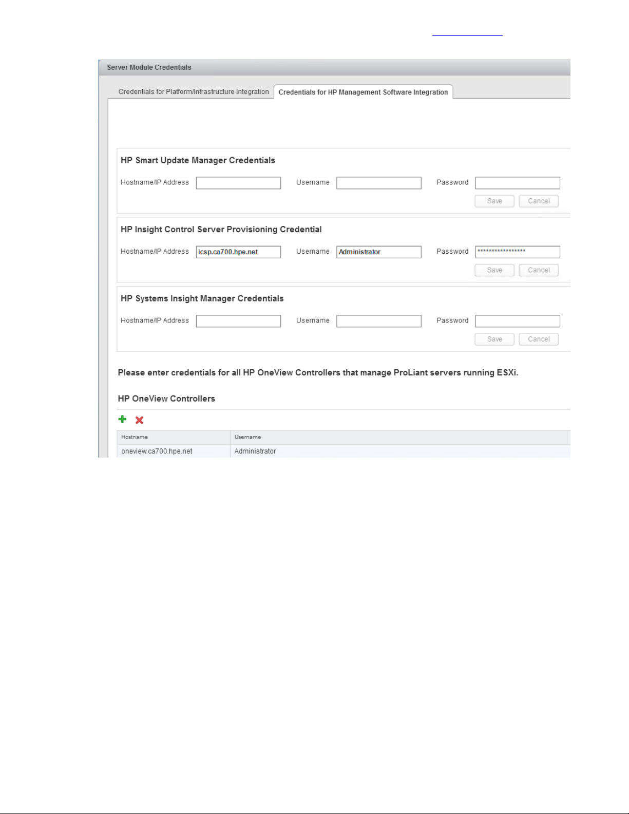
Generate a Self-Signed Certificate
Documentation Feedback
10 Click Save and then click OK after the credentials are successfully saved.
Generate a Self-Signed Certificate
Procedure
1 In the left pane, click HPE Management > Certificate Management.
2 Click Generate self-signed certificate.
3 Add the appropriate information to the certificate and click Generate.
Do not change the common name; this name should be <<ov4vc_fqdn>>.
4 Click Copy to copy the certificate.
5 Keep the certificate in the clipboard.
You will paste the certificate when uploading it to Onboard Administrator.
Upload the Self-Signed Certificate to the Onboard Administrator of Each Enclosure
Procedure
1 Log in to the active Onboard Administrator of the first enclosure.
89Copyright©2017 by Nimble Storage, Inc. All rights reserved.
Page 90

Restart HPE OneView for VMware vCenter Services and Initialize the Plugin
2 In the left pane, navigate to Enclosure Information > Users / Authentication > HP SSO Integration.
3 Click the Certificate Upload tab.
4 Paste the copied certificate to the textbox and click Upload.
5 Repeat the procedure to upload the certificate to each enclosure in the solution through the active Onboard
Administrator.
Note If you are planning to leverage signed certificates, see the HPE OneView for VMware vCenter User
Guide for detailed instructions on how to generate and upload the certificate.
Documentation Feedback
Restart HPE OneView for VMware vCenter Services and Initialize the Plugin
Procedure
1 Log out and close any open VMware vSphere Web Client and vSphere Client for Windows sessions.
2 Using a web browser, navigate to the HPE OneView for VMware vCenter Administration Portal.
3 Choose HPE OneView for VMware vCenter > Settings and click Management VM.
4 Choose Actions > Restart and click Yes, restart.
After HPE OneView for VMware vCenter restarts, the login screen is displayed.
Set Host Network Configuration Preferences
For the OneView for VMware vCenter plugin to be able to call the vSwitches by their custom names during
the grow cluster phase, you must set these vSwitch names.
Procedure
1 In the VMware vSphere Web Client, navigate to Home > HP Management Administration > HP
Management > Host Network Configuration Preferences.
2 Click the Network Preferences tab.
3 Set Custom Name values:
• Deployment_A: Deployment.
• Deployment_B: Deployment.
• FT_A: vmkFT.
• FT_B: vmkFT.
• Mgmt_A: vmkMgmt.
• Mgmt_B: vmkMgmt.
• Mgmt_Set_A: vSwitch0.
• Mgmt_Set_B: vSwitch0.
• VM_Traffic_A: VM_Traffic.
• VM_Traffic_B: VM_Traffic.
• VM_Traffic_Set_A: VM_Traffic_vSwitch.
• VM_Traffic_Set_B: VM_Traffic_vSwitch.
• vMotion_A: vmkvMotion.
• vMotion_B: vmkvMotion.
• vMotion_FT_Set_A: vMotion_FT_vSwitch.
• vMotion_FT_Set_B: vMotion_FT_vSwitch.
This example shows the names that were used in the tested configuration described in this guide; they
are based on the values set up earlier in HPE OneView.
4 Click Save when finished.
90Copyright©2017 by Nimble Storage, Inc. All rights reserved.
Page 91
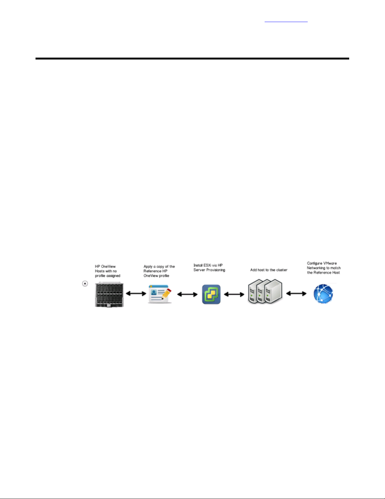
Building the Compute Servers
Documentation Feedback
Building the Compute Servers
Most of the compute cluster build-out configuration steps are automated by Grow Cluster feature of the the
HPE OneView for vCenter plugin.
The first task is to build compute servers through the HPE Grow Cluster enhanced workflow.After the compute
servers are installed, the next task is to configure the network and the storage for these servers.
Build Compute Servers with HPE Grow Cluster
You can build the compute servers with VMware by using the Grow Cluster functionality of HPE OneView
for vCenter. The following example deploys HPE ProLiant BL460c Gen9 servers, but the process is similar
for other compute servers.
Procedure
1 From the Home page of the vSphere Web Client, click Host and Clusters.
2 Right-click <<vcenter_dc_name>> in the left navigation window and click New Cluster. Create a cluster
called <<vcenter_prod_cluster_1_name>> in which to deploy the new hosts. Enable DRS and HA and
leave the defaults. Do not enable EVC or Virtual SAN.
Note Depending on the number of servers and the planned end cluster layout, multiple clusters can be
created.
3 Right-click<<vcenter_prod_cluster_1_name>> and select HP Management Actions > HP GrowCluster
a After the Grow Cluster – Work Flow Selection window appears, select the bottom workflow and click
Next.
b In the Grow Cluster Step 1 window, make the following selections:
a For OS Build Plan, select HPE Grow Cluster – ESXi 6.5 Scripted Install.
b For Reference Server Profile, select CA700 OV4VC BL460c Gen9 Server Profile Template.
c Select the hosts to include in the cluster and click Next.
c In the Grow Cluster Step 2 window, complete the following fields in the Common Host Network
Configuration:
• Netmask: <<mgmt_net_netmask>>.
• DNS Domain: <<mgmt_net_domain_name>>.
• Gateway: <<mgmt_net_gw>>.
• DNS Server: <<mgmt_net_dns1>>.
d After filling in the requested information for all of the blades that are being deployed, click Next.
e Review the summary and click Finish.
f For each blade that you are deploying, fill in the appropriate fields. The following example is for the
first blade:
91Copyright©2017 by Nimble Storage, Inc. All rights reserved.
Page 92

Post Installation: Configure Compute Server for OneView
• NIC0 Static IP Address: <<enclosure_1_blade_bay_1_ip>>.
• ESXi Root Password: <<compute_server_root_password>>.
• (Optional) Hostname: <<enclosure_1_blade_bay_1_hostname>>.
4 It can take one to two hours to deploy the servers, depending on the number of servers being deployed
at once as well as on the current firmware levels. To view a high-level status of the deployment, select
the cluster in vCenter to which you are deploying the blade, and select Monitor Tab > HP Management >
Task.
vCenter does not automatically refresh this screen, so you must manually refresh it for a current status
update.
5 When deployment is complete, the host will be imported into vCenter and its networking configured in a
way similar to that in OneView or in the reference host to which it is pointed.
6 Repeat this procedure for each cluster or set of blades that you deploy.
Documentation Feedback
Post Installation: Configure Compute Server for OneView
Configuring the compute server for OneView is optional, although HPE recommends making the OneView
Server Profile list more user-friendly for the end user.
Procedure
1 Open a web browser and connect to the HPE OneView Web Administration Portal.
2 From the top-left corner, select HP OneView > Server Profiles.
3 For this example, locate blade 1 from enclosure 1 in the list.
Note To make the blade easier to locate, each name is prefixed with the name of the VMware cluster in
which it was deployed.
In the General section of the Overview window for a server profile, the Server hardware field displays
the enclosure and bay for the server profile. The IP address and hostname of the server appear in the
description field.
4 After you locate the blade, hover over General and click Edit.
5 Change the Name to Server_Profile_<<enclosure_1_blade_bay_1_hostname>>.
92Copyright©2017 by Nimble Storage, Inc. All rights reserved.
Page 93

Post Installation: Configure Compute Server Networking
6 Click OK.
Documentation Feedback
Post Installation: Configure Compute Server Networking
After the servers are deployedand the vSwitches are set up, some post-configuration tasks must be manually
completed on the vSwitches and the vKernel adapters. These tasks are not handled by the plugin.
Procedure
1 Launch the vSphere Web Client by opening a web browser to <<vcenter_vm_name>>.
2 Select the first host in the newly created cluster, and click the Configure tab.
3 In the left-side menu, select Virtual Switches from within the Networking section.
4 Select the vSwitch0 virtual switch.
The port groups for vSwitch0 are displayed.
5 Select the vmkDeployment port group and click the red X to remove the port group.
6 Select the vmkmgmt port group and click the edit pencil icon:
a Select Teaming and failover.
b Move all of the adapters to Active Adapters.
c Click OK.
7 Select the vMotion_FT_vSwitch vSwitch and click the edit pencil icon:
a In the Properties section, set the MTU to 9000.
b Click OK.
8 In the left-side menu, select VMkernel Adapters within the Networking section.
9 Select the vmkvMotion VMkernel adapter and click the edit pencil icon:
a On the NIC settings tab, set the MTU to 9000.
b On the IPv4 settings tab, click Use static IPv4 settings.
c Enter the following values:
• IPv4 Address: <<enclosure_1_blade_vmotion_bay_1_ip>>.
• Subnet Mask: <<compute_vmotion_net_netmask>>.
d Click OK.
10 Select the vmkFT VMkernel adapter and click the edit pencil icon:
a On the NIC settings tab, set the MTU to 9000.
b On the IPv4 settings tab, click Use static IPv4 settings.
c Enter the following values:
• IPv4 Address: <<enclosure_1_blade_ft_bay_1_ip>>.
• Subnet Mask: <<compute_ft_net_netmask>>.
d Click OK.
11 Click the globe icon with the green plus sign to Add Host Networking:
a Select Virtual Machine Port Group for a Standard Switch, and click Next.
b Set Select an existing standard switch to vSwitch0, and click Next.
c Set the Network label to Management and VLAN ID to <<mgmt_net_vlan>>, and click Next.
d Review the settings and click Finish.
12 Repeat this procedure for all of the other hosts in the compute cluster.
93Copyright©2017 by Nimble Storage, Inc. All rights reserved.
Page 94

Post Installation: Configure Compute Server for VMware vCenter
Documentation Feedback
Post Installation: Configure Compute Server for VMware vCenter
In order to properly configure vCenter to manage the power of the compute blades, each compute host’s iLO
information must be entered into VMware vCenter.
Procedure
1 Connect to the compute server’sHPE iLO and navigate to Information > System Information > Network
to gather the MAC address of the server iLO.
Note Before you can set the IPMI/iLO power management setting, you must have the MAC address for
the HPE iLO, which is listed in the Adapter 1 – iLO section. In this procedure, it is referred to as
<<mac_address>>.
2 Select the first compute server in the <<vcenter_prod_cluster_1_name>> and navigate to Manage >
Settings > System > Power Management.
3 To the right of IPMI/iLO Settings for Power Management, click Edit.
4 Enter the following information, and then click OK:
• User name: admin
• Password: <<blade_ilo_admin_password>>.
• BMC IP address: << enclosure_1_ebipa_bay1_ip>>.
• BMC MAC address: <<mac_address>>.
5 Repeat this procedure for all of the other compute blades.
Post Installation: Configuring Compute Server for Storage
After the servers are configured in each of the clusters, you can connect the servers to the Nimble Storage
array and provision datastores to them.
Gather the WWN of the Compute Server from OneView
This procedure is necessary at this point only if you have not previously completed this procedure for the
compute host to which you are presenting storage.
Procedure
1 Open a web browser and connect to the HPE OneView Web Administration Portal.
2 From the top left corner, select HP OneView > Server Profiles.
3 Click Server_Profile_<<enclosure_1_blade_bay_1_hostname>>.
4 Click Connections and record the MAC addresses that are associated with the connections to SAN_A
and SAN_B.
The following figure provides an example of the information to capture.
94Copyright©2017 by Nimble Storage, Inc. All rights reserved.
Page 95
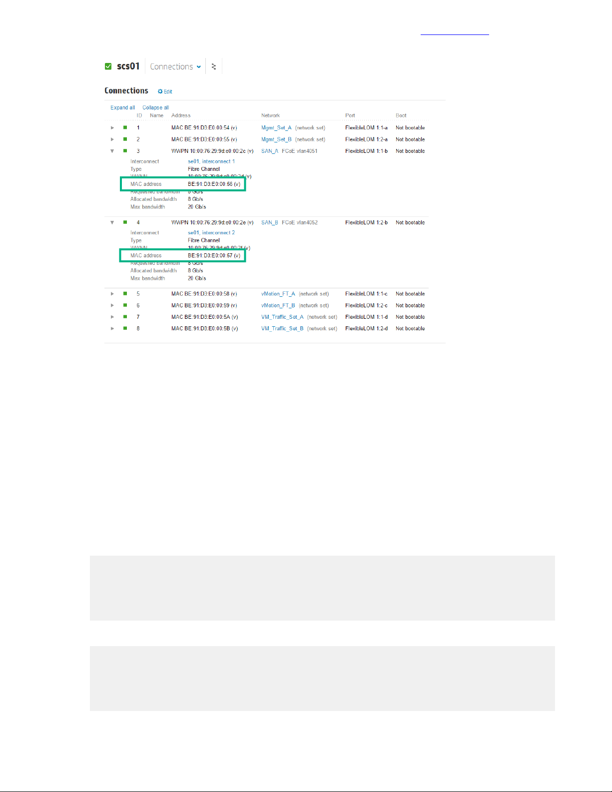
Create and Configure the vFC Interfaces for the Compute Hosts
Documentation Feedback
From this point on, <<san_a_mac_address>> refers to the MAC address for SAN_A, and
<<san_b_mac_address>> refers to the MAC address for SAN_B.
Create and Configure the vFC Interfaces for the Compute Hosts
Procedure
1 Log in to <<net_switch1_mgmt_ip>> through SSH.
2 Run the system-view command to enter system-view mode.
3 Fromsystem-view,create the vFC for the LOM 1 port of the first management server and associate it with
FCoE VSAN A.
Note You can use any vFC identifier you wish in the range of 1 to 1024. The vFC IDs shown in the example
code are the ones used in the verified configuration.
interface vfc 1
description <<enclosure_1_blade_bay_1_hostname>>-LOM1
port trunk vsan <<net_fcoe_vsan_a_id>>
bind interface Bridge-Aggregation 111 mac <<san_a_mac_address>>
quit
4 Create the vFC for the LOM 2 port of the first management server and associate it with FCoE VSAN B.
interface vfc 201
description <<enclosure_1_blade_bay_1_hostname-LOM2
port trunk vsan <<net_fcoe_vsan_b_id>>
bind interface Bridge-Aggregation 112 mac <<san_b_mac_address>>
quit
95Copyright©2017 by Nimble Storage, Inc. All rights reserved.
Page 96

Create Datastores for the Compute Cluster
Documentation Feedback
5 Repeat this procedure for the other compute servers in the configuration. Be sure to use unique vFC
identifiers for each connection.
Create Datastores for the Compute Cluster
Procedure
1 Launch the vSphere Web Client by opening a web browser to <<vcenter_vm_name>>.
2 Right-click the datacenter <<vcenter_dc_name>>.
3 Select Nimble Storage Actions > Create Datastore.
4 Select the Nimble Storage group and click Next.
5 Provide a datastore name and an optional description.
6 Select the compute cluster <<vcenter_prod_cluster_1_name>>.
Note Selecting the compute cluster also selects all of the hosts that are part of the cluster.
7 Click Next.
8 Enter the datastore size, leaving all other options at the default values.
9 Click Next.
10 Select Create New Volume Collection and provide a name for the volume collection.
11 Click Next.
12 Fromthe Schedule Template dropdown menu, selectan appropriate template or create a custom schedule
that meets your snapshot retention requirements.
13 Click Next.
14 Optional: Select IOPS or throughput limits for the datastore.
15 Click Next.
16 Review the settings and click Finish.
17 Repeat these steps as necessary to create additional datastores.
96Copyright©2017 by Nimble Storage, Inc. All rights reserved.
Page 97

Appendixes
Documentation Feedback
Appendixes
Appendix A: Configuration Worksheet
The configuration worksheet lists the variables that are required to complete the tasks in this deployment
guide.Before beginning the deployment of the HPE Converged Architecture 700 with Nimble Storage,ensure
that the configuration worksheet is completed with the correct and validated values. You are free to expand
this configuration worksheet to suit your needs.
Global Networking
ValueVariableDescription
<<mgmt_net_vlan>>Management network VLAN
<<mgmt_net_netmask>>Management network netmask
<<mgmt_net_gw>>Management network gateway
<<mgmt_net_dns1>>Management network DNS server 1
mask
HPE Network Switches
<<mgmt_net_domain_name>>Management network domain name
<<mgmt_net_ntp1>>Management network NTP server 1
<<deployment_net_vlan>>Deployment network VLAN
<<deployment_net_netmask>>Deployment network netmask
<<mgmt_vmotion_net_vlan>>ManagementvMotion network VLAN
<<mgmt_vmotion_net_netmask>>Management vMotion network net-
<<mgmt_ft_net_vlan>>Management FT network VLAN
<<mgmt_ft_net_netmask>>Management FT network netmask
<<compute_vmotion_net_vlan>>Compute vMotion network VLAN
<<compute_vmotion_net_netmask>>Compute vMotion network netmask
<<compute_ft_net_vlan>>Compute FT network VLAN
<<compute_ft_net_netmask>>Compute FT network netmask
<<vm_production_net_1_vlan>>VM production network VLAN
address
ValueVariableDescription
<<net_switch1_mgmt_ip>>Network switch 1 management IP
<<net_switch1_hostname>>Network switch 1 host name
<<net_switch1_mad_ip>>Network switch 1 MAD IP address
<<net_switch2_mad_ip>>Network switch 2 MAD IP address
<<mad_net_netmask>>MAD network netmask
97Copyright©2017 by Nimble Storage, Inc. All rights reserved.
Page 98
Appendix A: Configuration Worksheet
Management Servers
dress
dress
Documentation Feedback
ValueVariableDescription
<<net_switch_admin_password>>Network switch admin password
<<net_switch_domain_id>>Network switch IRF domain ID
ValueVariableDescription
<<mgmt_server_1_ilo_hostname>>Managementserver1 iLO host name
<<mgmt_server_2_ilo_hostname>>Managementserver2 iLO host name
<<mgmt_server_1_ilo_ip>>Management server 1 iLO IP ad-
<<mgmt_server_2_ilo_ip>>Management server 2 iLO IP ad-
<<mgmt_server_ilo_password>>Management servers iLO password
<<mgmt_server_1_hostname>>Management server 1 host name
<<mgmt_server_2_hostname>>Management server 2 host name
address
address
Nimble Storage System
dress
<<mgmt_server_1_fqdn>>Management server 1 FQDN
<<mgmt_server_2_fqdn>>Management server 2 FQDN
<<mgmt_server_1_ip>>Management server 1 IP address
<<mgmt_server_2_ip>>Management server 2 IP address
<<mgmt_server_1_ft_ip>>Management server 1 FT IP address
<<mgmt_server_2_ft_ip>>Management server 2 FT IP address
<<mgmt_server_1_vmotion_ip>>Management server 1 vMotion IP
<<mgmt_server_2_vmotion_ip>>Management server 2 vMotion IP
<<mgmt_server_root_password>>Management server root password
ValueVariableDescription
<<nimble_system_name>>Nimble Storage system name
<<nimble_group_name>>Nimble Storage group name
<<nimble_mgmt_ip>>Nimble Storage management IP ad-
tic IP address
tic IP address
<<nimble_fqdn>>NimbleStorage management FQDN
<<nimble_admin_pwd>>Nimble Storage admin password
<<nimble_CA_diag_IP>>Nimble Storagecontroller A diagnos-
<<nimble_CB_diag_IP>>Nimble Storagecontroller B diagnos-
98Copyright©2017 by Nimble Storage, Inc. All rights reserved.
Page 99

Appendix A: Configuration Worksheet
VMware vCenter
Documentation Feedback
ValueVariableDescription
<<vcenter_vm_name>>vCenter VM name
<<vcenter_mgmt_ip>>vCenter IP address
<<vcenter_hostname>>vCenter host name
<<vcenter_fqdn>>vCenter FQDN
<<vcenter_root_password>>vCenter appliance root password
vCenter administrator password
VM name
IP address
host name
FQDN
root password
<<vcenter_administrator_password>>
<<vcenter_psc_vm_name>>vCenter Platform Services Controller
<<vcenter_psc_mgmt_ip>>vCenter Platform Services Controller
<<vcenter_psc_hostname>>vCenter Platform Services Controller
<<vcenter_psc_fqdn>>vCenter Platform Services Controller
<<vcenter_psc_root_password>>vCenter PlatformServices Controller
<<vcenter_sso_password>>vCenter SSO password
<<vcenter_sso_site_name>>vCenter SSO site name
<<vcenter_dc_name>>vCenter data center name
<<vcenter_mgmt_cluster_name>>vCenter management cluster name
<<vcenter_prod_cluster_1_name>>vCenter production cluster 1 name
Management VM
Management VM administrator
password
address
work IP address
Management VM media user pass-
word
ValueVariableDescription
<<mgmt_vm_name>>Management VM name
<<mgmt_vm_hostname>>Management VM host name
<<mgmt_vm_fqdn>>Management VM FQDN
<<mgmt_vm_administrator_pass-
word>>
<<mgmt_vm_mgmt_ip>>Management VM mgmt network IP
<<mgmt_vm_deployment_ip>>Management VM deployment net-
<<mgmt_vm_media_user_password>>
99Copyright©2017 by Nimble Storage, Inc. All rights reserved.
Page 100
Appendix A: Configuration Worksheet
HPE OneView
Documentation Feedback
ValueVariableDescription
<<oneview_vm_name>>HPE OneView VM name
<<oneview_hostname>>HPE OneView host name
<<oneview_fqdn>>HPE OneView FQDN
HPE OneView administrator password
<<oneview_administrator_password>>
<<oneview_mgmt_ip>>HPE OneView mgmt network IP ad-
dress
<<oneview_mac_start>>HPE OneView MAC address range
start
<<oneview_mac_count>>HPE OneView MAC address count
<<oneview_wwn_start>>HPE OneView WWN address range
start
<<oneview_wwn_count>>HPE OneView WWN address count
<<oneview_serial_start>>HPE OneView serial number range
start
<<oneview_serial_count>>HPE OneView serial number count
<<oneview_readuser_password>>HPE OneView readUser password
HPE OneView for vCenter (OV4VC) Plugin
<<ov4vc_vm_name>>HPE OV4VC VM name
ValueVariableDescription
dress
HPE ICsp
address
<<ov4vc_hostname>>HPE OV4VC host name
<<ov4vc_fqdn>>HPE OV4VC FQDN
<<ov4vc_admin_password>>HPE OV4VC admin password
<<ov4vc_mgmt_ip>>HPE OV4VC mgmt network IP ad-
ValueVariableDescription
<<icsp_vm_name>>HPE ICsp name
<<icsp_hostname>>HPE ICsp host name
<<icsp_fqdn>>HPE ICsp FQDN
<<icsp_administrator_password>>HPE ICsp administrator password
<<icsp_mgmt_ip>>HPE ICsp mgmt network IP address
<<icsp_deployment_ip>>HPE ICsp deployment network IP
<<icsp_dhcp_range_start>>HPE ICsp DHCP range start
100Copyright©2017 by Nimble Storage, Inc. All rights reserved.
 Loading...