

Page 1

HP
P9000 Continuous Access Journal User
Guide
Abstract
This guide explains how to use HP P9000 Continuous Access Journal Software to replicate data between local and remote HP
P9000 disk arrays and to achieve disaster tolerance with maximum application performance. Topics include setting up remote
copy connections, configuring the storage system, creating and monitoring remote copies, recovering from a disaster, and
troubleshooting. The intended audience is a storage system administrator or authorized service provider with independent
knowledge of HP P9000 disk arrays and the HP Remote Web Console.
HP Part Number: AV400-96399
Published: September 2011
Edition: Fifth
Page 2

© Copyright 2010, 2011 Hewlett-Packard Development Company, L.P.
Confidential computer software. Valid license from HP required for possession, use or copying. Consistent with FAR 12.211 and 12.212, Commercial
Computer Software, Computer Software Documentation, and Technical Data for Commercial Items are licensed to the U.S. Government under
vendor's standard commercial license.
The information contained herein is subject to change without notice. The only warranties for HP products and services are set forth in the express
warranty statements accompanying such products and services. Nothing herein should be construed as constituting an additional warranty. HP shall
not be liable for technical or editorial errors or omissions contained herein.
Acknowledgements
Microsoft®, Windows®, Windows® XP, and Windows NT® are U.S. registered trademarks of Microsoft Corporation.
UNIX® is a registered trademark of The Open Group.
Export Requirements
You may not export or re-export this document or any copy or adaptation in violation of export laws or regulations.
Without limiting the foregoing, this document may not be exported, re-exported, transferred or downloaded to or within (or to a national resident
of) countries under U.S. economic embargo, including Cuba, Iran, North Korea, Sudan, and Syria. This list is subject to change.
This document may not be exported, re-exported, transferred, or downloaded to persons or entities listed on the U.S. Department of Commerce
Denied Persons List, Entity List of proliferation concern or on any U.S. Treasury Department Designated Nationals exclusion list, or to parties directly
or indirectly involved in the development or production of nuclear, chemical, biological weapons, or in missile technology programs as specified
in the U.S. Export Administration Regulations (15 CFR 744).
Revision History
DescriptionDateEdition
Applies to microcode version 70-01-01-00/00 or later.October 2010First
Applies to microcode version 70-01-24-00/00 or later.November 2010Second
Applies to microcode version 70-01-62-00/00 or later.January 2011Third
Applies to microcode version 70-02-01-00/00 or later.May 2011Fourth
Applies to microcode version 70-02-5x-00/00 or laterSeptember 2011Fifth
Page 3

Contents
1 Continuous Access Journal overview ............................................................8
Continuous Access Journal software ...........................................................................................8
How Continuous Access Journal works........................................................................................8
Hardware and software components...........................................................................................9
P9500 storage systems.......................................................................................................10
Main and remote control units .......................................................................................10
Pair volumes......................................................................................................................11
Journal volumes.................................................................................................................11
Journals............................................................................................................................11
Data path.........................................................................................................................12
Consistency groups and journals..........................................................................................12
Remote Web Console.........................................................................................................12
RAID Manager..................................................................................................................13
Overview of copy operations...................................................................................................13
Initial copy operation ........................................................................................................13
Update copy operation ......................................................................................................14
Read and Write I/O operations during remote copy operation.....................................................15
S-VOL write option..................................................................................................................15
Difference management...........................................................................................................15
Pair status..............................................................................................................................15
2 Requirements and specifications.................................................................17
System requirements................................................................................................................17
3 Planning volumes and systems....................................................................20
Plan and design workflow .......................................................................................................20
Assessing business requirements for data recovery .....................................................................20
Determining your RPO .......................................................................................................21
Write-workload .....................................................................................................................21
Measuring write-workload...................................................................................................21
Sizing journal volumes ...........................................................................................................22
Determining the required journal volume capacity..................................................................22
Calculating the journal size.................................................................................................23
Planning journals ..............................................................................................................23
Data transfer speed considerations ..........................................................................................23
RAID group configuration ...................................................................................................24
Fibre Channel port configuration..........................................................................................24
Planning journal volumes ........................................................................................................24
Planning pair volumes ............................................................................................................25
Maximum number of pairs allowed .....................................................................................25
Calculating maximum number of pairs.............................................................................25
Priority set for initial copy operations and scheduling order.....................................................26
Disaster recovery considerations ..............................................................................................28
Host failover software ........................................................................................................28
Sharing volumes with Continuous Access Synchronous, other program products..............................28
Planning for Continuous Access Journal with multiple P9500 systems ............................................29
Multiple journals per RAID Manager consistency group .........................................................29
Planning for previous models ...................................................................................................31
Guidelines for preparing systems for Continuous Access Journal ...................................................32
System option modes .........................................................................................................33
4 Planning the data path..............................................................................35
Data path design workflow .....................................................................................................35
Contents 3
Page 4

Sizing bandwidth ..................................................................................................................35
Five sizing strategies ..........................................................................................................35
Calculating bandwidth ......................................................................................................36
Sizing bandwidth for peak write-workload........................................................................36
Sizing bandwidth for peak rolling average write-workload..................................................37
Latency .......................................................................................................................38
Packet loss ...................................................................................................................38
Planning ports for data transfer ................................................................................................39
Determining required number of ports ..................................................................................39
On setting up ports ...........................................................................................................40
Distances supported for Fibre Channel type, number of switches ..................................................40
Supported data path configurations .........................................................................................41
5 Configuration operations...........................................................................43
Configuration workflow ..........................................................................................................43
Define Fibre Channel port attributes .........................................................................................43
Configure storage systems for Continuous Access Journal, define logical paths ...............................45
Configure additional logical paths ...........................................................................................47
Specify number of volumes for initial copy, resync ......................................................................48
Register journal volumes in a journal ........................................................................................50
6 Pair operations.........................................................................................53
Pair operations workflow.........................................................................................................53
Check pair status....................................................................................................................53
Create the initial copy ............................................................................................................53
Split a pair ...........................................................................................................................57
Split a mirror .........................................................................................................................59
Create a point-in-time copy .....................................................................................................59
Restore a pair .......................................................................................................................60
Resynchronize a mirror ...........................................................................................................62
Delete a pair ........................................................................................................................63
Delete pair volumes from a mirror ............................................................................................65
7 Monitoring the system...............................................................................67
Monitor pair activity and status................................................................................................67
Pair status definitions..........................................................................................................67
PSUS types and behaviors..............................................................................................71
PSUE types and behaviors..............................................................................................72
Filtering Information in the List in the Pair Operation window...............................................73
Saving pair status information into a text file.....................................................................74
Monitor copy operations data, I/O .....................................................................................75
Select data to be graphed..............................................................................................76
Manipulate graph, save data..........................................................................................78
Monitor journal (mirror) status...................................................................................................78
Mirror status definitions.......................................................................................................78
Monitor logical path status.......................................................................................................79
History of operations for data volume pairs...........................................................................80
8 Maintaining the system ............................................................................81
Pair maintenance—change the pair-split option .........................................................................81
Journal and mirror maintenance...............................................................................................81
Change Continuous Access Journal options used by journals ..................................................82
Change Continuous Access Journal options used by mirrors ....................................................84
Delete journal volumes from a journal ..................................................................................86
Delete a journal ................................................................................................................87
Logical path maintenance........................................................................................................87
Modify data-transfer time threshold .....................................................................................87
4 Contents
Page 5

Delete logical paths ..........................................................................................................88
Delete the logical path between primary and secondary storage system ...................................89
Manage power-off for systems and network devices ...................................................................89
When power stops unexpectedly.........................................................................................89
When power is removed from primary or secondary system................................................90
When power is removed from network relay devices .........................................................90
Power off storage systems intentionally..................................................................................90
Power off the primary or secondary system.......................................................................90
Power off the primary and secondary systems at the same time...........................................90
Power off network relay devices...........................................................................................91
9 Disaster recovery operations .....................................................................92
Preparing for disaster recovery ................................................................................................92
File and database recovery procedures ....................................................................................92
Switch operations to the secondary site ....................................................................................92
Copy data back to the primary site ..........................................................................................92
Resume normal operations at the primary site ............................................................................93
Disaster recovery when the system consists of multiple primary and secondary storage systems.........94
Recovering the primary site from a failure when the system consists of multiple primary and
secondary storage systems..................................................................................................94
Transferring business tasks to primary site after recovering from primary site failures...................94
Recovery procedures with shared volumes..................................................................................95
Recovery in a 3DC cascade configuration ............................................................................96
Recovering from primary site disaster in 3DC multitarget configuration......................................96
Recovering from primary site failures (when delta resync operation is performed)........................98
Recovering from failures in the primary site and the Continuous Access Synchronous secondary
site................................................................................................................................100
Recovery in a 2DC configuration ......................................................................................101
Resume operations in the primary site ...........................................................................101
Recovery with Business Copy configuration .........................................................................102
10 Troubleshooting....................................................................................103
General troubleshooting........................................................................................................103
Troubleshooting logical paths ................................................................................................104
Troubleshooting suspended pairs ...........................................................................................106
Troubleshooting using Remote Web Console............................................................................107
Error codes .........................................................................................................................108
Troubleshooting using RAID Manager ....................................................................................108
Service information messages (SIMs) ......................................................................................119
Miscellaneous troubleshooting................................................................................................121
Suspension among journals ..............................................................................................121
11 Support and other resources...................................................................122
Contacting HP......................................................................................................................122
Subscription service..........................................................................................................122
Documentation feedback..................................................................................................122
Related information...............................................................................................................122
HP websites....................................................................................................................123
Conventions for storage capacity values..................................................................................123
Typographic conventions.......................................................................................................123
A Sharing Continuous Access Journal volumes ..............................................125
Volume types that can be shared with Continuous Access Journal................................................125
LUN Expansion....................................................................................................................127
Virtual LUN .........................................................................................................................127
Cache Residency..................................................................................................................127
Auto LUN............................................................................................................................127
Contents 5
Page 6

LUN Manager......................................................................................................................128
Thin Provisioning .................................................................................................................128
Data Retention ....................................................................................................................128
Performance Monitor ............................................................................................................129
B Continuous Access Journal configurations with Continuous Access
Synchronous.............................................................................................130
Sharing volumes with Continuous Access Synchronous...............................................................130
3DC cascade configuration ..................................................................................................131
Prerequisite information for 3DC cascade ...........................................................................131
Procedure for setting up 3DC cascade ...............................................................................132
3DC multitarget configuration ................................................................................................132
Prerequisite information for 3DC multitarget ........................................................................133
Procedure for setting up 3DC multitarget.............................................................................133
Delta resync configuration .....................................................................................................134
Prerequisite information for creating the delta resync pair .....................................................135
Prerequisite information for performing the delta resync operation..........................................135
Creating a delta resync pair .............................................................................................137
Configuring the delta resync operation environment to support remote command devices..........137
Establish immediate communications ............................................................................137
Assign mirrors to remote command devices ....................................................................138
Release a remote command device which is assigned to a mirror......................................140
Perform the delta resync operation .....................................................................................140
2 data center configuration ...................................................................................................140
Prerequisite information for 2DC configuration ....................................................................141
Specifications and restrictions for Continuous Access Journal pair operations.......................141
Specifications and restrictions for Continuous Access Synchronous pair operations...............142
Procedure for 2DC setup ..................................................................................................142
C Continuous Access Journal configurations with Business Copy......................143
Overview............................................................................................................................143
Configurations with Business Copy primary volumes .................................................................143
Configurations with Business Copy secondary volumes .............................................................145
Pair status and data currency.................................................................................................145
D Continuous Access Journal configurations with External Storage Access
Manager..................................................................................................147
Overview............................................................................................................................147
Configurations with Continuous Access Journal secondary volumes ............................................147
E Continuous Access Journal GUI reference...................................................148
Journal Operation window ....................................................................................................148
Journal Detail window ..........................................................................................................151
Change Journal Option dialog box ........................................................................................154
Change Mirror Option dialog box .........................................................................................154
Edit Journal Volumes dialog box.............................................................................................155
Pair Operation window ........................................................................................................157
Detailed Information dialog box ........................................................................................160
Paircreate dialog box ......................................................................................................163
Pairsplit-r dialog box .......................................................................................................165
Pairresync dialog box ......................................................................................................166
Pairsplit-S dialog box .......................................................................................................167
Change Pair Option dialog box.........................................................................................168
Display Filter dialog box ..................................................................................................169
DKC Operation window .......................................................................................................170
Remote Systems Information ..............................................................................................171
6 Contents
Page 7

Logical Path Information....................................................................................................172
Port Information for the local system....................................................................................173
DKC Status dialog box ....................................................................................................173
Add DKC dialog box .......................................................................................................175
DKC Option dialog box ...................................................................................................176
Usage Monitor window ........................................................................................................177
History window ...................................................................................................................177
Operations in History window ..........................................................................................179
History window notes.......................................................................................................180
Export operations history .................................................................................................181
Optional Operation window .................................................................................................181
Glossary..................................................................................................183
Index.......................................................................................................185
Contents 7
Page 8
1 Continuous Access Journal overview
Unless otherwise specified, the term P9000 in this guide refers to the following disk array:
• P9500 Disk Array
The GUI illustrations in this guide were created using a Windows computer with the Internet Explorer
browser. Actual windows may differ depending on the operating system and browser used. GUI
contents also vary with licensed program products, storage system models, and firmware versions.
With Continuous Access Journal (Cnt Ac-J), you create and maintain a remote copy of a data
volume on a P9500 system. The remote copy is a block-for-block copy of the local storage volume.
Remote data is consistent with local data and therefore available for recovery of the local volume
should the need arise.
This guide provides instructions for planning, implementing, operating, maintaining, and
troubleshooting a Continuous Access Journal system.
The following configurations described in this document are unsupported in version 70-01-2x:
• Three data center (3DC) multitarget configuration
• Three data center (3DC) cascade configuration
• Three data center (3DC) configuration using the delta resync function
• Configuration using multiple primary and secondary storage systems
Continuous Access Journal software
With Continuous Access Journal, application data is copied to a secondary P9500 system at a
remote location. Continuous Access Journal is designed to support a remote site hundreds and
even thousands of miles from the local site, making recovery from region-wide disasters possible.
This guide provides scenarios and procedures for disaster recovery from multiple sites.
When a pair is created, the remote system will contain an asynchronous, block-for-block copy of
the local storage volume. Impact on host I/O and the primary storage system is limited, since
updates sent to the primary volume are also copied to a local journal volume. The remote system
“pulls” data from the journal volume across the communication link to the backup-volume. The
primary system is free to perform its role as a transaction processing resource rather than as
replication engine.
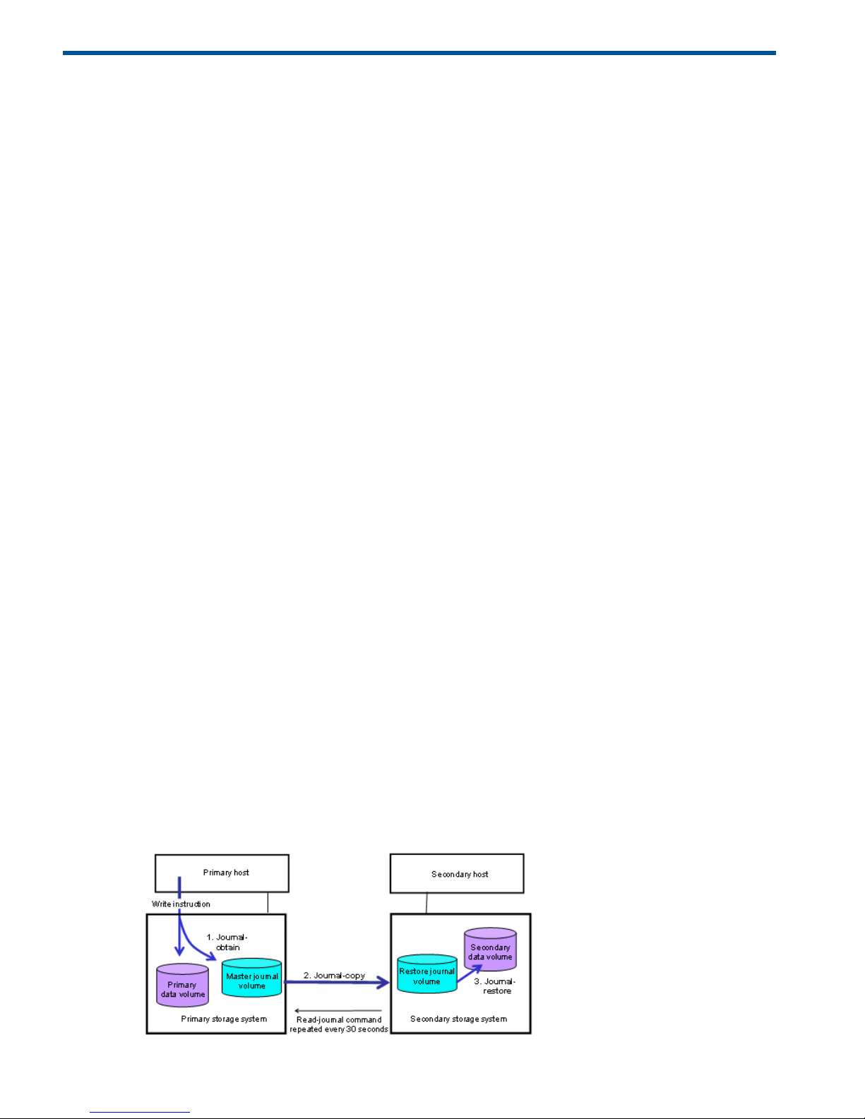
How Continuous Access Journal works
With Continuous Access Journal, you enable a data back up from a primary volume (P-VOL) on
the local system to a secondary volume (S-VOL) on a remote system. Continuous Access Journal
operations are performed sequentially as shown below.
Figure 1 Basic sequence in Continuous Access Journal operations
8 Continuous Access Journal overview
Page 9

Remote replication occurs using journal volumes on the local and remote systems.
• The journal on the local system is the “master journal”.
• The journal on the remote system is the “restore journal”.
Replication occurs in the following sequence:
• Journal obtain - When the host sends an update to the primary volume, the system’s
journal-obtain function triggers a copy of the update data to the master journal volume.
◦ The host assigns write-sequence numbers to the data sent to the journal.
◦ Write-sequence numbers and other metadata attached to journal data insure consistency
with the data in the primary volume.
• Journal copy - data is copied from the master journal to the restore journal.
If the master journal has data, the primary system transfers it to the restore journal. When
data transfer is complete, master journal data is discarded.
◦
◦ Data copy to the restore journal is initiated by the read-journal command issued by the
remote system.
◦ Data copy occurs on a continual basis unless there is no data in the local journal. On
storage system, journal reading operations are performed just after finished the former
read operation.
• Journal-restore - the secondary volume is updated with changed data from the restore journal.
Data is copied to the secondary volume according to the write sequence numbers, insuring
data consistency.
◦
◦ When journal-restore is completed, the data in the restore journal is discarded.
NOTE:
• In the configuration of Continuous Access Journal, the updating of data volumes and the
creating of journal data are processed. The performance of data volumes replicated with
Continuous Access Journal will be slightly lower than that of unreplicated data volumes.
• The primary storage system does not remove the target journal data from its master journal
volume until it receives the sequence numbers of the restored journal that is given to the read
journal command from the secondary storage system. This is true even if the primary storage
system and secondary storage system are connected using a channel extender product.
Hardware and software components
A typical configuration consists of a P9500 or externally attached system on both local and remote
sites, a host or hosts connected to the systems, Continuous Access Journal software on both systems,
data path connections, and interface tools for configuring and managing Continuous Access
Journal.
• The local and remote P9500 systems are connected using dedicated fibre channel data paths,
which can include fibre channel switches. Data paths are routed from the fibre channel ports
on primary system to the ports on the secondary system.
• The host is connected to the P9500 using a fibre channel target port.
• Remote Web Console is connected via a management LAN.
Hardware and software components 9
Page 10
A Continuous Access Journal system consists of the following:
• P-VOLs and S-VOLs on the local and remote P9500
• Master and restore journal volumes on the local and remote P9500
• Master and restore journals on the local and remote P9500
The master journal consists of the primary volume(s) and master journal volume(s).◦
◦ The restore journal consists of the secondary volume(s) and restore journal volume(s).
Management software consists of:
• Remote Web Console graphical user interface (GUI)
• RAID Manager
NOTE:
• Continuous Access Journal Z processing continues uninterrupted if the SVP reboots or even if
the SVP fails.
• Continuous Access Journal Z does not support operations in which one P-VOL is copied to
more than one S-VOL, or more than one P-VOL is copied to one S-VOL.
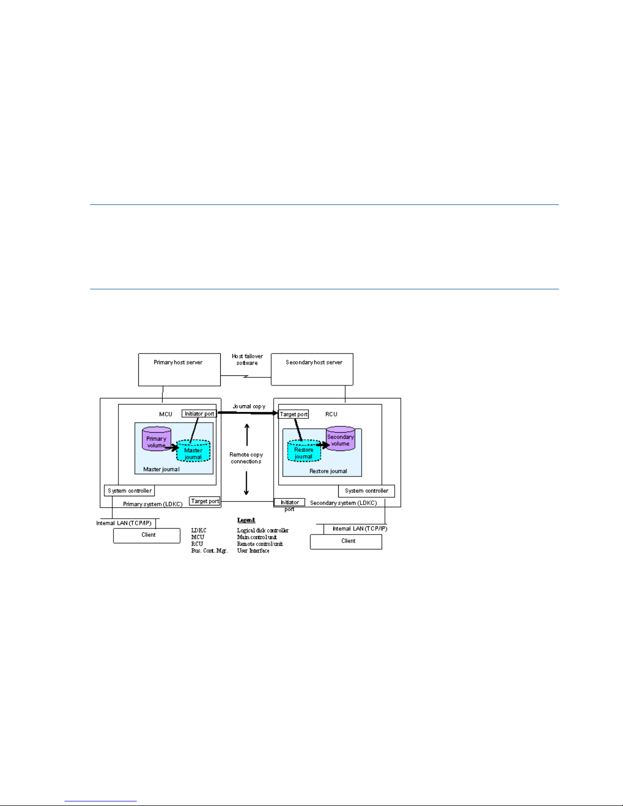
Continuous Access Journal components are illustrated in the following figure and described in
greater detail in the following sections.
Figure 2 Continuous Access Journal components
P9500 storage systems
Continuous Access Journal is operated using two P9500 storage systems, one at the primary and
one at secondary sites. The primary system consists of the main control unit (MCU) and the SVP .
The secondary system consists of the remote control unit (RCU) and the SVP.
• The primary system communicates with the secondary system over dedicated fibre channel
remote copy connections.
• The P9500 system can function simultaneously as a primary and secondary system.
Main and remote control units
The primary and secondary systems are often referred to as the MCU (primary system) and RCU
(secondary system). MCU is the main control unit, RCU is the remote control unit.
10 Continuous Access Journal overview
Page 11

MCUs control the primary storage volume (P-VOL) and the following operations:
• Host I/O operations to the P-VOL
• Master journal operations
• Initial copy and update copy operations between the P-VOL and secondary volume (S-VOL).
RCUs control the secondary storage volume (S-VOL) and the following operations:
• Issue read-journal commands to the MCU.
• Manage the copying of journal data from master to restore journal.
• Manage the copying of restore journal data to S-VOL.
• Assist in managing pair status and configuration (for example, rejects write I/Os to the S-VOLs).
Pair volumes
Original data is stored in the P-VOL and the remote copy is stored in the S-VOL. The pair can be
paired, split, re-synchronized, and returned to the simplex state. When synchronized, the volumes
are paired; when split, new data sent is to the P-VOL but held from the S-VOL. When
re-synchronized, changed data is copied to the S-VOL. When a disaster occurs, production
operations can be transferred to the S-VOL. When the primary site is functional again, operations
and data can be transferred and copied back to the P-VOL.
The P-VOL remains available to the host for read and write I/O operations. The secondary system
rejects write I/Os for the S-VOL, unless the write-enable option is specified for the S-VOL. Then,
write I/O is allowed to the S-VOL while the pair is split. In this instance, S-VOL and P-VOL track
maps keep track of differential data and use it to re-synchronize the pair.
Journal volumes
Journal volumes are required on the primary and secondary systems.
• Updates to the P-VOL are copied to the master journal volume in the primary system. See the
illustration in “Journals” (page 11).
• Master journal data is copied to the restore journal volume on the secondary system.
• Journal volumes can have different volume sizes and different RAID configurations.
• Journal data is stored sequentially and separately into each journal volume in the same journal.
For information on planning journal volumes, see “Sizing journal volumes ” (page 22) .
NOTE: If a path is defined from a host to a volume, you cannot register the volume as a journal
volume.
Journals
Journals help you manage data consistency between multiple P-VOLs and S-VOLs. A journal consists
of two or more data volumes and journal volumes.
You use journals to create multiple pairs and to split, resync, and release multiple pairs. Journals
are required on the primary and secondary systems.
Each data volume and its associated journal volume reside in the same journal. This is illustrated
below.
• The master journal contains master journal volumes and is associated with the P-VOL.
• The restore journal contains restore journal volumes and is associated with the S-VOL.
Each pair relationship between journals is called a "Mirror". A Mirror ID identifies a pair relationship
between journals. When the pair is created, it is assigned a mirror ID.
Hardware and software components 11
Page 12
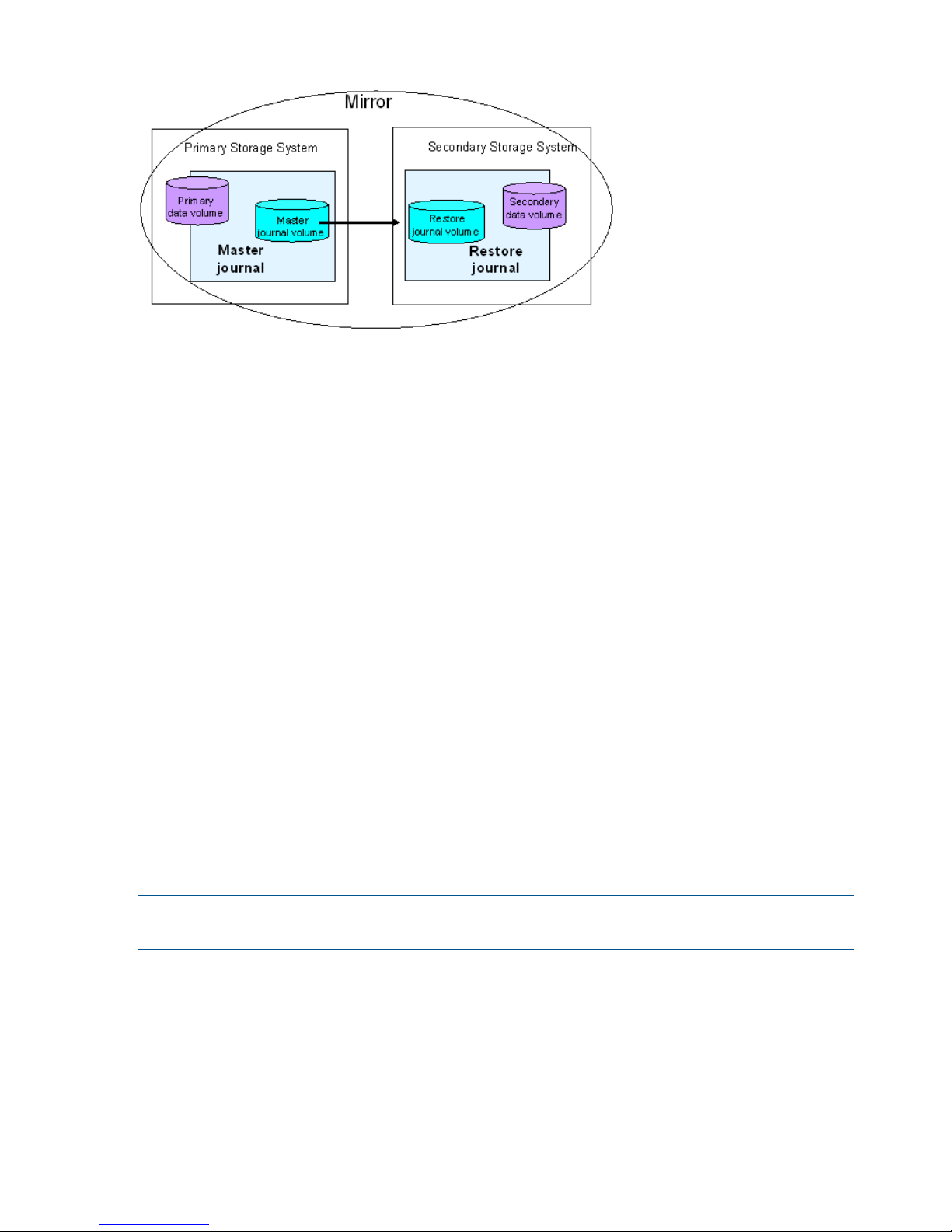
Figure 3 Journals
Data path
The physical transmission link between the local and remote systems is called the data path.
Continuous Access Journal commands and data are transmitted through the fibre channel data
path and switches. The data path is connected to the primary and secondary systems through two
types of Fibre Channel ports, Initiator and RCU Target ports.
One data path connection is required for Continuous Access Journal. HP recommends two or more
independent connections to provide hardware redundancy. A maximum of eight paths can be
used.
For more information, see “Planning the data path” (page 35).
Consistency groups and journals
A consistency group is a group of pairs in the same primary and secondary systems. Consistency
groups are defined using RAID Manager. When you issue a pair command, the copy operation
is executed on all pairs in the group with the writing order guaranteed between a primary volume
and the secondary volume. The pair status changes at the same time, depending on group options.
Continuous Access Journal can use RAID Manager consistency group numbers. Therefore, you can
create a Continuous Access Journal pair using the consistency group numbers from RAID Manager.
In Continuous Access Journal operations, the consistency group numbers that are specified from
RAID Manager are assigned to journal numbers.
The specification of consistency group number storage system has total 256 consistency groups
(numbered 0 to 255) for the P-VOL and S-VOL (No. 0 to 127 are assigned).
Journals are used in Continuous Access Journal to guarantee data consistency across multiple pairs.
For Continuous Access Journal operations, it is best practice to make consistency group numbers
and journal numbers the same, if possible.
NOTE: The consistency group number of the primary and secondary data volumes to be paired
must be same.
Remote Web Console
Remote Web Console communicates with the SVP of each storage system over defined TCP/IP
connections.
• Remote Web Console must be LAN-attached to the primary system
• Remote Web Console is not required on the secondary system; however having it available
allows you to change Continuous Access Journal parameters and access the Continuous Access
Journal S-VOL for maintenance or disaster recovery.
12 Continuous Access Journal overview
Page 13

NOTE:
• Administrator or Continuous Access Journal write access to the Remote Web Console Java
applet program is required to perform these operations. Users without Administrator or
Continuous Access Journal write access can only view Continuous Access Journal information.
• If the RAID Manager computer is not installed, contact your HP account team for information
on Continuous Access Journal configuration services.
RAID Manager
RAID Manager can be used to perform the same operations as the Remote Web Console GUI.
The operations can be run with RAID Manager using scripts.
Overview of copy operations
The following sections describe initial and update copy operations including the underlying
operations, such as journal processing and differential data management.
Initial copy operation
The initial copy is executed when the primary storage system copies all the data in sequence in
the P-VOL directly to the S-VOL. Though journal volumes are not used during the initial copy, the
copy data in this operation is referred to as “base journal data”.
• Creating pairs independently of journal activity results in the base journal data being copied
to the respective S-VOLs one-at-a-time. This extends the time required for multiple initial copies.
• An initial copy operation can be performed to establish the Continuous Access Journal pair
relationship — with no data copied between the volumes. This can be done when data in the
P-VOLs and S-VOLs are the same.
• A volume pair can also be created using a Continuous Access Synchronous initial copy
operation. See “Planning pair volumes ” (page 25) for more information.
Overview of copy operations 13
Page 14

NOTE:
• If you manipulate volumes (not journals) to create or resynchronize two or more data volume
pairs within the same journal, the base journal data for these pairs will be stored in the restore
journal. Therefore, the operation for restoring the latter base journal will be delayed.
• You can specify None as the copy mode for initial copy operations. If the None is specified,
initial copy operations are not performed. Therefore, if you specify None, you are responsible
for ensuring that the data in the primary and secondary data volume is exactly the same.
• You may create a Continuous Access Journal data volume pair by using Continuous Access
Synchronous initial copy. In that case, set the appropriate system option that is system option
474, on both primary and secondary storage system. In addition, the script, which is written
especially for this operation, is also required. If you use the script without setting the system
option on the secondary storage system, the storage system recognizes the Continuous Access
Synchronous R-VOL as the Continuous Access Journal S-VOL, and the SSB log (SSB=CBED) is
generated in the secondary storage system. In this case, the command to create the pair is
rejected. The script is executed normally when you use the script without setting the system
option on the primary storage system, however, note that the processing speed of the
Continuous Access Synchronous initial copy slows down if there is the update I/O during the
operation.
• If you delete all Continuous Access Journal data volume pairs in the journal and then create
a Continuous Access Journal data volume pair, wait for one or more minutes after deleting
pairs.
• When an RCU is shared with multiple MCUs, perform the pair resume operation after system
option mode 593 is set to available if you resume 1025 or more pairs from multiple MCUs
(range: mirror) at the same time. Pair resume operations may fail if system option mode 593
is not available.
Update copy operation
When a host produces new or changed information, the following occurs in the primary storage
system:
• The update is written to the P-VOL.
• The update is copied to the master journal along with metadata that includes sequence and
other consistency information.
Replication to the secondary system is prompted by the read-journal command. This is issued
by the remote system independently of host I/O activity. Read-journal commands are repeated
every 30 seconds. At this time, the following occurs:
◦ Any data that exists in the master journal on the primary side is sent to the restore journal
on the remote system.
◦ The updated data is then copied to the S-VOL.
◦ Data is updated to the remote system continuously until there is no more data in the master
journal.
◦ Journal data on the primary and secondary systems is discarded when data consistency
is established in the copy.
NOTE: Journal data is transferred using special I/O operations initiated by the secondary
system (RCU), called RIO (remote I/O). RIO provides the most efficient type of data transfer.
Make sure that your channel extenders are capable of supporting RIO. Contact HP Technical
Support for more information.
If an update copy operation fails, the remote system suspends the affected pair or all Continuous
Access Synchronous pairs in the journal. This is dependent on the type of failure. The suspended
14 Continuous Access Journal overview
Page 15

pair or journal returns to Paired status when the primary and secondary storage systems are
re-synchronized.
Read and Write I/O operations during remote copy operation
The primary system reads from the P-VOL when it receives a read I/O. If the read fails, the
redundancy provided by RAID-1 or RAID-5 technology recovers the failure. The primary system
does not read the S-VOL for recovery.
When a primary system receives a write I/O for a P-VOL in PAIR status, the system performs the
update copy operation, as well as writing to the P-VOL. The write operation completes independently
of the update copy operations on the S-VOL.
The secondary system updates the S-VOL according to the write sequence number in the journal
data. This maintains data consistency between P-VOL and S-VOL.
If the P-VOL write operation fails, the primary system reports a unit check and does not create the
journal data for this operation. If the update copy operation fails, the secondary system suspends
either the affected pair or all Continuous Access Journal pairs in the journal, depending on the
type of failure. When the suspended pair or journal is resumed, the primary and secondary systems
negotiate the resynchronization of the pair(s).
During normal Continuous Access Journal operations, the secondary system does not allow S-VOLs
to be online (mounted). Therefore, hosts cannot read from or write to S-VOLs. The S-VOL write
enable option allows write access to a secondary data volume while the pair is split. The option
is only available when you split the pair from the primary system.
To reduce the overhead associated with these remote copy activities and maximize data transfer,
the P9500 storage system utilizes a special write command, which is allowed only for Continuous
Access Journal initial and update copy operations. This command transfers the control parameters
and the FBA format data for consecutive updated records in a track using a single write operation.
The special Continuous Access Journal write command eliminates the overhead required for
performing FBA to CKD and CKD to FBA conversions.
Remember that the host cannot write data to the Continuous Access Journal P-VOL belonging to
the journal that was registered when 2DC Cascade is set to Enable in the Edit Journal Volume dialog
box.
S-VOL write option
When a pair is split, you can set an option that will allow write I/O to the S-VOL. The S-VOL write
option is selected during the Suspend Pair operation When performing the operation from the
primary system. When you resynchronize a split pair whose S-VOL is write-enabled, the secondary
system sends the S-VOL track bitmap to the primary system, which merges the P-VOL and S-VOL
bitmaps to determine which tracks are out of sync. This ensures proper resynchronization of the
pair.
Difference management
Differential data (updates during split or suspension) between the P-VOL and S-VOL is stored in a
track bitmap. When a split/suspended pair is resumed, the primary system merges the P-VOL and
S-VOL bitmaps, and the differential data is copied to the S-VOL.
The number of bitmap areas affects the maximum possible number of pairs that can be created in
the storage system.
Pair status
Every pair operation results in a change in pair status. You should monitor pair status to insure
that an operation completed successfully. Also, pairs must have a specific status in order for specific
operations to be executed.
Read and Write I/O operations during remote copy operation 15
Page 16

The following provides a brief description of the pair statuses. For complete details, see “Pair status
definitions” (page 67) .
• SMPL: A volume that is not assigned to a pair is in Simplex status, SMPL.
• COPY: When copy processing is started, the primary system changes the status of the P-VOL
and S-VOL to COPY.
• PAIR: When the initial copy processing is complete, the primary system changes the status of
both data volumes to PAIR.
• PSUE: When a pair is suspended due to an error condition, the primary system changes the
P-VOL and S-VOL status to PSUE (if the path status is normal).
• PSUS:
◦ When a pair is split by the user (pairsplit-r), the primary or secondary system changes
the status of the P-VOL and S-VOL to PSUS (if the path status is normal).
◦ If a pair is split from the secondary system, it changes the S-VOL status to PSUS. The
primary system detects the split (if path status is normal) and changes the P-VOL status to
PSUS.
16 Continuous Access Journal overview
Page 17

2 Requirements and specifications
This chapter provides system requirements for Continuous Access Journal.
System requirements
Continuous Access Journal operations are performed between the host(s) and the primary and
secondary storage systems containing the P-VOLs and S-VOLs, using the data path.
General requirements for the Continuous Access Journal components are listed below.
Table 1 General system requirements
RequirementItem
Two—one at the local site, one at the remote site. Also, any combination of the
following can be used with Continuous Access Journal:
Number of P9500 systems
• Four on primary side
• Four on secondary side
Continuous Access Journal
• Must be installed on primary and secondary P9500 storage systems.
• License keys required.
• On secondary systems, Continuous Access Journal can coexist with Continuous
Access Journal Z.
• When a virtual volume of Thin Provisioning (V-VOL) is used for a Continuous
Access Journal P-VOL or S-VOL, the capacity of the allocated pages for the
V-VOL is included in the licensed capacity of Continuous Access Journal. If the
actual licensed capacity exceeds the available licensed capacity, you may use
Continuous Access Journal for 30 days. After 30 days, Continuous Access
Journal pairs may only be split or released.
Other licenses required
• Continuous Access Synchronous is required, whether or not Continuous Access
Journal shares volumes with Continuous Access Synchronous).
• Continuous Access Journal 3DC & 4x4 Open MF in the following Continuous
Access Journal configurations:
- When running a 3DC system
- When performing Continuous Access Journal operations on multiple primary
and secondary storage systems
The following program products can be used:
• Remote Web Console
Administrator or Continuous Access Journal write access is required; otherwise
read access is provided with Remote Web Console.
• RAID Manager
Interfaces
UNIX based and PC-server platforms:Supported host platforms
• HP-UX 11.0 and 11i
• Oracle Solaris 9
• Windows 2000
• Windows 2003
• IBM AIX 5.1
Contact HP Technical Support for the latest information.
Fibre channel.Data path
System requirements 17
Page 18

Table 1 General system requirements (continued)
RequirementItem
Volumes
• P-VOL and S-VOL must be equal in size.
• P-VOL and S-VOL must be of same emulation type.
• The maximum volume size of P-VOL and S-VOL is 4,194,304.000MB
(8,589,934,592Block). However, when XP12000 Disk Array or XP10000 Disk
Array is used as the primary or secondary storage system, the maximum volume
size is 2,949,120.00MB (6,039,797,760Block).
• The minimum volume size of P-VOL and S-VOL is 48.000MB (96,000Block).
• One Continuous Access Journal P-VOL may be copied to one S-VOL only.
• When Continuous Access Synchronous is cascaded with Continuous Access
Journal, a data volume may be copied to multiple data centers.
Limited per P9500 system. See “Maximum number of pairs allowed ” (page 25).Maximum number of pairs
Continuous Access Journal operations between P9500 and previous models are
supported.
Supported previous models
See “Planning for previous models ” (page 31)
RAID1, RAID5, RAID6 are supported for the data volumes and journal volumes.
RAID1, RAID5, and RAID6 can coexist in the same journal.
Supported RAID groups
Virtual LUN volume is supported.Supported volumes
• Can be used for data and journal volumes.
• S-VOL capacity must equal P-VOL capacity.
Cache Residency volume is supported as follows:
• Data volume: yes
• Journal volume: no
LUN Expansion volume is supported.
Must be operable for primary and secondary systems to insure pair creation success.
The remote system cache should be configured to adequately support Continuous
Cache and Nonvolatile Storage
(NVS)
Access Journal remote-copy workloads, as well as local workload activity. In
general, cache capacity should be increased 25 percent for Continuous Access
Journal. Also, an additional GB should be added for each journal on the system.
Required for disaster recovery.Host failover software
18 Requirements and specifications
Page 19

Table 1 General system requirements (continued)
RequirementItem
RAID Manager consistency groups
when multiple primary and
secondary storage system
• Up to four journals can be registered in one RAID Manager consistency group.
If there are four storage systems, you must create one journal for each storage
system.
• Up to 8,192 pairs, the total number of pairs registered in the journals in one
RAID Manager consistency group can be registered. However, it is
recommended that you register only up to 4,096 pairs.
Journals
• Max. number: 256 (0 to 255) per storage system
• Recommended number: Up to 16
• Max. number of journal volumes: 64 per journal
• Max. number of data volumes: 8,192 per journal
• Journal numbers of master and restore journals that are paired can be different.
• A data volume and associated journal volume can belong to only one journal.
• Data volumes and journal volumes that belong to different controllers cannot
be in the same journal.
• The number of journal volumes in the master journal does not have to be equal
to the number of volumes in the restore journal.
• The P-VOLs and S-VOLs in a journal must be located in one physical primary
system and one physical secondary system (1-to-1 requirement).
• Each pair relationship in a journal is called a "Mirror". Each pair is assigned
a Mirror ID. Max. number of Mirror IDs = 4 (0 to 3).
• When Continuous Access Journal co-exists with Continuous Access Journal Z
in the same storage system, individual journals must be dedicated either to one
or the other, but not both.
• Master and restore journals are managed according to the journal number.
NOTE: The capacity of journal volume is not included in the accounting capacity.
NOTE: Continuous Access Journal can co-exist with Continuous Access Journal Z in the same
storage system.
System requirements 19
Page 20

3 Planning volumes and systems
This chapter provides information and instructions for planning Continuous Access Journal volumes,
P9500 systems, and other important requirements and restrictions.
Plan and design workflow
Planning the Continuous Access Journal system is tied to your organization’s business requirements
and production system workload. This means defining business requirements for disaster downtime
and measuring the amount of changed data your system produces over time. With this information,
you can calculate the size that journal volumes must be and the amount of bandwidth required to
transfer update data over the data path network.
The plan and design workflow consists of the following:
• Assess your organization’s business requirements to determine recovery requirements.
• Measure your host application’s write-workload in MB per second and write-input/output per
second (IOPS) to begin matching actual data loads with the future Continuous Access Journal
system.
• Use collected data along with your organization’s recovery point objective (RPO) to size
Continuous Access Journal journal volumes. Journal volumes must have enough capacity to
hold accumulating data over extended periods.
The sizing of journal volumes can be influenced by the amount of bandwidth you settle on.
Both efforts are interrelated. You may actually adjust journal volume size in conjunction with
bandwidth to fit the organization’s needs.
• Use IOPS to determine data transfer speed into and out of the journal volumes. Data transfer
speed is determined by the number of Fibre Channel ports you assign to Continuous Access
Journal, and by RAID group configuration. You need to know port transfer capacity and the
number of ports that your workload data will require.
• Use collected workload data to size bandwidth for the fibre channel data path. As mentioned,
bandwidth and journal volume sizing, along with data transfer speed, are interrelated.
Bandwidth may be adjusted in conjunction with the journal volume capacity and data transfer
speed you plan to implement.
• Design the data path network configuration. This involves understanding supported
configurations, the need for fibre channel switches, the number of ports your data transfer
requirements call for.
• Plan data volumes (primary and secondary volumes). This involves understanding the sizing
of P-VOL and S-VOL, RAID group considerations, and so on.
• Understand operating system requirements for data and journal volumes.
• Adjust cache memory capacity for Continuous Access Journal.
Some tasks will be handled by HP personnel. The planning information you need to address is
provided in the following sections.
Assessing business requirements for data recovery
In a Continuous Access Journal system, when the data path continues to transfer changed data to
the remote site, journals remain fairly empty. However, if a path failure or a prolonged spike in
write-data that is greater than bandwidth occurs, data is stored in the journal. Changed data that
is no longer moving to the remote system builds up in the master journal.
20 Planning volumes and systems
Page 21

To ensure that journals can hold the amount of data that could accumulate, they must be sized
according to the following:
• The maximum amount of time that journals could accumulate data. You develop this information
by determining your operation’s recovery point objective (RPO).
• The amount of changed data that your application generates. This is done by measuring
write-workload.
Determining your RPO
Your operation’s recovery point is the maximum time that can pass after a failure or disaster occurs
before data loss is greater than the operation can survive.
For example, if the operation can survive one hour’s worth of lost data, and a disaster occurs at
10:00 am, then the system must be corrected by 11 a.m.
In regards to journal sizing, the journal must have the capacity to hold the data that could
accumulated in one hour. If RPO is 4 hours, then the journal must be sized to hold 4-hours' worth
of accumulating data.
To assess RPO, the host application’s write-workload must be known.
With write-workload and IOPS, you or your organization’s decision-makers can analyze the number
of transactions write-workload represents, determine the number of transactions the operation could
loose and still remain viable, determine the amount of time required to recover lost data from log
files or key it in, and so on. The result is your RPO.
Write-workload
Write-workload is the amount of data that changes in your production system in MB per second.
As you will see, write-workload varies. according to the time of day, week, month, quarter. That
is why workload is measured over an extended period.
With the measurement data, you can calculate workload averages, locate peak workload, and
calculate peak rolling averages, which show an elevated average. With one of these base data
you will calculate the amount of data that accumulates over your RPO time, for example, 2 hours.
This will be a base capacity for your journal volumes or represent a base amount of bandwidth
your system requires.
Whether you select average, rolling average, or peak workload is based on the amount of
bandwidth you will provide the data path (which is also determined by write-workload). Bandwidth
and journal volume capacity work together and depend on your strategy for protecting data.
Measuring write-workload
Workload data is collected using Performance Monitor or your operating system’s
performance-monitoring feature. The number of read/write transactions, or input/output per second
(IOPS), is also collected by the software. You will use IOPS to set up a proper data transfer speed,
which you insure through RAID group configuration and by establishing the number of Fibre Channel
ports your Continuous Access Journal system requires. Each RAID group has a maximum transaction
throughput; the ports and their microprocessors have an IOPS threshold.
Workload and IOPS collection is best performed during the busiest time of month, quarter, and
year. This helps you to collect data that shows your system’s actual workloads during high peaks
and spikes, when more data is changing, and when the demands on the system are greatest.
Collecting data over these periods insures that the Continuous Access Journal design you develop
will support your system in all workload levels.
Write-workload 21
Page 22

To measure write-workload and IOPS
1. Using your performance monitoring software, collect the following:
• Disk-write bytes-per-second (MB/s) for every physical volume that will be replicated.
• Data should be collected over a 3 or 4-week period to cover a normal, full business cycle.
• Data should be collected at 5 minute intervals. If you use averages, shorter intervals
provide more accuracy.
2. At the end of the collection period, convert the data to MB/second, if needed, and import
into a spreadsheet tool.
Sizing journal volumes
Determining the required journal volume capacity
The following factors determine the required journal volume capacity:
• The period of time during which data transfer can occur between hosts and the primary storage
system when there is a temporary increase in transferred data or a communication path fails
between the primary storage system and secondary storage system.
• The data transfer speed for the period of time noted above.
To determine the journal volume capacity, use the following formula:
Formula 1: Journal volume capacity > (V
H-M
- V
M-R
) × t
where:
• V
H-M
is the data transfer speed between hosts and the primary storage system.
• V
M-R
is the data transfer speed between the primary storage system and secondary storage
system.
• t is the length of time during which data transfer can occur.
To calculate the journal volume capacity required when a communication path fails between the
primary storage system and secondary storage system, specify zero (0) for V
M-R
.
The total capacity of journal volumes in each journal group must exceed the value in formula 1.
When data in the primary data volume of the Continuous Access Journal delta resync pair is
updated, if the journal data that exceeds 70% of the journal volume capacity on the primary site
of the Continuous Access Journal delta resync pair, the delta resync operation will fail. Therefore,
specify the larger value for the journal volume capacity on the primary site of the Continuous Access
Journal delta resync pair by comparing the values of formula 1 and formula 2.
Formula 2: Journal volume capacity > (V × t) × 1.5
where:
• V is the data transfer speed between a host and the primary storage system.
• t is the length of time until the delta resync operation starts.
CAUTION: The recommended journal volume capacity is 6 GB or more. If the capacity is less
than 6 GB, system performance may decrease due to the following:
• The new data cannot be stored because the journal volume is full.
• The performance of the initial copy decreases because the journal volume is full.
• The journal group is suspended because the journal volume is full.
• The indication of Usage Monitor is invalid.
22 Planning volumes and systems
Page 23

Calculating the journal size
You calculate the size of journal volumes using write-workload and RPO.
To calculate the journal size
• Follow the instructions in (page 21).
• Use your system's peak write-workload and your organization's RPO to calculate the journal
size. For example:
RPO = 2 hours
Write-workload = 30 MB/sec
Calculate write-workload for the RPO. In the example, write-workload over a two-hour period
is calculated as follows:
30 MB/second × 60 seconds = 1800 MB/minute
1800 MB/minute × 60 minutes = 108,000 MB/hour
108000 MB/hour × 2 = 416,000 MB/2 hours
Basic journal volume size = 416,000 MB (416 GB)
Journal volume capacity and bandwidth size work together. Your strategy for protecting data may
allow you to adjust the bandwidth or the size of journal volumes. For a discussion on sizing
strategies, see (page 35).
NOTE: If you are planning for disaster recovery, the remote array must be large enough to handle
the production workload, and therefore must be the same size as master journals. If you are not
planning for disaster recovery, remote journal volumes may be smaller than master journal volumes.
Planning journals
Continuous Access Journal manages pair operations for data consistency through the use of journals.
Continuous Access Journal journals enable update sequence consistency to be maintained across
a group of volumes.
Understanding the consistency requirements for an application (or group of applications) and their
volumes will indicate how to structure journals.
For example, databases are typically implemented in two sections. The bulk of the data is resident
in a central data store, while incoming transactions are written to logs that are subsequently applied
to the data store.
If the log volume “gets ahead” of the data store, it is possible that transactions could be lost at
recovery time. Therefore, to insure a valid recovery image on a replication volume, it is important
that both the data store and logs are I/O consistent by placing them in the same journal.
To plan journals, see the following:
• Review journal specifications in “System requirements” (page 17).
• Review journal configuration in “Register journal volumes in a journal ” (page 50).
Data transfer speed considerations
The previous sections and the sections later in this chapter on Bandwidth discuss the amount of
data that must be stored temporarily in journals and transferred over the data path network. This
section discusses the speed that data must be transferred in order to maintain the Continuous Access
Journal system your are designing.
Data transfer speed considerations 23
Page 24

The ability of your Continuous Access Journal system to transfer data in a timely manner depends
directly on the following two factors:
• RAID group configuration
• Fibre Channel port configuration
Both of these elements must be planned to be able to handle the amount of data and number of
transactions your system will move under extreme conditions.
RAID group configuration
A RAID group can consist of physical volumes with a different number of revolutions, physical
volumes of different capacities, and physical volumes of different RAID configurations (for example,
RAID-1 and RAID-5). The data transfer speed of RAID groups is affected by physical volumes and
RAID configurations.
• The data transfer speed of a journal volume depends on the data transfer speed of the RAID
group to which it belongs. A RAID group can consist of one or more volumes, including journal
volumes.
• Journal volumes must be configured in RAID groups according to the group’s throughput
specification and your system’s peak write-workload. If write-workload exceeds the RAID
group’s throughput rating, then the number of RAID groups must be increased.
• Frequent read/write activity to non-journal volumes in a RAID group results in fewer read/writes
by journal volumes in the same RAID group. This can cause a drop in the data transfer speed
of journal volumes. To avoid this, place journal volumes and frequently accessed non-journal
volumes in different RAID groups.
Fibre Channel port configuration
The Fibre Channel ports on the P9500 have an IOPS threshold. Use the performance monitoring
information for the number of IOPS your production system generates to calculate the number of
Fibre Channel ports the Continuous Access Journal system requires.
Please see “Planning ports for data transfer ” (page 39) for a full discussion on the type and number
of Fibre Channel ports required for your system.
Planning journal volumes
The following information is provided to help you prepare journal volumes:
• Identify the journal volumes for your Continuous Access Journal system on primary and
secondary arrays. Journal volumes should be sized according to RPO and write-workload.
See “Sizing journal volumes ” (page 22) for more information.
• Journal volumes in the same journal can be of different capacity. A master journal volume
and the corresponding restore journal volume can be of different capacity.
• Journal volumes consist of two areas: one area is used for storing journal data, and the other
area is used for storing metadata.
• Journal volumes support all RAID configurations that are supported by P9500. Journal volumes
also support all physical volumes that are supported by P9500.
• Customized volumes can be used for journal volumes.
See system requirements and specifications in “Requirements and specifications” (page 17) for
more information.
24 Planning volumes and systems
Page 25

Planning pair volumes
The following information is provided to help you prepare volumes for configuration. Also, see
system requirements and specifications in “Requirements and specifications” (page 17) for more
information.
• The emulation and capacity for the S-VOL must be the same as the P-VOL
• When the S-VOL is connected to the same host as the P-VOL, the S-VOL must be defined to
remain offline.
• Continuous Access Journal supports the LUN Expansion feature, which allows you to configure
a LUSE volume by using 2 to 36 sequential LDEVs. If two LUSE volumes are assigned to a
Continuous Access Journal pair, the capacity and configuration of the Continuous Access
Journal S-VOL must be the same as the Continuous Access Journal P-VOL. For example, when
the P-VOL is a LUSE volume in which 1-GB, 2-GB, 3-GB volumes are combined in this order,
the S-VOL must be a LUSE volume in which 1-GB, 2-GB, 3-GB volumes are combined in this
order. In addition, RAID1, RAID5, and RAID6 can coexist in the LUSE volume.
• Continuous Access Journal supports the Virtual LUN feature, which allows you to configure
custom-size LUs that are smaller than standard-size LUs. When custom-size LUs are assigned
to a Continuous Access Journal pair, the S-VOL must have the same capacity as the P-VOL.
For details about Virtual LUN feature, see HP P9000 Provisioning for Open Systems User
Guide.
• Identify the volumes that will become the P-VOLs and S-VOLs. Note the port, group ID (GID),
and LUN of each volume. This information is used during the initial copy operation.
• You can create multiple pairs at the same time. For details, see (page 53).
• When you create a Continuous Access Journal pair, you will have the option to create only
the relationship, without copying data from primary to secondary volumes. You can use this
option only when the contents of the primary and secondary data volume are completely the
same.
Maximum number of pairs allowed
P9500 has a limit on the number of pairs that can be created. Therefore, it is necessary to calculate
the maximum number of pairs on the P9500 storage system. The maximum number is limited
according to the following:
1. The number of cylinders in the volumes, which must be calculated.
2. The number of bitmap areas required for Continuous Access Journal data and journal volumes.
This is calculated using the number of cylinders.
3. The maximum number of pairs that can be created, calculated using the number of required
bitmap areas.
CAUTION: The bitmap areas that are used for Continuous Access Journal are also used for
Continuous Access Journal Z, Continuous Access Synchronous Z, and Continuous Access
Synchronous. If you use Continuous Access Journal with Continuous Access Journal Z, Continuous
Access Synchronous Z, and Continuous Access Synchronous, use the total number of each pair’s
bitmap areas to calculate the maximum number of pairs. In addition, if Continuous Access Journal
and Continuous Access Synchronous share the same volume, use the total number of both pairs
as well, no matter if the shared volume is primary or secondary.
Calculating maximum number of pairs
NOTE: In the calculations below, ceil() indicate that the value between the parentheses should
be rounded up to the nearest integer.
Planning pair volumes 25
Page 26

To determine the number of cylinders
Use the following formula:
The number of cylinders = (ceil ( (ceil (Max. LBA/512) ) /15) ) + 1
where LBA = Logical Block Address
To calculate the number of required bitmap areas
Use the following formula
Required number of bitmap areas = (ceil((number of cylinders x 15)
122,752) )
where:
“number of cylinders x 15” indicates the number of slots
122,752 = the number of slots that a bitmap area can manage
NOTE: If using LUSE volumes, add 1 to the required number of bitmap areas calculated in the
formula above.
To calculate the maximum number of pairs that can be created
The maximum number of pairs you can create is defined by the following:
• The number of LDEVs in the storage system
Table 2 The relationship between installed additional shared memory and the total number of
LDEVs in the storage system
Total number of LDEVs in storage systemInstalled additional shared memory for Cnt Ac-J
16,384Base(16KLDEV,SI/VM)
65,28064KLDEV,SI/VM Extension1,FCV2,DP,Snapshot,TPF
• The number of bitmap areas required to create pairs (determined above)
• The number of bitmap areas of the storage system is 65,536.
Use the following formulae to calculate the maximum possible number of pairs that can be created,
on the basis of the number of bitmap areas and the required number of bitmap areas you calculated:
Maximum number of pairs = floor( Number of bitmap areas / required
number of bitmap areas )
If the calculated maximum number of pairs exceeds the total number of LDEVs of the storage system
and the total LDEV number is less than 32,768, the total number of LDEVs in the storage system is
the maximum number of pairs that can be created.
The maximum number of pairs is limited to 32,768.
Priority set for initial copy operations and scheduling order
For performing more initial copy operations than the setting value of the Maximum Initial Copy
Activities set on the System Option dialog box, the scheduling order (Priority) can be set for the
initial copy operations to be performed. This section explains the assignment of the scheduling
order of initial copy operations in cases where two sets of multiple initial copy operations are
performed.
An example is described in which 4 data volume pairs are created at the same time in cases where
the setting value of the Maximum Initial Copy Activities is 2. The Priority which is set for the P-VOLs
of data volume pairs is shown in the following table.
26 Planning volumes and systems
Page 27
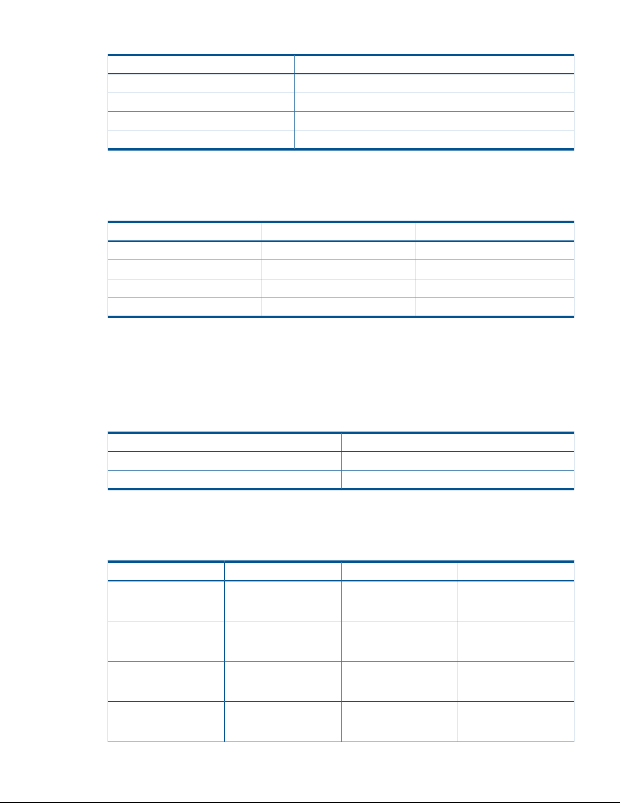
Table 3 Priority set for P-VOLs for which initial copy operation is performed
Value set for PriorityP-VOL
2LUN 00
3LUN 01
1LUN 02
4LUN 03
The order of starting initial copy and the Priority which is set for the P-VOLs are shown in the
following table.
Table 4 Correspondence relationship between order of starting initial copy and priority set for
P-VOLs
Value set for PriorityP-VOLOrder of starting initial copy
1LUN 021
2LUN 002
3LUN 013
4LUN 034
In this case, as the setting value of the Maximum Initial Copy Activities is 2, initial copy operations
for LUN 02 and LUN 00 are started. If either one of the initial copy operations for LUN 02 and
LUN 00 is completed, the initial copy for LUN 01 is started.
The next example explains the assignment of the scheduling order of initial copy operations in
cases where initial copy is already performed and two volume pairs are newly added. The P-VOLs
of the data volume pairs to be newly added and the Priority are shown in the following table.
Table 5 Priority set for P-VOLs of data volume pairs to be added
Value set for PriorityP-VOL
2LUN 10
1LUN 11
If initial copy is already started and if any initial copy is newly added, the additional initial copy
is started after the previously performed initial copy is completed. The Priority of all the initial copy
operations being performed is shown in the following table.
Table 6 Order of starting initial copy being performed
RemarkValue set for PriorityP-VOLOrder of starting initial copy
Data volume pair for which
initial copy is already
instructed to be performed
1LUN 021
Data volume pair for which
initial copy is already
instructed to be performed
2LUN 002
Data volume pair for which
initial copy is already
instructed to be performed
3LUN 013
Data volume pair for which
initial copy is already
instructed to be performed
4LUN 034
Planning pair volumes 27
Page 28

Table 6 Order of starting initial copy being performed (continued)
RemarkValue set for PriorityP-VOLOrder of starting initial copy
Data volume pair for which
initial copy is newly
instructed to be performed
1LUN 115
Data volume pair for which
initial copy is newly
instructed to be performed
2LUN 106
Priority is determined within the range of the number of initial copy operations performed at the
same time. Therefore, until the first initial copy operations complying with the order of the Priority
are completed, the additional initial copy operations are not started.
Disaster recovery considerations
You begin a disaster recovery solution when planning the Continuous Access Journal system. The
following are the main tasks for preparing for disaster recovery:
• Identify the data volumes that you wand to back up for disaster recovery.
• Pair the important volumes using Continuous Access Journal.
• Establish file and database recovery procedures.
• Install and configure host failover software error reporting communications (ERC) between the
primary and secondary sites.
For more information on host failover error reporting, see the following section. Also, review
“Disaster recovery operations ” (page 92) to become familiar with disaster recovery processes.
Host failover software
Host failover software is a critical component of any disaster recovery effort. When a primary
storage system fails to maintain synchronization of a Continuous Access Journal pair, the primary
storage system generates sense information. This information must be transferred to the remote site
using the host failover software for effective disaster recovery. RAID Manager provides failover
commands that interface with industry-standard failover products.
Sharing volumes with Continuous Access Synchronous, other program
products
Continuous Access Journal volumes can be shared with other program product volumes. Sharing
pair volumes results in enhanced replication solutions, for example when Continuous Access Journal
and Continuous Access Synchronous, Business Copy, or External Storage Access Manager volumes
are shared.
For planning information, see the following:
• “Continuous Access Journal configurations with Continuous Access Synchronous” (page 130)
• “Continuous Access Journal configurations with Business Copy” (page 143)
• “Continuous Access Journal configurations with External Storage Access Manager” (page 147)
• “Sharing Continuous Access Journal volumes ” (page 125) for the following program products:
LUN Expansion◦
◦ Virtual LUN
◦ Cache Residency
◦ LUN Manager
◦ Thin Provisioning
28 Planning volumes and systems
Page 29
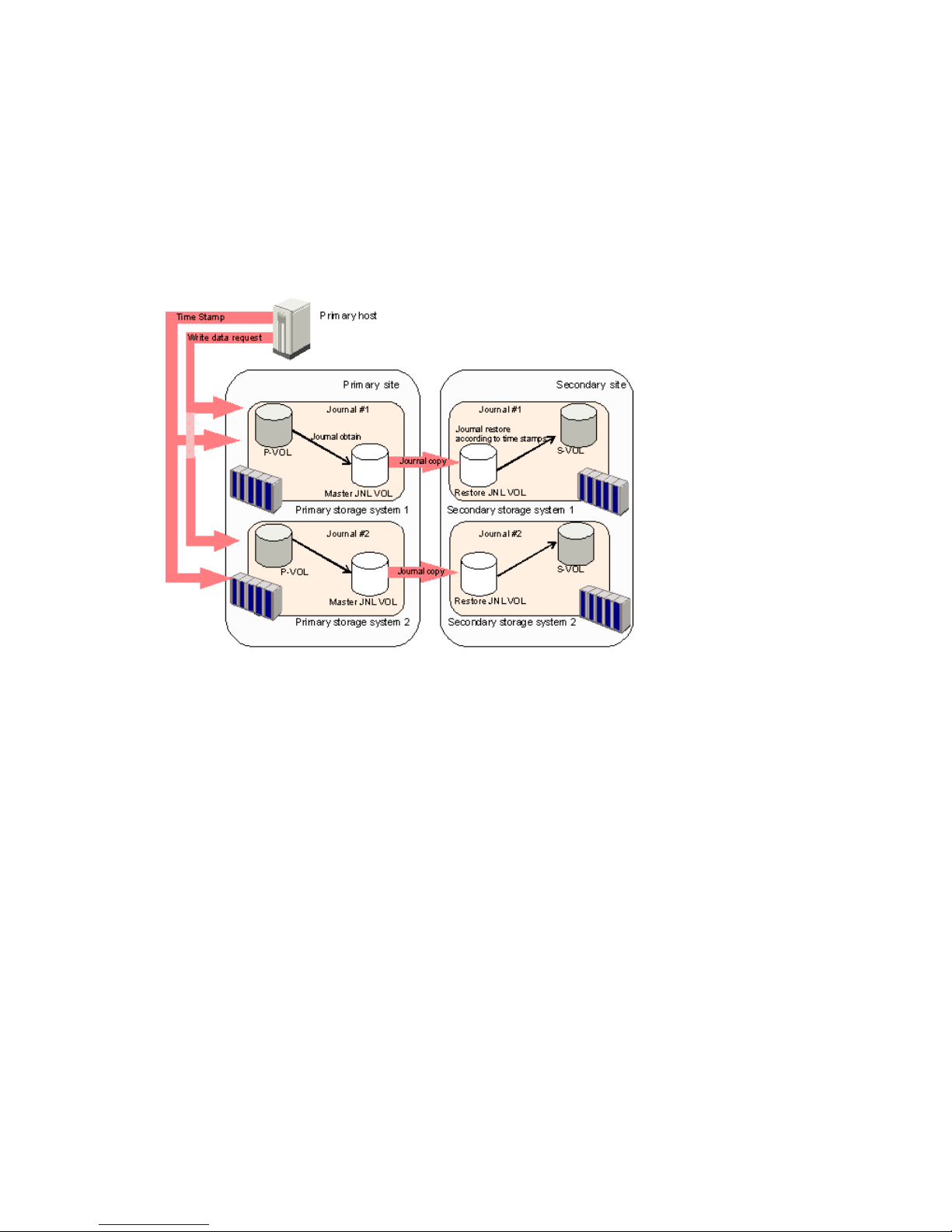
◦ Data Retention
◦ Performance Monitor
Planning for Continuous Access Journal with multiple P9500 systems
A Continuous Access Journal system can be configured with up to four primary P9500 systems
and four secondary P9500 system. Any combination of primary and secondary systems, from one
to four, may be used. Figure 4 (page 29) shows an example configuration with multiple primary
and secondary systems.
Figure 4 Using Continuous Access Journal with multiple storage systems
When primary hosts write data to P-VOLs, the hosts add a time stamp to the data. Secondary
systems check time stamps and then restore data to data volumes in chronological order (older
data are restored earlier), so that data update sequence is maintained.
Please note the following when working with multiple systems:
• Remote Web Console computers must be installed at primary and secondary sites.
• RAID Manager should be installed on the host in both the primary and secondary sites.
• Journal data is updated in the secondary systems based on the same time stamps and sequence
numbers issued by RAID Manager when the host issues the write requests to the primary
system(s). Time and sequence information remains with the data as it moves to the master and
restore journals and then to the secondary volume.
• Disaster recovery operations are possible. See “Disaster recovery when the system consists
of multiple primary and secondary storage systems” (page 94).
• If an error occurs in a journal, it is possible that all journals may become suspended by the
error. See “Suspension among journals ” (page 121) for more information.
Multiple journals per RAID Manager consistency group
Normally, only one journal can be registered in a RAID Manager consistency group. With multiple
P9500 systems, however, up to four journals may be registered in a RAID Manager consistency
group in the configuration of Figure 4 (page 29).
Planning for Continuous Access Journal with multiple P9500 systems 29
Page 30
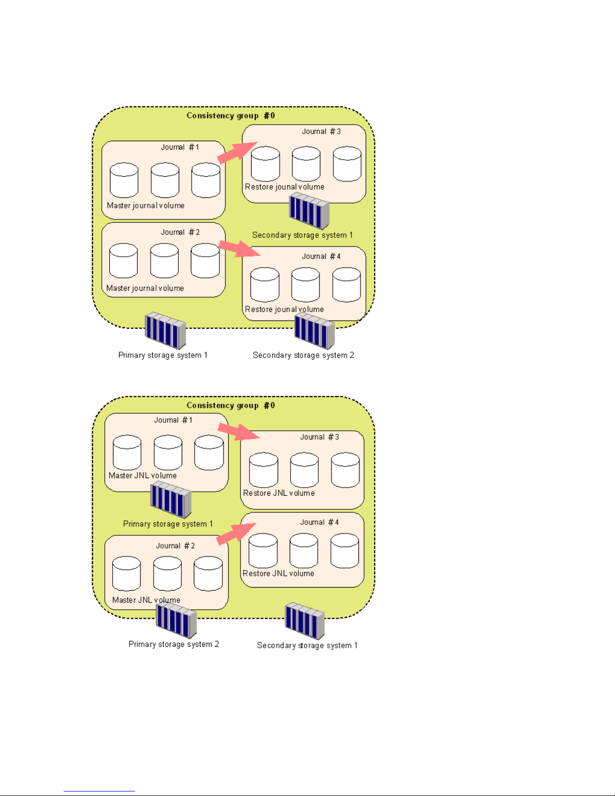
Figure 5 (page 30), Figure 6 (page 30), and Figure 7 (page 31) show varying configurations of
storage systems in which multiple journals are registered in a single RAID Manager consistency
group.
Figure 5 RAID Manager consistency group with multiple journals—1
Figure 6 RAID Manager consistency group with multiple journals—2
30 Planning volumes and systems
Page 31

Figure 7 RAID Manager consistency group with multiple journals—3
Planning for previous models
Continuous Access Journal can be used to perform remote copy operations between P9500 and
XP24000/XP20000 Disk Array. Data can be copied from P9500 to XP24000/XP20000 Disk
Array, or vice versa.
To execute remote copy from P9500 to XP24000/XP20000 Disk Array or vice versa, set up the
following:
• Configure a logical path between LDKC00 of the P9500 system and the XP24000/XP20000
Disk Array.
◦ More than one XP24000/XP20000 Disk Array can be connected to LDKC00 of P9500.
◦ LDKC01 cannot be used.
You can use the configuration instructions in this guide to set up the system. See “Configuration
operations” (page 43) for information.
Figure 8 Logical path between LDKC00 of P9500 and XP24000/XP20000 Disk Array
• P9500 corresponds to one system in the above-mentioned figure. XP24000/XP20000 Disk
Array corresponds to the other system in the above-mentioned figure.
• Set up the P9500 volume using a CU:LDEV number between 00:00 to EF:FF. As mentioned
above, the volume must be on LDKC00.
• Up to 32, 768 volumes can be used for volume pairs.
Planning for previous models 31
Page 32

• P9500 and XP24000/XP20000 Disk Array can be set up in 3-data center (3DC) cascading
or multitarget configurations. These configurations are used when combining Continuous
Access Synchronous and Continuous Access Journal systems. See “Continuous Access Journal
configurations with Continuous Access Synchronous” (page 130) to review these configurations.
There are no restrictions for the combining primary ad secondary sites between P9500 and
XP24000/XP20000 Disk Array .
• If you connect a P9500 with an XP12000 Disk Array, or a P9500 with an XP24000/XP20000
Disk Array, contact HP Technical Support for further information on the XP12000 Disk Array
and the XP24000/XP20000 Disk Array DKCMAIN program verison.
• If you connect P9500 with XP12000 Disk Array, CU:LDEV number from 00:00 to 3F:FF can
be used for P9500, but 40:00 or larger cannot be used.
Guidelines for preparing systems for Continuous Access Journal
Use the following guidelines to insure that your P9500 systems are ready for Continuous Access
Journal:
• Identify the locations where your Continuous Access Journal primary and secondary data
volumes will be located, then install and configure the P9500 systems.
• Make sure that primary and secondary systems are configured for P9500 Remote Web Console
operations. See HP P9000 Remote Web Console User Guide for information.
• Make sure that primary and secondary systems are properly configured for Continuous Access
Journal operations; for example, cache memory considerations. See the item for Cache and
Nonvolatile Storage in the requirements table, “System requirements” (page 17). Also consider
the amount of Cache Residency data to be stored in cache when determining the required
amount of cache.
• Make sure that primary and secondary systems have the system option modes specified that
may be required for your Continuous Access Journal configuration. See “System option modes
” (page 33), below for more information.
• Make sure that primary systems are configured to report sense information to the host.
Secondary systems should also be attached to a host server to enable reporting of sense
information in the event of a problem with a S-VOL or secondary system. If the remote system
is not attached to a host, it should be attached to a primary site host server so that monitoring
can be performed.
• If power sequence control cables are used, set the power select switch for the cluster to LOCAL
to prevent the primary system from being powered off by the host. Make sure the secondary
system is not powered off during Continuous Access Journal operations.
• Install the Continuous Access Journal remote copy connections (optical Fiber cables, switches,
etc.) between the primary and secondary systems.
• When setting up data paths, distribute them between different storage clusters and switches
to provide maximum flexibility and availability. The logical paths between the primary and
secondary systems must be separate from the logical paths between the host and secondary
system.
32 Planning volumes and systems
Page 33

System option modes
HP provides system option modes to tailor customer requirements on the P9500 system. System
option modes are used with Continuous Access Journal for the following:
• 2DC configuration using Continuous Access Journal and Continuous Access Synchronous
• Delta Resync configuration using Continuous Access Journal and Continuous Access
Synchronous
• Configuring split options for mirrors
Table 7 System option modes
DescriptionMode
Mode 448 ON: If the SVP detects a blocked path, the SVP assumes that an error
occurred, and then immediately splits (suspends) the mirror.
448
Mode 448 OFF: If the SVP detects a blocked path and the path does not recover within
the specified period of time, the SVP assumes that an error occurred, and then splits
(suspends) the mirror.
Note: The mode 448 setting is available only when mode 449 is set to OFF.
Mode 449 ON: The SVP does not detect blocked paths.449
Mode 449 OFF: The SVP detects blocked paths and monitors the time until the mirrors
get split (suspended).
Allows you to perform the initial copy operation of the Continuous Access Synchronous
pair for the suspended Continuous Access Journal pair.
474
Use the script file in which the following operations are described:
Initial copy operation of the Continuous Access Journal pair (None) -> Suspend the
Continuous Access Journal pair -> Initial copy operation of the Continuous Access
Synchronous pair -> Delete the Continuous Access Synchronous pair -> Resynchronize
the Continuous Access Journal pair. The performance of the initial copy processing of
the Continuous Access Journal pair can be improved by issuing the command from
RAID Manager.
Mode 474 ON: The performance of the initial copy processing of the Continuous Access
Journal pair can be improved by issuing the command from RAID Manager.
Mode 474 OFF: Normal operations are performed.
To create a Continuous Access Journal pair for delta resync operation in the 3DC
multitarget configuration, set this mode to ON.
506
Mode 506 ON: The delta resync operation is performed if there are no update I/Os.
Mode 506 OFF: The copy processing of all data is performed if there is no update
I/Os.
In the configuration where multiple MCUs share an RCU (Continuous Access Journal
Mx1 configuration), the mirror resynchronization or delta resync operation may fail
593
due to SSB=EB9D. SSB=EB9D is output as SSB log when the parameter of the
communication command is not saved in the shared memory. To reduce the number of
multiprocessing of the communication command issued from MCU to RCU for the status
transition of each pair, set this mode to ON. By setting this mode to ON, you can
prevent mirror resynchronization or delta resync operation from failing.
Mode 593 ON: The multiprocessing of the communication command issued from MCU
to RCU is up to 128 pairs per DKC.
Mode 593 OFF: The multiprocessing of the communication command issued from MCU
to RCU is up to 1024 pairs per DKC.
The host I/O response might decrease while the Continuous Access Journal pair is
resynchronized. To suppress increase in the MP utilization rate by the differential bitmap
retrieval processing when resynchronizing the pair, set this mode to ON.
760
Mode 760 ON: Decrease in host I/O response during the Continuous Access Journal
resync operation is reduced.
Guidelines for preparing systems for Continuous Access Journal 33
Page 34

Table 7 System option modes (continued)
DescriptionMode
Mode 760 OFF: Normal operations are performed.
System option modes can only be changed by an HP representative.
34 Planning volumes and systems
Page 35

4 Planning the data path
A data path must be designed to manage your organization’s throughput to the remote site.
Appropriate bandwidth, required number of ports, and the Fiber Channel data path configuration
you use help insure that your update data arrives at the remote site in a time consistent with your
organization’s RPO.
This chapter provides instructions for calculating bandwidth and designing the data path network.
Data path design workflow
To set up a data path, you need to establish the following:
• The amount of bandwidth necessary to move the data generated by your host application
under all I/O conditions
• Ports that can either send or receive data
• Understand Fibre Channel types and number of switches required
• A data path
This chapter discusses these topics in detail.
Sizing bandwidth
You purchase bandwidth according to the amount of data that will be transferred from the primary
to the secondary system within a certain amount of time.
If the data path network cannot keep pace with the flow of data, the data is saved in the journal
until additional bandwidth capacity becomes available. If the journal also cannot keep up, the
pair relationships will be lost and a resync or possibly a new initial copy must be performed.
In general, bandwidth is expensive. Adding capacity to a journal volume is relatively inexpensive.
But the more data that accumulates in the journal, the further the secondary image lags behind the
production volumes. Therefore, sizing bandwidth is a trade-off between expense and keeping your
secondary volumes as close in time as you require with the primary volumes.
Five sizing strategies
The following sizing strategies are provided to help you work out an approach to sizing bandwidth.
Be aware that these are not the only strategies you can use.
• Size bandwidth to peak workload. This results in the smallest time difference between data in
the P-VOL and S-VOL. Identify peak workload on the production disks, then add extra capacity
to accommodate packet loss and protocol overhead. RPO is as near zero as possible when
bandwidth is sized to peak workload.
• Size bandwidth to peak workload rolling average. The rolling average is less than peak but
more than average. This guarantees that at some point data will accumulate in the journal,
but most of the time it will not. The RPO in this case is based on the size of the journal when
the data path capacity is exceeded and the RPO will vary over time depending on the specific
workload being presented at any point in time. You must determine that the maximum RPO
provided is within the limit of your requirements.
• Size bandwidth to typical workload. When bandwidth is sized to typical write-workload, and
an extended peak workload is experienced, excess write-data (the data greater than the data
path capacity) is written to journal. This excess data is delayed for subsequent FIFO transmission
to the remote site when network capacity becomes available. The amount of data written to
the journal and accumulated there is proportional to the amplitude and duration of the workload
surge.
Data path design workflow 35
Page 36
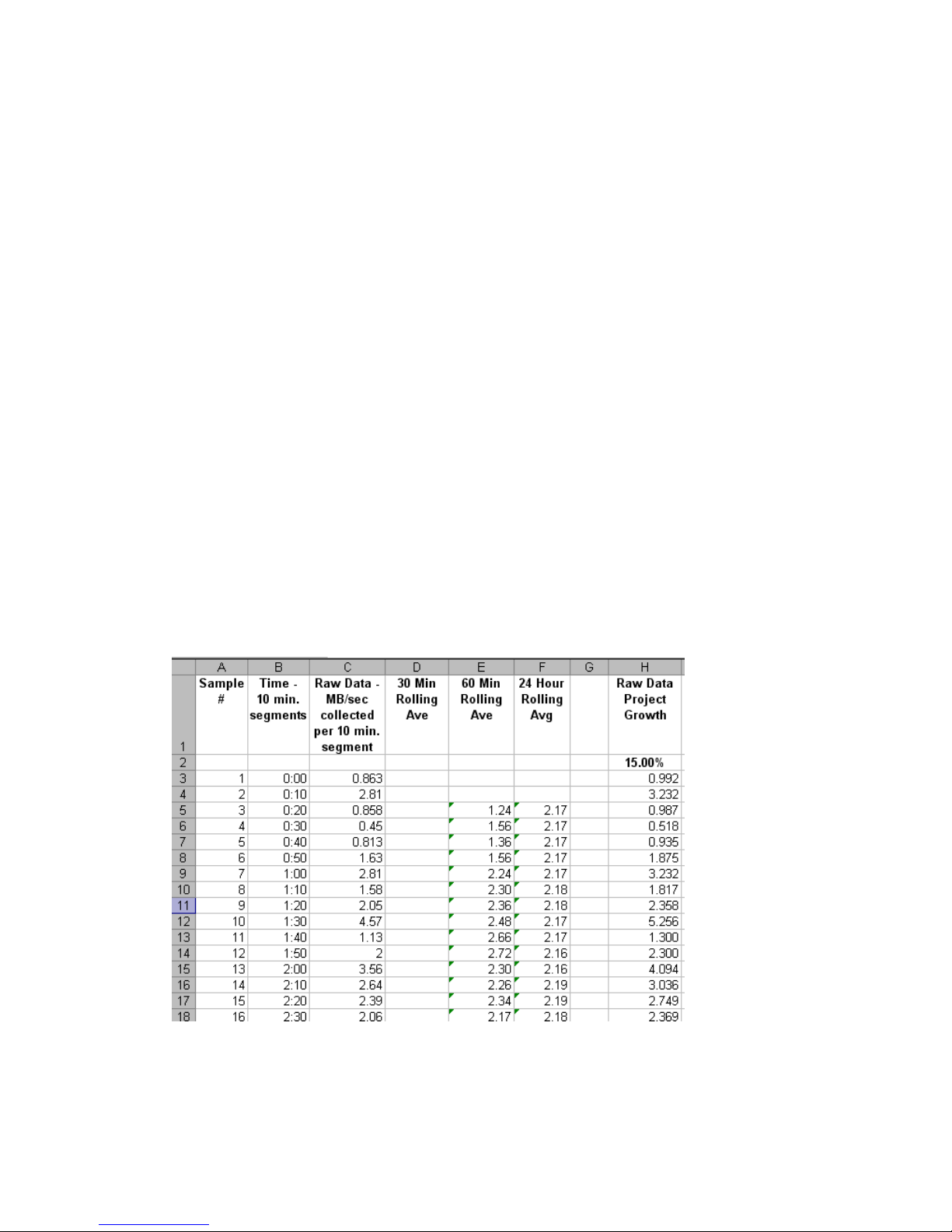
• If you cannot determine a “typical” workload, sizing should be to the average or mean
workload, plus a small compensation for network overhead. In this scenario, excess data in
the journals will be completely emptied to the S-VOL only occasionally. If bandwidth is sized
below average write-workload, the journals never fully drain and eventually overflow resulting
in the pairs suspending.
• You can size bandwidth and journal size for long-haul data migration, to be used where data
consistency is not required. In this strategy, you alternate pair status between resync and
suspend in order to “batch copy” point-in-time copies. When pairs are suspended, journals
are not used to queue write operations. Rather, a bitmap is used to track which cylinders have
changed on the physical disks. For access patterns that favor multiple writes to a relatively
small region of disk, this technique can provide especially efficient transfer of data, since
multiple writes to one region are not sent each and every time. Only the last update before
resync is sent. The disadvantage of this strategy is that it does not guarantee data consistency
on the secondary system until the resync completes.
Calculating bandwidth
To determine bandwidth for Continuous Access Journal, write-workload must be measured.
Production system workload data is collected using performance monitoring software. Please see
“Measuring write-workload” (page 21).
When you have collected write-workload data, size your bandwidth according to your sizing
strategy. In the following procedures, bandwidth is sized for peak and peak rolling average
write-workload.
Sizing bandwidth for peak write-workload
1. Make sure that write-workload data is imported into a spreadsheet tool. Column C in the figure
below shows an example of collected raw data over 10 minute segments.
Figure 9 Write-workload spreadsheet
2. Locate the highest peak. Based on your write-workload measurements, this is the greatest
amount of data transferred during the collection period. It indicates the base amount of data
that your bandwidth must be able to handle for near 0 RPO.
Though the highest peak is used for determining bandwidth, you should take notice of extremely
high peaks. In some cases a batch job, defragmentation, or other process could be driving
36 Planning the data path
Page 37
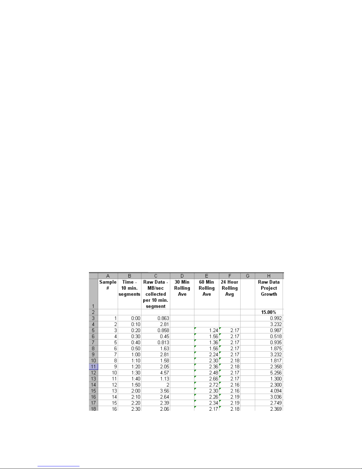
workload to abnormally high levels. It is sometimes worthwhile to review the processes that
are running. After careful analysis, it may be possible to lower or even eliminate some spikes
by optimizing or streamlining high-workload processes. Also, changing the timing of a process
may lower workload.
3. With a base bandwidth value established, make adjustments for growth and a safety factor.
• Projected growth rate accounts for the increase expected in write-workload over a 1, 2,
or 3 year period.
• A safety factor adds extra bandwidth for unusually high spikes that did not occur during
write-workload measurement but could.
Sizing bandwidth for peak rolling average write-workload
1. Using write-workload data imported into a spreadsheet and your RPO, calculate write
rolling-averages.
For example, if RPO time is 1 hour, then 60-minute rolling averages are calculated. Do this
by arranging the values in six 10-minute intervals, as follows:
a. In cell E5 type, =average(b2:b7), and press the Enter key. (Most spreadsheet tools
have an average function.)
This instructs the tool to calculate the average value in cells B3 through B8 (six 10-minute
intervals) and populate cell E5 with that data. (The calculations used here are for example
purposes only. Base your calculations on your RPO.)
b. Copy the value that displays in E5.
c. Highlight cells E6 to the last E cell of workload data in the spreadsheet.
d. Right-click the highlighted cells and select the Paste option.
Excel maintains the logic and increments the formula values initially entered in E5. It then
calculates all the 60-minute averages for every 10-minute increment, and populates the
E cells. This is shown in the following figure, which is an example using Microsoft Excel.
For comparison, 24-hour rolling averages are also shown.
Figure 10 Rolling averages calculated using 60 minute RPO
Sizing bandwidth 37
Page 38
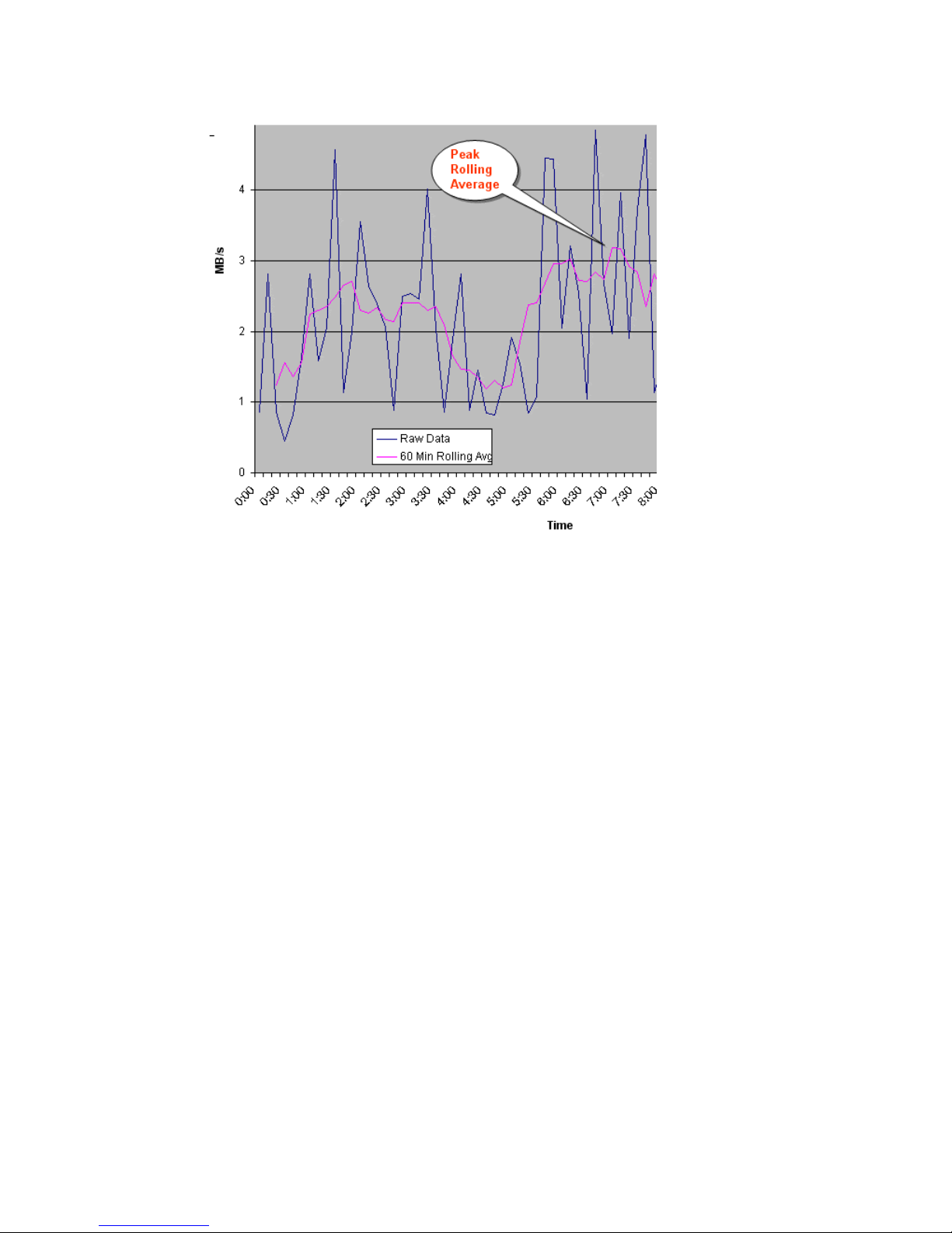
For another perspective, you can graph the data, as shown in Figure 11 (page 38).
Figure 11 60-minute rolling averages graphed over raw data
2. From the spreadsheet or graph, locate the largest or highest rolling average value. This is the
peak rolling average, which indicates the base amount of data that your bandwidth must be
able to handle.
3. With a base bandwidth value established, make adjustments for growth and a safety factor.
• Projected growth rate accounts for the increase expected in write-workload over a 1, 2,
or 3 year period.
• A safety factor adds extra bandwidth for unusually high spikes that did not occur during
write-workload measurement but could.
Latency
Network latency affects replication. It is the amount of data that can be present in the data path.
In the event of network failure, a certain number of transmitted records will not yet be resident in
the secondary system’s journal because they are still in-route within the data path. During periods
of low workload, there may be no records in the path, but during periods of heavy workload, the
network is fully used. This amount represents the minimum difference between data in the primary
and secondary systems.
Packet loss
Packet losses have the effect of reducing overall bandwidth because lost packets must be
retransmitted, which consumes network capacity that would otherwise be occupied by new data
traffic. Also, network quality can elongate the time of the data between the primary and secondary
sites since journals are not applied until a contiguous sequence of records has arrived at the
secondary site.
38 Planning the data path
Page 39

Planning ports for data transfer
Updated data is transferred along the data path from the initiator and RCU target ports on the
primary and secondary systems.
• Initiator ports control the specific data link they are part of.
• RCU target ports respond to commands from Initiator ports.
• The amount of data a port can transmit is limited.
Continuous Access Journal transfers data from the primary to the secondary storage system when
the secondary storage subsystem requests data. Hence, the data path to size for normal operations
is the path composed of links that have their Initiator ports in the secondary storage system and
their RCU target ports in the primary storage subsystem.
You must know the amount of data that will be transferred during peak periods. Then your need
to ensure that a sufficient number of your systems’ ports are specified as initiator and RCU target
ports to handle the potential amount of data.
The Fibre Channel ports on P9500 systems can have the following attributes:
• Target port: Connects the storage system and an open systems host. When the host issues a
write request, the request is sent to a volume on the P9500 system via a target port on the
storage system. Target ports are not used with mainframe volumes or Continuous Access
Journal operations. This port can be changed to an initiator, or RCU target port.
• Initiator port: Sends Continuous Access Journal commands to the paired storage system.
initiator ports must be configured on both primary and remote storage systems for Continuous
Access Journal operations.
• RCU Target port: Receives Continuous Access Journal commands and data. RCU target ports
must be configured on both primary and remote storage systems for Continuous Access Journal
operations.
• External port: Required for External Storage copy operations. This port is not used for
Continuous Access Journal copy operations. This port can be changed to a target, initiator,
or RCU target port.
NOTE: One or more initiator ports must be configured on both the primary and secondary storage
subsystems before you can add the secondary storage system and create Continuous Access Journal
volume pairs. A minimum of two initiator ports on both the primary and secondary storage
subsystems (configured on separate fibre channel CHAs) is highly recommended for redundancy.
Determining required number of ports
The primary and secondary systems require both initiator and RCU target ports. Both systems send
and receive traffic during active replication.
• The initiator port on the primary side is connected to the RCU target port on the secondary
side. These links carry status and command information during normal operation (e.g. copying
data from the primary to the secondary storage subsystem).
• The initiator port on the secondary side is connected to the RCU target port on the primary
side. These links carry the data traffic during normal operation and must be sized for the
required capacity.
Adding more ports increases the amount of data that can be transferred between systems.
To determine the required number of initiator and RCU target ports
The data transfer speed of your Continuous Access Journal Z ports must be greater than peak write
IOPS. This means that you must dedicate the number of ports to a Continuous Access Journal Z
pair that will be able to handle the peak IOPS generated by your production system. The minimum
Planning ports for data transfer 39
Page 40

number of ports for a Continuous Access Journal Z system is two. To determine the required number
of initiator and RCU target ports.
1. Measure IOPS for your production system. When you measure write-workload, IOPS is also
provided. (See “Measuring write-workload” (page 21)).
2. Using peak IOPS and the maximum IOPS for a VSP Fibre Channel port (70,000), calculate
the number of ports your Continuous Access Journal Z system requires. Peak IOPS / 70,000.
For example: if your performance monitoring software shows peak IOPS at 280,000, then the
calculation would be: 280,000 / 70,000 (max. IOPS per port) = 4. This example shows that four
ports are required for the measured peak IOPS.
On setting up ports
The following tips are provided to help you design your port configuration:
• When new data exists, the initiator port on the local system sends informational commands
to the secondary RCU target port.
• The remote system initiator port sends journal query commands to the local RCU target port.
When new data exists in the primary system, the data is sent through these ports — that is,
from primary side RCU target port(s) to secondary system initiator port(s).
An example configuration could consist of the following:
◦ Two initiator ports on the local side, with two matching RCU target ports on the remote
side
◦ Four initiator ports on the remote side, with four matching RCU target ports on the local
side.
◦ An initiator port on one side must have an RCU target port on the other side.
• If your system will support a disaster recovery failover/failback environment, initiator and
RCU target ports should be configured the same on the primary and secondary storage systems.
• Up to eight paths can be established in both directions. HP strongly recommends that you
establish at least two independent data paths to provide hardware redundancy.
• Host paths cannot be connected to an initiator port. However, they can be attached to RCU
target ports.
NOTE: One or more initiator ports must be configured on both the primary and secondary storage
subsystems before you can add the secondary storage system and create Continuous Access Journal
volume pairs. A minimum of two initiator ports on both the primary and secondary storage
subsystems (configured on separate fibre channel CHAs) is highly recommended for redundancy.
Distances supported for Fibre Channel type, number of switches
Fibre Channel multimode or single-mode optical fiber cables are required on primary and secondary
systems. The type of cable and number of switches depends on the distance between primary and
secondary sites.
• 0 to 0.5 km: multimode optical shortwave fiber cables are required.
• 0.5 km to 1.5 km (1,640 to 4,920 feet): multimode shortwave Fibre Channel interface cables
are required; one switch is required, two maximum.
• 1.5 km to 10 km: single optical long wave fiber cables are required.
• 10 km to 30 km (6.2 to 18.6 miles): single-mode long wave Fibre Channel interface cables
are required; one switch is required, two maximum.
• Greater than 30 km (18.6 miles): approved third-party channel extender products and
telecommunications lines are required.
40 Planning the data path
Page 41
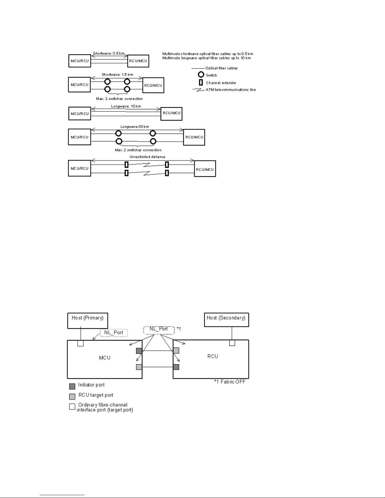
This information is illustrated in Figure 12 (page 41).
Figure 12 Data path types, switches, and distances
Supported data path configurations
The remote data path can be configured in one of the following connection types. But for switch
connection, the port should be set to Fabric on, Point-to-Point (F-port).
• Direct connection, as shown in Figure 13 (page 41). Direct connection (loop only) is a direct
link between the local and remote arrays. NL-port (Node Loop) are supported for the data
path and host-to-system path.
• Switch connection, as shown in Figure 14 (page 42). Switch connections push data from the
local switch through a Fibre Channel link across a WAN to the remote switch and Fibre
Channel to the remote system. F-port (Point-to-Point) and FL-port (Loop) switch connections are
supported.
• Extender connection, as shown in Figure 15 (page 42).
Figure 13 Direct connection configuration
Supported data path configurations 41
Page 42

Figure 14 Switch connection configuration
Figure 15 Extender connection configuration
NOTE:
• When an MCU and RCU are connected using switches with channel extenders, and multiple
data paths are assembled, the capacity of data to be transmitted may concentrate on particular
switches, depending on the configuration and the settings of switch routing.
• Make sure that your channel extenders are capable of supporting remote I/O. For further
details, contact your HP account team.
42 Planning the data path
Page 43

5 Configuration operations
This chapter provides the configuration tasks that will make your primary and secondary systems
ready for Continuous Access Journal pair operations.
Configuration workflow
You will set up primary and secondary systems for Continuous Access Journal operations as follows.
Check the prerequisites for each procedure. Some tasks need to be performed from both local and
remote storage systems and other tasks need to be performed from the local or remote storage
system.
1. Log in to Remote Web Console.
2. Define the Fibre Channel port attributes that will be used for Continuous Access Journal. See
“Define Fibre Channel port attributes ” (page 43), below.
3. Set up logical paths between the primary and secondary systems. See “Configure storage
systems for Continuous Access Journal, define logical paths ” (page 45).
4. Register journal volumes in a journal. See “Register journal volumes in a journal ” (page 50).
You may also perform these additional procedures prior to the initial copy:
• Add additional logical paths. See “Configure additional logical paths ” (page 47).
• Specify the number of volumes to copy. See “Specify number of volumes for initial copy, resync
” (page 48).
Define Fibre Channel port attributes
Initiator, and RCU target ports must be set up on the primary and secondary systems for Continuous
Access Journal command and data transfer.
Prerequisite information
• If initiator ports and RCU target ports are not configured on both primary and remote storage
systems, the following problems occurs and remote copy operations are not performed:
◦ The administrator at the primary site will be unable to create any pair of a primary data
volume and a secondary data volume.
◦ The secondary storage system will be unable to read data from journal volumes in the
primary storage system.
• Before a fiber channel target port can be changed to an initiator port, the following must be
performed:
◦ Disconnected from the host.
◦ All affected pairs must be released.
◦ All logical paths from the initiator port to remote storage system must be deleted
◦ After deleted logical paths, all cables to the port must be removed.
Configuration workflow 43
Page 44

• Before a fiber channel initiator port can be changed to target or RCU target, the following
must be performed:
◦ All affected data volume pairs must be released.
◦ All logical paths must be deleted from the initiator port to the remote storage system.
◦ After logical paths are deleted, cables connecting the local system to the remote system
must be removed.
• The number of hosts connected to a target port must be limited to 128 or fewer to avoid illegal
disconnection.
See the section on planning ports in the“Planning ports for data transfer ” (page 39) for information
on target, initiator, and RCU target ports and to determine the number of initiator and RCU target
ports required by your system.
To define port attributes
1. In Remote Web Console, select Actions > Remote Copy > Continuous Access Journal > DKC
Operation.
2. Click to change the mode from View to Modify.
3. In the Display box, select Port. The ports associated with the local storage system are listed.
4. Right-click the port that you want to change and select the desired port type, Initiator, RCU
Target, or Target).
5. Select all the port attributes that you want to change, review the Preview list.
CAUTION: Read and follow the important caution before applying the port attribute changes.
• To change the setting, right-click the port in the upper right list and select the attribute.
• To release the setting, right-click the item in the Preview list and select Delete.
6. Click Apply to apply the settings. If an error occurs, the error code appears in the rightmost
column of the Preview list. To view detailed information about the error, right click the error
code and select Error Detail.
44 Configuration operations
Page 45

Configure storage systems for Continuous Access Journal, define logical
paths
Prerequisite Information
• This procedure must be performed on both primary and secondary systems.
• The primary and secondary systems must already be configured for Continuous Access Journal
operations. See “System requirements” (page 17) for more information.
• The data path must be set up. See “Planning the data path” (page 35) for more information.
• The port attributes on the primary and secondary systems must be configured for Continuous
Access Journal. See “Define Fibre Channel port attributes ” (page 43).
• The system’s serial number, SSID, and the CU will be required during this procedure.
To set up the Continuous Access Journal logical path(s)
1. In Remote Web Console, select Actions > Remote Copy > Continuous Access Journal > DKC
Operation. The DKC Operation window displays.
2. Click to change the mode from View to Modify.
3. In the Display box, select DKC. The tree and full list on the right-side display information about
all remote storage systems.
4. Locate the list on the right-side, right-click, and select DKC Operation > Add DKC. The Add
DKC dialog box is displayed.
Configure storage systems for Continuous Access Journal, define logical paths 45
Page 46

5. In the S/N box, enter the remote system’s 5-digit serial number.
6. In the LDKC box, select the remote system’s LDKC number.
Enter 00 when the remote system is P9500, XP24000/XP20000 Disk Array, or XP12000
Disk Array/XP10000 Disk Array.
7. In the Controller ID box, select the remote system’s controller ID. The controller ID for a P9500
storage system is 6. The controller ID for a XP24000/XP20000 Disk Array storage system is
5. The controller ID for a XP12000 Disk Array/XP10000 Disk Array storage system is 4.
8. The Path Gr. ID check box is intended for a future release. Continue to the next step.
9. In the M-R Path box, define the Fibre Channel port of the logical paths between the local
storage system and the remote storage system:
1. In the Port, select a local system initiator port.
2. In the Pair-Port, select the remote system RCU target port. This establishes a logical path
with the selected initiator port.
You may enter port numbers using the keyboard. You may abbreviate the number into
two characters. For example, “1A” may be entered instead of “CL1-A”. Letters may be
uppercase or lowercase.
10. Click the Option . The DKC Option dialog box displays, as shown below.
46 Configuration operations
Page 47

11. The Minimum Paths box is intended for a future release. Continue to the next step.
12. RIO MIH means “Remote I/O Missing Interrupt Handler”.
In the RIO MIH Time box, enter the amount of time from 10 seconds to 100 seconds (15
seconds is the default).
13. Click Set.
14. See the Preview list to check the settings that you have made.
• If you want to modify a setting, select and right click the item in the Preview list and then
select Modify.
• If you want to cancel a setting, select and right click the item and then select Cancel.
15. Click Apply to apply the settings. If an error occurs, the error code appears in the rightmost
column of the Preview list. To view detailed information about the error, right click the error
code and select Error Detail.
Configure additional logical paths
You can configure additional logical paths as needed. A maximum of eight logical paths are
supported.
Prerequisite information
Please review the prerequisites for configuring logical paths in “Configure storage systems for
Continuous Access Journal, define logical paths ” (page 45).
To configure additional logical paths
1. In Remote Web Console, select Actions > Remote Copy > Continuous Access Journal > DKC
Operation.
2. Click to change the mode from View to Modify.
3. In the Display box, select DKC. The tree and full list on the right-side display information about
remote storage systems.
4. In the tree, select the remote system. The logical paths display in the full right-side list.
5. Right-click a logical path and select Add Path from the menu.
Configure additional logical paths 47
Page 48
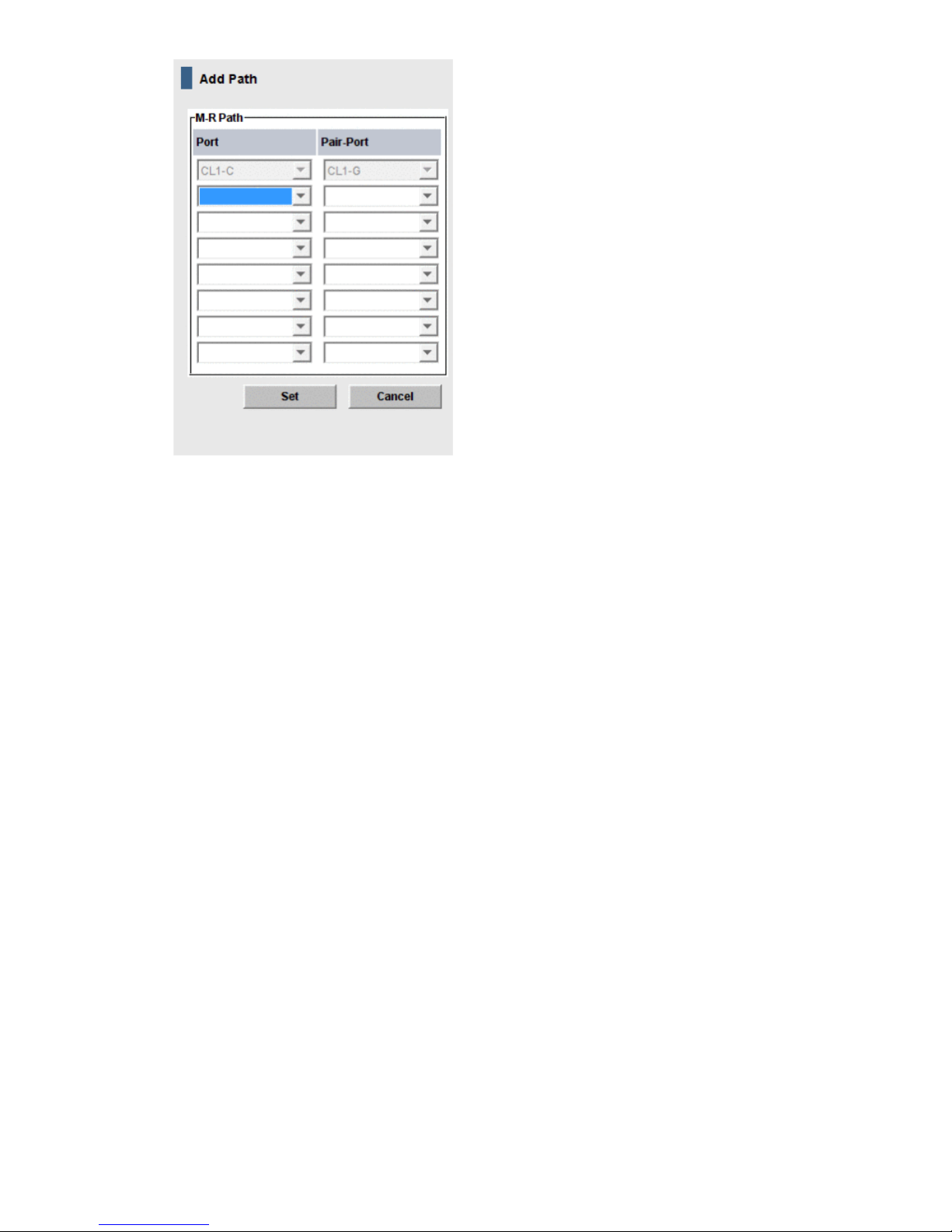
6. In the M-R Path box, define the Fibre Channel port used by logical path between local and
remote systems:
1. In the Port, select a local system initiator port.
2. In the Pair-Port, select the remote system RCU target port.
You may enter port numbers using the keyboard. You may abbreviate the number into
two characters. For example, “1A” may be entered instead of “CL1-A”. Letters may be
uppercase or lowercase.
7. Click Set and close the Add Path dialog box.
8. See the Preview list to check the settings that you have made.
• If you want to modify a setting, select and right click the item in the Preview list and then
select Modify.
• If you want to cancel a setting, select and right click the item and then select Cancel.
9. Click Apply to apply the settings. If an error occurs, the error code appears in the rightmost
column of the Preview list. To view detailed information about the error, right click the error
code and select Error Detail.
Specify number of volumes for initial copy, resync
You can specify the number of volumes to be copied concurrently during an initial copy and
resynchronization operations.
48 Configuration operations
Page 49
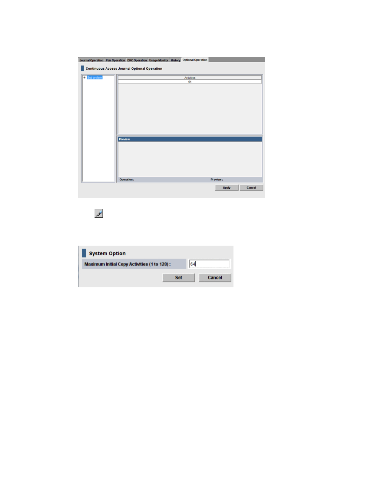
To specify number of volumes to copy concurrently
1. In Remote Web Console, select Actions > Remote Copy > Continuous Access Journal > Optional
Operation.
2. Click to change the mode from View to Modify.
3. Right-click the value that displays under Activities in the right-side pane, then select Change
System Option from the menu. The System Option dialog box displays.
4. In the Maximum Initial Copy Activities box, enter the number of volumes that you want to be
copied concurrently during initial copy and resynchronization operations, then click Set. The
number can range from 1 to 128 volumes. The default is 64 volumes.
• This setting may impact the performance of the primary storage system. This depends on
the number and the amount of I/O activity. By using the default, 64 volumes, you limit
the impact of initial copy operations on storage system performance.
• When you specify more than 64, the system starts the first 64 pairs but does not start the
65th pair until one of the pairs is synchronized.
5. Click Set when finished.
6. See the Preview list in the Journal Operation window to check the settings that you have made.
• If you want to modify a item, select and right click the setting in the Preview list and then
select Modify.
• If you want to cancel a item, select and right click the setting and then select Cancel.
7. Click Apply to apply the settings. If an error occurs, the error code appears in the rightmost
column of the Preview list. To view detailed information about the error, right click the error
code and select Error Detail.
Specify number of volumes for initial copy, resync 49
Page 50
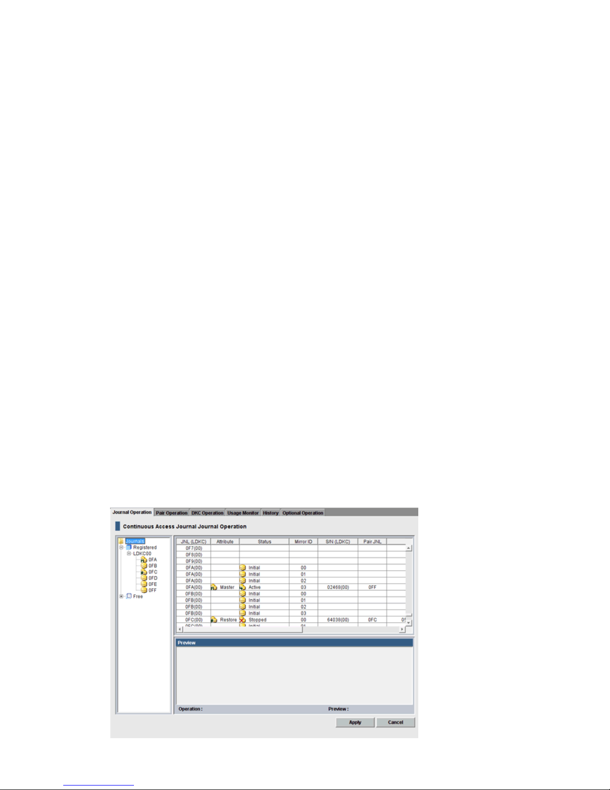
Register journal volumes in a journal
You set up journal volumes by registering them in a journal. The procedure is provided below.
Prerequisite information
• The emulation type of the volume that can be registered in the journal is only OPEN-V. For
details, see (page 17).
• Journal volumes must be registered in a journal before the initial pair-copy operation is
performed.
• Journal volumes must be registered on both local and remote systems.
• A journal can contain up to 64 journal volumes.
• Journal volumes must be set up and sized according to your Continuous Access Journal system’s
requirements. For more information, see “Sizing journal volumes ” (page 22).
• Journal volumes can be added to a journal under the following conditions:
The journal is not used.◦
◦ When pair operations are not in progress and the status of the journal of the mirror is
Active, Stopped, Hold, Holding, or Hold(Failure).
• Journal volumes cannot be added to a journal under the following conditions:
When pair operations are in progress and the status of the journal of the mirror is Active,
Stopped, Hold, Holding, or Hold(Failure).
◦
◦ When Cache Residency settings are defined for the volumes.
• If a path (LU path) is defined from a host to a volume, you cannot register the volume to a
journal. Also, a journal volume cannot have a LU path defined to it from a host. Hosts cannot
read from and write to journal volumes.
• Do not register a volume to a journal during quick formatting. Doing so stalls quick formatting
operation.
To register journal volumes
1. In Remote Web Console, select Actions > Remote Copy > Continuous Access Journal > Journal
Operation. The Journal Operation window is displayed.
50 Configuration operations
Page 51
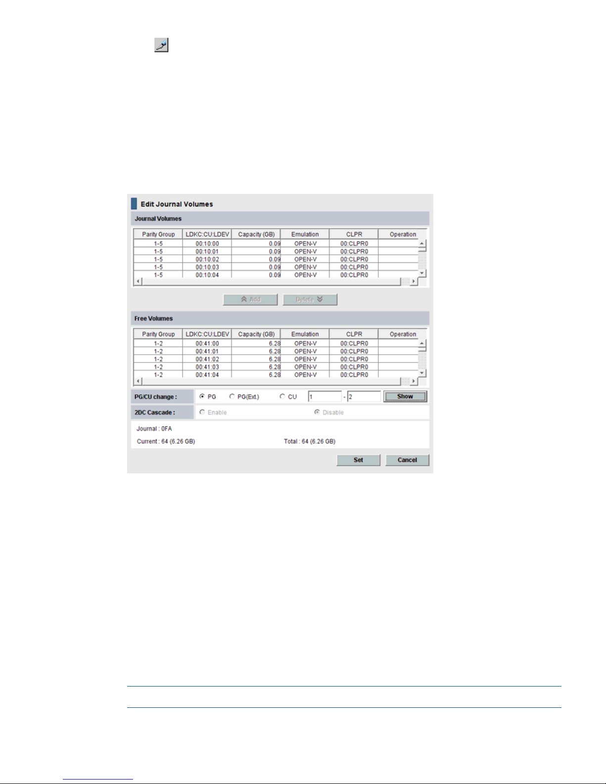
2. Click to change the mode from View to Modify.
3. To register journal volumes in an existing journal, select the journal from the Registered tree.
To register journal volumes in a new journal, select the journal from the Free tree.
The selected journal displays in the upper-right list of the window.
The journal volume cannot be registered when there are mirrors other than the following
statuses in the journal of the Registered:
Status: Initial, Active, Stopped, Hold, Holding, or Hold(Failure).
4. Right-click the selected journal then select Edit Journal Volumes from the menu. The Edit Journal
Volumes dialog box displays.
5. In the Free Volumes list, select the volumes that you want to register. Each row represents a
volume in the list.
If you cannot find the volumes, select one of the following in the PG/CU change area:
• PG, then enter a parity group number in the box, and click Show. A list of volumes in the
specified parity group displays. Select the volumes that you want to register.
• PG(Ext.), then enter the external parity group number in the box, and click Show. A list
of volumes in the specified external parity group displays. Select the volumes that you
want to register.
Though parity group numbers for external volumes start with the letter "E", you do not
need to enter "E" in the text boxes. For example, to specify the parity group number
"E1-2", you would enter 1 and 2 into the text boxes.
• CU, then select a CU number from the list. A list of volumes in the specified CU displays.
Select the volumes that you want to register.
NOTE: In the current version, the Free Volume list shows only OPEN-V volumes.
6. Click Add. The added display in the Journal Volumes list, and the Operation column of the
list displays Add.
Register journal volumes in a journal 51
Page 52

7. Click Set to close the Edit Journal Volumes dialog box.
8. See the Preview list in the Journal Operation window to check the journal volumes that you
have added.
• If you want to add a another volume, select the journal to add a volume in the Preview
list and right click and then select Modify. If the window opens, add a volume.
• If you want to cancel a setting, select the volume in the Preview list and right click and
then select Cancel.
9. Click Apply to register journal volumes.
After journal volumes are registered in the unused journal, the journal groups are shown below
Registered in the tree. If an error occurs, right click the item in the Preview list and select Error
Detail.
52 Configuration operations
Page 53

6 Pair operations
This chapter provides procedures and prerequisite information for performing Continuous Access
Journal copy operations.
Pair operations workflow
Basic Continuous Access Journal operations consists of the following.
• Always check pair status. Each Continuous Access Journal operation requires the pair to be
in a specific status.
• Create the pair, in which the S-VOL becomes a duplicate of the P-VOL.
• Split the pair, which separates the P-VOL and S-VOL and allows read/write access to the
S-VOL if desired.
• Restore the pair, in which the S-VOL again mirrors the ongoing, current data in the P-VOL.
• Delete a pair, which removes the pair relationship from the volumes.
For disaster recovery procedures, see “Disaster recovery operations ” (page 92).
Check pair status
Every Continuous Access Journal operation requires that the pairs have a specific status. Before
performing any operation, check pair status.
• Find status requirements under the Prerequisites sections for each operation.
• To view a pair’s current status in the GUI, or review status definitions, see “Monitor pair activity
and status” (page 67).
Create the initial copy
When you create the initial copy, all data in the P-VOL on the primary storage system is copied
to the S-VOL on the secondary storage system. The P-VOL remains available to the host for I/O
operations.
Prerequisite information
• The initial copy is performed from the primary storage system.
• The initial copy can be performed when the volumes are in the status of SMPL.
• S-VOLs must be offline to all hosts.
• You will be required to select the volumes you will assign to a pair or pairs by the individual
volume’s port, GID, and LUN.
• Connect the primary and secondary systems, and all logical paths must be defined. See
“Configure storage systems for Continuous Access Journal, define logical paths ” (page 45)
for more information.
• Journal volumes must be registered to the journals that are associated with pairs. See “Register
journal volumes in a journal ” (page 50) for more information.
• You will assign master and restore journals to the P-VOL and S-VOL during the operation.
• If you are creating more than one pair at one time, you must specify the number of volumes
that initial copy operations can be performed concurrently on. See “Specify number of volumes
for initial copy, resync ” (page 48) for more information.
Pair operations workflow 53
Page 54
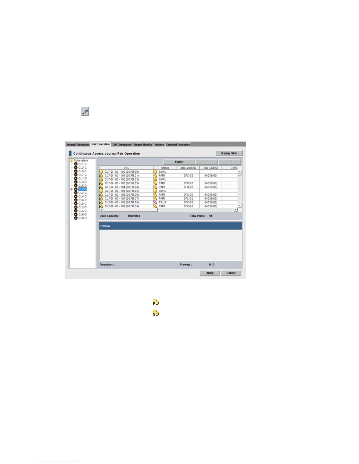
• If you are creating a Continuous Access Journal pair for delta resync, make sure all requirements
are met. See “Creating a delta resync pair ” (page 137).
• If this program product is running on a primary storage system or secondary storage system,
stop Performance Monitor before performing the initial copy to avoid overloading with TCP/IP
traffic. For details about Performance Monitor, see HP P9000 Performance for Open and
Mainframe Systems User Guide.
To create an initial copy or copies
1. In Remote Web Console, select Actions > Remote Copy > Continuous Access Journal> Pair
Operation.
2. Click to change the mode from View to Modify.
3. In the tree, select the port of the P-VOL or host group (displayed below the ports). The volumes
available for pairing display in the right-side list area.
4. Right-click a volume that you want as a P-VOL and select Paircreate from the menu.
• Volumes with the pair icon are already used as P-VOLs.
• Volumes with the pair icon are already used as S-VOLs.
• You can create more than one pair at one time. In this case, all the S-VOLs must be in
the same secondary system.
54 Pair operations
Page 55
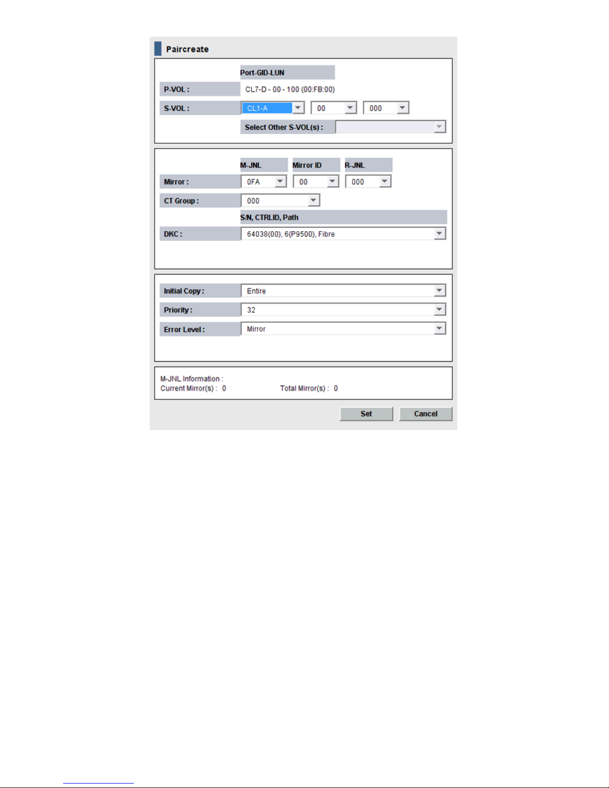
• Data for the selected volume displays in the P-VOL box. The numbers indicate the port,
GID, LUN, and volume.
• One P-VOL displays at a time, even if you selected multiple volumes for pairing. The
volume with the lowest number displays first.
5. Specify an S-VOL as follows:
1. Select the port, GID, and LUN from the three S-VOL , left to right. If you selected multiple
volumes as P-VOLs, the S-VOL you specify by the list is paired with the P-VOL displayed
in P-VOL.
Create the initial copy 55
Page 56

2. If multiple pairs are created at one time, use the Select Other S-VOL(s) list to specify
S-VOLs.
If you selected multiple volumes as P-VOLs, you can instruct the system to automatically
assign S-VOLs for the remainder of P-VOLs. Do this from the Select Other S-VOL(s) list, as
follows:
- Select Increment to cause Continuous Access Journal to add the secondary system LUN
incrementally. Your S-VOL LUN numbers must be numbered incrementally. For example,
if you create 3 pairs and specify 011 on the LUN of P-VOL, the LUNs on the secondary
system are incremented at 011, 012, and 013.
- Select Input Next to specify S-VOL LUN one at a time for each P-VOL. For example, if
after setting the S-VOL LUN for the current P-VOL you click the Set, then you would reopen
the dialog box to set the next S-VOL, and so on.
- Select Relative to P-VOL to cause Continuous Access Journal to add S-VOL LUN closest
in number to the P-VOL’s LUN. For example, if the LUN numbers of the three P-VOLs are
001, 005, and 006; and you select LUN 002 for the first S-VOL, LUN numbers 006 and
007 will be assigned by the system as the next two S-VOLs.
If you select and right click more than one volume in the Preview list and then select
Modify, the Paircreate dialog box opens and the Select Other S-VOL(s) list indicates No
Change. If you want to change the setting with this list, select another option from the list.
6. In the Mirror box, proceed as follows.
1. Select the master journal from the M-JNL list. In the M-JNL list, the number of existed
journal other than restore journal is displayed.
2. Select a mirror ID (0 to 3) from the Mirror ID list.
3. Select a restore journal from the R-JNL list. In the R-JNL list, the all number of journal
between 000 and 0FF are displayed.
NOTE: The M-JNL drop-down dialog box does not display journal numbers used by
Continuous Access Journal Z.
7. From the CT Group list, specify the consistency group number. If possible, assign the consistency
group number matching the Continuous Access Journal journal number (best practice).
8. In the Initial Copy list, select one of the following:
• Entire, to create the Continuous Access Journal pair relationship and copy the data from
primary to secondary volumes immediately.
• None, to create the Continuous Access Journal pair relationship but copy no data from
primary to secondary volumes. You must be insure that data in the P-VOL and S-VOL are
identical when selecting None.
• Delta, to create the Continuous Access Journal pair for a delta resync. No initial copy
operation starts after the volume pair is created. The status of the volume pair changes
to HOLD or HOLDING.
9. In the Priority list, specify the scheduling order for the initial copy operation. The default value
is 32, and 1 to 256 can be specified.
For performing more initial copy operations than the setting value of the Maximum Initial Copy
Activities set on the System Option dialog box, the scheduling order (Priority) can be set for
the initial copy operations to be performed.
The Priority is determined within the range of the number of initial copy operations performed
at the same time. Therefore, until the first initial copy operations complying with the order of
the Priority are completed, the additionally specified initial copy operations are not started.
If a time-out error occurs during the Add Pair operation, the copy operation may not be
executed correctly in the order specified in the Priority field. A time-out error may be caused
56 Pair operations
Page 57

by the CU configuration or a remote copy path error. Review the error, release the pair with
the error, and then retry the Paircreate operation.
10. In the Error Level list, select one of the following options to take place in the event a failure
occurs during this operation:
• Mirror, to cause all pairs in the failed pair’s mirror to be split. Mirror is the default.
• LU, to cause only the pair that failed to be split.
11. Click Set to close the Paircreate dialog box.
12. See the Preview list to check the settings that you have made.
• If you want to modify a setting, select and right-click the item in the Preview list and then
select Modify.
• If you want to delete a item, select and right-click the item in the Preview list and then
select Delete.
13. Click Apply to apply the settings and create pairs. If an error occurs during creating pairs,
right click the item in the Preview list and select Error Detail.
14. In the Pair Operation window, verify that pair status is correct based on the initial copy option
you selected in Step 8.
Current Pair Status Should BeInitial Copy Option
COPY or PAIREntire or None
HOLD, HoldingDelta
15. You can monitor the progress of the paircreate operation by clicking File > Refresh in the
menu bar. This updates the information in the list.
You can also review current pair activity and pair status on the Detailed Information dialog
box. See “Monitor pair activity and status” (page 67) for more information.
Split a pair
When you split a pair, write-data is no longer sent to S-VOL and the pair is no longer synchronized.
Splitting a pair or mirror gives you a point-in-time copy. For details about a point-in-time copy, see
“Create a point-in-time copy ” (page 59).
Prerequisite information
• A pair can be split from the primary or secondary system.
• Pair status must be COPY or PAIR to perform the split operation.
• If you want to split multiple pairs at the same time, the pairs must belong to the same mirror.
Doing this insures sequence consistency among S-VOLs in the mirror.
• Best practice is to perform pair split when I/O load is low. This reduces impact on performance.
Operations on multiple pairs in the same consistency group with different statuses may result
in suspension during high periods of write I/O.
• Journal data may not be copied to the S-VOL depending on the option you select.
• During normal Continuous Access Journal operations, the secondary system rejects write
operations to an S-VOL. However, you can enable write operations to the S-VOL during the
pair split operation. When you do this, then resync the pair, the secondary system sends the
S-VOL track bitmap to the primary system to insure proper resynchronization of the pair. This
S-VOL Write option is described in the pair-split procedure.
Split a pair 57
Page 58

To split one or more pairs
1. In Remote Web Console, select Actions > Remote Copy > Continuous Access Journal > Pair
Operation.
2. Click to change the mode from View to Modify.
3. In the tree, select the port or host group. Paired volumes are displayed in the upper-right-side
list area.
4. Select the pair that you want to split, right-click, and select Pairsplit-r from the menu. The dialog
box displays.
5. From the S-VOL Write list, select one of the following:
• Enable to permit hosts to write data to the S-VOL.
• Disable (the default) to prevent hosts from writing to the S-VOL
6. From the Range list, select one of the following:
• LU to split only the selected pair or pairs.
• Mirror to split all pairs in the same mirror(s) as the selected pairs
If the following two conditions are satisfied and you select Apply, a warning message
appears and processing cannot continue.
- The Preview list contains two or more pairs belonging to the same mirror.
- The Range column shows Mirror for at least one of the above pairs.
To be able to continue processing, do either of the following:
- Ensure that the Range column shows LU for all pairs in the same mirror.
- In the Preview list, select one pair in one mirror, and then other pairs in the mirror is
excluded.
7. From the Suspend Mode list, select one of the following:
• Flush :
When you split the pair, update data is copied to the secondary data volume. When the
secondary storage system receives a request for splitting a pair, all the journal data (that
is, update data) that the pair retains is written to the secondary data volume. After that,
the status of the pair changes from Suspending to PSUS if the pair does not retain any
journal data for a certain period of time.
• Purge :
When you split the pair, update data is not copied to the secondary data volume. If you
restore the pair later, the update data is copied to the secondary data volume.
8. Click Set when finished.
58 Pair operations
Page 59

9. See the Preview list to check the settings that you have made.
• If you want to modify a setting, select and right click the item in the Preview list and then
select Modify.
• If you want to delete a item, select and right click the item in the Preview list and then
select Delete.
10. Click Apply to apply the settings. If an error occurs during creating pairs, right click the item
in the Preview list and select Error Detail.
You can verify the PSUS status when the operation is completed.
Split a mirror
If a mirror is split, all the pairs in the mirror are split, and the data copy from the primary journals
to the secondary journals is suspended.
Prerequisite information
• A mirror can be split from the primary or secondary system.
• Mirrors must be in Active status.
To split a mirror
1. In Remote Web Console, select Actions > Remote Copy > Continuous Access Journal > Journal
Operation.
2. Click to change the mode from View to Modify.
3. In the tree, expand Registered then select the desired LDKC. Journals display in the tree and
mirrors display in the right-side pane.
As another way, select Journal in the tree. Mirrors display in the right-side pane.
4. Select one or more mirror with the desired mirror ID(s). The status of the mirror must be Active.
5. Right-click and select Mirror >Pairsplit-r from the menu. The Pairsplit-r dialog box displays.
6. Complete the procedure (see Step 4 to Step 9 on (page 57). However, you cannot change
Mirror of the Range list in step 5.
7. Click Apply to split the mirror. If an error occurs during creating pairs, right-click the item in
the Preview list and select Error Detail.
You can verify the Stopped status of the mirror when the mirror split operation is completed.
Create a point-in-time copy
Continuous Access Journal allows you to make Point-in-Time (PiT) duplicates of groups of volumes.
The term "Point-in-Time (PiT)" refers to an act of obtaining a copy of data immediately when you
want to obtain it. Continuous Access Journal can be used to create a PiT copy of data volumes
belonging to a journal.
To produce a PiT duplicate of the volumes in a journal
1. Stop all write I/Os from hosts to P-VOLs in the journal.
2. After all write I/Os to P-VOLs have stopped, split the mirror. Use the Suspend Pair dialog box
and then specify Mirror for Range and specify Flush for Suspend Mode.
3. When the status of all pairs in the journal has changed to Suspend, the duplicate set of volumes
is complete. If desired, you can restart your business application at the primary storage system
to resume business activities.
Split a mirror 59
Page 60

Restore a pair
If the pair is restored, the suspended data copy from the primary data volumes to the secondary
data volumes is resumed. If the delta resync pair is restored, the delta resync processing is
performed.
This section describes the pair resync operation. Also, the instructions are used when performing
the delta resync operation.
Prerequisite information
• The pair resynchronizing operation is performed from the primary storage system only.
• Pairs in PSUS or PSUE status is resynchronized.
• Best practice is to resynchronize when I/O load is low. This reduces impact on performance.
Operations on multiple pairs in the same consistency mirror with different statuses may result
in suspension during high periods of write I/O.
Prerequisites for delta resync operation
The delta resync operation is executed by selecting delta-resync only options during the resync
operation. If executing delta resync, please observe the following.
• Status of the delta resync pair must be HOLD or HOLDING. If the pair status is in HLDE status,
you can change the status to HOLD by performing the pairresync operation.
• Status of the Continuous Access Synchronous secondary volume (S-VOL) must be SSWS.
• The Continuous Access Journal S-VOL uses two mirror IDs; one for the pair for 3DC multitarget
pair, one for the pair for the delta resync.
◦ The status of the Continuous Access Journal pair S-VOL must be PAIR, PSUS, or PSUE.
◦ The status of the delta resync Continuous Access Journal pair S-VOL must be HOLD.
• The data path between primary volume (P-VOL) and S-VOL must be available
• If data in the restore journal exceeds 80% of capacity, old journal data is automatically
deleted. This can occur when the Continuous Access Journal pair is suspended and has not
been resynchronized for a long time. If the journal data that is not restored to the S-VOL of
Continuous Access Journal exceeds 80% of the journal volume capacity, the S-VOL cannot
be restored only copying the journal data to the restore journal volume in the Continuous
Access Journal secondary storage system. In this case, based upon journal option settings,
either the entire P-VOL is copied to the S-VOL or delta resync operation finishes without any
processing.
• Even if the capacity of the journal data does not exceed 80% of the journal volume, the journal
data may be destroyed in the following cases:
◦ When you restore the Continuous Access Synchronous pair, then updated the P-VOL.
◦ When you restore the Continuous Access Journal pair between the primary storage system
and the Continuous Access Journal secondary storage system, then updated the P-VOL.
◦ When the retry processing occurs because of a delay of the P-VOL update.
◦ When the update of the Continuous Access Synchronous S-VOL is delayed.
• The status of the Continuous Access Journal pair may become PSUS or PSUE if the pair is split,
or due to a failure to copy all necessary data during a delta-resync operation. If this is the
case, all the data may be copied from the P-VOL to the S-VOL regardless of the journal option
settings when a delta-resync operation is performed.
60 Pair operations
Page 61

• If you used the Continuous Access Journal pair for delta resync operation as the master journal
after a power supply error occurred at the primary storage system, resynchronize the pair,
and then execute I/O operation from the host.
• The Continuous Access Journal delta resync S-VOL cannot be used with Business Copy or Thin
Provisioning.
• After the delta resync operation (when pair status has changed to PAIR), the delta resync P-VOL
must be updated from the host for longer than five minutes. This is done to insure internal
communications between the storage systems.
However, if remote command devices are used, the update operation needs not be performed
for five minutes or more. See “Configuring the delta resync operation environment to support
remote command devices” (page 137) for details.
To restore a pair
1. In Remote Web Console, select Actions > Remote Copy > Continuous Access Journal > Pair
Operation.
2. Click to change the mode from View to Modify.
3. In the tree, select the port or host group for the pair. Associated pair volumes display in the
right-side list area.
NOTE: The primary system does not resynchronize a pair or pairs that are suspended due
to an error until the cause of error is removed.
4. In the list, select a pair to resume, perform the delta resync operation, or change the status
from HLDE to HOLD, right-click and select Pairresync from the menu.
The Pairresync dialog box displays.
5. From the Range list, specify the restore range. If two or more pairs in the same mirror are
selected, the default is LU. If not, the default is Mirror. The default setting is Mirror when the
pair status is HOLD, HOLDING, or HLDE, and in that case you cannot change the default setting.
• LU, to resync only the selected pair or pairs.
NOTE: If the mirror to which the specified pair belongs is in the Halting or Stopping
status, the pair resume command is rejected.
• Mirror, to resync all pairs in the same mirror(s) as the selected pairs
If the following two conditions are satisfied and you select Apply, a warning message
appears and processing cannot continue.
- The Preview list contains two or more pairs belonging to the same mirror.
Restore a pair 61
Page 62

- The Range column shows Mirror for at least one of the above pairs.
To be able to continue processing, do either of the following:
- Ensure that the Range column shows LU for all pairs in the same mirror.
- In the Preview list, select one pair in one mirror, and then other pairs in the mirror is
excluded.
6. From the Priority list, specify the scheduling order for resynchronizing selected pairs. If Range
is Mirror, the Priority list is disabled.
7. The DKC box displays the following information:
• The serial number with the LDKC number.
• The controller ID with the model name.
• The path type.
8. The Resync Mode box indicates the type of pair resync that will take place when the operation
is executed.
• Normal. The split pair whose status is PSUS or PSUE is recovered (resynchronized).
• Delta. The delta resync operation is performed.
• Return to standby. The pair status changes from HLDE to HOLD.
9. In the Error Level list, select one of the following options to take place if a failure occurs during
resync. Note that if the Range option is set to Mirror, Error Level options are disabled.
• Mirror, to cause all pairs in the failed pair’s mirror to be split.
• LU, to cause only the specified pair or pairs that failed to be split.
10. Click Set.
11. See the Preview list to check the settings that you have made.
• If you want to modify a setting, select and right click the item in the Preview list and then
select Modify.
• If you want to delete a item, select and right click the item in the Preview list and then
select Delete.
12. When satisfied, click Apply. This starts the operation. Verify the status when the operation is
completed. To monitor the progress of the operation, see “Monitor pair activity and status”
(page 67).
If an error occurs, right click the item in the Preview list error code and select Error Detail.
NOTE: If the status of the Continuous Access Journal pair for delta resync operation does
not change after you perform the delta resync operation, some of the requirements may not
have been fulfilled. Check pair status of the Continuous Access Synchronous pair, Continuous
Access Journal pair, and Continuous Access Journal pair for delta resync to make sure they
are in the required status for delta resync.
Resynchronize a mirror
When you resynchronize a mirror, the data copy from the master journal to the restore journal
restarts.
Prerequisite information
• The resynchronize a mirror operation is performed from the primary storage system only.
• Use the RAID Manager to restore a mirror when the consistency group contains multiple
journals (see Figure 5 (page 30), Figure 6 (page 30), and Figure 7 (page 31)). The
configuration of multiple journals for one consistency group is allowed only in the system that
62 Pair operations
Page 63

consists of multiple primary and secondary storage systems (see Figure 4 (page 29)). Because
the Remote Web Console does not support the system that consists of multiple primary and
secondary storage systems, an error occurs if you try to restore a mirror by using the Remote
Web Console in this system configuration.
• Best practice is to resynchronize when I/O load is low. This reduces impact on performance.
Operations on multiple pairs in the same consistency group with different statuses may result
in suspension during high periods of write I/O.
To resynchronize a mirror
1. In Remote Web Console, select Actions > Remote Copy > Continuous Access Journal > Journal
Operation.
2. Click to change the mode from View to Modify.
3. In the tree, expand Registered then select the desired LDKC. Journals display in the tree, Mirrors
display in the right-side pane.
As another way, select Journal in the tree. Mirrors display in the right-side pane.
4. In the list, select a pair to resume, perform the delta resync operation, or change the status
from Hold(Failure) to Hold.
5. Right-click and select Mirror > Pairresync from the menu. The Pairsplit-r dialog box displays.
• If Stopped is selected, all pairs in the mirror is resynchronized and then the data copy
restarts.
• If Hold or Holding is selected, the delta resync operation is performed on all pairs in the
mirror.
• If Hold(Failure) is selected, the status of the mirror is changed to Hold.
6. Click Set.
7. See the Preview list to check the setting that you want to restore.
If you want to cancel restoring a mirror, select and right click the mirror and then click Delete.
8. Click Apply to restore the mirror(s). If an error occurs, the error code appears in the rightmost
column of the Preview list. To view detailed information about the error, right click the item in
the Preview list and select Error Detail.
Delete a pair
When you delete a pair, the Continuous Access Journal relationship between the P-VOL and S-VOL
is released. The data volumes and their data remain, but in SMPL status.
Prerequisite information
• This operation can be performed from either the primary or secondary storage systems.
• When a pair deletion is initiated, transfer of differential data from P-VOL to S-VOL is completed,
then the pair relationship is deleted and the volume’s status becomes SMPL.
• A pair can be deleted regardless of its status. However, data consistency is not guaranteed
unless status is Paired.
• If the operation fails, the P-VOL nevertheless becomes SMPL. Transfer of differential data to
S-VOL is terminated.
• Best practice is to perform pair deletion when I>O load is low. This reduces impact on
performance. Operations on multiple pairs with different statuses and in the same mirror may
result in suspension during high periods of write I/O.
Delete a pair 63
Page 64
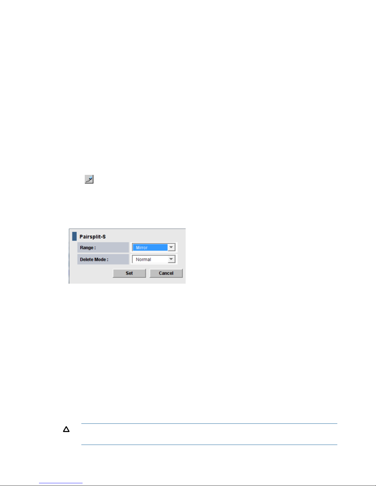
• In a delta resync configuration, if you release the Continuous Access Synchronous pair, the
Continuous Access Journal delta resync pair will be released as well. If you release the
Continuous Access Journal pair, the Continuous Access Journal delta resync S-VOL is released.
• If Continuous Access Journal secondary data volumes are physically attached to the same host
server(s) as the Continuous Access Journal primary data volumes, the following problem can
occur:
When a Continuous Access Journal pair is released, the older, secondary data volume is
usually offline. If the host is then restarted, the system administrator may be offered both
volumes and asked which volume should be left offline. This can be confusing and is prone
to error.
If the Continuous Access Journal secondary data volumes and primary data volumes are
connected to the same host(s), HP strongly recommend that the secondary data volumes are
defined to remain offline to avoid this problem.
To delete a pair or pairs
1. In Remote Web Console, select Actions > Remote Copy > Continuous Access Journal > Pair
Operation.
2. Click to change the mode from View to Modify.
3. In the tree, the port or host group for the pair. Associated pairs display in the right-side list
area.
4. In the list, select the pair or pairs that you want to delete, right-click, and select Pairsplit-S from
the menu. The Pairsplit-S dialog box displays.
5. From the Range list, select one of the following. Note that the Range list is disabled if a pair’s
status is SMPL; In this case, Range is automatically set to LU. If a pair’s status is Deleting or
Suspending, Range is automatically set to Mirror.
• LU, to delete only the selected pair.
• Mirror, (default) to delete all pairs in the same mirror as the selected pairs.
If the following two conditions are satisfied and you select Apply, a warning message
appears and processing cannot continue.
- The Preview list contains two or more pairs belonging to the same mirror.
- The Range column shows Mirror for at least one of the above pairs.
To be able to continue processing, do either of the following:
- Ensure that the Range column shows LU for all pairs in the same mirror.
- In the Preview list, select one pair in one mirror, and then other pairs in the mirror is
excluded.
CAUTION: Do not use the Mirror option when deleting pairs from the secondary system
during disaster recovery.
64 Pair operations
Page 65

6. From the Delete Mode list, select one of the following:
• Normal, to delete the pair or pairs only if the primary system is able to change the pair
status of both P-VOL and S-VOL to SMPL.
• Force, to forcibly delete the pair or pairs, even when the primary system is unable to
communicate with the secondary system. This option could be used, for example, when
the primary system is unable to communicate with the secondary system. Specifying Force
would thus allow host operations to continue.
If Force is specified when pair status is other than SMPL, Range is automatically set to
Mirror.
If Force is specified when Range is set to LU, the other pairs in the same journal are also
suspended.
7. Click Set.
8. See the Preview list to check the settings that you have made.
• If you want to modify a setting, select and right-click the item in the Preview list and then
select Modify.
• If you want to delete a item, select and right-click the item in the Preview list and then
select Delete.
9. Click Apply to apply the settings. If an error occurs, the error code appears in the rightmost
column of the Preview list. To view detailed information about the error, right click the error
code and select Error Detail.
Delete pair volumes from a mirror
When you delete the pairs in a mirror, data copying between master and restore journals end.
Prerequisite information
• This operation can be performed from either the primary or secondary systems.
• When one journal uses two mirror IDs, the result of the operation differs according to the status
of the specified mirror.
◦ When you specify a mirror in Hold, Holding, or Hold(Failure) status, only the Continuous
Access Journal pairs of the specified mirror are deleted.
◦ When you specify a mirror that is not in Hold, Holding, or Hold(Failure) status, Continuous
Access Journal pairs of both mirrors (including the mirror that you did not specify) are
deleted.
To delete pairs from a mirror
1. In Remote Web Console, select Actions > Remote Copy > Continuous Access Journal > Journal
Operation.
2. Click to change the mode from View to Modify.
3. Operate one of the following:
• In the tree, select a master journal or a restore journal from below Registered.
• In the tree, select Journals or Registered and then select a master journal or a restore
journal from the list to the right.
A list of mirrors appears. One row in the list represents one mirror.
4. Select the desired mirror or mirrors.
5. Right-click and select Mirror >Pairsplit-S from the menu.
Delete pair volumes from a mirror 65
Page 66

6. See the Preview list in the Journal Operation window to check the settings that you have made.
If you want to cancel a setting, select and right click the setting and then select Delete.
7. Click Apply to apply the settings. If an error occurs, the error code appears in the rightmost
column of the Preview list. To view detailed information about the error, right click the error
code and select Error Detail.
66 Pair operations
Page 67

7 Monitoring the system
Monitoring pairs, journals, and data paths should be checked frequently to ensure that Continuous
Access Journal pairs are operating correctly. Pair status should be checked before performing a
Continuous Access Journal operation. Each operation requires specific pair status.
Monitor pair activity and status
Monitoring the Continuous Access Journal system is an ongoing operation that should be performed
frequently to maintain your pairs.
• When you want to perform a pair command, first check the pair’s status. Each operation
requires a specific status or statuses.
• Pair-status changes when an operation is performed. Check status to see that pairs are operating
correctly and that data is updated from P-VOLs to S-VOLs in the Paired status (PAIR), or that
differential data management is performed in the Split status (PSUS/PSUE).
Monitoring using the Remote Web Console is done at the user’s discretion. Monitoring should be
repeated frequently. Email notifications of problems can be set up using the Remote Web Console.
For details see HP P9000 Remote Web Console User Guide.
To monitor pair status
1. In Remote Web Console, Click Actions > Remote Copy > Continuous Access Journal > Pair
Operation. The Pair Operation window displays.
2. Click to change the mode from View to Modify.
3. Locate the pair to monitor. Review pair status in the Status column.
4. Select and right click a pair and then select Pair Status from the menu.
You cannot select more than one pair.
5. In the Detailed Information dialog box, view detailed information about the pair.
Pair status definitions
Status descriptions are provided as follows.
S-VOL
access
P-VOL accessDescriptionPair status
Read/WriteRead/WriteThe volume is not assigned to a Cnt Ac-J pair. The volume does
not belong in a journal.
SMPL(simplex)
When a pair is released at the secondary system, S-VOL status
changes to SMPL; the primary system detects this and changes
P-VOL status to PSUS. The pair must be released from the primary
system to change P-VOL status to SMPL.
Read OnlyRead/WriteThe initial copy operation is in progress.COPY
Read OnlyRead/WriteThe pair is synchronized. Updates to the P-VOL are duplicated
on the S-VOL.
PAIR
Read Only,
unless write
Read/WriteThe user has split the pair or released the pair; the pair is no
longer synchronized.
PSUS
option is
enabled.
• The primary and secondary systems keep track of journal data
discarded during the pairsplit operation.
• When the operation is performed at the primary system, the
status of both the P-VOL and S-VOL change to PSUS.
Monitor pair activity and status 67
Page 68

S-VOL
access
P-VOL accessDescriptionPair status
• When the operation is performed at the secondary system,
the status of the S-VOL changes to PSUS; the primary system
detects this (if path status is normal) and changes P-VOL status
to PSUS.
• When a pair is released from the secondary system, the
secondary system changes the status of the S-VOL to SMPL.
The primary system detects this (if path status is normal and
changes P-VOL status to PSUS. (The pair must be released
from the primary system to change P-VOL status to SMPL.)
See “PSUS types and behaviors” (page 71) for PSUS types.
Read OnlyRead/write;
Read only if
fenced.
The pair is suspended due to an error; the pair is not
synchronized.
PSUE
• The primary and secondary systems keep track of any journal
data that are discarded during the suspension operation.
• The primary system keeps track of P-VOL tracks that are
updated while the pair is suspended.
• When a Cnt Ac-J suspension condition is detected, the primary
system changes P-VOL and S-VOL status to PSUE. If the
secondary system detects the condition, it changes the S-VOL
status to PSUE; the primary system detects this and changes
P-VOL status to PSUS.
See “PSUE types and behaviors” (page 72)for PSUE types.
Read OnlyRead/WriteThe pair is not synchronized. The pair is in transition to
PSUS/PSUE.
Suspending
Read OnlyRead/WriteThe pair relationship is being deleted. When the operation is
completed, status changes to SMPL.
Deleting (releasing)
68 Monitoring the system
Page 69

S-VOL
access
P-VOL accessDescriptionPair status
Read/Write
*2
Read/Write
*1
HOLD
• The pair or command devices are ready for the delta resync
operation. When the status of the Cnt Ac-J P-VOL is HOLD,
incoming write data for the Cnt Ac-S S-VOL is stored in the
master journal volume.
• Operations allowed on the pairs in HOLD status:
- Delta resync
- Pair-delete
- Changing pair options
-Read/Write
*1
The pair status is changing to Hold so that the delta resync pair
can be created.
HOLDING *
4
If you execute the delta resync operation on the pair in HOLDING
status, the operation may fail. If you set Entire for the field, Delta
resync Failure, on the Change Journal Option dialog box,
differential data will be copied to a S-VOL.
The only operations allowed for this status are:
• Delta resync operation
• Pair release
• Changing the pair option
-Read/Write
*1
HLDE
• An error occurred on the pair in HOLD status.
• When the status of P-VOL is HLDE, incoming write data for
the Cnt Ac-S S-VOL is not stored in the master journal volume.
• Operations allowed on pairs in HLDE status are:
- Recovering pair status to standby (HOLD)
- Pair-delete
- Changing pair options
Other pair statuses in RAID Manager are provided as follows:
S-VOL
access
P-VOL accessDescriptionPair status
Read OnlyRead/Write
*3
If data in the journal volume exceeds 80%, pair status changes
to PFUL. The write data that inflows then is monitored during the
Data Overflow Watch.
PFUL
PFUL status is displayed by RAID Manager. Remote Web Console
displays this status as PAIR.
Read Only,
unless write
Read/Write
*3
If the Data Overflow Watch period is exceeded, pair status
changes from PFUL to PFUS, and the pair is suspended.
PFUS
option is
enabled.
• The PFUS status is displayed by RAID Manager and Remote
Web Console as PSUS.
• If a virtual volume of Thin Provisioning (V-VOL) is used as a
Cnt Ac-J S-VOL, and the capacity of a pool-VOL is nearly full,
Cnt Ac-J status becomes PFUS and the pair is suspended.
Read/WriteRead OnlyAfter Takeover, SSWS is the status of the S-VOL. With this status,
data can be written to the S-VOL.
SSWS
• SSWS is displayed by RAID Manager, from which the
horctakover command is issued.
• Remote Web Console displays this status as PSUS or PSUE.
*1: Accessing the P-VOL depends on the status of the Cnt Ac-S pair that shares the volume.
Monitor pair activity and status 69
Page 70

S-VOL
access
P-VOL accessDescriptionPair status
*2: The Cnt Ac-J S-VOL in HOLD status uses two mirrors. Accessing the S-VOL depends on the status of the mirror
whose status is not HOLD.
*3: A host cannot write data to the Cnt Ac-J P-VOL when it belongs to a journal that was registered when 2DC Cascade
is set to Enable in the Edit Journal Volume dialog box.
*4: HOLDING indicates either that differential data used for a delta resync operation does not exist, or that the storage
system cannot judge whether the delta resync can be performed without the differential data.
When differential data does not exist in the secondary Cnt Ac-S site, even after the S-VOL is updated, it is possible
that the differential data was discarded due to the one of the following:
• The cache or shared memory was added to or removed from the storage system during maintenance work.
• The storage system was powered off during maintenance work.
• The Cnt Ac-J or Cnt Ac-S pair was suspended and then resynchronized.
After the system is back to normal, differential data are stored again in the Cnt Ac-S S-VOL if you update the data in
the primary site.
The delta resync operation can be executed without differential data if data update to the primary site is not executed
or data in the Cnt Ac-S S-VOL and the Cnt Ac-J S-VOL are the same because the data update stopped.
To make the above mentioned condition, make the configuration to execute the delta resync operation to support the
remote command devices, and then change the status of all Cnt Ac-J pair and Cnt Ac-S pair which belong to the desired
journal in the primary site to PAIR by the resynchronizing operation.
Even if the "delta resync operation" without the differential data is executable, the pair status will change to HOLD
regardless of the differential data existing if the conditions of the differential data discarding are satisfied as mentioned
above. To change the status of the pair to HOLD, update the data in the primary disk system after the recovery from
the condition of the differential data discarding.
If you cannot connect to the secondary site of Cnt Ac-S due to failures or disasters, the transition from HOLDING to
HOLD is not performed correctly.
Additional information on pair status
• When a pair is split or suspended, the primary system notifies the host(s) with a service
information message (SIM). If SNMP is installed and operational for P9500, this SIM results
in an SNMP trap indicating the reason for suspension.
• Transitional statuses occur when a request to change Continuous Access Journal pair status
to PSUS, PSUE, or SMPL has been accepted, but is not complete. Transition states are not
reported to the host.
• The user and the primary or secondary systems can initiate the PSUS / PSUE status change.
• Only the user can perform delete a pair.
• If a user performs an operation, the final status is reported at the end of the operation.
• If an error causes the status to change to PSUE, the status is reported at the beginning of the
transition.
• A pair in Flush mode (remaining local update data is flushing to the secondary system) remains
in Suspending or Deleting status until data in the master and restore journals is the same and
the pair is completely split or released. To calculate the time during which the pair remains
Suspending or Deleting, use the following equation:
C x (u / 100) x 1,024 / V (The unit is seconds)
where:
◦ C is total capacity (MB) of the master journal volume.
◦ u is the usage rate of data (%) in the master journal volume.
◦ V is data transfer speed (MB/sec) between the primary and the secondary systems.
70 Monitoring the system
Page 71

See “Usage Monitor window ” (page 177) for instructions on viewing the usage rate of a journal
volume.
• When the pair status is COPY, you cannot add cache or shared memory to or remove it from
the storage system. Before performing either of these tasks, split any pairs with COPY status,
and then resynchronize the pairs when the cache or shared memory operation is complete.
PSUS types and behaviors
The PSUS status can be initiated by the user or the system, from the primary or secondary systems.
DescriptionVolume PSUS type applies
to
PSUS type
The user split the pair from the primary or secondary system,
using the S-VOL write option. RAID Manager displays this PSUS
type as SSWS.
P-VOL, S-VOLPSUS, S-VOL by Operator
S-VOLPSUS, by MCU
• The secondary system received a request from the primary
system to split the pair.
• The P-VOL PSUS type is PSUS-S-VOL by Operator.
• RAID Manager displays this PSUS type as SSUS or SSWS.
P-VOL, S-VOLPSUS, by RCU
• The primary system suspended the pair after detecting an
error condition at the secondary system.
• The S-VOL suspend type is PSUE-S-VOL Failure.
The primary system detected that S-VOL status is SMPL after the
user released the pair from the secondary system. The pair
cannot be resumed.
P-VOLPSUS, Pairsplit-S to RCU
The pair was suspended because the journal volume was near
capacity.
• RAID Manager displays this PSUS type as PFUS or SSWS.
P-VOL, S-VOLPSUS, JNL Cache
Overflow
• A pair can be split after the initial copy is complete.
• A pair must be split to perform maintenance on the P-VOL, or to enable write-access on the
S-VOL.
• After status changes to PSUS, the primary system performs the following tasks:
Stops journal-obtain operations◦
◦ Continues to accept write I/Os from host to P-VOL
◦ Keeps track of updated P-VOL tracks
• If you enable the S-VOL write-option when splitting the pair, the secondary system keeps track
of updated S-VOL tracks. When the pair is resynchronized, the secondary system sends the
S-VOL track bitmap to the primary system, which then merges P-VOL and S-VOL bitmaps to
synchronize the tracks.
• A split or suspended S-VOL has a separate consistency status, which indicates the S-VOL’s
update sequence consistency with respect to the other S-VOLs in the associated journal.
Consistency status displays on the secondary system only. S-VOL consistency statuses are
described below.
Monitor pair activity and status 71
Page 72

Table 8 S-VOL consistency statuses
DescriptionConsistency status
Volume
• Only the current pair was split or suspended.
• Update sequence consistency between this S-VOL and other S-VOLs in the associated
journal is not insured.
• This S-VOL cannot be used for disaster recovery at the secondary site.
• This status is indicated when:
- The pair is split by the user using the Suspend Range-Volume (LU) pairsplit option.
- The pair is suspended due to a failure that did not affect the entire journal.
Mirror
• The pair was split or suspended along with the other pairs in the associated mirror.
• Update sequence consistency between this S-VOL and other S-VOLs in this mirror is
insured.
• This S-VOL can be used for disaster recovery on the secondary system.
• This status is indicated when:
- The pair is split by specifying mirror of the pairsplit -r option.
- All pairs in the associated mirror are suspended due to a failure that affects the entire
group; for example, path failure.
- One pair in the mirror was suspended due to a failure that did not affect the entire
group.
PSUE types and behaviors
The primary system suspends a pair and changes its status to PSUE when it detects any of the
following:
• The user has released the pair on the secondary system.
• An error condition related to the secondary system, S-VOL, or an update operation.
• The primary system is unable to communicate with the secondary system.
• A Continuous Access Journal suspension condition is detected by the system.
The following describes the types of PSUE status.
DescriptionVolume PSUE Type
Applies To
PSUE Type
The primary system detected an error during communication with the
secondary system or during update copying.
P-VOL, S-VOLPSUE, S-VOL
Failure
S-VOL PSUE type is usually PSUE-S-VOL Failure.
RAID Manager might display this PSUE type as SSWS.
The primary system could not find valid control information in its nonvolatile
memory during IMPL (Initial Microprocessor Mode). This condition occurs
P-VOL, S-VOLPSUE, MCU IMPL
if the primary system is without power for more than 48 hours (power
failure and fully discharged backup batteries).
The pair was suspended before the initial copy operation was complete.
The data on the S-VOL is not identical to the data on the P-VOL.
P-VOL, S-VOLPSUE, Initial Copy
Failed
RAID Manager might display this PSUE type as SSWS.
The primary system is powered off.S-VOLPSUE, MCU P/S
OFF
RAID Manager displays this PSUE type as SSUS.
72 Monitoring the system
Page 73

When a pair is suspended, the primary system stops performing journal-obtain operations for the
pair. However, the primary system continues the following operations:
• Continues accepting write I/Os for the suspended P-VOL
• Keeps track of the P-VOL cylinders/tracks that are updated
• Keeps track of journal data discarded during the pair suspension. (Both primary and secondary
systems do this.)
A split or suspended S-VOL has a separate consistency status that indicates its update sequence
consistency with respect to the other S-VOLs in the associated journal. Consistency status displays
on the secondary system only. Table 8 (page 72) describes S-VOL consistency statuses.
When the pair is resynchronized, the primary and secondary systems perform the following
operations:
• The secondary system sends the S-VOL bitmap to the primary system
• The primary system merges the P-VOL and S-VOL bitmaps to synchronize the tracks
These actions insure that all cylinders/tracks containing journal data discarded on the secondary
system are resynchronized.
Filtering Information in the List in the Pair Operation window
Use the Display Filter dialog box to filter information in the list in the Pair Operation window. The
list shows only the volumes that satisfy certain conditions.
To filter information in the list in the Pair Operation window
1. In the Pair Operation window, click Display Filter.
2. Use the Display Filter dialog box to specify information that you want to display in the list.
3. Click Set to close the Display Filter dialog box. The list in the Pair Operation window displays
the specified information only.
To restore the list to the default status (i.e., the status before filtering), click Reset in the Display
Filter dialog box and then Set in the same dialog box.
If you change settings in the Display Filter dialog box, the changes remain in effect during the
session until you reset the settings.
The Display Filter dialog box shows the following:
• GID: Select the group number of a host group to be displayed. If you select All, all host groups
display in the list.
• Journal: Select the journal to be displayed. If you select All, all journals display in the list.
• Mirror: Select the mirror to be displayed. If you select All, all mirrors display in the list.
• P-VOL/S-VOL: Select the type of volumes to be displayed.
If you select P-VOL, P-VOLs display in the list.
If you select S-VOL, S-VOLs display in the list.
If you select All, all P-VOLs and all S-VOLs display in the list.
• CLPR: Select the CLPR to be displayed. If you select All, all CLPRs display in the list.
• Internal/External VOL: Specify whether internal volumes or external volumes display in the
list. If you select All, all the internal and external volumes display in the list.
• Status: Allows you to specify pair statuses. The volumes of the specified statues display in the
list.
• Reset: Restores all options in the Display Filter dialog box to the default state. All the lists show
All and all the check boxes are selected.
Monitor pair activity and status 73
Page 74

• Set: Applies the settings in the Display Filter dialog box to the list.
• Cancel: Discards the settings and closes the dialog box.
Saving pair status information into a text file
You can use the export function only while the client file access is enabled. When the client file
access is not enabled, the Export is not available on the Pair Operation window. For the further
information of the client file access settings, see HP P9000 Remote Web Console User Guide.
Following information of pair is described in the exported file:
DescriptionItem
Port in the local storage system.Port
Group number and name of host group in the local storage system. (The name is limited to a
maximum of 16 characters.)
Gr(Name)
LU number in the local storage system.LUN
LDKC number, CU number and LDEV number in the local storage system.Vol
Status of the pair.Status
Journal number in the local storage system.JNL
Mirror ID.Mr
Serial number of the remote storage system.S/N(LDKC)
Controller ID and model name of the remote storage system.CNTL
Port number in the remote storage system.Port
Group number of host group in the remote storage system.Gr
LU number in the remote storage system.LUN
LDKC number, CU number and LDEV number in the remote storage system.Vol
Journal number in the remote storage system.JNL
Type of volumes in the local storage system.Type
Consistency group number of RAID Manager.CTG
Error level.ErrLv
Progress of copy operation. Or, synchronization rate (that is, concordance rate) between the
data volume before the pair was split and the data volume after the pair was split.
Sync
CLPR number and CLPR name.CLPR
Copy timeCopyTime
An LDEV number ending with # indicates the volume is an external volume. For detailed information
about external volumes, see HP P9000 External Storage for Open and Mainframe Systems User
Guide.
A device ID ending in X (e.g., 00:00:3C X) indicates the LDEV is a Thin Provisioning virtual volume.
For details on a virtual volume, see HP P9000 Provisioning for Open Systems User Guide.
"00" appears as the LDCK number when the volume is a volume of XP12000 Disk Array/XP10000
Disk Array and XP24000/XP20000 Disk Array.
To save information about pairs in a text file
1. If necessary, filter information in the list in the Pair Operation window.
74 Monitoring the system
Page 75
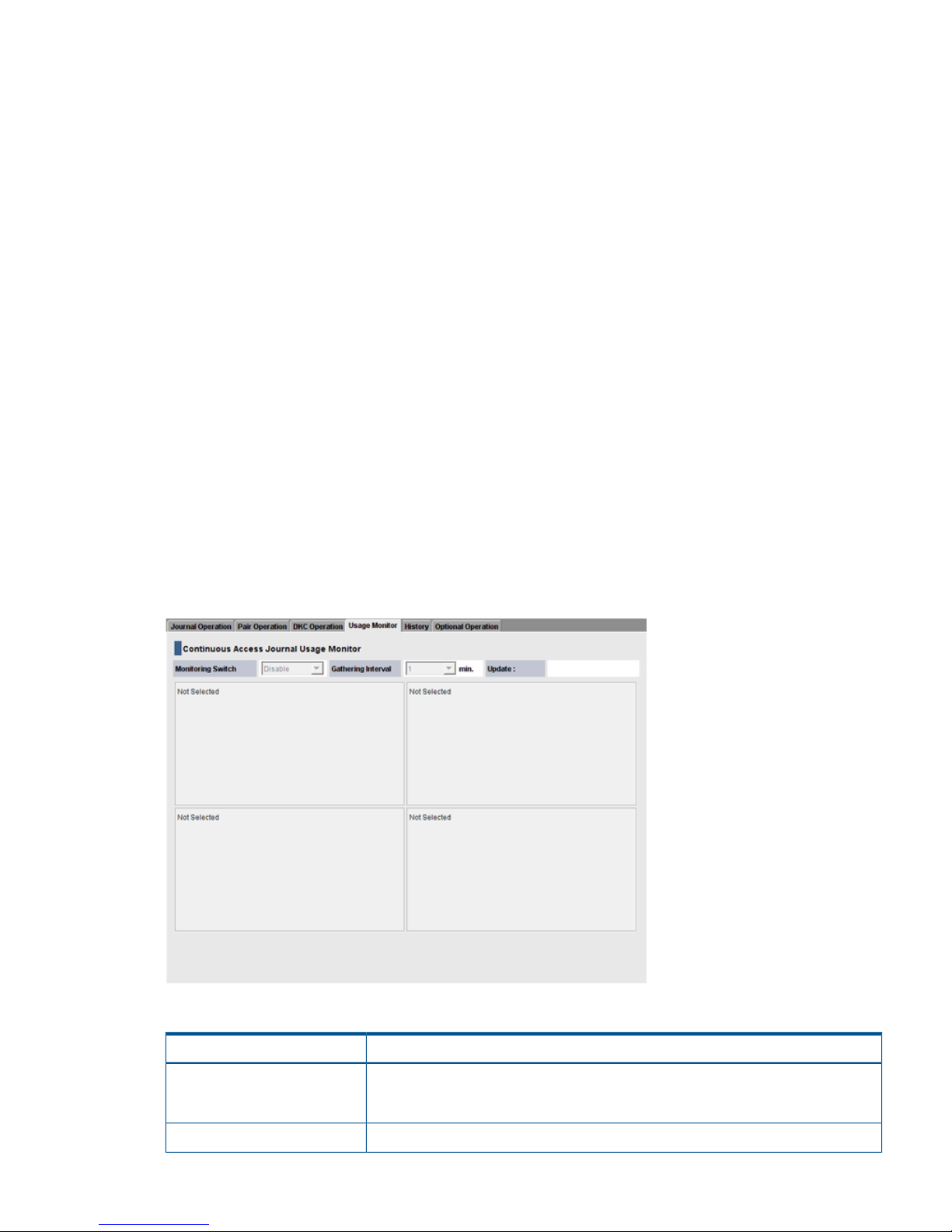
2. In the Pair Operation window, click Export. A message appears and asks whether to save
volume pair information in a file.
3. Click OK to close the message.
A dialog box appears and prompts you to save a file.
4. Enter the name of the file and then click Save.
A message appears.
5. Click OK to close the message.
If Subsystem or an LDKC is selected in the tree, you can abort the exporting by clicking Cancel
in the dialog box that is open during the export processing.
Monitor copy operations data, I/O
You can monitor and use data for remote copy operations data and I/O statistics for monitored
volumes on the storage system in the Usage Monitor window.
This chapter shows you how to do the following:
• “Select data to be graphed” (page 76)
• “Manipulate graph, save data” (page 78)
In Remote Web Console, click Actions > Remote Copy > Continuous Access Journal > Usage Monitor.
The Usage Monitor window displays as shown in Figure 16 (page 75). The fields on the Usage
Monitoring window are described in Table 9 (page 75).
You start and stop monitoring in Performance Monitor. See HP P9000 Performance for Open and
Mainframe Systems User Guide for instructions.
Figure 16 Usage Monitor Window
Table 9 Fields on the Usage Monitor window
DescriptionField
Monitoring Switch
• Enable: Monitoring is on. Graph displays.
• Disable: Monitoring is off. Graph is disabled.
The data collection interval.Gathering Interval
Monitor pair activity and status 75
Page 76

Table 9 Fields on the Usage Monitor window (continued)
DescriptionField
The most recent data sample time of data on the graph.Update
Remote I/O statistics and status of remote copy monitor.Usage Monitor Graph
Select data to be graphed
The usage monitor graph plots the I/O data that you specify. On the graph:
• The x-axis indicates time.
• The y-axis indicates the number of I/Os during the sampling period.
• The legend on the right side shows the data being displayed.
The value on the y-axis varies according to the maximum value of the statistical data appearing
in the graph. If the y-axis value exceeds 10,000,000, the value is shown in exponential notation
(for example, 1E7 = 1 x 107 = 10,000,000; 2E8 = 2 x 108 = 200,000,000).
To specify I/O data to be graphed
1. Make sure that usage monitoring is running (Monitoring Switch = Enable). The usage monitor
graph can be viewed only when monitoring is on.
2. Right-click the graph and select Display Item from the menu that appears. The Display Item
dialog box displays.
3. In the Select Volume box, select one of the following:
• ALL Volumes, to view I/O statistics for all LDEVs in the system. When selected, the LDKC
number, CU number, and LDEV number appear above the graph.
- A device ID ending in # (e.g., 00:00:3C #) indicates the LDEV is an external volume
(see HP P9000 External Storage for Open and Mainframe Systems User Guide for more
information about external drives).
- A device ID ending in X (e.g., 00:00:3C X) indicates the LDEV is a Thin Provisioning
virtual volume (see HP P9000 Provisioning for Open Systems User Guide for more
information on a virtual volumes).
• Journal, to view I/O statistics for a specific journal. Enter a journal number (000-0FF) in
the Journal box.
• Volume, to view I/O statistics for a specific LU. Select the LU Port (CL1-A to CLG-R) and
enter the GID (00-FE) and LUN (000-7FF).
4. In the Monitor Data boxes, select the I/O statistics data that you want to appear on the graph.
You must select at least one box. Table 10 (page 77) describes the I/O statistics data.
76 Monitoring the system
Page 77

5. Click Set to close the Display Item dialog box. The Usage Monitor window now shows a graph
of the selected I/O statistics data for the selected LU(s).
Table 10 Remote copy I/O statistics data
DescriptionData type
Host I/O
The number of write I/Os per second.Write Record Count
The amount of data that are written per second. The unit is kilobytes per
second.
Write Transfer Rate
Initial Copy
The initial copy hit rate. The unit is percent.Initial Copy Hit Rate
The average transfer rate for initial copy operations. The unit is kilobytes
per second.
Average Transfer Rate
Asynchronous Copy
The number of asynchronous remote I/Os per second at the primary storage
system.
M-JNL Asynchronous RIO count
The number of journals at the primary storage system.M-JNL Total Number of Journal
The average transfer rate for journals in the primary storage system. The
unit is kilobytes per second.
M-JNL Average Transfer Rate
The remote I/O process time on the primary storage system. The unit is
milliseconds.
M-JNL Average RIO Response
The number of asynchronous remote I/Os per second at the secondary
storage system.
R-JNL Asynchronous RIO count
The number of journals at the secondary storage system.R-JNL Total Number of Journal
Monitor pair activity and status 77
Page 78

Table 10 Remote copy I/O statistics data (continued)
DescriptionData type
The average transfer rate for journals in the secondary storage system.
The unit is kilobytes per second.
R-JNL Average Transfer Rate
The remote I/O process time on the secondary storage system. The unit is
milliseconds.
R-JNL Average RIO Response
M-JNL
Data usage rate for master journals. The unit is percent.Data Used Rate
Metadata usage rate for master journals. The unit is percent.Meta Data Used Rate
R-JNL
Data usage rate for restore journals. The unit is percent.Data Used Rate
Metadata usage rate for restore journals. The unit is percent.Meta Data Used Rate
Manipulate graph, save data
• To enlarge the graph, right-click it and select Large Size.
• To close the graph, right-click it and select Close.
• To save monitoring data in text files, use the Performance Monitor Export Tool.
Monitor journal (mirror) status
The status of a mirror associated to a Journal relates to pair operations performed on the journal.
Monitoring these statuses can help you resolve problems and maintain the Continuous Access
Journal system. The status of a mirror associated to a Journal is viewed on the Journal Operation
window.
This section explains how to navigate to the Journal Operation window and provides definitions
for statuses.
To view journal status
1. In Remote Web Console, select Actions > Remote Copy > Continuous Access Journal > Journal
Operation.
2. In the tree, expand Registered then select the desired LDKC. Journals display in the tree and
mirrors display in the right-side pane.
See the status field.
Mirror status definitions
DescriptionStatus
Journal volumes are registered in the journal but data volumes are not registered.
Initial
The journal has Cnt Ac-J pairs that are synchronized, or the initial copy is in progress.
Active
If a journal in Active status contains pairs that are split, a warning appears. The split pairs must
be resynchronized.
The status at the beginning of a mirror-split operation. The status changes immediately to Halting.
HaltAccept indicates status of restore journals only.
HaltAccept
78 Monitoring the system
Page 79

DescriptionStatus
An operation for splitting or deleting the mirror is in progress.
Halting
• Splitting a mirror changes the status in the following order: Halting, Halt, Stopping, and finally
Stopped.
• Deleting a mirror changes the status in the following order: Halting, Halt, Stopping, Stopped,
and finally Initial.
An operation for splitting or deleting the mirror is in progress.
Halt
An operation for splitting or deleting the mirror is in progress.
Stopping
An operation for splitting or deleting the mirror is finished.
Stopped
A Cnt Ac-J delta resync pair has been created. It is ready for the delta resync operation.
Hold
A Cnt Ac-J delta resync pair is being created.
Holding
An error occurred with the Cnt Ac-J pair during the delta resync operation.
Hold(Failure)
This is the unused journal which is not registered data volumes.Blank
Monitor logical path status
To view logical path status
1. In Remote Web Console, select Actions > Remote Copy > Continuous Access Journal > DKC
Operation.
2. In the Display box, select DKC and select LDKC.
3. Locate the remote system in the list on the right side and view the Status column.
4. To see in-depth path status, right-click the remote system and select DKC Status.
DescriptionItem
Number of the row.No
Status of a logical path.Path Status
• Normal. The path is established and ready to use for copy operations.
• Nothing. An operation for configuring or deleting the path is in progress.
• Initialization Failed. An error occurred when the connection between local and remote
systems was initializing. The probable causes are:
- No cable is connected to the local system.
- No cable is connected to the remote system.
- No cable is connected to the network device between the two systems.
• Communication Time Out. This status indicates one of the following:
- A timeout error has occurred between the primary and the secondary storage systems.
- A logic error is detected between the primary and the secondary storage systems.
• Resource Shortage (Port). The local system rejected configuration of the logical path
connection. Logical path resources in the local system might be in use for other connections.
• Resource Shortage (Pair-Port). The remote system rejected configuration of the logical path
connection. Logical path resources in the remote system might be in use for other connections.
• Serial Number Mismatch. The serial number of the storage system connected to this logical
path does not match the serial number specified by the Add DKC dialog box.
• Invalid Port. The port is not an initiator port.
• Pair-Port Number Mismatch. Indicates one of the following:
- The specified port number is incorrect.
Monitor logical path status 79
Page 80

DescriptionItem
- The port in the remote system is physically disconnected from the local system.
• Pair-Port Type Mismatch. The port on the remote system is not an RCU target port.
• Communication Failed. A communication timeout error has occurred on the path between
the local and remote systems.
Port on the local system.Port
Port on the remote system.Pair-Port
Serial number and LDKC number of the remote system.S/N
Controller ID and model name (in parenthesis) for the remote system.Controller ID
Path group IDPath Gr. ID
Type of channel interface between local and remote systems. Always displays column displays
“Fibre”.
M-R Path
Minimum possible number of paths between the local and the remote systems.Minimum Paths
Remote I/O missing interrupt handler timer value—the wait time for data transfer from the local
to remote system to complete.
RIO MIH
Date and time when local and remote systems were associated to each otherDKC Registered
Date and time the last operation on a logical path to the remote system was performed.Last Updated
When clicked, the DKC Operation window refreshes when it redisplays.Refresh the DKC
Operation tab after
this panel is closed
History of operations for data volume pairs
The History window provides the history of operations for data volume pairs. For example, the
window shows the date and time when data volume pairs are created or released.
To open the History window, do either of the following:
If Continuous Access Journal has not been started:
1. In Remote Web Console, select Actions > Remote Copy > Continuous Access Journal > History.
The History window opens. The History window may not show the latest operation history.
To view the latest operation history, go to the next step.
2. Select File > Refresh. The operation history is updated.
If Continuous Access Journal has already been started:
1. Click the History tab to open the History window.
The History window may not show the latest operation history. To view the latest operation
history, go to the next step.
2. Select File > Refresh. The operation history is updated.
80 Monitoring the system
Page 81

8 Maintaining the system
Some maintenance tasks are a response to behavior discovered during system monitoring. However,
you can also change certain settings to keep the system in tune with your changing requirements.
Pair maintenance—change the pair-split option
You can change the option that specifies whether a pair-split operation that is triggered by pair
failure is applied to all the pairs in the mirror, or only to the affected pair. This option was first set
during the pair create operation.
Prerequisite information
You can change this option only for pairs in PAIR, PSUS, PSUE, HOLD, HOLDING, or HLDE status.
To change the option
1. In Remote Web Console, select Actions > Remote Copy > Continuous Access Journal > Pair
Operation.
2. Click to change the mode from View to Modify.
3. In the tree, select the port that you have configured for the pair, or a host group (displayed
below the ports). The volumes for the port or host group display in the right-side list area,
4. In the list, right-click the desired pair, or mirror of pairs, then select Change Pair Option from
the menu.
NOTE: If you selected multiple pairs and want to change one of the options on the Change
Pair Option dialog box – but do not intend to change the other option, leave blank the option
that you do not want to change.
5. In the Change Pair Option dialog box, click the Error Level list and select one of the following:
• Mirror, to cause all pairs in the failed pair’s mirror to be split.
• LU, to cause only the pair that failed to be split.
6. Click Set when finished.
7. See the Preview list to check the settings that you have made.
• If you want to modify a item, select and right click the setting in the Preview list and then
select Modify.
• If you want to cancel a item, select and right click the setting and then select Cancel.
8. Click Apply to apply the settings. If an error occurs, the error code appears in the rightmost
column of the Preview list. To view detailed information about the error, right click the error
code and select Error Detail.
Journal and mirror maintenance
Maintaining journals and mirror consists of the following operations:
• Changing journal options
• Changing mirror options
• Deleting journal volumes from journals
• Deleting journals
Pair maintenance—change the pair-split option 81
Page 82

Change Continuous Access Journal options used by journals
Most Continuous Access Journal pair operations are performed on multiple pairs. This is done
using journals. You can change the following options that affect the pairs in journals:
• Inflow Control—allows you to restrict the inflow of data to allow other journals with higher
priority data unrestricted inflow
• Data Overflow Watch—establishes a timeout period
• Use of Cache—which enables using store journal data in the cache on the secondary system
Prerequisite information
Please be aware of the following when changing journal options:
• Journal options must be changed on both systems, primary and secondary.
• To change journal options, one of the following conditions must be satisfied:
- The attribute of the journal is Initial.
- The status of the journal in the mirror is one of the following:
◦ Initial
◦ Stopped
◦ Hold(Failure)
When one journal uses multiple mirrors, whether you can select Change Journal Option
depends on the status of the journal whose mirror is not in Hold, Holding or Hold(Failure)
status. For example, if mirrors in the journal are in the Hold and Active status, you can not
change the journal option. If mirrors in the journal are in the Hold and Stopped status, you
can change the journal option.
• When changing options for multiple journals, you can leave some options unchanged by
entering or selecting no value. If you specify a value, it is applied to the selected journals.
To change options for a journal
1. In Remote Web Console, select Actions > Remote Copy > Continuous Access Journal > Journal
Operation. The Journal Operation window displays.
2. Click to change the mode from View to Modify.
3. Operate either of the following:
In the tree, right click a journal from below Registered and then select Journal > Change
Journal Option.
In the upper right list, right click the desired journal and then select Journals > Change Journal
Option.
82 Maintaining the system
Page 83
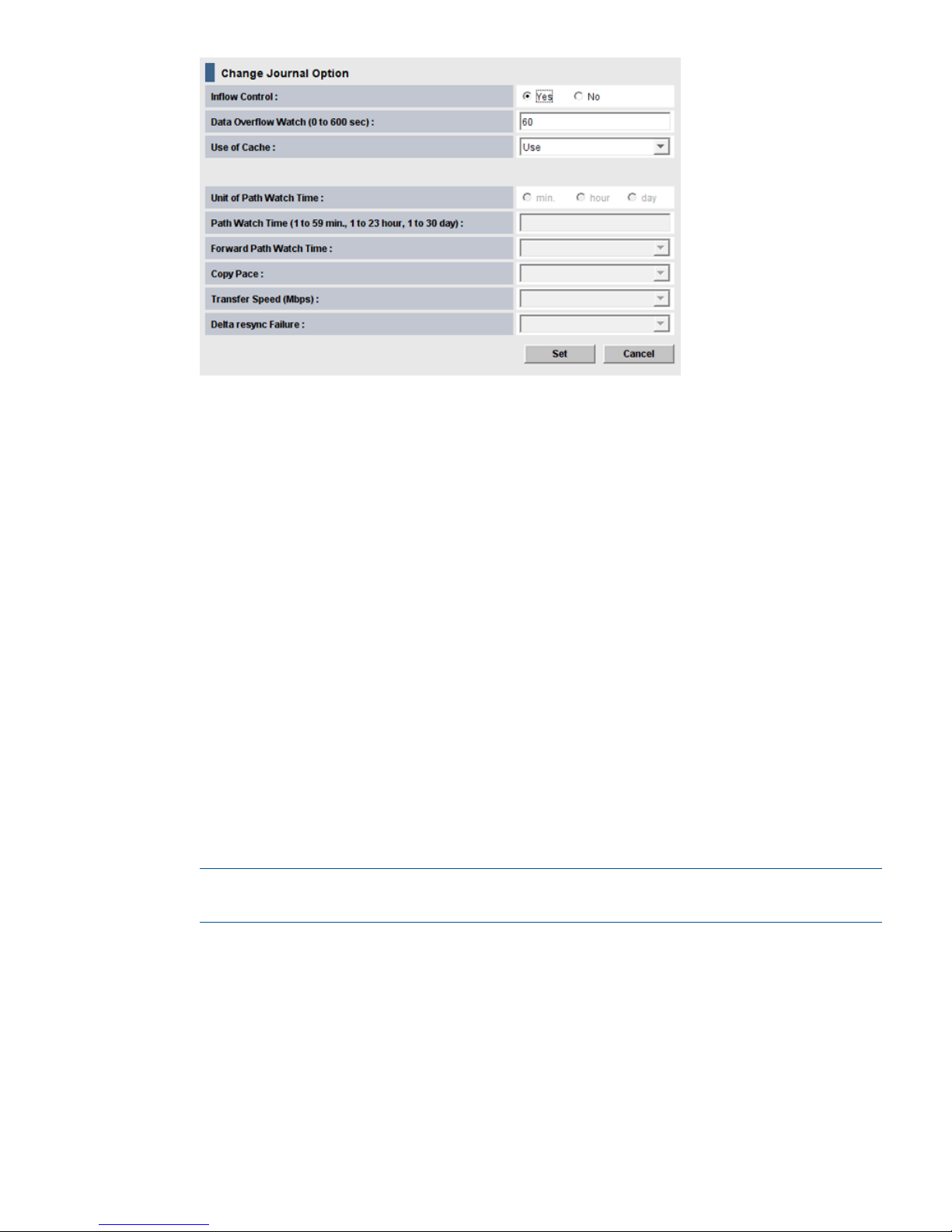
4. For Inflow Control, specify whether to restrict inflow of update I/Os to the journal volume
(slows delay response to hosts).
For example, you could have a 100 GB-bandwidth data path with three journals using it. If
an important database is saved to a primary volume in one of the journals, with data of lesser
importance in the other journals, you may decide to restrict the Inflow Control for the less
important journals while not restricting control to the important journal.
Yes indicates inflow will be restricted. No indicates inflow will not be restricted.
If Yes is selected and the metadata or the journal data is full, the update I/Os may stop.
5. For Data Overflow Watch, specify the number of seconds for the system to monitor write data
to the journal volume when the journal volume threshold (80%) is reached. Range is 0-600
seconds. Default is 60 seconds. See status definitions for PFUL and PFUS in “Pair status
definitions” (page 67) for more information.
If Inflow Control is No, Data Overflow Watch is disabled.
6. For Use of Cache, specify whether to store journal data (initial copy or resynchronization data)
in the cache memory on the remote side (restore journal).
- Use: Journal data will be stored in the cache. When there is insufficient space in the cache,
journal data will also be stored into the journal volume. This setting only takes effect on the
journal volumes of RAID-5 or RAID-6.
Not Use: Journal data is not stored in the cache.
- Blank: The current setting of Use of Cache will remain unchanged.
NOTE: This setting does not effect master journals unless the RAID Manager horctakeover
command is used to change a master journal into a restore journal.
7. Click Set when finished.
8. See the Preview list in the Journal Operation window to check the settings that you have made.
• If you want to modify a item, select and right click the setting in the Preview list and then
select Modify.
• If you want to cancel a item, select and right click the setting and then select Cancel.
9. Click Apply to apply the settings. If an error occurs, the error code appears in the rightmost
column of the Preview list. To view detailed information about the error, right click the error
code and select Error Detail.
Journal and mirror maintenance 83
Page 84

Change Continuous Access Journal options used by mirrors
Most Continuous Access Journal pair operations are performed on multiple pairs. This is done
using a journal or mirrors. You can change the following options that affect the pairs in a mirror:
• Unit of Path Watch Time—establishes the unit of path watch time.
• Path Watch Time—establishes the amount of time before a blocked path results in the mirror
being split.
• Forward Path Watch Time—establishes whether to forward the Path Watch Time value of the
master journal to the restore journal.
• Copy Pace—establishes the pace at which data is copied.
• Transfer Speed—which specifies the speed for data transfer.
• Delta Resync Failure—which specifies the processing that takes place in the event of a failure.
Prerequisite information
Please be aware of the following when changing mirror options:
• mirror options can be changed on the primary storage system and secondary storage system.
• To change mirror options, the status of the mirror is one of the following:
Initial◦
◦ Active
◦ Stopped
◦ Hold
◦ Holding
◦ Hold(Failure)
• The Transfer Speed option can be changed if the mirror’s status is Active, Hold, or Holding.
• When changing options for multiple mirrors, you can leave some options unchanged by
entering or selecting no value. If you specify a value, it is applied to the selected mirrors.
To change options for a mirror
1. In Remote Web Console, select Actions > Remote Copy > Continuous Access Journal > Journal
Operation. The Journal Operation window displays.
2. Click to change the mode from View to Modify.
3. Operate either of the following:
In the upper right list, right click the desired journal and then select Mirror > Change Mirror
Option.
84 Maintaining the system
Page 85
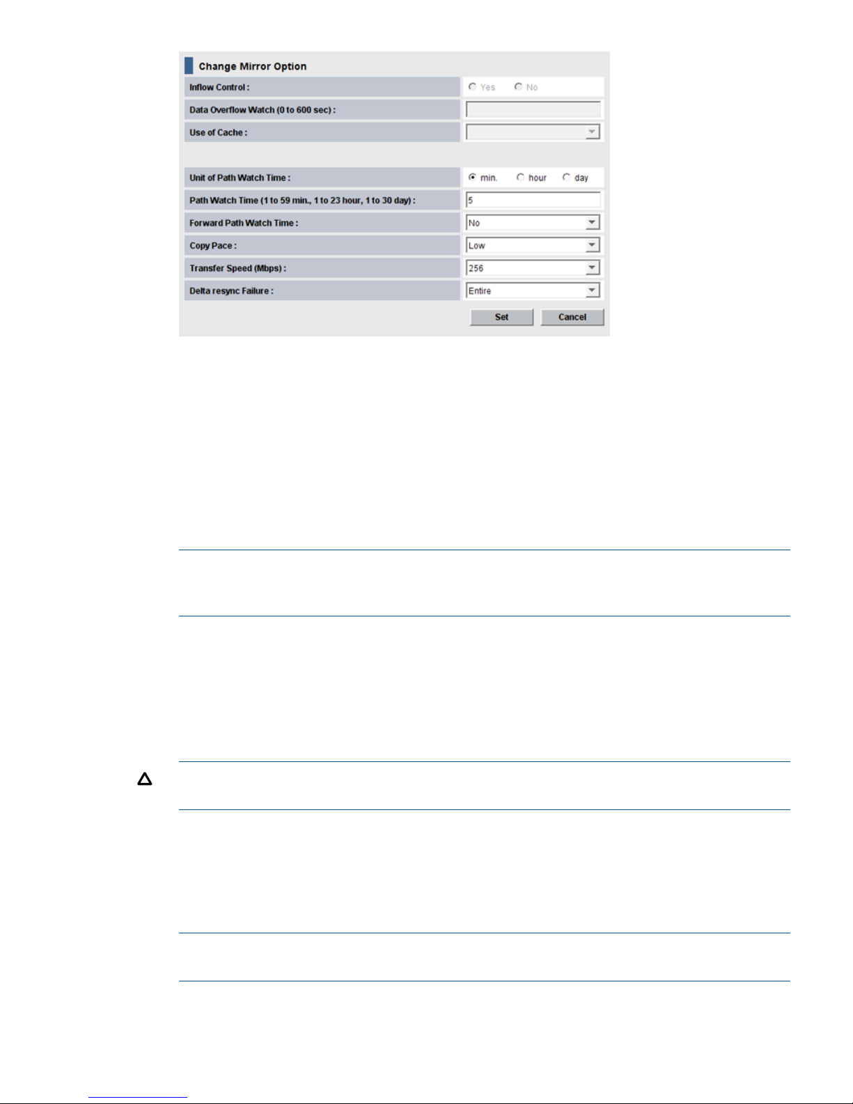
4. For Copy Pace, specify the pace for initial copy activity per volume. This field cannot be
specified on the remote system. Low is the default. When specifying Medium, insure that write
I/O is 10 MB/s or less per parity group. If it exceeds 10 MB/s, pairs may be suspended.
When specifying High, insure that I/O will not occur. If update I/O occurs, pairs may be
suspended.
5. For Unit of Path Watch Time, specify the unit of time for Path Watch Time, minute, hour, or
day.
6. For Path Watch Time, specify the interval from the time a path becomes blocked to when the
mirror is split (suspended). The interval must be the same for master and restore journals in
the same mirror (see next item).
NOTE: If you want a mirror to split immediately after a path becomes blocked, ask HP
Technical Support to set system option mode 448 to ON and set system option mode 449 to
OFF.
7. For Forward Path Watch Time, specify whether to forward the Path Watch Time value of the
master journal to the restore journal. If the Path Watch Time value is forwarded from the master
journal to the restore journal, the two journals will have the same Path Watch Time value.
- Yes: The Path Watch Time value will be forwarded to the restore journal.
- No: The Path Watch Time value will not be forwarded to the restore journal. No is the default.
- Blank: The current setting of Forward Path Watch Time will remain unchanged.
CAUTION: This option cannot be specified in the secondary storage system. For a pair using
the delta resync configuration, select Yes in the primary storage system.
8. For Transfer Speed, specify the line speed (in Mbps (megabits per second)) of data transfer.
Specify one of the following: 256, 100, or 10. Recommended values are as follows:
- 10 is recommended if the transfer speed is from 10 Mbps to 99 Mbps.
- 00 is recommended if the transfer speed is from 100 Mbps to 255 Mbps.
- 256 is recommended if the transfer speed is 256 Mbps and more.
NOTE: This setting does not effect master journals unless the RAID Manager horctakeover
command is used to change a master journal into a restore journal.
Journal and mirror maintenance 85
Page 86

9. For Delta resync Failure, specify the processing that takes place when the delta resync operation
cannot be performed. (This option specified on the primary storage system only.)
- Entire, the default. The entire P-VOL is copied to the S-VOL.
- None: No processing and the S-VOL is not updated.
10. Click Set when finished.
11. See the Preview list to check the settings that you have made.
• If you want to modify a item, select and right click the setting in the Preview list and then
select Modify.
• If you want to modify a setting, select and right click the item in the Preview list and then
select Modify.
12. Click Apply to apply the settings. If an error occurs during creating pairs, right click the item
in the Preview list and select Error Detail.
Delete journal volumes from a journal
You can delete journal volumes as needed. This section provides instructions and important
information for doing so.
Prerequisite information
You can delete a journal volume
• A journal volume can only be deleted if either of the following conditions exist:
If the pair belonging to the mirror in the journal is suspended.◦
◦ If the pair belonging to the mirror in the journal is deleted.
• The following must be true to delete a journal volume.
All mirrors' statuses in the journal are Initial, Stopped, or Hold (Failure).
However, if a journal uses multiple mirrors, journal volumes can only be deleted as shown
below.
Table 11 Deleting journal volumes with multiple mirror IDs
Can the journal volumes be deleted?Status of journal
Mirror ID 2Mirror ID 1
No.HoldActive
No.Hold(Failure)Active
Yes.HoldStopped
Yes.Hold(Failure)Stopped
To delete journal volumes
1. In Remote Web Console, select Actions > Remote Copy > Continuous Access Journal > Journal
Operation. The Journal Operation window displays.
2. Click to change the mode from View to Modify.
3. In the tree, select one journal from below Registered. You cannot select more than one journal.
4. Select and right-click the desired journal. Only one journal can be selected. Click Edit Journal
Volumes from the menu that displays. The Edit Journal Volumes dialog box displays.
5. From the Journal Volumes list, select the volumes that you want to delete.
6. Click the Delete.
7. Click Set when finished.
86 Maintaining the system
Page 87

8. See the Preview list to check the settings that you have made.
• If you want to modify a setting, select and right click the item in the Preview list and then
select Modify.
• If you want to delete a item, select and right click the item in the Preview list and then
select Delete.
• If necessary, repeat steps from 2 to 6 to specify volumes that should be deleted from other
journals.
9. Click Apply to apply the settings and create pairs. If an error occurs during creating pairs,
right click the item in the Preview list and select Error Detail.
Delete a journal
Prerequisite information
• Journals can be deleted from the primary storage system or secondary storage system.
• When all mirrors in the journal are in the Initial status, you can delete the journal.
• Master and restore journals cannot be deleted.
To delete a journal
1. In Remote Web Console, select Actions > Remote Copy > Continuous Access Journal > Journal
Operation. The Journal Operation window displays.
2. Click to change the mode from View to Modify.
3. Do either of the following:
• In the upper right list, select a journal whose attribute is Initial.
• In the tree, select a journal in initial status from Registered.
4. Select and right-click the desired journal. Only one journal can be selected. Click Journal >
Delete Journal from the menu that displays.
5. See the Preview list to check the settings that you have made.
If you want to cancel a setting, select and right click the setting and then select Cancel.
6. Click Apply to apply the settings. If an error occurs, the error code appears in the rightmost
column of the Preview list. To view detailed information about the error, right click the error
code and select Error Detail.
7. The deleted journal displays in the Preview list. You can cancel the operation by clicking the
Cancel. To complete the deletion, click Apply.
Logical path maintenance
This section provides the following:
• Modifying Path Volume Thresholds
• Deleting Logical Paths
• Deleting the Continuous Access Journal Relationship
Modify data-transfer time threshold
You can modify the threshold for data transfer to complete. If the threshold value is reached, the
transfer is flagged as failing by the system.
Logical path maintenance 87
Page 88

Prerequisite information
• Modifying the data-transfer threshold can be performed from the primary storage system or
secondary storage system.
• The setting is made in the RIO MIH field on the DKC Options dialog box (RIO MIH--remote
I/O missing interrupt handler).
To change the data-transfer threshold time
1. In Remote Web Console, select Actions > Remote Copy > Continuous Access Journal > DKC
Operation. The DKC Operation window displays.
2. Click to change the mode from View to Modify.
3. Make sure DKC is selected in the Display box. The tree and full list on the right-side display
information about the paired secondary systems
4. Locate the desired remote system, right-click, and select DKC Operation > Change DKC Option.
The DKC Option dialog box displays.
5. Minimum Paths is disabled in this release. Please continue.
6. Enter a new RIO MIH Time. This is the amount of time the system waits before a data transfer
operation is flagged as failed. The range is from 10 seconds to 100 seconds; 15 seconds is
the default.
7. Click Set when finished.
8. See the Preview list to check the settings that you have made.
• If you want to modify a setting, select and right click the item in the Preview list and then
select Modify.
• If you want to delete a item, select and right click the item in the Preview list and then
select Delete.
9. Click Apply to apply the settings. If an error occurs, right click the item in the Preview list and
select Error Detail.
Delete logical paths
Prerequisite information
• Before deleting logical path(s), make sure that the remaining number of logical paths will be
greater than the minimum number of paths setting. The delete path operation will fail if the
number of remaining paths is equal to or less than the minimum number of paths.
• The primary storage system administrator can delete logical paths between the initiator port
of the primary storage system and the RCU target port of the secondary storage system. The
secondary storage system administrator can delete logical paths between the initiator port of
the secondary storage system and the RCU target port of the primary storage system.
To delete a logical path
1. In Remote Web Console, select Actions > Remote Copy > Continuous Access Journal > DKC
Operation.
2. Click to change the mode from View to Modify.
3. In the Display box, select DKC. The tree and full list display information about remote systems.
4. Locate the desired remote system, right-click, and select Delete Path. A confirmation message
appears.
5. Click OK.
88 Maintaining the system
Page 89

6. See the Preview list to check the settings that you have made.
If you want to delete a item, select and right click the item in the Preview list and then select
Delete.
7. Click Apply to apply the settings. If an error occurs, select and right click the item in the Preview
list and select Error Detail.
Delete the logical path between primary and secondary storage system
Prerequisite information
• Removing the relationship between the primary storage system and the secondary storage
systems also removes the logical paths between them.
• This operation must be performed on both the primary storage system and secondary storage
systems.
To delete the logical path between the primary and secondary storage system
1. In Remote Web Console, select Actions > Remote Copy > Continuous Access Journal > DKC
Operation. The DKC Operation window displays.
2. Click to change the mode from View to Modify.
3. Make sure DKC is selected in the Display box. The tree and full list on the right-side display
information about connected remote systems.
4. Locate the associated remote system, right-click, and select DKC Operation > Delete DKC. A
confirmation message displays.
5. Click OK.
6. See the Preview list to check the settings that you have made.
If you want to delete a item, select and right click the item in the Preview list and then select
Delete.
7. Click Apply to apply the settings. If an error occurs, select and right click the item in the Preview
list and select Error Detail.
Manage power-off for systems and network devices
This section explains power management for systems and network relay devices during copy
operations. This section discusses the following:
• How to proceed when power is removed from systems or network relay devices due to some
unexpected reason
• How to intentionally power off systems or network relay devices
“Network relay devices" refers to hardware used for connecting the primary and secondary systems,
such as channel extenders, and switches.
When power stops unexpectedly
This section explains what happens when power is removed from systems or network relay devices
due to an unexpected reason.
CAUTION: When a system is powered on, you must wait five (5) minutes before performing
Continuous Access Journal operations; otherwise the pairs could be suspended with a failure.
Manage power-off for systems and network devices 89
Page 90

When power is removed from primary or secondary system
• If power is removed from the primary system during remote copy operations, the primary
system assumes that a failure has occurred and splits all pairs. When the primary system splits
pairs, the secondary system also assumes that a failure occurs and splits all pairs.
• If power is removed from the secondary system during remote copy operations, the secondary
system assumes that a failure has occurred and splits all pairs. When the secondary system
splits pairs, the primary system also assumes that a failure occurs and splits all pairs.
When power is removed from network relay devices
If power is removed from a network relay device during remote copy operations, the primary and
secondary systems assume that a failure has occurred and split all pairs.
Power off storage systems intentionally
This section explains what should be noted when you intentionally power off systems or network
relay devices.
NOTE: To intentionally power off the primary or secondary system, contact your HP account
team and ask them to power off the system.
To intentionally power off the primary or secondary system, contact your HP account team and
ask them to power off the system.
To power off primary and secondary systems at the same time, see “Power off the primary and
secondary systems at the same time” (page 90).
Power off the primary or secondary system
To power off during copy operations
1. Ensure that all pairs or mirrors are split and that the status of all pairs is PSUS.
2. Turn power off.
3. When ready, power on the system.
CAUTION: Wait five (5) minutes after powering on a system before performing Continuous
Access Journal operations; otherwise the pairs could be suspended with a failure.
4. When the system is ready to resume copy operations, on the primary storage system, restore
the pairs that have been split.
5. Confirm that the status of the pairs is COPY or PAIR.
To correct errors made when powering off
If a secondary system remains in Suspending status because you powered off while the primary
system was copying data, delete the pair forcibly in both the primary and secondary systems, and
then re-create the pair.
Power off the primary and secondary systems at the same time
The primary system must be powered off before the secondary system is powered off. When you
are ready to power the systems on, the secondary system must be powered on before the primary
system.
The following is the procedure for powering off the primary and secondary systems at the same
time:
1. Split all pairs that will be affected. For example, if two primary systems and one secondary
system are connected to each other and you want to power off one of the primary system and
the secondary system, you must split the pairs on all three systems since they are all affected.
90 Maintaining the system
Page 91

2. After the pairs are split, confirm that their status is PSUS at the primary system.
3. Power off the primary system.
4. Power off the secondary system.
5. Power on the secondary system.
6. When the secondary system is ready to resume copy operations, power on the primary system.
CAUTION: Wait five (5) minutes after powering on a system before performing Continuous
Access Journal operations; otherwise the pairs could be suspended with a failure.
7. When the primary system is ready to resume copy operations, restore the pairs that have been
split at the primary system. Confirm that the status of the pairs is changed to COPY or PAIR.
After turning power on or off for both the primary and secondary system at the same time, if pair
status at primary system is PSUS and a status of a pair of secondary storage system is PAIR, use
Remote Web Console to suspend the pair of the secondary system. After confirming that the statuses
of the pair on both systems is PSUS, restore the pair at the primary system.
CAUTION: If you turn the power off without changing the status of all data volume pairs to PSUS,
and then you turn the power back on, the status of all data volume pairs could be suspended
according to a failure.
Power off network relay devices
To power off a network relay device during copy operations
1. Insure that all pairs or mirrors are split and that the status of all the pairs is PSUS.
2. Power off the device.
3. When ready power on the network relay device.
4. When the network relay device is ready for copy operations, from the primary storage system,
restore the pairs that have been split.
5. Confirm that pair status is COPY or PAIR.
Manage power-off for systems and network devices 91
Page 92

9 Disaster recovery operations
This chapter provides guidelines for performing disaster recovery operations. Also included are
disaster recovery procedures when Continuous Access Journal is configured with Continuous Access
Synchronous and Business Copy.
Preparing for disaster recovery
The major steps for preparing for disaster recovery are:
• Identify the data volumes that you wand to back up for disaster recovery.
• Pair the important volumes using Continuous Access Journal.
• Establish file and database recovery procedures.
• Install and configure host failover software between the primary and secondary sites.
The first two steps are the focus of this manual. The last two are discussed in this chapter. Also
covered here are recovery procedures for specific Continuous Access Journal cascade configurations.
File and database recovery procedures
When the primary or secondary system suspends a pair due to a disaster, the S-VOL may contain
in-process data due to a data set that may be open or transactions that have not completed. File
recovery procedures are necessary in such cases. These procedures should be the same as those
used for recovering a data volume that becomes inaccessible due to control unit failure.
Continuous Access Journal does not provide a procedure for detecting and retrieving lost updates.
To detect and re-create lost updates, you must check other current information (for example,
database log file) that was active at the primary site when the disaster occurred.
The detection and retrieval process can take some time. Your disaster recovery scenario should
be designed so that detection and retrieval of lost updates is performed after the application has
been started at the secondary site.
You should prepare for file and database recovery using files for file recovery (for example,
database log files that have been verified as current).
Remote copy and disaster recovery procedures are inherently complex. Consult your HP account
team on recovery procedures.
Switch operations to the secondary site
If a disaster or failure occurs at the primary site, the first disaster recovery activity is to switch host
operations to the secondary site. Executing the RAID Manager (RAID Manager) horctakeover
command enables business operations to be taken over by the secondary site.
• The horctakeover command checks the pair status of S-VOLs and splits journals. Splitting the
pairs in the journals ensures consistency and usability in the S-VOLs.
• If possible, the horctakeover command attempts to restore pairs to reverse P-VOLs and S-VOLs.
• If the horctakeover command executes successfully, your business operations are taken over
to (or your business application is started at) the secondary site using the S-VOLs. For detailed
information about RAID Manager and horctakeover, see HP P9000 RAID Manager User
Guide.
Copy data back to the primary site
When the disaster recovery procedure is completed and host applications are running at the
secondary site, the next activity is to restore the primary site and re-establish the Continuous Access
Journal system for copying data from the secondary site to the primary site.
92 Disaster recovery operations
Page 93

The following procedure explains how to re-establish control of the Continuous Access Journal
pairs and copy data from the secondary site to the primary site:
Procedure 1
1. Restore the primary system and remote copy connections.
2. Bring up the host server(s) at the primary site.
3. Make sure that all Continuous Access Journal components are operational.
4. Do all of the following, as applicable:
1. At the primary site, locate P-VOLs whose status is COPY or PAIR. Locate corresponding
S-VOLs at the secondary site whose status is SSWS, which indicates that data is being
written to the S-VOLs. Split these pairs from the primary site.
2. At the primary site, locate P-VOLs whose status is other than SMPL. Locate corresponding
S-VOLs on the secondary site whose status is SMPL. If these pairs are identified, release
the pairs from the primary site.
3. At the primary site, locate pairs whose status is PSUE. At the secondary site, release the
pairs.
5. On pairs that were previously split and in which the S-VOL status is SSWS, execute the
pairresync -swaps command. This reverses P-VOLs and S-VOLs and resynchronizes the pairs.
Copy flow is from disaster recovery site to original primary site.
NOTE: When you execute the pairresync -swaps command, you can use the -d option to
specify a data volume. However, the command is rejected if the restore journal where the
data volume belongs is in Active, Halting or Stopping status.
6. With S-VOLs whose status is SMPL, create pairs specifying the S-VOLs as P-VOLs. This creates
pairs in which P-VOLs and S-VOLs are reversed.
7. Verify that pair status of all new S-VOLs (which were originally P-VOLs) changes from COPY
to PAIR If the pair status is changed to PAIR, initial copy operations are finished and consistency
is maintained.
Data in the secondary site is now reflected on the primary site.
Resume normal operations at the primary site
When Continuous Access Journal volume pairs have been established in the reverse direction, you
are ready to resume normal operations at the primary site. This means moving business operations
back to the local site and re-establishing the original flow of data from local to remote. The following
procedure explains how to resume normal operations at the primary site by using RAID Manager.
1. At both Continuous Access Journal sites, make sure that Continuous Access Journal components
are operational and free of failures.
2. Make sure that pair status of P-VOLs and S-VOLs in all Continuous Access Journal pairs is
PAIR.
3. Stop the applications at the secondary site.
4. Issue a request for splitting pairs to master journals (originally restore journals on the remote
site); use the Flush option when splitting pairs. If an error occurs when splitting pairs, remove
the error cause and go back to step 1 after resuming your business task at the secondary site.
5. If no errors occur, wait until suspension finishes. After suspension finishes, check whether there
is an S-VOL on the local site whose status is other than PSUS. If such a pair exists, remove the
error cause and go back to step 1 after resuming your business task at the secondary site.
6. When all S-VOLs at the primary site are PSUS status, data in P-VOLs and S-VOLs are the same.
S-VOLs at the primary site are ready for host read/write activity. Resume applications at the
primary site.
Resume normal operations at the primary site 93
Page 94

7. Execute the pairresync -swaps command, which reverses P-VOLs and S-VOLs and resynchronizes
the pairs. Copy flow is from the primary site to the secondary site (was disaster recovery site).
NOTE: When you execute the pairresync -swaps command, you can use the -d option to
specify a data volume. However, the command is rejected if the restore journal where the
data volume belongs is in Active, Halting or Stopping status.
Disaster recovery when the system consists of multiple primary and
secondary storage systems
Recovering the primary site from a failure when the system consists of multiple primary
and secondary storage systems
If a disaster or a failure occurs on the primary site, where the system consists of multiple primary
and secondary storage systems, you can continue the business tasks in the remote site and maintain
the data consistency in the RAID Manager consistency group. If a disaster or a failure occurs on
the primary site, first transfer the tasks from the primary to secondary site.
To transfer the business tasks to the secondary site by using RAID Manager:
1. Switch the operations from the primary to secondary site.
2. Specify the swap option and split the pair (pairsplit -RS).
3. Confirm that the status of all Continuous Access Journal secondary volumes in every secondary
storage systems become SSWS.
4. Using the volumes in SSWS status in the secondary storage systems, resume the business tasks
on the secondary site.
For information on how to use RAID Manager, see HP P9000 RAID Manager User Guide.
Transferring business tasks to primary site after recovering from primary site failures
You can transfer your business tasks back to the primary site after removing failures from the primary
site and other locations if you follow the instructions in Recovering the Primary Site from a Failure
When the System Consists of Multiple Primary and Secondary Storage Systems.
To transfer the business tasks to the primary site:
1. Confirm that all Continuous Access Journal secondary volumes in all secondary storage systems
are in the SSWS status.
2. Specify the swap option and resynchronize the pair (pairresync -swaps).
3. Switch the operations from the secondary to primary site.
4. Execute the takeover command from the primary site.
94 Disaster recovery operations
Page 95

Figure 17 Flow of the case of transferring the business tasks from the remote to primary site
Recovery procedures with shared volumes
Restoring operations with shared Continuous Access Journal and Continuous Access Synchronous
or Business Copy volumes is a bit more complicated than with a straight Continuous Access Journal
pair. The following sections provide various procedural guidelines. They are intended to offer
guidance not only for immediate recovery from disaster or failure, but also for moving forward
toward reconfiguring the system.
• “Recovery in a 3DC cascade configuration ” (page 96)
• “Recovering from primary site disaster in 3DC multitarget configuration” (page 96)
• “Recovering from primary site failures (when delta resync operation is performed)” (page 98)
• “Recovering from failures in the primary site and the Continuous Access Synchronous secondary
site” (page 100)
• “Recovery in a 2DC configuration ” (page 101)
• “Recovery with Business Copy configuration ” (page 102)
Recovery procedures with shared volumes 95
Page 96

Recovery in a 3DC cascade configuration
If a disaster or failure occurs in the primary site of a 3DC cascade configuration, you transfer
business operations to the intermediate Continuous Access Synchronous secondary volume (S-VOL)
site.
After this is done, the primary site should be corrected and brought back online. Then, you have
choices for proceeding: re-create the cascading configuration, or change the Continuous Access
Journal/Continuous Access Synchronous configuration to multitarget. These procedures are described
in the following sections.
To transfer business operations to the secondary site
1. Check consistency of the Continuous Access Synchronous S-VOL in the intermediate site.
2. Use RAID Manager to execute the horctakeover command on the Continuous Access
Synchronous pair.
3. Wait until the Continuous Access Synchronous S-VOL in the intermediate site becomes
suspended (in SSWS status) or changes into a Continuous Access Synchronous P-VOL.
After the S-VOL becomes suspended or changes into P-VOL, you can use the volume to resume
your business tasks.
Recovering from primary site disaster in 3DC multitarget configuration
If a disaster or failure occurs only in the primary site in 3DC multitarget system, you can use
secondary volume in the Continuous Access Synchronous secondary site to enable the secondary
site to take over your business tasks. After transferring your business tasks to the secondary site,
you need to remove the failure from the primary site, so that you can transfer your business tasks
back to the primary site.
To transfer your business tasks to the Continuous Access Synchronous secondary site, follow the
procedure below. RAID Manager (RAID Manager) is used in this procedure:
1. Use RAID Manager to release the Continuous Access Journal pair.
2. Use RAID Manager to execute the horctakeover command on the Continuous Access
Synchronous pair.
3. Use the Continuous Access Synchronous secondary volume to resume your business tasks.
96 Disaster recovery operations
Page 97

4. Check the execution result of the horctakeover command, and then do either of the following:
Procedure 2
1. If the primary/secondary relationship of the Continuous Access Synchronous pair is not
reversed (that is, the copy direction is not reversed), use RAID Manager to create a
Continuous Access Journal pair. P-VOL of the Continuous Access Journal pair must be the
Continuous Access Synchronous secondary volume. S-VOL of the Continuous Access
Journal pair must be the S-VOL in the Continuous Access Journal secondary site.
2. If the primary/secondary relationship of the Continuous Access Synchronous pair is
reversed (that is, the copy direction is reversed), re-create the Continuous Access Journal
pair that were released at step 1 of this procedure. When you finish re-creating the
Continuous Access Journal pair, the system configuration changes from 3DC multitarget
configuration to 3DC cascading configuration, and the former Continuous Access
Synchronous secondary volume changes to the primary volume.
If you followed step 1. above, remove failures in the primary site and other locations,
and then change the system into 3DC multitarget configuration (see “Changing to 3DC
Multitarget Configuration after Recovering from Primary Site Failures”), and follow the
instructions in “Transferring business tasks from Continuous Access Synchronous secondary
to primary site (in 3DC multitarget configuration)” to transfer business tasks back to the
primary site.
If you followed step 2. above, remove failures in the primary site and other locations,
and then follow the instructions in “Transferring business tasks from Continuous Access
Synchronous secondary to primary site (in 3DC cascading configuration)” to transfer
business tasks back to the primary site.
Changing to 3DC Multitarget Configuration after Recovering from Primary Site Failures
If you follow the instructions in “Recovering from primary site disaster in 3DC multitarget
configuration” (page 96) and then the system does not change into 3DC cascading configuration,
you can change the system into 3DC multitarget configuration after removing failures from the
primary site and other locations. In the resulting 3DC multitarget configuration, the former Continuous
Access Synchronous secondary volume will be the primary volume.
To change the system into 3DC multitarget configuration:
1. Use RAID Manager to release the former Continuous Access Journal pair.
2. If pair resynchronization has not been performed to reverse the primary/secondary relationship
of a Continuous Access Synchronous pair (that is, if the pair is suspended), use RAID Manager
to resynchronize the pair, so that the primary/secondary relationship will be reversed.
Transferring business tasks from Continuous Access Synchronous secondary to primary
site (in 3DC cascading configuration)
If you follow the instructions in “Recovering from primary site disaster in 3DC multitarget
configuration” (page 96) and then the system is changed to 3DC cascading configuration, you
can transfer your business tasks back to the primary site after removing failures from the primary
site and other locations.
To transfer your business tasks back to the primary site, follow the procedure below. RAID Manager
(RAID Manager) is used in this procedure:
1. Stop business tasks at the Continuous Access Synchronous secondary site.
2. Use RAID Manager to execute the horctakeover command on the Continuous Access
Synchronous pair.
The system configuration returns to 3DC multitarget configuration.
3. Use the primary volume in the primary site to resume your business tasks.
Recovery procedures with shared volumes 97
Page 98

Transferring business tasks from Continuous Access Synchronous secondary to primary
site (in 3DC multitarget configuration)
If you remove failures from the primary site and other locations and then the system is changed to
3DC multitarget configuration, you can transfer your business tasks back to the primary site.
To transfer your business tasks back to the primary site, follow the procedure below. RAID Manager
(RAID Manager) is used in this procedure:
1. Use RAID Manager to release the current Continuous Access Journal pair, which extends
between the Continuous Access Synchronous secondary site and the Continuous Access
Synchronous secondary site.
2. Stop business tasks at the Continuous Access Synchronous secondary site.
3. Use RAID Manager to execute the horctakeover command on the Continuous Access
Synchronous pair.
4. Use the primary volume at the primary site to resume your business tasks.
5. Use RAID Manager to create a Continuous Access Journal pair. Ensure that the Continuous
Access Journal P-VOL is a volume in the primary site, and that the Continuous Access Journal
S-VOL is a volume in the Continuous Access Journal secondary site.
The system configuration returns to the original 3DC multitarget configuration.
Recovering from primary site failures (when delta resync operation is performed)
If a disaster or failure occurs only in the primary site of a 3DC multitarget system, use secondary
volume in the Continuous Access Synchronous secondary site to enable the secondary site to take
over your business tasks. After transferring your business tasks to the secondary site, remove the
failure from the primary site so that you can transfer your business tasks back to the primary site.
To transfer your business tasks to the Continuous Access Synchronous secondary site, follow the
procedure shown next:
1. Use RAID Manager to execute the horctakeover command on the Continuous Access
Synchronous pair.
2. Use the Continuous Access Synchronous S-VOL to resume your business tasks.
3. Check the execution result of the horctakeover command.
4. When the primary/secondary relationship of the Continuous Access Synchronous pair is not
reversed (meaning that the copy direction is not reversed), or when the primary/secondary
relationship of the Continuous Access Synchronous pair is reversed (when the copy direction
is reversed), in either case use RAID Manager to perform delta resync operation on the volume
in the Continuous Access Synchronous secondary site.
When you perform delta resync operation on the volume in the Continuous Access Synchronous
secondary site, the status of the data volumes of Continuous Access Journal pair changes as
explained in the following table.
98 Disaster recovery operations
Page 99

Table 12 Changes of Continuous Access Journal pair status by delta resync operation (when
recovering from failures in the primary site)
Pair status after delta resync operationPair status before delta resync operationCnt Ac-J pair
S-VOLP-VOLS-VOLP-VOL
HOLDHOLDPAIR, PSUS, or PSUEPAIR, PSUS, or PSUECnt Ac-J pair
between
Continuous
Access
Synchronous
primary site and
Cnt Ac-J
secondary site
PAIR or COPYPAIR or COPYHOLDHOLDCnt Ac-J pair
between
Continuous
Access
Synchronous
secondary site
and Cnt Ac-J
secondary site
In order to transfer business tasks back to the primary site, remove failures in the primary site and
other locations, and then follow the instructions in “Transferring business tasks from Continuous
Access Synchronous secondary site to primary site (when delta resync operation is performed in
3DC multitarget configuration)”.
Transferring business tasks from Continuous Access Synchronous secondary site to primary
site (when delta resync operation is performed in 3DC multitarget configuration)
To transfer your business tasks back to the primary site, follow the procedure below. RAID Manager
(RAID Manager) is used in this procedure:
1. If the Continuous Access Synchronous pair is suspended, use RAID Manager to resynchronize
the pair and reverse the primary and secondary volume.
2. Stop business tasks at the Continuous Access Synchronous secondary site.
3. Use RAID Manager to execute the horctakeover command on the Continuous Access
Synchronous pair.
4. Use the primary volume at the primary site to resume your business tasks.
5. When you perform delta resync operation on the volume in Continuous Access Synchronous
primary site, the status of the data volumes of Continuous Access Journal pair changes as
explained in the following table.
Table 13 Changes of Continuous Access Journal pair status by delta resync operation (when business
tasks are transferred from Continuous Access Synchronous secondary site to the primary site)
Pair status after delta resync operationPair status before delta resync operationCnt Ac-J pair
S-VOLP-VOLS-VOLP-VOL
PAIR or COPYPAIR or COPYHOLDHOLDCnt Ac-J pair
between Cnt Ac-S
primary site and
Cnt Ac-J
secondary site
HOLDHOLDPAIR, PSUS, or PSUEPAIR, PSUS, or PSUECnt Ac-J pair
between Cnt Ac-S
secondary site
and Cnt Ac-J
secondary site
Recovery procedures with shared volumes 99
Page 100

CAUTION: When transferring business tasks back to the primary site when using delta resync:
After you remove failures from the primary site and other locations and then the system is changed
to 3DC multitarget configuration (see “Recovering from primary site failures (when delta resync
operation is performed)” (page 98)), the status of a pair between the primary site and the Continuous
Access Journal secondary site may be abnormal. If the status of the pair remains abnormal, you
will be unable to transfer your business tasks back to the primary site. To solve this problem, see
the following table, check the pair status and then perform a problem solving operation before
transferring business tasks back to the primary site.
If pair status in the primary and secondary site is HOLD, the pair is in normal condition. So, you
can transfer business tasks to the primary site as described earlier in this section. In any other
cases, see the following table and change the pair status to normal status before transfer business
tasks back to the primary site.
Table 14 Pair status and operation after recovery of the primary site
Do the following before transferring business tasks back to the primary siteInvalid pair status
Primary site: COPY 1. Make sure that the status of the pair in the primary site is PSUE or PSUS.
Cnt Ac-J secondary site: HOLD
2. Release the Cnt Ac-J pair from the primary site.
3. Make sure that all the pairs belonging to the journal in the primary site
are released.
Primary site: PAIR
Cnt Ac-J secondary site: HOLD
4. Create a Cnt Ac-J delta resync pair that extends from the primary site to
the Cnt Ac-J secondary site.
Primary site: PSUE or PSUS 1. Release the Cnt Ac-J pair from the primary site.
Cnt Ac-J secondary site: HOLD
2. Make sure that all the pairs belonging to the journal in the primary site
are released.
3. Create a Cnt Ac-J delta resync pair that extends from the primary site to
the Cnt Ac-J secondary site.
Change the status of the HLDE pair back to HOLD.Primary site: HLDE
Cnt Ac-J secondary site: HOLD
Primary site: SMPL 1. Release the pair in HOLD status from the Cnt Ac-J secondary site.
Cnt Ac-J secondary site: HOLD
2. Create a Cnt Ac-J delta resync pair that extends from the primary site to
the Cnt Ac-J secondary site.
Recovering from failures in the primary site and the Continuous Access Synchronous
secondary site
If a disaster or failure occurs in both the primary site and the Continuous Access Synchronous
secondary site in a 3DC multitarget configuration, you can resume your business tasks by using
the secondary volume in the Continuous Access Journal secondary site. After you transfer business
tasks to the Continuous Access Journal secondary site, remove failures from the primary site and
the Continuous Access Synchronous secondary site, so that you will be able to transfer business
tasks back to the primary site.
To transfer your business tasks to the Continuous Access Journal secondary site, follow the procedure
below. RAID Manager (RAID Manager) is used in this procedure:
1. Use RAID Manager to execute the horctakeover command on the Continuous Access Journal
pair.
2. Use the volume in the Continuous Access Journal secondary site to resume your business tasks.
100 Disaster recovery operations
 Loading...