

HP Compaq Evo n800c, Compaq Presario 2800AU, Compaq Presario 2800CA, Compaq Presario 2800SC, Compaq Presario 2800TC Hardware manual
...Page 1

b
Hardware Guide
Compaq Notebook Series
Document Part Number: 265656-001
June 2002
This guide explains how to identify and use notebook hardware
features, including connectors for external devices. It also
includes power and environmental specifications, which may be
helpful when traveling with the notebook.
Page 2

© 2002 Compaq Information Technologies Group, L.P.
Compaq, the Compaq logo, Evo, and Presario are trademarks of Compaq
Information Technologies Group, L.P. in the U.S. and/or other countries.
Microsoft and Windows are trademarks of Microsoft Corporation in the U.S.
and/or other countries.
All other product names mentioned herein may be trademarks of their respective
companies.
Compaq shall not be liable for technical or editorial errors or omissions
contained herein. The information is provided “as is” without warranty of any
kind and is subject to change without notice. The warranties for Compaq
products are set forth in the express limited warranty statements accompanying
such products. Nothing herein should be construed as constituting an additional
warranty.
Hardware Guide
First Edition June 2002
Reference Number: N800/2800
Document Part Number: 265656-001
Page 3

Contents
1 Identifying External Hardware
Display Components . . . . . . . . . . . . . . . . . . . . . . . . . . . . 1–1
Pointing Device Components. . . . . . . . . . . . . . . . . . . . . . 1–2
TouchPad Models . . . . . . . . . . . . . . . . . . . . . . . . . . . 1–2
Dual Device Models . . . . . . . . . . . . . . . . . . . . . . . . . 1–3
Top Components . . . . . . . . . . . . . . . . . . . . . . . . . . . . . . . 1–4
Power Lights . . . . . . . . . . . . . . . . . . . . . . . . . . . . . . . 1–4
Keyboard and Drive Lights . . . . . . . . . . . . . . . . . . . . 1–5
Power and Volume Controls . . . . . . . . . . . . . . . . . . . 1–6
Easy Access Buttons and Keyboard Keys. . . . . . . . . 1–7
Function and Keypad Keys . . . . . . . . . . . . . . . . . . . . 1–8
Front Panel Components . . . . . . . . . . . . . . . . . . . . . . . . . 1–9
Rear Panel Components . . . . . . . . . . . . . . . . . . . . . . . . . 1–10
Connectors . . . . . . . . . . . . . . . . . . . . . . . . . . . . . . . . 1–10
Vent, Port and Jacks . . . . . . . . . . . . . . . . . . . . . . . . 1–11
Left Side Components . . . . . . . . . . . . . . . . . . . . . . . . . . 1–12
Right Side Components . . . . . . . . . . . . . . . . . . . . . . . . . 1–13
Underside Components . . . . . . . . . . . . . . . . . . . . . . . . . 1–14
Memory and Mini PCI Compartments . . . . . . . . . . 1–14
Bay Components . . . . . . . . . . . . . . . . . . . . . . . . . . . 1–15
Vent and Docking Components. . . . . . . . . . . . . . . . 1–16
Labels. . . . . . . . . . . . . . . . . . . . . . . . . . . . . . . . . . . . 1–17
Additional Standard Components . . . . . . . . . . . . . . . . . 1–18
Documentation and Restore CDs . . . . . . . . . . . . . . 1–18
Cord and Cables. . . . . . . . . . . . . . . . . . . . . . . . . . . . 1–19
Adapters and Accessories . . . . . . . . . . . . . . . . . . . . 1–20
Hardware Guide iii
Page 4

Contents
2 Pointing Devices and Keyboard
Pointing Devices . . . . . . . . . . . . . . . . . . . . . . . . . . . . . . . 2–1
Pointing Devices on TouchPad Models Only . . . . . . 2–1
Pointing Devices on Dual Device Models Only . . . . 2–2
Setting Pointing Device Preferences . . . . . . . . . . . . . 2–4
Hotkeys . . . . . . . . . . . . . . . . . . . . . . . . . . . . . . . . . . . . . . 2–5
Identifying Hotkeys . . . . . . . . . . . . . . . . . . . . . . . . . . 2–5
Hotkey Quick Reference . . . . . . . . . . . . . . . . . . . . . . 2–6
Hotkey Procedures. . . . . . . . . . . . . . . . . . . . . . . . . . . 2–6
Hotkey Commands . . . . . . . . . . . . . . . . . . . . . . . . . . 2–7
Easy Access Buttons . . . . . . . . . . . . . . . . . . . . . . . . . . . 2–11
Using the Default Settings. . . . . . . . . . . . . . . . . . . . 2–11
Using Custom Assignments and Schemes. . . . . . . . 2–13
Keypads . . . . . . . . . . . . . . . . . . . . . . . . . . . . . . . . . . . . . 2–14
Using the Internal Keypad. . . . . . . . . . . . . . . . . . . . 2–14
Using an External Keypad. . . . . . . . . . . . . . . . . . . . 2–16
3 Battery Packs
Running the Notebook on Battery Power . . . . . . . . . . . . 3–1
Identifying Battery Packs. . . . . . . . . . . . . . . . . . . . . . . . . 3–2
Inserting or Removing a Primary Battery Pack . . . . . . . . 3–3
Inserting or Removing a MultiBay Battery Pack. . . . . . . 3–4
Charging a Battery Pack. . . . . . . . . . . . . . . . . . . . . . . . . . 3–5
Charging a New Battery Pack . . . . . . . . . . . . . . . . . . 3–6
Charging an In-Use Battery Pack . . . . . . . . . . . . . . . 3–6
Charging a Primary and a MultiBay Battery Pack . . 3–6
Monitoring the Charge in a Battery Pack. . . . . . . . . . . . . 3–7
Obtaining Accurate Charge Information . . . . . . . . . . 3–7
Displaying Charge Information on the Screen . . . . . 3–7
Displaying Charge Information on a Battery Pack . . 3–9
Managing Low-Battery Conditions . . . . . . . . . . . . . . . . 3–10
Identifying Low-Battery Conditions . . . . . . . . . . . . 3–10
Resolving Low-Battery Conditions . . . . . . . . . . . . . . . . 3–11
iv Hardware Guide
Page 5

Calibrating a Battery Pack . . . . . . . . . . . . . . . . . . . . . . . 3–12
When to Calibrate . . . . . . . . . . . . . . . . . . . . . . . . . . 3–12
How to Calibrate . . . . . . . . . . . . . . . . . . . . . . . . . . . 3–12
Battery Conservation Procedures and Settings . . . . . . . 3–15
Conserving Power as You Work . . . . . . . . . . . . . . . 3–15
Selecting Power Conservation Settings. . . . . . . . . . 3–16
Storing a Battery Pack . . . . . . . . . . . . . . . . . . . . . . . . . . 3–17
Disposing of a Used Battery Pack . . . . . . . . . . . . . . . . . 3–18
Finding More Power Information . . . . . . . . . . . . . . . . . 3–18
4Drives
Adding a Drive to the System . . . . . . . . . . . . . . . . . . . . . 4–1
Understanding Drive Terms. . . . . . . . . . . . . . . . . . . . . . . 4–2
Terms for Types of Drives. . . . . . . . . . . . . . . . . . . . . 4–2
Terms for Drive Media . . . . . . . . . . . . . . . . . . . . . . . 4–2
Caring for Drives . . . . . . . . . . . . . . . . . . . . . . . . . . . . . . . 4–3
Using the IDE Drive Light. . . . . . . . . . . . . . . . . . . . . . . . 4–4
Removing and Inserting a MultiBay Drive . . . . . . . . . . . 4–5
Using a MultiBay Hard Drive Adapter . . . . . . . . . . . 4–5
Removing a Drive from the MultiBay. . . . . . . . . . . . 4–8
Inserting a Drive into the MultiBay. . . . . . . . . . . . . 4–10
Inserting and Removing Drive Media . . . . . . . . . . . . . . 4–11
Inserting a CD or DVD . . . . . . . . . . . . . . . . . . . . . . 4–11
Removing a CD or DVD (With Power) . . . . . . . . . 4–12
Removing a CD or DVD (Without Power) . . . . . . . 4–13
Inserting a Diskette or Disk . . . . . . . . . . . . . . . . . . . 4–14
Removing a Diskette or Disk. . . . . . . . . . . . . . . . . . 4–14
Using Drive Media. . . . . . . . . . . . . . . . . . . . . . . . . . . . . 4–15
Avoiding Standby and Hibernation . . . . . . . . . . . . . 4–15
Displaying Media Contents . . . . . . . . . . . . . . . . . . . 4–15
Caring for Drive Media . . . . . . . . . . . . . . . . . . . . . . 4–17
Finding More Drive Software Information . . . . . . . . . . 4–18
Contents
Hardware Guide v
Page 6

Contents
5 Audio and Video
Adjusting Volume . . . . . . . . . . . . . . . . . . . . . . . . . . . . . . 5–1
Using the Volume Buttons . . . . . . . . . . . . . . . . . . . . 5–1
Using the Volume Control Icon. . . . . . . . . . . . . . . . . 5–2
Using the Internal Speakers . . . . . . . . . . . . . . . . . . . . . . . 5–3
Using the Internal Microphone . . . . . . . . . . . . . . . . . . . . 5–4
Connecting an Audio Device . . . . . . . . . . . . . . . . . . . . . . 5–5
Identifying Audio Jacks. . . . . . . . . . . . . . . . . . . . . . . 5–5
Using the Microphone Jack . . . . . . . . . . . . . . . . . . . . 5–6
Using the Audio-Out Jack . . . . . . . . . . . . . . . . . . . . . 5–6
Connecting a Video Device . . . . . . . . . . . . . . . . . . . . . . . 5–7
S-Video and Composite-Video Connections. . . . . . . 5–7
Connecting an S-Video Device . . . . . . . . . . . . . . . . . 5–8
Turning a Video Device On and Off . . . . . . . . . . . . . 5–9
Changing the Color Television Format . . . . . . . . . . 5–10
Finding CD and DVD Software Information. . . . . . . . . 5–11
6 External Device Connections
Connecting a Standard Device . . . . . . . . . . . . . . . . . . . . . 6–1
Connecting a USB Device . . . . . . . . . . . . . . . . . . . . . . . . 6–2
Using a USB Device . . . . . . . . . . . . . . . . . . . . . . . . . 6–3
Enabling USB Legacy Support . . . . . . . . . . . . . . . . . 6–3
Linking to an Infrared Device . . . . . . . . . . . . . . . . . . . . . 6–4
Setting Up an Infrared Transmission. . . . . . . . . . . . . 6–5
Avoiding Standby While Using Infrared. . . . . . . . . . 6–5
Connecting an Optional Cable Lock . . . . . . . . . . . . . . . . 6–6
Finding Communication and Security Information . . . . . 6–6
7 Hardware Upgrades
Obtaining Upgrades . . . . . . . . . . . . . . . . . . . . . . . . . . . . . 7–1
Using PC Cards . . . . . . . . . . . . . . . . . . . . . . . . . . . . . . . . 7–1
Selecting a PC Card. . . . . . . . . . . . . . . . . . . . . . . . . . 7–1
Configuring a PC Card . . . . . . . . . . . . . . . . . . . . . . . 7–2
Inserting a PC Card . . . . . . . . . . . . . . . . . . . . . . . . . . 7–2
Stopping and Removing a PC Card. . . . . . . . . . . . . . 7–3
vi Hardware Guide
Page 7

Increasing Memory . . . . . . . . . . . . . . . . . . . . . . . . . . . . . 7–4
Displaying Memory Information. . . . . . . . . . . . . . . . 7–4
Removing or Inserting a Memory Board. . . . . . . . . . 7–5
Replacing the Primary Hard Drive. . . . . . . . . . . . . . . . . 7–10
Finding Mini PCI and MultiPort Information . . . . . . . . 7–12
8 Specifications
Regulatory Agency Series Numbers . . . . . . . . . . . . . . . . 8–1
Notebook Dimensions . . . . . . . . . . . . . . . . . . . . . . . . . . . 8–2
Operating Environment . . . . . . . . . . . . . . . . . . . . . . . . . . 8–2
Rated Input Power . . . . . . . . . . . . . . . . . . . . . . . . . . . . . . 8–3
Modem Specifications . . . . . . . . . . . . . . . . . . . . . . . . . . . 8–3
Finding More Environmental Information. . . . . . . . . . . . 8–4
Index
Contents
Hardware Guide vii
Page 8
Identifying External Hardware
Display Components
1
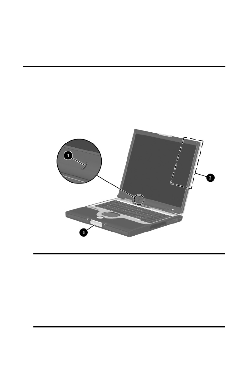
Display Components
Microphone Inputs single-channel sound.
1
MultiPort Supports an optional USB-enabled
2
Display release latch Opens the notebook.
3
Hardware Guide 1–1
wireless device such as a Bluetooth
MultiPort, 802.11b Wireless LAN
MultiPort, and future wireless
technologies.
Page 9
Identifying External Hardware
Pointing Device Components
TouchPad Models
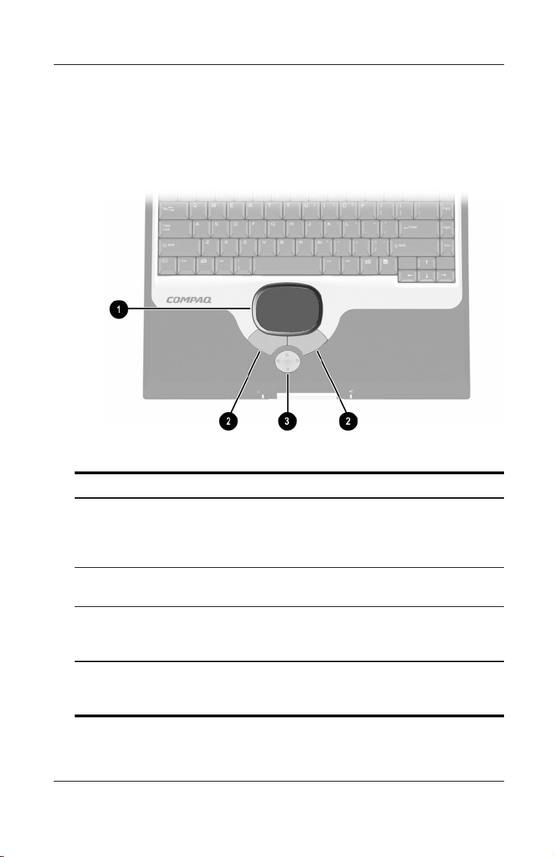
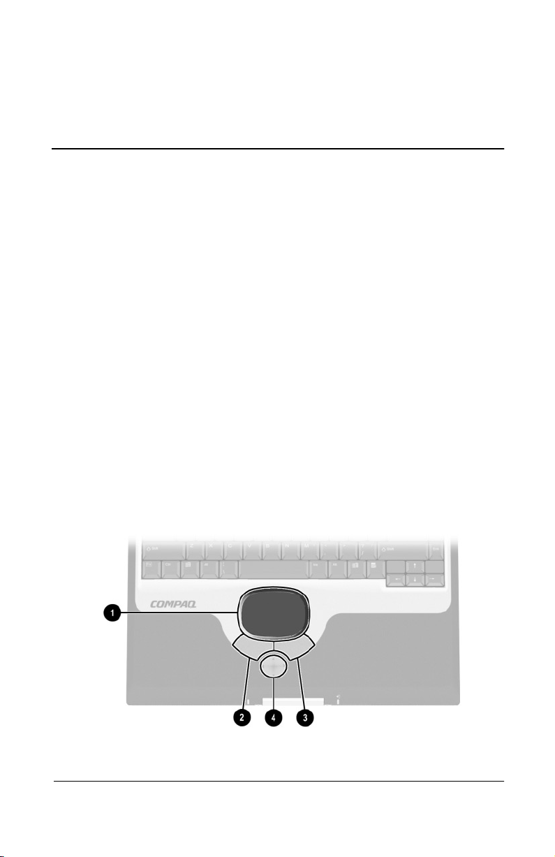
Pointing Device Components: TouchPad Models
TouchPad Moves the cursor. Can be set to
1
Left and right TouchPad
2
buttons
Scroll button Scrolls up, down, left, or right through
3
*For information about modifying pointing device functions, refer in this
guide to the “Pointing Devices and Keyboard” section, “Setting Pointing
Device Preferences.”
1–2 Hardware Guide
perform additional mouse functions
such as scroll, select, and
double-click.*
Function like the left and right buttons
on an external mouse.
most application and Internet browser
windows.
Page 10
Identifying External Hardware
Dual Device Models
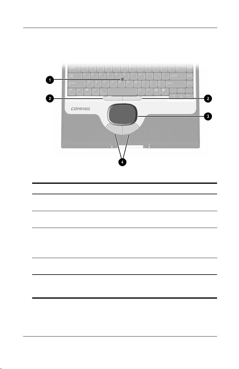
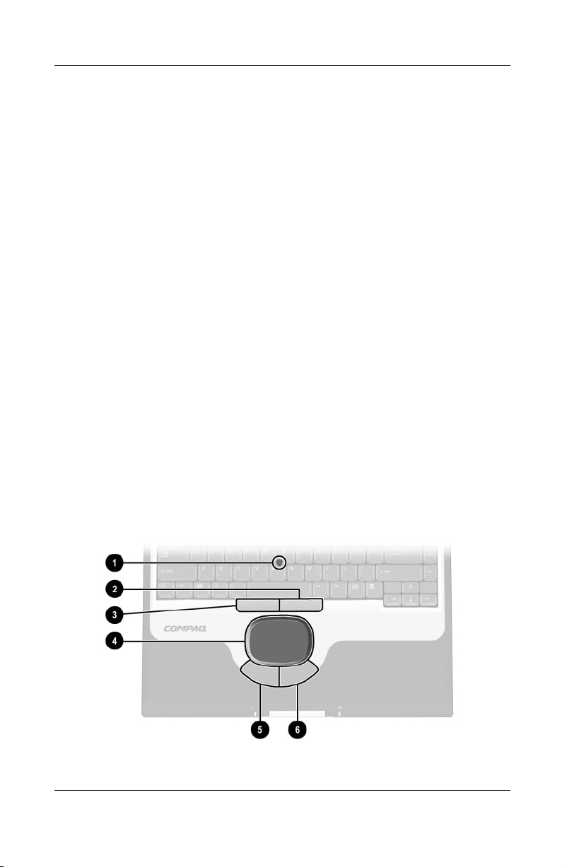
Pointing Device Components: Dual Device Models
Pointing stick Moves the cursor and selects and
1
Left and right pointing-stick
2
buttons
TouchPad Moves the pointer. Can be set to
3
Left and right TouchPad
4
buttons
*For information about modifying pointing device functions, refer in this
guide to the “Pointing Devices and Keyboard” section, “Setting Pointing
Device Preferences.”
Hardware Guide 1–3
activates items on the screen.
Function like the left and right buttons
on an external mouse.
perform additional mouse functions
such as scroll, select, and
double-click.*
Function like the left and right buttons
on an external mouse.
Page 11
Identifying External Hardware
Top Components
Power Lights
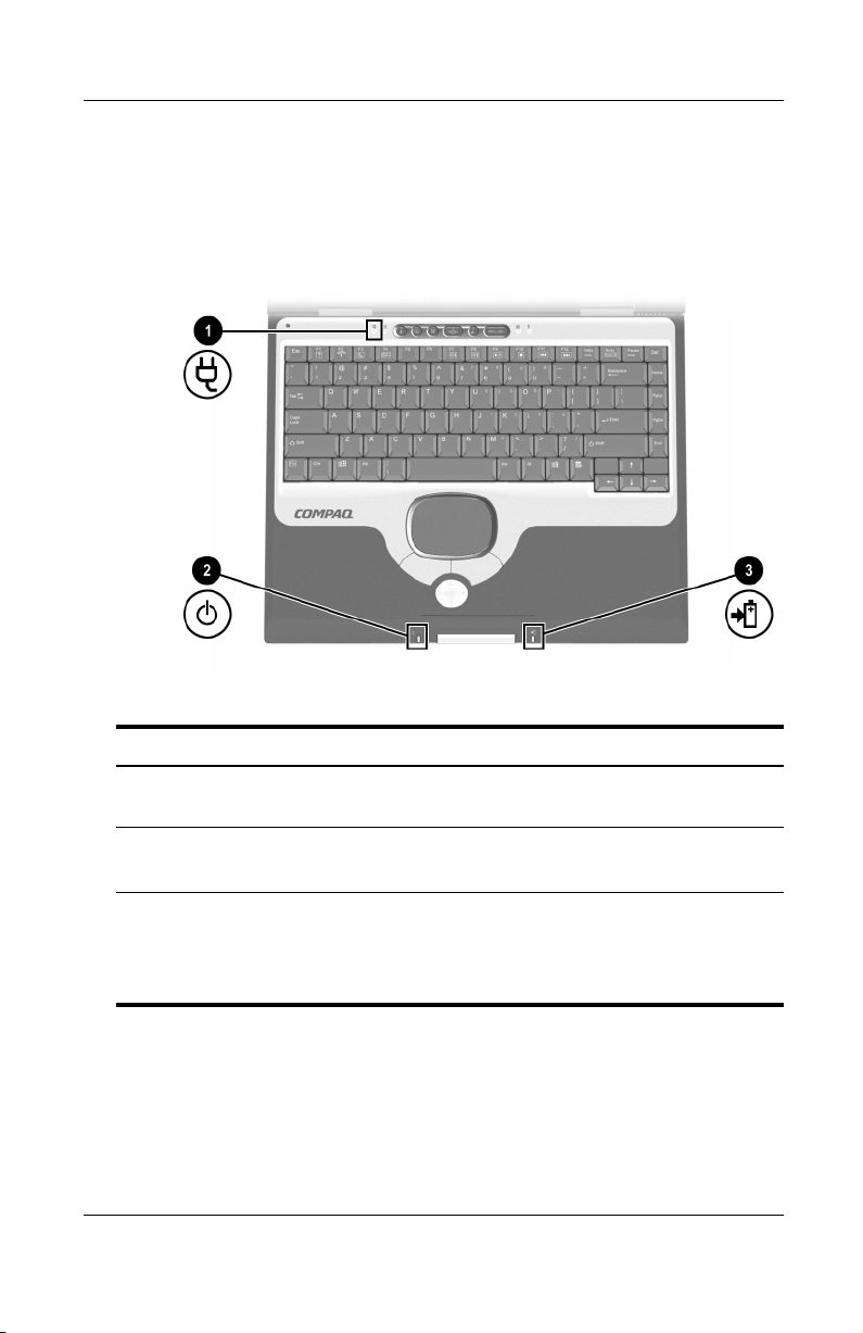
Top Components: Power Lights
AC Adapter light On: AC power is being supplied
1
Power/standby light On: Power is turned on.
2
Battery light On: A battery pack is charging.
3
1–4 Hardware Guide
through the AC Adapter.
Blinking: Notebook is in Standby.
Blinking: A battery pack that is the
only available power source has
reached a low-battery condition.
Page 12
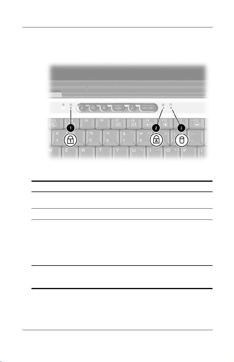
Keyboard and Drive Lights
Top Components: Keyboard and Drive Lights
Identifying External Hardware
Num lock light On: Num lock is on or the internal
1
Caps lock light On: Caps lock is on.
2
IDE (Integrated Drive
3
Electronics) drive light
*For more information about using num lock, the internal keypad, or an
external keypad, refer in this guide to the “Pointing Devices and Keyboard”
section, “Keypads.”
Hardware Guide 1–5
keypad is on.*
On: One of the following drives is
being accessed:
■
Hard drive in the hard drive bay.
■
Optional hard drive, Zip drive,
SuperDisk drive, or any type of
CD or DVD drive in the MultiBay.
Page 13
Identifying External Hardware
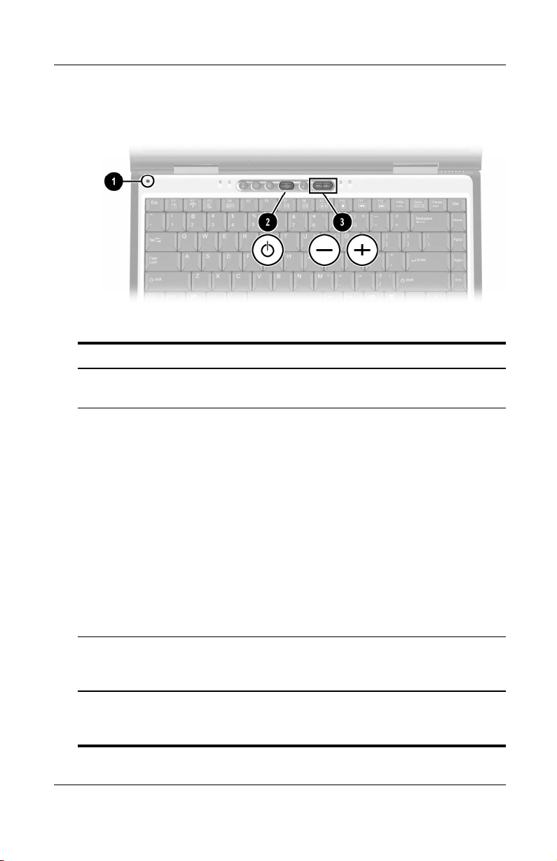
Power and Volume Controls
Top Components: Power and Volume Controls
Display switch* Turns off the notebook display if the
1
Power button* When the notebook is:
2
notebook is closed while it is on.
■
Off, briefly press to turn on the
notebook.
■
On, briefly press to initiate
Hibernation.
■
In Standby, briefly press to exit
Standby.
■
In Hibernation, briefly press to exit
Hibernation.
If the system has stopped responding
and Windows shut down procedures
cannot be used, press and hold for 4
seconds to turn off the notebook.
Volume buttons (2) Adjust, mute, or restore system volume.
3
*This table describes default settings. For information about changing the
function of the power button, display switch, or
CD to the
1–6 Hardware Guide
Software Guide,
“Power” section.
To mute or restore volume, press both
volume buttons at the same time.
hotkeys, refer on this
Fn+F3
Page 14
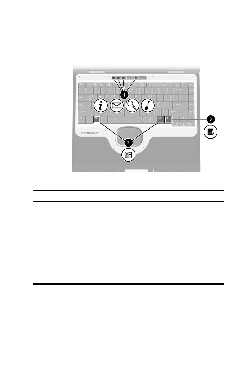
Identifying External Hardware
Easy Access Buttons and Keyboard Keys
Top Components: Easy Access Buttons and Keyboard Keys
Easy Access Buttons (4) Provide quick access to Internet or
1
Microsoft logo keys (2) Display Windows Start menu.
2
Applications key Displays shortcut menu for item
3
Hardware Guide 1–7
network destinations, or to software
applications or data files on a drive.
The icon on each button represents
the default destination. Buttons can
be programmed to different
destinations.
beneath the pointer.
Page 15
Identifying External Hardware
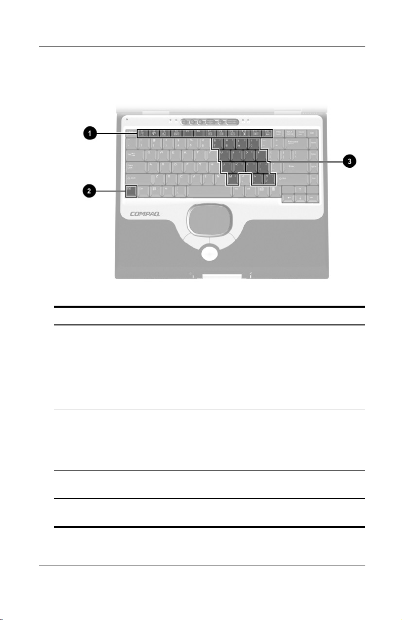
Function and Keypad Keys
Top Components: Function and Keypad Keys
Function keys (12) Perform system and application
1
2
key Combines with other keys to perform
Fn
tasks. For example, in Windows and
many applications, pressing
a Help file. When combined with the
key, the function keys F2through
Fn
and F7 through
F4
additional tasks as hotkeys.*
system tasks. For example, pressing
the
Fn+F7
brightness and pressing the
hotkeys increases screen brightness.
opens
F1
perform
F12
hotkeys decreases screen
Fn+F8
Keypad keys (15)* Can be used like the keys on an
3
*For more information about using hotkeys or keypad keys, refer in this
guide to the “Pointing Devices and Keyboard” section.
1–8 Hardware Guide
external numeric keypad.
Page 16
Front Panel Components
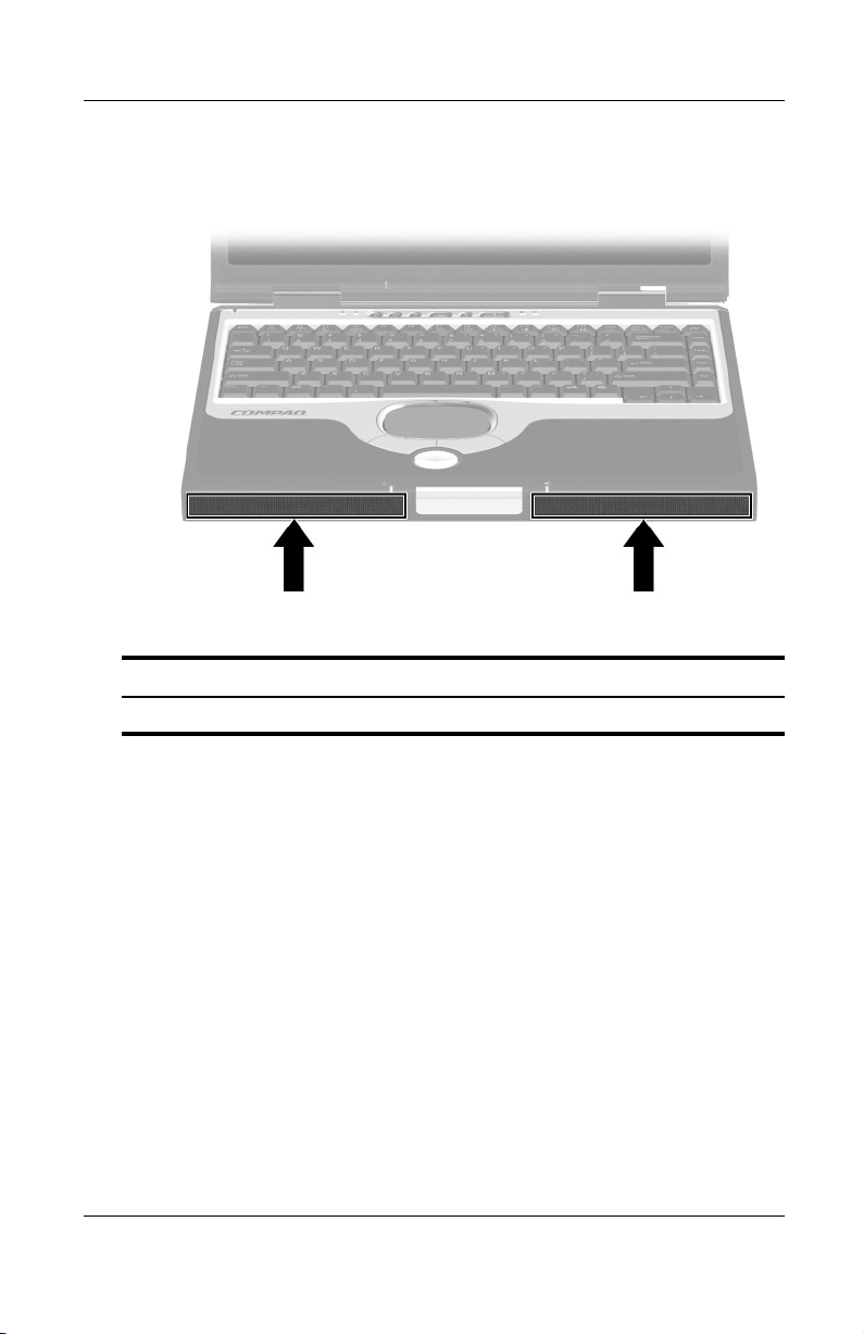
Front Panel Components
Stereo speakers (2) Produce stereo sound.
Identifying External Hardware
Hardware Guide 1–9
Page 17
Identifying External Hardware
Rear Panel Components
Connectors
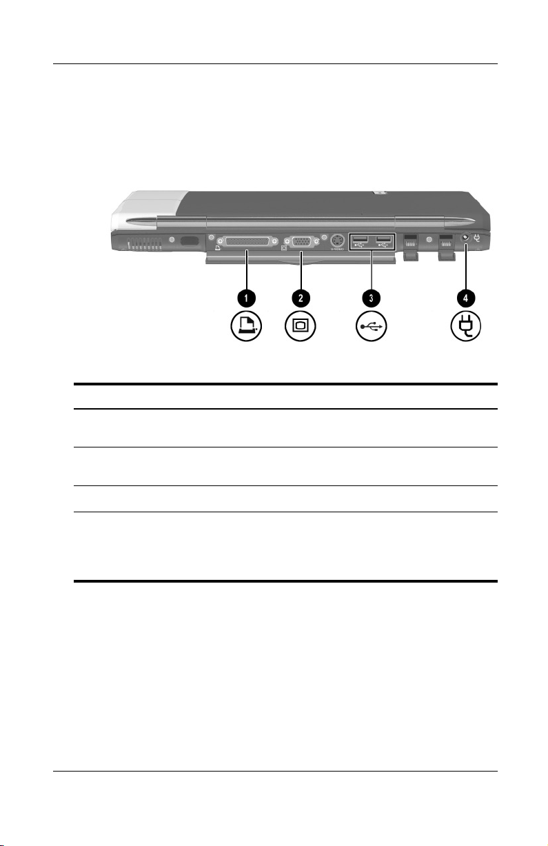
Rear Panel Components: Connectors
Parallel connector Connects an optional parallel device
1
such as a printer.
External monitor connector Connects an optional external
2
USB connectors (2) Connect optional USB devices.
3
DC power connector Connects an AC Adapter or an
4
1–10 Hardware Guide
monitor or overhead projector.
optional DC Cable, Aircraft Power
Adapter, or Automobile Power
Adapter/Charger.
Page 18
Vent, Port and Jacks
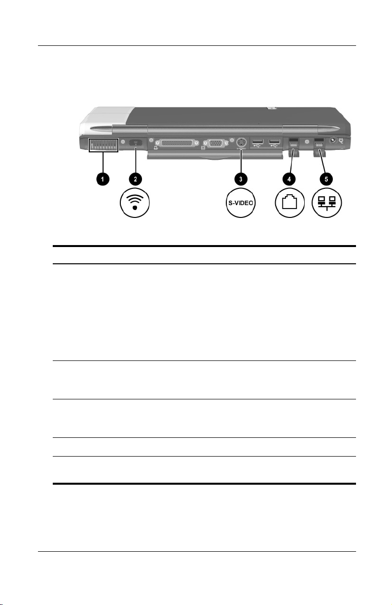
Rear Panel Components: Vent, Port and Jacks
Vent (1 of 3) Allows airflow to cool internal
1
components.
To prevent overheating, do
Ä
not obstruct the vent. Do not
allow a hard surface, such as
an adjoining optional printer,
or a fabric, such as bedding
or clothing, to block airflow.
Identifying External Hardware
Infrared port Provides wireless communication
2
S-video-out jack Connects an optional S-video device
3
RJ-11 telephone jack Connects the modem cable.
4
RJ-45 network jack Connects a network cable. A network
5
Hardware Guide 1–11
between the notebook and an
optional IrDA-compliant device.
such as a television, VCR, or
camcorder.
cable is included with select models.
Page 19
Identifying External Hardware
Left Side Components
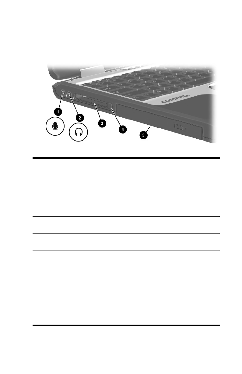
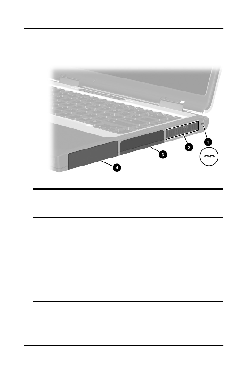
Left Side Components
Microphone jack Connects an optional single-sound channel
1
Audio-out jack Connects optional headphones, a headset,
2
PC Card slot Supports an optional Type I or Type II 32-bit
3
microphone.
or powered stereo speakers. Also connects
the audio function of an audio/video device
such as a television or VCR.
(CardBus) or 16-bit PC Card.
PC Card eject button Ejects an optional PC Card from the
4
MultiBay Supports an optional MultiBay device such
5
1–12 Hardware Guide
PC Card slot.
as a drive or a battery pack.
■
If a MultiBay drive is included with your
notebook, the drive may ship inside the
MultiBay.
■
If your notebook did not ship with a
drive inside the MultiBay, the MultiBay
contains a weight saver. The weight
saver protects the MultiBay and
reduces notebook weight.
Page 20
Right Side Components
Right Side Components
Identifying External Hardware
Security cable slot Attaches an optional security cable to
1
Vent (1 of 3) Allows airflow to cool internal
2
Hard drive bay Holds the primary hard drive.
3
Battery bay Holds the primary battery pack.
4
Hardware Guide 1–13
the notebook.
components.
To prevent overheating, do
Ä
not obstruct the vent. Do not
allow a hard surface, such as
an adjoining optional printer,
or a fabric, such as bedding
or clothing, to block airflow.
Page 21
Identifying External Hardware
Underside Components
Memory and Mini PCI Compartments
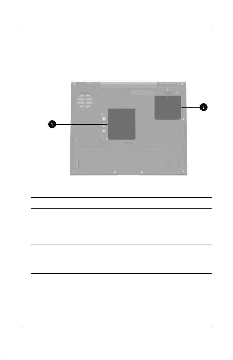
Underside Components: Memory and Mini PCI Compartments
Memory compartment Contains 2 memory slots for
1
Mini PCI (peripheral
2
component interconnect)
compartment
1–14 Hardware Guide
PC21000-compliant memory boards.
As shipped, the memory
compartment may contain 1 or 2
memory boards.
Supports an optional mini PCI board
such as a modem board. (A modem
board is included with some notebook
models.)
Page 22
Bay Components
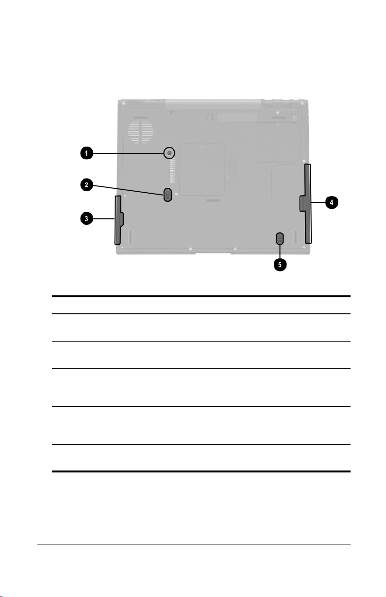
Underside Components: Bay Components
Identifying External Hardware
Hard drive bay retaining
1
screw
Battery release latch Releases the primary battery pack
2
Battery bay recess Provides a grip area for removing
3
MultiBay recess Provides a grip area for removing an
4
MultiBay release latch Releases an optional MultiBay device
5
Hardware Guide 1–15
Secures the primary hard drive in the
hard drive bay.
from the battery bay.
a primary battery pack from the
battery bay.
optional MultiBay device from the
MultiBay.
from the MultiBay.
Page 23
Identifying External Hardware
Vent and Docking Components
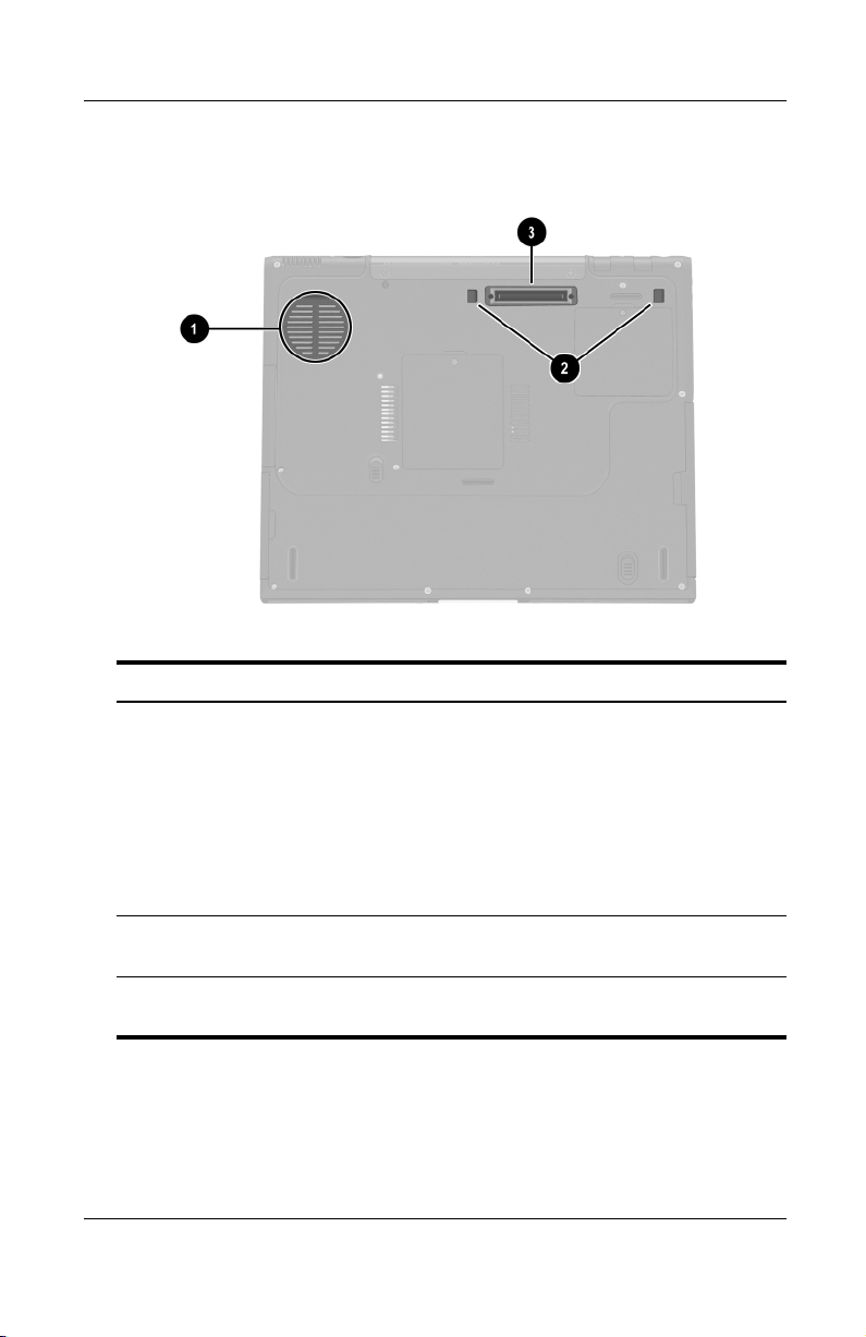
Underside Components: Vent and Docking Components
Vent (1 of 3) Provides airflow to cool internal
1
Docking latch recesses (2) Help secure the notebook to a port
2
Docking connector Connects the notebook to an optional
3
1–16 Hardware Guide
components.
To prevent overheating, do
Ä
not obstruct the vent. Using
the notebook on a soft
surface, such as a pillow,
blanket, rug, or thick clothing,
may block airflow.
replicator.
port replicator.
Page 24
Labels
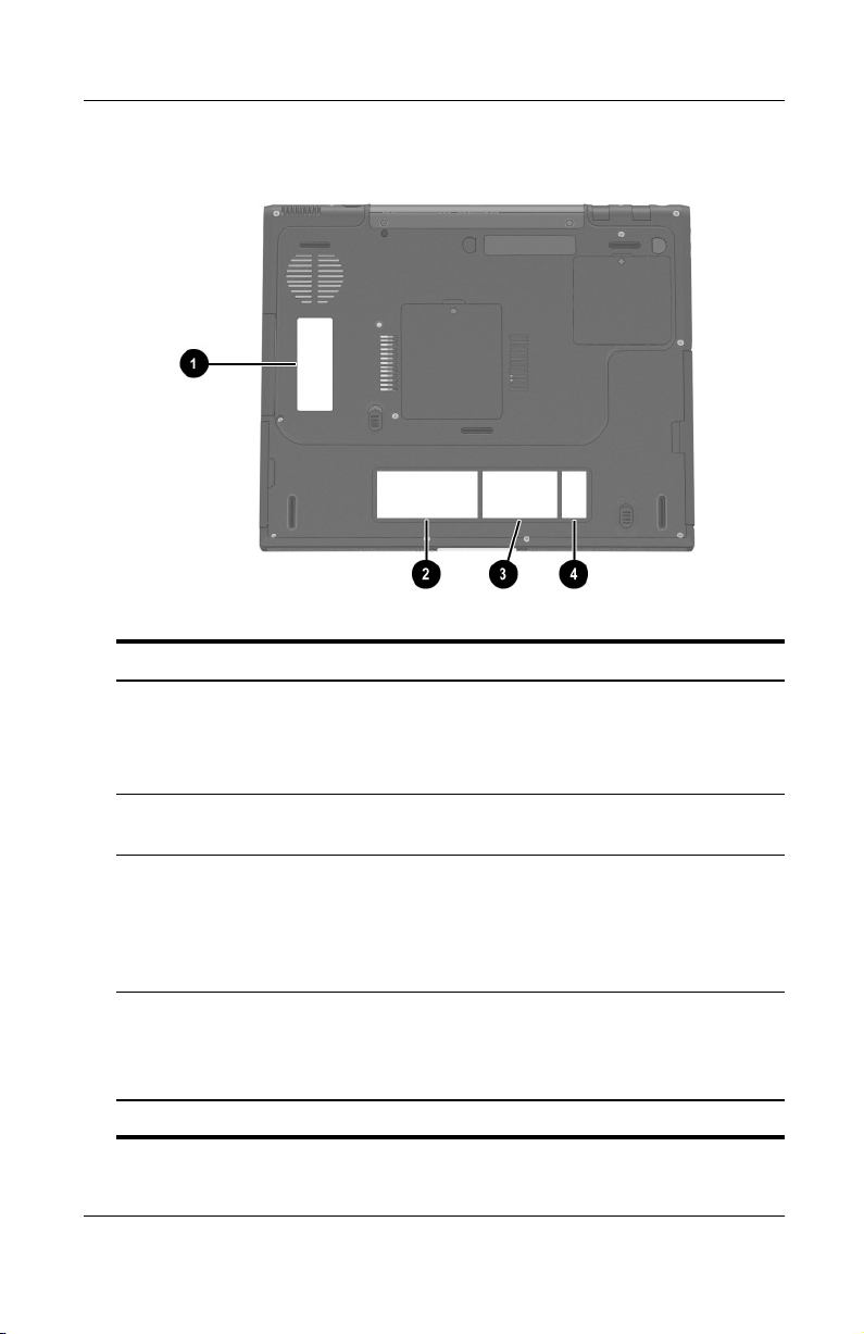
Underside Components: Labels
Identifying External Hardware
Microsoft Certificate of
1
Authenticity label*
System label* Provides regulatory information about
2
MultiPort agency approvals
3
label* (models that ship with
a wireless device only)
Serial number* Identifies the notebook. You will need
4
*The appearance and position of labels varies by model.
Hardware Guide 1–17
Contains your Product Key number.
You may need this information to
update or troubleshoot the operating
system.
the notebook.
Lists the countries in which the
wireless device has been approved
for use.
You may need this information to use
the wireless device while traveling.
this number if you call Compaq
customer support or download
software from the Compaq Web site.
Page 25
Identifying External Hardware
Additional Standard Components
The components included with the notebook vary by
geographical region and the notebook hardware ordered. The
following illustrations and tables identify the standard external
components included with most notebook models.
These illustrations do not include printed documentation,
✎
supplementary software, or drives. The primary hard drive ships
inside the hard drive bay. An optional MultiBay drive may ship
inside the MultiBay.
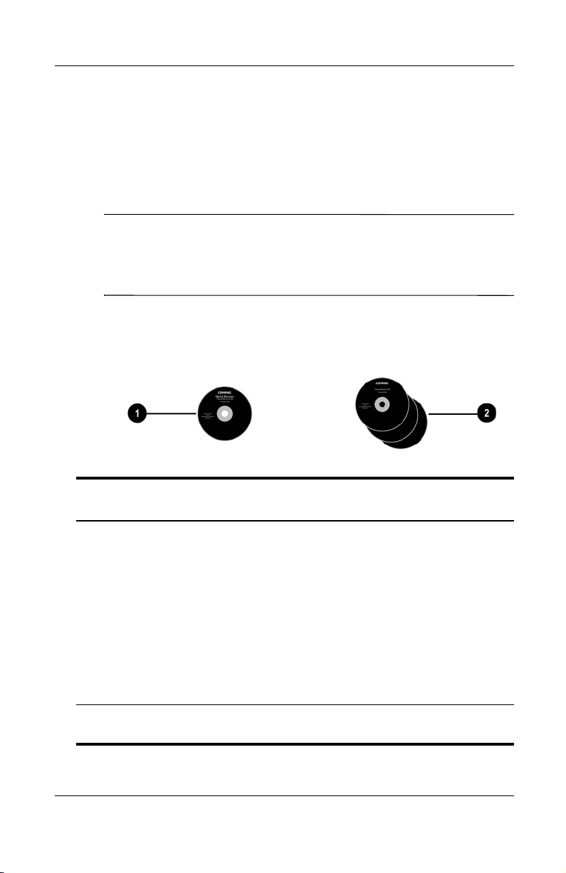
Documentation and Restore CDs
Additional Standard Components: Documentation and
Restore CDs
Documentation Library
1
Restore CDs Contain the software preinstalled on
2
1–18 Hardware Guide
CD Includes the following guides:
■
Hardware Guide
■
Software Guide
■
Modem and Networking
■
Modem Command Guidelines
(Advanced Users Only)
■
Maintenance, Shipping and
Tr av e l
■
Troubleshooting
■
Regulatory and Safety Notices
the notebook.
Page 26
Identifying External Hardware
Cord and Cables
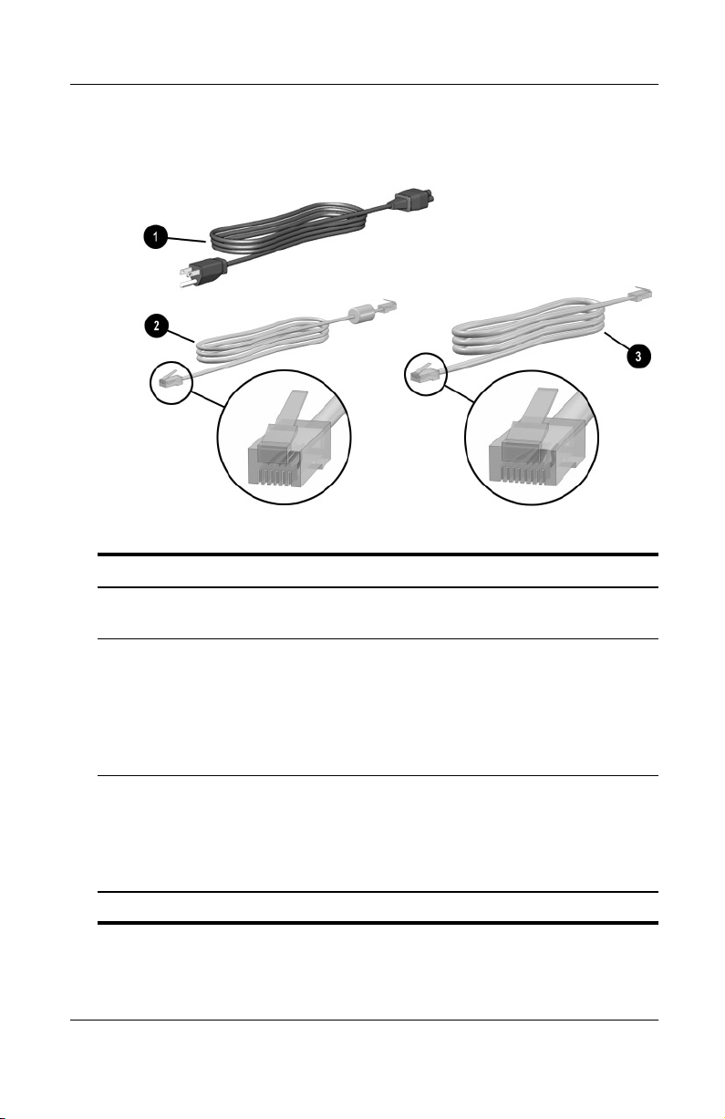
Additional Standard Components: Cord and Cables
Power cord* Connects the AC Adapter to an
1
Modem cable Connects the modem to an RJ-11
2
Network cable (select
3
models only)
*Power cords vary in appearance by region.
Hardware Guide 1–19
AC electrical outlet.
telephone jack or to a country-specific
modem adapter.
The modem cable has a
✎
6-pin
RJ-11 telephone
connector at each end.
Connects the notebook to an
Ethernet network jack.
The network cable has an
✎
8-pin
RJ-45 network
connector at each end.
Page 27
Identifying External Hardware
Adapters and Accessories
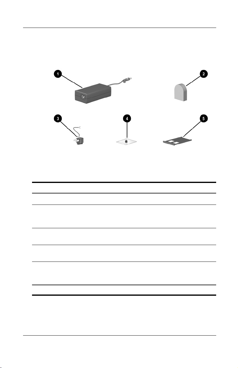
Additional Standard Components: Adapters and Accessories
AC Adapter* Converts AC power to DC power.
1
Country-specific modem
2
adapter (included by region
as required)
Japan-specific outlet
3
adapter (Japan only)
Spare pointing stick cap
4
(dual device models only)
Weight saver (may ship in
5
MultiBay)
*AC Adapters vary in appearance by region.
1–20 Hardware Guide
Adapts the modem cable to a
non-RJ-11 telephone jack.
Connects the AC Adapter to a
2-prong electrical outlet.
Replaces a worn pointing stick cap.
Can replace an optional MultiBay
device to protect the MultiBay and
reduce notebook weight
Page 28
Pointing Devices and Keyboard
Pointing Devices
Pointing Devices on TouchPad Models Only
To move the cursor, sometimes called the pointer, slide your
finger across the TouchPad surface
move the cursor. If the cursor continues to move after you release
the TouchPad, wait a few seconds and the cursor will stop
moving.
in the direction you want to
1
2
Use the left
left and right buttons on an external mouse.
Use the arrows on the scroll button
the scroll bars on the edges of windows. The scroll button moves
the viewing area up, down, right, and left in Internet browser
windows as well as most application windows.
Identifying TouchPad components
Hardware Guide 2–1
and right 3 TouchPad buttons as you would the
2
as you would the arrows on
4
Page 29
Pointing Devices and Keyboard
Pointing Devices on Dual Device Models Only
The notebook is set at the factory to enable you to use the
pointing stick and TouchPad components interchangeably. For
information about disabling some or all dual device components,
refer to “Enabling or Disabling Dual Device Components,” next
in this section.
Using the Pointing Stick Components
To move the cursor, sometimes called the pointer, press the
pointing stick
increase or decrease cursor speed, increase or decrease the
directional (not downward) pressure on the pointing stick.
cursor continues to move after you release the pointing stick, wait
a few seconds and the cursor will stop moving.
Use the right 2 and left 3 pointing-stick buttons as you would
the right and left buttons on an external mouse.
Using the TouchPad Components
To move the cursor, slide your finger across the TouchPad
surface
4
in the direction you want to move the cursor. To
1
in the direction you want to move the cursor.
If the
Use the left
left and right buttons on an external mouse.
Identifying dual device components
2–2 Hardware Guide
and right 6 TouchPad buttons as you would the
5
Page 30

Pointing Devices and Keyboard
Enabling or Disabling Dual Device Components
All dual device components are set at the factory to work
interchangeably. For example, you can move the cursor with
either the pointing-stick or the TouchPad.
You can set the notebook to respond to some, none, or all dual
device components through the operating system.
To enable or disable dual device components:
1. Access the Mouse Properties window:
❏
In Windows 2000 Professional, select Start > Settings >
Control Panel > Mouse icon.
❏
In Windows XP Home or Windows XP Professional,
select Start > Control Panel > Printers and Other
Hardware > Mouse icon.
2. Select the Advanced Features tab.
3. In the Devices list, select the device you want to enable or
disable. Then:
❏
To enable the device, select the Enable button.
❏
To disable the device, select the Disable button.
4. Select the OK button.
Hardware Guide 2–3
Page 31

Pointing Devices and Keyboard
Setting Pointing Device Preferences
The TouchPad and the dual pointing device are supported by the
mouse software in the operating system. To access the custom
mouse settings available through the operating system:
■
In Windows 2000 Professional, select Start > Settings >
Control Panel > Mouse.
■
In Windows XP Home or Windows XP Professional, select
Start > Control Panel > Printers and Other Hardware >
Mouse icon.
Among the settings you can select are:
■
TouchPad tapping, which enables you to tap the TouchPad
once to select an object or twice to double-click an object.
■
Edge motion, which enables you to continue to scroll even
though your finger has reached the edge of the TouchPad.
■
Palm Check, which helps prevent moving the cursor
unintentionally if your palms contact the TouchPad as
you type.
Other features, such as mouse trails and mouse speed preferences,
are available. To discover them, look through the tabs in the
Mouse Properties window. To learn more about a feature, select
the question mark in the upper right corner of the window, then
select the feature. To select a setting, follow the instructions on
the screen, then select the OK button.
2–4 Hardware Guide
Page 32

Hotkeys
Identifying Hotkeys
Hotkeys are preset combinations of the Fnkey1 and one of the
function keys
through
F7
notebook.
. The icons on the function keys
2
represent the hotkey functions available on your
F12
Pointing Devices and Keyboard
through F4 and
F2
Identifying hotkeys
Hardware Guide 2–5
Page 33

Pointing Devices and Keyboard
Hotkey Quick Reference
The following table identifies the hotkey functions set at
the factory. For information about changing the functions of the
or
Fn+F2
section.
Default Function Hotkey
hotkeys, refer to “Hotkey Commands,” later in this
Fn+F3
Turn a device in the MultiPort on or off.
Initiate Standby.
Switch display and image.
Decrease screen brightness.
Increase screen brightness.
Play or pause an audio CD.
Stop an audio CD.
Play the previous track on an audio CD.
Play the next track on an audio CD.
Hotkey Procedures
To use a hotkey command on the notebook keyboard:
■
Briefly press the Fn key, then briefly press the second key of
the command.
or
■
Press and hold down the Fn key, briefly press the second key
of the command, then release both keys simultaneously.
Fn+F2
Fn+F3
Fn+F4
Fn+F7
Fn+F8
Fn+F9
Fn+F10
Fn+F11
Fn+F12
To use hotkeys on an external keyboard, press the
scroll lock
key
twice, then the second key only of the hotkey combination. For
example, to use the
press
scroll lock+scroll lock+F8.
2–6 Hardware Guide
hotkeys to increase screen brightness,
Fn+F8
Page 34

Pointing Devices and Keyboard
Hotkey Commands
Turn a MultiPort Device On or Off (Fn+F2)
The
hotkeys are set at the factory to turn a device in the
Fn+F2
MultiPort on or off.
When a device in the MultiPort is off, press the
Fn+F2
hotkeys to
turn the device on. When a device in the MultiPort is on, press the
hotkeys to turn the device off.
Fn+F2
■
To send or receive messages, turn the device on.
■
To conserve power, turn the device off.
The status light on the MultiPort device is on when power is on
and off when power is off.
Identifying the MultiPort status light
Hardware Guide 2–7
Page 35

Pointing Devices and Keyboard
The
hotkeys are enabled by default, but can be disabled in
Fn+F2
Computer Setup. The device in the MultiPort can be set to remain
on or off while the
hotkeys preferences are set in Computer Setup. Computer
Fn+F2
hotkeys are disabled.
Fn+F2
Setup is a non-Windows utility. For more information about using
Computer Setup, refer on this CD to the Software Guide, “Setup
and Diagnostic Utilities” section.
1. To open Computer Setup, turn on or restart the notebook,
then press
while the F10 = ROM Based Setup message is
F10
displayed in the lower left of the screen.
❏
To change the language, press
❏
To view navigation information, press
F2.
F1.
2. Use the arrow keys to select the Security menu, then press
enter.
3. Use the arrow keys to select Device Security, then press
enter.
4. Select MultiPort Fn+F2. The status of the device in the
MultiPort is displayed at the bottom of the screen.
5. To change the status of the device in the MultiPort, press the
hotkeys. (The device in the MultiPort will remain in
Fn+F2
whichever status is selected at the time that the
Fn+F2
hotkeys
are disabled.)
6. To disable the
MultiPort Fn+F2 to Disable. (To reenable the
hotkeys, set the status field beside
Fn+F2
Fn+F2
hotkeys,
set this status field to Enable.)
7. To confirm your settings, press
F10.
8. To exit Computer Setup, use the arrow keys to select an exit
option from the File menu, then follow the instructions on
the screen.
Your preference is set as you exit Computer Setup and is in effect
when the notebook restarts.
2–8 Hardware Guide
Page 36

Initiate Standby (Fn+F3)
Pointing Devices and Keyboard
The
■
hotkeys are set at the factory to initiate Standby.
Fn+F3
When the notebook is on, press the
Standby. When Standby is initiated, your work is saved in
random access memory (RAM), the screen is cleared, and
power is conserved. While the notebook is in Standby, the
power/standby light blinks.
■
To exit Standby, briefly press the power button.
The function of the
Windows, can be changed. For example, the
set to initiate Hibernation instead of Standby. For more
information about Standby, Hibernation, and changing the
function of the
Fn+F3
Guide, “Power” section.
Switch Image (Fn+F4)
The
connected to the notebook. For example, if an external monitor
is connected to the notebook, pressing
among the notebook display, the external monitor display, and a
simultaneous display on both the notebook and the external
monitor.
Most external monitors receive video information from the
notebook using the external VGA video standard. The
hotkeys also switch images among devices receiving video
information from the notebook in other ways. The following
5 video transmission types, with examples of devices that use
them, are supported by the
hotkeys switch the image among display devices
Fn+F4
hotkeys to initiate
Fn+F3
hotkeys, called the “sleep button” in
Fn+F3
hotkeys can be
Fn+F3
hotkeys, refer on this CD to the Software
switches the image
Fn+F4
Fn+F4
hotkeys:
Fn+F4
■
LCD (notebook display)
■
External VGA (most external monitors)
■
S-video (televisions, camcorders, VCRs, and video capture
boards with S-video-in jacks)
Hardware Guide 2–9
Page 37

Pointing Devices and Keyboard
■
Composite video (televisions, camcorders, VCRs, and video
capture boards with composite-video-in jacks)
■
DVI-D (external monitors that support the DVI-D interface)
Decrease Brightness (Fn+F7)
Press the
hotkeys to decrease the brightness of the
Fn+F7
notebook screen. Decreasing brightness conserves power.
Increase Brightness (Fn+F8)
Press the
screen.
hotkeys to increase the brightness of the notebook
Fn+F8
Play, Pause or Resume an Audio CD (Fn+F9)
If an audio CD is inserted into the CD drive, press the
hotkeys to play the CD.
If an audio CD is playing in the CD drive, press the
to pause the CD.
If you have paused an audio CD in the CD drive by pressing the
hotkeys, press the
Fn+F9
hotkeys again to resume the play.
Fn+F9
Stop an Audio CD (Fn+F10)
If an audio CD is playing in the CD drive, press the
hotkeys to stop the CD.
Play Previous Track of an Audio CD (Fn+F11)
Press the
an audio CD that is playing in the CD drive.
hotkeys to select the previously played track of
Fn+F11
Fn+F9
Fn+F9
Fn+F10
hotkeys
Play Next Track of an Audio CD (Fn+F12)
Press the
that is playing in the CD drive.
2–10 Hardware Guide
hotkeys to play the next track of an audio CD
Fn+F12
Page 38

Easy Access Buttons
The 4 Easy Access buttons enable you to access an Internet or
network destination or a software application or data file on a
drive with a keystroke.
Using the Default Settings
Until your Internet or network services are set up, all buttons
launch an Internet setup wizard.
After your Internet or network services are set up, each button
opens your default Web browser and connects you to the default
destination represented by the icon on the button.
Pointing Devices and Keyboard
Identifying the Easy Access buttons
Button Name Default Assignment
Internet Opens your default Web browser to a
1
personal Web page you can customize.*
Email Opens your default email application.
2
Search Launches a search Web page that helps
3
you find destinations on the Internet.
Digital Audio Launches Windows Media Player.
4
*The factory default Web browser is Internet Explorer.
†
The factory default mail application is Outlook Express.
Hardware Guide 2–11
†
Page 39

Pointing Devices and Keyboard
Changing the Default Email Application
The Easy Access Email button and the mail buttons in your
Internet browser launch whatever email application has been set
as the default. To change the default email application in
Internet Explorer:
■
In Windows 2000 Professional, select Start > Programs >
Internet Explorer. In the Internet Explorer window, select
Tools > Internet Options > Programs tab, then follow the
instructions on the screen.
■
In Windows XP Home or Windows XP Professional, select
Start > All Programs > Internet Explorer. In the Internet
Explorer window, select Tools > Internet Options > Programs
tab, then follow the instructions on the screen.
Learning More About Windows Media Player
The Windows Media Player application is a feature of the
operating system. Instructions for using Windows Media Player
are provided on this CD in the Software Guide, “CD and DVD
Software,” and in the Windows Media Player Help file.
To access the Help file, open the Windows Media Player window,
then select Help on the menu bar.
To open the Windows Media Player window, use any 1 of the
following methods:
■
Press the Digital Audio Easy Access button.
■
Insert a CD into the optical drive, then close the tray.
■
Select the Windows Media Player icon on the taskbar.
or
■
Select the Start button, then:
❏
In Windows 2000 Professional, select Programs >
Accessories > Entertainment > Windows Media Player.
❏
In Windows XP Home or Windows XP Professional,
select All Programs > Windows Media Player.
2–12 Hardware Guide
Page 40

Pointing Devices and Keyboard
Using Custom Assignments and Schemes
An Easy Access button can be assigned to an Internet or network
destination or to any software application or data file on a drive.
For example, an Easy Access button can be assigned to open your
Internet browser to a favorite Web page or to open an application,
such as Microsoft Word, or a document, such as an Excel
worksheet, on a notebook or network drive.
Button assignments can be grouped into schemes. When you
select a scheme, only the button assignments within that scheme
are active. Button assignments and schemes are set up, changed,
or deleted in the Easy Access buttons window.
To access the Easy Access buttons window:
■
In Windows 2000 Professional, select Start > Settings >
Control Panel > Easy Access Keyboard icon.
■
In Windows XP Home or Windows XP Professional, select
Start > Control Panel > Printers and Other Hardware > Easy
Access Buttons icon.
For more information about using button assignments and
schemes, open the Easy Access button window, then use
context-sensitive Help. To use context-sensitive Help, press the
question mark button in the upper right corner of the window,
then select an item you want to know more about. A definition,
explanation, or procedure is displayed.
Hardware Guide 2–13
Page 41

Pointing Devices and Keyboard
Keypads
The notebook has an internal numeric keypad and supports an
optional external numeric keypad or an optional external
keyboard that includes a numeric keypad.
Using the Internal Keypad
The notebook keyboard contains 15 keys that can be used like the
keys on an external keypad.
When the internal keypad is turned on, each key on the internal
keypad performs the functions indicated by the icon in the upper
right corner of the key.
The standard functions of the internal keypad keys can still be
accessed while the keypad is turned on.
Identifying the internal keypad keys
2–14 Hardware Guide
Page 42

Pointing Devices and Keyboard
Turning the Internal Keypad On and Off
When the internal keypad is off, press
Fn+num lk
1 on the
notebook to turn the internal keypad on. When the internal
keypad is on, press
Fn+num lk
on the notebook (or the num lock
key on an external keypad) to turn the internal keypad off.
The num lock light
■
The internal keypad is on,
turns on under 2 conditions:
2
or
■
An optional external keypad with num lock turned on is
connected to the system.
The internal keypad cannot be turned on while an optional
external keypad is connected to the PS/2 connector on an optional
port replicator.
Identifying the Fn and
Hardware Guide 2–15
num lk
keys and the num lock light
Page 43

Pointing Devices and Keyboard
Switching Key Functions on the Internal Keypad
You can temporarily switch the functions of keys on the
internal keypad between their standard keyboard functions and
their keypad functions by using the
combination.
■
To change the functions of a keypad key to keypad functions
while the keypad is off, press and hold the
pressing the keypad key.
■
To use the keypad keys temporarily as standard keys while
the keypad is on:
❏
Press and hold the Fn key to type in lowercase.
❏
Press and hold
Fn+shift
to type in uppercase.
key or the
Fn
Fn+shift
key while
Fn
key
When the
key is released, the keypad keys return to their
Fn
keypad functions.
Using an External Keypad
Most keys on most external keypads function differently
when num lock mode is on than when num lock mode is off.
For example:
■
When num lock mode is on, most keypad keys type numbers.
■
When num lock mode is off, most keypad keys function like
arrow, page up, or page down keys.
When num lock mode on an external keypad is turned on, the
num lock light on the notebook turns on. When num lock mode
on an external keypad is turned off, the num lock light on the
notebook turns off. The num lock light on the notebook also turns
on when the internal keypad is on.
If the external keypad is connected to the PS/2 connector on an
optional port replicator, the internal keypad cannot be turned on.
If the external keypad is connected through a connector other than
a PS/2 connector, turning off num lock on the external keypad
also turns off the internal keypad.
2–16 Hardware Guide
Page 44

Pointing Devices and Keyboard
Turning Num Lock Mode On or Off as You Work
To turn num lock on or off on an external keypad as you work,
press the
key on the external keypad (not the internal
num lk
keypad).
Turning Num Lock Mode On or Off at Startup
To set the notebook to start up with a connected external keypad
in num lock mode, set your preference in Computer Setup.
Computer Setup is a non-Windows utility. For more information
about using Computer Setup, refer on this CD to the Software
Guide, “Setup and Diagnostic Utilities” section.
1. To open Computer Setup, turn on or restart the notebook,
then press
displayed in the lower left of the screen.
❏
To change the language, press
❏
For navigation instructions, press
2. Use the arrow keys to select Advanced > Device Options,
then press
while the F10 = ROM Based Setup message is
F10
F2.
F1.
enter.
3. Select or clear the Num Lock State at Boot field.
❏
To start up an external keypad with num lock mode
turned on, select the field.
❏
To start up an external keypad with num lock mode
turned off, clear the field.
4. Press
F10.
5. To save your preference and exit Computer Setup, use the
arrow keys to select File > Save Changes and Exit, then
follow the instructions on the screen.
Your preference is set as you exit Computer Setup and is in effect
when the notebook restarts.
Hardware Guide 2–17
Page 45

Battery Packs
Running the Notebook on Battery Power
When the notebook is connected to external AC power, the
notebook runs on AC power.
When a charged battery pack is in the notebook and the notebook
is not connected to external AC power, the notebook runs on
battery power.
The notebook switches between AC power and battery power
according to the availability of an external AC power source. For
example, if the notebook contains a charged battery pack and is
running on external AC power supplied through the AC Adapter,
the notebook will switch to battery power if the AC Adapter is
disconnected from the notebook.
Whether to leave a battery pack in the notebook or in storage
depends on how you work. Keeping a battery pack in the
notebook enables the battery pack to charge whenever the
notebook is connected to external AC power and also protects
your work in case of a power outage.
3
On the other hand, a battery pack in the notebook slowly
discharges when the notebook is turned off.
If you will not be using the notebook for 2 weeks or more,
removing the battery and storing it as described in “Storing a
Battery Pack,” later in this section, will prolong its life. For more
information about leaving your work, refer on this CD to the
Software Guide, “Power” section.
Hardware Guide 3–1
Page 46

Battery Packs
Identifying Battery Packs
The notebook supports up to 2 battery packs:
■
A primary battery pack 1 is an 8-cell lithium ion battery
pack that can be used only in the battery bay. One primary
battery pack is included with the notebook.
■
A MultiBay battery pack 2 is an optional 8-cell prismatic
lithium ion battery pack that can be used only in the
MultiBay.
For information about the lights and button on a MultiBay
battery pack, refer to “Monitoring the Charge in a Battery
Pack,” later in this section.
Identifying a primary and a MultiBay battery pack
3–2 Hardware Guide
Page 47

Inserting or Removing a Primary Battery Pack
CAUTION: To prevent loss of work when removing a battery pack
Ä
that is the sole power source, initiate Hibernation or turn off the
notebook before removing the battery pack.
To insert a battery pack, slide the battery pack into the battery bay
until it is seated
To remove a battery pack, slide and hold the battery release
latch
pack from the battery bay
To exit Hibernation, briefly press the power button.
toward the rear of the notebook as you pull the battery
2
1
.
.
3
Battery Packs
Inserting or removing a primary battery pack
Hardware Guide 3–3
Page 48

Battery Packs
Inserting or Removing a MultiBay Battery Pack
CAUTION: To prevent loss of work when removing a battery pack
Ä
that is the sole power source, initiate Hibernation or turn off the
notebook before removing the battery pack.
To insert a battery pack, slide the battery pack into the MultiBay
until it is seated
To remove a battery pack, slide and hold the MultiBay release
latch
pack from the MultiBay
To exit Hibernation, briefly press the power button.
toward the front of the notebook as you pull the battery
2
1
.
.
3
Inserting or removing a MultiBay battery pack
CAUTION: To prevent damage to the MultiBay when no device is in
Ä
the MultiBay, insert the weight saver to protect the bay opening.
The weight saver can be inserted or removed while the notebook is
on, off, in Standby, or in Hibernation.
3–4 Hardware Guide
Page 49

Charging a Battery Pack
All battery packs inserted into the notebook charge whenever the
notebook is connected to external power. External power can be
supplied through an AC Adapter or an optional Automobile
Power Adapter/Charger.
An optional Aircraft Power Adapter can be used to run the
✎
notebook, but cannot be used to charge a battery pack.
Battery packs charge whether or not the notebook is in use, but
charge faster when the notebook is off. Charging may be delayed
if a battery pack is new, has not been used for 2 weeks or more, or
is much warmer or cooler than room temperature. A new primary
battery pack charges in the notebook as shipped in about 2 hours.
Other charging times will vary.
While a battery pack is charging, the battery light on the notebook
is on. The light turns off when all battery packs in the system are
fully charged.
Battery Packs
Identifying the battery light
Hardware Guide 3–5
Page 50

Battery Packs
Charging a New Battery Pack
Fully charge the battery pack while the notebook is connected to
AC power through the AC Adapter.
A new battery pack that has been partially charged, but not fully
charged, can run the notebook, but battery charge displays may
be inaccurate.
Charging an In-Use Battery Pack
To prolong battery life and increase the accuracy of battery
charge displays:
■
Allow a battery pack to discharge to 10 percent of a full
charge through normal use before charging it.
■
When you charge a battery pack, charge it fully.
Charging a Primary and a MultiBay Battery Pack
If a primary battery pack is inserted into the battery bay and a
MultiBay battery pack is inserted into the MultiBay, the primary
battery pack is the first to charge and the MultiBay battery pack is
the first to discharge.
3–6 Hardware Guide
Page 51

Battery Packs
Monitoring the Charge in a Battery Pack
Obtaining Accurate Charge Information
To increase the accuracy of all battery charge displays:
■
Allow a battery pack to discharge to about 10 percent of a full
charge through normal use before charging it.
■
When you charge a battery pack, charge it fully.
■
If a battery pack has not been used for 1 month or more,
calibrate the battery pack instead of simply charging it. For
calibration instructions, refer to “Calibrating a Battery Pack,”
later in this section.
Displaying Charge Information on the Screen
Accessing Charge Displays
To access information about the status of any battery pack in the
notebook:
■
Select the Power Meter icon on the taskbar,
or
■
Access the Power Meter tab. To access the Power Meter tab:
❏
In Windows 2000 Professional, select Start > Settings >
Control Panel > Power Options icon > Power Meter tab.
❏
In Windows XP Home or Windows XP Professional,
select Start > Control Panel > Performance and
Maintenance > Power Options icon > Power Meter tab.
Hardware Guide 3–7
Page 52

Battery Packs
Interpreting Charge Displays
Most charge displays report battery status in both percent
and time.
■
The percent indicates the amount of charge remaining in the
battery pack.
■
The time indicates the approximate running time remaining
on the battery pack if the battery pack continues to provide
power at the current level. For example, the time remaining
will decrease if you start playing a DVD and will increase if
you stop playing a DVD.
Most charge displays identify battery packs by location.
■
Location 1 is the battery bay.
■
Location 2 is the MultiBay.
In some displays, a lightening bolt icon may be displayed beside
a battery pack location. The icon indicates that the battery pack in
that location is charging.
3–8 Hardware Guide
Page 53

Battery Packs
Displaying Charge Information on a Battery Pack
You can determine the percent of a full charge remaining in a
battery pack that is not inserted into the notebook by using the
battery Quick Check feature. MultiBay battery packs have battery
Quick Check. Primary battery packs do not.
To display the percent of a full charge remaining in a MultiBay
battery pack, press the Quick Check button
on the battery pack.
1
The Quick Check lights
on the battery pack indicate the charge
2
remaining in the battery pack as shown in the following table.
Indication Percent of a Full Charge Remaining
4 lights on 76 to 100%
3 lights on 51 to 75%
2 lights on 26 to 50%
1 light on 11 to 25%
1 light blinking 0 to 10%
Identifying the button and lights on a MultiBay battery pack
Hardware Guide 3–9
Page 54

Battery Packs
Managing Low-Battery Conditions
Some low-battery condition alerts and system responses can be
changed in the Power Options window of the operating system.
The information in this section describes the alerts and system
responses set at the factory. Preferences set in the Power Options
window do not affect lights.
Identifying Low-Battery Conditions
Low-Battery Condition
When a battery pack that is the sole power source available to the
notebook reaches a low-battery condition (10 percent of a full
charge), the battery light blinks.
Critical Low-Battery Condition
If a low-battery condition is not resolved, the notebook enters a
critical low-battery condition (1 percent of a full charge).
In a critical low-battery condition:
■
If Hibernation is enabled and the notebook is on or in
Standby, the notebook initiates Hibernation.
■
If Hibernation is disabled and the notebook is on or in
Standby, the notebook remains briefly in Standby, then shuts
down and loses your unsaved work.
Hibernation is enabled at the factory. To verify that Hibernation
has not been disabled, be sure that the Enable Hibernate Support
check box on the Hibernate tab is selected. To access the tab:
■
In Windows 2000 Professional, select Start > Settings >
Control Panel. Double-click Power Options.
■
In Windows XP Home or Windows XP Professional, select
Start > Control Panel > Performance and Maintenance >
Power Options icon.
3–10 Hardware Guide
Page 55

Resolving Low-Battery Conditions
CAUTION: If the notebook has reached a critical low-battery
Ä
condition (1 percent of a full charge) and has initiated Hibernation,
do not restore power until Hibernation is complete. Hibernation is
complete when the power/standby light turns off.
When External Power Is Available
Select 1 of the following options:
■
Connect the AC Adapter.
■
Plug an optional Automobile Power Adapter/Charger into the
notebook and into a vehicle cigarette lighter receptacle.
■
Plug an optional Aircraft Power Adapter into the notebook
and into the in-seat power supply available on some
commercial aircraft. (An optional Aircraft Power Adapter
can run the notebook but cannot charge a battery pack.)
When a Charged Battery Pack Is Available
Battery Packs
Turn off the notebook or initiate Hibernation, insert a charged
battery pack while the notebook is off or in Hibernation, then turn
on the notebook.
When No Power Source Is Available
Initiate Hibernation. Or, save your work, then shut down the
notebook.
When the Notebook Cannot Exit Hibernation
If the notebook lacks the power to exit Hibernation:
1. Insert a charged battery pack or connect external power.
2. To exit Hibernation, briefly press the power button.
Hardware Guide 3–11
Page 56

Battery Packs
Calibrating a Battery Pack
When to Calibrate
Calibrate an in-use primary or MultiBay battery pack whenever
battery status displays seem inaccurate or whenever the battery
pack has not been used for 1 month or more. It should not be
necessary to calibrate any battery pack, even if it is heavily used,
more than once a month. It is not necessary to calibrate a new
battery pack before first use.
How to Calibrate
Calibration requires 3 steps:
1. Fully charge the battery pack.
2. Fully discharge the battery pack.
3. Fully recharge the battery pack.
Charging the Battery Pack
You can charge the battery pack while the notebook is in use
or off, but the battery pack will charge faster while the notebook
is off.
To charge the battery pack:
1. Insert the battery pack into the notebook.
2. Connect the notebook to an AC outlet or an optional
Automobile Power Adapter/Charger. (The battery light
turns on.)
3. Leave the notebook connected to AC power until the battery
pack is fully charged. (The battery light turns off.)
3–12 Hardware Guide
Page 57

Discharging the Battery Pack
The notebook must remain on while the battery pack is being
discharged. The battery pack can discharge whether or not you
are using the notebook, but will discharge faster while the
notebook is in use.
■
If you plan to leave the notebook untended during the
discharge, save your work before beginning the discharge
procedure.
■
If you use the notebook occasionally during the discharge
procedure and have set energy-saving timeouts, expect the
following performance from your system during the
discharge process:
❏
The monitor will not turn off automatically.
❏
Hard drive speed will not decrease automatically while
the notebook is idle.
❏
System-initiated Standby will not occur.
❏
System-initiated Hibernation will not occur until the
battery has discharged to a critical low-battery condition.
Battery Packs
To fully discharge a battery pack:
1. When the battery light turns off indicating that the battery
pack is fully charged, access the Power Schemes tab:
❏
In Windows 2000 Professional, select Start > Settings >
Control Panel > Power Management icon > Power
Schemes tab.
❏
In Windows XP Home or Windows XP Professional,
select Start > Control Panel > Appearance and Themes
icon > Power Options icon > Power Schemes tab.
2. Record the 2 settings in the Plugged In column and the
2 settings in the Running on Batteries column so that you can
reset them after the calibration.
Hardware Guide 3–13
Page 58

Battery Packs
3. Use the drop-down lists to set the 4 options in both columns
to Never.
4. Select the OK button.
5. Disconnect the notebook from the AC power source, but
do not turn off the notebook.
6. Run the notebook on battery power until the battery pack is
fully discharged. (The battery light begins to blink when the
battery pack has discharged to a low-battery condition. When
the battery pack is fully discharged, the notebook initiates
Hibernation.)
Recharging the Battery Pack
1. Reconnect the notebook to external AC power and retain the
connection until the battery pack is fully recharged. (The
battery light turns off.)
You can use the notebook while the battery pack is recharging
but the battery pack will charge faster if the notebook is off.
2. If the notebook is off, turn it on when the battery pack is fully
charged and the battery light turns off.
3. Access the Power Schemes tab:
❏
In Windows 2000 Professional, select Start > Settings >
Control Panel > Power Management icon > Power
Schemes tab.
❏
In Windows XP Home or Windows XP Professional,
select Start > Control Panel > Appearance and Themes
icon > Power Options icon > Power Schemes tab.
4. Referring to the settings you recorded earlier, re-enter your
settings for the 2 options in the Plugged In column and the
2 options in the Running on Batteries column.
5. Select the OK button.
3–14 Hardware Guide
Page 59

Battery Packs
Battery Conservation Procedures and Settings
Using the battery conservation procedures and settings described
below extends the time that a battery pack can run the notebook
from a single charge.
Conserving Power as You Work
To conserve power as you use the notebook:
■
Turn off wireless and local area network (LAN) connections
and exit modem applications when you are not using them.
■
Disconnect external devices you are not using that are not
connected to an external power source.
■
Stop or remove a PC Card you are not using.
■
Remove a CD or DVD you are not using.
■
Use the
screen brightness as you need it.
Fn+F7
and
hotkeys to quickly lower and raise
Fn+F8
■
Use optional powered speakers instead of the internal
speakers, or use the volume buttons to quickly raise and
lower system volume as you need it.
■
Turn off a device connected to the S-video connector by
using the
hotkeys or by turning off support for the
Fn+F4
device in Windows.
■
Run the notebook on external power while formatting a
diskette.
■
If you leave your work, initiate Standby or Hibernation or
shut down the notebook.
Hardware Guide 3–15
Page 60

Battery Packs
Selecting Power Conservation Settings
To set the notebook to conserve power:
■
Select a short wait for the screen saver and select a screen
saver with minimal graphics and motion. To access screen
saver settings:
❏
In Windows 2000 Professional, select Start > Settings >
Control Panel > Display > Screen Saver tab.
❏
In Windows XP Home or Windows XP Professional,
select Start > Control Panel > Appearance and Themes >
Display icon > Screen Saver tab.
■
Follow the instructions on this CD in the Software Guide,
“Power” section, to:
❏
In the operating system, select a Power Scheme with low
power-use settings.
❏
In SpeedStep, select the Battery Optimized mode or
Maximum Battery Mode (Windows 2000 Professional
only).
3–16 Hardware Guide
Page 61

Storing a Battery Pack
If a notebook will be unused and unplugged for more than
2 weeks, remove and store any battery packs.
CAUTION: To prevent damage to a battery pack, do not expose it
Ä
to high temperatures for extended periods of time.
High temperatures, which may be present in parked cars or some
workplaces, accelerate the self-discharge rate of a stored battery
pack. To prolong the charge of a stored battery pack, place it in a
cool, dry place.
Use the following table to estimate how long you can safely store
a battery pack. The storage times provided are based on a battery
pack that contains 50 percent of a full charge. A fully charged
battery pack can be safely stored for longer times; a battery pack
containing a lower charge can be safely stored for less time.
Calibrate a battery pack that has been stored for 1 month or more
before using it.
Battery Packs
You Can Safely Store a Battery
At These Temperatures
Temperature
Range °F
115°–140° 46°–60° Less than 1 month
79°–113° 26°–45° No more than 3 months
32°–77° 0°–25° 1 year
Hardware Guide 3–17
Temperature
Range °C Storage Time
Pack for This Time
Page 62

Battery Packs
Disposing of a Used Battery Pack
WARNING: There is a risk of fire and chemical burn if a battery
Å
pack is handled improperly. Do not disassemble, crush, or puncture
a battery pack or short the contacts on a battery pack. Do not
expose a battery pack to temperatures higher than 60° C (140° F),
or dispose of a battery pack in water or fire.
When a battery pack has reached the end of its useful life, do not
dispose of it in general household waste.
■
In North America, you can dispose of battery packs by using
the Compaq battery recycling program. This program
provides you with a postage-paid battery pack mailer
preaddressed to a reclamation facility where the metals are
recycled. For more information, call the telephone number
listed for your location in the Worldwide Telephone Numbers
booklet, included with the computer.
■
In Europe, dispose of or recycle battery packs by using the
public collection system or by returning them to Compaq,
your authorized Compaq partners, or their agents.
■
In other regions, refer to the Worldwide Telephone Numbers
booklet, included with the notebook, to contact a Compaq
authorized dealer, reseller, or service provider and request
information about battery pack disposal.
For more information about battery pack precautions and disposal
and the complete text of governmental agency notices, refer on
this CD to the Regulatory and Safety Notices guide.
Finding More Power Information
For more information about using Standby and Hibernation,
conserving power, setting power preferences, and using other
power management features, refer on this CD to the Software
Guide, “Power” section.
3–18 Hardware Guide
Page 63

Adding a Drive to the System
Removable drives enable you to store and access data.
A standard removable drive can be added to the system by
inserting the drive into the notebook or an optional port replicator.
A USB drive can be added by connecting the drive to a USB
connector on the notebook or a port replicator. Hard drive
functions can also be added with a microdrive PC Card.
For information about connecting a USB drive, refer in this guide
to the “External Device Connections” section, “Connecting a
USB Device.” For information about PC Cards, refer to the
“Hardware Upgrades” section, “Using PC Cards.”
The notebook contains 2 drive bays:
■
The hard drive bay supports only a 9.5-mm hard drive. Any
hard drive in the hard drive bay is the primary hard drive.
4
Drives
■
The MultiBay supports a 9.5-mm hard drive (inserted into a
MultiBay hard drive adapter) and the following 12.7-mm
standard removable drives:
❏
CD-ROM drive
❏
CD-RW drive
❏
DVD-ROM drive
❏
DVD-RAM drive
❏
DVD/CD-RW drive
Hardware Guide 4–1
❏
Diskette drive
❏
SuperDisk drive
❏
Zip drive
Page 64

Drives
Understanding Drive Terms
Terms for Types of Drives
A drive that can be inserted or removed from the notebook or an
optional port replicator is a standard removable drive. A drive
that can be inserted or removed from a MultiBay is a MultiBay
drive. A drive that connects to a USB connector is a USB drive.
A hard drive is usually used for the permanent storage of data
files and software such as system files, applications, and drivers.
A hard drive is sometimes called a hard disk drive or the HDD.
Disk drives include diskette drives, SuperDisk drives, and Zip
drives. SuperDisk and Zip drives are high-capacity disk drives.
Disk drives are often used to store or transport data. The notebook
can read or write to any MultiBay disk drive. A diskette drive is
sometimes called a floppy disk drive, floppy drive, or FDD.
Optical drives include CD and DVD drives. Optical drives are
used to store or transport data and to play music and movies.
DVD drives have the higher capacity. The notebook can read or
write to optical drives as described in the following table.
Optical Drive Read Write
CD-ROM drive Yes No
CD-RW drive Yes Yes
DVD-ROM drive Yes No
DVD-RAM drive Yes Yes
DVD/CD-RW drive Yes Yes
Terms for Drive Media
A diskette, disk, or disc that can be inserted or removed from a
drive is referred to as a drive medium. In this guide a diskette is
used in a diskette drive, a disk is used in a high-capacity disk
drive, and a disc is used in an optical drive.
4–2 Hardware Guide
Page 65

Caring for Drives
Drives are fragile notebook components that must be handled
with care. The following cautions apply to all drives at all times.
Cautions that concern specific procedures are included with the
procedures provided later in this section.
CAUTION: To prevent damage to the notebook or a drive and loss
of work:
Ä
■
Do not remove the primary hard drive (the hard drive in the
hard drive bay) except for repair or replacement. For
information about replacing the primary hard drive, refer in this
guide to the “Hardware Upgrades” section, “Replacing the
Primary Hard Drive.” For information about other ways to use
more than 1 hard drive in the system, refer to “Adding a Drive to
the System,” earlier in this section.
■
Electrostatic discharge can damage electronic components. To
prevent electrostatic damage to the notebook or a drive, follow
these 2 precautions: 1) Discharge yourself from static electricity
before handling a drive by touching a grounded metal object
and 2) Avoid touching the connectors on a drive. For more
information about preventing electrostatic damage, refer on this
CD to the
■
Excessive force can damage drive connectors. When you insert
a drive, use only enough pressure to seat the drive.
■
Handle a drive carefully. Do not drop it.
■
Avoid exposing a hard drive to devices with magnetic fields.
Products with magnetic fields include video and audio tape
erasure products, monitors, and speakers. Security devices
with magnetic fields include airport walk-through devices and
security wands. The airport security devices that check carry-on
luggage, usually while it is placed on a conveyor belt, use x-rays
instead of magnetism and will not damage a hard drive.
■
Do not spray a drive with cleaners.
■
Avoid exposing a drive to liquids or temperature extremes.
■
If you mail a drive, ship it in packaging that protects it from
shock, vibration, temperature, and humidity. Label the package
“FRAGILE.”
Regulatory and Safety Notices
Drives
guide.
Hardware Guide 4–3
Page 66

Drives
Using the IDE Drive Light
The IDE (Integrated Drive Electronics) light turns on when any
type of drive except a diskette drive is being accessed.
Identifying the IDE drive light
4–4 Hardware Guide
Page 67

Drives
Removing and Inserting a MultiBay Drive
Using a MultiBay Hard Drive Adapter
A hard drive must be inserted into a MultiBay hard drive adapter
before it can be used in the MultiBay.
A hard drive assembly (a hard drive inserted into a MultiBay
adapter) is inserted into and removed from the MultiBay the same
way as any other MultiBay drive.
Inserting a Hard Drive into a MultiBay Hard Drive Adapter
1. To open the adapter, slide the switches on the left side of the
adapter toward the front and rear of the adapter.
Sliding the selection switches on the adapter
Hardware Guide 4–5
Page 68

Drives
2. Lower the drive into the adapter 1, then slide the drive
connectors on the drive toward the drive connectors in the
adapter
Inserting a hard drive into a MultiBay hard drive adapter
until the connectors engage and the drive is seated.
2
4–6 Hardware Guide
Page 69

Removing a Hard Drive from a MultiBay Hard Drive Adapter
1. Slide the adapter release latches on the front and rear of the
adapter toward the outside of the adapter.
Drives
Sliding the adapter release latches
Hardware Guide 4–7
Page 70

Drives
2. Gently disengage the drive connectors 1 by sliding the drive
toward the front of the adapter.
3. Remove the drive from the adapter
Removing a hard drive from a MultiBay hard drive adapter
2
.
Removing a Drive from the MultiBay
CAUTION: To prevent an unresponsive system and loss of work, stop
the drive before you remove it. To stop the drive:
Ä
■
In Windows 2000 Professional, select the Unplug or Eject
Hardware icon on the taskbar, then select the drive you plan to
remove. A message is displayed when it is safe to remove the
drive.
■
In Windows XP Home or Windows XP Professional, select the
Safely Remove Hardware icon on the taskbar, then select the
drive you plan to remove. A message is displayed when it is
safe to remove the drive. (To display the Safely Remove
Hardware icon, select the Show Hidden Icons icon in the
system tray.)
4–8 Hardware Guide
Page 71

Drives
1. If the drive has a media tray, remove the media, then close
the tray.
2. Stop the drive as instructed in the preceding caution.
3. Slide and hold the MultiBay release latch
front of the notebook as you pull the drive or drive assembly
(a hard drive inserted into a MultiBay hard drive adapter) out
.
of the MultiBay
When a drive or drive assembly is correctly removed from the
MultiBay, the notebook beeps 3 times.
CAUTION: To prevent damage to the MultiBay when no device is in
Ä
the MultiBay, insert the weight saver to protect the bay opening.
The weight saver can be inserted or removed while the notebook is
on, off, in Standby, or in Hibernation.
2
1
toward the
Removing a drive from the MultiBay
Hardware Guide 4–9
Page 72

Drives
Inserting a Drive into the MultiBay
1. Before inserting a hard drive into the MultiBay, insert the
drive into a MultiBay hard drive adapter as described earlier
in this section. (No other type of drive requires an adapter.)
2. With the connectors
on the drive or drive assembly (a hard
1
drive inserted into a MultiBay hard drive adapter) facing into
the MultiBay, slide the drive or drive assembly into the
.
MultiBay until it is seated
2
When a drive or drive assembly is correctly inserted into the
MultiBay, the notebook beeps 3 times.
Inserting a hard drive assembly into the MultiBay
4–10 Hardware Guide
Page 73

Inserting and Removing Drive Media
Inserting a CD or DVD
1. Be sure the notebook is on.
Drives
2. Press the media release button
the media tray, then pull the tray outward until it is fully
extended
3. Position a CD or one-sided DVD over the tray label side up.
4. Gently press the disc onto the tray spindle
snaps into place. Handle the disc by the edges, not the flat
surfaces. (If the media tray is not fully extended, tilt the disc
to position it over the tray spindle, then press it downward
into position.)
5. Close the media tray
2
.
.
4
on the drive bezel to release
1
until the disc
3
Inserting a CD or DVD into an optical drive
Hardware Guide 4–11
Page 74

Drives
Removing a CD or DVD (With Power)
If power is available:
1. Be sure the notebook is on.
2. Press the release button
on the drive bezel to release the
1
media tray, then pull the tray outward until it is fully
extended
3. Remove the disc from the tray
2
.
by gently pushing down on
3
the spindle while pulling up on the outer edges of the disc. If
the media tray is not fully extended, tilt the disc as you
remove it. Handle the disc by the edges, not the flat surfaces.
4. Close the media tray.
5. Place the disc in a protective case.
Removing a CD or DVD from an optical drive when power is
available
4–12 Hardware Guide
Page 75

Removing a CD or DVD (Without Power)
If the notebook is turned off or if no power is available, the
release button on the drive will not work. To remove a disc from
an optical drive without using the release button:
Drives
1. Insert the end of a paper clip into the release access
in the
1
front bezel of the drive.
2. Press gently on the paper clip until the media tray is released,
.
then pull the tray outward until it is fully extended
3. Remove the disc from the tray
. If the media tray is not fully
3
2
extended, tilt the disc as you remove it. Handle the disc by the
edges, not the flat surfaces.
4. Close the media tray.
5. Place the disc in a protective case.
Removing a CD or DVD from an optical drive when power is
not available
Hardware Guide 4–13
Page 76

Drives
Inserting a Diskette or Disk
To insert a diskette or disk into a diskette, SuperDisk, or Zip
drive, gently push the medium, label side up, into the drive until it
clicks into place.
The media eject button extends when the medium is correctly
inserted.
Identifying the media eject button on a diskette drive
Removing a Diskette or Disk
To remove a diskette or disk from a diskette, SuperDisk, or Zip
drive:
1. Press the media eject button on the drive to eject the medium.
2. Pull the medium from the drive.
3. Place the medium in a protective case.
4–14 Hardware Guide
Page 77

Using Drive Media
Avoiding Standby and Hibernation
CAUTION: To prevent possible video degradation and loss of audio
Ä
or video playback functionality, do not initiate Standby or
Hibernation while using drive media.
Turn off a drive medium before initiating Standby or Hibernation.
A drive medium is any storage device that can be inserted into
drive; for example, a diskette, disk, CD, or DVD.
If Standby or Hibernation is accidentally initiated while a
medium is in use:
1. Briefly press the power button to exit Standby or Hibernation.
2. Restart the notebook.
For more information about Standby and Hibernation, refer on
this CD to the Software Guide, “Power” section.
Drives
Displaying Media Contents
Autorun, sometimes called autoplay or auto insert notification, is
a feature of the operating system. Autorun displays the contents
of a drive medium on the screen whenever you insert the medium
into a drive and, if you are using an optical drive, close the tray.
A drive medium is any storage device that can be inserted into a
drive; for example, a diskette, disk, CD, or DVD.
Autorun is enabled at the factory, but can be disabled.
Hardware Guide 4–15
Page 78

Drives
Setting Autorun Preferences
Autorun is enabled or disabled through the operating system:
■
In Windows 2000 Professional:
1. Double-click the My Computer icon on the Desktop.
2. Select the Tools menu > Folder Options > File Types tab.
3. Scroll through the list of items in the Registered File
Types list, then select a file type; for example, Audio CD.
4. Select the Advanced button.
◆
If Play is displayed in boldface type (Play), autorun
is enabled on the drive. If Play is displayed in
plain type (Play), autorun is disabled.
◆
To change the autorun setting, select Play (or Play),
then select the Set Default button.
5. Select the OK button.
■
In Windows XP Home or Windows XP Professional:
1. Double-click the My Computer icon on the Desktop.
2. Right-click a drive.
3. Select Properties > AutoPlay tab, then follow the
instructions on the screen.
Canceling Autorun on an Audio CD
To prevent an audio CD from opening when autorun is enabled,
press the
4–16 Hardware Guide
key as you insert the CD.
shift
Page 79

Displaying the Contents of a Medium
If autorun is disabled and the contents of a medium are not
displayed when you insert it, you can display the contents
manually:
1. Select Start > Run, then type:
explorer x:
(where X = the drive designation of the drive containing
the medium).
Drives
2. Press
A drive designation is a letter of the alphabet that the notebook
✎
uses to identify the drive. To display the drive designation of
every drive in the system, double-click the My Computer icon on
the desktop.
enter.
Caring for Drive Media
CAUTION: To prevent damage to drive media:
Ä
■
Do not open the metal shutter of a diskette or touch the disk
within the diskette case.
■
Do not expose a disk or diskette to a strong magnetic field, such
as the security field used by a walk-through security device or a
handheld security wand.
■
Clean a CD or DVD only with a disc cleaning kit. Disc cleaning
kits are available from most electronics retailers.
Hardware Guide 4–17
Page 80

Drives
Finding More Drive Software Information
All the software you need to play, create, or copy to or from drive
media, including all the types of CDs and DVDs supported by the
notebook, is included with the notebook.
In addition, you can use security utilities to disable or partially
disable most drives. A MultiBoot feature enables advanced users
to set the notebook to start from a specified medium or device.
For information about using drive software, refer on this CD to
the Software Guide.
4–18 Hardware Guide
Page 81

Adjusting Volume
Volume can be adjusted by using the volume buttons, the
Windows volume control icon, or the volume adjustment
available within some applications. For information about
application volume features, refer to the application
documentation.
Using the Volume Buttons
To adjust volume using the volume buttons:
■
To decrease volume, press the decrease volume button 1.
■
To increase volume, press the increase volume button 2.
■
To mute or restore volume, press both buttons at the
same time.
5
Audio and Video
Identifying the volume buttons
Hardware Guide 5–1
Page 82

Audio and Video
Using the Volume Control Icon
In Windows 2000 Professional, the Windows volume control
icon is displayed on the taskbar. To display the icon in
Windows XP Home or Windows XP Professional:
1. Select Start > Control Panel > Sounds, Speech and Audio
Devices > Sounds and Audio Devices.
2. Select the Volume tab.
3. Select the check box for Place Volume Icon in the Task Bar.
4. Select the OK button.
To adjust volume using the volume control icon, select the icon
on the taskbar, then:
■
To increase or decrease volume, click the slide bar, then drag
it upward or downward.
■
To mute or restore volume, select or clear the Mute
check box.
5–2 Hardware Guide
Page 83

Using the Internal Speakers
The internal speakers play sound in stereo from applications, the
operating system, games, drive media, the Internet, and other
sources.
If an external device, such as a headset, is connected to the
audio-out jack, sometimes called the line-out jack, the internal
speakers are disabled.
Audio and Video
Identifying the internal speakers
Hardware Guide 5–3
Page 84

Audio and Video
Using the Internal Microphone
The internal microphone has a standard sensitivity of
-45 decibels.
For best sound quality, use the internal microphone only while the
notebook display is open.
Identifying the internal microphone
5–4 Hardware Guide
Page 85

Connecting an Audio Device
Identifying Audio Jacks
The notebook has 2 audio jacks:
■
The microphone jack 1 supports a single-sound channel
(monaural) external microphone. (The microphone built into
the notebook is the internal microphone.)
■
The audio-out jack 2, sometimes called the line-out jack,
connects a headset, headphones, or powered stereo speakers.
It is also used to connect the audio functions of an
audio/video device such as a television or VCR.
Audio and Video
Identifying audio jacks
Hardware Guide 5–5
Page 86

Audio and Video
Using the Microphone Jack
When connecting a microphone to the microphone jack, use a
single-sound channel (monaural) microphone with a 3.5-mm
plug. A monaural electret condenser microphone is
recommended.
■
If you connect a stereo microphone, left channel sound will
record on both channels.
■
If you connect a dynamic microphone, the recommended
sensitivity may not be achieved.
When an external microphone is connected to the notebook, the
internal microphone is disabled.
Using the Audio-Out Jack
WARNING: To reduce the risk of personal injury, adjust the volume
Å
before putting on headphones or a headset.
CAUTION: To prevent possible damage to an external device, do
Ä
not plug a single-sound channel (monaural) plug into the
audio-out jack.
When connecting a device to the audio-out jack:
■
Use only a 3.5-mm stereo plug.
■
For best sound quality, use 24-ohm to 32-ohm headphones.
When an external audio device is connected to the audio-out jack,
the internal speakers are disabled.
5–6 Hardware Guide
Page 87

Audio and Video
Connecting a Video Device
S-Video and Composite-Video Connections
A video device, such as a television, camcorder, or VCR, may
have an S-video-in jack or a composite-video-in jack.
■
The S-video-out jack on the notebook or on an optional port
replicator supports any video device with an S-video-in jack
■
The composite-video-out jack on an optional port
replicator supports any video device with a compositevideo-in jack
An S-video connection usually provides a higher quality image
than a composite-video connection.
CAUTION: To prevent video malfunctions, do not connect external
Ä
video devices to both the S-video-out jack on the notebook and the
composite-video-out jack on a port replicator at the same time. If
video devices are connected to both jacks while the notebook is
docked, neither video device will work properly.
2
.
1
.
Identifying an S-video jack (video-in or video-out) and a
composite-video jack (video-in or video-out)
Hardware Guide 5–7
Page 88

Audio and Video
Connecting an S-Video Device
Connecting the Audio
The S-video-out jack supports video signals only.
If you are setting up a configuration that combines audio and
video functions, such as playing a movie from a DVD to a
television, you will need a standard audio cable available from
most television, computer, or electronics retailers.
Plug either end of the audio cable into the notebook audio-out
jack. Plug the other end of the cable into the audio input (not the
audio output) jack on the external device.
Connecting the Video
To transmit video signals through the S-video-out jack, you will
need a standard S-video cable available from most television,
computer, or electronics retailers.
Plug either end of the S-video cable into the notebook
S-video-out jack. Plug the other end of the cable into the video
input (not the video output) jack on the external device.
If the S-video-out jack on the notebook is not accessible while the
✎
notebook is docked, you can connect the device to the
S-video-out jack on the optional port replicator.
Identifying the S-video-out jack on the notebook
5–8 Hardware Guide
Page 89

Turning a Video Device On and Off
When an S-video or composite-video device is on, an image is
displayed. When the device is off, an image is not displayed.
A device that is connected to the system can be turned on or off
3ways:
■
Start or restart the notebook.
or
■
Repeatedly press the
among the notebook display, all connected displays, and
simultaneous displays. When the image is switched to a
connected video device, the device turns on.
or
■
On the ATI Displays tab in Windows, press the TV Power
button, then select the OK button. To access the ATI
Displays tab:
❏
In Windows 2000 Professional, select Start > Settings >
Control Panel. Double-click the Display icon, select the
Settings tab, press the Advanced button, then select the
ATI Displays tab.
hotkeys to switch the image
Fn+F4
Audio and Video
❏
In Windows XP Home or Windows XP Professional,
select Start > Control Panel > Appearance and Themes
icon > Display icon. Select the Settings tab, press the
Advanced button, then select the ATI Displays tab.
The 3 methods for turning a video device on and off are
interchangeable. For example, if you turned off a connected
device in Windows, you can turn on the device by either restarting
the notebook or pressing the
Fn+F4
hotkeys.
To conserve power, turn off the device by using one of the
3 methods described above. Disconnecting the device from the
system without turning it off using one of these 3 methods will
not conserve power.
Hardware Guide 5–9
Page 90

Audio and Video
Changing the Color Television Format
Color television formats are ways that television audio and video
signals are sent and received. To send signals between the
notebook and a television, both the notebook and the television
must be using the same color television format.
The NTSC format is common in the United States, Canada,
Japan, and South Korea. The PAL format is common in Europe,
China, Russia, and Africa, and the PAL-M format is common in
Brazil. Other South and Central American countries may use
NTS C , PAL , o r PAL - M.
Region-specific formats are set at the factory for most notebooks,
but the region setting can be changed on any notebook.
To change the color television format:
1. Access the ATI Displays tab:
❏
In Windows 2000 Professional, select Start > Settings >
Control Panel. Double-click the Display icon, select the
Settings tab, press the Advanced button, then select the
ATI Displays tab.
❏
In Windows XP Home or Windows XP Professional,
select Start > Control Panel > Appearance and Themes
icon > Display icon. Select the Settings tab, press the
Advanced button, then select the ATI Displays tab.
2. Select the TV Header, then select the Format tab.
3. Select a television format either by name or by
Country/Region:
a. To select a format by name, select Format, select a format
in the drop-down list, then select the OK button.
b. To select the default format for a region or country, select
Country/Region, select a location in the drop-down list,
then select the OK button.
4. At the prompt, restart the notebook.
5–10 Hardware Guide
Page 91

Audio and Video
Finding CD and DVD Software Information
All the software you need to play, copy, or create audio and video
CDs and DVDs is included with the notebook. For information
about using audio and video software, refer on this CD to the
Software Guide, “CD and DVD Software” section.
Hardware Guide 5–11
Page 92

External Device Connections
Connecting a Standard Device
The jacks and connectors described in this guide support standard
external devices.
■
For information about which jack or connector to use, refer to
the documentation included with the device.
■
For information about installing or loading any software
required by the device, refer to the device documentation, the
operating system Help files, or the device manufacturer’s
Web site.
To connect a standard external device to the notebook:
1. If you are connecting a powered device, be sure the device is
turned off.
2. Connect the device to a jack or connector on the notebook.
6
3. If you are connecting a powered device, plug the device
power cord into a grounded electrical outlet.
4. Turn on the device.
If a properly connected external monitor or other display device
✎
does not display an image, try pressing the
switch the image to the new device.
To disconnect a standard external device from the notebook, turn
off the device (if it is powered), then disconnect the device from
the notebook.
Hardware Guide 6–1
Fn+F4
hotkeys to
Page 93

External Device Connections
Connecting a USB Device
USB (Universal Serial Bus) is a hardware interface that can be
used to connect external devices such as a USB keyboard, mouse,
drive, printer, scanner, or hub to the notebook or an optional port
replicator. A hub is a connecting device that can be powered or
unpowered.
USB hubs can be connected to a USB connector on the notebook
or on an optional port replicator or to other USB devices. Hubs
support varying numbers of USB devices and are used to increase
the number of USB devices in the system.
■
Powered hubs must be connected to external power.
■
Unpowered hubs must be connected either to a USB
connector on the notebook or to a port on a powered hub.
The USB connectors support USB 2.0 and earlier devices.
Some USB devices may require additional support software,
which is usually included with the device. For more information
and software installation instructions, refer to the documentation
included with the device.
Identifying the 2 USB connectors on the notebook
6–2 Hardware Guide
Page 94

Using a USB Device
USB devices function in the system the same as comparable
non-USB devices, with 1 exception: By default, USB devices do
not function unless an operating system that supports USB is
loaded. Windows 2000 Professional, Windows XP Home, and
Windows XP Professional support USB.
To use a USB keyboard or hub connected to a USB connector on
the notebook during startup (before Windows loads) or in a
non-Windows application or utility (such as Computer Setup),
enable USB legacy support.
Enabling USB Legacy Support
USB legacy support is set in Computer Setup. Computer Setup is
a non-Windows utility. For more information about using
Computer Setup, refer on this CD to the Software Guide, “Setup
and Diagnostic Utilities” section.
1. To open Computer Setup, turn on or restart the notebook,
then press
displayed in the lower left of the screen.
while the F10 = ROM Based Setup message is
F10
External Device Connections
❏
To change the language, press
❏
For navigation instructions, press
F2.
F1.
2. Use the arrow keys to select the Advanced menu > Device
Options.
3. Use the arrow keys to select Enable USB legacy support.
4. To save your preference and exit Computer Setup, use the
arrow keys to select File > Save Changes and Exit, then
follow the instructions on the screen.
Your preference is set as you exit Computer Setup and is in effect
when the notebook restarts.
Hardware Guide 6–3
Page 95

External Device Connections
Linking to an Infrared Device
The notebook is IrDA-compliant and can communicate with
another infrared-equipped device that is also IrDA-compliant.
The IrDA connection speed standard is 4 megabits per
second (Mbps).
The infrared port supports low-speed connections up to
115 kilobits per second (Kbps) as well as high-speed connections
up to 4 Mbps.
Infrared performance may vary with the performance of infrared
peripherals, the distance and angle between infrared devices, and
the applications used.
Infrared signals are sent through an invisible beam of infrared
light and require an unobstructed line of sight path.
Linking to an infrared device
6–4 Hardware Guide
Page 96

External Device Connections
Setting Up an Infrared Transmission
For information about using infrared software, refer to the
operating system Help files.
To set up infrared devices for optimal transmission:
■
Prepare the infrared ports on both devices for transmission.
(The notebook infrared port is fully enabled whenever the
notebook is on.)
■
Position the devices so their infrared ports face each other at a
distance no greater than 3.3 feet (1 meter).
■
Position the ports so they face each other directly. Because
the maximum capture angle is 30 degrees, the ports must be
aligned no more than 15 degrees off center.
■
Shield the ports from direct sunlight, flashing incandescent
light, and energy-saving fluorescent light.
■
Be sure that no signals from a remote control or other
wireless device, such as a cell phone, aims at either port.
■
During the transmission, do not move either device and do
not allow objects or movement to disrupt the beam.
Avoiding Standby While Using Infrared
Standby is not compatible with infrared transmission.
If the notebook is in Standby, an infrared transmission cannot be
initiated.
If Standby is initiated during an infrared transmission, the
transmission stops. The transmission resumes when the notebook
exits Standby. To exit Standby, briefly press the power button.
For more information about using Standby, refer on this CD to the
Software Guide, “Power” section.
Hardware Guide 6–5
Page 97

External Device Connections
Connecting an Optional Cable Lock
Loop the cable around a secure object, then insert the security
cable lock
the cable lock key
into the security cable slot 2 and lock it with
1
.
3
Connecting an optional cable lock
Finding Communication and Security Information
For information about modem or network connections, refer on
this CD to the Modem and Networking guide. For information
about modem commands, including instructions for using them,
refer on this CD to the Modem Command Guidelines (Advanced
Users Only) guide.
For information about using a wireless communication device,
refer to the documentation included with the device.
For more information about securing the notebook, refer on this
CD to the Software Guide, “Security” section.
6–6 Hardware Guide
Page 98

Hardware Upgrades
Obtaining Upgrades
To order or learn more about optional hardware upgrades and
accessories, visit the Compaq Web site at
The hardware upgrade area is English-only. Or, refer to the
Worldwide Telephone Numbers booklet, included with the
notebook, to contact a Compaq authorized dealer, reseller, or
service provider.
For information about obtaining and installing software updates
and upgrades, refer on this CD to the Maintenance, Shipping and
Travel guide.
Using PC Cards
A PC Card is a credit card–sized accessory designed to conform
to the standard specifications of the Personal Computer Memory
Card International Association (PCMCIA). The notebook
supports both 32-bit CardBus and 16-bit PC Cards.
7
http://www.compaq.com.
PC Cards can be used to add modem, sound card, memory,
storage, and digital camera functions to the notebook. PC Smart
Card Reader and biometric identification PC Cards can add
security.
Selecting a PC Card
A Type I or Type II PC Card can be used. A Type III PC Card will
not fit into the notebook PC Card slot. (Type I, II, and III
PC Cards vary by thickness, with Type III being the thickest.)
Zoomed video cards are not supported.
Hardware Guide 7–1
Page 99

Hardware Upgrades
Configuring a PC Card
CAUTION: If you install all of the software or any of the enablers
provided by a PC Card manufacturer, you may not be able to use other
Ä
PC Cards. If you are instructed by the documentation included with
your PC Card to install device drivers:
■
Install only the device drivers for your operating system.
■
Do not install other software, such as card services, socket
services, or enablers, that may also be supplied by the PC Card
manufacturer.
Inserting a PC Card
CAUTION: To prevent damage to the PC Card connectors:
Ä
■
Use minimal pressure when inserting a PC Card into a
PC Card slot.
■
Do not move or transport the notebook while a PC Card is
inserted.
1. Hold the PC Card label-side up with the connector facing
the notebook.
2. Gently push the card into the slot until the card is seated.
Inserting a PC Card
7–2 Hardware Guide
Page 100

Stopping and Removing a PC Card
CAUTION: To prevent loss of work or an unresponsive system,
Ä
stop the PC Card before removing it.
An inserted PC Card uses power even when it is not in use. To
✎
conserve power, stop a PC Card when you are not using it.
1. To stop a PC Card:
❏
In Windows 2000 Professional, select the Unplug or
Eject icon on the taskbar, then select the PC Card.
❏
In Windows XP Home or Windows XP Professional,
select the Safely Remove Hardware icon on the taskbar,
then select the PC Card. (To display the Safely Remove
Hardware icon, select the Show Hidden Icons icon on the
taskbar.)
Hardware Upgrades
2. To release the PC Card, press the PC Card eject button
3. Gently pull out the card
Removing a PC Card
Hardware Guide 7–3
2
.
1
.
 Loading...