

Page 1

b
Maintenance and Service Guide
Compaq Evo Notebook N1005 Series
Compaq Presario 900 Series Mobile PC
Document Part Number: 272638-002
November 2002
This guide is a troubleshooting reference used for maintaining
and servicing the notebook. It provides comprehensive
information on identifying computer features, components, and
spare parts, troubleshooting computer problems, and performing
computer disassembly procedures.
Page 2

© 2002 Compaq Information Technologies Group, L.P.
Compaq, the Compaq logo, Evo, and Presario are trademarks of Compaq
Information Technologies Group, L.P. in the U.S. and/or other countries.
Microsoft and Windows are trademarks of Microsoft Corporation in the U.S.
and/or other countries. All other product names mentioned herein may be
trademarks of their respective companies.
Compaq shall not be liable for technical or editorial errors or omissions
contained herein. The information in this document is provided “as is” without
warranty of any kind and is subject to change without notice. The warranties
for Compaq products are set forth in the express limited warranty statements
accompanying such products. Nothing herein should be construed as
constituting an additional warranty.
Maintenance and Service Guide
Second Edition November 2002
First Edition July 2002
Document Part Number: 272638-002
Page 3

Contents
1 Product Description
1.1 Models . . . . . . . . . . . . . . . . . . . . . . . . . . . . . . . . . . . . 1–2
1.2 Features . . . . . . . . . . . . . . . . . . . . . . . . . . . . . . . . . . 1–17
1.3 Clearing a Password. . . . . . . . . . . . . . . . . . . . . . . . . 1–18
1.4 Power Management . . . . . . . . . . . . . . . . . . . . . . . . . 1–19
1.5 Computer External Components . . . . . . . . . . . . . . . 1–20
1.6 Design Overview . . . . . . . . . . . . . . . . . . . . . . . . . . . 1–30
2 Troubleshooting
2.1 Computer Setup and Diagnostics Utilities . . . . . . . . . 2–1
Selecting Computer Setup or Compaq Diagnostics . 2–1
Selecting from the File Menu . . . . . . . . . . . . . . . . . . 2–3
Selecting from the Security Menu. . . . . . . . . . . . . . . 2–4
Selecting from the Advanced Menu . . . . . . . . . . . . . 2–5
2.2 Using Compaq Diagnostics . . . . . . . . . . . . . . . . . . . . 2–7
Obtaining, Saving, or Printing
Configuration Information. . . . . . . . . . . . . . . . . . . . . 2–7
Obtaining, Saving, or Printing Diagnostic
Test Information . . . . . . . . . . . . . . . . . . . . . . . . . . . . 2–8
2.3 Troubleshooting Flowcharts. . . . . . . . . . . . . . . . . . . 2–10
Maintenance and Service Guide iii
Page 4

Contents
3 Illustrated Parts Catalog
3.1 Serial Number Location . . . . . . . . . . . . . . . . . . . . . . . 3–1
3.2 Computer System Major Components. . . . . . . . . . . . 3–2
3.3 Miscellaneous Plastics/Hardware Kit . . . . . . . . . . . 3–16
3.4 Miscellaneous Cable Kit . . . . . . . . . . . . . . . . . . . . . 3–18
3.5 Mass Storage Devices . . . . . . . . . . . . . . . . . . . . . . . 3–19
3.6 Miscellaneous. . . . . . . . . . . . . . . . . . . . . . . . . . . . . . 3–20
4 Removal and Replacement Preliminaries
4.1 Tools Required. . . . . . . . . . . . . . . . . . . . . . . . . . . . . . 4–1
4.2 Service Considerations. . . . . . . . . . . . . . . . . . . . . . . . 4–2
Plastic Parts . . . . . . . . . . . . . . . . . . . . . . . . . . . . . . . . 4–2
Cables and Connectors . . . . . . . . . . . . . . . . . . . . . . . 4–2
4.3 Preventing Damage to Removable Drives . . . . . . . . . 4–3
4.4 Preventing Electrostatic Damage . . . . . . . . . . . . . . . . 4–4
4.5 Packaging and Transporting Precautions . . . . . . . . . . 4–4
4.6 Workstation Precautions . . . . . . . . . . . . . . . . . . . . . . 4–5
4.7 Grounding Equipment and Methods . . . . . . . . . . . . . 4–6
5 Removal and Replacement Procedures
5.1 Serial Number . . . . . . . . . . . . . . . . . . . . . . . . . . . . . . 5–2
5.2 Disassembly Sequence Chart . . . . . . . . . . . . . . . . . . . 5–3
5.3 Preparing the Computer for Disassembly . . . . . . . . . 5–4
5.4 Computer Feet . . . . . . . . . . . . . . . . . . . . . . . . . . . . . 5–12
5.5 Memory Expansion Board . . . . . . . . . . . . . . . . . . . . 5–12
5.6 Mini PCI Communications Board . . . . . . . . . . . . . . 5–14
5.7 Disk Cell RTC Battery. . . . . . . . . . . . . . . . . . . . . . . 5–17
5.8 Connector Cover . . . . . . . . . . . . . . . . . . . . . . . . . . . 5–18
iv Maintenance and Service Guide
Page 5

5.9 LED Cover . . . . . . . . . . . . . . . . . . . . . . . . . . . . . . . . 5–19
5.10 Keyboard . . . . . . . . . . . . . . . . . . . . . . . . . . . . . . . . 5–21
5.11 Heat Spreader . . . . . . . . . . . . . . . . . . . . . . . . . . . . . 5–24
5.12 Processor . . . . . . . . . . . . . . . . . . . . . . . . . . . . . . . . 5–29
5.13 Display . . . . . . . . . . . . . . . . . . . . . . . . . . . . . . . . . . 5–31
5.14 Palm Rest . . . . . . . . . . . . . . . . . . . . . . . . . . . . . . . . 5–36
5.15 Diskette Drive . . . . . . . . . . . . . . . . . . . . . . . . . . . . 5–39
5.16 TouchPad Components . . . . . . . . . . . . . . . . . . . . . 5–41
5.17 Display Release Assembly. . . . . . . . . . . . . . . . . . . 5–43
5.18 Charger Board . . . . . . . . . . . . . . . . . . . . . . . . . . . . 5–44
5.19 Speaker Assembly . . . . . . . . . . . . . . . . . . . . . . . . . 5–46
5.20 Top Cover. . . . . . . . . . . . . . . . . . . . . . . . . . . . . . . . 5–48
5.21 Fan . . . . . . . . . . . . . . . . . . . . . . . . . . . . . . . . . . . . . 5–52
5.22 System Board . . . . . . . . . . . . . . . . . . . . . . . . . . . . . 5–54
5.23 Modem Cable. . . . . . . . . . . . . . . . . . . . . . . . . . . . . 5–58
6 Specifications
A Connector Pin Assignments
Contents
B Power Cord Set Requirements
3-Conductor Power Cord Set . . . . . . . . . . . . . . . . . . . . . . B–1
General Requirements . . . . . . . . . . . . . . . . . . . . . . . . B–1
Country-Specific Requirements . . . . . . . . . . . . . . . . . . . . B–2
C Screw Listing
Index
Maintenance and Service Guide v
Page 6
1
Product Description
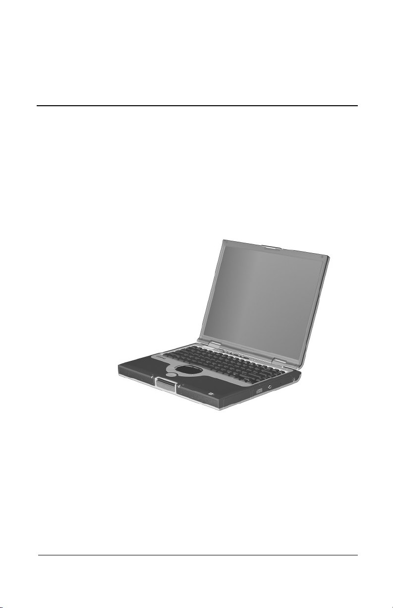
The Compaq Evo Notebook N1015 Series, Evo Notebook N1005
Series, and Presario 900 Series Mobile PCs offer advanced
modularity, AMD Athlon and Duron processors, industry-leading
Accelerated Graphics Port (AGP) implementation, and extensive
multimedia support.
Figure 1-1. Compaq Evo Notebook N1015 Series,
Evo Notebook N1005 Series, and Presario 900 Series
Mobile PCs
Maintenance and Service Guide 1–1
Page 7

Product Description
1.1 Models
Computer models are shown in Tables 1-1 through 1-4.
Table 1-1
Compaq Evo Notebook N1015, Notebook N1005, and Presario 900
Model Naming Conventions
Key
P900 P 220 P5 40 V C 51 O XXXXXX-XXX
123456789 10
Key Description Options
1 Brand/Series
designator
2 Processor type A = AMD Athlon XP+ D = AMD Duron
3 Processor speed 167 = 1.67 GHz
4Display type/
size/resolution
5 Hard drive size 40 = 40 GB
6 Optical drive
designator
7 Integrated
communication
8 RAM 51 = 512 MB 25 = 256 MB
9 Operating system O = Windows XP Pro E = Windows XP
10 SKU#
E = Evo
P = Presario
160 = 1.60 GHz
153 = 1.53 GHz
147 = 1.47 GHz
X = XGA
(1024 × 768)
30 = 30 GB
V = DVD-ROM drive
W = DVD-RW drive
M = Modem
0 = None
7 = 802.11b wireless
LAN
1015 = 1015 Series
1005 = 1005 Series
900 = 900 Series
140 = 1.40 GHz
130 = 1.30 GHz
120 = 1.20 GHz
5 = 15.x-inch
4 = 14.x-inch
20 = 20 MB
D = CD-ROM drive
R = CD-RW drive
C = Modem/NIC
combination card
Home
1–2 Maintenance and Service Guide
Page 8
Product Description
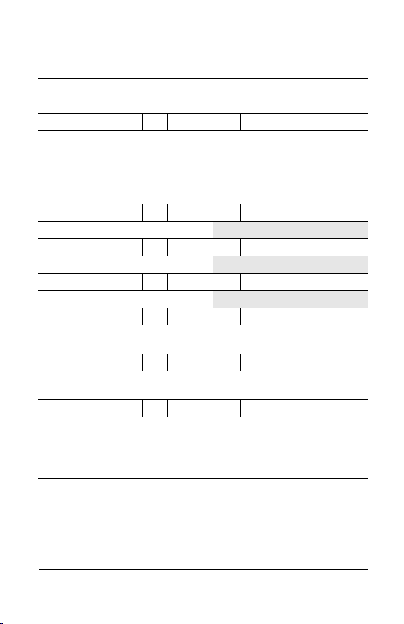
Table 1-2
Compaq Evo Notebook N1015 Series Models
The following Evo Notebook N1015 Series model uses config. code KSXZ and
features:
■ TouchPad
■ 8-cell, 4.0-Ah lithium ion (Li ion) battery pack
■ 2-year warranty
■ diskette drive
N1015 A 130 X4 20 D C 12 E
Germany 470046-613
The following Evo Notebook N1015 Series model uses config. code KSBZ and
features:
■ TouchPad
■ 8-cell, 4.0-Ah lithium ion (Li ion) battery pack
■ 1-year warranty
■ diskette drive
N1015 A 167 X5 40 W C 25 O
Asia Pacific
Australia/New Zealand
India
470046-548
470049-166
470046-554
Korea
Thailand
N1015 A 167 X5 40 V C 25 O
470046-555
470046-547
Taiwan 470046-559
N1015 A 153 X5 40 W C 25 O
French Canada 470045-404 United States 470045-397
N1015 A 153 X5 40 W C 25 O
United States 470046-091 includes Microsoft Office Pro
software
N1015 A 153 X4 30 V C 25 O
Asia Pacific
Australia/New Zealand
India
470046-549
470046-545
470046-552
Korea
Ta i wa n
Thailand
470046-557
470046-558
470046-546
Maintenance and Service Guide 1–3
Page 9

Product Description
Table 1-2
Compaq Evo Notebook N1015 Series Models
N1015 A 153 X4 20 R C 25 O
Asia Pacific 470047-372
N1015 A 140 X5 30 R C 25 O
Latin America 470050-296 United States NEW - 0.2LA
N1015 A 140 X4 30 V C 25 O
French Canada 470045-406 United States 470045-407
N1015 A 140 X4 30 V C 25 O
United States 470046-093 includes Microsoft Office Pro
software
N1015 A 140 X4 30 D 7 25 O
French Canada 470046-577 United States 470046-574
N1015 A 140 X4 30 D 7 25 O
United States 470046-576 includes Microsoft Office SE
software
(Continued)
N1015 A 130 X4 20 W C 25 O
Japan 470049-213 Japan English 470049-215
N1015 A 130 X4 20 R C 25 O
Japan 470049-211 Japan English 470049-216
N1015 A 130 X4 20 R C 12 O
Japan
N1015 A 130 X4 20 R C 12 O
Japan NEW - 0.4AP Japan (English) NEW - 0.4AP
NEW - 0.3AP Japan (English) NEW - 0.3AP
1–4 Maintenance and Service Guide
Page 10
Table 1-2
Compaq Evo Notebook N1015 Series Models
N1015 A 130 X4 20 D C 12 E
Product Description
(Continued)
Belgium
Czech Republic
Denmark
European
International
France
Greece/Poland
Hungary
Israel
Italy
The Netherlands
470046-581
470046-582
470046-583
470046-584
470046-585
470046-586
470046-587
470046-588
470046-589
470046-590
Norway
Portugal
Russia
Saudi Arabia
Slovenia
Spain
Sweden/Finland
Switzerland
Tu r ke y
United Kingdom
N1015 A 120 X4 20 D C 25 O
Latin America
NEW - 0.4LA United States NEW - 0.4LA
N1015 A 120 X4 20 D C 12 E
Latin America
NEW - 0.3LA United States NEW - 0.3LA
N1015 A 120 X3 20 R C 25 O
Asia Pacific
Australia/New Zealand
470049-163
470046-544
India
Hong Kong
N1015 A 120 X3 20 R C 12 O
Asia Pacific
India
470046-550
470046-551
Hong Kong 470046-561
N1015 A 120 X3 20 D 7 12 E
470046-591
470046-592
470046-600
470046-580
470046-602
470046-603
470046-605
470046-607
470046-611
470046-612
470049-164
470049-165
United States 470046-575
N1015 A 120 X3 20 D C 25 O
Latin America 470050-294 United States
NEW - 0.1LA
Maintenance and Service Guide 1–5
Page 11
Product Description
Table 1-2
Compaq Evo Notebook N1015 Series Models
N1015 A 120 X3 20 D C 12 E
Latin America 470050-688
N1015 A 120 X3 20 D 0 12 E
(Continued)
French Canada
United States
470046-578
470046-573
United States
GEM/NAFTA
470047-371
Table 1-3
Compaq Evo Notebook N1005 Series Models
The following Evo Notebook N1005 Series models use config. code KSXZ and
features:
■ TouchPad
■ 8-cell, 4.0-Ah lithium ion (Li ion) battery pack
■ 2-year warranty
■ diskette drive
N1005 A 153 X5 30 W C 25 O
Germany 470041-860
N1005 A 147 X4 20 V C 25 O
Germany 470041-859
1–6 Maintenance and Service Guide
Page 12
Product Description
Table 1-3
Compaq Evo Notebook N1005 Series Models
The following Evo Notebook N1005 Series models use config. code KSBZ and
features:
■ TouchPad
■ 8-cell, 4.0-Ah lithium ion (Li ion) battery pack
■ 1-year warranty
■ diskette drive
N1005 A 153 X5 30 W C 25 O
(Continued)
Belgium
Czech Republic
Denmark
European
International
France
Greece/Poland
Hungary
Israel
Italy
The Netherlands
470041-815
470041-818
470041-819
470041-822
470041-823
470041-826
470041-827
470041-830
470041-831
470041-834
Norway
Portugal
Russian
Saudi Arabia
Slovenia
Spain
Sweden/Finland
Switzerland
Tu r ke y
United Kingdom
N1005 A 147 X4 20 V C 25 O
Belgium
Czech Republic
Denmark
European
International
France
Greece/Poland
Hungary
Israel
Italy
The Netherlands
470041-816
470041-817
470041-820
470041-821
470041-824
470041-825
470041-828
470041-829
470041-832
470041-833
Norway
Portugal
Russia
Saudi Arabia
Slovenia
Spain
Sweden/Finland
Switzerland
Tu r ke y
United Kingdom
470041-835
470041-838
470041-839
470041-814
470041-842
470041-843
470041-846
470041-848
470041-851
470041-852
470041-836
470041-837
470041-840
470041-813
470041-841
470041-844
470041-845
470041-849
470041-850
470041-853
Maintenance and Service Guide 1–7
Page 13
Product Description
Table 1-4
Compaq Presario 900 Series Mobile PC Models
The following Presario 900 Series Mobile PC models use config. code KSXZ
and features:
■ TouchPad
■ 8-cell, 4.0-Ah lithium ion (Li ion) battery pack
■ 2-year warranty
■ diskette drive
P920 A 167 X5 30 W C 25 E
Belgium
Germany
470045-618
470045-624
Norway NEW - 1.3EA
P917 A 153 X5 30 W C 51 E
Germany 470046-503
P918 A 153 X5 30 W C 25 E
Belgium 470046-500 Germany 470047-369
P905 A 153 X5 30 W C 25 E
Belgium
Denmark
Germany
Italy
The Netherlands
470036-882
470036-883
470037-069
470037-072
470037-075
Norway
Portugal
Spain
Sweden/Finland
470037-078
470037-517
470037-521
470037-083
P915 A 153 X4 30 W C 25 E
Belgium
Germany
470045-617
470045-623
Norway 470045-632
P911 A 153 X4 20 W C 25 E
Germany 470046-502
P904 A 153 X4 20 W C 25 E
Belgium
Denmark
Germany
Italy
The Netherlands
470038-081
470038-082
470038-083
470038-084
470038-085
Norway
Portugal
Spain
Sweden/Finland
470038-086
470038-087
470038-088
470038-089
1–8 Maintenance and Service Guide
Page 14
Table 1-4
Compaq Presario 900 Series Mobile PC Models
P910 A 140 X4 20 V C 12 E
Product Description
(Continued)
Belgium
Germany
470045-616
470045-622
Norway 470045-633
P902 A 130 X5 30 W C 25 E
Belgium
Denmark
Germany
Italy
The Netherlands
470037-046
470037-068
470037-071
470037-074
470037-077
Norway
Portugal
Spain
Sweden/Finland
470037-080
470037-516
470037-520
470037-081
P908 A 130 X4 20 W C 25 E
Belgium 470046-499 Norway 470050-687
P906 A 130 X4 20 W C 25 E
United States 470047-897
P907 A 130 X4 20 V C 25 E
Germany 470046-501 Norway 470046-506
P901 A 120 X5 20 W C 25 E
Belgium
Denmark
Germany
Italy
The Netherlands
470037-045
470037-067
470037-070
470037-073
470037-076
Norway
Portugal
Spain
Sweden/Finland
470037-079
470037-515
470037-519
470037-082
The following Presario 900 Series Mobile PC model uses config. code KSB1
and features:
■ TouchPad
■ 8-cell, 4.0-Ah lithium ion (Li ion) battery pack
■ 1-year warranty
■ diskette drive
P900 A 147 X5 30 W C 25 E
United States 470037-278
Maintenance and Service Guide 1–9
Page 15
Product Description
Table 1-4
Compaq Presario 900 Series Mobile PC Models
The following Presario 900 Series Mobile PC model uses config. code KSB2
and features:
■ TouchPad
■ 8-cell, 4.0-Ah lithium ion (Li ion) battery pack
■ 1-year warranty
■ diskette drive
P904 A 130 X5 20 W C 51 E
United States 470038-539
The following Presario 900 Series Mobile PC models use config. code KSBZ
and features:
■ TouchPad
■ 8-cell, 4.0-Ah lithium ion (Li ion) battery pack
■ 1-year warranty
■ diskette drive
P920 A 167 X5 40 W C 51 E
Canada (English)
French Canada
470046-484
470046-485
United States 470045-486
(Continued)
P922 A 167 X5 30 W C 51 E
The Netherlands
Sweden/Finland
470048-558
470048-559
United Kingdom 470046-497
P955 A 167 X5 30 W C 25 E
Asia Pacific 470049-161 Korea 470048-552
P925 A 167 X5 30 W C 25 O
European
470049-156
International
1–10 Maintenance and Service Guide
Page 16
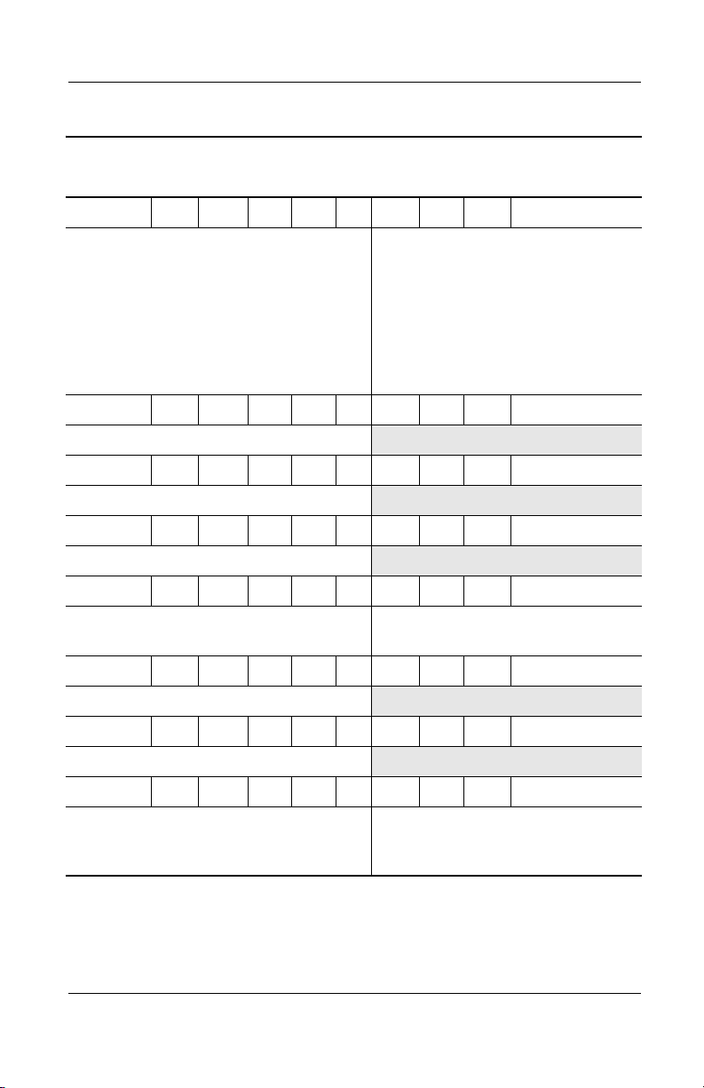
Table 1-4
Compaq Presario 900 Series Mobile PC Models
P920 A 167 X5 30 W C 25 E
Product Description
(Continued)
Denmark
European
International
France
Greece/Poland
Hungary
Israel
Italy
P950 A 167 X4 30 W C 25 E
Hong Kong 470048-551
P945 A 167 X4 30 V C 25 E
Taiwan 470048-554
P918 A 160 X5 40 W C 51 E
United States 470045-488
P915 A 153 X5 40 W C 25 E
Canada (English)
French Canada
P914 A 153 X5 40 W C 25 E
France 470047-904
P930 A 153 X5 30 W C 25 E
India 470047-673
NEW - 0.7EA
470045-495
470045-500
470045-501
470045-507
470045-508
470048-563
470046-483
470046-486
The Netherlands
Portugal
Russia
Saudi Arabia
Spain
Sweden/Finland
Switzerland
United Kingdom
United States 470046-485
470048-557
470048-427
470045-514
470045-494
470048-428
470050-685
470045-515
470045-520
P918 A 153 X5 30 W C 25 E
European
International
Greece/Poland
470047-903
470046-494
Switzerland
United Kingdom
470046-498
470047-367
Maintenance and Service Guide 1–11
Page 17
Product Description
Table 1-4
Compaq Presario 900 Series Mobile PC Models
P905 A 153 X5 30 W C 25 E
(Continued)
European
International
France
Germany
Hungary
Israel
P917 A 153 X5 30 W C 25 O
European
International
P906 A 153 X5 30 W C 25 O
European
International
P912 A 153 X5 20 V C 25 E
The Netherlands 470048-555
P920 A 153 X4 40 W C 25 E
Latin America 470045-489 Latin America
P943 A 153 X4 30 W C 25 E
Thailand 470050-686
P915 A 153 X4 30 W C 25 E
Denmark
European
International
France
Greece/Poland
Hungary
P907 A 153 X4 30 W C 25 E
470037-133
470037-134
470037-138
470040-102
470037-305
470049-153
470039-301
470048-564
470045-496
470045-499
470045-503
470045-506
Russia
Saudi Arabia
Switzerland
Tu r ke y
United Kingdom
NAFTA
Israel
The Netherlands
Russia
Saudi Arabia
Sweden/Finland
Switzerland
United Kingdom
470037-140
470037-127
470037-345
470037-151
470037-152
470045-492
470045-509
470048-556
470045-513
470045-493
470048-741
470045-516
470045-519
Hong Kong 470045-539
1–12 Maintenance and Service Guide
Page 18
Product Description
Table 1-4
Compaq Presario 900 Series Mobile PC Models
P906 A 153 X4 30 W C 25 E
Korea 470037-514
P905 A 153 X4 30 W C 25 E
Australia/New Zealand 470037-311
P904 A 153 X4 30 W C 25 E
Taiwan 470045-531
P916 A 153 X4 30 W C 25 O
French Canada 470046-482 United States 470046-475
P940 A 153 X4 30 V C 25 E
Taiwan 470048-553
P927 A 153 X4 30 V C 25 E
India 470050-293
P904 A 153 X4 20 W C 25 E
(Continued)
European
International
France
Germany
Israel
P903 A 153 X4 20 W C 25 E
Korea 470038-111
P935 A 153 X4 20 V C 25 E
Hong Kong 470048-550
P905 A 153 X4 20 V C 25 E
Asia Pacific
Australia/New Zealand
470038-102
470038-103
470038-104
470038-105
470037-313
470037-310
Russia
Saudi Arabia
Switzerland
Tu r ke y
United Kingdom
Korea
Thailand
470038-106
470038-101
470038-107
470038-108
470038-109
470037-312
470037-314
Maintenance and Service Guide 1–13
Page 19
Product Description
Table 1-4
Compaq Presario 900 Series Mobile PC Models
P925 A 153 X4 20 V C 12 E
(Continued)
People’s Republic of
470048-549
China
P905 A 147 X5 30 W C 25 E
Brazil
Hong Kong
Latin America
470037-309
470037-289
470037-277
Latin America
(NAFTA)
Ta i wa n
470037-288
470037-315
P900 A 147 X5 30 W C 25 E
Canada English 470037-117 French Canada 470037-279
P912 A 140 X4 40 W C 25 E
United States 470045-487
P905 A 140 X4 30 R C 12 E
Latin America
NEW - 0.2LA Latin America
NEW - 0.2LA
(NAFTA)
P910 A 140 X4 20 W C 25 E
Australia/New Zealand 470047-670
P921 A 140 X4 20 V C 12 E
Asia Pacific 470050-291 Australia/New
470050-290
Zealand
P910 A 140 X4 20 V C 12 E
Denmark
European
International
France
Greece/Poland
Hungary
470048-565
470045-497
470045-498
470045-504
470045-505
Israel
Portugal
Russia
Saudi Arabia
Switzerland
United Kingdom
470045-510
470048-425
470045-512
470045-350
470045-351
470045-518
P920 A 140 X4 20 R C 12 E
Asia Pacific
India
470047-672
470050-289
Thailand 470047-671
1–14 Maintenance and Service Guide
Page 20
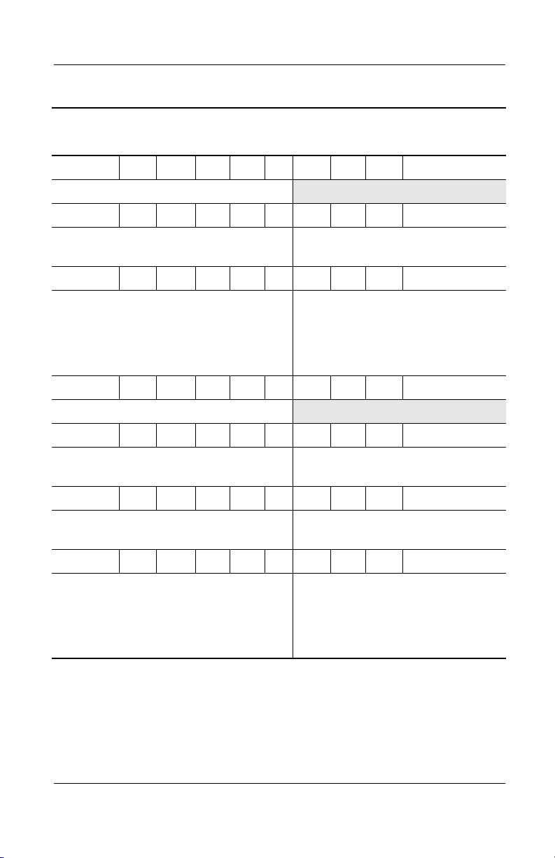
Table 1-4
Compaq Presario 900 Series Mobile PC Models
P923 A 140 X4 20 D C 25 E
Korea 470050-292
P900 A 140 X3 30 R C 12 E
Product Description
(Continued)
Latin America 470045-490 Latin America
NAFTA
P902 A 130 X5 30 W C 25 E
European
International
France
Germany
Israel
P902 A 130 X5 20 W C 25 E
France 470040-350
P910 A 130 X4 30 W C 25 E
Canada (English)
French Canada
P905 A 130 X4 30 V C 25 E
Canada (English)
French Canada
P908 A 130 X4 20 W C 25 E
Denmark
European
International
France
Greece/Poland
470037-132
470037-135
470037-137
470037-304
470046-477
470046-478
470046-476
470046-479
NEW - 0.9EA
470047-902
470046-488
470047-366
Russia
Saudi Arabia
Switzerland
Tu r ke y
United Kingdom
United States 470045-484
United States 470045-353
Italy
Spain
Sweden/Finland
Switzerland
United Kingdom
470045-491
470037-141
470037-126
470037-344
470037-150
470037-153
470050-681
470048-424
470050-682
470046-489
470046-495
Maintenance and Service Guide 1–15
Page 21
Product Description
Table 1-4
Compaq Presario 900 Series Mobile PC Models
P907 A 130 X4 20 V C 25 E
(Continued)
European
International
France
Greece/Poland
Hungary
Israel
P905 A 130 X4 20 V C 25 E
Hong Kong 47046-481
P902 A 130 X4 20 V C 25 E
Australia/New Zealand 470038-110
P903 A 130 X4 20 V C 12 E
Taiwan 470045-529
P902 A 130 X4 20 V C 12 E
Asia Pacific
Australia/New Zealand
P901 A 130 X4 20 D C 12 E
Asia Pacific
Australia/New Zealand
P901 A 120 X5 20 W C 25 E
European
International
France
Germany
Israel
470047-365
470046-487
470046-493
470047-900
470047-901
470045-480
470045-524
470045-526
470045-523
470037-131
470037-136
470037-120
470037-303
Italy
Saudi Arabia
Spain
Sweden/Finland
Switzerland
Hong Kong 470045-527
Thailand 470045-525
Russia
Saudi Arabia
Switzerland
Tu r ke y
United Kingdom
470048-562
470047-899
470048-423
470048-561
470046-490
470037-142
470037-122
470037-343
470037-149
470037-154
1–16 Maintenance and Service Guide
Page 22

Table 1-4
Compaq Presario 900 Series Mobile PC Models
P909 A 120 X4 20 R C 12 E
Portugal 470050-684
P900 A 120 X4 20 D C 12 E
Product Description
(Continued)
Asia Pacific
Australia/New Zealand
1.2 Features
The notebook has the following features:
■ AMD Athlon XP+ 1.67-, 1.60-, 1.53-, 1.47-, 1.40-, 1.30-, or
1.20-GHz processors, or AMD Duron 1.30-GHz processor,
varying by notebook model
■ ATI P7 graphics accelerator with 32 MB of shared
Synchronous DRAM (SDRAM) and 4X AGP graphics card
■ 256-MB high-performance SDRAM, expandable to 1.0 GB
■ Microsoft Windows XP Home or Windows XP Professional,
varying by computer model
■ 15.0-, 14.1-, 13.3-inch XGA (1024 × 768), TFT display with
over 16.7 million colors, varying by computer model
■ Full-size Windows 98 keyboard with TouchPad pointing
device
■ Network interface card (NIC) integrated on the system board,
with a mini PCI V.92 modem
■ Integrated wireless support of 802.11b and Bluetooth devices
through MultiPort
■ Support for one Type I or II PC Card slot with support for
both 32-bit CardBus and 16-bit PC Cards
■ External 90 W AC adapter with power cord
■ 8-cell Li ion battery pack
470040-356
470040-354
Korea
Thailand
470040-357
470040-355
Maintenance and Service Guide 1–17
Page 23

Product Description
■ 40-, 30-, or 20-GB high-capacity hard drive, varying by
computer model
■ 1.44-MB diskette drive
■ Support for the following drives through the fixed optical
drive:
❏ 24X Max CD-ROM drive
❏ 16X Max CD-RW drive
❏ 8X Max DVD-ROM drive
❏ 8X Max DVD-ROM/CD-RW combination drive
■ Connectors for:
❏ 1394 digital input
❏ Stereo line out/headphone
❏ Mono microphone
❏ AC power
❏ Universal serial bus
❏ External monitor
❏ S-video
❏ External keyboard/mouse
❏ Parallel devices
❏ RJ-45 network
❏ RJ-11 modem
■ JBL Pro stereo speakers with bass reflex
■ Dolby Digital certified sound
1.3 Clearing a Password
If the notebook you are servicing has an unknown password,
follow these steps to clear the password. These steps also
clear CMOS:
1. Prepare the computer for disassembly (refer to Section 5.3,
“Preparing the Computer for Disassembly,” for more
information).
1–18 Maintenance and Service Guide
Page 24

2. Remove the RTC battery (refer to Section 5.7, “Disk Cell
RTC Battery”).
3. Wait approximately five minutes.
4. Replace the RTC battery and reassemble the computer.
5. Connect AC power to the computer. Do not reinsert any
battery packs at this time.
6. Turn on the computer.
All passwords and all CMOS settings have been cleared.
1.4 Power Management
The notebook comes with power management features that
extend battery operating time and conserve power. The notebook
supports the following power management features:
■ Standby
■ Hibernation
Product Description
■ Setting customization by the user
■ Hotkeys for setting level of performance
■ Smart battery that provides an accurate battery power gauge
■ Battery calibration
■ Lid switch suspend/resume
■ Power/Suspend button
■ Advanced Configuration and Power Management (ACP)
compliance
Maintenance and Service Guide 1–19
Page 25
Product Description
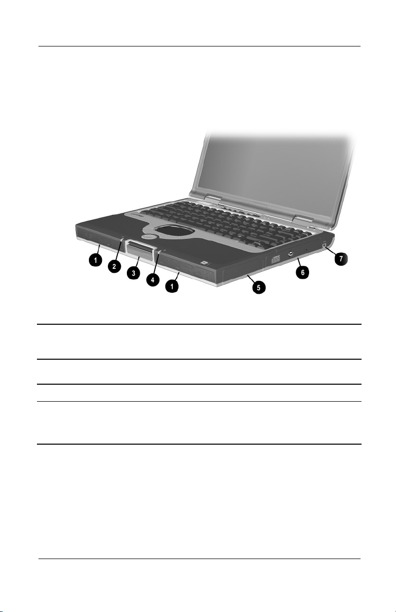
1.5 Computer External Components
The external components on the front and right side of the
computer are shown in Figure 1-2 and described in Table 1-4.
.
Figure 1-2. Front and Right Side Components
Table 1-4
Front and Right Side Components
Item Component Function
1 Stereo speakers (2) Produce stereo sound.
2 Power/Standby light On: Power is turned on.
Off: Power is turned off.
Blinking: Computer is in Standby mode.
1–20 Maintenance and Service Guide
Page 26

Product Description
Table 1-4
Front and Right Side Components
Item Component Function
3 Display release latch Opens the computer.
4 Battery light On: A battery pack is charging.
Blinking: A battery pack that is the only
available power source has reached a
low-battery condition.
5 Battery bay Accepts an 8-cell Li ion battery pack.
6 Optical drive bay Accepts a CD-ROM, CD-RW, DVD-ROM, or
DVD/CD-RW combination drive.
7 1394 jack Connects IEEE 1394-compliant products,
such as digital camcorders, video editing
equipment, VCRs, cameras, and audio
players. A 1394 firewire cable is required for
use with this jack.
(Continued)
Maintenance and Service Guide 1–21
Page 27
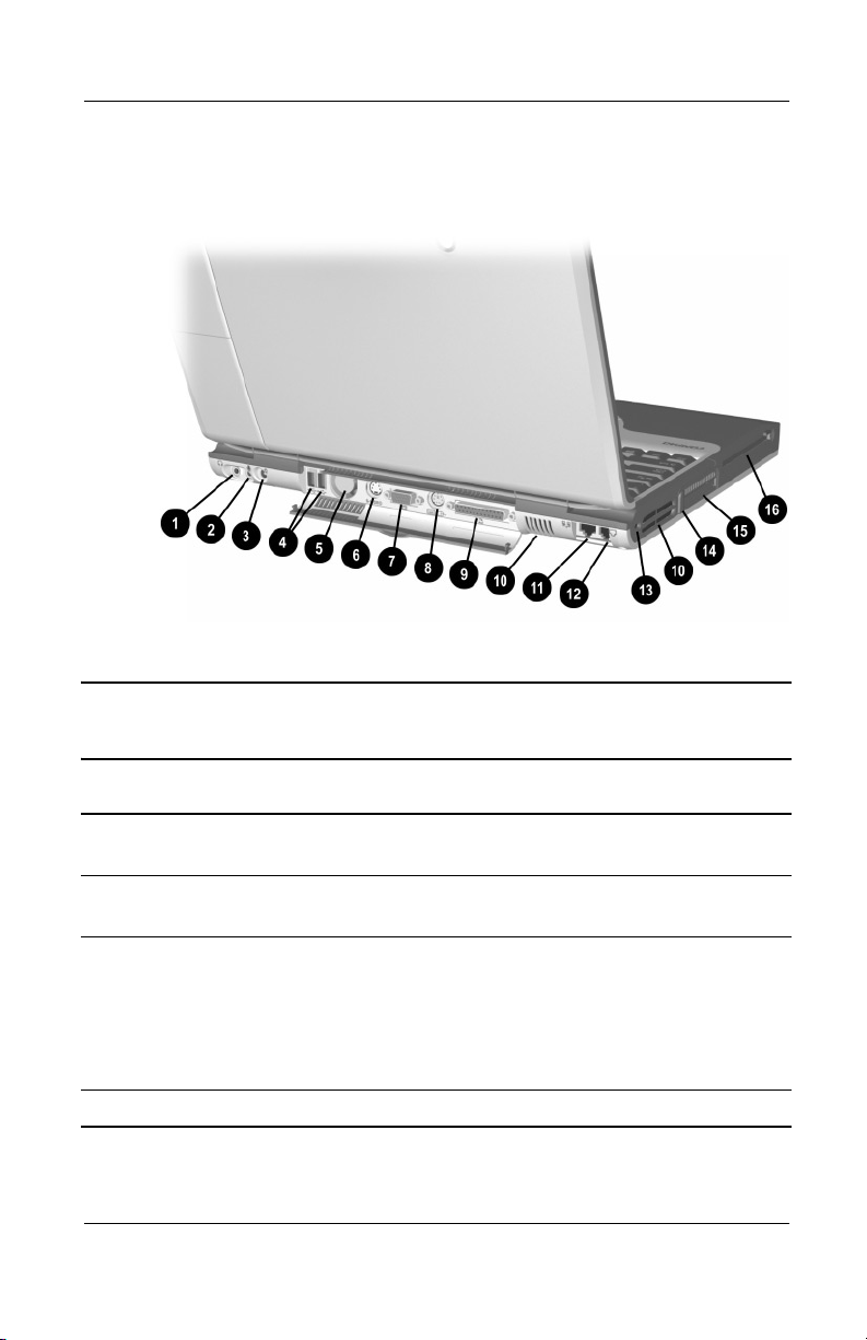
Product Description
The computer rear panel and left side components are shown in
Figure 1-3 and described in Table 1-5.
Figure 1-3. Rear Panel and Left Side Components
Table 1-5
Rear Panel and Left Side Components
Item Component Function
1 Stereo speaker/
headphone jack
2 Mono microphone jack Connects a mono microphone, disabling the
3 DC power jack Connects any one of the following:
4 USB connectors (2) Connect USB devices.
1–22 Maintenance and Service Guide
Connects stereo speakers, headphones,
headset, or television audio.
built-in microphone.
■ AC adapter
■ Optional automobile power
adapter/charger
■ Optional aircraft power adapter
Page 28

Product Description
Table 1-5
Rear Panel and Left Side Components
Item Component Function
5 Fan Provides airflow to cool internal
components.
6 S-Video connector Connects a television, VCR, camcorder, or
overhead projector.
7 External monitor
connector
Connects an external monitor or overhead
projector.
(Continued)
8 External
keyboard/mouse
connector
9 Parallel connector Connects a parallel device.
10 Vents Allow airflow to cool internal components.
CAUTION: To prevent damage, the computer shuts down if an
Ä
overheating condition occurs. Do not block the cooling vent.
Avoid placing the computer on a blanket, rug, or other flexible
surface that may cover the vent area.
11 RJ-45 network jack Connects the network cable. A network
12 RJ-11 modem jack Connects the modem cable to an internal
13 Security cable slot Attaches an optional security cable to
14 PC Card eject button Ejects a PC Card from the PC Card slot.
15 PC Card slot Supports a 32-bit (CardBus) or 16-bit PC
16 Diskette drive Accepts diskettes.
Connects an optional full-sized keyboard or
mouse. An optional splitter/adapter allows
both an external keyboard and mouse to be
used at the same time.
cable is not included with the computer.
modem. A modem cable is included with
internal modem models.
the computer.
Card.
Maintenance and Service Guide 1–23
Page 29
Product Description
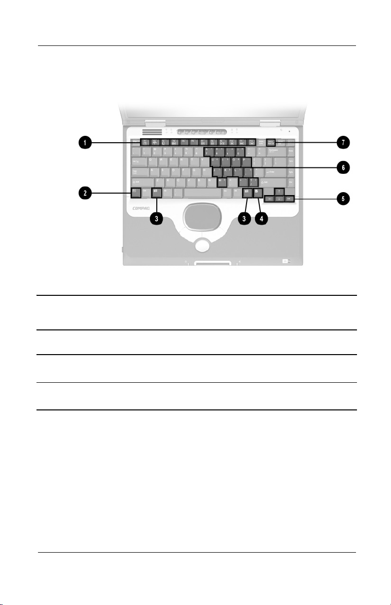
The computer keyboard components are shown in Figure 1-4 and
described in Table 1-6.
Figure 1-4. Keyboard Components
Table 1-6
Keyboard Components
Item Component Function
1 F1 through F12
function keys
2 Fn key Used with hotkeys to perform preset hotkey
1–24 Maintenance and Service Guide
Perform preset functions.
functions.
Page 30

Product Description
Table 1-6
Keyboard Components
Item Component Function
3 Windows logo keys Display the Windows Start menu.
4 Windows application
key
5 Cursor control keys Move the cursor around the screen.
Displays a menu when using a Microsoft
application. The menu is the same one that
is displayed by pressing the right mouse
button.
(Continued)
6 Embedded numeric
keypad
7
Num lock key Turns on the numeric lock function.
Converts keys to numeric keypad.
On: Num lock is on and the embedded
numeric keypad is enabled.
Maintenance and Service Guide 1–25
Page 31

Product Description
The computer top components are shown in Figure 1-5 and
described in Table 1-7.
Figure 1-5. Top Components
Table 1-7
Top Components
Item Component Function
1 Power light On: Power is turned on.
Blinking: Computer is in Standby. The
power light also blinks if a battery pack that
is the only available power source reaches
a low-battery condition.
2 Num lock light On:
3 Easy Access
Buttons (3)
1–26 Maintenance and Service Guide
Num lock is on and the embedded
numeric keypad is enabled.
Provide quick access to the Internet. Refer
to the Hardware Guide that ships with the
computer for information about these
buttons.
Page 32

Product Description
Table 1-7
Top Components
Item Component Function
4 Power button Turns on the computer. Use the operating
system Shut Down command to turn off the
computer.
5 Digital audio button Launches Windows Media Player to play
MP3 music.
6 Volume control buttons Adjust the volume of the stereo speakers.
7 Caps lock light On: Caps lock is on.
8 Drive indicator light Turns on when the hard drive, CD-, or
DVD-ROM drive is accessed.
9 Display lid switch Turns off the computer display if the
computer is closed while on.
10 TouchPad Moves the mouse cursor, selects, and
activates.
11 TouchPad buttons Function like the left and right mouse
buttons on an external mouse.
(Continued)
12 Power/Standby light On: Power is turned on.
Off: Power is turned off.
Blinking: Computer is in Standby mode.
13 EasyScroll Scrolls the screen left, right, up, and down.
14 Battery power light On: A battery pack is charging.
Blinking: A battery pack that is the only
available power source has reached a
low-battery condition.
Maintenance and Service Guide 1–27
Page 33

Product Description
The external components on the bottom of the computer are
shown in Figure 1-6 and described in Table 1-8.
Figure 1-6. Bottom Components
Table 1-8
Bottom Components
Item Component Function
1 Hard drive retention screw Secures the hard drive to the
computer.
2 Hard drive bay Supports the primary hard drive.
The hard drive is secured to the
computer by one screw.
3 Mini PCI communications
compartment
Contains the mini PCI modem
card.
1–28 Maintenance and Service Guide
Page 34

Product Description
Table 1-8
Bottom Components
Item Component Function
4 RJ-11 modem jack Connects the modem cable to an
5 RJ-45 network jack Connects the network cable. A
6 Connector cover Protects the parallel, external
7 Certificate of Authenticity label Contains the Product Key, which
8 Memory expansion
compartment
(Continued)
internal modem. A modem cable is
included with internal modem
models.
network cable is not included with
the computer.
monitor, external keyboard/mouse,
and USB connectors.
may need to be entered before
using some Windows operating
systems.
Covers the memory expansion
compartment that contains two
memory expansion slots for
memory expansion boards.
9 Battery pack release switch Releases the battery pack from
the battery compartment.
10 Battery bay Accepts an 8-cell Li ion
battery pack.
11 Serial number Identifies the computer; needed
when you call Compaq customer
support.
Maintenance and Service Guide 1–29
Page 35

Product Description
1.6 Design Overview
This section presents a design overview of key parts and features
of the computer. Refer to Chapter 3, “Illustrated Parts Catalog,”
to identify replacement parts and Chapter 5, “Removal and
Replacement Procedures,” for disassembly steps. The system
board provides the following device connections:
■ Memory expansion board
■ Hard drive
■ Display
■ Keyboard/TouchPad or pointing stick
■ Audio
■ AMD Athlon and Duron processors
■ Fan
■ PC Card
■ Modem or modem/NIC
The computer uses an electrical fan for ventilation. The fan is
controlled by a temperature sensor and is designed to turn on
automatically when high-temperature conditions exist. These
conditions are affected by high external temperatures, system
power consumption, power management/battery conservation
configurations, battery fast charging, and software applications.
Exhaust air is displaced through the ventilation grill located on
the left side of the computer.
CAUTION: To properly ventilate the computer, allow at least a
Ä
7.6-cm (3-inch) clearance on the left and right sides of the
computer.
1–30 Maintenance and Service Guide
Page 36

Troubleshooting
WARNING: Only authorized technicians trained by Compaq should
Å
repair this equipment. All troubleshooting and repair procedures
are detailed to allow only subassembly/module level repair.
Because of the complexity of the individual boards and
subassemblies, no one should attempt to make repairs at the
component level or make modifications to any printed wiring board.
Improper repairs can create a safety hazard. Any indication of
component replacement or printed wiring board modification may
void any warranty or exchange allowances.
2.1 Computer Setup and Diagnostics Utilities
Selecting Computer Setup or Compaq Diagnostics
2
The computer features two Compaq system management utilities:
■ Computer Setup—A system information and customization
utility that can be used even when your operating system is
not working or will not load. This utility includes settings that
are not available in Windows.
Maintenance and Service Guide 2–1
Page 37

Troubleshooting
■ Compaq Diagnostics—A system information and diagnostic
utility that is used within your Windows operating system.
Use this utility whenever possible to:
❏ Display system information.
❏ Test system components.
❏ Troubleshoot a device configuration problem in
Windows 2000, Windows XP Professional, or
Windows XP Home.
Using Computer Setup
Information and settings in Computer Setup are accessed from
the File, Security, or Advanced menus:
1. Turn on or restart the computer. Press
F10 while the
F10 = ROM Based Setup message is displayed in the
lower-left corner of the screen.
❏ To change the language, press F2.
❏
To view navigation information, press F1.
❏
To return to the Computer Setup menu, press esc.
2. Select the File, Security, or Advanced menu.
3. To close Computer Setup and restart the computer:
❏ Select File > Save Changes and Exit and press enter.
or
❏ Select File > Ignore Changes and Exit and press enter.
4. When you are prompted to confirm your action, press F10.
2–2 Maintenance and Service Guide
Page 38

Troubleshooting
Selecting from the File Menu
Table 2-1
File Menu
Select To Do This
System Information ■ View identification information about the
computer, a docking base, and any battery
packs in the system.
■ View specification information about the
processor, memory and cache size, and
system ROM.
Save to Floppy Save system configuration settings to a diskette.
Restore from Floppy Restore system configuration settings from a
diskette.
Restore Defaults Replace configuration settings in Computer
Setup with factory default settings. (Identification
information is retained.)
Ignore Changes and Exit Cancel changes entered during the current
session, then exit and restart the computer.
Save Changes and Exit Save changes entered during the current
session, then exit and restart the computer.
Maintenance and Service Guide 2–3
Page 39

Troubleshooting
Selecting from the Security Menu
Table 2-2
Security Menu
Select To Do This
Setup Password Enter, change, or delete a setup password.
(The setup password is called an administrator
password in Compaq Computer Security, a
program accessed from the Windows Control
Panel.)
Power-on Password Enter, change, or delete a power-on password.
DriveLock Passwords Enable/disable DriveLock; change a DriveLock
User or Master password.
DriveLock Settings are accessible only
✎
when you enter Computer Setup by
turning on (not restarting) the computer.
Password Options
Password options can be
selected only when a
power-on password has
been set.
Device Security Enable/disable:
System IDs Enter identification numbers for the computer,
*Not applicable to SuperDisk LS-120 drives.
2–4 Maintenance and Service Guide
Enable/disable:
■ QuickLock
■ QuickLock on Standby
■ QuickBlank
To enable QuickLock on Standby or
✎
QuickBlank, you must first enable
QuickLock.
■ Ports or diskette drives*
■ Diskette write*
■ CD-ROM or diskette startup
Settings for a DVD-ROM can be
✎
entered in the CD-ROM field.
a docking base, and all battery packs in the
system.
Page 40

Selecting from the Advanced Menu
Table 2-3
Advanced Menu
Select To Do This
Language (or press F2) Change the Computer Setup language.
Boot Options Enable/disable:
■ QuickBoot, which starts the computer more
quickly by eliminating some startup tests.
(If you suspect a memory failure and want to
test memory automatically during startup,
disable QuickBoot.)
■ MultiBoot, which sets a startup sequence
that can include most bootable devices and
media in the system.
Device Options
■ Enable/disable the embedded numeric
keypad at startup.
■ Enable/disable multiple standard pointing
devices at startup. (To set the computer to
support only a single, usually nonstandard,
pointing device at startup, select Disable.)
■ Enable/disable USB legacy support for a
USB keyboard. (When USB legacy support
is enabled, the keyboard works even when a
Windows operating system is not loaded.)
■ Set an optional external monitor or overhead
projector connected to a video card in a
docking base as the primary device.
(When the computer display is set as
secondary, the computer must be shut down
before undocking from a docking base.)
Troubleshooting
Maintenance and Service Guide 2–5
Page 41

Troubleshooting
Table 2-3
Advanced Menu
Select To Do This
(Continued)
Device Options
(continued)
■ Change the parallel port mode from
Enhanced Parallel Port (EPP, the default
setting) to standard, bidirectional, EPP or
Enhanced Capabilities Port (ECP).
■ Set video-out mode to NTSC (default), PAL,
NTSC-J, or PAL-M.*
■ Enable/disable all settings in the SpeedStep
window. (When Disable is selected, the
computer runs in Battery Optimized mode.)
■ Specify how the computer recognizes
multiple identical docking bases that are
identically equipped. (Select Disable to
recognize the docking bases as a single
docking base; select Enable to recognize
the docking bases individually, by serial
number.)
■ Enable/disable the reporting of the
processor serial number by the processor
to the software.
HDD Self Test Options Run a quick comprehensive self test on hard
drives in the system that support the test
features.
*Video modes vary even within regions. However, NTSC is common in
North America; PAL, in Europe, Africa, and the Middle East; NTSC-J, in Japan;
and PAL-M, in Brazil. Other South and Central American regions may use
NTSC, PAL, or PAL-M.
2–6 Maintenance and Service Guide
Page 42

2.2 Using Compaq Diagnostics
When you access Compaq Diagnostics, a scan of all system
components is displayed on the screen before the Compaq
Diagnostics window opens.
You can display more or less information from anywhere within
Compaq Diagnostics by selecting Level on the menu bar.
Compaq Diagnostics is designed to test Compaq components.
If non-Compaq components are tested, the results may be
inconclusive.
Obtaining, Saving, or Printing Configuration Information
1. Access Compaq Diagnostics by selecting Start > Settings >
Control Panel > Compaq Diagnostics.
2. Select Categories, then select a category from the
drop-down list.
❏ To save the information, select File > Save As.
Troubleshooting
❏ To print the information, select File > Print.
3. To close Compaq Diagnostics, select File > Exit.
Maintenance and Service Guide 2–7
Page 43

Troubleshooting
Obtaining, Saving, or Printing Diagnostic Test Information
1. Access Compaq Diagnostics by selecting Start > Settings >
Control Panel > Compaq Diagnostics.
2. Select the Test tab.
3. In the scroll box, select the category or device you want
to test.
4. Select a test type:
❏ Quick Test—Runs a quick, general test on each device in
a selected category.
❏ Complete Test—Performs maximum testing on each
device in a selected category.
❏ Custom Test—Performs maximum testing on a selected
device.
◆ To run all tests for your selected device, click
Check All.
◆ To run only the tests you select, click Uncheck All,
then select the checkbox for each test you want
to run.
2–8 Maintenance and Service Guide
Page 44

Troubleshooting
5. Select a test mode:
❏ Interactive Mode—Provides maximum control over
the testing process. You determine whether the test was
passed or failed, and you may be prompted to insert or
remove devices.
❏ Unattended Mode—Does not display prompts. If errors
are found, they are displayed when testing is complete.
6. Click Begin Testing.
7. Select a tab to view a test report:
❏ Status tab—Summarizes the tests run, passed, and failed
during the current testing session.
❏ Log tab—Lists tests run on the system, the number of
times each test has run, the number of errors found on
each test, and the total run time of each test.
❏ Error tab—Lists all errors found in the computer with
their error codes.
8. Select a tab to save the report:
❏ Log tab—Select Save.
❏ Error tab—Select Save.
9. Select a tab to print the report:
❏ Log tab—Select File > Save As, then print the file from
your folder.
Maintenance and Service Guide 2–9
Page 45

Troubleshooting
2.3 Troubleshooting Flowcharts
Tabl e 2 - 4
Troubleshooting Flowcharts Overview
Flowchart Description
2.1 Initial Troubleshooting
2.2 No Power, Part 1
2.3 No Power, Part 2
2.4 No Power, Part 3
2.5 No Power, Part 4
2.6 No Video, Part 1
2.7 No Video, Part 2
2.8 Nonfunctioning Docking Station
2.9 No Operating System (OS) Loading
2.10 No OS Loading From Hard Drive, Part 1
2.11 No OS Loading From Hard Drive, Part 2
2.12 No OS Loading From Hard Drive, Part 3
2.13 No OS Loading From Diskette Drive
2.14 No OS Loading From CD- or DVD-ROM Drive
2.15 No Audio, Part 1
2.16 No Audio, Part 2
2.17 Nonfunctioning Device
2.18 Nonfunctioning Keyboard
2.19 Nonfunctioning Pointing Device
2.20 No Network or Modem Connection
2–10 Maintenance and Service Guide
Page 46

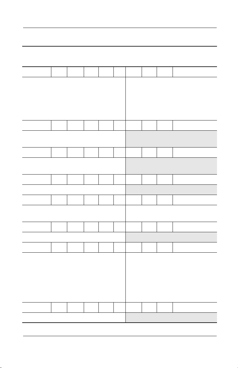
Flowchart 2.1 - Initial Troubleshooting
Begin
troubleshooting.
N
Troubleshooting
Is there
power?
Y
Beeps,
LEDs, or error
messages?
Y
Is there video?
(no boot)
Y
Is the OS
loading?
Y
Is there
sound?
Y
Flowchart 2.2,
No Power, Part 1.
N
LED board,
connections.
N
Flowchart 2.6,
No Video, Part 1.
N
Flowchart 2.9,
No OS Loading.
N
Flowchart 2.15,
Go to
Check
speaker
Go to
Go to
Go to
No Audio.
All drives
working?
Y
Keyboard/
pointing device
working?
Y
Connecting
to network
or modem?
Y
End
N
Flowchart 2.17,
Nonfunctioning
N
Flowchart 2.18,
Nonfunctioning
Keyboard,
or Flowchart 2.19,
Nonfunctioning
Pointing Device.
N
Flowchart 2.20,
No Network or
Connection.
Go to
Device.
Go to
Go to
Modem
Maintenance and Service Guide 2–11
Page 47

Troubleshooting
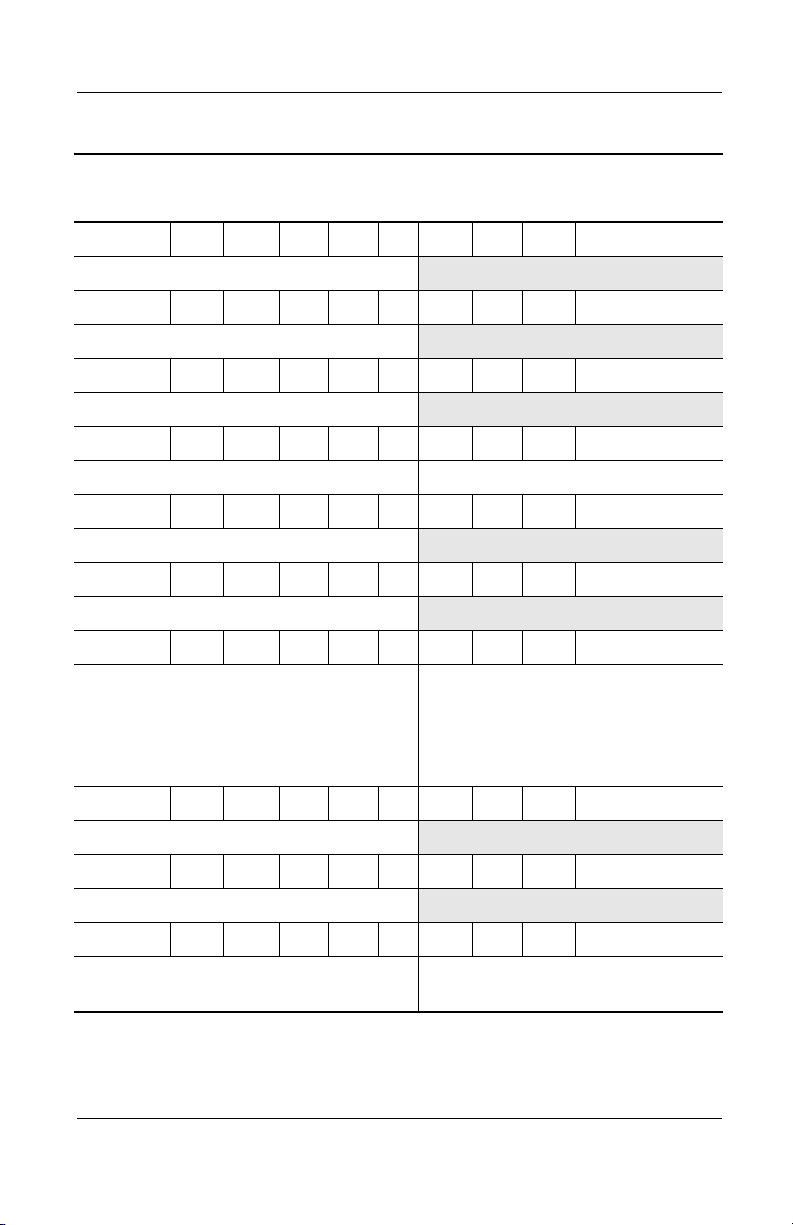
Flowchart 2.2 - No Power, Part 1
No power
(power LED
is off).
Remove from
docking station
(if applicable).
N
Power up
on battery
power?
*Reset
power.
Y
N
Power up
on AC
power?
*Reset
power.
Y
Y
Power up
in docking
station?
Done
N
1. Reseat the power cables in the docking
station and at the AC outlet.
2. Ensure that the AC power source is active.
3. Ensure that the power strip is working.
YN
Done
Power up
in docking
station?
N
Power up
on battery
power?
Go to
Flowchart 2.3,
No Power,
Part 2.
Y
N
Power up
on AC
power?
Go to
Flowchart 2.4,
No Power,
Part 3.
Y
*On some models there is a separate reset
button. On some models the computer may be
reset using the Standby switch and either the
lid switch or the main power switch.
Go to
Flowchart 2.8,
Nonfunctioning
Docking Station.
2–12 Maintenance and Service Guide
Page 48

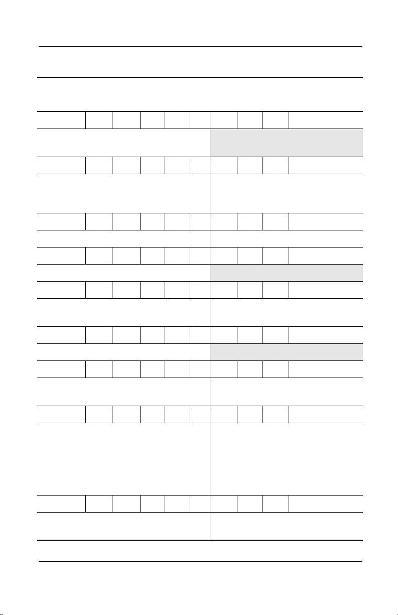
Flowchart 2.3 - No Power, Part 2
Continued from
Flowchart 2.2,
No Power, Part 1.
Visually check for
debris in battery
socket and clean if
necessary.
Y
Troubleshooting
Power on?
N
Check battery
by recharging,
moving it to
another computer,
or replacing it.
Power on?
Y
Done
Done
N
Replace
power supply
(if applicable).
N
Go to
Power on?
Flowchart 2.4,
No Power,
Part 3.
Y
Done
Maintenance and Service Guide 2–13
Page 49

Troubleshooting
Flowchart 2.4 - No Power, Part 3
Continued from
Flowchart 2.3,
No Power, Part 2.
Plug directly
into AC outlet.
Y
Power LED
on?
N
Reseat AC adapter
in computer and
at power source.
Power on?
N
Power outlet
active?
Y
Replace
power cord.
Power on?
Done
Y
Done
N
Try different
outlet.
Internal or
external AC
Internal
Flowchart 2.5,
No Power,
Y
Done
adapter?
Go to
Part 4.
External
Replace external
AC adapter.
N
Power on?
Y
Done
N
2–14 Maintenance and Service Guide
Page 50

Flowchart 2.5 - No Power, Part 4
Continued from
Flowchart 2.4,
No Power, Part 3.
Open
computer.
Troubleshooting
Loose or
damaged
parts?
N
Close
computer and
retest.
Power on?
Y
Done
Y
Reseat loose
components and
boards and
replace
damaged items.
N
Replace the following items (if applicable).
Check computer operation after each
replacement:
1. Internal DC-DC converter*
2. Internal AC adapter
3. Processor board*
4. System board*
*Replace these items as a set to prevent
shorting out among components.
Maintenance and Service Guide 2–15
Page 51

Troubleshooting
Flowchart 2.6 - No Video, Part 1
No video.
Docking
station
Stand-alone
or docking
station?
Go to
Flowchart 2.7,
No Video, Part 2.
*To change from internal to
external display, use the hotkey
combination.
Stand-alone
Y
Internal or
external
display*?
External
Adjust
brightness.
Internal
Y
Video OK? Done
N
Check for bent
pins on cable.
N
Video OK?
Adjust
brightness.
Video OK?
Done
N
A
Press lid
switch to ensure
operation.
Y
Video OK?
Done
N
Replace the following one at a time. Test after each replacement.
1. Cable between notebook and computer display (if applicable)
2. Inverter board (if applicable)
3. Display
4. System board
N
Try
another
display.
Internal and
external
video OK?
Replace
system
board.
YY
Done
2–16 Maintenance and Service Guide
Done
Page 52

Flowchart 2.7 - No Video, Part 2
Continued from
Flowchart 2.6,
No Video, Part 1.
Remove
notebook from
docking station,
if connected.
Troubleshooting
Adjust
display
brightness.
N
Video OK?
No Video, Part 1.
Y
Check that notebook is properly
seated in docking station,
for bent pins on cable,
and for monitor connection.
Y
Video OK?
N
Adjust external
monitor display.
Go to “A” in
Flowchart 2.6,
Done
Check brightness
of external
monitor.
Video OK?
N
Try another
external
monitor.
Internal
and external
video OK?
N
Go to
Flowchart 2.8,
Nonfunctioning
Docking Station.
Y
Done
Y
Done
Maintenance and Service Guide 2–17
Page 53

Troubleshooting
Flowchart 2.8 - Nonfunctioning Docking Station
(if applicable)
Nonfunctioning
docking station.
Reseat power cord
in docking
station and
power outlet.
Check voltage
setting on
docking station.
Reset monitor
cable connector at
docking station.
Docking
station
operating?
N
Remove
notebook, reseat
all internal parts,
and replace any
damaged items in
docking station.
Reinstall
notebook into
docking station.
Y
Docking
station
operating?
Y
Done
N
Replace the following docking station
components one at a time. Check
computer operation after each
replacement.
1. Power supply
2. I/O board
3. Backplane board
4. Switch box
5. Docking motor mechanism
Done
2–18 Maintenance and Service Guide
Page 54

Troubleshooting
Flowchart 2.9 - No Operating System (OS) Loading
No OS
loading.*
Reseat power
cord in docking
station and
power outlet.
*Before beginning troubleshooting, always
check cable connections, cable ends, and
drives for bent or damaged pins.
No OS loading
from hard drive,
go to Flowchart 2.10,
No OS Loading from
Hard Drive, Part 1.
No OS loading
from diskette drive,
go to Flowchart 2.13,
No OS Loading from
Diskette Drive.
No OS loading
from CD- or
DVD-ROM drive,
go to Flowchart 2.14,
No OS Loading
from CD- or
DVD-ROM Drive.
Maintenance and Service Guide 2–19
Page 55

Troubleshooting
Flowchart 2.10 - No OS Loading from Hard Drive, Part 1
OS not
loading from
hard drive.
Nonsystem
disk message?
N
Reseat
external
hard drive.
OS loading?
N
Boot from
CD?
Y
Check the setup
utility for correct
booting order.
Y
Go to
Flowchart 2.11,
No OS Loading
from Hard Drive,
Part 2.
Y
Done
N
N
Boot from
diskette?
Y
Go to
Flowchart 2.13,
No OS
Loading from
Diskette Drive.
N
Boot from
hard drive?
Y
Done
Change boot
priority through
the setup utility
and reboot.
Boot from
hard drive?
N
Go to
Flowchart 2.17,
Nonfunctioning
Device.
Y
2–20 Maintenance and Service Guide
Page 56

Troubleshooting
Flowchart 2.11 - No OS Loading from Hard Drive, Part 2
Continued from
Flowchart 2.10,
No OS Loading
from Hard Drive,
Part 1.
CD or
diskette in
drive?
Y
Remove
diskette and
reboot.
N
1. Replace hard
drive.
2. Replace
system board.
N
Reseat
hard drive.
Hard drive
accessible?
Run FDISK.
Y
Done
Boot from
hard drive?
N
Boot from
diskette drive?
Y
Hard drive
accessible?
Y
Go to
Flowchart 2.12,
No OS Loading
from Hard Drive,
Part 3.
Y
N
N
Done
Go to
Flowchart 2.13,
No OS Loading
from Diskette
Drive.
Done
Hard drive
partitioned?
Y
Hard drive
formatted?
Y
Y
Computer
booted?
Go to
Flowchart 2.12,
No OS Loading
from Hard Drive,
Part 3.
N
Create partition,
then format hard
drive to bootable
C:\ prompt.
N
Format hard drive
and bring to
a bootable
C:\ prompt.
Load OS using
Restore CD
(if applicable).
N
Maintenance and Service Guide 2–21
Page 57

Troubleshooting
Flowchart 2.12 - No OS Loading from Hard Drive, Part 3
Continued from
Flowchart 2.11,
No OS Loading
from Hard Drive,
Part 2.
N
System
files on hard
drive?
Y
Virus
on hard
drive?
N
Run SCANDISK
and check for
bad sectors.
Can bad
sectors
be fixed?
Y
Fix bad
sectors.
Install OS
and reboot.
Y
Clean virus.
OS
loading from
hard drive?
Y
Done
N
Y
Diagnostics
on diskette?
Replace
hard drive.
N
N
Replace
hard drive.
Run diagnostics
and follow
recommendations.
N
Boot from
hard drive?
Replace
hard drive.
Y
Done
2–22 Maintenance and Service Guide
Page 58

Troubleshooting
Y
Flowchart 2.13 - No OS Loading from Diskette Drive
OS not loading
from
diskette drive.
Nonsystem
disk message?
Boot
from another
device?
Y
Diskette
drive enabled
in the setup
utility?
Y
Y
N
N
Reseat
diskette drive.
Go to
Flowchart 2.17,
Nonfunctioning
Device.
Enable drive
and cold boot
computer.
OS
loading?
N
Bootable
diskette
in drive?
YN
Check diskette
for system files.
Try different
diskette.
Nonsystem
disk error?
N
Done
N
Install bootable
diskette and
reboot computer.
Y
1. Replace
diskette drive.
2. Replace
system board.
Y
Diskette
drive boot
order?
N
Change boot
priority using
the setup utility.
Maintenance and Service Guide 2–23
Clear CMOS.
Refer to
Section 1.3,
“Clearing a
Password,” for
instructions.
Go to
Flowchart 2.17,
Nonfunctioning
Device.
N
OS
loading?
Done
Y
Page 59

Troubleshooting
Y
N
Flowchart 2.14 - No OS Loading from CD- or
DVD-ROM Drive
No OS
loading from
CD- or
DVD-ROM Drive.
Boots from
CD or DVD?
N
Reseat
drive.
N
Y
N
Y
Disc
in drive?
Install
bootable disc.
Done
Boots from
CD or DVD?
Booting
from another
device?
Y
Y
N
Bootable
disc in
drive?
Try another
bootable disc.
Done
Go to
Flowchart 2.17,
Nonfunctioning
Device.
Install
bootable disc
and reboot
computer.
Y
Booting
order
correct?
N
Correct boot
order using
the setup utility.
2–24 Maintenance and Service Guide
Clear CMOS.
Refer to
Section 1.3,
“Clearing a
Password,” for
instructions.
Go to
Flowchart 2.17,
Nonfunctioning
Device.
Page 60

Flowchart 2.15 - No Audio, Part 1
Y
Troubleshooting
No audio.
Notebook in
docking station
(if applicable)?
N
Go to
Flowchart 2.16,
No Audio, Part 2.
Y
Turn up audio
internally or
externally.
Undock
Replace the following docking station
components one at a time as applicable.
Check after each change.
1. Reseat docking station audio cable.
2. Replace audio cable.
3. Replace speaker.
4. Replace docking station audio board.
5. Replace backplane board.
6. Replace I/O board.
Go to
Flowchart 2.17,
Nonfunctioning
Device.
Audio?
Done
N
N
Internal
audio?
Go to
Flowchart 2.16,
No Audio, Part 2.
Y
Y
Audio?
Done
N
Maintenance and Service Guide 2–25
Page 61

Troubleshooting
Flowchart 2.16 - No Audio, Part 2
Continued from
Flowchart 2.15,
No Audio, Part 1.
N
Audio
driver in OS
configured?
Reload
audio drivers.
Y
N
Correct
drivers for
application?
Load drivers
and set
configuration
in OS.
Y
Connect to
external
speaker.
Replace audio
board and
Audio?
YN
speaker
connections
in notebook
(if applicable).
1. Replace internal speakers.
2. Replace audio board (if applicable).
3. Replace system board.
Audio?
YN
Done
2–26 Maintenance and Service Guide
Page 62

Flowchart 2.17 - Nonfunctioning Device
Nonfunctioning
device.
Reseat
device.
Unplug the nonfunctioning device
from the notebook and inspect cables
and plugs for bent or broken pins or
other damage.
Y
Troubleshooting
Clear
CMOS.
Any physical
device detected?
Fix or
replace
broken item.
N
Reattach device.
Close notebook,
plug in power,
and reboot.
Possible bad
hard drive.
Replace drive.
Go to
Flowchart 2.9,
No OS Loading.
N
Device
boots
properly?
Y
Done
Maintenance and Service Guide 2–27
Possible bad NIC.
Replace card. If
integrated NIC,
replace system
board.
Possible bad
diskette drive.
Replace drive.
Device
boots
properly?
Y
Done
N
Page 63

Troubleshooting
Flowchart 2.18 - Nonfunctioning Keyboard
Keyboard
not operating
properly.
Connect notebook
to good external
keyboard.
N
External
device
works?
Y
Reseat internal
keyboard
connector
(if applicable).
Replace
system
board.
N
OK?
Replace internal
keyboard or
cable.
Y
Y
Done Done
OK?
N
Replace
system
board.
2–28 Maintenance and Service Guide
Page 64

Troubleshooting
Flowchart 2.19 - Nonfunctioning Pointing Device
Pointing device
not operating
properly.
Connect notebook
to good external
pointing device.
N
External
device
works?
Replace
system
board.
Y
Reseat internal
pointing device
connector
(if applicable).
N
OK?
Replace internal
pointing device
or cable.
Y
Y
Done Done
OK?
N
Replace
system
board.
Maintenance and Service Guide 2–29
Page 65

Troubleshooting
Flowchart 2.20 - No Network or Modem Connection
No network
or modem
connection.
N
Network or
modem jack
active?
Y
Digital
line?
N
NIC/modem
configured
in OS?
Y
Y
N
Replace jack
or have jack
activated.
Connect
to nondigital
line.
Reload
drivers and
reconfigure.
Y
OK?
Done
N
Disconnect all
power from
the notebook
and open.
Reseat
NIC/modem
(if applicable).
Replace
NIC/modem
(if applicable).
OK?
Y
Done
N
Replace
system
board.
2–30 Maintenance and Service Guide
Page 66

Illustrated Parts Catalog
This chapter provides an illustrated parts breakdown and a
reference for spare part numbers and option part numbers.
3.1 Serial Number Location
When ordering parts or requesting information, provide the
computer serial number and model number located on the bottom
of the computer (Figure 3-1).
3
Figure 3-1. Serial Number Location
Maintenance and Service Guide 3–1
Page 67

Illustrated Parts Catalog
3.2 Computer System Major Components
Figure 3-2. Computer System Major Components
3–2 Maintenance and Service Guide
Page 68

Spare Parts: Computer System Major Components
Item Description
1 Displays
for use only with Evo Notebook N1015 models
15.0-inch, TFT, XGA
14.1-inch, TFT, XGA
13.3-inch, TFT, XGA
for use only with Evo Notebook N1005 models
15.0-inch, TFT, SXGA+
15.0-inch, TFT, XGA
14.1-inch, TFT, XGA
for use only with Presario 900 models using 45W
processors (refer to item 11, “Processors,” for a
listing of 45W processors and spare part
numbers)
15.0-inch, TFT, XGA
14.1-inch, TFT, XGA
13.3-inch, TFT, XGA
for use only with Presario 900 models
15.0-inch, TFT, SXGA+
15.0-inch, TFT, XGA
14.1-inch, TFT, XGA
Display Inverter Board Kit (not illustrated)
Illustrated Parts Catalog
Table 3-1
Spare Part
Number
310689-001
311286-001
309645-001
291643-001
291642-001
291641-001
310688-001
310687-001
309644-001
286754-001
285521-001
285520-001
293348-001
Maintenance and Service Guide 3–3
Page 69

Illustrated Parts Catalog
Figure 3-2. Computer System Major Components
3–4 Maintenance and Service Guide
Page 70

Illustrated Parts Catalog
Table 3-1
Spare Parts: Computer System Major Components
Item Description
Miscellaneous Plastics/Hardware Kit, includes: 285541-001
(Continued)
Spare Part
Number
2a
2b
2c
2d
2e
2f
2g
2h
2i
2j
2k
2l
2m
3 LED covers
Left hinge cover
Right hinge cover
*Display release assembly
TouchPad bracket
Charger board shield
Optical drive rear alignment rail
Optical drive front alignment rail
PC Card space saver
*Connector cover
*Hard drive bracket
*Mini PCI compartment cover
*Memory expansion compartment cover
*Battery bezel
*Includes two of each part, one with carbon finish for use with
Evo Notebook N1005 models and one with silver finish for use
with Presario 900 models
Not illustrated: Computer feet
for use only with Evo N1015 models and Presario
900 models using 45W* processors
for use only with Evo N1005 models and Presario
900 models using non-45W* processors
*refer to item 11, “Processors,” for a listing of 45W and non-45W
processors and spare part numbers
310695-001
285536-001
Maintenance and Service Guide 3–5
Page 71

Illustrated Parts Catalog
Figure 3-2. Computer System Major Components
3–6 Maintenance and Service Guide
Page 72

Illustrated Parts Catalog
Table 3-1
Spare Parts: Computer System Major Components
Item Description
4 Keyboards
(Continued)
Spare Part
Number
Arabic
Belgian
Brazilian
Chinese
Czech
Danish
French
French
Canadian
German
Hebrew
Hungarian
International
Italian
Japanese
Miscellaneous Cable Kit, includes: 285540-001
5a
5b
5c
5d
6 Top covers
Diskette drive cable
TouchButton board-to-TouchPad cable
System board-to-TouchButton board cable
Modem cable
for use only with Evo Notebook N1015 models and
Presario 900 models using 45W* processors
for use only with Evo Notebook N1005 models and
Presario 900 models using non-45W* processors
285530-171
285530-181
285530-201
285530-AA1
285530-221
285530-081
285530-051
285530-121
285530-041
285530-BB1
285530-211
285530-002
285530-061
285530-291
Korean
Latin American
Spanish
Norwegian
Portuguese
Russian
Slovakian
Spanish
Swedish
Swiss
Taiwanese
Thai
Tu r ki s h
U.K. English
U.S. English
285530-AD1
285530-161
285530-091
285530-131
285530-251
285530-231
285530-071
285530-101
285530-111
285530-AB1
285530-281
285530-141
285530-031
285530-001
310694-001
285535-001
*refer to item 11, “Processors,” for a listing of 45W and non-45W
processors and spare part numbers
Maintenance and Service Guide 3–7
Page 73

Illustrated Parts Catalog
Figure 3-2. Computer System Major Components
3–8 Maintenance and Service Guide
Page 74

Illustrated Parts Catalog
Table 3-1
Spare Parts: Computer System Major Components
Item Description
7 Palm rests
(Continued)
Spare Part
Number
for use only with Evo Notebook N1015 models
(does not include pointing stick or diskette drive)
for use only with Presario 900 models using 45W
processors* (does not include pointing stick or
diskette drive)
for use only with Presario 900 models using 45W
processors* (includes pointing stick)
for use only with Evo Notebook N1005 models
for use only with Presario 900 models using
non-45W processors*
*refer to item 11, “Processors,” for a listing of 45W processors and
spare part numbers
8 Diskette drive 285539-001
TouchPad components
9a
9b
TouchPad
TouchButton board
All TouchPad components are included with the palm rest. Refer to
item 7, “Palm rests,” for more information.
All TouchPad cables are included in the Miscellaneous Cable Kit.
Refer to item 5, “Miscellaneous Cable Kit,” for more information.
The TouchPad bracket is included in the Miscellaneous Plastics/
Hardware Kit. Refer to item 2, “Miscellaneous Plastics/
Hardware Kit,” for more information.
311955-001
310693-001
310692-001
291645-001
285533-001
Maintenance and Service Guide 3–9
Page 75

Illustrated Parts Catalog
Figure 3-2. Computer System Major Components
3–10 Maintenance and Service Guide
Page 76

Illustrated Parts Catalog
Table 3-1
Spare Parts: Computer System Major Components
Item Description
10 Heat spreaders
(Continued)
Spare Part
Number
for use only with AMD Athlon XP 45W processors*
for use only with AMD Athlon XP non-45W
processors*
for use only with AMD Duron processors
*refer to item 11, “Processors,” for a listing of 45W and non-45W
processors and spare part numbers
11 Processors
The following processors are 45W processors:
AMD Athlon XP 2000+ 1.67-GHz processor
AMD Athlon XP 1900+ 1.60-GHz processor
AMD Athlon XP 1800+ 1.53-GHz processor
AMD Athlon XP 1700+ 1.47-GHz processor
AMD Athlon XP 1600+ 1.40-GHz processor
AMD Athlon XP 1500+ 1.30-GHz processor
AMD Athlon XP 1400+ 1.20-GHz processor
The following processors are non-45W processors:
AMD Athlon XP 1800+ 1.53-GHz processor
AMD Athlon XP 1700+ 1.47-GHz processor
AMD Athlon XP 1600+ 1.40-GHz processor
AMD Athlon XP 1500+ 1.30-GHz processor
AMD Athlon XP 1400+ 1.20-GHz processor
AMD Duron 1.30-GHz processor
12 Charger board 285525-001
13 Speaker assembly 285538-001
309646-001
291594-001
291595-001
309643-001
309642-001
309641-001
309640-001
309639-001
312535-001
312986-001
301644-001
291592-001
291591-001
291590-001
293664-001
291589-001
14 Fan 285543-001
Maintenance and Service Guide 3–11
Page 77

Illustrated Parts Catalog
Figure 3-2. Computer System Major Components
3–12 Maintenance and Service Guide
Page 78

Illustrated Parts Catalog
Table 3-1
Spare Parts: Computer System Major Components
Item Description
15 System boards (do not contain memory)
(Continued)
Spare Part
Number
for use only with notebook models using 45W
processors*
for use only with notebook models using non-45W
processors*
*refer to item 11, “Processors,” for a listing of 45W and non-45W
processors and spare part numbers
16 Base enclosures (include shields)
for use only with Evo Notebook N1015 models
for use only with Evo Notebook N1005 models
for use only with Presario 900 models using
45W* processors
for use only with Presario 900 models using
non-45W* processors
*refer to item 11, “Processors,” for a listing of 45W and non-45W
processors and spare part numbers
17 Hard drives
40 GB
30 GB
20 GB
18 Mini PCI communications boards
U.S. modem
International modem
309638-001
291588-001
311624-001
295718-001
310691-001
291593-001
273491-001
192406-001
288291-001
248776-001
248777-002
and
285545-001
Maintenance and Service Guide 3–13
Page 79

Illustrated Parts Catalog
Figure 3-2. Computer System Major Components
3–14 Maintenance and Service Guide
Page 80

Illustrated Parts Catalog
Table 3-1
Spare Parts: Computer System Major Components
Item Description
19 Disk cell RTC battery, 3 volt, 36 MAh, Li ion 279769-001
20 Memory expansion boards
512 MB
256 MB
128 MB
21 Battery packs
8 cell, 62 Wh, 3.6 Ah, Li ion
8 cell, 58 Wh, 3.6 Ah, Li ion
22 Optical drive
24X Max CD-ROM/CD-RW combination drive
24X Max CD-ROM drive
16X Max CD-RW drive
8X Max DVD-ROM drive
8X Max DVD-ROM drive
8X Max DVD-ROM/CD-RW combination drive
8X Max DVD-ROM/CD-RW combination drive
(Continued)
Spare Part
Number
285524-001
285523-001
285522-001
289053-001
281766-001
310690-001
285526-001
and
311954-001
285528-001
311280-001
285527-001
311281-001
285529-001
Maintenance and Service Guide 3–15
Page 81

Illustrated Parts Catalog
3.3 Miscellaneous Plastics/Hardware Kit
Figure 3-3. Miscellaneous Plastics/Hardware
Kit Components
3–16 Maintenance and Service Guide
Page 82

Illustrated Parts Catalog
Table 3-2
Miscellaneous Plastics/Hardware Kit Components
Spare Part Number 285541-001
Item Description Item Description
1 Left hinge cover 8 PC Card space saver
2 Right hinge cover 9 *Connector cover
3 *Display release assembly 10 *Hard drive bracket
4 TouchPad bracket 11 *Mini PCI compartment cover
5 Charger board shield 12 *Memory expansion
compartment cover
6 Optical drive rear
alignment rail
7 Optical drive front
alignment rail
*Includes two of each part, one with carbon finish for use with Evo Notebook
N1005 models and one with silver finish for use with Presario 900 models
13 *Battery bezel
14 Computer feet
Maintenance and Service Guide 3–17
Page 83

Illustrated Parts Catalog
3.4 Miscellaneous Cable Kit
Figure 3-4. Miscellaneous Cable Kit Components
Table 3-3
Miscellaneous Cable Kit Components
Spare Part Number 285540-001
Item Description
1 Diskette drive cable
2 TouchButton board-to-TouchPad cable
3 System board-to-TouchButton board cable
4 Modem cable
3–18 Maintenance and Service Guide
Page 84

3.5 Mass Storage Devices
Illustrated Parts Catalog
l
Table 3-4
Mass Storage Devices
Spare Part
Figure 3-5. Mass Storage Devices
Item Description
1 Hard drives
40 GB
30 GB
20 GB
2 Diskette drive 285539-001
3 Optical drives
24X Max CD-ROM/CD-RW combination drive
24X Max CD-ROM drive
16X Max CD-RW drive
8X Max DVD-ROM drive
8X Max DVD-ROM drive
8X Max DVD-ROM/CD-RW combination drive
8X Max DVD-ROM/CD-RW combination drive
Number
273491-001
192406-001
288291-001
310690-001
285526-001
and
311954-001
285528-001
311280-001
285527-001
311281-001
285529-001
Maintenance and Service Guide 3–19
Page 85

Illustrated Parts Catalog
3.6 Miscellaneous
Tabl e 3 - 5
Spare Parts: Miscellaneous (not illustrated)
Spare Part
Description
Logo Kit 285547-001
Screw Kit, includes the following screws (Refer to Appendix C,
“Screw Listing,” for more information on screw specifications
and usage.)
Number
285542-001
■ Torx T8 Metric 2.5 × 5.0
■ Torx T8 Metric 2.5 × 8.0
■ Torx T8 Metric 2.5 × 9.0
■ Torx T8 Metric 2.5 × 14.0
shoulder screw
AC adapter, 90 W, 3 wire, slim line 286755-001
Power cords, 3 wire
Australian
Danish
International
Italian
170513-011
170513-081
170513-002
170513-061
■ Phillips Metric 3.0 × 3.0
■ Phillips Metric 2.5 × 4.0
■ Phillips Metric 2.0 × 4.5
Korean
Swiss
U.K. English
U.S. English
170513-AD1
170513-115
170513-031
170513-001
3–20 Maintenance and Service Guide
Page 86

Removal and Replacement
This chapter provides essential information for proper and safe
removal and replacement service.
4.1 Tools Required
You will need the following tools to complete the removal and
replacement procedures:
■ Magnetic screwdriver
■ Phillips P0 screwdriver
■ Torx T8 screwdriver
■ Tool kit (includes connector removal tool, loopback plugs,
and case utility tool)
4
Preliminaries
Maintenance and Service Guide 4–1
Page 87

Removal and Replacement Preliminaries
4.2 Service Considerations
The following sections include some of the considerations that
you should keep in mind during disassembly and assembly
procedures.
As you remove each subassembly from the computer, place the
✎
subassembly (and all accompanying screws) away from the work
area to prevent damage.
Plastic Parts
Using excessive force during disassembly and reassembly can
damage plastic parts. Use care when handling the plastic parts.
Apply pressure only at the points designated in the maintenance
instructions.
Cables and Connectors
Cables must be handled with extreme care to avoid damage.
Apply only the tension required to unseat or seat the cables
during removal and insertion. Handle cables by the connector
whenever possible. In all cases, avoid bending, twisting, or
tearing cables. Ensure that cables are routed in such a way that
they cannot be caught or snagged by parts being removed or
replaced. Handle flex cables with extreme care; these cables tear
easily.
CAUTION: When servicing the computer, ensure that cables are
Ä
placed in their proper locations during the reassembly process.
Improper cable placement can damage the computer.
4–2 Maintenance and Service Guide
Page 88

Removal and Replacement Preliminaries
4.3 Preventing Damage to Removable Drives
Removable drives are fragile components that must be handled
with care. To prevent damage to the computer, damage to a
removable drive, or loss of information, observe the following
precautions:
■ Before removing or inserting a hard drive, shut down the
computer. If you are unsure whether the computer is off or in
Hibernation, turn the computer on, then shut it down.
■ Before removing a diskette drive or optical drive, ensure that
a diskette or disc is not in the drive. Ensure that the optical
drive tray is closed.
■ Before handling a drive, ensure that you are discharged of
static electricity. While handling a drive, avoid touching the
connector.
■ Handle drives on surfaces that have at least one inch of
shock-proof foam.
■ Avoid dropping drives from any height onto any surface.
■ After removing a hard drive, CD-ROM drive, or a diskette
drive, place it in a static-proof bag.
■ Avoid exposing a hard drive to products that have magnetic
fields, such as monitors or speakers.
■ Avoid exposing a drive to temperature extremes or to liquids.
■ If a drive must be mailed, place the drive in a bubble-pack
mailer or other suitable form of protective packaging and
label the package “Fragile: Handle With Care.”
Maintenance and Service Guide 4–3
Page 89

Removal and Replacement Preliminaries
4.4 Preventing Electrostatic Damage
Many electronic components are sensitive to electrostatic
discharge (ESD). Circuitry design and structure determine the
degree of sensitivity. Networks built into many integrated circuits
provide some protection, but in many cases the discharge contains
enough power to alter device parameters or melt silicon junctions.
A sudden discharge of static electricity from a finger or other
conductor can destroy static-sensitive devices or microcircuitry.
Often the spark is neither felt nor heard, but damage occurs.
An electronic device exposed to electrostatic discharge may not
be affected at all and can work perfectly throughout a normal
cycle. Or the device may function normally for a while, then
degrade in the internal layers, reducing its life expectancy.
4.5 Packaging and Transporting Precautions
Use the following grounding precautions when packaging and
transporting equipment:
■ To avoid hand contact, transport products in static-safe
containers, such as tubes, bags, or boxes.
■ Protect all electrostatic-sensitive parts and assemblies with
conductive or approved containers or packaging.
■ Keep electrostatic-sensitive parts in their containers until the
parts arrive at static-free workstations.
■ Place items on a grounded surface before removing items
from their containers.
■ Always be properly grounded when touching a sensitive
component or assembly.
4–4 Maintenance and Service Guide
Page 90

Removal and Replacement Preliminaries
■ Store reusable electrostatic-sensitive parts from assemblies in
protective packaging or nonconductive foam.
■ Use transporters and conveyers made of antistatic belts and
roller bushings. Ensure that mechanized equipment used for
moving materials is wired to ground and that proper materials
are selected to avoid static charging. When grounding is not
possible, use an ionizer to dissipate electric charges.
4.6 Workstation Precautions
Use the following grounding precautions at workstations:
■ Cover the workstation with approved static-dissipative
material (refer to Table 4-2).
■ Use a wrist strap connected to a properly grounded work
surface and use properly grounded tools and equipment.
■ Use conductive field service tools, such as cutters,
screwdrivers, and vacuums.
■ When using fixtures that must directly contact dissipative
surfaces, only use fixtures made of static-safe materials.
■ Keep the work area free of nonconductive materials, such as
ordinary plastic assembly aids and Styrofoam.
■ Handle electrostatic-sensitive components, parts, and
assemblies by the case or PCM laminate. Handle these items
only at static-free workstations.
■ Avoid contact with pins, leads, or circuitry.
■ Turn off power and input signals before inserting or removing
connectors or test equipment.
Maintenance and Service Guide 4–5
Page 91

Removal and Replacement Preliminaries
4.7 Grounding Equipment and Methods
Grounding equipment must include either a wrist strap or a foot
strap at a grounded workstation.
■ When seated, wear a wrist strap connected to a grounded
system. Wrist straps are flexible straps with a minimum of
one megohm ±10% resistance in the ground cords. To
provide proper ground, wear a strap snugly against the skin
at all times. On grounded mats with banana-plug connectors,
connect a wrist strap with alligator clips.
■ When standing, use foot straps and a grounded floor mat.
Foot straps (heel, toe, or boot straps) can be used at standing
workstations and are compatible with most types of shoes
or boots. On conductive floors or dissipative floor mats, use
foot straps on both feet with a minimum of one-megohm
resistance between the operator and ground. To be effective,
the conductive strips must be worn in contact with the skin.
Other grounding equipment recommended for use in preventing
electrostatic damage includes:
■ Antistatic tape
■ Antistatic smocks, aprons, and sleeve protectors
■ Conductive bins and other assembly or soldering aids
■ Nonconductive foam
■ Conductive tabletop workstations with ground cords of
one-megohm resistance
■ Static-dissipative tables or floor mats with hard ties to
the ground
■ Field service kits
■ Static awareness labels
■ Material-handling packages
4–6 Maintenance and Service Guide
Page 92

Removal and Replacement Preliminaries
■ Nonconductive plastic bags, tubes, or boxes
■ Metal tote boxes
■ Electrostatic voltage levels and protective materials
Table 4-1 shows how humidity affects the electrostatic voltage
levels generated by different activities.
Table 4-1
Typical Electrostatic Voltage Levels
Relative Humidity
Event 10% 40% 55%
Walking across carpet 35,000 V 15,000 V 7,500 V
Walking across vinyl floor 12,000 V 5,000 V 3,000 V
Motions of bench worker 6,000 V 800 V 400 V
Removing DIPS from plastic tube 2,000 V 700 V 400 V
Removing DIPS from vinyl tray 11,500 V 4,000 V 2,000 V
Removing DIPS from Styrofoam 14,500 V 5,000 V 3,500 V
Removing bubble pack from PCB 26,500 V 20,000 V 7,000 V
Packing PCBs in foam-lined box 21,000 V 11,000 V 5,000 V
A product can be degraded by as little as 700 V.
✎
Table 4-2 lists the shielding protection provided by antistatic bags
and floor mats.
Table 4-2
Static-Shielding Materials
Material Use Voltage Protection Level
Antistatic plastic Bags 1,500 V
Carbon-loaded plastic Floor mats 7,500 V
Metallized laminate Floor mats 5,000 V
Maintenance and Service Guide 4–7
Page 93

5
Removal and Replacement
Procedures
This chapter provides removal and replacement procedures.
There are 57 screws, in seven different sizes, that must be
removed and replaced when servicing the computer. Make
special note of each screw size and location during removal and
replacement.
Refer to Appendix C, “Screw Listing,” for detailed information
on screw sizes, locations, and usage.
Maintenance and Service Guide 5–1
Page 94

Removal and Replacement Procedures
5.1 Serial Number
Report the computer serial number to Compaq when requesting
information or ordering spare parts. The serial number is located
on the bottom of the computer as indicated in Figure 5-1.
Figure 5-1. Serial Number Location
5–2 Maintenance and Service Guide
Page 95

Removal and Replacement Procedures
5.2 Disassembly Sequence Chart
Use the following chart to determine the section number to be
referenced when removing computer components.
Disassembly Sequence Chart
Section Description # of Screws Removed
5.3 Preparing the computer for
disassembly
Battery pack 0
Optical drive 2
Hard drive 1 to remove the hard
5.4 Computer feet 0
5.5 Memory expansion board 1
5.6 Mini PCI communications board 1
5.7 Disk cell RTC battery 0
5.8 Connector cover 2
5.9 LED cover 2
5.10 Keyboard 0
5.11 Heat spreader 7
5.12 Processor 0
drive
4 to remove the hard
drive from hard drive
bracket
Maintenance and Service Guide 5–3
Page 96

Removal and Replacement Procedures
Disassembly Sequence Chart
Section Description # of Screws Removed
5.13 Display 6
5.14 Palm rest 6
5.15 Diskette drive 3
5.16 TouchPad components 4
5.17 Display release assembly 2
5.18 Charger board 3
5.19 Speaker assembly 0
5.20 Top cover 5
5.21 Fan 0
5.22 System board 7
5.23 Modem cable 1
(Continued)
5.3 Preparing the Computer for Disassembly
Perform the following steps before disassembling the computer:
1. Turn off the computer.
2. Disconnect the AC adapter and all external devices.
5–4 Maintenance and Service Guide
Page 97

Removal and Replacement Procedures
Battery Packs
Spare Part Number Information
8 cell, 62 Wh, 3.6 Ah, Li ion
8 cell, 58 Wh, 3.6 Ah, Li ion
3. Remove the battery pack by following these steps:
a. Turn the computer bottom side up with the left side
facing forward.
b. Slide and hold the battery release latch
of the computer (Figure 5-2).
c. Use the notch in the battery bay to slide the battery pack
out of the battery bay
d. Remove the battery pack.
289053-001
281766-001
1 toward the back
2.
Figure 5-2. Releasing the Battery Pack
Reverse the preceding procedures to install the battery pack.
Maintenance and Service Guide 5–5
Page 98

Removal and Replacement Procedures
4. To remove the battery bezel, slide the bezel straight down
(Figure 5-3).
Figure 5-3. Removing the Battery Bezel
Battery bezels are available with carbon finish for Evo Notebook
✎
N1005 models and silver finish for Presario 900 models, and are
included in the Miscellaneous Plastics/Hardware Kit, spare part
number 285541-001.
Reverse the preceding procedures to install the battery bezel.
5–6 Maintenance and Service Guide
Page 99

Removal and Replacement Procedures
Optical Drives
Spare Part Number Information
24X Max CD-ROM/CD-RW combination drive
24X Max CD-ROM drive
16X Max CD-RW drive
8X Max DVD-ROM drive
8X Max DVD-ROM drive
8X Max DVD-ROM/CD-RW combination drive
8X Max DVD-ROM/CD-RW combination drive
5. Remove the optical drive by following these steps:
a. Turn the computer bottom side up with the left side
facing forward.
b. Remove the two TM2.5 × 5.0 screws that secure the
optical drive to the base enclosure (Figure 5-4).
310690-001
285526-001
and
311954-001
285528-001
311280-001
285527-001
311281-001
285529-001
Figure 5-4. Removing the Optical Drive Screws
Maintenance and Service Guide 5–7
Page 100

Removal and Replacement Procedures
c. Turn the computer top side up with the right side facing
forward.
d. Insert a paper clip or similar thin metal rod into the
manual release hole on the front bezel of the optical
1 (Figure 5-5). Press firmly.
drive
e. Grasp the drive bezel and slide the drive out of the optical
drive bay
2.
Figure 5-5. Removing an Optical Drive
Reverse the preceding procedures to install a optical drive.
5–8 Maintenance and Service Guide
 Loading...