

Page 1

b
Hardware Reference Guide
Evo D500 Ultra-Slim Desktop
Document Part Number: 250853-001
November 2001
This book provides more detailed information on the features and use
of the Compaq Evo D500 Ultra-Slim Desktop personal computer, and
includes instructions for removing and replacing internal
components.
Page 2

© 2001 Compaq Computer Corporation.
Compaq, the Compaq logo, and Evo are trademarks of Compaq Information
Technologies Group, L.P. in the U.S. and other countries.
Microsoft, MS-DOS, Windows, Windows NT are trademarks of Microsoft
Corporation in the U.S. and other countries.
All other product names mentioned herein may be trademarks of their respective
companies.
Compaq shall not be liable for technical or editorial errors or omissions
contained herein. The information in this document is provided “as is” without
warranty of any kind and is subject to change without notice. The warranties for
Compaq products are set forth in the express limited warranty statements
accompanying such products. Nothing herein should be construed as
constituting an additional warranty.
WARNING: Text set off in this manner indicates that failure to follow
Å
directions could result in bodily harm or loss of life.
CAUTION: Text set off in this manner indicates that failure to follow
Ä
directions could result in damage to equipment or loss of information.
Printed in the U.S.A.
Hardware Reference Guide
First Edition (November 2001)
Document Part Number: 250853-001
Page 3

Contents
1 Working with the Keyboard and Mouse
Compaq Easy Access Keyboard 1–1
Programming the Easy Access Buttons 1–1
Windows Logo Key 1–2
Special Mouse Functions 1–2
2 Working with the MultiBay
“Hot-Plugging” or “Hot-Swapping” MultiBay Drives 2–2
Partitioning and Formatting a MultiBay Hard Drive 2–3
Windows 2000 Professional or Windows XP Professional 2–3
Uninstalling the MultiBay Security Screw 2–4
Inserting a Drive into the MultiBay 2–5
Removing a Drive from the MultiBay 2–6
3 Adding System Memory and
Upgrading the Internal Hard Drive
General Precautions 3–1
Removing and Replacing the Access Panel 3–1
Adding System Memory 3–3
Adding or Removing a Memory Module 3–4
Upgrading the Primary Hard Drive 3–7
4 Using the Legacy Module
Removing the Rear Panel Cover 4–2
Connecting the Legacy Module 4–3
Removing the Legacy Module 4–4
5 Using the MultiPort
What is a Wireless LAN? 5–1
What is the Compaq Evo MultiPort? 5–1
Installing and Using a MultiPort Module 5–1
Hardware Reference Guide iii
Page 4

A Specifications
B Battery Replacement
C Electrostatic Discharge
Preventing Electrostatic Damage C–1
Grounding Methods C–1
D Routine Care & Shipping Information
Routine Care D–1
CD-ROM Drive Precautions D–2
Operation D–2
Cleaning D–2
Safety D–2
Shipping Preparation D–2
Index
Hardware Reference Guide iv
Page 5

Working with the Keyboard and Mouse
Compaq Easy Access Keyboard
In addition to the standard keyboard keys, the Compaq Easy Access
Keyboard offers eight Easy Access Buttons that make accessing your
favorite Web sites, services, and applications easier and faster.
Programming the Easy Access Buttons
All Easy Access Buttons can be reprogrammed to open any software
application or data file on your hard drive, or any Internet address.
An Internet address, also referred to as a Uniform Resource Locator
(URL), is simply a pointer to a Web page, file, image, newsgroup, or
other resource available on the Internet. It is very similar to the path
and file name used to point to a file on the Personal Computer’s hard
drive. For example, the URL that points to the Compaq Web site is
http://www.compaq.com.
To reprogram your Easy Access Buttons, complete the following
steps:
1
1. Double-click the keyboard icon located in the status area (lower
right corner) of the Windows taskbar.
The Keyboard Properties dialog is displayed.
2. Click the Help button for instructions.
Hardware Reference Guide 1–1
Page 6

Working with the Keyboard and Mouse
Windows Logo Key
Use the Windows Logo Key in combination with other keys to
perform certain functions available in the Windows operating
systems.
Windows Logo Key + F1 Displays a pop-up menu for the selected
object
Windows Logo Key +
Windows Logo Key +
Windows Logo Key +
Windows Logo Key +
Windows Logo Key +
Shift + Windows Logo Key + m Undoes Minimize All
Windows Logo Key +
Ta b Activates the next Taskbar button
e Launches Explore My Computer
f Launches Find Document
Ctrl + f Launches Find Computer
m Minimizes all open applications
r Displays the Run dialog box
Special Mouse Functions
Most software applications support the use of a mouse. Some
software applications assign special functions to each mouse button.
To assign different functions to the mouse buttons, complete the
following steps:
1. Double-click the Mouse icon located in the status area (lower
right corner) of the Windows taskbar.
The Mouse Properties dialog is displayed.
2. Click the Help button for instructions.
1–2 Hardware Reference Guide
Page 7

Working with the MultiBay
The MultiBay is located on the left side of the Evo D500 Ultra-Slim
Desktop personal computer. It is a special drive bay that supports a
variety of optional 12.7-mm removable drives, including:
■ MultiBay 24X Max CD-ROM Drive
■ MultiBay 8X DVD-ROM Drive with Software MPEG-2
■ MultiBay SuperDisk LS-240 Drive
■ MultiBay 1.44-MB Diskette Drive
■ MultiBay CD-RW Drive
■ MultiBay SMART Hard Drive
CAUTION: To prevent loss of work and damage to the personal computer or
a drive:
Ä
■ If you are inserting or removing a hard drive, exit all software
applications, shut down the operating system software, and turn off
the personal computer. Do not remove a hard drive while the
personal computer is on or in standby mode.
■ Before handling a drive, ensure that you are discharged of static
electricity. While handling a drive, avoid touching the connector.
■ Before traveling with, shipping, storing, or removing a drive other
than a hard drive, make sure that no media, such as a diskette,
CD-ROM, or DVD-ROM, is in the drive and that the media tray is
closed.
■ Handle a drive carefully; do not drop it.
■ Do not use excessive force when inserting a drive.
■ Avoid exposing a hard drive to liquids, temperature extremes, or
products that have magnetic fields such as monitors or speakers.
■ If a drive must be mailed, place the drive in a bubble-pack mailer or
other suitable protective packaging and label the package “Fragile:
Handle with Care.”
2
Hardware Reference Guide 2–1
Page 8

Working with the MultiBay
“Hot-Plugging” or “Hot-Swapping” MultiBay Drives
CAUTION: To prevent damage to the personal computer, the drive, and any
data stored on the drive:
Ä
■ If you are inserting or removing a hard drive, shut down the personal
computer. Never remove a hard drive while the personal computer is
on or in Standby. To ensure that the personal computer is not in
Standby, turn the personal computer on, then shut it down.
■ If the personal computer is running a retail version of Windows 98 or
Windows NT 4.0 without software enhancements from Compaq,
shut down the Internet Device before inserting or removing any
drive.
If the personal computer is running a preinstalled operating system
supplied by Compaq, you can insert or remove any drive except a
hard drive while the personal computer is on, off, or in Standby.
2–2 Hardware Reference Guide
Page 9

Working with the MultiBay
Partitioning and Formatting a MultiBay Hard Drive
1. Exit all software applications, shut down the operating system
software, and turn off the personal computer.
2. Insert the hard drive into the MultiBay as shown in “Inserting a
Drive into the MultiBay” on page 2-5.
3. Turn on the personal computer. Follow directions for your
operating system, below:
Windows 2000 Professional or Windows XP Professional
1. Right-click the My Computer icon, then click Manage > Disk
Management.
2. Select the MultiBay hard drive.
3. On the Partition menu, click Create. Carefully read and respond
to any prompts that appear on the screen.
Refer to the Microsoft Management Console online Help (click
Action > Help, while running Management Console) for additional
information.
Hardware Reference Guide 2–3
Page 10
Working with the MultiBay
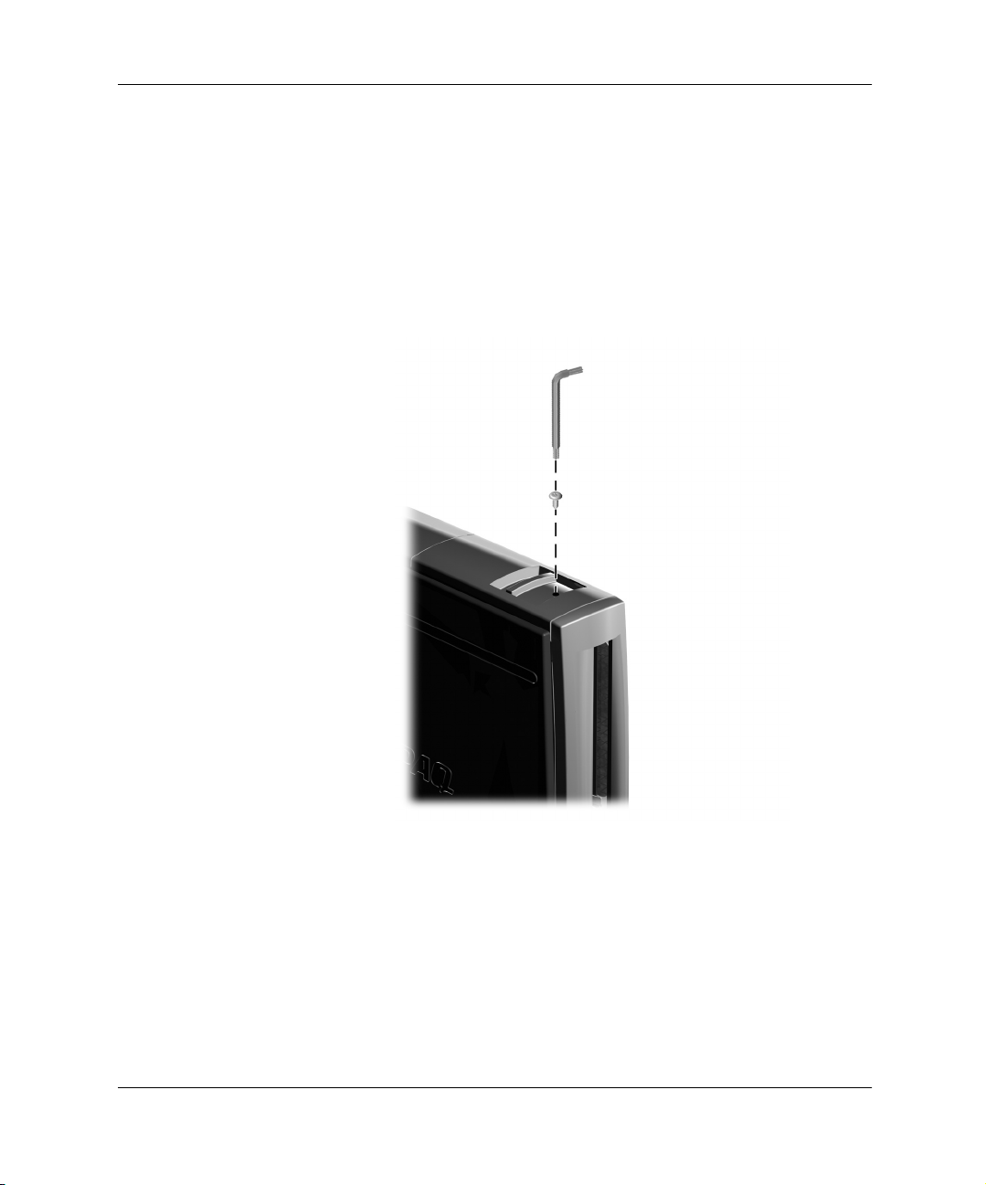
Uninstalling the MultiBay Security Screw
When installed, the MultiBay security screw disables the MultiBay
eject lever, so that a drive installed in the MultiBay cannot be
removed.
To remove a drive installed in the MultiBay, you must first remove the
security screw, if installed, using the special Torx screwdriver
(provided).
Uninstalling the MultiBay Security Screw
2–4 Hardware Reference Guide
Page 11

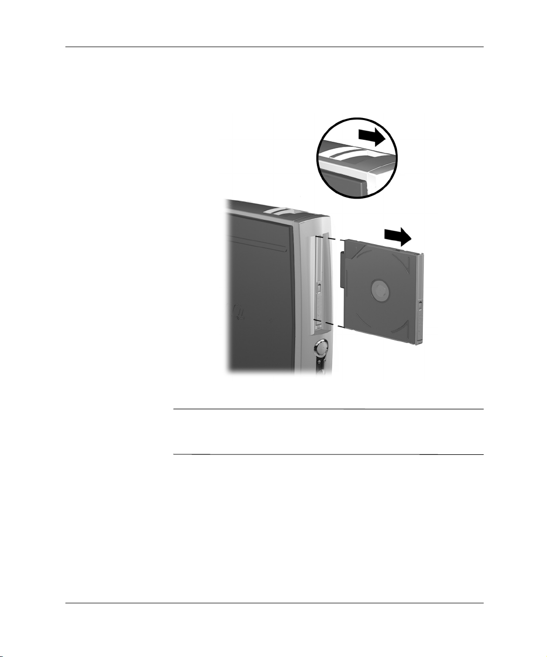
Inserting a Drive into the MultiBay
If the personal computer did not ship with a MultiBay drive, there will
✎
be a drive blank in the MultiBay. Refer to “Removing a Drive from
the MultiBay” on page 2-6 for instructions on removing the drive
blank.
1. Exit all software applications, shut down the operating system
software, and turn off the personal computer if you are inserting
or removing a hard drive.
2. Remove any removable media, such as a compact disc, from the
drive.
3. With the top of the drive facing up (or left, when the personal
computer is in the minitower position) and the drive connector
facing the personal computer, slide the drive into the MultiBay
and push firmly to ensure that the electrical connector is properly
seated.
Working with the MultiBay
Hardware Reference Guide 2–5
Page 12
Working with the MultiBay
Inserting a Drive into the MultiBay
If the device does not start, ensure that the necessary device drivers
are installed on the system. If they are not available, they may be
downloaded, at no cost, from the Compaq Web site at
www.compaq.com.
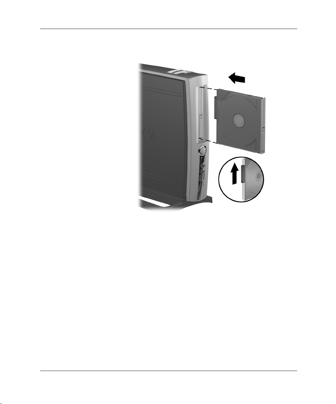
Removing a Drive from the MultiBay
1. Exit all software applications, shut down the operating system
software, and turn off the personal computer if you are inserting
or removing a hard drive.
2. Remove the MultiBay security screw, if it has been installed.
Refer to “Uninstalling the MultiBay Security Screw” on
page 2-4.
2–6 Hardware Reference Guide
Page 13
Working with the MultiBay
3. Pull the eject lever towards the front of the personal computer to
eject the drive from the MultiBay.
Removing a Drive from the MultiBay
If the personal computer did not ship with a drive in the MultiBay,
✎
there will be a drive blank in the MultiBay. Follow the above
procedure to remove it before inserting a MultiBay drive.
Hardware Reference Guide 2–7
Page 14

Working with the MultiBay
2–8 Hardware Reference Guide
Page 15

Adding System Memory and
Upgrading the Internal Hard Drive
General Precautions
Before adding system memory or upgrading the hard drive be sure to
carefully read all of the applicable instructions, cautions, and
warnings in this guide.
WARNING: To reduce the risk of personal injury from electrical shock
Å
and/or hot surfaces, be sure to disconnect the power cord from the wall
outlet, and allow the internal system components to cool before
touching.
CAUTION: Static electricity can damage the electronic components of
Ä
the personal computer or optional equipment. Before beginning these
procedures, ensure that you are discharged of static electricity by briefly
touching a grounded metal object. Refer to Appendix C, “Electrostatic
Discharge” for more information.
3
Removing and Replacing the Access Panel
To access system memory or the internal hard drive, you must remove
the access panel as shown below:
1. Exit all software applications, shut down the operating system
software, turn off the personal computer and any external devices,
then disconnect the power cord from the power outlet.
Hardware Reference Guide 3–1
Page 16

Adding System Memory and Upgrading the Internal Hard Drive
An optional cable lock may be used to secure the access panel,
✎
preventing removal of the interior components, the rear panel cover or
the Legacy Module (if installed). It may also be used to secure the
personal computer to a fixed object.
2. Remove the optional cable lock, if installed.
3. Loosen the two thumbscrews on the rear of the personal
computer, then lift off the access panel.
3–2 Hardware Reference Guide
Page 17

Adding System Memory and Upgrading the Internal Hard Drive
Removing the Access Panel
4. To replace the access panel, ensure that it is aligned properly, then
slide it toward the front of the personal computer and tighten the
two thumbscrews to secure it.
5. Install the optional cable lock, if desired.
Adding System Memory
The memory sockets on the personal computer can be populated with
industry-standard DIMMs. These memory module slots are populated
with at least one preinstalled memory module. To achieve the
maximum memory support, you may be required to replace the
preinstalled DIMM with a higher capacity DIMM.
Hardware Reference Guide 3–3
Page 18

Adding System Memory and Upgrading the Internal Hard Drive
For proper system operation, the DIMMs must be industry-standard
168-pin, 100 MHz, unbuffered, PC100-compliant SDRAM DIMMs,
or 133 MHz, unbuffered, PC133-compliant SDRAM DIMMs. If two
DIMMs are installed, they must be the same speed. This computer
comes equipped with 133 MHz DIMMs.
The SDRAM DIMMs must support CAS Latency 2 or 3 (CL = 2 or
CL = 3). They must also contain the mandatory Joint Electronic
Device Engineering Council (JEDEC) Serial Presence Detect (SPD)
information. DIMMs constructed with x4 SDRAM are not supported;
the system will not start when equipped with unsupported DIMMs.
Adding or Removing a Memory Module
CAUTION: Your memory module sockets have gold-plated metal
Ä
contacts. When upgrading your memory, it is important to use memory
modules with gold-plated metal contacts to prevent corrosion and/or
oxidation resulting from having incompatible metals in contact with each
other.
CAUTION: Static electricity can damage the electronic components of
Ä
the personal computer. Before beginning these procedures, ensure that
you are discharged of static electricity by briefly touching a grounded
metal object. Refer to Appendix C, “Electrostatic Discharge” for more
information.
CAUTION: When handling a memory module, be careful not to touch
any of the contacts. Doing so may damage the module.
1. Exit all software applications, shut down the operating system
software, turn off the personal computer and any external devices,
then disconnect the power cord from the power outlet.
2. Remove the access panel. Refer to “Removing and Replacing the
Access Panel” on page 3-1.
3–4 Hardware Reference Guide
Page 19

Adding System Memory and Upgrading the Internal Hard Drive
Locating the DIMM Slots
WARNING: To reduce the risk of personal injury from hot surfaces,
Å
allow the internal system components to cool before touching.
3. To remove a module, press out on both latches 1 of the DIMM
socket at the same time. This releases the module and partially
pushes it out of the socket.
4. Lift the module from the socket.
Hardware Reference Guide 3–5
Page 20

Adding System Memory and Upgrading the Internal Hard Drive
Adding or Removing Memory Modules
5. To install a memory module, press out on both latches 1 of the
DIMM socket at the same time. Match the notch on the module
with the tab on the memory socket. Firmly push the module
straight into the socket 2, ensuring that the module is fully
inserted and properly seated. The latches will close automatically
when the module is seated correctly, securing the module in the
slot 3.
If only one memory module is used in the system, it must be installed
✎
in the same socket that held the preinstalled memory module.
6. Replace the access panel.
When the personal computer starts up, it will recognize the system
✎
memory upgrade and automatically reconfigure the system.
3–6 Hardware Reference Guide
Page 21

Adding System Memory and Upgrading the Internal Hard Drive
Upgrading the Primary Hard Drive
The primary hard drive is a 3.5-inch hard drive located on the right
side of the personal computer, over the MultiBay.
1. Exit all software applications, shut down the operating system
software, turn off the personal computer and any external devices,
then disconnect the power cord from the power outlet.
2. Remove the access panel. Refer to “Removing and Replacing the
Access Panel” on page 3-1.
Removing the Internal Hard Drive
3. Gently pull the release lever away from the hard drive.
4. Slide the drive toward the power supply, then lift the drive up and
out of the personal computer.
Hardware Reference Guide 3–7
Page 22

Adding System Memory and Upgrading the Internal Hard Drive
5. Disconnect the flat ribbon data cable 1 from the hard drive by
pulling up on the green tab on the cable end.
6. Disconnect the power cable 2 from the hard drive by pulling up
on the connector.
When removing cables, pull on the tab or connector instead of the
✎
cable itself. This will help prevent cable damage.
7. Transfer the four screws from the old drive to the new one. The
screws take the place of drive rails.
8. Connect the flat ribbon data cable 1 and power cable 2 to the
new hard drive.
9. Gently slide the hard drive into the drive cage until the release
lever catches and secures it.
10. Replace the access panel.
3–8 Hardware Reference Guide
Page 23

4
Using the Legacy Module
The optional Legacy Module provides connectors for parallel 1 and
serial 2 devices, PS/2 keyboard 3, and PS/2 mouse 4.
Hardware Reference Guide 4–1
Page 24
Using the Legacy Module
Removing the Rear Panel Cover
You must remove the rear panel cover, if installed, before installing
the Legacy Module.
1. Exit all software applications, shut down the operating system
software, turn off the personal computer and any external devices,
then disconnect the power cord from the power outlet.
2. Remove the access panel. Refer to “Removing and Replacing the
Access Panel” on page 3-1.
3. Remove the grounding screw. Be sure to keep it in a safe place.
4. Press out on the plastic tabs that secure the rear panel cover to the
personal computer, then push them through the holes in the rear
panel to remove the cover.
Removing the Rear Panel Cover
4–2 Hardware Reference Guide
Page 25

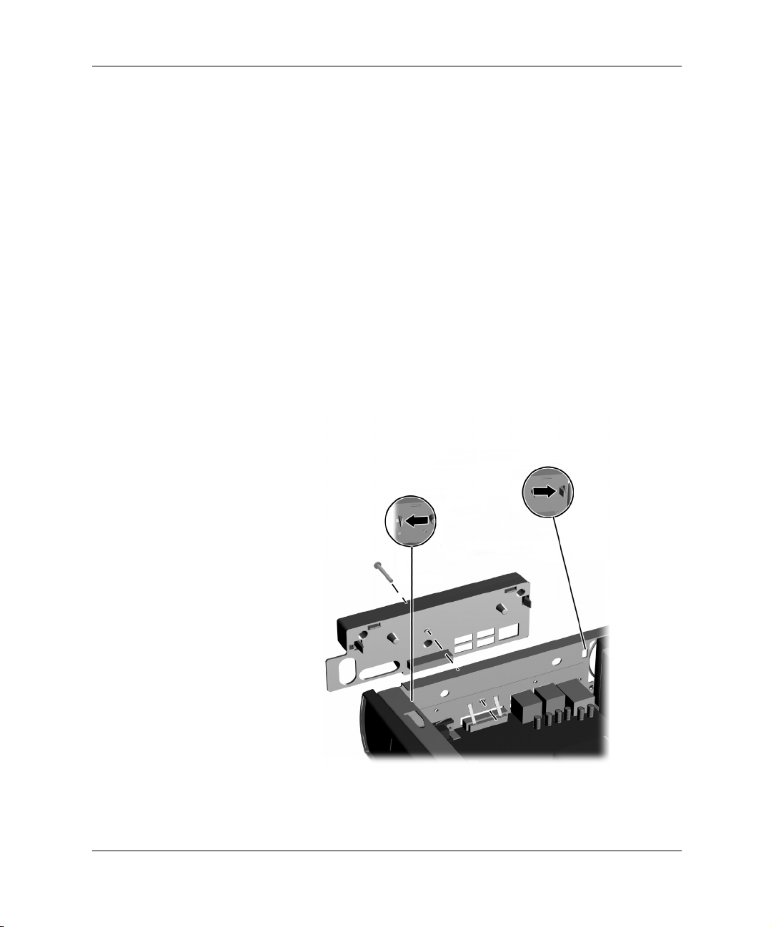
Connecting the Legacy Module
1. Remove the access panel. Refer to “Removing and Replacing the
Access Panel” on page 3-1.
2. Remove the rear panel cover. Refer to “Removing the Rear Panel
Cover” on page 4-2.
3. Align the plastic tabs on the Legacy Module with the holes in the
rear panel, then press firmly to seat the Legacy Module into the
Legacy Module connector.
4. Replace the grounding screw.
Using the Legacy Module
Installing the Legacy Module and Grounding Screw
5. Replace the access panel.
Hardware Reference Guide 4–3
Page 26

Using the Legacy Module
Removing the Legacy Module
1. Exit all software applications, shut down the operating system
software, turn off the personal computer and any external devices,
then disconnect the power cord from the power outlet.
2. Remove the access panel. Refer to “Removing and Replacing the
Access Panel” on page 3-1.
3. Remove the grounding screw. Be sure to keep it in a safe place.
4. Press out on the plastic tabs that secure the Legacy Module to the
personal computer, then push them through the holes in the rear
panel to remove the cover.
Removing the Legacy Module
5. Replace the rear panel cover and the grounding screw.
6. Replace the access panel.
4–4 Hardware Reference Guide
Page 27

Using the MultiPort
What is a Wireless LAN?
A LAN is two or more computers that are connected to each other in
order to share files or common equipment such as a printer or a
modem. A wireless LAN provides the same functionality of a wired
network, but it eliminates the need to install networking cables and
other networking equipment. Not only is a wireless LAN easier to
deploy, but it also allows for “roaming.”
What is the Compaq Evo MultiPort?
The Compaq Evo MultiPort provides an integrated wireless LAN
solution for the Compaq Evo D500 Ultra-Slim Desktop personal
computer. With an optional device such as the Compaq 802.11b
MultiPort Module, you can access wireless Local Area Networks,
share a local printer and files with others in your network, access the
Internet, and use the computer in a variety of locations without being
tethered to a network cable.
5
MultiPort combines the antenna and radio into a single assembly,
resulting in improved radio frequency (RF) signal and reduced noise
pick-up for greater data throughput and distance performance. No
expansion cards or special cables are required, and the modules are
compatible with the MultiPort on select Compaq Evo Notebooks.
Visit the Compaq Web site at www.compaq.com, where you will find
technology overview white papers and additional information on the
Compaq Evo MultiPort.
Installing and Using a MultiPort Module
Refer to the documentation included with the MultiPort Module for
detailed installation and configuration instructions.
Hardware Reference Guide 5–1
Page 28

Using the MultiPort
5–2 Hardware Reference Guide
Page 29

Specifications
Compaq Evo D500 Ultra-Slim Desktop Personal
Computer
Desktop Dimensions (in the minitower position; weight is with
MultiBay drive installed)
Height 12.40 in 315 mm
Width 2.7 in 69 mm
Depth 12.8 in 325 mm
Approximate Weight 11.7 lb 5.3 kg
Temperature Range (values subject to change with increasing
altitude above sea level)
Operating 50* to 95*F 10* to 35*C
Nonoperating -22* to 140*F -30* to 60*C
Relative Humidity (noncondensing)
Operating
(28*C max wet bulb)
Nonoperating
(38.7*C max wet bulb)
Mechanical Shock (11ms 1/2 sine shock pulse)
Operating 5 G’s 5 G’s
Nonoperating 20 G’s 20 G’s
Vibration (random, G’s nominal)
Operating
(10 to 300 hz)
Nonoperating
(10 to 500 hz)
10-90% 10-90%
5-95% 5-95%
.25 .25
.50 .50
A
Hardware Reference Guide A–1
Page 30

Compaq Evo D500 Ultra-Slim Desktop Personal
Computer
Maximum Altitude (unpressurized)
Operating 10,000 ft. 3048 m
Nonoperating 30,000 ft. 9144 m
Power Supply
Operating Voltage
Range
Rated Voltage Range 100-240 VAC 100-240 VAC
Rated Line Frequency50-60 Hz 50-60 Hz
Power Output 50 W 50 W
Rated Input Current
(maximum)
This system utilizes a full-ranging power supply. An input voltage
✎
select switch is not required.
Power Dissipation
Maximum 262 BTU/hr. 66 Kg-Cal/hr.
Typical 131 BTU/hr. 33 Kg-Cal/hr.
(Continued)
90-264 VAC 90-264 VAC
1.7 A (@ 100 VAC) 0.85 A (@ 200 VAC)
A–2 Hardware Reference Guide
Page 31

Battery Replacement
The battery that comes with your computer provides power to the
real-time clock and has a minimum lifetime of about three years.
When replacing the battery, use a battery equivalent to the battery
originally installed on your computer. Your computer comes with a
3-volt lithium coin cell battery.
The lifetime of the lithium battery can be extended by plugging the
✎
computer into a live AC wall socket. The lithium battery is only used
when the computer is NOT connected to AC power.
WARNING: Your computer contains an internal lithium manganese dioxide
battery. There is a risk of fire and burns if the battery is not handled properly.
Å
To reduce the risk of personal injury:
■ Do not attempt to recharge the battery.
■ Do not expose to temperatures higher than 60°C (140ºF).
■ Do not disassemble, crush, puncture, short external contacts, or
dispose of in fire or water.
■ Replace the battery only with the Compaq spare designated for this
product.
B
CAUTION: Before replacing the battery, it is important to back up the
Ä
computer CMOS settings. When the battery is removed or replaced, the
CMOS settings will be cleared. Refer to the
information on backing up the CMOS settings.
Batteries, battery packs, and accumulators should not be disposed of
N
together with the general household waste. In order to forward them to
recycling or proper disposal, please use the public collection system or
return them to Compaq, their authorized partners, or their agents.
Hardware Reference Guide B–1
Troubleshooting Guide
for
Page 32

Battery Replacement
CAUTION: Static electricity can damage the electronic components of
Ä
the computer or optional equipment. Before beginning these
procedures, ensure that you are discharged of static electricity by briefly
touching a grounded metal object.
1. Exit all software applications, shut down the operating system
software, turn off the personal computer and any external devices,
then disconnect the power cord from the power outlet.
2. Remove the access panel. Refer to “Removing and Replacing the
Access Panel” on page 3-1.
3. Locate the battery and battery holder on the system board.
4. Depending on the type of battery holder on your system board,
complete the following instructions to replace the battery.
B–2 Hardware Reference Guide
Page 33

Type 1
a. Lift the battery out of its holder.
Battery Replacement
Removing a Coin Cell Battery (Type 1)
b. Slide the replacement battery into position, positive side up.
The battery holder automatically secures the battery in the proper
position.
Type 2
a. To release the battery from its holder, squeeze the metal
clamp that extends above one edge of the battery.
b. When the battery pops up, lift it out.
Hardware Reference Guide B–3
Page 34

Battery Replacement
Removing a Coin Cell Battery (Type 2)
B–4 Hardware Reference Guide
Page 35

Battery Replacement
c. To insert the new battery, slide one edge of the replacement
battery under the holder’s lip with the positive side up. Push
the other edge down until the clamp snaps over the other edge
of the battery.
Replacing a Coin Cell Battery (Type 2)
After the battery has been replaced, use the following steps to
✎
complete this procedure.
5. Replace the access panel.
6. Plug in the computer and turn on power to the computer.
7. Reset the date and time, your passwords, and any special system
setups, using Compaq Computer Setup. Refer to the Computer
Setup Guide.
Hardware Reference Guide B–5
Page 36

Battery Replacement
B–6 Hardware Reference Guide
Page 37

Electrostatic Discharge
A discharge of static electricity from a finger or other conductor may
damage system boards or other static-sensitive devices. This type of
damage may reduce the life expectancy of the device.
Preventing Electrostatic Damage
To prevent electrostatic damage, observe the following precautions:
■ Avoid hand contact by transporting and storing products in
static-safe containers.
■ Keep electrostatic-sensitive parts in their containers until they
arrive at static-free workstations.
■ Place parts on a grounded surface before removing them from
their containers.
■ Avoid touching pins, leads, or circuitry.
C
■ Always be properly grounded when touching a static-sensitive
component or assembly.
Grounding Methods
There are several methods for grounding. Use one or more of the
following methods when handling or installing electrostatic-sensitive
parts:
■ Use a wrist strap connected by a ground cord to a grounded
workstation or personal computer chassis. Wrist straps are
flexible straps with a minimum of 1 Mohm +/- 10 percent
resistance in the ground cords. To provide proper ground, wear
the strap snug against the skin.
Hardware Reference Guide C–1
Page 38

Electrostatic Discharge
✎
■ Use heelstraps, toestraps, or bootstraps at standing workstations.
Wear the straps on both feet when standing on conductive floors
or dissipating floor mats.
■ Use conductive field service tools.
■ Use a portable field service kit with a folding static-dissipating
work mat.
If you do not have any of the suggested equipment for proper
grounding, contact your Compaq authorized service provider.
For more information on static electricity, contact your Compaq
authorized service provider.
C–2 Hardware Reference Guide
Page 39

Routine Care
D
Routine Care & Shipping Information
Follow these suggestions to take care of your personal computer and
monitor:
■ Operate the personal computer on a sturdy, level surface. Leave a
3-inch (7.6-cm) clearance at the back of the system unit and
above the monitor to permit the required airflow.
■ Never operate the personal computer with the cover or side panel
removed.
■ Never restrict the airflow into the personal computer by blocking
the air intake or exhaust vents.
■ Keep the personal computer away from excessive moisture, direct
sunlight, and extremes of heat and cold. For information about
the recommended temperature and humidity ranges for your
personal computer, refer to the Specifications in Appendix A.
Keep liquids away from the personal computer and keyboard.
■ Never cover the ventilation slots on the monitor with any type of
material.
■ Turn off the personal computer before you do either of the
following:
❏ Wipe the exterior of the personal computer with a soft, damp
cloth as needed. Using cleaning products may discolor or
damage the finish.
❏ Occasionally clean the air intake and exhaust vents on the
personal computer. Lint and other foreign matter can block
the vents and limit the airflow.
Hardware Reference Guide D–1
Page 40

Routine Care & Shipping Information
CD-ROM Drive Precautions
Be sure to observe the following guidelines while operating or
cleaning your CD-ROM drive.
Operation
■ Do not move the drive during operation. This may cause it to
malfunction during reading.
■ Avoid exposing the drive to sudden changes in temperature, as
condensation may form inside the unit. If the temperature
suddenly changes while the drive is on, wait at least one hour
before you turn off the power. If you operate the unit
immediately, it may malfunction while reading.
■ Avoid placing the drive in a location that is subject to high
humidity, extreme temperatures, mechanical vibration, or direct
sunlight.
Cleaning
■ Clean the panel and controls with a soft, dry cloth or a soft cloth
lightly moistened with a mild detergent solution. Never spray
cleaning fluids directly on the unit.
■ Avoid using any type of solvent, such as alcohol or benzene,
which may damage the finish.
Safety
If any object or liquid falls into the drive, immediately unplug the
personal computer and have it checked by an authorized Compaq
service provider.
Shipping Preparation
Follow these suggestions when preparing to ship your personal
computer:
1. Back up the hard drive files onto the network or removable
media. Be sure that the backup media is not exposed to electrical
or magnetic impulses while stored or in transit.
D–2 Hardware Reference Guide
Page 41

Routine Care & Shipping Information
The hard drive locks automatically when the system power is turned
✎
off.
2. Remove and store separately any removable media and MultiBay
drives.
3. Turn off the personal computer and external devices.
4. Disconnect the power cord from the electrical outlet, then from
the personal computer.
5. Disconnect the system components and external devices from
their power sources, then from the personal computer.
6. Pack the system components, MultiBay drives, and external
devices in their original packing boxes or similar packaging with
sufficient packing material to protect them.
For environmental nonoperating ranges, refer to Appendix A,
✎
“Specifications.”
Hardware Reference Guide D–3
Page 42

Routine Care & Shipping Information
D–4 Hardware Reference Guide
Page 43

Index
1.44-MB diskette drive 2–1
802.11b
5–1
A
access panels. See access panels
B
battery
replacement
B–1
C
care of equipment D–1
caring for MultiBay drives
cautions
memory contacts
prevention of data loss
2–2
static electricity
CD-ROM drive
cleaning and safety
CD-RW drive
components
rear panel
connector
parallel (Legacy Module)
PS/2 keyboard (Legacy
Module)
PS/2 mouse (Legacy Module)
4–1
serial (Legacy Module)
3–1, 3–3
2–1
2–1
4–1
4–1
2–1
3–3
2–1,
D–2
4–1
4–1
D
DVD-ROM drive 2–1
E
Easy Access Buttons 1–1
Easy Access Keyboard
electrostatic discharge
Enhanced Keyboard
C–1
1–1
F
formatting a MultiBay hard drive
2–3
G
grounding methods C–1
H
hard drive 3–1
MultiBay
partitioning and formatting
2–3
hard drive, removing and
replacing internal
2–1, 2–3
3–7
I
internal hard drive 3–1
K
keyboard
Windows Logo Key
keyboard programming
L
Legacy Module 4–1
M
memory 3–1
adding or removing modules
3–3 to 3–6
specifications
1–2
mouse
MultiBay
3–3
1–1
1–2
1–1
Hardware Reference Guide Index–1
Page 44

Index
hot-plugging or
hot-swapping drives
inserting drives
partitioning and formatting a
hard drive
removable drives
removing drives
MultiPort
2–3
5–1
2–2
2–5
2–1
2–6
N
network communications 5–1
notes
drive blank
Legacy Module
memory module installation
3–6
signal cable removal
2–5, 2–6
4–1
3–8
P
packaging guidelines D–2
partitioning a MultiBay hard
2–3
drive
programming, keyboard
1–1
R
rear panel components 4–1
removable drives, optional
S
shipping guidelines D–2
side access panels
removing and replacing
SMART hard drive
specifications
SuperDisk LS-120 drive
2–1
A–1
U
upgrading the personal computer
3–1
W
warnings
electrical shock
hot surfaces
Windows Logo Key
wireless LAN
WLAN
5–1
3–1
3–5
1–2
5–1
2–1
3–1
2–1
Index–2 Hardware Reference Guide
 Loading...