

Page 1
Illustrated Parts & Service Map
HP Compaq dx7500 Business PC
Microtower Chassis
© 2008 Hewlett-Packard Development Company, L.P. The information con-
tained herein is subject to change without notice. HP shall not be liable for
technical or editorial errors or omissions contained herein. Intel, Pentium,
Intel Inside, and the Intel logo are trademarks or registered trademarks of the
Intel Corporation and its subsidiaries in the U. S. and other countries.
Document Number 506597-001. 1st Edition September 2008.
Key Specifications
Processor Type Intel Celeron, Pentium Dual-Core, Core2 Duo, Core2 Quad
RAM Type DDR2-SDRAM DIMMs, PC2-6400 (800 MHz) non-ECC
Maximum RAM Supported 16 GB
Expansion Slots • 3 PCIe-x1 (full height)
Graphics Adapter Intel Graphics Media Accelerator X4500HD with DX10 sup-
Drive Support • 2 hard disk drives
Bays • 2 external 5.25-inch
I/O Interfaces PS/2 (keyboard & mouse), VGA, DVI-D, 1394, SPDIF in &
• 1 PCIe-x16 (full height)
port
• 2 optical disk drives
• floppy diskette drive, media card reader
• 1 external 3.5-inch
• 2 internal 3.5-inch
out, line in, line out, mic in, RJ-45, USB 2.0 (10)
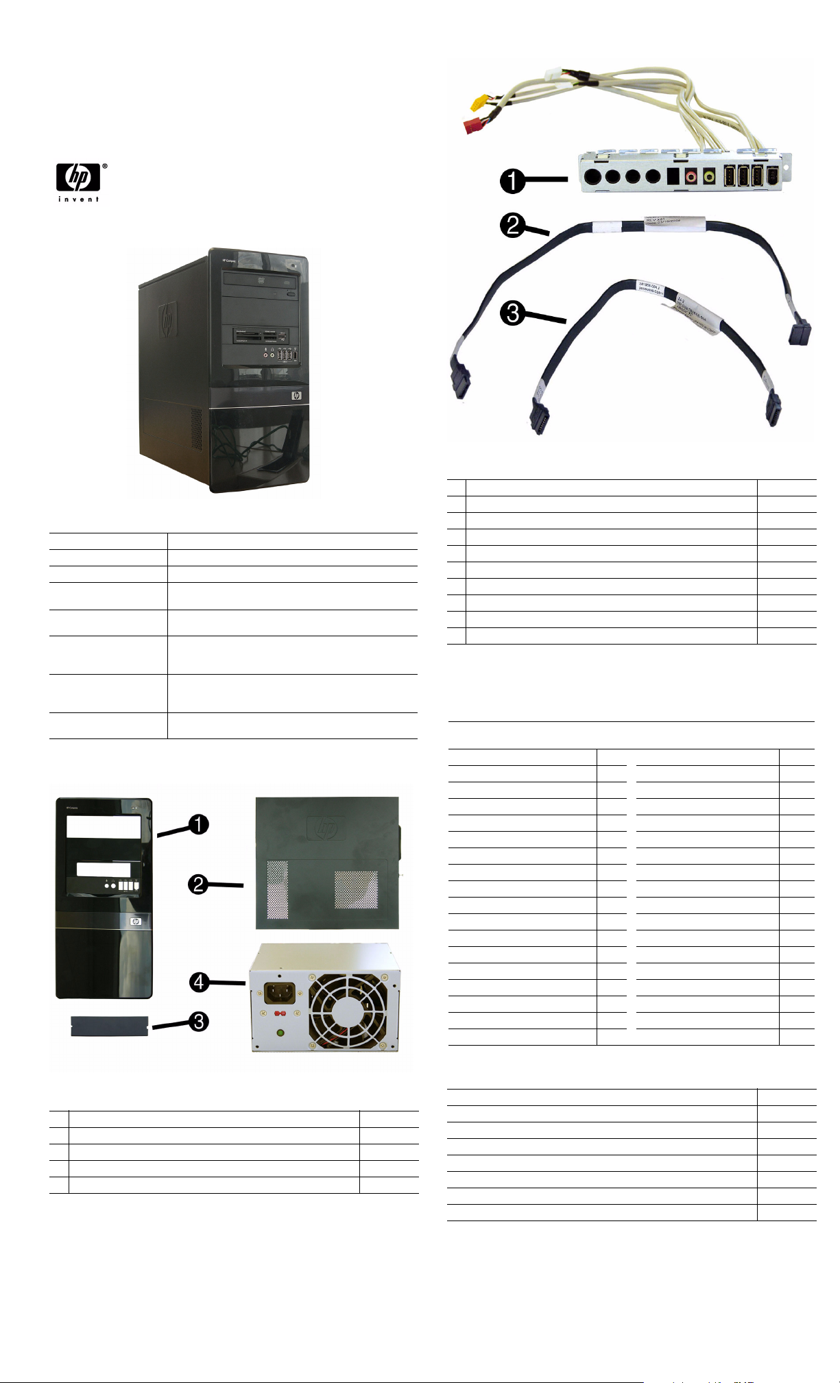
Spare Parts
Cables
1 Front I/O, 3 USB, 1394 assembly 487744-001
2 SATA hard drive cable, 13 inch 391738-001
3 SATA cable, 10 inch, 2 straight ends 392307-001
* Power switch/LED assembly 464574-001
* SATA hard drive cable with latch, 6.5 inch 448670-001
* SATA power dongle, 4 inch 449283-001
* Diskette drive cable 395967-001
* DVI cable 484156-001
* DMS-59 to dual VGA cable 463023-001
* Adapter, DVI to VGA 202997-001
*Not shown
Keyboards (not illustrated)
PS/2, Basic
USB, Basic
Arabic -171 LA Spanish -161
Belgian -181 Norwegian -091
BHCSY -B41
Brazilian Portuguese -201 Portuguese -131
Bulgarian -261 Romanian -271
Czech -221 Russian -251
Danish -081
Finnish -351 Slovakian -231
French -051 South Korea -KD1
French Canadian -121
German -041 Swedish -101
Greek -151 Swiss -111
Hebrew -BB1 Taiwanese -AB1
Hungarian -211 Thai -281
International -B31
International English -L31
Italian -061 U.K. -031
Japanese -291
435302-xxx
435382-xxx
People’s Republic of China
Saudi Arabia -DE1
Spanish -071
Turkish -141
U.S. -001
-AA1
Mass Storage Devices (not illustrated)
System Unit
1 Front bezel 487746-001
2 Access panel 464597-001
3 5.25-inch bezel blank 335937-001
4 Power supply, 300W, PFC 463317-001
4 Power supply, 300W, NPFC 463318-001
Diskette drive with bezel 431452-001
16X SATA DVD±RW and CD-RW drive with LightScribe 447310-001
16X SATA DVD-ROM drive 419496-001
500 GB, 7200-RPM SATA hard drive, 3.5-inch 457909-001
320 GB, 7200-RPM SATA hard drive, 3.5-inch 497731-001
250 GB, 7200-RPM SATA hard drive, 3.5-inch 449980-001
160 GB, 10000-RPM SATA hard drive, 2.5-inch with adapter 449979-001
80 GB, 7200-RPM SATA hard drive, 3.5-inch 449978-001
dx7500 Illustrated Parts & Service Map, MT chassis 506597-001 page 1
Page 2
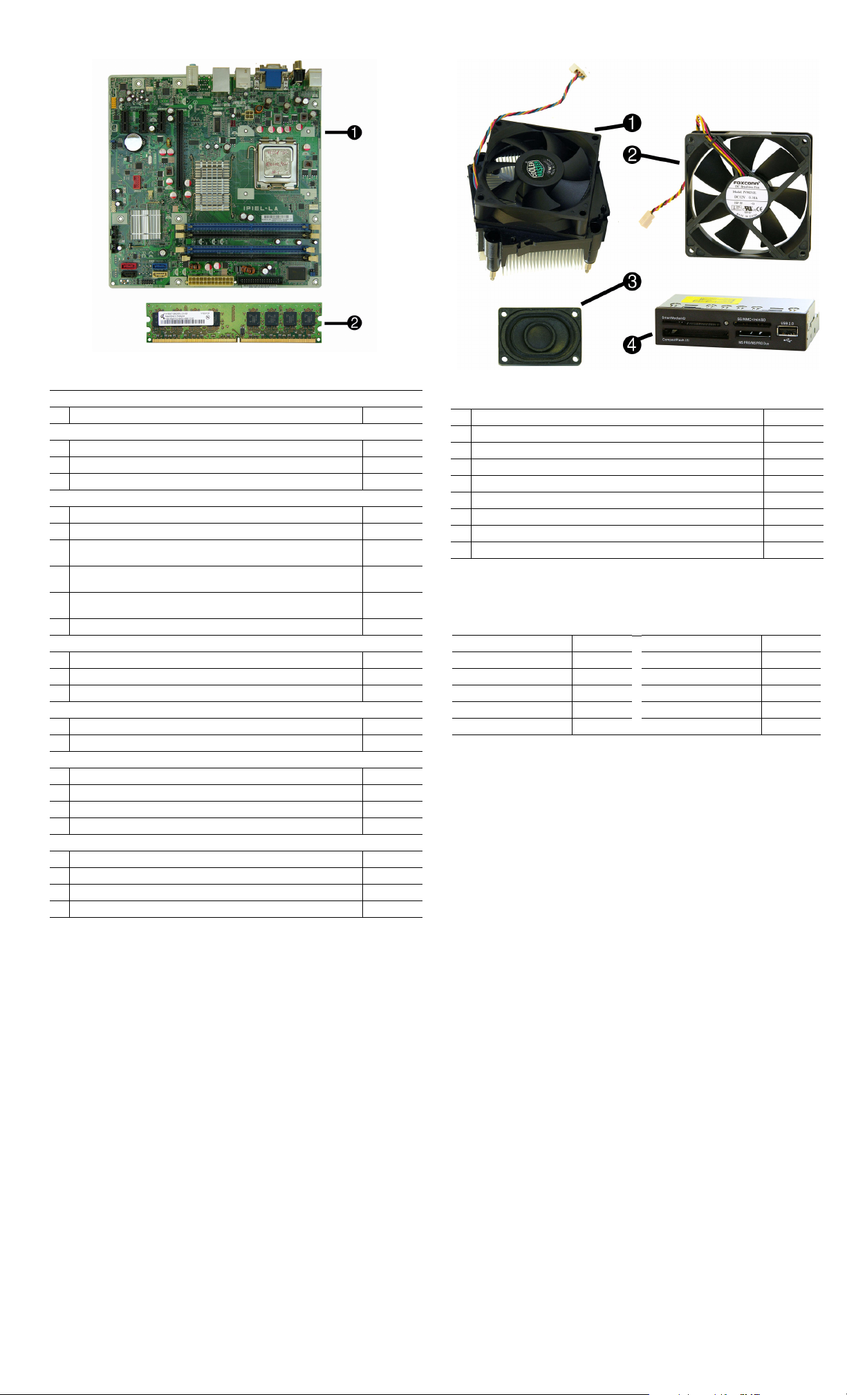
Standard and Optional Boards
System boards with thermal grease, alcohol pad, and CPU socket cover
1 System board 487741-001
Memory modules (PC2-6400, CL5)
2 512 MB (PC2-6400)
2 1 GB (PC2-6400)
2 2 GB (PC2-6400)
Other boards
* Saffron WLAN 802.11b/g/n for use world-wide, includes bracket 498307-001
* Agere International 56K LSI v92 modem, includes bracket 490689-001
* ATI HD2400 (RV610) 256-MB graphics card, one DMS59 connector and
one S-Video connector, low profile with ATX bracket
* ATI HD3650 (RV635) 512-MB graphics card, two DP 1.1a connectors,
one dual-link DVI connector, includes bracket
* ATI HD3470 (RV620) 256-MB graphics card, one DP 1.1a connector, one
dual-link DVI connector, includes bracket
* Intel Gigabit NIC, includes bracket 490367-001
Intel Celeron Processors with alcohol pad and thermal grease
* E1400, 2.0 GHz, 512-KB L2 cache, dual core 491574-001
* E1200, 1.6 GHz, 512-KB L2 cache, dual core 468589-001
440, 2.0 GHz, 512-KB L2 cache 449166-001
Intel Pentium Dual Core Processors with alcohol pad and thermal grease
* E5200, 2.5 GHz, 2-MB L2 cache 503382-001
* E2200, 2.2 GHz, 1-MB L2 cache 465216-001
Intel Core 2 Quad Processors with alcohol pad and thermal grease
* Q9550, 2.83 GHz, 12-MB L2 cache 465758-001
* Q9400, 2.66 GHz, 6-MB L2 cache 497733-001
* Q8200, 2.33 GHz, 4-MB L2 cache 503381-001
* Q6600, 2.4 GHz, 8-MB L2 cache 452451-001
Intel Core 2 Duo Processors with alcohol pad and thermal grease
* E8600, 3.33 GHz, 6-MB L2 cache 497732-001
* E8500, 3.16 GHz, 6-MB L2 cache 466170-001
* E8400, 3.00 GHz, 6-MB L2 cache 466169-001
* E7300, 2.66 GHz, 3-MB L2 cache 500134-001
* Not shown
418952-001
418951-001
457624-001
462477-001
481421-001
483951-001
Miscellaneous Parts
1 Heatsink with alcohol pad and factory-applied thermal grease 486445-001
2 Chassis fan 449207-001
3 Internal speaker 463316-001
4
Media card reader, 3.5-inch, includes 5.25-inch conversion kit 480033-001
* Foot kit 370708-001
* Mouse, PS2, optical 417966-001
* Mouse, optical 390938-001
* Mouse, laser 459821-001
* Modem cable 198220-001
*Not shown
Modem RJ-11 adapters (not illustrated)
Czechoslovakian 234963-225 Polish 316904-241
French 316904-051 Saudi Arabian 316904-AR1
German 316904-045 Scandinavian 382848-DH1
Greek 316904-151 Turkish 316904-141
Hungarian 234963-215 United Kingdom 158593-035
Israel 316904-BB1
dx7500 Illustrated Parts & Service Map, MT chassis 506597-001 page 2
Page 3

System Board System Setup and Boot
Basic system information regarding system information, setup, power management, hardware,
and passwords is maintained in the Setup Utility held in the system ROM. The Setup Utility is
accessed by pressing the F10 key when prompted (on screen) to do so during the boot sequence.
If the screen prompt opportunity is missed, a restart will be necessary. For more information
about Setup Utilities refer to the Service Reference Guide..
Computer Setup Menu
Heading Option / Description
Main System Time Allows you to set system time.
System Date Allows you to set system date.
Language Allows you to select the language.
Floppy Diskette A Allows you to set to Disabled, 1.44 MB 3.5”, Not
1st Drive
2nd Drive
3rd Drive*
4th Drive*
5th Drive
6th Drive
System Information Allows you to view installed memory, memory banks 1-
Advanced CPU Type View only.
CPU Speed View only.
Cache RAM View only.
System Board Connectors and Jumpers (component location may vary)
CMOS+PW CMOS/Password header F_USB2 Media card reader connector
1394+USB Stacked 1394/Double USB
LAN+USB Stacked RJ-45/Double USB
PCIE_X1_1 PCIe X1,slot 1 CHASSIS_
PCIE_X1_2 PCIe X1, slot 2 F_AUDIO Front audio connector
PCIE_X1_3 PCIe X1, slot 3 SATA0 Primary SATA hard drive
PCIE_X16 PCIe X16, slot SATA1 1st SATA optical drive
DVI_VGA Stacked DVI/VGA connector SATA4 2nd SATA hard drive
AUDIO Double stack audio connector SATA5 2nd SATA optical drive
AT X_
POWER
ATX_CPU CPU power connector DIMM 1 Memory socket 1
F_PANEL Front panel connector DIMM 2 Memory socket 2
SPEAKER Internal speaker connector DIMM 3 Memory socket 3
CPU FAN CPU/heatsink fan connector DIMM 4 Memory socket 4
FLOPPY Diskette drive connector PROCES-
F_USB1 1st USB header SPDIF_I/O Digital line-in/line-out audio
POST Audible Codes
Beeps Meaning Recommended Action
1 short beep and 1 long beep
followed by a three second
pause
2 short beeps and 1 long
beep followed by a three
second pause
3 short beeps and 1 long
beep followed by a three
second pause
1 short beep followed by a
one second pause
2 short beeps followed by a
three second pause
3 short beeps followed by a
three second pause
4 short beeps followed by a
three second pause
5 short beeps followed by a
three second pause
connector
connectors
Main power connector F_1394 1394 header
Bad memory or
memory configuration error.
No graphics card
installed or graphics
card initialization
failed.
CPU configuration
error or invalid CPU
detected before
graphics card initialized.
No legacy floppy
drive or optical drive
found.
No floppy diskette or
CD found.
Flashing not ready
(missing utility or
BIOS image file,
etc.)
Flashing operation
has failed (checksum
error, corrupted
image, etc.)
BIOS recovery was
successful
F_USB5 3rd USB header
F_USB6 4th USB header
FAN1
SOR
Rear fan connector
Processor socket
connectors
Check that the memory modules have
been installed correctly and that proper
modules are used.
For systems with a graphics card:
1. Reseat the graphics card. Power on
the system.
2. Replace the graphics card.
3. Replace the system board.
For systems with integrated graphics,
replace the system board.
1. Upgrade the BIOS to proper version.
2. Change the processor.
1. Check cable connections.
2. Run the Computer Setup utility and
ensure the device port is enabled.
1. Check the type of drive that you are
using and use the correct media
type.
2. Replace the diskette or CD with a
new one.
Upgrade the BIOS to proper version.
1. Verify the correct ROM.
2. Flash the ROM if needed.
3. If an expansion board was recently
added, remove it to see if the problem remains.
4. Clear CMOS.
5. If th e message disappears, there may
be a problem with the expansion
card.
6. Replace the system board.
No action required.
Power After AC Power Fail-
Boot Boot-time Diagnostic
Exit Exit Saving Changes Press Enter to exit saving changes.
Primary Video
Adapter
Onboard Video Memory Size
PS/2 Mouse Disable/enable/auto detect
USB Ports Disable/enable all USB ports.
Onboard LAN Disable/enable onboard LAN controller.
Onboard LAN Boot
ROM
SATA1 Controller Disable/enable the SATA1 controller
SATA1 Controller
Mode
Onboard Audio Auto/disable/enable.
Internal Speaker Disable/enable.
Supervisor Password Allows you to view the supervisor password.
User Password Allows you to view the user password.
Onboard 1394 Disable/enable all 1394 ports.
Change Supervisor
Password
ure
XD Disable/enable XD bit.
Virtualization Technology
Screen
1st Boot Device, 2nd
Boot Device, 3rd
Boot Device, 4th Boot
Device
Floppy Group Boot
Priority
CD-ROM Boot Priority
Hard Drive Boot Priority
Network Group Boot
Priority
Exit Discarding
Changes
Load Setup Defaults Press Enter to load setup defaults.
Discard Changes Press Enter to discard changes.
Save Changes Press Enter to save changes.
Installed.
Allow you to: view capacity, transfer mode. Also allows
you to run HDD self-test for selected channel: SMART
status check, SMART short self test, SMART extended
self test.
*3rd and 4th Drive not used.
4, BIOS revision, core version, model number, product
number, asset tag (press Enter to change).
Allows you to select boot display device when more
than 2 video options are offered by system: Integrated
(Onboard), PCI, PCI-Ex16, PCI-Ex1.
1 MB, 8 MB.
Disable/enable the boot ROM of the onboard LAN chip.
If SATA1 controller enabled, allows you to set the mode
to IDE, AHCI, or RAID.
Allows you to change the supervisor password.
Allows you to select system restart behavior after power
loss: Stay off, Power on, Auto.
Disable/enable.
Disable/enable POST diagnostic messages display.
Allows you to specify which device groups will boot
first, second, third, and fourth or to disable any
of the four: Floppy group, CD-ROM group, Hard drive
group, Network boot group. MS-DOS drive lettering
assignments maybe apply after a non-MS-DOS operating system has started.
Specifies boot device priority within removable devices.
Specifies boot device priority within CD/DVD drives.
Specifies boot device priority within hard drives.
Specifies boot device priority within bootable network
devices.
Press Enter to exit discarding changes.
dx7500 Illustrated Parts & Service Map, MT chassis 506597-001 page 3
Page 4

Boot Block Emergency Recovery Mode
Boot Block Emergency Recovery Mode permits system recovery in the unlikely event of a ROM
flash failure. For example, if a power failure were to occur during a BIOS upgrade, the ROM
flash would be incomplete. This would render the system BIOS unusable. The Boot Block is a
flash-protected section of the ROM that contains code that checks for a valid system BIOS
image when the system is turned on.
• If the system BIOS image is valid, the system starts normally.
• If the system BIOS image is not valid, a failsafe Boot Block BIOS provides enough support
to search removable media for BIOS image files. If an appropriate BIOS image file is found,
it is automatically flashed into the ROM.
When an invalid system BIOS image is detected, the system power LED will blink red 8 times,
one blink every second. Simultaneously, the speaker will beep 8 times. If the portion of the
system ROM containing the video option ROM image is not corrupt, Boot Block Emergency
Recovery Mode will be displayed on the screen.
To recover the system after it enters Boot Block Emergency Recovery Mode, complete the
following steps:
Boot Block Recovery
1. Remove any bootable media from the computer and turn off power.
2. Insert a USB flash device or CD containing the BIOS image file in the root directory. The
media must be formatted using the FAT12, FAT16, or FAT32 file system.
3. Turn on power to the system.
4. The system automatically reprograms the ROM.
NOTE: BitLocker prevents Windows Vista from booting when a CD containing the BIOS image
file is in an optical drive. If BitLocker is enabled, remove this CD before attempting to boot to
Wind ows Vist a.
Password Security
If the system is equipped with an embedded security device, refer to the HP ProtectTools
Security Manager Guide at http://www.hp.com. Establishing a setup password through
Computer Setup prevents reconfiguration of the computer (use of the Computer Setup (F10)
utility) until the password is entered.
Establishing a Setup or Power-On password
1. Turn on or restart the computer. If you are in Windows, click Start > Shut Down >Restart.
2. As soon as the computer is turned on, press F10 when the monitor light turns green to enter
Computer Setup. Press Enter to bypass the title screen, if necessary. If you do not press F10
when prompted, a restart will be necessary.
3. To establish a Setup password, select Security > Setup Password and follow the instructions
on the screen.
- or To establish a Power-On password, select Security > Power-On Password and follow the
instructions on the screen
4. Before exiting, click File > Save Changes and Exit.
Changing a Setup or Power-On password
If the system is equipped with an embedded security device, refer to the HP ProtectTools Security Manager Guide at http://www.hp.com.
1. Turn on or restart the computer. If you are in Windows, click Start > Shut Down > Restart.
To change the Setup password, go to step 2.
To change the Power-on password, go to step 3.
2. To change the Setup password, as soon as the computer is turned on, press F10 when the
monitor light turns green to enter Computer Setup. Press Enter to bypass the title screen, if
necessary.
3. When the key icon appears, type your current password, a slash (/) or alternate delimiter
character, your new password, another slash (/) or alternate delimiter character, and your new
password again as shown:
current password/new password/new password.
NOTE: Type the new password carefully since the characters do not appear on the screen.
4. Press Enter.
The new password will take effect the next time the computer is restarted.
Deleting a Power-On or Setup password
If the system is equipped with an embedded security device, refer to the HP ProtectTools Security Manager Guide at http://www.hp.com.
1. Turn on or restart the computer. If you are in Windows, click Start > Shut Down > Restart.
To delete the Setup password, go to step 2.
To delete the Power-On password, go to step 3.
2. To change the Setup password, as soon as the computer is turned on, press F10 when the
monitor light turns green to enter Computer Setup. Press Enter to bypass the title screen, if
necessary.
3. When the key icon appears, type your current password followed by a slash (/) or alternate
delimiter character as shown. Example: currentpassword/
4. Press Enter.
HP Insight Diagnostics
Diagnostic functions are provided by the Setup Utility (in system ROM) and by HP Insight
Diagnostics. The HP Insight Diagnostics utility allows you to view information about the hardware configuration of the computer and perform hardware diagnostic tests on the subsystems of
the computer. The utility simplifies the process of effectively identifying, diagnosing, and isolating hardware issues.
Insight Diagnostics may be downloaded from the HP Web site using the following procedure:
1. Go to www.hp.com
2. Click the Software & Download driver link.
3. Enter the product number (for example, dc7500) in the text box and press the Enter key.
4. Select the specific product.
5. Select the OS.
6. Click the Diagnostics link.
7. Select HP Insight Diagnostics Offline Edition.
8. Click Download.
NOTE: The download includes instructions on how to create a bootable CD.
Clearing CMOS
1. Turn off the computer and any external devices, and disconnect the power cord from the
power outlet.
2. Remove the chassis access panel.
3. Locate the jumper labeled E69.
4. Remove the blue CMOS jumper from pins 4 and 6 and put the jumper on pins 2 and 4. This
clears CMOS.
5. Put the jumper back on pins 4 and 6.
6. Replace the chassis access panel and reconnect the power cord.
7. Turn on the computer and allow it to start.
dx7500 Illustrated Parts & Service Map, MT chassis 506597-001 page 4
 Loading...