

Page 1

HP Compaq 6515b Notebook PC and
HP Compaq 6510b Notebook PC
Maintenance and Service Guide
Page 2

© Copyright 2007, 2008 Hewlett-Packard
Development Company, L.P.
AMD, Sempron, Turion, and combinations
thereof are trademarks of Advanced Micro
Devices, Inc. Bluetooth is a trademark
owned by its proprietor and used by HewlettPackard Company under license. Intel and
Core are trademarks or registered
trademarks of Intel Corporation or its
subsidiaries in the United States and other
countries. Java is a US trademark of Sun
Microsystems, Inc. Microsoft, Windows, and
Windows Vista are either trademarks or
registered trademarks of Microsoft
Corporation in the United States and/or other
countries. SD Logo is a trademark of its
proprietor.
The information contained herein is subject
to change without notice. The only
warranties for HP products and services are
set forth in the express warranty statements
accompanying such products and services.
Nothing herein should be construed as
constituting an additional warranty. HP shall
not be liable for technical or editorial errors
or omissions contained herein.
Third Edition: September 2008
First Edition: March 2007
Document Part Number: 443118-003
Page 3

Safety warning notice
WARNING! To reduce the possibility of heat-related injuries or of overheating the computer, do not
place the computer directly on your lap or obstruct the computer air vents. Use the computer only on a
hard, flat surface. Do not allow another hard surface, such as an adjoining optional printer, or a soft
surface, such as pillows or rugs or clothing, to block airflow. Also, do not allow the AC adapter to contact
the skin or a soft surface, such as pillows or rugs or clothing, during operation. The computer and the
AC adapter comply with the user-accessible surface temperature limits defined by the International
Standard for Safety of Information Technology Equipment (IEC 60950).
iii
Page 4

iv Safety warning notice
Page 5

Table of contents
1 Product description
2 External component identification
Top components ................................................................................................................................. 10
Buttons, switches, and fingerprint reader .......................................................................... 10
Lights ................................................................................................................................. 12
Keys ................................................................................................................................... 13
TouchPad .......................................................................................................................... 14
Front components .............................................................................................................................. 15
Left-side components ......................................................................................................................... 16
Rear components ............................................................................................................................... 17
Right-side components ....................................................................................................................... 17
Bottom components ........................................................................................................................... 18
3 Illustrated parts catalog
Serial number location ........................................................................................................................ 19
Computer major components ............................................................................................................. 20
Plastics Kit .......................................................................................................................................... 28
Cable Kit ............................................................................................................................................. 29
Mass storage devices ......................................................................................................................... 30
Miscellaneous parts ............................................................................................................................ 31
Sequential part number listing ............................................................................................................ 32
4 Removal and replacement procedures
Preliminary replacement requirements ............................................................................................... 39
Tools required .................................................................................................................... 39
Service considerations ....................................................................................................... 39
Plastic parts ....................................................................................................... 39
Cables and connectors ..................................................................................... 40
Drive handling ................................................................................................... 40
Grounding guidelines ......................................................................................................... 41
Electrostatic discharge damage ........................................................................ 41
Packaging and transporting guidelines ............................................. 42
v
Page 6

Workstation guidelines ..................................................................... 42
Equipment guidelines ....................................................................... 43
Unknown user password ................................................................................................... 44
Component replacement procedures ................................................................................................. 45
Serial number .................................................................................................................... 45
Battery ............................................................................................................................... 46
SIM .................................................................................................................................... 47
Display inverter .................................................................................................................. 48
Hard drive .......................................................................................................................... 50
Computer feet .................................................................................................................... 52
Bluetooth module ............................................................................................................... 52
Expansion memory module ............................................................................................... 54
WLAN module .................................................................................................................... 56
Optical drive ....................................................................................................................... 60
Keyboard ........................................................................................................................... 62
Internal memory module .................................................................................................... 65
RTC battery ....................................................................................................................... 66
WWAN module .................................................................................................................. 67
Switch cover ...................................................................................................................... 68
Fan ..................................................................................................................................... 69
Heat sink ............................................................................................................................ 71
Processor ........................................................................................................................... 73
Display assembly ............................................................................................................... 75
Top cover ........................................................................................................................... 79
Speaker assembly ............................................................................................................. 83
Media Card Reader/USB connector board ........................................................................ 84
System board ..................................................................................................................... 86
PC Card/audio board assembly ......................................................................................... 89
Modem module .................................................................................................................. 90
SIM slot board .................................................................................................................... 92
5 Computer Setup
Starting Computer Setup .................................................................................................................... 94
Using Computer Setup ....................................................................................................................... 95
Computer Setup menus ..................................................................................................................... 96
6 Specifications
vi
Navigating and selecting in Computer Setup ..................................................................... 95
Restoring factory settings in Computer Setup ................................................................... 95
File menu ........................................................................................................................... 96
Security menu .................................................................................................................... 97
Diagnostics menu .............................................................................................................. 98
System Configuration menu .............................................................................................. 98
Page 7

Computer specifications ................................................................................................................... 100
14.1-inch, WXGA+ display specifications ......................................................................................... 101
Hard drive specifications .................................................................................................................. 102
Primary 6-cell, Li-ion battery specifications ...................................................................................... 103
DVD±RW and CD-RW Super Multi Double-Layer Combo Drive specifications ............................... 104
DVD/CD-RW Combo Drive specifications ........................................................................................ 105
DVD-ROM drive ............................................................................................................................... 106
System DMA specifications .............................................................................................................. 107
System interrupt specifications ......................................................................................................... 108
System I/O address specifications ................................................................................................... 109
System memory map specifications ................................................................................................. 111
7 Screw listing
Phillips PM2.0×5.0 captive screw ..................................................................................................... 113
Phillips PM2.5×13.0 captive screw ................................................................................................... 114
Phillips PM3.0×3.0 screw ................................................................................................................. 115
Phillips PM2.5×3.0 screw ................................................................................................................. 116
Torx T8M2.5×9.0 screw ................................................................................................................... 118
Phillips PM2.0×3.0 screw ................................................................................................................. 120
Black Phillips PM2.5×8.0 captive screw ........................................................................................... 122
Torx T8M2.5×17.0 screw ................................................................................................................. 123
Torx T8M2.5×7.0 screw ................................................................................................................... 124
Torx T8M2.5×6.0 screw ................................................................................................................... 125
Hex HM5.0×9.0 screw lock .............................................................................................................. 126
Phillips PM2.5×5.0 screw ................................................................................................................. 127
Silver Phillips PM2.5×8.0 captive screw ........................................................................................... 129
Phillips PM2.5×8.0 screw ................................................................................................................. 130
Phillips PM2.0×6.0 screw ................................................................................................................. 131
8 Backup and recovery
Backup and recovery in Windows Vista ........................................................................................... 132
Creating recovery discs ................................................................................................... 132
Backing up your information ............................................................................................ 132
Performing a recovery ..................................................................................................... 135
When to back up ............................................................................................. 133
Backup suggestions ........................................................................................ 133
Backing up specific files or folders .................................................................. 133
Backing up the entire hard drive ..................................................................... 134
Creating recovery points ................................................................................. 134
Scheduling backups ........................................................................................ 135
Performing a recovery from the recovery discs ............................................... 135
Performing a recovery from the hard drive ...................................................... 135
Initiating a recovery in Windows ..................................................... 136
vii
Page 8

Backup and recovery in Windows XP .............................................................................................. 137
Creating recovery discs ................................................................................................... 137
Backing up your information ............................................................................................ 137
Performing a recovery ..................................................................................................... 140
9 Connector pin assignments
Audio-out (headphone) ..................................................................................................................... 142
Audio-in (microphone) ...................................................................................................................... 142
External monitor ............................................................................................................................... 143
RJ-11 (modem) ................................................................................................................................ 144
RJ-45 (network) ................................................................................................................................ 144
S-Video-out ...................................................................................................................................... 145
Universal Serial Bus ......................................................................................................................... 145
Initiating a recovery from the hard drive recovery partition ............. 136
When to back up ............................................................................................. 138
Backup suggestions ........................................................................................ 138
Backing up specific files or folders .................................................................. 138
Backing up the entire hard drive ..................................................................... 139
Creating recovery points ................................................................................. 139
Scheduling backups ........................................................................................ 140
Performing a recovery from the recovery discs ............................................... 140
Performing a recovery from the hard drive ...................................................... 140
Initiating a recovery in Windows ..................................................... 141
Initiating a recovery from the hard drive recovery partition ............. 141
10 Power cord set requirements
Requirements for all countries or regions ......................................................................................... 146
Requirements for specific countries or regions ................................................................................ 147
11 Recycling
Battery .............................................................................................................................................. 148
Display .............................................................................................................................................. 148
Index ................................................................................................................................................................. 154
viii
Page 9

1 Product description
Category Description HP Compaq 6515b
Notebook PC without
WWAN
Processors AMD Turion™ 64 Mobile Technology
processors:
TL-64 (dual-core) 2.2-GHz (1 MB of L2 cache)
●
MK-38 (single-core) 2.2-GHz (512 KB of L2
●
cache)
TL-60 (dual-core) 2.0-GHz (1 MB of L2 cache)
●
TL-56 (dual-core) 1.8-GHz (1 MB of L2 cache)
●
TL-52 (dual-core) 1.6-GHz (1 MB of L2 cache)
●
TL-50 (dual-core) 1.6-GHz (1 MB of L2 cache)
●
Mobile AMD Sempron™ processors:
3800+ 2.2-GHz (256 KB of L2 cache)
●
3600+ 2.0-GHz (256 KB of L2 cache)
●
3500+ 1.8-GHz (512 KB of L2 cache)
●
3400+ 1.8-GHz (256 KB of L2 cache)
●
Chipsets
Northbridge: RS690T
●
√ √
√ √
√ √
HP Compaq 6515b
Notebook PC with
WWAN
Southbridge: SB600
●
Graphics Unified Memory Architecture (UMA), integrated with
shared video memory
Panels
Memory
14.1-inch, WXGA with WWAN and WLAN
●
antenna transceivers and cables
14.1-inch, WXGA, BrightView with WLAN
●
antenna transceivers and cables
14.1-inch, WXGA, with WLAN antenna
●
transceivers and cables
Support privacy film
●
Two SODIMM slots, both customer accessible/
●
upgradable (memory slot under the keyboard
must be populated first)
DDRII PC2-5300 (667-MHz)
●
√ √
√
√
√
√ √
√√
1
Page 10

Category Description HP Compaq 6515b
Notebook PC without
WWAN
Supports dual-channel memory
●
Supports the following configurations:
●
4096 MB total system memory (2048 MB
◦
× 2, dual-channel)
2048 MB total system memory (2048 MB
◦
× 1)
2048 MB total system memory (1024 MB
◦
× 2, dual-channel)
1024 MB total system memory (512 MB ×
◦
2, dual-channel)
1024 MB total system memory (1024 MB
◦
× 1)
512 MB total system memory (512 MB ×
◦
1)
HP Compaq 6515b
Notebook PC with
WWAN
Hard drives
Optical drives
Supports all 9.5-mm, 2.5-inch hard drives
●
Serial ATA
●
The following hard drives are available:
●
160-GB, 5400-rpm
◦
120-GB, 5400-rpm
◦
80-GB, 7200- and 5400-rpm
◦
12.7-mm tray load
●
Fixed, no modular requirements (1 screw
●
removal)
Supports all common optical formats including
●
the following:
DVD±RW and CD-RW Super Multi
◦
Double-Layer Combo Drive with
Lightscribe
DVD±RW and CD-RW Super Multi
◦
Double-Layer Combo Drive
DVD/CD-RW Combo Drive
◦
DVD-ROM drive
◦
√ √
√ √
Diskette drive Supports external USB drive only √ √
Audio
Azalia
●
Stereo speakers
●
Integrated monoaural microphone
●
Headphone and microphone jacks
●
2 Chapter 1 Product description
√√
Page 11

Category Description HP Compaq 6515b
Notebook PC without
WWAN
HP Compaq 6515b
Notebook PC with
WWAN
Modem
Ethernet
Wireless Integrated wireless options by way of wireless module
Wireless wide area network (WWAN) options:
56K data/fax modem (MDC1.5)
●
Modem cable included in Brazil, the Czech
●
Republic, France, Greece, Hungary, Israel,
Latin America, Poland, Russia, Saudi Arabia,
Slovakia, Slovenia, South Africa, Turkey, and
the United Kingdom.
Integrated Broadcom 5787 10/100/1000 LAN
●
S4/S5 wake on LAN (on AC power only)
●
Network interface card (NIC) power down
●
Wireless local area network (WLAN) options:
802.11a/b/g/n
●
802.11a/b/g
●
802.11b/g
●
Option for no WLAN
●
Evolution-data optimized (EVDO) WWAN
●
module
√ √
√ √
√ √
√ √
√ √
√
√
Wireless personal area network (WPAN) options:
External media
card
Ports
High-speed downlink packet access (HSPDA)
●
WWAN module
Subscriber identity module (SIM)
●
Bluetooth® 2.0 module + Blueflame module
●
Supports no WPAN option
●
One Type I/II PC Card slot, 16-bit PCMCIA and
●
32-bit CardBus
Media Card Reader (MS Duo adapters, plus
●
SD, MMC, MS, MSPro, and xD)
1394a port
●
Docking connector
●
Headphone connector
●
Microphone connector
●
Primary battery connector
●
RJ-11 modem port
●
RJ-45 Ethernet port
●
√
√
√ √
√ √
√√
S-Video-out connector
●
3
Page 12

Category Description HP Compaq 6515b
Notebook PC without
WWAN
Smart AC adaptor connector
●
Travel battery connector
●
USB ports (4)
●
VGA port (Dsub 15-pin) supporting 1600 ×
●
1200 external resolution @ 75 Hz, hot plug/
unplug, and auto detect
Docking Docking support √ √
HP Compaq 6515b
Notebook PC with
WWAN
Keyboard/pointing
devices
Power
requirements
Security
Spill-resistant keyboard with embedded
●
numeric keypad, TouchPad, and fingerprint
reader
Two-way scrolling
●
Windows Vista™ hardware Start button
●
Primary batteries:
6-cell, 2.55-Ah Li-ion battery (55-Wh)
●
6-cell, 2.20-Ah Li-ion battery (47-Wh)
●
Travel batteries:
12-cell Li-ion battery
●
8-cell Li-ion battery
●
AC adapter:
90-watt
●
Localized cable plug support
●
3-wire plug with ground pin
●
Supports multipin AC connector)
●
Fingerprint reader
●
√ √
√ √
√ √
HP 3D DriveGuard
●
Security cable slot
●
Smart card reader/bezel snap in
●
Trusted platform module (TPM) 1.2 on system
●
board
Operating system Preinstalled:
Windows Vista Home Basic
●
Windows Vista Business 32/64
●
FreeDOS
●
Windows® XP Professional
●
4 Chapter 1 Product description
√√
Page 13

Category Description HP Compaq 6515b
Notebook PC without
WWAN
Certified: SuSe Linux Enterprise Desktop (SLED)
10
Supported: Windows Vista Enterprise
HP Compaq 6515b
Notebook PC with
WWAN
Serviceability End-user replaceable parts:
AC adapter
●
Hard drive
●
Memory module
●
Optical drive
●
Primary battery
●
WLAN module
●
WWAN module
●
Category Description HP Compaq 6510b
Processors Intel® Core® Duo processors:
T7700 2.4-GHz processor with 800-MHz Front
●
Side Bus (FSB) and 4 MB of L2 cache
T7500 2.2-GHz processor with 800-MHz FSB
●
and 4 MB of L2 cache
√√
Notebook PC without
WWAN
√ √
HP Compaq 6510b
Notebook PC with
WWAN
T7300 2.0-GHz processor with 800-MHz FSB
●
and 4 MB of L2 cache
T7100 1.8-GHz processor with 800-MHz FSB
●
and 2 MB of L2 cache
Chipset
Graphics Unified Memory Architecture (UMA), integrated with
Panels
Northbridge: Intel GM965 with 800-MHz FSB
●
Southbridge: ICH8M
●
shared video memory
14.1-inch, WXGA with WLAN and WWAN
●
antenna transceivers and cables
14.1-inch, BrightView, WXGA with WLAN
●
antenna transceivers and cables
14.1-inch, WXGA with WLAN antenna
●
transceivers and cables
Support privacy film √√
●
√ √
√ √
√
√
√
5
Page 14

Category Description HP Compaq 6510b
Notebook PC without
WWAN
HP Compaq 6510b
Notebook PC with
WWAN
Memory
Hard drives
Two SODIMM slots, both customer accessible/
●
upgradable (memory slot under the keyboard
must be populated first)
DDRII PC2-5300 (667-MHz)
●
Supports dual-channel memory
●
Supports the following configurations:
●
4096 MB total system memory (2048 MB
◦
× 2, dual-channel)
2048 MB total system memory (2048 MB
◦
× 1)
2048 MB total system memory (1024 MB
◦
× 2, dual-channel)
1024 MB total system memory (512 MB ×
◦
2, dual-channel)
1024 MB total system memory (1024 MB
◦
× 1)
512 MB total system memory (512 MB ×
◦
1)
Supports all 9.5-mm, 2.5-inch hard drives
●
Serial ATA
●
√ √
√ √
The following hard drives are available:
●
160-GB, 5400-rpm
◦
120-GB, 5400-rpm
◦
80-GB, 7200- and 5400-rpm
◦
Optical drives
Diskette drive Supports external USB drive only √√
12.7-mm tray load
●
Fixed, no modular requirements (1 screw
●
removal)
Supports all common optical formats including
●
the following:
DVD±RW and CD-RW Super Multi
◦
Double-Layer Combo Drive with
Lightscribe
DVD±RW and CD-RW Super Multi
◦
Double-Layer Combo Drive
DVD/CD-RW Combo Drive
◦
DVD-ROM drive
◦
√ √
6 Chapter 1 Product description
Page 15

Category Description HP Compaq 6510b
Notebook PC without
WWAN
HP Compaq 6510b
Notebook PC with
WWAN
Audio
Modem
Ethernet
Wireless Integrated wireless options by way of wireless module
Azalia
●
Stereo speakers
●
Integrated monoaural microphone
●
Headphone and microphone jacks
●
56K data/fax modem (MDC1.5)
●
Modem cable included in Brazil, the Czech
●
Republic, France, Greece, Hungary, Israel,
Latin America, Poland, Russia, Saudi Arabia,
Slovakia, Slovenia, South Africa, Turkey, and
the United Kingdom.
Integrated Broadcom 5787 10/100/1000 LAN
●
S4/S5 wake on LAN (on AC power only)
●
Network interface card (NIC) power down
●
Wireless local area network (WLAN) options:
802.11a/b/g/n
●
802.11a/b/g
●
802.11b/g
●
√ √
√ √
√ √
√ √
√ √
√ √
Wireless wide area network (WWAN) options:
Wireless personal area network (WPAN)
External media card
Ports
Option for no WLAN
●
Evolution-data optimized (EVDO) WWAN
●
module
High-speed downlink packet access (HSPDA)
●
WWAN module
Subscriber identity module (SIM)
●
options:
Bluetooth® 2.0 module + Blueflame module
●
Supports no WPAN option
●
One Type I/II PC Card slot, 16-bit PCMCIA and
●
32-bit CardBus
Media Card Reader (MS Duo adapters, plus
●
SD, MMC, MS, MSPro, and xD)
1394a port
●
Docking connector
●
Headphone connector
●
√
√
√
√
√ √
√ √
√√
7
Page 16

Category Description HP Compaq 6510b
Notebook PC without
WWAN
Microphone connector
●
Primary battery connector
●
RJ-11 modem port
●
RJ-45 Ethernet port
●
S-Video-out connector
●
Smart AC adaptor connector
●
Travel battery connector
●
USB ports (4)
●
VGA port (Dsub 15-pin) supporting 1600 ×
●
1200 external resolution @ 75 Hz, hot plug/
unplug, and auto detect
Docking Docking support √ √
HP Compaq 6510b
Notebook PC with
WWAN
Keyboard/pointing
devices
Power
requirements
Security
Spill-resistant keyboard with embedded
●
numeric keypad, TouchPad, and fingerprint
reader
Two-way scrolling
●
Windows Vista™ hardware Start button
●
Primary batteries:
6-cell, 2.55-Ah Li-ion battery (55 Whr)
●
6-cell, 2.20-Ah Li-ion battery (47 Whr)
●
Travel batteries:
12-cell Li-ion battery
●
8-cell Li-ion battery
●
AC adapter:
90-watt
●
Localized cable plug support
●
3-wire plug with ground pin
●
Supports multipin AC connector
●
Fingerprint reader
●
√ √
√ √
√√
HP 3D DriveGuard
●
HP DriveGuard
●
Security cable slot
●
Smart card reader/bezel snap in
●
Trusted platform module (TPM) 1.2 on system
●
board
8 Chapter 1 Product description
Page 17

Category Description HP Compaq 6510b
Notebook PC without
WWAN
HP Compaq 6510b
Notebook PC with
WWAN
Operating system Preinstalled:
Windows Vista Home Basic
●
Windows Vista Business 32/64
●
FreeDOS
●
Windows® XP Professional
●
Certified: SuSe Linux Enterprise Desktop (SLED)
10
Supported: Windows Vista Enterprise
Serviceability End-user replaceable parts:
AC adapter
●
Hard drive
●
Memory module
●
Optical drive
●
Primary battery
●
WLAN module
●
WWAN module
●
√ √
√√
9
Page 18
2 External component identification
Top components
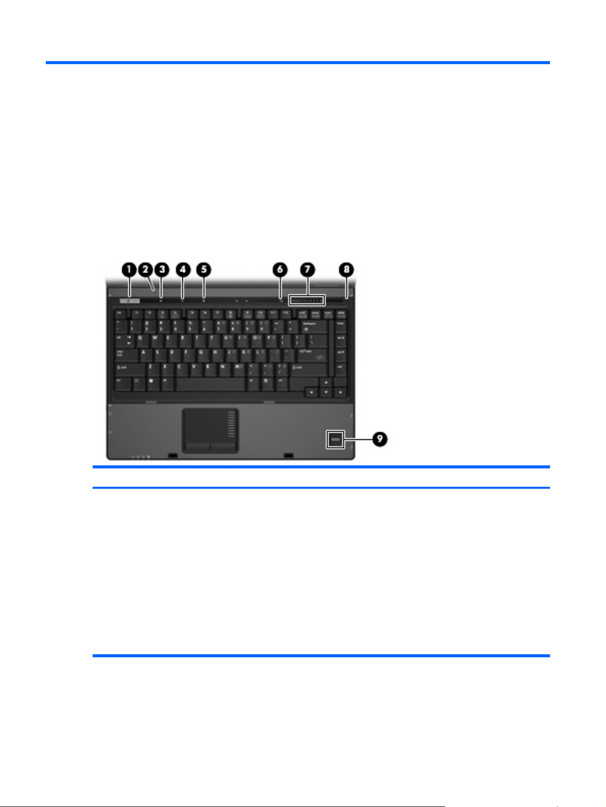
Buttons, switches, and fingerprint reader
Item Component Function
(1) Power button
10 Chapter 2 External component identification
When the computer is off, press the button to turn on the
●
computer.
When the computer is on, press the button to shut down the
●
computer.
When the computer is in the Sleep state (Windows Vista)
●
or in Standby (Windows XP), press the button briefly to exit
Sleep or Standby.
When the computer is in Hibernation, press the button
●
briefly to exit Hibernation.
If the computer has stopped responding and Windows®
shutdown procedures are ineffective, press and hold the power
button for at least 5 seconds to turn off the computer.
Page 19

Item Component Function
To learn more about power settings, follow these steps:
In Windows Vista, select Start > Control Panel > System
●
and Maintenance > Power Options.
In Windows XP, select Start > Control Panel >
●
Performance and Maintenance > Power Options.
(2) Internal display switch Turns off the display if the display is closed while the power is
on.
(3) Info button (select models only) Launches Info Center, which enables you to open various
software solutions.
(4) Wireless button Turns the wireless feature on or off, but does not establish a
wireless connection.
NOTE: A wireless network must be set up in order to establish
a wireless connection.
(5) Presentation button (select models only) Starts the presentation feature.
(6) Volume mute button (select models only) Mutes and restores speaker sound.
(7) Volume scroll zone (select models only) Adjusts speaker volume. Slide your finger to the left to decrease
volume and to the right to increase volume. You can also tap the
minus sign on the scroll zone to decrease volume, or tap the plus
sign on the scroll zone to increase volume.
(8) Internal microphone (select models only) Records sound.
(9) Fingerprint reader (select models only) Allows a fingerprint logon to Windows, instead of a password
logon.
Top components 11
Page 20
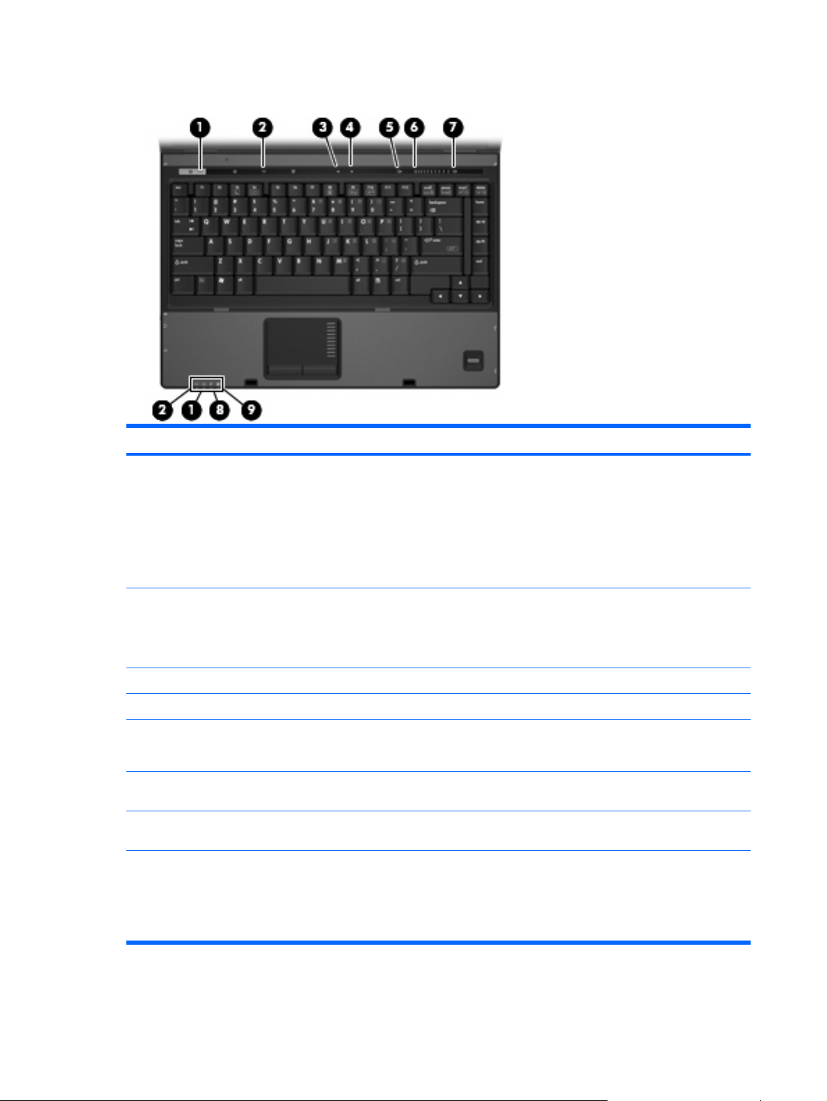
Lights
Item Component Function
(1) Power lights (2)
(2) Wireless lights (2)
(3) Caps lock light On: Caps lock is on.
(4) Num lock light On: Num lock is on or the embedded numeric keypad is enabled.
(5) Volume mute light (select models only)
(6) Volume down light (select models only) Blinking: The volume scroll zone is being used to decrease
(7) Volume up light (select models only) Blinking: The volume scroll zone is being used to increase
(8) Battery light
On: The computer is on.
●
Blinking: The computer is in the Sleep state (Windows
●
Vista) or in Standby (Windows XP).
Blinking rapidly: An AC adapter with a higher power rating
●
should be connected.
Off: The computer is off or in Hibernation.
●
On: An integrated wireless device, such as a wireless local
●
area network (WLAN) device, a wireless wide-area network
(WWAN) device, and/or a Bluetooth device is turned on.
Off: All wireless devices are turned off.
●
Off: Computer sound is turned on.
●
On: Computer sound is turned off.
●
speaker volume.
speaker volume.
Amber: A battery is charging.
●
12 Chapter 2 External component identification
Green: A battery is close to full charge capacity.
●
Blinking amber: A battery that is the only available power
●
source has reached a low battery level. When the battery
Page 21
Item Component Function
reaches a critical battery level, the battery light begins
blinking rapidly.
Off: If the computer is plugged into an external power
●
source, the light turns off when all batteries in the computer
are fully charged. If the computer is not plugged into an
external power source, the light stays off until the battery
reaches a low battery level.
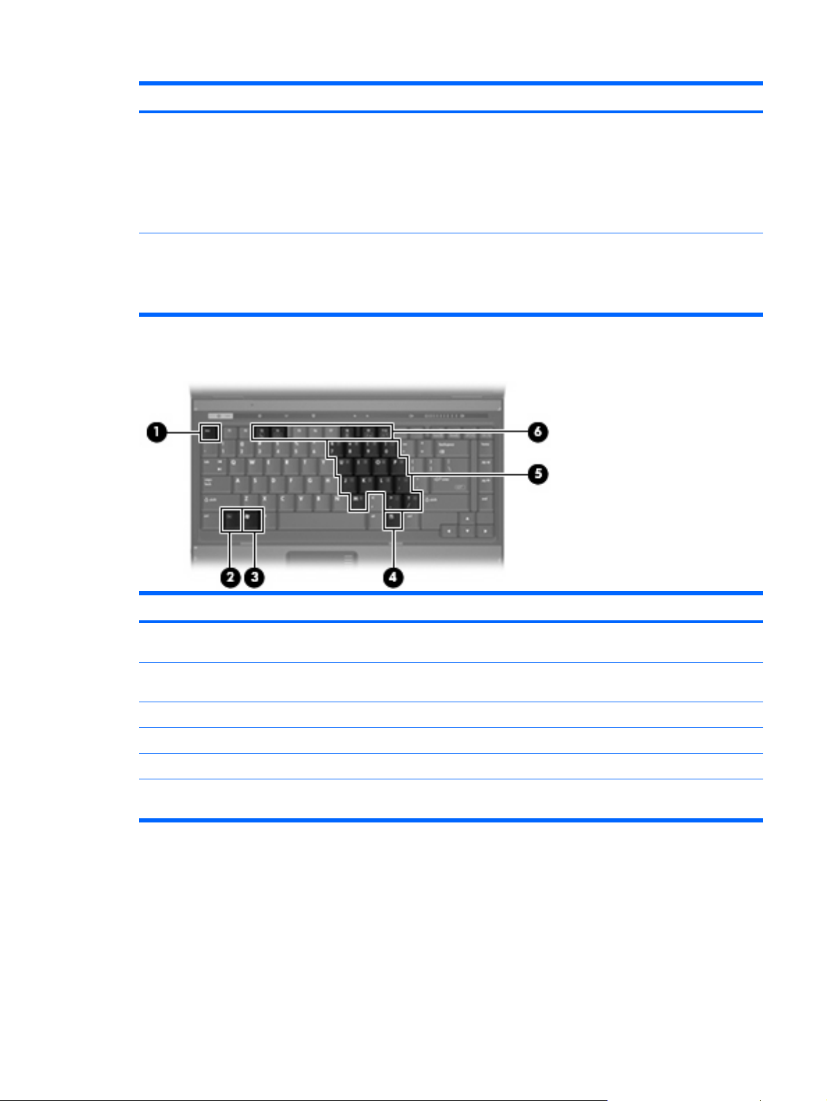
Keys
(9) Drive light
Item Component Function
(1) esc key Displays system information when pressed in combination with
Blinking green: The hard drive or optical drive is being
●
accessed.
Amber: HP 3D DriveGuard has temporarily parked the
●
internal hard drive.
the fn key.
(2) fn key Executes frequently used system functions when pressed in
combination with a function key or the esc key.
(3) Windows logo key Displays the Windows Start menu.
(4) Windows applications key Displays a shortcut menu for items beneath the pointer.
(5) Embedded numeric keypad keys Can be used like the keys on an external numeric keypad.
(6) Function keys Execute frequently used system functions when pressed in
combination with the fn key.
Top components 13
Page 22
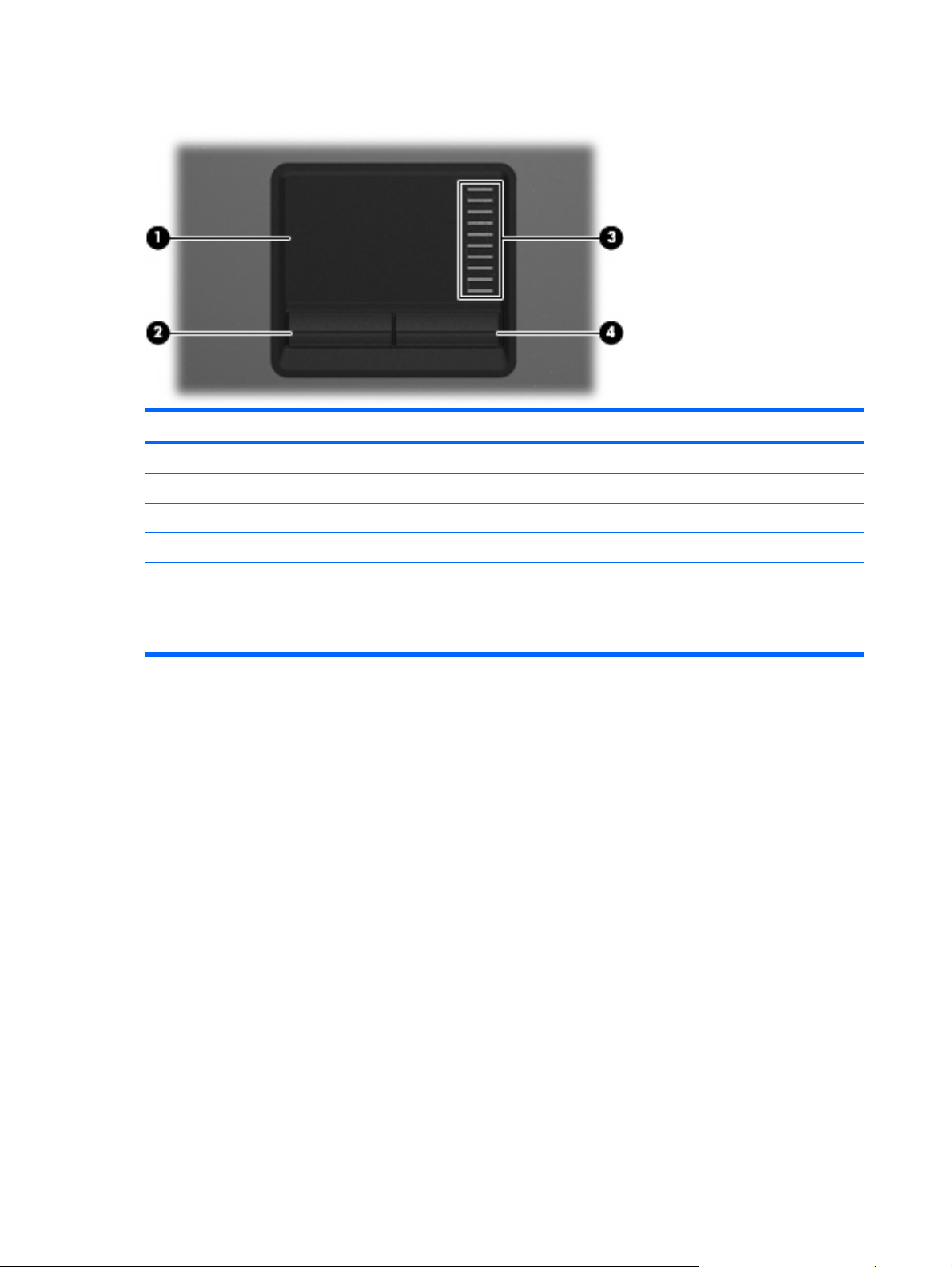
TouchPad
Item Component Function
(1) TouchPad* Moves the pointer and selects or activates items on the screen.
(2) Left TouchPad button* Functions like the left button on an external mouse.
(3) TouchPad scroll zone Scrolls up or down.
(4) Right TouchPad button* Functions like the right button on an external mouse.
*This table describes factory settings. View or change pointing device preferences as follows:
In Windows Vista, select Start > Control Panel > Hardware and Sound > Mouse.
●
In Windows XP, select Start > Control Panel > Printers and Other Hardware > Mouse
●
14 Chapter 2 External component identification
Page 23

Front components
Item Component Function
(1) Wireless light
(2) Power light
(3) Battery light
(4) Drive light
On: An integrated wireless device, such as a WLAN device,
●
a WWAN device, and/or a Bluetooth device, is turned on.
Off: All wireless devices are turned off.
●
On: The computer is on.
●
Blinking: The computer is in the Sleep state (Windows
●
Vista) or in Standby (Windows XP).
Blinking rapidly: An AC adapter with a higher power rating
●
should be connected.
Off: The computer is off or in Hibernation.
●
Amber: A battery is charging.
●
Green: A battery is close to full charge capacity.
●
Blinking amber: A battery that is the only available power
●
source has reached a low battery level. When the battery
reaches a critical battery level, the battery light begins
blinking rapidly.
Off: If the computer is plugged into an external power
●
source, the light turns off when all batteries in the computer
are fully charged. If the computer is not plugged into an
external power source, the light stays off until the battery
reaches a low battery level.
Blinking green: The hard drive or optical drive is being
●
accessed.
Amber (select models only): HP 3D DriveGuard has
●
temporarily parked the hard drive.
(5) Display release latch Opens the computer.
(6) Speakers Produce sound.
Front components 15
Page 24
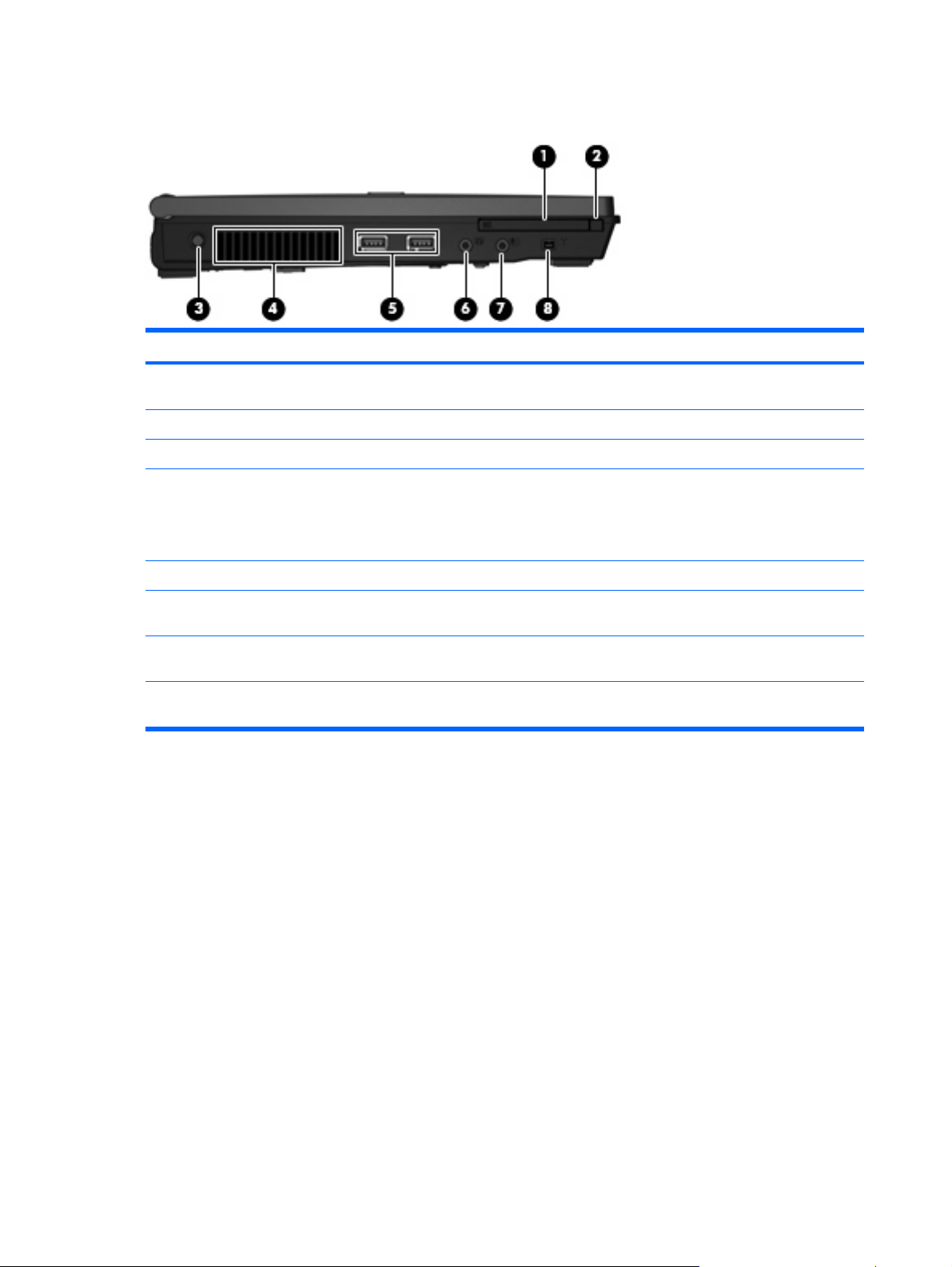
Left-side components
Item Component Function
(1) PC Card slot Supports optional Type I or Type II 32–bit (CardBus) or 16–bit
(2) PC Card eject button Ejects a PC Card from the PC Card slot.
(3) Power connector Connects an AC adapter.
(4) Vent Enables airflow to cool internal components.
(5) USB ports (2) Connect optional USB devices.
PC Cards.
NOTE: The computer fan starts up automatically to cool
internal components and prevent overheating. It is normal for the
internal fan to cycle on and off during routine operation.
(6) Audio-out (headphone) jack Produces sound when connected to optional powered stereo
speakers, headphones, ear buds, a headset, or television audio.
(7) Audio-in (microphone) jack Connects an optional computer headset microphone, stereo
array microphone, or monaural microphone.
(8) 1394 port (select models only) Connects an optional IEEE 1394 or 1394a device, such as a
camcorder.
16 Chapter 2 External component identification
Page 25
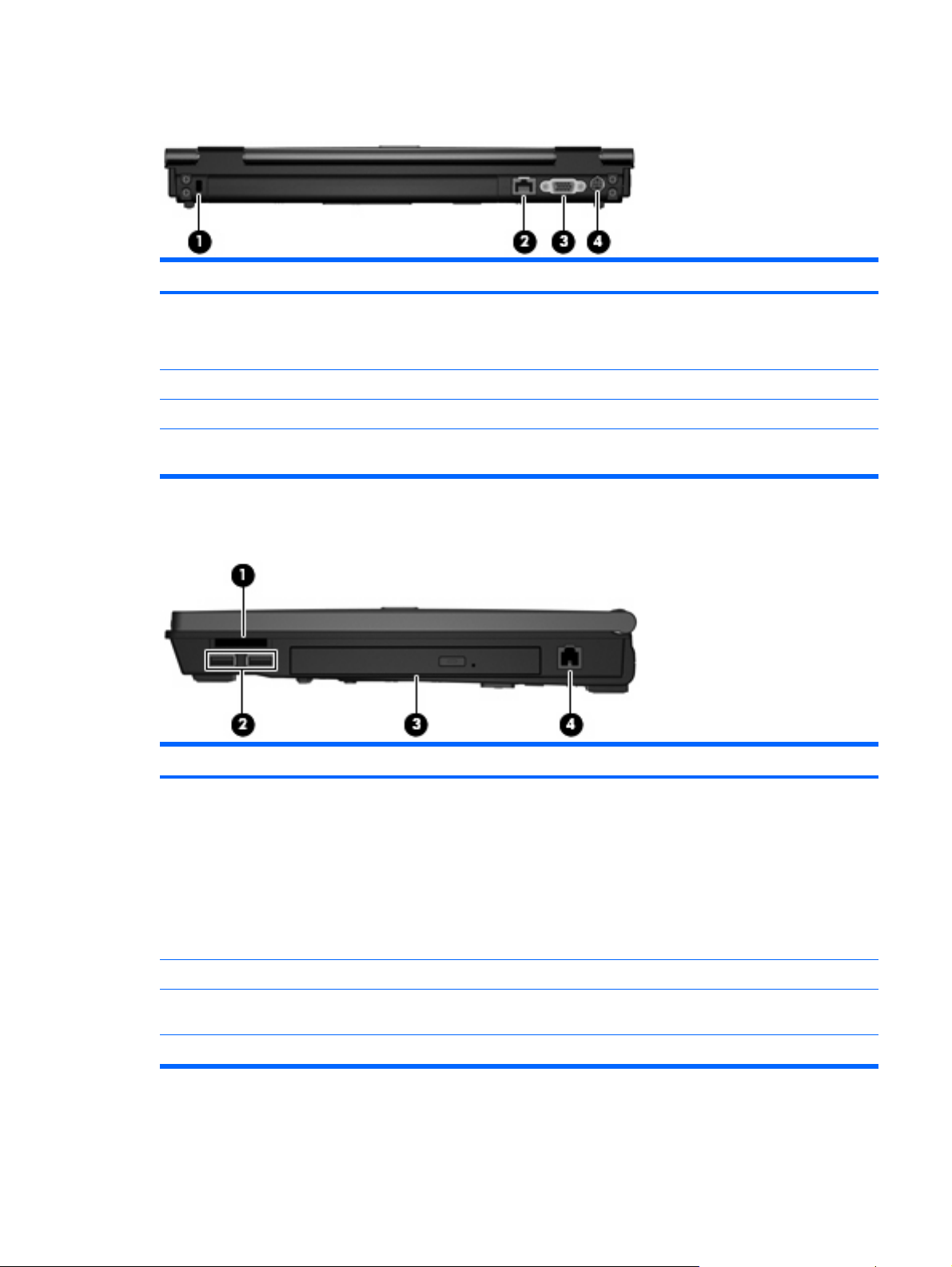
Rear components
Item Component Function
(1) Security cable slot Attaches an optional security cable to the computer.
(2) RJ-45 (network) jack Connects a network cable.
(3) External monitor port Connects an external VGA monitor or projector.
(4) S-Video-out jack Connects an optional S-Video device such as a television, VCR,
Right-side components
NOTE: The security cable is designed to act as a deterrent, but
it may not prevent the computer from being mishandled or stolen.
camcorder, overhead projector, or video capture card.
Item Component Function
(1) Media Card Reader (select models only)
(2) USB ports (2) (select models only) Connect optional USB devices.
(3) Optical drive Reads optical discs, and, on select models, also writes to optical
(4) RJ-11 (modem) jack Connects a modem cable.
Secure Digital (SD) Memory Card
●
MultiMediaCard (MMC)
●
Memory Stick (MS)
●
Memory Stick Pro (MSP)
●
Memory Stick Duo Adapter
●
xD-Picture Card (XD)
●
discs.
Rear components 17
Page 26
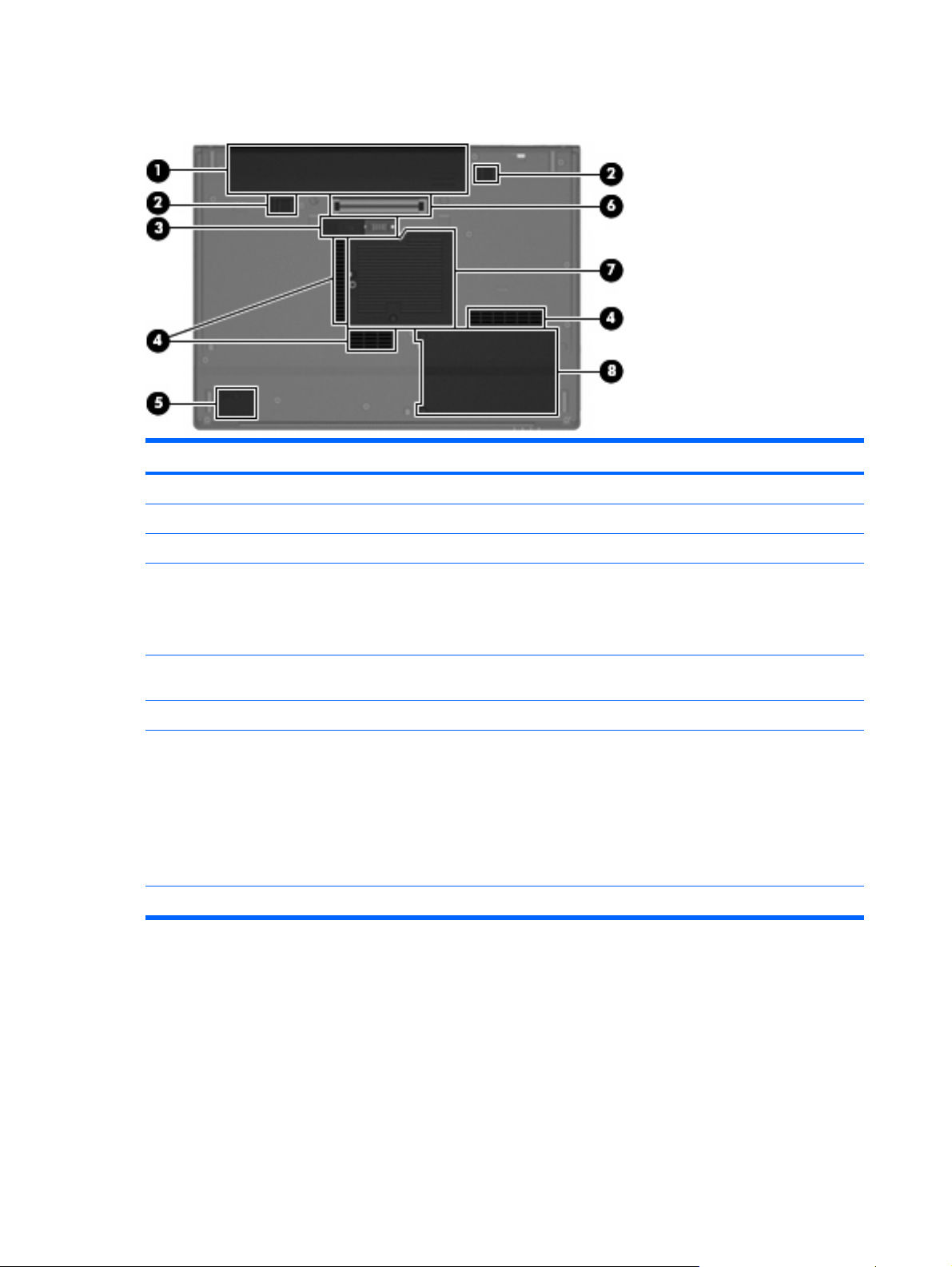
Bottom components
Item Component Function
(1) Battery bay Holds the battery.
(2) Battery release latches Releases the battery from the battery bay.
(3) Accessory battery connector Connects an optional accessory battery.
(4) Vents (3) Enable airflow to cool internal components.
NOTE: The computer fan starts up automatically to cool
internal components and prevent overheating. It is normal for the
internal fan to cycle on and off during routine operation.
(5) Bluetooth module compartment (select models
only)
(6) Docking connector (select models only) Connects an optional docking device.
(7) Memory/WLAN module compartment Contains the memory module slot and the WLAN module slot.
(8) Hard drive bay Holds the hard drive.
Contains a Bluetooth device.
CAUTION: To prevent an unresponsive system, replace the
wireless module only with a wireless module authorized for use
in the computer by the governmental agency that regulates
wireless devices in your country or region. If you replace the
module and then receive a warning message, remove the
module to restore computer functionality, and then contact
technical support through Help and Support.
18 Chapter 2 External component identification
Page 27
3 Illustrated parts catalog
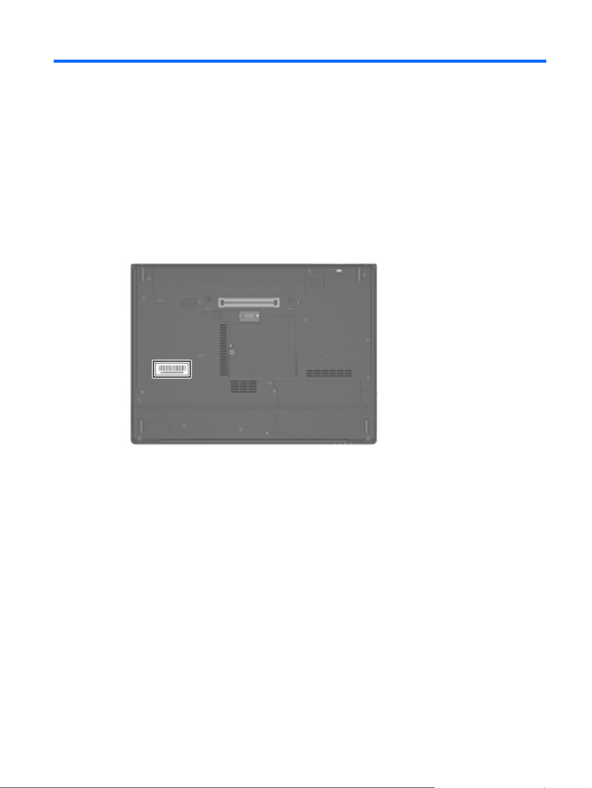
Serial number location
When ordering parts or requesting information, provide the computer serial number and model number
located on the bottom of the computer.
Serial number location 19
Page 28
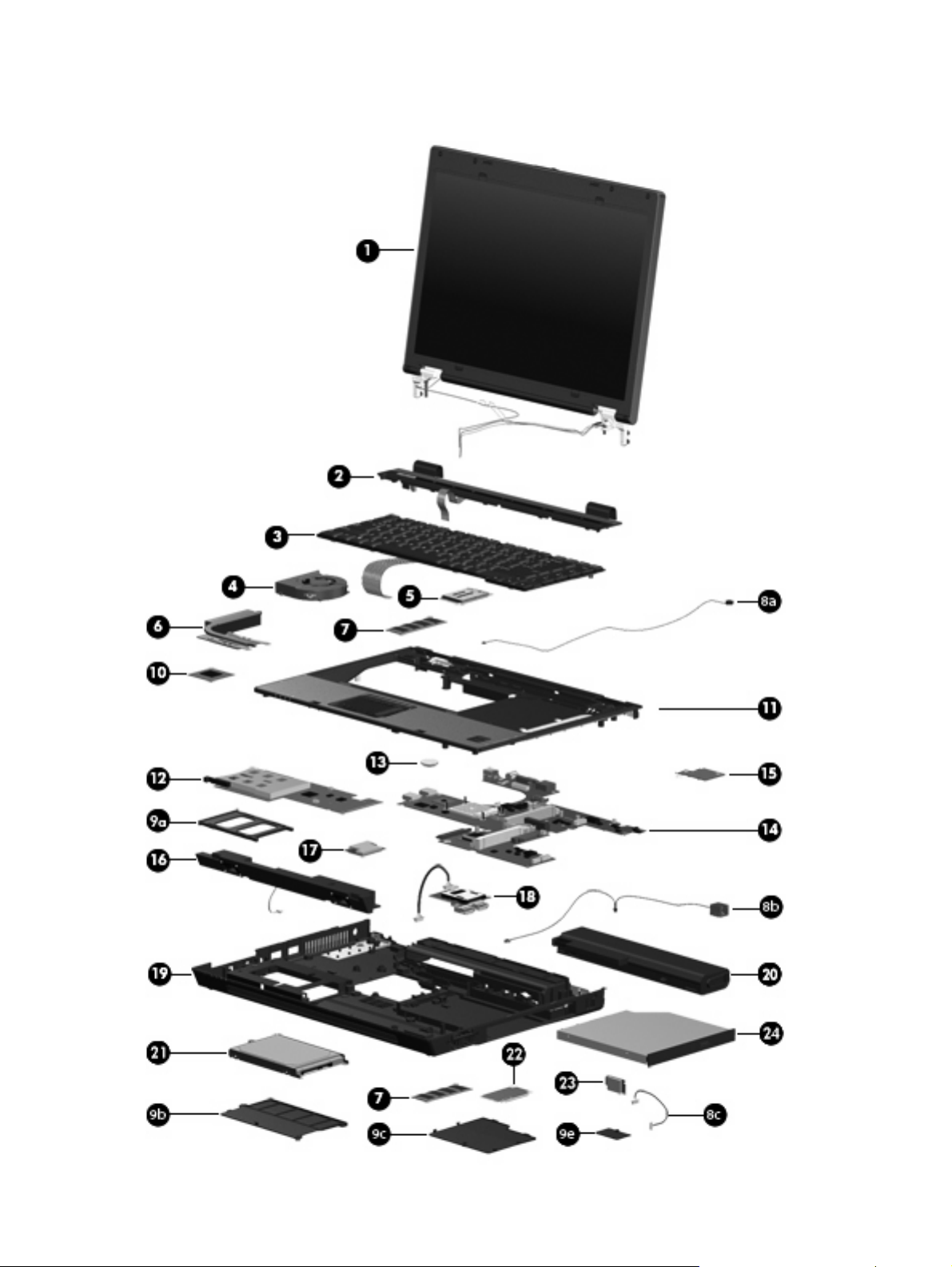
Computer major components
20 Chapter 3 Illustrated parts catalog
Page 29

Item Description Spare part number
(1) Display assemblies
14.1-inch, WXGA display assembly for use only with HP Compaq 6515b computer models
with WWAN capability
14.1-inch, WXGA, BrightView display assembly for use only with HP Compaq 6515b
computer models without WWAN capability
14.1-inch, WXGA display assembly for use only with HP Compaq 6515b computer models
without WWAN capability
14.1-inch, WXGA display assembly for use with HP Compaq 6510b computer models with
WWAN capability
14.1-inch, WXGA display assembly for use with HP Compaq 6510b computer models
without WWAN capability
Display assembly internal components
Display bezel 447205-001
14.1-inch, WXGA display panel for use with computer models with WWAN capability 446916-001
14.1-inch, WXGA display panel for use with computer models without WWAN capability 446914-001
14.1-inch, WXGA, BrightView display panel for use with computer models without WWAN
capability
Display inverter (includes 2-sided tape) 446870-001
Display left and right hinges 447204-001
Display enclosure 450067-001
443895-001
443894-001
443893-001
449823-001
449822-001
446915-001
(2) Switch cover (includes power button board and cable and LED board and cable) 447203-001
(3) Keyboards
Belgium 443922-181
Brazil 443922-201
The Czech Republic 443922-221
Denmark 443922-081
France 443922-051
French Canada 443922-121
Germany 443922-041
Greece 443922-DJ1
Hungary 443922-211
Iceland 443922-DD1
International 443922-A41
Israel 443922-BB1
Italy 443922-061
Japan 443922-291
Korea 443922-AD1
Computer major components 21
Page 30

Item Description Spare part number
Latin America 443922-161
The Netherlands 443922-B31
Norway 443922-091
Portugal 443922-131
Russia 443922-251
Saudi Arabia 443922-171
Slovakia 443922-231
Slovenia 443922-BA1
Spain 443922-071
Sweden 443922-B71
Switzerland 443922-BG1
Taiwan 443922-AB1
Thailand 443922-281
Turkey 443922-141
The United Kingdom 443922-031
The United States 443922-001
(4) Fan 443917-001
(5) WWAN modules
EVDO WWAN module for use in all countries and regions except Japan and Asia/Pacific 399440-001
Vodafone HSPDA WWAN module 448672-002
Cingular HSPDA WWAN module 448673-002
(6) Heat sinks (include thermal material)
For use with HP Compaq 6515b computer models 443912-001
For use with HP Compaq 6510b computer models 446920-001
Thermal Material Kits (not illustrated)
For use in all countries and regions except Japan and Asia/Pacific 413706-001
For use Japan and Asia/Pacific countries and regions 445853-001
(7) Memory modules (667-MHz, PC2-5300, 1-DIMM)
2048-MB 417506-001
1024-MB 414046-001
512-MB 414045-001
Cable Kit (see Cable Kit on page 29 for more Cable Kit spare part information): 443887-001
(8a) Microphone (includes receiver and cable)
(8b) Modem module cable (includes RJ-11 connector and cable)
22 Chapter 3 Illustrated parts catalog
Page 31

Item Description Spare part number
(8c) Bluetooth module cable
Plastics Kit (see Plastics Kit on page 28 for more Plastics Kit spare part information): 443905-001
(9a) PC Card slot bezel
(9b) Hard drive cover (includes 2 captive screws, secured by C-clips)
(9c) Memory/WLAN module compartment cover (includes 1 captive screw, secured by a C-clip)
(9d) Bluetooth module compartment cover (includes 1 captive screw, secured by a C-clip)
Display bezel rubber screw covers (6 covers in 2 sizes; not illustrated)
Base enclosure rubber screw covers (2 covers; not illustrated)
Computer feet (8 feet in 2 sizes; not illustrated)
(10) Processors (include thermal material)
Processors for use with HP Compaq 6515b computer models in all countries and regions except Japan and Asia/
Pacific:
Processors for use with HP Compaq 6515b computer models in Japan and Asia/Pacific countries and regions:
AMD Turion TL-64 (2.2-GHz, 1 MB of L2 cache)
●
AMD Turion MK-38 (2.2-GHz, 512 KB of L2 cache)
●
AMD Turion TL-60 (2.0-GHz, 1 MB of L2 cache)
●
AMD Turion TL-56 (1.8-GHz, 1 MB of L2 cache)
●
AMD Turion TL-52 (1.6-GHz, 1 MB of L2 cache)
●
AMD Turion TL-50 (1.6-GHz, 1 MB of L2 cache)
●
Mobile AMD Sempron 3800+ (2.2-GHz, 256 KB of L2 cache)
●
Mobile AMD Sempron 3600+ (2.0-GHz, 256 KB of L2 cache)
●
Mobile AMD Sempron 3500+ (1.8-GHz, 512 KB of L2 cache)
●
Mobile AMD Sempron 3400+ (1.8-GHz, 256 KB of L2 cache)
●
AMD Turion TL-60 (2.0-GHz, 1 MB of L2 cache)
●
AMD Turion TL-56 (1.8-GHz, 1 MB of L2 cache)
●
AMD Turion TL-52 (1.6-GHz, 1 MB of L2 cache)
●
Mobile AMD Sempron 3500+ (1.8-GHz, 512 KB of L2 cache)
●
Mobile AMD Sempron 3400+ (1.8-GHz, 256 KB of L2 cache)
●
443913-001
446045-001
430876-001
430875-001
430874-001
450940-001
450939-001
443916-001
430872-001
430871-001
443892-001
443891-001
443890-001
443915-001
443914-001
Processors for use with HP Compaq 6510b computer models:
(11) Top cover (includes TouchPad, TouchPad cable, and fingerprint reader) 443921-001
(12) PC Card/audio board assembly 443889-001
Intel Core Duo T7700 2.4-GHz with 4 MB of L2 cache
●
Intel Core Duo T7500 2.2-GHz with 4 MB of L2 cache
●
Intel Core Duo T7300 2.0-GHz with 4 MB of L2 cache
●
Intel Core Duo T7100 1.8-GHz with 2 MB of L2 cache
●
446894-001
446893-001
446892-001
446891-001
Computer major components 23
Page 32

Item Description Spare part number
(13) RTC battery 449137-001
(14) System boards
For use with HP Compaq 6515b computer models with WWAN capability (includes WWAN
module slot)
443896-001
For use with HP Compaq 6515b computer models without WWAN capability (does not
include WWAN module slot)
For use with HP Compaq 6510b computer models with WWAN capability (includes WWAN
module slot)
For use with HP Compaq 6510b computer models without WWAN capability (does not
include WWAN module slot)
(15) SIM slot board (for use with computer models with WWAN capability) 443907-001
(16) Speaker assembly 443909-001
(17) Modem modules (include modem module cable)
For use in all countries and regions except Australia and New Zealand 441074-001
For use only in Australia and New Zealand 441074-011
(18) Media Card Reader/USB connector board 443883-001
(19) Base enclosure (includes 8 rubber feet, not illustrated) 443886-001
(20) Batteries
6-cell, 2.55-Ah, 55-Wh, Li-ion battery 443885-001
6-cell, 2.20-Ah, 47-Wh, Li-ion battery 443884-001
(21) Hard drives (include hard drive bracket and connector)
160-GB, 5400-rpm 443920-001
443898-001
446905-001
446904-001
120-GB, 5400-rpm 443919-001
80-GB, 7200-rpm 445939-001
80-GB, 5400-rpm 443918-001
(22) WLAN modules
802.11a/b/g/n Broadcom WLAN modules for use with all computer models:
For use in Canada, the Cayman Islands, Guam, Puerto Rico, the United States, and
●
the Virgin Islands
For use in Afghanistan, Albania, Algeria, Andorra, Angola, Antigua & Barbuda,
●
Argentina, Armenia, Aruba, Australia, Austria, Azerbaijan, the Bahamas, Bahrain,
Bangladesh, Barbados, Belgium, Belize, Benin, Bermuda, Bhutan, Bolivia, Bosnia &
Herzegovina, Botswana, Brazil, the British Virgin Islands, Brunei, Bulgaria, Burkina
Faso, Burundi, Cameroon, Cape Verde, the Central African Republic, Chad, Chile,
China, Colombia, Comoros, Congo, Costa Rica, Croatia, Cyprus, the Czech Republic,
Denmark, Djibouti, Dominica, the Dominican Republic, East Timor, Ecuador, Egypt, El
Salvador, Equitorial Guinea, Eritrea, Estonia, Ethiopia, Fiji, Finland, France, French
Guiana, Gabon, Gambia, Georgia, Germany, Ghana, Gibraltar, Greece, Grenada,
Guadeloupe, Guatemala, Guinea, Guinea-Bissa, Guyana, Haiti, Honduras, Hong
Kong, Hungary, Iceland, India, Ireland, Italy, the Ivory Coast, Jamaica, Jordan,
Kazakhstan, Kenya, Kiribati, Kyrgyzstan, Laos, Latvia, Lebanon, Lesotho, Liberia,
Liechtenstein, Lithuania, Luxembourg, Macedonia, Madagascar, Malawi,
24 Chapter 3 Illustrated parts catalog
441530-001
441530-002
Page 33

Item Description Spare part number
the Maldives, Mali, Malta, the Marshall Islands, Martinique, Mauritania, Mauritius,
Mexico, Micronesia, Monaco, Mongolia, Montenegro, Morocco, Mozambique,
Namibia, Nauru, Nepal, the Nether Antilles, the Netherlands, New Zealand, Nicaragua,
Niger, Nigeria, Norway, Oman, Pakistan, Palau, Panama, Papua New Guinea,
Paraguay, Peru, the Philippines, Poland, Portugal, Puerto Rico, the Republic of
Moldova, Romania, Russia, Rwanda, Samoa, San Marino, Sao Tome & Principe Saudi
Arabia, Senegal, Serbia and Montenegro, the Seychelles, Sierra Leone, Singapore,
Slovakia, Slovenia, the Solomon Islands, Somalia, South Africa, Spain, Sri Lanka, St.
Kitts & Nevis, St. Lucia, St. Vincent & Gren, Suriname, Swaziland, Sweden,
Switzerland, Taiwan, Tajikistan, Tanzania, Togo, Tonga, Trinidad & Tobago, Tunisia,
Turkey, Turkmenistan, Tuvalu, Uganda, the United Arab Emirates, the United
Kingdom, Uruguay, Uzbekistan, Vanuatu, Venezuela, Vietnam, Yemen, Zaire, Zambia,
and Zimbabwe
802.11a/b/g/n Intel WLAN module for use with HP Compaq 6510b computer models:
802.11a/b/g Broadcom WLAN modules for use with all computer models:
For use in Israel and Japan
●
For use in Antigua and Barbuda, Argentina, Aruba, the Bahamas, Barbados, Bermuda,
●
Brunei, Canada, the Cayman Islands, Chile, Colombia, Costa Rica, the Dominican
Republic, Ecuador, El Salvador, Guam, Guatemala, Haiti, Honduras, Hong Kong,
India, Indonesia, Malaysia, Mexico, Panama, Paraguay, Peru, Saudi Arabia, Taiwan,
Uruguay, the United States, Venezuela, and Vietnam
For use in Austria, Azerbaijan, Bahrain, Belgium, Brazil, Bulgaria, Croatia, Cyprus, the
●
Czech Republic, Denmark, Egypt, Estonia, Finland, France, Georgia, Germany,
Greece, Hungary, Iceland, Ireland, Israel, Italy, Latvia, Lebanon, Liechtenstein,
Lithuania, Luxembourg, Malta, Monaco, the Netherlands, Norway, Oman, the
Philippines, Poland, Portugal, Qatar, Romania, Russia, Serbia and Montenegro,
Singapore, Slovakia, Slovenia, South Africa, Spain, Sri Lanka, Sweden, Switzerland,
Turkey, Ukraine, the United Kingdom, and Uzbekistan
For use in Australia, New Zealand, Pakistan, the People's Republic of China, and South
●
Korea
For use in Japan
●
For use in Canada, the Cayman Islands, Guam, Puerto Rico, the United States, and
●
the Virgin Islands
For use in Afghanistan, Albania, Algeria, Andorra, Angola, Antigua & Barbuda,
●
Argentina, Armenia, Aruba, Australia, Austria, Azerbaijan, the Bahamas, Bahrain,
Bangladesh, Barbados, Belarus, Belgium, Belize, Benin, Bermuda, Bhutan, Bolivia,
Bosnia & Herzegovina, Botswana, Brazil, the British Virgin Islands, Brunei, Bulgaria,
Burkina Faso, Burundi, Cameroon, Cape Verde, the Central African Republic, Chad,
Chile, China, Colombia, Comoros, Congo, Costa Rica, Croatia, Cyprus, the Czech
Republic, Denmark, Djibouti, Dominica, the Dominican Republic, East Timor, Ecuador,
Egypt, El Salvador, Equitorial Guinea, Eritrea, Estonia, Ethiopia, Fiji, Finland, France,
French Guiana, Gabon, Gambia, Georgia, Germany, Ghana, Gibraltar, Greece,
Grenada, Guadeloupe, Guatemala, Guinea, Guinea-Bissa, Guyana, Haiti, Honduras,
Hong Kong, Hungary, Iceland, India, Ireland, Israel, Italy, the Ivory Coast, Jamaica,
Jordan, Kazakhstan, Kenya, Kiribati, Kyrgyzstan, Laos, Latvia, Lebanon, Lesotho,
Liberia, Liechtenstein, Lithuania, Luxembourg, Macedonia, Madagascar, Malawi,
Malaysia, the Maldives, Mali, Malta, the Marshall Islands, Martinique, Mauritania,
Mauritius, Mexico, Micronesia, Monaco, Mongolia, Montenegro, Morocco,
Mozambique, Namibia, Nauru, Nepal, the Nether Antilles, the Netherlands, New
Zealand, Nicaragua, Niger, Nigeria, Norway, Oman, Pakistan, Palau, Panama, Papua
New Guinea, Paraguay, Peru, the Philippines, Poland, Portugal, the Republic of
Moldova, Romania, Russia, Rwanda, Samoa, San Marino, Sao Tome & Principe,
Saudi Arabia, Senegal, Serbia and Montenegro, the Seychelles, Sierra Leone,
Singapore, Slovakia, Slovenia, the Solomon Islands, Somalia, South Africa, South
Korea, Spain, Sri Lanka, St. Kitts & Nevis, St. Lucia, St. Vincent & Gren, Suriname,
441530-291
441086-001
441086-002
441086-003
441086-291
441075-001
441075-002
Computer major components 25
Page 34

Item Description Spare part number
Swaziland, Sweden, Switzerland, Taiwan, Tajikistan, Tanzania, Togo, Tonga, Trinidad
& Tobago, Tunisia, Turkey, Turkmenistan, Tuvalu, Uganda, Ukraine, the United Arab
Emirates, the United Kingdom, Uruguay, Uzbekistan, Vanuatu, Venezuela, Vietnam,
Yemen, Zaire, Zambia, and Zimbabwe
802.11a/b/g Intel WLAN modules for use with HP Compaq 6510b computer models:
802.11b/g Broadcom WLAN modules for use with all computer models:
For use in Japan
●
For use in Antigua and Barbuda, Argentina, Australia, the Bahamas, Barbados, Brunei,
●
Canada, Chile, the Dominican Republic, Guam, Guatemala, Hong Kong, India,
Indonesia, Malaysia, Mexico, New Zealand, Panama, Paraguay, Saudi Arabia,
Taiwan, the United States, and Vietnam
For use in Aruba, Austria, Azerbaijan, Bahrain, Belgium, Bermuda, Brazil, Bulgaria,
●
the Cayman Islands, Colombia, Croatia, Cyprus, the Czech Republic, Denmark, Egypt,
El Salvador, Estonia, Finland, France, Georgia, Germany, Greece, Hungary, Iceland,
Ireland, Italy, Jordan, Latvia, Lebanon, Liechtenstein, Lithuania, Luxembourg, Malta,
Monaco, the Netherlands, Norway, Oman, the Philippines, Poland, Portugal, Romania,
Russia, Serbia and Montenegro, Singapore, Slovakia, Slovenia, South Africa, Spain,
Sri Lanka, Sweden, Switzerland, Turkey, the United Kingdom, and Uzbekistan
For use in Ecuador, Haiti, Honduras, Pakistan, the People's Republic of China, Peru,
●
Qatar, South Korea, Uruguay, and Venezuela
For use in Japan
●
For use in Canada, the Cayman Islands, Guam, Puerto Rico, the United States, and
●
the U.S. Virgin Islands
For use in Afghanistan, Albania, Algeria, Andorra, Angola, Antigua & Barbuda,
●
Argentina, Armenia, Aruba, Australia, Austria, Azerbaijan, the Bahamas, Bahrain,
Bangladesh, Barbados, Belarus, Belgium, Belize, Benin, Bermuda, Bhutan, Bolivia,
Bosnia & Herzegovina, Botswana, Brazil, the British Virgin Islands, Brunei, Bulgaria,
Burkina Faso, Burundi, Cambodia, Cameroon, Cape Verde, the Central African
Republic, Chad, Chile, China, Colombia, Comoros, Congo, Costa Rica, Croatia,
Cyprus, the Czech Republic, Denmark, Djibouti, Dominica, the Dominican Republic,
East Timor, Ecuador, Egypt, El Salvador, Equitorial Guinea, Eritrea, Estonia, Ethiopia,
Fiji, Finland, France, French Guiana, Gabon, Gambia, Georgia, Germany, Ghana,
Gibraltar, Greece, Grenada, Guadeloupe, Guatemala, Guinea, Guinea-Bissa,
Guyana, Haiti, Honduras, Hong Kong, Hungary, Iceland, India, Indonesia, Ireland,
Israel, Italy, the Ivory Coast, Jamaica, Jordan, Kazakhstan, Kenya, Kiribati, Kuwait,
Kyrgyzstan, Laos, Latvia, Lebanon, Lesotho, Liberia, Liechtenstein, Lithuania,
Luxembourg, Macedonia, Madagascar, Malawi, Malaysia, the Maldives, Mali, Malta,
the Marshall Islands, Martinique, Mauritania, Mauritius, Mexico, Micronesia, Monaco,
Mongolia, Montenegro, Morocco, Mozambique, Namibia, Nauru, Nepal, the Nether
Antilles, the Netherlands, New Zealand, Nicaragua, Niger, Nigeria, Norway, Oman,
Pakistan, Palau, Panama, Papua New Guinea, Paraguay, Peru, the Philippines,
Poland, Portugal, Qatar, the Republic of Moldova, Romania, Russia, Rwanda, Samoa,
San Marino, Sao Tome & Principe, Saudi Arabia, Senegal, Serbia and Montenegro,
the Seychelles, Sierra Leone, Singapore, Slovakia, Slovenia, the Solomon Islands,
Somalia, South Africa, South Korea, Spain, Sri Lanka, St. Kitts & Nevis, St. Lucia, St.
Vincent & Gren, Suriname, Swaziland, Sweden, Switzerland, Taiwan, Tajikistan,
Tanzania, Thailand, Togo, Tonga, Trinidad & Tobago, Tunisia, Turkey, Turkmenistan,
Tuvalu, Uganda, Ukraine, the United Arab Emirates, the United Kingdom, Uruguay,
Uzbekistan, Vanuatu, Venezuela, Vietnam, Yemen, Zaire, Zambia, and Zimbabwe
441075-291
407575-001
407575-002
407575-003
407575-291
441090-001
441090-002
802.11b/g Broadcom WLAN module for use with HP Compaq 6510b computer models in
For use in Japan
●
Japan
26 Chapter 3 Illustrated parts catalog
441090-291
409280-004
Page 35

Item Description Spare part number
(23) Bluetooth modules–Bluetooth module cable not included. This cable is included in the Cable Kit, spare part number
443887-001. See
For use in all countries and regions except Japan and Asia/Pacific 398393-002
For use in Japan and Asia/Pacific countries and regions 450066-001
(24) Optical drives (include bezel and optical drive bracket)
DVD±RW and CD-RW Super Multi Double-Layer Combo Drive with LightScribe 443903-001
DVD±RW and CD-RW Super Multi Double-Layer Combo Drive 443904-001
DVD/CD-RW Combo Drive 443901-001
DVD-ROM drive 443902-001
Cable Kit on page 29 for more Cable Kit spare part information.
Computer major components 27
Page 36

Plastics Kit
Item Description Spare part number
Plastics Kit 443905-001
(1) PC Card slot bezel
(2) Hard drive cover (includes 2 captive screws, secured by C-clips)
(3) Memory/WLAN module compartment cover (includes 1 captive screw, secured by a C-clip)
(4) Bluetooth module compartment cover (includes 1 captive screw, secured by a C-clip)
(5) Computer feet (4 large, 4 small)
Display bezel rubber screw covers (6 covers in 2 sizes; not illustrated)
28 Chapter 3 Illustrated parts catalog
Page 37

Cable Kit
Item Description Spare part number
Cable Kit 443887-001
(1) Modem module cable (includes RJ-11 connector and cable)
(2) Microphone (includes receiver and cable)
(3) Bluetooth module cable
Cable Kit 29
Page 38

Mass storage devices
Item Description Spare part number
(1) Hard drives (include frame and connector)
160-GB, 5400-rpm 443920-001
120-GB, 5400-rpm 443919-001
80-GB, 7200-rpm 445939-001
80-GB, 5400-rpm 443918-001
(2) Optical drives (include bezel and optical drive bracket)
DVD±RW and CD-RW Super Multi Double-Layer Combo Drive with LightScribe 443903-001
DVD±RW and CD-RW Super Multi Double-Layer Combo Drive 443904-001
DVD/CD-RW Combo Drive 443901-001
DVD-ROM drive 443902-001
30 Chapter 3 Illustrated parts catalog
Page 39

Miscellaneous parts
Description Spare part number
AC adapters
90-watt PFC AC adapter for use in Africa, Europe, and the Middle East
90-watt PFC AC adapter for use in North America 391173-001
Power cords:
Australia
Brazil 246959-201
Denmark 246959-081
Europe, the Middle East, and Africa 246959-021
Israel 246959-BB1
Italy 246959-061
Japan 246959-291
Korea 246959-AD1
Switzerland 246959-AG1
The United Kingdom 246959-031
The United States 246959-001
Screw Kit
Hex HM5.0×9.0 screw lock
●
416421-021
246959-011
443906-001
Phillips PM3.0×3.0 screw
●
Phillips PM2.5×13.0 captive screw
●
Black Phillips PM2.5×8.0 captive screw
●
Silver Phillips PM2.5×8.0 captive screw
●
Phillips PM2.5×8.0 screw
●
Phillips PM2.5×5.0 screw
●
Phillips PM2.5×3.0 screw
●
Phillips PM2.0×6.0 screw
●
Phillips PM2.0×5.0 captive screw
●
Phillips PM2.0×3.0 screw
●
Torx T8M2.5×17.0 screw
●
Torx T8M2.5×9.0 screw
●
Torx T8M2.5×7.0 screw
●
Torx T8M2.5×6.0 screw
●
Smart card reader module 443908-001
Miscellaneous parts 31
Page 40

Sequential part number listing
Spare part
number
246959-001 Power cord for use in the United States
246959-011 Power cord for use in Australia
246959-021 Power cord for use in Europe, the Middle East, and Africa
246959-031 Power cord for use in the United Kingdom
246959-061 Power cord for use in Italy
246959-081 Power cord for use in Denmark
246959-201 Power cord for use in Brazil
246959-291 Power cord for use in Japan
246959-AD1 Power cord for use in Korea
246959-AG1 Power cord for use in Switzerland
246959-BB1 Power cord for use in Israel
391173-001 90-watt PFC AC adapter for use in North America
398393-002 Bluetooth module for use in all countries and regions except Japan and Asia/Pacific–Bluetooth module cable
Description
not included. This cable is included in the Cable Kit, spare part number. See
Cable Kit spare part information.
Cable Kit on page 29 for more
399440-001 EVDO WWAN module
407575-001 802.11a/b/g Intel WLAN module for use with HP Compaq 6510b computer models in Antigua and Barbuda,
Argentina, Australia, the Bahamas, Barbados, Brunei, Canada, Chile, the Dominican Republic, Guam,
Guatemala, Hong Kong, India, Indonesia, Malaysia, Mexico, New Zealand, Panama, Paraguay, Saudi Arabia,
Taiwan, the United States, and Vietnam
407575-002 802.11a/b/g Intel WLAN module for use with HP Compaq 6510b computer models in Aruba, Austria,
Azerbaijan, Bahrain, Belgium, Bermuda, Brazil, Bulgaria, the Cayman Islands, Colombia, Croatia, Cyprus, the
Czech Republic, Denmark, Egypt, El Salvador, Estonia, Finland, France, Georgia, Germany, Greece,
Hungary, Iceland, Ireland, Italy, Jordan, Latvia, Lebanon, Liechtenstein, Lithuania, Luxembourg, Malta,
Monaco, the Netherlands, Norway, Oman, the Philippines, Poland, Portugal, Romania, Russia, Serbia and
Montenegro, Singapore, Slovakia, Slovenia, South Africa, Spain, Sri Lanka, Sweden, Switzerland, Turkey, the
United Kingdom, and Uzbekistan
407575-003 802.11a/b/g Intel WLAN module for use with HP Compaq 6510b computer models in Ecuador, Haiti, Honduras,
407575-291 802.11a/b/g Intel WLAN module for use with HP Compaq 6510b computer models in Japan
409280-004 802.11b/g Broadcom WLAN module for use with HP Compaq 6510b computer models in Thailand
413706-001 Thermal Material Kit for use in all countries and regions except Japan and Asia/Pacific
414045-001 512-MB memory module (667-MHz, PC-5300, 1-DIMM)
414046-001 1024-MB memory module (667-MHz, PC-5300, 1-DIMM)
416421-021 90-watt PFC AC adapter for use in Africa, Europe, and the Middle East
417506-001 2048-MB memory module (667-MHz, PC-5300, 1-DIMM)
Pakistan, the People's Republic of China, Peru, Qatar, South Korea, Uruguay, and Venezuela
430871-001 Mobile AMD Sempron 3400+ 1.8-GHz processor for use with HP Compaq 6515b computer models in all
countries and regions except Japan and Asia/Pacific (256 KB of L2 cache)
32 Chapter 3 Illustrated parts catalog
Page 41

Spare part
number
Description
430872-001 Mobile AMD Sempron 3500+ 1.8-GHz processor for use with HP Compaq 6515b computer models in all
430874-001 AMD Turion TL-52 1.6-GHz processor for use with HP Compaq 6515b computer models in all countries and
430875-001 AMD Turion TL-56 1.8-GHz processor for use with HP Compaq 6515b computer models in all countries and
430876-001 AMD Turion TL-60 2.0-GHz processor for use with HP Compaq 6515b computer models in all countries and
441074-001 Modem module for use in all countries and regions except Australia and New Zealand (includes modem
441074-011 Modem module for use only in Australia and New Zealand (includes modem module cable)
441075-001 802.11a/b/g WLAN module for use in Canada, the Cayman Islands, Guam, Puerto Rico, the United States,
441075-002 802.11a/b/g WLAN module for use in Afghanistan, Albania, Algeria, Andorra, Angola, Antigua & Barbuda,
countries and regions except Japan and Asia/Pacific (256 KB of L2 cache)
regions except Japan and Asia/Pacific (1 MB of L2 cache)
regions except Japan and Asia/Pacific (1 MB of L2 cache)
regions except Japan and Asia/Pacific (1 MB of L2 cache)
module cable)
and the Virgin Islands
Argentina, Armenia, Aruba, Australia, Austria, Azerbaijan, the Bahamas, Bahrain, Bangladesh, Barbados,
Belarus, Belgium, Belize, Benin, Bermuda, Bhutan, Bolivia, Bosnia & Herzegovina, Botswana, Brazil, the
British Virgin Islands, Brunei, Bulgaria, Burkina Faso, Burundi, Cameroon, Cape Verde, the Central African
Republic, Chad, Chile, China, Colombia, Comoros, Congo, Costa Rica, Croatia, Cyprus, the Czech Republic,
Denmark, Djibouti, Dominica, the Dominican Republic, East Timor, Ecuador, Egypt, El Salvador, Equitorial
Guinea, Eritrea, Estonia, Ethiopia, Fiji, Finland, France, French Guiana, Gabon, Gambia, Georgia, Germany,
Ghana, Gibraltar, Greece, Grenada, Guadeloupe, Guatemala, Guinea, Guinea-Bissa, Guyana, Haiti,
Honduras, Hong Kong, Hungary, Iceland, India, Ireland, Israel, Italy, the Ivory Coast, Jamaica, Jordan,
Kazakhstan, Kenya, Kiribati, Kyrgyzstan, Laos, Latvia, Lebanon, Lesotho, Liberia, Liechtenstein, Lithuania,
Luxembourg, Macedonia, Madagascar, Malawi, Malaysia, the Maldives, Mali, Malta, the Marshall Islands,
Martinique, Mauritania, Mauritius, Mexico, Micronesia, Monaco, Mongolia, Montenegro, Morocco,
Mozambique, Namibia, Nauru, Nepal, the Nether Antilles, the Netherlands, New Zealand, Nicaragua, Niger,
Nigeria, Norway, Oman, Pakistan, Palau, Panama, Papua New Guinea, Paraguay, Peru, the Philippines,
Poland, Portugal, the Republic of Moldova, Romania, Russia, Rwanda, Samoa, San Marino, Sao Tome &
Principe, Saudi Arabia, Senegal, Serbia and Montenegro, the Seychelles, Sierra Leone, Singapore, Slovakia,
Slovenia, the Solomon Islands, Somalia, South Africa, South Korea, Spain, Sri Lanka, St. Kitts & Nevis, St.
Lucia, St. Vincent & Gren, Suriname, Swaziland, Sweden, Switzerland, Taiwan, Tajikistan, Tanzania, Togo,
Tonga, Trinidad & Tobago, Tunisia, Turkey, Turkmenistan, Tuvalu, Uganda, Ukraine, the United Arab
Emirates, the United Kingdom, Uruguay, Uzbekistan, Vanuatu, Venezuela, Vietnam, Yemen, Zaire, Zambia,
and Zimbabwe
441075-291 802.11a/b/g WLAN module for use in Japan
441082-001 802.11a/b/g Intel WLAN module for use with HP Compaq 6510b computer models in Antigua & Barbuda,
Argentina, Aruba, the Bahamas, Barbados, Bermuda, Brunei, Canada, the Cayman Islands, Chile, Colombia,
Costa Rica, the Dominican Republic, Ecuador, El Salvador, Guam, Guatemala, Haiti, Honduras, Hong Kong,
India, Indonesia, Malaysia, Mexico, Panama, Paraguay, Peru, Saudi Arabia, Taiwan, the United States,
Uruguay, Venezuela, Vietnam
441082-002 802.11a/b/g Intel WLAN module for use with HP Compaq 6510b computer models in Austria, Azerbaijan,
Bahrain, Belgium, Brazil, Bulgaria, Croatia, Cyprus, the Czech Republic, Denmark, Egypt, Estonia, Finland,
France, Georgia, Germany, Greece, Hungary, Iceland, Ireland, Israel, Italy, Latvia, Lebanon, Liechtenstein,
Lithuania, Luxembourg, Malta, Monaco, the Netherlands, Norway, Oman, the Philippines, Poland, Portugal,
Qatar, Romania, Russia, Serbia and Montenegro, Singapore, Slovakia, Slovenia, South Africa, Spain, Sri
Lanka, Sweden, Switzerland, Turkey, Ukraine, the United Kingdom, and Uzbekistan
441082-003 802.11a/b/g Intel WLAN module for use with HP Compaq 6510b computer models in Australia, New Zealand,
Pakistan, the People's Republic of China, and South Korea
441082-291 802.11a/b/g Intel WLAN module for use with HP Compaq 6510b computer models in Japan
441086-001 802.11a/b/g/n Intel WLAN module for use with HP Compaq 6510b computer models in Antigua and Barbuda,
Argentina, Aruba, the Bahamas, Barbados, Bermuda, Brunei, Canada, the Cayman Islands, Chile, Colombia,
Sequential part number listing 33
Page 42

Spare part
number
441086-002 802.11a/b/g/n Intel WLAN module for use with HP Compaq 6510b computer models in Austria, Azerbaijan,
441086-003 802.11a/b/g/n Intel WLAN module for use in with HP Compaq 6510b computer models in Australia, New
441086-291 802.11a/b/g/n Intel WLAN module for use with HP Compaq 6510b computer models in Japan
441090-001 802.11b/g Broadcom WLAN module for use in Canada, the Cayman Islands, Guam, Puerto Rico, the United
441090-002 802.11b/g Broadcom WLAN module for use in Afghanistan, Albania, Algeria, Andorra, Angola, Antigua &
Description
Costa Rica, the Dominican Republic, Ecuador, El Salvador, Guam, Guatemala, Haiti, Honduras, Hong Kong,
India, Indonesia, Malaysia, Mexico, Panama, Paraguay, Peru, Saudi Arabia, Taiwan, Uruguay, the United
States, Venezuela, and Vietnam
Bahrain, Belgium, Brazil, Bulgaria, Croatia, Cyprus, the Czech Republic, Denmark, Egypt, Estonia, Finland,
France, Georgia, Germany, Greece, Hungary, Iceland, Ireland, Israel, Italy, Latvia, Lebanon, Liechtenstein,
Lithuania, Luxembourg, Malta, Monaco, the Netherlands, Norway, Oman, the Philippines, Poland, Portugal,
Qatar, Romania, Russia, Serbia and Montenegro, Singapore, Slovakia, Slovenia, South Africa, Spain, Sri
Lanka, Sweden, Switzerland, Turkey, Ukraine, the United Kingdom, and Uzbekistan
Zealand, Pakistan, the People's Republic of China, and South Korea
States, and the Virgin Islands
Barbuda, Argentina, Armenia, Aruba, Australia, Austria, Azerbaijan, the Bahamas, Bahrain, Bangladesh,
Barbados, Belarus, Belgium, Belize, Benin, Bermuda, Bhutan, Bolivia, Bosnia & Herzegovina, Botswana,
Brazil, the British Virgin Islands, Brunei, Bulgaria, Burkina Faso, Burundi, Cameroon, Cape Verde, the Central
African Republic, Chad, Chile, China, Colombia, Comoros, Congo, Costa Rica, Croatia, Cyprus, the Czech
Republic, Denmark, Djibouti, Dominica, the Dominican Republic, East Timor, Ecuador, Egypt, El Salvador,
Equitorial Guinea, Eritrea, Estonia, Ethiopia, Fiji, Finland, France, French Guiana, Gabon, Gambia, Georgia,
Germany, Ghana, Gibraltar, Greece, Grenada, Guadeloupe, Guatemala, Guinea, Guinea-Bissa, Guyana,
Haiti, Honduras, Hong Kong, Hungary, Iceland, India, Ireland, Israel, Italy, the Ivory Coast, Jamaica, Jordan,
Kazakhstan, Kenya, Kiribati, Kyrgyzstan, Laos, Latvia, Lebanon, Lesotho, Liberia, Liechtenstein, Lithuania,
Luxembourg, Macedonia, Madagascar, Malawi, Malaysia, the Maldives, Mali, Malta, the Marshall Islands,
Martinique, Mauritania, Mauritius, Mexico, Micronesia, Monaco, Mongolia, Montenegro, Morocco,
Mozambique, Namibia, Nauru, Nepal, the Nether Antilles, the Netherlands, New Zealand, Nicaragua, Niger,
Nigeria, Norway, Oman, Pakistan, Palau, Panama, Papua New Guinea, Paraguay, Peru, the Philippines,
Poland, Portugal, the Republic of Moldova, Romania, Russia, Rwanda, Samoa, San Marino, Sao Tome &
Principe, Saudi Arabia, Senegal, Serbia and Montenegro, the Seychelles, Sierra Leone, Singapore, Slovakia,
Slovenia, the Solomon Islands, Somalia, South Africa, South Korea, Spain, Sri Lanka, St. Kitts & Nevis, St.
Lucia, St. Vincent & Gren, Suriname, Swaziland, Sweden, Switzerland, Taiwan, Tajikistan, Tanzania, Togo,
Tonga, Trinidad & Tobago, Tunisia, Turkey, Turkmenistan, Tuvalu, Uganda, Ukraine, the United Arab
Emirates, the United Kingdom, Uruguay, Uzbekistan, Vanuatu, Venezuela, Vietnam, Yemen, Zaire, Zambia,
and Zimbabwe
441090-291 802.11b/g Broadcom WLAN module for use in Japan
441530-001 802.11b/g Broadcom WLAN module for use in Canada, the Cayman Islands, Guam, Puerto Rico, the United
States, and the U.S. Virgin Islands
441530-002 802.11b/g Broadcom WLAN module for use in Afghanistan, Albania, Algeria, Andorra, Angola, Antigua &
Barbuda, Argentina, Armenia, Aruba, Australia, Austria, Azerbaijan, the Bahamas, Bahrain, Bangladesh,
Barbados, Belarus, Belgium, Belize, Benin, Bermuda, Bhutan, Bolivia, Bosnia & Herzegovina, Botswana,
Brazil, the British Virgin Islands, Brunei, Bulgaria, Burkina Faso, Burundi, Cambodia, Cameroon, Cape Verde,
the Central African Republic, Chad, Chile, China, Colombia, Comoros, Congo, Costa Rica, Croatia, Cyprus,
the Czech Republic, Denmark, Djibouti, Dominica, the Dominican Republic, East Timor, Ecuador, Egypt, El
Salvador, Equitorial Guinea, Eritrea, Estonia, Ethiopia, Fiji, Finland, France, French Guiana, Gabon, Gambia,
Georgia, Germany, Ghana, Gibraltar, Greece, Grenada, Guadeloupe, Guatemala, Guinea, Guinea-Bissa,
Guyana, Haiti, Honduras, Hong Kong, Hungary, Iceland, India, Indonesia, Ireland, Israel, Italy, the Ivory Coast,
Jamaica, Jordan, Kazakhstan, Kenya, Kiribati, Kuwait, Kyrgyzstan, Laos, Latvia, Lebanon, Lesotho, Liberia,
Liechtenstein, Lithuania, Luxembourg, Macedonia, Madagascar, Malawi, Malaysia, the Maldives, Mali, Malta,
the Marshall Islands, Martinique, Mauritania, Mauritius, Mexico, Micronesia, Monaco, Mongolia, Montenegro,
Morocco, Mozambique, Namibia, Nauru, Nepal, the Nether Antilles, the Netherlands, New Zealand,
Nicaragua, Niger, Nigeria, Norway, Oman, Pakistan, Palau, Panama, Papua New Guinea, Paraguay, Peru,
the Philippines, Poland, Portugal, Qatar, the Republic of Moldova, Romania, Russia, Rwanda, Samoa, San
Marino, Sao Tome & Principe, Saudi Arabia, Senegal, Serbia and Montenegro, the Seychelles, Sierra Leone,
Singapore, Slovakia, Slovenia, the Solomon Islands, Somalia, South Africa, South Korea, Spain, Sri Lanka,
34 Chapter 3 Illustrated parts catalog
Page 43

Spare part
number
441530-291 802.11b/g Broadcom WLAN module for use in Japan
443883-001 Media Card Reader/USB connector board
443884-001 6-cell, 2.20-Ah, 47-Wh battery
443885-001 6-cell, 2.55-Ah, 55-Wh battery
443886-001 Base enclosure (includes 6 rubber feet)
443887-001 Cable Kit
443889-001 PC Card/audio board assembly
Description
St. Kitts & Nevis, St. Lucia, St. Vincent & Gren, Suriname, Swaziland, Sweden, Switzerland, Taiwan, Tajikistan,
Tanzania, Thailand, Togo, Tonga, Trinidad & Tobago, Tunisia, Turkey, Turkmenistan, Tuvalu, Uganda,
Ukraine, the United Arab Emirates, the United Kingdom, Uruguay, Uzbekistan, Vanuatu, Venezuela, Vietnam,
Yemen, Zaire, Zambia, and Zimbabwe
443890-001 AMD Turion TL-52 1.6-GHz processor for use with HP Compaq 6515b computer models only in Japan and
443891-001 AMD Turion TL-56 1.8-GHz processor for use with HP Compaq 6515b computer models only in Japan and
443892-001 AMD Turion TL-64 2.0-GHz processor for use with HP Compaq 6515b computer models only in Japan and
443893-001 14.1-inch WXGA display assembly for use only with HP Compaq 6515b computer models without WWAN
443894-001 14.1-inch WXGA, BrightView display assembly for use only with HP Compaq 6515b computer models without
443895-001 14.1-inch WXGA display assembly for use only with HP Compaq 6515b computer models with WWAN
443896-001 System board for use with HP Compaq 6515b computer models with WWAN capability (includes WWAN
443898-001 System board for use with HP Compaq 6515b computer models without WWAN capability (does not include
443901-001 DVD/CD-RW Combo Drive
443902-001 DVD-ROM drive
443903-001 DVD±RW and CD-RW Super Multi Double-Layer Combo Drive with LightScribe
443904-001 DVD±RW and CD-RW Super Multi Double-Layer Combo Drive
Asia/Pacific countries and regions (1 MB of L2 cache)
Asia/Pacific countries and regions (1 MB of L2 cache)
Asia/Pacific countries and regions (1 MB of L2 cache)
capability
WWAN capability
capability
module slot)
WWAN module slot)
443905-001 Plastics Kit (see Plastics Kit on page 28 for more Plastics Kit spare part information)
443906-001 Screw Kit
443907-001 SIM slot board (for use with computer models with WWAN capability)
443908-001 Smart card reader module
443909-001 Speaker assembly
443912-001 Heat sink for use with HP Compaq 6515b computer models (includes thermal material)
443913-001 AMD Turion TL-64 2.2-GHz processor for use with HP Compaq 6515b computer models in all countries and
regions except Japan and Asia/Pacific (1 MB of L2 cache)
Sequential part number listing 35
Page 44

Spare part
number
Description
443914-001 Mobile AMD Sempron 3400+ 1.8-GHz processor for use with HP Compaq 6515b computer models in Japan
443915-001 Mobile AMD Sempron 3500+ 1.8-GHz processor for use with HP Compaq 6515b computer models in Japan
443916-001 Mobile AMD Sempron 3600+ 2.0-GHz processor for use with HP Compaq 6515b computer models in all
443917-001 Fan
443918-001 80-GB, 5400-rpm hard drive
443919-001 120-GB, 5400-rpm hard drive
443920-001 160-GB, 5400-rpm hard drive
443921-001 Top cover (includes TouchPad, TouchPad cable, and fingerprint reader)
443922-001 Keyboard for use in the United States
443922-031 Keyboard for use in the United Kingdom
443922-041 Keyboard for use in Germany
443922-051 Keyboard for use in France
443922-061 Keyboard for use in Italy
443922-071 Keyboard for use in Spain
443922-081 Keyboard for use in Denmark
and Asia/Pacific countries and regions (256 KB of L2 cache)
and Asia/Pacific countries and regions (512 KB of L2 cache)
countries and regions except Japan and Asia/Pacific (256 KB of L2 cache)
443922-091 Keyboard for use in Sweden
443922-121 Keyboard for use in French Canada
443922-131 Keyboard for use in Portugal
443922-141 Keyboard for use in Turkey
443922-161 Keyboard for use in Latin America
443922-171 Keyboard for use in Saudi Arabia
443922-181 Keyboard for use in Belgium
443922-201 Keyboard for use in Brazil
443922-211 Keyboard for use in Hungary
443922-221 Keyboard for use in the Czech Republic
443922-231 Keyboard for use in Slovakia
443922-251 Keyboard for use in Russia
443922-281 Keyboard for use in Thailand
443922-291 Keyboard for use in Japan
443922-A41 Keyboard for use in
443922-AB1 Keyboard for use in Taiwan
443922-AD1 Keyboard for use in Korea
36 Chapter 3 Illustrated parts catalog
Page 45

Spare part
number
443922-B31 Keyboard for use in the Netherlands
443922-B71 Keyboard for use in Sweden and Finland
443922-BA1 Keyboard for use in Slovenia
443922-BB1 Keyboard for use in Israel
443922-BG1 Keyboard for use in Switzerland
443922-DD1 Keyboard for use in Iceland
443922-DJ1 Keyboard for use in Greece
445853-001 Thermal Material Kit for use in Japan and Asia/Pacific countries and regions
445939-001 80-GB, 7200-rpm hard drive
446045-001 AMD Turion MK-38 2.2-GHz processor for use with HP Compaq 6515b computer models in all countries and
446870-001 Display inverter (includes 2-sided tape)
446891-001 Intel Core Duo T7100 1.8-GHz processor with 2 MB of L2 cache for use with HP Compaq 6510b computer
446892-001 Intel Core Duo T7300 2.0-GHz processor with 4 MB of L2 cache for use with HP Compaq 6510b computer
Description
regions except Japan and Asia/Pacific (512 KB of L2 cache)
models
models
446893-001 Intel Core Duo T7500 2.2-GHz processor with 4 MB of L2 cache for use with HP Compaq 6510b computer
models
446894-001 Intel Core Duo T7700 2.4-GHz processor with 4 MB of L2 cache for use with HP Compaq 6510b computer
models
446904-001 System board for use with HP Compaq 6510b computer models without WWAN capability (does not include
WWAN module slot)
446905-001 System board for use with HP Compaq 6510b computer models with WWAN capability (includes WWAN
module slot)
446914-001 14.1-inch, WXGA display panel for use with HP Compaq 6510b computer models without WWAN capability
446915-001 14.1-inch, WXGA, BrightView display panel for use with HP Compaq 6510b computer models without WWAN
capability
446916-001 14.1-inch, WXGA display panel for use with HP Compaq 6510b computer models with WWAN capability
446920-001 Heat sink for use with HP Compaq 6510b computer models (includes thermal material)
447203-001 Switch cover (includes power button board and cable and LED board and cable)
447204-001 Display left and right hinges
447205-001 Display bezel
448672-002 Vodafone HSPDA WWAN module
448673-002 Cingular HSPDA WWAN module
449137-001 RTC battery
449822-001 14.1-inch, WXGA display assembly for use with HP Compaq 6510b computer models without WWAN
capability
449823-001 14.1-inch, WXGA display assembly for use with HP Compaq 6510b computer models with WWAN capability
Sequential part number listing 37
Page 46

Spare part
number
Description
450066-001 Bluetooth module for use in Japan and Asia/Pacific countries and regions–Bluetooth module cable not
included. This cable is included in the Cable Kit, spare part number 443887-001. See
for more Cable Kit spare part information.
450067-001 Display enclosure
450939-001 Mobile AMD Sempron 3800+ 2.2-GHz processor for use with HP Compaq 6515b computer models in all
countries and regions except Japan and Asia/Pacific (256 KB of L2 cache)
450940-001 AMD Turion TL-50 1.6-GHz processor for use with HP Compaq 6515b computer models in all countries and
regions except Japan and Asia/Pacific (1 MB of L2 cache)
Cable Kit on page 29
38 Chapter 3 Illustrated parts catalog
Page 47

4 Removal and replacement procedures
Preliminary replacement requirements
Tools required
You will need the following tools to complete the removal and replacement procedures:
Flat-bladed screwdriver
●
Hex 5.0-mm nutdriver
●
Magnetic screwdriver
●
Phillips P0 and P1 screwdrivers
●
Torx T8 screwdriver
●
Service considerations
The following sections include some of the considerations that you must keep in mind during
disassembly and assembly procedures.
NOTE: As you remove each subassembly from the computer, place the subassembly (and all
accompanying screws) away from the work area to prevent damage.
Plastic parts
Using excessive force during disassembly and reassembly can damage plastic parts. Use care when
handling the plastic parts. Apply pressure only at the points designated in the maintenance instructions.
Preliminary replacement requirements 39
Page 48

Cables and connectors
CAUTION: When servicing the computer, be sure that cables are placed in their proper locations
during the reassembly process. Improper cable placement can damage the computer.
Cables must be handled with extreme care to avoid damage. Apply only the tension required to unseat
or seat the cables during removal and insertion. Handle cables by the connector whenever possible. In
all cases, avoid bending, twisting, or tearing cables. Be sure that cables are routed in such a way that
they cannot be caught or snagged by parts being removed or replaced. Handle flex cables with extreme
care; these cables tear easily.
Drive handling
CAUTION: Drives are fragile components that must be handled with care. To prevent damage to the
computer, damage to a drive, or loss of information, observe these precautions:
Before removing or inserting a hard drive, shut down the computer. If you are unsure whether the
computer is off or in Hibernation, turn the computer on, and then shut it down through the operating
system.
Before handling a drive, be sure that you are discharged of static electricity. While handling a drive,
avoid touching the connector.
Before removing a diskette drive or optical drive, be sure that a diskette or disc is not in the drive and
be sure that the optical drive tray is closed.
Handle drives on surfaces covered with at least one inch of shock-proof foam.
Avoid dropping drives from any height onto any surface.
After removing a hard drive, an optical drive, or a diskette drive, place it in a static-proof bag.
Avoid exposing a hard drive to products that have magnetic fields, such as monitors or speakers.
Avoid exposing a drive to temperature extremes or liquids.
If a drive must be mailed, place the drive in a bubble pack mailer or other suitable form of protective
packaging and label the package “FRAGILE.”
40 Chapter 4 Removal and replacement procedures
Page 49

Grounding guidelines
Electrostatic discharge damage
Electronic components are sensitive to electrostatic discharge (ESD). Circuitry design and structure
determine the degree of sensitivity. Networks built into many integrated circuits provide some protection,
but in many cases, ESD contains enough power to alter device parameters or melt silicon junctions.
A discharge of static electricity from a finger or other conductor can destroy static-sensitive devices or
microcircuitry. Even if the spark is neither felt nor heard, damage may have occurred.
An electronic device exposed to ESD may not be affected at all and can work perfectly throughout a
normal cycle. Or the device may function normally for a while, then degrade in the internal layers,
reducing its life expectancy.
CAUTION: To prevent damage to the computer when you are removing or installing internal
components, observe these precautions:
Keep components in their electrostatic-safe containers until you area ready to install them.
Use nonmagnetic tools.
Before touching an electronic component, discharge static electricity by using the guidelines described
in this section.
Avoid touching pins, leads, and circuitry. Handle electronic components as little as possible.
If you remove a component, place it in an electrostatic-safe container.
The following table shows how humidity affects the electrostatic voltage levels generated by different
activities.
CAUTION: A product can be degraded by as little as 700 V.
Typical electrostatic voltage levels
Relative humidity
Event 10% 40% 55%
Walking across carpet 35,000 V 15,000 V 7,500 V
Walking across vinyl floor 12,000 V 5,000 V 3,000 V
Motions of bench worker 6,000 v 800 V 400 V
Removing DIPS from plastic tube 2,000 V 700 V 400 V
Removing DIPS from vinyl tray 11,500 V 4,000 V 2,000 V
Removing DIPS from Styrofoam 14,500 V 5,000 V 3,500 V
Removing bubble pack from PCB 26,500 V 20,000 V 7,000 V
Packing PCBs in foam-lined box 21,000 V 11,000 V 5,000 V
Preliminary replacement requirements 41
Page 50

Packaging and transporting guidelines
Follow these grounding guidelines when packaging and transporting equipment:
To avoid hand contact, transport products in static-safe tubes, bags, or boxes.
●
Protect ESD-sensitive parts and assemblies with conductive or approved containers or packaging.
●
Keep ESD-sensitive parts in their containers until the parts arrive at static-free workstations.
●
Place items on a grounded surface before removing items from their containers.
●
Always be properly grounded when touching a component or assembly.
●
Store reusable ESD-sensitive parts from assemblies in protective packaging or nonconductive
●
foam.
Use transporters and conveyors made of antistatic belts and roller bushings. Be sure that
●
mechanized equipment used for moving materials is wired to ground and that proper materials are
selected to avoid static charging. When grounding is not possible, use an ionizer to dissipate
electric charges.
Workstation guidelines
Follow these grounding workstation guidelines:
Cover the workstation with approved static-shielding material.
●
Use a wrist strap connected to a properly grounded work surface and use properly grounded tools
●
and equipment.
Use conductive field service tools, such as cutters, screwdrivers, and vacuums.
●
When fixtures must directly contact dissipative surfaces, use fixtures made only of static-safe
●
materials.
Keep the work area free of nonconductive materials, such as ordinary plastic assembly aids and
●
Styrofoam.
Handle ESD-sensitive components, parts, and assemblies by the case or PCM laminate. Handle
●
these items only at static-free workstations.
Avoid contact with pins, leads, or circuitry.
●
Turn off power and input signals before inserting or removing connectors or test equipment.
●
42 Chapter 4 Removal and replacement procedures
Page 51

Equipment guidelines
Grounding equipment must include either a wrist strap or a foot strap at a grounded workstation.
When seated, wear a wrist strap connected to a grounded system. Wrist straps are flexible straps
●
with a minimum of one megohm ±10% resistance in the ground cords. To provide proper ground,
wear a strap snugly against the skin at all times. On grounded mats with banana-plug connectors,
use alligator clips to connect a wrist strap.
When standing, use foot straps and a grounded floor mat. Foot straps (heel, toe, or boot straps)
●
can be used at standing workstations and are compatible with most types of shoes or boots. On
conductive floors or dissipative floor mats, use foot straps on both feet with a minimum of one
megohm resistance between the operator and ground. To be effective, the conductive strips must
be worn in contact with the skin.
The following grounding equipment is recommended to prevent electrostatic damage:
Antistatic tape
●
Antistatic smocks, aprons, and sleeve protectors
●
Conductive bins and other assembly or soldering aids
●
Nonconductive foam
●
Conductive tabletop workstations with ground cords of one megohm resistance
●
Static-dissipative tables or floor mats with hard ties to the ground
●
Field service kits
●
Static awareness labels
●
Material-handling packages
●
Nonconductive plastic bags, tubes, or boxes
●
Metal tote boxes
●
Electrostatic voltage levels and protective materials
●
The following table lists the shielding protection provided by antistatic bags and floor mats.
Material Use Voltage protection level
Antistatic plastic Bags 1,500 V
Carbon-loaded plastic Floor mats 7,500 V
Metallized laminate Floor mats 5,000 V
Preliminary replacement requirements 43
Page 52

Unknown user password
If the computer you are servicing has an unknown user password, follow these steps to clear the
password:
NOTE: These steps also clear CMOS.
1. Shut down the computer. If you are unsure whether the computer is off or in Hibernation, turn the
computer on, and then shut it down through the operating system.
2. Disconnect all external devices connected to the computer.
3. Disconnect the power from the computer by first unplugging the power cord from the AC outlet and
then unplugging the AC adapter from the computer.
4. Remove the battery (see
5. Remove the real-time clock (RTC) battery (see
6. Wait approximately 5 minutes.
7. Replace the RTC battery and reassemble the computer.
8. Connect AC power to the computer. Do not reinsert any batteries at this time.
9. Turn on the computer.
All passwords and all CMOS settings have been cleared.
Battery on page 46).
RTC battery on page 66).
44 Chapter 4 Removal and replacement procedures
Page 53

Component replacement procedures
This chapter provides removal and replacement procedures.
There are as many as 78 screws and screw locks, in 17 different sizes, that must be removed, replaced,
or loosened when servicing the computer. Make special note of each screw and screw lock size and
location during removal and replacement.
Serial number
Report the computer serial number to HP when requesting information or ordering spare parts. The
serial number is located on the bottom of the computer.
Component replacement procedures 45
Page 54

Battery
Description Spare part number
6-cell, 2.55-Ah, 55-Wh, Li-ion battery 443885-001
6-cell, 2.20-Ah, 47-Wh, Li-ion battery 443884-001
Before disassembling the computer, follow these steps:
1. Shut down the computer. If you are unsure whether the computer is off or in Hibernation, turn the
computer on, and then shut it down through the operating system.
2. Disconnect all external devices connected to the computer.
3. Disconnect the power from the computer by first unplugging the power cord from the AC outlet and
then unplugging the AC adapter from the computer.
Remove the battery:
1. Turn the computer upside down on a flat surface, with the battery bay toward you.
2. Slide the battery release latches (1) to release the battery.
3. Remove the battery (2).
Install the battery by inserting it into the battery bay until you hear a click.
46 Chapter 4 Removal and replacement procedures
Page 55
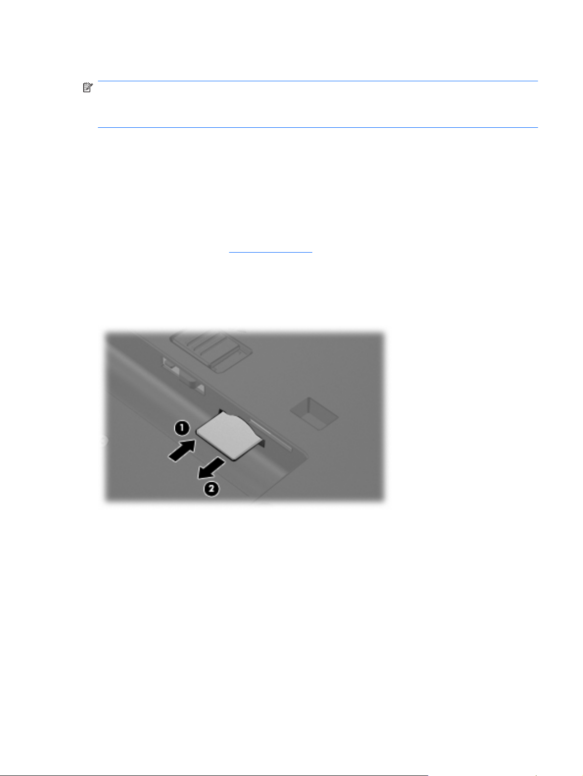
SIM
NOTE: This section applies only to computer models with WWAN capability.
NOTE: If there is a SIM inserted in the SIM slot, it must be removed before disassembling the
computer. Be sure the SIM is reinserted in the SIM slot after reassembling the computer.
Before removing the SIM, follow these steps:
1. Shut down the computer. If you are unsure whether the computer is off or in Hibernation, turn the
computer on, and then shut it down through the operating system.
2. Disconnect all external devices connected to the computer.
3. Disconnect the power from the computer by first unplugging the power cord from the AC outlet and
then unplugging the AC adapter from the computer.
4. Remove the battery (see
Remove the SIM:
1. Press in on the SIM (1). (The module is partially ejected from the SIM slot.)
2. Remove the SIM (2) from the SIM slot.
Reverse this procedure to install the SIM.
Battery on page 46).
Component replacement procedures 47
Page 56

Display inverter
NOTE: If it has been determined that the display inverter is the component that must be replaced to
complete the computer repair, the display assembly does not have to be removed. Follow the procedures
in this section to replace the display inverter. For information on replacing the display assembly and
display hinges, see
Description Spare part number
Display inverter (includes 2-sided tape) 446870-001
Before removing the display inverter, follow these steps:
1. Shut down the computer. If you are unsure whether the computer is off or in Hibernation, turn the
computer on, and then shut it down through the operating system.
2. Disconnect all external devices connected to the computer.
3. Disconnect the power from the computer by first unplugging the power cord from the AC outlet and
then unplugging the AC adapter from the computer.
Display assembly on page 75.
4. Remove the battery (see
Battery on page 46).
Remove the display inverter:
1. Turn the computer right-side up, with the front toward you.
2. Open the computer as far as it will open.
3. Remove the two rubber screw covers (1) on the bottom edge of the display bezel.
NOTE: The display bezel rubber screw covers are included in the Plastics Kit, spare part number
44305-001.
4. Remove the two Torx T8M2.5×7.0 screws (2) that secure the bottom edge of the display bezel to
the display enclosure.
5. Flex the inside edges of the left and right sides (1) and the bottom edge (2) of the display bezel
until the bezel disengages from the display enclosure.
48 Chapter 4 Removal and replacement procedures
Page 57

6. Release the bottom edge of the display bezel (3) from the display assembly.
7. Release the inverter (1) from the display enclosure as far as the cables attached to it allow.
8. Disconnect the display panel cable (2) and the backlight cable (3) from the display inverter.
9. Remove the display inverter.
Reverse this procedure to install the display inverter.
Component replacement procedures 49
Page 58

Hard drive
Description Spare part number
160-GB, 5400-rpm hard drive 443920-001
120-GB, 5400-rpm hard drive 443919-001
80-GB, 7200-rpm hard drive 445939-001
80-GB, 5400-rpm hard drive 443918-001
Before disassembling the computer, follow these steps:
1. Shut down the computer. If you are unsure whether the computer is off or in Hibernation, turn the
2. Disconnect all external devices connected to the computer.
3. Disconnect the power from the computer by first unplugging the power cord from the AC outlet and
computer on, and then shut it down through the operating system.
then unplugging the AC adapter from the computer.
4. Remove the battery (see
Battery on page 46).
Remove the hard drive:
1. Position the computer with the front toward you.
2. Loosen the two Phillips PM2.0×5.0 screws (1) that secure the hard drive cover to the computer.
3. Lift the left side of the hard drive cover (2), swing it to right, and remove the cover.
NOTE: The hard drive cover is included in the Plastics Kit, spare part number 443905-001.
4. Loosen the Phillips PM2.5×13.0 hard drive retention screw (1) that secures the hard drive to the
computer.
5. Grasp the Mylar tab (2) on the hard drive and pull the hard drive (3) to the right to disconnect it
from the system board.
50 Chapter 4 Removal and replacement procedures
Page 59

6. Remove the hard drive (4) from the hard drive bay.
7. If it is necessary to replace the hard drive bracket, remove the four Phillips PM3.0×3.0 hard drive
bracket screws (1) from each side of the hard drive.
8. Lift the bracket (2) straight up to remove it from the hard drive.
Reverse this procedure to reassemble and install the hard drive.
Component replacement procedures 51
Page 60

Computer feet
The computer feet are adhesive-backed rubber pads. The feet are included in the Plastics Kit, spare
part number 443905-001. There are 8 feet in 2 different sizes. The feet attach to the base enclosure in
the locations illustrated below.
Bluetooth module
NOTE: A Bluetooth module cable is not included in the Bluetooth module spare part kit. This cable is
included in the Cable Kit, spare part number 443887-001.
Description Spare part number
For use in all countries and regions except Japan and Asia/Pacific 398393-002
For use in Japan and Asia/Pacific countries and regions 450066-001
Before removing the memory module, follow these steps:
1. Shut down the computer. If you are unsure whether the computer is off or in Hibernation, turn the
computer on, and then shut it down through the operating system.
2. Disconnect all external devices connected to the computer.
3. Disconnect the power from the computer by first unplugging the power cord from the AC outlet and
then unplugging the AC adapter from the computer.
4. Remove the battery (see
Remove the Bluetooth® module:
1. Position the computer with the front toward you.
2. Loosen the Phillips PM2.0×5.0 screw (1) that secures the Bluetooth module compartment cover to
the computer.
Battery on page 46).
52 Chapter 4 Removal and replacement procedures
Page 61

3. Lift the rear edge of the cover (2), swing it forward, and remove the cover.
NOTE: The Bluetooth module compartment cover is included in the Plastics Kit, spare part
number 443905-001.
4. Remove the Bluetooth module (1) from the computer.
5. Disconnect the Bluetooth module cable (2) from the module.
6. Remove the Bluetooth module.
Reverse this procedure to reassemble and install the Bluetooth module.
Component replacement procedures 53
Page 62

Expansion memory module
Description Spare part number
2048-MB, PC2-5300, 1-DIMM memory module 417506-001
1024-MB, PC2-5300, 1-DIMM memory module 414046-001
512-MB, PC2-5300, 1-DIMM memory module 414045-001
Before removing the expansion memory module, follow these steps:
1. Shut down the computer. If you are unsure whether the computer is off or in Hibernation, turn the
computer on, and then shut it down through the operating system.
2. Disconnect all external devices connected to the computer.
3. Disconnect the power from the computer by first unplugging the power cord from the AC outlet and
then unplugging the AC adapter from the computer.
4. Remove the battery (see
Battery on page 46).
Remove the expansion memory module:
1. Loosen the Phillips PM2.0×5.0 screw (1) that secures the memory/WLAN module compartment
cover to the computer.
2. Lift the rear edge of the cover (2), swing it forward, and remove the cover.
NOTE: The memory/WLAN module compartment cover is included in the Plastics Kit, spare part
number 443905-001.
3. Spread the retaining tabs (1) on each side of the memory module slot to release the memory
module. (The edge of the module opposite the slot rises away from the computer.)
54 Chapter 4 Removal and replacement procedures
Page 63

4. Remove the memory module (2) by pulling the module away from the slot at an angle.
NOTE: Memory modules are designed with a notch (3) to prevent incorrect installation into the
memory module slot.
Reverse this procedure to install the expansion memory module.
Component replacement procedures 55
Page 64

WLAN module
CAUTION: The WLAN module and the WWAN module are not interchangeable.
Description Spare part number
802.11a/b/g/n Broadcom WLAN modules for use with all computer models:
For use in Canada, the Cayman Islands, Guam, Puerto Rico, the United States, and the Virgin
●
Islands
For use in Afghanistan, Albania, Algeria, Andorra, Angola, Antigua & Barbuda, Argentina,
●
Armenia, Aruba, Australia, Austria, Azerbaijan, the Bahamas, Bahrain, Bangladesh, Barbados,
Belgium, Belize, Benin, Bermuda, Bhutan, Bolivia, Bosnia & Herzegovina, Botswana, Brazil,
the British Virgin Islands, Brunei, Bulgaria, Burkina Faso, Burundi, Cameroon, Cape Verde, the
Central African Republic, Chad, Chile, China, Colombia, Comoros, Congo, Costa Rica, Croatia,
Cyprus, the Czech Republic, Denmark, Djibouti, Dominica, the Dominican Republic, East
Timor, Ecuador, Egypt, El Salvador, Equitorial Guinea, Eritrea, Estonia, Ethiopia, Fiji, Finland,
France, French Guiana, Gabon, Gambia, Georgia, Germany, Ghana, Gibraltar, Greece,
Grenada, Guadeloupe, Guatemala, Guinea, Guinea-Bissa, Guyana, Haiti, Honduras, Hong
Kong, Hungary, Iceland, India, Ireland, Italy, the Ivory Coast, Jamaica, Jordan, Kazakhstan,
Kenya, Kiribati, Kyrgyzstan, Laos, Latvia, Lebanon, Lesotho, Liberia, Liechtenstein, Lithuania,
Luxembourg, Macedonia, Madagascar, Malawi, the Maldives, Mali, Malta, the Marshall Islands,
Martinique, Mauritania, Mauritius, Mexico, Micronesia, Monaco, Mongolia, Montenegro,
Morocco, Mozambique, Namibia, Nauru, Nepal, the Nether Antilles, the Netherlands, New
Zealand, Nicaragua, Niger, Nigeria, Norway, Oman, Pakistan, Palau, Panama, Papua New
Guinea, Paraguay, Peru, the Philippines, Poland, Portugal, Puerto Rico, the Republic of
Moldova, Romania, Russia, Rwanda, Samoa, San Marino, Sao Tome & Principe Saudi Arabia,
Senegal, Serbia and Montenegro, the Seychelles, Sierra Leone, Singapore, Slovakia, Slovenia,
the Solomon Islands, Somalia, South Africa, Spain, Sri Lanka, St. Kitts & Nevis, St. Lucia, St.
Vincent & Gren, Suriname, Swaziland, Sweden, Switzerland, Taiwan, Tajikistan, Tanzania,
Togo, Tonga, Trinidad & Tobago, Tunisia, Turkey, Turkmenistan, Tuvalu, Uganda, the United
Arab Emirates, the United Kingdom, Uruguay, Uzbekistan, Vanuatu, Venezuela, Vietnam,
Yemen, Zaire, Zambia, and Zimbabwe
For use in Israel and Japan
●
802.11a/b/g/n Intel WLAN modules for use with HP Compaq 6510b computer models:
441530-001
441530-002
441530-291
For use in Antigua and Barbuda, Argentina, Aruba, the Bahamas, Barbados, Bermuda, Brunei,
●
Canada, the Cayman Islands, Chile, Colombia, Costa Rica, the Dominican Republic, Ecuador,
El Salvador, Guam, Guatemala, Haiti, Honduras, Hong Kong, India, Indonesia, Malaysia,
Mexico, Panama, Paraguay, Peru, Saudi Arabia, Taiwan, Uruguay, the United States,
Venezuela, and Vietnam
For use in Austria, Azerbaijan, Bahrain, Belgium, Brazil, Bulgaria, Croatia, Cyprus, the Czech
●
Republic, Denmark, Egypt, Estonia, Finland, France, Georgia, Germany, Greece, Hungary,
Iceland, Ireland, Israel, Italy, Latvia, Lebanon, Liechtenstein, Lithuania, Luxembourg, Malta,
Monaco, the Netherlands, Norway, Oman, the Philippines, Poland, Portugal, Qatar, Romania,
Russia, Serbia and Montenegro, Singapore, Slovakia, Slovenia, South Africa, Spain, Sri Lanka,
Sweden, Switzerland, Turkey, Ukraine, the United Kingdom, and Uzbekistan
For use in Australia, New Zealand, Pakistan, the People's Republic of China, and South Korea
●
For use in Japan
●
802.11a/b/g Broadcom WLAN modules for use with all computer models:
For use in Canada, the Cayman Islands, Guam, Puerto Rico, the United States, and the Virgin
●
Islands
For use in Afghanistan, Albania, Algeria, Andorra, Angola, Antigua & Barbuda, Argentina,
●
Armenia, Aruba, Australia, Austria, Azerbaijan, the Bahamas, Bahrain, Bangladesh, Barbados,
Belarus, Belgium, Belize, Benin, Bermuda, Bhutan, Bolivia, Bosnia & Herzegovina, Botswana,
Brazil, the British Virgin Islands, Brunei, Bulgaria, Burkina Faso, Burundi, Cameroon, Cape
Verde, the Central African Republic, Chad, Chile, China, Colombia, Comoros, Congo, Costa
441086-001
441086-002
441086-003
441086-291
441075-001
441075-002
56 Chapter 4 Removal and replacement procedures
Page 65

Description Spare part number
Rica, Croatia, Cyprus, the Czech Republic, Denmark, Djibouti, Dominica, the Dominican
Republic, East Timor, Ecuador, Egypt, El Salvador, Equitorial Guinea, Eritrea, Estonia,
Ethiopia, Fiji, Finland, France, French Guiana, Gabon, Gambia, Georgia, Germany, Ghana,
Gibraltar, Greece, Grenada, Guadeloupe, Guatemala, Guinea, Guinea-Bissa, Guyana, Haiti,
Honduras, Hong Kong, Hungary, Iceland, India, Ireland, Israel, Italy, the Ivory Coast, Jamaica,
Jordan, Kazakhstan, Kenya, Kiribati, Kyrgyzstan, Laos, Latvia, Lebanon, Lesotho, Liberia,
Liechtenstein, Lithuania, Luxembourg, Macedonia, Madagascar, Malawi, Malaysia, the
Maldives, Mali, Malta, the Marshall Islands, Martinique, Mauritania, Mauritius, Mexico,
Micronesia, Monaco, Mongolia, Montenegro, Morocco, Mozambique, Namibia, Nauru, Nepal,
the Nether Antilles, the Netherlands, New Zealand, Nicaragua, Niger, Nigeria, Norway, Oman,
Pakistan, Palau, Panama, Papua New Guinea, Paraguay, Peru, the Philippines, Poland,
Portugal, the Republic of Moldova, Romania, Russia, Rwanda, Samoa, San Marino, Sao Tome
& Principe, Saudi Arabia, Senegal, Serbia and Montenegro, the Seychelles, Sierra Leone,
Singapore, Slovakia, Slovenia, the Solomon Islands, Somalia, South Africa, South Korea,
Spain, Sri Lanka, St. Kitts & Nevis, St. Lucia, St. Vincent & Gren, Suriname, Swaziland,
Sweden, Switzerland, Taiwan, Tajikistan, Tanzania, Togo, Tonga, Trinidad & Tobago, Tunisia,
Turkey, Turkmenistan, Tuvalu, Uganda, Ukraine, the United Arab Emirates, the United
Kingdom, Uruguay, Uzbekistan, Vanuatu, Venezuela, Vietnam, Yemen, Zaire, Zambia, and
Zimbabwe
For use in Japan
●
802.11a/b/g Intel WLAN modules for use with HP Compaq 6510b computer models:
For use in Antigua & Barbuda, Argentina, Aruba, the Bahamas, Barbados, Bermuda, Brunei,
●
Canada, the Cayman Islands, Chile, Colombia, Costa Rica, the Dominican Republic, Ecuador,
El Salvador, Guam, Guatemala, Haiti, Honduras, Hong Kong, India, Indonesia, Malaysia,
Mexico, Panama, Paraguay, Peru, Saudi Arabia, Taiwan, the United States, Uruguay,
Venezuela, and Vietnam
For use in Austria, Azerbaijan, Bahrain, Belgium, Brazil, Bulgaria, Croatia, Cyprus, the Czech
●
Republic, Denmark, Egypt, Estonia, Finland, France, Georgia, Germany, Greece, Hungary,
Iceland, Ireland, Israel, Italy, Latvia, Lebanon, Liechtenstein, Lithuania, Luxembourg, Malta,
Monaco, the Netherlands, Norway, Oman, the Philippines, Poland, Portugal, Qatar, Romania,
Russia, Serbia and Montenegro, Singapore, Slovakia, Slovenia, South Africa, Spain, Sri Lanka,
Sweden, Switzerland, Turkey, Ukraine, the United Kingdom, and Uzbekistan
For use in Australia, New Zealand, Pakistan, the People's Republic of China, and South Korea
●
For use in Japan
●
802.11a/b/g Intel WLAN modules for use with HP Compaq 6510b computer models:
For use in Antigua and Barbuda, Argentina, Australia, the Bahamas, Barbados, Brunei,
●
Canada, Chile, the Dominican Republic, Guam, Guatemala, Hong Kong, India, Indonesia,
Malaysia, Mexico, New Zealand, Panama, Paraguay, Saudi Arabia, Taiwan, the United States,
and Vietnam
For use in Aruba, Austria, Azerbaijan, Bahrain, Belgium, Bermuda, Brazil, Bulgaria, the Cayman
●
Islands, Colombia, Croatia, Cyprus, the Czech Republic, Denmark, Egypt, El Salvador, Estonia,
Finland, France, Georgia, Germany, Greece, Hungary, Iceland, Ireland, Italy, Jordan, Latvia,
Lebanon, Liechtenstein, Lithuania, Luxembourg, Malta, Monaco, the Netherlands, Norway,
Oman, the Philippines, Poland, Portugal, Romania, Russia, Serbia and Montenegro,
Singapore, Slovakia, Slovenia, South Africa, Spain, Sri Lanka, Sweden, Switzerland, Turkey,
the United Kingdom, and Uzbekistan
441075-291
441082-001
441082-002
441082-003
441082-291
407575-001
407575-002
For use in Ecuador, Haiti, Honduras, Pakistan, the People's Republic of China, Peru, Qatar,
●
South Korea, Uruguay, and Venezuela
For use in Japan
●
802.11b/g Broadcom WLAN module for use with all computer models:
For use in Canada, the Cayman Islands, Guam, Puerto Rico, the United States, and the U.S.
●
Virgin Islands
Component replacement procedures 57
407575-003
407575-291
441090-001
Page 66

Description Spare part number
For use in Afghanistan, Albania, Algeria, Andorra, Angola, Antigua & Barbuda, Argentina,
●
Armenia, Aruba, Australia, Austria, Azerbaijan, the Bahamas, Bahrain, Bangladesh, Barbados,
Belarus, Belgium, Belize, Benin, Bermuda, Bhutan, Bolivia, Bosnia & Herzegovina, Botswana,
Brazil, the British Virgin Islands, Brunei, Bulgaria, Burkina Faso, Burundi, Cambodia,
Cameroon, Cape Verde, the Central African Republic, Chad, Chile, China, Colombia, Comoros,
Congo, Costa Rica, Croatia, Cyprus, the Czech Republic, Denmark, Djibouti, Dominica, the
Dominican Republic, East Timor, Ecuador, Egypt, El Salvador, Equitorial Guinea, Eritrea,
Estonia, Ethiopia, Fiji, Finland, France, French Guiana, Gabon, Gambia, Georgia, Germany,
Ghana, Gibraltar, Greece, Grenada, Guadeloupe, Guatemala, Guinea, Guinea-Bissa, Guyana,
Haiti, Honduras, Hong Kong, Hungary, Iceland, India, Indonesia, Ireland, Israel, Italy, the Ivory
Coast, Jamaica, Jordan, Kazakhstan, Kenya, Kiribati, Kuwait, Kyrgyzstan, Laos, Latvia,
Lebanon, Lesotho, Liberia, Liechtenstein, Lithuania, Luxembourg, Macedonia, Madagascar,
Malawi, Malaysia, the Maldives, Mali, Malta, the Marshall Islands, Martinique, Mauritania,
Mauritius, Mexico, Micronesia, Monaco, Mongolia, Montenegro, Morocco, Mozambique,
Namibia, Nauru, Nepal, the Nether Antilles, the Netherlands, New Zealand, Nicaragua, Niger,
Nigeria, Norway, Oman, Pakistan, Palau, Panama, Papua New Guinea, Paraguay, Peru, the
Philippines, Poland, Portugal, Qatar, the Republic of Moldova, Romania, Russia, Rwanda,
Samoa, San Marino, Sao Tome & Principe, Saudi Arabia, Senegal, Serbia and Montenegro,
the Seychelles, Sierra Leone, Singapore, Slovakia, Slovenia, the Solomon Islands, Somalia,
South Africa, South Korea, Spain, Sri Lanka, St. Kitts & Nevis, St. Lucia, St. Vincent & Gren,
Suriname, Swaziland, Sweden, Switzerland, Taiwan, Tajikistan, Tanzania, Thailand, Togo,
Tonga, Trinidad & Tobago, Tunisia, Turkey, Turkmenistan, Tuvalu, Uganda, Ukraine, the
United Arab Emirates, the United Kingdom, Uruguay, Uzbekistan, Vanuatu, Venezuela,
Vietnam, Yemen, Zaire, Zambia, and Zimbabwe
For use in Japan
●
802.11b/g Intel WLAN module for use with HP Compaq 6510b computer models in Thailand 409280-004
441090-002
441090-291
Before removing the WLAN module, follow these steps:
1. Shut down the computer. If you are unsure whether the computer is off or in Hibernation, turn the
computer on, and then shut it down through the operating system.
2. Disconnect all external devices connected to the computer.
3. Disconnect the power from the computer by first unplugging the power cord from the AC outlet and
then unplugging the AC adapter from the computer.
4. Remove the battery (see
5. Remove the memory/WLAN module compartment cover (see
Battery on page 46).
Expansion memory module
on page 54).
Remove the WLAN module:
1. Disconnect the WLAN antenna cables (1) from the terminals on the WLAN module.
NOTE: The black WLAN antenna cable is connected to the WLAN module “Main” terminal. The
white WLAN antenna cable is connected to the WLAN module “Aux” terminal. If the computer is
equipped with an 802.11a/b/g/n WLAN module, the yellow WLAN antenna cable (2) is connected
to the middle terminal on the WLAN module.
2. Remove the two Phillips PM2.5×3.0 screws (3) that secure the WLAN module to the computer.
(The edge of the module opposite the slot rises away from the computer.)
58 Chapter 4 Removal and replacement procedures
Page 67

3. Remove the WLAN module (4) by pulling the module away from the slot at an angle.
NOTE: WLAN modules are designed with a notch (5) to prevent incorrect installation.
Reverse this procedure to install the WLAN module.
Component replacement procedures 59
Page 68

Optical drive
NOTE: All optical drive spare part kits include an optical drive bezel and optical drive bracket.
Description Spare part number
DVD±RW and CD-RW Super Multi Double-Layer Combo Drive with LightScribe 443903-001
DVD±RW and CD-RW Super Multi Double-Layer Combo Drive 443904-001
DVD/CD-RW Combo Drive 443901-001
DVD-ROM drive 443902-001
Before removing the optical drive, follow these steps:
1. Shut down the computer. If you are unsure whether the computer is off or in Hibernation, turn the
computer on, and then shut it down through the operating system.
2. Disconnect all external devices connected to the computer.
3. Disconnect the power from the computer by first unplugging the power cord from the AC outlet and
then unplugging the AC adapter from the computer.
4. Remove the battery (see
5. Remove the memory/WLAN module compartment cover (see
Battery on page 46).
Expansion memory module
on page 54).
Remove the optical drive:
1. Position the computer with left side toward you.
2. Remove the Torx T8M2.5×9.0 screw (1) that secures the optical drive to the computer.
3. Use a flat-bladed tool to push the metal tab (2) toward the left side of the computer. (The optical
drive is partially ejected from the optical drive bay.)
4. Remove the optical drive (3) from the computer.
60 Chapter 4 Removal and replacement procedures
Page 69

5. If it is necessary to replace the optical drive bracket, remove the two Phillips PM2.0×3.0 screws
(1) that secure the bracket to the optical drive.
6. Remove the optical drive bracket (2).
Reverse this procedure to reassemble and install the optical drive.
Component replacement procedures 61
Page 70

Keyboard
Country or region Spare part number Country or region Spare part number
Belgium
Brazil
The Czech Republic
Denmark
France
French Canada
Germany
Greece
Hungary
Iceland
International use
Israel
Italy
Japan
Korea
Latin America
443922-181
443922-201
443922-221
443922-081
443922-051
443922-121
443922-041
443922-DJ1
443922-211
443922-DD1
443922-A41
443922-BB1
443922-061
443922-291
443922-AD1
443922-161
The Netherlands
Norway
Portugal
Russia
Saudi Arabia
Spain
Slovakia
Slovenia
Sweden and Finland
Switzerland
Taiwan
Thailand
Turkey
The United Kingdom
The United States
443922-B31
443922-091
443922-131
443922-251
443922-171
443922-071
443922-231
443922-BA1
443922-B71
443922-BG1
443922-AB1
443922-281
443922-141
443922-031
443922-001
Before removing the keyboard, follow these steps:
1. Shut down the computer. If you are unsure whether the computer is off or in Hibernation, turn the
computer on, and then shut it down through the operating system.
2. Disconnect all external devices connected to the computer.
3. Disconnect the power from the computer by first unplugging the power cord from the AC outlet and
then unplugging the AC adapter from the computer.
4. Remove the battery (see
5. Remove the memory/WLAN module compartment cover (see
Battery on page 46).
Expansion memory module
on page 54).
Remove the keyboard:
1. Position the computer with the front toward you.
62 Chapter 4 Removal and replacement procedures
Page 71

2. Loosen the three Phillips PM2.5×8.0 screws that secure the keyboard to the computer.
3. Turn the computer display-side up, with the front toward you.
4. Open the computer as far as possible.
5. Slide the four keyboard retention tabs (1) toward you. The tabs are located between the esc and
f1 keys, between the f4 and f5 keys, between the f8 and f9 keys, and between the f12 and scroll
keys.
6. Lift the rear edge of the keyboard (2) and swing it toward you until it rests on the palm rest.
Component replacement procedures 63
Page 72

7. Release the zero insertion force (ZIF) connector (1) to which the keyboard cable is attached and
disconnect the keyboard cable (2) from the system board.
8. Remove the keyboard.
Reverse this procedure to install the keyboard.
64 Chapter 4 Removal and replacement procedures
Page 73

Internal memory module
Description Spare part number
2048-MB, 667-MHz, PC-5300, 1-DIMM memory module 417506-001
1024-MB, 667-MHz, 1-DIMM memory module 414046-001
512-MB, 667-MHz, 1-DIMM memory module 414045-001
Before removing the internal memory module, follow these steps:
1. Shut down the computer. If you are unsure whether the computer is off or in Hibernation, turn the
computer on, and then shut it down through the operating system.
2. Disconnect all external devices connected to the computer.
3. Disconnect the power from the computer by first unplugging the power cord from the AC outlet and
then unplugging the AC adapter from the computer.
4. Remove the battery (see
5. Remove the memory/WLAN module compartment cover (see
Battery on page 46).
Expansion memory module
on page 54).
6. Release the keyboard (see
Keyboard on page 62).
Remove the internal memory module:
1. Spread the retaining tabs (1) on each side of the memory module slot to release the memory
module. (The edge of the module opposite the slot rises away from the computer.)
2. Remove the memory module (2) by pulling the module away from the slot at an angle.
NOTE: Memory modules are designed with a notch (3) to prevent incorrect installation into the
memory module slot.
Reverse this procedure to install the internal memory module.
Component replacement procedures 65
Page 74

RTC battery
NOTE: Removing the RTC battery and leaving it uninstalled for 5 or more minutes causes all
passwords and CMOS settings to be cleared.
Description Spare part number
RTC battery 449137-001
Before removing the RTC battery, follow these steps:
1. Shut down the computer. If you are unsure whether the computer is off or in Hibernation, turn the
computer on, and then shut it down through the operating system.
2. Disconnect all external devices connected to the computer.
3. Disconnect the power from the computer by first unplugging the power cord from the AC outlet and
then unplugging the AC adapter from the computer.
4. Remove the battery (see
5. Remove the memory/WLAN module compartment cover (see
Battery on page 46).
Expansion memory module
on page 54).
6. Release the keyboard (see
Keyboard on page 62).
Remove the RTC battery:
Use a non-conductive, flat-bladed tool to pry the RTC battery out of the socket.
Reverse this procedure to install the RTC battery. Be sure the RTC battery is installed with the “+” sign
facing up.
66 Chapter 4 Removal and replacement procedures
Page 75

WWAN module
CAUTION: The WWAN module and WLAN module are not interchangeable.
Description Spare part number
EVDO WWAN module for use in all countries and regions except Japan and Asia/Pacific 399440-001
Vodafone HSPDA WWAN module 448672-002
Cingular HSPDA WWAN module 448673-002
Before removing the WWAN module, follow these steps:
1. Shut down the computer. If you are unsure whether the computer is off or in Hibernation, turn the
computer on, and then shut it down through the operating system.
2. Disconnect all external devices connected to the computer.
3. Disconnect the power from the computer by first unplugging the power cord from the AC outlet and
then unplugging the AC adapter from the computer.
4. Remove the battery (see
5. Remove the memory/WLAN module compartment cover (see
Battery on page 46).
Expansion memory module
on page 54).
6. Release the keyboard (see
Keyboard on page 62).
Remove the WWAN module:
1. Disconnect the WWAN antenna cables (1) from the terminals on the WWAN module.
NOTE: The red WWAN antenna cable is connected to the WWAN module “Main” terminal. The
blue WWAN antenna cable is connected to the WWAN module “Aux” terminal. If the computer is
equipped with an HSPDA WWAN module, the red WWAN antenna cable is connected to the only
terminal on the module.
2. Remove the two Phillips PM2.5×3.0 screws (2) that secure the WWAN module to the computer.
(The edge of the module opposite the slot rises away from the computer.)
Component replacement procedures 67
Page 76

3. Remove the WWAN module (3) by pulling the module away from the slot at an angle.
NOTE: WWAN modules are designed with a notch (4) to prevent incorrect installation.
Reverse this procedure to install the WWAN module.
Switch cover
Description Spare part number
Switch cover (includes power button board and cable and LED board and cable) 447203-001
Before removing the switch cover, follow these steps:
1. Shut down the computer. If you are unsure whether the computer is off or in Hibernation, turn the
computer on, and then shut it down through the operating system.
2. Disconnect all external devices connected to the computer.
3. Disconnect the power from the computer by first unplugging the power cord from the AC outlet and
then unplugging the AC adapter from the computer.
4. Remove the battery (see
5. Remove the keyboard (see
Battery on page 46).
Keyboard on page 62).
Remove the switch cover:
1. Release the ZIF connector (1) to which the LED board cable is attached and disconnect the LED
board cable (2) from the system board.
68 Chapter 4 Removal and replacement procedures
Page 77

Fan
2. Insert a flat-bladed tool into one of the four slots (3) in the switch cover and lift the switch cover
(4) until it disengages from the computer.
3. Remove the switch cover.
Reverse this procedure to install the switch cover.
Description Spare part number
Fan 443917-001
Before removing the fan, follow these steps:
1. Shut down the computer. If you are unsure whether the computer is off or in Hibernation, turn the
computer on, and then shut it down through the operating system.
2. Disconnect all external devices connected to the computer.
3. Disconnect the power from the computer by first unplugging the power cord from the AC outlet and
then unplugging the AC adapter from the computer.
4. Remove the battery (see
5. Remove the keyboard (see
6. Remove the switch cover (see
Battery on page 46).
Keyboard on page 62).
Switch cover on page 68).
Remove the fan:
1. Disconnect the fan cable (1) from the system board.
NOTE: The illustration below shows the fan removal steps for the HP Compaq 6515b computer
model. The fan cable on the HP Compaq 6510b computer model is in a different location, but the
disconnection steps are the same.
2. Loosen the Phillips PM2.5×8.0 captive screw (2) that secures the fan to the computer.
Component replacement procedures 69
Page 78

3. Remove the Phillips PM2.5×8.0 screw (3) that secures the fan to the computer.
4. Remove the fan (4).
Reverse this procedure to install the fan.
NOTE: To properly ventilate the computer, allow at least a 7.6-cm (3-inch) clearance on the left and
right sides of the computer.
The computer uses an electric fan for ventilation. The fan is controlled by a temperature sensor and is
designed to turn on automatically when high temperature conditions exist. These conditions are affected
by high external temperatures, system power consumption, power management/battery conservation
configurations, battery fast charging, and software applications. Exhaust air is displaced through the
ventilation grill located on the left side of the computer.
70 Chapter 4 Removal and replacement procedures
Page 79

Heat sink
NOTE: All heat sink spare part kits include thermal material.
Description Spare part number
For use with HP Compaq 6515b computer models 443912-001
For use with HP Compaq 6510b computer models 446920-001
Thermal Material Kit for use in all countries and regions except Japan and Asia/Pacific 413706-001
Thermal Material Kit for use in Japan and Asia/Pacific countries and regions 445853-001
Before removing the heat sink, follow these steps:
1. Shut down the computer. If you are unsure whether the computer is off or in Hibernation, turn the
2. Disconnect all external devices connected to the computer.
3. Disconnect the power from the computer by first unplugging the power cord from the AC outlet and
computer on, and then shut it down through the operating system.
then unplugging the AC adapter from the computer.
4. Remove the battery (see
5. Remove the keyboard (see
6. Remove the switch cover (see
7. Remove the fan (see
Battery on page 46).
Keyboard on page 62).
Switch cover on page 68).
Fan on page 69).
Remove the heat sink:
1. Remove the four Phillips PM2.0×6.0 screws (1) that secure the heat sink to the system board.
2. Release the heat sink (2) by lifting the right side until it disengages from the processor.
NOTE: Due to the adhesive quality of the thermal material located between the heat sink and
processor, it may be necessary to move the heat sink from side to side to detach the heat sink from
the processor.
Component replacement procedures 71
Page 80

3. Remove the heat sink (3) by swinging it counterclockwise until the left side of the heat sink clears
the top cover.
NOTE: The thermal material must be thoroughly cleaned from the surfaces of the heat sink (1)
and the processor and system board components (2) each time the heat sink is removed. Thermal
material is included with all heat sink and processor spare part kits.
Reverse this procedure to install the heat sink.
72 Chapter 4 Removal and replacement procedures
Page 81

Processor
NOTE: All processor spare part kits include thermal material.
Description Spare part number
Processors for use with HP Compaq 6515b computer models in all countries and regions except Japan and Asia/Pacific:
AMD Turion TL-64, 2.2-GHz processor (1 MB of L2 cache)
●
AMD Turion MK-38, 2.2-GHz processor (512 KB of L2 cache)
●
AMD Turion TL-60, 2.0-GHz processor (1 MB of L2 cache)
●
AMD Turion TL-56, 1.8-GHz processor (1 MB of L2 cache)
●
AMD Turion TL-52, 1.6-GHz processor (1 MB of L2 cache)
●
AMD Turion TL-50, 1.6-GHz processor (1 MB of L2 cache)
●
Mobile AMD Sempron 3800+ 2.2-GHz processor (256 KB of L2 cache)
●
Mobile AMD Sempron 3600+ 2.0-GHz processor (256 KB of L2 cache)
●
Mobile AMD Sempron 3500+ 1.8-GHz processor (512 KB of L2 cache)
●
Mobile AMD Sempron 3400+ 1.8-GHz processor (256 KB of L2 cache)
●
Processors for use with HP Compaq 6515b computer models only in Japan and Asia/Pacific countries and regions:
AMD Turion TL-60, 2.0-GHz processor (1 MB of L2 cache)
●
AMD Turion TL-56, 1.8-GHz processor (1 MB of L2 cache)
●
AMD Turion TL-52, 1.6-GHz processor (1 MB of L2 cache)
●
Mobile AMD Sempron 3500+ 1.8-GHz processor (512 KB of L2 cache)
●
Mobile AMD Sempron 3400+ 1.8-GHz processor (256 KB of L2 cache)
●
443913-001
446045-001
430876-001
430875-001
430874-001
450940-001
450939-001
443916-001
430872-001
430871-001
443892-001
443891-001
443890-001
443915-001
443914-001
Processors for use with HP Compaq 6510b computer models
Intel Core Duo T7700 2.4-GHz with 4 MB of L2 cache
●
Intel Core Duo T7500 2.2-GHz with 4 MB of L2 cache
●
Intel Core Duo T7300 2.0-GHz with 4 MB of L2 cache
●
Intel Core Duo T7100 1.8-GHz with 2 MB of L2 cache 446891-001
●
446894-001
446893-001
446892-001
Before removing the processor, follow these steps:
1. Shut down the computer. If you are unsure whether the computer is off or in Hibernation, turn the
computer on, and then shut it down through the operating system.
2. Disconnect all external devices connected to the computer.
3. Disconnect the power from the computer by first unplugging the power cord from the AC outlet and
then unplugging the AC adapter from the computer.
4. Remove the battery (see
5. Release the keyboard (see
Battery on page 46).
Keyboard on page 62).
Component replacement procedures 73
Page 82

6. Remove the switch cover (see Switch cover on page 68).
7. Remove the fan (see
8. Remove the heat sink (see
Fan on page 69).
Heat sink on page 71).
Remove the processor:
1. Use a flat-bladed screwdriver to turn the processor locking screw (1) one-half turn counterclockwise
until you hear a click.
2. Lift the processor (2) straight up and remove it.
NOTE: The gold triangle (3) on the processor must be aligned with the triangle (4) embossed on
the processor socket when you install the processor. The illustration below shows the processor
removal steps for the HP Compaq 6515b computer model.
NOTE: The illustration below shows the processor removal steps for the HP Compaq 6510b
computer model.
Reverse this procedure to install the processor.
74 Chapter 4 Removal and replacement procedures
Page 83

Display assembly
Description Spare part number
14.1-inch, WXGA+ display assembly for use only with HP Compaq 6515b computer models with
WWAN capability
14.1-inch, WXGA+, BrightView display assembly for use only with HP Compaq 6515b computer
models without WWAN capability
14.1-inch, WXGA+ display assembly for use only with HP Compaq 6515b computer models without
WWAN capability
443895-001
443894-001
443893-001
Before removing the display assembly, follow these steps:
1. Shut down the computer. If you are unsure whether the computer is off or in Hibernation, turn the
computer on, and then shut it down through the operating system.
2. Disconnect all external devices connected to the computer.
3. Disconnect the power from the computer by first unplugging the power cord from the AC outlet and
then unplugging the AC adapter from the computer.
4. Remove the battery (see
5. Remove the memory/WLAN module compartment cover (see
Battery on page 46).
Expansion memory module
on page 54).
6. Disconnect the wireless antenna cables from the WLAN module (see
WLAN module on page 56).
7. Remove the following components:
a. Keyboard (see
b. Switch cover (see
Keyboard on page 62)
Switch cover on page 68)
Remove the display assembly:
1. Disconnect the display panel cable (1) from the system board.
2. Remove the wireless antenna cables (2) from the routing channels and clips built into the top cover.
Component replacement procedures 75
Page 84

3. Remove the Torx T8M2.5×17.0 screw (1) and the Torx T8M2.5×7.0 screw (2) that secure the
display assembly to the computer.
4. Position the computer with the rear panel toward you.
5. Remove the four Torx T8M2.5×9.0 screws (1) that secure the display assembly to the computer.
76 Chapter 4 Removal and replacement procedures
Page 85

6. Lift the display assembly straight up and remove it (2).
CAUTION: When installing the display assembly, be sure that the wireless antenna cables routed
out of the display assembly right hinge are routed and arranged properly. Each antenna cable has
an exposed section of cable (1) and a metallic grounding sleeve (2). The grounding sleeve must
completely cover the exposed section of cable. Each cable must be secured inside a space in the
copper grounding clip (3). Left to right, the cables must be installed in a red, white, black, blue
sequence.
Failure to follow these routing instructions can result in degradation of the computer's WLAN and
WWAN performance.
Component replacement procedures 77
Page 86

7. If it is necessary to replace the display hinges, remove the following:
(1) Four rubber screw covers from the display bezel top edge
NOTE: The display bezel rubber screw covers are included in the Plastics Kit, spare part number
44305-001.
(2) Four Torx T8M2.5×6.0 screws from the display bezel top edge
(3) Two rubber screw covers from the display bezel bottom edge
(4) Two Torx T8M2.5×7.0 screws from the display bezel top edge
8. Flex the inside edges of the left and right sides (1) and the top and bottom sides (2) of the display
bezel until the bezel disengages from the display enclosure.
9. Remove the display bezel (3).
NOTE: The display bezel is available using spare part number 447205-001.
78 Chapter 4 Removal and replacement procedures
Page 87

10. Remove the six Torx T8M2.5×6.0 screws (1) that secure the display panel to the display
enclosure.
11. Remove the display panel (2).
12. Remove the four Phillips PM2.0×3.0 screws (1) that secure each display hinge to the display panel.
13. Remove the display hinges (2).
Reverse this procedure to install the display assembly.
Top cover
NOTE: The left and right display hinges are available using spare part number 447204-001.
Description Spare part number
Top cover (includes TouchPad, TouchPad cable, and fingerprint reader) 443921-001
Component replacement procedures 79
Page 88

Before removing the top cover, follow these steps:
1. Shut down the computer. If you are unsure whether the computer is off or in Hibernation, turn the
computer on, and then shut it down through the operating system.
2. Disconnect all external devices connected to the computer.
3. Disconnect the power from the computer by first unplugging the power cord from the AC outlet and
then unplugging the AC adapter from the computer.
4. Remove the battery (see
Battery on page 46).
5. Remove the following components:
a. Hard drive (see
b. Memory/WLAN module compartment cover (see
c. Optical drive (see
d. Keyboard (see
e. Switch cover (see
f. Display assembly (see
Hard drive on page 50)
Expansion memory module on page 54)
Optical drive on page 60)
Keyboard on page 62)
Switch cover on page 68)
Display assembly on page 75)
Remove the top cover:
1. Turn the computer upside down, with the rear panel toward you.
2. Remove the two rubber screw covers (1) on the front edge of the computer.
NOTE: The base enclosure rubber screw covers are included in the Plastics Kit, spare part
number 44305-001.
3. Remove the eleven Torx T8M2.5×9.0 screws (2) that secure the top cover to the computer.
4. Remove the two HM5.0×9.0 screw locks (3) that secure the top cover to the computer.
80 Chapter 4 Removal and replacement procedures
Page 89

5. Turn the computer right-side up, with the front toward you.
6. Disconnect the TouchPad cable (1) and the fingerprint reader board cable (2) from the system
board.
7. Remove the microphone (3) from the clip built into the top cover and remove the microphone cable
from the clips built into the top cover.
8. Remove the two Torx T8M2.5×9.0 screws that secure the top cover to the computer.
9. Lift the rear edge of the top cover (1) until it disengages from the base enclosure.
10. Swing the rear edge of the top cover (2) toward you until it rests at an angle.
Component replacement procedures 81
Page 90

11. Remove the top cover (3) by lifting it straight up.
12. If it is necessary to replace the microphone and cable, disconnect the microphone cable (1) from
the PC Card/audio board and remove it.
NOTE: The microphone is available in the Cable Kit, spare part number 443887-001.
13. If it is necessary to replace the Bluetooth module cable, disconnect the cable (2) from the system
board and remove the cable from the opening (3) in the base enclosure.
NOTE: The Bluetooth module cable is available in the Cable Kit, spare part number 443887-001.
82 Chapter 4 Removal and replacement procedures
Page 91

14. If it is necessary to replace the modem module cable, disconnect the cable (1) from the modem
module and the system board (2), and remove the modem connector (3) from the clip built into the
base enclosure.
NOTE: The modem module cable is available in the Cable Kit, spare part number 443887-001.
Reverse this procedure to install the top cover, microphone, Bluetooth module cable, and modem
module cable.
Speaker assembly
Description Spare part number
Speaker assembly 443909-001
Before removing the speaker assembly, follow these steps:
1. Shut down the computer. If you are unsure whether the computer is off or in Hibernation, turn the
computer on, and then shut it down through the operating system.
2. Disconnect all external devices connected to the computer.
3. Disconnect the power from the computer by first unplugging the power cord from the AC outlet and
then unplugging the AC adapter from the computer.
4. Remove the battery (see
5. Remove the following components:
a. Hard drive (see
b. Memory/WLAN module compartment cover (see
c. Optical drive (see
Battery on page 46).
Hard drive on page 50)
Expansion memory module on page 54)
Optical drive on page 60)
d. Keyboard (see
Keyboard on page 62)
e. Switch cover (see
Switch cover on page 68)
Component replacement procedures 83
Page 92

f. Display assembly (see Display assembly on page 75)
g. Top cover (see
Top cover on page 79)
Remove the speaker assembly:
1. Disconnect the speaker assembly cable (1) from the PC Card/audio board assembly.
2. Remove the two Phillips PM2.5×5.0 screws (2) and the Phillips PM2.0×3.0 screw (3) that secure
the speaker assembly to the base enclosure.
3. Remove the speaker assembly (4).
Reverse this procedure to install the speaker assembly.
Media Card Reader/USB connector board
NOTE: The Media Card Reader/USB connector board includes a Media Card Reader/USB connector
board cable.
Description Spare part number
Media Card Reader/USB connector board 443883-001
Before removing the Media Card Reader/USB connector board, follow these steps:
1. Shut down the computer. If you are unsure whether the computer is off or in Hibernation, turn the
computer on, and then shut it down through the operating system.
2. Disconnect all external devices connected to the computer.
3. Disconnect the power from the computer by first unplugging the power cord from the AC outlet and
then unplugging the AC adapter from the computer.
84 Chapter 4 Removal and replacement procedures
Page 93

4. Remove the battery (see Battery on page 46).
5. Remove the following components:
a. Hard drive (see
b. Memory/WLAN module compartment cover (see
c. Optical drive (see
d. Keyboard (see
e. Switch cover (see
f. Display assembly (see
g. Top cover (see
Hard drive on page 50)
Expansion memory module on page 54)
Optical drive on page 60)
Keyboard on page 62)
Switch cover on page 68)
Display assembly on page 75)
Top cover on page 79)
Remove the Media Card Reader/USB connector board:
1. Disconnect the Media Card Reader/USB connector board cable (1) from the system board.
2. Remove the two Phillips PM2.5×5.0 screws (2) that secure the Media Card Reader/USB connector
board to the computer.
3. Lift the Media Card Reader/USB connector board (3) straight up and remove it.
Reverse this procedure to install the Media Card Reader/USB connector board.
Component replacement procedures 85
Page 94

System board
Description Spare part number
For use with HP Compaq 6515b computer models with WWAN capability (includes WWAN module
slot)
For use with HP Compaq 6515b computer models without WWAN capability (does not include
WWAN module slot)
For use with HP Compaq 6510b computer models with WWAN capability (includes WWAN module
slot)
For use with HP Compaq 6510b computer models without WWAN capability (does not include
WWAN module slot)
443896-001
443898-001
446905-001
446904-001
Before removing the system board, follow these steps:
1. Shut down the computer. If you are unsure whether the computer is off or in Hibernation, turn the
computer on, and then shut it down through the operating system.
2. Disconnect all external devices connected to the computer.
3. Disconnect the power from the computer by first unplugging the power cord from the AC outlet and
then unplugging the AC adapter from the computer.
4. Remove the battery (see
Battery on page 46).
5. Remove the following components:
a. Hard drive (see
Hard drive on page 50)
b. Memory/WLAN module compartment cover (see
c. Optical drive (see
d. Keyboard (see
e. Switch cover (see
f. Fan (see
Fan on page 69)
g. Heat sink (see
h. Display assembly (see
i. Top cover (see
Optical drive on page 60)
Keyboard on page 62)
Switch cover on page 68)
Heat sink on page 71)
Display assembly on page 75)
Top cover on page 79)
Expansion memory module on page 54)
When replacing the system board, be sure that the following components are removed from the defective
system board and installed on the replacement system board:
SIM (see
●
Memory modules (see
●
SIM on page 47)
Expansion memory module on page 54) and Internal memory module
on page 65)
WLAN module (see
●
RTC battery (see
●
WLAN module on page 56)
RTC battery on page 66)
86 Chapter 4 Removal and replacement procedures
Page 95

WWAN module (see
●
WWAN module on page 67)
Processor (see
●
PC Card/audio board assembly (see
●
Modem module (see
●
SIM slot board (see
●
Processor on page 73)
PC Card/audio board assembly on page 89)
Modem module on page 90)
SIM slot board on page 92)
Remove the system board:
1. Press the PC Card eject button (1) twice. The first press releases the PC Card eject button from
the PC Card slot. The second press releases the PC Card slot bezel from the PC Card slot. (The
PC Card slot bezel is partially ejected from the PC Card slot.)
2. Remove the PC Card slot bezel (2) from the PC Card slot.
NOTE: The PC Card slot bezel is included in the Plastics Kit, spare part number 443905-001.
3. Disconnect the Media Card Reader/USB connector board cable (3) from the system board.
4. Remove the three Phillips PM2.5×5.0 screws (1) that secure the system board to the top cover.
NOTE: If the computer is equipped with a WWAN module, an additional Phillips PM2.5×5.0
screw (2) must be removed.
Component replacement procedures 87
Page 96

5. Use the optical drive connector (1) to lift the right side of the system board (2) until the rear left
corner of the system board (3) clears the base enclosure.
6. Remove the system board (4) by pulling it away from the top cover at an angle until it clears the
top cover
Reverse the preceding procedure to install the system board.
88 Chapter 4 Removal and replacement procedures
Page 97

PC Card/audio board assembly
Description Spare part number
PC Card/audio board assembly 443889-001
Before removing the PC Card/audio board assembly, follow these steps:
1. Shut down the computer. If you are unsure whether the computer is off or in Hibernation, turn the
computer on, and then shut it down through the operating system.
2. Disconnect all external devices connected to the computer.
3. Disconnect the power from the computer by first unplugging the power cord from the AC outlet and
then unplugging the AC adapter from the computer.
4. Remove the battery (see
Battery on page 46).
5. Remove the following components:
a. Hard drive (see
b. Memory/WLAN module compartment cover (see
c. Optical drive (see
d. Keyboard (see
e. Switch cover (see
f. Fan (see
g. Heat sink (see
h. Display assembly (see
i. Top cover (see
j. System board (see
Hard drive on page 50)
Expansion memory module on page 54)
Optical drive on page 60)
Keyboard on page 62)
Switch cover on page 68)
Fan on page 69)
Heat sink on page 71)
Display assembly on page 75)
Top cover on page 79)
System board on page 86)
Remove the PC Card/audio board assembly:
1. Remove the Phillips PM2.5×5.0 screw (1) that secures the PC Card/audio board assembly to the
system board.
2. Lift the left side of the PC Card/audio board assembly (2) until it disengages from the system board.
Component replacement procedures 89
Page 98

3. Remove the PC Card/audio board assembly (3) by pulling it away from the system board at an
angle.
Reverse this procedure to install the PC Card/audio board assembly.
Modem module
NOTE: The modem module spare part kits include a modem module cable.
Description Spare part number
For use in all countries and regions except Australia and New Zealand 441074-001
For use only in Australia and New Zealand 441074-011
Before removing the modem module, follow these steps:
1. Shut down the computer. If you are unsure whether the computer is off or in Hibernation, turn the
computer on, and then shut it down through the operating system.
2. Disconnect all external devices connected to the computer.
3. Disconnect the power from the computer by first unplugging the power cord from the AC outlet and
then unplugging the AC adapter from the computer.
4. Remove the battery (see
Battery on page 46).
5. Remove the following components:
a. Hard drive (see
b. Memory/WLAN module compartment cover (see
c. Optical drive (see
Hard drive on page 50)
Expansion memory module on page 54)
Optical drive on page 60)
d. Keyboard (see
e. Switch cover (see
f. Fan (see
Keyboard on page 62)
Switch cover on page 68)
Fan on page 69)
90 Chapter 4 Removal and replacement procedures
Page 99

g. Heat sink (see Heat sink on page 71)
h. Display assembly (see
i. Top cover (see
Top cover on page 79)
j. System board (see
k. PC Card/audio board assembly (see
Display assembly on page 75)
System board on page 86)
PC Card/audio board assembly on page 89)
Remove the modem module:
1. Turn the PC Card/audio board assembly upside down.
2. Remove the two Phillips PM2.5×3.0 screws (1) that secure the modem module to the PC Card/
audio board assembly.
3. Lift the modem module (2) straight up and remove it.
Reverse this procedure to install the modem module.
Component replacement procedures 91
Page 100

SIM slot board
NOTE: This section applies only to computer models with WWAN capability.
Description Spare part number
SIM slot board 443907-001
Before removing the SIM slot board, follow these steps:
1. Shut down the computer. If you are unsure whether the computer is off or in Hibernation, turn the
computer on, and then shut it down through the operating system.
2. Disconnect all external devices connected to the computer.
3. Disconnect the power from the computer by first unplugging the power cord from the AC outlet and
then unplugging the AC adapter from the computer.
4. Remove the battery (see
Battery on page 46).
5. Remove the following components:
a. Hard drive (see
b. Memory/WLAN module compartment cover (see
c. Optical drive (see
d. Keyboard (see
e. Switch cover (see
f. Fan (see
g. Heat sink (see
h. Display assembly (see
i. Top cover (see
j. System board (see
Hard drive on page 50)
Expansion memory module on page 54)
Optical drive on page 60)
Keyboard on page 62)
Switch cover on page 68)
Fan on page 69)
Heat sink on page 71)
Display assembly on page 75)
Top cover on page 79)
System board on page 86)
Remove the SIM slot board:
1. Turn the system board right-side up, with the front toward you.
92 Chapter 4 Removal and replacement procedures
 Loading...