

Page 1

hp color LaserJet
1500 2500 series
service
Page 2

Copyright Information
© 2003 Hewlett-Packard
Company
All Rights Reserved.
Reproduction, adaptations, or
translation without prior written
permission is prohibited except
as allowed under copyright laws.
Part number Q2488-90901
Edition 1, 1/2003
Printed in USA
Warranty
The information contained in this
document is subject to change
without notice.
Hewlett-Packard makes no
warranty of any kind with respect
to this information.
HEWLETT-PACKARD
SPECIFICALLY DISCLAIMS
THE IMPLIED WARRANTY OF
MERCHANTABILITY AND
FITNESS FOR A PARTICULAR
PURPOSE.
Hewlett-Packard shall not be
liable for any direct, indirect,
incidental, consequential, or
other damage alleged in
connection with the furnishing or
use of this information.
NOTICE TO U.S.
GOVERNMENT USERS:
RESTRICTED RIGHTS
COMMERCIAL COMPUTER
SOFTWARE: “Use, duplication,
or disclosure by the Government
is subject to restrictions as set
forth in subparagraph (c) (1)(ii) of
the Rights in Technical Data
Clause at DFARS 52.227-7013.”
Trademark Credits
Adobe®, Acrobat®, PostScript™,
and the Acrobat logo are either
registered trademarks or
trademarks of Adobe Systems
Incorporated in the United States
and/or other countries/regions.
Netscape™ and Netscape
Navigator™ are U.S. trademarks
of Netscape Communications
Corporation.
Microsoft®, Windows®, Windows
NT®, and MS-DOS® are U.S.
registered trademarks of
Microsoft Corporation.
TrueType™ is a U.S. trademark
of Apple Computer, Inc.
UNIX® is a registered trademark
of The Open Group.
E
NERGY STAR® is a U.S.
registered service mark of the
U.S. Environmental Protection
Agency.
Safety Information
WARNING!
Potential Shock Hazard
Always follow basic safety
precautions when using this
product to reduce risk of injury
from fire or electric shock.
1. Read and understand all
instructions in the user
guide.
2. Observe all warnings and
instructions marked on the
product.
3. Use only a grounded
electrical outlet when
connecting
HP LaserJet 1500/
2500 series printers to a
power source. If you do not
know whether the outlet is
grounded, check with a
qualified electrician.
4. Do not touch the contacts
on the end of any of the
sockets on
HP LaserJet 1500/
2500 series printers.
Replace damaged cords
immediately.
5. Unplug this product from
wall outlets before cleaning.
6. Do not install or use this
product near water or when
you are wet.
7. Install the product securely
on a stable surface.
8. Install the product in a
protected location where no
one can step on or trip over
the power cord and where
the power cord will not be
damaged.
9. If the product does not
operate normally, see the
online user guide.
10. Refer all servicing questions
to qualified personnel.
Information regarding FCC Class
B, Parts 15 and 68 requirements
can be found in the user guide.
Hewlett-Packard Company
11311 Chinden Boulevard
Boise, Idaho 83714 U.S.A.
Page 3

Contents
1 Product Information
Introduction . . . . . . . . . . . . . . . . . . . . . . . . . . . . . . . . . . . . . . . . . . . . . . . . . . . . . . . . . . . . . . . . . .16
HP color LaserJet 1500 series printer features and configurations . . . . . . . . . . . . . . . . . . . .16
HP color LaserJet 2500 series printer features and configurations . . . . . . . . . . . . . . . . . . . .17
Product specifications . . . . . . . . . . . . . . . . . . . . . . . . . . . . . . . . . . . . . . . . . . . . . . . . . . . . . . . . . .18
Media specifications . . . . . . . . . . . . . . . . . . . . . . . . . . . . . . . . . . . . . . . . . . . . . . . . . . . . . . . . . . .22
Model and serial numbers . . . . . . . . . . . . . . . . . . . . . . . . . . . . . . . . . . . . . . . . . . . . . . . . . . . . . . .23
Printer overview. . . . . . . . . . . . . . . . . . . . . . . . . . . . . . . . . . . . . . . . . . . . . . . . . . . . . . . . . . . . . . .24
HP color LaserJet 1500 series printer. . . . . . . . . . . . . . . . . . . . . . . . . . . . . . . . . . . . . . . . . . .24
HP color LaserJet 2500 series printer. . . . . . . . . . . . . . . . . . . . . . . . . . . . . . . . . . . . . . . . . . .25
Warranty statements . . . . . . . . . . . . . . . . . . . . . . . . . . . . . . . . . . . . . . . . . . . . . . . . . . . . . . . . . . .26
HP color LaserJet 1500 series printer. . . . . . . . . . . . . . . . . . . . . . . . . . . . . . . . . . . . . . . . . . .26
HP color LaserJet 2500 series printer. . . . . . . . . . . . . . . . . . . . . . . . . . . . . . . . . . . . . . . . . . .27
Limited warranty for the print cartridges and imaging drum . . . . . . . . . . . . . . . . . . . . . . . . . .28
Regulatory statements . . . . . . . . . . . . . . . . . . . . . . . . . . . . . . . . . . . . . . . . . . . . . . . . . . . . . . . . .29
HP color LaserJet 1500 series printer
declaration of conformity. . . . . . . . . . . . . . . . . . . . . . . . . . . . . . . . . . . . . . . . . . . . . . . . . . . . .29
HP color LaserJet 2500 series printer
declaration of conformity. . . . . . . . . . . . . . . . . . . . . . . . . . . . . . . . . . . . . . . . . . . . . . . . . . . . .30
Laser safety statement . . . . . . . . . . . . . . . . . . . . . . . . . . . . . . . . . . . . . . . . . . . . . . . . . . . . . .31
Canadian DOC statement. . . . . . . . . . . . . . . . . . . . . . . . . . . . . . . . . . . . . . . . . . . . . . . . . . . .31
VCCI statement (Japan) . . . . . . . . . . . . . . . . . . . . . . . . . . . . . . . . . . . . . . . . . . . . . . . . . . . . .31
Korean EMI statement . . . . . . . . . . . . . . . . . . . . . . . . . . . . . . . . . . . . . . . . . . . . . . . . . . . . . .31
Finnish laser statement. . . . . . . . . . . . . . . . . . . . . . . . . . . . . . . . . . . . . . . . . . . . . . . . . . . . . .32
2 Installation and operation
Operating environment . . . . . . . . . . . . . . . . . . . . . . . . . . . . . . . . . . . . . . . . . . . . . . . . . . . . . . . . .34
Interface ports . . . . . . . . . . . . . . . . . . . . . . . . . . . . . . . . . . . . . . . . . . . . . . . . . . . . . . . . . . . . . . . .35
HP color LaserJet 1500 series printer. . . . . . . . . . . . . . . . . . . . . . . . . . . . . . . . . . . . . . . . . . .35
HP color LaserJet 2500 series printer. . . . . . . . . . . . . . . . . . . . . . . . . . . . . . . . . . . . . . . . . . .36
Control panel features . . . . . . . . . . . . . . . . . . . . . . . . . . . . . . . . . . . . . . . . . . . . . . . . . . . . . . . . . .37
Understanding supplies status . . . . . . . . . . . . . . . . . . . . . . . . . . . . . . . . . . . . . . . . . . . . . . . .38
Understanding printer status. . . . . . . . . . . . . . . . . . . . . . . . . . . . . . . . . . . . . . . . . . . . . . . . . .39
Selecting media. . . . . . . . . . . . . . . . . . . . . . . . . . . . . . . . . . . . . . . . . . . . . . . . . . . . . . . . . . . . . . .40
Input trays . . . . . . . . . . . . . . . . . . . . . . . . . . . . . . . . . . . . . . . . . . . . . . . . . . . . . . . . . . . . . . . .40
Supported print media . . . . . . . . . . . . . . . . . . . . . . . . . . . . . . . . . . . . . . . . . . . . . . . . . . . . . .42
Printer output paths . . . . . . . . . . . . . . . . . . . . . . . . . . . . . . . . . . . . . . . . . . . . . . . . . . . . . . . . . . . .43
Top output bin . . . . . . . . . . . . . . . . . . . . . . . . . . . . . . . . . . . . . . . . . . . . . . . . . . . . . . . . . . . .43
Rear output door . . . . . . . . . . . . . . . . . . . . . . . . . . . . . . . . . . . . . . . . . . . . . . . . . . . . . . . . . . .43
Contents 3
Page 4

Loading media . . . . . . . . . . . . . . . . . . . . . . . . . . . . . . . . . . . . . . . . . . . . . . . . . . . . . . . . . . . . . . . 44
Loading tray 1 . . . . . . . . . . . . . . . . . . . . . . . . . . . . . . . . . . . . . . . . . . . . . . . . . . . . . . . . . . . . 44
Loading optional tray 2. . . . . . . . . . . . . . . . . . . . . . . . . . . . . . . . . . . . . . . . . . . . . . . . . . . . . . 45
Loading optional tray 3. . . . . . . . . . . . . . . . . . . . . . . . . . . . . . . . . . . . . . . . . . . . . . . . . . . . . . 46
Using the embedded Web server . . . . . . . . . . . . . . . . . . . . . . . . . . . . . . . . . . . . . . . . . . . . . . . . 47
Information tab . . . . . . . . . . . . . . . . . . . . . . . . . . . . . . . . . . . . . . . . . . . . . . . . . . . . . . . . . . . . 48
Settings tab . . . . . . . . . . . . . . . . . . . . . . . . . . . . . . . . . . . . . . . . . . . . . . . . . . . . . . . . . . . . . . 48
Networking tab . . . . . . . . . . . . . . . . . . . . . . . . . . . . . . . . . . . . . . . . . . . . . . . . . . . . . . . . . . . 48
Other links . . . . . . . . . . . . . . . . . . . . . . . . . . . . . . . . . . . . . . . . . . . . . . . . . . . . . . . . . . . . . . . 49
Using Printer Status and Alerts . . . . . . . . . . . . . . . . . . . . . . . . . . . . . . . . . . . . . . . . . . . . . . . . . . 50
HP color LaserJet 1500 series printers . . . . . . . . . . . . . . . . . . . . . . . . . . . . . . . . . . . . . . . . . 50
HP color LaserJet 2500 series printers . . . . . . . . . . . . . . . . . . . . . . . . . . . . . . . . . . . . . . . . . 51
3 Maintenance
Life expectancies of supplies . . . . . . . . . . . . . . . . . . . . . . . . . . . . . . . . . . . . . . . . . . . . . . . . . . . . 54
User-replaceable parts . . . . . . . . . . . . . . . . . . . . . . . . . . . . . . . . . . . . . . . . . . . . . . . . . . . . . . . . . 55
Replacing the pickup roller and separation pad. . . . . . . . . . . . . . . . . . . . . . . . . . . . . . . . . . . 55
Replacing the separation pad in optional tray 2 or in optional tray 3 . . . . . . . . . . . . . . . . . . . 59
Cleaning the printer . . . . . . . . . . . . . . . . . . . . . . . . . . . . . . . . . . . . . . . . . . . . . . . . . . . . . . . . . . . 61
Cleaning the engine . . . . . . . . . . . . . . . . . . . . . . . . . . . . . . . . . . . . . . . . . . . . . . . . . . . . . . . . 61
Calibrating the printer . . . . . . . . . . . . . . . . . . . . . . . . . . . . . . . . . . . . . . . . . . . . . . . . . . . . . . . . . . 62
Managing supplies . . . . . . . . . . . . . . . . . . . . . . . . . . . . . . . . . . . . . . . . . . . . . . . . . . . . . . . . . . . . 63
Supplies life . . . . . . . . . . . . . . . . . . . . . . . . . . . . . . . . . . . . . . . . . . . . . . . . . . . . . . . . . . . . . . 63
Checking and ordering supplies . . . . . . . . . . . . . . . . . . . . . . . . . . . . . . . . . . . . . . . . . . . . . . 63
Storing supplies . . . . . . . . . . . . . . . . . . . . . . . . . . . . . . . . . . . . . . . . . . . . . . . . . . . . . . . . . . . 64
Replacing and recycling supplies. . . . . . . . . . . . . . . . . . . . . . . . . . . . . . . . . . . . . . . . . . . . . . 65
HP policy for non-HP supplies . . . . . . . . . . . . . . . . . . . . . . . . . . . . . . . . . . . . . . . . . . . . . . . 65
HP fraud hotline . . . . . . . . . . . . . . . . . . . . . . . . . . . . . . . . . . . . . . . . . . . . . . . . . . . . . . . . . . 66
4 Theory of operation
Introduction. . . . . . . . . . . . . . . . . . . . . . . . . . . . . . . . . . . . . . . . . . . . . . . . . . . . . . . . . . . . . . . . . . 68
Engine control system . . . . . . . . . . . . . . . . . . . . . . . . . . . . . . . . . . . . . . . . . . . . . . . . . . . . . . . . . 69
Basic sequence of operation . . . . . . . . . . . . . . . . . . . . . . . . . . . . . . . . . . . . . . . . . . . . . . . . . 70
Power-on sequence . . . . . . . . . . . . . . . . . . . . . . . . . . . . . . . . . . . . . . . . . . . . . . . . . . . . . . . . 71
Motors and fans . . . . . . . . . . . . . . . . . . . . . . . . . . . . . . . . . . . . . . . . . . . . . . . . . . . . . . . . . . . 72
Laser/scanner system . . . . . . . . . . . . . . . . . . . . . . . . . . . . . . . . . . . . . . . . . . . . . . . . . . . . . . . . . 73
Pickup and feed system . . . . . . . . . . . . . . . . . . . . . . . . . . . . . . . . . . . . . . . . . . . . . . . . . . . . . . . . 74
Paper trays . . . . . . . . . . . . . . . . . . . . . . . . . . . . . . . . . . . . . . . . . . . . . . . . . . . . . . . . . . . . . . 76
Jam detection . . . . . . . . . . . . . . . . . . . . . . . . . . . . . . . . . . . . . . . . . . . . . . . . . . . . . . . . . . . . 77
Photosensors and switches . . . . . . . . . . . . . . . . . . . . . . . . . . . . . . . . . . . . . . . . . . . . . . . . . 78
Solenoid and clutches . . . . . . . . . . . . . . . . . . . . . . . . . . . . . . . . . . . . . . . . . . . . . . . . . . . . . . 79
Printed circuit assemblies . . . . . . . . . . . . . . . . . . . . . . . . . . . . . . . . . . . . . . . . . . . . . . . . . . . 80
Image-formation system. . . . . . . . . . . . . . . . . . . . . . . . . . . . . . . . . . . . . . . . . . . . . . . . . . . . . . . . 81
Image-formation process . . . . . . . . . . . . . . . . . . . . . . . . . . . . . . . . . . . . . . . . . . . . . . . . . . . . 82
Latent-image-formation stage . . . . . . . . . . . . . . . . . . . . . . . . . . . . . . . . . . . . . . . . . . . . . . . . 83
Developing stage . . . . . . . . . . . . . . . . . . . . . . . . . . . . . . . . . . . . . . . . . . . . . . . . . . . . . . . . . 84
Transfer stage . . . . . . . . . . . . . . . . . . . . . . . . . . . . . . . . . . . . . . . . . . . . . . . . . . . . . . . . . . . . 85
Fusing stage. . . . . . . . . . . . . . . . . . . . . . . . . . . . . . . . . . . . . . . . . . . . . . . . . . . . . . . . . . . . . . 87
Print cartridge. . . . . . . . . . . . . . . . . . . . . . . . . . . . . . . . . . . . . . . . . . . . . . . . . . . . . . . . . . . . . 91
Imaging-drum E-label. . . . . . . . . . . . . . . . . . . . . . . . . . . . . . . . . . . . . . . . . . . . . . . . . . . . . . . 92
4 Q2488-90901
Page 5

5 Removal and replacement
Introduction . . . . . . . . . . . . . . . . . . . . . . . . . . . . . . . . . . . . . . . . . . . . . . . . . . . . . . . . . . . . . . . . . .95
Removal and replacement strategy . . . . . . . . . . . . . . . . . . . . . . . . . . . . . . . . . . . . . . . . . . . .95
Electrostatic discharge . . . . . . . . . . . . . . . . . . . . . . . . . . . . . . . . . . . . . . . . . . . . . . . . . . . . . .95
User-replaceable parts . . . . . . . . . . . . . . . . . . . . . . . . . . . . . . . . . . . . . . . . . . . . . . . . . . . . . .95
Required tools. . . . . . . . . . . . . . . . . . . . . . . . . . . . . . . . . . . . . . . . . . . . . . . . . . . . . . . . . . . . .95
Before performing service . . . . . . . . . . . . . . . . . . . . . . . . . . . . . . . . . . . . . . . . . . . . . . . . . . . . . . .96
Pre-service procedures. . . . . . . . . . . . . . . . . . . . . . . . . . . . . . . . . . . . . . . . . . . . . . . . . . . . . .96
Parts removal order. . . . . . . . . . . . . . . . . . . . . . . . . . . . . . . . . . . . . . . . . . . . . . . . . . . . . . . . .97
Removal and replacement. . . . . . . . . . . . . . . . . . . . . . . . . . . . . . . . . . . . . . . . . . . . . . . . . . . . . . .98
Imaging drum . . . . . . . . . . . . . . . . . . . . . . . . . . . . . . . . . . . . . . . . . . . . . . . . . . . . . . . . . . . . .98
Print cartridges . . . . . . . . . . . . . . . . . . . . . . . . . . . . . . . . . . . . . . . . . . . . . . . . . . . . . . . . . . . .99
Jetdirect card. . . . . . . . . . . . . . . . . . . . . . . . . . . . . . . . . . . . . . . . . . . . . . . . . . . . . . . . . . . . . .99
Fuser cover (and fuser). . . . . . . . . . . . . . . . . . . . . . . . . . . . . . . . . . . . . . . . . . . . . . . . . . . . .100
Right- and left-side covers . . . . . . . . . . . . . . . . . . . . . . . . . . . . . . . . . . . . . . . . . . . . . . . . . .101
Control panel. . . . . . . . . . . . . . . . . . . . . . . . . . . . . . . . . . . . . . . . . . . . . . . . . . . . . . . . . . . . .103
On-off switch. . . . . . . . . . . . . . . . . . . . . . . . . . . . . . . . . . . . . . . . . . . . . . . . . . . . . . . . . . . . .105
Interface cover . . . . . . . . . . . . . . . . . . . . . . . . . . . . . . . . . . . . . . . . . . . . . . . . . . . . . . . . . . .106
Formatter assemblies—HP color LaserJet 1500 series printers. . . . . . . . . . . . . . . . . . . . . .107
Formatter assemblies—HP color LaserJet 2500 series printers. . . . . . . . . . . . . . . . . . . . . .111
Fuser motor (J702) . . . . . . . . . . . . . . . . . . . . . . . . . . . . . . . . . . . . . . . . . . . . . . . . . . . . . . . .115
Dc controller . . . . . . . . . . . . . . . . . . . . . . . . . . . . . . . . . . . . . . . . . . . . . . . . . . . . . . . . . . . . .116
Optional tray 2 (250-sheet tray) . . . . . . . . . . . . . . . . . . . . . . . . . . . . . . . . . . . . . . . . . . . . . .118
Carousel motor (J704) . . . . . . . . . . . . . . . . . . . . . . . . . . . . . . . . . . . . . . . . . . . . . . . . . . . . .120
Front lower cover . . . . . . . . . . . . . . . . . . . . . . . . . . . . . . . . . . . . . . . . . . . . . . . . . . . . . . . . .121
Back cover . . . . . . . . . . . . . . . . . . . . . . . . . . . . . . . . . . . . . . . . . . . . . . . . . . . . . . . . . . . . . .122
Top cover . . . . . . . . . . . . . . . . . . . . . . . . . . . . . . . . . . . . . . . . . . . . . . . . . . . . . . . . . . . . . . .123
Top door . . . . . . . . . . . . . . . . . . . . . . . . . . . . . . . . . . . . . . . . . . . . . . . . . . . . . . . . . . . . . . . .126
Air duct and fan. . . . . . . . . . . . . . . . . . . . . . . . . . . . . . . . . . . . . . . . . . . . . . . . . . . . . . . . . . .128
Laser/scanner assembly . . . . . . . . . . . . . . . . . . . . . . . . . . . . . . . . . . . . . . . . . . . . . . . . . . . .129
Front cover . . . . . . . . . . . . . . . . . . . . . . . . . . . . . . . . . . . . . . . . . . . . . . . . . . . . . . . . . . . . . .131
Density sensor and top-of-page sensor . . . . . . . . . . . . . . . . . . . . . . . . . . . . . . . . . . . . . . . .132
E-label reader (for imaging-drum E-labels). . . . . . . . . . . . . . . . . . . . . . . . . . . . . . . . . . . . . .133
Tray 1 (multipurpose tray). . . . . . . . . . . . . . . . . . . . . . . . . . . . . . . . . . . . . . . . . . . . . . . . . . .135
Tray 1 separation pad assembly. . . . . . . . . . . . . . . . . . . . . . . . . . . . . . . . . . . . . . . . . . . . . .137
Gear assembly . . . . . . . . . . . . . . . . . . . . . . . . . . . . . . . . . . . . . . . . . . . . . . . . . . . . . . . . . . .138
Waste-toner sensor. . . . . . . . . . . . . . . . . . . . . . . . . . . . . . . . . . . . . . . . . . . . . . . . . . . . . . . .140
Rotary-drive assembly . . . . . . . . . . . . . . . . . . . . . . . . . . . . . . . . . . . . . . . . . . . . . . . . . . . . .141
Top plate. . . . . . . . . . . . . . . . . . . . . . . . . . . . . . . . . . . . . . . . . . . . . . . . . . . . . . . . . . . . . . . .144
Print-cartridge carousel. . . . . . . . . . . . . . . . . . . . . . . . . . . . . . . . . . . . . . . . . . . . . . . . . . . . .147
Registration-roller assembly . . . . . . . . . . . . . . . . . . . . . . . . . . . . . . . . . . . . . . . . . . . . . . . . .152
Toner-catch tray . . . . . . . . . . . . . . . . . . . . . . . . . . . . . . . . . . . . . . . . . . . . . . . . . . . . . . . . . .153
Transfer-roller plate. . . . . . . . . . . . . . . . . . . . . . . . . . . . . . . . . . . . . . . . . . . . . . . . . . . . . . . .154
Transfer roller . . . . . . . . . . . . . . . . . . . . . . . . . . . . . . . . . . . . . . . . . . . . . . . . . . . . . . . . . . . .155
Feed-drive shaft . . . . . . . . . . . . . . . . . . . . . . . . . . . . . . . . . . . . . . . . . . . . . . . . . . . . . . . . . .156
ECU pan . . . . . . . . . . . . . . . . . . . . . . . . . . . . . . . . . . . . . . . . . . . . . . . . . . . . . . . . . . . . . . . .157
Sub-high-voltage transformer PCA. . . . . . . . . . . . . . . . . . . . . . . . . . . . . . . . . . . . . . . . . . . .160
High-voltage transformer PCA . . . . . . . . . . . . . . . . . . . . . . . . . . . . . . . . . . . . . . . . . . . . . . .161
Low-voltage PCA . . . . . . . . . . . . . . . . . . . . . . . . . . . . . . . . . . . . . . . . . . . . . . . . . . . . . . . . .162
Paper-top sensor. . . . . . . . . . . . . . . . . . . . . . . . . . . . . . . . . . . . . . . . . . . . . . . . . . . . . . . . . .164
Fuser-wrap sensor . . . . . . . . . . . . . . . . . . . . . . . . . . . . . . . . . . . . . . . . . . . . . . . . . . . . . . . .165
250-sheet feeder pickup roller. . . . . . . . . . . . . . . . . . . . . . . . . . . . . . . . . . . . . . . . . . . . . . . .166
250-sheet feeder cover . . . . . . . . . . . . . . . . . . . . . . . . . . . . . . . . . . . . . . . . . . . . . . . . . . . . .167
250-sheet feeder PCA. . . . . . . . . . . . . . . . . . . . . . . . . . . . . . . . . . . . . . . . . . . . . . . . . . . . . .168
500-sheet feeder pickup roller. . . . . . . . . . . . . . . . . . . . . . . . . . . . . . . . . . . . . . . . . . . . . . . .169
500-sheet feeder cover . . . . . . . . . . . . . . . . . . . . . . . . . . . . . . . . . . . . . . . . . . . . . . . . . . . . .171
500-sheet feeder motor. . . . . . . . . . . . . . . . . . . . . . . . . . . . . . . . . . . . . . . . . . . . . . . . . . . . .172
5
Page 6

6 Troubleshooting
Basic troubleshooting . . . . . . . . . . . . . . . . . . . . . . . . . . . . . . . . . . . . . . . . . . . . . . . . . . . . . . . . . 174
Clearing jams . . . . . . . . . . . . . . . . . . . . . . . . . . . . . . . . . . . . . . . . . . . . . . . . . . . . . . . . . . . . . . . 176
Control panel light messages . . . . . . . . . . . . . . . . . . . . . . . . . . . . . . . . . . . . . . . . . . . . . . . . . . . 181
Supplies Status lights . . . . . . . . . . . . . . . . . . . . . . . . . . . . . . . . . . . . . . . . . . . . . . . . . . . . . 182
Printer Status lights . . . . . . . . . . . . . . . . . . . . . . . . . . . . . . . . . . . . . . . . . . . . . . . . . . . . . . . 186
Attention with Ability to Continue secondary messages . . . . . . . . . . . . . . . . . . . . . . . . . . . 189
Accessory error secondary messages . . . . . . . . . . . . . . . . . . . . . . . . . . . . . . . . . . . . . . . 191
Service error secondary messages . . . . . . . . . . . . . . . . . . . . . . . . . . . . . . . . . . . . . . . . . . . 193
Solving image-quality problems . . . . . . . . . . . . . . . . . . . . . . . . . . . . . . . . . . . . . . . . . . . . . . . . . 195
Solving image-quality problems (all print jobs) . . . . . . . . . . . . . . . . . . . . . . . . . . . . . . . . . . 196
Solving image-quality problems (color print jobs) . . . . . . . . . . . . . . . . . . . . . . . . . . . . . . . . 203
Resolving problems that generated messages . . . . . . . . . . . . . . . . . . . . . . . . . . . . . . . . . . . . . 206
Messages for both Windows and Macintosh . . . . . . . . . . . . . . . . . . . . . . . . . . . . . . . . . . . . 206
Messages for Windows only . . . . . . . . . . . . . . . . . . . . . . . . . . . . . . . . . . . . . . . . . . . . . . . . 206
Resolving problems that did not generate messages. . . . . . . . . . . . . . . . . . . . . . . . . . . . . . . . . 207
Solving general printing problems . . . . . . . . . . . . . . . . . . . . . . . . . . . . . . . . . . . . . . . . . . . . 209
Solving PostScript (PS) errors . . . . . . . . . . . . . . . . . . . . . . . . . . . . . . . . . . . . . . . . . . . . . . . 213
Solving common Macintosh problems . . . . . . . . . . . . . . . . . . . . . . . . . . . . . . . . . . . . . . . . . 214
Manually rotating the print-cartridge carousel . . . . . . . . . . . . . . . . . . . . . . . . . . . . . . . . . . . 216
Functional checks. . . . . . . . . . . . . . . . . . . . . . . . . . . . . . . . . . . . . . . . . . . . . . . . . . . . . . . . . . . . 218
Engine test. . . . . . . . . . . . . . . . . . . . . . . . . . . . . . . . . . . . . . . . . . . . . . . . . . . . . . . . . . . . . . 218
High-voltage power-supply check . . . . . . . . . . . . . . . . . . . . . . . . . . . . . . . . . . . . . . . . . . . . 219
Paper-path check . . . . . . . . . . . . . . . . . . . . . . . . . . . . . . . . . . . . . . . . . . . . . . . . . . . . . . . . 220
Service mode functions . . . . . . . . . . . . . . . . . . . . . . . . . . . . . . . . . . . . . . . . . . . . . . . . . . . . . . . 221
Cold reset . . . . . . . . . . . . . . . . . . . . . . . . . . . . . . . . . . . . . . . . . . . . . . . . . . . . . . . . . . . . . . 221
NVRAM initializer . . . . . . . . . . . . . . . . . . . . . . . . . . . . . . . . . . . . . . . . . . . . . . . . . . . . . . . . . 221
Using PJL commands . . . . . . . . . . . . . . . . . . . . . . . . . . . . . . . . . . . . . . . . . . . . . . . . . . . . . 222
Troubleshooting tools . . . . . . . . . . . . . . . . . . . . . . . . . . . . . . . . . . . . . . . . . . . . . . . . . . . . . . . . . 224
Demo page . . . . . . . . . . . . . . . . . . . . . . . . . . . . . . . . . . . . . . . . . . . . . . . . . . . . . . . . . . . . . 224
Configuration page . . . . . . . . . . . . . . . . . . . . . . . . . . . . . . . . . . . . . . . . . . . . . . . . . . . . . . . 224
Supplies Status page . . . . . . . . . . . . . . . . . . . . . . . . . . . . . . . . . . . . . . . . . . . . . . . . . . . . . 226
Repetitive image defect ruler . . . . . . . . . . . . . . . . . . . . . . . . . . . . . . . . . . . . . . . . . . . . . . . . 227
General timing charts. . . . . . . . . . . . . . . . . . . . . . . . . . . . . . . . . . . . . . . . . . . . . . . . . . . . . . 228
Locations of connectors . . . . . . . . . . . . . . . . . . . . . . . . . . . . . . . . . . . . . . . . . . . . . . . . . . . . 231
Dc controller connections. . . . . . . . . . . . . . . . . . . . . . . . . . . . . . . . . . . . . . . . . . . . . . . . . . . 234
Main wiring diagram. . . . . . . . . . . . . . . . . . . . . . . . . . . . . . . . . . . . . . . . . . . . . . . . . . . . . . . 235
The HP Color LaserJet 1500 Series Toolbox . . . . . . . . . . . . . . . . . . . . . . . . . . . . . . . . . . . 237
The HP Color LaserJet 2500 Series Toolbox . . . . . . . . . . . . . . . . . . . . . . . . . . . . . . . . . . . 240
6 Q2488-90901
Page 7

7 Parts and diagrams
Ordering parts and supplies . . . . . . . . . . . . . . . . . . . . . . . . . . . . . . . . . . . . . . . . . . . . . . . . . . . .244
Parts . . . . . . . . . . . . . . . . . . . . . . . . . . . . . . . . . . . . . . . . . . . . . . . . . . . . . . . . . . . . . . . . . . .244
Related documentation and software . . . . . . . . . . . . . . . . . . . . . . . . . . . . . . . . . . . . . . . . . .244
Supplies . . . . . . . . . . . . . . . . . . . . . . . . . . . . . . . . . . . . . . . . . . . . . . . . . . . . . . . . . . . . . . . .244
Accessories . . . . . . . . . . . . . . . . . . . . . . . . . . . . . . . . . . . . . . . . . . . . . . . . . . . . . . . . . . . . .245
How to use the parts lists and diagrams . . . . . . . . . . . . . . . . . . . . . . . . . . . . . . . . . . . . . . . . . . .246
Assembly locations . . . . . . . . . . . . . . . . . . . . . . . . . . . . . . . . . . . . . . . . . . . . . . . . . . . . . . . . . . .247
Printer (without optional trays) . . . . . . . . . . . . . . . . . . . . . . . . . . . . . . . . . . . . . . . . . . . . . . .247
Covers . . . . . . . . . . . . . . . . . . . . . . . . . . . . . . . . . . . . . . . . . . . . . . . . . . . . . . . . . . . . . . . . . . . . .248
Internal assemblies . . . . . . . . . . . . . . . . . . . . . . . . . . . . . . . . . . . . . . . . . . . . . . . . . . . . . . . . . . .250
Front frame assembly . . . . . . . . . . . . . . . . . . . . . . . . . . . . . . . . . . . . . . . . . . . . . . . . . . . . . .250
Internal components (1 of 2) . . . . . . . . . . . . . . . . . . . . . . . . . . . . . . . . . . . . . . . . . . . . . . . .252
Internal components (2 of 2) . . . . . . . . . . . . . . . . . . . . . . . . . . . . . . . . . . . . . . . . . . . . . . . . .254
Main drive assembly . . . . . . . . . . . . . . . . . . . . . . . . . . . . . . . . . . . . . . . . . . . . . . . . . . . . . . .256
Rear frame assembly . . . . . . . . . . . . . . . . . . . . . . . . . . . . . . . . . . . . . . . . . . . . . . . . . . . . . .258
Middle frame assembly . . . . . . . . . . . . . . . . . . . . . . . . . . . . . . . . . . . . . . . . . . . . . . . . . . . . .260
Rotary (carousel) assembly . . . . . . . . . . . . . . . . . . . . . . . . . . . . . . . . . . . . . . . . . . . . . . . . .262
Power-supply base assembly . . . . . . . . . . . . . . . . . . . . . . . . . . . . . . . . . . . . . . . . . . . . . . . .264
Fuser assembly. . . . . . . . . . . . . . . . . . . . . . . . . . . . . . . . . . . . . . . . . . . . . . . . . . . . . . . . . . .266
Rotary-drive assembly . . . . . . . . . . . . . . . . . . . . . . . . . . . . . . . . . . . . . . . . . . . . . . . . . . . . .268
PCA assemblies . . . . . . . . . . . . . . . . . . . . . . . . . . . . . . . . . . . . . . . . . . . . . . . . . . . . . . . . . .269
Optional tray 2 . . . . . . . . . . . . . . . . . . . . . . . . . . . . . . . . . . . . . . . . . . . . . . . . . . . . . . . . . . . . . . .270
Covers for optional tray 2 . . . . . . . . . . . . . . . . . . . . . . . . . . . . . . . . . . . . . . . . . . . . . . . . . . .270
Center frame assembly—optional tray 2. . . . . . . . . . . . . . . . . . . . . . . . . . . . . . . . . . . . . . . .272
Optional tray 2. . . . . . . . . . . . . . . . . . . . . . . . . . . . . . . . . . . . . . . . . . . . . . . . . . . . . . . . . . . .274
Right cover assembly—optional tray 2 . . . . . . . . . . . . . . . . . . . . . . . . . . . . . . . . . . . . . . . . .275
Optional tray 3 . . . . . . . . . . . . . . . . . . . . . . . . . . . . . . . . . . . . . . . . . . . . . . . . . . . . . . . . . . . . . . .276
Covers for optional tray 3 . . . . . . . . . . . . . . . . . . . . . . . . . . . . . . . . . . . . . . . . . . . . . . . . . . .276
Internal components—optional tray 3 . . . . . . . . . . . . . . . . . . . . . . . . . . . . . . . . . . . . . . . . . .278
Feed drive assembly—optional tray 3. . . . . . . . . . . . . . . . . . . . . . . . . . . . . . . . . . . . . . . . . .280
Media tray—optional tray 3 . . . . . . . . . . . . . . . . . . . . . . . . . . . . . . . . . . . . . . . . . . . . . . . . . .282
Alphabetical parts list. . . . . . . . . . . . . . . . . . . . . . . . . . . . . . . . . . . . . . . . . . . . . . . . . . . . . . . . . .284
Numerical parts list . . . . . . . . . . . . . . . . . . . . . . . . . . . . . . . . . . . . . . . . . . . . . . . . . . . . . . . . . . .291
Index
7
Page 8

8 Q2488-90901
Page 9

Figures
Figure 1. Front and left-side view—HP color LaserJet 1500 series printers . . . . . . . . . . . . .24
Figure 2. Back and right-side view—HP color LaserJet 1500 series printers . . . . . . . . . . . .24
Figure 3. Front and left-side view—HP color LaserJet 2500 series printers . . . . . . . . . . . . .25
Figure 4. Back and right-side view—HP color LaserJet 2500 series printers . . . . . . . . . . . .25
Figure 5. Space required . . . . . . . . . . . . . . . . . . . . . . . . . . . . . . . . . . . . . . . . . . . . . . . . . . . .34
Figure 6. HP color LaserJet 1500 series printer interface port. . . . . . . . . . . . . . . . . . . . . . . .35
Figure 7. HP color LaserJet 2500 series printer interface ports. . . . . . . . . . . . . . . . . . . . . . .36
Figure 8. Control panel lights and buttons . . . . . . . . . . . . . . . . . . . . . . . . . . . . . . . . . . . . . . .37
Figure 9. Standard and optional input trays—HP color LaserJet 1500 series printers . . . . .40
Figure 10. Standard and optional input trays—HP color LaserJet 2500 series printers . . . . .41
Figure 11. Printer output paths. . . . . . . . . . . . . . . . . . . . . . . . . . . . . . . . . . . . . . . . . . . . . . . . .43
Figure 12. Toner specks and smearing . . . . . . . . . . . . . . . . . . . . . . . . . . . . . . . . . . . . . . . . . .61
Figure 13. Loading the cleaning page in tray 1 . . . . . . . . . . . . . . . . . . . . . . . . . . . . . . . . . . . .61
Figure 14. Cross-section of the printer. . . . . . . . . . . . . . . . . . . . . . . . . . . . . . . . . . . . . . . . . . .68
Figure 15. Engine control system (includes the basic configuration of the printer) . . . . . . . . .69
Figure 16. Power-on sequence . . . . . . . . . . . . . . . . . . . . . . . . . . . . . . . . . . . . . . . . . . . . . . . .71
Figure 17. Motors and fans . . . . . . . . . . . . . . . . . . . . . . . . . . . . . . . . . . . . . . . . . . . . . . . . . . .72
Figure 18. Laser/scanner system. . . . . . . . . . . . . . . . . . . . . . . . . . . . . . . . . . . . . . . . . . . . . . .73
Figure 19. Pickup and feed system . . . . . . . . . . . . . . . . . . . . . . . . . . . . . . . . . . . . . . . . . . . . .75
Figure 20. Optional tray 2 (250-sheet paper tray) . . . . . . . . . . . . . . . . . . . . . . . . . . . . . . . . . .76
Figure 21. Photosensors and switches (1 of 2) . . . . . . . . . . . . . . . . . . . . . . . . . . . . . . . . . . . .78
Figure 22. Photosensors and switches (2 of 2) . . . . . . . . . . . . . . . . . . . . . . . . . . . . . . . . . . . .78
Figure 23. Solenoid and clutches (1 of 2) . . . . . . . . . . . . . . . . . . . . . . . . . . . . . . . . . . . . . . . .79
Figure 24. Solenoid and clutches (2 of 2) . . . . . . . . . . . . . . . . . . . . . . . . . . . . . . . . . . . . . . . .79
Figure 25. Printed circuit assemblies (1 of 2). . . . . . . . . . . . . . . . . . . . . . . . . . . . . . . . . . . . . .80
Figure 26. Printed circuit assemblies (2 of 2). . . . . . . . . . . . . . . . . . . . . . . . . . . . . . . . . . . . . .80
Figure 27. Image-formation system . . . . . . . . . . . . . . . . . . . . . . . . . . . . . . . . . . . . . . . . . . . . .81
Figure 28. Image-formation process . . . . . . . . . . . . . . . . . . . . . . . . . . . . . . . . . . . . . . . . . . . .82
Figure 29. Step 1: primary charging. . . . . . . . . . . . . . . . . . . . . . . . . . . . . . . . . . . . . . . . . . . . .83
Figure 30. Step 2: laser-beam exposure . . . . . . . . . . . . . . . . . . . . . . . . . . . . . . . . . . . . . . . . .83
Figure 31. Developing block. . . . . . . . . . . . . . . . . . . . . . . . . . . . . . . . . . . . . . . . . . . . . . . . . . .84
Figure 32. Step 3: developing . . . . . . . . . . . . . . . . . . . . . . . . . . . . . . . . . . . . . . . . . . . . . . . . .84
Figure 33. Step 4: primary transfer . . . . . . . . . . . . . . . . . . . . . . . . . . . . . . . . . . . . . . . . . . . . .85
Figure 34. Step 5: secondary transfer . . . . . . . . . . . . . . . . . . . . . . . . . . . . . . . . . . . . . . . . . . .86
Figure 35. Step 6: separation. . . . . . . . . . . . . . . . . . . . . . . . . . . . . . . . . . . . . . . . . . . . . . . . . .86
Figure 36. Step 7: fusing . . . . . . . . . . . . . . . . . . . . . . . . . . . . . . . . . . . . . . . . . . . . . . . . . . . . .87
Figure 37. Step 8: roller charging (auxiliary transfer belt cleaning roller). . . . . . . . . . . . . . . . .87
Figure 38. Step 9: roller charging (transfer belt cleaning roller). . . . . . . . . . . . . . . . . . . . . . . .88
Figure 39. Step 10: transfer belt cleaning . . . . . . . . . . . . . . . . . . . . . . . . . . . . . . . . . . . . . . . .89
Figure 40. Step 11: drum cleaning. . . . . . . . . . . . . . . . . . . . . . . . . . . . . . . . . . . . . . . . . . . . . .90
Figure 41. Print cartridge . . . . . . . . . . . . . . . . . . . . . . . . . . . . . . . . . . . . . . . . . . . . . . . . . . . . .9 1
Figure 42. Print-cartridge E-label. . . . . . . . . . . . . . . . . . . . . . . . . . . . . . . . . . . . . . . . . . . . . . .92
Figure 43. Removing the fuser cover (and fuser). . . . . . . . . . . . . . . . . . . . . . . . . . . . . . . . . .100
Figure 44. Removing the right-side cover (1 of 2) . . . . . . . . . . . . . . . . . . . . . . . . . . . . . . . . .101
Figure 45. Removing the right-side cover (2 of 2) . . . . . . . . . . . . . . . . . . . . . . . . . . . . . . . . .102
Figure 46. Removing the control panel (1 of 2) . . . . . . . . . . . . . . . . . . . . . . . . . . . . . . . . . . .103
Figure 47. Removing the control panel (2 of 2) . . . . . . . . . . . . . . . . . . . . . . . . . . . . . . . . . . .104
Figure 48. Removing the on-off switch. . . . . . . . . . . . . . . . . . . . . . . . . . . . . . . . . . . . . . . . . .105
Figure 49. Removing the interface cover. . . . . . . . . . . . . . . . . . . . . . . . . . . . . . . . . . . . . . . .106
Figure 50. Removing the formatter cage—HP color LaserJet 1500 series printers (1 of 2) .107
Figure 51. Removing the formatter cage—HP color LaserJet 1500 series printers (2 of 2) .108
Figure 52. Removing the formatter—HP color LaserJet 1500 series printers (1 of 2). . . . . .109
Contents 9
Page 10

Figure 53. Removing the formatter—HP color LaserJet 1500 series printers (2 of 2) . . . . . 110
Figure 54. Formatter clips—HP color LaserJet 1500 series printers . . . . . . . . . . . . . . . . . . 110
Figure 55. Removing the formatter cage—HP color LaserJet 2500 series printers (1 of 2) . 111
Figure 56. Removing the formatter cage—HP color LaserJet 2500 series printers (2 of 2) . 112
Figure 57. Removing the formatter—HP color LaserJet 2500 series printers (1 of 2) . . . . . 113
Figure 58. Removing the formatter—HP color LaserJet 2500 series printers (2 of 2) . . . . . 114
Figure 59. Removing the fuser motor . . . . . . . . . . . . . . . . . . . . . . . . . . . . . . . . . . . . . . . . . . 115
Figure 60. Removing the dc controller (1 of 2) . . . . . . . . . . . . . . . . . . . . . . . . . . . . . . . . . . . 116
Figure 61. Removing the dc controller (2 of 2) . . . . . . . . . . . . . . . . . . . . . . . . . . . . . . . . . . . 117
Figure 62. Removing optional tray 2 (1 of 2). . . . . . . . . . . . . . . . . . . . . . . . . . . . . . . . . . . . . 118
Figure 63. Removing optional tray 2 (2 of 2). . . . . . . . . . . . . . . . . . . . . . . . . . . . . . . . . . . . . 119
Figure 64. Removing the carousel motor . . . . . . . . . . . . . . . . . . . . . . . . . . . . . . . . . . . . . . . 120
Figure 65. Removing the front lower cover . . . . . . . . . . . . . . . . . . . . . . . . . . . . . . . . . . . . . . 121
Figure 66. Removing the back cover . . . . . . . . . . . . . . . . . . . . . . . . . . . . . . . . . . . . . . . . . . 122
Figure 67. Removing the top cover (1 of 2). . . . . . . . . . . . . . . . . . . . . . . . . . . . . . . . . . . . . . 123
Figure 68. Removing the top cover (2 of 2). . . . . . . . . . . . . . . . . . . . . . . . . . . . . . . . . . . . . . 124
Figure 69. Reinstalling the top cover. . . . . . . . . . . . . . . . . . . . . . . . . . . . . . . . . . . . . . . . . . . 125
Figure 70. Removing the top door (1 of 2) . . . . . . . . . . . . . . . . . . . . . . . . . . . . . . . . . . . . . . 126
Figure 71. Removing the top door (2 of 2) . . . . . . . . . . . . . . . . . . . . . . . . . . . . . . . . . . . . . . 127
Figure 72. Removing the air duct . . . . . . . . . . . . . . . . . . . . . . . . . . . . . . . . . . . . . . . . . . . . . 128
Figure 73. Removing the laser/scanner assembly . . . . . . . . . . . . . . . . . . . . . . . . . . . . . . . . 129
Figure 74. Reinstalling the top output bin cover . . . . . . . . . . . . . . . . . . . . . . . . . . . . . . . . . . 130
Figure 75. Removing the front cover. . . . . . . . . . . . . . . . . . . . . . . . . . . . . . . . . . . . . . . . . . . 131
Figure 76. Removing the density sensor cover. . . . . . . . . . . . . . . . . . . . . . . . . . . . . . . . . . . 132
Figure 77. Removing the density sensor. . . . . . . . . . . . . . . . . . . . . . . . . . . . . . . . . . . . . . . . 132
Figure 78. Removing the E-label reader (1 of 2). . . . . . . . . . . . . . . . . . . . . . . . . . . . . . . . . . 133
Figure 79. Removing the E-label reader (2 of 2). . . . . . . . . . . . . . . . . . . . . . . . . . . . . . . . . . 134
Figure 80. Removing tray 1 (1 of 2) . . . . . . . . . . . . . . . . . . . . . . . . . . . . . . . . . . . . . . . . . . . 135
Figure 81. Removing tray 1 (2 of 2) . . . . . . . . . . . . . . . . . . . . . . . . . . . . . . . . . . . . . . . . . . . 136
Figure 82. Removing the tray 1 separation pad assembly . . . . . . . . . . . . . . . . . . . . . . . . . . 137
Figure 83. Removing the gear assembly (1 of 2) . . . . . . . . . . . . . . . . . . . . . . . . . . . . . . . . . 138
Figure 84. Removing the gear assembly (2 of 2) . . . . . . . . . . . . . . . . . . . . . . . . . . . . . . . . . 139
Figure 85. Removing the waste-toner sensor . . . . . . . . . . . . . . . . . . . . . . . . . . . . . . . . . . . . 140
Figure 86. Removing the rotary-drive assembly (1 of 3). . . . . . . . . . . . . . . . . . . . . . . . . . . . 141
Figure 87. Removing the rotary-drive assembly (2 of 3). . . . . . . . . . . . . . . . . . . . . . . . . . . . 142
Figure 88. Removing the rotary-drive assembly (3 of 3). . . . . . . . . . . . . . . . . . . . . . . . . . . . 143
Figure 89. Removing the top plate (1 of 3) . . . . . . . . . . . . . . . . . . . . . . . . . . . . . . . . . . . . . . 144
Figure 90. Removing the top plate (2 of 3) . . . . . . . . . . . . . . . . . . . . . . . . . . . . . . . . . . . . . . 145
Figure 91. Removing the top plate (3 of 3) . . . . . . . . . . . . . . . . . . . . . . . . . . . . . . . . . . . . . . 146
Figure 92. Removing the print-cartridge carousel (1 of 3). . . . . . . . . . . . . . . . . . . . . . . . . . . 147
Figure 93. Removing the print-cartridge carousel (2 of 3). . . . . . . . . . . . . . . . . . . . . . . . . . . 148
Figure 94. Removing the print-cartridge carousel (3 of 3). . . . . . . . . . . . . . . . . . . . . . . . . . . 149
Figure 95. Reinstalling the print-cartridge carousel. . . . . . . . . . . . . . . . . . . . . . . . . . . . . . . . 151
Figure 96. Removing the registration-roller assembly. . . . . . . . . . . . . . . . . . . . . . . . . . . . . . 152
Figure 97. Removing the toner-catch tray. . . . . . . . . . . . . . . . . . . . . . . . . . . . . . . . . . . . . . . 153
Figure 98. Removing the transfer-roller plate . . . . . . . . . . . . . . . . . . . . . . . . . . . . . . . . . . . . 154
Figure 99. Removing the transfer roller. . . . . . . . . . . . . . . . . . . . . . . . . . . . . . . . . . . . . . . . . 155
Figure 100. Removing the feed-drive shaft. . . . . . . . . . . . . . . . . . . . . . . . . . . . . . . . . . . . . . . 156
Figure 101. Removing the ECU pan (1 of 2). . . . . . . . . . . . . . . . . . . . . . . . . . . . . . . . . . . . . . 157
Figure 102. Removing the ECU pan (2 of 2). . . . . . . . . . . . . . . . . . . . . . . . . . . . . . . . . . . . . . 158
Figure 103. ECU connections . . . . . . . . . . . . . . . . . . . . . . . . . . . . . . . . . . . . . . . . . . . . . . . . . 159
Figure 104. Removing the sub-high-voltage transformer PCA . . . . . . . . . . . . . . . . . . . . . . . . 160
Figure 105. Removing the high-voltage transformer PCA . . . . . . . . . . . . . . . . . . . . . . . . . . . 161
Figure 106. Removing the low-voltage PCA (1 of 2). . . . . . . . . . . . . . . . . . . . . . . . . . . . . . . . 162
Figure 107. Removing the low-voltage PCA (2 of 2). . . . . . . . . . . . . . . . . . . . . . . . . . . . . . . . 163
Figure 108. Removing the paper-top sensor. . . . . . . . . . . . . . . . . . . . . . . . . . . . . . . . . . . . . . 164
Figure 109. Removing the fuser wrap sensor. . . . . . . . . . . . . . . . . . . . . . . . . . . . . . . . . . . . . 165
Figure 110. Removing the 250-sheet feeder pickup roller . . . . . . . . . . . . . . . . . . . . . . . . . . . 166
Figure 111. Removing the 250-sheet feeder cover. . . . . . . . . . . . . . . . . . . . . . . . . . . . . . . . . 167
10 Q2488-90901
Page 11

Figure 112. Removing the 250-sheet feeder PCA. . . . . . . . . . . . . . . . . . . . . . . . . . . . . . . . . .168
Figure 113. Removing the 500-sheet feeder pickup roller (1 of 2). . . . . . . . . . . . . . . . . . . . . .169
Figure 114. Removing the 500-sheet feeder pickup roller (2 of 2). . . . . . . . . . . . . . . . . . . . . .170
Figure 115. Removing the 500-sheet feeder cover . . . . . . . . . . . . . . . . . . . . . . . . . . . . . . . . .171
Figure 116. Removing the 500-sheet feeder motor . . . . . . . . . . . . . . . . . . . . . . . . . . . . . . . . .172
Figure 117. Control panel lights . . . . . . . . . . . . . . . . . . . . . . . . . . . . . . . . . . . . . . . . . . . . . . . .181
Figure 118. Manually rotating the print-cartridge carousel (guide installed) . . . . . . . . . . . . . .216
Figure 119. Manually rotating the print-cartridge carousel (no guide installed) . . . . . . . . . . . .217
Figure 120. Location of the engine-test switch. . . . . . . . . . . . . . . . . . . . . . . . . . . . . . . . . . . . .218
Figure 121. Print cartridge high-voltage connection points . . . . . . . . . . . . . . . . . . . . . . . . . . .219
Figure 122. Overriding SW301 and the laser/scanner switch . . . . . . . . . . . . . . . . . . . . . . . . .220
Figure 123. Repetitive image defect ruler . . . . . . . . . . . . . . . . . . . . . . . . . . . . . . . . . . . . . . . .227
Figure 124. General timing chart—WAIT period . . . . . . . . . . . . . . . . . . . . . . . . . . . . . . . . . . .228
Figure 125. General timing chart—one page, full-color, normal speed . . . . . . . . . . . . . . . . . .229
Figure 126. General timing chart—one page, full-color, half speed. . . . . . . . . . . . . . . . . . . . .230
Figure 127. Locations of printer connectors (1 of 3) . . . . . . . . . . . . . . . . . . . . . . . . . . . . . . . .231
Figure 128. Locations of printer connectors (2 of 3) . . . . . . . . . . . . . . . . . . . . . . . . . . . . . . . .231
Figure 129. Locations of printer connectors (3 of 3) . . . . . . . . . . . . . . . . . . . . . . . . . . . . . . . .232
Figure 130. Locations of 250-sheet tray connectors . . . . . . . . . . . . . . . . . . . . . . . . . . . . . . . .232
Figure 131. Locations of 500-sheet tray connectors (HP color LaserJet 2500 only) . . . . . . . .233
Figure 132. Dc controller connections . . . . . . . . . . . . . . . . . . . . . . . . . . . . . . . . . . . . . . . . . . .234
Figure 133. Main wiring (1 of 2) . . . . . . . . . . . . . . . . . . . . . . . . . . . . . . . . . . . . . . . . . . . . . . . .235
Figure 134. Main wiring (2 of 2) . . . . . . . . . . . . . . . . . . . . . . . . . . . . . . . . . . . . . . . . . . . . . . . .236
Figure 135. Assembly locations . . . . . . . . . . . . . . . . . . . . . . . . . . . . . . . . . . . . . . . . . . . . . . . .247
Figure 136. Covers. . . . . . . . . . . . . . . . . . . . . . . . . . . . . . . . . . . . . . . . . . . . . . . . . . . . . . . . . .248
Figure 137. Front frame assembly . . . . . . . . . . . . . . . . . . . . . . . . . . . . . . . . . . . . . . . . . . . . . .250
Figure 138. Internal components (1 of 2). . . . . . . . . . . . . . . . . . . . . . . . . . . . . . . . . . . . . . . . .252
Figure 139. Internal components (2 of 2). . . . . . . . . . . . . . . . . . . . . . . . . . . . . . . . . . . . . . . . .254
Figure 140. Main drive assembly . . . . . . . . . . . . . . . . . . . . . . . . . . . . . . . . . . . . . . . . . . . . . . .256
Figure 141. Rear frame assembly . . . . . . . . . . . . . . . . . . . . . . . . . . . . . . . . . . . . . . . . . . . . . .258
Figure 142. Middle frame assembly. . . . . . . . . . . . . . . . . . . . . . . . . . . . . . . . . . . . . . . . . . . . .260
Figure 143. Rotary (carousel) assembly . . . . . . . . . . . . . . . . . . . . . . . . . . . . . . . . . . . . . . . . .262
Figure 144. Power-supply base assembly . . . . . . . . . . . . . . . . . . . . . . . . . . . . . . . . . . . . . . . .264
Figure 145. Fuser assembly. . . . . . . . . . . . . . . . . . . . . . . . . . . . . . . . . . . . . . . . . . . . . . . . . . .266
Figure 146. Rotary-drive assembly . . . . . . . . . . . . . . . . . . . . . . . . . . . . . . . . . . . . . . . . . . . . .268
Figure 147. PCA assemblies . . . . . . . . . . . . . . . . . . . . . . . . . . . . . . . . . . . . . . . . . . . . . . . . . .269
Figure 148. Covers for optional tray 2 . . . . . . . . . . . . . . . . . . . . . . . . . . . . . . . . . . . . . . . . . . .270
Figure 149. Center frame assembly—optional tray 2. . . . . . . . . . . . . . . . . . . . . . . . . . . . . . . .272
Figure 150. Media tray—optional tray 2. . . . . . . . . . . . . . . . . . . . . . . . . . . . . . . . . . . . . . . . . .274
Figure 151. Right cover assembly—optional tray 2 . . . . . . . . . . . . . . . . . . . . . . . . . . . . . . . . .275
Figure 152. Covers for optional tray 3 . . . . . . . . . . . . . . . . . . . . . . . . . . . . . . . . . . . . . . . . . . .276
Figure 153. Internal components—optional tray 3. . . . . . . . . . . . . . . . . . . . . . . . . . . . . . . . . .278
Figure 154. Feed drive assembly—optional tray 3. . . . . . . . . . . . . . . . . . . . . . . . . . . . . . . . . .280
Figure 155. Media tray—optional tray 3. . . . . . . . . . . . . . . . . . . . . . . . . . . . . . . . . . . . . . . . . .282
11
Page 12

12 Q2488-90901
Page 13

Tables
Table 1. Product features . . . . . . . . . . . . . . . . . . . . . . . . . . . . . . . . . . . . . . . . . . . . . . . . . . .18
Table 2. Physical specifications . . . . . . . . . . . . . . . . . . . . . . . . . . . . . . . . . . . . . . . . . . . . . .20
Table 3. Consumables specifications . . . . . . . . . . . . . . . . . . . . . . . . . . . . . . . . . . . . . . . . . .21
Table 4. Electrical specifications. . . . . . . . . . . . . . . . . . . . . . . . . . . . . . . . . . . . . . . . . . . . . .21
Table 5. Environmental specifications . . . . . . . . . . . . . . . . . . . . . . . . . . . . . . . . . . . . . . . . .21
Table 6. Acoustic emissions (declared per ISO 9296) . . . . . . . . . . . . . . . . . . . . . . . . . . . . .21
Table 7. Tray 1 specifications. . . . . . . . . . . . . . . . . . . . . . . . . . . . . . . . . . . . . . . . . . . . . . . .22
Table 8. Optional tray 2 specifications . . . . . . . . . . . . . . . . . . . . . . . . . . . . . . . . . . . . . . . . .22
Table 9. Optional tray 3 specifications (HP LaserJet 2500 series printers only). . . . . . . . . .23
Table 10. Supplies-status messages and actions. . . . . . . . . . . . . . . . . . . . . . . . . . . . . . . . . .38
Table 11. Printer-status messages and actions . . . . . . . . . . . . . . . . . . . . . . . . . . . . . . . . . . .39
Table 12. Input tray configuration . . . . . . . . . . . . . . . . . . . . . . . . . . . . . . . . . . . . . . . . . . . . . .40
Table 13. Input tray configuration . . . . . . . . . . . . . . . . . . . . . . . . . . . . . . . . . . . . . . . . . . . . . .41
Table 14. Supported sizes and types of print media. . . . . . . . . . . . . . . . . . . . . . . . . . . . . . . .42
Table 15. Life expectancies of supplies . . . . . . . . . . . . . . . . . . . . . . . . . . . . . . . . . . . . . . . . .54
Table 16. Basic sequence of operation. . . . . . . . . . . . . . . . . . . . . . . . . . . . . . . . . . . . . . . . . .70
Table 17. Motors and fans . . . . . . . . . . . . . . . . . . . . . . . . . . . . . . . . . . . . . . . . . . . . . . . . . . .72
Table 18. Photosensors and switches . . . . . . . . . . . . . . . . . . . . . . . . . . . . . . . . . . . . . . . . . .78
Table 19. Solenoid and clutches. . . . . . . . . . . . . . . . . . . . . . . . . . . . . . . . . . . . . . . . . . . . . . .79
Table 20. Printed circuit assemblies . . . . . . . . . . . . . . . . . . . . . . . . . . . . . . . . . . . . . . . . . . . .80
Table 21. Basic troubleshooting . . . . . . . . . . . . . . . . . . . . . . . . . . . . . . . . . . . . . . . . . . . . . .174
Table 22. Control panel lights legend . . . . . . . . . . . . . . . . . . . . . . . . . . . . . . . . . . . . . . . . . .181
Table 23. Supplies Status light messages . . . . . . . . . . . . . . . . . . . . . . . . . . . . . . . . . . . . . .182
Table 24. Printer Status light messages . . . . . . . . . . . . . . . . . . . . . . . . . . . . . . . . . . . . . . . .186
Table 25. Attention with Ability to Continue secondary messages . . . . . . . . . . . . . . . . . . . .189
Table 26. Accessory error secondary messages . . . . . . . . . . . . . . . . . . . . . . . . . . . . . . . . .191
Table 27. Service error secondary messages . . . . . . . . . . . . . . . . . . . . . . . . . . . . . . . . . . .193
Table 28. Solving general printing problems. . . . . . . . . . . . . . . . . . . . . . . . . . . . . . . . . . . . .209
Table 29. Technical support websites . . . . . . . . . . . . . . . . . . . . . . . . . . . . . . . . . . . . . . . . .244
Table 30. Accessories. . . . . . . . . . . . . . . . . . . . . . . . . . . . . . . . . . . . . . . . . . . . . . . . . . . . . .245
Table 31. Covers. . . . . . . . . . . . . . . . . . . . . . . . . . . . . . . . . . . . . . . . . . . . . . . . . . . . . . . . . .249
Table 32. Front frame assembly . . . . . . . . . . . . . . . . . . . . . . . . . . . . . . . . . . . . . . . . . . . . . .251
Table 33. Internal components (1 of 2). . . . . . . . . . . . . . . . . . . . . . . . . . . . . . . . . . . . . . . . .253
Table 34. Internal components (2 of 2). . . . . . . . . . . . . . . . . . . . . . . . . . . . . . . . . . . . . . . . .255
Table 35. Formatter assemblies (not pictured). . . . . . . . . . . . . . . . . . . . . . . . . . . . . . . . . . .255
Table 36. Main drive assembly . . . . . . . . . . . . . . . . . . . . . . . . . . . . . . . . . . . . . . . . . . . . . . .257
Table 37. Rear frame assembly . . . . . . . . . . . . . . . . . . . . . . . . . . . . . . . . . . . . . . . . . . . . . .259
Table 38. Middle frame assembly. . . . . . . . . . . . . . . . . . . . . . . . . . . . . . . . . . . . . . . . . . . . .261
Table 39. Rotary assembly. . . . . . . . . . . . . . . . . . . . . . . . . . . . . . . . . . . . . . . . . . . . . . . . . .263
Table 40. Power-supply base assembly . . . . . . . . . . . . . . . . . . . . . . . . . . . . . . . . . . . . . . . .265
Table 41. Fuser assembly. . . . . . . . . . . . . . . . . . . . . . . . . . . . . . . . . . . . . . . . . . . . . . . . . . .267
Table 42. Rotary-drive assembly . . . . . . . . . . . . . . . . . . . . . . . . . . . . . . . . . . . . . . . . . . . . .268
Table 43. PCA assemblies . . . . . . . . . . . . . . . . . . . . . . . . . . . . . . . . . . . . . . . . . . . . . . . . . .269
Table 44. Covers for optional tray 2 . . . . . . . . . . . . . . . . . . . . . . . . . . . . . . . . . . . . . . . . . . .271
Table 45. Center frame assembly. . . . . . . . . . . . . . . . . . . . . . . . . . . . . . . . . . . . . . . . . . . . .273
Table 46. Media tray—optional tray 2. . . . . . . . . . . . . . . . . . . . . . . . . . . . . . . . . . . . . . . . . .275
Table 47. Right cover assembly—optional tray 2 . . . . . . . . . . . . . . . . . . . . . . . . . . . . . . . . .275
Table 48. Covers for optional tray 3 . . . . . . . . . . . . . . . . . . . . . . . . . . . . . . . . . . . . . . . . . . .277
Table 49. Internal components—optional tray 3. . . . . . . . . . . . . . . . . . . . . . . . . . . . . . . . . .279
Contents 13
Page 14

Table 50. Feed drive assembly—optional tray 3. . . . . . . . . . . . . . . . . . . . . . . . . . . . . . . . . .281
Table 51. Media tray—optional tray 3. . . . . . . . . . . . . . . . . . . . . . . . . . . . . . . . . . . . . . . . . .283
Table 52. Alphabetical parts list . . . . . . . . . . . . . . . . . . . . . . . . . . . . . . . . . . . . . . . . . . . . . .284
Table 53. Numerical parts list . . . . . . . . . . . . . . . . . . . . . . . . . . . . . . . . . . . . . . . . . . . . . . . 291
14 Q2488-90901
Page 15

1 Product Information
Chapter contents
Introduction . . . . . . . . . . . . . . . . . . . . . . . . . . . . . . . . . . . . . . . . . . . . . . . . . . . 16
HP color LaserJet 1500 series printer features and configurations . . . . . 16
HP color LaserJet 2500 series printer features and configurations . . . . . 17
Product specifications . . . . . . . . . . . . . . . . . . . . . . . . . . . . . . . . . . . . . . . . . . . 18
Media specifications . . . . . . . . . . . . . . . . . . . . . . . . . . . . . . . . . . . . . . . . . . . . 22
Model and serial numbers. . . . . . . . . . . . . . . . . . . . . . . . . . . . . . . . . . . . . . . . 23
Printer overview . . . . . . . . . . . . . . . . . . . . . . . . . . . . . . . . . . . . . . . . . . . . . . . 24
HP color LaserJet 1500 series printer . . . . . . . . . . . . . . . . . . . . . . . . . . . 24
HP color LaserJet 2500 series printer . . . . . . . . . . . . . . . . . . . . . . . . . . . 25
Warranty statements. . . . . . . . . . . . . . . . . . . . . . . . . . . . . . . . . . . . . . . . . . . . 26
HP color LaserJet 1500 series printer . . . . . . . . . . . . . . . . . . . . . . . . . . . 26
HP color LaserJet 2500 series printer . . . . . . . . . . . . . . . . . . . . . . . . . . . 27
Limited warranty for the print cartridges and imaging drum . . . . . . . . . . . 28
Regulatory statements . . . . . . . . . . . . . . . . . . . . . . . . . . . . . . . . . . . . . . . . . . 29
HP color LaserJet 1500 series printer declaration of conformity . . . . . . . 29
HP color LaserJet 2500 series printer declaration of conformity . . . . . . . 30
Laser safety statement . . . . . . . . . . . . . . . . . . . . . . . . . . . . . . . . . . . . . . . 31
Canadian DOC statement. . . . . . . . . . . . . . . . . . . . . . . . . . . . . . . . . . . . . 31
VCCI statement (Japan) . . . . . . . . . . . . . . . . . . . . . . . . . . . . . . . . . . . . . . 31
Korean EMI statement . . . . . . . . . . . . . . . . . . . . . . . . . . . . . . . . . . . . . . . 31
Finnish laser statement. . . . . . . . . . . . . . . . . . . . . . . . . . . . . . . . . . . . . . . 32
1 Product Information 15
Page 16
Introduction
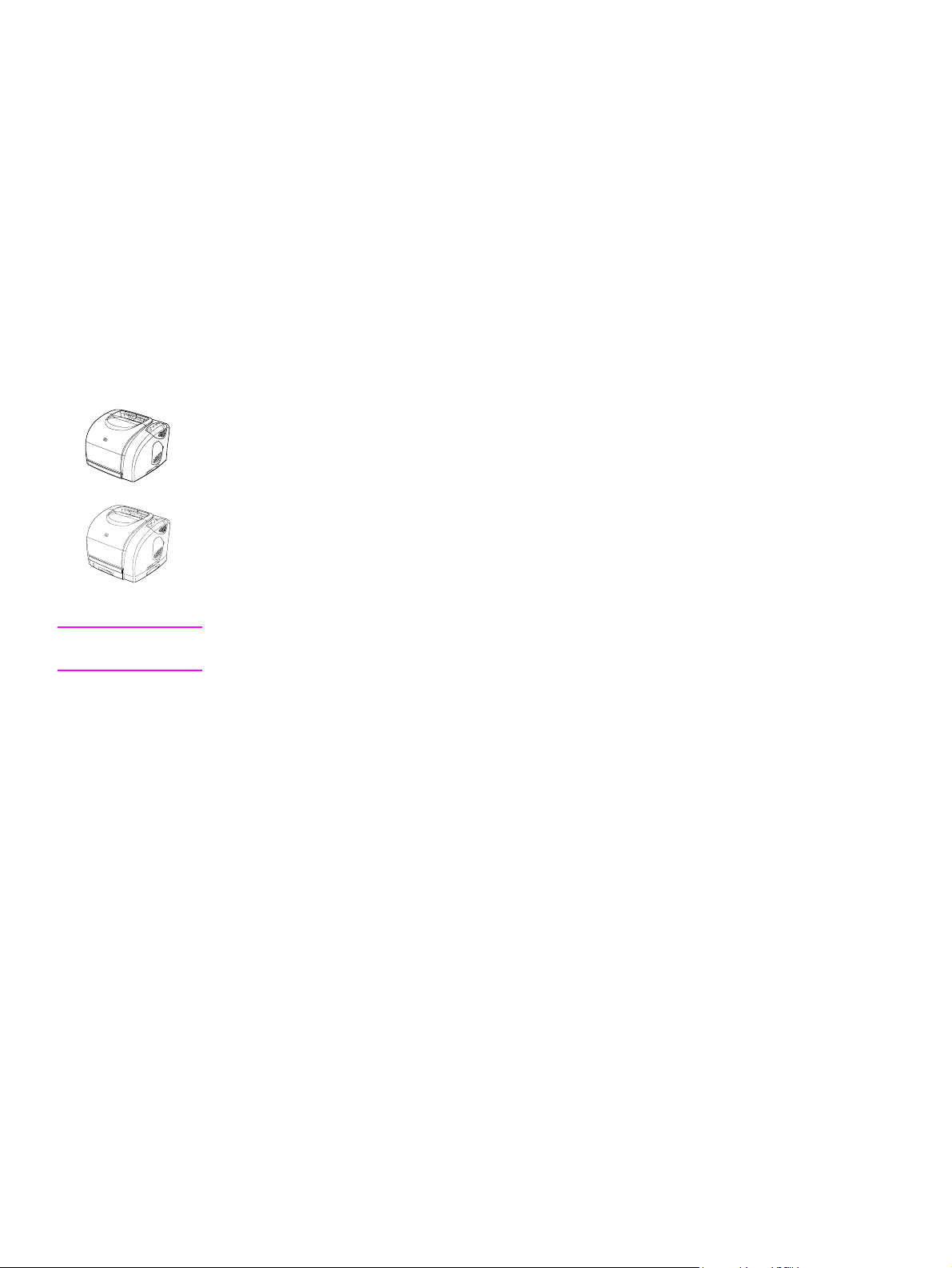
HP color LaserJet 1500 series printer features and
configurations
The HP color LaserJet 1500 series printer is a four-color laser printer that prints at 16 pages per
minute (ppm) in black, and 4 ppm in color.
● Trays—The printer comes with a multipurpose tray (tray 1) that holds up to 125 sheets of
various print media or 10 envelopes. The HP color LaserJet 1500L printer is compatible with
a 250-sheet tray (optional tray 2) for standard sizes of paper. HP color LaserJet 1500 printer
comes with both tray 1 and tray 2.
● Connectivity—The printer provides a HI-SPEED universal serial bus (USB) port for
connectivity.
● Memory—The printer contains 16 MB RAM, which cannot be expanded.
HP color LaserJet 1500L printer
The HP color LaserJet 1500L printer comes with tray 1 (multipurpose tray), and accepts th e
optional tray 2.
HP color LaserJet 1500 printer
The HP color LaserJet 1500 printer comes with tray 1 and tray 2.
Note Because tray 2 is not included with both models, it is referred to as optional tray 2 in this
documentation.
16 Product Information Q2488-90901
Page 17
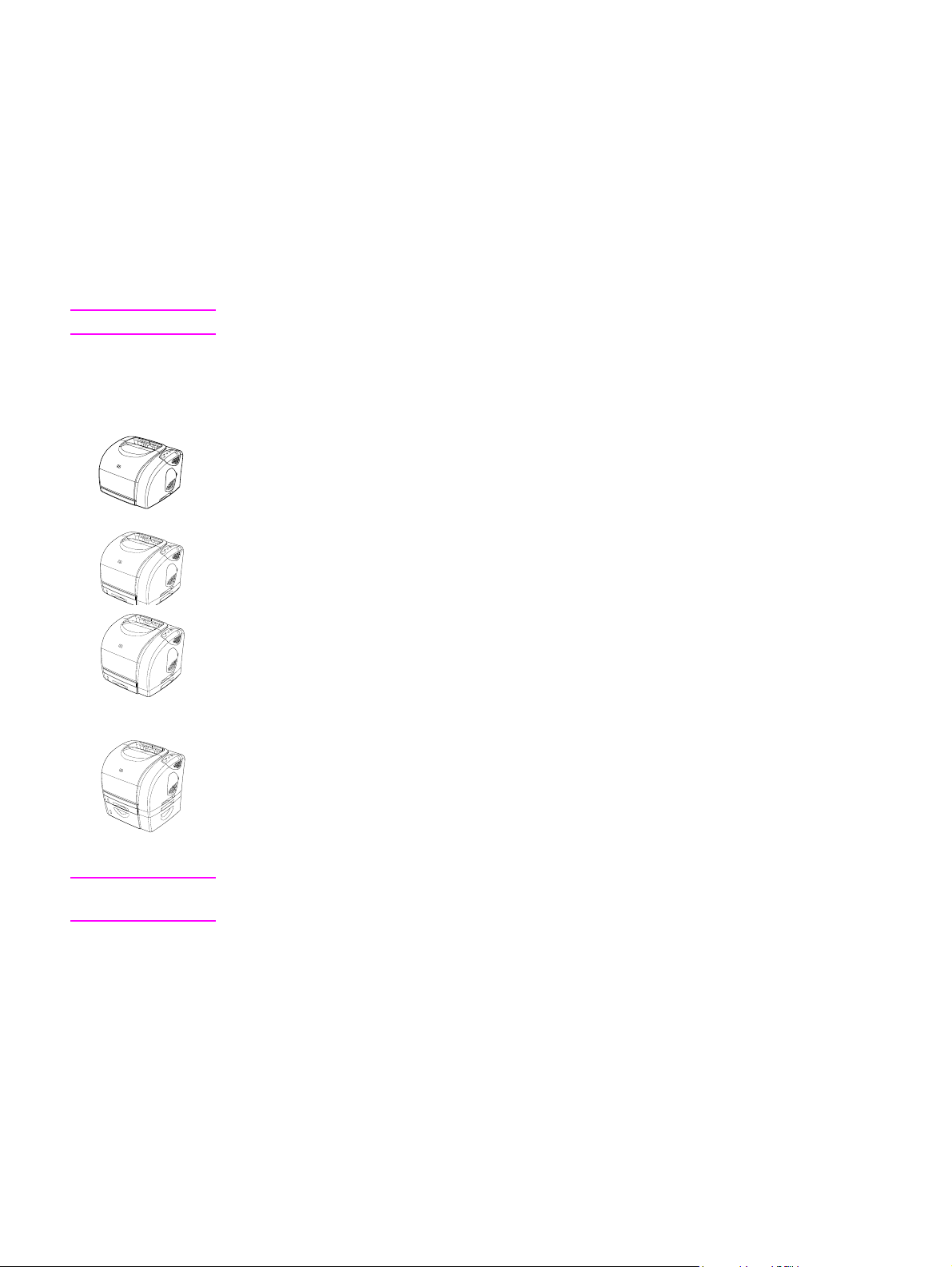
HP color LaserJet2500 series printer features and
configurations
The HP color LaserJet 2500 series printer is a four -color laser p rinter that p rints at 16 p age s per
minute (ppm) in black, and 4 ppm in color.
● Trays—The printer comes with a multipurpose tray (tray 1) that holds up to 125 sheets of
various print media or 10 envelopes. The HP color LaserJet 2500L is compatible with a 250sheet tray (optional tray 2) for standard sizes of paper and a 500-sheet tray (op tional tray 3)
for A4 and letter sizes. (Optional tray 2 must be installed in order to install optional tray 3.)
● Connectivity—The printer provides parallel and USB ports for connectivity. The printer also
contains an EIO slot for installing an optional HP Jetdirect print server.
Note The parallel and USB ports cannot be connected at the same time.
● Memory—The printer contains three DIMM slots. The standard 64-MB RAM DIMM resides
in one of the slots. The printer memory can be e x pande d to a t otal of 256 MB using 3 2-, 64- ,
or 128-MB RAM DIMMs. A language font DIMM can be installed in one of the DIMM slots.
HP color LaserJet 2500L printer
The HP color LaserJet 2500L printer comes with tray 1 (multipurpose tray), and accepts optional
trays 2 and 3.
HP color LaserJet 2500 printer
The HP color LaserJet 2500 printer comes with tray 1 and tray 2, and accepts optional tray 3.
HP color LaserJet 2500n printer
● The HP color LaserJet 2500n printer comes with tray 1 and tray 2, and accepts optional
tray 3.
● The printer comes with an HP Jetdirect 615n print server card for connecting to a
10/100Base-T network.
HP color LaserJet 2500tn printer
● The HP color LaserJet 2500tn printer comes with tray 1, tray 2, and tray3.
● The printer comes with an HP Jetdirect 615n print server card for connecting to a
10/100Base-T network.
Note Because tray 2 and tray 3 are not included with all models, they are referred to as optional tr a y 2
and optional tray 3 in this documentation.
ENWW 1 Product Information 17
Page 18

Product specifications
Table 1. Product features
Category HP color LaserJet 1500 series printer
feature
Color printing ● Prints in color using the four process colors:
cyan, magenta, yellow, and black.
Fast print speed
Excellent print quality
Ease of use
Expandability
● Prints letter-size paper at 16 ppm for black or
4 ppm for color.
● True 600-by-600 dpi text and graphics.
● ImageREt 2400 provides 2400-dpi color laser
print quality through a multilevel printing
process.
● Adjustable settings to optimize print quality.
● The HP UltraPrecise print cartridge has a finer
toner formulation that provides sharper text and
graphics.
● Few supplies to order. Supplies are easy to
install.
● Convenient access to printer information and
settings using software tools
(HP color LaserJet 1500 Series Toolbox).
● Optional tray 2 is included with the
HP color LaserJet 1500 printer and is
compatible with the
HP color LaserJet 1500L model. This 250-sheet
tray for standard paper sizes reduces the
frequency with which you have to add paper to
the printer. Only one 250-sheet tray can be
installed on the printer.
● Optional external HP Jetdirect print server for
connecting to a network.
HP color LaserJet 2500 series printer
feature
● Prints in color using the four process colors:
cyan, magenta, yellow, and black.
● Prints letter-size paper at 16 ppm for black or
4 ppm for color.
● True 600-by-600 dpi text and graphics.
● ImageREt 2400 provides 2400-dpi color laser
print quality through a multilevel printing
process.
● Adjustable settings to optimize print quality.
● The HP UltraPrecise print cartridge has a finer
toner formulation that provides sharper text and
graphics.
● Few suppl i es to order. Supplies are easy to
install.
● Convenient access to printer information and
settings using software tools
(HP color LaserJet 2500 Series Toolbox,
embedded Web server, Printer Status and
Alerts).
● Optional tray 2 is included with the 2500, 2500n,
and 2500tn models and is compatible with the
2500L model. This 250-sheet tray for standard
paper sizes reduces the frequency with which
you have to add paper to the printer. Only one
250-sheet tray can be installed on the printer.
● Optional tray 3 is inclu ded with the 2500tn
model and is compatible with the 2500L, 2500,
and 2500n models. This 500-sheet tray for
letter- and A4-size paper reduces the frequency
with which you have to add paper to the printer.
Only one 500-sheet tray can be installed on the
printer.
NOTE: Optional tra y2 must be installed in order
to install optional tray 3.
● Optional HP Jetdirect print server card for
connecting to a network. Included with the
2500n and 2500tn models; compatible with the
2500L and 2500 models.
● Two additional DIMM slots for adding memory
and fonts.
NOTE: The printer has three DIMM slots, but the
first slot (the slot on the left) might contain a
flash DIMM.
18 Product Information Q2488-90901
Page 19

Table 1. Product features (continued)
Category HP color LaserJet 1500 series printer
feature
Flexible paper
handling
Printer control
language (PCL)
printer language and
fonts
PostScript® (PS) 3
emulation language
and fonts
Automatic language
switching
Interface connections
Networking
● Adjustable tray 1 for letterhead, envelopes,
labels, transparencies, custom-sized media,
postcards, and heavy paper.
● Optional tray 2 for standard-size paper.
● One 125-sheet output bin (top output bin).
Select the top output bin (face-down bin) for
most jobs, including transparencies.
NOTE: HP color LaserJet 1500 series printers
do not print in color on transparencies.
● One rear output door. Use the rear output door
(face-up) for jobs on heavy paper, light paper, or
special print media, excluding transparencies.
● Straight-through paper path available from tr ay 1
to the rear output door.
● Manual duplexing. See the
HP Color LaserJet 1500 Series Printer User
Guide for more information.
● Hi-Speed USB port.
● Optional HP Jetdirect print server .
● All common network protocols such as Ethernet,
Token Ring, and LocalTalk are available using
optional external HP Jetdirect print server cards.
Compatible external HP Jetdirect print servers
are the HP Jetdirect 175x (model J6035A) and
the HP Jetdirect 310x (model J6038A).
● Wireless networking (802.11b) is available with
the HP Jetdirect 380x print server (model
J6061A).
HP color LaserJet 2500 series printer
feature
● Adjustable tray 1 for letterhead, envelopes,
labels, transparencies, custom-sized media,
postcards, and heavy paper.
● Optional tray 2 for standard-size paper.
● Optional tray 3 for letter- and A4-size paper.
● One 125-sheet output bin (top output bin).
Select the top output bin (face-down bin) for
most jobs, including transparencies.
NOTE: HP color LaserJet 2500 series printers
do not print in color on transparencies.
● One rear output door. Use the rear output door
(face-up) for jobs on heavy paper, light paper, or
special print media, excluding transparencies.
● Straight-through paper path available from tray 1
to the rear output door.
● Manual duplexing. See the
HP Color LaserJet 2500 Series Printer User
Guide for more information.
● Fast printing performance, built-in Intellifont and
TrueType™ scaling technologies, built-in HP-GL/
2 vector graph i cs, and advanced imaging
capabilities are benefits of the PCL 5 and PCL 6
printer languages. PCL 5 and PCL 6 also
include 45 scalable TrueType fonts and one
bitmapped line printer (LP) font. PCL 5 and
PCL 6 printer languages also included.
● PostScript (PS) 3 emulation with 35 built-in PS
language fonts included.
● The printer automatically determines and
switches to the appropriate printer language
(such as PS) for the print job.
● Bidirectional enhanced capabilities port (ECP)
type-B parallel port (IEEE-1284 compliant).
● USB port. A parallel cable and a USB cable
cannot be connected at the same time. If they
are, then USB is disabled.
● EIO slot in the 2500L and 2500 models. The
2500n and 2500tn models include the optional
HP Jetdirect 615n print server card.
● The 2500L and 2500 models provide an EIO slot
for an optional HP Jetdirect print server card for
fast and easy connectivity. (The 2500n and
2500tn models include the HP Jetdirect 61 5n
print server card.)
● All common network protocols such as Ethernet,
Token Ring, and LocalTalk are available using
HP Jetdirect print server cards.
● Wireless networking (802.11b) is available with
the HP Jetdirect 615n print server card (model
J6058A).
ENWW 1 Product Information 19
Page 20

Table 1. Product features (continued)
Category HP color LaserJet 1500 series printer
feature
Enhanced memory ● The printer comes with 16 MB of memory that
cannot be expanded.
Energy savings
Economical printing
Print cartridges
● The printer automatically conserves electricity
by substantially reducing power consumption
when you are not printing.
● As an ENERGY STAR
®
partner, Hewlett-Packard
Company has determined that this product
meets E
NERGY STAR guidelines for energy
efficiency. ENERGY STAR® is a U.S. registered
service mark of the United States Environmental
Protection Agency.
● Pages-per-sheet printing and two-sided printing
using manual duplexing saves paper. See the
HP Color LaserJet 1500 Series Printer User
Guide for more information.
● The Supplies Status page includes print
cartridge and imag ing drum gauges that show
life remaining (for HP supplies only).
● No-shake cartridge design.
● Authentication f or HP print cartridges.
● Enabled supplies-ordering capability.
HP color LaserJet 2500 series printer
feature
● The printer comes with 64 MB of memory and
can be expanded to 256 MB by using the DIMM
slots.
● The printer automatically conserves electri city
by substantially reducing power consumption
when you are not printing.
● As an ENERGY STAR
Company has determined that this product
meets E
NERGY STAR guidelines for energy
efficiency. ENERGY STAR® is a U.S. registered
service mark of the United States Environmental
Protection Agency.
● Pages-per-sheet printing and two-sided printing
using manual duplexing saves paper. See the
HP Color LaserJet 2500 Series Printer User
Guide for more information.
● The Supplies Status page includes print
cartridge and imaging drum gauges that show
life remaining (for HP supplies only).
● No-shake cartridge design.
● Authentication for HP print cartridges.
● Enabled supplies-ordering capability.
®
partner, Hew le tt-Packa r d
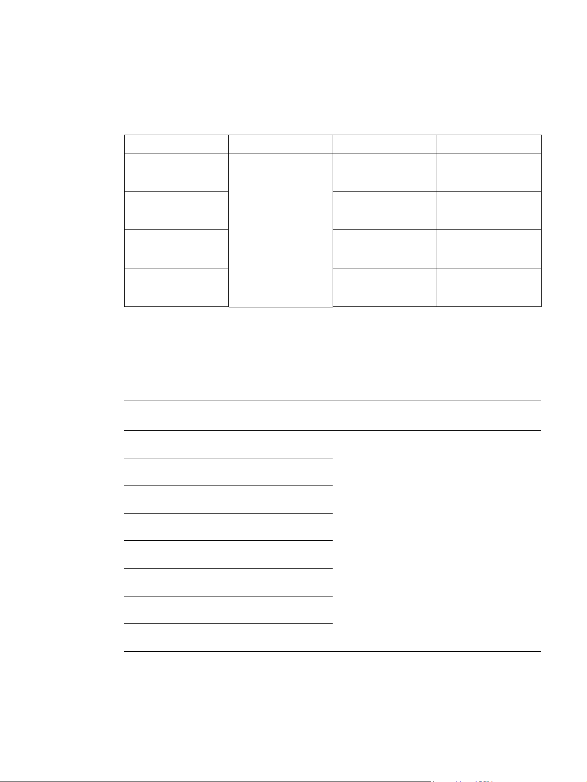
Table 2. Physical specifications
HP color LaserJet1500
Category HP color LaserJet 1500L
Height 325 mm (12.80 inches) 376 mm (14.80 inches)
Width 482 mm (18.98 inches) 482 mm (18.98 inches)
Depth (body) 451 mm (17.76 inches) 451 mm (17.76 inches)
Weight (with
21.5 kg (47.5 lbs) 23.9 kg (52.7 lbs)
supplies)
HP LaserJet 2500 without
Category
Height 325 mm (12.80 inches) 376 mm (14.81 inches) 512 mm (20.16 inches)
Width 482 mm (18.98 inches) 482 mm (18.98 inches) 482 mm (18.98 inches)
Depth (body) 452 mm (17.80 inches) 452 mm (17.80 inches) 452 mm (17.80 inches)
Weight (with
supplies)
optional trays 2 and 3
21.52 kg (47.45 lbs) 23.9 kg (52.7 lbs) 29.27 kg (64.55 lbs)
with optional tray 2 (250-sheet)
HP LaserJet 2500 with
optional tray 2 (250-sheet)
HP LaserJet 2500 with
optional tray 3 (500-sheet)
20 Product Information Q2488-90901
Page 21

Table 3. Consumables specifications
Category Specification
Imaging-drum life 20,000 pages when printing only in black
5,000 pages when printing in color
6,000 to 8,000 pages is the average life
Print-cartridge life Black: 5,000 pages
Yellow, cyan, and magenta: 4,000 pages each
Table 4. Electrical specifications
Category 110-volt models 220-volt models
Power requirements 115 to 127 V (+/- 10%)
60 Hz (+/- 2 Hz)
Minimum
recommended circuit
capacity for typical
product
Average power
consumption (watts)
12 Amps 6 Amps
Printing, color = 400 W
Printing, monochrome = 224 W
Standby = 30 W
Off = 0 W
220 to 240 V (+/- 10%)
50 Hz (+/- 2 Hz)
Printing, color = 403 W
Printing, monochrome = 217 W
Standby = 31 W
Off = 0 W
CAUTION Po wer re quirements ar e based on the region where the printer is sold. Do not con vert operating
voltages. This will damage the printer and void the product warranty.
Table 5. Environmental specifications
Category Operating Storage
Temperature
(printer and print
cartridge)
Relative humidity 10 to 80 percent 95 percent or less
15° to 32.5° C
° to 90.5° F)
(59
-20
° to 40° C
(-4° to 104° F)
Table 6. Acoustic emissions (declared per ISO 9296)
Category Printing (16 ppm) Standby
Sound power L
Sound pressure:
Operation position
Sound pressure:
Bystander position
= 6.7 bels(A) (not audible)
WAd
= 62 dB(A) (not audible)
L
pAm
L
= 52 dB(A) (not audible)
pAm
Note Acoustic emissions values are subje ct to change. See http://www.hp.com/support/clj1500 or http:/
/www.hp.c om/support/clj2500 for current information.
ENWW 1 Product Information 21
Page 22
Media specifications
This section contains information about the sizes, weights, and capacities of media that each tray
supports.
Table 7. Tray 1 specifications
Tr ay 1 Di mensions
1
Weight or thickness Capacity
2
Paper Minimum:
76 by 127 mm
(3 by 5 inches)
Transparencies and
opaque film
3
Labels
Maximum:
216 by 356 mm
(8.5 by 14 inches)
Weight:
60 to 177 g/m
2
(16 to 47 lb)
Thickness:
0.10 to 0.13 mm
(0.0039 to 0.0051 inches)
Thickness:
125 sheets of 75-g/m
(20-lb) paper
50 typically
50 typically
up to 0.23 mm
(up to 0.0091 inches)
Envelopes Weight:
up to 10
Up to 90 g/m2
(16 to 24 lb)
1. The printer supports a wide range of standard and custom sizes of print media. Check the printer driver for
supported sizes.
2. Capacity can vary depending on media weight and thickness, and environmental conditions.
3. Smoothness: 100 to 250 (Sheffield).
Table 8. Optional tray 2 specifications
Optional tray 2
(250-sheet tray)
Letter 216 by 279 mm
A4 210 by 297 mm
A5 148 by 210 mm
1
Dimensions
(8.5 by 11 inches)
2
Weight Capacity
60 to 105 g/m2
(16 to 28 lb)
250 sheets of 75-g/m2
(20-lb) paper
3
(8.3 by 11.7 inches)
(5.8 by 8.3 inches)
2
B5 (ISO) 176 by 250 mm
(6.9 by 9.9 inches)
B5 (JIS) 182 by 257 mm
(7.2 by 10 inches)
Executive 191 by 267 mm
(7.3 by 10.5 inches)
Legal 216 by 356 mm
(8.5 by 14 inches)
8.5 by 13 inch 216 by 330 mm
(8.5 by 13 inches)
1. Optional tray 2 supports paper only.
2. The printer supports a wide range of standard and custom sizes of print media. Check the printer driver for
supported sizes.
3. Capacity can vary depending on media weight and thickness, and environmental conditions.
22 Product Information Q2488-90901
Page 23

Table 9. Optional tray 3 specifications (HP LaserJet 2500 series printers only)
Optional tray 3
1
(500-sheet tray)
Letter 216 by 279 mm
A4 210 by 297 mm
1. Optional tray 3 supports paper only.
2. The printer supports a wide range of standard and custom sizes of print media. Check the printer driver for
supported sizes.
3. Capacity can vary depending on media weight and thickness, and environmental conditions.
Model and serial numbers
The model number and serial number are listed on an identificat ion label located un derneath the
top door.
The serial number contains information abo ut the co un try of origin and the revision level,
manufacturing date , production code, and production number of the product.
The label also contains power rating and regulatory information.
Dimensions
(8.5 by 11 inches)
(8.3 by 11.7 inches)
2
Weight Capacity
60 to 105 g/m
(16 to 28 lb)
2
500 sheets of 75-g/m2
(20-lb) paper
3
HP color LaserJet 1500 series printer identification label
HP color LaserJet 2500 series printer identification label
ENWW 1 Product Information 23
Page 24
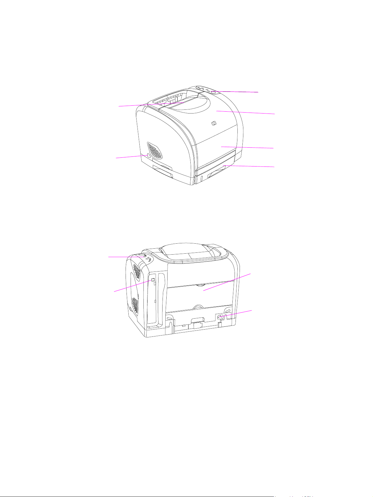
Printer overview
HP color LaserJet 1500 series printer
Front and left-side view
T op outpu t
Control panel
bin
Top cover
Power
switch
Figure 1. Front and left-side view—HP color LaserJet 1500 series printers
Back and right-side view
Control
panel
Rear output door
Hi-Speed
USB port
Power connector
Tray 1
Optional tray 2
Figure 2. Back and right-side view—HP color LaserJet 1500 series printers
24 Product Information Q2488-90901
Page 25
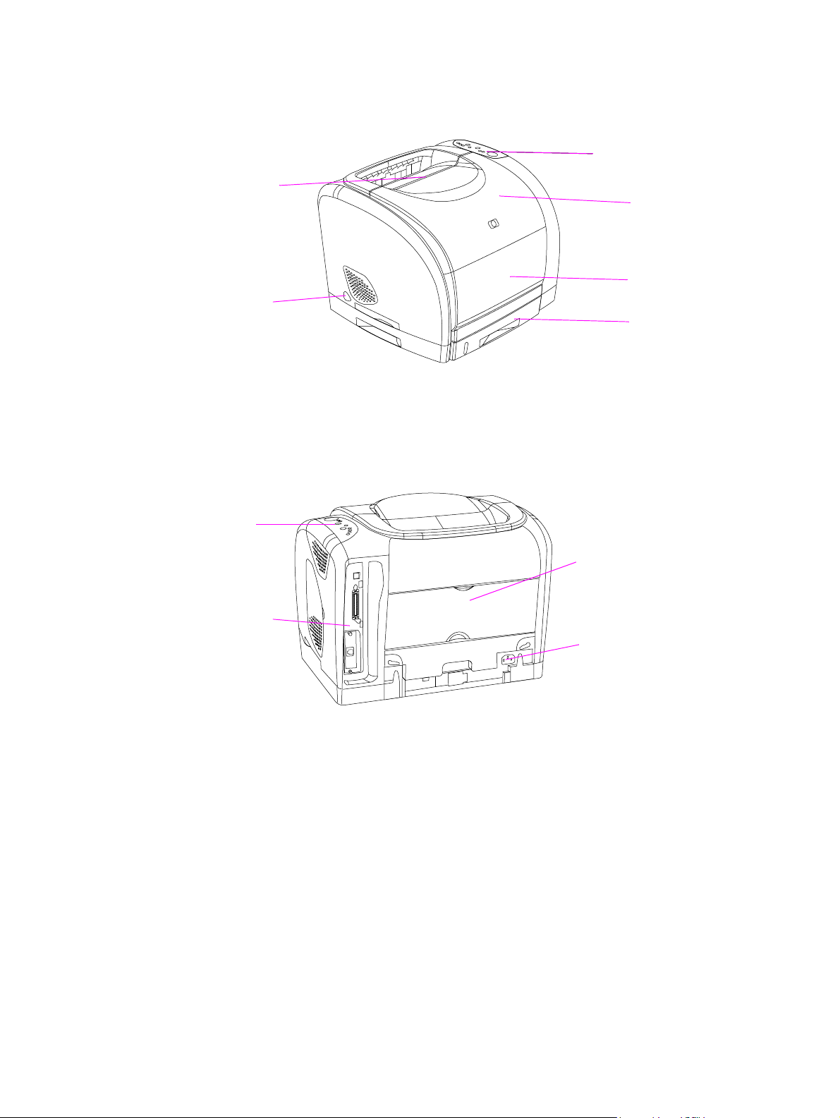
HP color LaserJet 2500 series printer
Front and left-side view
T op outpu t
bin
Control panel
Top cover
Power
switch
Figure 3. Front and left-side view—HP color LaserJet 2500 series printers
Back and right-side view
Control
panel
Rear output door
Interface
ports (see
page 36)
Power connector
Tray 1
Optional tray 2
(2500, 2500n, and
2500tn)
Figure 4. Back and right-side view—HP color LaserJet 2500 series printers
ENWW 1 Product Information 25
Page 26

Warranty statements
HP color LaserJet 1500 series printer
Hewlett-Packard limited warranty statement
HP PRODUCT DURATION OF WARRANTY
HP color LaserJet 1500L, 1500 1 year, Return to Authorized Service Center
1. HP warrants to you, the end-user customer, that HP hardware and accessories will be free from defects in
materials and workmanship after the date of purchase, for the period specified above. If HP receives notice of
such defects during the warranty period, HP will, at its option, either repair or replace products which pro ve to be
defective. Replacement products may be either new or equivalent in performance to new.
2. HP warrants to you that HP software will not fail to execute its programming instructions after the date of
purchase, for the period specified abo ve , due to def ects in material and workmanship when prop erly installed and
used. If HP receives notice of such defects during the warranty period, HP will replace software which does not
exe cute its programming instructions due to such def ects.
3. HP does not warrant that the operation of HP products will be uninterrupted or error free. If HP is unable, within a
reasonable time, to repair or replace any product to a condition as warranted, you will be entitled to a refund of
the purchase price upon prompt return of the product.
4. HP products may contain remanufactured parts equivalent to new in performance or may have been subject to
incidental use.
5. Warranty does not apply to defects resulting from (a) improper or inadequate maintenance or calibration, (b)
software, interfacing, parts or supplies not supplied by HP, (c) unauthorized modification or misuse, (d ) operation
outside of the published environmental specifications for the product, or (e) improper site preparation or
maintenance.
6. TO THE EXTENT ALLOWED BY LOCAL LAW, THE ABOVE WARRANTIES ARE EXCLUSIVE AND NO OTHER
WARRANTY OR CONDITION, WHETHER WRITTEN OR ORAL, IS EXPRESSED OR IMPLIED AND HP
SPECIFICALLY DISCLAIMS ANY IMPLIED WARRANTIES OR CONDITIONS OF MERCHANTABILITY,
SATISFA CTORY QUALITY, AND FITNESS FOR A PARTICULAR PURPOSE. Some countries/regions, states or
provinces do not allow limitations on the duration of an implied warranty, so the above limitation or exclusion
might not apply to you. This w arranty giv es yo u specific legal rights and y ou migh t also ha v e other rights that va ry
from country/region to country/region, state to state , or province to province .
7. HP’s limited warranty is valid in any country/region or locality where HP has a support presence for this product
and where HP has marketed this product. The level of warranty service you receive may vary according to local
standards. HP will not alter form, fit or function of the product to make it operate in a country/region for which it
was never intended to function for legal or regulatory reasons.
8. TO THE EXTENT ALLOWED BY LOCAL LA W, THE REMEDIES IN THIS WARRANTY STA TEMENT ARE YOUR
SOLE AND EXCLUSIVE REMEDIES. EXCEPT AS INDICATED ABOVE, IN NO EVENT WILL HP OR ITS
SUPPLIERS BE LIABLE FOR LOSS OF DATA OR FOR DIRECT, SPECIAL, INCIDENTAL, CONSEQUENTIAL
(INCLUDING LOST PROFIT OR DATA), OR OTHER DAMAGE, WHETHER BASED IN CONTRACT, TORT, OR
OTHER WISE. Some countries/regions , states or province s do not allo w the e xclusion or limitation of incidental or
consequential damages, so the above limitation or exclusion may not apply to you.
THE WARRANTY TERMS CONTAINED IN THIS STATEMENT, EXCEPT TO THE EXTENT LAWFULLY
PERMITTED, DO NOT EXCLUDE, RESTRICT OR MODIFY AND ARE IN ADDITION TO THE MANDATORY
STATUTORY RIGHTS APPLICABLE TO THE SALE OF THIS PRODUCT TO YOU.
26 Product Information Q2488-90901
Page 27

HP color LaserJet 2500 series printer
Hewlett-Packard limited warranty statement
HP PRODUCT DURATION OF WARRANTY
HP color LaserJet 2500L, 2500, 2500n, 2500tn 1 year, Return to Authorized Service Center
1. HP warrants to you, the end-user customer, that HP hardware and accessories will be free from defects in
materials and workmanship after the date of purchase, for the period specified above. If HP receives notice of
such defects during the warranty period, HP will, at its option, either repair or replace products which prove to be
defective. Replacement products may be either new or equivalent in performance to new.
2. HP warrants to you that HP software will not fail to execute its progra mming instructions after the date of
purchase, fo r the period specified abo ve , due to def ects in material and w orkmanship when properly installed an d
used. If HP receives notice of such defects during the warranty period, HP will replace software which does not
execute its programming instructions due to such defects.
3. HP does not warrant that the operation of HP products will be uninterrupted or error free. If HP is unable, within a
reasonable time, to repair or replace any product to a condition as warranted, you will be entitled to a refund of
the purchase price upon prompt return of the product.
4. HP products may contain remanufactured parts equivalent to new in performance or may hav e been subject to
incidental use.
5. Warranty does not apply to defects resulting from (a) improper or inadequate maintenance or calibration, (b)
software, interfacing, parts or supplies not supplied by HP, (c) unauthorized modification or misuse, (d) operatio n
outside of the published environmental specifications for the product, or (e) imprope r s ite pre pa ration or
maintenance.
6. TO THE EXTENT ALLOWED BY LOCAL LAW, THE ABOVE WARRANTIES ARE EXCLUSIVE AND NO OTHER
WARRANTY OR CONDITION, WHETHER WRITTEN OR ORAL, IS EXPRESSED OR IMPLIED AND HP
SPECIFICALLY DISCLAIMS ANY IMPLIED WARRANTIES OR CONDITIONS OF MERCHANTABILITY,
SATISFACTORY QUALITY, AND FITNESS FOR A PARTICULAR PURPOSE. Some countries/regions, states or
provinces do not allow limitations on the duration of an implied warranty, so the above limitation or exclusion
might not apply to you. This w arr anty giv es y ou specif ic legal rights and y ou mig ht also ha v e ot her rights that v ary
from country/region to country/region, state to state, or province to province.
7. HP’s limited warranty is valid in any country/region or locality where HP h as a support presence for this product
and where HP has marketed this product. The level of warranty service you receive may vary according to local
standards. HP will not alter form, fit or function of the product to make it operate in a country/region for which it
was never intended to function for legal or regulatory reasons.
8. TO THE EXTENT ALLO WED BY LOCAL LAW, THE REMEDIES IN THIS WARRANTY STA TEMENT ARE YOUR
SOLE AND EXCLUSIVE REMEDIES. EXCEPT AS INDICATED ABOVE, IN NO EVENT WILL HP OR ITS
SUPPLIERS BE LIABLE FOR LOSS OF DATA OR FOR DIRECT, SPECIAL, INCIDENTAL, CONSEQUENTIAL
(INCLUDING LOST PROFIT OR DATA), OR OTHER DAMAGE, WHETHER BASED IN CONTRACT, TORT, OR
OTHERWISE. Some countries/regions, states or provinces do not allow the exclusion or limitation of incidental or
consequential damages, so the above limitation or exclusion may not apply to you.
THE WARRANTY TERMS CONTAINED IN THIS STATEMENT, EXCEPT TO THE EXTENT LAWFULLY
PERMITTED, DO NOT EXCLUDE, RESTRICT OR MODIFY AND ARE IN ADDITION TO THE MANDATORY
STATUTORY RIGHTS APPLICABLE TO THE SALE OF THIS PRODUCT TO YOU.
ENWW 1 Product Information 27
Page 28

Limited warranty for the print cartridges and imaging drum
This HP product is warranted to be free from defects in materials and workmanship during its
useful life (end of life is indicated by a printer control panel low-life message).
This warranty does not cover products that have been modified, refurbished, remanufactured,
misused or tampered with in any way.
This limited warranty gives you specific legal rights. You may have other rights which vary from
state to state, province to province and country/region to country/region.
THE ABOVE WARRANTIES ARE E XCLUSIVE AND NO OTHER WARRANTY, WHETHER
WRITTEN OR ORAL, IS EXPRESSED OR IMPLIED. THE HEWLETT-PACKARD COMPANY
SPECIFICALLY DISCLAIMS THE IMPLIED WARRANTIES OR MERCHANTABILITY AND
FITNESS FOR A PARTICULAR PURPOSE. TO THE EXTENT ALLOWED BY APPLICABLE
LAW, IN NO EVENT SHALL HEWLETT-PACKARD COMPANY BE LIABLE FOR ANY
INCIDENTAL, CONSEQUENTIAL, SPECIAL, INDIRECT, PUNITIVE, OR EXEMPLARY
DAMAGES OR LOST PROFITS FROM ANY BREACH OF THIS WARRANTY OR
OTHERWISE.
In the event that your product proves to be defective, please return to place of purchase with a
written description of the problem.
28 Product Information Q2488-90901
Page 29

Regulatory statements
HP color LaserJet 1500 series printer
declaration of conformity
according to ISO/IEC Guide 22 and EN 45014
Manufacturer's Name: Hewlett-Packard Company
Manufacturer's Address: 11311 Chinden Boulevard
declares, that the product
Product Name: HP color LaserJet 1500L, 1500
Model Number: BOISB-0209-00
Product Options: ALL
conforms to the following Product Specifications:
Boise, Idaho 83714-1021, USA
Including: 250-sheet paper feeder unit
Safety: IEC 60950:1991+A1+A2+A3+A4 / EN 60950:1992+A1+A2+A3+A4+A11
IEC 60825-1:1993+A1 / EN 60825-1:1994+A11 (Class 1 Laser/LED Product)
GB4943-1995
EMC: CISPR 22:1993+A1+A2 / EN 55022:1994+A1+A2 Class B
EN 61000-3-2:1995 / A14
EN 61000-3-3:1995
EN 55024:1998
FCC Title 47 CFR, Part 15 Class B
AS / NZS 3548:1995+A1+A2
2
/ ICES-003, Issue 3/ GB9254-1998
1*
Supplementary Information:
The product herewith complies with the requirements of the EMC Directive 89/336/EEC and the Low
Voltage Directive 73/23/EEC, and carries the CE-marking accordingly.
1) The product was tested in a typical configuration with Hewlett-Packard Personal Computer
Systems.
2) This Device complies with Part 15 of the FCC Rules. Operation is subject to the following two
conditions: (1) this device may not cause harmful interference, and (2) this device must accept any
interference received, including interference that may cause undesired operation.
Boise, Idaho USA
1 January, 2002
For regulatory topics only:
Australia Contact: Product Regulations Manager, Hewlett-Packard Australia Ltd., 31-41 Joseph
European Contact: Your Local Hewlett-Packard Sales and Service Office or Hewlett-Packard
USA Contact: Product Regulations Manager, Hewlett-Packard Company, PO Box 15, Mail
Street, Blackburn, Victoria 3130, Australia
GmbH, Department HQ-TRE / Standards Europe, Herrenberger Straße 130,
D-71034 Böblingen (FAX: +49-7031-14-3143)
Stop 160, Boise, ID 83707-0015 (Phone: 208-396-6000)
ENWW 1 Product Information 29
Page 30

HP color LaserJet 2500 series printer
declaration of conformity
according to ISO/IEC Guide 22 and EN 45014
Manufacturer's Name: Hewlett-Packard Company
Manufacturer's Address: 11311 Chinden Boulevard
Boise, Idaho 83714-1021, USA
declares, that the product
Product Name: HP color LaserJet 2500L, 2500, 2500n, 2500tn
Including: 250-sheet and 500-sheet paper feeder unit
Model Number: C9705A, C9706A, C9707A, C9708A
Including: C9698A, C9699A
Product Options: ALL
conforms to the following Product Specifications:
Safety: IEC 60950:1991+A1+A2+A3+A4 / EN 60950:1992+A1+A2+A3+A4+A11
IEC 60825-1:1993+A1 / EN 60825-1:1994+A11 (Class 1 Laser/LED Product)
GB4943-1995
EMC: CISPR 22:1993+A1+A2 / EN 55022:1994+A1+A2 Class B
EN 61000-3-2:1995 / A14
EN 61000-3-3:1995
EN 55024:1998
FCC Title 47 CFR, Part 15 Class B
AS / NZS 3548:1995+A1+A2
2
/ ICES-003, Issue 3/ GB9254-1998
1*
Supplementary Information:
The product herewith complies with the requirements of the EMC Directive 89/336/EEC and the Low
Voltage Directive 73/23/EEC, and carries the CE-marking accordingly.
1) The product was tested in a typical configuration with Hewlett-Packard Personal Computer
Systems.
2) This Device complies with Part 15 of the FCC Rules. Operation is subject to the following two
conditions: (1) this device may not cause harmful interference , and (2) this device m ust accept any
interference received, including interference that may cause undesired operation.
* This product includes LAN (Local Area Network) options. When the interface cable is attached
to LAN connectors, the product meets the requirements of EN55022 Class A in which case the
following applies: “Warning — This is a class A product. In a domestic en vironment this product
may cause radio interference in which case the user may be required to take adequate
measures.”
3) The model number may include an additional suffix letter “R”.
Boise, Idaho USA
6 June, 2002
For regulatory topics only:
Australia Contact: Product Regulations Manager, Hewlett-Packard Australia Ltd., 31-41 Joseph
European Contact: Your Local Hewlett-Packard Sales and Service Office or Hewlett-Packard
USA Contact: Product Regulations Manager, Hewlett-Packard Company, PO Box 15, Mail
Street, Blackburn, Victoria 3130, Australia
GmbH, Department HQ-TRE / Standards Europe, Herrenberger Straße 130,
D-71034 Böblingen (FAX: +49-7031-14-3143)
Stop 160, Boise, ID 83707-0015 (Phone: 208-396-6000)
30 Product Information Q2488-90901
Page 31

Laser safety statement
The Center for Devices and Radiological Health (CDRH) of the U.S. Food and Drug
Administration has implemented regulations for laser products manufactured since August 1,
1976. Compliance is mandatory for products marketed in the United States. The printer is
certified as a “Class 1” laser product under the U.S. Department of Health and Human Services
(DHHS) Radiation Performance Standard according to the Radiation Control for Health and
Safety Act of 1968.
Because radiation that is emitted inside the printer is completely confined within protective
housings and external covers, the laser beam cannot escape during any phase of normal user
operation.
WARNING! Using controls, making adjustments , or performing procedures other than those specified in this
user guide can result in exposure to hazardous radiation.
Canadian DOC statement
Complies with Canadian EMC Class B requirements.
«Conforme à la classe B des normes canadiennes de compatibilité électromagnétiques (CEM).»
VCCI statement (Japan)
Korean EMI statement
ENWW 1 Product Information 31
Page 32

Finnish laser statement
LASERTURVALLISUUS
LUOKAN 1 LASERLAITE
KLASS 1 LASER APPARAT
HP color LaserJet 1500 -laserkirjoitin on käyttäjän kannalta turvallinen luokan 1 laserlaite.
Normaalissa käytössä kirjoittimen suojakotelointi estää lasersäteen pääsyn laitteen ulkopuolelle.
Laitteen turvallisuusluokka on määritetty standardin EN 60825-1 (1993) mukaisesti.
VAROITUS!
Laitteen käyttäminen muulla kuin käyttöohjeessa mainitulla tavalla saattaa altistaa käyttäjän
turvallisuusluokan 1 ylittävälle näkymättömälle lasersäteilylle.
VARNING!
Om apparaten används på annat sätt än i b ruksanvisning specificer ats , kan an vändaren utsätt as
för osynlig laserstrålning, som överskrider gränsen för laserklass 1.
HUOLTO
HP color LaserJet 1500 -kirjoittimen sisällä ei ole käyttäjän huollettavissa olevia kohteita.
Laitteen saa avata ja huoltaa ainoastaan sen huoltamiseen koulutettu henkilö. Tällaiseksi
huoltotoimenpiteeksi ei katsota väriainekasetin vaihtamista, paperiradan puhdistusta tai muita
käyttäjän käsikirjassa lueteltuja, käyttäjän tehtäväksi tarkoitettuja ylläpitotoimia, jotka voidaan
suorittaa ilman erikoistyökaluja.
VARO!
Mikäli kirjoittimen suojakotelo a v ataan, olet alttiina näkymät tömälle lasersäteilylle laitte en ollessa
toiminnassa. Älä katso säteeseen.
VARNING!
Om laserprinterns skyddshölje öppnas då apparaten är i funktion, utsättas användaren för
osynlig laserstrålning. Betrakta ej strålen.
Tiedot laitteessa käytettävän laserdiodin säteilyominaisuuksista:
Aallonpituus 770-795 nm
Teho 5 mW
Luokan 3B laser
32 Product Information Q2488-90901
Page 33

2 Installation and operation
Chapter contents
Operating environment . . . . . . . . . . . . . . . . . . . . . . . . . . . . . . . . . . . . . . . . . . 34
Interface ports . . . . . . . . . . . . . . . . . . . . . . . . . . . . . . . . . . . . . . . . . . . . . . . . . 35
HP color LaserJet 1500 series printer . . . . . . . . . . . . . . . . . . . . . . . . . . . 35
HP color LaserJet 2500 series printer . . . . . . . . . . . . . . . . . . . . . . . . . . . 36
Control panel features. . . . . . . . . . . . . . . . . . . . . . . . . . . . . . . . . . . . . . . . . . . 37
Understanding supplies status . . . . . . . . . . . . . . . . . . . . . . . . . . . . . . . . . 38
Understanding printer status . . . . . . . . . . . . . . . . . . . . . . . . . . . . . . . . . . 39
Selecting media. . . . . . . . . . . . . . . . . . . . . . . . . . . . . . . . . . . . . . . . . . . . . . . . 40
Input trays. . . . . . . . . . . . . . . . . . . . . . . . . . . . . . . . . . . . . . . . . . . . . . . . . 40
Supported print media . . . . . . . . . . . . . . . . . . . . . . . . . . . . . . . . . . . . . . . 42
Printer output paths. . . . . . . . . . . . . . . . . . . . . . . . . . . . . . . . . . . . . . . . . . . . . 43
Top output bin. . . . . . . . . . . . . . . . . . . . . . . . . . . . . . . . . . . . . . . . . . . . . . 43
Rear output door. . . . . . . . . . . . . . . . . . . . . . . . . . . . . . . . . . . . . . . . . . . . 43
Loading media. . . . . . . . . . . . . . . . . . . . . . . . . . . . . . . . . . . . . . . . . . . . . . . . . 44
Loading tray 1. . . . . . . . . . . . . . . . . . . . . . . . . . . . . . . . . . . . . . . . . . . . . . 44
Loading optional tray 2 . . . . . . . . . . . . . . . . . . . . . . . . . . . . . . . . . . . . . . . 45
Loading optional tray 3 . . . . . . . . . . . . . . . . . . . . . . . . . . . . . . . . . . . . . . . 46
Using the embedded Web server . . . . . . . . . . . . . . . . . . . . . . . . . . . . . . . . . . 47
Information tab . . . . . . . . . . . . . . . . . . . . . . . . . . . . . . . . . . . . . . . . . . . . . 48
Settings tab. . . . . . . . . . . . . . . . . . . . . . . . . . . . . . . . . . . . . . . . . . . . . . . . 48
Networking tab . . . . . . . . . . . . . . . . . . . . . . . . . . . . . . . . . . . . . . . . . . . . . 48
Other links. . . . . . . . . . . . . . . . . . . . . . . . . . . . . . . . . . . . . . . . . . . . . . . . . 49
Using Printer Status and Alerts. . . . . . . . . . . . . . . . . . . . . . . . . . . . . . . . . . . . 50
HP color LaserJet 1500 series printers . . . . . . . . . . . . . . . . . . . . . . . . . . 50
HP color LaserJet 2500 series printers . . . . . . . . . . . . . . . . . . . . . . . . . . 51
2 Installation and operation 33
Page 34

Operating environment
Place the printer on a sturdy, level surface in a well-ventilated area that meets the following
environmental requirements:
● temperature: 15° to 32.5° C (59° to 90.5° F)
● humidity: 10 percent to 80 percent relative humidity (no condensation)
● away from direct sunlight, open flames, and ammonia fumes
● with sufficient space around the printer for access and ventilation
1068 mm (42.0 inches)
387 mm
(15.2 inches)
505 mm (19.9 inches)
590 mm (23.2 inches)
830 mm (32.7 inches)
694 mm (27.3 inches)
643 mm (25.3 inches)
Figure 5. Space required
Note Only the HP color LaserJet 2500 series printer is equipped with the optional tr a y 3 that is shown
in figure 5.
34 Installation and operation Q2488-90901
Page 35

Interface ports
HP color LaserJet 1500 series printer
All HP color LaserJet 1500 series printers have a Hi-Speed USB port.
External HP Jetdirect print servers are not included with HP color LaserJet 1500 series printers.
Hi-Speed
USB port
Figure 6. HP color LaserJet 1500 series printer interface port
ENWW 2 Installation and operation 35
Page 36

HP color LaserJet 2500 series printer
HP color LaserJet 2500 series printers have two interface ports: an IEEE-1284B parallel port
and a USB port. The 2500L and 2500 models also contain an EIO slot for installing an optional
HP Jetdirect print server card. To order a print server card, see chapter 7, or contact your local
HP dealer.
The 2500n and 2500tn models include an H P Jetdirect 615n print server card that contains a
10/100Base-T (RJ-45) port.
Because the HP Jetdirect print server card is not included with all models, it will be ref erred to as
the optional HP Jetdirect print server card in this documentation.
Note You cannot connect the printer to one computer with a parallel cable and to another computer
with a USB cable. If you connect both types of cables, the USB is disabled. However, you can
connect one of the cables while the printer is connected to the network with an installed
HP Jetdirect print server card.
USB port
Parallel port
(IEEE-1284B)
Figure 7. HP color LaserJet 2500 series printer interface ports
(on the optional HP Jetdirect
615n print server card)
10/100Base-T
36 Installation and operation Q2488-90901
Page 37

Control panel features
The lights and buttons on the control panel are arranged into two main groups: supplies status
(top group) and printer status (bottom group). To interpret and troubleshoot control panel light
messages, see chapter 6.
The printer control panel contains the following lights and buttons:
Black print cartridge
light
Cyan print cartridge
light
Magenta print cartridge
light
Yellow print cartridge
light
R
OTATE CAROUSEL
button
Imaging drum
light
CANCEL JOB
button
Attention light
(amber)
Ready light
(green)
Go light and
G
O button (both green)
and buttons
Supplies Status lights
and buttons
Printer Status lights
Figure 8. Control panel lights and buttons
ENWW 2 Installation and operation 37
Page 38

Understanding supplies status
Five lights indicate and one button controls the status of the print cartridges and imaging drum.
To interpret and troubleshoot control panel light messages, see chapter 6.
Table 10. Supplies-status messages and actions
Light or button Message or action
Black-supply-status
light
Cyan-supply-status
light
● Light is on—print cartridge is low.
● Light is blinking—print cartridge is empty or missing.
● Light is blinking and Attention light is on—a non-HP print cartridge is installed
for the first time. For more information about resetting the pr inter for non-HP
supplies, see page 65.
Magenta-supply-status
light
(These lights will not indicate low or empty status for non-HP print cartridges.)
Yellow-supply-status
light
OTATE CAROUSEL
R
button
● Press this button to rotate the print-cartridge carousel to bring the next print
cartridge into th e top position. The corresponding light for the print cartridge
that is approaching the top position blinks quickly two or three times.
(If the top cover is open, then the carousel will not rotate.)
Imaging drum light ● Light is on—imaging drum is low.
● Light is blinking—imaging drum is empty or missing.
● Light is blinking and Attention light is on—a non-HP imaging drum is installed
for the first time.
(These lights will not indicate low or empty status for non-HP imaging drums.)
38 Installation and operation Q2488-90901
Page 39

Understanding printer status
Three lights indicate and two buttons control the printer status. To interpret and troubleshoot
control panel light messages, see chapter 6.
CAUTION You do not receive any indication of when a non-HP supply is empt y . If y ou continue printing after
the supply is empty, damage to the printer can occur. See the “He wlett-Packard limited warranty
statement” on page 26.
Table 11. Printer-status messages and actions
Light or button Message or action
CANCEL JOB button ● When the Ready light is blinking, pressing (CANCEL JOB) cancels the
current job.
● When the printer is not experiencing an error condition, pressing (GO)
ANCEL JOB) simultaneously prints a Configuration page and a
ANCEL JOB)
Attention light
Ready light
and (C
Supplies Status page. (With an HP color LaserJet 2 500 series printer, if an
HP Jetdirect print server card is installed, the printer also prints an
HP Jetdirect page.)
● When a Supplies Status light is blinking and the Attention light is on
(indicating that a non-HP supply has been installed), press (C
to continue printing.
● When the Attention light is blinking, the printer is out of paper, a jam has
occurred, or another problem that needs attention has occurred.
● When the Attention light is on and one of the supplies status lights blinks, a
non-HP supply has been installed for the first time. For more information
about resetting the printer for non-HP supplies, see page 65.
● When the Ready light is on, the printer is ready to print (experiencing no
errors that prevent printing).
● When the Ready light is blinking, the printer is receiving data.
Go light and
GO button
● When the Go light is on and the Attention light is blinking, pressing (GO)
either continues the print job after you load media for a manual feed or clears
some errors.
● When the Go light is blinking, the top cover has been opened and then
closed or you have pressed (R
returns the printer to the Ready state. If you do not press (G
OTATE CAROUSEL). Pressing (GO)
O), the
printer returns to the Ready state on its own after approximately eight
seconds.
● When the Go light is off, pressing (GO) prints a Demo page. Pressing
O) and (CANCEL JOB) simultaneously prints a Configuration page
(G
and a Supplies Status page. (With an HP color LaserJet 2500 series printer,
if an HP Jetdirect print ser ver card is installed, the printer also prints an
HP Jetdirect page.)
ENWW 2 Installation and operation 39
Page 40

Selecting media
Input trays
HP color LaserJet 1500 series printer
The HP color LaserJet 1500 series printer comes with one or more input trays. See table 12 for
configuration information.
Optional tray 2
Tray 1
Figure 9. Standard and optional input trays—HP color LaserJet 1500 series printers
Table 12. Input tray configuration
Printer model Standard input trays Optional input trays
HP color LaserJet
1500L printer
HP color LaserJet 1500
printer
● tray 1 (125-sheet) ● optional tray 2 (250 sheet)
● tray 1 (125-sheet)
● tray 2 (250-sheet)
Note Because tray 2 is not included with the HP color LaserJet 1500L printer, it is refe rred to as optional
tray 2 in this documentation.
By default, the printer dr aws first from tray 1. If tray 1 is empty, the printer draws from optional
tray 2 (if installed).
40 Installation and operation Q2488-90901
Page 41

HP color LaserJet 2500 series printer
The HP color LaserJet 2500 series printer comes with one or more input trays. See table 13 for
configuration information.
Tray 1
Optional tray 2
Optional tray 3
Figure 10. Standard and optional input trays—HP color LaserJet 2500 series printers
Table 13. Input tray configuration
Printer model Standard input trays Optional input trays
HP color LaserJet
2500L
HP color LaserJet 2500
HP color LaserJet
2500n
HP color LaserJet
2500tn
● tray 1 (125-sheet) ● optional tray 2 (250 sheet)
● optional tray 3 (500-sheet)
● tray 1 (125-sheet)
● tray 2 (250-sheet)
● tray 1 (125-sheet)
● tray 2 (250-sheet)
● tray 1 (125-sheet)
● tray 2 (250-sheet)
● tray 3 (500-sheet)
● optional tray 3 (500-sheet)
● optional tray 3 (500-sheet)
Note Because tray 2 and tray 3 are not included with all models, they are referred to as optional tr ay 2
and optional tray 3 in this documentation.
Optional tray 2 must be installed in order to install optional tray 3.
By default, the printer draws first from tray 1. If tray 1 is empty, the printer draws first from
optional tray 3 (if installed) and then from optional tray 2.
ENWW 2 Installation and operation 41
Page 42

Supported print media
The media sizes and types that are supported by the input trays are described in table 14. For
more detailed information, see “Media specifications” in chapter 1.
CAUTION Load only paper in optional tra y 2 or optional tray 3 (HP color LaserJet 2500 series printers only).
Other types of print media, such as labels or transparen cies, might jam if printed from optional
tray 2 or optional tray 3.
For information about loading input trays, see “Loading media” on page 44.
Table 14. Supported sizes and types of print media
Tray Supported media type Supported media size
Tray 1
(multipurpose)
Optional tray 2 (250sheet)
Optional tray 3 (500sheet)
(HP color LaserJet
2500 series printers
only)
● various types and weights of paper
(within the size and weight
limitations)
● envelopes (up to 10)
● labels
● transparencies
NOTE:
HP LaserJet 1500 series printers
and
HP LaserJet 2500 series printers
do not print in color on
transparencies.
● custom-sized print media or
cardstock
● postcards
● various types and weights of paper
(within the size and weight
limitations)
● letterhead
● prepunched paper
● preprinted forms
● various types and weights of paper
(within the size and weight
limitations)
● A4
● letter
● from 76 by 127 mm (3 by 5 inches)
to a legal-size sheet of 216 by 356
mm (8.5 by 14 inches)
● from 60 to 177 g/m
● from 60 to 105 g/m
● A4
● A5
● B5 (ISO and JIS)
● letter
● legal
● executive
● 8.5 by 13 inches
from 60 to 105 g/m
2
(16 to 47 lb)
2
(16 to 28 lb)
2
(16 to 28 lb)
42 Installation and operation Q2488-90901
Page 43

Printer output paths
T
Top output bin
Printed media is collected in the top output bin when the rear output door is closed. Use the top
output bin when printing most jobs, including documents on average-weight paper, letterhea d,
and transparencies.
The top output bin can hold up to 150 sheets. Prevent more than 150 sheets from accumulating
in the top output bin, or jams can occur.
Rear output door
Print jobs emerge from the back of the printer when the rear output door is open. Use the rear
output door (straight-through paper path) when printing envelopes, labels, heavy- or lightweight
paper, and other thick or special print media (except transparencies). Remove each sheet as it
exits the printer.
op output bin
Rear output door
Figure 11. Printer output paths
ENWW 2 Installation and operation 43
Page 44

Loading media
Load special print media such as envelopes, labels, custom-size media, and transparencies in
tray 1 only. Load only paper in optional tray 2 or optional tray 3
(HP color LaserJet 2500 series printer only).
1
2
3
4
Loading tray 1
Tray 1 (multipurpose tray) holds up to 125 sheets of paper or other print
media, or up to 10 envelopes.
For information about loading special print media such as labels and
transparencies, see the HP Color LaserJet 1500 Series Printer User
Guide or the HP Color LaserJet 2500 Series Printer User Guide.
To load tray 1
CAUTION
Avoid adding print media to tray 1 while the printer is printing, or jams
can occur.
1 Open tray 1.
2 Slide out the tra y extender. If the print media being loaded is longer
than 229 mm (9 inches), also open the additional tray extender.
3 Slide the width guides slightly wider than the print media.
4 Place print media into the tra y with the side t o be printed up , and the
top, short edge in first.
Note
If you are manually duplexing, see the user guide for loading
instructions.
5 Slide the paper width guides inward until they lightly touch the print
media stack on both sides without bending it. Make sure that the
print media fits under the tabs on the width guides.
CAUTION
5
If you choose to close tray 1, first wait for the printer to finish printing.
Closing the tray before printing is complete can cause jams.
6 On the back of the printer, lower the rear output door if you are
printing on special media, such as labels, envelopes, or hea vy or
light paper, to prevent curl. (Do not lower the door for
transparencies.)
6
44 Installation and operation Q2488-90901
Page 45

1
Loading optional tray 2
Optional tray 2 supports standard-size paper only, including averageweight letterhead and prepunched paper. For additional information
about loading letterhead and prepunched pa per, see the
HP Color LaserJet 1500 Series Printer User Guide or the
HP Color LaserJet 2500 Series Printer User Guide.
2
3
4
5
CAUTION
Print special print media such as labels and transparencies from tray 1
only. Printing special print media from optional tray 2 or optional tray 3
(HP colo r LaserJet 2500 series printer only) can cause jams.
To load optional tray 2
1 Pull optional tray 2 out of the printer and remove any paper.
2 Move the side width guides to match the size of paper you are
loading.
3 Extend the rear of the tray until the arrow points to the size you are
loading.
4 Load the paper. If this is special paper such as letterhead, load it
with the side to be printed fa cin g down and the top edge tow ar d t he
front of the tray.
Note
If you are manually duplexing, see the user guide for loading
instructions.
5 Make sure that the stack of paper is flat in the tray at all four
corners, and keep it below the heig ht tabs on the paper length guide
in the rear of the tra y. Push down on the metal paper-lift plate to lock
it into place.
6 Slide the tray back into the printer. If you set the rear of the tray to
one of the longer sizes, the back of the tray will protrude from the
back of the printer.
6
ENWW 2 Installation and operation 45
Page 46

1
2
Loading optional tray 3
The optional tray 3 (available with
HP color LaserJet 2500 series printers only) supports A4- and lettersize paper . O ptional tr ay 3 supports only paper, which includes av er ageweight letterhead and prepunched paper.
For additional information about letterhead and prepunched paper, see
the user guide.
CAUTION
Print special print media such as labels and transparencies from tray 1
only. Printing special print media from optional tray 2 or optional tray 3
can cause jams.
To load optional tray 3
3
4
5
1 Pull the tray out of the printer and remove any paper.
2 For letter -size paper, pull up the rear stop. For A4-size paper, push
down the rear stop.
3 For letter-size paper, move the side width guides outward as far as
possible. For A4-size paper, move the side width guides inward as
far as possible.
4 Load the paper. If this is special paper such as letterhead, load it
with the side to be printed facing down and the top edge toward th e
front of the tray.
Note
If you are manually duplexing, see the
HP Color LaserJet 2500 Series Printer User Guide for loading
instructions.
5 Make sure that the stack of paper is flat in the tray at all four
corners, and keep it below the heigh t tabs on the length guide in t he
rear of the tray.
6 Slide the tray back into the printer.
6
46 Installation and operation Q2488-90901
Page 47

Using the embedded Web server
Note The embedded Web server (EWS) is available wit h HP color LaserJet 2500 series printers only.
When the printer is directly connected to a computer, the embedded Web server is supported for
Microsoft® Windows® 95, 98, NT® 4.0, Mil lennium Edition (Me), 2000, and XP. When the printer
is connected to the network, the embedded Web server is supported for Windows 95, Mac OS
8.6 and later, UNIX®, Linux, and OS/2.
Use the embedded Web server to view printer and network status and to manage printing
functions from your computer instead of at the printer control panel. The following are examples
of what you can do using the embedded Web server:
● view printer status information
● view and print internal pages
● determine the remaining life of HP supplies and order new ones
● receive notification of printer and HP supplies events (network only)
● set paper-type
● view and change tray configur ations
● view and change the printer control panel menu configuration
● view and change network configuration (network only)
To use the embedded Web server, you must have Microsoft Internet Explorer 4.5 or later or
Netscape Navigator 4.6 or later. The embedded Web server works when the printer is directly
connected to a computer or connected to an IP-based ne twork. The embedded W eb server does
not support IPX- or AppleTalk-based printer connections.
You do not have to have Internet access to open and use the em bedded Web server . Ho w e ver, if
you click a link in the Other Links area, you must have Internet access in order to go to the site
associated with the link.
To open the embedded Web server
1 Open the embedded Web server by using one of these methods:
• From the HP color LaserJet 2500 Series Toolbox, click the picture of the printer on the
Device tab (Windows 98, NT 4.0, Me, 2000, and XP only).
• For networked printers only, type the IP address for the printer. To find the IP address,
print a Configuration page at the printer control panel by pressing (G
(C
ANCEL JOB) simultaneously.
Note When you open the URL, you can bookmark it so that you can return to it quickly in the future .
2 The embedded Web server has three tabs that contain settings and information about the
printer: the Information tab, the Settings tab, and, if the printer is connected to a network,
the Networking tab. Click the tab that you want to view.
3 See the following sections for more information about each tab.
O) and
ENWW 2 Installation and operation 47
Page 48

Information tab
The Information tab contains the following pages.
● Device Status. This page shows the printer status of and the life rem aining for HP supplies,
with 0 percent indicating that a supply is empty. The page also shows the type and size of
print media that is set for each tray. To change the default settings, click Change Settings.
● Configuration page. This page shows the same information that is foun d on the printer
Configuration page.
● Supplies Status. This page shows the life remaining for HP supplies, with 0 percent
indicating that a supply is empty. This page also provides supplies part numbers. To order
new supplies, click Order Supplies in the Other Links area on the left side of the window.
To visit any website, you must have Internet access.
● Event log. This page shows a list of all printer events and error s.
● Usage page. This page shows a summary of the number of pages the printer has printed,
grouped by size and type.
● Device Information. This page shows the printer network name, address, and model
information. To change these entries, click Device Information on the Settings tab.
Settings tab
Use the Settings tab to configure the printer from your computer. The Settings tab can be
password protected. If this printer is networked, always consult with the network administrator
before changing settings on this tab.
The Settings tab contains the following pages.
● Configure Device. Configure all printer settings from this page. This page contains the
traditional menus found on printers that use a control panel display. These menus include
Information, Paper Handling, Configure Device, and Diagnostics.
● Alerts (network only). Set up to receive e-mail alerts for various printer events.
● Email (network only). Use in conjunction with the Alerts page to set up incoming and
outgoing e-mail, as well as to set e-mail alerts.
● Security. Set a password that must be typed to gain access to the Settings and
Networking tabs. Enable and disable certain features of th e EWS.
● Other Links. Add or customize a link to another website. This li nk appears in the Other
Links area on all embedded Web server page s. These permanent links alwa ys appear in the
Other Links area: HP Instant Support™, Order Supplies, and Product Support. For
more information, see “Other links” on page 49.
● Device Information. Name the printer and assign an asset number to it. T ype the name and
e-mail address for the primary contact who will receive information about the printer.
● Language. Define the language in which to show the embedded Web server information.
Networking tab
The network administrator uses the Networking tab to control network-related settings for the
printer when it is connected to an IP-based network. This tab will not appear if the printer is
directly connected to a computer, or if the printer is connected to a network by using anything
other than an HP Jetdirect print server card.
48 Installation and operation Q2488-90901
Page 49

Other links
This section contains links that connect you to the Internet. You must have Internet access in
order to use any of these links . If yo u use a dial-up con nection and did not connect when y ou first
opened the embedded Web server, you must connect before you can visit these websites.
Connecting might require that you close the embedded Web server and reopen it.
● HP Instant Support™. Connects you to the HP website to help you find solutions. This
service analyzes your printer error log and configuration information to provide diagnostic
and support information specific to your printer.
● Order Supplies. Click this link to connect to the HP website and order genuine HP supplies,
such as print cartridges, an imaging drum, and paper.
● Product Support. Connects to the support site for the HP color LaserJet 2500 printer. Then,
you can search for help regarding general topics.
ENWW 2 Installation and operation 49
Page 50

Using Printer Status and Alerts
HP color LaserJet 1500 series printers
Printer Status and Alerts is supported only for Microsoft Windows operating systems. The Printer
Status and Alerts software is available to users of both networked and directly con nected
printers.
The software generates messages on the computer regarding the status of the printer and print
jobs. You can receive alert messages that appear when the printer e xperiences a problem. You
can also receive messages only when supplies are low.
You can set alerts options for a single printer that supports Printer Status and Alerts, or you can
set alert options for all printers that support Printer Status and Alerts. For networked printers,
these alerts only ap p ea r for your jobs.
To choose which status messages appear
1 Open Printer Status and Alerts in one of these ways:
• Double-click the Printer Status and Alerts tray icon, which is near the clock in the Tray
Manager.
• O n the Start menu, point to Programs, point to Printer Status and Alerts, and click
Printer Status and Alerts.
2 Click the Options icon in the left pane.
3 Clear the options for the messages that you do not want to appear, and select the options for
the messages that you do want to appear.
4 Under Status Chec k Rate, select how frequently you want the software to update the printer
status information that the software uses to generate the messages. Status Check Rate
might not be available if the network administrator has restricted the rights to this function.
To view status messages and information
On the left side of the window, select the printer for which you want to see information.
Information provided includes status messages, supplies status, and printer capabilities.
50 Installation and operation Q2488-90901
Page 51

HP color LaserJet 2500 series printers
Printer Status and Alerts is supported only for Windows 98, NT 4.0, ME, 2000, and XP.
The Printer Status and Alerts software is available to users of both networked and directly
connected printers. Use this software to view the embedded Web server information for a
particular printer. The software also generates messages on the computer regar ding the status
of the printer and print jobs. Depending on how the printer i s connected, y ou can rece ive d iffe rent
messages.
● Networked printers. You can receive regular job status messages that appear every time a
print job is sent to the printer or ev ery time the print job finishes printing. You can also receive
alert messages when two types of problems occur:
• The printer is experiencing a problem, but it can contin ue to print (for example, a tray that
is not being used is out of print media or is open, or a print cartridge is low).
• The printer is experiencing a problem that prevents if from printing (for example, the
printer is out of paper, or a print cartridge is empty).
● Directly connected printers. You can receive alert messages that appear when the printer
experiences a problem. You can also receive messages only when supplies are low.
You can set alerts options for a single printer that supports Printer Status and Alerts, or you can
set alert options for all printers that support Printer Status and Alerts. For networked printers,
these alerts only appear for your jobs.
Note Even if you are setting alert options for all printers, not all options you select can apply to all
printers. For e x ample , if y ou sele ct the opt ion f o r notifying y ou when the print cartridges are low,
then all directly connected printers that support Printer Status and Alerts will generate a message
when the print cartridges are low . However, none of the networked printers will generate this
message, nor will directly connected printers that do not support Printer Status and Alerts.
To choose which status messages appear
1 Open Printer Status and Alerts in one of these wa ys:
• Double-click the Printer Status and Alerts tray icon, which is near th e clock in the Tray
Manager.
• On the Start menu, point to Programs, point to Printer Status and Alerts, and click
Printer Status and Alerts.
2 Click the Options icon in the left pane.
3 In the For field, select the printer driver for this printer, or select All Printers.
4 Clear the options f or t he messages you do not want to appear, and select the options for the
messages you do want to appear.
5 Under Status Check Rate, select how frequently you want the software to update the printer
status information that the software uses to generate the messages. Status Check Rate
might not be available if the printer administrator has restricted the rights to this function.
To view status messages and information
On the left side of the window, select the printer for which you want to see information.
Information provided includes status messages, supplies status, and printer capabilities. You can
also click the Job History (clock) icon at the top of the window to view a list of previous jobs sent
to the printer from your computer.
ENWW 2 Installation and operation 51
Page 52

52 Installation and operation Q2488-90901
Page 53

3 Maintenance
Chapter contents
Life expectancies of supplies . . . . . . . . . . . . . . . . . . . . . . . . . . . . . . . . . . . . . 54
User-replaceable parts . . . . . . . . . . . . . . . . . . . . . . . . . . . . . . . . . . . . . . . . . . 55
Replacing the pickup roller and separation pad . . . . . . . . . . . . . . . . . . . . 55
Replacing the separation pad in optional tray 2 or in optional tray 3 . . . . 59
Cleaning the printer. . . . . . . . . . . . . . . . . . . . . . . . . . . . . . . . . . . . . . . . . . . . . 61
Cleaning the engine . . . . . . . . . . . . . . . . . . . . . . . . . . . . . . . . . . . . . . . . . 61
Calibrating the printer . . . . . . . . . . . . . . . . . . . . . . . . . . . . . . . . . . . . . . . . . . . 62
Managing supplies . . . . . . . . . . . . . . . . . . . . . . . . . . . . . . . . . . . . . . . . . . . . . 63
Supplies life . . . . . . . . . . . . . . . . . . . . . . . . . . . . . . . . . . . . . . . . . . . . . . . 63
Checking and ordering supplies . . . . . . . . . . . . . . . . . . . . . . . . . . . . . . . . 63
Storing supplies . . . . . . . . . . . . . . . . . . . . . . . . . . . . . . . . . . . . . . . . . . . . 64
Replacing and recycling supplies . . . . . . . . . . . . . . . . . . . . . . . . . . . . . . . 65
HP policy for non-HP supplies . . . . . . . . . . . . . . . . . . . . . . . . . . . . . . . . . 65
HP fraud hotline . . . . . . . . . . . . . . . . . . . . . . . . . . . . . . . . . . . . . . . . . . . . 66
3 Maintenance 53
Page 54

Life expectancies of supplies
Inspect supplies when you service the printer. Replace supplies as needed, based on failure or
wear, rather than on usage.
The following table lists approximate schedules for replacing supplies.
Table 15. Life expectancies of supplies
Description Part number
Print cartridge, black (user
replaceable)
Print cartridge, cyan (user
replaceable)
Print cartridge, yellow (user
replaceable)
Print cartridge, magenta
(user replaceable)
Imaging drum C9704-69701
Printer transfer roller RF5-4040-000CN Can affect print quality and/
Printer pickup roller RB3-0160-000CN Look for glazing and/or
Printer separation pad RF5-4012-000CN Can affect document
Fuser assembly
(100 to 127 V)
Fuser assembly
(220 to 240 V)
Optional tray 2 separation
pad
Optional tray 3 separation
pad
(HP Color LaserJet 2500
series printer only)
* The estimated print cartridge life is based on letter- or A4-sized paper with an average of five percent toner coverage
and a medium density setting. Print cartridge life can be extended further by conserving toner by using draft-mode
settings.
C9700-69701
C9700A
C9701-69701
C9701A
C9702-69701
C9702A
C9703-69701
C9703A
C9704A
RG5-6903-000CN Can affect print quality and
RG5-6913-000CN Can affect print quality and
RB2-9960-000CN Can affect document
RB2-9960-000CN Can affect document
Estimated life (in
number of pages at
5 percent coverage*) Remarks
5,000
4,000
4,000
4,000
20,000 (black only)
5,000 (color)
The average life is 6,000 to
8,000 pages.
or paper movement.
cracks.
movement.
paper movement.
paper movement.
movement.
movement.
54 Maintenance Q2488-90901
Page 55

User-replaceable parts
1
2
‘
Replacing the pickup roller and separation pad
1 Turn the printer off and disconnect the power cable from the bac k of
the printer.
2 Open tray 1.
3 Find the faceplate cover that is located beneath the pickup roller in
tray 1.
4 Grasp both sides of the center tab and pull the cover out of the
printer.
5 Squeeze the tab on th e idler roller tha t is located o n the right side of
the pickup roller. If the tab is not visible, rotate the idler roller so that
the tab is toward the front of the printer.
3
4
5
ENWW 3 Maintenance 55
Page 56

6
6 Slide the idler roller to the right to separate it from the pickup roller.
7 Squeeze the tab on the idler roller that is located on the left side of
the pickup roller. If the tab is not visible, rotate the idler roller so that
the tab is toward the front of the printer.
8 Slide the idler roller to the left to separate it from the pickup roller.
9 Press and hold the button that is located on the right side of the
pickup roller . Slide the pic kup rolle r slightly to the right, and then pull
it off of the shaft.
7
CAUTION
To prevent the shaft retaining pin from falling out, do not move the
remaining hub that is located to the left of the pickup roller.
10 Locate t he separ atio n pad b eneat h the are a of the shaf t from which
the pickup roller was removed.
8
9
10
56 Maintenance Q2488-90901
Page 57

11
12
11 Insert a flatbl ade screw driver int o the slot under t he separati on pad.
Pry the pad up from the spring-loaded base by twisting the
screwdriver until the tabs are separated from the printer.
12 Use one ha nd to push the spring-loaded base down and then use
the other hand to pull the separation pad up and out of the printer.
Note
If you feel resistance when you try to remove the pad, make sure that
the tabs are completely separated from the printer.
13 Push the spring-loaded base do wn an d position t he ne w separ ation
pad in the empty slot.
Note
Make sure that the two tabs on t he edge of the pa d ar e toward the front
of the printer.
13
14
15
14 Snap both sides of the separation pad firmly into place until they
click.
CAUTION
If the pad is not straight, or if space exists between the pad and the
base, make sure that the tabs on the pad are toward the front of t he
printer.
15 Hold do wn the new sepa ration pad. P osition the new pic kup roller so
that the button is on the right side, and the open side of the roller
faces down. Make sure that the small ridge on the open side of the
roller aligns with the groove in the shaft.
ENWW 3 Maintenance 57
Page 58

16
17
18
16 Slide the left and right idler rollers inward, against the pickup roller,
until the idler rollers click into place.
17 Hold the faceplate cover as shown in the illustration, and align the
cover with the rails on the inside of the printer.
18 Grasp both sides of the center tab and insert the cover into the
printer until the cover clicks into place. Close tray 1.
58 Maintenance Q2488-90901
Page 59

1
Replacing the separation pad in optional tray 2 or in optional tray 3
Note
The 500-sheet optional tray 3 is available with the
HP Color LaserJet 2500 series printers only.
1 Remove the tray from the printer and place it on a flat surface.
Remove any paper from the tray.
2
3
2 Locate the separat ion pad in t he base at th e inside-fr ont edge of t he
tray.
3 Press the large metal plate at the bo ttom of the tray down. Insert a
flatblade screwdriv er in t he slots on each sid e of the b ase and push
the tabs out of the slots.
Note
In a 250-sheet tray, the plate locks down; in a 500-sheet tray, you have
to hold the plate down manually.
4 Pull the separation pad up and out of the tray.
5 Use one hand to position the new separation pad above the empty
base. Align the grooves on the sides of the pad with the sides of t he
base, and then slide the pad down until the tabs snap into the slots
on the base.
4
5
ENWW 3 Maintenance 59
Page 60

6
6 Reload any print media, and then slide the tray into the printer.
7 Reconnect the power cable. Turn the printer on.
8 When the green Ready light is on, press G
which verifies that the printer works and that installation is complete.
9 If the page does not print, or to find additional help, go to
http://www.hp.com/support/clj1500
(HP Color LaserJet 1500 series printer) or
http://www.hp.com/support/clj2500
(HP Color LaserJet 2500 series printer).
7
Note
If the page does not print, reconnect the power cable. Make sure that
the Ready light is on and that no other lights are on or blinking. Make
sure that print media is loaded and that all parts are installed correctly.
O to print a Demo page,
8
60 Maintenance Q2488-90901
Page 61

Cleaning the printer
Cleaning the engine
During the printing process, paper, toner, and dust particles can accumulate inside the printer.
Over time, this buildup can cause print-quality problems such as toner specks or smearing. Use
a cleaning page to correct and pre vent these types of problems.
Figure 12. Toner specks and smearing
To use a cleaning page
The following pr ocedure must be performed from the HP Color LaserJet 1500 Series Toolbox or
the HP Color LaserJet 2500 Series Toolbox, which are supported for Windows 98, NT 4.0
(HP Color LaserJet 2500 series printers with parallel connections only), Me, 2000, and XP.
Note The HP Color LaserJet 1500 Series Toolbox is not supported for the Macintosh operating
systems.
1 Make sure that the printer is turned on and in th e Rea d y sta te.
2 Open the Toolbox.
3 On the Troubleshooting tab, click Cleaning Page and click Print. A page with a pattern
prints from the printer.
4 At the printer, remove any media from tray 1 (multipurpose tray).
5 Remove the page that printed and load it face-down into tray 1 (see figure 13).
Figure 13. Loading the cleaning page in tray 1
6 At the computer, click Clean.
Note For even better results, repeat this procedure several times.
Note To clean the engine when the computer is running a different supported operating system
(HP Color LaserJet 2500 series printer only), see the Readme on the software CD-ROM, or visit
http://www.hp.com/support/clj2500.
ENWW 3 Maintenance 61
Page 62

Calibrating the printer
The printer automatically performs a calibration when the imaging drum or a print cartridge is
changed, and at set intervals that are determined by the total number of pages the printer has
printed. For the HP Color LaserJet 2500 series printers, you ca n change the interval at which the
printer performs automatic calibrations by using the embedded Web server.
To calibrate the printer manually
Turn the printer off, wait one minute, and then turn the printer on again.
To calibrate the printer from the Toolbox
The following procedure must be performed from the HP Color LaserJet 1500 Series Toolbox or
the HP Color LaserJet 2500 Series Toolbox, which are only supported for Windows 98, NT 4.0
(HP Color LaserJet 2500 series printers with parallel connections only), Me, 2000, and XP.
Note The HP Color LaserJet 1500 Series Toolbox is not supported for the Macintosh operating
systems.
1 Open the Toolbox in one of these ways:
• On the desktop, double-click the HP Color LaserJet 1500 Series Toolbox or
HP Color LaserJet 2500 Series Toolbox icon.
• On the Start menu, point to Programs, point to HP Color LaserJet 1500 or
HP Color LaserJet 2500, and select the HP Color LaserJet 1500 Series Toolbox or
the HP Color LaserJet 2500 Series Toolbox.
2 On the Troubleshooting tab, click Diagnostic Tools (on the left side of the screen).
3 Click Calibrate Now.
Note To clean the engine when the computer is running a different supported operating system
(HP Color LaserJet 2500 series printer only), see the Readme file on the sof t ware CD-ROM, or
visit http://www.hp.com/support/clj2500.
62 Maintenance Q2488-90901
Page 63

Managing supplies
For warranty information about these supplies, see “Limited warranty for the print cartridge and
drum” on page 28.
Supplies life
The life of the imaging drum depends on the number of black-only or color pages that print jobs
require. An HP imaging drum lasts an average of 20,000 pages when printing black-o nly pages
and 5,000 pages when printing color pages. Actual life lies somewhere between these two
numbers, depending on the number of black-only pages you print versus color. The average life
is between 6,000 and 8,000 pages.
The life of a print cartridge depends on the amount of toner that print jobs require . When printing
text at five-percent coverage, an HP cyan, magenta, or yellow print cartridge lasts an average of
4,000 pages, and a black print cartridge lasts an average of 5,000 pages.
Checking and ordering supplies
You can check the supplies status by using the printer control panel, printing a Supplies Status
page, viewing the Toolbox, viewing Printer Status and Alerts, or viewing HP Web Jetadmin
(HP Color LaserJet 2500 series printer only). Hewlett-Packard recommends that you place an
order for a replacement print cartridge when you first receive the Low message for a print
cartridge. The Low message indicates that approximately two weeks of life remain. Whe n you
use a new, authentic HP print cartridge or imaging drum, you can obtain the following types of
supplies information:
● amount of cartridge or drum life remaining
● estimated number of pages that can be printed
● number of pages printed
● other supplies information
To check status and order supplies at the control panel
Do one of the following:
● Check the supplies status lights on the printer control panel. These lights indicate when a
print cartridge or the imaging drum is low or empty. The lights also indicate when a non-HP
print cartridge is first installed. See “Understanding supplies status” on page 38 to interpret
the light patterns.
● Press (GO) and (CANCEL JOB) simultaneously. A Supplies Status page (and the
Configuration page and, possib ly, the HP Jetdirect page) prints. Check the supplies le ve ls on
the Supplies Status page. See the HPColor LaserJet 1500 Series Printer User Guide or the
HP Color LaserJet 2500 Series Printer User Guide for more information.
If the supplies lev els are low, y o u can orde r supplies throug h y ou r local HP dealer , b y te lephone ,
or online. See chapter 7 for part numbers. See http://www.hp.com/go/ljsupplies
to order online.
ENWW 3 Maintenance 63
Page 64

To check status and order supplies using the
HP Color LaserJet 1500 Series Toolbox or the
HP Color LaserJet 2500 Series Toolbox
1 Open the HP Color LaserJet 1500 Series Toolbox or the
HP Color LaserJet 2 50 0 Series Toolbox and then click the Information tab.
2 Click Device Status (on the left side of the window) and then click Supplies Status to see
more information, such as part numbers.
3 If the print cartridges are low or empty, you can click Order Supplies in the Other Links
area. This opens a browser and connects y ou to the Supplies section of the HP website . You
must have Internet access to connect to the website.
Note You can also click the Order Supplies link from the HP Color LaserJet 1500 Series Toolbox or
the HP Color LaserJet 2500 Series Toolbox. You must have Internet access to connect to the
website.
To check status and order supplies using Printer Status and Alerts
If the printer is directly connected to the computer , y ou can set Printer Status and Alerts to notify
you when the supplies are lo w. On both directly connected and network printers, you can receiv e
these messages if you choose to receiv e al erts about events that do not prevent the printer from
printing (a print cartridge is low) or that actually preve nt the printer from printing (a print cartridge
is empty). After receiving a message, click Order Supplies Online in Printer Status and Ale rts to
connect to the Supplies section of the HP website. You must have Internet access to conne ct to
the website.
To check status and order supplies using HP Web Jetadmin
Note HP Web Jetadmin is available with the HP color LaserJet 2500 series printer only.
In HP Web Jetadmin, select the printer device. The device status page shows supplies
information. To order, use the HP Color LaserJet 2500 Series Toolbox or the embedded Web
server, or see chapt er 7.
Storing supplies
Follow these guidelines for storing print cartridges and the imaging drum:
● Do not remove the print cartridge or imaging drum from its package until you are ready to
use it.
CAUTION T o pre v ent damage, do not e xpose the print cartridge or imaging drum to light for more than a f ew
minutes.
● See table 5, “Environmental specifications,” on page 21 fo r operating- and storage-
temperature ranges.
● Store the supply in a horizontal position.
● Store the supply in a dark, dry location away from heat and magnetic sources.
64 Maintenance Q2488-90901
Page 65

Replacing and recycling supplies
To install a new HP print cartridge or imaging drum and recycle the used one, follow the
instructions included in the box that contains the new supply, or see the
HP Color LaserJet 1500 Series Printer Getting Started Guide or the
HP Color LaserJet 2500 Series Printer Getting Started Guide. See the
HP Color LaserJet 1500 Series Printer User Guide or the HP Color LaserJet 2500 Series Printer
User Guide for more information about recycling.
HP policy for non-HP supplies
Hewlett-Packard Company cannot recommend the use of non-HP supplies, either new or
remanufactured. Because they are not HP products, HP cannot influence their design or control
their quality. Service or repairs that are required as a result of using a non-HP supply will not be
covered under the printer warranty.
When you insert a supply into the printer, the printer informs you if the supply is not a genuine
HP supply. If you insert a genuine HP supply that has reached the low state from another HP
printer, the printer identifies the supply as non-HP. Simply return the supply to the original printer
to reactivate HP features and functionality.
Resetting the printer for non-HP supplies
When you install a non-HP print cartridge or imaging drum, the light next to the print cartridge or
imaging drum you replaced blinks and t he Attention light is on. You must press (C
the first time you install this non-HP supply. The status lights will not indicate when this type of
supply is low or empty.
ANCEL JOB)
CAUTION The printer will not stop printing when a non-HP supply is empty . Printer damage can occur if the
printer attempts to print with an empty print cartridge or imaging drum. See “Warranty inf ormation”
on page 26.
ENWW 3 Maintenance 65
Page 66

HP fraud hotline
Call the HP fraud hotline if the supplies status lights indicate that the print cartridge or imaging
drum is not an HP product and you think that it is genuine. Hewlett-P ac kard will help determine if
the product is genuine and take steps to resolve the problem.
Your print cartridge or imaging drum might not be a genuine HP product if you notice the
following issues:
● You are experiencing a large number of problems with the print cartridge or imaging drum.
● The print cartridge or imaging drum does not look like an HP product usually does (for
example, the pull tab or the box is different).
In the United States, call toll-free: (1) (877) 219-3183.
Outside the United States, you can call collect. Dial the operator and ask to place a collect call to
this telephone number: (1) (770) 263-4745. If you do not speak English, a representative at the
HP fraud hotline who speaks your language will assist you. Or, if someone who speaks your
language is not available , a language line interpreter will connect approximately one minute after
the beginning of the call. The language line interpreter is a service that translates between you
and the representative for the HP fraud hotline.
66 Maintenance Q2488-90901
Page 67

4 Theory of operation
Chapter contents
Introduction . . . . . . . . . . . . . . . . . . . . . . . . . . . . . . . . . . . . . . . . . . . . . . . . . . . 68
Engine control system. . . . . . . . . . . . . . . . . . . . . . . . . . . . . . . . . . . . . . . . . . . 69
Basic sequence of operation . . . . . . . . . . . . . . . . . . . . . . . . . . . . . . . . . . 70
Power-on sequence . . . . . . . . . . . . . . . . . . . . . . . . . . . . . . . . . . . . . . . . . 71
Motors and fans . . . . . . . . . . . . . . . . . . . . . . . . . . . . . . . . . . . . . . . . . . . . 72
Laser/scanner system . . . . . . . . . . . . . . . . . . . . . . . . . . . . . . . . . . . . . . . . . . . 73
Pickup and feed system . . . . . . . . . . . . . . . . . . . . . . . . . . . . . . . . . . . . . . . . . 74
Paper trays . . . . . . . . . . . . . . . . . . . . . . . . . . . . . . . . . . . . . . . . . . . . . . . . 76
Jam detection . . . . . . . . . . . . . . . . . . . . . . . . . . . . . . . . . . . . . . . . . . . . . . 77
Photosensors and switches . . . . . . . . . . . . . . . . . . . . . . . . . . . . . . . . . . . 78
Solenoid and clutches. . . . . . . . . . . . . . . . . . . . . . . . . . . . . . . . . . . . . . . . 79
Printed circuit assemblies . . . . . . . . . . . . . . . . . . . . . . . . . . . . . . . . . . . . . 80
Image-formation system . . . . . . . . . . . . . . . . . . . . . . . . . . . . . . . . . . . . . . . . . 81
Image-formation process . . . . . . . . . . . . . . . . . . . . . . . . . . . . . . . . . . . . . 82
Latent-image-formation stage. . . . . . . . . . . . . . . . . . . . . . . . . . . . . . . . . . 83
Developing stage . . . . . . . . . . . . . . . . . . . . . . . . . . . . . . . . . . . . . . . . . . . 84
Transfer stage. . . . . . . . . . . . . . . . . . . . . . . . . . . . . . . . . . . . . . . . . . . . . . 85
Fusing stage . . . . . . . . . . . . . . . . . . . . . . . . . . . . . . . . . . . . . . . . . . . . . . . 87
Print cartridge . . . . . . . . . . . . . . . . . . . . . . . . . . . . . . . . . . . . . . . . . . . . . . 91
Imaging-drum E-label . . . . . . . . . . . . . . . . . . . . . . . . . . . . . . . . . . . . . . . . 92
4 Theory of operation 67
Page 68

Introduction
This chapter presents an ov erview of the relationships betw een major component s in the printer ,
and includes a detailed discussion of the image-f ormation system. The following systems are
discussed:
● engine control system
● laser/scanner system
● pickup and feed system
● image-formation sys te m
1 2 3 4 5
6
7
8
23
22
2021
Figure 14. Cross-section of the printer
1 Laser/scanner 9 Transfer-belt cleaning roller 17 Feed belt
9
10
11
12
13
141516171819
2 Developing cylinder 10 Registration shutter 1 8 Carousel
3 Photosensitive drum 11 Pickup roller 19 Print cartridge
4 Primary charging roller 12 Tray 1 20 F using film
5 Imaging drum 13 Separation pad 21 Pressure roller
6 Transfer belt 14 Registration roller 22 Fuser delivery roller
7 Density sensor 15 Secondary transfer roller 23 Top output bin delivery roller
8 Primary transfer roller 16 Auxiliary transfer-belt cleaning roller
68 Theory of operation Q2488-90901
Page 69

Engine control system
The engine control system coordinates all printer functions. It drives the laser/scanner system,
the image formation system, and the pickup and feed system.
The engine control system contains the following components:
● dc controller
● high-voltage power-supply PCB
● low-voltage power unit:
• fuser-control circuit
• low-voltage power-supply PCB
Figure 15. Engine control system (includes the basic configuration of the printer)
ENWW 4 Theory of operation 69
Page 70

Basic sequence of operation
Operation sequences are controlled by the CPU in the dc controller in the engine control system.
The following table describes engine operations for each period of a print operation.
Table 16. Basic sequence of operation
Period Duration Purpose Remarks
WAIT
(wait)
STBY
(standby)
INTR
(initial
rotation)
PRINT
(print)
LSTR
(last rotation)
From the time the power
switch is turned on until
transfer-belt cleaning is
complete.
From the end of the W AIT or
LSTR period until either a
print command is sent from
the formatter or the power is
turned off.
From the time of the print
command until detection of
the HP1 (transfer-belt homeposition detection) signal for
the first color.
From the end of the INTR
period until detection of the
transfer-belt home-position
signal for the secondary
transfer.
From the end of the PRINT
period until the main motor
stops rotating.
Clears potential from the
drum surface and cleans the
transfer belt.
Prepares the printer to
receive print commands.
Prepares the photosensitive
drum for printing.
Forms the image on the
photosensitive drum and
transfers the toner image to
the transfer belt.
T ransf ers the toner image on
the transfer belt to the media
and delivers the printed
media.
See figure 16 for a complete
description of the WAIT
(power-on) period. Also see
the general timing charts
beginning on page 228 for
detailed information about
timing.
After LSTR, the printer
returns to STBY.
70 Theory of operation Q2488-90901
Page 71

Power-on sequence
The power-on sequence is represented by the flowchart in figure 16.
Figure 16. Power-on sequence
ENWW 4 Theory of operation 71
Page 72

Motors and fans
1
2 3
4
5
6
Figure 17. Motors and fans
Table 17. Motors and fans
Reference Description
1 Engaging motor
2 Developing-rotary motor
3 Toner-cartridge motor
4 Fuser motor
5 Main motor
6 Cooling fan
72 Theory of operation Q2488-90901
Page 73

Laser/scanner system
The laser/scanner system receives video signals from the dc controller, and then it converts the
signals into latent images on the photosensitive drum. The dc controller controls the laser/
scanner.
Figure 18. Laser/scanner system
ENWW 4 Theory of operation 73
Page 74

Pickup and feed system
The pickup and feed system consists of several types of feed rollers and sensors. The dc
controller drives the paper and feed system by controlling two motors, two clutches, and the
solenoid.
Two photo-interrupters (PS1 and PS711) detect media as it passes. I f media does not reach or
pass each sensor within the specified time period, the dc controller determines that a jam has
occurred and alerts the video controller circuit.
The following components are identified in figure 19:
● PS1 fusing-delivery paper sensor
● PS711 registration paper sensor
● PS718 tray 1 (multipurpose tray) paper sensor
● PS720 fuser wrap-jam sensor
● DCM701 main motor
● PM702 fuser motor
● SL92 tray 1 pickup solenoid
● CL1 registration clutch
● CL2 roller-engaging clutch
74 Theory of operation Q2488-90901
Page 75

Figure 19. Pickup and feed system
ENWW 4 Theory of operation 75
Page 76

Paper trays
The dc controller drives the operation sequence of the paper trays. It signals the driver PCB in
optional tray 2 (250-sheet paper tray) and in optional tray 3 (500-sheet paper tray). In option al
tray 2, the printer main motor drives the tray solenoids. In optional tray 3
(HP color LaserJet 2500 series printers only), each driver PCB controls the motors and
solenoids in its paper tray.
The following components are identified in figure 20:
● DCM701 gear-train motor (printer)
● SL9 pickup solenoid (optional tray 2)
● PS716 paper sensor (optional tray 2)
● PS717 paper-feed sensor
Note Only optional tray 2 is shown in figure 20; optional tray 3 is similar.
Figure 20. Optional tray 2 (250-sheet paper tray)
76 Theory of operation Q2488-90901
Page 77

Jam detection
The registration sensor (PS711) and the fuser se nsor (PS1) det ect media tha t is mo ving th rough
the printer. If a jam is detected, the dc controller immediately stops the printing process and
sends a message to the video controller circuit.
A jam can be detected under any of the following conditions:
● Pickup delay jam. The leading edge of the print media does not reach the registrat ion sensor
(PS711) within 1.1 seconds (tray 1), 1. 7 sec on d s (op tio na l tray 2), or 2.8 seconds (optional
tray 3—HP color LaserJet 2500 series printer only).
● Pickup stationary jam. The registration clutch is on, and the registration sensor (PS711)
does not detect the trailing edge of the media within 3.4 seconds after the start of a re-pickup
operation.
● Fuser wrap-jam. The main CPU detects media inside the fuser front sensor (PS720) when
the power is turned on or after the top cover is closed.
● Delivery delay jam. The registration clutch is on, and the fuser-delivery sensor (PS1) does
not detect the leading edge of the media within 2.3 seconds after the start of a re-pickup
operation.
● Delivery stationary jam. The leading edge of media does not pass the fuser-delivery sensor
(PS1) within 2.4 seconds after it has passed the registration sensor (PS711).
● Door-open jam. The main CPU detects that the top cover is open during a print operation.
● Residual jam. The main CPU detects one or more of the following conditions:
• Power is turned on.
• The printer door is closed after a jam occurrence.
• The registration sensor (PS711) and fusing-delivery sensor (PS1) detect media.
● Paper pickup failure. The sensor (PS717) near the feed roller does not detect media moving
through the printer.
ENWW 4 Theory of operation 77
Page 78

Photosensors and switches
2
1
Figure 21. Photosensors and switches (1 of 2)
6
3
4
5
7
Figure 22. Photosensors and switches (2 of 2)
Table 18. Photosensors and switches
Reference Description
1 Tray 1 sensor
2 Roller-engaging sensor
3 Developing-rotary-engaging sensor
4 Fuser-delivery sensor
5 Front fuser detection sensor
6 Door-open detection switch
7 Pow er switch
78 Theory of operation Q2488-90901
Page 79

Solenoid and clutches
Figure 23. Solenoid and clutches (1 of 2)
1
2
3
4
Figure 24. Solenoid and clutches (2 of 2)
Table 19. Solenoid and clutches
Reference Description
1 Developing-rotary-stopper solenoid
2 Tray 1 pickup solenoid
3 Roller-engaging clutch
4 Registration clutch
ENWW 4 Theory of operation 79
Page 80

Printed circuit assemblies
1
Figure 25. Printed circuit assemblies (1 of 2)
2 3
7
4
5
8
6
Figure 26. Printed circuit assemblies (2 of 2)
Table 20. Printed circuit assemblies
Reference Description
1 Developing-rotary/toner-level detection PCA
2 Transfer-belt home-position detection PCA
3 Waste-toner-detection PCA
4 Density-detection PCA
5 Registration-detection PCA
6 Dc controller
7 Sub high-voltage power-supply PCA
8 High-voltage power-supply PCA
9 Power supply
9
80 Theory of operation Q2488-90901
Page 81

Image-formation system
The image-formation system, which forms a toner image on media, consists of several
interdependent systems:
● electrostatic latent-image-formation system
● developing system
● transfer block
● fuser
● transfer beltcleaning block
● imaging drum (with ITB)
● photosensitive drum
Figure 27. Image-formation system
ENWW 4 Theory of operation 81
Page 82

Image-formation process
Laser printing requires the interaction of several different technologies including electronics,
optics, and electrophotographics to produce a printed page. Each process funct ions
independently and must be coordinated with the other printer processes. Image formation
consists of the following five processes:
1 Latent-image formation
2 Developing
3 Image transfer
4 Fusing
5 Transfer-belt cleaning
The five processes are divided into twelve steps, which are shown in figure 28 and described in
the following sections.
Figure 28. Image-formation process
82 Theory of operation Q2488-90901
Page 83

Latent-image-formation stage
Step 1: primary charging
A dc bias is applied to the primary charging roller, which transfers a uniform negative pote ntial to
the photosensitive drum.
Figure 29. Step 1: primary charging
Step 2: laser-beam exposure
The laser beam scans the photosensitive drum to neutralize negative charges on parts of the
drum. An electrostatic latent image is formed on the drum where negative charges were
neutralized.
Figure 30. Step 2: laser-beam exposure
ENWW 4 Theory of operation 83
Page 84

Developing stage
The dev eloping cylind er co mes in co ntact wit h the pho tose nsit ive drum to deposit toner onto the
electrostatic latent image.
Note The charges on the exposed area on the drum are shown as positive in figure 31. The charges
are actually negative, but they are more positive than the charges on the developing cylinder.
Figure 31. Developing block
Step 3: auxiliary developing
The dc bias applied to the blade imports a uniform negative potential to the toner.
Step 4: developing
Toner acquires a negative charge through friction from the developing cylinder and the blade.
When the negatively charged toner comes in contact with the drum, the toner adheres to the
electrostatic latent image. The image on the drum becomes visible because of the toner.
Figure 32. Step 3: developing
84 Theory of operation Q2488-90901
Page 85

Transfer stage
Step 5: primary transfer
The primary transfer roller , to which a dc po sitive bias is app lied, imparts a positive charge on the
transfer belt. The negatively-charged toner on the drum is transferred to the positively-c harged
transfer belt. This procedure is repeated for each color (yellow, magenta, cyan, and black).
The dc positive bias is increased for each successive color to make sure that all of the colors
adhere to the transfer belt.
Figure 33. Step 4: primary transfer
ENWW 4 Theory of operation 85
Page 86

Step 6: secondary transfer
The secondary transfer roller, to which a dc positive bias is applied, imparts a positive charge to
the print media. When the print media comes in contact with the transfer belt, the toner is
transferred to the print media.
Note When secondary transfer is complete, a dc negative bias is applied to the secondary transfer
roller to prevent toner on the transfer belt from adhering to the secondary transfer roller.
Figure 34. Step 5: secondary transfer
Step 7: separation
The elasticity of the print media causes it to separate from the transfer belt. A static charge
eliminator aids separation by weakening any electrostatic adhesion.
Figure 35. Step 6: separation
86 Theory of operation Q2488-90901
Page 87

Fusing stage
Step 8: fusing
The dc negative bias applied to the fusing film strengthens the ho ldin g force of the toner on the
print media and prev ents the toner from scattering.
Figure 36. Step 7: fusing
Step 9: roller charging (auxiliary ITB cleaning roller)
During secondary transfer, not all of the toner on the transfer belt is transferred to the print
media. Toner that remains on the belt is called “residual toner.”
The auxiliary transfer belt cleaning roller, to which a dc positive bias is applied, imparts a positive
charge to the residual toner, strengthening its hold on the transfer belt. This prevents toner from
falling off of the transfe r belt and scattering in the printer.
Figure 37. Step 8: roller charging (auxiliary transfer belt cleaning roller)
ENWW 4 Theory of operation 87
Page 88

Step 10: roller charging (transfer-belt cleaning roller)
The transfer-belt cleaning roller, to which a dc positive bias is applied, imparts a positive charge
to the residual toner on the tr ansf er belt . This posit iv e charge is stronger tha n the positiv e cha rge
applied in step 8, so the earlier charge now behaves like a negative charge.
Figure 38. Step 9: roller charging (transfer belt cleaning roller)
88 Theory of operation Q2488-90901
Page 89

Step 11: transfer belt cleaning
A dc positive bias is applied to the transfer belt to produce a difference in p otential between the
belt and the photosensitive drum. This causes residual toner to transfer to the drum.
Figure 39. Step 10: transfer belt cleaning
ENWW 4 Theory of operation 89
Page 90

Step 12: drum cleaning
The cleaning blade scrapes the residual toner off of the photosensitive drum, where the waste
toner screws collect the toner and deposit it into the waste toner case.
Figure 40. Step 11: drum cleaning
90 Theory of operation Q2488-90901
Page 91

Print cartridge
The printer has four print cartridges: yellow, magenta, cyan, and black. Each print cartridge
contains a developing cylinder, toner-feed roller, and stirrer. The developer motor rotates these
parts so that each print cartridge can use toner to form a visible image on the drum.
The carousel motor rotates the E-label reader , which commu nicates E-label inf ormation to the dc
controller.
The developing rotary/toner level detection PCB uses an LED (light emitter) and a photodiode
(light receiver) to determine the toner level in each print car tridge.
Figure 41. Print cartridge
ENWW 4 Theory of operation 91
Page 92

Imaging-drum E-label
The E-label is nonvolatile memory, which is built into the imaging drum and stores usage
information. When the imaging drum is installed in the printer, the E-label makes constant
contact with the E-label reader. The E-label reader sends memory information to the dc
controller, which updates the information and sends it back to the E-label.
The dc controller instructs the E-label to read information when:
● the printe r is turned on.
● the top cover is closed.
● a command is sent from the video controller.
The dc controller instructs the E-label to write information when:
● a specified period occurs during printing.
● a command is sent from the video controller.
If the E-label reader fa ils to rea d or write information four times in a row, the dc controller notifies
the video controller that an abnormality exists in the imaging drum.
Figure 42. Print-cartridge E-label
92 Theory of operation Q2488-90901
Page 93

5 Removal and replacement
Chapter contents
Introduction . . . . . . . . . . . . . . . . . . . . . . . . . . . . . . . . . . . . . . . . . . . . . . . . . . . 95
Removal and replacement strategy . . . . . . . . . . . . . . . . . . . . . . . . . . . . . 95
Electrostatic discharge . . . . . . . . . . . . . . . . . . . . . . . . . . . . . . . . . . . . . . . 95
User-replaceable parts . . . . . . . . . . . . . . . . . . . . . . . . . . . . . . . . . . . . . . . 95
Required tools. . . . . . . . . . . . . . . . . . . . . . . . . . . . . . . . . . . . . . . . . . . . . . 95
Before performing service . . . . . . . . . . . . . . . . . . . . . . . . . . . . . . . . . . . . . . . . 96
Pre-service procedures. . . . . . . . . . . . . . . . . . . . . . . . . . . . . . . . . . . . . . . 96
Parts removal order . . . . . . . . . . . . . . . . . . . . . . . . . . . . . . . . . . . . . . . . . 97
Removal and replacement . . . . . . . . . . . . . . . . . . . . . . . . . . . . . . . . . . . . . . . 98
Imaging drum . . . . . . . . . . . . . . . . . . . . . . . . . . . . . . . . . . . . . . . . . . . . . . 98
Print cartridges . . . . . . . . . . . . . . . . . . . . . . . . . . . . . . . . . . . . . . . . . . . . . 99
Jetdirect card . . . . . . . . . . . . . . . . . . . . . . . . . . . . . . . . . . . . . . . . . . . . . . 99
Fuser cover (and fuser) . . . . . . . . . . . . . . . . . . . . . . . . . . . . . . . . . . . . . 100
Right- and left-side covers . . . . . . . . . . . . . . . . . . . . . . . . . . . . . . . . . . . 101
Control panel . . . . . . . . . . . . . . . . . . . . . . . . . . . . . . . . . . . . . . . . . . . . . 103
On-off switch. . . . . . . . . . . . . . . . . . . . . . . . . . . . . . . . . . . . . . . . . . . . . . 105
Interface cover . . . . . . . . . . . . . . . . . . . . . . . . . . . . . . . . . . . . . . . . . . . . 106
Formatter assemblies—HP color LaserJet 1500 series printers . . . . . . 107
Formatter assemblies—HP color LaserJet 2500 series printers . . . . . . 111
Fuser motor (J702) . . . . . . . . . . . . . . . . . . . . . . . . . . . . . . . . . . . . . . . . . 115
Dc controller . . . . . . . . . . . . . . . . . . . . . . . . . . . . . . . . . . . . . . . . . . . . . . 116
Optional tray 2 (250-sheet tray) . . . . . . . . . . . . . . . . . . . . . . . . . . . . . . . 118
Carousel motor (J704) . . . . . . . . . . . . . . . . . . . . . . . . . . . . . . . . . . . . . . 120
Front lower cover . . . . . . . . . . . . . . . . . . . . . . . . . . . . . . . . . . . . . . . . . . 121
Back cover . . . . . . . . . . . . . . . . . . . . . . . . . . . . . . . . . . . . . . . . . . . . . . . 122
Top cover . . . . . . . . . . . . . . . . . . . . . . . . . . . . . . . . . . . . . . . . . . . . . . . . 123
Top door . . . . . . . . . . . . . . . . . . . . . . . . . . . . . . . . . . . . . . . . . . . . . . . . . 126
Air duct and fan. . . . . . . . . . . . . . . . . . . . . . . . . . . . . . . . . . . . . . . . . . . . 128
Laser/scanner assembly. . . . . . . . . . . . . . . . . . . . . . . . . . . . . . . . . . . . . 129
Front cover . . . . . . . . . . . . . . . . . . . . . . . . . . . . . . . . . . . . . . . . . . . . . . . 131
Density sensor and top-of-page sensor . . . . . . . . . . . . . . . . . . . . . . . . . 132
E-label reader (for imaging-drum E-labels). . . . . . . . . . . . . . . . . . . . . . . 133
Tray 1 (multipurpose tray). . . . . . . . . . . . . . . . . . . . . . . . . . . . . . . . . . . . 135
Tray 1 separation pad assembly. . . . . . . . . . . . . . . . . . . . . . . . . . . . . . . 137
Gear assembly . . . . . . . . . . . . . . . . . . . . . . . . . . . . . . . . . . . . . . . . . . . . 138
Waste-toner sensor . . . . . . . . . . . . . . . . . . . . . . . . . . . . . . . . . . . . . . . . 140
5 Removal and replacement 93
Page 94

Rotary-drive assembly . . . . . . . . . . . . . . . . . . . . . . . . . . . . . . . . . . . . . . . 141
Top plate . . . . . . . . . . . . . . . . . . . . . . . . . . . . . . . . . . . . . . . . . . . . . . . . . 144
Print-cartridge carousel . . . . . . . . . . . . . . . . . . . . . . . . . . . . . . . . . . . . . . 147
Registration-roller assembly . . . . . . . . . . . . . . . . . . . . . . . . . . . . . . . . . . 152
Toner-catch tray. . . . . . . . . . . . . . . . . . . . . . . . . . . . . . . . . . . . . . . . . . . . 153
Transfer-roller plate . . . . . . . . . . . . . . . . . . . . . . . . . . . . . . . . . . . . . . . . . 154
Transfer roller . . . . . . . . . . . . . . . . . . . . . . . . . . . . . . . . . . . . . . . . . . . . . 155
Feed-drive shaft. . . . . . . . . . . . . . . . . . . . . . . . . . . . . . . . . . . . . . . . . . . . 156
ECU pan . . . . . . . . . . . . . . . . . . . . . . . . . . . . . . . . . . . . . . . . . . . . . . . . . 157
Sub-high-voltage transformer PCA . . . . . . . . . . . . . . . . . . . . . . . . . . . . . 160
High-voltage transformer PCA. . . . . . . . . . . . . . . . . . . . . . . . . . . . . . . . . 161
Low-voltage PCA . . . . . . . . . . . . . . . . . . . . . . . . . . . . . . . . . . . . . . . . . . . 162
Paper-top sensor . . . . . . . . . . . . . . . . . . . . . . . . . . . . . . . . . . . . . . . . . . . 164
Fuser-wrap sensor. . . . . . . . . . . . . . . . . . . . . . . . . . . . . . . . . . . . . . . . . . 165
250-sheet feeder pickup roller . . . . . . . . . . . . . . . . . . . . . . . . . . . . . . . . . 166
250-sheet feeder cover . . . . . . . . . . . . . . . . . . . . . . . . . . . . . . . . . . . . . . 167
250-sheet feeder PCA . . . . . . . . . . . . . . . . . . . . . . . . . . . . . . . . . . . . . . . 168
500-sheet feeder pickup roller . . . . . . . . . . . . . . . . . . . . . . . . . . . . . . . . . 169
500-sheet feeder cover . . . . . . . . . . . . . . . . . . . . . . . . . . . . . . . . . . . . . . 171
500-sheet feeder motor . . . . . . . . . . . . . . . . . . . . . . . . . . . . . . . . . . . . . . 172
94 Removal and replacement Q2488-90901
Page 95

Introduction
Removal and replacement strategy
This chapter documents removal and replacement of field replaceable units (FRUs) only.
Replace parts in the reverse order of th eir removal. Directions for difficult or critical replacement
procedures are included.
WARNING! The sheet-metal edges of the product can be sharp. Use caution when working on the product.
Note Note the length, diameter, color, type, and location of each scr ew. Be sur e to r eturn each screw
to its original location during reassembly.
Incorrectly routed or loose wire harnesses can interf ere with other internal components and ca n
become damaged or broken. Frayed or pinched harness wires can be difficult to locate. When
replacing wire harnesses, always use the provided wire loops, lance points, or wire-harness
guides.
Electrostatic discharge
CAUTION The product contains parts that are sensitive to electrostatic discharge (ESD). Alw ays service the
product at an ESD-protected workstation, or use an ESD mat.
Watch for the ESD symbol (shown at left) to identify the parts that are sensitive to ESD. Protect
these parts by using an ESD wrist strap and by placing ESD-sensitive parts into protectiv e ESD
pouches.
User-replaceable parts
This chapter contains removal and replacement procedures for the imaging drum (see page 98)
and the print cartridge (see page 99).
To remove and replace the pickup roller or separati on pad, see “User-repl aceable parts” on page
55.
Required tools
The following tools are needed to service this product:
● #2 Phillips screwdriver with magnetic tip
● Small flatblade screwdriver
● Small needle-nose pliers
● ESD mat
● Penlight
CAUTION A PoziDriv screwdriver will damage screw heads on the product. Use a #2 Phillips screwdriver.
If you use a multispeed screwdriver, use a torque limiter.
ENWW 5 Removal and replacemen t 95
Page 96

Before performing service
Pre-service procedures
1 Remove all media from the product.
2 Place the product on an ESD mat. If an ESD mat or an ESD-protected workstation is not
availab le , discharg e body stat ic and g round t he product cha ssis before servicing the product.
3 Remove the imaging drum (see page 98).
4 Remove the print cartridges (see page 99).
5 Unplug the power cord and the interface cable.
6 Lift the printer ( and optional tray 2) off of optional tray 3 (if it is installed—
HP color LaserJet 2500 series printer only).
96 Removal and replacement Q2488-90901
Page 97

Part s removal order
Use the following diagram to determine which parts must be removed before removing other
parts.
Imaging drum, print cartridges, cables (power and interface)
Jetdirect card (HP color LaserJet 2500 series printer only)
Fuser cover (and fuser)
Left-side cover
Carousel motor
Right-side cover
Control panel
Interface cover
Formatter cage
Jetdirect card (HP color LaserJet 2500 series printer only)
Formatter
Fuser motor
Dc controller
Left-side cover
Optional tray 2
Front lower cover
Tray 1
Tray 1 separation pad assembly
Back cover
Top cover
Formatter cage
Gear assembly
Waste-toner sensor
Rotary-drive assembly
Top plate
Print-cartridge carousel (rotary assembly)
Top door
Air duct and fan
Laser/scanner
Front cover
Density sensor
Top-of-page sensor
Formatter cage
E-label reader (imaging drum)
Formatter cage
Optional tray 2
Toner-catch tray
Fuser wrap-jam sensor roller
ECU pan
Sub-high-voltage transformer PCA
High-voltage transformer PCA
Low-voltage PCA
Paper-top sensor
Fuser-wrap sensor
Registration-roller assembly
Toner-catch tray
Transfer-roller plate
Optional tray 2
Transfer roller
Right- and left-side covers
Feed-drive shaft
ENWW 5 Removal and replacemen t 97
Page 98

Removal and replacement
Imaging drum
1 Open the top cover.
2 Grasp the imaging drum handle and then rotate the imaging drum
until the handle is horizontal.
3 Lift the imaging drum straight up to remove it from the printer.
98 Removal and replacement Q2488-90901
Page 99

Print cartridges
1 Open the top door.
2 Remove the imaging drum (see page 98).
3 Pinch together the two large b lue tabs on the first cartridge and then
lift the cartridge straight up to remove it from the carousel.
4 Close the top cover, and then press the R
Note
If the print-cartridge carousel does not rotate, see page 216.
5 Open the top cover, and then remove the next cartridge following
the procedure in step 3.
6 Repeat steps 2 through 5 until all four cartridges have been
removed.
Note
When the top door is open, the carousel retracts but does not rotate.
OTATE CAROUSEL button.
Jetdirect card
Note
The Jetdirect card is available for
HP color LaserJet 2500 ser ies printers only.
1 Turn the printer off.
2 Loosen two thumbscrews.
3 Slide the Jetdirect card out of the slot to remove it.
ENWW 5 Removal and replacemen t 99
Page 100

Fuser cover (and fuser)
1 Turn the printer off.
2 Rotate two locking tabs (callout 1) upward.
3 Gently slide the fuser out of the printer.
2
1
Figure 43. Removing the fuser cover (and fuser)
100 Removal and replacement Q2488-90901
 Loading...