

Page 1

CodeVisionAVR
VERSION 1.23.9b
User Manual
Page 2

CodeVisionAVR
CodeVisionAVR V1.23.9b User Manual
Revision 20/11.2003
Copyright © 1998-2003 Pavel Haiduc and HP InfoTech S.R.L. All rights reserved.
No part of this document may be reproduced in any form except by written permission of the
author.
All rights of translation reserved.
© 1998-2003 HP InfoTech S.R.L.
Page 1
Page 3

CodeVisionAVR
Table of Contents
Table of Contents .................................................................................................................................. 2
1. Introduction........................................................................................................................................ 7
2. CodeVisionAVR Integrated Development Environment................................................................ 8
2.1 Working with Files ........................................................................................................................ 8
2.1.1 Creating a New File .............................................................................................................. 8
2.1.2 Opening an Existing File....................................................................................................... 9
2.1.3 Files History .......................................................................................................................... 9
2.1.4 Editing a File ....................................................................................................................... 10
2.1.5 Saving a File ....................................................................................................................... 11
2.1.6 Renaming a File.................................................................................................................. 11
2.1.7 Printing a File...................................................................................................................... 12
2.1.8 Closing a File ...................................................................................................................... 13
2.1.9 Using the Navigator ............................................................................................................ 14
2.2 Working with Projects ................................................................................................................. 15
2.2.1 Creating a New Project....................................................................................................... 15
2.2.2 Opening an Existing Project ...............................................................................................17
2.2.3 Adding Notes or Comments to the Project ......................................................................... 18
2.2.4 Configuring the Project ....................................................................................................... 19
2.2.5 Obtaining an Executable Program...................................................................................... 32
2.2.6 Closing a Project................................................................................................................. 38
2.3 Tools ........................................................................................................................................... 39
2.3.1 The AVR Studio Debugger ................................................................................................. 39
2.3.2 The AVR Chip Programmer................................................................................................ 40
2.3.3 The Serial Communication Terminal .................................................................................. 44
2.3.4 Executing User Programs...................................................................................................45
2.4 IDE Settings................................................................................................................................ 47
2.4.1 General Settings ................................................................................................................. 47
2.4.2 Configuring the Editor ......................................................................................................... 48
2.4.3 Configuring the Assembler .................................................................................................49
2.4.4 Setting the Debugger Path .................................................................................................50
2.4.5 AVR Chip Programmer Setup ............................................................................................ 51
© 1998-2003 HP InfoTech S.R.L.
Page 2
Page 4

CodeVisionAVR
2.4.6 Serial Communication Terminal Setup ............................................................................... 53
2.5 Accessing the Help..................................................................................................................... 54
2.6 Transferring the License to another computer ........................................................................... 54
2.7 Connecting to HP InfoTech's Web Site ...................................................................................... 57
2.8 Contacting HP InfoTech by E-Mail ............................................................................................. 57
2.9 Quitting the CodeVisionAVR IDE ............................................................................................... 57
3. CodeVisionAVR C Compiler Reference ........................................................................................ 58
3.1 The Preprocessor ....................................................................................................................... 58
3.2 Comments .................................................................................................................................. 63
3.3 Reserved Keywords ................................................................................................................... 64
3.4 Identifiers .................................................................................................................................... 65
3.5 Data Types ................................................................................................................................. 65
3.6 Constants.................................................................................................................................... 66
3.7 Variables..................................................................................................................................... 67
3.7.1 Specifying the SRAM Storage Address for Global Variables............................................. 69
3.7.2 Bit Variables........................................................................................................................ 69
3.7.3 Allocation of Variables to Registers.................................................................................... 70
3.7.4 Structures ........................................................................................................................... 71
3.7.5 Unions................................................................................................................................. 74
3.7.6 Enumerations...................................................................................................................... 76
3.7.7 Global Variables Memory Map File .................................................................................... 77
3.8 Defining Data Types ................................................................................................................... 77
3.9 Type Conversions....................................................................................................................... 78
3.10 Operators.................................................................................................................................. 79
3.11 Functions .................................................................................................................................. 80
3.12 Pointers..................................................................................................................................... 81
3.13 Accessing the I/O Registers ..................................................................................................... 83
3.13.1 Bit level access to the I/O Registers................................................................................. 84
3.14 Accessing the EEPROM........................................................................................................... 85
3.15 Using Interrupts ........................................................................................................................ 86
3.16 SRAM Memory Organization.................................................................................................... 87
3.17 Using an External Startup File.................................................................................................. 89
3.18 Including Assembly Language in Your Program ...................................................................... 91
© 1998-2003 HP InfoTech S.R.L.
Page 3
Page 5

CodeVisionAVR
3.18.1 Calling Assembly Functions from C.................................................................................. 92
3.19 Creating Libraries ..................................................................................................................... 93
3.20 Using the AVR Studio Debugger..............................................................................................96
3.20.1 Using the AVR Studio Debugger version 3 ...................................................................... 96
3.20.2 Using the AVR Studio Debugger version 4.06 or later ..................................................... 97
3.21 Hints.......................................................................................................................................... 98
3.22 Limitations................................................................................................................................. 98
4. Library Functions Reference.......................................................................................................... 99
4.1 Character Type Functions ........................................................................................................ 100
4.2 Standard C Input/Output Functions.......................................................................................... 101
4.3 Standard Library Functions ...................................................................................................... 105
4.4 Mathematical Functions............................................................................................................ 106
4.5 String Functions........................................................................................................................ 109
4.6 Variable Length Argument Lists Macros .................................................................................. 114
4.7 Non-local Jump Functions ........................................................................................................ 115
4.8 BCD Conversion Functions ...................................................................................................... 116
4.9 Gray Code Conversion Functions ............................................................................................ 116
4.10 Memory Access Functions ..................................................................................................... 117
4.11 LCD Functions........................................................................................................................ 118
4.11.1 LCD Functions for displays with up to 2x40 characters ................................................. 118
4.11.2 LCD Functions for displays with 4x40 characters .......................................................... 121
4.11.3 LCD Functions for displays connected in 8 bit memory mapped mode......................... 123
4.12 I2C Bus Functions ................................................................................................................... 125
4.12.1 National Semiconductor LM75 Temperature Sensor Functions .................................... 127
4.12.2 Dallas Semiconductor DS1621 Thermometer/Thermostat Functions............................ 129
4.12.3 Philips PCF8563 Real Time Clock Functions................................................................. 132
4.12.4 Philips PCF8583 Real Time Clock Functions................................................................. 135
4.12.5 Dallas Semiconductor DS1307 Real Time Clock Functions .......................................... 138
4.13 Dallas Semiconductor DS1302 Real Time Clock Functions .................................................. 140
4.14 1 Wire Protocol Functions ...................................................................................................... 142
4.14.1 Dallas Semiconductor DS1820/DS18S20 Temperature Sensors Functions ................. 144
4.14.2 Dallas Semiconductor DS2430 EEPROM Functions ..................................................... 148
4.14.3 Dallas Semiconductor DS2433 EEPROM Functions ..................................................... 151
© 1998-2003 HP InfoTech S.R.L.
Page 4
Page 6

CodeVisionAVR
4.15 SPI Functions ......................................................................................................................... 154
4.16 Power Management Functions............................................................................................... 157
4.17 Delay Functions...................................................................................................................... 158
5. CodeWizardAVR Automatic Program Generator ....................................................................... 159
5.1 Setting the AVR Chip Options .................................................................................................. 162
5.2 Setting the External SRAM....................................................................................................... 164
5.3 Setting the Input/Output Ports .................................................................................................. 166
5.4 Setting the External Interrupts .................................................................................................. 167
5.5 Setting the Timers/Counters..................................................................................................... 169
5.6 Setting the UART or USART .................................................................................................... 174
5.7 Setting the Analog Comparator ................................................................................................ 177
5.8 Setting the Analog-Digital Converter ........................................................................................ 178
5.9 Setting the SPI Interface........................................................................................................... 181
5.10 Setting the Universal Serial Interface - USI............................................................................ 182
5.11 Setting the I2C Bus ................................................................................................................. 184
5.11.1 Setting the LM75 devices ............................................................................................... 185
5.11.2 Setting the DS1621 devices ........................................................................................... 186
5.11.3 Setting the PCF8563 devices ......................................................................................... 187
5.11.4 Setting the PCF8583 devices ......................................................................................... 188
5.11.5 Setting the DS1307 devices ........................................................................................... 189
5.12 Setting the 1 Wire Bus............................................................................................................ 191
5.13 Setting the 2 Wire Bus............................................................................................................ 193
5.14 Setting the ATmega169 LCD Controller................................................................................. 194
5.15 Setting the LCD ...................................................................................................................... 195
5.16 Setting Bit-Banged Peripherals .............................................................................................. 196
5.17 Specifying the Project Information.......................................................................................... 197
6. License Agreement ....................................................................................................................... 198
6.1 Software License ...................................................................................................................... 198
6.2 Liability Disclaimer.................................................................................................................... 198
6.3 Restrictions ............................................................................................................................... 198
6.4 Operating License .................................................................................................................... 198
6.5 Back-up and Transfer ............................................................................................................... 198
6.6 Terms........................................................................................................................................ 199
© 1998-2003 HP InfoTech S.R.L.
Page 5
Page 7

CodeVisionAVR
6.7 Other Rights and Restrictions................................................................................................... 199
7. Technical Support ......................................................................................................................... 200
8. Contact Information ...................................................................................................................... 201
© 1998-2003 HP InfoTech S.R.L.
Page 6
Page 8

CodeVisionAVR
1. Introduction
CodeVisionAVR is a C cross-compiler, Integrated Development Environment and Automatic Program
Generator designed for the Atmel AVR family of microcontrollers.
The program is a native 32bit application that runs under the Windows 95, 98, NT 4, 2000 and XP
operating systems.
The C cross-compiler implements nearly all the elements of the ANSI C language, as allowed by the
AVR architecture, with some features added to take advantage of specificity of the AVR architecture
and the embedded system needs.
The compiled COFF object files can be C source level debugged, with variable watching, using the
Atmel AVR Studio debugger.
The Integrated Development Environment (IDE) has built-in AVR Chip In-System Programmer
software that enables the automatical transfer of the program to the microcontroller chip after
successful compilation/assembly. The In-System Programmer software is designed to work in
conjunction with the Atmel STK500/AVRISP/AVRProg (AVR910 application note), Kanda Systems
STK200+/300, Dontronics DT006, Vogel Elektronik VTEC-ISP, Futurlec JRAVR and MicroTronics'
ATCPU/Mega2000 development boards.
For debugging embedded systems, which employ serial communication, the IDE has a built-in
Terminal.
Besides the standard C libraries, the CodeVisionAVR C compiler has dedicated libraries for:
• Alphanumeric LCD modules
• Philips I2C bus
• National Semiconductor LM75 Temperature Sensor
• Philips PCF8563, PCF8583, Dallas Semiconductor DS1302 and DS1307 Real Time Clocks
• Dallas Semiconductor 1 Wire protocol
• Dallas Semiconductor DS1820/DS18S20 Temperature Sensors
• Dallas Semiconductor DS1621 Thermometer/Thermostat
• Dallas Semiconductor DS2430 and DS2433 EEPROMs
• SPI
• Power management
• Delays
• Gray code conversion.
CodeVisionAVR also contains the CodeWizardAVR Automatic Program Generator, that allows you to
write, in a matter of minutes, all the code needed for implementing the following functions:
• External memory access setup
• Chip reset source identification
• Input/Output Port initialization
• External Interrupts initialization
• Timers/Counters initialization
• Watchdog Timer initialization
• UART initialization and interrupt driven buffered serial communication
• Analog Comparator initialization
• ADC initialization
• SPI Interface initialization
2
C Bus, LM75 Temperature Sensor, DS1621 Thermometer/Thermostat and PCF8563, PCF8583,
• I
DS1302, DS1307 Real Time Clocks initialization
• 1 Wire Bus and DS1820/DS18S20 Temperature Sensors initialization
• LCD module initialization.
This product is © Copyright 1998-2003 Pavel Haiduc and HP InfoTech S.R.L., all rights reserved.
The author of the program wishes to thank Mr. Jack Tidwell for his great help in the implementation of
floating point routines and to Mr. Yuri G. Salov for his excellent work in improving the Mathematical
Functions Library and beta testing CodeVisionAVR.
© 1998-2003 HP InfoTech S.R.L.
Page 7
Page 9

CodeVisionAVR
2. CodeVisionAVR Integrated Development Environment
2.1 Working with Files
Using the CodeVisionAVR IDE you can view and edit any text file used or produced by the C compiler
or assembler.
2.1.1 Creating a New File
You can create a new source file using the File|New menu command or by pressing the Create new
file button on the toolbar.
A dialog box appears, in which you must select File Type|Source and press the Ok button.
A new editor window appears for the newly created file.
The new file has the name untitled.c. You can save this file under a new name using the File|Save
As menu command.
© 1998-2003 HP InfoTech S.R.L.
Page 8
Page 10
CodeVisionAVR
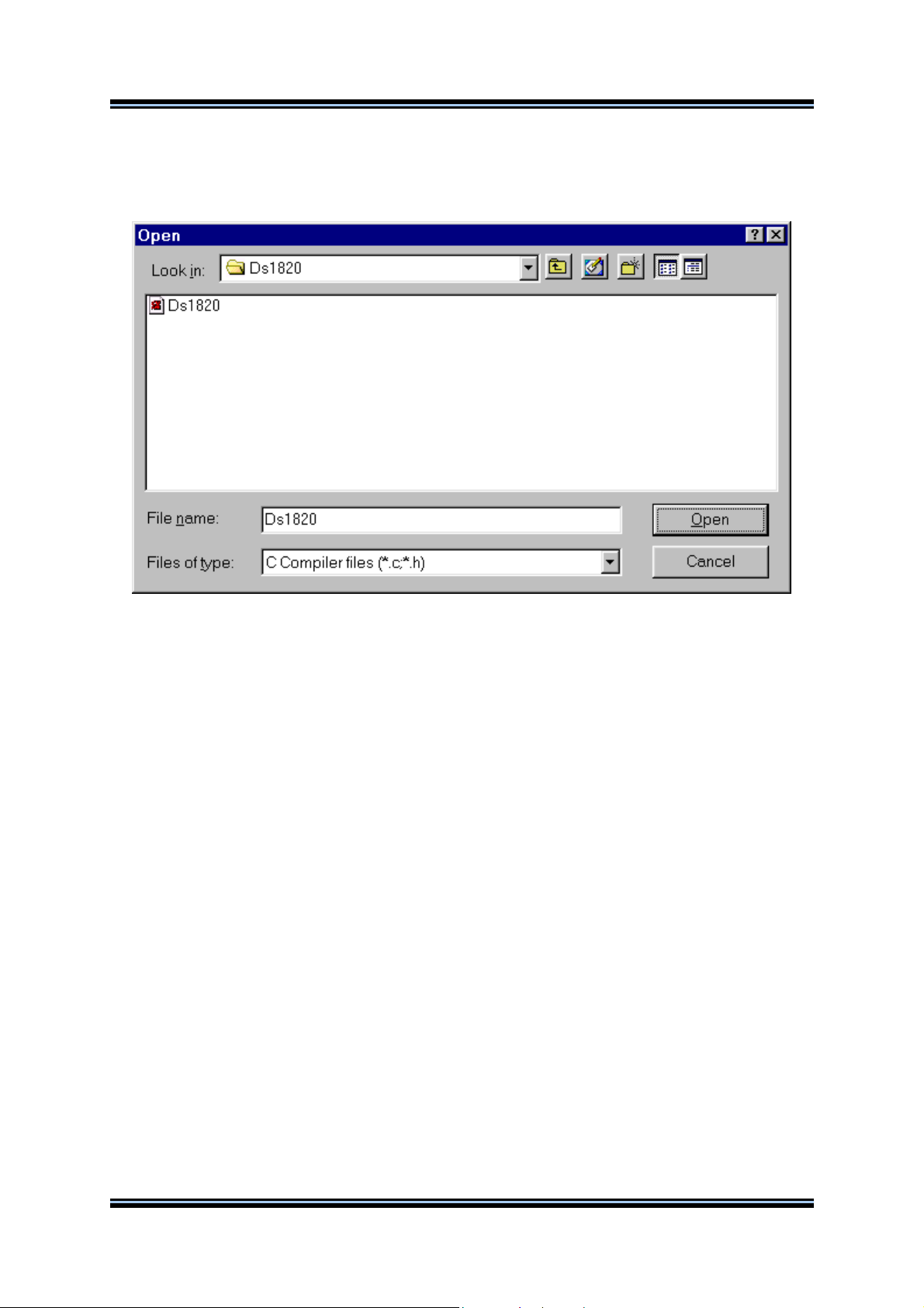
2.1.2 Opening an Existing File
You can open an existing file using the File|Open menu command or by pressing the Open file button
on the toolbar.
An Open dialog window appears.
You must select the name and type of file you wish to open.
By pressing the Open button you will open the file in a new editor window.
2.1.3 Files History
The CodeVisionAVR IDE keeps a history of the opened files.
The most recent eight files that where used can be reopened using the File|Reopen menu command.
© 1998-2003 HP InfoTech S.R.L.
Page 9
Page 11

CodeVisionAVR
2.1.4 Editing a File
A previously opened or a newly created file can be edited in the editor window by using the Tab,
Arrows, Backspace and Delete keys.
Pressing the Home key moves the cursor to the start of the current text line.
Pressing the End key moves the cursor to the end of the current text line.
Pressing the Ctrl+Home keys moves the cursor to the start of the file.
Pressing the Ctrl+End keys moves the cursor to the end of the file.
Portions of text can be selected by dragging with the mouse.
You can copy the selected text to the clipboard by using the Edit|Copy menu command, by pressing
the Ctrl+C keys or by pressing the Copy button on the toolbar.
By using the Edit|Cut menu command, by pressing the Ctrl+X keys or by pressing the Cut button on
the toolbar, you can copy the selected text to the clipboard and then delete it from the file.
Text previously saved in the clipboard can be placed at the current cursor position by using the
Edit|Paste menu command, by pressing the Ctrl+V keys or pressing the Paste button on the toolbar.
Clicking in the right margin of the editor window allows selection of a whole line of text.
Selected text can be deleted using the Edit|Delete menu command or pressing the Ctrl+Delete keys.
The Edit|Print Selection menu command allows the printing of the selected text.
Dragging and dropping with the mouse can move portions of text.
Pressing the Ctrl+Y keys deletes the text line where the caret is currently positioned.
Selected portions of text can be indented, respectively unindented, using the Edit|Indent Block,
respectively Edit|Unindent Block, menu commands or by pressing the Ctrl+I, respectively Ctrl+U
keys.
You can find, respectively replace, portions of text in the edited file by using the Edit|Find,
respectively Edit|Replace, menu commands, by pressing the Ctrl+F, respectively Ctrl+R keys, or by
pressing the Find, respectively Replace buttons on the toolbar.
Changes in the edited text can be undone, respectively redone, by using the Edit|Undo, respectively
Edit|Redo, menu commands, by pressing the Ctrl+Z, respectively Shift+Ctrl+Z keys, or by pressing
the Undo, respectively Redo buttons on the toolbar.
You can go to a specific line number in the edited file, by using the Edit|Goto Line menu command or
by pressing the Alt+G keys.
Bookmarks can be inserted or removed, at the line where the cursor is positioned, by using the
Edit|Toggle Bookmark menu command or by pressing the Shift+Ctrl+0...9 keys.
The Edit|Jump to Bookmark menu command or the Ctrl+0...9 keys will position the cursor at the
start of the corresponding bookmarked text line.
If the cursor is positioned on an opening, respectively closing, brace then the Edit|Match Braces
menu command or the Ctrl+M key will highlight, the portion of text until the corresponding matching
closing, respectively opening brace. Pressing any key or clicking the mouse will hide the highlighting.
Clicking with the mouse right button opens a pop-up menu that also gives the user access to the
above mentioned functions.
© 1998-2003 HP InfoTech S.R.L.
Page 10
Page 12

CodeVisionAVR
2.1.5 Saving a File
The currently edited file can be saved by using the File|Save menu command, by pressing the Ctrl+S
keys or by pressing the Save button on the toolbar.
When saving, the Editor will create a backup file with an ~ character appended to the extension.
All currently opened files can be saved using the File|Save All menu command.
2.1.6 Renaming a File
The currently edited file can be saved under a new name by using the File|Save As menu command.
A Save dialog window will open.
You will have the possibility to specify the new name and type of the file, and eventually its new
location.
© 1998-2003 HP InfoTech S.R.L.
Page 11
Page 13
CodeVisionAVR
2.1.7 Printing a File
You can print the current file using the File|Print menu command or by pressing the Print button on
the toolbar.
The contents of the file will be printed to the Windows default printer.
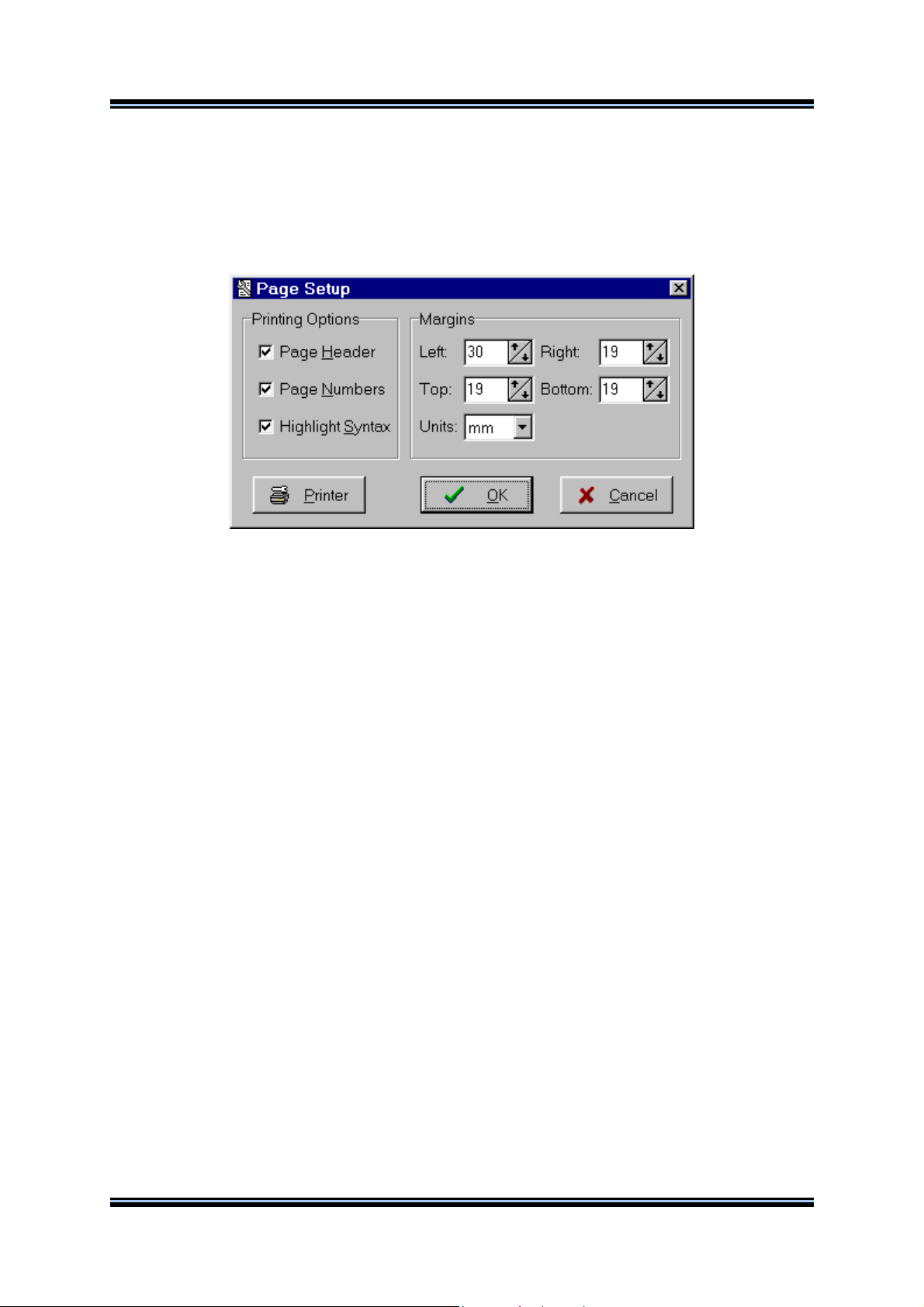
The paper margins used when printing can be set using the File|Page Setup menu command, which
opens the Page Setup dialog window.
The units used when setting the paper margins are specified using the Units list box.
The printer can be configured by pressing the Printer button in this dialog window.
Changes can be saved, respectively canceled, using the OK, respectively Cancel buttons.
© 1998-2003 HP InfoTech S.R.L.
Page 12
Page 14

CodeVisionAVR
2.1.8 Closing a File
You can quit editing the current file by using the File|Close menu command.
If the file was modified, and wasn’t saved yet, you will be prompted if you want to do that.
Pressing Yes will save changes and close the file.
Pressing No will close the file without saving the changes.
Pressing Cancel will disable the file closing process.
All currently opened files can be closed using the File|Close All menu command.
© 1998-2003 HP InfoTech S.R.L.
Page 13
Page 15
CodeVisionAVR
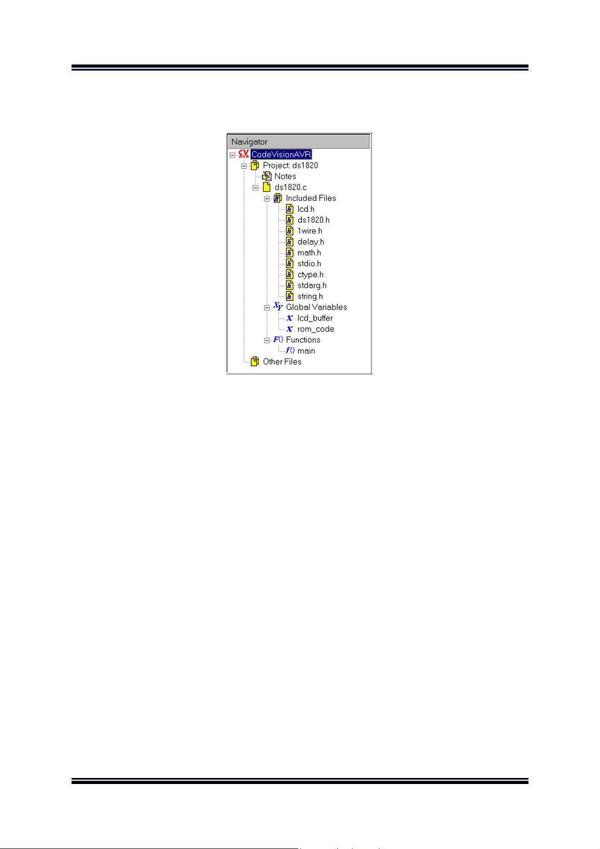
2.1.9 Using the Navigator
The Navigator window allows easy displaying or opening of source files.
By clicking on the file name the appropriate file is maximized or opened.
After a Compile or Make process there is also displayed a list of #include –ed files, global variables
and functions declared in each compiled C source file.
By clicking on the variable’s, respective function’s, name the variable, respective function, declaration
is highlighted in the appropriate C source file.
If during compilation there are errors or warnings, these are also displayed in the Navigator window.
By clicking on the error or warning, the corresponding source line is highlighted in the appropriate file.
The Navigator tree branches can be expanded, respectively collapsed, by clicking on the +,
respectively -, buttons.
By right clicking in the Navigator window you can open a pop-up menu with the following choices:
• Open a file
• Save the currently edited file
• Save All opened files
• Close Current File
• Close Project
• Close All opened files
• Toggle on or off expanding the file branches
• Toggle on or off expanding the Errors and Warnings branches for the file whose Editor window
has focus
© 1998-2003 HP InfoTech S.R.L.
Page 14
Page 16

CodeVisionAVR
2.2 Working with Projects
The Project groups the source file(s) and compiler settings that you use for building a particular
program.
2.2.1 Creating a New Project
You can create a new Project using the File|New menu command or by pressing the Create new file
button on the toolbar.
A dialog box appears, in which you must select File Type|Project and press the OK button.
A dialog will open asking you to confirm if you would like to use the CodeWizardAVR to create the new
project.
If you select No then the Create New Project dialog window will open.
© 1998-2003 HP InfoTech S.R.L.
Page 15
Page 17

CodeVisionAVR
You must specify the new Project file name and its location.
The Project file will have the .prj extension.
You can configure the Project by using the Project|Configure menu command.
© 1998-2003 HP InfoTech S.R.L.
Page 16
Page 18
CodeVisionAVR
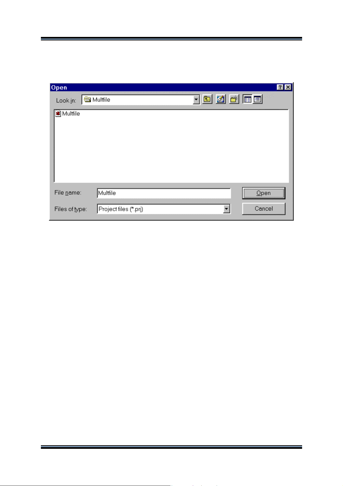
2.2.2 Opening an Existing Project
You can open an existing Project file using the File|Open menu command or by pressing the Open
file button on the toolbar.
An Open dialog window appears.
You must select the file name of the Project you wish to open.
By pressing the Open button you will open the Project file and its source file(s).
You can configure the Project by using the Project|Configure menu command.
© 1998-2003 HP InfoTech S.R.L.
Page 17
Page 19

CodeVisionAVR
2.2.3 Adding Notes or Comments to the Project
With every Project the CodeVisionAVR IDE creates a text file where you can place notes and
comments.
You can access this file using the Project|Notes or Windows menu commands.
This file can be edited using the standard Editor commands.
The file is automatically saved when you Close the Project or Quit the CodeVisionAVR program.
© 1998-2003 HP InfoTech S.R.L.
Page 18
Page 20
CodeVisionAVR
2.2.4 Configuring the Project
The Project can be configured using the Project|Configure menu command or the Project Configure
toolbar button.
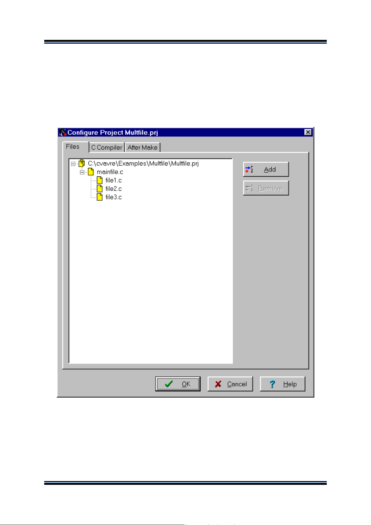
2.2.4.1 Adding or removing a File from the Project
To add or remove a file from the currently opened project you must use the Project|Configure menu
command.
A Configure Project tabbed dialog window will open. You must select the Files tab.
By pressing the Add button you can add a source file to the project.
The first file added to the project is the main project file.
This file will always be Make -ed.
The rest of the files added to the project will be automatically linked to the main project file on Make.
© 1998-2003 HP InfoTech S.R.L.
Page 19
Page 21
CodeVisionAVR
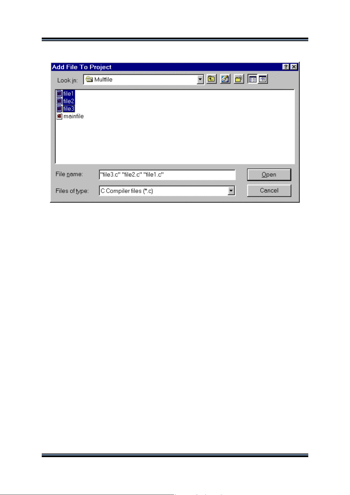
Multiple files can be added by holding the Ctrl key when selecting in the Add File to Project dialog.
When the project is Open-ed all project files will be opened in the editor.
By clicking on a file, and then pressing the Remove button, you will remove this file from the project.
Changes can be saved, respectively canceled, using the OK, respectively Cancel buttons.
When creating a project with multiple files the following rules must be preserved:
• only .C files must be added to the project's Files list
• there's no need to #include the .C files from the Files list as they will be automatically linked
• data type definitions and function declarations must be placed in header .H files, that will be
#include -ed as necessary in the .C files
• global variables declarations must be placed in the .C files where necessary
• there's no need to declare global variables, that are not static, in header .H files, because if these
files will be #include -ed more than once, the compiler will issue errors about variable redeclarations.
© 1998-2003 HP InfoTech S.R.L.
Page 20
Page 22
CodeVisionAVR
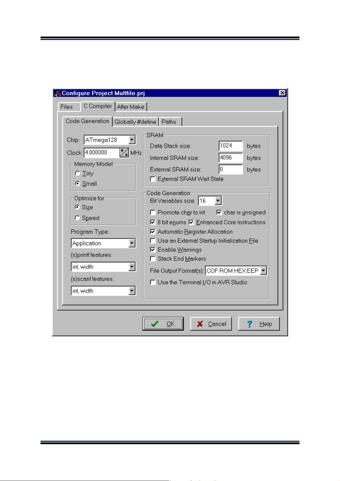
2.2.4.2 Setting the C Compiler Options
To set the C compiler options for the currently opened project you must use the Project|Configure
menu command.
A Configure Project tabbed dialog window will open. You must select the C Compiler and Code
Generation tabs.
You can select the target AVR microcontroller chip by using the Chip combo box.
You must also specify the CPU Clock Frequency in MHz, which is needed by the Delay Functions, 1
Wire Protocol Functions and Dallas Semiconductor DS1820/DS18S20 Temperature Sensors
Functions.
The required memory model can be selected by using the Memory Model radio group box.
The compiled program can be optimized for minimum size, respectively maximum execution speed,
using the Optimize for|Size, respectively Optimize for|Speed, settings.
© 1998-2003 HP InfoTech S.R.L.
Page 21
Page 23
CodeVisionAVR
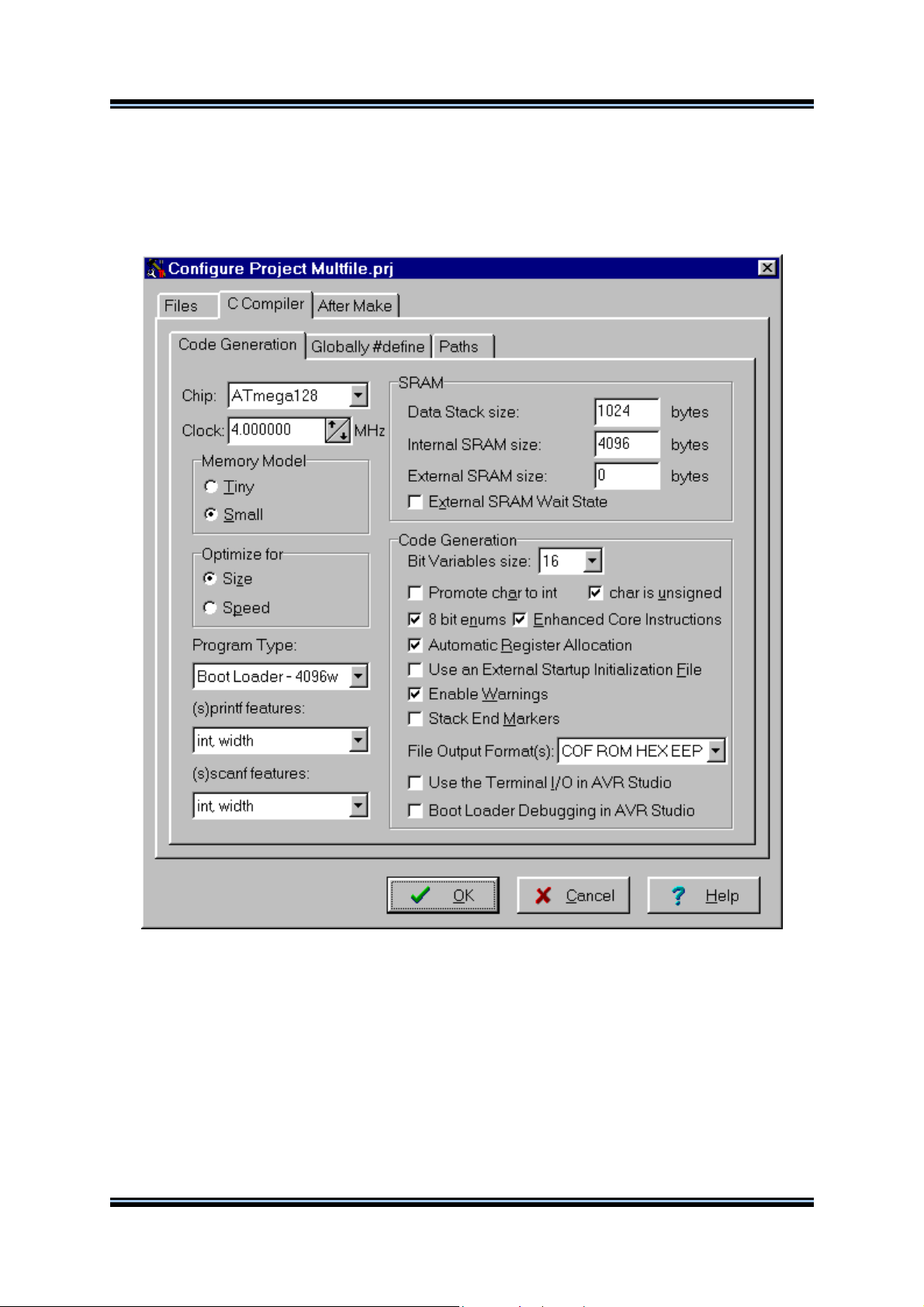
For devices that allow self-programming the Program Type can be selected as:
• Application
• Boot Loader
If the Boot Loader program type was selected, a supplementary Boot Loader Debugging in AVR
Studio option is available.
If this option is enabled, the compiler will generate supplementary code that allows the Boot Loader to
be source level debugged in the AVR Studio simulator/emulator.
When programming the chip with the final Boot Loader code, the Boot Loader Debugging option must
be disabled.
The (s)printf features option allows to select which versions of the printf and sprintf Standard C
Input/Oputput Functions will be linked in your project:
• int - the following conversion type characters are supported: 'c', 's', 'p', 'i', 'd', 'u', 'x', 'X', '%', no
width or precision specifiers are supported, only the '+' and ' ' flags are supported, no input size
modifiers are supported
• int, width - the following conversion type characters are supported: 'c', 's', 'p', 'i', 'd', 'u', 'x', 'X', '%',
the width specifier is supported, the precision specifier is not supported, only the '+', '-', '0' and ' ' flags
are supported, no input size modifiers are supported
© 1998-2003 HP InfoTech S.R.L.
Page 22
Page 24

CodeVisionAVR
• long, width - the following conversion type characters are supported: 'c', 's', 'p', 'i', 'd', 'u', 'x', 'X',
'%' the width specifier is supported, the precision specifier is not supported, only the '+', '-', '0' and ' '
flags are supported, only the 'l' input size modifier is supported
• long, width, precision - the following conversion type characters are supported: 'c', 's', 'p', 'i', 'd',
'u', 'x', 'X', '%', the width and precision specifiers are supported, only the '+', '-', '0' and ' ' flags are
supported, only the 'l' input size modifier is supported
• float, width, precision - the following conversion type characters are supported: 'c', 's', 'p', 'i', 'd',
'u', 'e', 'E', 'f', 'x', 'X', '%', the width and precision specifiers are supported, only the '+', '-', '0' and ' ' flags
are supported, only the 'l' input size modifier is supported.
The more features are selected, the larger is the code size generated for the printf and sprintf
functions.
The (s)scanf features option allows to select which versions of the scanf and sscanf Standard C
Input/Oputput Functions will be linked in your project:
• int, width - the following conversion type characters are supported: 'c', 's', 'i', 'd', 'u', 'x', '%', the
width specifier is supported, no input size modifiers are supported
• long, width - the following conversion type characters are supported: 'c', 's', 'i', 'd', 'u', 'x', '%' the
width specifier is supported, only the 'l' input size modifier is supported.
The more features are selected, the larger is the code size generated for the printf and sprintf
functions.
The Data Stack Size must be also specified.
Eventually you may also specify the External SRAM Size (in case the microcontroller have external
SRAM memory connected).
The External SRAM Wait State option enables the insertion of wait states during access to the
external SRAM. This is useful when using slow memory devices.
© 1998-2003 HP InfoTech S.R.L.
Page 23
Page 25

CodeVisionAVR
If an Atmel AT94K05, AT94K10, AT94K20 or AT94K40 FPSLIC device will be used, than there will be
the possibility to specify the Program SRAM size in Kwords.
The size of the bit variables, which are placed in registers R2 to R14, can be specified using the Bit
Variables size list box.
Checking the Promote char to int check box enables the ANSI promotion of char operands to int.
This option can also be specified using the #pragma promotechar compiler directive.
Promoting char to int leads to increased code size and lower speed for an 8 bit chip microcontroller
like the AVR.
If the char is unsigned check box is checked, the compiler treats by default the char data type as an
unsigned 8 bit in the range 0…255.
If the check box is not checked the char data type is by default a signed 8 bit in the range –128…127.
This option can also be specified using the #pragma uchar compiler directive.
Treating char as unsigned leads to better code size and speed.
If the 8 bit enums check box is checked, the compiler treats the enumerations as being of 8 bit char
data type, leading to improved code size and execution speed of the compiled program. If the check
box is not checked the enumerations are considered as 16 bit int data type as required by ANSI.
© 1998-2003 HP InfoTech S.R.L.
Page 24
Page 26

CodeVisionAVR
The Enhanced Instructions check box allows enabling or disabling the generation of Enhanced Core
instructions for the ATmega128, ATmega16, ATmega161, ATmega162, ATmega163, ATmega32,
ATmega323, ATmega64, ATmega8 and AT94K FPSLIC devices.
The rest of the registers in the range R2 to R14, not used for bit variables, can be automatically
allocated to char and int global variables by checking the Compilation|Automatic Register
Allocation check box.
An external startup file can be used by checking the Compilation|Use an External Startup File
check box.
The generation of warning messages during compilation can be enabled or disabled by using the
Compilation|Enable Warnings check box.
For debugging purposes you have the option Stack End Markers. If you select it, the compiler will
place the strings DSTACKEND, respectively HSTACKEND, at the end of the Data Stack, respectively
Hardware Stack areas.
When you debug the program with the AVR Studio debugger you may see if these strings are
overwritten, and consequently modify the Data Stack Size.
When your program runs correctly you may disable the placement of the strings in order to reduce
code size.
Using the File Output Format(s) list box you can select the following formats for the files generated
by the compiler:
• COFF (required by the Atmel AVR Studio debugger), ROM, Intel HEX and EEP (required by the
In-System Programmer) ;
• Atmel generic OBJ, ROM, Intel HEX and EEP (required by the In-System Programmer).
If the COFF file format is selected and the Use the Terminal I/O in AVR Studio check box is
checked, special debugging information is generated in order to use the AVR Studio 3 Terminal I/O
window for communication with the simulated AVR chip’s UART.
The Use the Terminal I/O in AVR Studio check box must not be checked
does not support this feature.
If the Use the Terminal I/O in AVR Studio option is enabled, the UART or USART code will not run
correctly on the real AVR chip. This option is only for debugging purposes.
for AVR Studio 4, as it
© 1998-2003 HP InfoTech S.R.L.
Page 25
Page 27

CodeVisionAVR
The Globally #define tab allows to #define macros that will be visible in all the project files.
For example:
will be equivalent with placing the definition:
#define ABC 1234
in each project file.
© 1998-2003 HP InfoTech S.R.L.
Page 26
Page 28

CodeVisionAVR
The Paths tabs allows to specify additional paths for #include and library files.
These paths must be entered one per line in the appropriate edit controls.
Changes can be saved, respectively canceled, using the OK, respectively Cancel buttons.
© 1998-2003 HP InfoTech S.R.L.
Page 27
Page 29

CodeVisionAVR
2.2.4.3 Transferring the Compiled Program to the AVR Chip after
Make
This option is available if you select the After Make tab in the Project Configure window.
If you check the Program the Chip option, then after successful compilation/assembly your program
will be automatically transferred to the AVR chip using the built-in Programmer software.
The following steps are executed automatically:
• Chip erasure
• FLASH and EEPROM blank check
• FLASH programming and verification
• EEPROM programming and verification
• Fuse and Lock Bits programming
The Merge data from a .ROM File for FLASH Programming option, if checked, will merge in the
FLASH programming buffer the contents of the .ROM file, created by the compiler after Make, with the
data from the .ROM file specified in .ROM File Path.
This is useful, for example, when adding a boot loader executable compiled in another project, to an
application program that will be programmed in the FLASH memory.
© 1998-2003 HP InfoTech S.R.L.
Page 28
Page 30

CodeVisionAVR
You can select the type of the chip you wish to program using the Chip combo box.
If the chip you have selected has Fuse Bit(s) that may be programmed, then a supplementary Fuse
Bit(s) check box will appear. Using this check box you can set various chip options, which are
described in the Atmel data sheets.
If a Fuse Bit(s) check box is checked
considered as programmed (as per the convention from the Atmel data sheets).
If a Fuse Bits(s) check box is not checked, then the corresponding fuse bit will be set to 1, the fuse
being considered as not programmed.
If you wish to protect your program from copying, you must select the corresponding option using the
FLASH Lock Bits radio box.
If you wish to check the chip's signature before programming you must use the Check Signature
option.
To speed up the programming process you can uncheck the Check Erasure check box.
In this case there will be no verification of the correctness of the FLASH erasure.
The Preserve EEPROM checkbox allows preserving the contents of the EEPROM during chip
erasure.
To speed up the programming process you can uncheck the Verify check box.
In this case there will be no verification of the correctness of the FLASH and EEPROM programming.
Changes can be saved, respectively canceled, using the OK, respectively Cancel buttons.
, then the corresponding fuse bit will be set to 0, the fuse being
© 1998-2003 HP InfoTech S.R.L.
Page 29
Page 31

CodeVisionAVR
2.2.4.4 Running an User Specified Program after Make
This option is available if you select the After Make tab in the Project Configure window.
If you check the Execute User’s Program option, then a program, that you have previously specified,
will be executed after the compilation/assembly process.
© 1998-2003 HP InfoTech S.R.L.
Page 30
Page 32

CodeVisionAVR
Using the Program Settings button you can modify the:
• Program Directory and File Name
• Program Command Line Parameters
• Program Working Directory
Changes can be saved, respectively canceled, using the OK, respectively Cancel buttons.
© 1998-2003 HP InfoTech S.R.L.
Page 31
Page 33
CodeVisionAVR
2.2.5 Obtaining an Executable Program
Obtaining an executable program requires the following steps:
1. Compiling the Project’s C source file, using the CodeVisionAVR C Compiler, and obtaining an
assembler source file
2. Assembling the assembler source file, using the Atmel AVR assembler AVRASM32.
Compiling a File, executes step 1.
Making, executes step 1 and 2 for the main project file
2.2.5.1 Compiling the Project
To compile the Project you must use the Project|Compile File menu command, press the F9 key or
press the Compile button of the toolbar. The CodeVisionAVR C Compiler will be executed, producing
an assembler source file with the .asm extension. This file can be examined and modified by opening
it with the Editor.
The compilation process can be stopped using the Project|Stop Compilation menu command or by
pressing the Stop Compilation button on the toolbar.
After the compilation is complete, an Information window will open showing the compilation results.
© 1998-2003 HP InfoTech S.R.L.
Page 32
Page 34

CodeVisionAVR
Eventual compilation errors and/or warnings will be listed in the Message window located under the
Editor window, or in the Navigator window.
By double clicking on the error or warning message, the line with the problem will be highlighted.
The size of the Message window can be modified using the horizontal slider bar placed between it
and the Editor window.
© 1998-2003 HP InfoTech S.R.L.
Page 33
Page 35

CodeVisionAVR
2.2.5.2 Making the Project
To make the Project you must use the Project|Make menu command, press the Shift+F9 keys or
press the Make button of the toolbar. The CodeVisionAVR C Compiler will be executed, producing an
assembler source file with the .asm extension.
The compilation process can be stopped using the Project|Stop Compilation menu command or by
pressing the Stop Compilation button on the toolbar.
Eventual compilation errors and/or warnings will be listed in the Message window located under the
Editor window, or in the Navigator window.
By double clicking on the error or warning message, the line with the problem will be highlighted.
If no errors were encountered, then the Atmel AVR assembler AVRASM32 will be executed, obtaining
the output file type specified in Project|Configure|C Compiler|Code Generation.
© 1998-2003 HP InfoTech S.R.L.
Page 34
Page 36

CodeVisionAVR
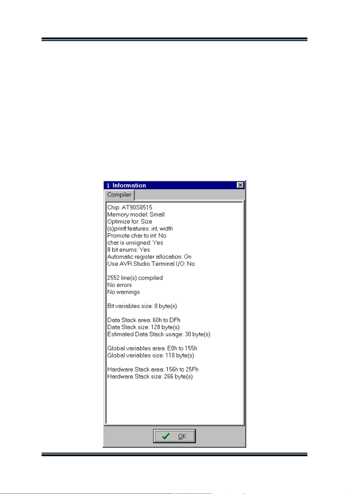
After the make process is completed, an Information window will open showing the compilation
results.
Pressing the Compiler tab will display compilation results.
© 1998-2003 HP InfoTech S.R.L.
Page 35
Page 37

CodeVisionAVR
Pressing the Assembler tab will display assembly results.
© 1998-2003 HP InfoTech S.R.L.
Page 36
Page 38

CodeVisionAVR
Pressing the Programmer tab will display the Chip Programming Counter, which shows how many
times was the AVR chip programmed so far.
Pressing the Set Counter button will open the Set Programming Counter window:
This dialog window allows setting the new Chip Programming Counter value.
Pressing the Program button allows automatic programming of the AVR chip after successful
compilation. Pressing Cancel will disable automatic programming.
© 1998-2003 HP InfoTech S.R.L.
Page 37
Page 39

CodeVisionAVR
2.2.6 Closing a Project
You can quit working with the current Project by using the File|Close Project menu command.
If the Project files were modified, and weren’t saved yet, you will be prompted if you want to do that.
Pressing Yes will save changes and close the project.
Pressing No will close the project without saving the changes.
Pressing Cancel will disable the project closing process.
When saving, the IDE will create a backup file with a .pr~ extension.
© 1998-2003 HP InfoTech S.R.L.
Page 38
Page 40
CodeVisionAVR
2.3 Tools
Using the Tools menu you can execute other programs without exiting the CodeVisionAVR IDE.
2.3.1 The AVR Studio Debugger
The CodeVisionAVR C Compiler is designed to work in conjunction with the Atmel AVR Studio
debugger version 3 and 4.06 (or later).
For the AVR Studio debugger version 4.06 (or later) the compiler will generate an extended
COFF object file that allows watching structures and unions. So it is highly recommended to
use AVR Studio version 4.06 (or later) instead of version 3, which doesn’t support this feature.
AVR Studio 4 prior to version 4.06 does not support the extended COFF object file format, so it
can’t be used with CodeVisionAVR.
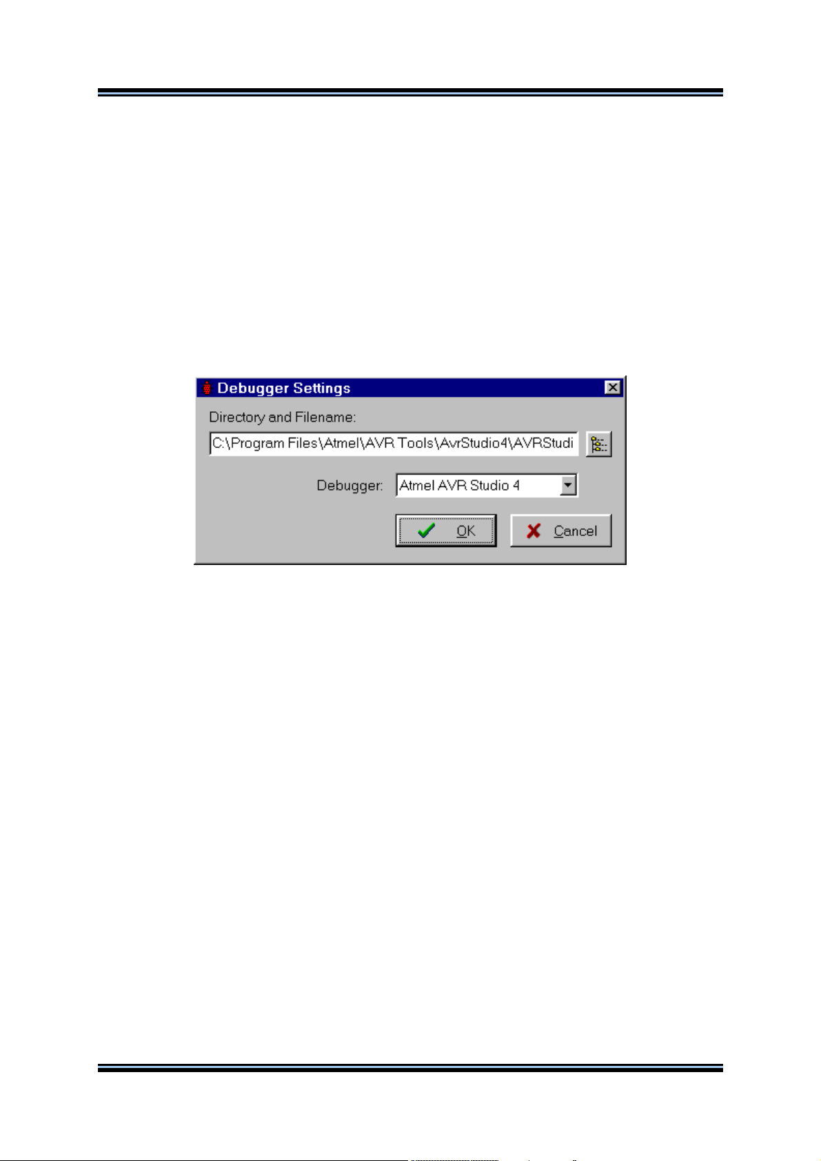
Before you can invoke the debugger, you must first specify its location and file name using the
Settings|Debugger menu command.
The AVR Studio version must be specified in the Debugger list box.
Changes can be saved, respectively canceled, using the OK, respectively Cancel buttons.
The debugger is executed by selecting the Tools|Debugger menu command or by pressing the
Debugger button on the toolbar.
© 1998-2003 HP InfoTech S.R.L.
Page 39
Page 41

CodeVisionAVR
2.3.2 The AVR Chip Programmer
The CodeVisionAVR IDE has a built-in In-System AVR Chip Programmer that lets you easily
transfer your compiled program to the microcontroller for testing.
The Programmer is designed to work with the Atmel STK500/AVRISP/AVRProg (AVR910 application
note), Kanda Systems STK200+/300, Dontronics DT006, Vogel Elektronik VTEC-ISP, Futurlec JRAVR
or the MicroTronics ATCPU/Mega2000 development boards.
The type of the used programmer and the printer port can be selected by using the
Settings|Programmer menu command.
The Programmer is executed by selecting the Tools|Chip Programmer menu command or by
pressing the Chip Programmer button on the toolbar.
You can select the type of the chip you wish to program using the Chip combo box.
If the chip you have selected has Fuse Bit(s) that may be programmed, then a supplementary Fuse
Bit(s) check box will appear. Using this check box you can set various chip options, which are
described in the Atmel data sheets.
If a Fuse Bit(s) check box is checked
considered as programmed (as per the convention from the Atmel data sheets).
If a Fuse Bits(s) check box is not checked, then the corresponding fuse bit will be set to 1, the fuse
being considered as not programmed.
© 1998-2003 HP InfoTech S.R.L.
, then the corresponding fuse bit will be set to 0, the fuse being
Page 40
Page 42
CodeVisionAVR
If you wish to protect your program from copying, you must select the corresponding option using the
FLASH Lock Bits radio box.
The Programmer has two memory buffers:
• The FLASH memory buffer
• The EEPROM memory buffer.
You can Load or Save the contents of these buffers using the File menu.
Supported file formats are:
• Atmel .rom and .eep
• Intel HEX
• Binary .bin
After loading a file in the corresponding buffer, the Start and End addresses are updated accordingly.
You may also edit these addresses if you wish.
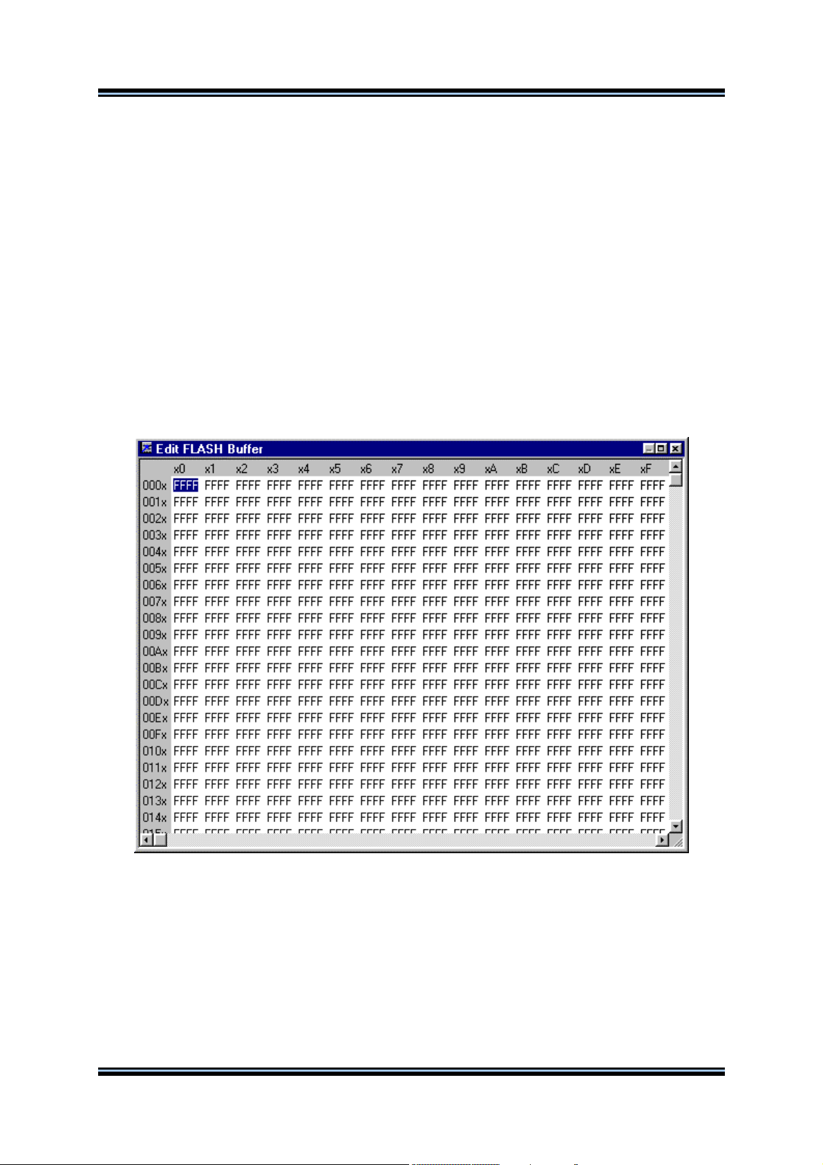
The contents of the FLASH, respectively EEPROM, buffers can be displayed and edited using the
Edit|FLASH , respectively Edit|EEPROM menu commands.
When one of these commands is invoked, an Edit window displaying the corresponding buffer
contents will open:
The buffer's contents, at the highlighted address, can be modified by typing in the new value.
The highlighted address can be modified using the arrow, Tab, Shift+Tab, PageUp or PageDown
keys.
© 1998-2003 HP InfoTech S.R.L.
Page 41
Page 43

CodeVisionAVR
The Fill Memory Block window can be opened by right clicking in the Edit window:
This window lets you specify the Start Address, End Address and Fill Value of the memory area to
be filled.
If you wish to check the chip's signature before any operation you must use the Check Signature
option.
To speed up the programming process you can uncheck the Check Erasure check box.
In this case there will be no verification of the correctness of the FLASH erasure.
The Preserve EEPROM checkbox allows preserving the contents of the EEPROM during chip
erasure.
To speed up the programming process you also can uncheck the Verify check box.
In this case there will be no verification of the correctness of the FLASH and EEPROM programming.
For erasing a chip's FLASH and EEPROM you must select the Program|Erase menu command.
After erasure the chip's FLASH and EEPROM are automatically blank checked.
For simple blank checking you must use the Program|Blank Check menu command.
If you wish to program the FLASH with the contents of the FLASH buffer you must use the
Program|FLASH menu command.
For programming the EEPROM you must use the Program|EEPROM menu command.
After programming the FLASH and EEPROM are automatically verified.
To program the Lock, respectively the Fuse Bit(s) you must use the Program|Fuse Bit(s),
respectively Program|Lock Bits menu commands.
The Program|All menu command allows to automatically:
• Erase the chip
• FLASH and EEPROM blank check
• Program and verify the FLASH
• Program and verify the EEPROM
• Program the Fuse and Lock Bits.
If you wish to read the contents of the chip's FLASH, respectively EEPROM, you must use the
Read|FLASH, respectively Read|EEPROM menu commands.
For reading the chip's signature you must use the Read|Chip Signature menu command.
To read the Lock, respectively the Fuse Bits you must use the Read|Lock Bits,
respectively Read|Fuse Bits menu commands.
For some devices there's also the Read|Calibration Byte(s) option available.
It allows reading the value of the calibration bytes of the chip's internal RC oscillator.
© 1998-2003 HP InfoTech S.R.L.
Page 42
Page 44

CodeVisionAVR
If the programmer is an Atmel STK500, AVRISP or AVRProg (AVR910 application note), then an
additional menu command is present: Read|Programmer's Firmware Version. It allows reading the
major and minor versions of the STK500/AVRISP/AVRProg programmer's firmware.
For comparing the contents of the chip's FLASH, respectively EEPROM, with the corresponding
memory buffer, you must use the Compare|FLASH, respectively Compare|EEPROM menu
commands.
For exiting the Programmer and returning to the CodeVisionAVR IDE you must use the File|Close
menu command.
© 1998-2003 HP InfoTech S.R.L.
Page 43
Page 45

CodeVisionAVR
2.3.3 The Serial Communication Terminal
The Terminal is intended for debugging embedded systems, which employ serial communication
(RS232, RS422, RS485).
The Terminal is invoked using the Tools|Terminal menu command or the Terminal button on the
toolbar.
The characters can be displayed in ASCII or hexadecimal format. The display mode can be toggled
using the Hex/ASCII button.
The received characters can be saved to a file using the Rx File button.
Any characters typed in the Terminal window will be transmitted through the PC serial port.
The entered characters can be deleted using the Backspace key.
By pressing the Send button, the Terminal will transmit a character whose hexadecimal ASCII code
value is specified in the Hex Code edit box.
By pressing the Tx File button, the contents of a file can be transmitted through the serial port.
By pressing the Reset button, the AVR chip on the STK200+/300, VTEC-ISP, DT006, ATCPU or
Mega2000 development board is reseted.
At the bottom of the Terminal window there is a status bar in which are displayed the:
• computer's communication port;
• communication parameters;
• handshaking mode;
• received characters display mode;
• type of emulated terminal;
• the state of the transmitted characters echo setting.
© 1998-2003 HP InfoTech S.R.L.
Page 44
Page 46
CodeVisionAVR
2.3.4 Executing User Programs
User programs are executed by selecting the corresponding command from the Tools menu.
You must previously add the Program’s name to the menu.
2.3.4.1 Configuring the Tools Menu
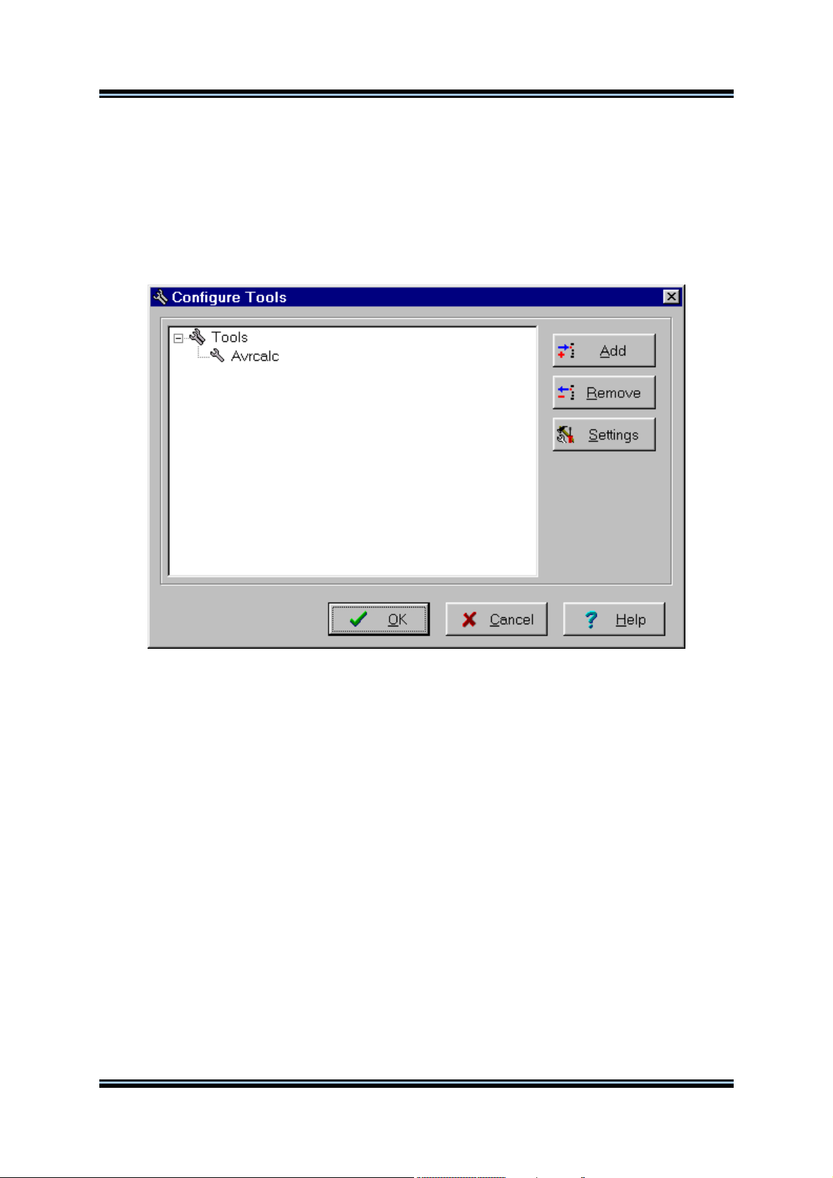
You can add or remove User Programs from the Tools menu by using the Tools|Configure menu
command.
A Configure Tools dialog window, with a list of User Programs, will open.
Using the Add button you can add a Program to the Tools menu.
Using the Remove button you can remove a Program from the Tools menu.
© 1998-2003 HP InfoTech S.R.L.
Page 45
Page 47
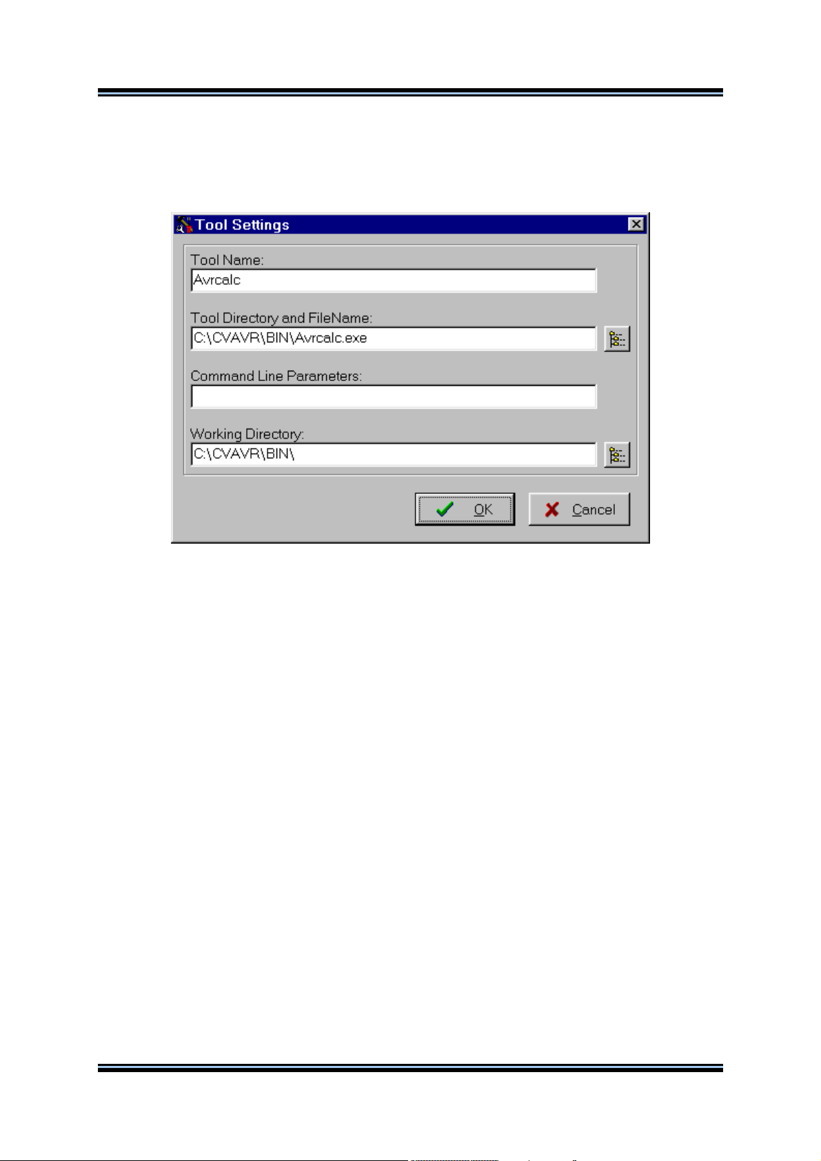
CodeVisionAVR
Using the Settings button you can modify the:
• Tool Menu Name
• Tool Directory and File Name
• Command Line Parameters
• Working Directory of a selected Program from the list.
Changes can be saved, respectively canceled, using the OK, respectively Cancel buttons.
© 1998-2003 HP InfoTech S.R.L.
Page 46
Page 48

CodeVisionAVR
2.4 IDE Settings
The CodeVisionAVR IDE is configured using the Settings menu.
2.4.1 General Settings
The General Settings can be configured using the Settings|General menu command.
If the Show Toolbar check box is checked the command buttons toolbar will be displayed.
If the Show Navigator check box is checked the Navigator window is displayed in the left of the main
program window.
If the Show Information check box is checked, there will be an Information window displayed after
Compiling or Making.
The General Settings changes can be saved, respectively canceled, using the OK, respectively
Cancel buttons.
© 1998-2003 HP InfoTech S.R.L.
Page 47
Page 49

CodeVisionAVR
2.4.2 Configuring the Editor
The Editor can be configured using the Settings|Editor menu command.
By checking or unchecking the Syntax Highlighting check box, you can enable or disable the C
syntax color highlighting of the files displayed in the Editor windows.
By checking or unchecking the Show Line Numbers check box, you can enable or disable the
displaying of the line numbers in the Editor windows.
By checking or unchecking the Autoindent check box, you can enable or disable the autoindenting
during file editing.
The number of blank spaces, inserted when pressing the Tab key, can be specified using the Tab
Size spin edit.
The font, used by the text Editor and the Terminal, can be specified using the Font button.
The different colors, used for displaying the text in the Editor windows and for C syntax highlighting,
can be specified by clicking on the appropriate panels in the Colors group.
The Background and Text color settings are the same for both the EditorEdit File and the
TerminalTerminal.
The Editor configuration changes can be saved, respectively canceled, using the OK, respectively
Cancel buttons.
By pressing the Default button the default Editor settings are restored.
© 1998-2003 HP InfoTech S.R.L.
Page 48
Page 50

CodeVisionAVR
2.4.3 Configuring the Assembler
The Assembler can be configured using the Settings|Assembler menu command.
The On Assembler Error options allow to select which file will be automatically opened by the Editor
in the case of an assembly error.
The Assembler configuration changes can be saved, respectively canceled, using the OK,
respectively Cancel buttons.
© 1998-2003 HP InfoTech S.R.L.
Page 49
Page 51

CodeVisionAVR
2.4.4 Setting the Debugger Path
The CodeVisionAVR C Compiler is designed to work in conjunction with the Atmel AVR Studio
debugger version 3 and 4.06 (or later).
Before you can invoke the debugger, you must first specify its location and file name using the
Settings|Debugger menu command.
The AVR Studio version must be specified in the Debugger list box.
Changes can be saved, respectively canceled, using the OK, respectively Cancel buttons.
Pressing the Browse button opens a dialog window that allows selecting the debugger's directory and
filename.
© 1998-2003 HP InfoTech S.R.L.
Page 50
Page 52
CodeVisionAVR
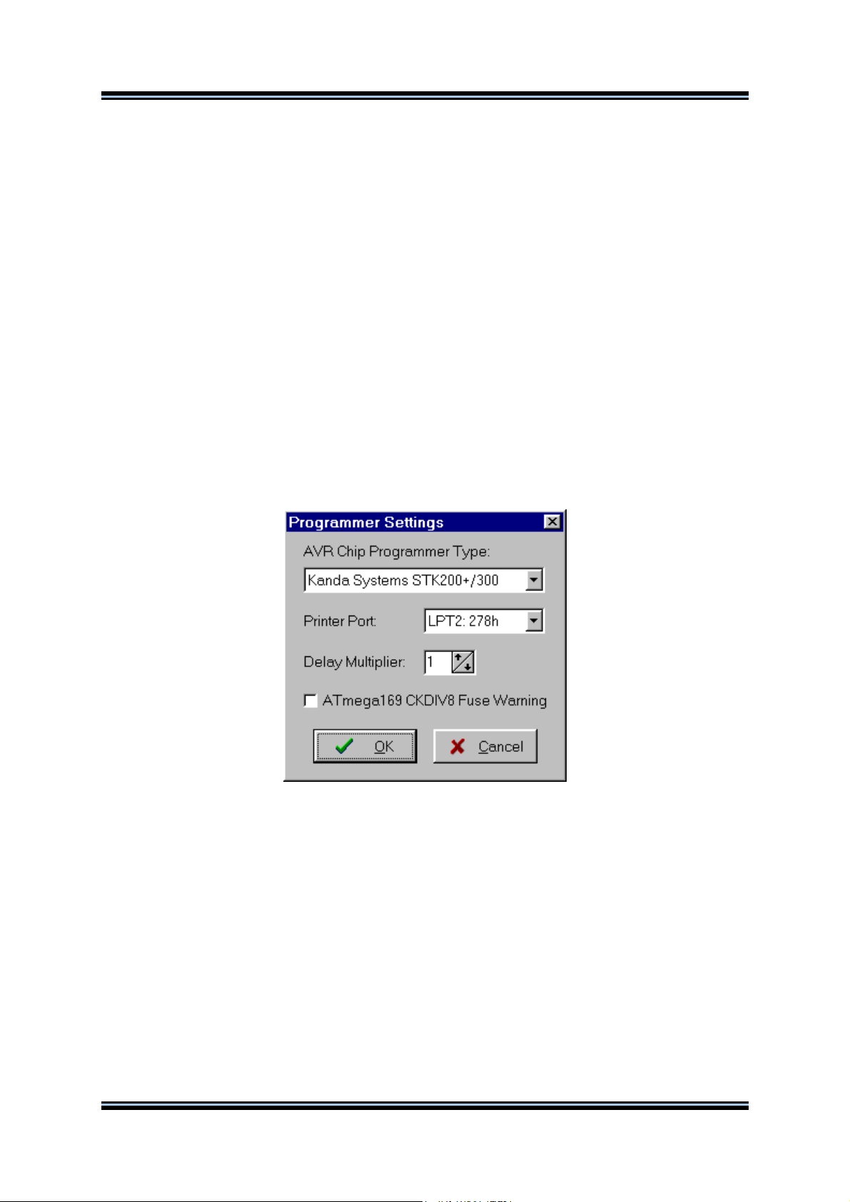
2.4.5 AVR Chip Programmer Setup
Using the Settings|Programmer menu command, you can select the type of the in-system
programmer that is used, and the computer's port to which the programmer is connected.
The current version of CodeVisionAVR supports the following in-system programmers:
• Kanda Systems STK200+ and STK300
• Atmel STK500/AVRISP
• Atmel AVRProg (AVR910 application note)
• Dontronics DT006
• Vogel Elektronik VTEC-ISP
• Futurlec JRAVR
• MicroTronics ATCPU and Mega2000
The STK200+, STK300, DT006, VTEC-ISP, JRAVR, ATCPU and Mega2000 in-system programmers
use the parallel printer port.
The following choices are available through the Printer Port radio group box:
• LPT1, at base address 378h;
• LPT2, at base address 278h;
• LPT3, at base address 3BCh.
The Delay Multiplier value can be increased in case of programming problems on very fast machines.
Of course this will increase overall programming time.
The Atmega169 CKDIV8 Fuse Warning check box, if checked, will enable the generation of a
warning that further low voltage serial programming will be impossible for the Atmega169 Engineering
Samples, if the CKDIV8 fuse will be programmed to 0.
For usual Atmega169 chips this check box must be left unchecked.
© 1998-2003 HP InfoTech S.R.L.
Page 51
Page 53

CodeVisionAVR
The STK500, AVRISP and AVRProg programmers use the RS232C serial communication port, which
can be specified using the Communication Port list box.
Changes can be saved, respectively canceled, using the OK, respectively Cancel buttons.
© 1998-2003 HP InfoTech S.R.L.
Page 52
Page 54

CodeVisionAVR
2.4.6 Serial Communication Terminal Setup
The serial communication Terminal is configured using the Settings|Terminal menu command.
In the Terminal Setup window you can select the:
• computer's communication port used by the Terminal: COM1 to COM6;
• Baud rate used for communication: 110 to 115200;
• number of data bits used in reception and transmission: 5 to 8;
• number of stop bits used in reception and transmission: 1, 1.5 or 2;
• parity used in reception and transmission: None, Odd, Even, Mark or Space;
• type of emulated terminal: TTY, VT52 or VT100;
type of handshaking used in communication: None, Hardware (CTS or DTR) or Software
•
(XON/XOFF);
• • possibility to append LF characters after CR characters on reception and transmission;
enabling or disabling the echoing of the transmitted characters.
Changes can be saved, respectively canceled, using the OK, respectively Cancel buttons.
© 1998-2003 HP InfoTech S.R.L.
Page 53
Page 55

CodeVisionAVR
2.5 Accessing the Help
CodeVisionAVR help system is accessed by invoking the Help|Help menu command or by pressing
the Help toolbar button.
2.6 Transferring the License to another computer
The CodeVisionAVR C compiler features a computer locked licensing system.
This means that, the first time after purchase, you will receive from the author a license file that is
specific to your particular computer.
This prevents you from using the software on another computer, until you will Export the license to
this computer.
After the license Export, the compiler on the first computer will be disabled and you will only be able
to run the compiler on the second one.
You can always Export the license back to the first computer, but the license on the second one will
be disabled after that.
By this procedure only one person can use the compiler at a time.
To Export the license from the computer #1 to the computer #2 you must proceed like this:
• install the CodeVisionAVR C compiler on the computer #2
• execute the compiler on computer #2, it will display a specific serial number
© 1998-2003 HP InfoTech S.R.L.
Page 54
Page 56

CodeVisionAVR
• execute the compiler on computer #1 and select the Help|Export menu command, an Export
CodeVisionAVR License dialog window will open
• enter the serial number from computer #2 in the Destination Serial Number edit box
• press the Export button, if you press the Cancel button the Export will be canceled
• you will be prompted where to place the new license file for the computer #2, usually you can
chose a diskette in drive A:
• press Save. After the new license file is successfully copied to the diskette, the compiler on
computer #1 will cease running
© 1998-2003 HP InfoTech S.R.L.
Page 55
Page 57

CodeVisionAVR
• place the diskette with the license file in drive A: of computer #2 and press the Import button.
After that the license transfer is completed and the compiler will run only on computer #2.
Please note that after the Export procedure, the serial number of the computer #1 will change.
In this situation when you will try to Import a license back to this computer, you must enter this new
serial number, not the old one.
© 1998-2003 HP InfoTech S.R.L.
Page 56
Page 58

CodeVisionAVR
2.7 Connecting to HP InfoTech's Web Site
The Help|HP InfoTech on the Web menu command opens the default web browser and connects to
HP InfoTech's web site http://www.hpinfotech.ro
Here you can check for the latest HP InfoTech's products and updates to CodeVisionAVR.
2.8 Contacting HP InfoTech by E-Mail
The Help|E-Mail HP InfoTech menu command opens the default e-mail program and allows you to
send an e-mail to: office@hpinfotech.ro
2.9 Quitting the CodeVisionAVR IDE
To quit working with the CodeVisionAVR IDE you must select the File|Exit menu command.
If some source files were modified and were not saved yet, you will be prompted if you want to do that.
© 1998-2003 HP InfoTech S.R.L.
Page 57
Page 59

CodeVisionAVR
3. CodeVisionAVR C Compiler Reference
This section describes the general syntax rules for the CodeVisionAVR C compiler.
Only specific aspects regarding the implementation of the C language by this compiler are exposed.
This help is not intended to teach you the C language; you can use any good programming book to do
that.
You must also consult the appropriate AVR data sheets from Atmel.
3.1 The Preprocessor
The Preprocessor directives allows you to:
• include text from other files, such as header files containing library and user function prototypes
• define macros that reduce programming effort and improve the legibility of the source code
• set up conditional compilation for debugging purposes and to improve program portability
• issue compiler specific directives
The #include directive may be used to include another file in your source.
You may nest as many as 16 #include files.
Example:
/* File will be looked for in the /inc directory of the compiler. */
#include <file_name>
or
/* File will be looked for in the current project directory.
If it's not located there, then it will be included from
the /inc directory of the compiler. */
#include "file_name"
The #define directive may be used to define a macro.
Example:
#define ALFA 0xff
This statement defines the symbol ‘ALFA’ to the value 0xff.
The C preprocessor will replace 'ALFA' with 0xff in the source text before compiling.
Macros can also have parameters. The preprocessor will replace the macro with it's expansion and
the formal parameters with the real ones.
Example:
#define SUM(a,b) a+b
/* the following code sequence will be replaced with int i=2+3; */
int i=SUM(2,3);
When defining macros you can use the # operator to convert the macro parameter to a character
string.
Example:
#define PRINT_MESSAGE(t) printf(#t)
/* ...... */
/* the following code sequence will be replaced with printf("Hello"); */
PRINT_MESSAGE(Hello);
© 1998-2003 HP InfoTech S.R.L.
Page 58
Page 60

CodeVisionAVR
Two parameters can be concatenated using the ## operator.
Example:
#define ALFA(a,b) a ## b
/* the following code sequence will be replaced with char xy=1; */
char ALFA(x,y)=1;
A macro definition can be extended to a new line by using \ .
Example:
#define MESSAGE "This is a very \
long text..."
A macro can be undefined using the #undef directive.
Example:
#undef ALFA
The #ifdef, #ifndef, #else and #endif directives may be used for conditional compilation.
The syntax is:
#ifdef macro_name
[set of statements 1]
#else
[set of statements 2]
#endif
If 'alfa' is a defined macro name, then the #ifdef expression evaluates to true and the set of
statements 1 will be compiled.
Otherwise the set of statements 2 will be compiled.
The #else and set of statements 2 are optional.
If 'alfa' is not defined, the #ifndef expression evaluates to true.
The rest of the syntax is the same as that for #ifdef.
The #if, #elif, #else and #endif directives may be also used for conditional compilation.
#if expression1
[set of statements 1]
#elif expression2
[set of statements 2]
#else
[set of statements 3]
#endif
If expression1 evaluates to true, the set of statements 1 will be compiled.
If expression2 evaluates to true, the set of statements 2 will be compiled.
Otherwise the set of statements 3 will be compiled.
The #else and set of statements 3 are optional.
© 1998-2003 HP InfoTech S.R.L.
Page 59
Page 61

CodeVisionAVR
There are the following predefined macros:
__CODEVISIONAVR__ the version and revision of the compiler represented as an integer,
example for V1.23.8 this will be 1238
__LINE__ the current line number of the compiled file
__FILE__ the current compiled file
__TIME__ the current time in hh:mm:ss format
__DATE__ the current date in mmm dd yyyy format
_CHIP_ATXXXXX_ where ATXXXXX is the chip type, in uppercase letters, specified in the
Project|Configure|C Compiler|Code Generation|Chip option
_MCU_CLOCK_FREQUENCY_ the AVR clock frequency specified in the Project|Configure|C
Compiler|Code Generation|Clock option, expressed as an integer in Hz
_MODEL_TINY_ if the program is compiled using the TINY memory model
_MODEL_SMALL_ if the program is compiled using the SMALL memory model
_OPTIMIZE_SIZE_ if the program is compiled with optimization for size
_OPTIMIZE_SPEED_ if the program is compiled with optimization for speed
_UNSIGNED_CHAR_ if the Project|Configure|C Compiler|Code Generation|char is unsigned
compiler option is enabled or #pragma uchar+ is used
_8BIT_ENUMS_ if the Project|Configure|C Compiler|Code Generation|8 bit enums compiler
option is enabled or #pragma 8bit_enums+ is used.
The #line directive can be used to modify the predefined __LINE__ and __FILE__ macros.
The syntax is:
#line integer_constant ["file_name"]
Example:
/* This will set __LINE__ to 50 and
__FILE__ to "file2.c" */
#line 50 "file2.c"
/* This will set __LINE__ to 100 */
#line 100
There #error directive can be used to stop compilation and display an error message.
The syntax is:
#error error_message
Example:
#error This is an error!
The #pragma directive allows compiler specific directives.
You can use the #pragma warn directive to enable or disable compiler warnings.
Example:
/* Warnings are disabled */
#pragma warn-
/* Write some code here */
/* Warnings are enabled */
#pragma warn+
© 1998-2003 HP InfoTech S.R.L.
Page 60
Page 62

CodeVisionAVR
The compiler’s code optimizer can be turned on or off using the #pragma opt directive. This directive
must be placed at the start of the source file.
The default is optimization turned on.
Example:
/* Turn optimization off, for testing purposes */
#pragma opt-
or
/* Turn optimization on */
#pragma opt+
If the code optimization is enabled, you can optimize some portions or all the program for size or
speed using the #pragma optsize directive.
The default state is determined by the Project|Configure|C Compiler|Code
Generation|Optimization menu setting. Example:
/* The program will be optimized for minimum size */
#pragma optsize+
/* Place your program functions here */
/* Now the program will be optimized for maximum execution speed */
#pragma optsize-
/* Place your program functions here */
The automatic saving and restoring of registers R0, R1, R15, R22, R23, R24, R25, R26, R27, R30,
R31 and SREG, during interrupts can be turned on or off using the #pragma savereg directive.
Example:
/* Turn registers saving off */
#pragma savereg-
/* interrupt handler */
interrupt [1] void my_irq(void) {
/* now save only the registers that are affected by the routines in the
handler, for example R30, R31 and SREG */
#asm
push r30
push r31
in r30,SREG
push r30
#endasm
/* place the C code here */
/* now restore SREG, R31 and R30 */
#asm
pop r30
out SREG,r30
pop r31
pop r30
#endasm
}
/* re-enable register saving for the other interrupts */
#pragma savereg+
The default state is automatic saving of registers during interrupts.
© 1998-2003 HP InfoTech S.R.L.
Page 61
Page 63

CodeVisionAVR
The automatic allocation of global variables to registers can be turned on or off using the #pragma
regalloc directive.
The default state is determined by the Project|Configure|C Compiler|Code Generation|Automatic
Register Allocation check box.
Example:
/* the following global variable will be automatically
allocated to a register */
#pragma regalloc+
unsigned char alfa;
/* the following global variable will not be automatically
allocated to a register and will be placed in normal SRAM */
#pragma regallocunsigned char beta;
The ANSI char to int operands promotion can be turned on or off using the #pragma promotechar
directive.
Example:
/* turn on the ANSI char to int promotion */
#pragma promotechar+
/* turn off the ANSI char to int promotion */
#pragma promotechar-
This option can also be specified in the Project|Configure|C Compiler|Code Generation|Promote
char to int menu.
Treating char by default as an unsigned 8 bit can be turned on or off using the #pragma uchar
directive.
Example:
/* char will be unsigned by default */
#pragma uchar+
/* char will be signed by default */
#pragma uchar-
This option can also be specified in the Project|Configure|C Compiler|Code Generation|char is
unsigned menu.
The #pragma library directive is used for specifying the necessity to compile/link a specific library file.
Example:
#pragma library mylib.lib
The #pragma glbdef+ directive is used for compatibility with projects, created with versions of
CodeVisionAVR prior to V1.0.2.2, where the Project|Configure|C Compiler|Global #define option
was enabled.
It signals the compiler that macros are globally visible in all the program modules of a project.
This directive must be placed in beginning of the first source file of the project.
By default this directive is not active, so macros are visible only in the program module where they are
defined.
© 1998-2003 HP InfoTech S.R.L.
Page 62
Page 64

CodeVisionAVR
3.2 Comments
The character string "/*" marks the beginning of a comment.
The end of the comment is marked with "*/".
Example:
/* This is a comment */
/* This is a
multiple line comment */
One-line comments may be also defined by using the string "//".
Example:
// This is also a comment
Nested comments are not allowed.
© 1998-2003 HP InfoTech S.R.L.
Page 63
Page 65

CodeVisionAVR
3.3 Reserved Keywords
Following is a list of keywords reserved by the compiler.
These can not be used as identifier names.
break
bit
case
char
const
continue
default
defined
do
double
eeprom
else
enum
extern
flash
float
for
funcused
goto
if
inline
int
interrupt
long
register
return
short
signed
sizeof
sfrb
sfrw
static
struct
switch
typedef
union
unsigned
void
volatile
while
© 1998-2003 HP InfoTech S.R.L.
Page 64
Page 66

CodeVisionAVR
3.4 Identifiers
An identifier is the name you give to a variable, function, label or other object.
An identifier can contain letters (A...Z, a...z) and digits (0...9), as well as the underscore character (_).
However an identifier can only start with a letter or an underscore.
Case is significant; i.e. variable1 is not the same as Variable1.
Identifiers can have up to 32 characters.
3.5 Data Types
The following table lists all the data types supported by the CodeVisionAVR C compiler, their range of
possible values and their size:
Type Size (Bits) Range
bit 1 0 , 1
char 8 -128 to 127
unsigned char 8 0 to 255
signed char 8 -128 to 127
int 16 -32768 to 32767
short int 16 -32768 to 32767
unsigned int 16 0 to 65535
signed int 16 -32768 to 32767
long int 32 -2147483648 to 2147483647
unsigned long int 32 0 to 4294967295
signed long int 32 -2147483648 to 2147483647
float 32 ±1.175e-38 to ±3.402e38
double 32 ±1.175e-38 to ±3.402e38
The bit data type is supported only for global variables.
If the Project|Configure|C Compiler|Code Generation|char is unsigned option is checked or
#pragma uchar+ is used, then char has by default the range 0..255.
© 1998-2003 HP InfoTech S.R.L.
Page 65
Page 67

CodeVisionAVR
3.6 Constants
Integer or long integer constants may be written in decimal form (e.g. 1234), in binary form with 0b
prefix (e.g. 0b101001), in hexadecimal form with 0x prefix (e.g. 0xff) or in octal form with 0-prefix (e.g.
0777).
Unsigned integer constants may have the suffix U (e.g. 10000U).
Long integer constants may have the suffix L (e.g. 99L).
Unsigned long integer constants may have the suffix UL (e.g. 99UL).
Floating point constants may have the suffix F (e.g. 1.234F).
Character constants must be enclosed in single quotation marks. E.g. 'a'.
String constants must be enclosed in double quotation marks. E.g. "Hello world".
If you place a string between quotes as a function parameter, this string will automatically be
considered as constant and will be placed in FLASH memory.
Example:
/ * this function displays a string located in SRAM */
void display_ram(char *s) {
/* ....... */
}
/ * this function displays a string located in FLASH */
void display_flash(char flash *s) {
/* ....... */
}
void main(void) {
/* this will not work !!! */
/* because the function addresses the string as */
/* it is located in SRAM, but the string "Hello world" */
/* is constant and is placed in FLASH */
display_ram("Hello world");
/* this will work !!! */
/* the function addresses the string as it is located in FLASH */
display_flash("Hello world");
}
Constant can be grouped in arrays, which can have up to 8 dimensions.
Constants are stored in FLASH memory, to specify this you must use the flash or const keywords.
Constant expressions are automatically evaluated during compilation.
Example:
flash int integer_constant=1234+5;
flash char char_constant=’a’;
flash long long_int_constant1=99L;
flash long long_int_constant2=0x10000000;
flash int integer_array1[]={1,2,3};
/* The first two elements will be 1 and 2,
the rest will be 0 */
flash int integer_array2[10]={1,2};
flash int multidim_array[2,3]={{1,2,3},{4,5,6}};
flash char string_constant1[]=”This is a string constant”;
const char string_constant2[]=”This is also a string constant”;
Constants can’t be declared inside functions.
© 1998-2003 HP InfoTech S.R.L.
Page 66
Page 68

CodeVisionAVR
3.7 Variables
Program variables can be global (accessible to all the functions in the program) or local (accessible
only inside the function they are declared).
If not specifically initialized, the global variables are automatically set to 0 at program startup.
The local variables are not automatically initialized on function call.
The syntax is:
[<storage modifier>] <type definition> <identifier>;
Example:
/* Global variables declaration */
char a;
int b;
/* and initialization */
long c=1111111;
void main(void) {
/* Local variables declaration */
char d;
int e;
/* and initialization */
long f=22222222;
}
Variables can be grouped in arrays, which can have up to 8 dimensions.
The first element of the array has always the index 0.
If not specifically initialized, the elements of global variable arrays are automatically set to 0 at
program startup.
Example:
/* All the elements of the array will be 0 */
int global_array1[32];
/* Array is automatically initialized */
int global_array2[]={1,2,3};
int global_array3[4]={1,2,3,4};
char global_array4[]=”This is a string”;
/* Only the first 3 elements of the array are
initialized, the rest 29 will be 0 */
int global_array5[32]={1,2,3};
/* Multidimensional array */
int multidim_array[2][3]={{1,2,3},{4,5,6}};
void main(void) {
/* local array declaration */
int local_array1[10];
/* local array declaration and initialization */
int local_array2[3]={11,22,33};
char local_array3[7]="Hello";
}
© 1998-2003 HP InfoTech S.R.L.
Page 67
Page 69

CodeVisionAVR
Local variables that must conserve their values during different calls to a function must be declared as
static. Example:
int alfa(void) {
/* declare and initialize the static variable */
static int n=1;
return n++;
}
void main(void) {
int i;
/* the function will return the value 1 */
i=alfa();
/* the function will return the value 2 */
i=alfa();
}
If not specifically initialized, static variables are automatically set to 0 at program startup.
Variables that are declared in other files must be preceded by the extern keyword.
Example:
extern int xyz;
/* now include the file which contains
the variable xyz definition */
#include <file_xyz.h>
To instruct the compiler to allocate a variable to registers, the register modifier must be used.
Example:
register int abc;
The compiler may automatically allocate a variable to registers, even if this modifier is not used.
The volatile modifier must be used in order to prevent a variable to be allocated to registers and to
warn the compiler that it may be subject to outside change during evaluation.
Example:
volatile int abc;
All the global variables, not allocated to registers, are stored in the Global Variables area of SRAM.
All the local variables, not allocated to registers, are stored in dynamically allocated space in the Data
Stack area of SRAM.
© 1998-2003 HP InfoTech S.R.L.
Page 68
Page 70

CodeVisionAVR
3.7.1 Specifying the SRAM Storage Address for Global Variables
Global variables can be stored at specific SRAM locations at design-time using the @ operator.
Example:
/* the integer variable "a" is stored
in SRAM at address 80h */
int a @0x80;
/* the structure "alfa" is stored
in SRAM at address 90h */
struct x {
int a;
char c;
} alfa @0x90;
3.7.2 Bit Variables
The bit variables are special global variables located in the register GPIOR and R2 to R14 memory
space.
These variables are declared using the bit keyword.
The syntax is:
bit <identifier>;
Example:
/* declaration and initialization for an ATtiny2313 chip
which has GPIOR0, GPIOR1 and GPIOR2 registers */
bit alfa=1; /* bit0 of GPIOR0 */
bit beta; /* bit1 of GPIOR0 */
void main(void)
{
if (alfa) beta=!beta;
/* ........ */
}
Memory allocation for the bit variables is done, in the order of declaration, starting with bit 0 of
GPIOR0, then bit 1 of GPIOR0 and so on, in ascending order.
After all the GPIOR registers are allocated, further bit variables are allocated in R2 up to R14.
If the chip does not have GPIOR registers, the allocation begins directly from register R2.
The size of the bit variables allocated to the program can be specified in the Project|Configure|C
Compiler|Code Generation|Bit Variables Size list box.
This size should be as low as possible, in order to free registers for allocation to other global variables.
If not specifically initialized, the bit global variables are automatically set to 0 at program startup.
In expression evaluation bit variables are automatically promoted to unsigned char.
© 1998-2003 HP InfoTech S.R.L.
Page 69
Page 71

CodeVisionAVR
3.7.3 Allocation of Variables to Registers
In order to fully take advantage of the AVR architecture and instruction set, the compiler allocates
some of the program variables to chip registers.
The registers from R2 up to R14 can be allocated for bit variables.
You may specify how many registers in this range are allocated using the Project|Configure|C
Compiler|Code Generation|Bit Variables Size list box. This value must be as low as required by the
program.
If the Project|Configure|C Compiler|Code Generation|Automatic Register Allocation option is
checked or the #pragma regalloc+ compiler directive is used, the rest of registers in the R2 to R14
range, that aren’t used for bit variables, are allocated to char and int global variables. The allocation
is realized in order of variable declaration until the R14 register is allocated.
If the automatic register allocation is disabled, you can use the register keyword to specify which
global variable to be allocated to registers.
Example:
/* disable automatic register allocation */
#pragma regalloc/* allocate the variable ‘alfa’ to a register */
register int alfa;
/* allocate the variable ‘beta’ to the register pair R10, R11 */
register int beta @10;
The char and int local variables are automatically allocated, in order of declaration, to registers R16
up to R21.
© 1998-2003 HP InfoTech S.R.L.
Page 70
Page 72

CodeVisionAVR
3.7.4 Structures
Structures are user-defined collections of named members.
The structure members can be any of the supported data types, arrays of these data types or pointers
to them.
Structures are defined using the struct reserved keyword.
The syntax is:
[<storage modifier>] struct [<structure tag-name>] {
[<type> <variable-name>[,<variable-name>, ...]];
[<type> [<bitfield-id>]:<width>[,[<bitfield-id>]:<width>, ...]];
...
} [<structure variables>];
Example:
/* Global structure located in SRAM */
struct ram_structure {
char a,b;
int c;
char d[30],e[10];
char *pp;
} sr;
/* Global constant structure located in FLASH */
flash struct flash_structure {
int a;
char b[30], c[10];
} sf;
/* Global structure located in EEPROM */
eeprom struct eeprom_structure {
char a;
int b;
char c[15];
} se;
void main(void) {
/* Local structure */
struct local_structure {
char a;
int b;
long c;
} sl;
/* ............. */
}
The space allocated to the structure in memory is equal to sum of the sizes of all the members.
There are some restrictions that apply to the structures stored in FLASH and EEPROM.
Due to the fact that pointers must be always located in SRAM, they can't be used in these structures.
Because with the Atmel AVRASM32 Assembler single bytes defined with .DB in FLASH occupy in
reality 2 bytes, the CodeVisionAVR C compiler will replace the char members of structures stored in
FLASH with int.
Also it will extend the size of the char arrays, members of such structures, to an even value.
© 1998-2003 HP InfoTech S.R.L.
Page 71
Page 73

CodeVisionAVR
Structures can be grouped in unidimensional arrays.
Example how to initialize and access an global structure array stored in EEPROM:
/* Global structure array located in EEPROM */
eeprom struct eeprom_structure {
char a;
int b;
char c[15];
} se[2]={{'a',25,"Hello"},
{'b',50,"world"}};
void main(void) {
char k1,k2,k3,k4;
int i1, i2;
/* define a pointer to the structure */
struct eeprom_structure eeprom *ep;
/* direct access to structure members */
k1=se[0].a;
i1=se[0].b;
k2=se[0].c[2];
k3=se[1].a;
i2=se[1].b;
k4=se[1].c[2];
/* same access to structure members using a pointer */
ep=&se; /* initialize the pointer with the structure address */
k1=ep->a;
i1=ep->b;
k2=ep->c[2];
++ep; /* increment the pointer */
k3=ep->a;
i2=ep->b;
k4=ep->c[2];
}
Because some AVR devices have a small amount of SRAM, in order to keep the size of the Data
Stack small, it is recommended not to pass structures as function parameters and use pointers for this
purpose.
Example:
struct alpha {
int a,b, c;
} s={2,3};
/* define the function */
struct alpha *sum_struct(struct alpha *sp) {
/* member c=member a + member b */
sp->c=sp->a + sp->b;
/* return a pointer to the structure */
return sp;
}
void main(void) {
int i;
/* s->c=s->a + s->b */
/* i=s->c */
i=sum_struct(&s)->c;
}
© 1998-2003 HP InfoTech S.R.L.
Page 72
Page 74

CodeVisionAVR
Structure members can be also declared as bit fields, having a width from 1 to 32.
Bit fields are allocated in the order of declaration starting from the least significant bit.
Example:
/* this structure will occupy 1 byte in SRAM
as the bit field data type is unsigned char */
struct alpha1 {
unsigned char a:1; /* bit 0 */
unsigned char b:4; /* bits 1..4 */
unsigned char c:3; /* bits 5..7 */
};
/* this structure will occupy 2 bytes in SRAM
as the bit field data type is unsigned int */
struct alpha2 {
unsigned int a:2; /* bits 0..1 */
unsigned int b:8; /* bits 2..9 */
unsigned int c:4; /* bits 10..13 */
/* bits 14..15 are not used */
};
/* this structure will occupy 4 bytes in SRAM
as the bit field data type is unsigned long */
struct alpha3 {
unsigned long a:10; /* bits 0..9 */
unsigned long b:8; /* bits 10..17 */
unsigned long c:6; /* bits 18..23 */
/* bits 24..31 are not used */
};
© 1998-2003 HP InfoTech S.R.L.
Page 73
Page 75

CodeVisionAVR
3.7.5 Unions
Unions are user-defined collections of named members that share the same memory space.
The union members can be any of the supported data types, arrays of these data types or pointers to
them.
Unions are defined using the union reserved keyword.
The syntax is:
[<storage modifier>] union [<union tag-name>] {
[<type> <variable-name>[,<variable-name>, ...]];
[<type> <bitfield-id>:<width>[,<bitfield-id>:<width>, ...]];
...
} [<union variables>];
Unions are always stored in SRAM.
The space allocated to the union in memory is equal to the size of the largest member.
Union members can be accessed in the same way as structure members. Example:
/* union declaration */
union alpha {
unsigned char lsb;
unsigned int word;
} data;
void main(void) {
unsigned char k;
/* define a pointer to the union */
union alpha *dp;
/* direct access to union members */
data.word=0x1234;
k=data.lsb; /* get the LSB of 0x1234 */
/* same access to union members using a pointer */
dp=&data; /* initialize the pointer with the union address */
dp->word=0x1234;
k=dp->lsb; /* get the LSB of 0x1234 */
}
Because some AVR devices have a small amount of SRAM, in order to keep the size of the Data
Stack small, it is recommended not to pass unions as function parameters and use pointers for this
purpose.
Example:
#include <stdio.h> /* printf */
union alpha {
unsigned char lsb;
unsigned int word;
} data;
/* define the function */
unsigned char low(union alpha *up) {
/* return the LSB of word */
return up->lsb;
}
void main(void) {
data.word=0x1234;
printf("the LSB of %x is %2x",data.word,low(&data));
}
© 1998-2003 HP InfoTech S.R.L.
Page 74
Page 76

CodeVisionAVR
Union members can be also declared as bit fields, having a width from 1 to 32.
Bit fields are allocated in the order of declaration starting from the least significant bit.
Example:
/* this union will occupy 1 byte in SRAM
as the bit field data type is unsigned char */
union alpha1 {
unsigned char a:1; /* bit 0 */
unsigned char b:4; /* bits 0..3 */
unsigned char c:3; /* bits 0..2 */
};
/* this union will occupy 2 bytes in SRAM
as the bit field data type is unsigned int */
union alpha2 {
unsigned int a:2; /* bits 0..1 */
unsigned int b:8; /* bits 0..7 */
unsigned int c:4; /* bits 0..3 */
/* bits 8..15 are not used */
};
/* this union will occupy 4 bytes in SRAM
as the bit field data type is unsigned long */
union alpha3 {
unsigned long a:10; /* bits 0..9 */
unsigned long b:8; /* bits 0..7 */
unsigned long c:6; /* bits 0..5 */
/* bits 10..31 are not used */
};
© 1998-2003 HP InfoTech S.R.L.
Page 75
Page 77

CodeVisionAVR
3.7.6 Enumerations
The enumeration data type can be used in order to provide mnemonic identifiers for a set of char or
int values.
The enum keyword is used for this purpose.
The syntax is:
[<storage modifier>] enum [<enum tag-name>] {
[<constant-name[[=constant-initializer], constant-name, ...]>]}
[<enum variables>];
Example:
/* The enumeration constants will be initialized as follows:
sunday=0 , monday=1 , tuesday=2 ,..., saturday=6 */
enum days {
sunday, monday, tuesday, wednesday,
thursday, friday, saturday} days_of_week;
/* The enumeration constants will be initialized as follows:
january=1 , february=2 , march=3 ,..., december=12 */
enum months {
january=1, february, march, april, may, june,
july, august, september, october, november, december}
months_of_year;
void main {
/* the variable days_of_week is initialized with
the integer value 6 */
days_of_week=saturday;
}
Enumerations can be stored in SRAM or EEPROM.
To specify the storage in EEPROM, the eeprom keyword must be used.
Example:
eeprom enum days {
sunday, monday, tuesday, wednesday,
thursday, friday, saturday} days_of_week;
It is recommended to treat enumerations as having 8 bit char data type, by checking the 8 bit enums
check box in Project|Configure|CompilerCode Generation. This will improve the size and execution
speed of the compiled program.
© 1998-2003 HP InfoTech S.R.L.
Page 76
Page 78

CodeVisionAVR
3.7.7 Global Variables Memory Map File
During compilation the C compiler generates a Global Variables Memory Map File, in which are
specified the SRAM address location, register allocation and size of the global variables used by the
program.
This file has the .map extension and can be viewed using the menu File|Open command or by
pressing the Open button on the toolbar.
Structure and union members are listed individually along with their corresponding address and size.
This file is useful during program debugging using the AVR Studio debugger.
3.8 Defining Data Types
User defined data types are declared using the typedef reserved keyword.
The syntax is:
typedef [<storage modifier>] <type definition> <identifier>;
The symbol name <identifier> is assigned to <type definition>.
Examples:
/* type definitions */
typedef unsigned char byte;
typedef eeprom struct {
int a;
char b[5];
} eeprom_struct_type;
/* variable declaration */
byte alfa;
eeprom eeprom_struct_type struct1;
© 1998-2003 HP InfoTech S.R.L.
Page 77
Page 79

CodeVisionAVR
3.9 Type Conversions
In an expression, if the two operands of a binary operator are of different types, then the compiler will
convert one of the operands into the type of the other.
The compiler uses the following rules:
If either of the operands is of type float then the other operand is converted to the same type.
If either of the operands is of type long int or unsigned long int then the other operand is converted
to the same type.
Otherwise, if either of the operands is of type int or unsigned int then the other operand is converted
to the same type.
Thus char type or unsigned char type gets the lowest priority.
Using casting you can change these rules.
Example:
void main(void) {
int a, c;
long b;
/* The long integer variable b will be treated here as an integer */
c=a+(int) b;
}
It is important to note that if the Project|Configure|C Compiler|Code Generation|Promote char to
int option isn't checked or the #pragma promotechar+ isn't used, the char, respectively unsigned
char, type operands are not automatically promoted to int , respectively unsigned int, as in compilers
targeted for 16 or 32 bit CPUs.
This helps writing more size and speed efficient code for an 8 bit CPU like the AVR.
To prevent overflow on 8 bit addition or multiplication, casting may be required.
The compiler issues warnings in these situations.
Example:
void main(void) {
unsigned char a=30;
unsigned char b=128;
unsigned int c;
/* This will generate an incorrect result, because the multiplication
is done on 8 bits producing an 8 bit result, which overflows.
Only after the multiplication, the 8 bit result is promoted to
unsigned int */
c=a*b;
/* Here casting forces the multiplication to be done on 16 bits,
producing an 16 bit result, without overflow */
c=(unsigned int) a*b;
}
© 1998-2003 HP InfoTech S.R.L.
Page 78
Page 80

CodeVisionAVR
The compiler behaves differently for the following operators:
+=
-=
*=
/=
%=
&=
|=
^=
<<=
>>=
For these operators, the result is to be written back onto the left-hand side operand (which must be a
variable). So the compiler will always convert the right hand side operand into the type of left-hand
side operand.
3.10 Operators
The compiler supports the following operators:
+ * /
% ++
-- =
== ~
! !=
< >
<= >=
& &&
| ||
^ ?
<< >>
-= +=
/= %=
&= *=
^= |=
>>= <<=
© 1998-2003 HP InfoTech S.R.L.
Page 79
Page 81

CodeVisionAVR
3.11 Functions
You may use function prototypes to declare a function.
These declarations include information about the function parameters.
Example:
int alfa(char par1, int par2, long par3);
The actual function definition may be written somewhere else as:
int alfa(char par1, int par2, long par3) {
/* Write some statements here */
}
The old Kernighan & Ritchie style of writing function definitions is not supported.
Function parameters are passed through the Data Stack.
Function values are returned in registers R30, R31, R22 and R23 (from LSB to MSB).
© 1998-2003 HP InfoTech S.R.L.
Page 80
Page 82

CodeVisionAVR
3.12 Pointers
Due to the Harvard architecture of the AVR microcontroller, with separate address spaces for data
(SRAM), program (FLASH) and EEPROM memory, the compiler implements three types of pointers.
The syntax for pointer declaration is:
[<type storage modifier>] type * [<pointer storage modifier>] pointer_name;
or
type [<type storage modifier>] * [<pointer storage modifier>] pointer_name;
where type can be any data type.
Variables placed in SRAM are accessed using normal pointers.
For accessing constants placed in FLASH memory, the flash type storage modifier is used.
For accessing variables placed in EEPROM, the eeprom type storage modifier is used.
Although the pointers may point to different memory areas, they are by default stored in SRAM.
Example:
/* Pointer to a char string placed in SRAM */
char *ptr_to_ram=”This string is placed in SRAM”;
/* Pointer to a char string placed in FLASH */
flash char *ptr_to_flash1=”This string is placed in FLASH”;
char flash *ptr_to_flash2=”This string is also placed in FLASH”;
/* Pointer to a char string placed in EEPROM */
eeprom char *ptr_to_eeprom1="This string is placed in EEPROM";
char eeprom *ptr_to_eeprom2="This string is also placed in EEPROM";
In order to store the pointer itself in other memory areas, like FLASH or EEPROM, the flash or
eeprom pointer storage modifiers must be used as in the examples below:
/* Pointer stored in FLASH to a char string placed in SRAM */
char * flash flash_ptr_to_ram=”This string is placed in SRAM”;
/* Pointer stored in FLASH to a char string placed in FLASH */
flash char * flash flash_ptr_to_flash=”This string is placed in FLASH”;
/* Pointer stored in FLASH to a char string placed in EEPROM */
eeprom char * flash eeprom_ptr_to_eeprom="This string is placed in EEPROM";
/* Pointer stored in EEPROM to a char string placed in SRAM */
char * eeprom eeprom_ptr_to_ram=”This string is placed in SRAM”;
/* Pointer stored in EEPROM to a char string placed in FLASH */
flash char * eeprom eeprom_ptr_to_flash=”This string is placed in FLASH”;
/* Pointer stored in EEPROM to a char string placed in EEPROM */
eeprom char * eeprom eeprom_ptr_to_eeprom="This string is placed in
EEPROM";
For improving the code efficiency two memory models are implemented.
The TINY memory model uses 8 bits for storing pointers to the variables placed in SRAM. In this
memory model you can only have access to the first 256 bytes of SRAM.
The SMALL memory model uses 16 bits for storing pointers the variables placed in SRAM. In this
memory model you can have access to 65536 bytes of SRAM.
For improving program speed and size, you must always try to use the TINY memory model.
Pointers to the FLASH and EEPROM memory areas always use 16 bits.
© 1998-2003 HP InfoTech S.R.L.
Page 81
Page 83

CodeVisionAVR
Because pointers to the FLASH memory are 16 bits wide, the total size of the constant arrays and
char strings can't exceed 64K for the ATmega103 or ATmega128. However the total size of the
program can be 128K for these chips.
Pointers can be grouped in arrays, which can have up to 8 dimensions.
Example:
/* Declare and initialize a global array of pointers to strings
placed in SRAM */
char *strings[3]={"One","Two","Three"};
/* Declare and initialize a global array of pointers to strings
placed in FLASH
The pointer array itself is also stored in FLASH */
flash char * flash messages[3]={"Message 1","Message 2","Message 3"};
/* Declare some strings in EEPROM */
eeprom char m1[]="aaaa";
eeprom char m2[]="bbbb";
void main(void) {
/* Declare a local array of pointers to the strings placed in EEPROM
You must note that although the strings are located in EEPROM,
the pointer array itself is located in SRAM */
char eeprom *pp[2];
/* and initialize the array */
pp[0]=m1;
pp[1]=m2;
}
Pointers to functions are always 16 bits wide because they are used to access the FLASH memory
area. There is no need to use the flash keyword for these types of pointers.
Example:
/* Declare a function */
int sum(int a, int b) {
return a+b;
}
/* Declare and initialize a global pointer to the function sum */
int (*sum_ptr) (int a, int b)=sum;
void main(void) {
int i;
/* Call the function sum using the pointer */
i=(*sum_ptr) (1,2);
}
© 1998-2003 HP InfoTech S.R.L.
Page 82
Page 84

CodeVisionAVR
3.13 Accessing the I/O Registers
The compiler uses the sfrb and sfrw keywords to access the AVR microcontroller’s I/O Registers,
using the IN and OUT assembly instructions.
Example:
/* Define the SFRs */
sfrb PINA=0x19; /* 8 bit access to the SFR */
sfrw TCNT1=0x2c; /* 16 bit access to the SFR */
void main(void) {
unsigned char a;
a=PINA; /* Read PORTA input pins */
TCNT1=0x1111; /* Write to TCNT1L & TCNT1H registers */
}
The addresses of I/O registers are predefined in the following header files, located in the ..\INC
subdirectory:
tiny13.h
tiny22.h
tiny2313.h
tiny26.h
90s2313.h
90s2323.h
90s2333.h
90s2343.h
90s4414.h
90s4433.h
90s4434.h
90s8515.h
90s8534.h
90s8535.h
mega103.h
mega128.h
mega16.h
mega161.h
mega162.h
mega163.h
mega169.h
mega32.h
mega323.h
mega48.h
mega603.h
mega64.h
mega8.h
mega8515.h
mega8535.h
43usb355.h
76c711.h
86rf401.h
94k.h
You may #include the corresponding file, for the processor that you use, at the beginning of your
program.
© 1998-2003 HP InfoTech S.R.L.
Page 83
Page 85

CodeVisionAVR
3.13.1 Bit level access to the I/O Registers
The bit level access to the I/O registers is accomplished using bit selectors appended after the name
of the I/O register.
Because bit level access to I/O registers is done using the CBI, SBI, SBIC and SBIS instructions, the
register address must be in the 0 to 1Fh range for sfrb and in the 0 to 1Eh range for sfrw.
Example:
sfrb PORTA=0x1b;
sfrb DDRA=0x18;
sfrb PINA=0x19;
void main(void) {
/* set bit 0 of Port A as output */
DDRA.0=1;
/* set bit 1 of Port A as input */
DDRA.1=0;
/* set bit 0 of Port A output */
PORTA.0=1;
/* test bit 1 input of Port A */
if (PINA.1) { /* place some code here */ };
/* ....... */
}
To improve the readability of the program you may wish to #define symbolic names to the bits in I/O
registers:
sfrb PINA=0x19;
#define alarm_input PINA.2
void main(void)
{
/* test bit 2 input of Port A */
if (alarm_input) { /* place some code here */ };
/* ....... */
}
It is important to note that bit selector access to I/O registers located in internal SRAM above address
5Fh (like PORTF for the ATmega128 for example) will not work
SBIS instructions can’t be used for SRAM access.
, because the CBI, SBI, SBIC and
© 1998-2003 HP InfoTech S.R.L.
Page 84
Page 86

CodeVisionAVR
3.14 Accessing the EEPROM
Accessing the AVR internal EEPROM is accomplished using global variables, preceded by the
keyword eeprom.
Example:
/* The value 1 is stored in the EEPROM during chip programming */
eeprom int alfa=1;
eeprom char beta;
eeprom long array1[5];
/* The string is stored in the EEPROM during chip programming */
eeprom char string[]=”Hello”;
void main(void) {
int i;
/* Pointer to EEPROM */
int eeprom *ptr_to_eeprom;
/* Write directly the value 0x55 to the EEPROM */
alfa=0x55;
/* or indirectly by using a pointer */
ptr_to_eeprom=&alfa;
*ptr_to_eeprom=0x55;
/* Read directly the value from the EEPROM */
i=alfa;
/* or indirectly by using a pointer */
i=*ptr_to_eeprom;
}
Pointers to the EEPROM always use 16 bits.
© 1998-2003 HP InfoTech S.R.L.
Page 85
Page 87

CodeVisionAVR
3.15 Using Interrupts
The access to the AVR interrupt system is implemented with the interrupt keyword.
Example:
/* Vector numbers are for the AT90S8515 */
/* Called automatically on external interrupt */
interrupt [2] void external_int0(void) {
/* Place your code here */
}
/* Called automatically on TIMER0 overflow */
interrupt [8] void timer0_overflow(void) {
/* Place your code here */
}
Interrupt vector numbers start with 1.
The compiler will automatically save all the used registers when calling the interrupt functions and
restore them back on exit.
A RETI assembly instruction is placed at the end of the interrupt function.
Interrupt functions can’t return a value nor have parameters.
You must also set the corresponding bits in the peripheral control registers to configure the interrupt
system and enable the interrupts.
The automatic saving and restoring of registers R0, R1, R15, R22, R23, R24, R25, R26, R27, R30,
R31 and SREG, during interrupts can be turned on or off using the #pragma savereg directive.
Example:
/* Turn registers saving off */
#pragma savereg-
/* interrupt handler */
interrupt [1] void my_irq(void) {
/* now save only the registers that are
affected by the routines in the handler,
for example R30, R31 and SREG */
#asm
push r30
push r31
in r30,SREG
push r30
#endasm
/* place the C code here */
/* .... */
/* now restore SREG, R31 and R30 */
#asm
pop r30
out SREG,r30
pop r31
pop r30
#endasm
}
/* re-enable register saving for the other interrupts */
#pragma savereg+
The default state is automatic saving of registers during interrupts.
© 1998-2003 HP InfoTech S.R.L.
Page 86
Page 88

CodeVisionAVR
3.16 SRAM Memory Organization
A compiled program has the following memory map:
0
20h
Working Registers
I/O Registers
60h
60h+Data Stack Size
60h+Data Stack Size+
Global Var. Size
SRAM End
DSTACKEND
Data Stack
Global Variables
HSTACKEND
Hardware Stack
The Working Registers area contains 32x8 bit general purpose working registers.
The compiler uses the following registers: R0, R1, R15, R22, R23, R24, R25, R26, R27, R28, R29,
R30 and R31.
Also some of the registers from R2 to R14 may be allocated by the compiler for global bit variables.
The rest of unused registers, in this range, are allocated for global char and int variables.
Registers R16 to R21 are allocated for local char and int variables.
The I/O Registers area contains 64 addresses for the CPU peripheral functions as Port Control
Registers, Timer/Counters and other I/O functions. You may freely use these registers in your
assembly programs.
© 1998-2003 HP InfoTech S.R.L.
Page 87
Page 89

CodeVisionAVR
The Data Stack area is used to dynamically store local variables, passing function parameters and
saving registers R0, R1, R15, R22, R23, R24, R25, R26, R27, R30, R31 and SREG during interrupt
routine servicing.
The Data Stack Pointer is implemented using the Y register.
At start-up the Data Stack Pointer is initialized with the value 5Fh+Data Stack Size.
When saving a value in the Data Stack, the Data Stack Pointer decrements.
When the value is retrieved, the Data Stack Pointer in incremented back.
When configuring the compiler, in the Project|Configure|C Compiler|Code Generation menu, you
must specify a sufficient Data Stack Size, so it will not overlap the I/O Register area during program
execution.
The Global Variables area is used to statically store the global variables during program execution.
The size of this area can be computed by summing the size of all the declared global variables.
The Hardware Stack area is used for storing the functions return addresses.
The SP register is used as a stack pointer and is initialized at start-up with value of last SRAM
address.
During the program execution the Hardware Stack grows downwards to the Global Variables area.
When configuring the compiler you have the option to place the strings DSTACKEND, respectively
HSTACKEND, at the end of the Data Stack, respectively Hardware Stack areas.
When you debug the program with AVR Studio you may see if these strings are overwritten, and
consequently modify the Data Stack Size using the Project|Configure|C Compiler|Code
Generation menu command.
When your program runs correctly, you may disable the placement of the strings in order to reduce
code size.
© 1998-2003 HP InfoTech S.R.L.
Page 88
Page 90

CodeVisionAVR
3.17 Using an External Startup File
In every program the CodeVisionAVR C compiler automatically generates a code sequence to make
the following initializations immediately after the AVR chip reset:
1. interrupt vector jump table
2. global interrupt disable
3. EEPROM access disable
4. Watchdog Timer disable
5. external SRAM access and wait state enable if necessary
6. clear registers R2 … R14
7. clear the SRAM
8. initialize the global variables located in SRAM
9. initialize the Data Stack Pointer register Y
10. initialize the Stack Pointer register SP
11. initialize the UBRR register if necessary
The automatic generation of code sequences 2 to 8 can be disabled by checking the Code
Generation|Use an External Startup Initialization File check box in the Project|Configure|C
Compiler|Code Generation dialog window. The C compiler will then include, in the generated .asm
file, the code sequences from an external file that must be named STARTUP.ASM . This file must be
located in the directory where your main C source file resides.
You can write your own STARTUP.ASM file to customize or add some features to your program. The
code sequences from this file will be immediately executed after the chip reset.
A basic STARTUP.ASM file is supplied with the compiler distribution and is located in the ..\BIN
directory.
Here's the content of this file:
;CodeVisionAVR C Compiler
;(C) 1998-2003 Pavel Haiduc, HP InfoTech S.R.L.
;EXAMPLE STARTUP FILE
.EQU __CLEAR_START=0X60 ;START ADDRESS OF SRAM AREA TO CLEAR
;SET THIS ADDRESS TO 0X100 FOR THE ;ATmega128
OR ATmega64 CHIPS
.EQU __CLEAR_SIZE=256 ;SIZE OF SRAM AREA TO CLEAR IN BYTES
CLI ;DISABLE INTERRUPTS
CLR R30
OUT EECR,R30 ;DISABLE EEPROM ACCESS
OUT MCUCR,R30 ;MCUCR=0, NO EXTERNAL SRAM ACCESS
;DISABLE THE WATCHDOG
LDI R31,0x18
OUT WDTCR,R31
LDI R31,0x10
OUT WDTCR,R31
;CLEAR R2-R14
LDI R24,13
LDI R26,2
CLR R27
__CLEAR_REG:
ST X+,R30
DEC R24
BRNE __CLEAR_REG
© 1998-2003 HP InfoTech S.R.L.
Page 89
Page 91

CodeVisionAVR
;CLEAR SRAM
LDI R24,LOW(__CLEAR_SIZE)
LDI R25,HIGH(__CLEAR_SIZE)
LDI R26,LOW(__CLEAR_START)
LDI R27,HIGH(__CLEAR_START)
__CLEAR_SRAM:
ST X+,R30
SBIW R24,1
BRNE __CLEAR_SRAM
;GLOBAL VARIABLES INITIALIZATION
LDI R30,LOW(__GLOBAL_INI_TBL*2)
LDI R31,HIGH(__GLOBAL_INI_TBL*2)
__GLOBAL_INI_NEXT:
LPM
MOV R1,R0
ADIW R30,1
LPM
ADIW R30,1
MOV R22,R30
MOV R23,R31
MOV R31,R0
MOV R30,R1
SBIW R30,0
BREQ __GLOBAL_INI_END
LPM
MOV R26,R0
ADIW R30,1
LPM
MOV R27,R0
ADIW R30,1
LPM
MOV R24,R0
ADIW R30,1
LPM
MOV R25,R0
ADIW R30,1
__GLOBAL_INI_LOOP:
LPM
ST X+,R0
ADIW R30,1
SBIW R24,1
BRNE __GLOBAL_INI_LOOP
MOV R30,R22
MOV R31,R23
RJMP __GLOBAL_INI_NEXT
__GLOBAL_INI_END:
The __CLEAR_START and __CLEAR_SIZE constants can be changed to specify which area of
SRAM to clear at program initialization.
The __GLOBAL_INI_TBL label must be located at the start of a table containing the information
necessary to initialize the global variables located in SRAM. This table is automatically generated by
the compiler.
© 1998-2003 HP InfoTech S.R.L.
Page 90
Page 92

CodeVisionAVR
3.18 Including Assembly Language in Your Program
You can include assembly language anywhere in your program using the #asm and #endasm
directives.
Example:
void delay(unsigned char i) {
while (i--) {
/* Assembly language code sequence */
#asm
nop
nop
#endasm
};
}
Inline assembly may also be used.
Example:
#asm("sei") /* enable interrupts */
The registers R0, R1, R22, R23, R24, R25, R26, R27, R30 and R31 can be freely used in assembly
routines.
However when using them in an interrupt service routine the programmer must save, respectively
restore, them on entry, respectively on exit, of this routine.
© 1998-2003 HP InfoTech S.R.L.
Page 91
Page 93

CodeVisionAVR
3.18.1 Calling Assembly Functions from C
The following example shows how to access functions written in assembly language from a C
program:
// function in assembler declaration
// this function will return a+b+c
#pragma warn- // this will prevent warnings
int sum_abc(int a, int b, unsigned char c) {
#asm
ldd r30,y+3 ;R30=LSB a
ldd r31,y+4 ;R31=MSB a
ldd r26,y+1 ;R26=LSB b
ldd r27,y+2 ;R27=MSB b
add r30,r26 ;(R31,R30)=a+b
adc r31,r27
ld r26,y ;R26=c
clr r27 ;promote unsigned char c to int
add r30,r26 ;(R31,R30)=(R31,R30)+c
adc r31,r27
#endasm
}
#pragma warn+ // enable warnings
void main(void) {
int r;
// now we call the function and store the result in r
r=sum_abc(2,4,6);
}
The compiler passes function parameters using the Data Stack.
First it pushes the integer parameter a, then b, and finally the unsigned char parameter c.
On every push the Y register pair decrements by the size of the parameter (4 for long int, 2 for int, 1
for char).
For multiple byte parameters the MSB is pushed first.
As it is seen the Data Stack grows downward.
After all the functions parameters were pushed on the Data Stack, the Y register points to the last
parameter c, so the function can read its value in R26 using the instruction: ld r26,y.
The b parameter was pushed before c, so it is at a higher address in the Data Stack.
The function will read it using: ldd r27,y+2 (MSB) and ldd r26,y+1 (LSB).
The MSB was pushed first, so it is at a higher address.
The a parameter was pushed before b, so it is at a higher address in the Data Stack.
The function will read it using: ldd r31,y+4 (MSB) and ldd r30,y+3 (LSB).
The functions return their values in the registers (from LSB to MSB):
• R30 for char and unsigned char
• R30, R31 for int and unsigned int
• R30, R31, R22, R23 for long and unsigned long.
So our function must return its result in the R30, R31 registers.
After the return from the function the compiler automatically generates code to reclaim the Data Stack
space used by the function parameters.
The #pragma warn- compiler directive will prevent the compiler from generating a warning that the
function does not return a value.
This is needed because the compiler does not know what it is done in the assembler portion of the
function.
© 1998-2003 HP InfoTech S.R.L.
Page 92
Page 94

CodeVisionAVR
3.19 Creating Libraries
In order to create your own libraries, the following steps must be followed:
1. Create a header .h file with the prototypes of the library functions.
Select the File|New menu command or press the New toolbar button.
The following dialog window will open:
Select Source and press the OK button.
A new editor window will be opened for the untitled.c source file.
Type in the prototype for your function. Example:
// this #pragma directive will prevent the compiler
// from generating a warning that the function was
// declared, but not used in the program
#pragma used+
// library function prototypes
int sum(int a, int b);
int mul(int a, int b);
#pragma used-
// this #pragma directive will tell the compiler to
// compile/link the functions from the mylib.lib library
#pragma library mylib.lib
Save the file, under a new name, in the ..\INC directory using the File|Save As menu command, for
example mylib.h :
© 1998-2003 HP InfoTech S.R.L.
Page 93
Page 95

CodeVisionAVR
2. Create the library file.
Select the File|New menu command or press the New toolbar button.
The following dialog window will open:
Select Source and press the OK button.
A new editor window will be opened for the untitled.c source file.
Type in the definitions for your functions.
Example:
int sum(int a, int b) {
return a+b;
}
int mul(int a, int b) {
return a*b;
}
Save the file, under a new name, for example mylib.c , in any directory using the File|Save As menu
command:
© 1998-2003 HP InfoTech S.R.L.
Page 94
Page 96

CodeVisionAVR
Finally use the File|Convert to Library menu command, to save the currently opened file under the
name mylib.lib in the ..\LIB directory:
In order to use the newly created mylib.lib library, just #include the mylib.h header file in the
beginning of your program.
Example:
#include <mylib.h>
Library files usually reside in the ..\LIB directory, but paths to additional directories can be added in
the Project|Configure|C Compiler|Paths|Library paths menu.
© 1998-2003 HP InfoTech S.R.L.
Page 95
Page 97

CodeVisionAVR
3.20 Using the AVR Studio Debugger
CodeVisionAVR is designed to work in conjunction with the Atmel AVR Studio debugger version 3 and
4.06 (or later).
For the AVR Studio debugger version 4.06 (or later) the compiler will generate an extended
COFF object file that allows watching structures and unions. So it is highly recommended to
use AVR Studio version 4.06 (or later) instead of version 3, which doesn’t support this feature.
AVR Studio 4 prior to version 4.06 does not support the extended COFF object file format, so it
can’t be used with CodeVisionAVR.
In order to be able to do C source level debugging using AVR Studio, you must select the COFF
output file format in the Project|Configure|Assembler menu option.
The AVR Studio Debugger is invoked using the Tools|Debugger menu command or the Debugger
toolbar button.
3.20.1 Using the AVR Studio Debugger version 3
The COFF object file created by the compiler will be automatically loaded after AVR Studio is invoked
using the CodeVisionAVR IDE Tools|Debugger menu command or the Debugger toolbar button.
Once the program is loaded, it can be launched in execution using the Debug|Go menu command, by
pressing the F5 key or by pressing the Execute program toolbar button.
Program execution can be stopped at any time using the Debug|Break menu command, by pressing
Ctrl+F5 keys or by pressing the Break toolbar button.
To single step the program, the Debug|Trace Into (F11 key), Debug|Step (F10 key), Debug|Step
Out menu commands or the corresponding toolbar buttons should be used.
In order to stop the program execution at a specific source line, the Breakpoints|Toggle Breakpoint
menu command, the F9 key or the corresponding toolbar button should be used.
In order to watch program variables, the user must select Watch|Add Watch menu command or press
the Add Watch toolbar button, and specify the name of the variable in the Watch column.
The AVR chip registers can be viewed using the View|Registers menu command or by pressing the
Alt+0 keys.
The AVR chip PC, SP, X, Y, Z registers and status flags can be viewed using the View|Processor
menu command or by pressing the Alt+3 keys.
The contents of the FLASH, SRAM and EEPROM memories can be viewed using the View|New
Memory View menu command or by pressing the Alt+4 keys.
The I/O registers can be viewed using the View|New IO View menu command or by pressing the
Alt+5 keys.
In order to use the Terminal I/O window, invoked with the View|Terminal I/O menu command, for
communication with the simulated AVR chip’s UART, the COFF file format must be selected and the
Use the Terminal I/O in AVR Studio check box must be checked in the Project|Configure|C
Compiler|Code Generation dialog.
To obtain more information about using AVR Studio please consult it’s Help system.
© 1998-2003 HP InfoTech S.R.L.
Page 96
Page 98

CodeVisionAVR
3.20.2 Using the AVR Studio Debugger version 4.06 or later
The user must first select File|Open File (Ctr+O keys) in order to load the COFF file to be debugged.
After the COFF file is loaded, and no AVR Studio project file exists for this COFF file, the debugger will
open a Select device and debug platform dialog window.
In this window the user must specify the Debug Platform: ICE or AVR Simulator and the AVR Device
type.
Pressing the Finish button will create a new AVR Studio project associated with the COFF file.
If an AVR Studio project associated with the COFF file already exists, the user will be asked if the
debugger may load it.
Once the program is loaded, it can be launched in execution using the Debug|Run menu command,
by pressing the F5 key or by pressing the Run toolbar button.
Program execution can be stopped at any time using the Debug|Break menu command, by pressing
Ctrl+F5 keys or by pressing the Break toolbar button.
To single step the program, the Debug|Step Into (F11 key), Debug|Step Over (F10 key),
Debug|Step Out (Shift+F11 keys) menu commands or the corresponding toolbar buttons should be
used.
In order to stop the program execution at a specific source line, the Debug|Toggle Breakpoint menu
command, the F9 key or the corresponding toolbar button should be used.
In order to watch program variables, the user must select Debug|Quickwatch (Shift+F9 keys) menu
command or press the Quickwatch toolbar button, and specify the name of the variable in the
QuickWatch window in the Name column.
The AVR chip registers can be viewed using the View|Register menu command or by pressing the
Alt+0 keys. The registers can be also viewed in the Workspace|I/O window in the Register 0-15 and
Register 16-31 tree branches.
The AVR chip PC, SP, X, Y, Z registers and status flags can be viewed in the Workspace|I/O window
in the Processor tree branch.
The contents of the FLASH, SRAM and EEPROM memories can be viewed using the View|Memory
menu command or by pressing the Alt+4 keys.
The I/O registers can be viewed in the Workspace|I/O window in the I/O branch.
To obtain more information about using AVR Studio please consult it’s Help system.
© 1998-2003 HP InfoTech S.R.L.
Page 97
Page 99

CodeVisionAVR
3.21 Hints
In order to decrease code size and improve the execution speed, you must apply the following rules:
• If possible use unsigned variables;
• Use the smallest data type possible, i.e. bit and unsigned char;
• The size of the bit variables, allocated to the program in the Project|Configure|C Compiler|Code
Generation|Bit Variables Size list box, should be as low as possible, in order to free registers for
allocation to other global variables;
• If possible use the TINY memory model;
• Always store constant strings in FLASH by using the flash keyword;
• After finishing debugging your program, compile it again with the Stack End Markers option
disabled.
3.22 Limitations
This version of the CodeVisionAVR C compiler has the following limitations:
• pointers to pointers are not supported yet;
• arrays of structures or unions can have only one dimension
• for the EVALUATION version the size of the compiled code is limited;
• the Philips PCF8563, Philips PCF8583, Dallas Semiconductor DS1302, DS1307, 4x40 character
LCD functions are not available in the EVALUATION version.
© 1998-2003 HP InfoTech S.R.L.
Page 98
Page 100

CodeVisionAVR
4. Library Functions Reference
You must #include the appropriate header files for the library functions that you use in your program.
Example:
/* Header files are included before using the functions */
#include <math.h> // for abs
#include <stdio.h> // for putsf
void main(void) {
int a,b;
a=-99;
/* Here you actually use the functions */
b=abs(a);
putsf(“Hello world”);
}
© 1998-2003 HP InfoTech S.R.L.
Page 99
 Loading...